EP1827247B1 - Occluder device double securement system for delivery/recovery of such occluder device - Google Patents
Occluder device double securement system for delivery/recovery of such occluder deviceDownload PDFInfo
- Publication number
- EP1827247B1 EP1827247B1EP05801869.8AEP05801869AEP1827247B1EP 1827247 B1EP1827247 B1EP 1827247B1EP 05801869 AEP05801869 AEP 05801869AEP 1827247 B1EP1827247 B1EP 1827247B1
- Authority
- EP
- European Patent Office
- Prior art keywords
- delivery
- occluder
- attachment
- delivery system
- collet
- Prior art date
- Legal status (The legal status is an assumption and is not a legal conclusion. Google has not performed a legal analysis and makes no representation as to the accuracy of the status listed.)
- Expired - Lifetime
Links
Images


Classifications
- A—HUMAN NECESSITIES
- A61—MEDICAL OR VETERINARY SCIENCE; HYGIENE
- A61B—DIAGNOSIS; SURGERY; IDENTIFICATION
- A61B17/00—Surgical instruments, devices or methods
- A61B17/0057—Implements for plugging an opening in the wall of a hollow or tubular organ, e.g. for sealing a vessel puncture or closing a cardiac septal defect
- A—HUMAN NECESSITIES
- A61—MEDICAL OR VETERINARY SCIENCE; HYGIENE
- A61B—DIAGNOSIS; SURGERY; IDENTIFICATION
- A61B17/00—Surgical instruments, devices or methods
- A61B17/00234—Surgical instruments, devices or methods for minimally invasive surgery
- A61B2017/00238—Type of minimally invasive operation
- A61B2017/00243—Type of minimally invasive operation cardiac
- A—HUMAN NECESSITIES
- A61—MEDICAL OR VETERINARY SCIENCE; HYGIENE
- A61B—DIAGNOSIS; SURGERY; IDENTIFICATION
- A61B17/00—Surgical instruments, devices or methods
- A61B17/0057—Implements for plugging an opening in the wall of a hollow or tubular organ, e.g. for sealing a vessel puncture or closing a cardiac septal defect
- A61B2017/00575—Implements for plugging an opening in the wall of a hollow or tubular organ, e.g. for sealing a vessel puncture or closing a cardiac septal defect for closure at remote site, e.g. closing atrial septum defects
- A61B2017/00592—Elastic or resilient implements
- A—HUMAN NECESSITIES
- A61—MEDICAL OR VETERINARY SCIENCE; HYGIENE
- A61B—DIAGNOSIS; SURGERY; IDENTIFICATION
- A61B17/00—Surgical instruments, devices or methods
- A61B17/0057—Implements for plugging an opening in the wall of a hollow or tubular organ, e.g. for sealing a vessel puncture or closing a cardiac septal defect
- A61B2017/00575—Implements for plugging an opening in the wall of a hollow or tubular organ, e.g. for sealing a vessel puncture or closing a cardiac septal defect for closure at remote site, e.g. closing atrial septum defects
- A61B2017/00606—Implements H-shaped in cross-section, i.e. with occluders on both sides of the opening
- A—HUMAN NECESSITIES
- A61—MEDICAL OR VETERINARY SCIENCE; HYGIENE
- A61B—DIAGNOSIS; SURGERY; IDENTIFICATION
- A61B17/00—Surgical instruments, devices or methods
- A61B17/0057—Implements for plugging an opening in the wall of a hollow or tubular organ, e.g. for sealing a vessel puncture or closing a cardiac septal defect
- A61B2017/00575—Implements for plugging an opening in the wall of a hollow or tubular organ, e.g. for sealing a vessel puncture or closing a cardiac septal defect for closure at remote site, e.g. closing atrial septum defects
- A61B2017/00619—Locking means for locking the implement in expanded state
- A—HUMAN NECESSITIES
- A61—MEDICAL OR VETERINARY SCIENCE; HYGIENE
- A61B—DIAGNOSIS; SURGERY; IDENTIFICATION
- A61B17/00—Surgical instruments, devices or methods
- A61B17/0057—Implements for plugging an opening in the wall of a hollow or tubular organ, e.g. for sealing a vessel puncture or closing a cardiac septal defect
- A61B2017/00575—Implements for plugging an opening in the wall of a hollow or tubular organ, e.g. for sealing a vessel puncture or closing a cardiac septal defect for closure at remote site, e.g. closing atrial septum defects
- A61B2017/00623—Introducing or retrieving devices therefor
- A—HUMAN NECESSITIES
- A61—MEDICAL OR VETERINARY SCIENCE; HYGIENE
- A61B—DIAGNOSIS; SURGERY; IDENTIFICATION
- A61B17/00—Surgical instruments, devices or methods
- A61B2017/00831—Material properties
- A61B2017/00867—Material properties shape memory effect
- A—HUMAN NECESSITIES
- A61—MEDICAL OR VETERINARY SCIENCE; HYGIENE
- A61B—DIAGNOSIS; SURGERY; IDENTIFICATION
- A61B17/00—Surgical instruments, devices or methods
- A61B17/12—Surgical instruments, devices or methods for ligaturing or otherwise compressing tubular parts of the body, e.g. blood vessels or umbilical cord
- A61B17/12022—Occluding by internal devices, e.g. balloons or releasable wires
- A61B2017/1205—Introduction devices
- A61B2017/12054—Details concerning the detachment of the occluding device from the introduction device
- A61B2017/12095—Threaded connection
Definitions
- This inventionrelates generally to occlusion devices for the closure of physical anomalies, such as an atrial septal defect, a patent foramen ovale, and other septal and vascular defects.
- the inventionalso relates to delivery systems and mechanisms for such devices.
- a patent foramen ovaleillustrated in FIG. 1 , is a persistent, one-way, usually flap-like opening in the wall between the right atrium 11 and left atrium 13 of the heart 10. Because left atrial (LA) pressure is normally higher than right atrial (RA) pressure, the flap usually stays closed. Under certain conditions, however, right atrial pressure can exceed left atrial pressure, creating the possibility that blood could pass from the right atrium 11 to the left atrium 13 and blood clots could enter the systemic circulation. It is desirable that this circumstance be eliminated.
- LAleft atrial
- RAright atrial pressure
- the foramen ovaleserves a desired purpose when a fetus is gestating. Because blood is oxygenated through the umbilical cord, and not through the developing lungs, the circulatory system of the fetal heart allows the blood to flow through the foramen ovale as a physiologic conduit for right-to-left shunting. After birth, with the establishment of pulmonary circulation, the increased left atrial blood flow and pressure results in functional closure of the foramen ovale. This functional closure is subsequently followed by anatomical closure of the two over-lapping layers of tissue: septum primum 14 and septum secundum 16. However, a PFO has been shown to persist in a number of adults.
- patients at such an increased riskare considered for prophylactic medical therapy to reduce the risk of a recurrent embolic event.
- These patientsare commonly treated with oral anticoagulants, which potentially have adverse side effects, such as hemorrhaging, hematoma, and interactions with a variety of other drugs.
- oral anticoagulantswhich potentially have adverse side effects, such as hemorrhaging, hematoma, and interactions with a variety of other drugs.
- the use of these drugscan alter a person's recovery and necessitate adjustments in a person's daily living pattern.
- surgicalmay be necessary or desirable to close a PFO.
- the surgerywould typically include suturing a PFO closed by attaching septum secundum to septum primum. This sutured attachment can be accomplished using either an interrupted or a continuous stitch and is a common way a surgeon shuts a PFO under direct visualization.
- Umbrella devices and a variety of other similar mechanical closure devicesdeveloped initially for percutaneous closure of atrial septal defects (ASDs), have been used in some instances to close PFOs. These devices potentially allow patients to avoid the side effects often associated with anticoagulation therapies and the risks of invasive surgery.
- umbrella devices and the like that are designed for ASDsare not optimally suited for use as PFO closure devices.
- septal closure devicespresent drawbacks, including technically complex implantation procedures. Additionally, there are significant complications due to thrombus, fractures of the components, conduction system disturbances, perforations of heart tissue, and residual leaks. Many devices have high septal profile and include large masses of foreign material, which may lead to unfavorable body adaptation of a device. Given that ASD devices are designed to occlude holes, many lack anatomic conformability to the flap-like anatomy of PFOs. Thus, when inserting an ASD device to close a PFO, the narrow opening and the thin flap may form impediments to proper deployment.
- the deviceEven if an occlusive seal is formed, the device may be deployed in the heart on an angle, leaving some components insecurely seated against the septum and, thereby, risking thrombus formation due to hemodynamic disturbances. Finally, some septal closure devices are complex to manufacture, which may result in inconsistent product performance.
- WO 2005/006990discloses a device for occluding an anatomical aperture comprising a tube which is cut to form struts, which struts deform into loops upon the application of force. Also disclosed is a catch system that maintains the deployed state of the occluder in vivo, the catch system comprising two members e.g. balls attached to a delivery string which bring together the distal side and the proximal side of the occluder.
- WO 2005/110240discloses a septal occluder comprising an expanded configuration and a reduced configuration and a catch system for securing the septal occluder in the expanded configuration.
- Various delivery systemshave been used to deliver occluders and other medical devices through body lumens.
- Some delivery systems of the prior artare used to deliver devices that readily expand to a delivered configuration when removed from the delivery system. Such delivery systems are not generally suited for delivering a device that does not readily expand into the delivered configuration. Further, the delivery systems of the prior art may not allow verification of the position of the device prior to full deployment of the device. Finally delivery systems of the prior art may not be suitable to manipulate the configuration of the device in a secure manner to allow for complete deployment of the device.
- the devices and techniques disclosed hereinare designed to address these and other deficiencies of prior art septal closure devices and techniques for delivering and retrieving such devices.
- This descriptiondiscloses several delivery devices and techniques for delivering an implant into a desired location within the body.
- This delivery techniquerelates particularly to, but is not limited to, a septal occluder made from a polymer tube.
- These delivery techniquesin addition to use with septal occluders, could be applied to other medical devices, such as other expandable devices constructed from an underlying tubular structure.
- a delivery systemfor delivering an occluder that closes an aperture in septal tissue.
- the occluderincludes a first side adapted to be disposed on one side of the septal tissue and a second side adapted to be disposed on the opposite side of the septal tissue.
- the first and second sidesare adapted to occlude the aperture upon deployment of the device at its intended delivery location.
- the devicealso includes a catch system that maintains the configuration of the device once it has been deployed.
- the deviceis formed from a tube.
- the tubeincludes a material selected from the group consisting of metals, shape memory materials, alloys, polymers, bioabsorbable polymers, and combinations thereof.
- the tubeincludes a shape memory polymer.
- the tubeincludes nitinol.
- the tubeis formed by rolling a flat piece of material into a tubular form.
- the deviceis formed by cutting the tube. The device is placed in its deployment configuration by reducing the axial length of the device.
- the catch systemreduces and maintains the axial length of the device.
- varied constructionscould be used to maintain the axial dimension of the device.
- catch elementssuch as, for example, balls, attached to a delivery wire could be used to maintain the axial dimension of the device.
- a locking mechanismcould be used.
- a locking mechanismit secures both sides of the device in the locked position with a single locking element.
- a catch elementsecures the ends of the occluder in a compressed position.
- a catch mechanismit secures both sides of the device in the deployed position with a single element.
- a device for occluding an aperture in septal tissueincluding a first side adapted to be disposed on one side of the septal tissue and a second side adapted to be disposed on the opposite side of the septal tissue.
- the first and second sidesare adapted to occlude the defect when the device is deployed at its intended delivery location.
- Each of the first and second sidesincludes loops.
- the devicefurther includes a catch system that maintains the configuration of the device once it has been deployed. The loops of the first and second sides and the catch system cooperate to provide a compressive force to the septal tissue surrounding the aperture.
- each of the first and second sidesincludes at least two loops.
- each of the first and second sidesincludes four or six loops.
- the devicealso includes a central tube that connects the first and second sides.
- the delivery systemmay be used to deliver an occluder in which at least one of the first and second sides further includes a tissue scaffold.
- the tissue scaffoldincludes a material selected from the group consisting of polyester fabrics, Teflon-based materials, polyurethanes, metals, polyvinyl alcohol (PVA), extracellular matrix (ECM) or other bioengineered materials, synthetic bioabsorbable polymeric scaffolds, collagen, and combinations thereof.
- the tissue scaffoldincludes nitinol.
- the delivery systemincludes a first and a second securement system.
- the first securement systemmay be any one of a number of configurations.
- a delivery wiremay be used to secure the distal end of the occluder onto the delivery system.
- the distal end of the delivery wiremay be threaded and cooperate with a corresponding threaded portion on the occluder.
- the threaded portionmay have male threads on the occluder and female threads on the delivery wire.
- a ball and clasp, other interlocking systemmay be used.
- the second securement systemmay be any one of a number of configurations. In one aspect it may be a threaded connection between the delivery system and the occluder. In another aspect, the second securement system is a collet system that includes fingers, which are configured to fit within a groove in the occluder and thus secure the occluder to the delivery system when the fingers are disposed in the groove. A collet sheath is moveable with respect to the fingers and when the collet fingers are disposed within the collet sheath, the fingers are configured to fit within the groove provided on the occluder.
- a delivery system for the deviceis provided within (and includes) a delivery sheath.
- the delivery systemincludes a first securement system for securing a first end of the occluder and a second securement system for securing a second end of the occluder.
- the securement systemsconnect the occluder to first and second catheters contained in the delivery system and enable deployment and/or retrieval of the occluder.
- the cathetersare preferably able to move relative to each other.
- the securement systemsenable pushing and pulling of respective ends of the occluder by manipulating the catheters to expand and contract the device.
- the first securement systemmay employ a threaded connection and the second securement system may employ a suture connection. The securement systems are detached when the device has been properly positioned.
- the first securement systemsecures a distal end of a catching system of the device and the second securement system secures a proximal end of the device.
- a first catheterconnects to the first securement system and a second catheter connects to the second securement system.
- the second catheterencloses the first catheter in its central lumen.
- the deviceis deployed by inserting the delivery system, removing the sheath, expanding the petals of a distal portion of the device, and expanding the petals of a proximal portion of the device.
- the delivery systemcan be detached by detaching the first and second securement systems, e.g., by unscrewing the first securement system and by cutting and removing the sutures.
- the deployed deviceis retrieved by contracting the petals of a proximal portion of the device using the second catheter, advancing the sheath over a proximal portion of the device, contracting the petals of a distal portion of the device using the first catheter and advancing the sheath over the distal portion of the device.
- the occludercan then be repositioned or removed.
- a delivery systemfor delivering an occluder that closes an aperture in septal tissue.
- the occluderincludes a first side adapted to be disposed on one side of the septal tissue and a second side adapted to be disposed on the opposite side of the septal tissue.
- the first and second sidesare adapted to occlude the aperture upon deployment of the device at its intended delivery location.
- the devicealso employs a catch system that maintains the configuration of the device once it has been deployed. The occluder may be held in its deployment configuration by the catch element.
- a delivery system for the deviceis provided within a delivery sheath.
- the delivery systemincludes a first securement system for securing a first end of the occluder and a second securement system for securing a second end of the occluder.
- the securement systemsconnect the occluder to first and second extrusions, e.g., a catheter or a wire, contained in the delivery system and enable deployment and/or recovery of the occluder.
- the extrusionsare preferably able to move relative to each other.
- the securement systemsenable pushing and pulling of respective ends of the occluder by manipulating the extrusions to expand and contract the device by varying its axial length.
- the first securement systemmay employ a threaded connection.
- the second securement systemmay also employ a threaded connection.
- the securement systemsare detached when the device has been properly positioned.
- the securement systemscan be manipulated by control systems provided in the control portion of the delivery system.
- an axially collapsible occludera means for collapsing and expanding the occluder by changing the distance between the distal and proximal ends of the occluder, and a means for keeping the axial distance between the proximal and distal ends of the occluder fixed after its deployment are provided.
- the present disclosureprovides devices, delivery/retrieval systems and techniques for delivering such devices intended to occlude an aperture within body tissue.
- the described occludermay be used for closing an ASD or PFO in the atrial septum of a heart.
- the embodimentsare described with reference to an ASD or PFO, one skilled in the art will recognize that the device and methods disclosed may be used to treat other anatomical conditions. As such, the disclosure should not be considered limited in applicability to any particular anatomical condition.
- the systems and methods for delivery and retrieval, and for catching a device in a deployed statewhich are aspects of the present disclosure may also be used in connection with other types of devices besides an occluder, in particular, devices having tubular profiles.
- FIG. 1illustrates a human heart 10, having a right atrium 1 1 and a left atrium 13 and including various anatomical apertures 18a and 18b.
- the atrial septum 12includes septum primum 14 and septum secundum 16.
- the anatomy of the septum 12varies widely within the population. In some people, septum primum 14 extends to and overlaps with septum secundum 16. The septum primum 14 may be quite thin.
- the anatomical apertures 18ablood could travel through the anatomical aperture 18a between septum primum 14 and septum secundum 16 (referred to as "the PFO tunnel"). Additionally or alternatively, the presence of an ASD could permit blood to travel through an aperture in the septal tissue, such as through the anatomical aperture 18b.
- distalrefers to the direction away from a catheter insertion location and “proximal” refers to the direction nearer the insertion location.
- delivery configurationrefers to the configuration of a device, such as an occluder, when it has a reduced profile in a delivery catheter.
- deployment configurationrefers to the configuration of the device, such as an occluder, when it has deployed from the catheter, such as at the desired implantation location.
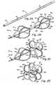
- FIGS. 2A-Dillustrates an exemplary occluder with which systems and techniques disclosed herein may be used.
- An occluder 70for example, can be formed by cutting a series of slits on tube 25.
- distal petals 32are produced by cutting slits 31 in the upper portion of tube 25 according to the cutting pattern shown in FIG. 2A .
- the distal portion of the tube 25is cut in half to form half sections 91a and 91b.
- the half sections 91a and 91bare further cut to a proximal distance from distal tip 39 into quarter sections 92a, 93a, 92b, and 93b.
- the cutsare discontinued and quarter sections 92a and 92b form half section 94a at distal tip 39, and quarter sections 93a and 93b form half section 94b at distal tip 39.
- struts defined by slits 31bow and twist outward to form distal petals 32 in distal side 30, as shown in FIGS. 2C-2D .
- the movement of the struts during deploymentis such that the struts rotate in an orthogonal plane relative to the axis of the device.
- Central tube 22may be constrained during the application of force F d , or any combination of forces sufficient to reduce the axial length of the tube 25 may be applied.
- each of distal petals 32originates from central tube 22, while the other end originates from distal tip 39 ( FIGS. 2B-2C ).
- Proximal petals 42may be formed in proximal side 40, as shown in FIGS. 2B-2D , making slits 41 between central tube 22 and proximal end 44, using the same cutting pattern described above.
- the tube(s) 25 forming occluder 70may be formed from a biocompatible metal or polymer.
- the occluder 70is formed of a bioabsorbable polymer, or a shape memory polymer. Shape memory polymers can be advantageous so that the structure of the device assists in pressing the PFO tunnel closed.
- the occluder 70is formed of a biocompatible metal, such as a shape memory alloy (e.g., nitinol).
- shape memory alloye.g., nitinol
- the occluder 70may be formed of a bioabsorbable metal, such as iron, magnesium, or combinations of these and similar materials.
- exemplary bioabsorbable polymersinclude polyhydroxyalkanoate compositions, for example poly-4-hydroxybutyrate (P4HB) compositions, disclosed in U.S. Patent No. 6,610,764 , entitled Polyhydroxyalkanoate Compositions Having Controlled Degradation Rate and U.S. Patent No. 6,548,569 , entitled Medical Devices and Applications of Polyhydroxyalkanoate Polymers.
- the cross-sectional shape of tube 25may be circular or polygonal, for example square, or hexagonal.
- the slits 31 and 41may be disposed on the face of the polygon (i.e., the flat part) or on the intersection of the faces.
- the tubecan be injection molded, extruded, or constructed of a sheet of material and rolled into a tube.
- the sheet of materialcould be a single ply sheet or multiple ply.
- the slits that form the strutscould be cut or stamped into the sheet prior to rolling the sheet into a tube to connect the ends to form an enclosed cross section.
- Various geometrical cross sectionsare possible including circular, square, hexagonal and octagonal and the joint could be at the vertex or along the flat of a wall if the cross section is of a particular geometery.
- Various attachment techniquescould be used to join the ends of the sheet to form a tube, including welding, heat adhesives, non-heat adhesives and other joining techniques suitable for in-vivo application.
- the petal configurationis the deployed configuration.
- the occluder 70can be secured in the petal configuration by a catch system that holds the ends of the tube 25 together, certain embodiments of which are described below.
- Use of the terms distal and proximal sides or portions 30 and 40, respectively,include the petals that are formed on the distal and proximal sides.
- FIGS. 2A-2Dhas similarities to the device disclosed in U.S. Patent Application No. 10/890,784 , entitled Tubular Patent Foramen Ovale (PFO) Closure Device with Locking Mechanism, filed on July 14, 2004; U.S. Patent Application No. 60/549,741 , entitled Delivery / Recovery System for Clover Leaf Septal Occluder, filed on March 3, 2004; U.S. Patent Application No. 60/612,857 , entitled Delivery / Recovery Systems for PFO Occluder with Catch System, filed September 24, 2004; U.S. Patent Application No. 60/663,289, filed March 18, 2005 , entitled Delivery / Recovery System for PFO Occluder with Catch System; U.S. Patent Application No.
- occluder 70enables occluder 70 to be delivered in a low profile, tubular form and to be converted readily, i.e., by reducing the axial length, in place to the high-profile deployed configuration. Moreover, the conversion can readily be effected by forcing distal end 39 and proximal end 44 together.
- distal side 30 and proximal side 40 of occluder 70may be deployed in separate steps, or both distal side 30 and proximal side 40 of occluder 70 may be exposed (e.g., out of the delivery catheter) prior to engaging the catch system and deployed together as the catch element is engaged.
- distal and proximal side 30 and 40include the loops or other geometries and configurations that are formed on the distal and proximal sides, respectively.
- Occluder 70may be prepared for delivery to an aperture 18 in any one of several ways.
- Slits 31 and 41may be cut such that tube 25 bends into its intended configuration following deployment in vivo.
- slits 31 and 41may be cut to produce struts 32 and 42 of a thickness that facilitates the bending and formation of loops 32 and 42 upon the application of forces F d and/or F p during deployment. See FIGS. 2B and 2C .
- a tube 25 formed of a shape memory materialmay be preformed into its intended configuration ex vivo so that it will recover its preformed shape once deployed in vivo. According to at least some embodiments, this preforming technique produces more reliable deployment and bending of occluder 70 in vivo.
- An intermediate approachmay also be used: tube 25 may be only slightly preformed ex vivo such that it is predisposed to bend into its intended shape in vivo upon application of forces F d and F p .
- FIG. 2Eshows a deployed occluder 70 in a human heart with a catch element 50 engaged.
- the term "catch system”describes the portion/aspect of the device that secures the device in the deployed configuration, it may be a single piece or a group of connected or assembled pieces.
- the catch elementis the portion of the catch system that engages with the occluder to hold the occluder in the deployed configuration and is described in more detail below.
- the configuration illustratedis a simplified schematic view of the occluder 70 illustrated in FIGS. 2A-2D . This particular type of occluder 70 and catch element 50 are described for purposes of illustration and explanation; of course, other types of occluders (with different types of catch elements or systems) can be deployed using the deployment systems described herein.
- the catch element 50is disposed in an axially central location in the occluder 70 and is schematically illustrated as a separate piece than the occluder 70.
- the catch elementmay be fixed to one end of the tube 25 that forms occluder 70.
- a flange 52may be fixed to the distal tip 39 of the tube 25 that forms the distal and proximal petals 32 and 42.
- references to "occluder 70" hereinmay be inclusive of catch element 50, depending on the context, for example, unless separately listed or otherwise stated.
- One end of tube 25is able to move with respect to the catch element 50 (and especially the catch system) so that the distal and proximal petals 32 and 42 can move from the delivery configuration to the deployed configuration.
- the inside surface of the tube 25is able to slide over the catch element 50 so that, when the proximal end 44 of the occluder 70 rests against the surface of the proximal flange 56, the occluder 70 is secured in its deployed configuration.
- the catch element 50is included in the catch system that includes a portion for connection to the delivery/recovery system, including, for example, a threaded section illustrated in FIG.
- the threaded sectionis an adaptation designed to fit with the desired type of securement system according to a preferred embodiment discussed herein and is not necessarily an inherent feature of the catch element 50.
- Occluder 70also includes an additional feature, such as threads or a groove 72 (as illustrated) to provide another connection between the occluder and the delivery/recovery system.
- FIG. 3Aillustrates the insertion of an occluder in a human subject 122 using a delivery assembly 124 in accordance with an aspect of the disclosure.
- a portion of delivery assembly 124including an occluder and a delivery mechanism for the occluder, which can be externally manipulated by a clinician, is inserted into the subject through an incision point 126.
- the distal end of the delivery assemblyis advanced toward and into the heart 10 until the distal end is in proximity to the defect to be closed, as seen in FIG. 3B .
- Figure 4Aillustrates the occluder 70 in the distal end of the delivery assembly 124, which includes a delivery system 140.
- a delivery systemgenerally includes a delivery catheter, a delivery wire and a delivery sheath. Because the occluder 70 is delivered percutaneously, the device is secured to the delivery system 140 so that the occluder 70 can be placed accurately at the desired delivery location. Securement systems are provided that attach the occluder to the delivery components. The securement systems are configured to provide accurate delivery of the occluder to the desired delivery location and allow for a controlled deployment so that the position of the device as it is being deployed can be monitored. Also, a device deployed according to this system is able to be retrieved and repositioned until the final stage of the deployment process. In some circumstances, after the final stage of the deployment process, the device can be retrieved. The manner in which the occluder is secured to the delivery system 140 and the process for deployment and/or retrieval of the occluder 70 are described in detail below.
- the delivery system 140includes a delivery sheath 144 and a delivery catheter 148.
- a delivery string or wire 150extends the length of the delivery assembly to the distal end of the occluder 70.
- the delivery system 140constrains the occluder 70 in its elongated delivery configuration.
- a delivery sheath 144 containing the occluder 70is first inserted into the right atrium 11 of the patient's heart.
- the delivery systemincluding the delivery sheath 144, may next be inserted through aperture 18 located in the septal tissue 12 (which, in this example, is a PFO tunnel) and into the left atrium 13.
- Distal side 30 of occluder 70is then exposed into the left atrium 13 by withdrawing the delivery sheath 144 then pulling force F 1 is applied to delivery string or wire 150 such that, for example, a catch element 50 passes through the central tube 22, thereby securing distal side 30 into its deployed state.
- Delivery sheath 144is withdrawn further through the aperture 18 and into the right atrium 11, such that central tube 22 is positioned through the aperture 18. As shown in FIG.
- proximal side 40 of occluder 70is then exposed into the right atrium 11, and a relative force between the proximal end 44 of the occluder 70 and the delivery string or wire 150 is applied such that a catch element 50 passes through the proximal end 44 of the occluder 70, thereby securing the proximal side 40 of the occluder into its deployed state.
- the occluder 70should remain in position during deployment of each side of the occluder 70 and pulling forces on the septum tissue should be avoided.
- occluder 70when properly deployed, occluder 70 is disposed through the aperture 18 with a portion of the device on the proximal side and another portion of the device on the distal side.
- the distal side 30 and proximal side 40exert a compressive force against septum primum 14 and septum secundum 16 in the left 13 and right 11 atria, respectively, to close the aperture 18, e.g. the PFO.
- the securement systemsare detached releasing the occluder from the delivery system. This delivery system is then removed from the heart.
- the occluder 70may be recovered by reversing the steps of the delivery sequence.
- the occluder 70is secured to the delivery system 140 at two locations on the occluder 70 so that the occluder 70 can be formed (i.e., compressed) into its deployed configuration.
- a first securementis toward the distal end of the occluder 70 whereby the occluder 70 is held by the delivery string or wire 150.
- the second securementis at the proximal end 44 of the occlude 70 whereby the occluder 70 is held by the delivery catheter 148.
- the first and second securementsallow the proximal and distal ends of the occluder 70 to be forced together so that the occluder 70 can move from the delivery configuration to the deployed configuration. They also allow the occluder 70 to be forced back into its low profile delivery configuration for redeployment or retrieval. Even if the occluder 70 were construced from shape memory material (e.g., Nitinol), the occluder 70 would preferably be secured to the delivery assembly 140 by first and second securements.
- shape memory materiale.g., Nitinol
- both securement systemsare able to move relative to one another during the delivery process and as a result, both securement systems cause the occluder 70 to move into the deployed configuration.
- the second securement systemis typically released and the first securement system is held while the position of the occluder 70 is evaluated by, for example, fluoroscopy, and if the position of the occluder 70 is appropriate, the first securement system is released.
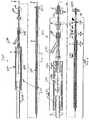
- FIG. 5shows delivery assembly 200, which includes a delivery system 220 with an occluder 224 to be delivered.
- the attached occluder 224is shown in a deployed configuration for convenience only. Prior to deployment, the occluder 224 would normally be in a low-profile configuration, contained within a delivery sheath 242.
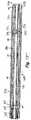
- FIG. 6shows delivery assembly 200 in an exploded cross-sectional side view. For convenience, the illustrations have been divided into two parts comprising a control portion 230 of the delivery system 220, and a catheter portion 250 of the delivery system 220 with the attached occluder 224, with the connection indicated by broken line LI.
- the control portion 230extends from a delivery wire control rod 232 to a delivery sheath control 240.
- the catheter portion 250extends from the delivery sheath control 240 to the end of the delivery system 220 where the occluder 224 is attached.
- the control portion 230remains external to the patient and incorporates the features provided for operation of the catheter portion 250 of the delivery system 220.
- FIG. 7shows an enlarged cross-sectional side view of the control portion 230.
- FIG. 8shows an enlarged cross-sectional side view of the catheter portion 250 and the occluder 224.
- the basic components of the delivery system 220are described below by reference to FIGS. 5-8 collectively.
- a delivery sheath 242encloses the components that are used to deliver occluder 224.
- a delivery catheter 244contains an inner delivery wire 246. Both of the delivery catheter 244 and delivery wire 246 connect to the occluder 224 during delivery. Although it may be considered advantageous to eliminate the central lumen in certain embodiments, in other embodiments the delivery wire 246 could also be tubular.
- the delivery wire 246should have sufficient tensile and compressive stiffness to withstand the steps required for the deployment and retrieval sequence. In this embodiment, the delivery wire 246 has a stiffer proximal portion and a more flexible distal portion.
- the delivery catheter 244also has a stiffer proximal portion and a more flexible distal portion.
- the combination of stiffness and flexibilityfacilitates delivery and positioning of the occluder 224.
- Both the delivery catheter 244 and the delivery wire 246may be made of two lengths of two different materials joined together in order to provide the requisite degree of stiffness in each portion of the element. Alternatively, the variation of stiffness can be the result of annealing, or some other material treatment process.
- the more flexible distal portionprevents undue distortion of the septal tissue during the delivery sequence.
- the delivery wireis further described infra.
- the control portion of the delivery system 230includes respective controls for the delivery sheath 242, the delivery catheter 244 and the delivery wire 246.
- the delivery wire 246can be advanced and retracted linearly, in the direction indicated by arrow D', and rotated with respect to the linear axis of the delivery system 220, in the direction indicated by arrow C'.
- the delivery wire control rod 232is a rod-like element that provides both linear and rotational control for the delivery wire 246.
- the delivery wire control rod 232slides linearly in the direction indicated by arrow C and rotates, with respect to the linear axis of the delivery system 220, in the direction indicated by arrow D to provide the corresponding motion in the delivery wire 246.
- the delivery catheter 244can be advanced and retracted linearly, in the direction indicated by arrow A', and rotated, with respect to the linear axis of the delivery system 220, in the direction indicated by arrow B'.
- a delivery catheter control 234is a tubular element that provides linear control for the delivery catheter 244, by sliding linearly in the direction indicated by arrow A.
- a delivery catheter rotational control 238provides rotational control of the delivery catheter 244, by rotating, with respect to the linear axis of the delivery system 220, in the direction indicated by arrow B.
- the delivery wire control rod 232connects to the delivery wire 246 inside the delivery catheter control 234.
- a perfusion port 236is provided to permit introduction of fluids into the delivery sheath 242.
- the delivery sheath 242can also be rotated, with respect to the linear axis of the delivery system 220, in the direction indicated by arrow F' and extended and retracted linearly along the direction indicated by arrow E'.
- a delivery sheath control 240provides linear and rotational control of the delivery sheath 242.
- the delivery sheath control 240can be rotated, with respect to the linear axis of the delivery system 220, in the direction indicated by arrow F and slided linearly in the direction indicated by arrow E to induce the corresponding motion in the delivery sheath 242.
- all three of the delivery sheath 242, delivery catheter 244 and delivery wire 246can be independently extended and retracted along and rotated around the longitudinal axis of the delivery system 220 relative to each other using the appropriate controls.
- the controlsare preferably designed to ergonomic specifications. Coordinated operation of the delivery sheath 242, delivery catheter 244 and delivery wire 246 allows for delivery (or retrieval) of the occluder 224.
- each element of the catheter portion 250can be manipulated individually and directly by the user of the delivery system 220, in alternate embodiments, the required operations could be partially or completely automated or synchronized.
- the delivery system 220Since the occluder 224 is delivered percutaneously, the delivery system 220 must be able to be secured so that the occluder 224 can be placed accurately at the desired delivery location and transformed into its deployed configuration.
- Securement systemsare provided that attach the delivery components to the occluder 224. The securement systems are typically released serially after proper placement of the occluder 224 is confirmed. The securement systems are configured to provide accurate delivery of the occluder 224 to the desired delivery location and allow for a controlled deployment. Also, a device deployed according to this mechanism is able to be retrieved and repositioned until the final stage of the deployment process. It is also possible to retrieve the device once it has been fully released.
- the delivery catheter 244 and delivery wire 246both contain features of securement systems on their distal ends for connecting to the occluder 224 and a catch system 180.
- the delivery wire 246terminates in a threaded portion 258 having a funnel-like profile.
- the threaded portion 258screws onto a mated threaded portion 182 provided on the proximal flange 184 of the catch element 188 for the occluder 224. These two threaded portions cooperatively form the first securement system.
- the delivery catheter 244terminates in a threaded portion 256 having a funnel-like profile.
- the threaded portion 256screws onto a mated threaded portion 226 provided on the frame of occluder 224.
- the first securement systemin effect secures the distal end of the occluder to the delivery system 220.
- the second securement systemsecures the proximal end 44 of the occluder 224 to the delivery system 220.
- the two-securement systemscooperatively allow the ends of the occluder 224 to be forced together or apart for deployment or retrieval.
- the funnel-like profileis useful for locating the corresponding threaded portion of the occluder 224 or the catch element 188 for attachment.
- the funnelprovides a channeling or guiding function.
- the funnelalso helps the delivery system 220 attach to the occluder 224 at extreme angles.
- the specific geometry of the funnel tipscan be modified to achieve better alignment with the device.
- disengages each securement systemby screwing together or unscrewing the respective elements from each other.
- distal and proximalgenerally refer to the disposition of the securement locations while the occluder 224 is in the delivery configuration in a delivery sheath, but the orientation of the securement systems may change during or after the delivery process.
- the threaded portions 256 and 258are both female threaded, while the corresponding threaded portion 182 of the proximal flange 184 and threaded portion 226 are male threaded.
- This configurationhas several advantages. First, a male thread in the occluder eliminates a cavity in the occluder 224 in which blood can stagnate and promote clotting. Second, the profile of the occluder 224 is reduced by using the male thread. Finally, the female connectors on the delivery system 220 can be provided with the funnel-like guides described above. In alternate embodiments, the male threads may be disposed on threaded portions 256 and 258. Also, threaded portions 256 and 258 need not have the same type of threads.
- Deployment of the occluder to a desired siteis typically a multi-step operation.
- the occluder 224is shown outside the delivery catheter for purposes of illustration.
- the delivery sheath 242contains occluder 224 in its elongated, delivery form, with the catch element 188 disengaged.
- the distal end of the delivery sheath 242 with the enclosed occluder 224is first inserted into the right atrium 11 of the patient's heart.
- the distal end of the delivery sheath 242 with the enclosed occluder 224may next be inserted through the anatomical aperture 18a located in the septal tissue 12, and into the left atrium 13.
- the distal side 30 of occluder 224is then deployed into the left atrium 13.
- the deployment processis described further below.
- the delivery sheath 242is withdrawn through the anatomical aperture 18a into the right atrium 11, such that central tube 22 of the occluder 224 is positioned through the anatomical aperture 18a.
- the proximal side 40 of the occluder 224is then deployed into the right atrium 11.
- the central tube 22When properly deployed, the central tube 22 is disposed at the anatomical aperture 18a, and the distal side 30 and proximal side 40 exert a compressive force against septum primum 14 in the left atrium 13 and septum secundum 16 in the right atrium 11, respectively, to close the anatomical aperture 18a, e.g. the PFO.
- the delivery system 220When the occluder 224 is properly deployed, the delivery system 220 is detached from the occluder 224, and the delivery sheath 242 with the delivery catheter 244 and delivery wire 246 are then withdrawn from the heart.
- the occluder 224may be recovered by reversing the steps of the delivery sequence. These sequences are described in more detail below.
- FIG. 9illustrates the initial step for a typical delivery sequence in accordance with one aspect of the disclosure, a high level view of which is shown in FIG. 3B .
- the occluder 224 and catch system 180are secured to the delivery wire 246 and to the delivery catheter 244, respectively.
- the female threaded portion 256 of the delivery catheter 244is screwed onto the male threaded portion 226 of the occluder 224.
- the female threaded portion 258 of the delivery wire 246is screwed onto the male threaded portion 182 of the catch element 188 of the occluder 224.
- the distal end of the delivery sheath 242 with the enclosed occluder 224is inserted through the aperture to be occluded, such as the anatomical aperture 18a of FIG. 1 , to approximately the midpoint of the occluder 224.
- the distal side 30 of the occluder 224is deployed on the distal side of the aperture in the left atrium 13.
- the distal portion 30is deployed by first retracting the delivery sheath 242 to expose the distal portion 30 of the occluder 224.
- the axial length of the occluder 224is then reduced by applying pulling force F 1 on delivery wire 246 with sufficient force to cause the catch element 188 to be pulled through the central tube 22 of the occluder 224 and the distal portion 30 of the occluder 224 to compress and distal petals 32 to form.
- Force F 2is simultaneously applied to the delivery catheter 244 to hold the occluder 224 stationary.
- the central tube 22 of the occluder 224catches on the catch element 188. This holds the distal petals 32 in place while the remainder of the deployment sequence is carried out.
- the proximal side 40 of the occluder 224is deployed on the proximal side of the aperture in the right atrium 11.
- the proximal portion 40is deployed by first retracting the delivery sheath 242 to expose the proximal portion 40 of the occluder 224.
- the proximal petals 42are then deployed by simultaneously advancing the delivery catheter 244 by applying force F 4 and retracting the delivery wire 246 by applying force F 5 to maintain the position of the occluder 224.
- the proximal end 44 of the occluder 224is pushed over the proximal end 44 of the catch element 188 and the occluder 224 is caught on the proximal flange 184 of the catch element 188.
- the final configurationis illustrated in FIG. 12 .
- the occluder 224can now be evaluated for proper deployment at the desired location.
- the occluder 224can be evaluated for proper deployment with the delivery system 220 attached or at least partially detached.
- the delivery system 220can be partially detached by releasing one of the securement systems provided by the delivery catheter 244 and the delivery wire 246.
- the delivery sheath 242can be further retracted and the delivery catheter 244 can be detached from the occluder 224.
- the delivery catheter 244can be detached by applying torque to unscrew the delivery catheter 244 from the proximal threaded portion 226 of the occluder 224 and retracting the delivery catheter 244.
- the delivery wire 246continues to secure the occluder 224, as illustrated in FIG. 14 .
- the more flexible distal portions of the delivery catheter 244 and the delivery wire 246allow the distal end of the delivery system 220 and the deployed occluder to be re-positioned so that the view is not obstructed.
- the positioning of the occluder 224can be evaluated using fluoroscopy or other appropriate techniques. If the delivery or deployment is not satisfactory, then the delivery system 220 can be used to retrieve the occluder 224.
- delivery catheter 244If delivery catheter 244 has been detached, it is reattached by advancing the threaded portion 256 of the delivery catheter 244 toward the threaded portion 226 of the occluder 224 and applying torque until the delivery catheter 244 is threaded onto the occluder 224. As mentioned before, the funnel-like shape of the threaded portion 256 of the delivery catheter 244 helps to guide the reattachment of this securement system. A similar technique is used to reattach the delivery wire 246 if needed.
- the delivery system 220can be detached in the sequence shown in FIGS. 13-15 .
- the delivery sheath 242is partially retracted by applying force F 12 .
- the delivery catheter 244is detached by applying torque F 14 to unscrew the threaded portion 256 of the delivery catheter 244 from the threaded portion 226 of the occluder 224.
- Force F 13is then applied to retract the delivery catheter 244 while simultaneously advancing the delivery wire 246 by applying force F 15 to maintain the position of the occluder 224.
- the occluder 224remains attached to the delivery system 220 by the second securement system provided by the delivery wire 246.
- the occluder 224can readily be returned to its low-profile configuration and removed at this point.
- the delivery catheter 244can be further retracted by applying force F 16 to provide an unobstructed view of occluder 224, again while the delivery wire 246 remains attached.
- the delivery wire 246can be detached by applying torque F17 to unscrew the threaded portion 258 of the delivery wire 246 from the threaded portion 182 of the catch element 188.
- the torque applied to remove the delivery wire 246 and the delivery catheter 244can be either clockwise or counterclockwise depending on the design of the device.
- the delivery wire 246can be retracted by applying force F 18 .
- the occluder 224is now fully deployed.
- the processinvolves reattaching the delivery catheter 244 and delivery wire 246 as mentioned above. Then force F 6 is applied to the delivery catheter 244 to pull the proximal portion 40 of the occluder 224 over the proximal end of the catch element 188. As the axial length of the occluder 224 is increased, the proximal petals 42 are unformed and the proximal portion 40 of the occluder 224 returns to its tubular profile. Referring to FIG.
- force F 8is applied to the delivery sheath 242 to advance the delivery sheath 242 over the proximal portion 40 of the occluder 224 and retain the proximal portion 40 of the occluder 224 in the low-profile configuration.
- force F 7is applied to delivery wire 246 in order to release the distal portion 30 of the occluder 224 and further increase the axial length of the occluder 224.
- FIG. 18the distal portion 30 of the occluder 224 is fully extended back into it low-profile configuration and forces F 9 and F 10 are applied to the delivery sheath 242 and the delivery catheter 244 in order to retrieve the occluder 224 back into delivery sheath 242. Referring to FIG.
- the delivery sheath 242 and enclosed occluder 224are removed from the anatomical aperture 18a and can further be fully removed from the heart 10 by applying force F11.
- This stepcan also be used as a starting point for redeployment of the occluder 224, i.e., the sequence shown beginning in FIG. 9 .
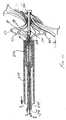
- FIG. 20illustrates an occluder 310 with a distal side 30 and a proximal side 40 that are connected by central tube 22.
- the configuration illustratedis a simplified schematic view of the occluder illustrated in FIGS. 2A-2D .
- the occluderincludes a catch system 320 that includes a distal flange 322, a catch body 324 and a catch element 326 in the shape of a cone.
- the catch system 320is disposed in an axially central location in the occluder 310.
- the catch system 320may be a single piece, or even fixed to one end of the tube that forms the proximal and distal loops by an adhesive, ultrasonic welding, or the like.
- the flange 322may be fixed to the end of the tube that forms the loops.
- the devicecan be formed from a single component or multiple components that are fixed together.
- the catch body 324is disposed axially within the inside surface of the tube that forms the loops. The tube is able to move with respect to the catch system (and the catch body) so that the petals can move from the delivery configuration to the deployed configuration.
- the inside surface of the tube 335is able to slide over the catch element 326 so that, when the proximal tip of the occluder 310 rests against the flat surface 326a of the catch element 326, the occluder 310 is secured in its deployed configuration.
- the first securement system 330includes a threaded component 332, illustrated as a male thread, and corresponding threads on a corresponding female portion described below in connection with FIGS. 22 and 23 .
- the second securement system 340includes a groove 314 on the proximal portion 40 of the occluder 310 that cooperates with a collet system 344 described below in connection with FIGS. 21 and 22 .
- the collet system 344also includes collet fingers 346 that are configured to have ends that fit within the groove 314 on the occluder 310.
- the collet systemalso includes a collet tube 348 onto which the collet fingers 346 are mounted and a collet sheath 350 that is movable with respect to the collet tube 348.
- the collet fingers 346are constructed of nitinol and have a splayed configuration when at rest as illustrated in FIG. 21 . More detail regarding the construction of the construction of the collet fingers 346 is provided below.
- collet fingers 346As the end of the collet sheath 350 is moved over the collet fingers 346, the collet fingers 346 are moved radially inward and when occluder 310 is being positioned in the delivery system, the collet fingers 346 are moved radially inward and engage the groove 314 on the occluder 310 (illustrated on the left side of FIG. 22 ).
- the collet sheath 350, collet tube 348 and collet fingers 346are described in more detail below.
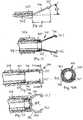
- FIG. 22illustrates a delivery system of a preferred embodiment
- the occluder 310is disposed within the delivery sheath 356.
- the first securement system 330 and the second securement system 340are each illustrated as securing the occluder 310 for delivery to the desired delivery location within the body.
- the securement systems 330 and 340are configured to provide accurate delivery of the occluder 310 to the desired delivery location and allow for a controlled deployment so that the position of the device as it is being deployed can be monitored.
- an occluder 310 deployed according to this systemis able to be retrieved and repositioned until the final stage of the deployment process. Even after the final stage of the deployment process, the occluder 310 can be retrieved.
- FIG. 22also illustrates the second securement system 340 in an engaged configuration.
- the collet fingers 346are disposed in the collet sheath 350 so that the collet fingers 346 engage groove 314 on the occluder 310.
- the occluder 310is secured by the collet fingers 346 against axial motion with respect to the collet sheath 350 and collet tube 348.
- the delivery wire 380is secured in an engaged configuration
- the occluder 310is secured against axial motion with respect to the delivery wire 380.
- the occluder 310is secured during delivery and the controlled motion of the collet sheath 350/collet tube 348 and the delivery wire 380 can deploy the occluder 310.
- FIG. 22the delivery wire 380 is threaded into the first securement system 330 by a threaded connection.
- the female threadscan be disposed on the delivery wire 380 and the male threads can be disposed on the occluder 310.
- FIG. 24illustrates an alternative embodiment of a first securement system, designated 390, in which the male threaded portion 392 is disposed on the delivery wire 380 and the female threaded portion 394 is disposed on the occluder 310.
- the male threadsare disposed on the occluder 310 and the female threads are disposed on the delivery wire 380.
- This configurationhas several advantages. First, the occluder 310 does not need a female connector and there is no cavity in which blood can stagnate and promote clotting. Second, the space required for the threaded connector 392 on the occluder 310 is diminished. Finally, a female connector on the delivery wire 380 may allow for a more smooth deployment of the occluder 310.
- the first securement systeminterconnects the delivery wire 380 to the threaded portion on the occluder 310.
- Representative embodiments of the first securement system and its componentsare illustrated in more detail in FIGS. 23 and 24 .
- the threaded portion 386interconnects the delivery wire 380 and the threaded portion 332 on the occluder 310, illustrated in FIG. 20 .
- the delivery wire 380has a more rigid section 382 and a more flexible section 384.
- the flexible section 384is distal to the more rigid section and is provided on the delivery end of the delivery wire 380.
- the delivery wire 380can be any kind of flexible elongate member such as a wire, tube, hypotube, coil, or other hollow or solid constructions.
- the delivery wire 380can be made from any material suitable for medical applications. Exemplary materials include metals and alloys suitable for medical applications, including stainless steel (such as "304 Stainless") and MP35N, polymers (such as nitinol), or any other suitable materials.
- the variation of stiffnesscan be the result of annealing; other material treatment process, or it may be a result of different materials being joined together.
- the amount of flexibility, or rigiditycan vary depending on the type of occluder being delivered and the delivery location within the body.
- the length of the flexible section 384would typically be about the length of the occluder 310 in its delivery configuration. That is, the occluder 310 in the delivery configuration would surround the flexible portion of the delivery wire 380.
- the length of the flexible section 384can be varied.
- the distal end of the delivery wire 380includes a threaded attachment portion 386 on the end of the flexible section 384, described in detail below.
- the threaded portion 386is illustrated as a female thread.
- FIGS. 25A, 25B , 26A, 26B, 27A, and 27Billustrate alternative embodiments of the first securement system 330.
- all of the securement embodiments describedcan be properly described as interlocking systems.
- Each of these embodiments of the first securement systemcan be used with the threaded or collet connection for the second securement system and provide alternatives which may be appropriate for different kinds of occluding devices or other devices that could be delivered by the delivery system described in this application
- FIGS. 25A and 25Billustrate a ball and claw type attachment.
- a ball 410is disposed on the occluder and two or more claws 412 are sized to secure the ball 410 within the claws 412.
- the claws 412are disposed at the distal end of the delivery wire 380.
- Two claws 412are illustrated in FIG. 25B .
- the claws 412operate under a similar principle as the collet design described previously. Specifically, there is a claw sheath 414 that is axially movable with respect to the claws 412. As illustrated in FIG. 25B the claws 412 splay out in the at rest configuration.
- the claws 412When the claws 412 are in the claw sheath 414, the claws 412 are sized to secure the ball 410. Thus the configuration allows for a secure placement of the occluder on the delivery system. When the occluder is ready to be released claw sheath 414 is withdrawn and the claws 412 splay out to the at rest confiduration. Thus the occluder is released from the first securement system.
- FIGS. 26A and 26Billustrate a pin-through-hole connector 420.
- fingers 422includes pins 424 that are disposed in an aperture in the occluder.
- the transverse aperture 428is formed in the occluder and the transverse aperture 428 is sized to receive the pins 424.
- the pins 424are secured within the transverse aperture 428.
- the configurationallows for a secure placement of the occluder on the delivery system.
- a sheath 426is withdrawn and the pins 424 spring back to the unbiased position similar to the fingers in the collet system.
- the occluderis released from the first securement system.
- a pair of cooperating configurationsare secured when disposed within a sheath and separable when the sheath is withdrawn.
- Thisis a type of interlocking system 440.
- the lockis achieved using a combination of two C-shaped elements.
- the occluderhas a portion 442 that extends in an axial direction and is adapted to mate with a delivery wire 444.
- the portion 442 and the delivery wire 444have cooperating extensions 446, 448 respectively that are able to interlock as illustrated in FIG. 27A .
- the system as illustratedhas an interlocking elbow/arm attachment 450, 452 on each of the protrusion and the delivery wire.
- interlocking configurationsare possible and the concept should not be limited to the configuration illustrated.
- the interlocking systemWhen the interlocking system is disposed within a sheath 454, the cooperating extension cannot move with respect to each other.
- the configurationallows for a secure placement of the occluder on the delivery system.
- the cooperating extensionsWhen the cooperating extensions are extended beyond the sheath 454, the interlocking system can release and the occluder is released from the first securement system.
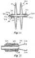
- FIG. 28illustrates the occluder 310 in its deployed configuration.
- the delivery sheath 356is withdrawn to expose the distal side loops 30 and then the proximal side loops 40 into the defect to be occluded.
- the catch element 326is engaged so that the occluder 310 is secured in the deployed configuration.
- the collet sheath 350is withdrawn and the collet fingers 346 are unconstrained by the collet sheath 350 and are allowed to move radially outward to the unbiased condition, as illustrated in FIG.
- the occluder 310is only attached to the delivery by the first securement system 330. In this position, the clinician is able to evaluate the position of the occluder 310 to make sure that the device is properly positioned.
- the process of retrieving an occludervaries based on the state of the delivery when the decision to retrieve the occluder is made. If the second and first securement systems are still attached and the catch system has not secured the device in the deployed configuration, then the retrieval process is simply a reversal of the deployment process. The second securement system is pulled and the device can be withdrawn into delivery sheath 356 and removed from the body.
- the processis the same with the addition of moving the catch element of the occluder relative to the second securement so that the device can be elongated. Once that occurs, the device can be withdrawn as described above.
- the retrieval process for an occluder in which the second securement system is a collet system, which has been disengagedrequires an additional step.
- the collet systemis advanced until the collet fingers are in alignment with the groove on the occluder.
- the collet sheathis advanced over the collet fingers such that the fingertips fit within the groove on the occluder.
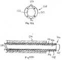
- FIG. 30illustrates a detail view of a collet finger 346 and the collet sheath 350.
- the collet finger 346is configured to be about 20 degrees from the base of the collet finger 346, the dimension identified as ⁇ in FIG. 30 .
- the collet finger 346can extend from the collet tube 348 approximately 0.25 in., the dimension identified as "a" in FIG. 30 .
- the distance "a”can be from 0.1 in. to 0.5 in.
- the angle ⁇can vary from low single digits to approximately 70 degrees. In general, as the length of "a" is decreased, the angle desired for ⁇ would increase.
- the collet finger 346includes a radially inwardly extending protrusion 347, which is formed by a bend in the nitinol finger.
- the bendis preferably 90 degrees and the dimensions of the protrusion are selected to securely fit within the groove 314.
- the groove 314for example, could be 0.02 - 0.04 in. in axial length and 0.005-0.020 in radial depth.
- the groove 314is illustrated as a circumferential groove; alternatively, recesses can be formed in part of the occluder 310 to receive the collet fingers 346. It is preferable that the collet fingers 346 have a close fit but not an interference fit in the axial direction. This assures that the collet system can move the device without significant slippage. It is also preferable that the protrusion does not come into contact with the bottom of the groove 314 (the innermost radial surface). This assists the deployment of the occluder.
- FIGS. 31, 32A, and 32Billustrate alternative embodiments of the second securement system.
- the fingersare formed by cutting sections from a nitinol hypotube that has, for example, a .0075 in. wall thickness.
- the inner diametercould be, for example, 0.098 in. and the outer diameter could be 0.117 in.
- the thickness of the hypotubecould be as large as 0.050 in.or more.
- Nitinolis a desirable material due to its superelastic characteristics. Other superelastic materials or simply springy material may be used. Of course, the materials would have to be suitable for use in a medical device.
- the nitinol hypotubeis cut so that the fingers extend from one side and the hypotube ring is uncut at the other end. As an example, FIG.
- the 31illustrates a cross section where the hypotube is disposed on an end of the collet tube 348.
- the nitinol ring 355is disposed on the outside surface of the collet tube.
- the nitinol ring 355may be affixed to the collet tube 348 by a variety of known techniques such as a suitable adhesive.
- FIGS. 32A and 32Billustrate the side and end view of representative collet fingers 346.
- One practical limitationis the circumferential size of the collet fingers 346 and the rigidity of the collet fingers 346 as they are used to deploy the occluder.
- the four collet fingers 346are formed by cutting away a 1/8 th section of the cross section and forming four equally spaced collect fingers 346. During the formation process the roundness of the collet finger 346 along the circumference can be modified to adjust the bendability of the collet fingers 346.
- FIG. 33illustrates another embodiment of the collet fingers 346.
- the collet fingers 346include a bend 358 between the base ring 355 and the protrusion 347. As illustrated the bend 358 is in the approximate halfway between the base ring 355 and the protrusion 347.
- the bend 358can be almost any configuration but the bend 358, as illustrated, allows for force to be applied to the occluder and have the configuration of the collet fingers 346 be such that it does not extend the so far away from the collet tube 348 in the radial direction. This allows the occluder to have a more controlled delivery because of the increased forces applied and a more compact system because the collet fingers 346 do not extend radially away from the collet tube 348 as far.
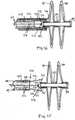
- FIGS. 34-37Another embodiment of the second and first securement system of the delivery system, illustrated in FIGS. 34-37 , uses a filament instead of a delivery wire.
- the second securement system 340is illustrated as the collet system 344, which is largely the same as in the previous embodiment.
- other securement systems included a threaded connectioncan be used.
- the first securement systemincludes an eyelet 510 around which a flexible filament 512 can be fastened or looped.
- the flexible filamentcan be a suture thread (monofilament or polyfilament), a thin metallic wire or other flexible material that can withstand a tension load.
- the deployment of the occluderis effected by withdrawing the delivery sheath 356 to expose and let the distal petals 30 on the distal side of the occluder expand as illustrated in FIG. 35 .
- the delivery sheath 356is repositioned to the deployment site of the proximal petals 40 and the proximal petals 40 are exposed as illustrated in FIG. 36 .
- the filamentis pulled to cause the catch element at the proximal side of the occluder to be secured.
- the collet systemis released in the manner described above and illustrated in FIG. 37 . Once the collet system is released, the position may be evaluated.
- filament 510is pulled through the eyelet and removed from the body.
- Either a delivery wire, a tube or filamentis appropriate for the second securement system depending on the design considerations. For example, if the occluder in the delivery configuration lacks sufficient column strength to have the delivery sheath pull back without affecting the position of the device in the delivery system, a delivery wire that has some column strength would be more desirable.
- filaments 514are attached to the proximal end 44 of the occluder 570 through holes 516.
- the filaments 514can be attached in a variety of locations, for example, they can be looped around one of the proximal loops on the proximal side of the device.
- the filaments 514can be cut or otherwise withdrawn from the body.
- FIG. 38Aillustrates an end view of the construction of the delivery catheter 548.
- the delivery catheter 548a central lumen 556 and secondary lumens 554 surrounding the central lumen 556.
- the outer lumens 554are used to provide a passageway for containing sutures 558 secured to the occluder 570, illustrated in FIG. 38C , as the attachment mechanism for the second securement system 340 and passed through the delivery catheter 548 to the user for manipulating the second securement system.
- four outer lumens 554are shown, any number of lumens may be provided suitable for use in the delivery system 340.
- a sufficient number of sutures 558should be provided in order to securely attach the occluder 570 and permit the necessary operations.
- the sutures 558are shown in FIG.
- FIG. 38Bwhich illustrates sheath delivery 544 which contains delivery catheter 548.
- the delivery catheter 548is connected to the proximal end 44 of the occluder 570 via the sutures 558 which attach to holes 560 provided in the occluder 570.
- the sutures 558are threaded through the holes 560 and can be readily detached by, e.g., cutting the sutures and pulling through the delivery catheter 548.
- Attachment of the sutures 558 to the occluder 570may be provided in a number of ways, such as providing hooks or a flange on the occluder 570, around which the sutures can be wrapped or fastened, or wrapping the sutures 558 around the proximal petals 42.
- the sutures 558can also be embedded into the proximal end 44 of the occluder 570.
- the flexible filament used to provide the threadcan be a suture thread (monofilament or polyfilament), a thin metallic wire or other flexible material that can withstand a tension load.
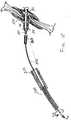
- FIG. 39illustrates a complete delivery assembly 700 with the occluder 570 in place for delivery and deployment at the deployment site.
- the occluder 570is in its elongated, low profile configuration.
- the occluder 570is secured at its distal end 39 by the first securement system 330 to the delivery wire 380 and at its proximal end 44 by the second securement system 550 to the delivery catheter 548.
- the occluder 570, delivery wire 380 and delivery catheter 548are contained within the sheath 544.
- the occluder 570can be detached from the first securement system 330 by unscrewing the delivery wire 330, which is connected by threaded portion 386 to threaded portion 332.
- the occluder 570can be detached from the second securement system 550 by removing the sutures 558, for example, by pulling on them from the user end of the delivery system.
- the embodiments and techniques described hereare described preferably for use with a device made of a polymer and formed from a single tube, such that the tube is a single monolithic material.
- the catch mechanismcan be all or partly monolithic or integral with the tubular structure, or there can be an absence of any type of bonding or rigid connection to the rest of the tubular structure, in which case there may be some spring force or other force that holds the locking mechanism in place. While the device is thus shown as being substantially formed from a single tubular body, the catch mechanism as described in the embodiments above could be used with other types of devices, including those formed from many pieces, and including devices formed from other materials, including metals, polymers, stainless steel or nitinol.
- bioabsorbableas used in the description above, is also understood to mean “bioresorbable.”
- wiremight convey a more rigid piece than a string, a suture or a filament
- all these termsare essentially interchangeable, and further include embodiments in which the wire, string, suture or filament is a hollow tube or conduit to allow another wire, as needed, to pass through its longitudinal axis.
- Each wire, string, suture and filamentcan be composed of one or more wires, strings, sutures and filaments.
- the deviceis made of a polymer
- the sequencemay be varied in certain respects, or the steps may be combined, while still obtaining the desired deployment or in some cases to effect deployment in a particular way.
- the delivery sheathmay be advanced or retracted at varying times and in varying degrees, the proximal and distal portions of the occluder may be deployed into the petal configuration in a different sequence, etc.
- the stepscould be automated.
Landscapes
- Health & Medical Sciences (AREA)
- Surgery (AREA)
- Life Sciences & Earth Sciences (AREA)
- Biomedical Technology (AREA)
- Nuclear Medicine, Radiotherapy & Molecular Imaging (AREA)
- Engineering & Computer Science (AREA)
- Cardiology (AREA)
- Heart & Thoracic Surgery (AREA)
- Medical Informatics (AREA)
- Molecular Biology (AREA)
- Animal Behavior & Ethology (AREA)
- General Health & Medical Sciences (AREA)
- Public Health (AREA)
- Veterinary Medicine (AREA)
- Surgical Instruments (AREA)
Description
- This invention relates generally to occlusion devices for the closure of physical anomalies, such as an atrial septal defect, a patent foramen ovale, and other septal and vascular defects. The invention also relates to delivery systems and mechanisms for such devices.
- A patent foramen ovale (PFO), illustrated in
FIG. 1 , is a persistent, one-way, usually flap-like opening in the wall between theright atrium 11 andleft atrium 13 of theheart 10. Because left atrial (LA) pressure is normally higher than right atrial (RA) pressure, the flap usually stays closed. Under certain conditions, however, right atrial pressure can exceed left atrial pressure, creating the possibility that blood could pass from theright atrium 11 to theleft atrium 13 and blood clots could enter the systemic circulation. It is desirable that this circumstance be eliminated. - The foramen ovale serves a desired purpose when a fetus is gestating. Because blood is oxygenated through the umbilical cord, and not through the developing lungs, the circulatory system of the fetal heart allows the blood to flow through the foramen ovale as a physiologic conduit for right-to-left shunting. After birth, with the establishment of pulmonary circulation, the increased left atrial blood flow and pressure results in functional closure of the foramen ovale. This functional closure is subsequently followed by anatomical closure of the two over-lapping layers of tissue:
septum primum 14 and septum secundum 16. However, a PFO has been shown to persist in a number of adults. - The presence of a PFO is generally considered to have no therapeutic consequence in otherwise healthy adults. Paradoxical embolism via a PFO is considered in the diagnosis for patients who have suffered a stroke or transient ischemic attack (TIA) in the presence of a PFO and without another identified cause of ischemic stroke. While there is currently no definitive proof of a cause-effect relationship, many studies have confirmed a strong association between the presence of a PFO and the risk for paradoxical embolism or stroke. In addition, there is significant evidence that patients with a PFO who have had a cerebral vascular event are at increased risk for future, recurrent cerebrovascular events.
- Accordingly, patients at such an increased risk are considered for prophylactic medical therapy to reduce the risk of a recurrent embolic event. These patients are commonly treated with oral anticoagulants, which potentially have adverse side effects, such as hemorrhaging, hematoma, and interactions with a variety of other drugs. The use of these drugs can alter a person's recovery and necessitate adjustments in a person's daily living pattern.
- In certain cases, such as when anticoagulation is contraindicated, surgery may be necessary or desirable to close a PFO. The surgery would typically include suturing a PFO closed by attaching septum secundum to septum primum. This sutured attachment can be accomplished using either an interrupted or a continuous stitch and is a common way a surgeon shuts a PFO under direct visualization.
- Umbrella devices and a variety of other similar mechanical closure devices, developed initially for percutaneous closure of atrial septal defects (ASDs), have been used in some instances to close PFOs. These devices potentially allow patients to avoid the side effects often associated with anticoagulation therapies and the risks of invasive surgery. However, umbrella devices and the like that are designed for ASDs are not optimally suited for use as PFO closure devices.
- Currently available septal closure devices present drawbacks, including technically complex implantation procedures. Additionally, there are significant complications due to thrombus, fractures of the components, conduction system disturbances, perforations of heart tissue, and residual leaks. Many devices have high septal profile and include large masses of foreign material, which may lead to unfavorable body adaptation of a device. Given that ASD devices are designed to occlude holes, many lack anatomic conformability to the flap-like anatomy of PFOs. Thus, when inserting an ASD device to close a PFO, the narrow opening and the thin flap may form impediments to proper deployment. Even if an occlusive seal is formed, the device may be deployed in the heart on an angle, leaving some components insecurely seated against the septum and, thereby, risking thrombus formation due to hemodynamic disturbances. Finally, some septal closure devices are complex to manufacture, which may result in inconsistent product performance.
WO 2005/006990 discloses a device for occluding an anatomical aperture comprising a tube which is cut to form struts, which struts deform into loops upon the application of force. Also disclosed is a catch system that maintains the deployed state of the occluderin vivo, the catch system comprising two members e.g. balls attached to a delivery string which bring together the distal side and the proximal side of the occluder.WO 2005/110240 discloses a septal occluder comprising an expanded configuration and a reduced configuration and a catch system for securing the septal occluder in the expanded configuration.- Various delivery systems have been used to deliver occluders and other medical devices through body lumens. Some delivery systems of the prior art are used to deliver devices that readily expand to a delivered configuration when removed from the delivery system. Such delivery systems are not generally suited for delivering a device that does not readily expand into the delivered configuration. Further, the delivery systems of the prior art may not allow verification of the position of the device prior to full deployment of the device. Finally delivery systems of the prior art may not be suitable to manipulate the configuration of the device in a secure manner to allow for complete deployment of the device.
- The devices and techniques disclosed herein are designed to address these and other deficiencies of prior art septal closure devices and techniques for delivering and retrieving such devices.
- These and other aspects and embodiments of the disclosure are illustrated and described below. Aspects of the present invention are set out in the independent claims. Preferred embodiments of these aspects are set out in the dependent claims.
- This description discloses several delivery devices and techniques for delivering an implant into a desired location within the body. This delivery technique relates particularly to, but is not limited to, a septal occluder made from a polymer tube. These delivery techniques, in addition to use with septal occluders, could be applied to other medical devices, such as other expandable devices constructed from an underlying tubular structure.
- In one aspect, a delivery system is disclosed for delivering an occluder that closes an aperture in septal tissue. The occluder includes a first side adapted to be disposed on one side of the septal tissue and a second side adapted to be disposed on the opposite side of the septal tissue. The first and second sides are adapted to occlude the aperture upon deployment of the device at its intended delivery location. The device also includes a catch system that maintains the configuration of the device once it has been deployed.
- According to at least some embodiments, the device is formed from a tube. According to some embodiments, the tube includes a material selected from the group consisting of metals, shape memory materials, alloys, polymers, bioabsorbable polymers, and combinations thereof. In particular embodiments, the tube includes a shape memory polymer. In particular embodiments, the tube includes nitinol. In some embodiments, the tube is formed by rolling a flat piece of material into a tubular form. According to some embodiments, the device is formed by cutting the tube. The device is placed in its deployment configuration by reducing the axial length of the device.
- According to some embodiments, the catch system reduces and maintains the axial length of the device. Also, varied constructions could be used to maintain the axial dimension of the device. In one form, catch elements such as, for example, balls, attached to a delivery wire could be used to maintain the axial dimension of the device. In a different construction, a locking mechanism could be used. Preferably, if a locking mechanism is used, it secures both sides of the device in the locked position with a single locking element. In some embodiments, a catch element secures the ends of the occluder in a compressed position. Preferably, if a catch mechanism is used, it secures both sides of the device in the deployed position with a single element.
- In another aspect, a device for occluding an aperture in septal tissue is disclosed, including a first side adapted to be disposed on one side of the septal tissue and a second side adapted to be disposed on the opposite side of the septal tissue. The first and second sides are adapted to occlude the defect when the device is deployed at its intended delivery location. Each of the first and second sides includes loops. The device further includes a catch system that maintains the configuration of the device once it has been deployed. The loops of the first and second sides and the catch system cooperate to provide a compressive force to the septal tissue surrounding the aperture.
- According to some embodiments, each of the first and second sides includes at least two loops. In particular embodiments, each of the first and second sides includes four or six loops. Of course, the most desirable number of loops on each side will depend on a variety of anatomical and manufacturing factors. According to some embodiments, the device also includes a central tube that connects the first and second sides.
- The delivery system may be used to deliver an occluder in which at least one of the first and second sides further includes a tissue scaffold. The tissue scaffold includes a material selected from the group consisting of polyester fabrics, Teflon-based materials, polyurethanes, metals, polyvinyl alcohol (PVA), extracellular matrix (ECM) or other bioengineered materials, synthetic bioabsorbable polymeric scaffolds, collagen, and combinations thereof. In particular embodiments, the tissue scaffold includes nitinol.
- The delivery system includes a first and a second securement system. The first securement system may be any one of a number of configurations. First, a delivery wire may be used to secure the distal end of the occluder onto the delivery system. When a delivery wire is used, the distal end of the delivery wire may be threaded and cooperate with a corresponding threaded portion on the occluder. In a preferred form, the threaded portion may have male threads on the occluder and female threads on the delivery wire. Alternatively, a ball and clasp, other interlocking system may be used.
- The second securement system may be any one of a number of configurations. In one aspect it may be a threaded connection between the delivery system and the occluder. In another aspect, the second securement system is a collet system that includes fingers, which are configured to fit within a groove in the occluder and thus secure the occluder to the delivery system when the fingers are disposed in the groove. A collet sheath is moveable with respect to the fingers and when the collet fingers are disposed within the collet sheath, the fingers are configured to fit within the groove provided on the occluder.
- In one aspect, a delivery system for the device is provided within (and includes) a delivery sheath. In certain embodiments, the delivery system includes a first securement system for securing a first end of the occluder and a second securement system for securing a second end of the occluder. The securement systems connect the occluder to first and second catheters contained in the delivery system and enable deployment and/or retrieval of the occluder. The catheters are preferably able to move relative to each other. The securement systems enable pushing and pulling of respective ends of the occluder by manipulating the catheters to expand and contract the device. The first securement system may employ a threaded connection and the second securement system may employ a suture connection. The securement systems are detached when the device has been properly positioned.
- In a further aspect, the first securement system secures a distal end of a catching system of the device and the second securement system secures a proximal end of the device. A first catheter connects to the first securement system and a second catheter connects to the second securement system. In certain embodiments, the second catheter encloses the first catheter in its central lumen. In one aspect, the device is deployed by inserting the delivery system, removing the sheath, expanding the petals of a distal portion of the device, and expanding the petals of a proximal portion of the device. The delivery system can be detached by detaching the first and second securement systems, e.g., by unscrewing the first securement system and by cutting and removing the sutures. In another aspect, the deployed device is retrieved by contracting the petals of a proximal portion of the device using the second catheter, advancing the sheath over a proximal portion of the device, contracting the petals of a distal portion of the device using the first catheter and advancing the sheath over the distal portion of the device. The occluder can then be repositioned or removed.
- In another aspect, a delivery system is disclosed for delivering an occluder that closes an aperture in septal tissue. The occluder includes a first side adapted to be disposed on one side of the septal tissue and a second side adapted to be disposed on the opposite side of the septal tissue. The first and second sides are adapted to occlude the aperture upon deployment of the device at its intended delivery location. The device also employs a catch system that maintains the configuration of the device once it has been deployed. The occluder may be held in its deployment configuration by the catch element.
- In one aspect, a delivery system for the device is provided within a delivery sheath. In certain embodiments, the delivery system includes a first securement system for securing a first end of the occluder and a second securement system for securing a second end of the occluder. The securement systems connect the occluder to first and second extrusions, e.g., a catheter or a wire, contained in the delivery system and enable deployment and/or recovery of the occluder. The extrusions are preferably able to move relative to each other. The securement systems enable pushing and pulling of respective ends of the occluder by manipulating the extrusions to expand and contract the device by varying its axial length. The first securement system may employ a threaded connection. The second securement system may also employ a threaded connection. The securement systems are detached when the device has been properly positioned. The securement systems can be manipulated by control systems provided in the control portion of the delivery system.
- In one preferred embodiment, an axially collapsible occluder, a means for collapsing and expanding the occluder by changing the distance between the distal and proximal ends of the occluder, and a means for keeping the axial distance between the proximal and distal ends of the occluder fixed after its deployment are provided.
- These and other aspects and embodiments of the disclosure are illustrated and described below
- In the Drawings:
FIG. 1 is a schematic representation of a human heart including various septal defects;FIGS. 2A-2D are isometric views of an embodiment of an occluder for use with disclosed delivery systems and techniques;FIG. 2E illustrates a deployed occluder according to an aspect of the disclosure;FIG. 3A illustrates insertion of an occluder in a human subject using a delivery system in accordance with an aspect of the disclosure;FIG. 3B illustrates introduction of the occluder in a human heart using a delivery system in accordance with an aspect of the disclosure;FIGS. 4A-4D are side views of a delivery assembly for delivering an occluder to a septal defect according to an aspect of the disclosure;FIG. 5 is a side elevational view of a delivery system attached to an occluder in deployed configuration according to an aspect of the disclosure;FIG. 6 is an exploded cross-sectional side view of a delivery system attached to an occluder in deployed configuration according to an aspect of the disclosure;FIG. 7 is an exploded cross-sectional side view of the control portion of a delivery system according to an aspect of the disclosure;FIG. 8 is an enlarged cross-sectional side view of the catheter portion of a delivery system attached to an occluder according to an aspect of the disclosure;FIG. 9 is a cross-sectional side view of the catheter portion of the delivery system attached to a collapsed occluder according to an aspect of the disclosure;FIG. 10 is a cross-sectional side view of one step in a deployment sequence according to an aspect of the disclosure;FIG. 11 is a cross-sectional side view of one step in a deployment sequence according to an aspect of the disclosure;FIG. 12 is a cross-sectional side view of one step in a deployment sequence according to an aspect of the disclosure;FIG. 13 is a cross-sectional side view of one step in a detachment sequence according to an aspect of the disclosure;FIG. 14 is a cross-sectional side view of one step in a detachment sequence according to an aspect of the disclosure;FIG. 15 is a cross-sectional side view of one step in a detachment sequence according to an aspect of the disclosure;FIG. 16 is a cross-sectional side view of one step in a retrieval sequence according to an aspect of the disclosure;FIG. 17 is a cross-sectional side view of one step in a retrieval sequence according to an aspect of the disclosure;FIG. 18 is a cross-sectional side view of one step in a retrieval sequence according to an aspect of the disclosure; andFIG. 19 is a cross-sectional side view of one step in a retrieval sequence according to an aspect of the disclosure.FIG. 20 illustrates a cross-sectional schematic of a deployed occluder according to an aspect of the disclosure;FIG. 21 illustrates a cross-sectional side view of several components of the delivery system according to one embodiment of disclosure;FIG. 22 is an axial cross-sectional drawing of an occluder, in a delivery configuration, according to an embodiment of the disclosure;FIG. 23 is a detail view of the delivery wire according to an aspect of one embodiment of the disclosure;FIG. 24 is a configuration for a first securement system according to an embodiment of the disclosure;FIGS. 25A, 25B ,26A, 26B, 27A and 27B are alternative configurations for the first securement system according to aspects of the disclosure;FIGS. 28 and 29 are detail cross-sectional side view of the delivery system during two steps in the deployment process according to one aspect of the disclosure;FIG. 30 is a detail view of the collet finger according to one aspect of the disclosure;FIG. 31 is a detail cross-sectional side view of the collet system in the splayed configuration;FIG. 32A is a detail cross-sectional view of the collet system in the constrained configuration;FIG. 32B is a cross-section taken alonglines 32B-32B inFIG. 32A ;FIG. 33 is a detail sectional view of another embodiment of the collet system according to the disclosure;FIGS. 34-37 are sectional views of an alternative delivery system according to an aspect of the disclosure;FIG. 38A is a front cross-sectional view of a delivery catheter according to one embodiment of the disclosure;FIG. 38B is a side cross-sectional view of a delivery catheter with sutures according to one embodiment of the disclosure;FIG. 38C is an elevational view of a delivery catheter with sutures secured to an occluder according to one embodiment of the disclosure;FIG. 38D is an elevational end view of delivery catheter alonglines 38D ofFIG. 38C ; andFIG. 39 is a sectional view of a delivery assembly during a step in the deployment process according to one aspect of the disclosure.- The present disclosure provides devices, delivery/retrieval systems and techniques for delivering such devices intended to occlude an aperture within body tissue. In particular and as described in detail below, the described occluder may be used for closing an ASD or PFO in the atrial septum of a heart. Although the embodiments are described with reference to an ASD or PFO, one skilled in the art will recognize that the device and methods disclosed may be used to treat other anatomical conditions. As such, the disclosure should not be considered limited in applicability to any particular anatomical condition. In addition, the systems and methods for delivery and retrieval, and for catching a device in a deployed state, which are aspects of the present disclosure may also be used in connection with other types of devices besides an occluder, in particular, devices having tubular profiles.
FIG. 1 illustrates ahuman heart 10, having aright atrium 1 1 and aleft atrium 13 and including variousanatomical apertures 18a and 18b. Theatrial septum 12 includes septum primum 14 andseptum secundum 16. The anatomy of theseptum 12 varies widely within the population. In some people, septum primum 14 extends to and overlaps withseptum secundum 16. The septum primum 14 may be quite thin. When the anatomical apertures 18a is present, blood could travel through the anatomical aperture 18a between septum primum 14 and septum secundum 16 (referred to as "the PFO tunnel"). Additionally or alternatively, the presence of an ASD could permit blood to travel through an aperture in the septal tissue, such as through theanatomical aperture 18b.- In this application, "distal" refers to the direction away from a catheter insertion location and "proximal" refers to the direction nearer the insertion location. Additionally, the term "delivery configuration" refers to the configuration of a device, such as an occluder, when it has a reduced profile in a delivery catheter. The term "deployed configuration" refers to the configuration of the device, such as an occluder, when it has deployed from the catheter, such as at the desired implantation location.
FIGS. 2A-D illustrates an exemplary occluder with which systems and techniques disclosed herein may be used. Anoccluder 70, for example, can be formed by cutting a series of slits ontube 25. As shown inFIGS. 2A-2D ,distal petals 32 are produced by cuttingslits 31 in the upper portion oftube 25 according to the cutting pattern shown inFIG. 2A . As shown inFIG. 2B , the distal portion of thetube 25 is cut in half to formhalf sections half sections distal tip 39 intoquarter sections quarter sections distal tip 39, andquarter sections 93a and 93b form half section 94b atdistal tip 39. Upon application of force Fd todistal tip 39, struts defined byslits 31 bow and twist outward to formdistal petals 32 indistal side 30, as shown inFIGS. 2C-2D . The movement of the struts during deployment is such that the struts rotate in an orthogonal plane relative to the axis of the device.Central tube 22 may be constrained during the application of force Fd, or any combination of forces sufficient to reduce the axial length of thetube 25 may be applied. One end of each ofdistal petals 32 originates fromcentral tube 22, while the other end originates from distal tip 39 (FIGS. 2B-2C ).Proximal petals 42 may be formed inproximal side 40, as shown inFIGS. 2B-2D , making slits 41 betweencentral tube 22 andproximal end 44, using the same cutting pattern described above.- The tube(s) 25 forming
occluder 70 may be formed from a biocompatible metal or polymer. In at least some embodiments, theoccluder 70 is formed of a bioabsorbable polymer, or a shape memory polymer. Shape memory polymers can be advantageous so that the structure of the device assists in pressing the PFO tunnel closed. In other embodiments, theoccluder 70 is formed of a biocompatible metal, such as a shape memory alloy (e.g., nitinol). The thermal shape memory and/or superelastic properties of shape memory polymers and alloys permit theoccluder 70 to resume and maintain its intended shape in vivo despite being distorted during the delivery process. Alternatively, or additionally, theoccluder 70 may be formed of a bioabsorbable metal, such as iron, magnesium, or combinations of these and similar materials. Exemplary bioabsorbable polymers include polyhydroxyalkanoate compositions, for example poly-4-hydroxybutyrate (P4HB) compositions, disclosed inU.S. Patent No. 6,610,764 , entitledPolyhydroxyalkanoate Compositions Having Controlled Degradation Rate andU.S. Patent No. 6,548,569 , entitledMedical Devices and Applications of Polyhydroxyalkanoate Polymers. - The cross-sectional shape of
tube 25 may be circular or polygonal, for example square, or hexagonal. Theslits 31 and 41 may be disposed on the face of the polygon (i.e., the flat part) or on the intersection of the faces. - The tube can be injection molded, extruded, or constructed of a sheet of material and rolled into a tube. The sheet of material could be a single ply sheet or multiple ply. The slits that form the struts could be cut or stamped into the sheet prior to rolling the sheet into a tube to connect the ends to form an enclosed cross section. Various geometrical cross sections are possible including circular, square, hexagonal and octagonal and the joint could be at the vertex or along the flat of a wall if the cross section is of a particular geometery. Various attachment techniques could be used to join the ends of the sheet to form a tube, including welding, heat adhesives, non-heat adhesives and other joining techniques suitable for in-vivo application.
- The petal configuration is the deployed configuration. The
occluder 70 can be secured in the petal configuration by a catch system that holds the ends of thetube 25 together, certain embodiments of which are described below. Use of the terms distal and proximal sides orportions - The embodiment described in conjunction with
FIGS. 2A-2D has similarities to the device disclosed inU.S. Patent Application No. 10/890,784 U.S. Patent Application No. 60/549,741 U.S. Patent Application No. 60/612,857 U.S. Patent Application No. 60/663,289, filed March 18, 2005 U.S. Patent Application No. 60/662,990, filed March 18, 2004 - The transformable design of
occluder 70 enablesoccluder 70 to be delivered in a low profile, tubular form and to be converted readily, i.e., by reducing the axial length, in place to the high-profile deployed configuration. Moreover, the conversion can readily be effected by forcingdistal end 39 andproximal end 44 together. For example,distal side 30 andproximal side 40 ofoccluder 70 may be deployed in separate steps, or bothdistal side 30 andproximal side 40 ofoccluder 70 may be exposed (e.g., out of the delivery catheter) prior to engaging the catch system and deployed together as the catch element is engaged. Use of the terms distal andproximal side Occluder 70 may be prepared for delivery to anaperture 18 in any one of several ways.Slits 31 and 41 may be cut such thattube 25 bends into its intended configuration following deployment in vivo. Specifically, slits 31 and 41 may be cut to producestruts loops FIGS. 2B and 2C . Alternatively and/or additionally, atube 25 formed of a shape memory material may be preformed into its intended configuration ex vivo so that it will recover its preformed shape once deployed in vivo. According to at least some embodiments, this preforming technique produces more reliable deployment and bending ofoccluder 70 in vivo. An intermediate approach may also be used:tube 25 may be only slightly preformed ex vivo such that it is predisposed to bend into its intended shape in vivo upon application of forces Fd and Fp.FIG. 2E shows a deployedoccluder 70 in a human heart with acatch element 50 engaged. The term "catch system" describes the portion/aspect of the device that secures the device in the deployed configuration, it may be a single piece or a group of connected or assembled pieces. The catch element is the portion of the catch system that engages with the occluder to hold the occluder in the deployed configuration and is described in more detail below. The configuration illustrated is a simplified schematic view of theoccluder 70 illustrated inFIGS. 2A-2D . This particular type ofoccluder 70 and catchelement 50 are described for purposes of illustration and explanation; of course, other types of occluders (with different types of catch elements or systems) can be deployed using the deployment systems described herein. Thecatch element 50, as illustrated, is disposed in an axially central location in theoccluder 70 and is schematically illustrated as a separate piece than theoccluder 70. In a preferred embodiment, the catch element may be fixed to one end of thetube 25 that formsoccluder 70. For example, aflange 52 may be fixed to thedistal tip 39 of thetube 25 that forms the distal andproximal petals - In general, references to "
occluder 70" herein may be inclusive ofcatch element 50, depending on the context, for example, unless separately listed or otherwise stated. One end oftube 25 is able to move with respect to the catch element 50 (and especially the catch system) so that the distal andproximal petals tube 25 is able to slide over thecatch element 50 so that, when theproximal end 44 of theoccluder 70 rests against the surface of theproximal flange 56, theoccluder 70 is secured in its deployed configuration. Thecatch element 50 is included in the catch system that includes a portion for connection to the delivery/recovery system, including, for example, a threaded section illustrated inFIG. 2E . The threaded section is an adaptation designed to fit with the desired type of securement system according to a preferred embodiment discussed herein and is not necessarily an inherent feature of thecatch element 50.Occluder 70 also includes an additional feature, such as threads or a groove 72 (as illustrated) to provide another connection between the occluder and the delivery/recovery system. FIG. 3A illustrates the insertion of an occluder in a human subject 122 using adelivery assembly 124 in accordance with an aspect of the disclosure. A portion ofdelivery assembly 124, including an occluder and a delivery mechanism for the occluder, which can be externally manipulated by a clinician, is inserted into the subject through anincision point 126. The distal end of the delivery assembly is advanced toward and into theheart 10 until the distal end is in proximity to the defect to be closed, as seen inFIG. 3B .Figure 4A illustrates theoccluder 70 in the distal end of thedelivery assembly 124, which includes adelivery system 140. A delivery system generally includes a delivery catheter, a delivery wire and a delivery sheath. Because theoccluder 70 is delivered percutaneously, the device is secured to thedelivery system 140 so that theoccluder 70 can be placed accurately at the desired delivery location. Securement systems are provided that attach the occluder to the delivery components. The securement systems are configured to provide accurate delivery of the occluder to the desired delivery location and allow for a controlled deployment so that the position of the device as it is being deployed can be monitored. Also, a device deployed according to this system is able to be retrieved and repositioned until the final stage of the deployment process. In some circumstances, after the final stage of the deployment process, the device can be retrieved. The manner in which the occluder is secured to thedelivery system 140 and the process for deployment and/or retrieval of theoccluder 70 are described in detail below.- As illustrated in
FIG. 4A , thedelivery system 140 includes adelivery sheath 144 and adelivery catheter 148. A delivery string orwire 150 extends the length of the delivery assembly to the distal end of theoccluder 70. Thedelivery system 140 constrains theoccluder 70 in its elongated delivery configuration. As shown inFIG. 4B , adelivery sheath 144 containing theoccluder 70 is first inserted into theright atrium 11 of the patient's heart. - The delivery system, including the
delivery sheath 144, may next be inserted throughaperture 18 located in the septal tissue 12 (which, in this example, is a PFO tunnel) and into theleft atrium 13.Distal side 30 ofoccluder 70 is then exposed into theleft atrium 13 by withdrawing thedelivery sheath 144 then pulling force F1 is applied to delivery string orwire 150 such that, for example, acatch element 50 passes through thecentral tube 22, thereby securingdistal side 30 into its deployed state.Delivery sheath 144 is withdrawn further through theaperture 18 and into theright atrium 11, such thatcentral tube 22 is positioned through theaperture 18. As shown inFIG. 4C ,proximal side 40 ofoccluder 70 is then exposed into theright atrium 11, and a relative force between theproximal end 44 of theoccluder 70 and the delivery string orwire 150 is applied such that acatch element 50 passes through theproximal end 44 of theoccluder 70, thereby securing theproximal side 40 of the occluder into its deployed state. Of course, theoccluder 70 should remain in position during deployment of each side of theoccluder 70 and pulling forces on the septum tissue should be avoided. - As shown in
FIG. 4D , when properly deployed,occluder 70 is disposed through theaperture 18 with a portion of the device on the proximal side and another portion of the device on the distal side. Thedistal side 30 andproximal side 40 exert a compressive force against septum primum 14 andseptum secundum 16 in the left 13 and right 11 atria, respectively, to close theaperture 18, e.g. the PFO. When theoccluder 70 is properly located, the securement systems are detached releasing the occluder from the delivery system. This delivery system is then removed from the heart. In theevent occluder 70 is not properly deployed after performing the delivery sequence, theoccluder 70 may be recovered by reversing the steps of the delivery sequence. - As mentioned above, during the deployment of the
occluder 70 in thedelivery system 140 described in connection withFIGS. 4A-4D , theoccluder 70 is secured to thedelivery system 140 at two locations on theoccluder 70 so that theoccluder 70 can be formed (i.e., compressed) into its deployed configuration. In a preferred form, there are two securements to thedelivery assembly 140. A first securement is toward the distal end of theoccluder 70 whereby theoccluder 70 is held by the delivery string orwire 150. The second securement is at theproximal end 44 of the occlude 70 whereby theoccluder 70 is held by thedelivery catheter 148. The first and second securements allow the proximal and distal ends of theoccluder 70 to be forced together so that theoccluder 70 can move from the delivery configuration to the deployed configuration. They also allow theoccluder 70 to be forced back into its low profile delivery configuration for redeployment or retrieval. Even if theoccluder 70 were construced from shape memory material (e.g., Nitinol), theoccluder 70 would preferably be secured to thedelivery assembly 140 by first and second securements. - Both securement systems are able to move relative to one another during the delivery process and as a result, both securement systems cause the
occluder 70 to move into the deployed configuration. In the process of delivering theoccluder 70, the second securement system is typically released and the first securement system is held while the position of theoccluder 70 is evaluated by, for example, fluoroscopy, and if the position of theoccluder 70 is appropriate, the first securement system is released. FIG. 5 shows delivery assembly 200, which includes a delivery system 220 with anoccluder 224 to be delivered. The attachedoccluder 224 is shown in a deployed configuration for convenience only. Prior to deployment, theoccluder 224 would normally be in a low-profile configuration, contained within adelivery sheath 242.FIG. 6 shows delivery assembly 200 in an exploded cross-sectional side view. For convenience, the illustrations have been divided into two parts comprising acontrol portion 230 of the delivery system 220, and acatheter portion 250 of the delivery system 220 with the attachedoccluder 224, with the connection indicated by broken line LI. Thecontrol portion 230 extends from a delivery wire control rod 232 to a delivery sheath control 240. Thecatheter portion 250 extends from the delivery sheath control 240 to the end of the delivery system 220 where theoccluder 224 is attached. Thecontrol portion 230 remains external to the patient and incorporates the features provided for operation of thecatheter portion 250 of the delivery system 220.FIG. 7 shows an enlarged cross-sectional side view of thecontrol portion 230.FIG. 8 shows an enlarged cross-sectional side view of thecatheter portion 250 and theoccluder 224. The basic components of the delivery system 220 are described below by reference toFIGS. 5-8 collectively.- For convenience in describing the function of the controls, the
catheter portion 250 is discussed first. Now, referring toFIG. 6 , in thecatheter portion 250, adelivery sheath 242 encloses the components that are used to deliveroccluder 224. Adelivery catheter 244 contains aninner delivery wire 246. Both of thedelivery catheter 244 anddelivery wire 246 connect to theoccluder 224 during delivery. Although it may be considered advantageous to eliminate the central lumen in certain embodiments, in other embodiments thedelivery wire 246 could also be tubular. Thedelivery wire 246 should have sufficient tensile and compressive stiffness to withstand the steps required for the deployment and retrieval sequence. In this embodiment, thedelivery wire 246 has a stiffer proximal portion and a more flexible distal portion. Thedelivery catheter 244 also has a stiffer proximal portion and a more flexible distal portion. The combination of stiffness and flexibility facilitates delivery and positioning of theoccluder 224. Both thedelivery catheter 244 and thedelivery wire 246 may be made of two lengths of two different materials joined together in order to provide the requisite degree of stiffness in each portion of the element. Alternatively, the variation of stiffness can be the result of annealing, or some other material treatment process. The more flexible distal portion prevents undue distortion of the septal tissue during the delivery sequence. The delivery wire is further described infra. - Still referring to
FIG. 6 , the control portion of thedelivery system 230 includes respective controls for thedelivery sheath 242, thedelivery catheter 244 and thedelivery wire 246. Thedelivery wire 246 can be advanced and retracted linearly, in the direction indicated by arrow D', and rotated with respect to the linear axis of the delivery system 220, in the direction indicated by arrow C'. The delivery wire control rod 232 is a rod-like element that provides both linear and rotational control for thedelivery wire 246. The delivery wire control rod 232 slides linearly in the direction indicated by arrow C and rotates, with respect to the linear axis of the delivery system 220, in the direction indicated by arrow D to provide the corresponding motion in thedelivery wire 246. Thedelivery catheter 244 can be advanced and retracted linearly, in the direction indicated by arrow A', and rotated, with respect to the linear axis of the delivery system 220, in the direction indicated by arrow B'. Adelivery catheter control 234 is a tubular element that provides linear control for thedelivery catheter 244, by sliding linearly in the direction indicated by arrow A. A delivery catheterrotational control 238 provides rotational control of thedelivery catheter 244, by rotating, with respect to the linear axis of the delivery system 220, in the direction indicated by arrow B. The delivery wire control rod 232 connects to thedelivery wire 246 inside thedelivery catheter control 234. Aperfusion port 236 is provided to permit introduction of fluids into thedelivery sheath 242. Thedelivery sheath 242 can also be rotated, with respect to the linear axis of the delivery system 220, in the direction indicated by arrow F' and extended and retracted linearly along the direction indicated by arrow E'. A delivery sheath control 240 provides linear and rotational control of thedelivery sheath 242. The delivery sheath control 240 can be rotated, with respect to the linear axis of the delivery system 220, in the direction indicated by arrow F and slided linearly in the direction indicated by arrow E to induce the corresponding motion in thedelivery sheath 242. Thus, all three of thedelivery sheath 242,delivery catheter 244 anddelivery wire 246 can be independently extended and retracted along and rotated around the longitudinal axis of the delivery system 220 relative to each other using the appropriate controls. The controls are preferably designed to ergonomic specifications. Coordinated operation of thedelivery sheath 242,delivery catheter 244 anddelivery wire 246 allows for delivery (or retrieval) of theoccluder 224. Although in the illustrated embodiment, each element of thecatheter portion 250 can be manipulated individually and directly by the user of the delivery system 220, in alternate embodiments, the required operations could be partially or completely automated or synchronized. - Since the
occluder 224 is delivered percutaneously, the delivery system 220 must be able to be secured so that theoccluder 224 can be placed accurately at the desired delivery location and transformed into its deployed configuration. Securement systems are provided that attach the delivery components to theoccluder 224. The securement systems are typically released serially after proper placement of theoccluder 224 is confirmed. The securement systems are configured to provide accurate delivery of theoccluder 224 to the desired delivery location and allow for a controlled deployment. Also, a device deployed according to this mechanism is able to be retrieved and repositioned until the final stage of the deployment process. It is also possible to retrieve the device once it has been fully released. - Referring to
FIG. 8 , thedelivery catheter 244 anddelivery wire 246 both contain features of securement systems on their distal ends for connecting to theoccluder 224 and acatch system 180. Thedelivery wire 246 terminates in a threadedportion 258 having a funnel-like profile. The threadedportion 258 screws onto a mated threadedportion 182 provided on theproximal flange 184 of thecatch element 188 for theoccluder 224. These two threaded portions cooperatively form the first securement system. Thedelivery catheter 244 terminates in a threadedportion 256 having a funnel-like profile. The threadedportion 256 screws onto a mated threadedportion 226 provided on the frame ofoccluder 224. These two threaded portions cooperatively form the second securement system. The first securement system in effect secures the distal end of the occluder to the delivery system 220. The second securement system secures theproximal end 44 of theoccluder 224 to the delivery system 220. The two-securement systems cooperatively allow the ends of theoccluder 224 to be forced together or apart for deployment or retrieval. The funnel-like profile is useful for locating the corresponding threaded portion of theoccluder 224 or thecatch element 188 for attachment. The funnel provides a channeling or guiding function. The funnel also helps the delivery system 220 attach to theoccluder 224 at extreme angles. The specific geometry of the funnel tips can be modified to achieve better alignment with the device. Application of torque in the appropriate direction engages or disengages each securement system by screwing together or unscrewing the respective elements from each other. The terms "distal" and "proximal" generally refer to the disposition of the securement locations while theoccluder 224 is in the delivery configuration in a delivery sheath, but the orientation of the securement systems may change during or after the delivery process. - Still referring to
FIG. 8 , in a presently preferred embodiment, the threadedportions portion 182 of theproximal flange 184 and threadedportion 226 are male threaded. This configuration has several advantages. First, a male thread in the occluder eliminates a cavity in theoccluder 224 in which blood can stagnate and promote clotting. Second, the profile of theoccluder 224 is reduced by using the male thread. Finally, the female connectors on the delivery system 220 can be provided with the funnel-like guides described above. In alternate embodiments, the male threads may be disposed on threadedportions portions - Deployment of the occluder to a desired site is typically a multi-step operation. In
FIGS. 5 and 6 , theoccluder 224 is shown outside the delivery catheter for purposes of illustration. As shown inFIG. 9 , thedelivery sheath 242 containsoccluder 224 in its elongated, delivery form, with thecatch element 188 disengaged. As discussed above with reference toFIGS. 3A and 3B , the distal end of thedelivery sheath 242 with theenclosed occluder 224 is first inserted into theright atrium 11 of the patient's heart. The distal end of thedelivery sheath 242 with theenclosed occluder 224 may next be inserted through the anatomical aperture 18a located in theseptal tissue 12, and into theleft atrium 13. Thedistal side 30 ofoccluder 224 is then deployed into theleft atrium 13. The deployment process is described further below. As shown inFIG. 10 , thedelivery sheath 242 is withdrawn through the anatomical aperture 18a into theright atrium 11, such thatcentral tube 22 of theoccluder 224 is positioned through the anatomical aperture 18a. As shown inFIG. 11 , theproximal side 40 of theoccluder 224 is then deployed into theright atrium 11. When properly deployed, thecentral tube 22 is disposed at the anatomical aperture 18a, and thedistal side 30 andproximal side 40 exert a compressive force against septum primum 14 in theleft atrium 13 andseptum secundum 16 in theright atrium 11, respectively, to close the anatomical aperture 18a, e.g. the PFO. When theoccluder 224 is properly deployed, the delivery system 220 is detached from theoccluder 224, and thedelivery sheath 242 with thedelivery catheter 244 anddelivery wire 246 are then withdrawn from the heart. In the event that theoccluder 224 is not properly deployed after performing the procedure described above, theoccluder 224 may be recovered by reversing the steps of the delivery sequence. These sequences are described in more detail below. FIG. 9 illustrates the initial step for a typical delivery sequence in accordance with one aspect of the disclosure, a high level view of which is shown inFIG. 3B . Theoccluder 224 andcatch system 180 are secured to thedelivery wire 246 and to thedelivery catheter 244, respectively. The female threadedportion 256 of thedelivery catheter 244 is screwed onto the male threadedportion 226 of theoccluder 224. The female threadedportion 258 of thedelivery wire 246 is screwed onto the male threadedportion 182 of thecatch element 188 of theoccluder 224. The distal end of thedelivery sheath 242 with theenclosed occluder 224 is inserted through the aperture to be occluded, such as the anatomical aperture 18a ofFIG. 1 , to approximately the midpoint of theoccluder 224.- Referring now to
FIG. 10 , thedistal side 30 of theoccluder 224 is deployed on the distal side of the aperture in theleft atrium 13. Thedistal portion 30 is deployed by first retracting thedelivery sheath 242 to expose thedistal portion 30 of theoccluder 224. The axial length of theoccluder 224 is then reduced by applying pulling force F1 ondelivery wire 246 with sufficient force to cause thecatch element 188 to be pulled through thecentral tube 22 of theoccluder 224 and thedistal portion 30 of theoccluder 224 to compress anddistal petals 32 to form. Force F2 is simultaneously applied to thedelivery catheter 244 to hold theoccluder 224 stationary. Thecentral tube 22 of theoccluder 224 catches on thecatch element 188. This holds thedistal petals 32 in place while the remainder of the deployment sequence is carried out. - Referring now to
FIG. 11 , theproximal side 40 of theoccluder 224 is deployed on the proximal side of the aperture in theright atrium 11. Theproximal portion 40 is deployed by first retracting thedelivery sheath 242 to expose theproximal portion 40 of theoccluder 224. Theproximal petals 42 are then deployed by simultaneously advancing thedelivery catheter 244 by applying force F4 and retracting thedelivery wire 246 by applying force F5 to maintain the position of theoccluder 224. Eventually, theproximal end 44 of theoccluder 224 is pushed over theproximal end 44 of thecatch element 188 and theoccluder 224 is caught on theproximal flange 184 of thecatch element 188. The final configuration is illustrated inFIG. 12 . Theoccluder 224 can now be evaluated for proper deployment at the desired location. - The
occluder 224 can be evaluated for proper deployment with the delivery system 220 attached or at least partially detached. The delivery system 220 can be partially detached by releasing one of the securement systems provided by thedelivery catheter 244 and thedelivery wire 246. As shown inFIG. 13 , according to one preferred embodiment, to evaluate the proper deployment of the occluder, if desired, thedelivery sheath 242 can be further retracted and thedelivery catheter 244 can be detached from theoccluder 224. Thedelivery catheter 244 can be detached by applying torque to unscrew thedelivery catheter 244 from the proximal threadedportion 226 of theoccluder 224 and retracting thedelivery catheter 244. Thedelivery wire 246 continues to secure theoccluder 224, as illustrated inFIG. 14 . This affords the clinician a substantially unobstructed view of the occluder delivery site in order to evaluate the placement of theoccluder 224. In addition, the more flexible distal portions of thedelivery catheter 244 and thedelivery wire 246 allow the distal end of the delivery system 220 and the deployed occluder to be re-positioned so that the view is not obstructed. The positioning of theoccluder 224 can be evaluated using fluoroscopy or other appropriate techniques. If the delivery or deployment is not satisfactory, then the delivery system 220 can be used to retrieve theoccluder 224. Ifdelivery catheter 244 has been detached, it is reattached by advancing the threadedportion 256 of thedelivery catheter 244 toward the threadedportion 226 of theoccluder 224 and applying torque until thedelivery catheter 244 is threaded onto theoccluder 224. As mentioned before, the funnel-like shape of the threadedportion 256 of thedelivery catheter 244 helps to guide the reattachment of this securement system. A similar technique is used to reattach thedelivery wire 246 if needed. - Once the
occluder 224 is successfully deployed, the delivery system 220 can be detached in the sequence shown inFIGS. 13-15 . As illustrated inFIG. 13 , thedelivery sheath 242 is partially retracted by applying force F12. Also, thedelivery catheter 244 is detached by applying torque F14 to unscrew the threadedportion 256 of thedelivery catheter 244 from the threadedportion 226 of theoccluder 224. Force F13 is then applied to retract thedelivery catheter 244 while simultaneously advancing thedelivery wire 246 by applying force F15 to maintain the position of theoccluder 224. Theoccluder 224 remains attached to the delivery system 220 by the second securement system provided by thedelivery wire 246. As discussed above, if retrieval is desired for any reason, theoccluder 224 can readily be returned to its low-profile configuration and removed at this point. As shown inFIG. 14 , thedelivery catheter 244 can be further retracted by applying force F16 to provide an unobstructed view ofoccluder 224, again while thedelivery wire 246 remains attached. As illustrated inFIG. 15 , if the deployment is successful, then thedelivery wire 246 can be detached by applying torque F17 to unscrew the threadedportion 258 of thedelivery wire 246 from the threadedportion 182 of thecatch element 188. The torque applied to remove thedelivery wire 246 and thedelivery catheter 244 can be either clockwise or counterclockwise depending on the design of the device. Thedelivery wire 246 can be retracted by applying force F18. Theoccluder 224 is now fully deployed. - Referring now to
FIG. 16 , if retrieval is desired, the process involves reattaching thedelivery catheter 244 anddelivery wire 246 as mentioned above. Then force F6 is applied to thedelivery catheter 244 to pull theproximal portion 40 of theoccluder 224 over the proximal end of thecatch element 188. As the axial length of theoccluder 224 is increased, theproximal petals 42 are unformed and theproximal portion 40 of theoccluder 224 returns to its tubular profile. Referring toFIG. 17 , force F8 is applied to thedelivery sheath 242 to advance thedelivery sheath 242 over theproximal portion 40 of theoccluder 224 and retain theproximal portion 40 of theoccluder 224 in the low-profile configuration. Also, force F7 is applied todelivery wire 246 in order to release thedistal portion 30 of theoccluder 224 and further increase the axial length of theoccluder 224. Referring now toFIG. 18 , thedistal portion 30 of theoccluder 224 is fully extended back into it low-profile configuration and forces F9 and F10 are applied to thedelivery sheath 242 and thedelivery catheter 244 in order to retrieve theoccluder 224 back intodelivery sheath 242. Referring toFIG. 19 , thedelivery sheath 242 andenclosed occluder 224 are removed from the anatomical aperture 18a and can further be fully removed from theheart 10 by applying force F11. This step can also be used as a starting point for redeployment of theoccluder 224, i.e., the sequence shown beginning inFIG. 9 . - The components of an alternate preferred embodiment are described in connection with
FIGS. 20-24 .FIG. 20 illustrates anoccluder 310 with adistal side 30 and aproximal side 40 that are connected bycentral tube 22. The configuration illustrated is a simplified schematic view of the occluder illustrated inFIGS. 2A-2D . Of course, other types of occluders can be deployed using this delivery system. The occluder includes acatch system 320 that includes adistal flange 322, acatch body 324 and acatch element 326 in the shape of a cone. Thecatch system 320 is disposed in an axially central location in theoccluder 310. Although schematically illustrated as a separate piece than the proximal side anddistal side loops catch system 320 may be a single piece, or even fixed to one end of the tube that forms the proximal and distal loops by an adhesive, ultrasonic welding, or the like. For example, theflange 322 may be fixed to the end of the tube that forms the loops. The device can be formed from a single component or multiple components that are fixed together. Thecatch body 324 is disposed axially within the inside surface of the tube that forms the loops. The tube is able to move with respect to the catch system (and the catch body) so that the petals can move from the delivery configuration to the deployed configuration. The inside surface of thetube 335 is able to slide over thecatch element 326 so that, when the proximal tip of theoccluder 310 rests against the flat surface 326a of thecatch element 326, theoccluder 310 is secured in its deployed configuration. - As shown in
FIG. 20 , thefirst securement system 330 includes a threadedcomponent 332, illustrated as a male thread, and corresponding threads on a corresponding female portion described below in connection withFIGS. 22 and 23 . Thesecond securement system 340 includes agroove 314 on theproximal portion 40 of theoccluder 310 that cooperates with acollet system 344 described below in connection withFIGS. 21 and22 . As shown inFIG. 21 , thecollet system 344 also includescollet fingers 346 that are configured to have ends that fit within thegroove 314 on theoccluder 310. The collet system also includes acollet tube 348 onto which thecollet fingers 346 are mounted and acollet sheath 350 that is movable with respect to thecollet tube 348. In one embodiment, thecollet fingers 346 are constructed of nitinol and have a splayed configuration when at rest as illustrated inFIG. 21 . More detail regarding the construction of the construction of thecollet fingers 346 is provided below. As the end of thecollet sheath 350 is moved over thecollet fingers 346, thecollet fingers 346 are moved radially inward and whenoccluder 310 is being positioned in the delivery system, thecollet fingers 346 are moved radially inward and engage thegroove 314 on the occluder 310 (illustrated on the left side ofFIG. 22 ). Thecollet sheath 350,collet tube 348 andcollet fingers 346 are described in more detail below. FIG. 22 illustrates a delivery system of a preferred embodiment Specifically, theoccluder 310 is disposed within thedelivery sheath 356. Within thedelivery sheath 356 are the components that are used to secure theoccluder 310 during delivery and are (typically) released serially after proper placement of theoccluder 310 is confirmed. Thefirst securement system 330 and thesecond securement system 340 are each illustrated as securing theoccluder 310 for delivery to the desired delivery location within the body. Thesecurement systems occluder 310 to the desired delivery location and allow for a controlled deployment so that the position of the device as it is being deployed can be monitored. Also, anoccluder 310 deployed according to this system is able to be retrieved and repositioned until the final stage of the deployment process. Even after the final stage of the deployment process, theoccluder 310 can be retrieved.FIG. 22 also illustrates thesecond securement system 340 in an engaged configuration. Specifically, thecollet fingers 346 are disposed in thecollet sheath 350 so that thecollet fingers 346 engagegroove 314 on theoccluder 310. When thecollet sheath 350 is disposed in this configuration, theoccluder 310 is secured by thecollet fingers 346 against axial motion with respect to thecollet sheath 350 andcollet tube 348. Similarly, when thedelivery wire 380 is secured in an engaged configuration, theoccluder 310 is secured against axial motion with respect to thedelivery wire 380. Thus, theoccluder 310 is secured during delivery and the controlled motion of thecollet sheath 350/collet tube 348 and thedelivery wire 380 can deploy theoccluder 310.- As illustrated in
FIG. 22 , thedelivery wire 380 is threaded into thefirst securement system 330 by a threaded connection. As illustrated inFIG. 22 , the female threads can be disposed on thedelivery wire 380 and the male threads can be disposed on theoccluder 310.FIG. 24 illustrates an alternative embodiment of a first securement system, designated 390, in which the male threadedportion 392 is disposed on thedelivery wire 380 and the female threadedportion 394 is disposed on theoccluder 310. - In a presently preferred embodiment, the male threads are disposed on the
occluder 310 and the female threads are disposed on thedelivery wire 380. This configuration has several advantages. First, theoccluder 310 does not need a female connector and there is no cavity in which blood can stagnate and promote clotting. Second, the space required for the threadedconnector 392 on theoccluder 310 is diminished. Finally, a female connector on thedelivery wire 380 may allow for a more smooth deployment of theoccluder 310. - The first securement system interconnects the
delivery wire 380 to the threaded portion on theoccluder 310. Representative embodiments of the first securement system and its components are illustrated in more detail inFIGS. 23 and 24 . InFIG. 23 , the threadedportion 386, interconnects thedelivery wire 380 and the threadedportion 332 on theoccluder 310, illustrated inFIG. 20 . - Referring again to
FIG. 23 , thedelivery wire 380 has a morerigid section 382 and a moreflexible section 384. In general, theflexible section 384 is distal to the more rigid section and is provided on the delivery end of thedelivery wire 380. Thedelivery wire 380 can be any kind of flexible elongate member such as a wire, tube, hypotube, coil, or other hollow or solid constructions. Thedelivery wire 380 can be made from any material suitable for medical applications. Exemplary materials include metals and alloys suitable for medical applications, including stainless steel (such as "304 Stainless") and MP35N, polymers (such as nitinol), or any other suitable materials. The variation of stiffness can be the result of annealing; other material treatment process, or it may be a result of different materials being joined together. The amount of flexibility, or rigidity, can vary depending on the type of occluder being delivered and the delivery location within the body. The length of theflexible section 384 would typically be about the length of theoccluder 310 in its delivery configuration. That is, theoccluder 310 in the delivery configuration would surround the flexible portion of thedelivery wire 380. The length of theflexible section 384, however, can be varied. The distal end of thedelivery wire 380 includes a threadedattachment portion 386 on the end of theflexible section 384, described in detail below. The threadedportion 386 is illustrated as a female thread. FIGS. 25A, 25B ,26A, 26B, 27A, and 27B illustrate alternative embodiments of thefirst securement system 330. Generically, all of the securement embodiments described can be properly described as interlocking systems. Each of these embodiments of the first securement system can be used with the threaded or collet connection for the second securement system and provide alternatives which may be appropriate for different kinds of occluding devices or other devices that could be delivered by the delivery system described in this applicationFIGS. 25A and 25B illustrate a ball and claw type attachment. In place of a screw type attachment, aball 410 is disposed on the occluder and two ormore claws 412 are sized to secure theball 410 within theclaws 412. Theclaws 412 are disposed at the distal end of thedelivery wire 380. Twoclaws 412 are illustrated inFIG. 25B . Theclaws 412 operate under a similar principle as the collet design described previously. Specifically, there is aclaw sheath 414 that is axially movable with respect to theclaws 412. As illustrated inFIG. 25B theclaws 412 splay out in the at rest configuration. When theclaws 412 are in theclaw sheath 414, theclaws 412 are sized to secure theball 410. Thus the configuration allows for a secure placement of the occluder on the delivery system. When the occluder is ready to be releasedclaw sheath 414 is withdrawn and theclaws 412 splay out to the at rest confiduration. Thus the occluder is released from the first securement system.FIGS. 26A and 26B illustrate a pin-through-hole connector 420. In this embodiment,fingers 422 includespins 424 that are disposed in an aperture in the occluder. As the example illustrates, thetransverse aperture 428 is formed in the occluder and thetransverse aperture 428 is sized to receive thepins 424. When thefingers 422 includingpins 424 are in asheath 426, thepins 424 are secured within thetransverse aperture 428. Thus the configuration allows for a secure placement of the occluder on the delivery system. When the occluder is ready to be released asheath 426 is withdrawn and thepins 424 spring back to the unbiased position similar to the fingers in the collet system. Thus the occluder is released from the first securement system.- In another embodiment of the first securement system, illustrated in
FIGS. 27A and 27B , a pair of cooperating configurations are secured when disposed within a sheath and separable when the sheath is withdrawn. This is a type ofinterlocking system 440. In this example, the lock is achieved using a combination of two C-shaped elements. Specifically, as illustrated, the occluder has aportion 442 that extends in an axial direction and is adapted to mate with adelivery wire 444. Theportion 442 and thedelivery wire 444 have cooperatingextensions FIG. 27A . The system as illustrated has an interlocking elbow/arm attachment sheath 454, the cooperating extension cannot move with respect to each other. Thus the configuration allows for a secure placement of the occluder on the delivery system. When the cooperating extensions are extended beyond thesheath 454, the interlocking system can release and the occluder is released from the first securement system. - Any of the previous embodiments described in
FIGS. 20-27B can be deployed in a manned illustrated inFIGS. 28 and 29. FIG. 28 illustrates theoccluder 310 in its deployed configuration. To deploy theoccluder 310, thedelivery sheath 356 is withdrawn to expose thedistal side loops 30 and then theproximal side loops 40 into the defect to be occluded. During this time thecatch element 326 is engaged so that theoccluder 310 is secured in the deployed configuration. Once theoccluder 310 is in the deployed configuration thecollet sheath 350 is withdrawn and thecollet fingers 346 are unconstrained by thecollet sheath 350 and are allowed to move radially outward to the unbiased condition, as illustrated inFIG. 29 . Once thecollet fingers 346 move radially outward the tips of thecollet fingers 346 move away from thegroove 314 in theoccluder 310. Accordingly, theoccluder 310 is only attached to the delivery by thefirst securement system 330. In this position, the clinician is able to evaluate the position of theoccluder 310 to make sure that the device is properly positioned. - The process of retrieving an occluder varies based on the state of the delivery when the decision to retrieve the occluder is made. If the second and first securement systems are still attached and the catch system has not secured the device in the deployed configuration, then the retrieval process is simply a reversal of the deployment process. The second securement system is pulled and the device can be withdrawn into
delivery sheath 356 and removed from the body. - If the catch system has secured the device in a deployed configuration, and the second and first securement systems are still attached, the process is the same with the addition of moving the catch element of the occluder relative to the second securement so that the device can be elongated. Once that occurs, the device can be withdrawn as described above.
- The retrieval process for an occluder in which the second securement system is a collet system, which has been disengaged, requires an additional step. The collet system is advanced until the collet fingers are in alignment with the groove on the occluder. Next the collet sheath is advanced over the collet fingers such that the fingertips fit within the groove on the occluder. By pulling on the collet tube with the occluder firmly secured, the device can be returned to its collapsed state and retrieved into the delivery assembly. From this point the delivery process can be restarted.
FIG. 30 illustrates a detail view of acollet finger 346 and thecollet sheath 350. Thecollet finger 346 is configured to be about 20 degrees from the base of thecollet finger 346, the dimension identified as θ inFIG. 30 . Thecollet finger 346 can extend from thecollet tube 348 approximately 0.25 in., the dimension identified as "a" inFIG. 30 . The distance "a" can be from 0.1 in. to 0.5 in. The angle θ can vary from low single digits to approximately 70 degrees. In general, as the length of "a" is decreased, the angle desired for θ would increase. Thecollet finger 346 includes a radially inwardly extendingprotrusion 347, which is formed by a bend in the nitinol finger. The bend is preferably 90 degrees and the dimensions of the protrusion are selected to securely fit within thegroove 314. As illustrated inFIG. 20 , supra, thegroove 314, for example, could be 0.02 - 0.04 in. in axial length and 0.005-0.020 in radial depth. Thegroove 314 is illustrated as a circumferential groove; alternatively, recesses can be formed in part of theoccluder 310 to receive thecollet fingers 346. It is preferable that thecollet fingers 346 have a close fit but not an interference fit in the axial direction. This assures that the collet system can move the device without significant slippage. It is also preferable that the protrusion does not come into contact with the bottom of the groove 314 (the innermost radial surface). This assists the deployment of the occluder.FIGS. 31, 32A, and 32B illustrate alternative embodiments of the second securement system. The fingers are formed by cutting sections from a nitinol hypotube that has, for example, a .0075 in. wall thickness. The inner diameter could be, for example, 0.098 in. and the outer diameter could be 0.117 in. The thickness of the hypotube could be as large as 0.050 in.or more. Nitinol is a desirable material due to its superelastic characteristics. Other superelastic materials or simply springy material may be used. Of course, the materials would have to be suitable for use in a medical device. The nitinol hypotube is cut so that the fingers extend from one side and the hypotube ring is uncut at the other end. As an example,FIG. 31 illustrates a cross section where the hypotube is disposed on an end of thecollet tube 348. Thenitinol ring 355 is disposed on the outside surface of the collet tube. Thenitinol ring 355 may be affixed to thecollet tube 348 by a variety of known techniques such as a suitable adhesive.FIGS. 32A and 32B illustrate the side and end view ofrepresentative collet fingers 346. In a preferred embodiment, there are fourcollet fingers 346 that are used to secure the occluder in the delivery system. In alternate embodiments, there may be as few as twocollet fingers 346 or as many as 8. One practical limitation is the circumferential size of thecollet fingers 346 and the rigidity of thecollet fingers 346 as they are used to deploy the occluder. In the embodiment illustrated inFIG. 32B , the fourcollet fingers 346 are formed by cutting away a 1/8th section of the cross section and forming four equally spacedcollect fingers 346. During the formation process the roundness of thecollet finger 346 along the circumference can be modified to adjust the bendability of thecollet fingers 346.FIG. 33 illustrates another embodiment of thecollet fingers 346. In this embodiment, thecollet fingers 346 include abend 358 between thebase ring 355 and theprotrusion 347. As illustrated thebend 358 is in the approximate halfway between thebase ring 355 and theprotrusion 347. Thebend 358 can be almost any configuration but thebend 358, as illustrated, allows for force to be applied to the occluder and have the configuration of thecollet fingers 346 be such that it does not extend the so far away from thecollet tube 348 in the radial direction. This allows the occluder to have a more controlled delivery because of the increased forces applied and a more compact system because thecollet fingers 346 do not extend radially away from thecollet tube 348 as far.- Another embodiment of the second and first securement system of the delivery system, illustrated in
FIGS. 34-37 , uses a filament instead of a delivery wire. As shown inFIG. 34 , thesecond securement system 340 is illustrated as thecollet system 344, which is largely the same as in the previous embodiment. Of course, other securement systems included a threaded connection can be used. The first securement system includes aneyelet 510 around which aflexible filament 512 can be fastened or looped. The flexible filament can be a suture thread (monofilament or polyfilament), a thin metallic wire or other flexible material that can withstand a tension load. - The deployment of the occluder is effected by withdrawing the
delivery sheath 356 to expose and let thedistal petals 30 on the distal side of the occluder expand as illustrated inFIG. 35 . Once thedistal petals 30 are deployed by thecatch element 326, thedelivery sheath 356 is repositioned to the deployment site of theproximal petals 40 and theproximal petals 40 are exposed as illustrated inFIG. 36 . The filament is pulled to cause the catch element at the proximal side of the occluder to be secured. Once the catch element secures the occluder in the deployed configuration, the collet system is released in the manner described above and illustrated inFIG. 37 . Once the collet system is released, the position may be evaluated. If the position is satisfactory,filament 510 is pulled through the eyelet and removed from the body. Either a delivery wire, a tube or filament is appropriate for the second securement system depending on the design considerations. For example, if the occluder in the delivery configuration lacks sufficient column strength to have the delivery sheath pull back without affecting the position of the device in the delivery system, a delivery wire that has some column strength would be more desirable. - An alternative recovery sequence is also provided. The recovery process for a device in which the second securement (e.g., collet) system has been disengaged, the process requires an additional step. For systems in which a retrieval capability is desired, additional filaments can be attached to the proximal tip of the occluder. For example, with reference to
FIG. 34 ,filaments 514 are attached to theproximal end 44 of theoccluder 570 throughholes 516. Thefilaments 514 can be attached in a variety of locations, for example, they can be looped around one of the proximal loops on the proximal side of the device. When thefilaments 514 are provided, the clinician would orient the delivery catheter 548 (as illustrated inFIG. 38B ) to theproximal end 44 of theoccluder 570 and then pull on thefilaments 514 to uncatch the system so that the profile of the device can be reduced and reinserted into the delivery catheter. In an embodiment where thefilament 514 is present and the device is deployed satisfactorily, thefilaments 514 can be cut or otherwise withdrawn from the body. FIG. 38A illustrates an end view of the construction of thedelivery catheter 548. The delivery catheter 548 acentral lumen 556 andsecondary lumens 554 surrounding thecentral lumen 556. Theouter lumens 554 are used to provide a passageway for containingsutures 558 secured to theoccluder 570, illustrated inFIG. 38C , as the attachment mechanism for thesecond securement system 340 and passed through thedelivery catheter 548 to the user for manipulating the second securement system. Although fourouter lumens 554 are shown, any number of lumens may be provided suitable for use in thedelivery system 340. A sufficient number ofsutures 558 should be provided in order to securely attach theoccluder 570 and permit the necessary operations. Thesutures 558 are shown inFIG. 38B , which illustratessheath delivery 544 which containsdelivery catheter 548. Referring again toFIG. 38C , thedelivery catheter 548 is connected to theproximal end 44 of theoccluder 570 via thesutures 558 which attach toholes 560 provided in theoccluder 570. Thesutures 558 are threaded through theholes 560 and can be readily detached by, e.g., cutting the sutures and pulling through thedelivery catheter 548. Attachment of thesutures 558 to theoccluder 570 may be provided in a number of ways, such as providing hooks or a flange on theoccluder 570, around which the sutures can be wrapped or fastened, or wrapping thesutures 558 around theproximal petals 42. Thesutures 558 can also be embedded into theproximal end 44 of theoccluder 570. The flexible filament used to provide the thread can be a suture thread (monofilament or polyfilament), a thin metallic wire or other flexible material that can withstand a tension load.FIG. 39 illustrates acomplete delivery assembly 700 with theoccluder 570 in place for delivery and deployment at the deployment site. As shown, theoccluder 570 is in its elongated, low profile configuration. Theoccluder 570 is secured at itsdistal end 39 by thefirst securement system 330 to thedelivery wire 380 and at itsproximal end 44 by thesecond securement system 550 to thedelivery catheter 548. Theoccluder 570,delivery wire 380 anddelivery catheter 548 are contained within thesheath 544. Theoccluder 570 can be detached from thefirst securement system 330 by unscrewing thedelivery wire 330, which is connected by threadedportion 386 to threadedportion 332. Theoccluder 570 can be detached from thesecond securement system 550 by removing thesutures 558, for example, by pulling on them from the user end of the delivery system.- The embodiments and techniques described here are described preferably for use with a device made of a polymer and formed from a single tube, such that the tube is a single monolithic material. The catch mechanism can be all or partly monolithic or integral with the tubular structure, or there can be an absence of any type of bonding or rigid connection to the rest of the tubular structure, in which case there may be some spring force or other force that holds the locking mechanism in place. While the device is thus shown as being substantially formed from a single tubular body, the catch mechanism as described in the embodiments above could be used with other types of devices, including those formed from many pieces, and including devices formed from other materials, including metals, polymers, stainless steel or nitinol.
- The term "bioabsorbable," as used in the description above, is also understood to mean "bioresorbable."
- While the description above refers to strings, filaments, sutures and wires, and while the term "wire" might convey a more rigid piece than a string, a suture or a filament, all these terms are essentially interchangeable, and further include embodiments in which the wire, string, suture or filament is a hollow tube or conduit to allow another wire, as needed, to pass through its longitudinal axis. Each wire, string, suture and filament can be composed of one or more wires, strings, sutures and filaments.
- In cases in which the device is made of a polymer, it can be desirable to add an additive or coating to the material to make it radiopaque to make it more visible in a wider variety of imaging techniques.
- It will be appreciated that while a particular sequence of steps has been shown and described for purposes of explanation, the sequence may be varied in certain respects, or the steps may be combined, while still obtaining the desired deployment or in some cases to effect deployment in a particular way. For example, the delivery sheath may be advanced or retracted at varying times and in varying degrees, the proximal and distal portions of the occluder may be deployed into the petal configuration in a different sequence, etc. In addition, the steps could be automated.
Claims (14)
- A collapsible medical device (310) for occluding an aperture in a body, the medical device (310) having a first configuration as a reduced profile and a second configuration as an expanded profile, the medical device (310) being adapted to be delivered through a delivery system into a desired delivery location, the medical device (310) comprising:a proximal side (40) and a distal side (30);a first attachment (330) at the distal side ofthe device (310) configured to directly secure the device (310) to a delivery wire (380) ofthe delivery system; anda second attachment (340) configured to directly secure the device (310) to a sheath (356) ofthe delivery system, the second attachment (340) including a recess (314) on an outer surface ofthe device (310) adapted to receive a part of the delivery system to secure the
device (310) in the delivery system;wherein the relative movement of the first attachment (330) and the second attachment (340) changes the configuration of the device (310) from the reduced profile configuration to the expanded profile configuration; and wherein the first attachment (330) and the second attachment (340) are positioned on the proximal side (40) of the device (310) when the device (310) is in the expanded configuration. - An apparatus to occlude an aperture within a body, the apparatus including a medical device (310) according to claim 1 and a delivery system adapted to deliver the medical device (310) to a desired delivery location, the delivery system comprising:a proximal attachment location (346) and a distal attachment location (386) adapted to secure the device (310) to the delivery system, the proximal attachment location (346) cooperating with one of the first attachment (330) and second attachment (340), and the distal attachment location (386) cooperating with the other of the one of the first attachment (330) and second attachment (340);wherein the relative movement of the second attachment (340) and the first attachment (330) changes the configuration of the device (310) from the reduced profile configuration to the expanded profile configuration and releasing at least one of the first (330) and second (340) attachments from the delivery device does not involve a twisting motion of the delivery device.
- The apparatus recited in claim 2, wherein the device (310) includes a cooperating projection on the delivery system that fits the recess (314).
- The apparatus recited in claim 3, further comprising a delivery system that includes a tube (348) from which a projection extends and a sheath (350) that is configured to move axially with respect to the tube (348).
- The apparatus recited in claim 3, wherein the recess (314) is an axial groove.
- The apparatus recited in claim 2, wherein the first attachment (330) includes a generally rounded element that is configured to cooperate with a delivery system, such that when the generally rounded element is secured by the delivery system, the distal end (30) of the medical device (310) is secured to the delivery system and movable with respect to the second attachment (340).
- An apparatus as recited in claim 2, wherein the first attachment (330) of the medical device (310) directly secures the distal side (30) of the medical device (310) to a delivery wire (380) of the delivery system;wherein the first attachment (330) of the medical device (310) is a threaded connection (332) and is configured to be released from the delivery system by twisting; andwherein the second attachment (340) of the medical device (310) directly secures the proximal side (40) of the device (310) to a collet system (344) of the delivery system;wherein the collet system (344) comprises a collet tube (348), onto which a plurality of collet fingers (346) are mounted, and a collet sheath (350) that is movable with respect to the collet tube (348);wherein the second attachment (340) of the medical device (310) includes a groove (314) on the proximal portion (40) of the device (310) into which an end of each of the collet fingers (346) are configured to fit;wherein the collet system (344) is configured such that movement of the collet sheath (350) over the collet fingers (346) moves the collet fingers radially inward such that the ends of the collet fingers (346) engage the groove (314), and withdrawal of the collet sheath (350) from its position over the collet fingers (346) allows the collet fingers (346) to move radially outward such that the ends of the collet fingers (346) disengage the groove (314);wherein the relative movement of the second attachment (340) and the first attachment (330) of the medical device (310) changes the configuration of the device (310) from the reduced profile configuration to the expanded profile configuration and; wherein release of the second attachment (340) does not involve a twisting motion of the delivery system; andwherein the first attachment (330) and the second attachment (340) are positioned on the proximal side (40) of the device (310) when the device (310) is in the expanded configuration.
- The apparatus as recited in claim 7, wherein the first attachment (330) is a threaded connection (332) disposed at a central axis of the device (310) and is released from the delivery device by twisting.
- The apparatus as recited in claim 7, wherein the first attachment (330) is a threaded connection (332) disposed on a surface of the device (310) and is released from the delivery device by twisting.
- The apparatus as recited in any one of claims 7 to 9, wherein the groove (314) in the device (310) is an annular groove.
- The apparatus as recited in claim 10, wherein the device (310) includes an outer surface and the annular groove (314) is located on the outer surface.
- The apparatus as recited in claim 7, wherein the device (310) includes an outer surface and the groove (314) is located on the outer surface.
- The apparatus as recited in claim 7 , wherein the first attachment (330) includes a threaded connection (332) and the device (310) includes male threads.
- The apparatus as recited in claim 7 , wherein the first attachment (330) at the one of the proximal side (40) or distal side (30) of the device (310) includes a generally rounded element that is configured to cooperate with the delivery system such that when the generally rounded element is secured by the delivery system, the distal side of the medical device (310) is secured to the delivery system and movable with respect to the second attachment (340).
Applications Claiming Priority (5)
| Application Number | Priority Date | Filing Date | Title |
|---|---|---|---|
| US61285704P | 2004-09-24 | 2004-09-24 | |
| US66299005P | 2005-03-18 | 2005-03-18 | |
| US66328905P | 2005-03-18 | 2005-03-18 | |
| US69278105P | 2005-06-22 | 2005-06-22 | |
| PCT/US2005/034276WO2006036837A2 (en) | 2004-09-24 | 2005-09-26 | Occluder device double securement system for delivery/recovery of such occluder device |
Publications (4)
| Publication Number | Publication Date |
|---|---|
| EP1827247A2 EP1827247A2 (en) | 2007-09-05 |
| EP1827247A4 EP1827247A4 (en) | 2013-09-25 |
| EP1827247B1true EP1827247B1 (en) | 2020-04-01 |
| EP1827247B8 EP1827247B8 (en) | 2020-05-06 |
Family
ID=36119475
Family Applications (1)
| Application Number | Title | Priority Date | Filing Date |
|---|---|---|---|
| EP05801869.8AExpired - LifetimeEP1827247B8 (en) | 2004-09-24 | 2005-09-26 | Occluder device double securement system for delivery/recovery of such occluder device |
Country Status (5)
| Country | Link |
|---|---|
| US (1) | US8764848B2 (en) |
| EP (1) | EP1827247B8 (en) |
| JP (1) | JP2008514291A (en) |
| CA (1) | CA2581677C (en) |
| WO (1) | WO2006036837A2 (en) |
Families Citing this family (214)
| Publication number | Priority date | Publication date | Assignee | Title |
|---|---|---|---|---|
| US9694121B2 (en) | 1999-08-09 | 2017-07-04 | Cardiokinetix, Inc. | Systems and methods for improving cardiac function |
| US8388672B2 (en) | 1999-08-09 | 2013-03-05 | Cardiokinetix, Inc. | System for improving cardiac function by sealing a partitioning membrane within a ventricle |
| US8500795B2 (en) | 1999-08-09 | 2013-08-06 | Cardiokinetix, Inc. | Retrievable devices for improving cardiac function |
| US8529430B2 (en) | 2002-08-01 | 2013-09-10 | Cardiokinetix, Inc. | Therapeutic methods and devices following myocardial infarction |
| US10307147B2 (en) | 1999-08-09 | 2019-06-04 | Edwards Lifesciences Corporation | System for improving cardiac function by sealing a partitioning membrane within a ventricle |
| US8091556B2 (en)* | 2001-04-20 | 2012-01-10 | V-Wave Ltd. | Methods and apparatus for reducing localized circulatory system pressure |
| US6702835B2 (en) | 2001-09-07 | 2004-03-09 | Core Medical, Inc. | Needle apparatus for closing septal defects and methods for using such apparatus |
| US20060052821A1 (en) | 2001-09-06 | 2006-03-09 | Ovalis, Inc. | Systems and methods for treating septal defects |
| US6776784B2 (en) | 2001-09-06 | 2004-08-17 | Core Medical, Inc. | Clip apparatus for closing septal defects and methods of use |
| EP1467661A4 (en)* | 2001-12-19 | 2008-11-05 | Nmt Medical Inc | Septal occluder and associated methods |
| US7318833B2 (en) | 2001-12-19 | 2008-01-15 | Nmt Medical, Inc. | PFO closure device with flexible thrombogenic joint and improved dislodgement resistance |
| JP2005521447A (en) | 2002-03-25 | 2005-07-21 | エヌエムティー メディカル インコーポレイテッド | Closure clip of patent foramen ovale (PFO) |
| AU2003240549A1 (en) | 2002-06-05 | 2003-12-22 | Nmt Medical, Inc. | Patent foramen ovale (pfo) closure device with radial and circumferential support |
| EP1556117A1 (en) | 2002-10-25 | 2005-07-27 | NMT Medical, Inc. | Expandable sheath tubing |
| WO2004052213A1 (en) | 2002-12-09 | 2004-06-24 | Nmt Medical, Inc. | Septal closure devices |
| US7122043B2 (en) | 2003-05-19 | 2006-10-17 | Stout Medical Group, L.P. | Tissue distention device and related methods for therapeutic intervention |
| US9861346B2 (en) | 2003-07-14 | 2018-01-09 | W. L. Gore & Associates, Inc. | Patent foramen ovale (PFO) closure device with linearly elongating petals |
| US8480706B2 (en) | 2003-07-14 | 2013-07-09 | W.L. Gore & Associates, Inc. | Tubular patent foramen ovale (PFO) closure device with catch system |
| EP2481356B1 (en) | 2003-07-14 | 2013-09-11 | W.L. Gore & Associates, Inc. | Tubular patent foramen ovale (PFO) closure device with catch system |
| CA2536368A1 (en) | 2003-08-19 | 2005-03-03 | Nmt Medical, Inc. | Expandable sheath tubing |
| US20050273119A1 (en) | 2003-12-09 | 2005-12-08 | Nmt Medical, Inc. | Double spiral patent foramen ovale closure clamp |
| JP2007527742A (en) | 2004-02-03 | 2007-10-04 | アトリア メディカル インク | Apparatus and method for controlling pressure in a living body |
| EP1737349A1 (en) | 2004-03-03 | 2007-01-03 | NMT Medical, Inc. | Delivery/recovery system for septal occluder |
| US20050267524A1 (en) | 2004-04-09 | 2005-12-01 | Nmt Medical, Inc. | Split ends closure device |
| US8361110B2 (en) | 2004-04-26 | 2013-01-29 | W.L. Gore & Associates, Inc. | Heart-shaped PFO closure device |
| US7842053B2 (en)* | 2004-05-06 | 2010-11-30 | Nmt Medical, Inc. | Double coil occluder |
| US8308760B2 (en) | 2004-05-06 | 2012-11-13 | W.L. Gore & Associates, Inc. | Delivery systems and methods for PFO closure device with two anchors |
| EP1748732A1 (en) | 2004-05-07 | 2007-02-07 | NMT Medical, Inc. | Catching mechanisms for tubular septal occluder |
| EP1827247B8 (en) | 2004-09-24 | 2020-05-06 | W.L. Gore & Associates, Inc. | Occluder device double securement system for delivery/recovery of such occluder device |
| US20080228137A1 (en) | 2007-03-12 | 2008-09-18 | Pulmonx | Methods and devices for passive residual lung volume reduction and functional lung volume expansion |
| US8496006B2 (en)* | 2005-01-20 | 2013-07-30 | Pulmonx Corporation | Methods and devices for passive residual lung volume reduction and functional lung volume expansion |
| US11883029B2 (en) | 2005-01-20 | 2024-01-30 | Pulmonx Corporation | Methods and devices for passive residual lung volume reduction and functional lung volume expansion |
| US8882787B2 (en)* | 2005-03-02 | 2014-11-11 | St. Jude Medical, Cardiology Division, Inc. | Tissue anchor apparatus |
| WO2006102213A1 (en) | 2005-03-18 | 2006-09-28 | Nmt Medical, Inc. | Catch member for pfo occluder |
| US8579936B2 (en) | 2005-07-05 | 2013-11-12 | ProMed, Inc. | Centering of delivery devices with respect to a septal defect |
| CA2621197A1 (en)* | 2005-09-01 | 2007-03-08 | Cordis Corporation | Patent foramen ovale closure method |
| US7846179B2 (en) | 2005-09-01 | 2010-12-07 | Ovalis, Inc. | Suture-based systems and methods for treating septal defects |
| US20070088388A1 (en)* | 2005-09-19 | 2007-04-19 | Opolski Steven W | Delivery device for implant with dual attachment sites |
| JP2009514625A (en)* | 2005-11-11 | 2009-04-09 | オクルテク ゲーエムベーハー | Self-expanding medical occlusion device |
| US20070135826A1 (en)* | 2005-12-01 | 2007-06-14 | Steve Zaver | Method and apparatus for delivering an implant without bias to a left atrial appendage |
| US20070167981A1 (en) | 2005-12-22 | 2007-07-19 | Nmt Medical, Inc. | Catch members for occluder devices |
| WO2007083288A2 (en) | 2006-01-23 | 2007-07-26 | Atria Medical Inc. | Heart anchor device |
| US8162974B2 (en)* | 2006-02-02 | 2012-04-24 | Boston Scientific Scimed, Inc. | Occlusion apparatus, system, and method |
| US8551135B2 (en) | 2006-03-31 | 2013-10-08 | W.L. Gore & Associates, Inc. | Screw catch mechanism for PFO occluder and method of use |
| US8814947B2 (en)* | 2006-03-31 | 2014-08-26 | W.L. Gore & Associates, Inc. | Deformable flap catch mechanism for occluder device |
| US8870913B2 (en) | 2006-03-31 | 2014-10-28 | W.L. Gore & Associates, Inc. | Catch system with locking cap for patent foramen ovale (PFO) occluder |
| WO2007115117A1 (en)* | 2006-03-31 | 2007-10-11 | Nmt Medical, Inc. | Adjustable length patent foramen ovale (pfo) occluder and catch system |
| US7749238B2 (en)* | 2006-06-19 | 2010-07-06 | Cardia, Inc. | Occlusion device with flexible polymeric connector |
| US9220487B2 (en) | 2006-08-09 | 2015-12-29 | Coherex Medical, Inc. | Devices for reducing the size of an internal tissue opening |
| US8167894B2 (en)* | 2006-08-09 | 2012-05-01 | Coherex Medical, Inc. | Methods, systems and devices for reducing the size of an internal tissue opening |
| US8529597B2 (en) | 2006-08-09 | 2013-09-10 | Coherex Medical, Inc. | Devices for reducing the size of an internal tissue opening |
| EP1891902A1 (en)* | 2006-08-22 | 2008-02-27 | Carag AG | Occluding device |
| US8075576B2 (en)* | 2006-08-24 | 2011-12-13 | Boston Scientific Scimed, Inc. | Closure device, system, and method |
| US8342182B2 (en)* | 2006-08-28 | 2013-01-01 | Pulmonx Corporation | Functional assessment and treatment catheters and methods for their use in the lung |
| US7875053B2 (en)* | 2006-09-15 | 2011-01-25 | Cardica, Inc. | Apparatus and method for closure of patent foramen ovale |
| US8992545B2 (en)* | 2006-09-28 | 2015-03-31 | W.L. Gore & Associates, Inc. | Implant-catheter attachment mechanism using snare and method of use |
| EP2097012A4 (en) | 2006-11-07 | 2012-08-15 | David Stephen Celermajer | Devices and methods for the treatment of heart failure |
| US8460372B2 (en) | 2006-11-07 | 2013-06-11 | Dc Devices, Inc. | Prosthesis for reducing intra-cardiac pressure having an embolic filter |
| US20110257723A1 (en) | 2006-11-07 | 2011-10-20 | Dc Devices, Inc. | Devices and methods for coronary sinus pressure relief |
| US9232997B2 (en) | 2006-11-07 | 2016-01-12 | Corvia Medical, Inc. | Devices and methods for retrievable intra-atrial implants |
| US10413284B2 (en) | 2006-11-07 | 2019-09-17 | Corvia Medical, Inc. | Atrial pressure regulation with control, sensing, monitoring and therapy delivery |
| EP2263605A1 (en)* | 2006-11-20 | 2010-12-22 | SeptRx, Inc. | Device and method for preventing the undesired passage of emboli from a venous blood pool to an arterial blood pool |
| GB0625103D0 (en)* | 2006-12-15 | 2007-01-24 | Homerton University Hospital N | Device for occluding a septal defect |
| WO2008094691A2 (en)* | 2007-02-01 | 2008-08-07 | Cook Incorporated | Closure device and method for occluding a bodily passageway |
| US20080228256A1 (en)* | 2007-03-13 | 2008-09-18 | Medtronic Vascular, Inc. | Braided Flange Branch Graft for Branch Vessel |
| WO2008124618A1 (en) | 2007-04-05 | 2008-10-16 | Nmt Medical, Inc. | Implant recovery device |
| US9005242B2 (en) | 2007-04-05 | 2015-04-14 | W.L. Gore & Associates, Inc. | Septal closure device with centering mechanism |
| US9138562B2 (en) | 2007-04-18 | 2015-09-22 | W.L. Gore & Associates, Inc. | Flexible catheter system |
| US8734483B2 (en)* | 2007-08-27 | 2014-05-27 | Cook Medical Technologies Llc | Spider PFO closure device |
| US8715319B2 (en)* | 2007-09-28 | 2014-05-06 | W.L. Gore & Associates, Inc. | Catch member for septal occluder with adjustable-length center joint |
| US9138213B2 (en)* | 2008-03-07 | 2015-09-22 | W.L. Gore & Associates, Inc. | Heart occlusion devices |
| US9119607B2 (en)* | 2008-03-07 | 2015-09-01 | Gore Enterprise Holdings, Inc. | Heart occlusion devices |
| US20130165967A1 (en) | 2008-03-07 | 2013-06-27 | W.L. Gore & Associates, Inc. | Heart occlusion devices |
| DE102008015781B4 (en)* | 2008-03-26 | 2011-09-29 | Malte Neuss | Device for sealing defects in the vascular system |
| US8052719B2 (en)* | 2008-04-01 | 2011-11-08 | Lonnie Paulos | Suture anchoring assemblies and methods of use |
| US8652202B2 (en) | 2008-08-22 | 2014-02-18 | Edwards Lifesciences Corporation | Prosthetic heart valve and delivery apparatus |
| US10517719B2 (en) | 2008-12-22 | 2019-12-31 | Valtech Cardio, Ltd. | Implantation of repair devices in the heart |
| US8821532B2 (en) | 2009-01-30 | 2014-09-02 | Cook Medical Technologies Llc | Vascular closure device |
| US9034034B2 (en) | 2010-12-22 | 2015-05-19 | V-Wave Ltd. | Devices for reducing left atrial pressure, and methods of making and using same |
| US10076403B1 (en) | 2009-05-04 | 2018-09-18 | V-Wave Ltd. | Shunt for redistributing atrial blood volume |
| US20210161637A1 (en) | 2009-05-04 | 2021-06-03 | V-Wave Ltd. | Shunt for redistributing atrial blood volume |
| WO2010128501A1 (en) | 2009-05-04 | 2010-11-11 | V-Wave Ltd. | Device and method for regulating pressure in a heart chamber |
| US9968452B2 (en) | 2009-05-04 | 2018-05-15 | Valtech Cardio, Ltd. | Annuloplasty ring delivery cathethers |
| US12186176B2 (en) | 2009-05-04 | 2025-01-07 | V-Wave Ltd. | Shunt for redistributing atrial blood volume |
| DE102009024390A1 (en)* | 2009-06-09 | 2010-12-16 | Bentley Surgical Gmbh | Medical implant for closing vascular openings |
| US9636094B2 (en) | 2009-06-22 | 2017-05-02 | W. L. Gore & Associates, Inc. | Sealing device and delivery system |
| US20120029556A1 (en) | 2009-06-22 | 2012-02-02 | Masters Steven J | Sealing device and delivery system |
| US9757107B2 (en) | 2009-09-04 | 2017-09-12 | Corvia Medical, Inc. | Methods and devices for intra-atrial shunts having adjustable sizes |
| US9398902B2 (en) | 2009-09-22 | 2016-07-26 | Cook Medical Technologies Llc | Vessel closure device |
| US8790242B2 (en) | 2009-10-26 | 2014-07-29 | Cardiokinetix, Inc. | Ventricular volume reduction |
| US8449599B2 (en) | 2009-12-04 | 2013-05-28 | Edwards Lifesciences Corporation | Prosthetic valve for replacing mitral valve |
| WO2011094521A2 (en) | 2010-01-29 | 2011-08-04 | Dc Devices, Inc. | Devices and methods for reducing venous pressure |
| EP2528646A4 (en) | 2010-01-29 | 2017-06-28 | DC Devices, Inc. | Devices and systems for treating heart failure |
| SG183140A1 (en) | 2010-02-05 | 2012-09-27 | Univ Nanyang Tech | Occlusion device for closing anatomical defects |
| EP2627265B8 (en) | 2010-10-15 | 2019-02-20 | Cook Medical Technologies LLC | Occlusion device for blocking fluid flow through bodily passages |
| US9186152B2 (en) | 2010-11-12 | 2015-11-17 | W. L. Gore & Associates, Inc. | Left atrial appendage occlusive devices |
| WO2012097308A1 (en)* | 2011-01-14 | 2012-07-19 | Abbott Laboratories | Flexible intraluminal scaffold |
| WO2012109557A2 (en) | 2011-02-10 | 2012-08-16 | Dc Devices, Inc. | Apparatus and methods to create and maintain an intra-atrial pressure relief opening |
| US12303119B2 (en) | 2011-02-10 | 2025-05-20 | Corvia Medical, Inc. | Apparatus and methods to create and maintain an intra-atrial pressure relief opening |
| US8821529B2 (en) | 2011-03-25 | 2014-09-02 | Aga Medical Corporation | Device and method for occluding a septal defect |
| US10201336B2 (en) | 2011-03-25 | 2019-02-12 | St. Jude Medical, Cardiology Division, Inc. | Device and method for delivering a vascular device |
| WO2012158998A1 (en)* | 2011-05-19 | 2012-11-22 | Medrad, Inc. | Catheter with a deployable scrubbing assembly |
| EP3345573B1 (en) | 2011-06-23 | 2020-01-29 | Valtech Cardio, Ltd. | Closure element for use with annuloplasty structure |
| SG10201906559QA (en)* | 2011-07-15 | 2019-08-27 | Univ Nanyang Tech | Occlusion device for closing anatomical defects |
| US11135054B2 (en) | 2011-07-28 | 2021-10-05 | V-Wave Ltd. | Interatrial shunts having biodegradable material, and methods of making and using same |
| US9629715B2 (en) | 2011-07-28 | 2017-04-25 | V-Wave Ltd. | Devices for reducing left atrial pressure having biodegradable constriction, and methods of making and using same |
| US9770232B2 (en) | 2011-08-12 | 2017-09-26 | W. L. Gore & Associates, Inc. | Heart occlusion devices |
| US8951223B2 (en) | 2011-12-22 | 2015-02-10 | Dc Devices, Inc. | Methods and devices for intra-atrial shunts having adjustable sizes |
| CA2861336C (en)* | 2012-01-26 | 2020-06-16 | Endoshape, Inc. | Systems, devices, and methods for delivering a lumen occlusion device using distal and/or proximal control |
| US9005155B2 (en) | 2012-02-03 | 2015-04-14 | Dc Devices, Inc. | Devices and methods for treating heart failure |
| US20130231727A1 (en)* | 2012-03-05 | 2013-09-05 | Pacesetter, Inc. | Lead with bioabsorbable metallic fixation structure |
| US10588611B2 (en) | 2012-04-19 | 2020-03-17 | Corvia Medical Inc. | Implant retention attachment and method of use |
| US9649480B2 (en) | 2012-07-06 | 2017-05-16 | Corvia Medical, Inc. | Devices and methods of treating or ameliorating diastolic heart failure through pulmonary valve intervention |
| CN102895008B (en)* | 2012-09-28 | 2015-12-02 | 上海形状记忆合金材料有限公司 | Medical occluder and induction system thereof |
| US10828019B2 (en) | 2013-01-18 | 2020-11-10 | W.L. Gore & Associates, Inc. | Sealing device and delivery system |
| US9439763B2 (en) | 2013-02-04 | 2016-09-13 | Edwards Lifesciences Corporation | Prosthetic valve for replacing mitral valve |
| US9119948B2 (en)* | 2013-02-20 | 2015-09-01 | Covidien Lp | Occlusive implants for hollow anatomical structures, delivery systems, and related methods |
| US9775636B2 (en) | 2013-03-12 | 2017-10-03 | Corvia Medical, Inc. | Devices, systems, and methods for treating heart failure |
| CN104812315B (en)* | 2013-05-15 | 2017-05-03 | 郡是株式会社 | Medical Materials |
| EP2999412B1 (en) | 2013-05-21 | 2020-05-06 | V-Wave Ltd. | Apparatus for delivering devices for reducing left atrial pressure |
| US11291452B2 (en) | 2013-06-26 | 2022-04-05 | W. L. Gore & Associates, Inc. | Medical device deployment system |
| US9848880B2 (en) | 2013-11-20 | 2017-12-26 | James E. Coleman | Adjustable heart valve implant |
| US9603600B2 (en) | 2013-11-20 | 2017-03-28 | James E. Coleman | Actuator for deployable implant |
| US9855048B2 (en) | 2013-11-20 | 2018-01-02 | James E. Coleman | Controlling a size of a pylorus |
| US9622863B2 (en) | 2013-11-22 | 2017-04-18 | Edwards Lifesciences Corporation | Aortic insufficiency repair device and method |
| CN103690202B (en)* | 2013-12-30 | 2016-04-20 | 先健科技(深圳)有限公司 | The conveyer device of implant and implanted medical device |
| US9980715B2 (en)* | 2014-02-05 | 2018-05-29 | Trinity Orthopedics, Llc | Anchor devices and methods of use |
| US10675450B2 (en) | 2014-03-12 | 2020-06-09 | Corvia Medical, Inc. | Devices and methods for treating heart failure |
| US9808230B2 (en) | 2014-06-06 | 2017-11-07 | W. L. Gore & Associates, Inc. | Sealing device and delivery system |
| JP6799526B2 (en) | 2014-07-23 | 2020-12-16 | コルヴィア メディカル インコーポレイテッド | Equipment and methods for the treatment of heart failure |
| KR20170066470A (en) | 2014-09-28 | 2017-06-14 | 카디오키네틱스 인크. | Apparatuses for treating cardiac dysfunction |
| WO2016090308A1 (en) | 2014-12-04 | 2016-06-09 | Edwards Lifesciences Corporation | Percutaneous clip for repairing a heart valve |
| EP3267898B1 (en)* | 2015-03-09 | 2020-11-25 | Boston Scientific Scimed Inc. | Arterial - venous occlusion apparatus |
| WO2016174972A1 (en)* | 2015-04-27 | 2016-11-03 | グンゼ株式会社 | Medical material |
| EP3291773A4 (en) | 2015-05-07 | 2019-05-01 | The Medical Research, Infrastructure, And Health Services Fund Of The Tel Aviv Medical Center | TEMPORARY INTERAURICULAR SHUNTS |
| EP3294219B1 (en) | 2015-05-14 | 2020-05-13 | Edwards Lifesciences Corporation | Heart valve sealing devices and delivery devices therefor |
| CN106491167B (en)* | 2015-09-07 | 2019-09-17 | 先健科技(深圳)有限公司 | Absorbable plugging device |
| CN105250033B (en)* | 2015-10-20 | 2019-04-02 | 先健科技(深圳)有限公司 | Interventional medical device and its conveying cable body, intervention medical device |
| US20190000624A1 (en)* | 2015-11-02 | 2019-01-03 | Peter Wilson | Distal anchor apparatus and methods for mitral valve repair |
| JP2016028764A (en)* | 2015-11-04 | 2016-03-03 | カーディオキネティックス・インコーポレイテッドCardiokinetix, Inc. | Retrievable cardiac devices |
| US20170143318A1 (en)* | 2015-11-24 | 2017-05-25 | Bobby Hu | Delivery Apparatus for a Medical Device |
| CN107049372A (en)* | 2015-11-24 | 2017-08-18 | 胡厚飞 | The delivery apparatus of medical equipment |
| US10799676B2 (en) | 2016-03-21 | 2020-10-13 | Edwards Lifesciences Corporation | Multi-direction steerable handles for steering catheters |
| US10835714B2 (en) | 2016-03-21 | 2020-11-17 | Edwards Lifesciences Corporation | Multi-direction steerable handles for steering catheters |
| US10799677B2 (en) | 2016-03-21 | 2020-10-13 | Edwards Lifesciences Corporation | Multi-direction steerable handles for steering catheters |
| US11219746B2 (en) | 2016-03-21 | 2022-01-11 | Edwards Lifesciences Corporation | Multi-direction steerable handles for steering catheters |
| US10799675B2 (en) | 2016-03-21 | 2020-10-13 | Edwards Lifesciences Corporation | Cam controlled multi-direction steerable handles |
| US20170340460A1 (en) | 2016-05-31 | 2017-11-30 | V-Wave Ltd. | Systems and methods for making encapsulated hourglass shaped stents |
| US10835394B2 (en) | 2016-05-31 | 2020-11-17 | V-Wave, Ltd. | Systems and methods for making encapsulated hourglass shaped stents |
| US10973638B2 (en) | 2016-07-07 | 2021-04-13 | Edwards Lifesciences Corporation | Device and method for treating vascular insufficiency |
| WO2018053314A1 (en) | 2016-09-16 | 2018-03-22 | Greg Mirigian | Occlusive implants with fiber-based release structures |
| CN206777370U (en)* | 2016-09-22 | 2017-12-22 | 杭州诺茂医疗科技有限公司 | A kind of occluder for left auricle of adjustable distance |
| US10653862B2 (en) | 2016-11-07 | 2020-05-19 | Edwards Lifesciences Corporation | Apparatus for the introduction and manipulation of multiple telescoping catheters |
| US10575841B1 (en) | 2016-11-29 | 2020-03-03 | The Lonnie and Shannon Paulos Trust | Soft locking suture anchor assembly and methods of use |
| US10905554B2 (en) | 2017-01-05 | 2021-02-02 | Edwards Lifesciences Corporation | Heart valve coaptation device |
| WO2018158747A1 (en) | 2017-03-03 | 2018-09-07 | V-Wave Ltd. | Shunt for redistributing atrial blood volume |
| US11291807B2 (en) | 2017-03-03 | 2022-04-05 | V-Wave Ltd. | Asymmetric shunt for redistributing atrial blood volume |
| US10898330B2 (en) | 2017-03-28 | 2021-01-26 | Edwards Lifesciences Corporation | Positioning, deploying, and retrieving implantable devices |
| CN108685599B (en)* | 2017-04-06 | 2020-07-17 | 先健科技(深圳)有限公司 | Occluder and occlusion device |
| US11224511B2 (en) | 2017-04-18 | 2022-01-18 | Edwards Lifesciences Corporation | Heart valve sealing devices and delivery devices therefor |
| EP4613214A2 (en) | 2017-04-18 | 2025-09-10 | Edwards Lifesciences Corporation | Heart valve sealing devices and delivery devices therefor |
| US10799312B2 (en) | 2017-04-28 | 2020-10-13 | Edwards Lifesciences Corporation | Medical device stabilizing apparatus and method of use |
| US10959846B2 (en) | 2017-05-10 | 2021-03-30 | Edwards Lifesciences Corporation | Mitral valve spacer device |
| US10441258B2 (en) | 2017-06-16 | 2019-10-15 | Cardia, Inc. | Uncoupled LAA device |
| US11051940B2 (en) | 2017-09-07 | 2021-07-06 | Edwards Lifesciences Corporation | Prosthetic spacer device for heart valve |
| US11065117B2 (en) | 2017-09-08 | 2021-07-20 | Edwards Lifesciences Corporation | Axisymmetric adjustable device for treating mitral regurgitation |
| US11040174B2 (en) | 2017-09-19 | 2021-06-22 | Edwards Lifesciences Corporation | Multi-direction steerable handles for steering catheters |
| CN108065970B (en)* | 2017-12-14 | 2019-06-25 | 谭雄进 | A kind of artificial cords fixation kit that can repeatedly adjust |
| US10245144B1 (en) | 2018-01-09 | 2019-04-02 | Edwards Lifesciences Corporation | Native valve repair devices and procedures |
| US10136993B1 (en) | 2018-01-09 | 2018-11-27 | Edwards Lifesciences Corporation | Native valve repair devices and procedures |
| US10111751B1 (en) | 2018-01-09 | 2018-10-30 | Edwards Lifesciences Corporation | Native valve repair devices and procedures |
| US10105222B1 (en) | 2018-01-09 | 2018-10-23 | Edwards Lifesciences Corporation | Native valve repair devices and procedures |
| US10231837B1 (en) | 2018-01-09 | 2019-03-19 | Edwards Lifesciences Corporation | Native valve repair devices and procedures |
| US10076415B1 (en) | 2018-01-09 | 2018-09-18 | Edwards Lifesciences Corporation | Native valve repair devices and procedures |
| US10159570B1 (en) | 2018-01-09 | 2018-12-25 | Edwards Lifesciences Corporation | Native valve repair devices and procedures |
| US10973639B2 (en) | 2018-01-09 | 2021-04-13 | Edwards Lifesciences Corporation | Native valve repair devices and procedures |
| US10238493B1 (en) | 2018-01-09 | 2019-03-26 | Edwards Lifesciences Corporation | Native valve repair devices and procedures |
| US10507109B2 (en) | 2018-01-09 | 2019-12-17 | Edwards Lifesciences Corporation | Native valve repair devices and procedures |
| FI3964175T3 (en) | 2018-01-09 | 2024-12-03 | Edwards Lifesciences Corp | Native valve repair devices |
| US10123873B1 (en) | 2018-01-09 | 2018-11-13 | Edwards Lifesciences Corporation | Native valve repair devices and procedures |
| US11458287B2 (en) | 2018-01-20 | 2022-10-04 | V-Wave Ltd. | Devices with dimensions that can be reduced and increased in vivo, and methods of making and using the same |
| US10898698B1 (en) | 2020-05-04 | 2021-01-26 | V-Wave Ltd. | Devices with dimensions that can be reduced and increased in vivo, and methods of making and using the same |
| WO2019142152A1 (en) | 2018-01-20 | 2019-07-25 | V-Wave Ltd. | Devices and methods for providing passage between heart chambers |
| CN110074834A (en)* | 2018-01-25 | 2019-08-02 | 上海微创医疗器械(集团)有限公司 | Medical device |
| US11389297B2 (en) | 2018-04-12 | 2022-07-19 | Edwards Lifesciences Corporation | Mitral valve spacer device |
| US11207181B2 (en) | 2018-04-18 | 2021-12-28 | Edwards Lifesciences Corporation | Heart valve sealing devices and delivery devices therefor |
| US10945844B2 (en) | 2018-10-10 | 2021-03-16 | Edwards Lifesciences Corporation | Heart valve sealing devices and delivery devices therefor |
| CN113226223A (en) | 2018-11-20 | 2021-08-06 | 爱德华兹生命科学公司 | Deployment tools and methods for delivering devices to native heart valves |
| CA3118988A1 (en) | 2018-11-21 | 2020-05-28 | Edwards Lifesciences Corporation | Heart valve sealing devices, delivery devices therefor, and retrieval devices |
| CR20210312A (en) | 2018-11-29 | 2021-09-14 | Edwards Lifesciences Corp | Catheterization method and apparatus |
| US12357792B2 (en) | 2019-01-04 | 2025-07-15 | Shifamed Holdings, Llc | Internal recharging systems and methods of use |
| DE102019100531B4 (en)* | 2019-01-10 | 2021-08-19 | Qatna Medical GmbH | Occluder delivery system and delivery unit |
| DE102019100530B4 (en)* | 2019-01-10 | 2021-05-06 | Qatna Medical GmbH | Occluder and system for introducing an occluder |
| ES2969252T3 (en) | 2019-02-14 | 2024-05-17 | Edwards Lifesciences Corp | Heart valve sealing devices and delivery devices therefor |
| US11612385B2 (en) | 2019-04-03 | 2023-03-28 | V-Wave Ltd. | Systems and methods for delivering implantable devices across an atrial septum |
| US12226602B2 (en) | 2019-04-03 | 2025-02-18 | V-Wave Ltd. | Systems for delivering implantable devices across an atrial septum |
| EP3972499A1 (en) | 2019-05-20 | 2022-03-30 | V-Wave Ltd. | Systems and methods for creating an interatrial shunt |
| CN110507373B (en)* | 2019-07-08 | 2024-08-06 | 江苏省肿瘤医院 | Medical plugging system |
| US11504003B2 (en)* | 2019-08-29 | 2022-11-22 | Uim Pressure Implant Inc. | Anchors and anchoring methods for implantable devices |
| JP7648607B2 (en) | 2019-09-09 | 2025-03-18 | シファメド・ホールディングス・エルエルシー | ADJUSTABLE SHUNTS AND ASSOCIATED SYSTEMS AND METHODS - Patent application |
| US20210236102A1 (en)* | 2020-02-03 | 2021-08-05 | St. Jude Medical, Cardiology Division, Inc. | Occluder locking mechanisms |
| WO2021216964A1 (en) | 2020-04-23 | 2021-10-28 | Shifamed Holdings, Llc | Systems and methods for radiographic monitoring of shunts |
| EP3912563B1 (en) | 2020-05-21 | 2025-08-27 | St. Jude Medical, Cardiology Division, Inc. | Biomaterial occluder delivery mechanism |
| CN111493948B (en)* | 2020-07-01 | 2020-11-03 | 上海介入医疗器械有限公司 | Plugging system |
| JP2023540220A (en) | 2020-08-25 | 2023-09-22 | シファメド・ホールディングス・エルエルシー | Adjustable interatrial flow diverter and related systems and methods |
| EP4243915A4 (en) | 2020-11-12 | 2024-08-07 | Shifamed Holdings, LLC | ADJUSTABLE IMPLANTABLE DEVICES AND RELATED METHODS |
| US11234702B1 (en) | 2020-11-13 | 2022-02-01 | V-Wave Ltd. | Interatrial shunt having physiologic sensor |
| US12090290B2 (en) | 2021-03-09 | 2024-09-17 | Shifamed Holdings, Llc | Shape memory actuators for adjustable shunting systems, and associated systems and methods |
| AU2023252664A1 (en) | 2022-04-14 | 2024-10-17 | V-Wave Ltd. | Interatrial shunt with expanded neck region |
| CN114699218B (en)* | 2022-06-08 | 2022-08-16 | 北京天星博迈迪医疗器械有限公司 | Self-sealing balloon |
| WO2024226620A1 (en)* | 2023-04-28 | 2024-10-31 | Medtronic, Inc. | Left atrial appendage occlusion device delivery systems |
| USD1071198S1 (en) | 2023-06-28 | 2025-04-15 | Edwards Lifesciences Corporation | Cradle |
| US12296122B2 (en) | 2023-10-18 | 2025-05-13 | V-Wave Ltd. | Hybrid devices with dimensions that can be adjusted in vivo and methods of manufacturing thereof |
| US12178420B1 (en) | 2023-10-19 | 2024-12-31 | Atheart Medical Ag | Systems and methods for delivering implantable occluder devices for treating atrial septal defects |
Citations (1)
| Publication number | Priority date | Publication date | Assignee | Title |
|---|---|---|---|---|
| EP1737349A1 (en)* | 2004-03-03 | 2007-01-03 | NMT Medical, Inc. | Delivery/recovery system for septal occluder |
Family Cites Families (250)
| Publication number | Priority date | Publication date | Assignee | Title |
|---|---|---|---|---|
| US3874388A (en) | 1973-02-12 | 1975-04-01 | Ochsner Med Found Alton | Shunt defect closure system |
| US3875648A (en) | 1973-04-04 | 1975-04-08 | Dennison Mfg Co | Fastener attachment apparatus and method |
| US3924631A (en) | 1973-12-06 | 1975-12-09 | Altair Inc | Magnetic clamp |
| US4006747A (en) | 1975-04-23 | 1977-02-08 | Ethicon, Inc. | Surgical method |
| US4007743A (en) | 1975-10-20 | 1977-02-15 | American Hospital Supply Corporation | Opening mechanism for umbrella-like intravascular shunt defect closure device |
| US4425908A (en) | 1981-10-22 | 1984-01-17 | Beth Israel Hospital | Blood clot filter |
| JPS6171065A (en) | 1984-09-13 | 1986-04-11 | テルモ株式会社 | Catheter introducer |
| US4696300A (en) | 1985-04-11 | 1987-09-29 | Dennison Manufacturing Company | Fastener for joining materials |
| US4710181A (en) | 1985-06-11 | 1987-12-01 | Genus Catheter Technologies, Inc. | Variable diameter catheter |
| US4738666A (en) | 1985-06-11 | 1988-04-19 | Genus Catheter Technologies, Inc. | Variable diameter catheter |
| US4626245A (en) | 1985-08-30 | 1986-12-02 | Cordis Corporation | Hemostatis valve comprising an elastomeric partition having opposed intersecting slits |
| US4710192A (en) | 1985-12-30 | 1987-12-01 | Liotta Domingo S | Diaphragm and method for occlusion of the descending thoracic aorta |
| US4693249A (en) | 1986-01-10 | 1987-09-15 | Schenck Robert R | Anastomosis device and method |
| US5478353A (en) | 1987-05-14 | 1995-12-26 | Yoon; Inbae | Suture tie device system and method for suturing anatomical tissue proximate an opening |
| US5245023A (en) | 1987-06-29 | 1993-09-14 | Massachusetts Institute Of Technology | Method for producing novel polyester biopolymers |
| US4836204A (en) | 1987-07-06 | 1989-06-06 | Landymore Roderick W | Method for effecting closure of a perforation in the septum of the heart |
| US4921479A (en) | 1987-10-02 | 1990-05-01 | Joseph Grayzel | Catheter sheath with longitudinal seam |
| US4840623A (en) | 1988-02-01 | 1989-06-20 | Fbk International Corporation | Medical catheter with splined internal wall |
| IT1216042B (en) | 1988-03-09 | 1990-02-22 | Carlo Rebuffat | AUTOMATIC TOOL FOR TOBACCO BAG SUTURES FOR SURGICAL USE. |
| US4902508A (en) | 1988-07-11 | 1990-02-20 | Purdue Research Foundation | Tissue graft composition |
| US4956178A (en) | 1988-07-11 | 1990-09-11 | Purdue Research Foundation | Tissue graft composition |
| US4917089A (en) | 1988-08-29 | 1990-04-17 | Sideris Eleftherios B | Buttoned device for the transvenous occlusion of intracardiac defects |
| FR2641692A1 (en) | 1989-01-17 | 1990-07-20 | Nippon Zeon Co | Plug for closing an opening for a medical application, and device for the closure plug making use thereof |
| US5620461A (en) | 1989-05-29 | 1997-04-15 | Muijs Van De Moer; Wouter M. | Sealing device |
| US5049131A (en) | 1989-05-31 | 1991-09-17 | Ashridge Ag | Balloon catheter |
| US5149327A (en) | 1989-09-05 | 1992-09-22 | Terumo Kabushiki Kaisha | Medical valve, catheter with valve, and catheter assembly |
| US5163131A (en) | 1989-09-08 | 1992-11-10 | Auspex Systems, Inc. | Parallel i/o network file server architecture |
| US5226879A (en) | 1990-03-01 | 1993-07-13 | William D. Ensminger | Implantable access device |
| US5453099A (en) | 1990-03-26 | 1995-09-26 | Becton, Dickinson And Company | Catheter tubing of controlled in vivo softening |
| ATE107150T1 (en) | 1990-04-02 | 1994-07-15 | Kanji Inoue | DEVICE FOR CLOSING A SHUTTLE OPENING BY A NON-OPERATIONAL METHOD. |
| US5078736A (en) | 1990-05-04 | 1992-01-07 | Interventional Thermodynamics, Inc. | Method and apparatus for maintaining patency in the body passages |
| US5021059A (en) | 1990-05-07 | 1991-06-04 | Kensey Nash Corporation | Plug device with pulley for sealing punctures in tissue and methods of use |
| US5037433A (en) | 1990-05-17 | 1991-08-06 | Wilk Peter J | Endoscopic suturing device and related method and suture |
| US20020032459A1 (en) | 1990-06-20 | 2002-03-14 | Danforth Biomedical, Inc. | Radially-expandable tubular elements for use in the construction of medical devices |
| US5041129A (en) | 1990-07-02 | 1991-08-20 | Acufex Microsurgical, Inc. | Slotted suture anchor and method of anchoring a suture |
| ATE197906T1 (en) | 1990-10-09 | 2000-12-15 | Medtronic Inc | DEVICE FOR MANIPULATING MATTER |
| JPH04170966A (en) | 1990-11-01 | 1992-06-18 | Nippon Sherwood Kk | Valvular body for catheter introducer blood stop valve |
| US5108420A (en) | 1991-02-01 | 1992-04-28 | Temple University | Aperture occlusion device |
| US5176659A (en) | 1991-02-28 | 1993-01-05 | Mario Mancini | Expandable intravenous catheter and method of using |
| US5257637A (en) | 1991-03-22 | 1993-11-02 | El Gazayerli Mohamed M | Method for suture knot placement and tying |
| EP0545091B1 (en) | 1991-11-05 | 1999-07-07 | The Children's Medical Center Corporation | Occluder for repair of cardiac and vascular defects |
| EP0541063B1 (en) | 1991-11-05 | 1998-09-02 | The Children's Medical Center Corporation | Improved occluder for repair of cardiac and vascular defects |
| US5282827A (en) | 1991-11-08 | 1994-02-01 | Kensey Nash Corporation | Hemostatic puncture closure system and method of use |
| US5222974A (en) | 1991-11-08 | 1993-06-29 | Kensey Nash Corporation | Hemostatic puncture closure system and method of use |
| US5935122A (en) | 1991-12-13 | 1999-08-10 | Endovascular Technologies, Inc. | Dual valve, flexible expandable sheath and method |
| CA2128338C (en) | 1992-01-21 | 2004-10-12 | Gladwin S. Das | Septal defect closure device |
| US5626599A (en) | 1992-01-22 | 1997-05-06 | C. R. Bard | Method for the percutaneous transluminal front-end loading delivery of a prosthetic occluder |
| US5411481A (en) | 1992-04-08 | 1995-05-02 | American Cyanamid Co. | Surgical purse string suturing instrument and method |
| US5236440A (en) | 1992-04-14 | 1993-08-17 | American Cyanamid Company | Surgical fastener |
| US5354308A (en) | 1992-05-01 | 1994-10-11 | Beth Israel Hospital Association | Metal wire stent |
| US5540712A (en) | 1992-05-01 | 1996-07-30 | Nitinol Medical Technologies, Inc. | Stent and method and apparatus for forming and delivering the same |
| DE4215449C1 (en) | 1992-05-11 | 1993-09-02 | Ethicon Gmbh & Co Kg, 2000 Norderstedt, De | |
| US5312341A (en) | 1992-08-14 | 1994-05-17 | Wayne State University | Retaining apparatus and procedure for transseptal catheterization |
| US6090072A (en) | 1992-10-15 | 2000-07-18 | Scimed Life Systems, Inc. | Expandable introducer sheath |
| US5304184A (en) | 1992-10-19 | 1994-04-19 | Indiana University Foundation | Apparatus and method for positive closure of an internal tissue membrane opening |
| US5275826A (en) | 1992-11-13 | 1994-01-04 | Purdue Research Foundation | Fluidized intestinal submucosa and its use as an injectable tissue graft |
| US5417699A (en) | 1992-12-10 | 1995-05-23 | Perclose Incorporated | Device and method for the percutaneous suturing of a vascular puncture site |
| US5284488A (en) | 1992-12-23 | 1994-02-08 | Sideris Eleftherios B | Adjustable devices for the occlusion of cardiac defects |
| US5320611A (en) | 1993-02-04 | 1994-06-14 | Peter M. Bonutti | Expandable cannula having longitudinal wire and method of use |
| US6346074B1 (en) | 1993-02-22 | 2002-02-12 | Heartport, Inc. | Devices for less invasive intracardiac interventions |
| US5797960A (en) | 1993-02-22 | 1998-08-25 | Stevens; John H. | Method and apparatus for thoracoscopic intracardiac procedures |
| US5312435A (en) | 1993-05-17 | 1994-05-17 | Kensey Nash Corporation | Fail predictable, reinforced anchor for hemostatic puncture closure |
| US5350363A (en) | 1993-06-14 | 1994-09-27 | Cordis Corporation | Enhanced sheath valve |
| DE4324218A1 (en) | 1993-07-19 | 1995-01-26 | Bavaria Med Tech | Cuff catheter |
| US5480424A (en) | 1993-11-01 | 1996-01-02 | Cox; James L. | Heart valve replacement using flexible tubes |
| JP3185906B2 (en) | 1993-11-26 | 2001-07-11 | ニプロ株式会社 | Prosthesis for atrial septal defect |
| US5538510A (en) | 1994-01-31 | 1996-07-23 | Cordis Corporation | Catheter having coextruded tubing |
| US6334872B1 (en) | 1994-02-18 | 2002-01-01 | Organogenesis Inc. | Method for treating diseased or damaged organs |
| DE69523615T3 (en) | 1994-04-06 | 2006-09-21 | William Cook Europe A/S | A MEDICAL DEVICE FOR IMPLANTING IN THE VASCULAR SYSTEM OF A HUMAN |
| US5853420A (en)* | 1994-04-21 | 1998-12-29 | B. Braun Celsa | Assembly comprising a blood filter for temporary or definitive use and device for implanting it, corresponding filter and method of implanting such a filter |
| US6475232B1 (en) | 1996-12-10 | 2002-11-05 | Purdue Research Foundation | Stent with reduced thrombogenicity |
| ATE310839T1 (en) | 1994-04-29 | 2005-12-15 | Scimed Life Systems Inc | STENT WITH COLLAGEN |
| US5601571A (en) | 1994-05-17 | 1997-02-11 | Moss; Gerald | Surgical fastener implantation device |
| US5453095A (en) | 1994-06-07 | 1995-09-26 | Cordis Corporation | One piece self-aligning, self-lubricating catheter valve |
| US5725552A (en)* | 1994-07-08 | 1998-03-10 | Aga Medical Corporation | Percutaneous catheter directed intravascular occlusion devices |
| US5433727A (en) | 1994-08-16 | 1995-07-18 | Sideris; Eleftherios B. | Centering buttoned device for the occlusion of large defects for occluding |
| DE9413645U1 (en) | 1994-08-24 | 1994-10-27 | Schneidt, Bernhard, Ing.(grad.), 63571 Gelnhausen | Device for closing a duct, in particular the ductus arteriosus |
| US5577299A (en) | 1994-08-26 | 1996-11-26 | Thompson; Carl W. | Quick-release mechanical knot apparatus |
| US5618311A (en) | 1994-09-28 | 1997-04-08 | Gryskiewicz; Joseph M. | Surgical subcuticular fastener system |
| US5879366A (en) | 1996-12-20 | 1999-03-09 | W.L. Gore & Associates, Inc. | Self-expanding defect closure device and method of making and using |
| US6171329B1 (en) | 1994-12-19 | 2001-01-09 | Gore Enterprise Holdings, Inc. | Self-expanding defect closure device and method of making and using |
| US5702421A (en) | 1995-01-11 | 1997-12-30 | Schneidt; Bernhard | Closure device for closing a vascular opening, such as patent ductus arteriosus |
| US5634936A (en) | 1995-02-06 | 1997-06-03 | Scimed Life Systems, Inc. | Device for closing a septal defect |
| US5711969A (en) | 1995-04-07 | 1998-01-27 | Purdue Research Foundation | Large area submucosal tissue graft constructs |
| US5733337A (en) | 1995-04-07 | 1998-03-31 | Organogenesis, Inc. | Tissue repair fabric |
| US5713864A (en) | 1995-04-11 | 1998-02-03 | Sims Level 1, Inc. | Integral conductive polymer resistance heated tubing |
| US5603703A (en) | 1995-04-28 | 1997-02-18 | Medtronic, Inc. | Selectively aspirating stylet |
| US6322548B1 (en) | 1995-05-10 | 2001-11-27 | Eclipse Surgical Technologies | Delivery catheter system for heart chamber |
| US6132438A (en) | 1995-06-07 | 2000-10-17 | Ep Technologies, Inc. | Devices for installing stasis reducing means in body tissue |
| DE69633411T2 (en) | 1995-10-13 | 2005-10-20 | Transvascular, Inc., Menlo Park | METHOD AND DEVICE FOR PREVENTING ARTERIAL ATTRACTIONS AND / OR FOR CARRYING OUT OTHER TRANSVASCULAR INTERVENTIONS |
| WO1997016119A1 (en) | 1995-10-30 | 1997-05-09 | Children's Medical Center Corporation | Self-centering umbrella-type septal closure device |
| US5772641A (en) | 1995-12-12 | 1998-06-30 | Medi-Dyne Inc. | Overlapping welds for catheter constructions |
| DE19604817C2 (en) | 1996-02-09 | 2003-06-12 | Pfm Prod Fuer Die Med Ag | Device for closing defect openings in the human or animal body |
| US5733294A (en) | 1996-02-28 | 1998-03-31 | B. Braun Medical, Inc. | Self expanding cardiovascular occlusion device, method of using and method of making the same |
| US5853422A (en) | 1996-03-22 | 1998-12-29 | Scimed Life Systems, Inc. | Apparatus and method for closing a septal defect |
| US5755791A (en) | 1996-04-05 | 1998-05-26 | Purdue Research Foundation | Perforated submucosal tissue graft constructs |
| AR001590A1 (en) | 1996-04-10 | 1997-11-26 | Jorge Alberto Baccaro | Abnormal vascular communications occluder device and applicator cartridge of said device |
| EP0900051A1 (en) | 1996-05-08 | 1999-03-10 | Salviac Limited | An occluder device |
| US6488706B1 (en) | 1996-05-08 | 2002-12-03 | Carag Ag | Device for plugging an opening such as in a wall of a hollow or tubular organ |
| US6143037A (en) | 1996-06-12 | 2000-11-07 | The Regents Of The University Of Michigan | Compositions and methods for coating medical devices |
| US5893856A (en) | 1996-06-12 | 1999-04-13 | Mitek Surgical Products, Inc. | Apparatus and method for binding a first layer of material to a second layer of material |
| US5690674A (en) | 1996-07-02 | 1997-11-25 | Cordis Corporation | Wound closure with plug |
| US5800516A (en) | 1996-08-08 | 1998-09-01 | Cordis Corporation | Deployable and retrievable shape memory stent/tube and method |
| WO1998007375A1 (en) | 1996-08-22 | 1998-02-26 | The Trustees Of Columbia University | Endovascular flexible stapling device |
| US5776183A (en) | 1996-08-23 | 1998-07-07 | Kanesaka; Nozomu | Expandable stent |
| US5741297A (en) | 1996-08-28 | 1998-04-21 | Simon; Morris | Daisy occluder and method for septal defect repair |
| US5810884A (en) | 1996-09-09 | 1998-09-22 | Beth Israel Deaconess Medical Center | Apparatus and method for closing a vascular perforation after percutaneous puncture of a blood vessel in a living subject |
| US5861003A (en) | 1996-10-23 | 1999-01-19 | The Cleveland Clinic Foundation | Apparatus and method for occluding a defect or aperture within body surface |
| US5944691A (en) | 1996-11-04 | 1999-08-31 | Cordis Corporation | Catheter having an expandable shaft |
| WO1998019719A1 (en) | 1996-11-05 | 1998-05-14 | Purdue Research Foundation | Myocardial graft constructs |
| US6315791B1 (en) | 1996-12-03 | 2001-11-13 | Atrium Medical Corporation | Self-expanding prothesis |
| AU743779B2 (en) | 1996-12-10 | 2002-02-07 | Cook Biotech, Inc. | Tubular grafts from purified submucosa |
| CA2272097C (en) | 1996-12-10 | 2007-02-20 | Purdue Research Foundation | Artificial vascular valves |
| US5776162A (en) | 1997-01-03 | 1998-07-07 | Nitinol Medical Technologies, Inc. | Vessel implantable shape memory appliance with superelastic hinged joint |
| JP3134287B2 (en) | 1997-01-30 | 2001-02-13 | 株式会社ニッショー | Catheter assembly for endocardial suture surgery |
| JP3134288B2 (en) | 1997-01-30 | 2001-02-13 | 株式会社ニッショー | Endocardial suture surgery tool |
| US5993844A (en) | 1997-05-08 | 1999-11-30 | Organogenesis, Inc. | Chemical treatment, without detergents or enzymes, of tissue to form an acellular, collagenous matrix |
| WO1998051812A2 (en) | 1997-05-12 | 1998-11-19 | Metabolix, Inc. | Polyhydroxyalkanoates for in vivo applications |
| US6867248B1 (en) | 1997-05-12 | 2005-03-15 | Metabolix, Inc. | Polyhydroxyalkanoate compositions having controlled degradation rates |
| US6610764B1 (en) | 1997-05-12 | 2003-08-26 | Metabolix, Inc. | Polyhydroxyalkanoate compositions having controlled degradation rates |
| US6071292A (en) | 1997-06-28 | 2000-06-06 | Transvascular, Inc. | Transluminal methods and devices for closing, forming attachments to, and/or forming anastomotic junctions in, luminal anatomical structures |
| US6030007A (en) | 1997-07-07 | 2000-02-29 | Hughes Electronics Corporation | Continually adjustable nonreturn knot |
| US5928260A (en) | 1997-07-10 | 1999-07-27 | Scimed Life Systems, Inc. | Removable occlusion system for aneurysm neck |
| DE69840594D1 (en) | 1997-07-22 | 2009-04-09 | Metabolix Inc | POLYHYDROXYALKANOATE MOLDING |
| US6828357B1 (en) | 1997-07-31 | 2004-12-07 | Metabolix, Inc. | Polyhydroxyalkanoate compositions having controlled degradation rates |
| US6174330B1 (en) | 1997-08-01 | 2001-01-16 | Schneider (Usa) Inc | Bioabsorbable marker having radiopaque constituents |
| US6077880A (en) | 1997-08-08 | 2000-06-20 | Cordis Corporation | Highly radiopaque polyolefins and method for making the same |
| US6174322B1 (en) | 1997-08-08 | 2001-01-16 | Cardia, Inc. | Occlusion device for the closure of a physical anomaly such as a vascular aperture or an aperture in a septum |
| US5902287A (en) | 1997-08-20 | 1999-05-11 | Medtronic, Inc. | Guiding catheter and method of making same |
| US6316262B1 (en) | 1997-09-19 | 2001-11-13 | Metabolix, Inc. | Biological systems for manufacture of polyhydroxyalkanoate polymers containing 4-hydroxyacids |
| US5902319A (en) | 1997-09-25 | 1999-05-11 | Daley; Robert J. | Bioabsorbable staples |
| US6042606A (en) | 1997-09-29 | 2000-03-28 | Cook Incorporated | Radially expandable non-axially contracting surgical stent |
| US6106913A (en) | 1997-10-10 | 2000-08-22 | Quantum Group, Inc | Fibrous structures containing nanofibrils and other textile fibers |
| US5989268A (en) | 1997-10-28 | 1999-11-23 | Boston Scientific Corporation | Endoscopic hemostatic clipping device |
| GB9725390D0 (en) | 1997-12-02 | 1998-01-28 | Smiths Industries Plc | Catheter assemblies and inner cannulae |
| US6027519A (en) | 1997-12-15 | 2000-02-22 | Stanford; Ulf Harry | Catheter with expandable multiband segment |
| US5976174A (en) | 1997-12-15 | 1999-11-02 | Ruiz; Carlos E. | Medical hole closure device and methods of use |
| US5944738A (en) | 1998-02-06 | 1999-08-31 | Aga Medical Corporation | Percutaneous catheter directed constricting occlusion device |
| JP3799810B2 (en) | 1998-03-30 | 2006-07-19 | ニプロ株式会社 | Transcatheter surgery closure plug and catheter assembly |
| US6190357B1 (en) | 1998-04-21 | 2001-02-20 | Cardiothoracic Systems, Inc. | Expandable cannula for performing cardiopulmonary bypass and method for using same |
| US5993475A (en) | 1998-04-22 | 1999-11-30 | Bristol-Myers Squibb Co. | Tissue repair device |
| US6113609A (en) | 1998-05-26 | 2000-09-05 | Scimed Life Systems, Inc. | Implantable tissue fastener and system for treating gastroesophageal reflux disease |
| US6265333B1 (en) | 1998-06-02 | 2001-07-24 | Board Of Regents, University Of Nebraska-Lincoln | Delamination resistant composites prepared by small diameter fiber reinforcement at ply interfaces |
| US7452371B2 (en) | 1999-06-02 | 2008-11-18 | Cook Incorporated | Implantable vascular device |
| US6599302B2 (en) | 1998-06-10 | 2003-07-29 | Converge Medical, Inc. | Aortic aneurysm treatment systems |
| US6328822B1 (en) | 1998-06-26 | 2001-12-11 | Kiyohito Ishida | Functionally graded alloy, use thereof and method for producing same |
| US6165183A (en) | 1998-07-15 | 2000-12-26 | St. Jude Medical, Inc. | Mitral and tricuspid valve repair |
| US5919200A (en) | 1998-10-09 | 1999-07-06 | Hearten Medical, Inc. | Balloon catheter for abrading a patent foramen ovale and method of using the balloon catheter |
| US6183496B1 (en) | 1998-11-02 | 2001-02-06 | Datascope Investment Corp. | Collapsible hemostatic plug |
| US7713282B2 (en) | 1998-11-06 | 2010-05-11 | Atritech, Inc. | Detachable atrial appendage occlusion balloon |
| US7044134B2 (en) | 1999-11-08 | 2006-05-16 | Ev3 Sunnyvale, Inc | Method of implanting a device in the left atrial appendage |
| US6152144A (en) | 1998-11-06 | 2000-11-28 | Appriva Medical, Inc. | Method and device for left atrial appendage occlusion |
| JP3906475B2 (en) | 1998-12-22 | 2007-04-18 | ニプロ株式会社 | Transcatheter surgery closure plug and catheter assembly |
| US6312443B1 (en) | 1998-12-23 | 2001-11-06 | Nuvasive, Inc. | Expandable cannula |
| US6371904B1 (en) | 1998-12-24 | 2002-04-16 | Vivant Medical, Inc. | Subcutaneous cavity marking device and method |
| US6356782B1 (en) | 1998-12-24 | 2002-03-12 | Vivant Medical, Inc. | Subcutaneous cavity marking device and method |
| US6228097B1 (en) | 1999-01-22 | 2001-05-08 | Scion International, Inc. | Surgical instrument for clipping and cutting blood vessels and organic structures |
| US6217590B1 (en) | 1999-01-22 | 2001-04-17 | Scion International, Inc. | Surgical instrument for applying multiple staples and cutting blood vessels and organic structures and method therefor |
| JP4554084B2 (en) | 1999-03-04 | 2010-09-29 | テファ, インコーポレイテッド | Bioabsorbable, biocompatible polymers for tissue manipulation |
| US6632236B2 (en) | 1999-03-12 | 2003-10-14 | Arteria Medical Science, Inc. | Catheter having radially expandable main body |
| CA2368470C (en) | 1999-03-25 | 2011-05-17 | Metabolix, Inc. | Medical devices and applications of polyhydroxyalkanoate polymers |
| DK1040843T3 (en) | 1999-03-29 | 2006-01-30 | William Cook Europe As | A guidewire |
| US6277138B1 (en) | 1999-08-17 | 2001-08-21 | Scion Cardio-Vascular, Inc. | Filter for embolic material mounted on expandable frame |
| US6277139B1 (en) | 1999-04-01 | 2001-08-21 | Scion Cardio-Vascular, Inc. | Vascular protection and embolic material retriever |
| US6379342B1 (en) | 1999-04-02 | 2002-04-30 | Scion International, Inc. | Ampoule for dispensing medication and method of use |
| JP2000300571A (en) | 1999-04-19 | 2000-10-31 | Nissho Corp | Closure plug for transcatheter operation |
| US6206907B1 (en) | 1999-05-07 | 2001-03-27 | Cardia, Inc. | Occlusion device with stranded wire support arms |
| US6379368B1 (en) | 1999-05-13 | 2002-04-30 | Cardia, Inc. | Occlusion device with non-thrombogenic properties |
| US6712836B1 (en) | 1999-05-13 | 2004-03-30 | St. Jude Medical Atg, Inc. | Apparatus and methods for closing septal defects and occluding blood flow |
| US6426145B1 (en) | 1999-05-20 | 2002-07-30 | Scimed Life Systems, Inc. | Radiopaque compositions for visualization of medical devices |
| US6488689B1 (en) | 1999-05-20 | 2002-12-03 | Aaron V. Kaplan | Methods and apparatus for transpericardial left atrial appendage closure |
| US6375668B1 (en)* | 1999-06-02 | 2002-04-23 | Hanson S. Gifford | Devices and methods for treating vascular malformations |
| US6165204A (en) | 1999-06-11 | 2000-12-26 | Scion International, Inc. | Shaped suture clip, appliance and method therefor |
| US6494888B1 (en) | 1999-06-22 | 2002-12-17 | Ndo Surgical, Inc. | Tissue reconfiguration |
| US6306424B1 (en) | 1999-06-30 | 2001-10-23 | Ethicon, Inc. | Foam composite for the repair or regeneration of tissue |
| US6206895B1 (en) | 1999-07-13 | 2001-03-27 | Scion Cardio-Vascular, Inc. | Suture with toggle and delivery system |
| US6398796B2 (en) | 1999-07-13 | 2002-06-04 | Scion Cardio-Vascular, Inc. | Suture with toggle and delivery system |
| US6245080B1 (en) | 1999-07-13 | 2001-06-12 | Scion Cardio-Vascular, Inc. | Suture with toggle and delivery system |
| US7892246B2 (en) | 1999-07-28 | 2011-02-22 | Bioconnect Systems, Inc. | Devices and methods for interconnecting conduits and closing openings in tissue |
| US6328689B1 (en) | 2000-03-23 | 2001-12-11 | Spiration, Inc., | Lung constriction apparatus and method |
| US6358238B1 (en) | 1999-09-02 | 2002-03-19 | Scimed Life Systems, Inc. | Expandable micro-catheter |
| US6231561B1 (en) | 1999-09-20 | 2001-05-15 | Appriva Medical, Inc. | Method and apparatus for closing a body lumen |
| US6551303B1 (en) | 1999-10-27 | 2003-04-22 | Atritech, Inc. | Barrier device for ostium of left atrial appendage |
| US6387104B1 (en) | 1999-11-12 | 2002-05-14 | Scimed Life Systems, Inc. | Method and apparatus for endoscopic repair of the lower esophageal sphincter |
| US6371971B1 (en)* | 1999-11-15 | 2002-04-16 | Scimed Life Systems, Inc. | Guidewire filter and methods of use |
| US7335426B2 (en) | 1999-11-19 | 2008-02-26 | Advanced Bio Prosthetic Surfaces, Ltd. | High strength vacuum deposited nitinol alloy films and method of making same |
| US20010041914A1 (en) | 1999-11-22 | 2001-11-15 | Frazier Andrew G.C. | Tissue patch deployment catheter |
| US6790218B2 (en) | 1999-12-23 | 2004-09-14 | Swaminathan Jayaraman | Occlusive coil manufacture and delivery |
| DE10000137A1 (en)* | 2000-01-04 | 2001-07-12 | Pfm Prod Fuer Die Med Ag | Implantate for closing defect apertures in human or animal bodies, bearing structure of which can be reversed from secondary to primary form by elastic force |
| US6780197B2 (en) | 2000-01-05 | 2004-08-24 | Integrated Vascular Systems, Inc. | Apparatus and methods for delivering a vascular closure device to a body lumen |
| MXPA02007407A (en)* | 2000-02-01 | 2003-09-05 | Texaco Development Corp | Integration of shift reactors and hydrotreaters. |
| US6227139B1 (en) | 2000-03-16 | 2001-05-08 | The United States Of America As Represented By The Secretary Of The Navy | Control tab assisted lift reducing system for underwater hydrofoil surface |
| US7056294B2 (en) | 2000-04-13 | 2006-06-06 | Ev3 Sunnyvale, Inc | Method and apparatus for accessing the left atrial appendage |
| JP3844661B2 (en) | 2000-04-19 | 2006-11-15 | ラディ・メディカル・システムズ・アクチェボラーグ | Intra-arterial embolus |
| US6214029B1 (en) | 2000-04-26 | 2001-04-10 | Microvena Corporation | Septal defect occluder |
| US6551344B2 (en) | 2000-04-26 | 2003-04-22 | Ev3 Inc. | Septal defect occluder |
| US6352552B1 (en) | 2000-05-02 | 2002-03-05 | Scion Cardio-Vascular, Inc. | Stent |
| US6599448B1 (en) | 2000-05-10 | 2003-07-29 | Hydromer, Inc. | Radio-opaque polymeric compositions |
| US6334864B1 (en) | 2000-05-17 | 2002-01-01 | Aga Medical Corp. | Alignment member for delivering a non-symmetric device with a predefined orientation |
| US6494846B1 (en) | 2000-06-20 | 2002-12-17 | Wayne Margolis Family Partnership, Ltd. | Dual-mode catheter |
| JP4860094B2 (en) | 2000-07-21 | 2012-01-25 | メタボリックス,インコーポレイテッド | Formation of polyhydroxylalkanoates from polyols. |
| US6440152B1 (en) | 2000-07-28 | 2002-08-27 | Microvena Corporation | Defect occluder release assembly and method |
| EP1309289A2 (en) | 2000-08-18 | 2003-05-14 | Atritech, Inc. | Expandable implant devices for filtering blood flow from atrial appendages |
| US20020029048A1 (en) | 2000-09-01 | 2002-03-07 | Arnold Miller | Endovascular fastener and grafting apparatus and method |
| US6364853B1 (en) | 2000-09-11 | 2002-04-02 | Scion International, Inc. | Irrigation and suction valve and method therefor |
| EP1318766A2 (en) | 2000-09-21 | 2003-06-18 | Atritech, Inc. | Apparatus for implanting devices in atrial appendages |
| US6669722B2 (en) | 2000-09-22 | 2003-12-30 | Cordis Corporation | Stent with optimal strength and radiopacity characteristics |
| NZ525519A (en) | 2000-09-25 | 2005-01-28 | Cohesion Tech Inc | Resorbable anastomosis stents for insertion into an opening in a lumen of a vessel or tissue of a patient |
| US6666861B1 (en) | 2000-10-05 | 2003-12-23 | James R. Grabek | Atrial appendage remodeling device and method |
| US6375625B1 (en) | 2000-10-18 | 2002-04-23 | Scion Valley, Inc. | In-line specimen trap and method therefor |
| US6629901B2 (en) | 2000-11-09 | 2003-10-07 | Ben Huang | Composite grip for golf clubs |
| US6508828B1 (en) | 2000-11-03 | 2003-01-21 | Radi Medical Systems Ab | Sealing device and wound closure device |
| US6746404B2 (en) | 2000-12-18 | 2004-06-08 | Biosense, Inc. | Method for anchoring a medical device between tissue |
| US6585719B2 (en) | 2001-01-04 | 2003-07-01 | Scimed Life Systems, Inc. | Low profile metal/polymer tubes |
| US20020128680A1 (en) | 2001-01-25 | 2002-09-12 | Pavlovic Jennifer L. | Distal protection device with electrospun polymer fiber matrix |
| US6550480B2 (en) | 2001-01-31 | 2003-04-22 | Numed/Tech Llc | Lumen occluders made from thermodynamic materials |
| US6450987B1 (en) | 2001-02-01 | 2002-09-17 | Innercool Therapies, Inc. | Collapsible guidewire lumen |
| US20020107531A1 (en) | 2001-02-06 | 2002-08-08 | Schreck Stefan G. | Method and system for tissue repair using dual catheters |
| US6623518B2 (en) | 2001-02-26 | 2003-09-23 | Ev3 Peripheral, Inc. | Implant delivery system with interlock |
| US6726696B1 (en) | 2001-04-24 | 2004-04-27 | Advanced Catheter Engineering, Inc. | Patches and collars for medical applications and methods of use |
| US20030004533A1 (en) | 2001-05-04 | 2003-01-02 | Concentric Medical | Bioactive polymer vaso-occlusive device |
| US6921410B2 (en) | 2001-05-29 | 2005-07-26 | Scimed Life Systems, Inc. | Injection molded vaso-occlusive elements |
| US6537300B2 (en) | 2001-05-30 | 2003-03-25 | Scimed Life Systems, Inc. | Implantable obstruction device for septal defects |
| US7338514B2 (en) | 2001-06-01 | 2008-03-04 | St. Jude Medical, Cardiology Division, Inc. | Closure devices, related delivery methods and tools, and related methods of use |
| CA2449468A1 (en) | 2001-06-04 | 2002-12-12 | Albert Einstein Healthcare Network | Cardiac stimulating apparatus having a blood clot filter and atrial pacer |
| US6585755B2 (en) | 2001-06-29 | 2003-07-01 | Advanced Cardiovascular | Polymeric stent suitable for imaging by MRI and fluoroscopy |
| US7288105B2 (en) | 2001-08-01 | 2007-10-30 | Ev3 Endovascular, Inc. | Tissue opening occluder |
| US6702835B2 (en) | 2001-09-07 | 2004-03-09 | Core Medical, Inc. | Needle apparatus for closing septal defects and methods for using such apparatus |
| US6776784B2 (en) | 2001-09-06 | 2004-08-17 | Core Medical, Inc. | Clip apparatus for closing septal defects and methods of use |
| US6596013B2 (en) | 2001-09-20 | 2003-07-22 | Scimed Life Systems, Inc. | Method and apparatus for treating septal defects |
| US7318833B2 (en) | 2001-12-19 | 2008-01-15 | Nmt Medical, Inc. | PFO closure device with flexible thrombogenic joint and improved dislodgement resistance |
| EP1467661A4 (en) | 2001-12-19 | 2008-11-05 | Nmt Medical Inc | Septal occluder and associated methods |
| US20030139819A1 (en) | 2002-01-18 | 2003-07-24 | Beer Nicholas De | Method and apparatus for closing septal defects |
| AU2003240549A1 (en) | 2002-06-05 | 2003-12-22 | Nmt Medical, Inc. | Patent foramen ovale (pfo) closure device with radial and circumferential support |
| ATE428351T1 (en)* | 2002-07-31 | 2009-05-15 | Abbott Lab Vascular Entpr Ltd | DEVICE FOR COMPLETING SURGICAL PUNCTURES |
| EP1556117A1 (en) | 2002-10-25 | 2005-07-27 | NMT Medical, Inc. | Expandable sheath tubing |
| US20040093017A1 (en) | 2002-11-06 | 2004-05-13 | Nmt Medical, Inc. | Medical devices utilizing modified shape memory alloy |
| WO2004052213A1 (en) | 2002-12-09 | 2004-06-24 | Nmt Medical, Inc. | Septal closure devices |
| CA2429314A1 (en) | 2003-05-22 | 2004-11-22 | Richard A. Dawson | Collapsible shield for smoking animal lure |
| JP2007528853A (en) | 2003-07-08 | 2007-10-18 | テファ, インコーポレイテッド | Poly-4-hydroxybutyrate matrix for sustained release drug delivery |
| EP2481356B1 (en) | 2003-07-14 | 2013-09-11 | W.L. Gore & Associates, Inc. | Tubular patent foramen ovale (PFO) closure device with catch system |
| US8480706B2 (en) | 2003-07-14 | 2013-07-09 | W.L. Gore & Associates, Inc. | Tubular patent foramen ovale (PFO) closure device with catch system |
| WO2005055834A1 (en) | 2003-11-20 | 2005-06-23 | Nmt Medical, Inc. | Device, with electrospun fabric, for a percutaneous transluminal procedure, and methods thereof |
| CN100413472C (en) | 2004-02-04 | 2008-08-27 | 卡拉格股份公司 | Implant for blocking body passage |
| US7704268B2 (en) | 2004-05-07 | 2010-04-27 | Nmt Medical, Inc. | Closure device with hinges |
| EP1748732A1 (en) | 2004-05-07 | 2007-02-07 | NMT Medical, Inc. | Catching mechanisms for tubular septal occluder |
| EP1827247B8 (en) | 2004-09-24 | 2020-05-06 | W.L. Gore & Associates, Inc. | Occluder device double securement system for delivery/recovery of such occluder device |
| WO2006102213A1 (en) | 2005-03-18 | 2006-09-28 | Nmt Medical, Inc. | Catch member for pfo occluder |
| US8109274B2 (en) | 2005-04-11 | 2012-02-07 | Terumo Kabushiki Kaisha | Methods and electrode apparatus to achieve a closure of a layered tissue defect |
| US20070167981A1 (en) | 2005-12-22 | 2007-07-19 | Nmt Medical, Inc. | Catch members for occluder devices |
- 2005
- 2005-09-26EPEP05801869.8Apatent/EP1827247B8/ennot_activeExpired - Lifetime
- 2005-09-26JPJP2007533682Apatent/JP2008514291A/enactivePending
- 2005-09-26WOPCT/US2005/034276patent/WO2006036837A2/enactiveApplication Filing
- 2005-09-26USUS11/235,661patent/US8764848B2/enactiveActive
- 2005-09-26CACA2581677Apatent/CA2581677C/enactiveActive
Patent Citations (1)
| Publication number | Priority date | Publication date | Assignee | Title |
|---|---|---|---|---|
| EP1737349A1 (en)* | 2004-03-03 | 2007-01-03 | NMT Medical, Inc. | Delivery/recovery system for septal occluder |
Also Published As
| Publication number | Publication date |
|---|---|
| EP1827247A2 (en) | 2007-09-05 |
| EP1827247B8 (en) | 2020-05-06 |
| EP1827247A4 (en) | 2013-09-25 |
| WO2006036837A2 (en) | 2006-04-06 |
| JP2008514291A (en) | 2008-05-08 |
| US8764848B2 (en) | 2014-07-01 |
| US20060122647A1 (en) | 2006-06-08 |
| WO2006036837A3 (en) | 2007-11-29 |
| CA2581677A1 (en) | 2006-04-06 |
| CA2581677C (en) | 2014-07-29 |
Similar Documents
| Publication | Publication Date | Title |
|---|---|---|
| EP1827247B1 (en) | Occluder device double securement system for delivery/recovery of such occluder device | |
| US8992545B2 (en) | Implant-catheter attachment mechanism using snare and method of use | |
| US8551135B2 (en) | Screw catch mechanism for PFO occluder and method of use | |
| EP2004068B1 (en) | Deformable flap catch mechanism for occluder device | |
| US8109946B2 (en) | Adjustable length patent foramen ovale (PFO) occluder and catch system | |
| US9084603B2 (en) | Catch members for occluder devices | |
| US8870913B2 (en) | Catch system with locking cap for patent foramen ovale (PFO) occluder | |
| US8636765B2 (en) | Catch member for PFO occluder | |
| US8715319B2 (en) | Catch member for septal occluder with adjustable-length center joint |
Legal Events
| Date | Code | Title | Description |
|---|---|---|---|
| PUAI | Public reference made under article 153(3) epc to a published international application that has entered the european phase | Free format text:ORIGINAL CODE: 0009012 | |
| 17P | Request for examination filed | Effective date:20070423 | |
| AK | Designated contracting states | Kind code of ref document:A2 Designated state(s):AT BE BG CH CY CZ DE DK EE ES FI FR GB GR HU IE IS IT LI LT LU LV MC NL PL PT RO SE SI SK TR | |
| AX | Request for extension of the european patent | Extension state:AL BA HR MK YU | |
| DAX | Request for extension of the european patent (deleted) | ||
| RIN1 | Information on inventor provided before grant (corrected) | Inventor name:MCLELLAN, NOEL Inventor name:CALLAGHAN, DAVID J. | |
| R17D | Deferred search report published (corrected) | Effective date:20071129 | |
| RAP1 | Party data changed (applicant data changed or rights of an application transferred) | Owner name:W.L. GORE & ASSOCIATES, INC. | |
| A4 | Supplementary search report drawn up and despatched | Effective date:20130823 | |
| RIC1 | Information provided on ipc code assigned before grant | Ipc:A61B 17/00 20060101AFI20130916BHEP | |
| 17Q | First examination report despatched | Effective date:20150930 | |
| STAA | Information on the status of an ep patent application or granted ep patent | Free format text:STATUS: EXAMINATION IS IN PROGRESS | |
| GRAP | Despatch of communication of intention to grant a patent | Free format text:ORIGINAL CODE: EPIDOSNIGR1 | |
| STAA | Information on the status of an ep patent application or granted ep patent | Free format text:STATUS: GRANT OF PATENT IS INTENDED | |
| INTG | Intention to grant announced | Effective date:20191108 | |
| RIN1 | Information on inventor provided before grant (corrected) | Inventor name:CALLAGHAN, DAVID J. Inventor name:MCLELLAN, NOEL | |
| GRAS | Grant fee paid | Free format text:ORIGINAL CODE: EPIDOSNIGR3 | |
| GRAA | (expected) grant | Free format text:ORIGINAL CODE: 0009210 | |
| STAA | Information on the status of an ep patent application or granted ep patent | Free format text:STATUS: THE PATENT HAS BEEN GRANTED | |
| REG | Reference to a national code | Ref country code:DE Ref legal event code:R081 Ref document number:602005056735 Country of ref document:DE Owner name:W.L. GORE & ASSOCIATES, INC., NEWARK, US Free format text:FORMER OWNER: NMT MEDICAL, INC., BOSTON, MASS., US | |
| REG | Reference to a national code | Ref country code:DE Ref legal event code:R081 Ref document number:602005056735 Country of ref document:DE Owner name:W.L. GORE & ASSOCIATES, INC., NEWARK, US Free format text:FORMER OWNER: W.L. GORE & ASSOCIATES, INC., FLAGSTAFF, ARIZ., US | |
| AK | Designated contracting states | Kind code of ref document:B1 Designated state(s):AT BE BG CH CY CZ DE DK EE ES FI FR GB GR HU IE IS IT LI LT LU LV MC NL PL PT RO SE SI SK TR | |
| REG | Reference to a national code | Ref country code:GB Ref legal event code:FG4D | |
| RAP2 | Party data changed (patent owner data changed or rights of a patent transferred) | Owner name:W.L. GORE & ASSOCIATES, INC. | |
| REG | Reference to a national code | Ref country code:AT Ref legal event code:REF Ref document number:1250307 Country of ref document:AT Kind code of ref document:T Effective date:20200415 Ref country code:CH Ref legal event code:PK Free format text:BERICHTIGUNG B8 Ref country code:CH Ref legal event code:EP | |
| REG | Reference to a national code | Ref country code:DE Ref legal event code:R096 Ref document number:602005056735 Country of ref document:DE | |
| REG | Reference to a national code | Ref country code:IE Ref legal event code:FG4D | |
| PG25 | Lapsed in a contracting state [announced via postgrant information from national office to epo] | Ref country code:BG Free format text:LAPSE BECAUSE OF FAILURE TO SUBMIT A TRANSLATION OF THE DESCRIPTION OR TO PAY THE FEE WITHIN THE PRESCRIBED TIME-LIMIT Effective date:20200701 | |
| REG | Reference to a national code | Ref country code:NL Ref legal event code:MP Effective date:20200401 | |
| REG | Reference to a national code | Ref country code:LT Ref legal event code:MG4D | |
| PG25 | Lapsed in a contracting state [announced via postgrant information from national office to epo] | Ref country code:GR Free format text:LAPSE BECAUSE OF FAILURE TO SUBMIT A TRANSLATION OF THE DESCRIPTION OR TO PAY THE FEE WITHIN THE PRESCRIBED TIME-LIMIT Effective date:20200702 Ref country code:IS Free format text:LAPSE BECAUSE OF FAILURE TO SUBMIT A TRANSLATION OF THE DESCRIPTION OR TO PAY THE FEE WITHIN THE PRESCRIBED TIME-LIMIT Effective date:20200801 Ref country code:SE Free format text:LAPSE BECAUSE OF FAILURE TO SUBMIT A TRANSLATION OF THE DESCRIPTION OR TO PAY THE FEE WITHIN THE PRESCRIBED TIME-LIMIT Effective date:20200401 Ref country code:NL Free format text:LAPSE BECAUSE OF FAILURE TO SUBMIT A TRANSLATION OF THE DESCRIPTION OR TO PAY THE FEE WITHIN THE PRESCRIBED TIME-LIMIT Effective date:20200401 Ref country code:FI Free format text:LAPSE BECAUSE OF FAILURE TO SUBMIT A TRANSLATION OF THE DESCRIPTION OR TO PAY THE FEE WITHIN THE PRESCRIBED TIME-LIMIT Effective date:20200401 Ref country code:PT Free format text:LAPSE BECAUSE OF FAILURE TO SUBMIT A TRANSLATION OF THE DESCRIPTION OR TO PAY THE FEE WITHIN THE PRESCRIBED TIME-LIMIT Effective date:20200817 Ref country code:LT Free format text:LAPSE BECAUSE OF FAILURE TO SUBMIT A TRANSLATION OF THE DESCRIPTION OR TO PAY THE FEE WITHIN THE PRESCRIBED TIME-LIMIT Effective date:20200401 | |
| REG | Reference to a national code | Ref country code:AT Ref legal event code:MK05 Ref document number:1250307 Country of ref document:AT Kind code of ref document:T Effective date:20200401 | |
| PG25 | Lapsed in a contracting state [announced via postgrant information from national office to epo] | Ref country code:LV Free format text:LAPSE BECAUSE OF FAILURE TO SUBMIT A TRANSLATION OF THE DESCRIPTION OR TO PAY THE FEE WITHIN THE PRESCRIBED TIME-LIMIT Effective date:20200401 | |
| REG | Reference to a national code | Ref country code:DE Ref legal event code:R097 Ref document number:602005056735 Country of ref document:DE | |
| PG25 | Lapsed in a contracting state [announced via postgrant information from national office to epo] | Ref country code:EE Free format text:LAPSE BECAUSE OF FAILURE TO SUBMIT A TRANSLATION OF THE DESCRIPTION OR TO PAY THE FEE WITHIN THE PRESCRIBED TIME-LIMIT Effective date:20200401 Ref country code:CZ Free format text:LAPSE BECAUSE OF FAILURE TO SUBMIT A TRANSLATION OF THE DESCRIPTION OR TO PAY THE FEE WITHIN THE PRESCRIBED TIME-LIMIT Effective date:20200401 Ref country code:AT Free format text:LAPSE BECAUSE OF FAILURE TO SUBMIT A TRANSLATION OF THE DESCRIPTION OR TO PAY THE FEE WITHIN THE PRESCRIBED TIME-LIMIT Effective date:20200401 Ref country code:RO Free format text:LAPSE BECAUSE OF FAILURE TO SUBMIT A TRANSLATION OF THE DESCRIPTION OR TO PAY THE FEE WITHIN THE PRESCRIBED TIME-LIMIT Effective date:20200401 Ref country code:DK Free format text:LAPSE BECAUSE OF FAILURE TO SUBMIT A TRANSLATION OF THE DESCRIPTION OR TO PAY THE FEE WITHIN THE PRESCRIBED TIME-LIMIT Effective date:20200401 Ref country code:ES Free format text:LAPSE BECAUSE OF FAILURE TO SUBMIT A TRANSLATION OF THE DESCRIPTION OR TO PAY THE FEE WITHIN THE PRESCRIBED TIME-LIMIT Effective date:20200401 | |
| PLBE | No opposition filed within time limit | Free format text:ORIGINAL CODE: 0009261 | |
| STAA | Information on the status of an ep patent application or granted ep patent | Free format text:STATUS: NO OPPOSITION FILED WITHIN TIME LIMIT | |
| PG25 | Lapsed in a contracting state [announced via postgrant information from national office to epo] | Ref country code:PL Free format text:LAPSE BECAUSE OF FAILURE TO SUBMIT A TRANSLATION OF THE DESCRIPTION OR TO PAY THE FEE WITHIN THE PRESCRIBED TIME-LIMIT Effective date:20200401 Ref country code:SK Free format text:LAPSE BECAUSE OF FAILURE TO SUBMIT A TRANSLATION OF THE DESCRIPTION OR TO PAY THE FEE WITHIN THE PRESCRIBED TIME-LIMIT Effective date:20200401 | |
| 26N | No opposition filed | Effective date:20210112 | |
| PG25 | Lapsed in a contracting state [announced via postgrant information from national office to epo] | Ref country code:MC Free format text:LAPSE BECAUSE OF FAILURE TO SUBMIT A TRANSLATION OF THE DESCRIPTION OR TO PAY THE FEE WITHIN THE PRESCRIBED TIME-LIMIT Effective date:20200401 | |
| REG | Reference to a national code | Ref country code:CH Ref legal event code:PL | |
| PG25 | Lapsed in a contracting state [announced via postgrant information from national office to epo] | Ref country code:SI Free format text:LAPSE BECAUSE OF FAILURE TO SUBMIT A TRANSLATION OF THE DESCRIPTION OR TO PAY THE FEE WITHIN THE PRESCRIBED TIME-LIMIT Effective date:20200401 | |
| REG | Reference to a national code | Ref country code:BE Ref legal event code:MM Effective date:20200930 | |
| PG25 | Lapsed in a contracting state [announced via postgrant information from national office to epo] | Ref country code:LU Free format text:LAPSE BECAUSE OF NON-PAYMENT OF DUE FEES Effective date:20200926 | |
| PG25 | Lapsed in a contracting state [announced via postgrant information from national office to epo] | Ref country code:IE Free format text:LAPSE BECAUSE OF NON-PAYMENT OF DUE FEES Effective date:20200926 Ref country code:LI Free format text:LAPSE BECAUSE OF NON-PAYMENT OF DUE FEES Effective date:20200930 Ref country code:CH Free format text:LAPSE BECAUSE OF NON-PAYMENT OF DUE FEES Effective date:20200930 Ref country code:BE Free format text:LAPSE BECAUSE OF NON-PAYMENT OF DUE FEES Effective date:20200930 | |
| PG25 | Lapsed in a contracting state [announced via postgrant information from national office to epo] | Ref country code:TR Free format text:LAPSE BECAUSE OF FAILURE TO SUBMIT A TRANSLATION OF THE DESCRIPTION OR TO PAY THE FEE WITHIN THE PRESCRIBED TIME-LIMIT Effective date:20200401 Ref country code:CY Free format text:LAPSE BECAUSE OF FAILURE TO SUBMIT A TRANSLATION OF THE DESCRIPTION OR TO PAY THE FEE WITHIN THE PRESCRIBED TIME-LIMIT Effective date:20200401 | |
| P01 | Opt-out of the competence of the unified patent court (upc) registered | Effective date:20230516 | |
| PGFP | Annual fee paid to national office [announced via postgrant information from national office to epo] | Ref country code:DE Payment date:20240820 Year of fee payment:20 | |
| PGFP | Annual fee paid to national office [announced via postgrant information from national office to epo] | Ref country code:GB Payment date:20240822 Year of fee payment:20 | |
| PGFP | Annual fee paid to national office [announced via postgrant information from national office to epo] | Ref country code:FR Payment date:20240820 Year of fee payment:20 | |
| PGFP | Annual fee paid to national office [announced via postgrant information from national office to epo] | Ref country code:IT Payment date:20240820 Year of fee payment:20 | |
| REG | Reference to a national code | Ref country code:DE Ref legal event code:R071 Ref document number:602005056735 Country of ref document:DE |