EP1825827B1 - Water jet unit and handheld device for cleaning gums and teeth - Google Patents
Water jet unit and handheld device for cleaning gums and teethDownload PDFInfo
- Publication number
- EP1825827B1 EP1825827B1EP07250799.9AEP07250799AEP1825827B1EP 1825827 B1EP1825827 B1EP 1825827B1EP 07250799 AEP07250799 AEP 07250799AEP 1825827 B1EP1825827 B1EP 1825827B1
- Authority
- EP
- European Patent Office
- Prior art keywords
- reservoir
- pump
- fluid
- tip
- handle
- Prior art date
- Legal status (The legal status is an assumption and is not a legal conclusion. Google has not performed a legal analysis and makes no representation as to the accuracy of the status listed.)
- Active
Links
- XLYOFNOQVPJJNP-UHFFFAOYSA-NwaterSubstancesOXLYOFNOQVPJJNP-UHFFFAOYSA-N0.000titledescription30
- 238000004140cleaningMethods0.000titledescription3
- 239000012530fluidSubstances0.000claimsdescription227
- 238000009423ventilationMethods0.000claimsdescription4
- 238000000465mouldingMethods0.000description18
- 230000033228biological regulationEffects0.000description15
- 235000014676Phragmites communisNutrition0.000description13
- 238000004891communicationMethods0.000description9
- 238000000034methodMethods0.000description8
- 210000003128headAnatomy0.000description7
- 230000033001locomotionEffects0.000description7
- 241000894006BacteriaSpecies0.000description6
- 230000007423decreaseEffects0.000description5
- 230000013011matingEffects0.000description5
- 239000000853adhesiveSubstances0.000description4
- 230000001070adhesive effectEffects0.000description4
- 230000000881depressing effectEffects0.000description4
- 210000000214mouthAnatomy0.000description4
- 230000000007visual effectEffects0.000description4
- 238000003466weldingMethods0.000description4
- 239000004593EpoxySubstances0.000description3
- 230000000994depressogenic effectEffects0.000description3
- 235000013305foodNutrition0.000description3
- 239000003292glueSubstances0.000description3
- 230000002262irrigationEffects0.000description3
- 238000003973irrigationMethods0.000description3
- 238000005304joiningMethods0.000description3
- 239000007788liquidSubstances0.000description3
- 239000000463materialSubstances0.000description3
- 239000005060rubberSubstances0.000description3
- 230000008859changeEffects0.000description2
- 230000000694effectsEffects0.000description2
- 230000005484gravityEffects0.000description2
- 238000003780insertionMethods0.000description2
- 230000037431insertionEffects0.000description2
- 230000007246mechanismEffects0.000description2
- 235000013290Sagittaria latifoliaNutrition0.000description1
- 238000009825accumulationMethods0.000description1
- 238000013459approachMethods0.000description1
- 150000001721carbonChemical class0.000description1
- 235000015246common arrowheadNutrition0.000description1
- 230000008878couplingEffects0.000description1
- 238000010168coupling processMethods0.000description1
- 238000005859coupling reactionMethods0.000description1
- 230000001186cumulative effectEffects0.000description1
- 230000001419dependent effectEffects0.000description1
- 230000005672electromagnetic fieldEffects0.000description1
- 210000000887faceAnatomy0.000description1
- 230000003116impacting effectEffects0.000description1
- 230000014759maintenance of locationEffects0.000description1
- 239000002184metalSubstances0.000description1
- 239000004033plasticSubstances0.000description1
- 238000003825pressingMethods0.000description1
- 230000009467reductionEffects0.000description1
- 238000000926separation methodMethods0.000description1
- 239000007787solidSubstances0.000description1
- 239000007921spraySubstances0.000description1
- 238000003860storageMethods0.000description1
- 230000001225therapeutic effectEffects0.000description1
Images


Classifications
- A—HUMAN NECESSITIES
- A61—MEDICAL OR VETERINARY SCIENCE; HYGIENE
- A61C—DENTISTRY; APPARATUS OR METHODS FOR ORAL OR DENTAL HYGIENE
- A61C17/00—Devices for cleaning, polishing, rinsing or drying teeth, teeth cavities or prostheses; Saliva removers; Dental appliances for receiving spittle
- A61C17/02—Rinsing or air-blowing devices, e.g. using fluid jets or comprising liquid medication
- A—HUMAN NECESSITIES
- A61—MEDICAL OR VETERINARY SCIENCE; HYGIENE
- A61C—DENTISTRY; APPARATUS OR METHODS FOR ORAL OR DENTAL HYGIENE
- A61C1/00—Dental machines for boring or cutting ; General features of dental machines or apparatus, e.g. hand-piece design
- A61C1/0061—Air and water supply systems; Valves specially adapted therefor
- A61C1/0084—Supply units, e.g. reservoir arrangements, specially adapted pumps
- A61C1/0092—Pumps specially adapted therefor
- A—HUMAN NECESSITIES
- A61—MEDICAL OR VETERINARY SCIENCE; HYGIENE
- A61C—DENTISTRY; APPARATUS OR METHODS FOR ORAL OR DENTAL HYGIENE
- A61C17/00—Devices for cleaning, polishing, rinsing or drying teeth, teeth cavities or prostheses; Saliva removers; Dental appliances for receiving spittle
- A61C17/02—Rinsing or air-blowing devices, e.g. using fluid jets or comprising liquid medication
- A61C17/0202—Hand-pieces
- A—HUMAN NECESSITIES
- A61—MEDICAL OR VETERINARY SCIENCE; HYGIENE
- A61C—DENTISTRY; APPARATUS OR METHODS FOR ORAL OR DENTAL HYGIENE
- A61C17/00—Devices for cleaning, polishing, rinsing or drying teeth, teeth cavities or prostheses; Saliva removers; Dental appliances for receiving spittle
- A61C17/02—Rinsing or air-blowing devices, e.g. using fluid jets or comprising liquid medication
- A61C17/0205—Container filling apparatus
- A—HUMAN NECESSITIES
- A61—MEDICAL OR VETERINARY SCIENCE; HYGIENE
- A61C—DENTISTRY; APPARATUS OR METHODS FOR ORAL OR DENTAL HYGIENE
- A61C17/00—Devices for cleaning, polishing, rinsing or drying teeth, teeth cavities or prostheses; Saliva removers; Dental appliances for receiving spittle
- A61C17/02—Rinsing or air-blowing devices, e.g. using fluid jets or comprising liquid medication
- A61C17/028—Rinsing or air-blowing devices, e.g. using fluid jets or comprising liquid medication with intermittent liquid flow
- A—HUMAN NECESSITIES
- A61—MEDICAL OR VETERINARY SCIENCE; HYGIENE
- A61C—DENTISTRY; APPARATUS OR METHODS FOR ORAL OR DENTAL HYGIENE
- A61C19/00—Dental auxiliary appliances
- A61C19/02—Protective casings, e.g. boxes for instruments; Bags
- A—HUMAN NECESSITIES
- A61—MEDICAL OR VETERINARY SCIENCE; HYGIENE
- A61H—PHYSICAL THERAPY APPARATUS, e.g. DEVICES FOR LOCATING OR STIMULATING REFLEX POINTS IN THE BODY; ARTIFICIAL RESPIRATION; MASSAGE; BATHING DEVICES FOR SPECIAL THERAPEUTIC OR HYGIENIC PURPOSES OR SPECIFIC PARTS OF THE BODY
- A61H13/00—Gum massage
- A61H13/005—Hydraulic gum massage
- F—MECHANICAL ENGINEERING; LIGHTING; HEATING; WEAPONS; BLASTING
- F04—POSITIVE - DISPLACEMENT MACHINES FOR LIQUIDS; PUMPS FOR LIQUIDS OR ELASTIC FLUIDS
- F04B—POSITIVE-DISPLACEMENT MACHINES FOR LIQUIDS; PUMPS
- F04B49/00—Control, e.g. of pump delivery, or pump pressure of, or safety measures for, machines, pumps, or pumping installations, not otherwise provided for, or of interest apart from, groups F04B1/00 - F04B47/00
- F04B49/22—Control, e.g. of pump delivery, or pump pressure of, or safety measures for, machines, pumps, or pumping installations, not otherwise provided for, or of interest apart from, groups F04B1/00 - F04B47/00 by means of valves
- F04B49/24—Bypassing
Definitions
- the present inventionrelates generally to oral hygiene products, and more particularly to a dental water jet unit, a container for storing items, a water dental jet handle, an apparatus for adjusting a fluid pressure and a water dental jet unit pump.
- a dental water jetmay provide a pressurized water stream to remove trapped debris and harmful bacteria from areas not easily reached by a toothbrush or flosser.
- a dental jet unittypically consists of a pump supplying pressurized water from a water reservoir to a tip. The tip has an opening that permits the pressurized water stream to be directed to the desired locations within the mouth.
- the reservoir holding the water to be pressurized and provided to the tipmust be mated with a base of the water jet unit by inverting the reservoir and attaching the base thereto. This is typically so because the opening by which the reservoir is filled doubles as the opening through which water may exit the reservoir to be moved by the pump.
- the pumps used in dental jet units for providing the necessary water pressures to effectively remove food debris and bacteriaare often noisy. Although the noise does not affect the dental jet's effectiveness at removing food debris and bacteria, it is often unpleasant for the user.
- many dental water jetsmay not provide any visual indication when a tip is properly seated or mated with the dental water jet (typically within a handle). Similarly, many dental water jets may not visually indicate when the tip is properly removed. Thus, users of such dental water jets may not fully seat the tip, leading to ineffective or weakened oral irrigation. Additionally, the water may leak into the atmosphere between the interface of the improperly-seated tip and the handle. Further, users of such water jets may experience difficulty fully removing the tip from the handle.
- US5,086,756discloses a device for irrigating an oral cavity with liquid from a container which includes a discharge nozzle and a hand operated pump unit.
- the containeris provided with a female module having a specifically configured opening to accept a male module on the pump unit with the modules including interlocking components which are engaged and disengaged by partial rotation and including a seal which provides a leak proof communication between the interior of the container and the pump unit.
- the containerincludes an upper end portion that is openable and separate from the liquid containing portion to provide a storage area for the pump unit.
- US4,078,558discloses an apparatus for personal hygiene which includes a reservoir removably fitted on a casing for containing a liquid supply, and furthermore, a structure is provided for receiving a dispenser of a hygienic therapeutic product.
- the dispenser structurecan be independently formed and mounted on the apparatus casing or can be incorporated into the reservoir structure.
- the apparatusconsists of a casing which has a lateral projecting part defining a shelf adapted to receive a removable reservoir. On one of its lateral faces, this reservoir has an overflow slot. A lid is connected by a hinge to the reservoir.
- the reservoirfurther has, in its lower part, a known type of valve which connects with the pump of the apparatus.
- One embodimenttakes the form of an apparatus for providing a pressurized water stream for cleaning gums and teeth.
- the embodimentincludes a base unit defining a cavity.
- the cavitycontains a pump, which may move pressurized water from a reservoir to a tip in fluid communication with the pump.
- the reservoirmay be supported on the base unit and in fluid communication with the pump.
- the pumpmay be connected to an electrical power source in order to power the pump.
- the pumpmay be turned on and off using a switch.
- a flow control knobmay be turned to selectively adjust the water pressure supplied by the tip between a minimum and a maximum value.
- the reservoirmay be removed from the base unit so that it may be filled with a fluid, such as water, from a fluid source (such as a water faucet).
- the reservoirmay support a container for storing tips or other items.
- Fluidmay flow from the reservoir, through the base supporting the reservoir, along a tube, from the tube into the handle, and into the tip.
- the fluidmay be propelled by a motive source, such as a piston, to facilitate this flow.
- Fluidmay ultimately be ejected from the tip and into the mouth of a user (for example) to provide oral irrigation and/or cleaning of the teeth, gums, and tongue.
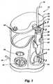
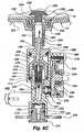
- Fig. 1depicts a perspective view of a first embodiment of an apparatus 10 for providing a pressurized fluid stream.
- the embodimentmay include a base unit 12, which may support a reservoir 14 for storing a fluid such as water.
- a container 16having a container base 18 and a lid 20 may be positioned atop the reservoir 14 and define one or more ventilation holes 22.
- the container 16may be used for storing items, including accessories utilized with the apparatus 10.
- One exemplary accessoryis a tip 24 having an opening for delivering a pressurized fluid stream.
- Such a tip 24may be attached to a handle 26 having a latch 28 that selectively detaches the tip 24 from the handle 26.
- the handle 26may further include a button 30 for pausing fluid flow to the tip 24.
- the handle 26may be removably secured to the base unit 12 via a clamp 32 joined to the base unit 12 and may be coupled to a tube 34 in fluid communication with a pump contained within the base unit 12.
- a power cord 36may connect a power source (not shown) to the pump.
- a switch 38may be connected to the base unit 12 for turning the pump on and off.
- a knob 40may be connected to the pump for adjusting the fluid pressure of a fluid supplied by the pump.
- the knob 40may be, for example, inserted through a knob aperture in the base unit 12 in order to be accessible to an operator.
- Each of the base unit 12, reservoir 14, container 16, tip 24, handle 26, clamp 32, tube 34, switch 38, and knob 40may be composed of plastic, metal, rubber, carbon composites, another suitable material, or some combination thereof.
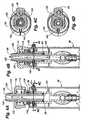
- the handle 26may include a handle housing 48 composed of a first and second housing segment 50, 52.
- the first and second handle housing segments 50, 52together define a cavity 54 in which a valve body 56, the tube 34, and a collar unit 58 may reside.
- the first and second handle housing segments 50, 52may each include first, second, third and fourth interior walls 60, 62, 64, 66 for aligning the valve body 56, the tube 34, and the collar unit 58 within the cavity 54.
- the interior walls 60, 62, 64, 66generally extend in a horizontal plane with respect to the handle 26, and inwardly from one of the first and second housing segments 50, 52. Each interior wall 60, 62, 64, 66 may align with a mating interior wall extending from the opposing housing segment when the handle 26 is assembled.
- the first handle housing segment 50may include a button aperture 68 receiving the button 30.
- the second handle housing segment 52may include one or more L-shaped sidewalls 70 that support the valve body 56 when the button 30 is pressed. Generally, pressing the button 30 forces the valve body 56 against an L-shaped sidewall 70.
- the valve body 56may define a series of fluid passages along its length.
- an inner surface of the valve body 56may define a valve body aperture for receiving a collar unit 58 defining a first fluid passage 72 extending from the first and second handle housing segments 50, 52 to a handle head 74 formed at the top of the handle 26.
- the handle head 74generally receives the tip 24.
- the collar unit 58may include a collar 76 that may encircle at least a portion of the first fluid passage 72.
- the inner surface of the valve body 56may be stepped to define a second fluid passage 78 adjacent to the first fluid passage 72.
- This second fluid passage 78typically has a cross-sectional area at least slightly smaller in at least one dimension than the cross-sectional area of the first fluid passage 72. This change in the cross-sectional area forms a step.
- the stepmay support a valve body O-ring 80, which may prevent pressurized fluid from leaking into the handle housing 48 along the joint formed between the valve body 56 and the collar unit 58.
- the inner surface of the valve body 56may be stepped again to define a third fluid passage 82 adjacent to the second fluid passage 78 having a cross-sectional area smaller in at least one dimension than the cross-sectional area of the second fluid passage 78.
- the inner surface of the valve body 56also may define a fourth fluid passage 84.
- This fourth fluid passage 84may be generally transverse to the first, second, and fluid passages 72, 78, 82. That is, while the first, second and third fluid passages 72, 78, 82 extend along the longitudinal axis of the handle 26, the fourth fluid passage 84 extends along the transverse axis of the handle 26.
- the fourth fluid passage 84generally underlies the button 30 and may receive a stop plunger 86.
- the third fluid passage 82provides a fluid connection between the second 72 and fourth fluid passages 78, 84, while the fourth fluid passage 84 receives the stop plunger 86 for pausing the flow of fluid from the tube 34 to the tip 24 as described in more detail below.
- a pair of tab walls 88may extend from the valve body 56 in a direction generally parallel to the longitudinal axis of the handle 26.
- Each tab wall 88may include a tab aperture 90 sized to receive a tab 92 associated with, or placed on, the collar unit 58.
- an arrowhead shaped wall 94 for receiving the tube 34may extend from the valve body 56 in a direction generally aligned with the handle's 26 longitudinal axis.
- the tube 34When joined to the valve body 56 by the arrowhead shaped wall 94, the tube 34 may fluidly communicate with the fourth fluid passage 84 via an opening 96 in the arrow-head shaped wall 94.
- a tube clamp 98may clamp the portion of the tube's 34 inner surface received by the arrowhead shaped wall 94 against the arrowhead shaped wall's 94 outer surface.
- the first fluid passage 72may extend through the collar unit 58 and into the handle head 74.
- the collar unit wall 100 (or walls, in some embodiments) of the first fluid passage 72may have first, second, and third collar unit projections 102, 104, 106 extending from its outer surface.
- the first collar unit projection 102may include one or more of the aforementioned tabs 92 for connecting the collar unit 58 to the valve body 56 when a portion of the collar unit 58 is received within the valve body 56. As the collar unit 58 is received within the valve body 56, the tabs 92 push the tab walls 88 outwardly until the tabs 92 generally align with the tab apertures 90.
- the second collar unit projection 104may align the collar unit 58 with the first and second handle housing segments 50, 52.
- the collar 76may be composed of the third collar unit projection 106 and a collar sidewall 108 extending from the free end of the third collar unit projection 106 in a direction generally parallel to the longitudinal axis of the handle 26, thereby defining a space 110 between the between the collar sidewall 108 and the outer surface of the collar unit wall 100.
- a first spring 112may be located within the space 110 to maintain a pre-determined distance between a handle head 74 and the handle housing 48 as described in more detail below.
- a fourth collar unit projection 114may extend generally transversely from the free end of the collar sidewall 108, thereby providing a surface for engaging handle head flanges 116 extending inwardly from an inner surface of the handle head 74.
- the inner surface of the handle head 74may define a handle head space 118 receiving the first spring 112.
- the first spring 112may compress to engage the third collar unitprojection 106 and the handle head's 74 inner surface when the handle head 74 and collar unit 58 are joined.
- the first spring 112may exert an upward force against the handle head 74 when compressed. Although this upward force may tend to drive the handle head 74 away from the collar unit 58, engagement between the handle head flanges 116 and the fourth collar unit projection 114 will resist separation of the handle head 74 and collar unit 58 by this upward force.
- the cumulative effect of the upward force by the first spring 112 being resisted by the engagement between the head handle flanges 116 and the fourth collar unit projection 114is that the handle head 74 generally will be maintained at a pre-determined distance from the third collar unit projection 106 of the collar unit 58.
- the handle head 74will generally be maintained at a pre-determined distance from the handle housing 48 as shown in Figs. 2 and 3 .
- the handle head 74may be depressed to be adjacent the handle housing 48. Further, when the handle head 74 is positioned adjacent the handle housing 48, the handle head 74 may be rotated relative to the collar unit 58 around a longitudinal axis of the handle 26 since the handle head 74 is not fixedly connected to the collar unit 58. As described in more detail below, a tip 24 received within the handle head 74 may be rotated around the longitudinal axis of the handle 26 by rotating the handle head 74 around this longitudinal axis, thereby permitting the direction of the fluid stream exiting the tip 24 to be changed by rotating the handle head 74.
- the handle head 74may be depressed into the position shown in Fig. 4B when a tip 24 is received within the handle head's 74 opening and coupled with the latch 28 as described in more detail below.
- the first spring 112compresses further.
- the further compressed first spring 112will exert an upward force, which will return the handle head 74 back to its original pre-determined distance from the handle housing 48 in the absence of another force opposing this upward force.
- this upward forcewill be opposed, thereby maintaining the handle head 74 in a position adjacent the handle housing 48 as shown in Fig. 4B .
- the handle head 74may include a recessed surface 120 encompassing an opening adapted to receive the tip 24 and surrounded by a recessed wall 122.
- the recessed wall 122may define a shape adapted to mate with a tip annular ring 124 extending from an exterior surface of a portion of the tip 24, namely a tip shaft 126.
- the engagement of the recessed wall 122 with the tip annular ring 124may permit the tip 24 to be rotated around a longitudinal axis of the handle 26 as the handle head 74 rotates around the longitudinal axis of the handle 26.
- the latch 28may permit the tip 24 to be selectively attached or detached from the handle 26, and specifically from the handle head 74.
- the latch 28may have a latch body 128 defining a latch aperture 130 that may be received on the collar unit wall 100.
- a latch slot 132may extend from the latch aperture 130 and mate with a collar tongue 134 extending from the collar unit wall 100, thereby providing an alignment mechanism for properly aligning the latch 28 relative to the collar unit 58 when joining the latch 28 and the collar unit 58 as described in more detail below.
- a portion of the latch body 128may be received within a collar opening 136 in the collar unit wall 100. As described in more detail below, this portion of the latch body 128 may mate with a groove 138 in the tip 24, thereby retaining the tip 24 when it is engaged with the handle 26.
- a latch stub 140may extend from the latch body 128 and receive a second spring 142. When the handle 26 is assembled, the second spring 142 will be compressed between the latch body 128 and the handle housing 48 as shown in Fig. 3 . The compressed second spring 142 will exert a force upon the latch 28 that pushes a portion of the latch body 128 into the collar opening 136 as shown in Fig. 3 when a tip 24 is not received within the first fluid passage 72. As described in more detail below, when a tip 24 is received within the first fluid passage 72, the second spring 142 also pushes a portion of the latch body 128 into the tip groove 138, thereby coupling the tip 24 with the latch 28.
- the button 30may be received within the button aperture 68 of the first handle housing segment 50.
- the button 30may include a generally concave and ovoid first surface.
- a lip 144 or other projection extending from a wall 146 of the button 30generally may prevent the button 30 from passing entirely through the button aperture 68 when the button 30 is received therein.
- the button 30may include a stop plunger projection 148 adapted to mate with a stop plunger aperture 150 defined by a stop plunger body 152 to connect the button 30 to the stop plunger 86.
- a glue, epoxy, or other adhesivemay also be used to join the stop plunger 86 to the button 30.
- the stop plunger 86may further include a stop plunger shaft 154 extending from the stop plunger body 152.
- the stop plunger shaft 154may include one or more stop plunger grooves that each may receive a stop plunger O-ring 156.
- the stop plunger O-rings 156may prevent a fluid from leaking into the handle housing 48 of the handle 26 through the joint formed by the stop plunger 86 and the valve body 56.
- the stop plunger O-rings 156may also prevent fluid from the leaking into the first fluid passage 72, or into the handle housing 48 of the handle 26, when the stop plunger 86 is engaged to stop the flow of fluid through the valve body 56 as shown in Fig. 5 .
- the stop plunger 86When the stop plunger 86 is in this closed position, the stop plunger 86 seats within the fourth fluid passage 84, thereby preventing fluid flow from the tube 34 through the fourth fluid passage 84 and, ultimately, through the valve body 56. This, in turn, prevents fluid from flowing into the first fluid passage 72 and any tip 24 connected to the handle head 74.
- a third spring 158may be located between the stop plunger 86 and one or more spring-engaging protrusions 160 formed in the valve body 56.
- the third spring 158is biased to return the stop plunger 86 to an open position when the button 30 is released.
- fluidmay flow through the tube 34, into the valve body 56, and into a tip 24 connected to the handle head 74. Fluid flow through the present embodiment is described in more detail below.
- a tip proximal end 162is inserted into the first fluid passage 72 (the fluid passage through the collar unit 58) through the opening in the handle head 74.
- the portion of the latch body 128 received within the collar opening 136 in the collar unit wall 100engages the tip proximal end 162. This engagement causes the latch body 128 to slide along the sloped surface of the tip proximal end 162, thereby pushing the latch body 128 out of the collar opening 136.
- the second spring 142is compressed between the latch 28 and the handle housing 48 (see Fig. 4A ).
- the tip annular ring 124 formed on the tip exteriorengages the handle head's recessed surface 120. Accordingly, as the tip 24 is pushed, the handle head 74 likewise moves towards the handle housing 48. As the handle head 74 moves towards the handle housing 48, the first spring 112 compresses between the handle head 74 and the collar unit 58.
- the tip groove 138generally aligns with the latch body 128 and collar opening 136 as shown in Fig. 4B .
- the compressed second spring 142pushes a portion of the latch body 128 into the collar opening 136 and the tip groove 138. Receipt of a portion of the latch body 128 within the tip groove 136 couples the tip 24 with the latch 28 thereby attaching the tip 24 to the handle 26.
- a noisemay occur when the latch body 128 is received within the tip groove 138, thereby providing an audible indication that the tip 24 is attached to the handle 26.
- the noisemay be a click, beep, bell, whistle, and so forth.
- the noisemay be mechanically produced (for example, a click resulting from a portion of the tip 24 impacting a portion of the handle 26, or a click resulting from a portion of the tip 24 springing outward or mechanically deforming).
- the noisemay be electronically produced (such as a beep or chime from an electronic speaker activated when the tip 24 is properly seated).
- a segment of the tip 24may, for example, mechanically depress an electronic element to initiate the noise, or may complete an electronic circuit.
- the latch body 128may mechanically depress an electronic element associated with the tip 24 (such as within the tip groove 138) or complete an electronic circuit with the tip 24 when seated in the tip groove 138.
- the latch 28is pressed towards the handle 26.
- the portion of the latch body 128 received within the tip groove 138moves out of the tip groove 138.
- the first spring 112expands.
- the handle head 74moves away from the handle housing 48, thereby returning the handle head 74 to the position occupied prior to insertion of the tip 24. This motion also forces the tip 24 upward.
- the tip groove 138moves upward, and thus is no longer aligned with the latch body 128.
- the tip 24may be removed from the handle 26 since it is no longer coupled to the handle 26 by the latch 28.
- the handle head's return towards its original position prior to insertion of the tip 24provides a visual indication that the tip 24 is no longer coupled to the handle 26 by the latch 28. More particularly, in addition to the motion of the handle head 74, the collar unit 58 appears to expand as the handle head 74 retreats from the handle 26 in order to provide the aforementioned visual indication.
- Fig. 6depicts an exploded perspective view of various components of the embodiment of the handle 26 depicted in Figs. 2, 3 , 4A, 4B , and5.
- the components of the embodimentmay include the first and second handle housing segments 50, 52, the tube 34, the latch 28, the button 30, the handle head 74, the collar unit 58, the valve body 56, the tube clamp 98, the stop plunger 86, the valve body and stop plunger O-rings 80, 156, and the first, second and third springs 112, 142, 158.
- the first and second handle housing segments 50, 52may separate in order to receive the collar unit 58, the latch 28, the body valve 56, the stop plunger 86, the button 30, the second and third springs 142, 158, the tube clamp 98, a portion of the tube 34, and the valve body and stop plunger O-rings 80, 156.
- first, second, third and fourth notches 164, 166, 168, 170 formed in each of the first, second, third and fourth interior walls 60, 62, 64, 66 extending from the first and second handle housing segments 50, 52cooperate to form first, second, third, and fourth handle housing apertures, respectively.
- first, second, third and fourth interior walls 60, 62, 64, 66 of the first handle housing segment 50abut the first, second, third, and fourth interior walls 60, 62, 64, 66 of the second handle housing segment 52
- the semicircular notches 164, 166, 168, 170 in each such interior wallalign with the corresponding notches formed in the mating interior wall.
- each of the aforementioned handle housing aperturesare generally circular in shape, although in alternative embodiments the handle housing apertures may be of any desired shape.
- the first, second, third, and fourth interior walls 60, 62, 64, 66 extending from the interior surfaces of the handle housing segments 50, 52may each have a length generally parallel to the lengths of the other interior walls.
- the interior walls 60, 62, 64, 66may generally be located along the lengths of their respective handle housing segments 50, 52 such that when the first and second handle housing segments 50, 52 are joined, the notches 164, 166 in the first and second interior walls 60, 62 define a pair of co-axially aligned first and second handle housing apertures that may receive the tube 34, and the notches 168, 170 in the third and fourth interior walls 64, 66 define a pair of coaxially aligned third and fourth handle housing apertures that may receive the valve body 56.
- each of the aforementioned fifth, sixth, and seventh handle housing aperturesare generally circular in shape, although in alternative embodiments the handle housing apertures may be of any desired shape.
- the fifth handle housing aperturemay receive the latch 28, the sixth handle housing aperture may receive the collar unit 58, and the seventh handle housing aperture may receive the tube 34.
- One or more pegs 178may extend from the interior surface of the first handle housing segment 50 proximate the first, second, third, and fourth interior walls 60, 62, 64, 66. Each peg 178 may be adapted to mate with a corresponding hole in the second handle housing segment 52. The pegs 178 and the holes may be dimensioned such that each peg 178 will relatively snugly fit within its corresponding hole. The friction resulting from this fit may resist decoupling of the handle housing segments 50, 52.
- first and second housing segments 50, 52may be joined using glue, epoxy, fasteners, sonic welding, any other known method for joining two items, or by a combination of known methods.
- the pegs 178may be glued or adhered within the holes.
- an interior fluid passage 180may be formed within the hollow tube 34.
- the interior passage 180may be dimensioned so that an end portion of the tube 34 may be received on the arrowhead wall 94 of the valve body 56.
- the tube clamp 98may be a generally cylindrical and likewise hollow. The tube clamp 98 may be slid over the exterior surface of the tube 34.
- the handle head 74may include a generally crown-shaped upper surface with one or more recesses 182. A user may rest his or her fingers on or in these recesses 182 to grip the handle head 74 when rotating it around the handle's 26 longitudinal axis.
- the first fluid passage 72is generally cylindrical.
- the first, second, and third collar unit projections 102, 104, 106may be generally annular, and the collar sidewall 108 may be generally annular.
- the latch 28may be composed of a latch key 184, the latch body 128, and the latch stub 140.
- the latch key 184may be a pentagonal structure.
- the latch body and stub 128, 140may each be a rectangular solid.
- the latch aperture 130 defined within the latch body 128may be generally arch-shaped with the straight edge of the arch being partially received within the collar opening 136 located in the collar unit wall 100.
- the stop plunger 86may form an at least partially-circular plane with a cylindrical shaft 154 extending transversely from the planar body 152.
- the tip 24may include an elongated, generally cylindrical shaft 126 that is bent or angled at a distal end 186.
- the inner surface of the tip shaft 126may define a tip fluid passage, which may narrow along the tip shaft's length or at least near the distal end 186.
- the tip shaft 126may include the tip groove 138, which may engage the latch 28 as described above, and the tip annular ring 124, which may extend around the tip shaft's circumference and engage the handle head 74 as described above.
- the first spring 112is received within the annular space 110 defined by the collar sidewall 108 and collar unit wall 100.
- the handle head 74is pressed onto the collar unit 58 until its flanges 116 clear the fourth collar unit projection 114 extending from the collar sidewall 108.
- the handle head flanges 116will abut the fourth collar unit projection 114 and prevent disconnection.
- the collar unit wall 100is inserted through the latch aperture 130 until a surface of the latch body 128 abuts the first collar unit projection 102.
- the second spring 142is received on the latch stub 140.
- valve body O-ring 80is positioned at the end of the first fluid passage 72 opposite the collar unit 58, and the collar unit wall 100 is inserted into the valve body apeture of the valve body 56 until the tabs 92 of the collar unit 58 engage the tab apertures 90 defined in the tab walls 88 of the valve body 56.
- the third spring 158is placed against the valve body 56 and contacts the spring-engaging protrusions 160 of the valve body 56.
- the stop plunger O-rings 156 placed about the stop plunger 86are received within the stop plunger grooves, and the stop plunger 86 is connected to the button 30 and inserted at least partially into the fourth fluid passage 84.
- the tube 34is received on the arrowhead wall 94 extending from the valve body 56 and the tube clamp 98 is slid onto the portion of the tube 34 received by the arrowhead wall 94.
- the valve body 56(with attached components) is placed within the second handle housing segment 52; the first, second, third, and fourth interior walls 60, 62, 64, 66 facilitate locating the valve body 56 and attached components within the second handle housing segment 52.
- the first handle housing segment 50may be joined with the second handle housing segment.
- the previously described methodis merely one exemplary method of assembly. Accordingly, other methods of assembling the handle 26 may be used, including, without limitation, varying the order of some or all of the operations described above.
- Fig. 7depicts a perspective view of the lower left portion of the embodiment depicted in Fig. 1 with the knob 40, the switch 38, a portion of the base unit 12 and a portion of the reservoir 14 removed to show a segment of the pump 200 and a related fluid flow path between the reservoir 14 and the pump 200.
- Fig. 7also depicts a mechanism (described below) for adjusting the fluid pressure delivered to the tip 24 by the pump 200.
- a reservoir valve 202may be connected to a tube stand 204, as described in more detail below.
- the tube stand 204may be connected to a pump inlet body 206, which may be connected to a pump body 208 with fasteners 210 (such as screws).
- a flow control 216may also be connected to the pump body 208 with fasteners 218 such as screws.
- the flow control 216may include a pair of prongs 220 for attaching the knob 40 to the flow control 216.
- a piston 222(received within a piston housing) may be operatively associated with the pump body 208 as described in more detail below.
- the pump body 208may also be connected to a fitting, which may be used to fluidly communicate the tube 34 with the pump 200.
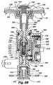
- Fig. 8Adepicts a cross-sectional view of a portion of the pump 200, the base unit 12, and the reservoir 14 viewed along line 8-8 of Fig. 7 .
- the base unit 12may include an upper and a lower base unit segment 224, 226.
- the upper base unit segment 224may include a seat 228 extending from the upper base unit segment 224 into a cavity defined by the mating of the upper and lower base unit segments 224, 226.
- the seat 228may receive the tube stand 204, which typically includes a tube stand shaft 232 defining a tube stand fluid passage 234.
- the tube stand 204may further include a tube stand collar 236 comprised of a tube stand base 238 and defining a tube stand opening in fluid communication with the tube stand fluid passage 234.
- a tube stand sidewall 240extends from the tube stand base 238. Together, the tube stand base and sidewall 238, 240 may fit snugly within the seat 228.
- One or more tube stand projections 242may extend from the tube stand base 238 to contact the reservoir valve 202, which seats within a reservoir opening 244 defined in a reservoir base 246.
- the tube stand projections 242lift a reservoir valve head 248 off the reservoir base 246, thereby enabling fluid to enter and exit the reservoir 14 through the reservoir valve 202 and tube stand fluid passage 234.
- the tube stand 204 and the reservoir valve 202are generally co-axially aligned and the tube stand projections 242 engage a reservoir valve shaft 250. This pushes the reservoir valve head 248 away from the reservoir base 246.
- reservoir valve legs 252 extending from the reservoir valve shaft 250bear against the reservoir base 246.
- the reservoir valve legs 252may be sufficiently flexible to deform under pressure, thereby allowing the reservoir valve head 248 to be lifted, but also dimensioned to prevent the reservoir valve 202 from being entirely pushed out of the reservoir opening 244 in the reservoir base 246 by the tube stand projections 242.
- the deformed reservoir valve legs 252will return to their original state, thereby returning the reservoir valve head 248 to its original position of bearing against the reservoir base 246. Gravity and/or fluid pressure may also aid in returning the reservoir valve head 248 to its original position.
- the tube stand 204may be connected to a portion of the pump inlet body shaft 254, which may be received within the tube stand fluid passage 234.
- the pump inlet body shaft 254may include a first portion received within the tube stand fluid passage 234 and a second portion received within a first aperture of the pump body.
- the first and second portions of the pump inlet body shaft 254are connected by a necking region.
- a pump body inlet flange 256may be formed as a portion of the pump inlet body 206 and may bear against an end surface of the pump body 208.
- An inlet groove formed on an upper portion of the pump inlet body 206may receive a first base O-ring 258.
- the shaft 254may form an inward step in profile.
- this inward step and the pump body's inner surfacemay define a space for receiving a second base O-ring 260.
- the functions of the first and second base O-rings 258, 260are described below.
- the first portion of the pump inlet body shaft 254may define a pump inlet fluid passage 262 in fluid communication with an interior pump chamber 264 defined by the necking region portion and second portion of the pump inlet body shaft 254.
- the pump inlet fluid passage 262may increase in cross-sectional area after the necking region to define the interior pump chamber 264 in which a check valve assembly 266 is located.
- the pump inlet body shaft 254may include a return hole 268 located within the necking region, which may enable fluid communication between the pump inlet fluid passage 262 and a return chamber 270 defined by the combination of pump inlet body's outer surface and the pump body's inner surface.
- the check valve assembly 266may contain a ball 272, a check valve spring 274, a seat relief 276, and a valve cap 278.
- the check valve assembly 266may include a check valve shaft 280, in which the ball 272, check valve spring 274, and seat relief 276 may be positioned.
- the ball 272seats at one end of the check valve shaft 280 (i.e., the end furthest from the pump inlet).
- the check valve shaft 280may include a check valve lip 282 to mate with a valve cap groove defined by the valve cap body, thereby creating a snap-fit connection between the valve cap 278 and the check valve shaft 280.
- valve 278 capmay abut the seat relief 276.
- an internal passageruns through the valve cap interior, providing a fluid connection between the pump inlet fluid passage 262 and the interior of the check valve assembly 266.
- fluid flowing through the internal passage of the valve cap 278may enter the seat relief interior, which is generally hollow. In this manner, fluid may be conveyed from the reservoir 14, through the space between the reservoir valve head 248 and reservoir base 246, into the tube stand fluid passage 234, into the pump body 208 through the pump inlet fluid passage 262, through the valve cap 278 and into check valve shaft 280.
- fluidmay flow between the interior pump chamber 264 and pump body outlet 286.Further, during the piston 222 backstroke, the aforementioned suction generally draws fluid from the interior pump chamber 264 into the pump body outlet 286.
- a forward stroke of the piston 222positive pressure is generated in the pump body outlet 286 (and, by extension, in portions of the present embodiment fluidly connected to the pump body outlet 286).
- This positive pressurehas several effects. First, it forces fluid out of the pump body outlet 286. Fluid may flow through a reed valve 292 (described below), into a bypass valve 294, or push against the check valve base 284. In many cases, fluid flows through two or all three fluid paths simultaneously.
- Fig. 8Adepicts the fluid flow paths available during a forward stroke of the piston 222.
- valve base 284lifting the check valve assembly 266 off the check valve stop 290.
- the pressure of the forward strokeis sufficient not only to unseat the check valve assembly 266 from the check valve stop 290, but to drive the exterior (top) of the valve cap 278 against the interior surface of the interior pump chamber 264.
- the abutment of valve cap 278 and interior pump chamber surfaceforms a substantially fluid-tight seal.
- fluidmay enter the interior pump chamber 264 from the pump body outlet 286 during the piston's forward stroke, the fluid may not enter the pump inlet fluid passage 262 or flow any further towards the reservoir 14.
- Fluidmay also flow through the bypass valve 294 during the piston's forward stroke.
- fluid flowing through the bypass valve 294enters a flow regulation conduit 296 formed on the back of the flow control 216.
- the back of the flow control 216abuts the bypass valve 294.
- Fluid exiting the bypass valve 294 from the pump body outlet 286enters the flow regulation conduit 296.
- the body of the bypass valve 294extends slightly outwardly from the exterior wall of the pump body 208.
- the exterior of the pump body 208 and back of the flow control 216cooperate to form a return channel 298 (see Fig. 8A ) fluidly connected to the flow regulation conduit 296.
- This return channel 298is further fluidly connected to the return chamber 270 formed by the interior surface of the pump body 208 and the pump inlet body 206.
- the return chamber 270is outside the interior pump chamber 264 and in fluid communication with the pump inlet fluid passage 262.
- Fluid flowing through the bypass valve 294 and into the flow regulation conduit 296impacts the back of the flow control 216.
- the fluidforced by the pressure of the piston's forward stroke, is diverted into flow regulation conduit 296 and thence to the return channel 298, from which it may enter the return chamber 270.
- fluidmay flow up the pump inlet fluid passage 262 and into the tube stand fluid passage 234. If the return fluid is under sufficient pressure to overcome the fluid pressure of fluid flowing from the reservoir 14 into the tube stand fluid passage 234 under the influence of gravity, the fluid may flow back into the reservoir 14 through the open reservoir valve 202.
- bypass valve 294permits fluid flow in two directions, namely from the pump body outlet 286 to the return channel 298 and from the return channel 298 to the pump body outlet 286. (That is, the bypass valve 294 is a two-way valve.) Accordingly, fluid may flow from the pump inlet fluid passage 262, into the return chamber 270, down the return channel 298 and into the pump body outlet 286 during the piston's backward stroke.
- the flow control 216may adjust the volume of fluid that may flow through the bypass valve 294 and into the return channel 298. As the flow control 216 is rotated, the dimensions of the flow regulation conduit 296 vary. Essentially, the cross-section of the flow regulation conduit 296 adjacent the bypass valve 294 increases or decreases, depending on the direction in which the flow control 216 is turned. For example, in one embodiment rotating the flow control 216 clockwise (as viewed from the front of the flow control) may decrease the cross-sectional area of the flow regulation conduit 296 adjacent the bypass valve 294, while rotating the flow control counterclockwise may increase the cross-sectional area of the conduit 296. Figs.
- FIGS. 11A-11Cdepict cross sectional views of a portion of the flow control 216 depicting the size of the flow regulation conduit 296 at different points along the conduit's length.
- FIGs. 11A-11Care cross-sectional views viewed along their respective lines shown in Fig. 9 .
- the flow regulation conduit 296 adjacent the bypass valve 294As the dimensions of the flow regulation conduit 296 adjacent the bypass valve 294 increase, more fluid may be accepted from the bypass valve 294 and diverted to the return channel 298. Conversely, as the dimensions of the flow regulation conduit 296 adjacent the bypass valve 294 decrease, the volume of fluid that may exit the bypass valve 294 into the conduit 296 (and return channel 298) likewise decreases. In this manner, a user may adjust the flow volume through the return channel 298 and into the return chamber 270 as desired. As shown in Fig. 8B , the fluid regulation conduit 296 may be adjusted to prevent fluid from exiting the bypass valve 294 into the return channel 298.
- the third fluid exit from the pump body outlet 286is via the reed valve 292 fluidly connected to a fitting 300.
- the fitting 300seats within a pump body base opening 302 formed in the bottom of the pump body 208, as shown in cross-section on Figs. 8A-8C .
- One end of the aforementioned tube 34is connected to a fitting outflow 304, and a fitting fluid path 306 extends from a top of the fitting 300, adjacent the reed valve 292, to the fitting outflow 304. Accordingly, fluid entering the fitting 300 may flow through the fitting outflow 304, into the tube 34, through the handle 26, and ultimately into the tip 24 in order to irrigate or spray fluid into a user's mouth.
- the reed valve 292generally permits fluid flow only when open. As the piston executes a forward stroke, fluid pressure forces the reed valve 292 into an open position. That is, the reed of the reed valve 292 is pushed downward into the fitting fluid path 306. Thus, fluid may be driven by the piston 222 through the reed valve 292, into the fitting fluid path 306, through the associated fitting outflow 304 and into the tube 34. Ultimately, and by means of the tube 34, the piston 222 propels fluid into the tip 24, as well as out of the tip distal end 186.
- adjusting the flow control 216can vary fluid flow out of the pump body outlet 286 and through the return channel 298. It should be appreciated that as more fluid passes to the return channel 298, less fluid is available to enter the fitting fluid path 306 (and tube 34) through the reed valve 292. Accordingly, increasing the flow through the return channel 298 diminishes fluid flow to the tip 24, which decreases the fluid pressure of fluid exiting the tip 24. In this manner, the user may directly control the volume of fluid exiting the reservoir 14 and being pushed by the piston 222 through the tip 24. Thus, the user may control fluid flow out of the tip 24 by manipulating the flow control 216, which enables the user to control the fluid pressure of fluid exiting the tip 24.
- Fluidmay exit the reservoir 14 through the reservoir opening 244 in which the reservoir valve 202 resides, flowing into the tube stand fluid passage 234.
- the fluidmay enter the pump inlet fluid passage 262 from the tube stand fluid passage 234, flow into the interior pump chamber 264 and around the check valve assembly 266, and into the pump body outlet 286.
- the backstroke suctiondraws the check valve assembly 266 down within the interior pump chamber 264 to permit fluid flow between the pump inlet fluid passage 262 and interior pump chamber 264.
- fluidmay be propelled from the pump body outlet 286, through the reed valve 292, into the fitting fluid path 306, through the fitting outlet 304, into the tube 34, through the various fluid passages 72, 78, 82, 84 of the handle 26, into the tip 24, and out of the tip distal end 186.
- the forward pressure of the piston 222may drive the check valve assembly 266 upward within the interior pump chamber 264, seating the valve cap 278 against an interior surface of the pump inlet body 206. This chokes off fluid flow between the interior pump chamber 264 and the pump inlet fluid passage 262.
- some fluidmay be diverted through the bypass valve 294, into the flow regulation conduit 296, along the return channel 298 and into the return chamber 270. This fluid may then enter the pump inlet fluid passage 262, the tube stand fluid passage 234, and ultimately flow, if under sufficient pressure, into the reservoir 14 through the reservoir valve opening.
- the present embodimentincludes a pause mode.
- a pause modeDuring the pause mode, no fluid flows into or out of the tip 24. This may be useful, for example, when a user wishes to pause oral irrigation.
- a user or operatormay depress the button 30 on the handle 26. Depressing the button 30 forces the stop plunger 86 into the fourth fluid passage 84. Because the stop plunger 86 is aligned within the fourth fluid passage 84 and transverse to the direction of fluid flowing into the valve body 56 from the tube 34, motion of the stop plunger 86 is not opposed by the pressure of fluid flowing through the valve body 56 when the button 30 is pressed or released. The base of the stop plunger 86 may abut a sidewall of the fourth fluid passage 84.
- the stop plunger 86may prevent fluid flow into the fourth fluid passage 84 from the tube 34. Since fluid cannot enter the fourth fluid passage 84, any fluid pressure and flow is prevented from reaching the tip 24. Accordingly, fluid cannot exit the tube 34. Further, since the stop plunger 86 is aligned transversely to fluid flowing into the valve body 56 from the tube 34, little or no fluid pressure opposes the closing of the fourth fluid passage 84 by the stop plunger 86.
- the third spring 158is biased to return the stop plunger 86 to its original position when a user stops depressing the button 30. It should be noted that the third spring 158 does not have to exert force against any fluid pressure to return the stop plunger 86 to its initial position, due to the alignment of the plunger 86.
- Depressing the stop plunger 86additionally forces fluid to seek a different exit from the pump body outlet 286, insofar as more fluid cannot flow through the reed valve 292, into the fitting 399 and thence to the tube 34. (Some fluid may so flow after depressing the button 30, but only enough to fill the fitting 300, fitting outflow 304, and tube 34. Once these elements are filled with fluid, additional fluid may not flow along this route.) Further, the fluid flow volume through the return channel 298 is limited by the size of the flow regulation conduit 296.
- the fluidmay flow up into the interior pump chamber 264 and push against the check valve base 284. As previously mentioned, this unseats the check valve assembly 266 from the check valve stop 290. However, if sufficient fluid pressure exists, the fluid may press against the ball 272 in the check valve shaft 280 and drive it against the check valve spring 274. As shown in Fig. 8C , when the fluid pressure exceeds the tension of the check valve spring 274, the ball 272 may unseat from the check valve base 284 and move upward within the check valve shaft 280. When the ball 272 moves sufficiently upward, fluid may flow from the interior pump chamber 264, through the check valve assembly 266, and into the pump inlet fluid passage 262. Ultimately, such fluid may return to the reservoir 14.
- Fig. 9is an exploded perspective view of an unassembled state of the various components depicted in Fig. 8 .
- Fig. 10depicts an exploded perspective view of the pump body 208 and the flow control 216.
- assembly of the pump body 208, fitting 300, check valve assembly 266, flow control 216, bypass valve 294, and certain other elementswill now be described.
- the ball 272, check valve spring 274 and seat relief 276may be placed within the check valve shaft 280 and the valve cap 278 affixed to the check valve shaft 280 to form the check valve assembly 266.
- the second base O-ring 260 and the check valve assembly 266may be placed in the hollow pump body 208. Generally, the second base O-ring 260 abuts the interior pump body wall.
- the first base O-ring 258may fit within an inlet groove 310 formed on an upper, outer portion of the pump inlet body 206.
- the pump inlet body 206may then be mated to the pump body 208, such that a pump inlet body flange 256 rests atop the pump body 208.
- the majority (although not all) of the pump inlet body 206may be received within the hollow interior of the pump body 208.
- An inside wall of the pump inlet body 206forms a sidewall of the interior pump chamber 264, while a stepped interior base of the hollow pump body 208 forms a base of the interior pump chamber 264.
- the base of the pump inlet body groove 310forms a top of the return chamber 270 and the interior wall of the hollow pump body 208 forms a sidewall of the return chamber 270.
- the second base O-ring 260generally prevents fluid from flowing out of the return chamber 270, along the exterior of the pump inlet body 206 and into the pump body outlet 286.
- the first base O-ring 258reduces or stops fluid leakage out of the return chamber 270, along the pump body inlet groove 310 and into atmosphere.
- the pump inlet body 206may be fastened or affixed to the pump body 208 by adhesive, fasteners (screws, bolts or the like), sonic welding, and so forth.
- one screw 210passes through each of two U-shaped protuberances formed on opposing ends of the pump inlet body flange 256. The screws 210 are received in screw holes formed on the pump body 208.
- a fitting O-ring 312may be placed in a fitting groove 314 formed on the fitting exterior.
- the reed valve 292may be placed atop the fitting 300, and the fitting 300, reed valve 292, and fitting O-ring 312 all inserted into the pump body base opening 302.
- the fitting O-ring 312contacts the interior wall of the pump body base opening 302, and reduces or prevents fluid from leaking out of the pump body outlet 286 and along the fitting exterior (see Fig. 8A ).
- Fasteners 316such as screws, an adhesive, and so forth, may hold the fitting 300 to the pump body 208 and within the aforementioned opening 302.
- the fasteners 316may connect the fitting 300 not only to the pump body 208 but also to the piston housing 288.
- the piston housing 288may be formed with the pump body 208 or may be formed separately and affixed thereto.
- the flow control receptacle 318formed on the pump body 208, is generally cylindrical with a flat, circular end wall. This end wall of the flow control receptacle 318 and the back of the flow control 216 combine to define the aforementioned return channel 298. It should be noted the flow control receptacle 318 may be formed integrally with the pump body 208 or may be formed separately and attached thereto.
- a bypass spring 320may be placed within a potion of the bypass valve 294.
- the bypass valve and spring 294, 320may be fitted in a bypass cavity 322 formed in the end wall of the flow control receptacle 318.
- the bypass cavity 322is in fluid communication with the pump body outlet 286, such that fluid may flow into the bypass valve 294 from the pump body outlet 286 when the bypass valve 294 is seated in the bypass cavity 322.
- the flow control 216may consist of multiple parts.
- the flow control 216may include a flow control backplate 324, a first flow control O-ring 326, a second flow control O-ring 328, and a flow control frontplate 330.
- the first flow control O-ring 326may be placed about an exterior groove formed below a neck of the flow control backplate 324.
- the flow control backplate 324may be mated or placed adjacent to the flow control frontplate 330.
- the neck of the flow control backplate 324passes through a central hole in the flow control frontplate 330 and projects outward.
- the flow control backplate and frontplate 324, 330sandwich the second flow control O-ring 328 therebetween, as shown to best effect in the cross-sectional view of Fig. 8A .
- the flow control frontplate 330may be affixed to the flow control receptacle 318, for example by an adhesive, fastener(s), sonic welding, and so forth. Once the flow control frontplate 330 is affixed to the flow control receptacle 318, it generally will not turn or rotate. However, the flow control backplate 324 may freely rotate or turn about at least a portion of its axis, insofar as it is fixedly connected to neither the flow control receptacle 318 nor the flow control frontplate 330.
- a control stop 332may project inwardly from the central hole of the flow control frontplate 330 and rest in a backplate groove 334 formed on or near the neck of the flow control backplate 324 (see Fig. 10 ).
- the flow control backplate 324may rotate until an edge of the backplate groove 334 impacts the control stop 332, which in turn prevents the flow control backplate 324 from rotating further.
- the portion of the flow regulation conduit 296 adjacent the bypass valve 294changes. This, as described above, may vary the fluid flow through the return channel 298.
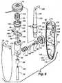
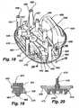
- Fig. 12depicts an exploded, front perspective view of various components of the embodiment depicted in Fig. 1 with portions of the base unit 12 and reservoir 14 removed to better show the reservoir opening 244 in the reservoir base 246 and the seat 228 in the base unit 12.
- the base unit 12may include upper and lower base unit segments 224, 226. When joined, the upper and lower base unit segments 224, 226 may define a cavity for containing the pump 200.
- the upper base unit segment 224may include a basin base 350 and a basin wall 352 extending from the basin base 350, which define a basin 354 for receiving a portion of the reservoir. As described in more detail below, the basin wall 352 may form a unique basin shape, which may facilitate alignment and receipt of the reservoir within the basin 354.
- the basin base 350may include the seat 228 for receiving the tube stand 204.
- a switch aperture 356 to receive the switch 38 and a switch molding 358may be defined in a upper base unit wall 360 of the upper base unit segment 224, and a knob aperture 362 to receive the knob 40 and a knob molding 364 may also be defined in the upper base unit wall 360.
- a tube aperture 366 to receive the tube 34may be defined in the upper base unit wall 360, and clamp slots 368 that receive mating clamp tabs 370 to connect the clamp 32 to the upper base unit segment 224 may be also be defined in the upper base unit wall 360.
- a generally U-shaped power cord groove (not shown) for receiving the power cord 36may also be defined in the upper base unit wall 360.
- a basin rim 372may extend between and join the basin and upper base unit walls 354, 360, thereby providing a bearing surface for the reservoir 14.
- the reservoir 14may include the reservoir base 246 and a reservoir wall 374 extending from the base 246.
- the reservoir base and wall 246, 374may define a volume for storing a fluid such as water.
- the reservoir wall 374may be stepped, thereby defining an upper reservoir wall portion 376 and lower reservoir wall portion 378 connected by a surface for bearing on the basin rim 372 of the upper base unit segment 224.
- the lower reservoir wall portion 378may be received within the basin 354 in the upper base unit segment 224.
- the reservoir wall 374may be outwardly curved along at least a portion of its back side and inwardly curved along at least a portion of its front side (or vice versa).
- These curved portions of the reservoir wall 374typically mate with the basin wall 352 of the upper base unit segment 224.
- the different curved shapes of the front and back sides of the reservoir 14 and basin 354generally ensure the reservoir 14 is aligned in a particular manner when received within the basin 354 of the upper base unit segment 224. This alignment may aid in placing the reservoir valve 202 above or adjacent to the tube stand 204.
- the reservoir 14 and basin 354are described as having differently curved front and back surfaces, other shapes (e.g., such as trapezoidal, angled, scalene triangular, etc.) could be utilized. Any combination of shapes which uniquely permit the reservoir 14 and basin 354 to align in a single manner may be used.
- the tube stand 204may include a generally cylindrical tube stand shaft 232 with a generally partial-conical tube stand collar 236 formed on an end of the tube stand shaft 232.
- the reservoir valve 202may include a generally cylindrical reservoir valve shaft 250 with a generally circular reservoir valve head 248 formed on an end of the reservoir valve shaft 250.
- the circular reservoir valve head 250may encompass the reservoir opening 244 in the reservoir base 246, thereby substantially preventing a fluid from flowing through the reservoir opening 244 when the reservoir valve head 248 bears against the reservoir base 246.
- the reservoir valve 202may also include four generally cubic shaped reservoir legs 252 extending from the reservoir valve shaft 250.
- the switch molding 358may include generally ovoid shaped body.
- the switch molding 358may be attached to the base unit 12 using glue, epoxy, fasteners, sonic welding, or any other suitable known method of joining two items.
- the switch molding 358may define a switch molding aperture 380 to receive the switch 38.
- the switch molding 358may further include a switch molding column 382 extending across the switch molding aperture 380 to mate with a pair of notched, parallel walls extending from a V-shaped body of the switch 38.
- the switch 38may pivot around the switch molding column 382, thereby enabling the switch 38 to move a pump switch connector 384 that turns the pump 200 on and off as described in more detail below.
- the switch 38may be joined to the pump switch connector 384 by receiving a circular switch arm, which is connected to the switch 38 via a switch shaft extending from the switch 38, within a switch connector slot defined by the switch connector's body.
- the knob molding 364may have a generally cylindrical body adapted to be received within the knob aperture 362 of the upper base unit segment 224.
- the knob molding 364may be attached to the base unit 12 in a manner similar to the one described above for the switch molding 358.
- the knob molding 364may define a knob molding aperture 386 to receive the knob 40.
- the knob 40may have a generally cylindrical body adapted to permit the knob 40 to rotate within the knob molding aperture 386 when received therein.
- the knob 40may further include a pair of recessed surfaces defining an elongated knob wall on one side, which may be gripped for rotating the knob 40.
- the knob 40may be connected to the flow control 216 using the flow control prongs 220 extending from the flow control 216. Rotating the knob 40 within the knob molding aperture 386 will rotate the flow control 216, thereby permitting a user to selectively adjust the fluid pressure delivered by the pump 200 to the tip 24.
- the fitting 300may include the fitting outflow 304, which mates with the tube 34.
- the fitting 300may be connected to the pump 200 or the base unit 12 using fasteners 316, thereby enabling the fitting 300 to be selectively detached from the pump 200. Because the fitting 300 may be selectively detached from the pump 200, the handle 26 may be readily decoupled from the pump 200, thereby enabling replacement of the handle 26, if desired.
- the container 16includes the lid 20 and the container base 18.
- the lid 20 and the container base 18may be joined by receiving generally cylindrical lid shafts 390 between generally parallel container base walls 400 extending from container base 18 and configured to receive the lid shafts 390 therebetween, thereby forming a hinge that permits the lid 20 to be rotated relative to the container base 18 around a rotational axis defined by the longitudinal axis of the lid shafts 390.
- the container 16may be opened and closed by rotating the lid 30 relative to the container base 18 around the rotational axis. When closed, inner surfaces of the lid 20 and the container base 18 define an enclosed volume capable of storing items such as tips 24.
- the lid 20 and the container base 18may each have one or more ventilation holes 22, 404 within their respective bodies for ventilating the container 16 when it is closed, which may help dry any wet items placed within the contained and reduce moisture accumulation within the container 16, thereby reducing the potential growth of bacteria within the container 16.
- One or more container tip walls 406may extend from an upper container base surface 408 of the container base 18 and may be configured to accept a tip 24 (see Fig. 12 ) between adjacent container tip walls 406.
- One or more generally cylindrical container tip columns 410may extend from the upper container base surface 408.
- the container tip columns 410may have diameters approximately matching the diameter of the tip fluid passage, thereby supporting the tip 24 in a generally vertical orientation when receiving a container tip column 410 within the tip fluid passage.
- the container base 18has a stepped lower container base surface, thereby defining a container base bearing surface around the perimeter of the container base 18 for bearing on the reservoir 14 and a container base reservoir surface to be received within the reservoir opening.
- a container base rear wall 414may extend from the container base bearing surface proximate the container hinge and generally parallel the container base lower wall 416 separating the container base bearing and container base reservoir surfaces. When the container 16 is supported on the reservoir, the container base rear wall 414 may be generally adjacent and parallel to the exterior surface of the reservoir wall 374, thereby aiding in the opening of the container 16 by bearing against this surface when the container 16 is opened by rotating the lid 20 relative to the container base 18.
- Fig. 14is a perspective view of the embodiment depicted in Fig. 1 with the upper base unit segment 224, the reservoir 14, the container 16, the handle 26, and the power cord 36 not shown to better show the pump 200 connected to the lower base unit segment 226.
- Fig 18is similar to Fig. 14 except all components of the pump 200, other than the pump chassis 420, have been removed to better show the pump chassis 420.
- the pump 200may be connected to the lower base unit segment 226 by pump mounts 422.
- the pump 200may include the pump chassis 420, the pump body 208, a bobbin assembly 424, a stator assembly 426, a rotor 428, first and second gears 430, 432, the piston 222, a bracket 434, and the pump switch connector 384.
- the pump chassis 420may be used to support and align the various components of the pump 200.
- the pump chassis 420may include pump chassis posts 436 that support the stator assembly 426, and may include pump chassis holes 438 (see Fig. 18 ) for receiving fasteners that connect the pump body 208 to the pump chassis 420.
- the stator assembly 426may support the bobbin assembly 424, which may include a switch housing 440 for receiving the pump switch connector 384 operatively associated with the switch 38.
- the stator assembly 426may receive the rotor 428 within a stator aperture.
- the first gear 430may be connected to the rotor 428, and the second gear 432 may engage the first gear 430.
- the piston 222may be connected to the second gear 432 by a second gear shaft (not shown) extending from the second gear 432.
- the longitudinal axis of the second gear shaftmay be eccentric to the axis about which the second gear 432 rotates.
- the piston 222may be received within the piston housing 288 connected to the pump body 208.
- the pump body 208may be connected to the pump chassis 420 with fasteners that are passed through the various u-shaped half-slots extending from the pump body 208 and received in pump chassis threaded holes 438 (see Fig. 18 ) defined in the pump chassis 420.
- the pump inlet body 206may be connected to the pump body 208 using fasteners 210.
- the bracket 434may be used to connect the stator assembly 426 to the pump chassis 420.
- fasteners 44may be received within holes in the bracket 434. These bracket holes are typically co-axially aligned with stator holes in the stator assembly 426, as well as with pump chassis post apertures formed in two of the pump chassis posts 436 supporting the stator assembly 426, as shown in Fig. 18 .
- the stator assembly 426may be clamped between the pump chassis posts 436 and the bracket 434.
- a first alignment shaft(not shown) may run from the pump chassis 420 to the bracket 434 through the rotor 428 and first gear 430 in order to cause the rotor 428 and first gear 430 to rotate around the first alignment shaft's longitudinal axis.
- a second alignment shaft(not shown) may extend through a second alignment hole in the pump chassis 420 and through the second gear 432 in order to cause the second gear 432 to rotate around the second alignment shaft's longitudinal axis.
- Fig. 15depicts a top view of the pump chassis 420 showing first and second alignment shafts 444, 446.
- Fig. 16depicts a bottom view of the pump chassis 420 showing an eccentric end plate 448 connected to the pump chassis 420.
- the centerline of the second alignment shaft 446may be eccentric to the center of the second alignment hole 450. This may allow the second gear 432 to be adjusted relative to the first gear 430, as described in more detail below.
- a distal end of the second alignment shaft 446may be received within a shaft receiving hole 452 formed in an extension of the eccentric end plate 448.
- the center of the shaft receiving hole 452may be offset from the center of the eccentric end plate extension 454.
- this offsetcauses the center of the shaft receiving hole 452 to be likewise offset from the center of the second alignment hole 450 when the eccentric end plate extension 454 is received within the second alignment hole 450.
- the centerline of the second alignment shaft's longitudinal axiswhich coincides with the center of the shaft receiving hole 452, is offset from the center of the second alignment hole 450.
- the eccentric end plate 448may be connected to the pump chassis 420 by fasteners 456 received within pump chassis end plate holes through end plate slotted holes 458.
- the end plate slotted holes 458may be spaced around the perimeter of the circular eccentric end plate 448.
- the eccentric end plate 448may be rotated to multiple positions around the second alignment hole 450 while permitting the eccentric end plate 448 to be connected to the pump chassis 420.
- the location of the centerline of the second alignment shaft 446may be varied relative to the center of the second alignment hole 450.
- the eccentric end plate 448may be turned, which also rotates the second alignment shaft 446 within the second alignment hole 450. This changes the location of the second alignment shaft's longitudinal axis within the second alignment hole 450 and the location of the first gear 430 relative to the second gear 430.
- the first alignment shaft 444remains in a fixed position relative to the center of the second alignment hole 450.
- the first gear 430remains in a fixed position relative to the center of the second alignment hole 450.
- changing the relative position of the second alignment shaft's longitudinal axis relative to the center of the second alignment hole 450changes the relative position of the second alignment shaft 446 relative to the first gear 430.
- changing the position of the second alignment shaft 446 relative to the first alignment shaft 444also adjusts the relative position of the second gear 432 and the first gear 430, thereby permitting the gear mesh between the first and second gears 430, 432 to be adjusted.
- Adjusting the gear meshmay help reduce pump noise and wear on the first and second gears 430, 432, insofar as the gear mesh may be finely controlled in order to avoid being too tight or too loose.
- a sound metermay be used to determine when the second gear 432 has been adjusted to change the mesh between the first gear 430 and second gear 432.
- a better gear mesh positionmay be obtained by rotating the eccentric end plate 448 until the first and second gears 430, 432 stick together, then slightly backing off this position until the first and second gears 430, 432 can move independently of each other in a vertical direction.
- Operation of the pump 200 depicted in Fig. 14involves moving the switch 38 from the off position to the on position.
- the arm connected to the pump switch connector 384causes the pump switch connector 384 to move from a first position to a second position within the switch housing 440, thereby closing an electrical circuit with the bobbin assembly 424.
- Closing the electrical circuitpermits electrical power from a power source to be supplied to the bobbin assembly 424 via the power cord 36 connected to the bobbin assembly 424.
- an electromagnetic fieldcauses the rotor 428 to rotate around the first alignment shaft 444, thereby also rotating the first gear 430 around the first alignment shaft 444.
- the knob 40which may be connected to the flow control 216, may be used to adjust the fluid pressure supplied to the tip 24 by the pump 200.
- the pump 200may vibrate, thereby generating undesired noise.
- the pump mounts 422 connecting the pump 200 to the lower base unit segment 226may be used to reduce pump vibration.
- the pump 200may be connected to the lower base unit segment 226 using five pump mounts 422 positioned at corners of the pump chassis 420. Although five pump mounts 422 are shown, more or less may be used.
- the pump mounts 422may be composed of rubber or other suitable vibration dampening material.
- Fig. 19is a cross-sectional view showing the connections between the pump chassis 420, a pump mount 422, and lower base unit segment 226.
- the pump mount 422may include a mount body 460 defining a mount aperture 462 for receiving a corner of the pump chassis 420.
- the pump mount 422may further include a mount shaft 464 extending from the mount body 460.
- a mount head 466may be formed, which may generally resemble the profile of a trapezoid with the longer base of the trapezoidal adjacent to the end of the mount shaft 464.
- the mount shaft and head 464, 466may be received through a mount connection hole 468 defined in lower base unit segment 226.
- the trapezoidal profile of the mount head 466 in which shorter side is first received within the mount connection hole 468enables the mount head 466 to be pushed through the mount connection hole 468 while also generally preventing the mount head 466 from passing back through the mount connection hole 468, thereby maintaining the connection between the pump mount 422 and the lower base unit segment 226.
- the pump chassis 420may generally be supported a select distance above the lower base unit segment 226.
- the mount body 460may be generally cubic shaped with one corner rounded.
- the mount shaft 464may be generally cylindrical shaped , and the mount head 466 may generally resemble a partial conical shape.
- Footings 470may be used to elevate the outer surface of the lower base unit segment 226 above a surface upon which the lower base unit segment 226 may be supported. Further vibration reduction for the pump 200 may be obtained by use of footings 470 composed of rubber or other suitable vibration dampening material.
- Fig. 20is a cross-sectional view , viewed along line 20-20 in Fig. 18 ,-17 showing the connection between a footing 470 and the lower base unit segment 226.
- the footing 470may include a footing body 472 received within a footing aperture 474 defined by lower base unit segment 226. Similar to the pump mount 422, a footing shaft 476 ending in a trapezoidal profile shaped end may extend from the footing body 472.
- the footing 470may be connected to the lower base unit segment 226 in a manner similar to that described for the pump mount 422. As shown in Fig. 20 , the footing 470 may extend outwardly beyond the footing aperture 474 defined in the lower base unit segment 226, thereby providing a distance between the bearing surface of the footing 470 and the outer surface of the lower base unit segment 226. This distance may result in the lower base unit segment 226 being elevated above the surface upon the footing 470 contacts.
- the footing body 472may be generally cylindrical and may include a recessed surface from which a generally circular footing wall 478 may extend.
- each lower base unit column 480may extend from the lower base unit segment 226.
- Each lower base unit column 480may include a lower base unit column hole 482 for receiving a fastener that may be used to join the upper and lower base unit segments 224, 226 together.
- Each lower base unit column 480may be configured to generally co-axially align with a upper base unit column in the upper base unit segment 224 when the upper and lower base unit segments 224, 226 are joined.
- a U-shaped power cord structure 484 for aligning the power cord 36 with a power cord opening in the upper base unit segment 224may extend from the lower base unit segment 226.
- One or more pump alignment walls 486 for aligning the pump chassis 420 within the base unit 12may also extend from the lower base unit segment 224, and a generally arch-like shell structure 488 defining a partially enclosed tube retainer space 490 for receiving the coiled portion of the tube 34 may extend from the lower base unit segment 226.
- Operation of the embodiment depicted in Figs. 1-20involves filling the reservoir 14 with a fluid (such as water) and supporting the filled reservoir 14 on the base unit 12. Once the filled reservoir 14 is supported by the base unit 12, fluid may flow through the opened reservoir valve 202 in the reservoir 14 to the pump body 208 as described above.
- a fluidsuch as water
- the pump 200may be activated using the switch. Once activated, the piston 222 will supply pressurized to the tip 24 as described above.
- the button 30If the button 30 is engaged during operation of the pump 200, fluid will be prevented from flowing from the tube 34 to the tip 24 as described above, thereby causing the build-up of fluid pressure within the system. This fluid pressure may be relieved by permitting fluid, that otherwise would flow to the tip 24, to flow back to the reservoir 14. As described in more detail above, the fluid pressure will unseat the ball located within the check valve assembly 266, thereby permitting fluid to flow back into the reservoir 14 through the fluid passages in the check valve assembly 266, the pump inlet body 206 and the tube stand 204. When the button 30 is released, the ball 272 reseats within the check valve assembly 266, and the system resumes operation as described above.
Landscapes
- Health & Medical Sciences (AREA)
- Epidemiology (AREA)
- Life Sciences & Earth Sciences (AREA)
- Animal Behavior & Ethology (AREA)
- General Health & Medical Sciences (AREA)
- Public Health (AREA)
- Veterinary Medicine (AREA)
- Dentistry (AREA)
- Engineering & Computer Science (AREA)
- Oral & Maxillofacial Surgery (AREA)
- Water Supply & Treatment (AREA)
- Mechanical Engineering (AREA)
- General Engineering & Computer Science (AREA)
- Pain & Pain Management (AREA)
- Physical Education & Sports Medicine (AREA)
- Rehabilitation Therapy (AREA)
- Infusion, Injection, And Reservoir Apparatuses (AREA)
- Dental Tools And Instruments Or Auxiliary Dental Instruments (AREA)
- Massaging Devices (AREA)
- Brushes (AREA)
Description
- The present invention relates generally to oral hygiene products, and more particularly to a dental water jet unit, a container for storing items, a water dental jet handle, an apparatus for adjusting a fluid pressure and a water dental jet unit pump.
- Harmful bacteria often grows deep between teeth and below the gum line. Traditional toothbrush and flossing often cannot reach these areas to remove the bacteria and food debris from these areas. To overcome the limitations of toothbrushes and flossers, a dental water jet may provide a pressurized water stream to remove trapped debris and harmful bacteria from areas not easily reached by a toothbrush or flosser. Such a dental jet unit typically consists of a pump supplying pressurized water from a water reservoir to a tip. The tip has an opening that permits the pressurized water stream to be directed to the desired locations within the mouth.
- However, in many such dental water jets, the reservoir holding the water to be pressurized and provided to the tip must be mated with a base of the water jet unit by inverting the reservoir and attaching the base thereto. This is typically so because the opening by which the reservoir is filled doubles as the opening through which water may exit the reservoir to be moved by the pump.
- The pumps used in dental jet units for providing the necessary water pressures to effectively remove food debris and bacteria are often noisy. Although the noise does not affect the dental jet's effectiveness at removing food debris and bacteria, it is often unpleasant for the user.
- Further, many dental water jets may not provide any visual indication when a tip is properly seated or mated with the dental water jet (typically within a handle). Similarly, many dental water jets may not visually indicate when the tip is properly removed. Thus, users of such dental water jets may not fully seat the tip, leading to ineffective or weakened oral irrigation. Additionally, the water may leak into the atmosphere between the interface of the improperly-seated tip and the handle. Further, users of such water jets may experience difficulty fully removing the tip from the handle.
- Although some dental water jets permit a user to adjust the flow of fluid from the reservoir to the tip, many do not provide fine fluid flow control. Others have discrete settings as opposed to permitting a user to fine-tune fluid flow.
US5,086,756 discloses a device for irrigating an oral cavity with liquid from a container which includes a discharge nozzle and a hand operated pump unit. The container is provided with a female module having a specifically configured opening to accept a male module on the pump unit with the modules including interlocking components which are engaged and disengaged by partial rotation and including a seal which provides a leak proof communication between the interior of the container and the pump unit. The container includes an upper end portion that is openable and separate from the liquid containing portion to provide a storage area for the pump unit.US4,078,558 discloses an apparatus for personal hygiene which includes a reservoir removably fitted on a casing for containing a liquid supply, and furthermore, a structure is provided for receiving a dispenser of a hygienic therapeutic product. The dispenser structure can be independently formed and mounted on the apparatus casing or can be incorporated into the reservoir structure. The apparatus consists of a casing which has a lateral projecting part defining a shelf adapted to receive a removable reservoir. On one of its lateral faces, this reservoir has an overflow slot. A lid is connected by a hinge to the reservoir. The reservoir further has, in its lower part, a known type of valve which connects with the pump of the apparatus.- For these and other reasons, there is room in the art for an improved dental water jet.
- The invention is set out in the
independent claim 1. Preferred or optional features are set out in the dependent claims. - Embodiments, features, and operations of the invention will be apparent to those skilled in the art upon reading the following disclosure, together with the accompanying drawings, in which:
Fig. 1 depicts a perspective view of a first embodiment of an apparatus for providing a pressurized fluid stream.Fig. 2 depicts a cross-sectional view of the handle depicted inFig 1 , viewed along line 2-2 inFig. 1 .Fig. 3 depicts a cross-sectional view of the handle depicted inFig 1 , viewed along line 3-3 inFig. 1 .Fig. 4A depicts a portion of the cross-sectional view of the handle shown inFig 3 showing a tip being inserted or removed from the handle.Fig. 4B depicts a portion of the cross-sectional view of the handle shown inFig 3 showing a tip coupled to the handle.Fig. 4C depicts a cross-sectional view of the handle and tip shown inFig. 4A , viewed alongline 4C-4C inFig. 4A .Fig. 4D depicts a cross-sectional view of the handle and tip shown inFig. 4B , viewed alongline 4D-4D inFig. 4B .Fig. 5 depicts a portion of the cross-sectional view of the handle shown inFig 2 , showing a tip attached to the handle and the handle's button pressed to pause the flow of fluid from the tube to the tip.Fig. 6 depicts an exploded perspective view of the handle depicted inFig 1 .Fig. 7 depicts a perspective view of the lower left portion of the embodiment depicted inFig. 1 with the knob, the switch, and a portion of the base unit and the reservoir removed to show a segment of the pump and a related flow path between the reservoir and the pump.Fig. 8A depicts a first cross-sectional view of the pump body and various components depicted inFig 7 , viewed along line 8-8 inFig. 7 , and showing the flow paths of a fluid during the forward stroke of a piston.Fig. 8B depicts a second cross-sectional view of a portion of the pump, the base unit and the reservoir viewed along line 8-8 inFig. 7 , and showing the flow paths of a fluid during a backstroke of the piston.Fig. 8C depicts a third cross-sectional view of a portion of the pump, the base unit and the reservoir viewed along line 8-8 inFig. 7 , and showing fluid flow during a pause operation of the embodiment.Fig. 9 depicts an exploded perspective view of the pump body and flow control depicted inFig. 8 .Fig. 10 depicts an exploded perspective view of the flow control depicted inFig. 9 .Fig. 11A depicts a cross-section view of a portion of the flow control, taken alongline 11A-11A inFig. 9 .Fig. 11B depicts a cross-section view of a portion of the flow control, taken alongline 11B-11B inFig. 9 .Fig. 11C depicts a cross-section view of a portion of the flow control, taken alongline 11C-11C inFig. 9 .Fig. 12 depicts an exploded, front perspective view of various components of the embodiment depicted inFig. 1 Fig. 13 depicts an exploded, perspective view of the container depicted inFig. 1 .Fig. 14 depicts the embodiment shown inFig. 1 with the upper base unit segment, the reservoir, the container, the handle, the tip, and the power cord not shown to better show the pump connected to the lower base unit segment.Fig. 15 depicts a top view of the pump chassis showing the first and second alignment shafts.Fig. 16 depicts a bottom view of the pump chassis showing an eccentric end plate connected to the pump chassis.Fig. 17 depicts a perspective view of the eccentric end plate shown inFig. 16 .Fig. 18 is similar toFig. 14 except all components of the pump, other than the pump chassis, have been removed to better show the pump chassis.Fig. 19 is a cross-sectional view taken depicting the relationship between the pump chassis, mount, and lower housing segment of the embodiment of Fig. , viewed along line 19-19 ofFig. 18 ,Fig. 20 is a cross-sectional view taken showing the connection between a footing and the lower base unit segment of the embodiment of Fig., viewed along line 20-20 ofFig. 18 .- One embodiment takes the form of an apparatus for providing a pressurized water stream for cleaning gums and teeth. The embodiment includes a base unit defining a cavity. The cavity contains a pump, which may move pressurized water from a reservoir to a tip in fluid communication with the pump. The reservoir may be supported on the base unit and in fluid communication with the pump. The pump may be connected to an electrical power source in order to power the pump. The pump may be turned on and off using a switch. A flow control knob may be turned to selectively adjust the water pressure supplied by the tip between a minimum and a maximum value. The reservoir may be removed from the base unit so that it may be filled with a fluid, such as water, from a fluid source (such as a water faucet). The reservoir may support a container for storing tips or other items.
- Fluid may flow from the reservoir, through the base supporting the reservoir, along a tube, from the tube into the handle, and into the tip. The fluid may be propelled by a motive source, such as a piston, to facilitate this flow. Fluid may ultimately be ejected from the tip and into the mouth of a user (for example) to provide oral irrigation and/or cleaning of the teeth, gums, and tongue.
Fig. 1 depicts a perspective view of a first embodiment of anapparatus 10 for providing a pressurized fluid stream. The embodiment may include abase unit 12, which may support areservoir 14 for storing a fluid such as water. Acontainer 16 having acontainer base 18 and alid 20 may be positioned atop thereservoir 14 and define one or more ventilation holes 22. Thecontainer 16 may be used for storing items, including accessories utilized with theapparatus 10. One exemplary accessory is atip 24 having an opening for delivering a pressurized fluid stream. Such atip 24 may be attached to ahandle 26 having alatch 28 that selectively detaches thetip 24 from thehandle 26. Thehandle 26 may further include abutton 30 for pausing fluid flow to thetip 24. Thehandle 26 may be removably secured to thebase unit 12 via aclamp 32 joined to thebase unit 12 and may be coupled to atube 34 in fluid communication with a pump contained within thebase unit 12. Apower cord 36 may connect a power source (not shown) to the pump. Aswitch 38 may be connected to thebase unit 12 for turning the pump on and off.- Additional controls may be used beyond the
aforementioned switch 38. For example, aknob 40 may be connected to the pump for adjusting the fluid pressure of a fluid supplied by the pump. Theknob 40 may be, for example, inserted through a knob aperture in thebase unit 12 in order to be accessible to an operator. Each of thebase unit 12,reservoir 14,container 16,tip 24, handle 26,clamp 32,tube 34,switch 38, andknob 40 may be composed of plastic, metal, rubber, carbon composites, another suitable material, or some combination thereof. Fig. 2 depicts a cross-sectional view of thehandle 26 viewed along line 2-2 inFig. 1 , whileFig. 3 depicts a cross-sectional view of thehandle 26 viewed along line 3-3 inFig. 1 . With reference to these figures, thehandle 26 may include ahandle housing 48 composed of a first andsecond housing segment handle housing segments cavity 54 in which avalve body 56, thetube 34, and acollar unit 58 may reside. The first and secondhandle housing segments interior walls valve body 56, thetube 34, and thecollar unit 58 within thecavity 54. Theinterior walls handle 26, and inwardly from one of the first andsecond housing segments interior wall handle 26 is assembled.- The first
handle housing segment 50 may include abutton aperture 68 receiving thebutton 30. Similarly, the secondhandle housing segment 52 may include one or more L-shapedsidewalls 70 that support thevalve body 56 when thebutton 30 is pressed. Generally, pressing thebutton 30 forces thevalve body 56 against an L-shapedsidewall 70. - The
valve body 56 may define a series of fluid passages along its length. In particular, an inner surface of thevalve body 56 may define a valve body aperture for receiving acollar unit 58 defining afirst fluid passage 72 extending from the first and secondhandle housing segments handle head 74 formed at the top of thehandle 26. (As explained below, thehandle head 74 generally receives thetip 24.) Thecollar unit 58 may include acollar 76 that may encircle at least a portion of thefirst fluid passage 72. - Additionally, the inner surface of the
valve body 56 may be stepped to define asecond fluid passage 78 adjacent to thefirst fluid passage 72. This secondfluid passage 78 typically has a cross-sectional area at least slightly smaller in at least one dimension than the cross-sectional area of thefirst fluid passage 72. This change in the cross-sectional area forms a step. The step may support a valve body O-ring 80, which may prevent pressurized fluid from leaking into thehandle housing 48 along the joint formed between thevalve body 56 and thecollar unit 58. - The inner surface of the
valve body 56 may be stepped again to define athird fluid passage 82 adjacent to thesecond fluid passage 78 having a cross-sectional area smaller in at least one dimension than the cross-sectional area of thesecond fluid passage 78. The inner surface of thevalve body 56 also may define afourth fluid passage 84. This fourthfluid passage 84 may be generally transverse to the first, second, andfluid passages fluid passages handle 26, thefourth fluid passage 84 extends along the transverse axis of thehandle 26. Thefourth fluid passage 84 generally underlies thebutton 30 and may receive astop plunger 86. Thethird fluid passage 82 provides a fluid connection between the second 72 and fourthfluid passages fourth fluid passage 84 receives thestop plunger 86 for pausing the flow of fluid from thetube 34 to thetip 24 as described in more detail below. - At a first end of the valve body 56 (i.e., the end of the
valve body 56 wherein thefirst fluid passage 72 is formed), a pair oftab walls 88 may extend from thevalve body 56 in a direction generally parallel to the longitudinal axis of thehandle 26. Eachtab wall 88 may include atab aperture 90 sized to receive atab 92 associated with, or placed on, thecollar unit 58. At a second end of the valve body 56 (i.e., the end of thevalve body 56 adjacent the fourth fluid passage 84), an arrowhead shapedwall 94 for receiving thetube 34 may extend from thevalve body 56 in a direction generally aligned with the handle's 26 longitudinal axis. When joined to thevalve body 56 by the arrowhead shapedwall 94, thetube 34 may fluidly communicate with thefourth fluid passage 84 via anopening 96 in the arrow-head shapedwall 94. Atube clamp 98 may clamp the portion of the tube's 34 inner surface received by the arrowhead shapedwall 94 against the arrowhead shaped wall's 94 outer surface. - The
first fluid passage 72 may extend through thecollar unit 58 and into thehandle head 74. The collar unit wall 100 (or walls, in some embodiments) of thefirst fluid passage 72 may have first, second, and thirdcollar unit projections collar unit projection 102 may include one or more of theaforementioned tabs 92 for connecting thecollar unit 58 to thevalve body 56 when a portion of thecollar unit 58 is received within thevalve body 56. As thecollar unit 58 is received within thevalve body 56, thetabs 92 push thetab walls 88 outwardly until thetabs 92 generally align with the tab apertures 90. Once aligned, thetabs 92 are received with the tab apertures 90, thereby allowing thetab walls 88 to return to their original position, and thus retain thetabs 92 within the tab apertures 90. Retention of thetabs 92 within the tab apertures 90 results in thecollar unit 58 and thevalve body 56 being connected. The secondcollar unit projection 104 may align thecollar unit 58 with the first and secondhandle housing segments collar 76 may be composed of the thirdcollar unit projection 106 and acollar sidewall 108 extending from the free end of the thirdcollar unit projection 106 in a direction generally parallel to the longitudinal axis of thehandle 26, thereby defining aspace 110 between the between thecollar sidewall 108 and the outer surface of thecollar unit wall 100. - A
first spring 112 may be located within thespace 110 to maintain a pre-determined distance between ahandle head 74 and thehandle housing 48 as described in more detail below. A fourthcollar unit projection 114 may extend generally transversely from the free end of thecollar sidewall 108, thereby providing a surface for engaginghandle head flanges 116 extending inwardly from an inner surface of thehandle head 74. - The inner surface of the
handle head 74 may define ahandle head space 118 receiving thefirst spring 112. Thefirst spring 112 may compress to engage thethird collar unitprojection 106 and the handle head's 74 inner surface when thehandle head 74 andcollar unit 58 are joined. Thefirst spring 112 may exert an upward force against thehandle head 74 when compressed. Although this upward force may tend to drive thehandle head 74 away from thecollar unit 58, engagement between thehandle head flanges 116 and the fourthcollar unit projection 114 will resist separation of thehandle head 74 andcollar unit 58 by this upward force. Further, the cumulative effect of the upward force by thefirst spring 112 being resisted by the engagement between thehead handle flanges 116 and the fourthcollar unit projection 114 is that thehandle head 74 generally will be maintained at a pre-determined distance from the thirdcollar unit projection 106 of thecollar unit 58. Thus, when the joinedcollar unit 58 and handlehead 74 are positioned adjacent with thehandle housing 48, thehandle head 74 will generally be maintained at a pre-determined distance from thehandle housing 48 as shown inFigs. 2 and 3 . - As shown in
Fig. 4B , thehandle head 74 may be depressed to be adjacent thehandle housing 48. Further, when thehandle head 74 is positioned adjacent thehandle housing 48, thehandle head 74 may be rotated relative to thecollar unit 58 around a longitudinal axis of thehandle 26 since thehandle head 74 is not fixedly connected to thecollar unit 58. As described in more detail below, atip 24 received within thehandle head 74 may be rotated around the longitudinal axis of thehandle 26 by rotating thehandle head 74 around this longitudinal axis, thereby permitting the direction of the fluid stream exiting thetip 24 to be changed by rotating thehandle head 74. - The
handle head 74 may be depressed into the position shown inFig. 4B when atip 24 is received within the handle head's 74 opening and coupled with thelatch 28 as described in more detail below. As thehandle head 74 is depressed towards thehandle housing 48, thefirst spring 112 compresses further. The further compressedfirst spring 112 will exert an upward force, which will return thehandle head 74 back to its original pre-determined distance from thehandle housing 48 in the absence of another force opposing this upward force. When thetip 24 is coupled with thelatch 28 as described in more detail below, this upward force will be opposed, thereby maintaining thehandle head 74 in a position adjacent thehandle housing 48 as shown inFig. 4B . When thetip 24 is decoupled from thelatch 28, the force opposing the upward force exerted by thefirst spring 112 is removed, thereby allowing thefirst spring 112 to move thehandle head 74 back to its original position as shown inFigs. 2 and 3 . This movement of thehandle head 74 from a position adjacent thehandle housing 48 to its pre-determined position from thehandle housing 48 provides a visual indication that thetip 24 is decoupled from thelatch 28. - The
handle head 74 may include a recessedsurface 120 encompassing an opening adapted to receive thetip 24 and surrounded by a recessedwall 122. With reference toFigs. 4A and 4B , the recessedwall 122 may define a shape adapted to mate with a tipannular ring 124 extending from an exterior surface of a portion of thetip 24, namely atip shaft 126. The engagement of the recessedwall 122 with the tipannular ring 124 may permit thetip 24 to be rotated around a longitudinal axis of thehandle 26 as thehandle head 74 rotates around the longitudinal axis of thehandle 26. - As mentioned above, the
latch 28 may permit thetip 24 to be selectively attached or detached from thehandle 26, and specifically from thehandle head 74. The operation of thelatch 28 will now be described. With reference toFigs. 2, 3 ,4A, 4B, 4C and 4D , thelatch 28 may have alatch body 128 defining alatch aperture 130 that may be received on thecollar unit wall 100. As shown inFig. 4C , alatch slot 132 may extend from thelatch aperture 130 and mate with acollar tongue 134 extending from thecollar unit wall 100, thereby providing an alignment mechanism for properly aligning thelatch 28 relative to thecollar unit 58 when joining thelatch 28 and thecollar unit 58 as described in more detail below. A portion of thelatch body 128 may be received within acollar opening 136 in thecollar unit wall 100. As described in more detail below, this portion of thelatch body 128 may mate with agroove 138 in thetip 24, thereby retaining thetip 24 when it is engaged with thehandle 26. Alatch stub 140 may extend from thelatch body 128 and receive asecond spring 142. When thehandle 26 is assembled, thesecond spring 142 will be compressed between thelatch body 128 and thehandle housing 48 as shown inFig. 3 . The compressedsecond spring 142 will exert a force upon thelatch 28 that pushes a portion of thelatch body 128 into thecollar opening 136 as shown inFig. 3 when atip 24 is not received within thefirst fluid passage 72. As described in more detail below, when atip 24 is received within thefirst fluid passage 72, thesecond spring 142 also pushes a portion of thelatch body 128 into thetip groove 138, thereby coupling thetip 24 with thelatch 28. - Returning to
Figs. 2 and 3 , thebutton 30 may be received within thebutton aperture 68 of the firsthandle housing segment 50. Thebutton 30 may include a generally concave and ovoid first surface. Alip 144 or other projection extending from awall 146 of thebutton 30 generally may prevent thebutton 30 from passing entirely through thebutton aperture 68 when thebutton 30 is received therein. Thebutton 30 may include astop plunger projection 148 adapted to mate with astop plunger aperture 150 defined by astop plunger body 152 to connect thebutton 30 to thestop plunger 86. A glue, epoxy, or other adhesive may also be used to join thestop plunger 86 to thebutton 30. Thestop plunger 86 may further include astop plunger shaft 154 extending from thestop plunger body 152. Thestop plunger shaft 154 may include one or more stop plunger grooves that each may receive a stop plunger O-ring 156. The stop plunger O-rings 156 may prevent a fluid from leaking into thehandle housing 48 of thehandle 26 through the joint formed by thestop plunger 86 and thevalve body 56. The stop plunger O-rings 156 may also prevent fluid from the leaking into thefirst fluid passage 72, or into thehandle housing 48 of thehandle 26, when thestop plunger 86 is engaged to stop the flow of fluid through thevalve body 56 as shown inFig. 5 . When thestop plunger 86 is in this closed position, thestop plunger 86 seats within thefourth fluid passage 84, thereby preventing fluid flow from thetube 34 through thefourth fluid passage 84 and, ultimately, through thevalve body 56. This, in turn, prevents fluid from flowing into thefirst fluid passage 72 and anytip 24 connected to thehandle head 74. - A
third spring 158 may be located between thestop plunger 86 and one or more spring-engagingprotrusions 160 formed in thevalve body 56. Thethird spring 158 is biased to return thestop plunger 86 to an open position when thebutton 30 is released. When thestop plunger 86 is in the open position, fluid may flow through thetube 34, into thevalve body 56, and into atip 24 connected to thehandle head 74. Fluid flow through the present embodiment is described in more detail below. - With reference to
Figs. 4A and 4B , the operation of attaching and detaching atip 24 from thehandle 26 will be described. A tipproximal end 162 is inserted into the first fluid passage 72 (the fluid passage through the collar unit 58) through the opening in thehandle head 74. As thetip 24 is inserted, the portion of thelatch body 128 received within thecollar opening 136 in thecollar unit wall 100 engages the tipproximal end 162. This engagement causes thelatch body 128 to slide along the sloped surface of the tipproximal end 162, thereby pushing thelatch body 128 out of thecollar opening 136. As thelatch body 128 is pushed out of thecollar opening 136, thesecond spring 142 is compressed between thelatch 28 and the handle housing 48 (seeFig. 4A ). As thetip 24 continues to be inserted within thefirst fluid passage 72, the tipannular ring 124 formed on the tip exterior engages the handle head's recessedsurface 120. Accordingly, as thetip 24 is pushed, thehandle head 74 likewise moves towards thehandle housing 48. As thehandle head 74 moves towards thehandle housing 48, thefirst spring 112 compresses between thehandle head 74 and thecollar unit 58. - As the tip
proximal end 162 approaches thethird fluid passage 82 formed in thevalve body 56, thetip groove 138 generally aligns with thelatch body 128 andcollar opening 136 as shown inFig. 4B . When thelatch body 128 is aligned with thetip groove 138 andcollar opening 136, the compressedsecond spring 142 pushes a portion of thelatch body 128 into thecollar opening 136 and thetip groove 138. Receipt of a portion of thelatch body 128 within thetip groove 136 couples thetip 24 with thelatch 28 thereby attaching thetip 24 to thehandle 26. A noise may occur when thelatch body 128 is received within thetip groove 138, thereby providing an audible indication that thetip 24 is attached to thehandle 26. The noise may be a click, beep, bell, whistle, and so forth. The noise may be mechanically produced (for example, a click resulting from a portion of thetip 24 impacting a portion of thehandle 26, or a click resulting from a portion of thetip 24 springing outward or mechanically deforming). Alternatively, the noise may be electronically produced (such as a beep or chime from an electronic speaker activated when thetip 24 is properly seated). A segment of thetip 24 may, for example, mechanically depress an electronic element to initiate the noise, or may complete an electronic circuit. Likewise, thelatch body 128 may mechanically depress an electronic element associated with the tip 24 (such as within the tip groove 138) or complete an electronic circuit with thetip 24 when seated in thetip groove 138. - To detach the
tip 24 from thehandle 26, thelatch 28 is pressed towards thehandle 26. When thelatch 28 is pressed, the portion of thelatch body 128 received within thetip groove 138 moves out of thetip groove 138. Once no portion of thelatch body 128 remains within thetip groove 138, thefirst spring 112 expands. As thefirst spring 112 expands, thehandle head 74 moves away from thehandle housing 48, thereby returning thehandle head 74 to the position occupied prior to insertion of thetip 24. This motion also forces thetip 24 upward. As thetip 24 moves upward, thetip groove 138 moves upward, and thus is no longer aligned with thelatch body 128. Once thetip groove 138 ceases to be aligned with thelatch body 128, thetip 24 may be removed from thehandle 26 since it is no longer coupled to thehandle 26 by thelatch 28. The handle head's return towards its original position prior to insertion of thetip 24 provides a visual indication that thetip 24 is no longer coupled to thehandle 26 by thelatch 28. More particularly, in addition to the motion of thehandle head 74, thecollar unit 58 appears to expand as thehandle head 74 retreats from thehandle 26 in order to provide the aforementioned visual indication. Fig. 6 depicts an exploded perspective view of various components of the embodiment of thehandle 26 depicted inFigs. 2, 3 ,4A, 4B , and5. The components of the embodiment may include the first and secondhandle housing segments tube 34, thelatch 28, thebutton 30, thehandle head 74, thecollar unit 58, thevalve body 56, thetube clamp 98, thestop plunger 86, the valve body and stop plunger O-rings third springs handle housing segments collar unit 58, thelatch 28, thebody valve 56, thestop plunger 86, thebutton 30, the second andthird springs tube clamp 98, a portion of thetube 34, and the valve body and stop plunger O-rings - Semicircular first, second, third and
fourth notches interior walls handle housing segments interior walls handle housing segment 50 abut the first, second, third, and fourthinterior walls handle housing segment 52, thesemicircular notches - The first, second, third, and fourth
interior walls handle housing segments interior walls handle housing segments handle housing segments notches interior walls tube 34, and thenotches 168, 170 in the third and fourthinterior walls valve body 56. - Semicircular fifth, sixth, and
seventh notches handle housing segments handle housing segments semicircular notches handle housing segments handle housing segments latch 28, the sixth handle housing aperture may receive thecollar unit 58, and the seventh handle housing aperture may receive thetube 34. One ormore pegs 178 may extend from the interior surface of the firsthandle housing segment 50 proximate the first, second, third, and fourthinterior walls peg 178 may be adapted to mate with a corresponding hole in the secondhandle housing segment 52. Thepegs 178 and the holes may be dimensioned such that each peg 178 will relatively snugly fit within its corresponding hole. The friction resulting from this fit may resist decoupling of thehandle housing segments second housing segments pegs 178 may be glued or adhered within the holes. - Still with respect to
Fig. 6 , aninterior fluid passage 180 may be formed within thehollow tube 34. At a first end, theinterior passage 180 may be dimensioned so that an end portion of thetube 34 may be received on thearrowhead wall 94 of thevalve body 56. Thetube clamp 98 may be a generally cylindrical and likewise hollow. Thetube clamp 98 may be slid over the exterior surface of thetube 34. - The
handle head 74 may include a generally crown-shaped upper surface with one or more recesses 182. A user may rest his or her fingers on or in theserecesses 182 to grip thehandle head 74 when rotating it around the handle's 26 longitudinal axis. Thefirst fluid passage 72 is generally cylindrical. The first, second, and thirdcollar unit projections collar sidewall 108 may be generally annular. - The
latch 28 may be composed of alatch key 184, thelatch body 128, and thelatch stub 140. Thelatch key 184 may be a pentagonal structure. The latch body andstub latch aperture 130 defined within thelatch body 128 may be generally arch-shaped with the straight edge of the arch being partially received within thecollar opening 136 located in thecollar unit wall 100. Thestop plunger 86 may form an at least partially-circular plane with acylindrical shaft 154 extending transversely from theplanar body 152. - The
tip 24 may include an elongated, generallycylindrical shaft 126 that is bent or angled at adistal end 186. The inner surface of thetip shaft 126 may define a tip fluid passage, which may narrow along the tip shaft's length or at least near thedistal end 186. Thetip shaft 126 may include thetip groove 138, which may engage thelatch 28 as described above, and the tipannular ring 124, which may extend around the tip shaft's circumference and engage thehandle head 74 as described above. - A method for assembling the
handle 26 will now be described. Thefirst spring 112 is received within theannular space 110 defined by thecollar sidewall 108 andcollar unit wall 100. Thehandle head 74 is pressed onto thecollar unit 58 until itsflanges 116 clear the fourthcollar unit projection 114 extending from thecollar sidewall 108. Thus, when attempting to separate thehandle head 74 from thecollar unit 58, thehandle head flanges 116 will abut the fourthcollar unit projection 114 and prevent disconnection. Thecollar unit wall 100 is inserted through thelatch aperture 130 until a surface of thelatch body 128 abuts the firstcollar unit projection 102. Thesecond spring 142 is received on thelatch stub 140. The valve body O-ring 80 is positioned at the end of thefirst fluid passage 72 opposite thecollar unit 58, and thecollar unit wall 100 is inserted into the valve body apeture of thevalve body 56 until thetabs 92 of thecollar unit 58 engage the tab apertures 90 defined in thetab walls 88 of thevalve body 56. - The
third spring 158 is placed against thevalve body 56 and contacts the spring-engagingprotrusions 160 of thevalve body 56. The stop plunger O-rings 156 placed about thestop plunger 86 are received within the stop plunger grooves, and thestop plunger 86 is connected to thebutton 30 and inserted at least partially into thefourth fluid passage 84. Thetube 34 is received on thearrowhead wall 94 extending from thevalve body 56 and thetube clamp 98 is slid onto the portion of thetube 34 received by thearrowhead wall 94. The valve body 56 (with attached components) is placed within the secondhandle housing segment 52; the first, second, third, and fourthinterior walls valve body 56 and attached components within the secondhandle housing segment 52. Next, the firsthandle housing segment 50 may be joined with the second handle housing segment. - The previously described method is merely one exemplary method of assembly. Accordingly, other methods of assembling the
handle 26 may be used, including, without limitation, varying the order of some or all of the operations described above. Fig. 7 depicts a perspective view of the lower left portion of the embodiment depicted inFig. 1 with theknob 40, theswitch 38, a portion of thebase unit 12 and a portion of thereservoir 14 removed to show a segment of thepump 200 and a related fluid flow path between thereservoir 14 and thepump 200.Fig. 7 also depicts a mechanism (described below) for adjusting the fluid pressure delivered to thetip 24 by thepump 200. As shown inFig. 7 , areservoir valve 202 may be connected to atube stand 204, as described in more detail below. The tube stand 204 may be connected to apump inlet body 206, which may be connected to apump body 208 with fasteners 210 (such as screws). Aflow control 216 may also be connected to thepump body 208 withfasteners 218 such as screws. Theflow control 216 may include a pair ofprongs 220 for attaching theknob 40 to theflow control 216. A piston 222 (received within a piston housing) may be operatively associated with thepump body 208 as described in more detail below. Thepump body 208 may also be connected to a fitting, which may be used to fluidly communicate thetube 34 with thepump 200.Fig. 8A depicts a cross-sectional view of a portion of thepump 200, thebase unit 12, and thereservoir 14 viewed along line 8-8 ofFig. 7 . Thebase unit 12 may include an upper and a lowerbase unit segment base unit segment 224 may include aseat 228 extending from the upperbase unit segment 224 into a cavity defined by the mating of the upper and lowerbase unit segments seat 228 may receive thetube stand 204, which typically includes atube stand shaft 232 defining a tubestand fluid passage 234. The tube stand 204 may further include atube stand collar 236 comprised of atube stand base 238 and defining a tube stand opening in fluid communication with the tube standfluid passage 234. Atube stand sidewall 240 extends from thetube stand base 238. Together, the tube stand base andsidewall seat 228.- One or more tube stand
projections 242 may extend from thetube stand base 238 to contact thereservoir valve 202, which seats within areservoir opening 244 defined in areservoir base 246. The tube standprojections 242 lift areservoir valve head 248 off thereservoir base 246, thereby enabling fluid to enter and exit thereservoir 14 through thereservoir valve 202 and tube standfluid passage 234. In particular, when the reservoir14 is supported by thebase unit 12, thetube stand 204 and thereservoir valve 202 are generally co-axially aligned and the tube standprojections 242 engage areservoir valve shaft 250. This pushes thereservoir valve head 248 away from thereservoir base 246. As thereservoir valve head 248 is pushed away,reservoir valve legs 252 extending from thereservoir valve shaft 250 bear against thereservoir base 246. Thereservoir valve legs 252 may be sufficiently flexible to deform under pressure, thereby allowing thereservoir valve head 248 to be lifted, but also dimensioned to prevent thereservoir valve 202 from being entirely pushed out of thereservoir opening 244 in thereservoir base 246 by the tube standprojections 242. When thereservoir 14 is removed from thebase unit 12, the deformedreservoir valve legs 252 will return to their original state, thereby returning thereservoir valve head 248 to its original position of bearing against thereservoir base 246. Gravity and/or fluid pressure may also aid in returning thereservoir valve head 248 to its original position. - The tube stand 204 may be connected to a portion of the pump
inlet body shaft 254, which may be received within the tube standfluid passage 234. The pumpinlet body shaft 254 may include a first portion received within the tube standfluid passage 234 and a second portion received within a first aperture of the pump body. The first and second portions of the pumpinlet body shaft 254 are connected by a necking region. Proximate the necking region, a pumpbody inlet flange 256 may be formed as a portion of thepump inlet body 206 and may bear against an end surface of thepump body 208. An inlet groove formed on an upper portion of thepump inlet body 206 may receive a first base O-ring 258. Near the free end of the second portion of the pumpinlet body shaft 254, theshaft 254 may form an inward step in profile. When thepump inlet body 206 is received within thepump body 208, this inward step and the pump body's inner surface may define a space for receiving a second base O-ring 260. The functions of the first and second base O-rings - The first portion of the pump
inlet body shaft 254 may define a pumpinlet fluid passage 262 in fluid communication with aninterior pump chamber 264 defined by the necking region portion and second portion of the pumpinlet body shaft 254. The pumpinlet fluid passage 262 may increase in cross-sectional area after the necking region to define theinterior pump chamber 264 in which acheck valve assembly 266 is located. The pumpinlet body shaft 254 may include areturn hole 268 located within the necking region, which may enable fluid communication between the pumpinlet fluid passage 262 and areturn chamber 270 defined by the combination of pump inlet body's outer surface and the pump body's inner surface. - The
check valve assembly 266 may contain aball 272, acheck valve spring 274, aseat relief 276, and avalve cap 278. Thecheck valve assembly 266 may include acheck valve shaft 280, in which theball 272,check valve spring 274, andseat relief 276 may be positioned. Generally, theball 272 seats at one end of the check valve shaft 280 (i.e., the end furthest from the pump inlet). At the other end, thecheck valve shaft 280 may include acheck valve lip 282 to mate with a valve cap groove defined by the valve cap body, thereby creating a snap-fit connection between thevalve cap 278 and thecheck valve shaft 280. - A bottom surface of the
valve 278 cap may abut theseat relief 276. Further, an internal passage runs through the valve cap interior, providing a fluid connection between the pumpinlet fluid passage 262 and the interior of thecheck valve assembly 266. In a likewise manner, fluid flowing through the internal passage of thevalve cap 278 may enter the seat relief interior, which is generally hollow. In this manner, fluid may be conveyed from thereservoir 14, through the space between thereservoir valve head 248 andreservoir base 246, into the tube standfluid passage 234, into thepump body 208 through the pumpinlet fluid passage 262, through thevalve cap 278 and intocheck valve shaft 280. - However, because the
ball 272 of thecheck valve assembly 266 seats against thecheck valve base 284 and is biased by thecheck valve spring 274, the opposing end of thecheck valve assembly 266 is blocked by theball 272. Thus, fluid cannot exit thecheck valve assembly 266 during normal operation of the embodiment. Rather, fluid may flow about the exteriorcheck valve assembly 266. Typically, this fluid flows through theinterior pump chamber 264 and ultimately flows out apump body outlet 286. - Fluid flows from the
reservoir 14 to thepump body outlet 286 only on a backstroke of thepiston 222 connected to thepump body outlet 286 through a piston housing 288 (as described below). Suction generated by thepiston 222 backstroke pulls thecheck valve assembly 266 down within theinterior pump chamber 264. Downward motion of thecheck valve assembly 266 is arrested by a check valve stop 290 projecting into theinterior pump chamber 264. Thecheck valve stop 290 prevents the bottom of thecheck valve assembly 266 from contacting the bottom of theinterior pump chamber 264. Were the check valve assembly bottom and interior pump chamber bottom to impact, there would be no path for fluid flow from theinterior pump chamber 264 to thepump body outlet 286. By maintaining a distance between the respective bottoms, fluid may flow between theinterior pump chamber 264 and pump body outlet 286.Further, during thepiston 222 backstroke, the aforementioned suction generally draws fluid from theinterior pump chamber 264 into thepump body outlet 286. - On a forward stroke of the
piston 222, positive pressure is generated in the pump body outlet 286 (and, by extension, in portions of the present embodiment fluidly connected to the pump body outlet 286). This positive pressure has several effects. First, it forces fluid out of thepump body outlet 286. Fluid may flow through a reed valve 292 (described below), into abypass valve 294, or push against thecheck valve base 284. In many cases, fluid flows through two or all three fluid paths simultaneously.Fig. 8A depicts the fluid flow paths available during a forward stroke of thepiston 222. - During the forward stroke, fluid presses against the
check valve base 284, lifting thecheck valve assembly 266 off thecheck valve stop 290. Typically, the pressure of the forward stroke is sufficient not only to unseat thecheck valve assembly 266 from thecheck valve stop 290, but to drive the exterior (top) of thevalve cap 278 against the interior surface of theinterior pump chamber 264. The abutment ofvalve cap 278 and interior pump chamber surface forms a substantially fluid-tight seal. Thus, although fluid may enter theinterior pump chamber 264 from thepump body outlet 286 during the piston's forward stroke, the fluid may not enter the pumpinlet fluid passage 262 or flow any further towards thereservoir 14. - Fluid may also flow through the
bypass valve 294 during the piston's forward stroke. Generally, fluid flowing through thebypass valve 294 enters aflow regulation conduit 296 formed on the back of theflow control 216. The back of theflow control 216 abuts thebypass valve 294. Fluid exiting thebypass valve 294 from thepump body outlet 286 enters theflow regulation conduit 296. - It should be noted that the body of the
bypass valve 294 extends slightly outwardly from the exterior wall of thepump body 208. The exterior of thepump body 208 and back of theflow control 216 cooperate to form a return channel 298 (seeFig. 8A ) fluidly connected to theflow regulation conduit 296. Thisreturn channel 298 is further fluidly connected to thereturn chamber 270 formed by the interior surface of thepump body 208 and thepump inlet body 206. As depicted inFig. 8A , thereturn chamber 270 is outside theinterior pump chamber 264 and in fluid communication with the pumpinlet fluid passage 262. - Fluid flowing through the
bypass valve 294 and into theflow regulation conduit 296 impacts the back of theflow control 216. The fluid, forced by the pressure of the piston's forward stroke, is diverted intoflow regulation conduit 296 and thence to thereturn channel 298, from which it may enter thereturn chamber 270. This effectively permits fluid flowing through thereturn channel 270 to bypass thecheck valve assembly 266 andinterior pump chamber 264. From thereturn chamber 270, fluid may flow up the pumpinlet fluid passage 262 and into the tube standfluid passage 234. If the return fluid is under sufficient pressure to overcome the fluid pressure of fluid flowing from thereservoir 14 into the tube standfluid passage 234 under the influence of gravity, the fluid may flow back into thereservoir 14 through theopen reservoir valve 202. - It should be noted that the
bypass valve 294 permits fluid flow in two directions, namely from thepump body outlet 286 to thereturn channel 298 and from thereturn channel 298 to thepump body outlet 286. (That is, thebypass valve 294 is a two-way valve.) Accordingly, fluid may flow from the pumpinlet fluid passage 262, into thereturn chamber 270, down thereturn channel 298 and into thepump body outlet 286 during the piston's backward stroke. - The
flow control 216 may adjust the volume of fluid that may flow through thebypass valve 294 and into thereturn channel 298. As theflow control 216 is rotated, the dimensions of theflow regulation conduit 296 vary. Essentially, the cross-section of theflow regulation conduit 296 adjacent thebypass valve 294 increases or decreases, depending on the direction in which theflow control 216 is turned. For example, in one embodiment rotating theflow control 216 clockwise (as viewed from the front of the flow control) may decrease the cross-sectional area of theflow regulation conduit 296 adjacent thebypass valve 294, while rotating the flow control counterclockwise may increase the cross-sectional area of theconduit 296.Figs. 11A-11C depict cross sectional views of a portion of theflow control 216 depicting the size of theflow regulation conduit 296 at different points along the conduit's length.Figs. 11A-11C are cross-sectional views viewed along their respective lines shown inFig. 9 . - As the dimensions of the
flow regulation conduit 296 adjacent thebypass valve 294 increase, more fluid may be accepted from thebypass valve 294 and diverted to thereturn channel 298. Conversely, as the dimensions of theflow regulation conduit 296 adjacent thebypass valve 294 decrease, the volume of fluid that may exit thebypass valve 294 into the conduit 296 (and return channel 298) likewise decreases. In this manner, a user may adjust the flow volume through thereturn channel 298 and into thereturn chamber 270 as desired. As shown inFig. 8B , thefluid regulation conduit 296 may be adjusted to prevent fluid from exiting thebypass valve 294 into thereturn channel 298. - The third fluid exit from the
pump body outlet 286 is via thereed valve 292 fluidly connected to a fitting 300. The fitting 300 seats within a pump body base opening 302 formed in the bottom of thepump body 208, as shown in cross-section onFigs. 8A-8C . One end of theaforementioned tube 34 is connected to afitting outflow 304, and afitting fluid path 306 extends from a top of the fitting 300, adjacent thereed valve 292, to thefitting outflow 304. Accordingly, fluid entering the fitting 300 may flow through thefitting outflow 304, into thetube 34, through thehandle 26, and ultimately into thetip 24 in order to irrigate or spray fluid into a user's mouth. - The
reed valve 292 generally permits fluid flow only when open. As the piston executes a forward stroke, fluid pressure forces thereed valve 292 into an open position. That is, the reed of thereed valve 292 is pushed downward into thefitting fluid path 306. Thus, fluid may be driven by thepiston 222 through thereed valve 292, into thefitting fluid path 306, through the associatedfitting outflow 304 and into thetube 34. Ultimately, and by means of thetube 34, thepiston 222 propels fluid into thetip 24, as well as out of the tipdistal end 186. - It has been previously explained how adjusting the
flow control 216 can vary fluid flow out of thepump body outlet 286 and through thereturn channel 298. It should be appreciated that as more fluid passes to thereturn channel 298, less fluid is available to enter the fitting fluid path 306 (and tube 34) through thereed valve 292. Accordingly, increasing the flow through thereturn channel 298 diminishes fluid flow to thetip 24, which decreases the fluid pressure of fluid exiting thetip 24. In this manner, the user may directly control the volume of fluid exiting thereservoir 14 and being pushed by thepiston 222 through thetip 24. Thus, the user may control fluid flow out of thetip 24 by manipulating theflow control 216, which enables the user to control the fluid pressure of fluid exiting thetip 24. - In summary, the flow path for fluid during a backstroke of the
piston 222 follows. Fluid may exit thereservoir 14 through thereservoir opening 244 in which thereservoir valve 202 resides, flowing into the tube standfluid passage 234. The fluid may enter the pumpinlet fluid passage 262 from the tube standfluid passage 234, flow into theinterior pump chamber 264 and around thecheck valve assembly 266, and into thepump body outlet 286. The backstroke suction draws thecheck valve assembly 266 down within theinterior pump chamber 264 to permit fluid flow between the pumpinlet fluid passage 262 andinterior pump chamber 264. - During a forward stroke of the piston, fluid may be propelled from the
pump body outlet 286, through thereed valve 292, into thefitting fluid path 306, through thefitting outlet 304, into thetube 34, through the variousfluid passages handle 26, into thetip 24, and out of the tipdistal end 186. Additionally, the forward pressure of thepiston 222 may drive thecheck valve assembly 266 upward within theinterior pump chamber 264, seating thevalve cap 278 against an interior surface of thepump inlet body 206. This chokes off fluid flow between theinterior pump chamber 264 and the pumpinlet fluid passage 262. Also during the forward stroke of thepiston 222, some fluid may be diverted through thebypass valve 294, into theflow regulation conduit 296, along thereturn channel 298 and into thereturn chamber 270. This fluid may then enter the pumpinlet fluid passage 262, the tube standfluid passage 234, and ultimately flow, if under sufficient pressure, into thereservoir 14 through the reservoir valve opening. - Additionally, the present embodiment includes a pause mode. During the pause mode, no fluid flows into or out of the
tip 24. This may be useful, for example, when a user wishes to pause oral irrigation. To initiate a pause mode, a user or operator may depress thebutton 30 on thehandle 26. Depressing thebutton 30 forces thestop plunger 86 into thefourth fluid passage 84. Because thestop plunger 86 is aligned within thefourth fluid passage 84 and transverse to the direction of fluid flowing into thevalve body 56 from thetube 34, motion of thestop plunger 86 is not opposed by the pressure of fluid flowing through thevalve body 56 when thebutton 30 is pressed or released. The base of thestop plunger 86 may abut a sidewall of thefourth fluid passage 84. Thestop plunger 86, possibly in conjunction with at least one plunger O-ring 156 disposed about it, may prevent fluid flow into thefourth fluid passage 84 from thetube 34. Since fluid cannot enter thefourth fluid passage 84, any fluid pressure and flow is prevented from reaching thetip 24. Accordingly, fluid cannot exit thetube 34. Further, since thestop plunger 86 is aligned transversely to fluid flowing into thevalve body 56 from thetube 34, little or no fluid pressure opposes the closing of thefourth fluid passage 84 by thestop plunger 86. Thethird spring 158 is biased to return thestop plunger 86 to its original position when a user stops depressing thebutton 30. It should be noted that thethird spring 158 does not have to exert force against any fluid pressure to return thestop plunger 86 to its initial position, due to the alignment of theplunger 86. - Depressing the
stop plunger 86 additionally forces fluid to seek a different exit from thepump body outlet 286, insofar as more fluid cannot flow through thereed valve 292, into the fitting 399 and thence to thetube 34. (Some fluid may so flow after depressing thebutton 30, but only enough to fill the fitting 300,fitting outflow 304, andtube 34. Once these elements are filled with fluid, additional fluid may not flow along this route.) Further, the fluid flow volume through thereturn channel 298 is limited by the size of theflow regulation conduit 296. - As fluid pressure builds under such a situation and the
piston 222 performs a forward stroke, the fluid may flow up into theinterior pump chamber 264 and push against thecheck valve base 284. As previously mentioned, this unseats thecheck valve assembly 266 from thecheck valve stop 290. However, if sufficient fluid pressure exists, the fluid may press against theball 272 in thecheck valve shaft 280 and drive it against thecheck valve spring 274. As shown inFig. 8C , when the fluid pressure exceeds the tension of thecheck valve spring 274, theball 272 may unseat from thecheck valve base 284 and move upward within thecheck valve shaft 280. When theball 272 moves sufficiently upward, fluid may flow from theinterior pump chamber 264, through thecheck valve assembly 266, and into the pumpinlet fluid passage 262. Ultimately, such fluid may return to thereservoir 14. - By providing this alternative flow path during the pause mode, damage to the
piston 222 may be avoided. Fig. 9 is an exploded perspective view of an unassembled state of the various components depicted inFig. 8 . Similarly,Fig. 10 depicts an exploded perspective view of thepump body 208 and theflow control 216. With reference toFigs. 8 ,9 and10 , assembly of thepump body 208, fitting 300,check valve assembly 266,flow control 216,bypass valve 294, and certain other elements will now be described.- The
ball 272,check valve spring 274 andseat relief 276 may be placed within thecheck valve shaft 280 and thevalve cap 278 affixed to thecheck valve shaft 280 to form thecheck valve assembly 266. The second base O-ring 260 and thecheck valve assembly 266 may be placed in thehollow pump body 208. Generally, the second base O-ring 260 abuts the interior pump body wall. - The first base O-
ring 258 may fit within aninlet groove 310 formed on an upper, outer portion of thepump inlet body 206. Thepump inlet body 206 may then be mated to thepump body 208, such that a pumpinlet body flange 256 rests atop thepump body 208. The majority (although not all) of thepump inlet body 206 may be received within the hollow interior of thepump body 208. An inside wall of thepump inlet body 206 forms a sidewall of theinterior pump chamber 264, while a stepped interior base of thehollow pump body 208 forms a base of theinterior pump chamber 264. Similarly, the base of the pumpinlet body groove 310 forms a top of thereturn chamber 270 and the interior wall of thehollow pump body 208 forms a sidewall of thereturn chamber 270. - The second base O-
ring 260 generally prevents fluid from flowing out of thereturn chamber 270, along the exterior of thepump inlet body 206 and into thepump body outlet 286. In a like manner, the first base O-ring 258 reduces or stops fluid leakage out of thereturn chamber 270, along the pumpbody inlet groove 310 and into atmosphere. - The
pump inlet body 206 may be fastened or affixed to thepump body 208 by adhesive, fasteners (screws, bolts or the like), sonic welding, and so forth. In the embodiment shown inFig. 9 , onescrew 210 passes through each of two U-shaped protuberances formed on opposing ends of the pumpinlet body flange 256. Thescrews 210 are received in screw holes formed on thepump body 208. - A fitting O-
ring 312 may be placed in afitting groove 314 formed on the fitting exterior. Thereed valve 292 may be placed atop the fitting 300, and the fitting 300,reed valve 292, and fitting O-ring 312 all inserted into the pumpbody base opening 302. When so situated, the fitting O-ring 312 contacts the interior wall of the pump body base opening 302, and reduces or prevents fluid from leaking out of thepump body outlet 286 and along the fitting exterior (seeFig. 8A ).Fasteners 316, such as screws, an adhesive, and so forth, may hold the fitting 300 to thepump body 208 and within theaforementioned opening 302. In particular, thefasteners 316 may connect the fitting 300 not only to thepump body 208 but also to thepiston housing 288. Thepiston housing 288 may be formed with thepump body 208 or may be formed separately and affixed thereto. - The assembly of the
flow control 216 andbypass valve 294, as well as their fitting to thepump body 208, will now be discussed with particular respect toFigs. 9 and10 . - The
flow control receptacle 318, formed on thepump body 208, is generally cylindrical with a flat, circular end wall. This end wall of theflow control receptacle 318 and the back of theflow control 216 combine to define theaforementioned return channel 298. It should be noted theflow control receptacle 318 may be formed integrally with thepump body 208 or may be formed separately and attached thereto. - A
bypass spring 320 may be placed within a potion of thebypass valve 294. The bypass valve andspring bypass cavity 322 formed in the end wall of theflow control receptacle 318. Thebypass cavity 322 is in fluid communication with thepump body outlet 286, such that fluid may flow into thebypass valve 294 from thepump body outlet 286 when thebypass valve 294 is seated in thebypass cavity 322. - The
flow control 216 may consist of multiple parts. For example and as illustrated inFig. 10 , theflow control 216 may include aflow control backplate 324, a first flow control O-ring 326, a second flow control O-ring 328, and aflow control frontplate 330. The first flow control O-ring 326 may be placed about an exterior groove formed below a neck of theflow control backplate 324. Theflow control backplate 324 may be mated or placed adjacent to theflow control frontplate 330. Generally, the neck of theflow control backplate 324 passes through a central hole in theflow control frontplate 330 and projects outward. Further, the flow control backplate andfrontplate ring 328 therebetween, as shown to best effect in the cross-sectional view ofFig. 8A . - The
flow control frontplate 330 may be affixed to theflow control receptacle 318, for example by an adhesive, fastener(s), sonic welding, and so forth. Once theflow control frontplate 330 is affixed to theflow control receptacle 318, it generally will not turn or rotate. However, theflow control backplate 324 may freely rotate or turn about at least a portion of its axis, insofar as it is fixedly connected to neither theflow control receptacle 318 nor theflow control frontplate 330. - A
control stop 332 may project inwardly from the central hole of theflow control frontplate 330 and rest in abackplate groove 334 formed on or near the neck of the flow control backplate 324 (seeFig. 10 ). Theflow control backplate 324 may rotate until an edge of thebackplate groove 334 impacts thecontrol stop 332, which in turn prevents theflow control backplate 324 from rotating further. As theflow control backplate 324 rotates, the portion of theflow regulation conduit 296 adjacent thebypass valve 294 changes. This, as described above, may vary the fluid flow through thereturn channel 298. Fig. 12 depicts an exploded, front perspective view of various components of the embodiment depicted inFig. 1 with portions of thebase unit 12 andreservoir 14 removed to better show thereservoir opening 244 in thereservoir base 246 and theseat 228 in thebase unit 12. Thebase unit 12 may include upper and lowerbase unit segments base unit segments pump 200. The upperbase unit segment 224 may include abasin base 350 and abasin wall 352 extending from thebasin base 350, which define a basin 354 for receiving a portion of the reservoir. As described in more detail below, thebasin wall 352 may form a unique basin shape, which may facilitate alignment and receipt of the reservoir within the basin 354. Thebasin base 350 may include theseat 228 for receiving thetube stand 204.- A
switch aperture 356 to receive theswitch 38 and aswitch molding 358 may be defined in a upperbase unit wall 360 of the upperbase unit segment 224, and aknob aperture 362 to receive theknob 40 and aknob molding 364 may also be defined in the upperbase unit wall 360. Additionally, atube aperture 366 to receive thetube 34 may be defined in the upperbase unit wall 360, and clampslots 368 that receivemating clamp tabs 370 to connect theclamp 32 to the upperbase unit segment 224 may be also be defined in the upperbase unit wall 360. A generally U-shaped power cord groove (not shown) for receiving thepower cord 36 may also be defined in the upperbase unit wall 360. Abasin rim 372 may extend between and join the basin and upperbase unit walls 354, 360, thereby providing a bearing surface for thereservoir 14. - The
reservoir 14 may include thereservoir base 246 and areservoir wall 374 extending from thebase 246. The reservoir base andwall reservoir wall 374 may be stepped, thereby defining an upperreservoir wall portion 376 and lowerreservoir wall portion 378 connected by a surface for bearing on thebasin rim 372 of the upperbase unit segment 224. The lowerreservoir wall portion 378 may be received within the basin 354 in the upperbase unit segment 224. Further, thereservoir wall 374 may be outwardly curved along at least a portion of its back side and inwardly curved along at least a portion of its front side (or vice versa). These curved portions of thereservoir wall 374 typically mate with thebasin wall 352 of the upperbase unit segment 224. The different curved shapes of the front and back sides of thereservoir 14 and basin 354 generally ensure thereservoir 14 is aligned in a particular manner when received within the basin 354 of the upperbase unit segment 224. This alignment may aid in placing thereservoir valve 202 above or adjacent to thetube stand 204. Although thereservoir 14 and basin 354 are described as having differently curved front and back surfaces, other shapes (e.g., such as trapezoidal, angled, scalene triangular, etc.) could be utilized. Any combination of shapes which uniquely permit thereservoir 14 and basin 354 to align in a single manner may be used. - The tube stand 204 may include a generally cylindrical tube stand
shaft 232 with a generally partial-conicaltube stand collar 236 formed on an end of thetube stand shaft 232. Thereservoir valve 202 may include a generally cylindricalreservoir valve shaft 250 with a generally circularreservoir valve head 248 formed on an end of thereservoir valve shaft 250. The circularreservoir valve head 250 may encompass thereservoir opening 244 in thereservoir base 246, thereby substantially preventing a fluid from flowing through thereservoir opening 244 when thereservoir valve head 248 bears against thereservoir base 246. Thereservoir valve 202 may also include four generally cubic shapedreservoir legs 252 extending from thereservoir valve shaft 250. - The
switch molding 358 may include generally ovoid shaped body. Theswitch molding 358 may be attached to thebase unit 12 using glue, epoxy, fasteners, sonic welding, or any other suitable known method of joining two items. Theswitch molding 358 may define a switch molding aperture 380 to receive theswitch 38. Theswitch molding 358 may further include aswitch molding column 382 extending across the switch molding aperture 380 to mate with a pair of notched, parallel walls extending from a V-shaped body of theswitch 38. When theswitch 38 is joined to theswitch molding 358, theswitch 38 may pivot around theswitch molding column 382, thereby enabling theswitch 38 to move apump switch connector 384 that turns thepump 200 on and off as described in more detail below. Theswitch 38 may be joined to thepump switch connector 384 by receiving a circular switch arm, which is connected to theswitch 38 via a switch shaft extending from theswitch 38, within a switch connector slot defined by the switch connector's body. - The
knob molding 364 may have a generally cylindrical body adapted to be received within theknob aperture 362 of the upperbase unit segment 224. Theknob molding 364 may be attached to thebase unit 12 in a manner similar to the one described above for theswitch molding 358. Theknob molding 364 may define aknob molding aperture 386 to receive theknob 40. Theknob 40 may have a generally cylindrical body adapted to permit theknob 40 to rotate within theknob molding aperture 386 when received therein. Theknob 40 may further include a pair of recessed surfaces defining an elongated knob wall on one side, which may be gripped for rotating theknob 40. Theknob 40 may be connected to theflow control 216 using theflow control prongs 220 extending from theflow control 216. Rotating theknob 40 within theknob molding aperture 386 will rotate theflow control 216, thereby permitting a user to selectively adjust the fluid pressure delivered by thepump 200 to thetip 24. - The fitting 300 may include the
fitting outflow 304, which mates with thetube 34. The fitting 300 may be connected to thepump 200 or thebase unit 12 usingfasteners 316, thereby enabling the fitting 300 to be selectively detached from thepump 200. Because the fitting 300 may be selectively detached from thepump 200, thehandle 26 may be readily decoupled from thepump 200, thereby enabling replacement of thehandle 26, if desired. - The
container 16 includes thelid 20 and thecontainer base 18. With reference toFig. 13 , thelid 20 and thecontainer base 18 may be joined by receiving generallycylindrical lid shafts 390 between generally parallelcontainer base walls 400 extending fromcontainer base 18 and configured to receive thelid shafts 390 therebetween, thereby forming a hinge that permits thelid 20 to be rotated relative to thecontainer base 18 around a rotational axis defined by the longitudinal axis of thelid shafts 390. Thecontainer 16 may be opened and closed by rotating thelid 30 relative to thecontainer base 18 around the rotational axis. When closed, inner surfaces of thelid 20 and thecontainer base 18 define an enclosed volume capable of storing items such astips 24. Thelid 20 and thecontainer base 18 may each have one or more ventilation holes 22, 404 within their respective bodies for ventilating thecontainer 16 when it is closed, which may help dry any wet items placed within the contained and reduce moisture accumulation within thecontainer 16, thereby reducing the potential growth of bacteria within thecontainer 16. - One or more
container tip walls 406 may extend from an uppercontainer base surface 408 of thecontainer base 18 and may be configured to accept a tip 24 (seeFig. 12 ) between adjacentcontainer tip walls 406. One or more generally cylindricalcontainer tip columns 410 may extend from the uppercontainer base surface 408. Thecontainer tip columns 410 may have diameters approximately matching the diameter of the tip fluid passage, thereby supporting thetip 24 in a generally vertical orientation when receiving acontainer tip column 410 within the tip fluid passage. Thecontainer base 18 has a stepped lower container base surface, thereby defining a container base bearing surface around the perimeter of thecontainer base 18 for bearing on thereservoir 14 and a container base reservoir surface to be received within the reservoir opening. A container baserear wall 414 may extend from the container base bearing surface proximate the container hinge and generally parallel the container baselower wall 416 separating the container base bearing and container base reservoir surfaces. When thecontainer 16 is supported on the reservoir, the container baserear wall 414 may be generally adjacent and parallel to the exterior surface of thereservoir wall 374, thereby aiding in the opening of thecontainer 16 by bearing against this surface when thecontainer 16 is opened by rotating thelid 20 relative to thecontainer base 18. Fig. 14 is a perspective view of the embodiment depicted inFig. 1 with the upperbase unit segment 224, thereservoir 14, thecontainer 16, thehandle 26, and thepower cord 36 not shown to better show thepump 200 connected to the lowerbase unit segment 226.Fig 18 is similar toFig. 14 except all components of thepump 200, other than thepump chassis 420, have been removed to better show thepump chassis 420. As described in more detail below, thepump 200 may be connected to the lowerbase unit segment 226 by pump mounts 422. Thepump 200 may include thepump chassis 420, thepump body 208, abobbin assembly 424, astator assembly 426, arotor 428, first andsecond gears piston 222, abracket 434, and thepump switch connector 384.- The
pump chassis 420 may be used to support and align the various components of thepump 200. For example, thepump chassis 420 may includepump chassis posts 436 that support thestator assembly 426, and may include pump chassis holes 438 (seeFig. 18 ) for receiving fasteners that connect thepump body 208 to thepump chassis 420. Thestator assembly 426, in turn, may support thebobbin assembly 424, which may include aswitch housing 440 for receiving thepump switch connector 384 operatively associated with theswitch 38. Thestator assembly 426 may receive therotor 428 within a stator aperture. Thefirst gear 430 may be connected to therotor 428, and thesecond gear 432 may engage thefirst gear 430. Thepiston 222 may be connected to thesecond gear 432 by a second gear shaft (not shown) extending from thesecond gear 432. The longitudinal axis of the second gear shaft may be eccentric to the axis about which thesecond gear 432 rotates. Thepiston 222 may be received within thepiston housing 288 connected to thepump body 208. Thepump body 208 may be connected to thepump chassis 420 with fasteners that are passed through the various u-shaped half-slots extending from thepump body 208 and received in pump chassis threaded holes 438 (seeFig. 18 ) defined in thepump chassis 420. Thepump inlet body 206 may be connected to thepump body 208 usingfasteners 210. - The
bracket 434 may be used to connect thestator assembly 426 to thepump chassis 420. In particular, fasteners 44 may be received within holes in thebracket 434. These bracket holes are typically co-axially aligned with stator holes in thestator assembly 426, as well as with pump chassis post apertures formed in two of thepump chassis posts 436 supporting thestator assembly 426, as shown inFig. 18 . As thefasteners 442 are received with the pump chassis post apertures in theposts 436, thestator assembly 426 may be clamped between thepump chassis posts 436 and thebracket 434. - A first alignment shaft (not shown) may run from the
pump chassis 420 to thebracket 434 through therotor 428 andfirst gear 430 in order to cause therotor 428 andfirst gear 430 to rotate around the first alignment shaft's longitudinal axis. A second alignment shaft (not shown) may extend through a second alignment hole in thepump chassis 420 and through thesecond gear 432 in order to cause thesecond gear 432 to rotate around the second alignment shaft's longitudinal axis. Fig. 15 depicts a top view of thepump chassis 420 showing first andsecond alignment shafts Fig. 16 depicts a bottom view of thepump chassis 420 showing aneccentric end plate 448 connected to thepump chassis 420. With reference toFig. 15 , the centerline of thesecond alignment shaft 446 may be eccentric to the center of thesecond alignment hole 450. This may allow thesecond gear 432 to be adjusted relative to thefirst gear 430, as described in more detail below. In particular, a distal end of thesecond alignment shaft 446 may be received within ashaft receiving hole 452 formed in an extension of theeccentric end plate 448. With reference toFig. 17 , the center of theshaft receiving hole 452 may be offset from the center of the eccentricend plate extension 454. Generally, this offset causes the center of theshaft receiving hole 452 to be likewise offset from the center of thesecond alignment hole 450 when the eccentricend plate extension 454 is received within thesecond alignment hole 450. Thus, the centerline of the second alignment shaft's longitudinal axis, which coincides with the center of theshaft receiving hole 452, is offset from the center of thesecond alignment hole 450.- Turning to
Fig. 16 , theeccentric end plate 448 may be connected to thepump chassis 420 byfasteners 456 received within pump chassis end plate holes through end plate slotted holes 458. The end plate slottedholes 458 may be spaced around the perimeter of the circulareccentric end plate 448. Thus, theeccentric end plate 448 may be rotated to multiple positions around thesecond alignment hole 450 while permitting theeccentric end plate 448 to be connected to thepump chassis 420. By rotating theeccentric end plate 448 around thesecond alignment hole 450, the location of the centerline of thesecond alignment shaft 446 may be varied relative to the center of thesecond alignment hole 450. - With reference to
Figs. 15 and16 , the operation of adjusting the gear mesh between the first andsecond gears eccentric end plate 448 may be turned, which also rotates thesecond alignment shaft 446 within thesecond alignment hole 450. This changes the location of the second alignment shaft's longitudinal axis within thesecond alignment hole 450 and the location of thefirst gear 430 relative to thesecond gear 430. - In particular, the
first alignment shaft 444 remains in a fixed position relative to the center of thesecond alignment hole 450. Thus, thefirst gear 430 remains in a fixed position relative to the center of thesecond alignment hole 450. Accordingly, changing the relative position of the second alignment shaft's longitudinal axis relative to the center of thesecond alignment hole 450 changes the relative position of thesecond alignment shaft 446 relative to thefirst gear 430. Since thesecond alignment shaft 446 passes through thesecond gear 432, changing the position of thesecond alignment shaft 446 relative to thefirst alignment shaft 444 also adjusts the relative position of thesecond gear 432 and thefirst gear 430, thereby permitting the gear mesh between the first andsecond gears - Adjusting the gear mesh may help reduce pump noise and wear on the first and
second gears second gear 432 has been adjusted to change the mesh between thefirst gear 430 andsecond gear 432. Alternatively, a better gear mesh position may be obtained by rotating theeccentric end plate 448 until the first andsecond gears second gears - Operation of the
pump 200 depicted inFig. 14 involves moving theswitch 38 from the off position to the on position. When theswitch 38 is moved, the arm connected to thepump switch connector 384 causes thepump switch connector 384 to move from a first position to a second position within theswitch housing 440, thereby closing an electrical circuit with thebobbin assembly 424. Closing the electrical circuit permits electrical power from a power source to be supplied to thebobbin assembly 424 via thepower cord 36 connected to thebobbin assembly 424. As power is supplied to thebobbin assembly 424, an electromagnetic field causes therotor 428 to rotate around thefirst alignment shaft 444, thereby also rotating thefirst gear 430 around thefirst alignment shaft 444. As thefirst gear 430 rotates, it causes thesecond gear 432 to rotate around thesecond alignment shaft 446. The rotation of thesecond gear 446 causes thepiston 222 to move back and forth within thepiston housing 288. The back and forth motion of thepiston 222 causes pulsating, pressurized fluid to be supplied from thereservoir 14 to thetip 24 as described in more detail above. Theknob 40, which may be connected to theflow control 216, may be used to adjust the fluid pressure supplied to thetip 24 by thepump 200. - During operation, the
pump 200 may vibrate, thereby generating undesired noise. The pump mounts 422 connecting thepump 200 to the lowerbase unit segment 226 may be used to reduce pump vibration. As depicted inFig. 18 , thepump 200 may be connected to the lowerbase unit segment 226 using five pump mounts 422 positioned at corners of thepump chassis 420. Although five pump mounts 422 are shown, more or less may be used. The pump mounts 422 may be composed of rubber or other suitable vibration dampening material.Fig. 19 is a cross-sectional view showing the connections between thepump chassis 420, apump mount 422, and lowerbase unit segment 226. As shown inFig 19 , thepump mount 422 may include amount body 460 defining a mount aperture 462 for receiving a corner of thepump chassis 420. Thepump mount 422 may further include amount shaft 464 extending from themount body 460. At the free end of themount shaft 464, amount head 466 may be formed, which may generally resemble the profile of a trapezoid with the longer base of the trapezoidal adjacent to the end of themount shaft 464. The mount shaft andhead mount connection hole 468 defined in lowerbase unit segment 226. The trapezoidal profile of themount head 466 in which shorter side is first received within themount connection hole 468 enables themount head 466 to be pushed through themount connection hole 468 while also generally preventing themount head 466 from passing back through themount connection hole 468, thereby maintaining the connection between thepump mount 422 and the lowerbase unit segment 226. When the pump mounts 422 are received within the lower mount connection holes 468 and the pump chassis corners are received with the mount apertures 462 of the pump mounts 422, thepump chassis 420 may generally be supported a select distance above the lowerbase unit segment 226. As shown inFig. 18 , themount body 460 may be generally cubic shaped with one corner rounded. Themount shaft 464 may be generally cylindrical shaped , and themount head 466 may generally resemble a partial conical shape. Footings 470 may be used to elevate the outer surface of the lowerbase unit segment 226 above a surface upon which the lowerbase unit segment 226 may be supported. Further vibration reduction for thepump 200 may be obtained by use offootings 470 composed of rubber or other suitable vibration dampening material.Fig. 20 is a cross-sectional view , viewed along line 20-20 inFig. 18 ,-17 showing the connection between afooting 470 and the lowerbase unit segment 226. Thefooting 470 may include afooting body 472 received within afooting aperture 474 defined by lowerbase unit segment 226. Similar to thepump mount 422, afooting shaft 476 ending in a trapezoidal profile shaped end may extend from thefooting body 472. Thefooting 470 may be connected to the lowerbase unit segment 226 in a manner similar to that described for thepump mount 422. As shown inFig. 20 , thefooting 470 may extend outwardly beyond thefooting aperture 474 defined in the lowerbase unit segment 226, thereby providing a distance between the bearing surface of thefooting 470 and the outer surface of the lowerbase unit segment 226. This distance may result in the lowerbase unit segment 226 being elevated above the surface upon the footing 470 contacts. Thefooting body 472 may be generally cylindrical and may include a recessed surface from which a generallycircular footing wall 478 may extend.- With reference to
Fig. 18 , one or more lowerbase unit columns 480 may extend from the lowerbase unit segment 226. Each lowerbase unit column 480 may include a lower baseunit column hole 482 for receiving a fastener that may be used to join the upper and lowerbase unit segments base unit column 480 may be configured to generally co-axially align with a upper base unit column in the upperbase unit segment 224 when the upper and lowerbase unit segments power cord structure 484 for aligning thepower cord 36 with a power cord opening in the upperbase unit segment 224 may extend from the lowerbase unit segment 226. One or morepump alignment walls 486 for aligning thepump chassis 420 within thebase unit 12 may also extend from the lowerbase unit segment 224, and a generally arch-like shell structure 488 defining a partially enclosedtube retainer space 490 for receiving the coiled portion of thetube 34 may extend from the lowerbase unit segment 226. - Operation of the embodiment depicted in
Figs. 1-20 involves filling thereservoir 14 with a fluid (such as water) and supporting the filledreservoir 14 on thebase unit 12. Once the filledreservoir 14 is supported by thebase unit 12, fluid may flow through the openedreservoir valve 202 in thereservoir 14 to thepump body 208 as described above. - The
pump 200 may be activated using the switch. Once activated, thepiston 222 will supply pressurized to thetip 24 as described above. - If the
button 30 is engaged during operation of thepump 200, fluid will be prevented from flowing from thetube 34 to thetip 24 as described above, thereby causing the build-up of fluid pressure within the system. This fluid pressure may be relieved by permitting fluid, that otherwise would flow to thetip 24, to flow back to thereservoir 14. As described in more detail above, the fluid pressure will unseat the ball located within thecheck valve assembly 266, thereby permitting fluid to flow back into thereservoir 14 through the fluid passages in thecheck valve assembly 266, thepump inlet body 206 and thetube stand 204. When thebutton 30 is released, theball 272 reseats within thecheck valve assembly 266, and the system resumes operation as described above. - All directional references (e.g., upper, lower, upward, downward, left, right, leftward, rightward, top, bottom, above, below, vertical, horizontal, clockwise, and counterclockwise) are only used for identification purposes to aid the reader's understanding of the embodiments of the present invention, and do not create limitations, particularly as to the position, orientation, or use of the invention unless specifically set forth in the claims. Joinder references (e.g., attached, coupled, connected, joined, and the like) are to be construed broadly and may include intermediate members between a connection of elements and relative movement between elements. As such, joinder references do not necessarily infer that two elements are directly connected and in fixed relation to each other.
- In some instances, components are described with reference to "ends" having a particular characteristic and/or being connected with another part. However, those skilled in the art will recognize that the present invention is not limited to components which terminate immediately beyond their points of connection with other parts. Thus, the term "end" should be interpreted broadly, in a manner that includes areas adjacent, rearward, forward of, or otherwise near the terminus of a particular element, link, component, part, member or the like. In methodologies directly or indirectly set forth herein, various steps and operations are described in one possible order of operation, but those skilled in the art will recognize that steps and operations may be rearranged, replaced, or eliminated without necessarily departing from the spirit and scope of the present invention. It is intended that all matter contained in the above description or shown in the accompanying drawings shall be interpreted as illustrative only and not limiting. Changes in detail or structure may be made without departing from the invention as defined in the appended claims.
Claims (4)
- A system comprising a container (16) for storing items and an oral irrigator reservoir (14), the oral irrigator reservoir including a reservoir base (246) and a reservoir wall (374) extending from the reservoir base (246), the reservoir base (246) and the reservoir wall (374) defining a volume for containing a fluid; and
the container (16) comprising:a container base (18) including a stepped lower container base surface comprising a container base reservoir surface operative to be received within at least a portion of the volume defined by the reservoir base (246) and reservoir wall (374) and a container base bearing surface positioned adjacent an end portion of the reservoir wall (374) distal from the reservoir base (246) and substantially encompassing the container base reservoir surface;a lid (20) connected to and movable relative to the container base;at least one first ventilation hole (404) defined on the container base (18); whereinthe container base (18) and the lid (20) define for at least one movable position a substantially enclosed volume for storing at least one item,characterized in that at least one second ventilation hole (22) is defined on the container lid (20) for ventilating the container (16) when the container is closed. - The system of claim 1, wherein the lid (20) is rotatable relative to the container base (18).
- The system of claim 1, wherein the container base (18) further includes at least one pair of walls (406) configured to receive and retain a tip (24) therebetween.
- The system of claim 1, wherein the container base (18) further includes at least one tip column (410) configured to support a tip (24) including a tip fluid passage in a generally vertical orientation when the tip column (410) receives the tip fluid passage.
Applications Claiming Priority (1)
| Application Number | Priority Date | Filing Date | Title |
|---|---|---|---|
| US11/361,749US20070203439A1 (en) | 2006-02-24 | 2006-02-24 | Water jet unit and handle |
Publications (3)
| Publication Number | Publication Date |
|---|---|
| EP1825827A2 EP1825827A2 (en) | 2007-08-29 |
| EP1825827A3 EP1825827A3 (en) | 2007-10-31 |
| EP1825827B1true EP1825827B1 (en) | 2014-04-09 |
Family
ID=38119062
Family Applications (1)
| Application Number | Title | Priority Date | Filing Date |
|---|---|---|---|
| EP07250799.9AActiveEP1825827B1 (en) | 2006-02-24 | 2007-02-26 | Water jet unit and handheld device for cleaning gums and teeth |
Country Status (2)
| Country | Link |
|---|---|
| US (11) | US20070203439A1 (en) |
| EP (1) | EP1825827B1 (en) |
Cited By (7)
| Publication number | Priority date | Publication date | Assignee | Title |
|---|---|---|---|---|
| USD809651S1 (en) | 2016-07-19 | 2018-02-06 | Water Pik, Inc. | Combination base and reservoir for an oral irrigator |
| USD815274S1 (en) | 2016-02-05 | 2018-04-10 | Water Pik, Inc. | Handheld oral irrigator |
| USD822825S1 (en) | 2016-12-15 | 2018-07-10 | Water Pik, Inc. | Oral irrigator unit |
| USD822826S1 (en) | 2016-12-15 | 2018-07-10 | Water Pik, Inc. | Oral irrigator base |
| USD825741S1 (en) | 2016-12-15 | 2018-08-14 | Water Pik, Inc. | Oral irrigator handle |
| USD829887S1 (en) | 2017-02-06 | 2018-10-02 | Water Pik, Inc. | Oral irrigator reservoir |
| USD829886S1 (en) | 2016-12-15 | 2018-10-02 | Water Pik, Inc. | Oral irrigator base |
Families Citing this family (165)
| Publication number | Priority date | Publication date | Assignee | Title |
|---|---|---|---|---|
| USD331471S (en)* | 1991-01-24 | 1992-12-01 | Fresnel Technologies, Inc. | Long range fresnel lens array for infrared motion detector |
| EP1815879A3 (en) | 2001-05-18 | 2007-11-14 | Deka Products Limited Partnership | Infusion set for a fluid pump |
| US8034026B2 (en) | 2001-05-18 | 2011-10-11 | Deka Products Limited Partnership | Infusion pump assembly |
| US7147468B2 (en) | 2002-12-31 | 2006-12-12 | Water Pik, Inc. | Hand held oral irrigator |
| USD574952S1 (en) | 2006-02-24 | 2008-08-12 | Water Pik, Inc. | Water jet handle |
| US20070203439A1 (en) | 2006-02-24 | 2007-08-30 | Water Pik, Inc. | Water jet unit and handle |
| USD565175S1 (en) | 2006-02-24 | 2008-03-25 | Water Pik, Inc. | Water jet base |
| WO2007101210A2 (en)* | 2006-02-27 | 2007-09-07 | Water Pik, Inc. | Tip for oral irrigator |
| US10835355B2 (en) | 2006-04-20 | 2020-11-17 | Sonendo, Inc. | Apparatus and methods for treating root canals of teeth |
| SI3311770T1 (en) | 2006-04-20 | 2023-11-30 | Sonendo, Inc. | Apparatus for treating root canals of teeth |
| US20070299396A1 (en)* | 2006-06-25 | 2007-12-27 | Health Solution Medical Products Corporation | Pulsating irrigator apparatus for hygienic cleansing |
| US7670141B2 (en)* | 2006-07-07 | 2010-03-02 | Water Pik, Inc. | Oral irrigator |
| US12114924B2 (en) | 2006-08-24 | 2024-10-15 | Pipstek, Llc | Treatment system and method |
| US7980854B2 (en) | 2006-08-24 | 2011-07-19 | Medical Dental Advanced Technologies Group, L.L.C. | Dental and medical treatments and procedures |
| USD802120S1 (en) | 2007-02-27 | 2017-11-07 | Water Pik, Inc. | Tip for oral irrigator |
| CN201120327Y (en)* | 2007-11-09 | 2008-09-24 | 中山腾龙塑胶制品有限公司 | An improved nozzle |
| US8114038B2 (en)* | 2008-04-15 | 2012-02-14 | John Stelmach | Oral hygiene apparatus |
| US9180245B2 (en)* | 2008-10-10 | 2015-11-10 | Deka Products Limited Partnership | System and method for administering an infusible fluid |
| US8262616B2 (en)* | 2008-10-10 | 2012-09-11 | Deka Products Limited Partnership | Infusion pump assembly |
| US8267892B2 (en) | 2008-10-10 | 2012-09-18 | Deka Products Limited Partnership | Multi-language / multi-processor infusion pump assembly |
| US8066672B2 (en) | 2008-10-10 | 2011-11-29 | Deka Products Limited Partnership | Infusion pump assembly with a backup power supply |
| US8016789B2 (en) | 2008-10-10 | 2011-09-13 | Deka Products Limited Partnership | Pump assembly with a removable cover assembly |
| US12186531B2 (en) | 2008-10-10 | 2025-01-07 | Deka Products Limited Partnership | Infusion pump assembly |
| US8223028B2 (en) | 2008-10-10 | 2012-07-17 | Deka Products Limited Partnership | Occlusion detection system and method |
| US8708376B2 (en) | 2008-10-10 | 2014-04-29 | Deka Products Limited Partnership | Medium connector |
| US12370327B2 (en) | 2008-10-10 | 2025-07-29 | Deka Products Limited Partnership | Infusion pump methods, systems and apparatus |
| US20130149662A1 (en)* | 2008-10-16 | 2013-06-13 | Routh Meloul-Tzubeli | Dental Hygiene System |
| EP2196168B1 (en)* | 2008-12-11 | 2016-06-01 | Braun GmbH | Storage device for tooth cleaning elements |
| US20100190132A1 (en) | 2009-01-28 | 2010-07-29 | Water Pik, Inc. | Oral irrigator tip |
| US20100239998A1 (en)* | 2009-03-20 | 2010-09-23 | Water Pik, Inc. | Oral irrigator appliance with radiant energy delivery for bactericidal effect |
| US10258442B2 (en) | 2009-03-20 | 2019-04-16 | Water Pik, Inc. | Oral irrigator appliance with radiant energy delivery for bactericidal effect |
| CN102724929B (en) | 2009-11-13 | 2016-04-13 | 索南多股份有限公司 | For liquid jet equipment and the method for dental treatment |
| US9061096B2 (en) | 2009-12-16 | 2015-06-23 | Water Pik, Inc. | Powered irrigator for sinus cavity rinse |
| USD629884S1 (en) | 2009-12-16 | 2010-12-28 | Water Pik, Inc. | Powered irrigator for sinus cavity rinse |
| US9249789B2 (en) | 2010-10-08 | 2016-02-02 | Ravindra Kashyap | Pipe pump system |
| CN103347462B (en) | 2010-10-21 | 2017-05-10 | 索南多股份有限公司 | Devices, methods and combinations for endodontics |
| USD670373S1 (en) | 2010-12-16 | 2012-11-06 | Water Pik, Inc. | Powered irrigator for sinus cavity rinse |
| JP5779760B2 (en)* | 2011-07-25 | 2015-09-16 | 株式会社ミクロン | Compressed air flow control device for compressed air driven dental handpiece |
| US9095296B2 (en)* | 2011-11-10 | 2015-08-04 | C. Paxton Designs, Inc. | Therapeutic gum irrigator |
| US20140157939A1 (en)* | 2011-12-09 | 2014-06-12 | Grand Rapids Controls Company, Llc | Release mechanism |
| CN110623765A (en) | 2012-03-22 | 2019-12-31 | 索南多股份有限公司 | Apparatus and method for cleaning teeth |
| US10631962B2 (en) | 2012-04-13 | 2020-04-28 | Sonendo, Inc. | Apparatus and methods for cleaning teeth and gingival pockets |
| US20130295520A1 (en)* | 2012-05-02 | 2013-11-07 | Hsin Te Hsieh | Full-voltage dental water jet |
| USD707350S1 (en) | 2012-10-11 | 2014-06-17 | Water Pik, Inc. | Handheld water flosser |
| US10105201B2 (en) | 2012-10-11 | 2018-10-23 | Water Pik, Inc. | Interdental cleaner using water supply |
| CN102973329A (en)* | 2012-11-25 | 2013-03-20 | 东莞市湘华五金科技有限公司 | Wall-mounted type multifunctional tooth cleaner |
| AU351234S (en) | 2012-11-30 | 2013-10-16 | Omron Healthcare Co | Container |
| USD757439S1 (en) | 2012-11-30 | 2016-05-31 | Colgate-Palmolive Company | Electric toothbrush handle |
| US9961985B2 (en) | 2012-11-30 | 2018-05-08 | Colgate-Palmolive Company | Case for powered toothbrush and system |
| CA151363S (en) | 2012-11-30 | 2014-11-27 | Omron Healthcare Co Ltd | Container for a toothbrush |
| US10363120B2 (en) | 2012-12-20 | 2019-07-30 | Sonendo, Inc. | Apparatus and methods for cleaning teeth and root canals |
| EP3943042B1 (en) | 2012-12-20 | 2024-03-13 | Sonendo, Inc. | Apparatus for cleaning teeth and root canals |
| USD788907S1 (en) | 2013-03-14 | 2017-06-06 | Water Pik, Inc. | Water flosser base unit with reservoir lid |
| USD725770S1 (en)* | 2013-03-14 | 2015-03-31 | Water Pik, Inc. | Reservoir for water flosser |
| USD717427S1 (en) | 2013-03-14 | 2014-11-11 | Water Pik, Inc. | Handle for water flosser |
| USD714929S1 (en) | 2013-03-14 | 2014-10-07 | Water Pik, Inc. | Base for water flosser |
| US9642677B2 (en) | 2013-03-14 | 2017-05-09 | Water Pik, Inc. | Oral irrigator with massage mode |
| CN104994766B (en) | 2013-03-15 | 2017-10-03 | 洁碧有限公司 | Mechanically powered sonic toothbrush and water flosser |
| MX2015011916A (en)* | 2013-03-15 | 2015-12-01 | Koninkl Philips Nv | An oral care appliance using pulsed fluid flow. |
| EP2991576B1 (en) | 2013-05-01 | 2022-12-28 | Sonendo, Inc. | Apparatus and system for treating teeth |
| JP3204334U (en)* | 2013-05-24 | 2016-06-02 | 梁萬志 | Solar electric dental cleaner |
| US9877801B2 (en) | 2013-06-26 | 2018-01-30 | Sonendo, Inc. | Apparatus and methods for filling teeth and root canals |
| US9980793B2 (en) | 2013-11-27 | 2018-05-29 | Water Pik, Inc. | Oral hygiene system |
| KR101824347B1 (en)* | 2013-11-27 | 2018-01-31 | 워어터 피이크, 인코포레이티드 | Oral irrigator with slide pause switch |
| CN203693808U (en)* | 2013-12-12 | 2014-07-09 | 洁碧有限公司 | Dental water sprayer |
| CN105338924B (en)* | 2014-05-16 | 2017-05-03 | 皇家飞利浦有限公司 | Oral cleaning device with adjustable fluid dynamics |
| USD764051S1 (en)* | 2014-11-06 | 2016-08-16 | Zhiwei Wang | Oral irrigator |
| USD772396S1 (en) | 2014-12-01 | 2016-11-22 | Water Pik, Inc. | Handheld oral irrigator |
| USD772397S1 (en) | 2014-12-01 | 2016-11-22 | Water Pik, Inc. | Oral irrigator with a charging device |
| CN205586102U (en)* | 2014-12-01 | 2016-09-21 | 洁碧有限公司 | Waterproof wireless oral cavity flusher |
| DE102014225324A1 (en)* | 2014-12-09 | 2016-06-09 | Sirona Dental Systems Gmbh | Adapter for dental treatment unit |
| AU363828S (en) | 2015-02-27 | 2015-08-26 | Colgate Palmolive Co | Electric toothbrush |
| US11173018B1 (en)* | 2015-04-16 | 2021-11-16 | Able Biomedical Devices, Llc | Oral hygiene device |
| CN205568226U (en) | 2015-07-08 | 2016-09-14 | 洁碧有限公司 | Device of brushing teeth |
| US20170049530A1 (en) | 2015-08-20 | 2017-02-23 | Water Pik, Inc. | Force exerting assembly for oral irrigating device |
| USD780908S1 (en) | 2015-11-03 | 2017-03-07 | Water Pik, Inc. | Handheld oral irrigator |
| USD822196S1 (en)* | 2016-01-14 | 2018-07-03 | Water Pik, Inc. | Oral irrigator |
| USD794773S1 (en) | 2016-07-19 | 2017-08-15 | Water Pik, Inc. | Oral irrigator |
| US10835356B2 (en) | 2016-01-25 | 2020-11-17 | Water Pik, Inc. | Swivel assembly for oral irrigator handle |
| USD782656S1 (en) | 2016-01-25 | 2017-03-28 | Water Pik, Inc. | Oral irrigator |
| KR102072661B1 (en)* | 2016-01-25 | 2020-02-03 | 워터 피크 인코포레이티드 | Mouthwashes with Reduced Shape Factors |
| USD783809S1 (en) | 2016-01-25 | 2017-04-11 | Water Pik, Inc. | Oral irrigator handle |
| USD796028S1 (en) | 2016-07-19 | 2017-08-29 | Water Pik, Inc. | Oral irrigator |
| USD819956S1 (en) | 2016-01-25 | 2018-06-12 | Water Pik, Inc. | Kit bag |
| USD786422S1 (en) | 2016-01-25 | 2017-05-09 | Water Pik, Inc. | Oral irrigator |
| USD802747S1 (en) | 2016-07-19 | 2017-11-14 | Water Pik, Inc. | Reservoir for oral irrigator |
| USD804018S1 (en) | 2016-07-19 | 2017-11-28 | Water Pik, Inc. | Base for an oral irrigator |
| USD783810S1 (en) | 2016-02-22 | 2017-04-11 | Water Pik, Inc. | Handle for an oral irrigator |
| USD809650S1 (en) | 2016-02-22 | 2018-02-06 | Water Pik, Inc. | Oral irrigator |
| CA3016031C (en) | 2016-03-02 | 2020-07-07 | Water Pik, Inc. | Actuation assembly for an oral irrigator |
| USD802119S1 (en) | 2016-03-02 | 2017-11-07 | Water Pik, Inc. | Oral irrigator |
| USD782657S1 (en)* | 2016-03-02 | 2017-03-28 | Water Pik, Inc. | Oral irrigator handle |
| US10806544B2 (en) | 2016-04-04 | 2020-10-20 | Sonendo, Inc. | Systems and methods for removing foreign objects from root canals |
| CN109152627B (en)* | 2016-05-11 | 2021-01-08 | 伊尼齐亚蒂瓦南方中心有限责任公司 | Water supply nozzle for oral hygiene |
| CN105902323A (en)* | 2016-06-20 | 2016-08-31 | 方晓林 | Tooth flushing device |
| USD807822S1 (en) | 2016-07-19 | 2018-01-16 | Water Pik, Inc. | Power supply cartridge |
| USD797278S1 (en)* | 2016-08-25 | 2017-09-12 | Panasonic Intellectual Property Management Co., Ltd. | Oral waterjets tooth cleaning implement |
| US10502327B1 (en) | 2016-09-23 | 2019-12-10 | Facebook Technologies, Llc | Co-casted fluidic devices |
| JP2018079253A (en)* | 2016-11-18 | 2018-05-24 | パナソニックIpマネジメント株式会社 | Oral cleaning device |
| USD839409S1 (en)* | 2016-12-15 | 2019-01-29 | Water Pik, Inc. | Oral irrigator unit |
| KR20230131961A (en) | 2016-12-15 | 2023-09-14 | 워어터 피이크, 인코포레이티드 | Control assembly for oral irrigator |
| USD834180S1 (en) | 2016-12-15 | 2018-11-20 | Water Pik, Inc. | Oral irrigator base |
| USD867579S1 (en) | 2016-12-15 | 2019-11-19 | Water Pik, Inc. | Oral irrigator unit |
| USD833600S1 (en) | 2016-12-15 | 2018-11-13 | Water Pik, Inc. | Oral irrigator reservoir |
| USD840022S1 (en) | 2016-12-15 | 2019-02-05 | Water Pik, Inc. | Oral irrigator handle |
| CN110267623B (en)* | 2016-12-15 | 2022-03-29 | 洁碧有限公司 | Pause valve and swivel assembly for oral irrigator handle |
| USD832420S1 (en) | 2016-12-15 | 2018-10-30 | Water Pik, Inc. | Oral irrigator base |
| USD832418S1 (en) | 2016-12-15 | 2018-10-30 | Water Pik, Inc. | Oral irrigator base |
| USD832419S1 (en) | 2016-12-15 | 2018-10-30 | Water Pik, Inc. | Oral irrigator unit |
| USD833000S1 (en) | 2016-12-15 | 2018-11-06 | Water Pik, Inc. | Oral irrigator unit |
| USD840023S1 (en)* | 2016-12-15 | 2019-02-05 | Water Pik, Inc. | Oral irrigator reservoir |
| USD833029S1 (en) | 2017-01-09 | 2018-11-06 | Toothshower, Llc | Gum massager |
| US10478267B2 (en)* | 2017-01-09 | 2019-11-19 | ToothShower LLC | Oral irrigator |
| USD882067S1 (en) | 2017-01-09 | 2020-04-21 | Toothshower, Llc | Oral irrigator |
| US10514111B2 (en) | 2017-01-23 | 2019-12-24 | Facebook Technologies, Llc | Fluidic switching devices |
| USD833602S1 (en)* | 2017-02-06 | 2018-11-13 | Water Pik, Inc. | Oral irrigator base |
| USD833601S1 (en)* | 2017-02-06 | 2018-11-13 | Water Pik, Inc. | Oral irrigator |
| US20180243050A1 (en)* | 2017-02-24 | 2018-08-30 | Stephen Raynor | Portable oral irrigator kit |
| EP3595578B1 (en) | 2017-03-16 | 2023-12-20 | Water Pik, Inc. | Oral irrigator for use with oral agent |
| USD859643S1 (en)* | 2017-06-29 | 2019-09-10 | Flycat Electrical Co., Ltd. | Oral irrigator |
| US11281816B2 (en) | 2020-07-21 | 2022-03-22 | Fresh Health Inc. | Systems and methods for manufacturing personalized oral care devices |
| EP3644894B1 (en) | 2017-06-30 | 2024-02-21 | Fresh Health Inc. | Systems and methods for personalized oral irrigation |
| US12279921B2 (en) | 2017-06-30 | 2025-04-22 | Fresh Health Inc. | Cleaning device for teeth |
| US10648573B2 (en) | 2017-08-23 | 2020-05-12 | Facebook Technologies, Llc | Fluidic switching devices |
| US10422362B2 (en) | 2017-09-05 | 2019-09-24 | Facebook Technologies, Llc | Fluidic pump and latch gate |
| US10591933B1 (en) | 2017-11-10 | 2020-03-17 | Facebook Technologies, Llc | Composable PFET fluidic device |
| USD868243S1 (en) | 2018-03-16 | 2019-11-26 | Water Pik, Inc. | Oral irrigator tip |
| US10874206B2 (en) | 2018-04-02 | 2020-12-29 | Toothshower, Llc | Oral cleaning system |
| CN110368118B (en)* | 2018-04-13 | 2025-04-11 | 周星 | Dental irrigator with stepless water content adjustment device |
| USD888230S1 (en)* | 2018-04-25 | 2020-06-23 | Flycat Electrical Co., Ltd. | Desktop oral irrigator |
| USD877324S1 (en) | 2018-05-17 | 2020-03-03 | Water Pik, Inc. | Oral irrigator handle |
| CN109662793B (en)* | 2019-01-28 | 2024-12-06 | 南京万畅信息工程有限公司 | A tooth washer handle |
| USD889636S1 (en) | 2019-02-22 | 2020-07-07 | Water Pik, Inc. | Water flosser |
| CA3129675A1 (en)* | 2019-02-22 | 2020-08-27 | Water Pik, Inc. | Cordless water flosser |
| USD888936S1 (en) | 2019-02-22 | 2020-06-30 | Water Pik, Inc. | Cordless water flosser |
| US11918530B2 (en) | 2019-02-22 | 2024-03-05 | Water Pik, Inc. | Countertop water flosser |
| JP7686569B2 (en) | 2019-04-15 | 2025-06-02 | フレッシュ ヘルス インコーポレイテッド | Systems and methods for personalized oral care |
| US11231055B1 (en) | 2019-06-05 | 2022-01-25 | Facebook Technologies, Llc | Apparatus and methods for fluidic amplification |
| US11098737B1 (en) | 2019-06-27 | 2021-08-24 | Facebook Technologies, Llc | Analog fluidic devices and systems |
| US11371619B2 (en) | 2019-07-19 | 2022-06-28 | Facebook Technologies, Llc | Membraneless fluid-controlled valve |
| US20220249212A1 (en)* | 2019-07-30 | 2022-08-11 | Koninklijke Philips N.V. | Oral irrigator with back flow prevention |
| USD913485S1 (en) | 2019-09-11 | 2021-03-16 | Water Pik, Inc. | Oral irrigator |
| WO2021067019A1 (en) | 2019-09-30 | 2021-04-08 | Water Pik, Inc. | Electric toothbrush |
| US20230200958A1 (en)* | 2019-10-10 | 2023-06-29 | Jeffrey M. Garrigues | Water flosser |
| US12215753B2 (en)* | 2019-10-21 | 2025-02-04 | Koninklijke Philips N.V. | Sound isolation suspension system |
| CN114585829B (en)* | 2019-10-21 | 2025-06-17 | 皇家飞利浦有限公司 | Soundproof suspension system |
| US11311096B2 (en) | 2020-03-18 | 2022-04-26 | Water Pik, Inc. | Brush head for an oral cleansing device |
| USD947367S1 (en) | 2020-04-10 | 2022-03-29 | Water Pik, Inc. | Water flosser |
| USD948031S1 (en) | 2020-04-10 | 2022-04-05 | Water Pik, Inc. | Water flosser |
| USD1022306S1 (en) | 2020-05-01 | 2024-04-09 | Water Pik, Inc. | Light guide |
| US11389270B2 (en)* | 2020-05-01 | 2022-07-19 | Water Pik, Inc. | Button assembly for electronic device, such as oral irrigator |
| KR20230043077A (en)* | 2020-07-22 | 2023-03-30 | 워어터 피이크, 인코포레이티드 | Oral Irrigator Bypass Flow Assembly |
| US12226272B2 (en) | 2020-07-22 | 2025-02-18 | The Regents Of The University Of California | System for irrigating the upper aerodigestive tract and neighboring areas |
| USD962648S1 (en) | 2020-07-29 | 2022-09-06 | Water Pik, Inc. | Oral irrigator handle |
| US11583378B2 (en)* | 2020-09-03 | 2023-02-21 | Braces On Demand, Inc. | Systems and methods for marking orthodontic devices |
| USD966498S1 (en) | 2020-09-15 | 2022-10-11 | Water Pik, Inc. | Oral irrigator |
| USD997355S1 (en) | 2020-10-07 | 2023-08-29 | Sonendo, Inc. | Dental treatment instrument |
| CN112386352B (en)* | 2020-10-30 | 2022-01-04 | 江西瑞圣特科技有限责任公司 | Tooth flushing device |
| USD1016274S1 (en) | 2021-02-16 | 2024-02-27 | Water Pik, Inc. | Oral irrigator |
| CN114293337B (en)* | 2021-12-09 | 2024-11-26 | 韩电集团宁波洗衣机有限公司 | A portable washing machine |
| CN216754675U (en)* | 2021-12-24 | 2022-06-17 | 深圳市飞猫电器有限公司 | Water route controlling means and towards tooth ware handle |
| CN114712012A (en)* | 2022-04-01 | 2022-07-08 | 深圳瑞圣特电子科技有限公司 | A desktop irrigator |
| US20240225801A1 (en)* | 2023-01-10 | 2024-07-11 | Water Pik, Inc. | Valve assembly for oral irrigators |
| WO2024159141A2 (en)* | 2023-01-27 | 2024-08-02 | Water Pik, Inc. | Vibration isolator for oral irrigators |
| USD1048381S1 (en)* | 2024-06-07 | 2024-10-22 | Shenzhen Zhihui Youpin Technology Co., LTD | Water flosser |
Family Cites Families (601)
| Publication number | Priority date | Publication date | Assignee | Title |
|---|---|---|---|---|
| US555588A (en) | 1896-03-03 | Valve for piping | ||
| CA851479A (en) | 1970-09-15 | A. Cammack Michael | Fluid pressure control for oral hygiene apparatus of the water jet type | |
| US1278225A (en) | 1918-02-07 | 1918-09-10 | Morris I Schamberg | Tooth and mouth cleanser. |
| US1480310A (en) | 1919-05-12 | 1924-01-08 | Elmer H Smith | Cutting torch tip |
| US1452258A (en) | 1919-05-12 | 1923-04-17 | Elmer H Smith | Welding-torch tip |
| US1464419A (en) | 1921-01-04 | 1923-08-07 | Walter K Gill | Liquid container |
| US1498267A (en) | 1921-08-27 | 1924-06-17 | Elmer E Hachman | Syringe and guard |
| US1669889A (en) | 1922-04-17 | 1928-05-15 | Couzens Ice Machine Company | Compressor valve |
| US1650686A (en) | 1925-11-07 | 1927-11-29 | Binks Spray Equipment Co | Spray gun |
| US1681320A (en) | 1926-08-03 | 1928-08-21 | Firm Max Gottlieb | Process for the preparation of a liquid for rinsing the mouth and means for applyingit |
| US1857866A (en)* | 1927-05-16 | 1932-05-10 | Oscar H Pieper | Dental spray |
| US1940111A (en) | 1930-05-31 | 1933-12-19 | Carbo Oxygen Company | Blowpipe |
| US1977782A (en) | 1931-06-05 | 1934-10-23 | Thomas Roy | Torch tip construction |
| US1933454A (en) | 1932-04-12 | 1933-10-31 | Sidney Arthur Alexander | Delivery valve of reciprocating pumps |
| US2107686A (en) | 1935-09-27 | 1938-02-08 | Binks Mfg Co | Spray gun for spraying fabrics |
| US2230238A (en)* | 1937-04-23 | 1941-02-04 | American Sundries Co Inc | Sterilizer |
| US2417759A (en)* | 1945-07-03 | 1947-03-18 | Sonja V Johnson | Inhalator |
| US2531730A (en) | 1948-09-01 | 1950-11-28 | Gomco Surgical Mfg Corp | Surgical aspirator |
| US2595666A (en) | 1949-05-03 | 1952-05-06 | Clifford L Hutson | Saliva ejector |
| US2709227A (en) | 1952-02-20 | 1955-05-24 | Theo L Foley | Electric tooth brush |
| US2669233A (en)* | 1952-10-21 | 1954-02-16 | Homer C Friend | Article of feminine hygiene |
| US2794437A (en) | 1954-06-01 | 1957-06-04 | Joseph A Rosenberg | Sealed package |
| US2783919A (en)* | 1954-06-28 | 1957-03-05 | S H Ansell & Sons | Fluid dispenser |
| US2782653A (en)* | 1955-03-09 | 1957-02-26 | Flynn & Emrich Co | Constant full mesh gearing |
| GB838564A (en) | 1957-12-31 | 1960-06-22 | Aesup Of Vaduz | Improvements in and relating to an electrically controlled tooth-brush |
| US2870932A (en)* | 1958-03-21 | 1959-01-27 | Peter J Davis | Minnow and tackle container |
| US2984452A (en) | 1958-09-04 | 1961-05-16 | William J Hooper | Syringe |
| US3089490A (en) | 1960-03-14 | 1963-05-14 | Graham Chemical Corp | Disposable cartridge type hypodermic syringes |
| US3106105A (en)* | 1960-07-08 | 1963-10-08 | Wallace & Tiernan Inc | Adjustable eccentric |
| US3227158A (en)* | 1961-05-08 | 1966-01-04 | Aquatec Corp | Method and apparatus for oral hygiene |
| US3096913A (en) | 1962-03-02 | 1963-07-09 | Corley Clifton | Dispensing container and apparatus |
| US3144867A (en) | 1962-08-24 | 1964-08-18 | Trupp Garrison | Dental prophylactic |
| US3216619A (en) | 1962-08-27 | 1965-11-09 | Liquid Controls Corp | Liquid transmission system |
| US3225759A (en) | 1963-05-31 | 1965-12-28 | Myron E Drapen | Dental cleaning and massaging device |
| US3266623A (en)* | 1964-06-22 | 1966-08-16 | Kenneth J Poferl | Sectional container |
| US3840795A (en) | 1964-07-07 | 1974-10-08 | Sunbeam Corp | Hand held battery operated device and charging means therefor |
| US3370214A (en)* | 1964-07-27 | 1968-02-20 | Aymar Julian Robert | Stable recharging stand for battery operated toothbrush |
| US3209956A (en) | 1964-08-24 | 1965-10-05 | Walker Mfg Co | Metering dispenser operated by the pressure of material dispensed |
| IL22041A (en) | 1964-09-04 | 1969-03-27 | Goldstein S | Dental appliance including brush and water dispenser |
| US3393673A (en) | 1964-11-23 | 1968-07-23 | Aqua Tec Corp | Oral hygiene apparatus |
| US3297558A (en)* | 1965-03-12 | 1967-01-10 | Instrumentation Labor Inc | Fluid control apparatus |
| US3418552A (en) | 1965-06-08 | 1968-12-24 | Gen Electric | Separable transformer battery charger |
| DE1466963A1 (en) | 1965-10-19 | 1969-05-22 | Hugo Brennenstuhl | Oral and dental spray equipment |
| US3391696A (en) | 1966-01-04 | 1968-07-09 | Walter F. Woodward | Dental hygiene liquid pressure device |
| US3465751A (en) | 1966-06-21 | 1969-09-09 | Milton A Powers | Dental cleaning and gum massaging device |
| US3467083A (en) | 1966-09-08 | 1969-09-16 | Aqua Tec Corp | Oral hygiene apparatus of the water jet type |
| US3425410A (en)* | 1966-09-08 | 1969-02-04 | Aqua Tec Corp | Fluid pressure control for oral hygiene apparatus of the water jet type |
| US3537444A (en) | 1966-09-12 | 1970-11-03 | Bernard J Garn | Pulsating dental syringe |
| US3502072A (en)* | 1966-09-23 | 1970-03-24 | Theodore Stillman | Water jet tooth cleansing and therapeutic implement |
| US3420228A (en)* | 1966-11-17 | 1969-01-07 | Jack W Kalbfeld | Massaging and cleaning dental syringe |
| US3487828A (en)* | 1967-03-06 | 1970-01-06 | A J Armstrong Co Inc | Spray nozzle |
| US3500824A (en) | 1967-03-16 | 1970-03-17 | Hydro Mfg Inc | Oral hydrotherapeutic apparatus |
| US3572375A (en)* | 1967-06-02 | 1971-03-23 | David Rosenberg | Twin valve t-connector |
| US3783364A (en)* | 1967-06-21 | 1974-01-01 | Sunbeam Corp | Electric appliance |
| US3496933A (en)* | 1967-08-07 | 1970-02-24 | Sales Research Dev Co | Oral cleaning device |
| US3467286A (en) | 1967-08-31 | 1969-09-16 | Miles Lab | Dispensing apparatus |
| CH471560A (en) | 1967-10-21 | 1969-04-30 | Sophindar Ets | Oral hygiene device |
| US3453969A (en) | 1967-12-13 | 1969-07-08 | Aqua Tec Corp | Liquid pump for oral hygiene apparatus and the like |
| US3517669A (en) | 1968-03-12 | 1970-06-30 | Becton Dickinson Co | Valved suction catheter |
| US3547110A (en) | 1968-04-18 | 1970-12-15 | Ultrasonic Systems | Method and apparatus for maintaining tooth and gingival structures with ultrasonic energy |
| US3499440A (en)* | 1968-05-08 | 1970-03-10 | Alan Gibbs | Cleaning device |
| US3501203A (en)* | 1968-05-17 | 1970-03-17 | Wagner Electric Corp | Control valve |
| US3489268A (en)* | 1968-05-29 | 1970-01-13 | American Home Prod | Pilferproof package |
| GB1182031A (en) | 1968-06-21 | 1970-02-25 | Leslie Joseph Kovach | Dental Cleaning and Massaging Device |
| US3561433A (en) | 1968-07-22 | 1971-02-09 | Leslie J Kovach | Dental cleaning and massaging device |
| US3522801A (en) | 1968-08-06 | 1970-08-04 | Hydrosonic Corp | Ultrasonic dental hygiene device |
| CH500709A (en)* | 1968-08-16 | 1970-12-31 | Woog Inst Rech | Oral hygiene device |
| US3532221A (en)* | 1968-09-23 | 1970-10-06 | Harry K Kaluhlokalani | Beauty operator's permanent-wave tray |
| US3551931A (en)* | 1969-02-28 | 1971-01-05 | Aqua Tec Corp | Hydraulic motor driven toothbrush |
| US3669101A (en) | 1969-03-11 | 1972-06-13 | Willy Kleiner | Device for the rinsing of body cavities |
| US3608548A (en) | 1969-03-24 | 1971-09-28 | Terreil D Lewis | Oral hygiene device |
| US3590813A (en) | 1969-04-15 | 1971-07-06 | Sunbeam Corp | Oral hygiene appliance |
| US3538950A (en) | 1969-04-16 | 1970-11-10 | Locking Devices Inc | Quick connect lugged coupling |
| US3570525A (en) | 1969-04-21 | 1971-03-16 | Adolph W Borsum | Stem-actuated tiltable valve |
| US3578884A (en) | 1969-05-08 | 1971-05-18 | Gen Electric | Oral hygiene apparatus |
| US3597846A (en)* | 1969-05-12 | 1971-08-10 | Parke Davis & Co | Oral lavage unit |
| US3583609A (en) | 1969-06-16 | 1971-06-08 | Globar Inc | Dispensing device useable as an oral spray |
| CH519907A (en) | 1969-12-24 | 1972-03-15 | Woog Inst Rech | Oral hygiene device |
| DE2019003A1 (en) | 1970-04-21 | 1971-11-11 | Kanne, Walter, Dr., 4930 Detmold | Oral care device with a toothbrush and a spray device |
| US3651576A (en)* | 1970-05-18 | 1972-03-28 | Dynamics Corp America | Electroacoustic massager for the gums |
| US3636947A (en)* | 1970-12-03 | 1972-01-25 | Ultrasonic Systems | Ultrasonic home dental instrument and method |
| US3809977A (en) | 1971-02-26 | 1974-05-07 | Ultrasonic Systems | Ultrasonic kits and motor systems |
| US3703170A (en) | 1971-03-04 | 1972-11-21 | Gen Electric | Oral hygiene apparatus |
| US3827147A (en) | 1971-04-30 | 1974-08-06 | J Condon | Dental tool |
| US3747595A (en) | 1971-06-18 | 1973-07-24 | M Grossan | Jet throat irrigation |
| US3837166A (en) | 1971-08-06 | 1974-09-24 | Koito Kogyo Kk | Apparatus for transmitting force by hydraulic pressure |
| US3768472A (en) | 1972-02-07 | 1973-10-30 | M Hodosh | Fluid dispensing gun |
| US3854209A (en) | 1972-06-23 | 1974-12-17 | J Schmidt | Impression syringe |
| US3874506A (en)* | 1972-10-24 | 1975-04-01 | Allied Ind | Article display and storage structure |
| US3820532A (en) | 1972-11-08 | 1974-06-28 | R Eberhardt | Dental irrigator |
| US3809506A (en) | 1972-12-11 | 1974-05-07 | Columbia Gas Sys Service Corp | Hermetically sealed pump |
| US3898739A (en)* | 1973-02-16 | 1975-08-12 | Donald W Gayso | Vibrating dental packer |
| US3847145A (en) | 1973-04-13 | 1974-11-12 | M Grossan | Nasal irrigation system |
| US3959883A (en) | 1973-07-23 | 1976-06-01 | Walls Earl L | Hand control system for power hand tools |
| US3871560A (en) | 1973-08-01 | 1975-03-18 | Prod Associes Sa | Reservoir for a liquid pump including means for initially forcing liquid into the pump |
| DE2409752A1 (en) | 1974-03-01 | 1975-09-04 | Heck Geb Luig Elli | DEVICE FOR CLEANING THE TEETH, IN PARTICULAR TOOTH CABLES, TOOTH POCKETS AND THE LIKE |
| US3881868A (en)* | 1974-03-06 | 1975-05-06 | Edna Mae Duke | Toothbrush holder and sterilizer |
| US3943628A (en)* | 1974-03-19 | 1976-03-16 | Kronman Joseph H | Spoon excavator for applying chemically acting tooth decay attacking fluid |
| US4001526A (en)* | 1974-07-12 | 1977-01-04 | Molex Incorporated | Alternate action switch |
| IL45391A (en)* | 1974-08-02 | 1977-01-31 | Bron Dan | Fluid-operated hypodermic syringe used for domestic animals |
| US3912125A (en) | 1974-08-12 | 1975-10-14 | Calgon Corp | Dispenser for fluent materials and container |
| US3977084A (en) | 1974-08-26 | 1976-08-31 | Tsset Scientific And Pharmaceutical Limited | Dental hygienic device |
| US4052002A (en) | 1974-09-30 | 1977-10-04 | Bowles Fluidics Corporation | Controlled fluid dispersal techniques |
| US3973558A (en) | 1974-09-30 | 1976-08-10 | Bowles Fluidics Corporation | Swept jet oral irrigator |
| CH591235A5 (en) | 1975-04-08 | 1977-09-15 | Lpa Les Produits Associes | |
| US4004302A (en)* | 1975-05-23 | 1977-01-25 | Sanji Hori | Air-foam generating apparatus for bath |
| DE2533189B2 (en)* | 1975-07-24 | 1978-01-12 | Siemens AG, 1000 Berlin und 8000 München | DENTAL HANDPIECE |
| US4013227A (en) | 1975-08-19 | 1977-03-22 | Herrera John T | Welding torch tip and method |
| US4122845A (en) | 1975-09-30 | 1978-10-31 | Bowles Fluidics Corporation | Personal care spray device |
| DE2544534C3 (en)* | 1975-10-04 | 1981-03-19 | Kuno Moser, GmbH, Fabrik für Feinmechanik und Elektrotechnik, 7731 Unterkirnach | Spray device for cleaning and care of teeth and gums |
| DE2545936A1 (en) | 1975-10-14 | 1977-04-28 | Moser Gmbh Kuno | Dental and oral hygiene system - has twin section body housing with internal pump and water storage container |
| US4144646A (en)* | 1975-12-05 | 1979-03-20 | Lion Hamigaki Kabushiki Kaisha | Torsional ultrasonic vibrators |
| CH604678A5 (en)* | 1975-12-09 | 1978-09-15 | Lpa Les Produits Associes | |
| DE2558064C3 (en)* | 1975-12-22 | 1987-01-22 | Siemens AG, 1000 Berlin und 8000 München | Dental handpiece arrangement |
| US4060870A (en) | 1975-12-23 | 1977-12-06 | Anthony Cannarella | Toothpaste administering automatic toothbrush |
| USD246668S (en) | 1976-12-13 | 1977-12-13 | Teledyne Industries, Inc. | Motor pump housing for a dental jet irrigator and cover therefor |
| USD246667S (en) | 1976-12-13 | 1977-12-13 | Teledyne Industries, Inc. | Motor pump housing for a dental irrigator |
| US4123845A (en)* | 1976-12-17 | 1978-11-07 | Porta-Pro Incorporated | Self contained power actuated dental appliance |
| CH614619A5 (en) | 1977-01-28 | 1979-12-14 | Micro Mega Sa | |
| US4108167A (en) | 1977-01-31 | 1978-08-22 | Teledyne Industries, Inc. | Dental syringe |
| US4149315A (en)* | 1977-02-14 | 1979-04-17 | Den-Tal-Ez Mfg. Co. | Dental syringe |
| FR2383655A1 (en) | 1977-03-14 | 1978-10-13 | Kaltenbach & Voigt | INSTRUMENT FOR DENTISTRY |
| JPS6037499Y2 (en) | 1977-03-16 | 1985-11-08 | 株式会社デンソー | reed valve |
| US4215476A (en) | 1977-03-25 | 1980-08-05 | Armstrong Alexander S | Health services combination irrigator and aspirator |
| DE2714876C2 (en) | 1977-04-02 | 1983-11-24 | Kuno Moser GmbH, Fabrik für Feinmechanik und Elektrotechnik, 7731 Unterkirnach | Spray device for cleaning and caring for teeth and gums |
| US4094311A (en) | 1977-04-21 | 1978-06-13 | Teledyne Industries, Inc. | Dental syringe |
| US4108178A (en) | 1977-04-28 | 1978-08-22 | Progessive Machine Products, Inc. | Pinch valve syringe |
| US4135501A (en) | 1977-05-04 | 1979-01-23 | Leunissan Henry P | Dental massage device |
| US4370131A (en)* | 1977-06-24 | 1983-01-25 | Surgical Design | Ultrasonic transducer tips |
| US4201200A (en) | 1977-08-05 | 1980-05-06 | Huebner Otto | Appliance for the care and cleaning of teeth and gums |
| US4154375A (en) | 1977-09-28 | 1979-05-15 | Rockwell International Corporation | Personal care sprayer |
| US4171572A (en) | 1977-12-22 | 1979-10-23 | Star Dental Manufacturing Co., Inc. | Light control apparatus for a dental handpiece |
| US4160383A (en) | 1977-12-27 | 1979-07-10 | Will Ross Inc. | Unitary sample-vent-valve assembly |
| US4229634A (en) | 1978-02-21 | 1980-10-21 | Teledyne Industries, Inc. | Insulated switch arrangement for electric motor |
| GB2018605A (en) | 1978-03-28 | 1979-10-24 | Wright W F | Dental cleaning device |
| US4236889A (en) | 1978-03-28 | 1980-12-02 | Wright Winston F | Dental cleaning device |
| US4200235A (en) | 1978-04-03 | 1980-04-29 | Victor Equipment Company | Multiple piece torch tip |
| FR2435244A1 (en) | 1978-09-11 | 1980-04-04 | Micro Mega Sa | DENTAL HANDPIECE PROVIDED WITH A DEVICE FOR ADJUSTING THE TOOL SPRAYING LIQUIDS |
| US4276880A (en) | 1978-09-14 | 1981-07-07 | Oscar Malmin | Cannula and process |
| US4561214A (en) | 1978-10-12 | 1985-12-31 | Inoue-Japax Research Incorporated | Abrading tool |
| USD266117S (en) | 1978-11-03 | 1982-09-14 | Braun Aktiengesellschaft | Electric toothbrush and hydraulic jet cleaner |
| US4248589A (en)* | 1978-12-29 | 1981-02-03 | A-Dec, Inc. | Dental syringe with quick disconnect tip |
| DE2901136C2 (en)* | 1979-01-12 | 1982-03-18 | Bosch-Siemens Hausgeräte GmbH, 7000 Stuttgart | Handheld device for dental care or dental treatment |
| US4249899A (en)* | 1979-02-14 | 1981-02-10 | A-Dec, Inc. | Warm water dental syringe |
| JPS55123075A (en)* | 1979-03-15 | 1980-09-22 | Matsushita Electric Works Ltd | Hose contained electric wire |
| DE2910982A1 (en) | 1979-03-21 | 1980-10-02 | Gimelli & Co Ag | INTERMITTENTLY WORKING PISTON PUMP PUMP |
| US4303064A (en) | 1979-04-06 | 1981-12-01 | Buffa Michael J | Oral hygiene device |
| IT1126150B (en) | 1979-05-08 | 1986-05-14 | Pisanu Antonio | ANTI-POLLUTING DETERGENT FOR DENTAL USE |
| USD258097S (en) | 1979-06-11 | 1981-02-03 | Clairol Incorporated | Holder for dental plaque detection system |
| DE2930853C2 (en) | 1979-07-30 | 1986-10-02 | Siemens AG, 1000 Berlin und 8000 München | Dental handpiece with a valve for controlling the flow of a flowing medium |
| US4262799A (en)* | 1979-08-07 | 1981-04-21 | Synthes Ag | Support post body |
| US4276023A (en) | 1979-09-28 | 1981-06-30 | Stryker Corporation | Fluid flow control console |
| JPS5918427B2 (en) | 1979-10-09 | 1984-04-27 | テルモ株式会社 | gasket for syringe |
| US4319568A (en)* | 1979-10-29 | 1982-03-16 | Vickers Limited | Liquid dispensing apparatus |
| US4337040A (en) | 1979-11-23 | 1982-06-29 | Teledyne Industries, Inc. | Oral hygiene appliances |
| US4302186A (en)* | 1979-11-23 | 1981-11-24 | Teledyne Industries, Inc. | Oral hygiene appliances |
| US4416628A (en) | 1979-11-23 | 1983-11-22 | Teledyne Industries, Inc. | Push-button switch as used in oral hygiene appliance |
| US4353694A (en)* | 1980-01-25 | 1982-10-12 | Pelerin Joseph J | Dental kit for performing root canals |
| US4382167A (en) | 1980-03-14 | 1983-05-03 | Alps Electric Co., Ltd. | Push-button switch |
| US4363626A (en) | 1980-05-15 | 1982-12-14 | Sybron Corporation | Dental syringe |
| JPS5951299B2 (en) | 1980-07-21 | 1984-12-13 | 松下電器産業株式会社 | oral cleaning device |
| USD270000S (en) | 1980-08-01 | 1983-08-02 | Seb | Combined oral jet cleaning housing and cover therefor |
| US4331422A (en) | 1980-08-14 | 1982-05-25 | The United States Of America As Represented By The Administrator Of The National Aeronautics And Space Administration | Acoustic tooth cleaner |
| US4306862A (en) | 1980-08-18 | 1981-12-22 | Knox Kathleen K | Dental burr tool block assembly |
| DE3034930A1 (en) | 1980-09-16 | 1982-04-22 | Kaltenbach & Voigt Gmbh & Co, 7950 Biberach | DEVICE FOR SUPPLYING DENTAL HANDPIECES WITH OPERATING MEDIA |
| US4340368A (en) | 1980-09-17 | 1982-07-20 | Lococo Michael P | Dental handpiece or the like |
| US4374354A (en)* | 1981-06-23 | 1983-02-15 | Teledyne Industries, Inc. | Rechargeable electric portable appliance |
| DE8118390U1 (en) | 1981-06-24 | 1981-10-08 | Gimelli & Co. AG, 3052 Zollikofen | MOUTH SHOWER |
| US4454866A (en) | 1981-09-16 | 1984-06-19 | Fayen Carl F | Bathroom appliance for concurrently sharpening razor blades and treating gum tissue by spaced pressure pulses of liquid |
| US4592728A (en) | 1981-12-07 | 1986-06-03 | Davis Dennis R | Periodontal lavage delivery system |
| GB2111393B (en) | 1981-12-11 | 1984-11-28 | Wolf Gmbh Richard | Endoscopes for endonasal surgery |
| DE3206843A1 (en)* | 1982-02-26 | 1983-09-15 | Gimelli & Co. AG, 3052 Zollikofen | ORAL CARE EQUIPMENT |
| DE3208666A1 (en) | 1982-03-10 | 1983-09-22 | Siemens AG, 1000 Berlin und 8000 München | DENTAL INJECTION HANDPIECE |
| NZ205033A (en)* | 1982-08-12 | 1986-07-11 | Univ Alabama | Dispensing syringe with longitudinal slits in barrel |
| US4824368A (en)* | 1982-08-23 | 1989-04-25 | Teledyne Industries, Inc. | Oral hygiene appliances |
| US4532822A (en)* | 1982-09-24 | 1985-08-06 | Godlewski Edward S | Shaft and gear adjuster |
| US4442831A (en)* | 1982-09-30 | 1984-04-17 | Teledyne Industries, Inc. | On/off handle for oral hygiene apparatus |
| US4452238A (en) | 1982-09-30 | 1984-06-05 | Teledyne Industries, Inc. | In handle dispensing device |
| US4465472A (en) | 1982-11-22 | 1984-08-14 | American Hospital Supply Corp. | Syringe cartridge and method |
| US4669453A (en) | 1982-12-01 | 1987-06-02 | Snyder Laboratories, Inc. | Lavage system |
| EP0129585A1 (en) | 1982-12-24 | 1985-01-02 | DÜRR-DENTAL GMBH & CO. KG | Tooth cleaning apparatus |
| JPS59160431A (en) | 1983-03-01 | 1984-09-11 | オリンパス光学工業株式会社 | Air and liquid feeding apparatus of endoscope |
| DE3311382C2 (en) | 1983-03-29 | 1985-02-21 | Alfred Kärcher GmbH & Co, 7057 Winnenden | Method for controlling a high-pressure cleaning device and high-pressure cleaning device for carrying out this method |
| DE3312451A1 (en)* | 1983-04-07 | 1984-10-11 | Gimelli & Co. AG, Zollikofen | MOUTH AND DENTAL SPRAYER |
| DE3316130C1 (en) | 1983-05-03 | 1984-08-02 | Etablissement Dentaire Ivoclar, Schaan | Dental device for the application of powdery polymers |
| DE3316016A1 (en)* | 1983-05-03 | 1984-11-08 | Gimelli & Co. AG, Zollikofen | MOUTH AND DENTAL SPRAYER |
| USD283374S (en)* | 1983-05-09 | 1986-04-15 | Blue Box Toy Factory Limited | Combined electric toothbrush holder and stand |
| US4531913A (en) | 1983-05-26 | 1985-07-30 | Takara Nakajima Co., Ltd. | Dental syringe |
| US4512769A (en)* | 1983-07-05 | 1985-04-23 | George Kozam | Patient employed digital operated syringe device for irrigating periodontal pockets and other soft tissue spaces |
| US4534340A (en) | 1983-08-01 | 1985-08-13 | Teledyne Industries, Inc. | Combination handle |
| DE8329505U1 (en) | 1983-10-12 | 1986-04-30 | Siemens Ag, 1000 Berlin Und 8000 Muenchen | Dental spray handpiece |
| DE3346651A1 (en) | 1983-12-23 | 1985-07-04 | Petz Electro, Schmitten | Handpiece for oral douches |
| US4642037A (en) | 1984-03-08 | 1987-02-10 | White Consolidated Industries, Inc. | Reed valve for refrigeration compressor |
| DE3420213A1 (en)* | 1984-05-30 | 1985-12-05 | Gimelli & Co. AG, Zollikofen | HAND DEVICE FOR BODY CARE |
| USD291354S (en) | 1984-08-20 | 1987-08-11 | U.S. Philips Corporation | Dental water jet base |
| US4607627A (en) | 1984-09-10 | 1986-08-26 | Teledyne Industries, Inc. | Solenoid-actuated hygienic appliance |
| US4591777A (en) | 1984-12-17 | 1986-05-27 | Solid State Chargers Research & Development | Multi-station modular charging system for cordless tools and appliances |
| US4783321A (en) | 1984-12-18 | 1988-11-08 | Instrumed, Inc. | Sterlization container system |
| US4716352A (en) | 1984-12-26 | 1987-12-29 | Black & Decker, Inc. | Charging base for a battery-powered appliance |
| DE3500085C2 (en)* | 1985-01-03 | 1995-06-22 | Kaltenbach & Voigt | Dental functional handpiece |
| US4629425A (en) | 1985-01-16 | 1986-12-16 | Detsch Steven G | Dental mirror |
| US4787847A (en) | 1985-03-26 | 1988-11-29 | The University Of Washington | Dental hygiene device |
| US4672953A (en) | 1985-06-06 | 1987-06-16 | Divito Enrico E | Oral hygiene apparatus |
| US4650475A (en)* | 1985-07-18 | 1987-03-17 | Carol Smith | Method and apparatus for the injection of pharmaceuticals |
| FR2584916B1 (en)* | 1985-07-19 | 1990-05-25 | Satelec Soc | APPARATUS FOR CURETYING OR EXERTING BIOLOGICAL TISSUES BY AN INSTRUMENT VIBRATING AT ULTRASONIC FREQUENCIES |
| JPS6266848A (en) | 1985-09-20 | 1987-03-26 | 住友ベークライト株式会社 | Surgical operation appliance |
| JPH0335899Y2 (en) | 1985-10-21 | 1991-07-30 | ||
| US4636198A (en)* | 1985-11-18 | 1987-01-13 | Mallinckrodt, Inc. | Power syringe with volume reducing adapter |
| US4770632A (en) | 1985-12-30 | 1988-09-13 | National Patent Development Corporation | Delivery system for dental treatment solution |
| US4979504A (en) | 1986-01-16 | 1990-12-25 | Mills Herbert J | Oral irrigator |
| USD298565S (en) | 1986-01-16 | 1988-11-15 | Kohler Co. | Water closet tank |
| US4647831A (en)* | 1986-04-04 | 1987-03-03 | John Zink Company | Rechargeable battery operated appliance system |
| DE3611690A1 (en)* | 1986-04-08 | 1987-10-15 | Pfeiffer Erich Gmbh & Co Kg | DISCHARGE DEVICE FOR MIXED MEDIA |
| US4826431A (en) | 1986-06-12 | 1989-05-02 | Kabushiki Kaisha Morita Seisakusho | Medical laser handpiece |
| DE3620295A1 (en) | 1986-06-16 | 1987-12-17 | Brigitte Maser | MULTI-PURPOSE DEVICE FOR MASSAGE OF THE GEAR AND CLEANING OF THE TEETH |
| CA1277160C (en)* | 1986-06-17 | 1990-12-04 | John Baum | Irrigation appliance |
| JPH083691B2 (en) | 1986-11-28 | 1996-01-17 | 三田工業株式会社 | Editing area setting device in image forming apparatus |
| US4880382A (en) | 1986-12-03 | 1989-11-14 | Les Produits Associes, Lpa Sa | Integrated oral hygiene system |
| US4973246A (en) | 1987-03-11 | 1990-11-27 | A-Dec, Inc. | Dental apparatus |
| US4787845A (en) | 1987-03-16 | 1988-11-29 | Valentine Rodney F | Oral irrigator |
| US4925450A (en) | 1987-03-20 | 1990-05-15 | The Cooper Companies, Inc. | Surgical aspirator cannula |
| US4798292A (en)* | 1987-04-03 | 1989-01-17 | Biomedical Laser Industries | Sterilization, storage, and presentation container for surgical instruments |
| US4820152A (en)* | 1987-04-21 | 1989-04-11 | Dentsply Research & Development Corp. | Single multi-function handpiece for dental instruments |
| US4818229A (en)* | 1987-04-29 | 1989-04-04 | Engler Engineering Corporation | Dental ultrasonic endodontic unit |
| EP0315656B1 (en) | 1987-05-18 | 1993-07-07 | Disetronic Ag | Infusion apparatus |
| US5062795A (en) | 1987-06-22 | 1991-11-05 | Woog Philippe G E | Therapeutically caring for the mouth and throat |
| ATE70708T1 (en)* | 1987-07-24 | 1992-01-15 | Siemens Ag | EQUIPMENT FOR TOOLS USED IN DENTAL TREATMENT INSTRUMENTS. |
| DE3731587A1 (en)* | 1987-09-19 | 1989-04-06 | Braun Ag | HOUSING FOR RECEIVING EQUIPMENT FOR ORAL AND DENTAL CARE |
| US4854869A (en) | 1987-09-21 | 1989-08-08 | Lawhorn Timothy M | Unilateral direction control for dental syringe |
| US4803974A (en)* | 1987-10-07 | 1989-02-14 | Powell James R | Oral lavage apparatus |
| DE3734862C2 (en)* | 1987-10-14 | 1993-10-21 | Kaltenbach & Voigt | Dental spray handpiece |
| DE3734861A1 (en)* | 1987-10-14 | 1989-04-27 | Kaltenbach & Voigt | DENTAL SYRINGE HANDPIECE |
| DE3734864C2 (en) | 1987-10-14 | 1994-06-09 | Kaltenbach & Voigt | Dental spray handpiece |
| US4928675A (en) | 1987-10-26 | 1990-05-29 | Thornton Thomas F | Dental treatment apparatus |
| US4998880A (en)* | 1987-11-09 | 1991-03-12 | Robert Nerli | Dental syringe safety sheath apparatus |
| US4793200A (en)* | 1987-11-19 | 1988-12-27 | Chrysler Motors Corporation | Reverse idler gear noise-reduction arrangement |
| US4959199A (en)* | 1988-02-19 | 1990-09-25 | Brewer Charles A | Autoclavable modular cassette and tray for holding dental instruments |
| DK162433C (en)* | 1988-03-15 | 1992-03-23 | Fluegger As | LIQUID CONTAINER |
| US4907744A (en)* | 1988-05-03 | 1990-03-13 | Les Produits Associes Lpa-Broxo S.A. | Oral hygiene device |
| US4869720A (en) | 1988-05-05 | 1989-09-26 | E-Z-Em, Inc. | Hypodermic syringe assembly |
| US5029576A (en) | 1988-06-13 | 1991-07-09 | Evans Sr Don A | Method and apparatus for cleaning teeth and gums |
| US4958629A (en)* | 1988-06-21 | 1990-09-25 | Teledyne Industries, Inc. | Water-powered oral hygiene device |
| US4966551A (en) | 1988-06-28 | 1990-10-30 | Betush Frank A | Vacuum evacuator for dental debris |
| US4906187A (en)* | 1988-08-01 | 1990-03-06 | Koichi Okano | Device for scaling at the gum pocket |
| US5027798A (en) | 1988-08-10 | 1991-07-02 | Primiano Michael J | Water jet teeth flossing apparatus |
| US4903687A (en)* | 1988-08-18 | 1990-02-27 | Lih Sheng Ke | Portable dental cleaning system |
| US4862876A (en) | 1988-08-18 | 1989-09-05 | Lih Sheng Ke | Dental and throat cleaning system |
| US5049071A (en) | 1988-09-06 | 1991-09-17 | Warren Davis | Dental syringe tip and adaptor |
| US4861340A (en) | 1988-10-17 | 1989-08-29 | Cordis Corporation | Hand-held pneumatic power assisted syringe |
| DE3916021A1 (en) | 1988-10-25 | 1990-11-22 | Wunsch Erich | SPRAY CAN |
| USD318918S (en) | 1988-10-28 | 1991-08-06 | Braun Aktiengesellschaft | Combined water jet and toothbrush unit |
| JP2758618B2 (en) | 1988-11-15 | 1998-05-28 | 松下電工株式会社 | Oral washing device |
| IE883722L (en) | 1988-12-14 | 1990-06-14 | Galway Dental Technology Ltd | Fluid dispenser for the treatment of a dental disorder |
| US5092773A (en) | 1989-01-18 | 1992-03-03 | Endo Technic Corporation | Method and apparatus for filling a tooth canal |
| US5046486A (en) | 1989-01-13 | 1991-09-10 | Stryker Corporation | Compact pulsing pump for irrigation handpiece |
| WO1990007912A1 (en) | 1989-01-16 | 1990-07-26 | Segal Alan J | Dental apparatus |
| US4930660A (en)* | 1989-03-06 | 1990-06-05 | Porteous Don D | Combination working tray and sterilization case for medical instruments |
| US4973250A (en) | 1989-03-13 | 1990-11-27 | Milman Anita S | Apparatus and method for irrigating and aspirating periodontal pockets |
| JPH02134150U (en) | 1989-04-10 | 1990-11-07 | ||
| US4958751A (en) | 1989-04-14 | 1990-09-25 | Colgate-Palmolive Company | Sub-gingival medicament applicator |
| US5098291A (en)* | 1989-04-14 | 1992-03-24 | Colgate-Palmolive Company | Pressurized medicant applicator |
| US4975054A (en) | 1989-04-18 | 1990-12-04 | Esrock Bernard S | Dental tool |
| US5061180A (en) | 1989-05-01 | 1991-10-29 | Wiele Gary B | Dental instrument |
| US5317691A (en) | 1989-05-02 | 1994-05-31 | Norand Corporation | Data communication system with communicating and recharging docking apparatus for hand-held terminal |
| US4941459A (en) | 1989-06-07 | 1990-07-17 | Mathur Sandip K | Dental hygiene device |
| US4961698A (en) | 1989-06-16 | 1990-10-09 | Vlock D G | Ultrasonic device with additive chamber |
| US5197460A (en)* | 1989-06-20 | 1993-03-30 | Ricoh Elemex Corporation | Mouth cavity sanitary device |
| DE4020029C2 (en) | 1989-06-23 | 1995-08-31 | Ricoh Elemex Corp | Oral irrigator |
| US5197458A (en)* | 1989-06-23 | 1993-03-30 | Ricoh Elemex Corporation | Mouth cavity sanitary device |
| US5246367A (en) | 1989-06-23 | 1993-09-21 | Ricoh Elemex Corporation | Mouth cavity sanitary device |
| USD322314S (en) | 1989-06-26 | 1991-12-10 | Ricoh Elemex Corporation | Water jet mouth cleaning appliance |
| US4950159A (en) | 1989-08-28 | 1990-08-21 | Hansen James W | Filter cartridge for dental syringe |
| US5150841A (en) | 1989-09-11 | 1992-09-29 | Dowbrands Inc. | Liquid spray dispenser |
| US5013241A (en) | 1989-09-18 | 1991-05-07 | Von Gutfeld Robert J | Ultrasonic jet dental tool and method |
| US4973247A (en) | 1989-09-20 | 1990-11-27 | Varnes Dewayne L | Dental handpiece assembly |
| US5019054A (en) | 1989-11-06 | 1991-05-28 | Mectra Labs, Inc. | Medical device valving mechanism |
| US5203769A (en) | 1989-11-06 | 1993-04-20 | Mectra Labs, Inc. | Medical device valving mechanism |
| DE3937875A1 (en) | 1989-11-14 | 1991-05-16 | Braun Ag | ELECTRICALLY OPERATED ORAL CARE DEVICE |
| US5261448A (en) | 1989-11-16 | 1993-11-16 | Atsugi Unisia Corp. | Vibration mode responsive variable damping force shock absorber with feature of automatic selection of damping mode depending upon vibration mode of vehicular body |
| FR2654627B1 (en) | 1989-11-23 | 1992-02-28 | Micro Mega Sa | FLOW REGULATING DEVICE, PARTICULARLY FOR MEDICAL OR DENTAL USE. |
| US4979503A (en) | 1989-12-01 | 1990-12-25 | Hydrodent Laboratories Inc. | Hand-held oral irrigating device |
| US5100319A (en) | 1989-12-04 | 1992-03-31 | Teledyne Industries, Inc. | Subgingival delivery tip |
| US5321865A (en) | 1990-02-09 | 1994-06-21 | Trisa Burstenfabrik Ag Triengen | Oral hygiene device |
| GB2242504B (en) | 1990-03-27 | 1994-04-06 | Hartley Simon Ltd | A flap valve |
| US5060825A (en) | 1990-05-04 | 1991-10-29 | Sultan Chemists, Inc. | Irrigation system and method for delivering a selected one of multiple liquid solutions to a treatment site |
| DE4027320C2 (en) | 1990-08-29 | 1993-09-30 | Ursapharm Arzneimittel Gmbh | Fluid dispenser for aseptic fluid |
| US5173273A (en) | 1990-10-11 | 1992-12-22 | Brewer Charles A | Cassette for dental instruments |
| US5071346A (en)* | 1990-11-01 | 1991-12-10 | Domaas David E | Dental burr storage system |
| US5142723A (en) | 1990-11-09 | 1992-09-01 | L. Paul Lustig | Tooth cleaning apparatus having powered brush and spray |
| US5208933A (en) | 1990-11-09 | 1993-05-11 | L. Paul Lustig | Dental tool with liquid dispensing, and cartridge |
| US5086756A (en)* | 1991-01-03 | 1992-02-11 | Powell James R | Hand operated oral irrigation device for packaged liquids |
| US5098676B2 (en)* | 1991-01-04 | 1997-11-25 | Poly Vac Inc | Sterilization and storage container tray |
| US5064168A (en) | 1991-01-23 | 1991-11-12 | Burron Medical, Inc. | Spool valve with offset outlet |
| US5252064A (en) | 1991-02-19 | 1993-10-12 | Teledyne Industries, Inc. | Subgingival irrigator |
| USD341943S (en) | 1991-04-18 | 1993-12-07 | Si-Hoe Kok S | Combined electric toothbrush and holder therefor |
| US5095893A (en)* | 1991-04-23 | 1992-03-17 | Rawden Jr Walter J | Faucet connected oral cleaning device with pulsating flow |
| US5082115A (en)* | 1991-05-07 | 1992-01-21 | Hutcheson Steven R | Meal container |
| GB2257635B (en)* | 1991-05-20 | 1995-03-15 | Air Brush Ltd | Dental device |
| US5203697A (en) | 1991-05-23 | 1993-04-20 | Oscar Malmin | Dental irrigating and aspiration system |
| US5490779A (en) | 1991-05-23 | 1996-02-13 | Malmin; Oscar | Dental irrigating and aspiration system |
| FR2676913B1 (en) | 1991-05-28 | 1993-08-13 | Lasag Ag | MATERIAL ABLATION DEVICE, PARTICULARLY FOR DENTISTRY. |
| US5127831A (en) | 1991-06-03 | 1992-07-07 | Bab Itai | Flexible-end irrigation probe |
| DE9107574U1 (en) | 1991-06-20 | 1991-08-01 | Heraeus Kulzer GmbH & Co. KG, 63450 Hanau | Syringe-like device for dosing liquids or pastes |
| US5125835A (en) | 1991-06-25 | 1992-06-30 | Dental Components, Inc. | Dental syringe with finger actuated tip retainer assembly |
| US5241714A (en) | 1991-07-26 | 1993-09-07 | Barry Paul C | Shower personal hygiene system |
| US5218956A (en) | 1991-11-01 | 1993-06-15 | Hydrodent Laboratories, Inc. | Hand-held oral irrigating device |
| DE69120078T2 (en)* | 1991-11-04 | 1997-01-16 | Lpa Les Produits Associes | Handpiece with nozzle for personal hygiene |
| US5172810A (en)* | 1991-11-06 | 1992-12-22 | Brewer Charles A | Receptacle for holding dental burrs |
| DE69118896T2 (en) | 1991-11-07 | 1996-12-12 | Lpa Les Produits Associes | Hydraulic device for personal hygiene, in particular for oral hygiene |
| FI90818C (en) | 1991-11-08 | 1994-04-11 | Planmeca Oy | Closing mechanism for the suction device of a dental machine |
| US5183035A (en)* | 1991-11-22 | 1993-02-02 | Weir Roy A | Oral hygiene device |
| DE4201873C1 (en) | 1992-01-24 | 1993-05-27 | Braun Ag, 6000 Frankfurt, De | Brush for electrically operated toothbrush - has two concentric circular rings of bristles of different heights spaced apart by circle without bristles same width as circle with bristles |
| US5235968A (en) | 1992-01-29 | 1993-08-17 | Lpa-Broxo S.A. | Apparatus for therapeutically caring for the mouth and throat |
| US5685829A (en) | 1992-01-31 | 1997-11-11 | Allen; Winston E. | Hand operated hydro-therapy device |
| US5487877A (en)* | 1992-02-01 | 1996-01-30 | Choi; Min K. | Restroom organizer and sterilizing apparatus |
| US5215193A (en)* | 1992-03-05 | 1993-06-01 | Dennis Lloyd I | Dental storage apparatus |
| US5525058A (en) | 1992-03-27 | 1996-06-11 | American Dental Technologies, Inc. | Dental treatment system |
| US5282745A (en)* | 1992-03-29 | 1994-02-01 | Dental Components, Inc. | Dental handpiece purging device |
| US5199871A (en)* | 1992-04-03 | 1993-04-06 | Dci International, Inc. | Actuator for a control valve of a dental syringe |
| USD346212S (en) | 1992-04-13 | 1994-04-19 | Ernst Hosl | Portable oral douche |
| US5540112A (en)* | 1992-05-26 | 1996-07-30 | Caterpillar Inc. | Backlash adjustment mechanism |
| US5204004A (en) | 1992-05-29 | 1993-04-20 | Johnston Simon E | Method and apparatus for preventing bacteriological contamination by a dental tool water line |
| US5286192A (en)* | 1992-06-19 | 1994-02-15 | Dixon David J | Oral irrigation apparatus |
| US5228646A (en) | 1992-07-06 | 1993-07-20 | Kenneth Raines | Latching trumpet valve for medical infusions |
| US5505916A (en) | 1992-08-25 | 1996-04-09 | C/T Med--Systems Ltd. Inc. | Autoclave cassette |
| US5269684A (en) | 1992-08-31 | 1993-12-14 | Ultradent Products, Inc. | Adjustable brush delivery tip with secondary flow path |
| US5346677A (en) | 1992-09-04 | 1994-09-13 | Risk William B | Instrument cassette |
| US5360338A (en) | 1992-09-10 | 1994-11-01 | Waggoner Family Corporation | Portable sterilizable water supply for dental appliances |
| JPH0631708U (en)* | 1992-10-09 | 1994-04-26 | 株式会社中西歯科器械製作所 | Dental handpiece device |
| US5220914A (en) | 1992-10-26 | 1993-06-22 | Thompson Thomas W | Plaque dislodging apparatus |
| USD351892S (en) | 1992-11-09 | 1994-10-25 | Time Motion Systems Company | Water purification cartridge for a dental instrument |
| US5230624A (en) | 1992-11-09 | 1993-07-27 | Wolf Leo H | Water purification system for dental instrument |
| US5370534A (en) | 1992-11-09 | 1994-12-06 | Time Motion Systems Company | Water purification system for dental instrument |
| USD354559S (en) | 1992-11-13 | 1995-01-17 | Via Medical Corporation | Blood chemistry sensor assembly |
| US5301381A (en) | 1992-12-07 | 1994-04-12 | Klupt Michael F | Toothbrush system |
| USD341200S (en) | 1992-12-28 | 1993-11-09 | Coherent, Inc. | Fiber optic handpiece |
| US5302123A (en) | 1993-01-04 | 1994-04-12 | Bechard Craig A | Dental handpiece lubrication purging apparatus |
| US5259519A (en)* | 1993-01-11 | 1993-11-09 | Lieberman William B | Advertiser and hygienic disposable toothbrush holder |
| US5281139A (en)* | 1993-01-21 | 1994-01-25 | Frank Glenn R | Dental equipment cleaning device |
| USD356864S (en)* | 1993-03-01 | 1995-03-28 | Les Produits Associes-LPA Broxo S.A. | Combined therapeutic water jet and housing |
| USD354168S (en)* | 1993-04-16 | 1995-01-10 | Braun Aktiengesellschaft | Combined charging unit and set of electric toothbrushes |
| US5470305A (en) | 1993-04-19 | 1995-11-28 | Stryker Corporation | Irrigation handpiece with built in pulsing pump |
| US5331704A (en) | 1993-05-12 | 1994-07-26 | Rosen Sidney W | Multi-purpose toothbrush |
| US5286201A (en)* | 1993-06-21 | 1994-02-15 | Yu Chih Ming | Air dryer device for a dental 3-way syringe |
| USD403511S (en)* | 1993-06-25 | 1999-01-05 | Teledyne Industries, Inc. | Combined toothbrush handle and irrigator appliance unit |
| US5636987A (en) | 1993-07-20 | 1997-06-10 | Serfaty; Raphael | Apparatus and instrument for the elimination of subgingival bacteria |
| DE4325933A1 (en) | 1993-08-02 | 1995-02-09 | Kaltenbach & Voigt | Dental tooth cleaning instrument with a machine-powered tooth cleaning tool |
| US5399089A (en)* | 1993-08-11 | 1995-03-21 | Teledyne Industries, Inc. | Oral hygiene appliance |
| US5526841A (en) | 1993-08-20 | 1996-06-18 | Detsch; Steven G. | Water line decontamination system |
| DE4328559C5 (en) | 1993-08-25 | 2004-11-25 | Knf-Neuberger Gmbh | Diaphragm pump with at least two membranes |
| US5378149A (en)* | 1993-08-30 | 1995-01-03 | Stropko; John J. | Fluid dispensing assembly and adapter means therefor |
| US5476379A (en) | 1993-11-04 | 1995-12-19 | Disel; Jimmy D. | Illumination system and connector assembly for a dental handpiece |
| USD362340S (en) | 1993-11-25 | 1995-09-19 | U.S. Philips Corporation | Electric toothbrush |
| DE4343218C2 (en) | 1993-12-17 | 1996-02-01 | Rechmann Peter Dr Med Dent | Device and method for removing deposits on teeth |
| US5468148A (en) | 1993-12-28 | 1995-11-21 | Ricks; Melvin D. | Remotely controlled dental syringe |
| US5474451A (en) | 1994-02-02 | 1995-12-12 | Regents Of The University Of Minnesota | Dental water and air purification equipment |
| US5474450A (en) | 1994-02-08 | 1995-12-12 | Chronister; Stephen H. | Dental instrument |
| DE69527561D1 (en) | 1994-02-12 | 2002-09-05 | Santos Vicente Laserna | irrigator |
| US5484281A (en)* | 1994-03-21 | 1996-01-16 | Renow; Alex | Showerhead tooth cleansing apparatus |
| US5465445A (en) | 1994-05-04 | 1995-11-14 | Yeh; Richard T. | Hydraulically operated toothbrush |
| WO1995033419A1 (en) | 1994-06-06 | 1995-12-14 | Teledyne Water Pik Division Of Teledyne Industries, Inc. | High frequency electric toothbrush |
| USD370125S (en) | 1994-06-06 | 1996-05-28 | Teledyne Industries, Inc. | Handle for electric toothbrush |
| US5556001A (en) | 1994-06-07 | 1996-09-17 | Weissman; William R. | Mixing apparatus for fluids operative from a pressurized liquid 1 supply-design I |
| US5564629A (en) | 1994-06-07 | 1996-10-15 | William R. Weissman | Oral irrigating apparatus and method for selectively mixing and discharging a plurality of liquids |
| EP0688542B1 (en) | 1994-06-21 | 1999-12-29 | Koninklijke Philips Electronics N.V. | Oral douche with a hand-piece and mouth-piece for an oral douche |
| ATE187630T1 (en) | 1994-06-22 | 2000-01-15 | Koninkl Philips Electronics Nv | TOOTH CLEANING DEVICE WITH A HANDPIECE |
| US5640735A (en) | 1994-06-22 | 1997-06-24 | Manning; Peter T. | Turbine powered toothbrush having gear flushing system |
| JPH0833656A (en) | 1994-07-26 | 1996-02-06 | Matsushita Electric Works Ltd | Dental washer |
| USD373631S (en) | 1994-08-31 | 1996-09-10 | Matsushita Electric Works, Ltd. | Oral cavity cleaner |
| USD386576S (en) | 1994-09-08 | 1997-11-18 | Duracraft Corp. | Humidifier |
| US5547374A (en) | 1994-10-21 | 1996-08-20 | Coleman; Thomas A. | Rate controlled fluid delivery in dental applications |
| USD376893S (en) | 1995-02-08 | 1996-12-31 | Gornet Timothy J | Tortilla shell |
| US5749726A (en) | 1995-03-02 | 1998-05-12 | Gelman Sciences | Disposable point of use filtration element for purifying air and water supplies to dental handpieces |
| US5554025A (en) | 1995-03-02 | 1996-09-10 | Gelman Sciences | Disposable point of use air and water filter for dental syringes |
| US6089865A (en) | 1995-03-08 | 2000-07-18 | Edgar; Gary W | Tongue cleaning device |
| US5779471A (en) | 1995-03-08 | 1998-07-14 | Gillette Canada Inc. | Delivery of substance to the mouth |
| US6056548A (en) | 1995-04-26 | 2000-05-02 | Ceramoptec Industries, Inc. | Hygienic dental laser photo treatment method |
| USD377091S (en) | 1995-05-12 | 1996-12-31 | Scott Sr Jack J | Instrument for administering medication to the nose |
| US5626472A (en) | 1995-05-26 | 1997-05-06 | Pennetta; Richard J. | Shower mounted dental hygiene dispenser |
| US5685851A (en) | 1995-06-06 | 1997-11-11 | Eams Industries, Inc. | Irrigation syringe |
| USD389091S (en) | 1995-06-15 | 1998-01-13 | Contico International, Inc. | Flower pot |
| GB2305990B (en)* | 1995-10-03 | 1999-05-26 | Perkins Ltd | A method and a device for setting backlash between gears in a gear train |
| US5709545A (en)* | 1995-11-01 | 1998-01-20 | Scitech Dental, Inc. | Method and apparatus for protecting against cross contamination of patients caused by oral reflux in dental instrument water and air lines |
| USD382407S (en) | 1995-12-04 | 1997-08-19 | Teledyne Industries, Inc. | Handle for an electric toothbrush |
| JPH11501247A (en) | 1995-12-28 | 1999-02-02 | フィリップス エレクトロニクス ネムローゼ フェンノートシャップ | Tooth cleaning device and its attachment |
| US5716007A (en)* | 1995-12-29 | 1998-02-10 | Nottingham-Spirk Design Associates, Inc. | Battery operated fluid dispenser |
| US5746595A (en) | 1996-02-06 | 1998-05-05 | Ford; Frank E. | Toothbrush |
| USD388612S (en) | 1996-02-29 | 1998-01-06 | Rowenta-Werke | Toothbrush with oral irrigator |
| US5683192A (en) | 1996-04-15 | 1997-11-04 | Kilfoil; Dennis C. | Toothbrush system with an internal water delivery system operable from a shower |
| US5659995A (en)* | 1996-07-24 | 1997-08-26 | Hoffman; Eric G. | Bucket sized fisherman's tackle box |
| US5796325A (en) | 1996-08-30 | 1998-08-18 | Optiva Corporation | Charging coil core insert for electric toothbrushes |
| JP3345316B2 (en) | 1996-09-27 | 2002-11-18 | カルテンバハ アンド フォイト ゲー エム ベー ハー アンド カンパニー | Hand instrument for medical or dental care |
| US5851079A (en) | 1996-10-25 | 1998-12-22 | The Procter & Gamble Company | Simplified undirectional twist-up dispensing device with incremental dosing |
| DE19645643A1 (en) | 1996-11-06 | 1998-05-07 | Braun Ag | Pressure relief valve for an oral irrigator |
| USD408511S (en) | 1996-12-12 | 1999-04-20 | Honeywell Inc. | Humidifier |
| CN1215319A (en) | 1996-12-17 | 1999-04-28 | 皇家菲利浦电子有限公司 | Toothbrush comprising a brush member having bristles of different lengths, and brush member having bristles of different lengths for a toothbrush |
| EP0888092B1 (en) | 1996-12-17 | 2003-01-15 | Koninklijke Philips Electronics N.V. | Toothbrush having a brush holder movable against spring force |
| JPH10213077A (en) | 1997-01-30 | 1998-08-11 | Kasei Optonix Co Ltd | Reed valve for pump |
| US5759502A (en) | 1997-01-31 | 1998-06-02 | Sterilization Cassette Systems, Inc. | Instrument cassette having a mechanism to prevent lateral movement of an instrument support relative to an instrument support holder |
| US5779654A (en) | 1997-03-26 | 1998-07-14 | Foley; Rita S. | Clean breath wand |
| USD390934S (en) | 1997-04-02 | 1998-02-17 | Kallista, Inc. | Tank for water closet |
| US6129547A (en) | 1997-05-06 | 2000-10-10 | Ballard Medical Products | Oral care system |
| US6234205B1 (en) | 1997-07-08 | 2001-05-22 | Cabot Technology Corporation | Surgical probe adapted for smoke evacuation |
| US6497572B2 (en) | 1997-07-09 | 2002-12-24 | Surgijet, Inc. | Apparatus for dental treatment using high pressure liquid jet |
| USD406334S (en)* | 1997-07-22 | 1999-03-02 | Inventive Care Technologies | Portable dental irrigator for pets |
| US5876201A (en)* | 1997-08-28 | 1999-03-02 | Wilson; Audrey J. | Dental device and methods |
| US6502584B1 (en)* | 1997-09-08 | 2003-01-07 | Geka Manufacturing Ltd. | Mascara applicator assembly having inturning wiper fingers |
| JPH11107912A (en) | 1997-10-08 | 1999-04-20 | Sanden Corp | Swash plate type compressor |
| USD402744S (en) | 1997-10-31 | 1998-12-15 | Hunter Fan Company | Humidifier |
| US6035736A (en)* | 1997-11-07 | 2000-03-14 | Caterpillar Inc. | Adjustable pinion gear mounting arrangement |
| US5833065A (en)* | 1997-12-15 | 1998-11-10 | Burgess; Larry R. | Combination tool box |
| JPH11253538A (en)* | 1997-12-17 | 1999-09-21 | Ethicon Inc | Sterilization container, tool holder used for sterilization container and method for sterilization |
| US6233773B1 (en) | 1997-12-23 | 2001-05-22 | Hans J. Karge | Combination motorized toothbrush and plaque removal device |
| US6200134B1 (en) | 1998-01-20 | 2001-03-13 | Kerr Corporation | Apparatus and method for curing materials with radiation |
| USD417082S (en) | 1998-01-23 | 1999-11-30 | Robert Krups Gmbh & Co. Kg | Combined tooth brush and water jet |
| US6280190B1 (en) | 1998-01-28 | 2001-08-28 | Elliott S. Hoffman | Dental saliva ejector tube assembly |
| AU745429B2 (en) | 1998-02-06 | 2002-03-21 | Eigil Moelsgaard | A dental system for treatment of periodontal pockets using laser light |
| US5968459A (en) | 1998-02-12 | 1999-10-19 | Case Medical, Inc. | Filtered flash sterilization apparatus |
| USD416999S (en) | 1998-03-09 | 1999-11-23 | I'M Co., Ltd | Combined intravenous drop rate monitor and controller |
| US6048503A (en) | 1998-03-31 | 2000-04-11 | Riley Medical, Inc. | Sterilization container |
| US5934902A (en) | 1998-04-16 | 1999-08-10 | Abahusayn; Mansur | Oral cleansing device |
| USD441861S1 (en) | 1998-04-28 | 2001-05-08 | Trisa Holding Ag | Plaque remover |
| USD413975S (en) | 1998-05-08 | 1999-09-14 | Matsushita Electric Works, Ltd. | Oral cavity cleaner |
| US6030215A (en)* | 1998-09-04 | 2000-02-29 | Ellion; M. Edmund | Hand-held self-contained oral irrigation device |
| JP2000090985A (en) | 1998-09-11 | 2000-03-31 | Matsushita Electric Ind Co Ltd | Charger device |
| US6164967A (en) | 1998-09-15 | 2000-12-26 | Professional Dental Technologies, Inc. | Fluid delivery dental cleaning device |
| US6047429A (en) | 1998-10-09 | 2000-04-11 | Addway Engineering Limited | Toothbrush with water jet |
| USD426633S (en) | 1998-12-18 | 2000-06-13 | Teledyne Industries, Inc. | Oral irrigator base |
| US6056710A (en) | 1998-12-18 | 2000-05-02 | Teledyne Industries, Inc. | Oral irrigator housing |
| US6247929B1 (en) | 1998-12-18 | 2001-06-19 | Teledyne Industries, Inc. | Oral irrigator handle assembly having a pressure control valve and stop valve assembly |
| USD425981S (en) | 1998-12-18 | 2000-05-30 | Teledyne Industries, Inc. | Oral irrigator medicament reservoir |
| USD435905S1 (en)* | 1998-12-18 | 2001-01-02 | Water Pik, Inc., a California corporation | Oral irrigator handle |
| USD425615S (en) | 1998-12-18 | 2000-05-23 | Teledyne Industries, Inc. | Oral irrigator cover |
| US6120755A (en) | 1999-01-02 | 2000-09-19 | Jacobs; Patrick Thomas | Method for cleaning teeth by abrasive oral irrigation |
| US6159006A (en) | 1999-01-06 | 2000-12-12 | Conair Corporation | Portable oral irrigator |
| DE19900765A1 (en) | 1999-01-12 | 2000-07-13 | Braun Gmbh | Device for removing plaques and for cleaning interdental spaces |
| US6402410B1 (en) | 1999-01-13 | 2002-06-11 | Philips Oral Healthcare | Fluid-dispensing and refilling system for a power toothbrush |
| USD437049S1 (en) | 1999-03-10 | 2001-01-30 | Braun Gmbh | Oral irrigator |
| US6039180A (en)* | 1999-03-18 | 2000-03-21 | Grant; Selwyn E. | Protective shipping container for flowers |
| USD424181S (en) | 1999-04-09 | 2000-05-02 | Kallista, Inc. | Water closet |
| US6343174B1 (en) | 1999-07-30 | 2002-01-29 | Ceramoptec Industries, Inc. | Laser delivery system with optical fibers having fluid delivery channels |
| WO2001010327A1 (en) | 1999-08-11 | 2001-02-15 | Ceramoptec Industries, Inc. | Dental laser scaling device and method |
| US6199239B1 (en) | 1999-09-01 | 2001-03-13 | Herbert A. Dickerson | Toothbrush with audible reminder mechanism |
| US7270274B2 (en)* | 1999-10-04 | 2007-09-18 | Hand Held Products, Inc. | Imaging module comprising support post for optical reader |
| USD434500S (en) | 1999-10-13 | 2000-11-28 | Dentsply Research & Development Corp. | Dental scaler and reservoir system |
| USD470313S1 (en)* | 1999-11-11 | 2003-02-18 | Smithkline Beecham Gmbh & Co. Kg | Toothbrush |
| USD457949S1 (en) | 2000-01-11 | 2002-05-28 | John Andrew Krug | Multiple chamber infusion pump |
| USD439781S1 (en) | 2000-01-31 | 2001-04-03 | Marcia Spore | Electric toothbrush brush holder |
| US6497375B1 (en) | 2000-02-22 | 2002-12-24 | Bowles Fluidics Corporation | Fluidic nozzle with multiple operating modes |
| USD448236S1 (en) | 2000-03-16 | 2001-09-25 | U.S. Philips Corporation | Bottle warmer |
| US6293792B1 (en) | 2000-04-21 | 2001-09-25 | Dci International, Inc. | Dental syringe tip |
| US6193512B1 (en)* | 2000-04-25 | 2001-02-27 | Stephen C. Wallace | Water jet teeth cleaning apparatus |
| US6485451B1 (en) | 2000-08-02 | 2002-11-26 | Welch Allyn, Inc. | Body cavity irrigation system |
| USD449884S1 (en) | 2000-12-20 | 2001-10-30 | Conair Corporation | Oral irrigator |
| US6602071B1 (en)* | 2001-01-13 | 2003-08-05 | M. Edmund Ellion | Hand-held self-contained cleaning system |
| US6558344B2 (en) | 2001-02-09 | 2003-05-06 | Westmed, Inc. | Wound irrigation device |
| DE60226964D1 (en) | 2001-02-12 | 2008-07-17 | Koninkl Philips Electronics Nv | SCHALLANTRIEBS TOOTHBRUSH WITH MULTIPLE CONTAINERS |
| US20020119415A1 (en) | 2001-02-23 | 2002-08-29 | Young Dental Manufacturing Company | Lighted air/water syringe |
| US6835181B2 (en) | 2001-03-30 | 2004-12-28 | Joseph B. Hippensteel | Oral hygiene apparatuses using faucet water flow to produce spray jet |
| US6681418B1 (en) | 2001-04-04 | 2004-01-27 | Gary D. Bierend | Water flow control device |
| US6766549B2 (en) | 2001-04-20 | 2004-07-27 | Michael F. Klupt | Toothbrush system with a three-dimensional brushing action and fluid irrigation |
| USD455201S1 (en) | 2001-04-25 | 2002-04-02 | American Standard Inc. | Toilet |
| USD455203S1 (en) | 2001-04-25 | 2002-04-02 | American Standard Inc. | Toilet tank |
| USD453453S1 (en) | 2001-04-26 | 2002-02-12 | Theresa International Limited | Electric wine opener |
| US6520384B2 (en) | 2001-04-30 | 2003-02-18 | Ketan C. Mehta | Apparatus and method for nasal rinse |
| ITMI20011083A1 (en)* | 2001-05-23 | 2002-11-23 | Iniziativa Ct Sud S R L | DENTAL HYGIENE DEVICE |
| PL367418A1 (en) | 2001-06-29 | 2005-02-21 | Unilever N.V. | Toothbrush cover |
| US6955539B2 (en) | 2001-07-12 | 2005-10-18 | Water Pik, Inc. | Characterization of motion of dual motor oral hygiene device |
| US6884069B2 (en) | 2001-07-12 | 2005-04-26 | The Gillette Company | Oral care device |
| US6659674B2 (en) | 2001-09-14 | 2003-12-09 | Conair Corporation | Oral irrigator and brush assembly |
| US20030060743A1 (en) | 2001-09-21 | 2003-03-27 | Toong Yee Co.,Ltd. | Structure of tooth flushing machine |
| US6561808B2 (en) | 2001-09-27 | 2003-05-13 | Ceramoptec Industries, Inc. | Method and tools for oral hygiene |
| US20030085141A1 (en)* | 2001-11-02 | 2003-05-08 | Hung-Chen Huang | Compartmentalized tool box |
| US6640999B2 (en) | 2001-11-13 | 2003-11-04 | Unilever Home & Personal Care Usa, Division Of Conopco, Inc. | Dose dispensing pump for dispensing two or more materials |
| US20030098249A1 (en)* | 2001-11-28 | 2003-05-29 | Rollock Debra Anita | Brace case |
| USD489183S1 (en) | 2002-01-09 | 2004-05-04 | Matsushita Electric Works, Ltd. | Electronic toothbrush body |
| USD464799S1 (en) | 2002-01-28 | 2002-10-29 | Ranir/Dcp Corporation | Set of bristles for a toothbrush |
| USD476743S1 (en) | 2002-02-01 | 2003-07-01 | Water Pik, Inc. | Base unit for a dental device |
| US6907879B2 (en) | 2002-02-04 | 2005-06-21 | Ndt | Agent delivery and aspiration device |
| AU2003202765A1 (en) | 2002-02-20 | 2003-09-09 | Koninklijke Philips Electronics N.V. | Electrically driven toothbrush |
| US6647577B2 (en) | 2002-03-07 | 2003-11-18 | Kwong Pui Tam | Electric toothbrush |
| US6740053B2 (en) | 2002-03-20 | 2004-05-25 | Millenium Media Marketing, Llc | Water jet flossing apparatus |
| US6837708B2 (en) | 2002-04-29 | 2005-01-04 | Chien-Liang Chen | Device for generating a jet stream of air entrained water |
| US7367803B2 (en) | 2002-04-30 | 2008-05-06 | Zoltan Egeresi | Multi user oral cleansing device, DentalJet |
| US20030204155A1 (en) | 2002-04-30 | 2003-10-30 | Zoltan Egeresi | Oral cleansing device |
| USD475346S1 (en) | 2002-04-30 | 2003-06-03 | Koninklijke Philips Electronics N.V. | Charging stand for an electric toothbrush |
| US20030213075A1 (en) | 2002-05-14 | 2003-11-20 | Fung Kut Hui | Powered toothbrush having a decorative facade |
| CA99563S (en) | 2002-05-27 | 2003-09-22 | Neks Rech Et Dev Inc | Tartar detection device |
| US20120064480A1 (en) | 2002-06-03 | 2012-03-15 | Hegemann Kenneth J | Oral Irrigation and/or Brushing Devices and/or Methods |
| US7059853B2 (en)* | 2002-06-03 | 2006-06-13 | Cra Labs, Inc. | Oral irrigation and/or brushing devices and/or methods |
| DE20209298U1 (en) | 2002-06-14 | 2002-10-24 | Chang, Ti-Li, Ta Ya, Taichung | Vacuum gun for a suction device |
| US6938294B2 (en) | 2002-07-17 | 2005-09-06 | Colgate-Palmolive Company | Toothbrush with movable head sections for enhanced oral care |
| US20060026784A1 (en)* | 2002-08-09 | 2006-02-09 | Colgate-Palmolive Company | Oral care implement |
| JP3686409B2 (en) | 2002-09-04 | 2005-08-24 | レーコ、エルエルシー | Oral cleaning device |
| US6622333B1 (en)* | 2002-09-04 | 2003-09-23 | Rehco, Llc | Pneumatic-operated toothbrush |
| US20040045107A1 (en) | 2002-09-10 | 2004-03-11 | Zoltan Egeresi | Water pressure driven tooth brush (hydratoothbrush) with dental jet |
| US6783004B1 (en) | 2002-09-17 | 2004-08-31 | Pilling Weck Incorporated | Kit of medical tools for removing screws |
| AU2003270918A1 (en) | 2002-09-30 | 2004-04-23 | Teledyne Lighting And Display Products, Inc. | Illuminator assembly |
| US7029277B2 (en) | 2002-10-17 | 2006-04-18 | Coltene / Whaledent Inc. | Curing light with engineered spectrum and power compressor guide |
| USD514880S1 (en)* | 2002-10-22 | 2006-02-14 | Pactiv Corporation | Container |
| WO2004039205A2 (en) | 2002-10-29 | 2004-05-13 | Colgate-Palmolive Company | Powered toothbrush having a decorative sleeve |
| USD482451S1 (en) | 2002-11-12 | 2003-11-18 | Bliss Essence Page | Dental hygiene center |
| DE10255390A1 (en) | 2002-11-28 | 2004-06-17 | Braun Gmbh | Electric toothbrush |
| USD492996S1 (en) | 2002-12-12 | 2004-07-13 | Rehco, Llc | Oral cleaning device |
| US6783505B1 (en) | 2002-12-17 | 2004-08-31 | Cheng-Fu Lai | High-pressure water-spray device for cleaning teeth |
| US20040122377A1 (en) | 2002-12-19 | 2004-06-24 | Fischer Dan E. | Syringe delivery tip adapted to provide controlled flow rate |
| USD486573S1 (en)* | 2002-12-31 | 2004-02-10 | Water Pik, Inc. | Hand held oral irrigator |
| USD500599S1 (en) | 2002-12-31 | 2005-01-11 | Water Pik, Inc. | Toothbrush handle |
| US7147468B2 (en) | 2002-12-31 | 2006-12-12 | Water Pik, Inc. | Hand held oral irrigator |
| CA103766S (en) | 2003-02-03 | 2005-01-10 | Braun Gmbh | Handle for dental water jet |
| USD491728S1 (en) | 2003-02-28 | 2004-06-22 | Colgate-Palmolive Company | Electric toothbrush handle |
| US6739782B1 (en) | 2003-03-17 | 2004-05-25 | Rehco, L.L.C. | Oral cleaning device with internal water bladder |
| US6814259B1 (en) | 2003-04-15 | 2004-11-09 | Continental Afa Dispensing Company | Child resistant closure with safety lock ring |
| AU156642S (en) | 2003-05-07 | 2004-10-12 | Glaxosmithkline Consumer Healthcare G M B H & Co K G | A toothbrush |
| AU156743S (en) | 2003-05-07 | 2004-10-22 | Glaxosmithkline Consumer Healthcare G M B H & Co K G | A toothbrush |
| USD499885S1 (en) | 2003-06-19 | 2004-12-21 | Colgate-Palmolive Company | Toothbrush |
| US7080980B2 (en)* | 2003-07-03 | 2006-07-25 | Michael Klupt | Dental hygiene device |
| USD498643S1 (en) | 2003-07-17 | 2004-11-23 | Hamilton Beach/Proctor-Silex, Inc. | Blender base |
| USD522652S1 (en) | 2003-08-28 | 2006-06-06 | Btg International Limited | Head unit |
| US20050049620A1 (en)* | 2003-09-02 | 2005-03-03 | Hueydy Chang | Electric nose suction-washer |
| US7104413B2 (en) | 2003-10-27 | 2006-09-12 | Pacific Cornetta, Inc. | Ceramic metallic liquid holding vessel |
| US20050144745A1 (en) | 2004-01-07 | 2005-07-07 | Russell Bruce M. | Toothbrush |
| USD513638S1 (en)* | 2004-01-20 | 2006-01-17 | Ya Horng Electronic Co., Ltd. | Tooth flushing machine |
| US20050177079A1 (en) | 2004-02-10 | 2005-08-11 | Kun-Chuan Pan | Water flow circulation device for a tooth flush machine |
| US7455521B2 (en) | 2004-02-11 | 2008-11-25 | Fishburne Jr Cotesworth | Interproximal devices and methods of using same |
| USD530010S1 (en) | 2004-03-17 | 2006-10-10 | Water Pik, Inc. | Base for an oral implement |
| USD548334S1 (en) | 2004-05-21 | 2007-08-07 | Matsushita Electric Works, Ltd. | Oral irrigator |
| USD515215S1 (en) | 2004-05-25 | 2006-02-14 | Shu-Lung Wang | Optical curing apparatus |
| US20050271531A1 (en) | 2004-06-03 | 2005-12-08 | Brown William R Jr | Oral care device |
| US6902337B1 (en) | 2004-06-23 | 2005-06-07 | Youti Kuo | Dentifrice dispensing electrical toothbrush |
| DE102004032976A1 (en) | 2004-07-08 | 2006-02-09 | Gimelli Produktions Ag | Oral irrigator with two detachably connectable housings |
| US20060010624A1 (en) | 2004-07-14 | 2006-01-19 | Cleland Thomas H | Personal hygiene device and method |
| US20060079818A1 (en) | 2004-09-23 | 2006-04-13 | Yande Chandrakant R | Dental hygiene pulsatory slit apparatus |
| US20060078844A1 (en) | 2004-10-07 | 2006-04-13 | Goldman Paul D | Oral care systems, oral care devices and methods of use |
| USD532570S1 (en) | 2005-03-18 | 2006-11-21 | Helen Of Troy Limited | Utensil receptacle |
| AU305979S (en) | 2005-04-28 | 2006-03-17 | Braun Gmbh | Charger unit |
| US7276035B2 (en) | 2005-06-10 | 2007-10-02 | Sung-Seng Lu | Teeth cleaner |
| US7677888B1 (en) | 2005-07-05 | 2010-03-16 | Halm Gary V | Combination placement tool and light |
| USD590492S1 (en) | 2005-08-09 | 2009-04-14 | Enormx, Llc | Phototherapy device |
| USD577198S1 (en) | 2005-08-17 | 2008-09-23 | Colgate-Palmolive Company | Electric toothbrush handle |
| USD538474S1 (en) | 2005-08-31 | 2007-03-13 | The Procter & Gamble Company | Hair treatment applicator device |
| US7314456B2 (en)* | 2005-09-29 | 2008-01-01 | Health & Hygiene, Inc. | Shower head attachment for cleaning teeth |
| US20070082316A1 (en) | 2005-10-06 | 2007-04-12 | Sam Zhadanov | Device for oral care in showers and baths |
| US20070082317A1 (en) | 2005-10-11 | 2007-04-12 | Ya Horng Electronic Co., Ltd. | Atomization apparatus of a washing machine for washing a human cavity tissue |
| USD529661S1 (en) | 2005-10-19 | 2006-10-03 | Creative Bath Products, Inc. | Canister |
| USD547200S1 (en) | 2005-11-22 | 2007-07-24 | Sidel Participations | Bottle |
| TWM293020U (en) | 2005-11-24 | 2006-07-01 | Jung-Ting Tsai | Water-driven toothbrush comprising washing tooth and brushing tooth functions |
| US20070254260A1 (en) | 2005-12-02 | 2007-11-01 | Alden Wayne S Iv | Oral care compositions, methods, devices and systems |
| DE102005063196A1 (en) | 2005-12-30 | 2007-07-05 | Braun Gmbh | Application material container for electrical tooth brush, has data carrier readable by tooth brush, and comprising data memory writeable by tooth brush, where container can be filled with tooth paste or other application material |
| EP1976580A2 (en) | 2006-01-24 | 2008-10-08 | HydroCision, Inc. | Liquid jet surgical instrument having a distal end with a selectively controllable shape |
| USD565175S1 (en)* | 2006-02-24 | 2008-03-25 | Water Pik, Inc. | Water jet base |
| US20070203439A1 (en) | 2006-02-24 | 2007-08-30 | Water Pik, Inc. | Water jet unit and handle |
| USD574952S1 (en) | 2006-02-24 | 2008-08-12 | Water Pik, Inc. | Water jet handle |
| WO2007101210A2 (en) | 2006-02-27 | 2007-09-07 | Water Pik, Inc. | Tip for oral irrigator |
| US20070299396A1 (en)* | 2006-06-25 | 2007-12-27 | Health Solution Medical Products Corporation | Pulsating irrigator apparatus for hygienic cleansing |
| US7670141B2 (en) | 2006-07-07 | 2010-03-02 | Water Pik, Inc. | Oral irrigator |
| US7814585B1 (en) | 2006-10-30 | 2010-10-19 | Reich Bonnie E | Dental shower water pick |
| US8834408B2 (en) | 2006-11-06 | 2014-09-16 | Aardvark Medical, Inc. | Irrigation and aspiration devices and methods |
| WO2008058160A2 (en) | 2006-11-06 | 2008-05-15 | Aardvark Medical, Llc | Irrigation and aspiration device and method |
| USD565713S1 (en) | 2006-11-24 | 2008-04-01 | Tianyu Gao | Humidifier |
| TWD127699S (en) | 2006-12-25 | 2009-03-01 | 松下電工股份有限公司 | Pore Aspirator |
| US8366024B2 (en) | 2006-12-28 | 2013-02-05 | Water Pik, Inc. | Low speed pulsating showerhead |
| US20080202592A1 (en) | 2007-02-26 | 2008-08-28 | Nanma Manufacturing Co. Ltd. | Direction control valve for shower irrigating applications |
| USD595136S1 (en) | 2007-05-11 | 2009-06-30 | Aniceto Canamasas Puigbo | Bottle |
| US20090070949A1 (en) | 2007-05-31 | 2009-03-19 | The Gillette Company | Oral Care Compositions, Methods, Devices and Systems |
| TW200848010A (en) | 2007-06-15 | 2008-12-16 | Avita Corp | Nose vacuum device |
| WO2008157585A1 (en) | 2007-06-18 | 2008-12-24 | Smithkline Beecham Corporation | Dental appliance cleaning apparatus |
| CA123537S (en) | 2007-06-18 | 2008-09-03 | Unilever Plc | Jar |
| JP2009039455A (en) | 2007-08-10 | 2009-02-26 | Tohoku Univ | Dental instruments |
| US20090082706A1 (en) | 2007-09-13 | 2009-03-26 | Health And Hygiene Inc. | Shower head attachment with a pulsator used to clean teeth |
| US8047840B2 (en) | 2007-10-15 | 2011-11-01 | Health And Hygiene, Inc. | Shower head attachment for mixing liquids used to clean teeth |
| US20090124945A1 (en) | 2007-11-08 | 2009-05-14 | Reich Bonnie E | High Efficiency Water Pick Cleaning Apparatus and Showerhead |
| US20090154983A1 (en) | 2007-12-12 | 2009-06-18 | University Of Southern California | Multi-color writing and painting instruments with single nib fed with user-selected colored ink |
| US8012111B2 (en) | 2007-12-21 | 2011-09-06 | Carolyn Marlow Ream | Oral hygiene device |
| USD601697S1 (en) | 2008-03-28 | 2009-10-06 | Reliant Technologies, Inc. | Handpiece for a dermatological optical delivery system |
| CN102036580B (en) | 2008-05-23 | 2016-05-25 | 高露洁-棕榄公司 | There is the oral care implement of liquid delivery system |
| USD621949S1 (en) | 2008-12-19 | 2010-08-17 | Panasonic Electric Works Co., Ltd | Light irradiation facial apparatus |
| US20100190132A1 (en) | 2009-01-28 | 2010-07-29 | Water Pik, Inc. | Oral irrigator tip |
| USD603708S1 (en) | 2009-02-26 | 2009-11-10 | Method Products, Inc. | Bottle |
| US20100239998A1 (en) | 2009-03-20 | 2010-09-23 | Water Pik, Inc. | Oral irrigator appliance with radiant energy delivery for bactericidal effect |
| US10258442B2 (en)* | 2009-03-20 | 2019-04-16 | Water Pik, Inc. | Oral irrigator appliance with radiant energy delivery for bactericidal effect |
| USD640872S1 (en) | 2009-06-04 | 2011-07-05 | Dr. Fresh, Inc. | Toothbrush |
| WO2010140660A1 (en) | 2009-06-04 | 2010-12-09 | サンスター株式会社 | Oral care instrument |
| US9375299B2 (en)* | 2009-07-30 | 2016-06-28 | Seemie N. Syed | Water floss pick |
| USD613550S1 (en) | 2009-09-22 | 2010-04-13 | Sunbeam Products, Inc. | Blender |
| US8220726B2 (en) | 2009-09-29 | 2012-07-17 | Globe Union Industrial Corp. | Adjustable module spray head and adjusting method thereof |
| US8297534B2 (en) | 2009-11-18 | 2012-10-30 | Xiamen Solex High-Tech Industries Co., Ltd. | Shower with rotatable top and bottom rotating covers |
| US8991660B2 (en) | 2009-12-16 | 2015-03-31 | Water Pik, Inc. | Squeeze bottle for sinus cavity rinse |
| USD629884S1 (en) | 2009-12-16 | 2010-12-28 | Water Pik, Inc. | Powered irrigator for sinus cavity rinse |
| US9061096B2 (en) | 2009-12-16 | 2015-06-23 | Water Pik, Inc. | Powered irrigator for sinus cavity rinse |
| USD669169S1 (en) | 2009-12-23 | 2012-10-16 | Whole Life Designs, Inc. | Cup |
| USD648539S1 (en) | 2010-01-16 | 2011-11-15 | King Wai | UV-C toothbrush |
| US20120021374A1 (en) | 2010-07-23 | 2012-01-26 | Water Pik, Inc. | Oscillating spray tip for oral irrigator |
| CA140585S (en) | 2010-11-30 | 2012-01-27 | Philips Electronics Ltd | Handle for dental cleaning instrument |
| USD670373S1 (en) | 2010-12-16 | 2012-11-06 | Water Pik, Inc. | Powered irrigator for sinus cavity rinse |
| US8522384B2 (en) | 2011-04-19 | 2013-09-03 | Conair Corporation | Toothbrush with fluid jet assembly |
| GB2515929A (en) | 2012-02-24 | 2015-01-07 | Rotite Ltd | Device for and method of connecting two items together |
| USD666912S1 (en) | 2012-03-26 | 2012-09-11 | Shiseido Co., Ltd. | Combined bottle and cap |
| USD670958S1 (en) | 2012-04-23 | 2012-11-20 | Sunbeam Products, Inc. | Blender base |
| US9642677B2 (en) | 2013-03-14 | 2017-05-09 | Water Pik, Inc. | Oral irrigator with massage mode |
| KR101824347B1 (en) | 2013-11-27 | 2018-01-31 | 워어터 피이크, 인코포레이티드 | Oral irrigator with slide pause switch |
- 2006
- 2006-02-24USUS11/361,749patent/US20070203439A1/ennot_activeAbandoned
- 2007
- 2007-02-26EPEP07250799.9Apatent/EP1825827B1/enactiveActive
- 2010
- 2010-06-25USUS12/823,964patent/US8808209B2/enactiveActive
- 2010-06-25USUS12/823,983patent/US8408483B2/enactiveActive
- 2010-06-25USUS12/824,001patent/US8641649B2/ennot_activeExpired - Fee Related
- 2010-06-25USUS12/823,942patent/US8888727B2/enactiveActive
- 2010-12-29USUS12/981,361patent/US9050157B2/enactiveActive
- 2014
- 2014-11-18USUS14/546,853patent/US10010389B2/enactiveActive
- 2018
- 2018-06-20USUS16/013,318patent/US11197745B2/enactiveActive
- 2021
- 2021-11-10USUS17/523,180patent/US11432916B2/enactiveActive
- 2022
- 2022-07-29USUS17/876,703patent/US11872097B2/enactiveActive
- 2023
- 2023-11-29USUS18/523,417patent/US20240099820A1/enactivePending
Cited By (7)
| Publication number | Priority date | Publication date | Assignee | Title |
|---|---|---|---|---|
| USD815274S1 (en) | 2016-02-05 | 2018-04-10 | Water Pik, Inc. | Handheld oral irrigator |
| USD809651S1 (en) | 2016-07-19 | 2018-02-06 | Water Pik, Inc. | Combination base and reservoir for an oral irrigator |
| USD822825S1 (en) | 2016-12-15 | 2018-07-10 | Water Pik, Inc. | Oral irrigator unit |
| USD822826S1 (en) | 2016-12-15 | 2018-07-10 | Water Pik, Inc. | Oral irrigator base |
| USD825741S1 (en) | 2016-12-15 | 2018-08-14 | Water Pik, Inc. | Oral irrigator handle |
| USD829886S1 (en) | 2016-12-15 | 2018-10-02 | Water Pik, Inc. | Oral irrigator base |
| USD829887S1 (en) | 2017-02-06 | 2018-10-02 | Water Pik, Inc. | Oral irrigator reservoir |
Also Published As
| Publication number | Publication date |
|---|---|
| US20180296307A1 (en) | 2018-10-18 |
| US8888727B2 (en) | 2014-11-18 |
| US20220361993A1 (en) | 2022-11-17 |
| US20100261137A1 (en) | 2010-10-14 |
| US20100266980A1 (en) | 2010-10-21 |
| US11872097B2 (en) | 2024-01-16 |
| US9050157B2 (en) | 2015-06-09 |
| US20240099820A1 (en) | 2024-03-28 |
| US8408483B2 (en) | 2013-04-02 |
| US8808209B2 (en) | 2014-08-19 |
| US20110097683A1 (en) | 2011-04-28 |
| US11197745B2 (en) | 2021-12-14 |
| US20100261134A1 (en) | 2010-10-14 |
| US11432916B2 (en) | 2022-09-06 |
| US10010389B2 (en) | 2018-07-03 |
| US20070203439A1 (en) | 2007-08-30 |
| US20100330527A1 (en) | 2010-12-30 |
| US20150072303A1 (en) | 2015-03-12 |
| EP1825827A2 (en) | 2007-08-29 |
| US8641649B2 (en) | 2014-02-04 |
| EP1825827A3 (en) | 2007-10-31 |
| US20220061970A1 (en) | 2022-03-03 |
Similar Documents
| Publication | Publication Date | Title |
|---|---|---|
| US11432916B2 (en) | Oral irrigator with handle support | |
| US20210290338A1 (en) | Oral irrigator with multiple control actuators | |
| US9980793B2 (en) | Oral hygiene system | |
| US10016254B2 (en) | Dental water jet | |
| CN107997841B (en) | Cleaning implement | |
| US6159006A (en) | Portable oral irrigator | |
| EP2967777B1 (en) | An oral care appliance using pulsed fluid flow | |
| US5570709A (en) | Dental device | |
| WO2006041920A1 (en) | Oral care systems, oral care devices and methods of use | |
| EP3955851B1 (en) | Hydraulic driven brush - interdental jet combination | |
| CN203749625U (en) | Water sprayer for dental department | |
| KR102502675B1 (en) | Oral irrigator with water pot | |
| KR20240165046A (en) | Electric toothbrush |
Legal Events
| Date | Code | Title | Description |
|---|---|---|---|
| PUAI | Public reference made under article 153(3) epc to a published international application that has entered the european phase | Free format text:ORIGINAL CODE: 0009012 | |
| AK | Designated contracting states | Kind code of ref document:A2 Designated state(s):AT BE BG CH CY CZ DE DK EE ES FI FR GB GR HU IE IS IT LI LT LU LV MC NL PL PT RO SE SI SK TR | |
| AX | Request for extension of the european patent | Extension state:AL BA HR MK YU | |
| RIN1 | Information on inventor provided before grant (corrected) | Inventor name:TAYLOR, KURT M. Inventor name:BOYD, BRIAN Inventor name:WILLIAMS, BRIAN R. | |
| PUAL | Search report despatched | Free format text:ORIGINAL CODE: 0009013 | |
| AK | Designated contracting states | Kind code of ref document:A3 Designated state(s):AT BE BG CH CY CZ DE DK EE ES FI FR GB GR HU IE IS IT LI LT LU LV MC NL PL PT RO SE SI SK TR | |
| AX | Request for extension of the european patent | Extension state:AL BA HR MK YU | |
| 17P | Request for examination filed | Effective date:20080430 | |
| AKX | Designation fees paid | Designated state(s):AT BE BG CH CY CZ DE DK EE ES FI FR GB GR HU IE IS IT LI LT LU LV MC NL PL PT RO SE SI SK TR | |
| AXX | Extension fees paid | Extension state:RS Payment date:20080430 Extension state:MK Payment date:20080430 Extension state:BA Payment date:20080430 Extension state:AL Payment date:20080430 Extension state:HR Payment date:20080430 | |
| 17Q | First examination report despatched | Effective date:20090205 | |
| GRAP | Despatch of communication of intention to grant a patent | Free format text:ORIGINAL CODE: EPIDOSNIGR1 | |
| INTG | Intention to grant announced | Effective date:20131115 | |
| GRAS | Grant fee paid | Free format text:ORIGINAL CODE: EPIDOSNIGR3 | |
| GRAA | (expected) grant | Free format text:ORIGINAL CODE: 0009210 | |
| AK | Designated contracting states | Kind code of ref document:B1 Designated state(s):AT BE BG CH CY CZ DE DK EE ES FI FR GB GR HU IE IS IT LI LT LU LV MC NL PL PT RO SE SI SK TR | |
| AX | Request for extension of the european patent | Extension state:AL BA HR MK RS | |
| REG | Reference to a national code | Ref country code:GB Ref legal event code:FG4D | |
| REG | Reference to a national code | Ref country code:AT Ref legal event code:REF Ref document number:660890 Country of ref document:AT Kind code of ref document:T Effective date:20140415 Ref country code:CH Ref legal event code:EP | |
| REG | Reference to a national code | Ref country code:IE Ref legal event code:FG4D | |
| REG | Reference to a national code | Ref country code:DE Ref legal event code:R096 Ref document number:602007035999 Country of ref document:DE Effective date:20140522 | |
| REG | Reference to a national code | Ref country code:AT Ref legal event code:MK05 Ref document number:660890 Country of ref document:AT Kind code of ref document:T Effective date:20140409 | |
| REG | Reference to a national code | Ref country code:NL Ref legal event code:VDEP Effective date:20140409 | |
| REG | Reference to a national code | Ref country code:LT Ref legal event code:MG4D | |
| PG25 | Lapsed in a contracting state [announced via postgrant information from national office to epo] | Ref country code:BG Free format text:LAPSE BECAUSE OF FAILURE TO SUBMIT A TRANSLATION OF THE DESCRIPTION OR TO PAY THE FEE WITHIN THE PRESCRIBED TIME-LIMIT Effective date:20140709 Ref country code:GR Free format text:LAPSE BECAUSE OF FAILURE TO SUBMIT A TRANSLATION OF THE DESCRIPTION OR TO PAY THE FEE WITHIN THE PRESCRIBED TIME-LIMIT Effective date:20140710 Ref country code:IS Free format text:LAPSE BECAUSE OF FAILURE TO SUBMIT A TRANSLATION OF THE DESCRIPTION OR TO PAY THE FEE WITHIN THE PRESCRIBED TIME-LIMIT Effective date:20140809 Ref country code:NL Free format text:LAPSE BECAUSE OF FAILURE TO SUBMIT A TRANSLATION OF THE DESCRIPTION OR TO PAY THE FEE WITHIN THE PRESCRIBED TIME-LIMIT Effective date:20140409 Ref country code:LT Free format text:LAPSE BECAUSE OF FAILURE TO SUBMIT A TRANSLATION OF THE DESCRIPTION OR TO PAY THE FEE WITHIN THE PRESCRIBED TIME-LIMIT Effective date:20140409 Ref country code:FI Free format text:LAPSE BECAUSE OF FAILURE TO SUBMIT A TRANSLATION OF THE DESCRIPTION OR TO PAY THE FEE WITHIN THE PRESCRIBED TIME-LIMIT Effective date:20140409 | |
| PG25 | Lapsed in a contracting state [announced via postgrant information from national office to epo] | Ref country code:SE Free format text:LAPSE BECAUSE OF FAILURE TO SUBMIT A TRANSLATION OF THE DESCRIPTION OR TO PAY THE FEE WITHIN THE PRESCRIBED TIME-LIMIT Effective date:20140409 Ref country code:ES Free format text:LAPSE BECAUSE OF FAILURE TO SUBMIT A TRANSLATION OF THE DESCRIPTION OR TO PAY THE FEE WITHIN THE PRESCRIBED TIME-LIMIT Effective date:20140409 Ref country code:LV Free format text:LAPSE BECAUSE OF FAILURE TO SUBMIT A TRANSLATION OF THE DESCRIPTION OR TO PAY THE FEE WITHIN THE PRESCRIBED TIME-LIMIT Effective date:20140409 Ref country code:AT Free format text:LAPSE BECAUSE OF FAILURE TO SUBMIT A TRANSLATION OF THE DESCRIPTION OR TO PAY THE FEE WITHIN THE PRESCRIBED TIME-LIMIT Effective date:20140409 Ref country code:PL Free format text:LAPSE BECAUSE OF FAILURE TO SUBMIT A TRANSLATION OF THE DESCRIPTION OR TO PAY THE FEE WITHIN THE PRESCRIBED TIME-LIMIT Effective date:20140409 | |
| PG25 | Lapsed in a contracting state [announced via postgrant information from national office to epo] | Ref country code:PT Free format text:LAPSE BECAUSE OF FAILURE TO SUBMIT A TRANSLATION OF THE DESCRIPTION OR TO PAY THE FEE WITHIN THE PRESCRIBED TIME-LIMIT Effective date:20140811 | |
| REG | Reference to a national code | Ref country code:DE Ref legal event code:R097 Ref document number:602007035999 Country of ref document:DE | |
| PG25 | Lapsed in a contracting state [announced via postgrant information from national office to epo] | Ref country code:CZ Free format text:LAPSE BECAUSE OF FAILURE TO SUBMIT A TRANSLATION OF THE DESCRIPTION OR TO PAY THE FEE WITHIN THE PRESCRIBED TIME-LIMIT Effective date:20140409 Ref country code:EE Free format text:LAPSE BECAUSE OF FAILURE TO SUBMIT A TRANSLATION OF THE DESCRIPTION OR TO PAY THE FEE WITHIN THE PRESCRIBED TIME-LIMIT Effective date:20140409 Ref country code:BE Free format text:LAPSE BECAUSE OF FAILURE TO SUBMIT A TRANSLATION OF THE DESCRIPTION OR TO PAY THE FEE WITHIN THE PRESCRIBED TIME-LIMIT Effective date:20140409 Ref country code:SK Free format text:LAPSE BECAUSE OF FAILURE TO SUBMIT A TRANSLATION OF THE DESCRIPTION OR TO PAY THE FEE WITHIN THE PRESCRIBED TIME-LIMIT Effective date:20140409 Ref country code:RO Free format text:LAPSE BECAUSE OF FAILURE TO SUBMIT A TRANSLATION OF THE DESCRIPTION OR TO PAY THE FEE WITHIN THE PRESCRIBED TIME-LIMIT Effective date:20140409 Ref country code:DK Free format text:LAPSE BECAUSE OF FAILURE TO SUBMIT A TRANSLATION OF THE DESCRIPTION OR TO PAY THE FEE WITHIN THE PRESCRIBED TIME-LIMIT Effective date:20140409 | |
| PLBE | No opposition filed within time limit | Free format text:ORIGINAL CODE: 0009261 | |
| STAA | Information on the status of an ep patent application or granted ep patent | Free format text:STATUS: NO OPPOSITION FILED WITHIN TIME LIMIT | |
| 26N | No opposition filed | Effective date:20150112 | |
| PG25 | Lapsed in a contracting state [announced via postgrant information from national office to epo] | Ref country code:IT Free format text:LAPSE BECAUSE OF FAILURE TO SUBMIT A TRANSLATION OF THE DESCRIPTION OR TO PAY THE FEE WITHIN THE PRESCRIBED TIME-LIMIT Effective date:20140409 | |
| REG | Reference to a national code | Ref country code:DE Ref legal event code:R097 Ref document number:602007035999 Country of ref document:DE Effective date:20150112 | |
| PG25 | Lapsed in a contracting state [announced via postgrant information from national office to epo] | Ref country code:SI Free format text:LAPSE BECAUSE OF FAILURE TO SUBMIT A TRANSLATION OF THE DESCRIPTION OR TO PAY THE FEE WITHIN THE PRESCRIBED TIME-LIMIT Effective date:20140409 | |
| PG25 | Lapsed in a contracting state [announced via postgrant information from national office to epo] | Ref country code:LU Free format text:LAPSE BECAUSE OF FAILURE TO SUBMIT A TRANSLATION OF THE DESCRIPTION OR TO PAY THE FEE WITHIN THE PRESCRIBED TIME-LIMIT Effective date:20150226 | |
| REG | Reference to a national code | Ref country code:CH Ref legal event code:PL | |
| PG25 | Lapsed in a contracting state [announced via postgrant information from national office to epo] | Ref country code:CH Free format text:LAPSE BECAUSE OF NON-PAYMENT OF DUE FEES Effective date:20150228 Ref country code:LI Free format text:LAPSE BECAUSE OF NON-PAYMENT OF DUE FEES Effective date:20150228 Ref country code:MC Free format text:LAPSE BECAUSE OF FAILURE TO SUBMIT A TRANSLATION OF THE DESCRIPTION OR TO PAY THE FEE WITHIN THE PRESCRIBED TIME-LIMIT Effective date:20140409 | |
| REG | Reference to a national code | Ref country code:IE Ref legal event code:MM4A | |
| REG | Reference to a national code | Ref country code:FR Ref legal event code:PLFP Year of fee payment:10 | |
| PG25 | Lapsed in a contracting state [announced via postgrant information from national office to epo] | Ref country code:IE Free format text:LAPSE BECAUSE OF NON-PAYMENT OF DUE FEES Effective date:20150226 | |
| REG | Reference to a national code | Ref country code:FR Ref legal event code:PLFP Year of fee payment:11 | |
| PG25 | Lapsed in a contracting state [announced via postgrant information from national office to epo] | Ref country code:HU Free format text:LAPSE BECAUSE OF FAILURE TO SUBMIT A TRANSLATION OF THE DESCRIPTION OR TO PAY THE FEE WITHIN THE PRESCRIBED TIME-LIMIT; INVALID AB INITIO Effective date:20070226 | |
| PG25 | Lapsed in a contracting state [announced via postgrant information from national office to epo] | Ref country code:CY Free format text:LAPSE BECAUSE OF FAILURE TO SUBMIT A TRANSLATION OF THE DESCRIPTION OR TO PAY THE FEE WITHIN THE PRESCRIBED TIME-LIMIT Effective date:20140409 | |
| PG25 | Lapsed in a contracting state [announced via postgrant information from national office to epo] | Ref country code:TR Free format text:LAPSE BECAUSE OF FAILURE TO SUBMIT A TRANSLATION OF THE DESCRIPTION OR TO PAY THE FEE WITHIN THE PRESCRIBED TIME-LIMIT Effective date:20140409 | |
| REG | Reference to a national code | Ref country code:FR Ref legal event code:PLFP Year of fee payment:12 | |
| PGFP | Annual fee paid to national office [announced via postgrant information from national office to epo] | Ref country code:FR Payment date:20241231 Year of fee payment:19 | |
| PGFP | Annual fee paid to national office [announced via postgrant information from national office to epo] | Ref country code:DE Payment date:20241231 Year of fee payment:19 | |
| PGFP | Annual fee paid to national office [announced via postgrant information from national office to epo] | Ref country code:GB Payment date:20250102 Year of fee payment:19 |