EP1824544B1 - Respiratory devices and methods of use - Google Patents
Respiratory devices and methods of useDownload PDFInfo
- Publication number
- EP1824544B1 EP1824544B1EP05853735.8AEP05853735AEP1824544B1EP 1824544 B1EP1824544 B1EP 1824544B1EP 05853735 AEP05853735 AEP 05853735AEP 1824544 B1EP1824544 B1EP 1824544B1
- Authority
- EP
- European Patent Office
- Prior art keywords
- airflow
- respiratory
- nasal
- passageway
- respiratory device
- Prior art date
- Legal status (The legal status is an assumption and is not a legal conclusion. Google has not performed a legal analysis and makes no representation as to the accuracy of the status listed.)
- Not-in-force
Links
- 230000000241respiratory effectEffects0.000titleclaimsdescription281
- 238000000034methodMethods0.000titledescription40
- 210000003928nasal cavityAnatomy0.000claimsdescription92
- 239000000463materialSubstances0.000claimsdescription46
- 238000004891communicationMethods0.000claimsdescription36
- 230000003434inspiratory effectEffects0.000claimsdescription35
- 239000013543active substanceSubstances0.000claimsdescription25
- 239000003814drugSubstances0.000claimsdescription18
- 230000007423decreaseEffects0.000claimsdescription17
- 239000000853adhesiveSubstances0.000claimsdescription11
- 230000001070adhesive effectEffects0.000claimsdescription11
- 229940079593drugDrugs0.000claimsdescription11
- 239000003205fragranceSubstances0.000claimsdescription5
- 239000006260foamSubstances0.000claimsdescription3
- 230000029058respiratory gaseous exchangeEffects0.000description38
- 210000004072lungAnatomy0.000description31
- 230000008901benefitEffects0.000description30
- 210000000214mouthAnatomy0.000description29
- 208000037265diseases, disorders, signs and symptomsDiseases0.000description27
- 201000010099diseaseDiseases0.000description24
- 230000000694effectsEffects0.000description24
- 206010019280Heart failuresDiseases0.000description23
- 208000006545Chronic Obstructive Pulmonary DiseaseDiseases0.000description22
- 210000001331noseAnatomy0.000description22
- 230000003247decreasing effectEffects0.000description21
- 239000007789gasSubstances0.000description20
- 230000007246mechanismEffects0.000description20
- 230000009467reductionEffects0.000description15
- 201000002859sleep apneaDiseases0.000description14
- 206010020772HypertensionDiseases0.000description13
- 230000009286beneficial effectEffects0.000description13
- 206010041235SnoringDiseases0.000description12
- 230000002829reductive effectEffects0.000description12
- 206010011224CoughDiseases0.000description11
- -1but not limited toSubstances0.000description11
- 208000006673asthmaDiseases0.000description10
- QVGXLLKOCUKJST-UHFFFAOYSA-Natomic oxygenChemical compound[O]QVGXLLKOCUKJST-UHFFFAOYSA-N0.000description10
- 230000036772blood pressureEffects0.000description10
- 229910052760oxygenInorganic materials0.000description10
- 239000001301oxygenSubstances0.000description10
- 230000036387respiratory rateEffects0.000description10
- 230000007958sleepEffects0.000description10
- 210000000515toothAnatomy0.000description10
- 230000000747cardiac effectEffects0.000description9
- 239000012528membraneSubstances0.000description9
- 229920001577copolymerPolymers0.000description8
- 206010006451bronchitisDiseases0.000description7
- 150000001875compoundsChemical class0.000description7
- 238000003780insertionMethods0.000description7
- 230000037431insertionEffects0.000description7
- 230000002787reinforcementEffects0.000description7
- 238000002560therapeutic procedureMethods0.000description7
- 238000009423ventilationMethods0.000description7
- 208000000059DyspneaDiseases0.000description6
- 206010013975DyspnoeasDiseases0.000description6
- 206010037423Pulmonary oedemaDiseases0.000description6
- 239000013566allergenSubstances0.000description6
- 208000021302gastroesophageal reflux diseaseDiseases0.000description6
- 208000005333pulmonary edemaDiseases0.000description6
- 201000009890sinusitisDiseases0.000description6
- 230000001225therapeutic effectEffects0.000description6
- 206010006458Bronchitis chronicDiseases0.000description5
- 201000003883Cystic fibrosisDiseases0.000description5
- 102000004127CytokinesHuman genes0.000description5
- 108090000695CytokinesProteins0.000description5
- 206010014561EmphysemaDiseases0.000description5
- 208000034991Hiatal HerniaDiseases0.000description5
- 206010020028Hiatus herniaDiseases0.000description5
- 206010020751HypersensitivityDiseases0.000description5
- 206010021079HypopnoeaDiseases0.000description5
- 208000019693Lung diseaseDiseases0.000description5
- 208000013738Sleep Initiation and Maintenance diseaseDiseases0.000description5
- 230000007815allergyEffects0.000description5
- 206010003119arrhythmiaDiseases0.000description5
- 230000006793arrhythmiaEffects0.000description5
- 208000007451chronic bronchitisDiseases0.000description5
- 230000006870functionEffects0.000description5
- 206010022437insomniaDiseases0.000description5
- 239000007788liquidSubstances0.000description5
- 238000004519manufacturing processMethods0.000description5
- 230000001404mediated effectEffects0.000description5
- 208000001797obstructive sleep apneaDiseases0.000description5
- 230000002093peripheral effectEffects0.000description5
- 230000036316preloadEffects0.000description5
- 230000002685pulmonary effectEffects0.000description5
- 239000012781shape memory materialSubstances0.000description5
- 210000002105tongueAnatomy0.000description5
- JOYRKODLDBILNP-UHFFFAOYSA-NEthyl urethaneChemical compoundCCOC(N)=OJOYRKODLDBILNP-UHFFFAOYSA-N0.000description4
- 208000008589ObesityDiseases0.000description4
- 206010030113OedemaDiseases0.000description4
- 238000013461designMethods0.000description4
- 229920001971elastomerPolymers0.000description4
- 239000012530fluidSubstances0.000description4
- 208000019622heart diseaseDiseases0.000description4
- 229920001519homopolymerPolymers0.000description4
- 230000006872improvementEffects0.000description4
- 239000012678infectious agentSubstances0.000description4
- 230000002757inflammatory effectEffects0.000description4
- 235000020824obesityNutrition0.000description4
- 230000000414obstructive effectEffects0.000description4
- 239000002245particleSubstances0.000description4
- 229910001285shape-memory alloyInorganic materials0.000description4
- 210000001519tissueAnatomy0.000description4
- 230000003519ventilatory effectEffects0.000description4
- NOOLISFMXDJSKH-UTLUCORTSA-N(+)-NeomentholChemical compoundCC(C)[C@@H]1CC[C@@H](C)C[C@@H]1ONOOLISFMXDJSKH-UTLUCORTSA-N0.000description3
- 208000020446Cardiac diseaseDiseases0.000description3
- 206010007559Cardiac failure congestiveDiseases0.000description3
- 208000015121Cardiac valve diseaseDiseases0.000description3
- 208000003417Central Sleep ApneaDiseases0.000description3
- NOOLISFMXDJSKH-UHFFFAOYSA-NDL-mentholNatural productsCC(C)C1CCC(C)CC1ONOOLISFMXDJSKH-UHFFFAOYSA-N0.000description3
- 239000004743PolypropyleneSubstances0.000description3
- 206010036790Productive coughDiseases0.000description3
- 208000008784apneaDiseases0.000description3
- 230000001746atrial effectEffects0.000description3
- 238000007664blowingMethods0.000description3
- 208000035475disorderDiseases0.000description3
- 238000001914filtrationMethods0.000description3
- 230000003054hormonal effectEffects0.000description3
- 230000004054inflammatory processEffects0.000description3
- 210000001847jawAnatomy0.000description3
- 229940041616mentholDrugs0.000description3
- 230000004048modificationEffects0.000description3
- 238000012986modificationMethods0.000description3
- 210000001989nasopharynxAnatomy0.000description3
- 235000019645odorNutrition0.000description3
- 238000004806packaging method and processMethods0.000description3
- 230000001734parasympathetic effectEffects0.000description3
- 230000036961partial effectEffects0.000description3
- 229920003023plasticPolymers0.000description3
- 239000004033plasticSubstances0.000description3
- 229920000642polymerPolymers0.000description3
- 229920001155polypropylenePolymers0.000description3
- 229920000915polyvinyl chloridePolymers0.000description3
- 239000004800polyvinyl chlorideSubstances0.000description3
- 230000008569processEffects0.000description3
- 210000002345respiratory systemAnatomy0.000description3
- 208000019116sleep diseaseDiseases0.000description3
- 239000007787solidSubstances0.000description3
- 208000024794sputumDiseases0.000description3
- 210000003802sputumAnatomy0.000description3
- 230000008961swellingEffects0.000description3
- 230000002889sympathetic effectEffects0.000description3
- 230000009885systemic effectEffects0.000description3
- 238000011282treatmentMethods0.000description3
- 206010001052Acute respiratory distress syndromeDiseases0.000description2
- 208000035285Allergic Seasonal RhinitisDiseases0.000description2
- 208000019901Anxiety diseaseDiseases0.000description2
- 206010003598AtelectasisDiseases0.000description2
- KAKZBPTYRLMSJV-UHFFFAOYSA-NButadieneChemical compoundC=CC=CKAKZBPTYRLMSJV-UHFFFAOYSA-N0.000description2
- OKTJSMMVPCPJKN-UHFFFAOYSA-NCarbonChemical compound[C]OKTJSMMVPCPJKN-UHFFFAOYSA-N0.000description2
- 208000031229CardiomyopathiesDiseases0.000description2
- NOQGZXFMHARMLW-UHFFFAOYSA-NDaminozideChemical compoundCN(C)NC(=O)CCC(O)=ONOQGZXFMHARMLW-UHFFFAOYSA-N0.000description2
- 206010021143HypoxiaDiseases0.000description2
- 206010061218InflammationDiseases0.000description2
- 241001465754MetazoaSpecies0.000description2
- 206010028735Nasal congestionDiseases0.000description2
- ISWSIDIOOBJBQZ-UHFFFAOYSA-NPhenolChemical compoundOC1=CC=CC=C1ISWSIDIOOBJBQZ-UHFFFAOYSA-N0.000description2
- 206010035664PneumoniaDiseases0.000description2
- 239000004698PolyethyleneSubstances0.000description2
- 208000007123Pulmonary AtelectasisDiseases0.000description2
- 208000037656Respiratory SoundsDiseases0.000description2
- 206010040047SepsisDiseases0.000description2
- 206010040070Septic ShockDiseases0.000description2
- 208000024780UrticariaDiseases0.000description2
- 206010047924WheezingDiseases0.000description2
- 230000009798acute exacerbationEffects0.000description2
- 201000000028adult respiratory distress syndromeDiseases0.000description2
- 208000026935allergic diseaseDiseases0.000description2
- 229910045601alloyInorganic materials0.000description2
- 239000000956alloySubstances0.000description2
- 210000003484anatomyAnatomy0.000description2
- 238000004873anchoringMethods0.000description2
- 230000037007arousalEffects0.000description2
- 239000000560biocompatible materialSubstances0.000description2
- 229920000249biocompatible polymerPolymers0.000description2
- 239000008280bloodSubstances0.000description2
- 210000004369bloodAnatomy0.000description2
- 210000000621bronchiAnatomy0.000description2
- 230000009084cardiovascular functionEffects0.000description2
- 239000003795chemical substances by applicationSubstances0.000description2
- 230000001684chronic effectEffects0.000description2
- 239000011248coating agentSubstances0.000description2
- 238000000576coating methodMethods0.000description2
- 230000003412degenerative effectEffects0.000description2
- 230000003205diastolic effectEffects0.000description2
- 238000006073displacement reactionMethods0.000description2
- 201000006549dyspepsiaDiseases0.000description2
- 230000002526effect on cardiovascular systemEffects0.000description2
- 239000000806elastomerSubstances0.000description2
- 210000003238esophagusAnatomy0.000description2
- STVZJERGLQHEKB-UHFFFAOYSA-Nethylene glycol dimethacrylateSubstancesCC(=C)C(=O)OCCOC(=O)C(C)=CSTVZJERGLQHEKB-UHFFFAOYSA-N0.000description2
- 239000005038ethylene vinyl acetateSubstances0.000description2
- 238000011049fillingMethods0.000description2
- 210000001983hard palateAnatomy0.000description2
- 230000036541healthEffects0.000description2
- 208000024798heartburnDiseases0.000description2
- 208000027866inflammatory diseaseDiseases0.000description2
- 230000003993interactionEffects0.000description2
- 210000000867larynxAnatomy0.000description2
- 230000000670limiting effectEffects0.000description2
- 238000005399mechanical ventilationMethods0.000description2
- 230000002503metabolic effectEffects0.000description2
- 230000005012migrationEffects0.000description2
- 238000013508migrationMethods0.000description2
- 230000003278mimic effectEffects0.000description2
- 239000000203mixtureSubstances0.000description2
- 210000003097mucusAnatomy0.000description2
- 208000010125myocardial infarctionDiseases0.000description2
- 230000007935neutral effectEffects0.000description2
- 210000000056organAnatomy0.000description2
- WYWIFABBXFUGLM-UHFFFAOYSA-NoxymetazolineChemical compoundCC1=CC(C(C)(C)C)=C(O)C(C)=C1CC1=NCCN1WYWIFABBXFUGLM-UHFFFAOYSA-N0.000description2
- 229920001084poly(chloroprene)Polymers0.000description2
- 229920001200poly(ethylene-vinyl acetate)Polymers0.000description2
- 229920000058polyacrylatePolymers0.000description2
- 229920002239polyacrylonitrilePolymers0.000description2
- 229920000573polyethylenePolymers0.000description2
- 229920002635polyurethanePolymers0.000description2
- 239000004814polyurethaneSubstances0.000description2
- 239000011148porous materialSubstances0.000description2
- 230000001737promoting effectEffects0.000description2
- 208000002815pulmonary hypertensionDiseases0.000description2
- 230000001105regulatory effectEffects0.000description2
- 229920005989resinPolymers0.000description2
- 239000011347resinSubstances0.000description2
- 230000004202respiratory functionEffects0.000description2
- 230000004044responseEffects0.000description2
- 206010039073rheumatoid arthritisDiseases0.000description2
- 239000005060rubberSubstances0.000description2
- 208000013220shortness of breathDiseases0.000description2
- 230000003860sleep qualityEffects0.000description2
- 210000001584soft palateAnatomy0.000description2
- 150000003431steroidsChemical class0.000description2
- 230000000638stimulationEffects0.000description2
- 238000003860storageMethods0.000description2
- 229920003048styrene butadiene rubberPolymers0.000description2
- 239000000126substanceSubstances0.000description2
- 208000024891symptomDiseases0.000description2
- 208000011580syndromic diseaseDiseases0.000description2
- 229920001187thermosetting polymerPolymers0.000description2
- 210000003437tracheaAnatomy0.000description2
- 210000001944turbinateAnatomy0.000description2
- 230000002861ventricularEffects0.000description2
- 229920002554vinyl polymerPolymers0.000description2
- 210000001260vocal cordAnatomy0.000description2
- DBCAQXHNJOFNGC-UHFFFAOYSA-N4-bromo-1,1,1-trifluorobutaneChemical compoundFC(F)(F)CCCBrDBCAQXHNJOFNGC-UHFFFAOYSA-N0.000description1
- 206010000228Abortion infectedDiseases0.000description1
- 206010000364Accessory muscleDiseases0.000description1
- RZVAJINKPMORJF-UHFFFAOYSA-NAcetaminophenChemical compoundCC(=O)NC1=CC=C(O)C=C1RZVAJINKPMORJF-UHFFFAOYSA-N0.000description1
- 208000002874Acne VulgarisDiseases0.000description1
- 208000024827Alzheimer diseaseDiseases0.000description1
- 208000004881AmebiasisDiseases0.000description1
- 206010001980AmoebiasisDiseases0.000description1
- 206010002199Anaphylactic shockDiseases0.000description1
- 206010002383Angina PectorisDiseases0.000description1
- 206010002556Ankylosing SpondylitisDiseases0.000description1
- 206010002915Aortic valve incompetenceDiseases0.000description1
- 206010003011AppendicitisDiseases0.000description1
- 208000006820ArthralgiaDiseases0.000description1
- 208000034048Asymptomatic diseaseDiseases0.000description1
- 201000001320AtherosclerosisDiseases0.000description1
- 206010003671Atrioventricular BlockDiseases0.000description1
- 208000031729BacteremiaDiseases0.000description1
- 208000023514Barrett esophagusDiseases0.000description1
- 208000023665Barrett oesophagusDiseases0.000description1
- 208000027496Behcet diseaseDiseases0.000description1
- 208000009137Behcet syndromeDiseases0.000description1
- 241000283690Bos taurusSpecies0.000description1
- 206010006448BronchiolitisDiseases0.000description1
- 208000005655BronchomalaciaDiseases0.000description1
- 206010006482BronchospasmDiseases0.000description1
- 0C*C(CCC1)[C@]1C1CC1Chemical compoundC*C(CCC1)[C@]1C1CC10.000description1
- 206010006895CachexiaDiseases0.000description1
- 241000222122Candida albicansSpecies0.000description1
- 206010007134Candida infectionsDiseases0.000description1
- 241000282465CanisSpecies0.000description1
- CURLTUGMZLYLDI-UHFFFAOYSA-NCarbon dioxideChemical compoundO=C=OCURLTUGMZLYLDI-UHFFFAOYSA-N0.000description1
- 206010007558Cardiac failure chronicDiseases0.000description1
- 208000024172Cardiovascular diseaseDiseases0.000description1
- 206010008088Cerebral artery embolismDiseases0.000description1
- 206010008469Chest discomfortDiseases0.000description1
- 206010008501Cheyne-Stokes respirationDiseases0.000description1
- 239000004709Chlorinated polyethyleneSubstances0.000description1
- 208000015943Coeliac diseaseDiseases0.000description1
- 206010009895Colitis ischaemicDiseases0.000description1
- 208000035473Communicable diseaseDiseases0.000description1
- 201000006306Cor pulmonaleDiseases0.000description1
- 208000011231Crohn diseaseDiseases0.000description1
- 208000001490DengueDiseases0.000description1
- 206010012310Dengue feverDiseases0.000description1
- 201000004624DermatitisDiseases0.000description1
- 206010012713Diaphragmatic herniaDiseases0.000description1
- MYMOFIZGZYHOMD-UHFFFAOYSA-NDioxygenChemical compoundO=OMYMOFIZGZYHOMD-UHFFFAOYSA-N0.000description1
- 229920002943EPDM rubberPolymers0.000description1
- 208000009366EchinococcosisDiseases0.000description1
- 206010014824Endotoxic shockDiseases0.000description1
- 208000004232EnteritisDiseases0.000description1
- 241000283073Equus caballusSpecies0.000description1
- 208000000289Esophageal AchalasiaDiseases0.000description1
- 208000000461Esophageal NeoplasmsDiseases0.000description1
- 244000166124Eucalyptus globulusSpecies0.000description1
- 206010015946Eye irritationDiseases0.000description1
- 206010016228FasciitisDiseases0.000description1
- 241000282324FelisSpecies0.000description1
- 201000006353FilariasisDiseases0.000description1
- KRHYYFGTRYWZRS-UHFFFAOYSA-MFluoride anionChemical compound[F-]KRHYYFGTRYWZRS-UHFFFAOYSA-M0.000description1
- 208000007882GastritisDiseases0.000description1
- 208000024869Goodpasture syndromeDiseases0.000description1
- 201000005569GoutDiseases0.000description1
- 208000009329Graft vs Host DiseaseDiseases0.000description1
- 208000010271Heart BlockDiseases0.000description1
- 102000001554HemoglobinsHuman genes0.000description1
- 108010054147HemoglobinsProteins0.000description1
- 206010019909HerniaDiseases0.000description1
- 244000043261Hevea brasiliensisSpecies0.000description1
- 208000017604Hodgkin diseaseDiseases0.000description1
- 208000010747Hodgkins lymphomaDiseases0.000description1
- 206010020591HypercapniaDiseases0.000description1
- 206010020741HyperpyrexiaDiseases0.000description1
- XQFRJNBWHJMXHO-RRKCRQDMSA-NIDURChemical compoundC1[C@H](O)[C@@H](CO)O[C@H]1N1C(=O)NC(=O)C(I)=C1XQFRJNBWHJMXHO-RRKCRQDMSA-N0.000description1
- 208000010159IgA glomerulonephritisDiseases0.000description1
- 206010021263IgA nephropathyDiseases0.000description1
- 208000024781Immune Complex diseaseDiseases0.000description1
- 208000000782Intrinsic Positive-Pressure RespirationDiseases0.000description1
- 206010069698Langerhans' cell histiocytosisDiseases0.000description1
- 229920000877Melamine resinPolymers0.000description1
- 201000009906MeningitisDiseases0.000description1
- 208000020128Mitral stenosisDiseases0.000description1
- 206010027727Mitral valve incompetenceDiseases0.000description1
- 208000009525MyocarditisDiseases0.000description1
- 206010028740Nasal drynessDiseases0.000description1
- 206010028741Nasal inflammationDiseases0.000description1
- 206010028851NecrosisDiseases0.000description1
- 206010029240NeuritisDiseases0.000description1
- 229920000459Nitrile rubberPolymers0.000description1
- 239000004677NylonSubstances0.000description1
- 206010030136Oesophageal achalasiaDiseases0.000description1
- 206010030155Oesophageal carcinomaDiseases0.000description1
- 208000010191Osteitis DeformansDiseases0.000description1
- 206010031252OsteomyelitisDiseases0.000description1
- 239000002033PVDF binderSubstances0.000description1
- 208000027868Paget diseaseDiseases0.000description1
- 206010033645PancreatitisDiseases0.000description1
- 206010033664Panic attackDiseases0.000description1
- 206010033799ParalysisDiseases0.000description1
- 208000031481Pathologic ConstrictionDiseases0.000description1
- 208000008469Peptic UlcerDiseases0.000description1
- 201000007100PharyngitisDiseases0.000description1
- 206010035742PneumonitisDiseases0.000description1
- 229930182556PolyacetalNatural products0.000description1
- 239000004952PolyamideSubstances0.000description1
- 239000005062PolybutadieneSubstances0.000description1
- 208000008601PolycythemiaDiseases0.000description1
- 239000004642PolyimideSubstances0.000description1
- 229920002367PolyisobutenePolymers0.000description1
- 239000004734Polyphenylene sulfideSubstances0.000description1
- 239000004793PolystyreneSubstances0.000description1
- 229920001328Polyvinylidene chloridePolymers0.000description1
- 241000288906PrimatesSpecies0.000description1
- 208000010378Pulmonary EmbolismDiseases0.000description1
- 208000004186Pulmonary Heart DiseaseDiseases0.000description1
- 206010037368Pulmonary congestionDiseases0.000description1
- 206010037660PyrexiaDiseases0.000description1
- 206010067171RegurgitationDiseases0.000description1
- 206010063837Reperfusion injuryDiseases0.000description1
- 208000013616Respiratory Distress SyndromeDiseases0.000description1
- 208000004756Respiratory InsufficiencyDiseases0.000description1
- 206010038687Respiratory distressDiseases0.000description1
- 241000725643Respiratory syncytial virusSpecies0.000description1
- 208000030934Restrictive pulmonary diseaseDiseases0.000description1
- 206010039085Rhinitis allergicDiseases0.000description1
- 208000002359Septic AbortionDiseases0.000description1
- 229910000639Spring steelInorganic materials0.000description1
- 208000007107Stomach UlcerDiseases0.000description1
- 208000006011StrokeDiseases0.000description1
- 206010049418Sudden Cardiac DeathDiseases0.000description1
- 206010042496SunburnDiseases0.000description1
- 208000003734Supraventricular TachycardiaDiseases0.000description1
- 239000004433Thermoplastic polyurethaneSubstances0.000description1
- 208000032109Transient ischaemic attackDiseases0.000description1
- 206010044642Tricuspid valve stenosisDiseases0.000description1
- 208000025865UlcerDiseases0.000description1
- 206010070488Upper-airway cough syndromeDiseases0.000description1
- 206010046851UveitisDiseases0.000description1
- 206010046914Vaginal infectionDiseases0.000description1
- 201000008100VaginitisDiseases0.000description1
- XTXRWKRVRITETP-UHFFFAOYSA-NVinyl acetateChemical compoundCC(=O)OC=CXTXRWKRVRITETP-UHFFFAOYSA-N0.000description1
- 208000000260WartsDiseases0.000description1
- 208000027207Whipple diseaseDiseases0.000description1
- HZEWFHLRYVTOIW-UHFFFAOYSA-N[Ti].[Ni]Chemical compound[Ti].[Ni]HZEWFHLRYVTOIW-UHFFFAOYSA-N0.000description1
- 210000001015abdomenAnatomy0.000description1
- 208000019790abdominal distentionDiseases0.000description1
- 238000010521absorption reactionMethods0.000description1
- 201000000621achalasiaDiseases0.000description1
- 206010000496acneDiseases0.000description1
- 150000001252acrylic acid derivativesChemical class0.000description1
- 229920000800acrylic rubberPolymers0.000description1
- XECAHXYUAAWDEL-UHFFFAOYSA-Nacrylonitrile butadiene styreneChemical compoundC=CC=C.C=CC#N.C=CC1=CC=CC=C1XECAHXYUAAWDEL-UHFFFAOYSA-N0.000description1
- 239000004676acrylonitrile butadiene styreneSubstances0.000description1
- 229920000122acrylonitrile butadiene styrenePolymers0.000description1
- 239000004480active ingredientSubstances0.000description1
- 230000001154acute effectEffects0.000description1
- 206010069351acute lung injuryDiseases0.000description1
- 238000004026adhesive bondingMethods0.000description1
- 238000011360adjunctive therapyMethods0.000description1
- 208000011341adult acute respiratory distress syndromeDiseases0.000description1
- 210000004712air sacAnatomy0.000description1
- NDAUXUAQIAJITI-UHFFFAOYSA-NalbuterolChemical compoundCC(C)(C)NCC(O)C1=CC=C(O)C(CO)=C1NDAUXUAQIAJITI-UHFFFAOYSA-N0.000description1
- 230000000172allergic effectEffects0.000description1
- 201000010105allergic rhinitisDiseases0.000description1
- 230000004075alterationEffects0.000description1
- 208000003455anaphylaxisDiseases0.000description1
- 239000003242anti bacterial agentSubstances0.000description1
- 230000036506anxietyEffects0.000description1
- 206010002906aortic stenosisDiseases0.000description1
- 201000002064aortic valve insufficiencyDiseases0.000description1
- 206010003230arteritisDiseases0.000description1
- 206010003246arthritisDiseases0.000description1
- 230000037147athletic performanceEffects0.000description1
- 208000010668atopic eczemaDiseases0.000description1
- 210000003403autonomic nervous systemAnatomy0.000description1
- 230000003115biocidal effectEffects0.000description1
- 230000004071biological effectEffects0.000description1
- 230000033228biological regulationEffects0.000description1
- 230000017531blood circulationEffects0.000description1
- 210000004204blood vesselAnatomy0.000description1
- 210000003123bronchioleAnatomy0.000description1
- 230000007885bronchoconstrictionEffects0.000description1
- 230000007883bronchodilationEffects0.000description1
- 239000006227byproductSubstances0.000description1
- 201000003984candidiasisDiseases0.000description1
- 238000002554cardiac rehabilitationMethods0.000description1
- 210000000845cartilageAnatomy0.000description1
- 238000005266castingMethods0.000description1
- 229920002301cellulose acetatePolymers0.000description1
- 230000002490cerebral effectEffects0.000description1
- 206010008118cerebral infarctionDiseases0.000description1
- 208000026106cerebrovascular diseaseDiseases0.000description1
- 239000003610charcoalSubstances0.000description1
- 238000006243chemical reactionMethods0.000description1
- 210000000038chestAnatomy0.000description1
- 208000003167cholangitisDiseases0.000description1
- 201000001352cholecystitisDiseases0.000description1
- 208000023819chronic asthmaDiseases0.000description1
- 208000013116chronic coughDiseases0.000description1
- 230000007012clinical effectEffects0.000description1
- 208000035850clinical syndromeDiseases0.000description1
- 239000003086colorantSubstances0.000description1
- 230000006835compressionEffects0.000description1
- 238000007906compressionMethods0.000description1
- 201000005890congenital diaphragmatic herniaDiseases0.000description1
- 230000006378damageEffects0.000description1
- 208000025729dengue diseaseDiseases0.000description1
- 201000001981dermatomyositisDiseases0.000description1
- 206010012601diabetes mellitusDiseases0.000description1
- 230000035487diastolic blood pressureEffects0.000description1
- 230000010339dilationEffects0.000description1
- 208000007784diverticulitisDiseases0.000description1
- 238000012377drug deliveryMethods0.000description1
- 208000000718duodenal ulcerDiseases0.000description1
- 239000013013elastic materialSubstances0.000description1
- 206010014599encephalitisDiseases0.000description1
- 206010014665endocarditisDiseases0.000description1
- 208000003401eosinophilic granulomaDiseases0.000description1
- 201000010063epididymitisDiseases0.000description1
- 208000001606epiglottitisDiseases0.000description1
- 201000004101esophageal cancerDiseases0.000description1
- 229940044949eucalyptus oilDrugs0.000description1
- 239000010642eucalyptus oilSubstances0.000description1
- 230000005713exacerbationEffects0.000description1
- 231100000013eye irritationToxicity0.000description1
- 239000004744fabricSubstances0.000description1
- 206010016766flatulenceDiseases0.000description1
- 229920002313fluoropolymerPolymers0.000description1
- 239000004811fluoropolymerSubstances0.000description1
- 230000002496gastric effectEffects0.000description1
- 210000003736gastrointestinal contentAnatomy0.000description1
- 210000004907glandAnatomy0.000description1
- 208000024908graft versus host diseaseDiseases0.000description1
- 210000002837heart atriumAnatomy0.000description1
- 210000005003heart tissueAnatomy0.000description1
- GWUAFYNDGVNXRS-UHFFFAOYSA-Nhelium;molecular oxygenChemical compound[He].O=OGWUAFYNDGVNXRS-UHFFFAOYSA-N0.000description1
- 208000006454hepatitisDiseases0.000description1
- 231100000283hepatitisToxicity0.000description1
- 239000012510hollow fiberSubstances0.000description1
- 231100000508hormonal effectToxicity0.000description1
- UACSZOWTRIJIFU-UHFFFAOYSA-Nhydroxymethyl 2-methylprop-2-enoateChemical compoundCC(=C)C(=O)OCOUACSZOWTRIJIFU-UHFFFAOYSA-N0.000description1
- 208000024326hypersensitivity reaction type III diseaseDiseases0.000description1
- 208000000122hyperventilationDiseases0.000description1
- 230000000870hyperventilationEffects0.000description1
- 208000018875hypoxemiaDiseases0.000description1
- 230000001146hypoxic effectEffects0.000description1
- 238000003384imaging methodMethods0.000description1
- 239000005414inactive ingredientSubstances0.000description1
- 206010022000influenzaDiseases0.000description1
- 201000010849intracranial embolismDiseases0.000description1
- 230000001788irregularEffects0.000description1
- 208000028867ischemiaDiseases0.000description1
- 201000008222ischemic colitisDiseases0.000description1
- 238000002372labellingMethods0.000description1
- 239000004816latexSubstances0.000description1
- 229920000126latexPolymers0.000description1
- 210000000088lipAnatomy0.000description1
- 238000012153long-term therapyMethods0.000description1
- 230000007774longtermEffects0.000description1
- 230000003692lymphatic flowEffects0.000description1
- 238000003754machiningMethods0.000description1
- 210000002540macrophageAnatomy0.000description1
- 201000004792malariaDiseases0.000description1
- 208000027202mammary Paget diseaseDiseases0.000description1
- 210000004373mandibleAnatomy0.000description1
- 210000002050maxillaAnatomy0.000description1
- 238000005259measurementMethods0.000description1
- 229910052751metalInorganic materials0.000description1
- 239000002184metalSubstances0.000description1
- 208000006887mitral valve stenosisDiseases0.000description1
- 238000000465mouldingMethods0.000description1
- 201000006417multiple sclerosisDiseases0.000description1
- 206010028417myasthenia gravisDiseases0.000description1
- 208000031225myocardial ischemiaDiseases0.000description1
- 210000004165myocardiumAnatomy0.000description1
- 210000002184nasal cartilageAnatomy0.000description1
- 210000000492nasalseptumAnatomy0.000description1
- 229920003052natural elastomerPolymers0.000description1
- 229920001194natural rubberPolymers0.000description1
- 230000017074necrotic cell deathEffects0.000description1
- 208000004296neuralgiaDiseases0.000description1
- 230000000422nocturnal effectEffects0.000description1
- 229920001778nylonPolymers0.000description1
- 210000003300oropharynxAnatomy0.000description1
- 229960001528oxymetazolineDrugs0.000description1
- 210000003254palateAnatomy0.000description1
- 210000002741palatine tonsilAnatomy0.000description1
- 208000019906panic diseaseDiseases0.000description1
- 230000009958parasympathetic pathwayEffects0.000description1
- 230000001175peptic effectEffects0.000description1
- 230000010412perfusionEffects0.000description1
- 208000008494pericarditisDiseases0.000description1
- 208000028169periodontal diseaseDiseases0.000description1
- 206010034674peritonitisDiseases0.000description1
- 230000000144pharmacologic effectEffects0.000description1
- 210000003800pharynxAnatomy0.000description1
- 229920001568phenolic resinPolymers0.000description1
- 239000005011phenolic resinSubstances0.000description1
- 230000037081physical activityEffects0.000description1
- 230000008288physiological mechanismEffects0.000description1
- 208000008423pleurisyDiseases0.000description1
- 229920001483poly(ethyl methacrylate) polymerPolymers0.000description1
- 229920003229poly(methyl methacrylate)Polymers0.000description1
- 229920002492poly(sulfone)Polymers0.000description1
- 229920002647polyamidePolymers0.000description1
- 201000006292polyarteritis nodosaDiseases0.000description1
- 229920002857polybutadienePolymers0.000description1
- 229920000515polycarbonatePolymers0.000description1
- 239000004417polycarbonateSubstances0.000description1
- 229920001721polyimidePolymers0.000description1
- 229920000193polymethacrylatePolymers0.000description1
- 239000004926polymethyl methacrylateSubstances0.000description1
- 239000011116polymethylpenteneSubstances0.000description1
- 229920000306polymethylpentenePolymers0.000description1
- 229920006324polyoxymethylenePolymers0.000description1
- 229920000069polyphenylene sulfidePolymers0.000description1
- 229920002223polystyrenePolymers0.000description1
- 229920001343polytetrafluoroethylenePolymers0.000description1
- 239000004810polytetrafluoroethyleneSubstances0.000description1
- 229920002689polyvinyl acetatePolymers0.000description1
- 239000011118polyvinyl acetateSubstances0.000description1
- 229920002620polyvinyl fluoridePolymers0.000description1
- 239000005033polyvinylidene chlorideSubstances0.000description1
- 229920002981polyvinylidene fluoridePolymers0.000description1
- 229920000036polyvinylpyrrolidonePolymers0.000description1
- 239000001267polyvinylpyrrolidoneSubstances0.000description1
- 235000013855polyvinylpyrrolidoneNutrition0.000description1
- 230000002980postoperative effectEffects0.000description1
- 239000000843powderSubstances0.000description1
- 208000037821progressive diseaseDiseases0.000description1
- 230000000770proinflammatory effectEffects0.000description1
- SCUZVMOVTVSBLE-UHFFFAOYSA-Nprop-2-enenitrile;styreneChemical compoundC=CC#N.C=CC1=CC=CC=C1SCUZVMOVTVSBLE-UHFFFAOYSA-N0.000description1
- 201000007094prostatitisDiseases0.000description1
- 239000011241protective layerSubstances0.000description1
- 208000005069pulmonary fibrosisDiseases0.000description1
- 208000009138pulmonary valve stenosisDiseases0.000description1
- 208000030390pulmonic stenosisDiseases0.000description1
- HNJBEVLQSNELDL-UHFFFAOYSA-Npyrrolidin-2-oneChemical compoundO=C1CCCN1HNJBEVLQSNELDL-UHFFFAOYSA-N0.000description1
- 230000036385rapid eye movement (rem) sleepEffects0.000description1
- 238000010992refluxMethods0.000description1
- 238000007634remodelingMethods0.000description1
- 230000002441reversible effectEffects0.000description1
- 201000003068rheumatic feverDiseases0.000description1
- 206010039083rhinitisDiseases0.000description1
- 229960002052salbutamolDrugs0.000description1
- 201000000306sarcoidosisDiseases0.000description1
- 238000007789sealingMethods0.000description1
- 230000036303septic shockEffects0.000description1
- 208000013223septicemiaDiseases0.000description1
- 229920002379silicone rubberPolymers0.000description1
- 238000004088simulationMethods0.000description1
- 201000010153skin papillomaDiseases0.000description1
- 230000037322slow-wave sleepEffects0.000description1
- 206010041232sneezingDiseases0.000description1
- 239000007779soft materialSubstances0.000description1
- 208000020431spinal cord injuryDiseases0.000description1
- 230000036262stenosisEffects0.000description1
- 208000037804stenosisDiseases0.000description1
- 229920000638styrene acrylonitrilePolymers0.000description1
- 239000000758substrateSubstances0.000description1
- 230000000153supplemental effectEffects0.000description1
- 230000008700sympathetic activationEffects0.000description1
- 230000009960sympathetic pathwayEffects0.000description1
- 201000004595synovitisDiseases0.000description1
- 229920003051synthetic elastomerPolymers0.000description1
- 239000005061synthetic rubberSubstances0.000description1
- 208000037905systemic hypertensionDiseases0.000description1
- 201000000596systemic lupus erythematosusDiseases0.000description1
- 230000035488systolic blood pressureEffects0.000description1
- 238000012360testing methodMethods0.000description1
- 229920006259thermoplastic polyimidePolymers0.000description1
- 229920002803thermoplastic polyurethanePolymers0.000description1
- 229920005992thermoplastic resinPolymers0.000description1
- 201000005060thrombophlebitisDiseases0.000description1
- 238000002627tracheal intubationMethods0.000description1
- 238000012549trainingMethods0.000description1
- 201000010875transient cerebral ischemiaDiseases0.000description1
- 230000001960triggered effectEffects0.000description1
- 201000008827tuberculosisDiseases0.000description1
- 208000025883type III hypersensitivity diseaseDiseases0.000description1
- 208000000143urethritisDiseases0.000description1
- 210000001186vagus nerveAnatomy0.000description1
- 210000005166vasculatureAnatomy0.000description1
- 230000002227vasoactive effectEffects0.000description1
- 208000003663ventricular fibrillationDiseases0.000description1
- 206010047302ventricular tachycardiaDiseases0.000description1
- 230000000007visual effectEffects0.000description1
- 230000002618waking effectEffects0.000description1
- 238000003466weldingMethods0.000description1
Images


Classifications
- A—HUMAN NECESSITIES
- A61—MEDICAL OR VETERINARY SCIENCE; HYGIENE
- A61M—DEVICES FOR INTRODUCING MEDIA INTO, OR ONTO, THE BODY; DEVICES FOR TRANSDUCING BODY MEDIA OR FOR TAKING MEDIA FROM THE BODY; DEVICES FOR PRODUCING OR ENDING SLEEP OR STUPOR
- A61M16/00—Devices for influencing the respiratory system of patients by gas treatment, e.g. ventilators; Tracheal tubes
- A61M16/06—Respiratory or anaesthetic masks
- A—HUMAN NECESSITIES
- A61—MEDICAL OR VETERINARY SCIENCE; HYGIENE
- A61M—DEVICES FOR INTRODUCING MEDIA INTO, OR ONTO, THE BODY; DEVICES FOR TRANSDUCING BODY MEDIA OR FOR TAKING MEDIA FROM THE BODY; DEVICES FOR PRODUCING OR ENDING SLEEP OR STUPOR
- A61M15/00—Inhalators
- A61M15/0001—Details of inhalators; Constructional features thereof
- A61M15/0021—Mouthpieces therefor
- A—HUMAN NECESSITIES
- A61—MEDICAL OR VETERINARY SCIENCE; HYGIENE
- A61F—FILTERS IMPLANTABLE INTO BLOOD VESSELS; PROSTHESES; DEVICES PROVIDING PATENCY TO, OR PREVENTING COLLAPSING OF, TUBULAR STRUCTURES OF THE BODY, e.g. STENTS; ORTHOPAEDIC, NURSING OR CONTRACEPTIVE DEVICES; FOMENTATION; TREATMENT OR PROTECTION OF EYES OR EARS; BANDAGES, DRESSINGS OR ABSORBENT PADS; FIRST-AID KITS
- A61F5/00—Orthopaedic methods or devices for non-surgical treatment of bones or joints; Nursing devices ; Anti-rape devices
- A61F5/01—Orthopaedic devices, e.g. long-term immobilising or pressure directing devices for treating broken or deformed bones such as splints, casts or braces
- A61F5/08—Devices for correcting deformities of the nose ; Devices for enlarging the nostril, e.g. for breathing improvement
- A—HUMAN NECESSITIES
- A61—MEDICAL OR VETERINARY SCIENCE; HYGIENE
- A61F—FILTERS IMPLANTABLE INTO BLOOD VESSELS; PROSTHESES; DEVICES PROVIDING PATENCY TO, OR PREVENTING COLLAPSING OF, TUBULAR STRUCTURES OF THE BODY, e.g. STENTS; ORTHOPAEDIC, NURSING OR CONTRACEPTIVE DEVICES; FOMENTATION; TREATMENT OR PROTECTION OF EYES OR EARS; BANDAGES, DRESSINGS OR ABSORBENT PADS; FIRST-AID KITS
- A61F5/00—Orthopaedic methods or devices for non-surgical treatment of bones or joints; Nursing devices ; Anti-rape devices
- A61F5/56—Devices for preventing snoring
- A61F5/566—Intra-oral devices
- A—HUMAN NECESSITIES
- A61—MEDICAL OR VETERINARY SCIENCE; HYGIENE
- A61M—DEVICES FOR INTRODUCING MEDIA INTO, OR ONTO, THE BODY; DEVICES FOR TRANSDUCING BODY MEDIA OR FOR TAKING MEDIA FROM THE BODY; DEVICES FOR PRODUCING OR ENDING SLEEP OR STUPOR
- A61M15/00—Inhalators
- A61M15/0001—Details of inhalators; Constructional features thereof
- A61M15/002—Details of inhalators; Constructional features thereof with air flow regulating means
- A—HUMAN NECESSITIES
- A61—MEDICAL OR VETERINARY SCIENCE; HYGIENE
- A61M—DEVICES FOR INTRODUCING MEDIA INTO, OR ONTO, THE BODY; DEVICES FOR TRANSDUCING BODY MEDIA OR FOR TAKING MEDIA FROM THE BODY; DEVICES FOR PRODUCING OR ENDING SLEEP OR STUPOR
- A61M15/00—Inhalators
- A61M15/08—Inhaling devices inserted into the nose
- A61M15/085—Fixing means therefor
- A—HUMAN NECESSITIES
- A61—MEDICAL OR VETERINARY SCIENCE; HYGIENE
- A61M—DEVICES FOR INTRODUCING MEDIA INTO, OR ONTO, THE BODY; DEVICES FOR TRANSDUCING BODY MEDIA OR FOR TAKING MEDIA FROM THE BODY; DEVICES FOR PRODUCING OR ENDING SLEEP OR STUPOR
- A61M16/00—Devices for influencing the respiratory system of patients by gas treatment, e.g. ventilators; Tracheal tubes
- A61M16/06—Respiratory or anaesthetic masks
- A61M16/0683—Holding devices therefor
- A61M16/0688—Holding devices therefor by means of an adhesive
- A—HUMAN NECESSITIES
- A61—MEDICAL OR VETERINARY SCIENCE; HYGIENE
- A61M—DEVICES FOR INTRODUCING MEDIA INTO, OR ONTO, THE BODY; DEVICES FOR TRANSDUCING BODY MEDIA OR FOR TAKING MEDIA FROM THE BODY; DEVICES FOR PRODUCING OR ENDING SLEEP OR STUPOR
- A61M16/00—Devices for influencing the respiratory system of patients by gas treatment, e.g. ventilators; Tracheal tubes
- A61M16/20—Valves specially adapted to medical respiratory devices
- A—HUMAN NECESSITIES
- A61—MEDICAL OR VETERINARY SCIENCE; HYGIENE
- A61M—DEVICES FOR INTRODUCING MEDIA INTO, OR ONTO, THE BODY; DEVICES FOR TRANSDUCING BODY MEDIA OR FOR TAKING MEDIA FROM THE BODY; DEVICES FOR PRODUCING OR ENDING SLEEP OR STUPOR
- A61M15/00—Inhalators
- A61M15/0001—Details of inhalators; Constructional features thereof
- A61M15/0003—Details of inhalators; Constructional features thereof with means for dispensing more than one drug
- A—HUMAN NECESSITIES
- A61—MEDICAL OR VETERINARY SCIENCE; HYGIENE
- A61M—DEVICES FOR INTRODUCING MEDIA INTO, OR ONTO, THE BODY; DEVICES FOR TRANSDUCING BODY MEDIA OR FOR TAKING MEDIA FROM THE BODY; DEVICES FOR PRODUCING OR ENDING SLEEP OR STUPOR
- A61M16/00—Devices for influencing the respiratory system of patients by gas treatment, e.g. ventilators; Tracheal tubes
- A61M16/06—Respiratory or anaesthetic masks
- A61M16/0605—Means for improving the adaptation of the mask to the patient
- A61M16/0616—Means for improving the adaptation of the mask to the patient with face sealing means comprising a flap or membrane projecting inwards, such that sealing increases with increasing inhalation gas pressure
- A—HUMAN NECESSITIES
- A61—MEDICAL OR VETERINARY SCIENCE; HYGIENE
- A61M—DEVICES FOR INTRODUCING MEDIA INTO, OR ONTO, THE BODY; DEVICES FOR TRANSDUCING BODY MEDIA OR FOR TAKING MEDIA FROM THE BODY; DEVICES FOR PRODUCING OR ENDING SLEEP OR STUPOR
- A61M16/00—Devices for influencing the respiratory system of patients by gas treatment, e.g. ventilators; Tracheal tubes
- A61M16/06—Respiratory or anaesthetic masks
- A61M16/0683—Holding devices therefor
- A61M16/0694—Chin straps
- A—HUMAN NECESSITIES
- A61—MEDICAL OR VETERINARY SCIENCE; HYGIENE
- A61M—DEVICES FOR INTRODUCING MEDIA INTO, OR ONTO, THE BODY; DEVICES FOR TRANSDUCING BODY MEDIA OR FOR TAKING MEDIA FROM THE BODY; DEVICES FOR PRODUCING OR ENDING SLEEP OR STUPOR
- A61M16/00—Devices for influencing the respiratory system of patients by gas treatment, e.g. ventilators; Tracheal tubes
- A61M16/10—Preparation of respiratory gases or vapours
- A61M16/105—Filters
- A61M16/106—Filters in a path
- A61M16/1065—Filters in a path in the expiratory path
- A—HUMAN NECESSITIES
- A61—MEDICAL OR VETERINARY SCIENCE; HYGIENE
- A61M—DEVICES FOR INTRODUCING MEDIA INTO, OR ONTO, THE BODY; DEVICES FOR TRANSDUCING BODY MEDIA OR FOR TAKING MEDIA FROM THE BODY; DEVICES FOR PRODUCING OR ENDING SLEEP OR STUPOR
- A61M16/00—Devices for influencing the respiratory system of patients by gas treatment, e.g. ventilators; Tracheal tubes
- A61M16/10—Preparation of respiratory gases or vapours
- A61M16/105—Filters
- A61M16/106—Filters in a path
- A61M16/107—Filters in a path in the inspiratory path
- A—HUMAN NECESSITIES
- A61—MEDICAL OR VETERINARY SCIENCE; HYGIENE
- A61M—DEVICES FOR INTRODUCING MEDIA INTO, OR ONTO, THE BODY; DEVICES FOR TRANSDUCING BODY MEDIA OR FOR TAKING MEDIA FROM THE BODY; DEVICES FOR PRODUCING OR ENDING SLEEP OR STUPOR
- A61M16/00—Devices for influencing the respiratory system of patients by gas treatment, e.g. ventilators; Tracheal tubes
- A61M16/20—Valves specially adapted to medical respiratory devices
- A61M16/208—Non-controlled one-way valves, e.g. exhalation, check, pop-off non-rebreathing valves
- A—HUMAN NECESSITIES
- A61—MEDICAL OR VETERINARY SCIENCE; HYGIENE
- A61M—DEVICES FOR INTRODUCING MEDIA INTO, OR ONTO, THE BODY; DEVICES FOR TRANSDUCING BODY MEDIA OR FOR TAKING MEDIA FROM THE BODY; DEVICES FOR PRODUCING OR ENDING SLEEP OR STUPOR
- A61M2210/00—Anatomical parts of the body
- A61M2210/06—Head
- A61M2210/0618—Nose
- A—HUMAN NECESSITIES
- A62—LIFE-SAVING; FIRE-FIGHTING
- A62B—DEVICES, APPARATUS OR METHODS FOR LIFE-SAVING
- A62B23/00—Filters for breathing-protection purposes
- A62B23/06—Nose filters
Definitions
- the devices, methods, and kits described hereinrelate generally to the field of medicine and more particularly to the fields of cardiovascular medicine, sleep medicine, pulmonology, gastroenterology, and internal medicine.
- the devices, methods, and kits describedmay be useful in the treatment of diseases including heart failure, hypertension, sleep apnea and other sleep disorders, snoring, chronic obstructive pulmonary disease (COPD), gastroesophageal reflux disease, and various inflammatory diseases, among others.
- diseasesincluding heart failure, hypertension, sleep apnea and other sleep disorders, snoring, chronic obstructive pulmonary disease (COPD), gastroesophageal reflux disease, and various inflammatory diseases, among others.
- COPDchronic obstructive pulmonary disease
- Numerous disease statescould benefit from the modification of patient respiration, including heart failure, sleep apnea and other sleep disorders, hypertension, snoring, chronic obstructive pulmonary disease (COPD), bronchitis, asthma, and many others.
- COPDchronic obstructive pulmonary disease
- Heart failureor congestive heart failure (CHF) is a common clinical syndrome that represents the end-stage of a number of pulmonary and cardiac disease states.
- Heart failureis a degenerative condition that occurs when the heart muscle weakens and the ventricle no longer contracts normally. The heart can then no longer adequately pump blood to the body including the lungs. This may lead to exercise intolerance, or may cause fluid retention with subsequent shortness of breath or swelling of the feet. Over four million people are diagnosed with heart failure in the United States alone. Morbidity and mortality in patients with heart failure is high.
- Sleep apneais defined as the temporary absence or cessation of breathing during sleep. Airflow must be absent for some period of time longer than the usual inter-breath interval, typically defined as ten seconds for adults and eight seconds (or more than two times the normal respiratory cycle time) for infants.
- hypopneais a temporary decrease in inspiratory airflow that is out of proportion to the individual's effort or metabolic needs.
- sleep apnea and/or sleep disordered breathingmay refer to hypopnea.
- Hypertensionrefers to elevated blood pressure, and is a very common disease. Hypertension is characterized by elevated systolic and/or diastolic blood pressures. Despite the prevalence of hypertension and its associated complications, control of the disease is far from adequate. Only a third of people with hypertension control their blood pressure adequately. This failure reflects the inherent problem of maintaining long-term therapy for a usually asymptomatic condition, particularly when the therapy may interfere with the patient's quality of life, and when the immediate benefits of the therapy are not be obvious to the patient.
- COPDchronic obstructive pulmonary disease
- emphysemachronic bronchitis
- emphysemaairflow obstruction limits the patient's airflow during exhalation.
- COPDis a progressive disease characterized by a worsening baseline respiratory status over a period of many years with sporadic exacerbations often requiring hospitalization.
- Early symptomsinclude increased sputum production and sporadic acute exacerbations characterized by increased cough, purulent sputum, wheezing, dyspnea, and fever. As the disease progresses, the acute exacerbations become more frequent. Late in the course of the disease, the patient may develop hypercapnia, hypoxemia, erythrocytosis, cor pulmonale with right-sided heart failure, and edema.
- Chronic bronchitisis characterized by a chronic cough with sputum production leading to obstructed expiration.
- Pathologicallythere may be mucosal and submucosal edema and inflammation and an increase in the number and size of mucus glands.
- Emphysemais characterized by destruction of the lung parenchyma leading to loss of elastic recoil, reduced tethering of airways, and obstruction to expiration.
- the distal airspacesare enlarged.
- Asthmais another chronic lung condition, characterized by difficulty in breathing. People with asthma have extra-sensitive or hyper-responsive airways. The airways react by obstructing or narrowing when they become inflamed or irritated. This makes it difficult for the air to move in and out of the airways, leading to respiratory distress. This narrowing or obstruction can lead to coughing, wheezing, shortness of breath, and/or chest tightness. In some cases, asthma may be life threatening.
- Pulmonary rehabilitationis frequently used to treat patients suffering from a variety of medical ailments such as those mentioned.
- COPD patientsare taught new breathing techniques that reduce hyperinflation of the lungs and relieve expiratory airflow obstruction.
- One of the goals of this trainingis to reduce the level of dyspnea.
- these new breathing techniquesinclude diaphragmatic and pursed-lip breathing. Pursed-lip breathing involves inhaling slowly through the nose and exhaling through pursed-lips (as if one were whistling), taking two or three times as long to exhale as to inhale.
- Most COPD patientsinstinctively learn how to perform pursed-lip breathing in order to relieve their dyspnea.
- patients with asthma and other respiratory ailments, and even normal people during exercisehave been shown to use pursed-lip breathing, especially during times of exertion.
- proximal obstructione.g., pursing the lips
- splintsopen the distal airways that have lost their tethering in certain disease states.
- airways that would normally collapse during respirationremain open when the patient breathes through pursed-lips.
- respiratory ratecan be reduced and, in some cases, made more regular.
- the medical literaturehas confirmed the utility of pursed-lip breathing in COPD patients. Specifically, it has been found that pursed-lip breathing by COPD patients results in a reduction in respiratory rate, an increase in tidal volumes, and an improvement of oxygen saturation. All of these effects contribute to a reduction in patient dyspnea.
- pursed-lip breathingrequires conscious effort. Thus, the patient cannot breathe through pursed-lips while sleeping. As a result, the patient can still become hypoxic at night and may develop pulmonary hypertension and other sequelae as a result. Furthermore, the patient has to constantly regulate his own breathing. This interferes with his performing of other activities because the patient must pay attention to maintaining pursed-lip breathing.
- Non-invasive positive pressure ventilationis another method of treating diseases that benefit from regulation of the patient's respiration.
- NPPVrefers to ventilation delivered by a nasal mask, nasal prongs/pillows or face mask. NPPV eliminates the need for intubation or tracheostomy.
- Outpatient methods of delivering NPPVinclude bilevel positive airway pressure (BIPAP or bilevel) ventilator devices, or continuous positive airway pressure (CPAP) devices.
- BIPAP or bilevelbilevel positive airway pressure
- CPAPcontinuous positive airway pressure
- NPPVcan deliver a set pressure during each respiratory cycle, with the possibility of additional inspiratory pressure support in the case of bi-level devices.
- NPPVhas been shown to be very efficacious in such diseases as sleep apnea, heart failure, and COPD, and has become increasingly used in recent years. Many patients use CPAP or BIPAP art night while they are sleeping.
- US 6 626 179 B1discloses a breathing valve comprised of a hollow tubular housing sized to fit snugly inside a nostril.
- the housingis provided with an external thread for screwing into the nostril.
- a turning toolis provided for screwing and unscrewing the housing by engaging the interior of the housing.
- An air flow restricting deviceis provided within the housing.
- the restricting deviceis comprised of a constricted passage for reducing air flow and increasing air pressure within the respiratory system of the user. Oxygen absorption is improved enough by the increased air pressure to eliminate the need for supplemental oxygen for people at high altitudes, and for people with respiratory problems.
- the restricting deviceis comprised of a movable restricting device which is moved to an open position during inhale to allow free passage of air.
- the movable restricting deviceis moved to a partially closed position during exhale to restrict air flow and increase air pressure within the respiratory system of the user.
- WO 01/62342 A1discloses a device for insertion in a nostril to filter and/or sample air inhaled or exhaled. Air inhaled through device enters a first aperture and exits through a second aperture (25). While passing through the device the airstream is deflected around a deflector and caused to encounter a collector extending inwardly from a sidewall. A liquid or adhesive on the collector entraps particles, e.g. allergens, in the airstream, and can be subsequently removed for analysis.
- particlese.g. allergens
- US 5 425 359 Adiscloses a nose plug structure incorporating a filter.
- the nose plugis integrally formed with a connecting piece and a pair of hollow columns formed on opposing sides of the connecting piece.
- a soft cover pieceis positioned which can cover the exits of exhalation passages formed in each hollow column.
- An inner net, filter material, and a stop pieceare arranged in order in each hollow column.
- An exhalation passageis formed in each column and leads to the exit located at the back of the connecting piece.
- the nasal respiratory device of claim 1According to a first aspect of the present invention there is provided the nasal respiratory device of claim 1.
- Described hereinare respiratory devices and methods for treating a variety of medical diseases through the use of such devices. Some versions of these devices make use of expiratory resistance to mimic the effects of pursed-lip breathing and non-invasive ventilation (with or without positive, end expiratory pressure, or PEEP).
- the respiratory device described hereinis adapted to be removably secured in communication with a nasal cavity (e.g., nostril or nasal passage).
- the respiratory devicecomprises a passageway, an airflow resistor in communication with the passageway, and a holdfast for removably securing the respiratory device in communication with the respiratory cavity.
- the airflow resistoralters the flow of air passing within the passageway. In particular, the airflow resistor alters the flow of air within the passageway by increasing the resistance to the flow of air in the passageway.
- the respiratory devicemay be applied or removed by the user of the device, and thus, does not need to be applied by a physician or other healthcare personnel.
- the respiratory deviceis adapted to be removably secured in communication with a nasal cavity.
- the respiratory devicemay also comprise a rim for supporting the passageway.
- the rimmay be, for example, a frame, a framework, or a tube comprising a material and a shape that prevents the passageway from collapsing during use, particularly when the device is used during repeated cycles of inhalation and exhalation.
- the rimdefines at least a portion of a wall of the passageway.
- the rimmay support a passageway (or a portion of the passageway) which has another material (e.g., a medicinal or protective layer) that defines all or part of the inner lumen of the passageway.
- the airflow resistorincreases the resistance of air being exhaled through the passageway.
- the airflow resistorhas an orientation, so that resistance to airflow in one direction is greater than the opposite direction.
- the airflow resistorincreases the resistance to air exhaled through the passageway of the respiratory device without substantially increasing the resistance to air inhaled through the passageway.
- the airflow resistorincreases the resistance to air exhaled through the passageway of the respiratory device more than it increases the resistance to air inhaled through the passageway.
- the airflow resistordecreases the resistance to air exhaled and/or inhaled through the passageway when the airflow across the airflow resistor or the air pressure-differential across the airflow resistor exceeds a threshold level.
- the respiratory devicemay not inhibit airflow (or not substantially inhibit airflow) in the passageway during a cough, sneeze, nose blowing or other high airflow/high pressure even.
- the threshold valuemay be determined based on measurements or approximations from a particular user. For example, the threshold may be a value above the normal peak of airflow or pressure during normal expiration.
- the threshold valuemay also be determined based on a typical value approximated from many patients This threshold pressure for example may fall within the range of 0.1 to 1000 cm H 2 0 pressure, more preferably within the range of 0.5 and 100 cm H 2 O pressure, and most preferably, within the range 1.0 and 50 cm H 2 O pressure.
- the airflow resistorincreases the resistance to air exhaled and/or inhaled through the passageway when the airflow across the airflow resistor or the air pressure differential across the airflow resistor falls below a threshold level.
- the respiratory devicemay create a PEEP (positive end expiratory pressure) effect by, for example, preventing complete exhalation based on the pressure applied against the device, if the pressure and/or airflow at the end of exhalation are below the threshold level selected.
- the threshold levelmay correspond to an air pressure differential, air pressure,or airflow measured from an individual patient, or it may correspond to a typical value, such as a typical value measured from a sample of patients.
- This threshold pressurefor example may fall within the range of 0.1 to 150 cm H 2 O, more preferably within the range of 0.5 to 30 cm H 2 O, and most preferably within the range of 1.0 to 25 cm H 2 O.
- the airflow resistoris a nested airflow resistor.
- Nested airflow resistorsmay be airflow resistors configured to alter the flow of air in the passageway under different conditions (e.g., different directions or different flow rates or pressure differentials across the resistor).
- a nested airflow resistormay be a combination of multiple airflow resistors "nested" so that they affect the flow of air in the passageway under different conditions.
- a first flap valve that increases the resistance to airflow in a first directionmay be combined with a second flap valve that opens when the resistance to airflow in the first direction is above a threshold.
- the second flap valveis integral to the flap portion of the first flap valve.
- any type of airflow resistormay be used with the respiratory devices described herein, including flap valves, membrane valves, hingeless valves, balloon valves, stopper-type valves, ball valves, and the like.
- the devicemay include a variety of "one-way valve structures," or other flow responsive elements that open to inspiration and close partially or completely to expiration.
- the airflow resistoris a flap valve.
- the airflow resistormay be a plate which is held within a nasal cavity that occludes some portion of the luminal cross-sectional area of the nasal cavity.
- the airflow resistormay selectively increase resistance to expiration while minimally or trivially increasing flow resistance to inspiration. When closing during expiration, the airflow resistor may or may not fully prevent airflow, depending on the design of the device.
- the airflow resistoris configured to alter the inspiratory time:expiratory time (I:E) ratio of a user wearing the respiratory device to be between about 3:1 and about 1:10. In another version, the airflow resistor is configured to alter the inspiratory time:expiratory time ratio of a user wearing the respiratory device to be between about 1:1.5 and about 1:4. In another version, the airflow resistor is configured to alter the inspiratory time:expiratory time ratio of a user wearing the respiratory device to about 1:3.
- I:Einspiratory time:expiratory time
- the holdfastremovably secures the respiratory device in communication with a nasal cavity of a user so that at least some of the air exchanged between the nasal cavity and the external environment of a user passes through the respiratory device.
- the holdfastmay removably secure the respiratory device to a user's nasal cavity so that all of the air exchanged between the nasal cavity and the user's external environment passes through the respiratory device.
- the respiratory devicemay be secured at least partly within the nasal cavity or totally external to the nasal cavity, but in communication with the nasal cavity.
- the devicemay be adapted to communicate with the nasal cavity by being removably secured within or near the nares.
- the respiratory devicemay be partly secured in the nasal cavity of a user so that an outer surface of the respiratory device exerts pressure against the nasal cavity.
- an outer surfacemay be oversized so that it exerts pressure against the nasal cavity.
- the holdfastremovably secures the respiratory device in communication with both of a user's nasal cavities (e.g., both nostrils or nasal passages). In some versions, the holdfast may removably secure the respiratory device within both of a user's nasal cavities (e.g., nostrils or nasal passages). In some versions, the holdfast removably secures the respiratory device in communication with a user's oral cavity and at least one nasal cavity.
- the respiratory devicefurther comprises an active agent.
- this active agentis a drug (e.g., a medicament).
- this active agentcomprises an odorant, such as a fragrance.
- the active agentcomprise menthol, eucalyptus oil, and/or phenol.
- the respiratory devicefurther comprises a filter.
- This filtermay be a movable filter, such as a filter that filters air flowing through the passageway in one direction more than another direction (e.g., the device may filter during inhalation but not expiration).
- the respiratory devicefurther comprises a respiratory gas supply.
- a respiratory gas supplye.g., Oxygen, or any mixture of respiratory gases
- the respiratory deviceis adapted to connect to a respiratory gas supply.
- the holdfastcomprises a conformable material.
- the devicemay fit snugly within or against a respiratory cavity by compressing the holdfast (or a portion of the holdfast), which may expand to fit against the respiratory cavity securing the device in place, and preventing air exchange between the respiratory cavity and the external environment unless the air passes through the respiratory device.
- respiratory devicesadapted to removably secure to a nasal cavity comprising a passageway, a rim, and a holdfast for securing the respiratory device to at least one nasal cavity.
- the rimhas sufficient strength to support the passageway in the open state when the device is inserted into the nasal cavity.
- the respiratory devicemay be applied or removed by the user.
- respiratory devicesadapted to be removably secured in a nasal cavity comprising a passageway, a filter within the passageway, and a holdfast for securing the respiratory device within a nasal cavity.
- the respiratory devicemay be applied or removed by a user.
- the filteris a movable filter for filtering air flowing through the device during either inhalation (but not exhalation) or during exhalation (but not inhalation). For example, if the movable filter filters air during inhalation, it may then move at least partly out of the path of airflow during exhalation.
- Also described herein are methods of regulating pCO 2 in a patientcomprising removably securing a respiratory device in communication with a patient's nasal cavity, wherein the respiratory device comprises an airflow resistor that inhibits expiration more than it inhibits inhalation.
- Also described herein are methods of simulating pursed-lip breathing in patientscomprising removably securing a respiratory device in communication with a patient's nasal cavity, wherein the respiratory device comprises an airflow resistor that inhibits expiration more than it inhibits inhalation.
- Also described herein are methods of treating a sleeping disordercomprising removably securing a respiratory device in communication with a patient's nasal cavity, wherein the respiratory device comprises an airflow resistor that inhibits expiration more than it inhibits inhalation.
- Also described herein are methods of treating chronic obstructive pulmonary diseasecomprising removably securing a respiratory device in communication with a patient's nasal cavity, wherein the respiratory device comprises an airflow resistor that inhibits expiration more than it inhibits inhalation.
- Also described herein are methods of treating a cardiovascular disordercomprising removably securing a respiratory device in communication with a patient's nasal cavity, wherein the respiratory device comprises an airflow resistor that inhibits expiration more than it inhibits inhalation.
- Also described herein are methods of treating a gastroenterologic disordersuch as gastroesophageal reflux disease or hiatal hernia
- a gastroenterologic disordersuch as gastroesophageal reflux disease or hiatal hernia
- a respiratory devicein communication with a patient's nasal cavity, wherein the respiratory device comprises an airflow resistor that inhibits expiration more than it inhibits inhalation.
- kitscomprising a respiratory device as described herein and instructions on the use of the respiratory device.
- the devicesare removable and are placed within the nose of the patient.
- Some of the devicesfeature either non-moving parts, or moving parts that can partially obstruct the breathing passageway on expiration and minimally obstruct the breathing passageway on inspiration. That is, the direction of the airflow and the pressure differential across the valve may determine the degree of obstruction.
- the respiratory devicesmay be used during the day, night, or both. For example, these devices may be worn during sleep and/or during waking hours. Furthermore, the devices may be kept in place for long durations, such as several hours, days, or weeks.
- the devices and methods described hereinmay be used to treat a variety of disease states, and can be inserted and removed depending on need. These devices may also comprise a positioner to assist in positioning the device in communication with a respiratory orifice such as the nasal cavities.
- the positionermay be attached to a device, for example, as a handle or grip.
- the positionermay also be a device in which the respiratory device sits until it is secured in communication with a respiratory orifice, and then the positioner may be removed, leaving the respiratory device in place.
- the respiratory devicecomprises a nasal device useful for treating a variety of disease states.
- a usermay conveniently insert and remove the device depending on need.
- the methods for treating patients suffering from a variety of medical ailments through the use of an expiratory resistorbroadly comprise creating a resistance to expiratory flow in or around the nasal cavities, typically within or around the nares.
- the methodsmay comprise use of any of the devices described above.
- Airflow resistanceis created by use of a flow resistor with a variable flow resistance, i.e., which is higher to expiration than inspiration.
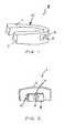
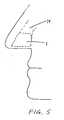
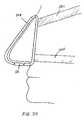
- FIG. 1The respiratory devices illustrated in Figs. 1-3 , 5 , 22 and 24 are not in accordance with the invention claimed, but they represent technical background that may be useful for understanding the nasal respiratory device of the present invention.
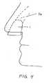
- the respiratory devices illustrated in Figs. 4 , 6 , 23 and 27may become in accordance with the invention claimed when at least some of the holdfast outside of the nasal cavity includes adhesive to secure the device in place.
- FIG. 1is a perspective view of a respiratory device adapted for an oral cavity.
- FIG. 2is a perspective view of another respiratory device adapted for the oral cavity.
- FIG. 3is a perspective view of the device shown in FIG. 2 , where the device is positioned in a patient's oral cavity.
- FIG. 4shows a respiratory device adapted for the nasal cavity.
- FIG. 5shows a respiratory device adapted to fit substantially within the nasal cavity.
- FIG. 6shows a cross-sectional view of the device shown in FIG. 4 , where an airflow resistor is shown within the device.
- FIGS. 7a and 7bshow cross-sectional views of the device shown in FIG. 4 ;
- FIG. 7ashows the device during inhalation, and
- FIG. 7bshows the device during exhalation.
- FIGS. 8a and 8bare perspective views of a respiratory device showing an airflow resistor during exhalation ( FIG. 8a ) and inhalation ( FIG. 8b ), respectively.
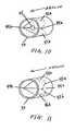
- FIGS. 9a and 9bare perspective views of a respiratory device having an airflow resistor where the airflow resistor is shown during exhalation ( FIG. 9a ) and inhalation ( FIG. 9b ), respectively.
- FIG. 10is a perspective view of a respiratory device having an airflow resistor where the airflow resistor is shown during exhalation.
- FIG. 11is a perspective view of a respiratory device having an airflow resistor where the airflow resistor is shown during exhalation.
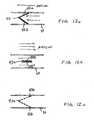
- FIGS. 12a and 12bshow cross-sectional views of the respiratory devices shown in FIGS. 9a, 9b , 10, and 11 during exhalation ( FIG. 12a ) and inhalation ( FIG. 12b ), respectively.
- FIG. 12cshows a cross-sectional view of a variation of the respiratory device during exhalation.
- FIGS. 13a and 13bare perspective views of a respiratory device having an airflow resistor where the airflow resistor is shown during exhalation ( FIG 13a ) and inhalation ( FIG. 13b ), respectively.
- FIG. 14is a perspective view of a respiratory device having an airflow resistor where the airflow resistor is shown during exhalation.
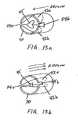
- FIGS. 15a, 15b, and 15care perspective views of a respiratory device having an airflow resistor.
- FIG. 15ashows the airflow resistor during higher levels of exhalation airflow and/or pressure.
- FIG. 15bshows the airflow resistor during lower levels of exhalation airflow and/or pressure.
- FIG. 15cshows the airflow resistor during inhalation.
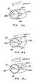
- FIGS. 16a and 16bare perspective views of a respiratory device having an airflow resistor where the airflow resistor is shown during exhalation ( FIG. 16a ) and inhalation ( FIG. 16b ), respectively
- FIGS. 17a and 17bare perspective views of a respiratory device having an airflow resistor where the airflow resistor is shown during exhalation ( FIG. 17a ) and inhalation ( FIG. 17b ), respectively.
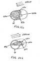
- FIGS. 18a and 18bshow cross-sectional views of a respiratory device having an airflow resistor where the airflow resistor is shown during inhalation ( FIG. 18a ) and exhalation ( FIG. 18b ), respectively.
- FIGS. 19a and 19bare cross-sectional views of a respiratory device having an airflow resistor where the airflow resistor is shown during low pressure and/or low airflow exhalation ( FIG. 19a ), and then during high pressure and/or high airflow exhalation ( FIG. 19b ).
- FIG. 20is a perspective view of a respiratory device where the device is removable and adapted for the nasal cavity.
- FIG. 21is a perspective view of a respiratory device where the device is removable and adapted for the nasal cavity.
- FIG. 22is a cross-sectional view of a respiratory device where the device is removable and adapted for the nasal cavity.
- FIG. 23is a cross-sectional view of a respiratory device where the device is removable and adapted for the nasal cavity.
- FIG. 24is a cross-sectional view of a respiratory device where the device is removable and adapted for the nasal cavity.
- FIG. 25is a cross-sectional view of a respiratory device where the device is removable and adapted for the nasal cavity.
- FIGS. 26a and 26bare perspective views of a respiratory device having a moveable air filter where the moveable air filter is shown during inhalation ( FIG. 26a ) and exhalation ( FIG. 26b ), respectively.
- FIG. 27is a perspective view of another respiratory device where the device is removable and adapted for the nasal cavity.
- FIG. 28shows a cross-sectional view of another respiratory device where the device is removable and adapted for the nasal cavity.
- Described hereare respiratory devices, kits, and methods for their use in improving respiratory and cardiovascular function.
- the respiratory devicesare referred to as respiratory devices or simply as "devices.”
- the devices and methods described hereinmay be useful to treat a variety of medical disease states, and may also be useful for non-therapeutic purposes.
- the devices and methods described hereinare not limited to the particular embodiments described. Variations of the particular embodiments may be made and still fall within the scope of the appended claims. It is also to be understood that the examples and particular embodiments described are not intended to be limiting. Instead, the scope of the present invention will be established by the appended claims.
- the respiratory devices described hereinalter airflow into and out of the lungs through a respiratory cavity such as the mouth and/or the nostrils of the nose.
- the respiratory devicestypically include an airflow resistor capable of at least partly obstructing airflow, particularly airflow in one direction (e.g., expiration) more than the opposite direction (e.g., inhalation).
- the respiratory devicesmay be used to increase the resistance to expiration during the expiratory phase of the respiratory cycle.
- Many of the respiratory devices described hereinmay prevent collapse of airways and airflow conduits, provide a method of drug delivery, and filter air of undesirable compounds or agents.
- the respiratory devices described hereingenerally comprise an airflow passageway and an airflow resistor.
- the airflow passageway(or “passageway”) generally defines a channel allowing the passage of air.
- the passagewaymay be of any suitable size or shape; however it is configured so that when the respiratory device is worn by a patient, the passageway comprises an opening leading toward the patient's lungs in fluid connection with an opening that leads away from the patient's lungs.
- the term "patient"is used to describe any user of the respiratory device, including users who are not using the respiratory device for therapeutic purposes.
- the airflow passagewaymay be any suitable length.
- the passagewaymay be as short as the airflow resistor will allow (e.g., extending only enough to support the airflow resistor).
- the airflow passagewaymay be longer than the space required to support the airflow resistor.
- the airflow passageway waymay be approximately as long as the length of an average nares. In some versions, the passageway extends the length of an average nasal chamber.
- the neutral diameter of the passagewaymay be of any appropriate size.
- Neutral diameterrefers to the diameter of the passageway when the device allows air to flow through the passageway without additional resistance (e.g., due to an airflow resistor).
- the diameter of the passagewaymay depend upon configuration of the respiratory device.
- respiratory devices configured to be inserted within the nasal cavitye.g., a nasal chamber
- Respiratory devices configured to be secured over an oral cavity or a nasal cavitymay have passageways of larger diameters.
- the diameter of a passagewaymay vary across the length of the device.
- the airflow passagewaymay comprise a dedicated structure defining the inner wall of the airflow passageway, or it may be a structural component of the device.
- the passagewaymay comprise a passage wall defined by a rim.
- a rimmay be a tube (or tunnel) of material of any appropriate thickness.
- the rimmay also be a frame, rather than a complete tube.
- the rimmay comprise a sufficiently rigid material so that it can support the passageway, and prevent the passageway from collapsing during use and during respiration.
- the rimcomprises a compressible material that may be compressed to facilitate insertion and removal, while maintaining the ability to support the passageway and prevent complete collapse of the passageway during respiration.
- the rimmay also be somewhat compressible during respiratory flow.
- the airflow passageway(including a rim portion) may also serve as an attachment site for other components such as airflow resistors, filters, anchors, etc.
- the rimmay be any suitable shape or size.
- the rimmay comprise a ring shape or an oval shape.
- the rimmay have an inner diameter which is equivalent to (or larger than) the diameter of the passageway.
- the rimcomprises a material having strength sufficient to prevent the collapse of a respiratory device that has been inserted into a nasal cavity.
- the rimmay comprise a metal, a polymer (particularly stiff polymers), etc.
- the rimmay comprise softer or "weaker" materials which are formed or arranged so that the final shape of the rim has sufficient strength to prevent the collapse of the respiratory device during use.
- the airflow passagewaydoes not include a dedicated structure such as a rim.
- the airflow passageway of the respiratory devicemay be a passageway through another component of the device, such as holdfast.
- the airflow passagewayis defined by a passageway through a holdfast.
- An airflow resistoris typically positioned in communication with at least one airflow passageway, so that at least some of the air flowing through the passageway passes the airflow resistor.
- an airflow resistormodulates, alters, varies, or keeps constant the amount of resistance, the degree of airflow, or the pressure differential across the device or through a passageway in the device.
- the airflow resistorinhibits airflow more greatly in one direction than the opposite direction.
- the airflow resistorregulates airflow to and from the lungs.
- the airflow resistorhas a greater resistance to exhalation than to inhalation during use.
- the airflow resistorcomprises a valve that does not appreciably impede airflow in a certain direction (e.g., inspiration), and that partially or completely impedes airflow in the other direction (e.g., expiration).
- the valveallows for an expiratory obstruction to be relieved if a certain degree of airflow or pressure differential across the device is achieved, as might be the case with coughing or nose blowing.
- the valvecomprises a flap made of a shape memory or deformable material (e.g., an elastic material); when the pressure differential across the valve (the expiratory airflow pressure) is large enough, the flap bends upon itself, thereby relieving the obstruction. This may be important during coughing and may also facilitate the clearance of mucous and other substances during coughing. After the cough, the flap returns to its original, non-bent conformation.
- any airflow resistance device capable of altering the resistance of air (e.g., due to inspiration and/or expiration) passing through an air passagewaymay be used it increases the resistance of air flow in the exhalation direction more than in the opposite, inhalation direction.
- Valve-type airflow resistorsare particularly suitable. Examples of valves which may be used as airflow resistors include: flap valves (having one or more flaps); hingeless valves; stopper-type valves; membrane-type valves; ball valves; balloon-type valves; and the like. This list is not intended to be exhaustive, and other types of selective airflow resistors may be used. Moreover, multiple airflow resistors may also be used, which may include combinations of different types of airflow resistors.
- the respiratory devicefurther comprises a holdfast which may releasably secure the device in communication with a nasal cavity.
- the holdfastmay facilitate the positioning and securing of the device in a desired location, such as over or within (e.g., substantially within) a respiratory orifice.
- the holdfastmay allow the device to be anchored, positioned, and/or stabilized in any location that is subject to respiratory airflow such as a respiratory cavity.
- nasal cavitiesexamples include nasal and oral cavities.
- Nasal cavitiesmay comprise the nostrils nares or nasal chambers, limen, vestibule, greater alar cartilage, alar fibrofatty tissue, lateral nasal cartilage, agger nasi, floor of the nasal cavity, turbinates, sinuses (frontal, ethmoid, sphenoid, and maxillary), and nasal septum.
- the term "nasal cavity”may refer to any sub-region of the Nasal Fossa (e.g., a single nostril, nare, or nasal chamber).
- An oral cavityincludes the cavity of the mouth (e.g., vestibule and mouth cavity proper), and any sub-region thereof, including or more than one of the following structures: maxilla, mandible, gums, lips, teeth, jaw, tongue, hard or soft palate and the recess or gap between the teeth/gums and the lips.
- the holdfastalso secures a seal between the respiratory device and the respiratory airway, so that at least some of the air exchanged between the outside of the patient and the respiratory airway must pass through the respiratory device.
- the holdfastseals the device in communication with a respiratory cavity completely, so that all air must be exchanged through the device.
- the holdfast sealis incomplete, so that only some of the air exchanged between the patient and the external environment passes through the device.
- airmay be air from environment external to the patient, or it may be any respiratory gas (e.g., pure or mixed oxygen, CO 2 , heliox, or other gas mixtures provided to the user).
- the holdfastmay comprise an anchor or anchor region.
- the deviceis to be placed by the patient or the healthcare provider in or around the nasal cavity.
- Holdfasts appropriate for nasal cavitiesmay secure the device in position partially within a nasal cavity (e.g., through one or both nostrils) or against surrounding structures.
- the holdfastmay comprise a shape, surface or material that secures the device in communication with a nasal cavity.
- the outer surface of the devicemay comprise a holdfast including an adhesive material.
- the holdfastalso partially or completely seals the device in communication with the nasal cavity.
- the holdfastmay comprise non-insertive mechanisms.
- the holdfastcomprises a mechanical connection between the device and the user, such as a clips, straps, and the like.
- the holdfastis formed from a soft or compliant material that provides a seal and enhances patient comfort. Furthermore, compliant materials may reduce the likelihood that the device cuts off blood flow to the part of the respiratory cavity and surrounding regions (nose) to which the device is anchored.
- This compliant materialmay be one of a variety of materials including, but not limited to, plastic, polymers, cloth, foamed, spongy, or shape memory materials Shape materials include any that have a preferred conformation, and after being deformed or otherwise deflected or altered in shape, have tendency to return to a preferred conformation. Soft shape memory materials may include, but are not limited to, urethane, polyurethane, sponge, and others (including “foamed”' versions of these materials).
- the devicemay project out of the nostril, depending on the particular embodiment.
- the devicemay be located completely outside of the nose, for example, in some versions the holdfast has a shape that conforms to the outside surface of the nose.
- the holdfastmay comprise one or more straps, bands, or the like to ensure an adequate fit and/or seal maintaining the device in communication with the nasal cavity.
- a devicemay be placed at least partly in both nostrils, and may comprise a bifurcated passageway or two passageways that the holdfast places in communication with the nasal cavity through each nostril.
- the inspiratory and/or expiratory airflow to arid from the lungsmay be regulated through each nostril separately or together.
- separate devicesmay be placed at least partly in each nostril, and may be connected to each other and/or the patient using a clip, tether, strap, band, chain, string, or the like.
- a clip, tether, strap, band, chain, string, or the likeSuch a system would facilitate subsequent removal of the device and make migration of the devices deeper into the nasal cavity less likely.
- an adhesive flapmay be present to help attach the device to the inside or outside of the nose (including the nostrils), to the oral cavity, to the neck, or to the face.
- Respiratory devicesmay be made from any appropriate material or materials
- the devicesinclude a shape memory element or elements, as part of the holdfast, in the airflow resistor, or in giving form to the passageway.
- Any convenient shape memory materialthat provides for flexibility and resumption of configuration following removal of applied force may be employed in these embodiments.
- shape memory alloysmay be used.
- a variety of shape memory alloysare known, including those described in U.S. Pat. Nos.: 5,876,434 ; 5,797,920 ; 5,782,896 ; 5,763,979 ; 5,562,641 ; 5,459,544 ; 5,415,660 ; 5,092,781 ; 4,984,581 .
- the shape memory alloy that is employedshould generally be a biocompatible alloy.
- Biocompatible alloysmay include nickel-titanium (NiTi) shape memory alloys sold under the NitinolTM name by Memry Corporation (Brookfield, Conn.).
- NiTinickel-titanium
- spring steel and shape memory polymeric or plastic materialssuch as polypropylene, polyethylene, etc.
- Rubber and polymeric materialsmay also be used, particularly for the holdfast or airflow resistor.
- materials which may be usedinclude: latex, polyethylene, polypropylene, polystyrene, polyvinyl chloride, polyvinylidene chloride, polyvinyl acetate, polyacrylate, styrene-butadiene copolymer, chlorinated polyethylene, polyvinylidene fluoride, ethylene-vinyl acetate copolymer, ethylene-vinyl acetate-vinyl chloride-acrylate copolymer, ethylene-vinyl acetate-acrylate copolymer, ethylene-vinyl acetate-vinyl chloride copolymer, nylon, acrylonitrile-butadiene copolymer, polyacrylonitrile, polyvinyl chloride, polychloroprene, polybutadiene, thermoplastic polyimide, polyacetal, polyphenylene sulfide, polycarbonate, thermoplastic polyure
- Biocompatible materialsmay be used, particularly for those portions of the device (e.g., the holdfast) which may contact a user.
- the biocompatible materialsmay also include a biocompatible polymer and/or elastomer.
- Suitable biocompatible polymersmay include materials such as: a homopolymer and copolymers of vinyl acetate (such as ethylene vinyl acetate copolymer and polyvinylchloride copolymers), a homopolymer and copolymers of acrylates (such as polypropylene, polymethylmethacrylate, polyethylmethacrylate, polymethacrylate, ethylene glycol dimethacrylate, ethylene dimethacrylate and hydroxymethyl methacrylate, and the like), polyvinylpyrrolidone, 2-pyrrolidone, polyacrylonitrile butadiene, polyamides, fluoropolymers (such as polytetrafluoroethylene and polyvinyl fluoride), a homopoly
- Other materials of interestinclude any materials that can serve as filters for allergens, pollen, dander, smog, etc. By providing a filter within the device, sinusitis, sleep apnea, snoring, hay fever, allergic rhinitis, and other allergic respiratory conditions may be reduced or prevented.
- This filtermay in fact be part of the airflow resistor or may be a separate component of the device.
- Any suitable filtering material known to those skilled in the artmay be used with the respiratory devices described herein. Such materials include, but are not limited to, activated carbon charcoal filters, hollow-fiber filters, and the like.
- the respiratory devicemay comprise a filter that remains in the path of inhalation and/or exhalation during use.
- the filter materialremains in the path of both inspiratory and expiratory airflow. This filter material may not appreciably alter resistance to airflow in either direction, or it may alter airflow to substantially the same degree in both directions (inhalation and exhalation).
- the filtercomprises a material having a large pore size so that airflow is not significantly inhibited.
- the airflow resistormay be oriented in any direction.
- the airflow resistorcomprises valve flaps that are oriented such that both flaps are in a closed position during inspiration and in an open position during expiration.
- the respiratory devicesare orientated so that the airflow resistor increases resistance to expiration, and has a relatively lower or negligible resistance to inspiration.
- the respiratory deviceis reversible, so that it may be used in alternative, opposite orientations by the user (e.g., to increase the resistance of inspiration relative to expiration in one orientation, or to increase the resistance of expiration relative to inspiration in another orientation).
- the respiratory deviceis shaped so that the direction of the airflow resistor is immediately evident
- the respiratory devicemay be of a different shape or size on one end, or may include a visual indication.
- the respiratory devicemay be shaped so that it fits securely into a respiratory orifice only in one orientation (e.g., so that the airflow resistor inhibits the expiration more than it inhibits inhalation).
- a flange or other mechanical stopmay be used to insure proper orientation, while simultaneously preventing migration of the device further into the respiratory orifice.
- the deviceprovides some level of resistance to expiration. It may be preferable to have little if any effect on resistance to inspiration, though in some cases, some degree of inspiratory restriction may be beneficial. In some versions of the device, both inspiration and expiration may be inhibited by the airflow resistor.
- the devicemay also be adapted for comfort. Any device placed either in or around the nose should not be painful, and if possible not very noticeable by the patient.
- the holdfastmay be shaped to conform to the attachment site in or around the respiratory orifice.
- the holdfastcomprises a flexible or shapeable material (e.g., a foam or other soft shape-memory material).
- the entire respiratory devicecomprises a soft material.
- the devicemay be adapted so that it is more or less visible to others.
- the devicemay be configured to be placed high enough within the nostrils to make it difficult for others to see.
- the devicemay be of any color and/or pattern that help to camouflage it.
- itmay be useful to include colors and patterns that stand out, including ones that are fluorescent or otherwise offer increased visibility during the night or other setting where ambient light is reduced.
- the respiratory devicemay be "one size fits all", so that it may be used with any patient (or any patient of approximately the same size), despite differences in shapes and sizes of their nose/nostrils, oral cavity, teeth and other relevant anatomic features.
- the devicesmay conform to a range of sizes, for example “small,” “medium,” and “large” (or any other appropriate range, such as, e.g., a numerical range).
- the devicesmay involve a custom fit of the device or devices to the patient.
- Custom fittingmay improve patient comfort and potentially improve performance by improving the seal between the device and the patient's nasal cavity and nostrils, for example.
- custom fittingmay involve the placement of a device in warm or cold liquid or air with subsequent placement in the patient's nose. This process is meant to "prime" the materials in the device (e.g., particularly the materials of the holdfast), so that when holdfast is secured to the patient, the device permanently assumes a shape or configuration corresponding to a portion of the patients anatomy.
- an airflow resistormay fit within a larger structure (such as the passageway) so that some airflow through or around the airflow resistor is always allowed.
- a constant opening between the airflow resistor and the anchorthat secures the airflow filter in communication with the passageway. This may ensure that expiratory and/or inspiratory airflow is never completely occluded.
- the airflow resistorcomprises a "hole" or opening.
- a flap valvemay comprise an opening through the flap valve permitting airflow through the flap valve even when the valve is closed.
- the devicemay also create a PEEP effect by differentially changing the resistance to airflow in one direction based on the pressure applied against the device. For example, in some designs, expiratory airflow is subjected to resistance by the airflow resistor (or valve) until a certain threshold pressure differential or level of airflow is achieved; below that threshold, a more complete closure of the airflow resistor occurs (potentially completely occluding airflow through the device).
- the desired levels of PEEPare on the order of about 0.1 to about 30 cm H 2 O and more preferably about 1 to about 15 cm H 2 O pressure.
- the differential resistancemay also be triggered in the opposite direction; for example, above a certain threshold of pressure or level of airflow, the airflow resistor (e.g., valve) may open to decrease the resistance due to the airflow resistor, as when a patient coughs, sneezes, or blows his or her nose.
- the airflow resistore.g., valve
- the optimal level of expiratory resistance or PEEP provided by the devicemay vary from patient to patient. In some versions, adequate expiratory resistance or PEEP is created to offer the desired benefits, but not providing too much expiratory resistance or PEEP so that the patient preferentially begins breathing through the mouth. In some cases, the user may test the device or devices while being monitored by a healthcare provider, a camera, a polysomnograph, or any other device that will help to assess the optimal level of resistance or therapy provided by the subject devices.
- I:E ratioinspiratory time:expiratory time ratio
- the use of an airflow resistormay also alter the inspiratory time:expiratory time ratio (I:E ratio), which is defined as the ratio of inspiratory time to expiratory time.
- I:E ratiowill be between about 3:1 and about 1:10 and more preferably about 1:1.5 to about 1:4 depending on the needs of the individual patient. In some versions, the desired ratio is approximately about 1:3.
- the devicecomprises an insertion, adjustment, or removal mechanism.
- this mechanisminvolves any appropriate rigid or non-rigid positioner that facilitates removal or positioning of the device.
- Non-rigid positionersinclude but are not limited to cables, chains, wires, strings, chains, sutures, or the like.
- Rigid positionersinclude knobs, handles, projections, tabs, or the like. A user may grasp or otherwise manipulate the positioner to facilitate insertion, re-adjustment, or removal of the device.
- various applicators or other insertion devicesmay be used. For example, a tubular applicator holding a repiratory device adapted for insertion into a nasal cavity may be advanced into the nasal respiratory orifice (e.g., nostril) to insert the respiratory device.
- the devicemay be oversized. Oversizing the device may reduce resistance in one or more direction of airflow.
- the passageway through the deviceis oversized.
- an outer portion of the device that contacts the respiratory orificeis oversized.
- the respiratory devicemay exert pressure against the nasal cavity of a user. In patients with obstructive sleep apnea or snoring, for example, increasing the size of the a respiratory device configured to be inserted into one or more nostrils may prevent the more distal tissues of the airway, tongue, and nasopharynx from being sucked in or closed during inspiration.
- airflow through an oversized passagewaymay assume a less turbulent flow profile, resulting in a decreased propensity for noise production in the case of snoring, for example.
- the respiratory device passagewaymay be shaped so as to decrease turbulence of airflow.
- the shape and activity of the airflow resistormay be chosen to minimize turbulence and, therefore, sound or vibration.
- the deviceis used with an active agent.
- the active agentcomprises a drug.
- An active agente.g., a medicament
- An active agentcan be placed in or on the device to deliver the active agent into the mouth, tongue, hard and soft palates, sinuses, nose, pharynx, vocal cords, larynx, airways, lungs, trachea, bronchi, bronchioles, alveoli, air sacs, or any tissues that are exposed to inspiratory or expiratory airflow.
- the active agentmay be embedded or impregnated in the device or components of the device.
- the active agentis a coating.
- An active agentmay comprise any compound that is in some way useful or desirable for the patient.
- the active agentmay be any odorant, including: menthol, phenol, eucalyptus, or any agent that provides a fragrance in the inspired air.
- an active agentmay comprise a drug with beneficial effects, such as beneficial vasculature effects.
- an active agentmay comprise a drug that effects the blood vessels (oxymetazoline or any other vasoactive compound), nasopharynx, airways or lungs (albuterol, steroids, or other bronchoconstriction or bronchodilation compounds).
- An active agentmay comprise an antibiotic or a steroid for example. The above list of active agents is not meant to be limiting.
- An active agentmay be placed in or on any portion of the device. Furthermore, the location of the active agent within the respiratory device may specifically guide the delivery of the active agent. For example, in versions of the respiratory device configured to be placed inside a respiratory cavity, when the holdfast comprises an active agent (e.g., coated, embedded or otherwise part of the holdfast), the drug may be delivered through the mucus membranes of the respiratory cavity. In another example, an active agent may be included as a powder or releasable coating that may be aerosolized and delivered within the respiratory system. Thus, an active agent may be on a surface of the device (e.g., the passageway, holdfast or airflow resistor) or embedded within any surface of the device. A separate drug-containing region may also be included in the device. The addition of an active agent may be of particular interest in treating allergies and sinusitis. Respiratory devices (with or without airflow resistors) may therefore comprise active agents such as menthol or other fragrant compounds.
- active agentssuch as menthol or other fragrant compounds.
- the respiratory devicesmay be manufactured and assembled using any appropriate method.
- Representative manufacturing methods that may be employedinclude machining, extruding, stamping, and the like.
- Assembling methodsmay include press-fitting, gluing, welding, heat-forming, and the like.
- Fig. 1provides a perspective view of one version of the respiratory device 1 in which the device can fit into the oral cavity of a user.
- the holdfast 5comprises grooves 2 and 3 in which the user's teeth and/or gums may preferentially sit, thus securing the device in the oral cavity.
- Airflow resistor 4represents any airflow resistor capable of modulating inspiratory and/or expiratory resistance during any or all portions of the respiratory cycle, as described above.
- the airflow resistor 4sits within a passageway 6 .
- Fig. 2is a perspective view of a respiratory device 1 that may be fitted in an oral cavity.
- the patient's teeth and/or gumshelp to secure the device in place by contacting the holdfast.
- the holdfastcomprises an inner frame 10 , and outer frame 12 , and a positioner 14 .
- the inner frame 10is located on the internal portions of the patient's teeth or gums.
- the outer frame 12is positioned outside the patient's teeth/gums or outside the patient's lips.
- the positioner 14is located between the upper and lower jaws teeth, and/or gums.
- An airflow resistor 4modulates inspiratory and/or expiratory resistance during any or all portions of the respiratory cycle.
- Fig. 3is a view of the device 1 shown in Fig. 2 , where the device is depicted within and protruding from the patient's oral cavity.
- the outer frame 12 of the holdfastis shown outside of the patient's teeth and gums.
- the airflow modulator 4 within the passageway 6modulates inspiratory and/or expiratory resistance during any or all portions of the respiratory cycle through the oral respiratory passageway.
- One or more airflow resistors 4 and/or passageways 6may be used in this (or any, e.g., oral or nasal) respiratory device.
- Fig. 4is a perspective view of a respiratory device 1 in which the device is removable and may be secured within a patient's nasal cavity 16 .
- the deviceprotrudes from the nasal opening.
- the sides of the devicecomprise a holdfast which is shown fitting snugly within the nasal passage, as well as projecting out from the nasal passage.
- Fig. 5is a perspective view of another version of the respiratory device 1 in which the device is placed completely within the nasal passage 16 . The entire respiratory device fits snugly within the nasal passage.
- Fig. 6is a cross-sectional view of a respiratory device 1 similar to those shown in Figs. 4 and 5 .
- a holdfast 28comprises the outer surface of the device that contacts the inner portions of the nasal cavity, thus serving to secure the device in place while creating a partial or complete seal.
- the passageway 6 through which air may flowis surrounded by a rim 30 that provides additional structural support to the device.
- a rim 30is not required, particularly if the walls of the passageway (which may be defined by the holdfast 28, for example) provide sufficient support.
- An airflow resistor 24is included within the passageway which modifies expiratory resistance.
- Figs. 7a and 7bshow more detailed views of the operation of airflow resistors shown in Figs. 4 and 5 .
- These cross-sectional viewsillustrate the holdfast 28, the optional rim 30, the passageway 6, and the airflow resistor, shown as a valve 32.
- the rim 30separates the holdfast 28 and the valve 32, frames the valve 32, and provides overall structural support to the entire device.
- the valve 32is shown in the open position, providing less resistance to airflow.
- Fig. 7bvalve 32 is shown in the closed position, providing more resistance to airflow, because the cross-sectional area of the passageway 6 has been constricted by the closing of the valve.
- Figs. 8a and 8bshow perspective views of an airflow resistor that could be used, for example with any of the devices described in Figs. 1-5 .
- a rim 30is shown.
- the rimmay be part of the holdfast which positions and secures the device within a respiratory passageway; alternatively, additional material (e.g., compliant material) may be attached to the rim to form the holdfast.
- additional materiale.g., compliant material
- the rimprovides support to the airflow resistor 24.
- the airflow resistoris shown here as a flap valve mechanism that comprises a flap 36 that pivots around a joint 38 and is connected to a fixed element 40.
- Fixed element 40is attached to the inner region of the passageway 6, which is defined in this figure by the rim 30.
- the flap valve and the inner surface of the passageway 6may constitute a single piece.
- the flap 36, joint 38, and fixed element 40may be fabricated as a single piece, in which case joint 38 may be a hinge.
- joint 38may be a pinned hinge or a non-pinned hinge joint.
- rim 30, flap 36, joint 38, and fixed element 40may all be created as a single piece or material.
- flap 36is able to pivot in relation to fixed element 40 depending on the direction of the patient's airflow and the desired level of resistance to airflow. Fig.
- FIG. 8ashows the airflow resistor with flap 36 in a closed position during expiration, thus providing increased resistance.
- the flap portion of the airflow resistorcloses completely, as shown.
- the edges of the flap 36may close off the entire passageway (as shown), or may only occlude a portion of the passageway.
- Fig. 8bshows the airflow resistor with flap 36 in the open position (e.g., during inspiration), thus providing decreased resistance.
- Flap 36may define a hole, or may have other openings (which may stay open during all or part of the respiratory cycle) to help modulate the degree of inspiratory and expiratory resistance. The flap 36 may return to a preferred opened or closed position.
- a shape memory materialsuch as a torsion spring
- the holdfastmay apply force to flap 36 to return it to a closed position.
- the use of foam or urethane surrounding the airflow resistormay provide such force as to close flap 36 in the absence of adequate airflow.
- Bi-leaflet versions of the airflow resistorare also contemplated and will have similar function. These bi-leaflet versions may involve multiple sets of flaps 36, joints 38, and fixed elements 40, etc.
- Figs. 9a and 9bshow a perspective view of another embodiment of an airflow resistor that could be used in any of the respiratory devices described herein.
- the inner surface of the passageway shownincludes a rim 30 that supports the airflow resistor.
- This airflow resistor 24is also shown as a valve mechanism.
- Moveable elements 42a and/or 42boverlaps are attached to one another or are constructed from a single piece.
- Moveable elements 42a and 42bare attached to the inner surface of the passageway (shown as a rim 30 ) at attachment points 44a and 44b, and these attachment points may allow the valve to pivot around a hinge 43 in response to direction and amplitude of airflow.
- attachment points 44a and 44bare formed directly into the rim 30 or holdfast 28 during the manufacturing (e.g., casting) process.
- the hingeis statically attached to an inner region of the passageway, and the flaps 42a and 42b are movably (or flexibly) attached to the hinge.
- Fig. 9ashows this airflow resistor when the resistance is high (e.g., the flap valve is mostly closed), as during expiration
- Fig. 9bshows the airflow resistor when the resistance is low (e.g., the flap valve is mostly open), as during inspiration.
- Fig. 10shows a perspective view of another embodiment of an airflow resistor that is similar in structure and function to the device shown in Figs. 9a and 9b .
- the airflow resistor shownhas an internal opening 45 that is located approximately where moveable elements 42a and 42b pivot relative to one another.
- the addition of internal opening 45modulates airflow (e.g., inspiratory or expiratory airflow) by altering the level of resistance. Addition of this opening reduces the resistance in one direction (e.g., expiratory resistance, when the flap valve is "closed") more than resistance in the opposite direction (e.g., inspiratory resistance, when the flap valve is "open”).
- Fig. 11shows a perspective view of another embodiment of an airflow resistor that is similar in structure and function to the device shown in Figs. 9a and 9b .
- Peripheral openings 46a and 46bare placed completely within, or on the periphery of the moveable elements 42a and 42b. These peripheral openings 46a and 46b also modulate inspiratory and/or expiratory resistance. The addition of peripheral openings 46a and 46b helps modulate inspiratory and expiratory airflow by altering the level of resistance. Addition of these peripheral openings also reduce the resistance in one direction (e.g., expiratory resistance, when the flap valve is "closed") more than resistance in the opposite direction (e.g., inspiratory resistance, when the flap valve is "open”).
- Figs. 12a and 12bshow more detailed views of the operation of the valve mechanisms as described in Figs. 9a, 9b , 10, and 11 .
- the airflow resistoris oriented so that the airflow resistor increases resistance during expiration relative to inhalation (e.g., the lungs are located to the right in Figs. 12a, 12b and 12c ).
- Moveable elements 42a and 42bare coupled to each other via hinge 43.
- Fig. 12ademonstrates the valve mechanism during expiration, in which moveable elements 42a and 42b are in a closed position due to the expiratory airflow in the direction from the lungs to the external environment.
- Fig. 12ademonstrates the valve mechanism during expiration, in which moveable elements 42a and 42b are in a closed position due to the expiratory airflow in the direction from the lungs to the external environment.
- FIG. 12bdemonstrates the valve mechanism during inspiration, in which moveable elements 42a and 42b are in an open position due to the inspiratory airflow in the direction from the external environment to the lungs.
- Fig. 12cdemonstrates a modification of the valve mechanism shown in Figs. 12a and 12b in which there are one or more apertures within or on the periphery of the moveable elements that reduce resistance to expiratory airflow, further increasing the rate of expiratory airflow. All of these valve mechanisms and configurations can be placed in the opposite orientation so that inspiratory airflow leads to valve closure and expiration leads to valve opening.
- Moveable elements (flaps) 42a and 42b of the airflow resistormay be made of any appropriate material.
- materials which have sufficient stiffness to withstand the forces applied by the respiratory processmay also be desirable.
- durable materialse.g., which may withstand the moisture, etc. of the respiratory passage
- the devicesare disposable, and thus durability may be less critical.
- the moveable elements 42a and 42bmay also be made from porous materials or filters, etc. that do not overly restrict or resist airflow but at the same time can remove debris, pollen, allergens, and infectious agents for example.
- Figs. 13a and 13bshow perspective views of another airflow resistor that could be used in any of the devices described herein.
- Fig. 13ashows the airflow resistor (a flap valve) in a closed position, as might be seen during expiration, resulting in increased resistance to airflow.
- Fig. 13bshows the airflow resistor in an open position, as might be seen during inspiration, resulting in a decreased resistance to airflow relative to the closed position. Because of the small profile of the retracted flap valves, the resistance added by the airflow resistor when the airflow resistor is "open" may be negligible.
- Moveable elements 42a and 42bare attached to each other or are a single piece.
- Moveable elements 42a and 42bare attached to the walls of the passageway (in this example, defined by a rim 30 ), to the rim 30, or to the holdfast 28 by a securing element 54a and 54b which uses a tab, adhesives, press fit, external pressure (as from a holdfast 28 ) or any way known to those skilled in the art.
- Internal opening 45is located centrally, decreasing the resistance to expiratory airflow (in the "closed" state), although peripheral locations are also contemplated.
- the size and number of openings in the valvesmay determine the resistance of the airflow resistor. Thus, the size and number of openings may be selected in order to determine the I:E ratio.
- Fig. 14provides a perspective view of another embodiment of an airflow resistor that is similar in structure and function to the airflow resistor shown in Figs. 13a and b.
- the movable elementsfurther comprise a reinforcement support 60a and 60b that is located partially or completely covering the moveable elements 42a and 42b.
- the reinforcement supportprovides additional structure and/or support to these moveable elements.
- reinforcement support 60a and 60bmay also promote a more reliable seal and may standardize the movements of moveable elements 42a and 42b while reducing the likelihood that moveable elements will invert, buckle in the direction of airflow, or otherwise fail, especially when exposed to high pressures and airflow as might be seen during coughing.
- reinforcement support 60a and 60balso dampens any whistling or other sounds during inspiration or expiration.
- Moveable element 42a and reinforcement support 60a and moveable element 42b and reinforcement support 60bmay be a single unit (or each "flap" may be a single unit).
- both moveable elements 42a and 42b and both reinforcement support 60a and 60bmay be a single unit.
- a central opening 45is also shown in the figure.
- Figs. 15a-15cshow perspective views of another embodiment of an airflow resistor that may be used in any of the devices described herein.
- the airflow resistoris similar to that shown in Figs. 13a and 13b with the exception that internal opening 45 is replaced by another airflow resistor 64 (a "nested airflow resistor").
- This nested airflow resistor 64automatically closes when the flow through the valve (or the pressure differential across the valve) falls below a predetermined level. This allows the airflow resistor (with the nested airflow resistor region) to provide positive end expiratory pressure (PEEP).
- PEEPpositive end expiratory pressure
- Fig. 15athe airflow resistor is shown during exhalation, and the moveable elements 42a and 42b of the airflow resistor are in the closed position.
- the nested portion of the airflow resistor 64is open so long as the pressure differential across the airflow resistor and/or airflow is above a certain level.
- this figuredemonstrates the beginning of expiration, when airflow in the passageway and pressure differential are largest.
- FIG. 15bthe same airflow resistor is again shown during expiration, and moveable elements 42a and 42b of the airflow resistor are still in the closed position.
- the nested airflow resistor region 64now assumes a closed position, since the pressure differential across the airflow resistor and airflow through the passageway is no longer above the threshold value.
- This scenariomay correspond to the later stages of exhalation, when airflow and pressure differential are decreasing or are lower.
- PEEPhas been created.
- the nested airflow resistor 64may be set to close whenever air pressure in the respiratory orifice coming from the lungs is less than 5.0 cm H 2 0.
- FIG. 15cshows the device during inhalation, in which moveable elements 42a and 42b of the airflow resistor are in the open positions, allowing inhalatory airflow with minimal resistance to said airflow.
- Figs. 16a and 16bshow perspective views of another embodiment of an airflow resistor that may be used in any of the devices described herein.
- Fig 16ashows a hingeless valve 76 in a closed position during exhalation, in which there is increased resistance to airflow.
- FIG. 16bshows a hingeless valve 76 in an open position during inspiration, in which there is decreased resistance to airflow.
- the hingeless valve 76may also comprise one or more holes within its structure to allow airflow in either direction at various stages of the respiratory cycle. For example, despite being in a closed position, the hingeless valve 76 would still allow some level of expiratory airflow. Alternatively, the hingeless valve 76 might never close completely. Even in a closed state, its flaps may never completely block all airflow.
- Figs. 17a and 17bshow perspective views of another embodiment of an airflow resistor that could be used in any of the devices described herein.
- the membrane-type airflow resistor shown in Figs. 17a and 17bcomprises a membrane 80 (that may or may not be floppy) that is attached by a connector 82 to the body of the airflow resistor.
- the membrane 80seats itself against a rim 30 and/or an apposition support 84 which may project from the sides of the passageway (e.g., from the rim 30 ) to support the membrane 80 during exhalation.
- Membrane 80may have an opening 86 (or openings) which remain open during both inspiration and exhalation. In some versions of the airflow resistor, membrane 80 does not have an opening. In still other versions, there are several openings within membrane 80.
- Figs. 18a and 18bshow cross-sectional views of another embodiment of an airflow resistor that could be used in any of the devices described herein.
- Fig. 18ashows the airflow resistor during inspiration, during which deformable member 90 is unfurled leading to decreased resistance and increased airflow.
- Fig. 18bshows the airflow resistor during expiration, during which deformable member 90 assumes an orientation or folding configuration that leads to increased resistance and decreased airflow.
- Deformable member 90may have a preferred default position (a tendency to default to a preferred orientation in the absence of external influences or pressures) that may allow such an airflow resistor to offer a PEEP effect.
- Figs. 19a and 19bshow cross-sectional views of another embodiment of an airflow resistor that could be used in any of the devices described herein. This is a stopper-type airflow resistor.
- Fig. 19ashows the airflow resistor on exhalation with little to no airflow and minimal pressure differential across the valve.
- Fig. 19bshows the device during more robust exhalation, characterized by increased airflow and increased pressure differential across the valve. Stopper 92 is connected to return mechanism 94.
- Stopper 92may also have an opening within it to allow airflow at all times or at specific parts of the respiratory cycle (e.g., another, nested, airflow resistor, such as one allowing airflow during inhalation, but not exhalation), thereby providing fluid communication between the airways and the external environment.
- stopper 92may have a valve portion that is open during inhalation and closed during exhalation, or vice versa.
- the airflow from right to leftis insufficient to overcome the spring force provided by return mechanism 94, and stopper 92 seals against seating supports 96a and 96b.
- Fig. 19athe airflow from right to left is insufficient to overcome the spring force provided by return mechanism 94, and stopper 92 seals against seating supports 96a and 96b.
- FIGS. 19a and 19bthe airflow from right to left is sufficient to overcome the spring force provided by return mechanism 94, and stopper 92 is displaced leftward and thus expiratory airflow is allowed.
- the mechanism described in FIGS. 19a and 19bis one way in which PEEP can be created by the device.
- Fig. 20is a perspective view of another embodiment of the respiratory device where the device is removable and may be placed in communication with the nasal cavity.
- a holdfast 28is located between the patient's nose and the airflow resistor in the device 1, providing a partial or complete seal, anchoring the device, and providing comfort for the patient.
- the holdfast 28has a cross section that is roughly circular and capable of fitting within a patient's nostrils.
- Fig. 21is a perspective view of another embodiment of a respiratory device where the device is removable and may be placed within the nasal opening.
- This deviceshows a holdfast 28 having an approximately oval cross-section. Many such cross-sectional shapes are possible to optimize placement, anchoring, sealing, and comfort, including a variety of conical or asymmetric shapes designed to fit within a patient's nasal openings.
- the rim 30 and/or any airflow resistor 4may also assume any desired cross sectional shape, including that of an oval or any other non-circular orientation.
- the holdfast 28will be shapeable, deformable, or adjustable by the patient either before, after, or during placement of the device.
- the devicecan be customizable to fit individual patients through the use of imaging modalities including MRI, CT, xray, or direct vision, or through the use of molding techniques that are common in dentistry and other fields.
- Fig. 22is a cross-sectional view of a respiratory device where the device is removable and may be secured in fluid communication with a nasal cavity.
- the devicedoes not contain any moveable components that alter airflow.
- the devicecomprises a holdfast 28 and rim 30 that lends the device support.
- the devicemay be oversized to decrease resistance and increase airflow in one or more directions.
- a drug(with either an active or inactive ingredient) may be embedded in or located on any of the device's components, for example, the rim 30. It is appreciated that in some cases, there may be no rim 30, so long as structural support is provided by another component of the device, e.g., the holdfast. In this case, the drug may be loaded or coated on the holdfast or within the passageway.
- Fig. 23shows a cross-sectional view of another respiratory device where the device is removable and may be secured in communication with a nasal cavity.
- Each passagewayis shown with an airflow resistor 24 therein.
- the holdfast 28surrounds both passageways, and each passageway includes an (optional) rim 30.
- Each of the flow resistors 24may increase or decrease resistance to airflow independently and may work simultaneously or at different times during the respiratory cycle. For example, in some cases, during inhalation, one of the airflow resistors 24 may decrease resistance to airflow while the second airflow resistor 24 increases resistance to airflow. On exhalation, the first airflow resistor 24 may increase resistance to airflow while the second airflow resistor 24 decreases resistance to airflow. In other words, inspiratory airflow may proceed through one location, and expiratory airflow may proceed through a second location within the same device.
- Fig. 24is a cross-sectional view of another respiratory device where the device is removable and may be secured in communication with a nasal cavity.
- the deviceis shown with a fixed filter 98 that is located in the path of the airflow as it traverses the device.
- the fixed filter 98may help clear the airflow of any solid or liquid particles, debris, odors, allergens, pollen, and/or infectious agents.
- This filter 98may remain roughly fixed in place during all parts of the respiratory cycle though some degree of movement may be permitted.
- a drugmay be placed within or on the surface of one or more components of the device to provide additional benefit to the patient.
- the addition of fixed filter 98may not lead to increased resistance in either direction, unless such a design is desired.
- the fixed filter 98can be created from any number of filter materials that are known to those skilled in the art. This fixed filter 98 may be used in any of the respiratory devices herein, in addition to, or as an alternative to, an airflow resistor 4.
- Fig. 25is a cross-sectional view of another embodiment of the respiratory device, where the device is removable and may be secured in communication with a nasal cavity.
- the respiratory device of Fig. 25comprises a moveable cleansing filter 100 that is shown located within the device, and which may help to clear the airflow of solid or liquid particles, debris, odors, allergens, pollen, and/or infectious agents.
- the filtermay be configured to move so that it filters only during inhalation (or exhalation), or may move out of the way during periods of extremely large airflow (or air pressure) in the airflow passageway (e.g., during coughing, nose blowing, sneezing).
- Fig. 26a and 26bare perspective views of one version of a moveable cleansing filter where the moveable cleansing filter is shown during inhalation and exhalation respectively.
- a movable cleansing filtermay be a movable filter, scrubber, or any other device capable of removing (particularly selectively removing) any solid or liquid particles, debris, odors, allergens, pollen, and/or infectious agents.
- This moveable cleansing filtermay be used in any of the respiratory devices herein, in addition to, or as an alternative to, an airflow resistor 4.
- Fig. 26ashows the moveable cleansing filter (shown as movable filters) during inspiration (during which airflow travels from right to left in the figure) leading to displacement of moveable filter elements 102a and 102b away from one another.
- 26bshows the moveable cleansing filter during expiration (during which airflow travels from left to right in the figure) leading to displacement of moveable filter elements 102a and 102b towards one another.
- airflowpasses through the moveable filter elements 102a and 102b and the air may be cleansed of the relevant substances.
- airflowpasses both through and around moveable filter elements 102a and 102b.
- the addition of moveable filter elements 102a and 102bideally does not lead to increased resistance in either direction, unless such a design is desired.
- the moveable filter elements 102a and 102bcan be created from any number of filter materials that are known to those skilled in the art.
- One or more openings or aperturesmay be placed within the moveable filter elements 102a and 102b to alter inspiratory or expiratory resistances.
- Fig. 27is a three dimensional view of another device where the device is removable and secured in communication with both nasal cavities.
- Nasal mask 108is positioned securely against the nose and face in order to minimize or eliminate the possibility of air leak around the periphery of the device.
- the deviceincludes a holdfast comprising straps 110a and 110b (that facilitate the secure positioning) and a nasal mask 108 that is secured against the face by the straps.
- the mask's airflow resistor 116modulates inspiratory and/or expiratory resistance during any or all portions of the respiratory cycle.
- Fig. 28is a cross-sectional view of another embodiment of the respiratory device, where the device is removable and may be secured in communication with a nasal cavity.
- a respiratory devicefurther comprises a respiratory gas supply.
- a respiratory gas inlet 120is shown attached to the respiratory device, providing gas, such as pure oxygen or mixed oxygen to the passageway.
- An airflow resistor 24is included within the passageway to modify inspiratory and/or expiratory resistance.
- the airflow resistor 24 during exhalationmay feature a flap mechanism in which the flap partially or completely occludes respiratory gas inlet 120, thereby only providing release of gas when the patient is inhaling and the flow resistor 24 is therefore open to some degree.
- the device that provides the respiratory gasmay be permanently or non-permanently fixed, attached, or otherwise coupled to the holdfast, rim, or airflow resistor via a press fit, adhesive, or in some other fashion.
- the respiratory gas supplymay be an off-the-shelf device that that provides respiratory gas, as is currently available from multiple manufacturers.
- the aforementioned devices and methods of using themmay provide a first airflow resistance to airflow from proximal airways to distal airways (inhalation) and a second flow resistance to airflow from distal airways to proximal airways (expiration).
- a thresholdone that is too low to keep an airflow resistor mechanism open
- expiration airflowwill be stopped, leading to PEEP.
- a thresholdone that is too low to keep an airflow resistor mechanism open
- the respiratory devices and methods described hereinmay be used for a variety of therapeutic and non-therapeutic purposes. A description of some of these uses is given below. The respiratory devices and methods described herein may be used in other ways as well, and these examples are not to be considered exhaustive.
- the respiratory devices described hereinmay improve the respiratory and cardiovascular function of a person in need thereof (e.g., a patient).
- these respiratory devicesmay be used therapeutically, for example, to cure, treat or ameliorate the symptoms of a variety of medical disease states.
- the respiratory devicesmay be useful in generally improving the health and well being of any person.
- Disease stateswhich may be treated by the devices and methods described herein include but are not limited to: heart failure (right-sided and/or left-sided), COPD, pulmonary edema, sleep apnea (obstructive and/or central), sleep-disordered breathing, Cheyne-Stokes respiration, insomnia, snoring and other sleep disorders, asthma, bronchomalacia, acute lung injury, ARDS, cystic fibrosis, hypoxemic respiratory failure, gastroesophageal reflux disease, hiatal hernia, heartburn, hypertension, myocardial infarction, arrhythmia, cardiomyopathy, cardiac valve disease (either stenosis or regurgitation of the mitral, aortic, tricuspid, or pulmonic valves), stroke, transient ischemic attack, increased cerebral pressure, a variety of inflammatory diseases, and degenerative neurologic conditions.
- the devicesbe beneficial for patients being weaned off mechanical ventilation, as well as postoperative patients.
- the increased pressure within the airwaysmay reduce the amount and frequency of pulmonary edema, a common consequence of heart failure.
- Afterload and preload on the heartmay also be affected; for example, afterload and preload may be decreased in patients with heart failure.
- Filling pressuresmay be increased or, more likely, decreased. Decreasing filling pressure may potentially benefit patients with failing hearts.
- Gas exchangemay improve in many cases, leading to increases in pO 2 and decreases in pCO 2 .
- the level of pCO 2may actually increase or become more stable and less likely to fluctuate. This increase in the stability of pCO 2 levels may lead to profound benefits in patients with central sleep apnea and in patients with Cheyne-Stokes breathing, for example.
- Any location within the body that is exposed to respiratory airflowmay benefit from the increased airway pressure and increased duration of expiratory aiflow.
- respiratory airflowincluding but not limited to the upper airway, trachea, bronchi, nasopharynx, oropharynx, nasal cavity, oral cavity, vocal cords, larynx, tonsils and related structures, back of the tongue, sinuses, and turbinates
- these structuresmay be less prone to create noise on inspiration or expiration, thereby reducing the quantity and/or quality of snoring.
- the reduction of edema in the airwaysmay make it less likely that these structures will collapse and may reduce the volume and frequency of snoring, apnea, or hypopnea.
- reduction in swelling and edema and improved lymphatic flow due to these positive pressuresmay reduce nasal congestion, inflammation, and sinusitis for example.
- the respiratory devicemay also increase lung compliance.
- lung compliancemay increase partly if fluid which might otherwise be in the lung and alveoli is driven away by the increased airway pressure. This increased lung compliance may make it easier to breathe and may require less effort and force on the part of the patient to displace the diaphragm a certain distance to achieve a certain tidal volume.
- increased lung compliancemay decrease the pressure differential between the alveoli and mouth. As this pressure differential decreases, it becomes less likely that an inhalation attempt will induce a collapse of the upper airway.
- an increase in lung compliancemay herald a reduction in the frequency or severity of obstructive sleep apnea or hypopnea episodes.
- snoring frequency and severity (volume)may be reduced for similar reasons.
- the respiratory devicemay also improve ejection fraction. This effect may be mediated via increases in intra-thoracic pressure and alterations in transmural pressures and the beneficial effects on preload and afterload on the failing heart. In addition to left-sided benefits to the heart, there may also be benefits afforded to the right side of the heart. Improving ejection fraction with the respiratory devices described herein may result in positive short- and long-term changes to the energetics and biologic properties of the heart tissue. Some of these positive changes may mimic the positive remodeling changes seen in hearts treated with various complicated cardiac support devices such as those developed by Acorn Cardiovascular (St. Paul, Minnesota) and Paracor Medical (Sunnyvale, California).
- expiratory resistorsuse the patient's own intra-thoracic pressure to "support" the patient's heart.
- the support potentially provided by the respiratory devices described hereinis not limited to just the ventricle, it may support the atria, which can also be severely affected by heart failure and other cardiac or pulmonary diseases.
- cardiac sympathetic activationmay be reduced, and cardiac output may be increased or decreased depending on the nature of the resistance provided.
- expiratory resistance and increased intra-thoracic pressuresmay lead to improvements in gastroesophageal reflux disease (ie heartburn), gastritis, Barrett's esophagus, esophageal cancer, hiatal hernia, and other causes of diaphragmatic hernia.
- gastroesophageal reflux diseaseie heartburn
- gastritisBarrett's esophagus
- esophageal canceresophageal cancer
- hiatal herniaesophageal cancer
- Other causes of diaphragmatic herniadiaphragmatic hernia.
- This effectmay be mediated by the compression of the esophagus located within the thorax due to the increased intra-thoracic pressures.
- food and other stomach contentsmay no longer be able to reflux superiorly into the esophagus, which is otherwise common when patients are lying down.
- herniasprimarily hiatal
- Cardiac valve diseaseincluding but not limited to mitral, tricuspid, pulmonic and aortic regurgitation, and mitral, tricuspid, pulmonic and aortic stenosis may also benefit from the respiratory devices described herein.
- the respiratory devicemay effect mitral regurgitation and may help prevent further annular dilatation (a byproduct of heart failure and generalized heart dilation).
- the ratio of inspiratory time to expiratory timemay be decreased with the device. Tidal volumes may increase as well. For example, in COPD, the increased resistance may facilitate improved expiratory function. This may also allow the patient to benefit from larger tidal volumes and increased minute ventilation.
- the respiratory devicecreates PEEP (positive end expiratory pressure)
- the amount of PEEP (or resistance generated by the device)may overcome some, or all, of the intrinsic PEEP that is common in patients with COPD. In patients with COPD or other pulmonary disorders, gas exchange may improve.
- gas exchangerefers to the removal of CO 2 from the body and addition of O 2 into the blood stream from inspired air.
- pO 2may increase and pCO 2 may decrease, particularly in patients with COPD, but more generally in all patients treated with the device.
- oxygen saturationmay increase, reflecting an increase of oxygen binding to hemoglobin.
- respiratory devicemay include a reduction in diaphragm fatigue and improved efficiency of the accessory muscles of inspiration. This may make breathing significantly easier in patients with pulmonary disease, and more specifically COPD and cystic fibrosis.
- the respiratory devices described hereinmay decrease respiratory rate. It has been shown that slowed breathing techniques can lead to a reduction in blood pressure.
- the devicemay reduce blood pressure in a patient, including patients with hypertension (systemic and pulmonary).
- the reduction in blood pressuremay be systolic and/or diastolic.
- Reductions in blood pressuremay be on the order of 1-70 mm Hg systolic or diastolic. This may bring the patient to normal ( ⁇ 140/80 mm Hg) or near normal ( ⁇ 160/100 mm Hg) levels.
- the devicecould be used as an adjunctive therapy to drugs or as a stand-alone therapy in some patients.
- a respiratory device as described hereinmay be used for short periods (minutes, hours, or longer) over a span of days to weeks to months to offer longer term benefits for weeks or months after the cessation of therapy. Treatments may last 15 seconds to 24 hours and may be repeated over a regular or irregular interval, for example, on the order of hours to days.
- the devicesmay be worn at night or day, while awake or during sleep, to slow respiratory rate. A reduction in blood pressure and/or heart rate may be seen while the device is in place, or after the device has been removed. This may be due to hormonal influences whose effects last longer than the period in which the device is in place. More specifically, the device may work though either a sympathetic or parasympathetic pathway.
- Expiratory resistancemay also prolong expiratory time, which may reduce the respiratory rate.
- the devices described hereinmay be used to reduce respiratory rate. This may have benefits in treating insomnia, since it may promote a sense of relaxation in the user, through increased parasympathetic stimulation, decreased sympathetic simulation, and/other hormonal and non-hormonal effects. This may also promote a sense of well being or relaxation that may allow the user to fall asleep easier and quicker and improve sleep quality and quantity.
- the respiratory devices described hereinrepresent a novel non-pharmacologic method of treating insomnia and promoting relaxation. The device may be used throughout the day and/or night to promote said relaxation and well being.
- the respiratory devices described hereinmay also be used to treat or ameliorate disorders characterized by ineffective, non-productive, or otherwise disturbed inspiration (including but not limited to obstructive sleep apnea or restrictive pulmonary disease).
- a patientmay be more likely to have slightly elevated lung volumes after exhalation. Put another way, more air than normal may be present in the lungs after exhalation when using some versions of the device. Fewer alveoli may be collapsed; thus inhalation may be easier because it will require less effort to re-open the alveoli during the subsequent breath.
- pulmonary congestion and pulmonary edemamay also be reduced, so compliance may be improved. As a result, it may require less effort for patients to inhale.
- Infectious diseasesmay also benefit from the respiratory devices described herein. These diseases include but are not limited to pneumonia (community and hospital acquired), tuberculosis, bronchitis, HIV, and SARS.
- the respiratory devicesmay also be useful in pulmonary or cardiac rehabilitation.
- the devicemay find use in patients with chronic pulmonary disease including but not limited to chronic bronchitis, emphysema, asthma, pulmonary fibrosis, cystic fibrosis, and pulmonary hypertension.
- the devicesmay benefit patients with cardiac disease, including but not limited to: angina, myocardial infarction, right or left sided heart failure, cardiomyopathy, hypertension, valve disease, pulmonary embolus, and arrhythmia.
- Obesitycan contribute to exercise intolerance partly because it increases the metabolic requirement during activity and alters ventilatory mechanics by reducing functional residual capacity (FRC) and promoting atelectasis. Obesity may also reduce cardiac reserve, since a higher than normal cardiac output response is required during physical activity. This in turn may cause systemic hypertension, which increases left ventricular afterload.
- FRCfunctional residual capacity
- the devicethrough its potential reduction in atelectasis and beneficial effects on FRC, cardiac output, and blood pressure may be useful in patients with obesity.
- the respiratory devicesmay also be used by athletes, for example, during both aerobic and non-aerobic activities, partially because of the potentially beneficial direct effects on the heart and on gas exchange.
- the respiratory devicemay be oversized, to increase the amount of inspiratory airflow, potentially increasing the amount of oxygen transmitted to the lungs for gas exchange.
- the respiratory devices described hereinmay also be used for therapeutic and non-therapeutic effects on sleep. Sleep quality may be improved, with more slow-wave sleep, fewer arousals, and improved REM sleep. The user may have more productive sleep and may be less tired during the day. Furthermore, the beneficial effects of the device may extend beyond the period of use, and into the daytime as well, even when the device's use is limited to the night (e.g., when the user is sleeping). In some cases, sympathetic discharge may be reduced and/or parasympathetic discharge may be increased. Thus, the device may have positive benefits on the autonomic nervous system. This may offer beneficial systemic effects as well as local effects, some of which have already been described.
- the respiratory devices described hereinmay also be used in other locations besides the nasal and oral cavities. Indeed, any location in the body that is serves as an entry or exit location for respiratory airflow or serves as a conducting airway or conduit for airflow may benefit from the use of the devices described herein.
- a devicemay be used within, on the external surface of, or near a stoma site (e.g., for use in a patient after a tracheostromy).
- Inflammation(which is present in a variety of disease states) may also be reduced using the respiratory device, possibly via the aforementioned parasympathetic or sympathetic mediated effects and/or effects of the vagus nerve and its stimulation.
- the treatment of any condition mediated by an inflammatory cytokine cascadeis within the scope of the devices and methods described herein.
- the respiratory deviceis used to treat a condition where the inflammatory cytokine cascade is affected through release of pro-inflammatory cytokines from a macrophage.
- the conditionmay be one where the inflammatory cytokine cascade causes a systemic reaction, such as with septic shock.
- the conditionmay be mediated by a localized inflammatory cytokine cascade, as in rheumatoid arthritis.
- conditionswhich may be usefully treated using the respiratory devices described herein include, but are not limited to: appendicitis, peptic, gastric or duodenal ulcers, peritonitis, pancreatitis, ulcerative, pseudomembranous, acute or ischemic colitis, diverticulitis, epiglottitis, achalasia, cholangitis, cholecystitis, hepatitis, Crohn's disease, enteritis, Whipple's disease, asthma, allergy, anaphylactic shock, immune complex disease, organ ischemia, reperfusion injury, organ necrosis, hay fever, sepsis, septicemia, endotoxic shock, cachexia, hyperpyrexia, eosinophilic granuloma, granulomatosis, sarcoidosis, septic abortion, epididymit
- the respiratory devices and methods of using themmay be used by or applied to a variety of different types of animals.
- Representative animals with which the methods and devices find useinclude, but are not limited to: canines; felines; equines; bovines; ovines; etc. and primates, particularly humans.
- the respiratory devices described hereinmay also be packaged for use.
- the respiratory devicesmay be packaged individually or as a set (e.g., in sets of pairs, particularly in variations in which an individual device is used with each nostril).
- the packagingmay be sterile, sterilizable, or clean.
- kitsmay include a respiratory device and instructions for how to use the device.
- the instructionsare generally recorded on a suitable recording medium.
- the instructionsmay be printed on a substrate, such as paper or plastic, etc.
- the instructionsmay be present in the kits as a package insert, in the labeling of the container of the kit or components thereof (i.e., associated with the packaging or sub-packaging) etc.
- the instructionsare present as an electronic storage data file present on a suitable computer readable storage medium, e.g., CD-ROM, diskette, etc.
- the instructionsmay take any form, including complete instructions on how to use the device, or references, directing a user to using additional sources for instructions (e.g., a website address with which instructions posted on the world wide web).
- a respiratory device adapted for use in the oral cavitymay be placed into a subject's mouth by medical personnel or by the subject.
- the respiratory devicemay be secured in place by the subject's teeth, gums, tongue, lips, palate or shape of the oral cavity or surrounding anatomy including the jaw, nose, chin, or skin.
- the respiratory devicemay also (or alternatively) be secured by use of an adhesive, a securing strap, or by other holdfast.
- the use of an adhesivemay further improve the seal between the device and the oral cavity.
- the devicemay be worn during the night or day, while the patient is awake or sleeping. In some cases, the device may be worn continuously for extended periods of time (e.g., minutes, hours, days). These devices are meant to provide benefits to subjects suffering from COPD, heart failure, sleep apnea, insomnia, hypertension, gastroesophageal reflux disease, hiatal hernia and other medical conditions mentioned previously.
- the deviceworks as follows.
- the valve mechanismremains in the open position as airflow proceeds from the external environment into the airways and lungs.
- Open positionmeans any position in which resistance to airflow is reduced or minimized during inhalation more than exhalation. This can be achieved using any of the airflow resistor embodiments described earlier.
- an airflow resistore.g., a valve mechanism
- subjects this exhalation airflow to greater resistance than during inhalationthus, resistance during inhalation is less than exhalation resistance, providing the desired effect to the subject.
- a respiratory device adapted for use in the nasal cavitymay be placed into one or more of the subject's nostrils by medical personnel or by the subject himself.
- the respiratory devicemay be secured in place in the subject's nostrils by the interaction between the nostril cavity and the holdfast of the device, as shown in Figs. 4 and 5 .
- the use of an adhesivemay further improve the seal between the device and the nasal cavity.
- the devicemay be worn during the night or day, while the patient is awake or sleeping. In some cases, the device may be worn around the clock.
- the respiratory device worn in a nasal cavityworks as follows.
- the valve mechanismremains in the open position as airflow proceeds from the external environment into the airways and lungs.
- Open positionmeans any position in which resistance to airflow is reduced or minimized during inhalation more than exhalation. This may be achieved using any of the airflow resistor embodiments described earlier.
- exhalationthe airflow from the airways and lungs to the outside environment occurs, and valve mechanism subjects this exhalation airflow to greater resistance than during inhalation.
- resistance during inhalationis less than exhalation resistance, providing the desired effect to the subject.
- a single respiratory devicethat regulates airflow into the nasal cavity (as in Fig. 27 ), or to have a respiratory device that has airflow resistors for both nostrils, or to simply block all airflow through one nostril and use a respiratory device to regulate airflow through the other nostril.
- a respiratory device as shown in Fig. 25is placed into one of more of the subject's nostrils by medical personnel or by the subject.
- the respiratory deviceis secured in the subject's nostrils (e.g., by the interaction between the holdfast of the device and the subject's nostrils).
- the use of an adhesivemay further improve the seal between the device and the nasal cavity.
- the devicecan be worn during the night or day, while the patient is awake or sleeping. In some cases, the device can be worn continuously. These devices may provide benefits to subjects suffering from allergies and allergy-related diseases, sinusitis, post-nasal drip, and other medical ailments as described herein.
- the deviceworks as follows.
- the fixed cleansing filter 98 or moveable cleansing filter 100filters airflow from the external environment before it passes into the airways and lungs.
- the fixed cleansing filter 98remains in the path of the airflow, while the moveable cleansing filter 100 may deflect or move so that less airflow passes through it (and more airflow passes around it).
- the device shown in Fig. 22is placed into one of more of the subject's nostrils by medical personnel or by the subject where it is kept in place by the subject's nostrils.
- the devicecan be worn during the night or day, while the patient is awake or sleeping. In some cases, the device can be worn continuously. In this way, these devices may provide benefits to subjects suffering from sleep apnea, snoring, and other medical ailments described herein as well as to subjects desiring improved athletic performance.
- the deviceworks as follows. During inhalation, the device props open the nostrils to minimize airflow resistance and to prevent the nostrils from collapsing or partially closing due to negative pressures within the nose. On exhalation, the device facilitates expiratory airflow, again by propping open the nostrils and increasing the size of the lumen available for airflow.
- the respiratory devicesmay improve the respiratory, cardiac, and general health of the patient by mimicking the effects of pursed-lip breathing, which is adopted instinctively by many affected patients or by mimicking the expiratory resistance produced by non-invasive ventilation.
- the devices described hereinmay provide the same beneficial effects as those experienced in pursed-lip breathing, specifically improving oxygen saturation; decreasing respiratory rate; and increasing tidal volume.
- the devicesmay also provide beneficial cardiac effects, including: decreased blood pressure; decreased afterload; decreased preload; decreased heart rate; and improved ejection fraction. This in turn may reduce the probability of the affected patient developing hypertension, heart failure, pulmonary edema, sleep apnea and other sequelae secondary to chronic obstructive pulmonary disease or heart failure.
- the devicesmay offer the significant advantage of freeing the patient from constantly pursing the lips, or having to be connected to a non-invasive ventilator via a breathing tube.
- a non-invasive ventilatorvia a breathing tube.
- these devicesmay provide increased expiratory resistance throughout the entire day.
- respiratory devicesmay be provided for cleansing the inspired air and also for propping open the nostrils.
Landscapes
- Health & Medical Sciences (AREA)
- Engineering & Computer Science (AREA)
- General Health & Medical Sciences (AREA)
- Veterinary Medicine (AREA)
- Biomedical Technology (AREA)
- Heart & Thoracic Surgery (AREA)
- Life Sciences & Earth Sciences (AREA)
- Animal Behavior & Ethology (AREA)
- Pulmonology (AREA)
- Public Health (AREA)
- Anesthesiology (AREA)
- Hematology (AREA)
- Bioinformatics & Cheminformatics (AREA)
- Otolaryngology (AREA)
- Emergency Medicine (AREA)
- Nursing (AREA)
- Orthopedic Medicine & Surgery (AREA)
- Vascular Medicine (AREA)
- Business, Economics & Management (AREA)
- Emergency Management (AREA)
- Measurement Of The Respiration, Hearing Ability, Form, And Blood Characteristics Of Living Organisms (AREA)
- Medicinal Preparation (AREA)
- Respiratory Apparatuses And Protective Means (AREA)
- Orthopedics, Nursing, And Contraception (AREA)
- Pharmaceuticals Containing Other Organic And Inorganic Compounds (AREA)
Description
- The devices, methods, and kits described herein relate generally to the field of medicine and more particularly to the fields of cardiovascular medicine, sleep medicine, pulmonology, gastroenterology, and internal medicine. In this regard, the devices, methods, and kits described may be useful in the treatment of diseases including heart failure, hypertension, sleep apnea and other sleep disorders, snoring, chronic obstructive pulmonary disease (COPD), gastroesophageal reflux disease, and various inflammatory diseases, among others.
- Numerous disease states could benefit from the modification of patient respiration, including heart failure, sleep apnea and other sleep disorders, hypertension, snoring, chronic obstructive pulmonary disease (COPD), bronchitis, asthma, and many others.
- Heart failure, or congestive heart failure (CHF), is a common clinical syndrome that represents the end-stage of a number of pulmonary and cardiac disease states. Heart failure is a degenerative condition that occurs when the heart muscle weakens and the ventricle no longer contracts normally. The heart can then no longer adequately pump blood to the body including the lungs. This may lead to exercise intolerance, or may cause fluid retention with subsequent shortness of breath or swelling of the feet. Over four million people are diagnosed with heart failure in the United States alone. Morbidity and mortality in patients with heart failure is high.
- Sleep apnea is defined as the temporary absence or cessation of breathing during sleep. Airflow must be absent for some period of time longer than the usual inter-breath interval, typically defined as ten seconds for adults and eight seconds (or more than two times the normal respiratory cycle time) for infants. There are three general varieties of sleep apnea: central, obstructive, and mixed. In central sleep apnea, the patient makes no effort to breathe. In obstructive apnea, ventilatory effort is present, but no airflow results, because of upper airway closure. In mixed apnea, there is initially no ventilatory effort (suggestive of central sleep apnea), but an obstructive sleep apnea pattern becomes evident when ventilatory effort resumes. Finally, hypopnea is a temporary decrease in inspiratory airflow that is out of proportion to the individual's effort or metabolic needs. The terms sleep apnea and/or sleep disordered breathing may refer to hypopnea.
- Hypertension refers to elevated blood pressure, and is a very common disease. Hypertension is characterized by elevated systolic and/or diastolic blood pressures. Despite the prevalence of hypertension and its associated complications, control of the disease is far from adequate. Only a third of people with hypertension control their blood pressure adequately. This failure reflects the inherent problem of maintaining long-term therapy for a usually asymptomatic condition, particularly when the therapy may interfere with the patient's quality of life, and when the immediate benefits of the therapy are not be obvious to the patient.
- Chronic obstructive pulmonary disease (COPD) includes chronic bronchitis, emphysema and asthma. In both chronic bronchitis and emphysema, airflow obstruction limits the patient's airflow during exhalation. COPD is a progressive disease characterized by a worsening baseline respiratory status over a period of many years with sporadic exacerbations often requiring hospitalization. Early symptoms include increased sputum production and sporadic acute exacerbations characterized by increased cough, purulent sputum, wheezing, dyspnea, and fever. As the disease progresses, the acute exacerbations become more frequent. Late in the course of the disease, the patient may develop hypercapnia, hypoxemia, erythrocytosis, cor pulmonale with right-sided heart failure, and edema.
- Chronic bronchitis is characterized by a chronic cough with sputum production leading to obstructed expiration. Pathologically, there may be mucosal and submucosal edema and inflammation and an increase in the number and size of mucus glands. Emphysema is characterized by destruction of the lung parenchyma leading to loss of elastic recoil, reduced tethering of airways, and obstruction to expiration. Pathologically, the distal airspaces are enlarged.
- Asthma is another chronic lung condition, characterized by difficulty in breathing. People with asthma have extra-sensitive or hyper-responsive airways. The airways react by obstructing or narrowing when they become inflamed or irritated. This makes it difficult for the air to move in and out of the airways, leading to respiratory distress. This narrowing or obstruction can lead to coughing, wheezing, shortness of breath, and/or chest tightness. In some cases, asthma may be life threatening.
- In all of these diseases, current medical and surgical therapies are not completely effective, and there is considerable room for improvement. Two therapies that are used to treat these diseases are pulmonary rehabilitation (including pursed-lip breathing) and non-invasive mechanical ventilation.
- Pulmonary rehabilitation is frequently used to treat patients suffering from a variety of medical ailments such as those mentioned. For example, COPD patients are taught new breathing techniques that reduce hyperinflation of the lungs and relieve expiratory airflow obstruction. One of the goals of this training is to reduce the level of dyspnea. Typically, these new breathing techniques include diaphragmatic and pursed-lip breathing. Pursed-lip breathing involves inhaling slowly through the nose and exhaling through pursed-lips (as if one were whistling), taking two or three times as long to exhale as to inhale. Most COPD patients instinctively learn how to perform pursed-lip breathing in order to relieve their dyspnea. Moreover, patients with asthma and other respiratory ailments, and even normal people during exercise, have been shown to use pursed-lip breathing, especially during times of exertion.
- It is widely believed that producing a proximal obstruction (e.g., pursing the lips) splints open the distal airways that have lost their tethering in certain disease states. In other words, airways that would normally collapse during respiration remain open when the patient breathes through pursed-lips. Moreover, by increasing exhalation time, respiratory rate can be reduced and, in some cases, made more regular.
- The medical literature has confirmed the utility of pursed-lip breathing in COPD patients. Specifically, it has been found that pursed-lip breathing by COPD patients results in a reduction in respiratory rate, an increase in tidal volumes, and an improvement of oxygen saturation. All of these effects contribute to a reduction in patient dyspnea. However, pursed-lip breathing requires conscious effort. Thus, the patient cannot breathe through pursed-lips while sleeping. As a result, the patient can still become hypoxic at night and may develop pulmonary hypertension and other sequelae as a result. Furthermore, the patient has to constantly regulate his own breathing. This interferes with his performing of other activities because the patient must pay attention to maintaining pursed-lip breathing.
- Non-invasive positive pressure ventilation (NPPV) is another method of treating diseases that benefit from regulation of the patient's respiration. NPPV refers to ventilation delivered by a nasal mask, nasal prongs/pillows or face mask. NPPV eliminates the need for intubation or tracheostomy. Outpatient methods of delivering NPPV include bilevel positive airway pressure (BIPAP or bilevel) ventilator devices, or continuous positive airway pressure (CPAP) devices.
- NPPV can deliver a set pressure during each respiratory cycle, with the possibility of additional inspiratory pressure support in the case of bi-level devices. NPPV has been shown to be very efficacious in such diseases as sleep apnea, heart failure, and COPD, and has become increasingly used in recent years. Many patients use CPAP or BIPAP art night while they are sleeping.
- However, most patients experience difficulty adapting to nocturnal NPPV, leading to poor compliance. Mask discomfort is a very common problem for patients new to NPPV, because of the high pressures on the nose, mouth, and face, and because of uncomfortably tight straps. Nasal congestion and dryness are also common complaints that may vary by season. The nasal bridge can become red or ulcerated due to excessive mask tension. Eye irritation and acne can also result. Still other patients experience abdominal distention and flatulence. Finally, air leakage through the mouth is also very common in nasal NPPV patients, potentially leading to sleep arousals.
- Both pursed-lip breathing and the use of NPPV have been shown to offer significant clinical benefits to patients with a variety of medical illnesses, including but not limited to COPD, heart failure, pulmonary edema, sleep apnea (both central and obstructive) and other sleep disordered breathing, cystic fibrosis, asthma, cardiac valve disease, arrhythmias, anxiety, and snoring. Expiratory resistance is believed to provide the bulk of clinical improvements when using pursed-lip breathing and NPPV, through a variety of physiologic mechanisms. In contrast, inspiratory support is not believed to offer clinical benefits in many patients. For example, in COPD, expiratory resistance facilitates expiration, increases tidal volume, decreases respiratory rate, and improves gas exchange. In the case of heart failure, it is felt that positive pressure in the airways (due to expiratory resistance) reduces pulmonary edema and improves lung compliance, decreases preload and afterload, increases pO2, and decreases pCO2. In many disease states, expiratory resistance helps maintain a more stable respiratory rate that can have profound clinical effects to the patient.
- It would therefore be desirable to have a medical device and/or procedure that mimics the effect of pursed-lip breathing and/or the benefits of non-invasive ventilation without suffering from the drawbacks described above.
US 6 626 179 B1WO 01/62342 A1 US 5 425 359 A discloses a nose plug structure incorporating a filter. The nose plug is integrally formed with a connecting piece and a pair of hollow columns formed on opposing sides of the connecting piece. In the middle of the connecting piece, a soft cover piece is positioned which can cover the exits of exhalation passages formed in each hollow column. An inner net, filter material, and a stop piece are arranged in order in each hollow column. An exhalation passage is formed in each column and leads to the exit located at the back of the connecting piece. When the plug is inserted in the nasal cavity, the inhaled air is cleaned as it passes through the stop piece, filter material and inner net. The exhaled air exhausts through the exhalation passages formed in the hollow columns, forcing the cover piece open.- According to a first aspect of the present invention there is provided the nasal respiratory device of claim 1.
- Additional features of the device are set out in claims 2-13.
- According to a second aspect of the present invention there is provided the kit of
claim 14. - Described herein are respiratory devices and methods for treating a variety of medical diseases through the use of such devices. Some versions of these devices make use of expiratory resistance to mimic the effects of pursed-lip breathing and non-invasive ventilation (with or without positive, end expiratory pressure, or PEEP).
- The respiratory device described herein is adapted to be removably secured in communication with a nasal cavity (e.g., nostril or nasal passage). The respiratory device comprises a passageway, an airflow resistor in communication with the passageway, and a holdfast for removably securing the respiratory device in communication with the respiratory cavity. The airflow resistor alters the flow of air passing within the passageway. In particular, the airflow resistor alters the flow of air within the passageway by increasing the resistance to the flow of air in the passageway. The respiratory device may be applied or removed by the user of the device, and thus, does not need to be applied by a physician or other healthcare personnel.
- In one version, the respiratory device is adapted to be removably secured in communication with a nasal cavity. The respiratory device may also comprise a rim for supporting the passageway. The rim may be, for example, a frame, a framework, or a tube comprising a material and a shape that prevents the passageway from collapsing during use, particularly when the device is used during repeated cycles of inhalation and exhalation. In some versions, the rim defines at least a portion of a wall of the passageway. However, the rim may support a passageway (or a portion of the passageway) which has another material (e.g., a medicinal or protective layer) that defines all or part of the inner lumen of the passageway.
- The airflow resistor increases the resistance of air being exhaled through the passageway. The airflow resistor has an orientation, so that resistance to airflow in one direction is greater than the opposite direction. The airflow resistor increases the resistance to air exhaled through the passageway of the respiratory device without substantially increasing the resistance to air inhaled through the passageway. The airflow resistor increases the resistance to air exhaled through the passageway of the respiratory device more than it increases the resistance to air inhaled through the passageway.
- In one version, the airflow resistor decreases the resistance to air exhaled and/or inhaled through the passageway when the airflow across the airflow resistor or the air pressure-differential across the airflow resistor exceeds a threshold level. Thus, for example, the respiratory device may not inhibit airflow (or not substantially inhibit airflow) in the passageway during a cough, sneeze, nose blowing or other high airflow/high pressure even. The threshold value may be determined based on measurements or approximations from a particular user. For example, the threshold may be a value above the normal peak of airflow or pressure during normal expiration. The threshold value may also be determined based on a typical value approximated from many patients This threshold pressure for example may fall within the range of 0.1 to 1000 cm H20 pressure, more preferably within the range of 0.5 and 100 cm H2O pressure, and most preferably, within the range 1.0 and 50 cm H2O pressure.[0023] In one version, the airflow resistor increases the resistance to air exhaled and/or inhaled through the passageway when the airflow across the airflow resistor or the air pressure differential across the airflow resistor falls below a threshold level. Thus, the respiratory device may create a PEEP (positive end expiratory pressure) effect by, for example, preventing complete exhalation based on the pressure applied against the device, if the pressure and/or airflow at the end of exhalation are below the threshold level selected. The threshold level may correspond to an air pressure differential, air pressure,or airflow measured from an individual patient, or it may correspond to a typical value, such as a typical value measured from a sample of patients. This threshold pressure for example may fall within the range of 0.1 to 150 cm H2O, more preferably within the range of 0.5 to 30 cm H2O, and most preferably within the range of 1.0 to 25 cm H2O.
- In some versions, the airflow resistor is a nested airflow resistor. Nested airflow resistors may be airflow resistors configured to alter the flow of air in the passageway under different conditions (e.g., different directions or different flow rates or pressure differentials across the resistor). For example, a nested airflow resistor may be a combination of multiple airflow resistors "nested" so that they affect the flow of air in the passageway under different conditions. Thus a first flap valve that increases the resistance to airflow in a first direction may be combined with a second flap valve that opens when the resistance to airflow in the first direction is above a threshold. In one version, the second flap valve is integral to the flap portion of the first flap valve.
- Virtually any type of airflow resistor may be used with the respiratory devices described herein, including flap valves, membrane valves, hingeless valves, balloon valves, stopper-type valves, ball valves, and the like. The device may include a variety of "one-way valve structures," or other flow responsive elements that open to inspiration and close partially or completely to expiration. In one version, the airflow resistor is a flap valve. The airflow resistor may be a plate which is held within a nasal cavity that occludes some portion of the luminal cross-sectional area of the nasal cavity. The airflow resistor may selectively increase resistance to expiration while minimally or trivially increasing flow resistance to inspiration. When closing during expiration, the airflow resistor may or may not fully prevent airflow, depending on the design of the device.
- In one version, the airflow resistor is configured to alter the inspiratory time:expiratory time (I:E) ratio of a user wearing the respiratory device to be between about 3:1 and about 1:10. In another version, the airflow resistor is configured to alter the inspiratory time:expiratory time ratio of a user wearing the respiratory device to be between about 1:1.5 and about 1:4. In another version, the airflow resistor is configured to alter the inspiratory time:expiratory time ratio of a user wearing the respiratory device to about 1:3.
- In some versions of the respiratory device the holdfast removably secures the respiratory device in communication with a nasal cavity of a user so that at least some of the air exchanged between the nasal cavity and the external environment of a user passes through the respiratory device. The holdfast may removably secure the respiratory device to a user's nasal cavity so that all of the air exchanged between the nasal cavity and the user's external environment passes through the respiratory device. The respiratory device may be secured at least partly within the nasal cavity or totally external to the nasal cavity, but in communication with the nasal cavity. The device may be adapted to communicate with the nasal cavity by being removably secured within or near the nares.
- The respiratory device may be partly secured in the nasal cavity of a user so that an outer surface of the respiratory device exerts pressure against the nasal cavity. For example, an outer surface may be oversized so that it exerts pressure against the nasal cavity.
- In some versions of the respiratory device, the holdfast removably secures the respiratory device in communication with both of a user's nasal cavities (e.g., both nostrils or nasal passages). In some versions, the holdfast may removably secure the respiratory device within both of a user's nasal cavities (e.g., nostrils or nasal passages). In some versions, the holdfast removably secures the respiratory device in communication with a user's oral cavity and at least one nasal cavity.
- In some versions, the respiratory device further comprises an active agent. In some versions, this active agent is a drug (e.g., a medicament). In some versions, this active agent comprises an odorant, such as a fragrance. In some versions, the active agent comprise menthol, eucalyptus oil, and/or phenol.
- In some versions, the respiratory device further comprises a filter. This filter may be a movable filter, such as a filter that filters air flowing through the passageway in one direction more than another direction (e.g., the device may filter during inhalation but not expiration).
- In some versions, the respiratory device further comprises a respiratory gas supply. For example, a respiratory gas supply (e.g., Oxygen, or any mixture of respiratory gases) may be used in conjunction with a respiratory device. In some versions, the respiratory device is adapted to connect to a respiratory gas supply.
- In some versions, the holdfast comprises a conformable material. For example, the device may fit snugly within or against a respiratory cavity by compressing the holdfast (or a portion of the holdfast), which may expand to fit against the respiratory cavity securing the device in place, and preventing air exchange between the respiratory cavity and the external environment unless the air passes through the respiratory device.
- Also described herein are respiratory devices adapted to removably secure to a nasal cavity comprising a passageway, a rim, and a holdfast for securing the respiratory device to at least one nasal cavity. The rim has sufficient strength to support the passageway in the open state when the device is inserted into the nasal cavity. The respiratory device may be applied or removed by the user.
- Also described herein are respiratory devices adapted to be removably secured in a nasal cavity comprising a passageway, a filter within the passageway, and a holdfast for securing the respiratory device within a nasal cavity. The respiratory device may be applied or removed by a user. In one version, the filter is a movable filter for filtering air flowing through the device during either inhalation (but not exhalation) or during exhalation (but not inhalation). For example, if the movable filter filters air during inhalation, it may then move at least partly out of the path of airflow during exhalation.
- Also described herein are methods of regulating pCO2 in a patient comprising removably securing a respiratory device in communication with a patient's nasal cavity, wherein the respiratory device comprises an airflow resistor that inhibits expiration more than it inhibits inhalation.
- Also described herein are methods of simulating pursed-lip breathing in patients comprising removably securing a respiratory device in communication with a patient's nasal cavity, wherein the respiratory device comprises an airflow resistor that inhibits expiration more than it inhibits inhalation.
- Also described herein are methods of treating a sleeping disorder comprising removably securing a respiratory device in communication with a patient's nasal cavity, wherein the respiratory device comprises an airflow resistor that inhibits expiration more than it inhibits inhalation.
- Also described herein are methods of treating chronic obstructive pulmonary disease comprising removably securing a respiratory device in communication with a patient's nasal cavity, wherein the respiratory device comprises an airflow resistor that inhibits expiration more than it inhibits inhalation.
- Also described herein are methods of treating a cardiovascular disorder comprising removably securing a respiratory device in communication with a patient's nasal cavity, wherein the respiratory device comprises an airflow resistor that inhibits expiration more than it inhibits inhalation.
- Also described herein are methods of treating a gastroenterologic disorder (such as gastroesophageal reflux disease or hiatal hernia) comprising removably securing a respiratory device in communication with a patient's nasal cavity, wherein the respiratory device comprises an airflow resistor that inhibits expiration more than it inhibits inhalation.
- Also described herein are kits comprising a respiratory device as described herein and instructions on the use of the respiratory device.
- In some versions, the devices are removable and are placed within the nose of the patient.
- Some of the devices feature either non-moving parts, or moving parts that can partially obstruct the breathing passageway on expiration and minimally obstruct the breathing passageway on inspiration. That is, the direction of the airflow and the pressure differential across the valve may determine the degree of obstruction. The respiratory devices may be used during the day, night, or both. For example, these devices may be worn during sleep and/or during waking hours. Furthermore, the devices may be kept in place for long durations, such as several hours, days, or weeks.
- The devices and methods described herein may be used to treat a variety of disease states, and can be inserted and removed depending on need. These devices may also comprise a positioner to assist in positioning the device in communication with a respiratory orifice such as the nasal cavities. The positioner may be attached to a device, for example, as a handle or grip. The positioner may also be a device in which the respiratory device sits until it is secured in communication with a respiratory orifice, and then the positioner may be removed, leaving the respiratory device in place.
- In some versions, the respiratory device comprises a nasal device useful for treating a variety of disease states. A user may conveniently insert and remove the device depending on need.
- The methods for treating patients suffering from a variety of medical ailments through the use of an expiratory resistor broadly comprise creating a resistance to expiratory flow in or around the nasal cavities, typically within or around the nares. The methods may comprise use of any of the devices described above. Airflow resistance is created by use of a flow resistor with a variable flow resistance, i.e., which is higher to expiration than inspiration.
- Embodiments of nasal respiratory device in accordance with the present invention will now be described, by way of example only, with reference to the accompanying drawings. The respiratory devices illustrated in
Figs. 1-3 ,5 ,22 and24 are not in accordance with the invention claimed, but they represent technical background that may be useful for understanding the nasal respiratory device of the present invention. The respiratory devices illustrated inFigs. 4 ,6 ,23 and27 may become in accordance with the invention claimed when at least some of the holdfast outside of the nasal cavity includes adhesive to secure the device in place. FIG. 1 is a perspective view of a respiratory device adapted for an oral cavity.FIG. 2 is a perspective view of another respiratory device adapted for the oral cavity.FIG. 3 is a perspective view of the device shown inFIG. 2 , where the device is positioned in a patient's oral cavity.FIG. 4 shows a respiratory device adapted for the nasal cavity.FIG. 5 shows a respiratory device adapted to fit substantially within the nasal cavity.FIG. 6 shows a cross-sectional view of the device shown inFIG. 4 , where an airflow resistor is shown within the device.FIGS. 7a and 7b show cross-sectional views of the device shown inFIG. 4 ;FIG. 7a shows the device during inhalation, andFIG. 7b shows the device during exhalation.FIGS. 8a and 8b are perspective views of a respiratory device showing an airflow resistor during exhalation (FIG. 8a ) and inhalation (FIG. 8b ), respectively.FIGS. 9a and 9b are perspective views of a respiratory device having an airflow resistor where the airflow resistor is shown during exhalation (FIG. 9a ) and inhalation (FIG. 9b ), respectively.FIG. 10 is a perspective view of a respiratory device having an airflow resistor where the airflow resistor is shown during exhalation.FIG. 11 is a perspective view of a respiratory device having an airflow resistor where the airflow resistor is shown during exhalation.FIGS. 12a and 12b show cross-sectional views of the respiratory devices shown inFIGS. 9a, 9b ,10, and 11 during exhalation (FIG. 12a ) and inhalation (FIG. 12b ), respectively.FIG. 12c shows a cross-sectional view of a variation of the respiratory device during exhalation.FIGS. 13a and 13b are perspective views of a respiratory device having an airflow resistor where the airflow resistor is shown during exhalation (FIG 13a ) and inhalation (FIG. 13b ), respectively.FIG. 14 is a perspective view of a respiratory device having an airflow resistor where the airflow resistor is shown during exhalation.FIGS. 15a, 15b, and 15c are perspective views of a respiratory device having an airflow resistor.FIG. 15a shows the airflow resistor during higher levels of exhalation airflow and/or pressure.FIG. 15b shows the airflow resistor during lower levels of exhalation airflow and/or pressure.FIG. 15c shows the airflow resistor during inhalation.FIGS. 16a and 16b are perspective views of a respiratory device having an airflow resistor where the airflow resistor is shown during exhalation (FIG. 16a ) and inhalation (FIG. 16b ), respectivelyFIGS. 17a and 17b are perspective views of a respiratory device having an airflow resistor where the airflow resistor is shown during exhalation (FIG. 17a ) and inhalation (FIG. 17b ), respectively.FIGS. 18a and 18b show cross-sectional views of a respiratory device having an airflow resistor where the airflow resistor is shown during inhalation (FIG. 18a ) and exhalation (FIG. 18b ), respectively.FIGS. 19a and 19b are cross-sectional views of a respiratory device having an airflow resistor where the airflow resistor is shown during low pressure and/or low airflow exhalation (FIG. 19a ), and then during high pressure and/or high airflow exhalation (FIG. 19b ).FIG. 20 is a perspective view of a respiratory device where the device is removable and adapted for the nasal cavity.FIG. 21 is a perspective view of a respiratory device where the device is removable and adapted for the nasal cavity.FIG. 22 is a cross-sectional view of a respiratory device where the device is removable and adapted for the nasal cavity.FIG. 23 is a cross-sectional view of a respiratory device where the device is removable and adapted for the nasal cavity.FIG. 24 is a cross-sectional view of a respiratory device where the device is removable and adapted for the nasal cavity.FIG. 25 is a cross-sectional view of a respiratory device where the device is removable and adapted for the nasal cavity.FIGS. 26a and 26b are perspective views of a respiratory device having a moveable air filter where the moveable air filter is shown during inhalation (FIG. 26a ) and exhalation (FIG. 26b ), respectively.FIG. 27 is a perspective view of another respiratory device where the device is removable and adapted for the nasal cavity.FIG. 28 shows a cross-sectional view of another respiratory device where the device is removable and adapted for the nasal cavity.- Described here are respiratory devices, kits, and methods for their use in improving respiratory and cardiovascular function. In general, the respiratory devices are referred to as respiratory devices or simply as "devices." The devices and methods described herein may be useful to treat a variety of medical disease states, and may also be useful for non-therapeutic purposes. The devices and methods described herein are not limited to the particular embodiments described. Variations of the particular embodiments may be made and still fall within the scope of the appended claims. It is also to be understood that the examples and particular embodiments described are not intended to be limiting. Instead, the scope of the present invention will be established by the appended claims.
- As used in this specification, the singular forms "a," "an," and "the" include plural reference unless the context clearly dictates otherwise. Unless defined otherwise, all technical and scientific terms used herein have the same meaning as commonly understood by one of ordinary skill in the art.
- The respiratory devices described herein alter airflow into and out of the lungs through a respiratory cavity such as the mouth and/or the nostrils of the nose. The respiratory devices typically include an airflow resistor capable of at least partly obstructing airflow, particularly airflow in one direction (e.g., expiration) more than the opposite direction (e.g., inhalation). In particular, the respiratory devices may be used to increase the resistance to expiration during the expiratory phase of the respiratory cycle. Many of the respiratory devices described herein may prevent collapse of airways and airflow conduits, provide a method of drug delivery, and filter air of undesirable compounds or agents.
- The respiratory devices described herein generally comprise an airflow passageway and an airflow resistor. The airflow passageway (or "passageway") generally defines a channel allowing the passage of air. The passageway may be of any suitable size or shape; however it is configured so that when the respiratory device is worn by a patient, the passageway comprises an opening leading toward the patient's lungs in fluid connection with an opening that leads away from the patient's lungs. The term "patient" is used to describe any user of the respiratory device, including users who are not using the respiratory device for therapeutic purposes. The airflow passageway may be any suitable length. For example, the passageway may be as short as the airflow resistor will allow (e.g., extending only enough to support the airflow resistor). Similarly, the airflow passageway may be longer than the space required to support the airflow resistor. For example, in versions of the respiratory device adapted for at least partial insertion into a nasal cavity, the airflow passageway way may be approximately as long as the length of an average nares. In some versions, the passageway extends the length of an average nasal chamber.
- The neutral diameter of the passageway may be of any appropriate size. Neutral diameter refers to the diameter of the passageway when the device allows air to flow through the passageway without additional resistance (e.g., due to an airflow resistor). In particular, the diameter of the passageway may depend upon configuration of the respiratory device. For example, respiratory devices configured to be inserted within the nasal cavity (e.g., a nasal chamber) may have a diameter that is approximately the diameter of a narrow portion of the nasal cavity, or slightly narrower. Respiratory devices configured to be secured over an oral cavity or a nasal cavity may have passageways of larger diameters. Furthermore, the diameter of a passageway may vary across the length of the device.
- The airflow passageway may comprise a dedicated structure defining the inner wall of the airflow passageway, or it may be a structural component of the device. For example, the passageway may comprise a passage wall defined by a rim. A rim may be a tube (or tunnel) of material of any appropriate thickness. The rim may also be a frame, rather than a complete tube. The rim may comprise a sufficiently rigid material so that it can support the passageway, and prevent the passageway from collapsing during use and during respiration. In some versions, the rim comprises a compressible material that may be compressed to facilitate insertion and removal, while maintaining the ability to support the passageway and prevent complete collapse of the passageway during respiration. The rim may also be somewhat compressible during respiratory flow. The airflow passageway (including a rim portion) may also serve as an attachment site for other components such as airflow resistors, filters, anchors, etc.
- The rim may be any suitable shape or size. For example, the rim may comprise a ring shape or an oval shape. The rim may have an inner diameter which is equivalent to (or larger than) the diameter of the passageway. In some versions, the rim comprises a material having strength sufficient to prevent the collapse of a respiratory device that has been inserted into a nasal cavity. For example, the rim may comprise a metal, a polymer (particularly stiff polymers), etc. In some versions, the rim may comprise softer or "weaker" materials which are formed or arranged so that the final shape of the rim has sufficient strength to prevent the collapse of the respiratory device during use.
- In some versions, the airflow passageway does not include a dedicated structure such as a rim. For example, the airflow passageway of the respiratory device may be a passageway through another component of the device, such as holdfast. In some versions, the airflow passageway is defined by a passageway through a holdfast.
- An airflow resistor is typically positioned in communication with at least one airflow passageway, so that at least some of the air flowing through the passageway passes the airflow resistor. Thus, an airflow resistor modulates, alters, varies, or keeps constant the amount of resistance, the degree of airflow, or the pressure differential across the device or through a passageway in the device. The airflow resistor inhibits airflow more greatly in one direction than the opposite direction. Thus, the airflow resistor regulates airflow to and from the lungs. The airflow resistor has a greater resistance to exhalation than to inhalation during use.
- In some versions of the respiratory device, the airflow resistor comprises a valve that does not appreciably impede airflow in a certain direction (e.g., inspiration), and that partially or completely impedes airflow in the other direction (e.g., expiration). In some embodiments, the valve allows for an expiratory obstruction to be relieved if a certain degree of airflow or pressure differential across the device is achieved, as might be the case with coughing or nose blowing. For example, in some embodiments, the valve comprises a flap made of a shape memory or deformable material (e.g., an elastic material); when the pressure differential across the valve (the expiratory airflow pressure) is large enough, the flap bends upon itself, thereby relieving the obstruction. This may be important during coughing and may also facilitate the clearance of mucous and other substances during coughing. After the cough, the flap returns to its original, non-bent conformation.
- Examples of different types of airflow resistors are described below and illustrated in
Figs. 6 ,8 ,9 ,10 ,11 , and13-19 . Any airflow resistance device capable of altering the resistance of air (e.g., due to inspiration and/or expiration) passing through an air passageway may be used it increases the resistance of air flow in the exhalation direction more than in the opposite, inhalation direction. Valve-type airflow resistors are particularly suitable. Examples of valves which may be used as airflow resistors include: flap valves (having one or more flaps); hingeless valves; stopper-type valves; membrane-type valves; ball valves; balloon-type valves; and the like. This list is not intended to be exhaustive, and other types of selective airflow resistors may be used. Moreover, multiple airflow resistors may also be used, which may include combinations of different types of airflow resistors. - The respiratory device further comprises a holdfast which may releasably secure the device in communication with a nasal cavity. The holdfast may facilitate the positioning and securing of the device in a desired location, such as over or within (e.g., substantially within) a respiratory orifice. In particular, the holdfast may allow the device to be anchored, positioned, and/or stabilized in any location that is subject to respiratory airflow such as a respiratory cavity.
- Examples of respiratory cavities include nasal and oral cavities. Nasal cavities may comprise the nostrils nares or nasal chambers, limen, vestibule, greater alar cartilage, alar fibrofatty tissue, lateral nasal cartilage, agger nasi, floor of the nasal cavity, turbinates, sinuses (frontal, ethmoid, sphenoid, and maxillary), and nasal septum. The term "nasal cavity" may refer to any sub-region of the Nasal Fossa (e.g., a single nostril, nare, or nasal chamber).
- An oral cavity includes the cavity of the mouth (e.g., vestibule and mouth cavity proper), and any sub-region thereof, including or more than one of the following structures: maxilla, mandible, gums, lips, teeth, jaw, tongue, hard or soft palate and the recess or gap between the teeth/gums and the lips.
- The holdfast also secures a seal between the respiratory device and the respiratory airway, so that at least some of the air exchanged between the outside of the patient and the respiratory airway must pass through the respiratory device. In some versions, the holdfast seals the device in communication with a respiratory cavity completely, so that all air must be exchanged through the device. In some versions, the holdfast seal is incomplete, so that only some of the air exchanged between the patient and the external environment passes through the device. As used herein, "air" may be air from environment external to the patient, or it may be any respiratory gas (e.g., pure or mixed oxygen, CO2, heliox, or other gas mixtures provided to the user).
- In some versions, the holdfast may comprise an anchor or anchor region.
- The device is to be placed by the patient or the healthcare provider in or around the nasal cavity. Holdfasts appropriate for nasal cavities may secure the device in position partially within a nasal cavity (e.g., through one or both nostrils) or against surrounding structures. The holdfast may comprise a shape, surface or material that secures the device in communication with a nasal cavity. The outer surface of the device may comprise a holdfast including an adhesive material. In addition to holding the device in place, the holdfast also partially or completely seals the device in communication with the nasal cavity. The holdfast may comprise non-insertive mechanisms. In some versions, the holdfast comprises a mechanical connection between the device and the user, such as a clips, straps, and the like.
- The holdfast is formed from a soft or compliant material that provides a seal and enhances patient comfort. Furthermore, compliant materials may reduce the likelihood that the device cuts off blood flow to the part of the respiratory cavity and surrounding regions (nose) to which the device is anchored. This compliant material may be one of a variety of materials including, but not limited to, plastic, polymers, cloth, foamed, spongy, or shape memory materials Shape materials include any that have a preferred conformation, and after being deformed or otherwise deflected or altered in shape, have tendency to return to a preferred conformation. Soft shape memory materials may include, but are not limited to, urethane, polyurethane, sponge, and others (including "foamed"' versions of these materials). For example, in versions of the respiratory device configured to be used partly within a nasal cavity, it is understood that the device may project out of the nostril, depending on the particular embodiment. In some embodiments the device may be located completely outside of the nose, for example, in some versions the holdfast has a shape that conforms to the outside surface of the nose. Thus, the holdfast may comprise one or more straps, bands, or the like to ensure an adequate fit and/or seal maintaining the device in communication with the nasal cavity. In some versions, a device may be placed at least partly in both nostrils, and may comprise a bifurcated passageway or two passageways that the holdfast places in communication with the nasal cavity through each nostril. In this case, the inspiratory and/or expiratory airflow to arid from the lungs may be regulated through each nostril separately or together. In some versions, separate devices may be placed at least partly in each nostril, and may be connected to each other and/or the patient using a clip, tether, strap, band, chain, string, or the like. Such a system would facilitate subsequent removal of the device and make migration of the devices deeper into the nasal cavity less likely. Finally, in some devices, an adhesive flap may be present to help attach the device to the inside or outside of the nose (including the nostrils), to the oral cavity, to the neck, or to the face.
- Respiratory devices may be made from any appropriate material or materials In certain embodiments, the devices include a shape memory element or elements, as part of the holdfast, in the airflow resistor, or in giving form to the passageway. Any convenient shape memory material that provides for flexibility and resumption of configuration following removal of applied force may be employed in these embodiments. For example, shape memory alloys may be used. A variety of shape memory alloys are known, including those described in
U.S. Pat. Nos.: 5,876,434 ;5,797,920 ;5,782,896 ;5,763,979 ;5,562,641 ;5,459,544 ;5,415,660 ;5,092,781 ;4,984,581 . The shape memory alloy that is employed should generally be a biocompatible alloy. Biocompatible alloys may include nickel-titanium (NiTi) shape memory alloys sold under the Nitinol™ name by Memry Corporation (Brookfield, Conn.). Also of interest are spring steel and shape memory polymeric or plastic materials, such as polypropylene, polyethylene, etc. - Rubber and polymeric materials may also be used, particularly for the holdfast or airflow resistor. For example, materials which may be used include: latex, polyethylene, polypropylene, polystyrene, polyvinyl chloride, polyvinylidene chloride, polyvinyl acetate, polyacrylate, styrene-butadiene copolymer, chlorinated polyethylene, polyvinylidene fluoride, ethylene-vinyl acetate copolymer, ethylene-vinyl acetate-vinyl chloride-acrylate copolymer, ethylene-vinyl acetate-acrylate copolymer, ethylene-vinyl acetate-vinyl chloride copolymer, nylon, acrylonitrile-butadiene copolymer, polyacrylonitrile, polyvinyl chloride, polychloroprene, polybutadiene, thermoplastic polyimide, polyacetal, polyphenylene sulfide, polycarbonate, thermoplastic polyurethane, thermoplastic resins, thermosetting resins, natural rubbers, synthetic rubbers (such as a chloroprene rubber, styrene butadiene rubber, nitrile-butadiene rubber, and ethylene-propylene-diene terpolymer copolymer, silicone rubbers, fluoride rubbers, and acrylic rubbers), elastomers (such as a soft urethane, water-blown polyurethane), and thermosetting resins (such as a hard urethane, phenolic resins, and a melamine resins).
- Biocompatible materials may be used, particularly for those portions of the device (e.g., the holdfast) which may contact a user. In addition to some of the materials described above, the biocompatible materials may also include a biocompatible polymer and/or elastomer. Suitable biocompatible polymers may include materials such as: a homopolymer and copolymers of vinyl acetate (such as ethylene vinyl acetate copolymer and polyvinylchloride copolymers), a homopolymer and copolymers of acrylates (such as polypropylene, polymethylmethacrylate, polyethylmethacrylate, polymethacrylate, ethylene glycol dimethacrylate, ethylene dimethacrylate and hydroxymethyl methacrylate, and the like), polyvinylpyrrolidone, 2-pyrrolidone, polyacrylonitrile butadiene, polyamides, fluoropolymers (such as polytetrafluoroethylene and polyvinyl fluoride), a homopolymer and copolymers of styrene acrylonitrile, cellulose acetate, a homopolymer and copolymers of acrylonitrile butadiene styrene, polymethylpentene, polysulfones polyimides, polyisobutylene, polymethylstyrene and other similar compounds known to those skilled in the art.
- Other materials of interest include any materials that can serve as filters for allergens, pollen, dander, smog, etc. By providing a filter within the device, sinusitis, sleep apnea, snoring, hay fever, allergic rhinitis, and other allergic respiratory conditions may be reduced or prevented. This filter may in fact be part of the airflow resistor or may be a separate component of the device. Any suitable filtering material known to those skilled in the art may be used with the respiratory devices described herein. Such materials include, but are not limited to, activated carbon charcoal filters, hollow-fiber filters, and the like.
- In some versions, the respiratory device may comprise a filter that remains in the path of inhalation and/or exhalation during use. In some versions, the filter material remains in the path of both inspiratory and expiratory airflow. This filter material may not appreciably alter resistance to airflow in either direction, or it may alter airflow to substantially the same degree in both directions (inhalation and exhalation). In some versions, the filter comprises a material having a large pore size so that airflow is not significantly inhibited.
- The airflow resistor may be oriented in any direction. For example, in some embodiments of the device, the airflow resistor comprises valve flaps that are oriented such that both flaps are in a closed position during inspiration and in an open position during expiration. The respiratory devices are orientated so that the airflow resistor increases resistance to expiration, and has a relatively lower or negligible resistance to inspiration. In some versions, the respiratory device is reversible, so that it may be used in alternative, opposite orientations by the user (e.g., to increase the resistance of inspiration relative to expiration in one orientation, or to increase the resistance of expiration relative to inspiration in another orientation). In some versions, the respiratory device is shaped so that the direction of the airflow resistor is immediately evident For example, the respiratory device may be of a different shape or size on one end, or may include a visual indication. In one version, the respiratory device may be shaped so that it fits securely into a respiratory orifice only in one orientation (e.g., so that the airflow resistor inhibits the expiration more than it inhibits inhalation). For example, a flange or other mechanical stop may be used to insure proper orientation, while simultaneously preventing migration of the device further into the respiratory orifice.
- In all embodiments, the device provides some level of resistance to expiration. It may be preferable to have little if any effect on resistance to inspiration, though in some cases, some degree of inspiratory restriction may be beneficial. In some versions of the device, both inspiration and expiration may be inhibited by the airflow resistor.
- The device may also be adapted for comfort. Any device placed either in or around the nose should not be painful, and if possible not very noticeable by the patient. Thus, the holdfast may be shaped to conform to the attachment site in or around the respiratory orifice. In some versions, the holdfast comprises a flexible or shapeable material (e.g., a foam or other soft shape-memory material). In some versions, the entire respiratory device comprises a soft material.
- Furthermore, the device may be adapted so that it is more or less visible to others. In some cases, the device may be configured to be placed high enough within the nostrils to make it difficult for others to see. Furthermore, the device may be of any color and/or pattern that help to camouflage it. In other versions, it may be useful to include colors and patterns that stand out, including ones that are fluorescent or otherwise offer increased visibility during the night or other setting where ambient light is reduced.
- In some versions, the respiratory device may be "one size fits all", so that it may be used with any patient (or any patient of approximately the same size), despite differences in shapes and sizes of their nose/nostrils, oral cavity, teeth and other relevant anatomic features. In one version, the devices may conform to a range of sizes, for example "small," "medium," and "large" (or any other appropriate range, such as, e.g., a numerical range). Alternatively, the devices may involve a custom fit of the device or devices to the patient.
- Custom fitting may improve patient comfort and potentially improve performance by improving the seal between the device and the patient's nasal cavity and nostrils, for example. In some versions, custom fitting may involve the placement of a device in warm or cold liquid or air with subsequent placement in the patient's nose. This process is meant to "prime" the materials in the device (e.g., particularly the materials of the holdfast), so that when holdfast is secured to the patient, the device permanently assumes a shape or configuration corresponding to a portion of the patients anatomy.
- In some version of the devices described herein, an airflow resistor may fit within a larger structure (such as the passageway) so that some airflow through or around the airflow resistor is always allowed. For example, there might be a constant opening between the airflow resistor and the anchor that secures the airflow filter in communication with the passageway. This may ensure that expiratory and/or inspiratory airflow is never completely occluded. In some versions, the airflow resistor comprises a "hole" or opening. For example, a flap valve may comprise an opening through the flap valve permitting airflow through the flap valve even when the valve is closed.
- The device may also create a PEEP effect by differentially changing the resistance to airflow in one direction based on the pressure applied against the device. For example, in some designs, expiratory airflow is subjected to resistance by the airflow resistor (or valve) until a certain threshold pressure differential or level of airflow is achieved; below that threshold, a more complete closure of the airflow resistor occurs (potentially completely occluding airflow through the device). The desired levels of PEEP are on the order of about 0.1 to about 30 cm H2O and more preferably about 1 to about 15 cm H2O pressure. Similarly, the differential resistance may also be triggered in the opposite direction; for example, above a certain threshold of pressure or level of airflow, the airflow resistor (e.g., valve) may open to decrease the resistance due to the airflow resistor, as when a patient coughs, sneezes, or blows his or her nose.
- The optimal level of expiratory resistance or PEEP provided by the device may vary from patient to patient. In some versions, adequate expiratory resistance or PEEP is created to offer the desired benefits, but not providing too much expiratory resistance or PEEP so that the patient preferentially begins breathing through the mouth. In some cases, the user may test the device or devices while being monitored by a healthcare provider, a camera, a polysomnograph, or any other device that will help to assess the optimal level of resistance or therapy provided by the subject devices.
- The use of an airflow resistor may also alter the inspiratory time:expiratory time ratio (I:E ratio), which is defined as the ratio of inspiratory time to expiratory time. The desired I:E ratio will be between about 3:1 and about 1:10 and more preferably about 1:1.5 to about 1:4 depending on the needs of the individual patient. In some versions, the desired ratio is approximately about 1:3.
- In some versions, the device comprises an insertion, adjustment, or removal mechanism. In some cases, this mechanism involves any appropriate rigid or non-rigid positioner that facilitates removal or positioning of the device. Non-rigid positioners include but are not limited to cables, chains, wires, strings, chains, sutures, or the like. Rigid positioners include knobs, handles, projections, tabs, or the like. A user may grasp or otherwise manipulate the positioner to facilitate insertion, re-adjustment, or removal of the device. Furthermore, various applicators or other insertion devices may be used. For example, a tubular applicator holding a repiratory device adapted for insertion into a nasal cavity may be advanced into the nasal respiratory orifice (e.g., nostril) to insert the respiratory device.
- In some cases, the device may be oversized. Oversizing the device may reduce resistance in one or more direction of airflow. In some versions, the passageway through the device is oversized. In some versions, an outer portion of the device that contacts the respiratory orifice is oversized. Thus, the respiratory device may exert pressure against the nasal cavity of a user. In patients with obstructive sleep apnea or snoring, for example, increasing the size of the a respiratory device configured to be inserted into one or more nostrils may prevent the more distal tissues of the airway, tongue, and nasopharynx from being sucked in or closed during inspiration. Moreover, airflow through an oversized passageway may assume a less turbulent flow profile, resulting in a decreased propensity for noise production in the case of snoring, for example. Similarly, the respiratory device passageway may be shaped so as to decrease turbulence of airflow. Likewise, the shape and activity of the airflow resistor may be chosen to minimize turbulence and, therefore, sound or vibration.
- In some versions, the device is used with an active agent. In some versions, the active agent comprises a drug. An active agent (e.g., a medicament) or other compound can be placed in or on the device to deliver the active agent into the mouth, tongue, hard and soft palates, sinuses, nose, pharynx, vocal cords, larynx, airways, lungs, trachea, bronchi, bronchioles, alveoli, air sacs, or any tissues that are exposed to inspiratory or expiratory airflow. In some cases, the active agent may be embedded or impregnated in the device or components of the device. In some cases the active agent is a coating. An active agent may comprise any compound that is in some way useful or desirable for the patient. For example, the active agent may be any odorant, including: menthol, phenol, eucalyptus, or any agent that provides a fragrance in the inspired air. Alternatively, an active agent may comprise a drug with beneficial effects, such as beneficial vasculature effects. For example, an active agent may comprise a drug that effects the blood vessels (oxymetazoline or any other vasoactive compound), nasopharynx, airways or lungs (albuterol, steroids, or other bronchoconstriction or bronchodilation compounds). An active agent may comprise an antibiotic or a steroid for example. The above list of active agents is not meant to be limiting.
- An active agent may be placed in or on any portion of the device. Furthermore, the location of the active agent within the respiratory device may specifically guide the delivery of the active agent. For example, in versions of the respiratory device configured to be placed inside a respiratory cavity, when the holdfast comprises an active agent (e.g., coated, embedded or otherwise part of the holdfast), the drug may be delivered through the mucus membranes of the respiratory cavity. In another example, an active agent may be included as a powder or releasable coating that may be aerosolized and delivered within the respiratory system. Thus, an active agent may be on a surface of the device (e.g., the passageway, holdfast or airflow resistor) or embedded within any surface of the device. A separate drug-containing region may also be included in the device. The addition of an active agent may be of particular interest in treating allergies and sinusitis. Respiratory devices (with or without airflow resistors) may therefore comprise active agents such as menthol or other fragrant compounds.
- The respiratory devices may be manufactured and assembled using any appropriate method. Representative manufacturing methods that may be employed include machining, extruding, stamping, and the like. Assembling methods may include press-fitting, gluing, welding, heat-forming, and the like.
- Turning now to the figures,
Fig. 1 provides a perspective view of one version of the respiratory device1 in which the device can fit into the oral cavity of a user. The holdfast5 comprisesgrooves Airflow resistor 4 represents any airflow resistor capable of modulating inspiratory and/or expiratory resistance during any or all portions of the respiratory cycle, as described above. Theairflow resistor 4 sits within apassageway 6. Fig. 2 is a perspective view of a respiratory device1 that may be fitted in an oral cavity. The patient's teeth and/or gums help to secure the device in place by contacting the holdfast. The holdfast comprises aninner frame 10, andouter frame 12, and apositioner 14. Theinner frame 10 is located on the internal portions of the patient's teeth or gums. Theouter frame 12 is positioned outside the patient's teeth/gums or outside the patient's lips. Thepositioner 14 is located between the upper and lower jaws teeth, and/or gums. Anairflow resistor 4 modulates inspiratory and/or expiratory resistance during any or all portions of the respiratory cycle.Fig. 3 is a view of the device1 shown inFig. 2 , where the device is depicted within and protruding from the patient's oral cavity. Theouter frame 12 of the holdfast is shown outside of the patient's teeth and gums. Theairflow modulator 4 within thepassageway 6, modulates inspiratory and/or expiratory resistance during any or all portions of the respiratory cycle through the oral respiratory passageway. One ormore airflow resistors 4 and/orpassageways 6 may be used in this (or any, e.g., oral or nasal) respiratory device.Fig. 4 is a perspective view of a respiratory device1 in which the device is removable and may be secured within a patient's nasal cavity16. In this embodiment, the device protrudes from the nasal opening. The sides of the device comprise a holdfast which is shown fitting snugly within the nasal passage, as well as projecting out from the nasal passage.Fig. 5 is a perspective view of another version of the respiratory device 1 in which the device is placed completely within the nasal passage16. The entire respiratory device fits snugly within the nasal passage.Fig. 6 is a cross-sectional view of a respiratory device1 similar to those shown inFigs. 4 and5 . Aholdfast 28 comprises the outer surface of the device that contacts the inner portions of the nasal cavity, thus serving to secure the device in place while creating a partial or complete seal. Thepassageway 6 through which air may flow is surrounded by arim 30 that provides additional structural support to the device. Arim 30 is not required, particularly if the walls of the passageway (which may be defined by theholdfast 28, for example) provide sufficient support. Anairflow resistor 24 is included within the passageway which modifies expiratory resistance.Figs. 7a and 7b show more detailed views of the operation of airflow resistors shown inFigs. 4 and5 . These cross-sectional views illustrate theholdfast 28, theoptional rim 30, thepassageway 6, and the airflow resistor, shown as avalve 32. Therim 30 separates theholdfast 28 and thevalve 32, frames thevalve 32, and provides overall structural support to the entire device. InFig. 7a , thevalve 32 is shown in the open position, providing less resistance to airflow. InFig. 7b ,valve 32 is shown in the closed position, providing more resistance to airflow, because the cross-sectional area of thepassageway 6 has been constricted by the closing of the valve.Figs. 8a and 8b show perspective views of an airflow resistor that could be used, for example with any of the devices described inFigs. 1-5 . In these figures, arim 30 is shown. The rim may be part of the holdfast which positions and secures the device within a respiratory passageway; alternatively, additional material (e.g., compliant material) may be attached to the rim to form the holdfast. InFigs. 8a and 8b , the rim provides support to theairflow resistor 24. The airflow resistor is shown here as a flap valve mechanism that comprises aflap 36 that pivots around a joint38 and is connected to a fixedelement 40. Fixedelement 40 is attached to the inner region of thepassageway 6, which is defined in this figure by therim 30. In some versions, the flap valve and the inner surface of the passageway6 (e.g., the rim30) may constitute a single piece. Alternatively, theflap 36, joint38, and fixedelement 40 may be fabricated as a single piece, in which case joint38 may be a hinge. Thus, joint38 may be a pinned hinge or a non-pinned hinge joint. Alternatively, rim30,flap 36, joint38, and fixedelement 40 may all be created as a single piece or material. Thus,flap 36 is able to pivot in relation to fixedelement 40 depending on the direction of the patient's airflow and the desired level of resistance to airflow.Fig. 8a shows the airflow resistor withflap 36 in a closed position during expiration, thus providing increased resistance. In some versions, the flap portion of the airflow resistor closes completely, as shown. In these versions, the edges of theflap 36 may close off the entire passageway (as shown), or may only occlude a portion of the passageway.Fig. 8b shows the airflow resistor withflap 36 in the open position (e.g., during inspiration), thus providing decreased resistance.Flap 36 may define a hole, or may have other openings (which may stay open during all or part of the respiratory cycle) to help modulate the degree of inspiratory and expiratory resistance. Theflap 36 may return to a preferred opened or closed position. For example, a shape memory material, a spring (such as a torsion spring), or the holdfast may apply force toflap 36 to return it to a closed position. For example, the use of foam or urethane surrounding the airflow resistor may provide such force as to closeflap 36 in the absence of adequate airflow. Bi-leaflet versions of the airflow resistor are also contemplated and will have similar function. These bi-leaflet versions may involve multiple sets offlaps 36, joints38, andfixed elements 40, etc.Figs. 9a and 9b show a perspective view of another embodiment of an airflow resistor that could be used in any of the respiratory devices described herein. The inner surface of the passageway shown includes arim 30 that supports the airflow resistor. Thisairflow resistor 24 is also shown as a valve mechanism.Moveable elements 42a and/or42b (flaps) are attached to one another or are constructed from a single piece.Moveable elements attachment points 44a and44b, and these attachment points may allow the valve to pivot around ahinge 43 in response to direction and amplitude of airflow. In one version, attachment points44a and44b are formed directly into therim 30 orholdfast 28 during the manufacturing (e.g., casting) process. In one version, the hinge is statically attached to an inner region of the passageway, and theflaps Fig. 9a shows this airflow resistor when the resistance is high (e.g., the flap valve is mostly closed), as during expiration, andFig. 9b shows the airflow resistor when the resistance is low (e.g., the flap valve is mostly open), as during inspiration.Fig. 10 shows a perspective view of another embodiment of an airflow resistor that is similar in structure and function to the device shown inFigs. 9a and 9b . However, the airflow resistor shown has aninternal opening 45 that is located approximately wheremoveable elements internal opening 45 modulates airflow (e.g., inspiratory or expiratory airflow) by altering the level of resistance. Addition of this opening reduces the resistance in one direction (e.g., expiratory resistance, when the flap valve is "closed") more than resistance in the opposite direction (e.g., inspiratory resistance, when the flap valve is "open").Fig. 11 shows a perspective view of another embodiment of an airflow resistor that is similar in structure and function to the device shown inFigs. 9a and 9b . Peripheral openings46a and46b are placed completely within, or on the periphery of themoveable elements Figs. 12a and 12b show more detailed views of the operation of the valve mechanisms as described inFigs. 9a, 9b ,10, and 11 . In this figure, we assume that the airflow resistor is oriented so that the airflow resistor increases resistance during expiration relative to inhalation (e.g., the lungs are located to the right inFigs. 12a, 12b and 12c ).Moveable elements hinge 43.Fig. 12a demonstrates the valve mechanism during expiration, in whichmoveable elements Fig. 12b demonstrates the valve mechanism during inspiration, in whichmoveable elements Fig. 12c demonstrates a modification of the valve mechanism shown inFigs. 12a and 12b in which there are one or more apertures within or on the periphery of the moveable elements that reduce resistance to expiratory airflow, further increasing the rate of expiratory airflow. All of these valve mechanisms and configurations can be placed in the opposite orientation so that inspiratory airflow leads to valve closure and expiration leads to valve opening.- Moveable elements (flaps)42a and42b of the airflow resistor may be made of any appropriate material. In particular, materials which have sufficient stiffness to withstand the forces applied by the respiratory process. Furthermore, durable materials (e.g., which may withstand the moisture, etc. of the respiratory passage) may also be desirable. In some versions, the devices are disposable, and thus durability may be less critical. Furthermore, the
moveable elements Figs. 13a and 13b show perspective views of another airflow resistor that could be used in any of the devices described herein.Fig. 13a shows the airflow resistor (a flap valve) in a closed position, as might be seen during expiration, resulting in increased resistance to airflow.Fig. 13b shows the airflow resistor in an open position, as might be seen during inspiration, resulting in a decreased resistance to airflow relative to the closed position. Because of the small profile of the retracted flap valves, the resistance added by the airflow resistor when the airflow resistor is "open" may be negligible.Moveable elements Moveable elements rim 30, or to theholdfast 28 by a securingelement Internal opening 45 is located centrally, decreasing the resistance to expiratory airflow (in the "closed" state), although peripheral locations are also contemplated. In some versions, the size and number of openings in the valves may determine the resistance of the airflow resistor. Thus, the size and number of openings may be selected in order to determine the I:E ratio.Fig. 14 provides a perspective view of another embodiment of an airflow resistor that is similar in structure and function to the airflow resistor shown inFigs. 13a and b. InFig. 14 , the movable elements further comprise a reinforcement support60a and60b that is located partially or completely covering themoveable elements moveable elements Moveable element 42a and reinforcement support60a andmoveable element 42b and reinforcement support60b may be a single unit (or each "flap" may be a single unit). Alternatively, bothmoveable elements central opening 45 is also shown in the figure.Figs. 15a-15c show perspective views of another embodiment of an airflow resistor that may be used in any of the devices described herein. The airflow resistor is similar to that shown inFigs. 13a and 13b with the exception thatinternal opening 45 is replaced by another airflow resistor64 (a "nested airflow resistor"). This nestedairflow resistor 64 automatically closes when the flow through the valve (or the pressure differential across the valve) falls below a predetermined level. This allows the airflow resistor (with the nested airflow resistor region) to provide positive end expiratory pressure (PEEP). InFig. 15a , the airflow resistor is shown during exhalation, and themoveable elements airflow resistor 64 is open so long as the pressure differential across the airflow resistor and/or airflow is above a certain level. Thus, this figure demonstrates the beginning of expiration, when airflow in the passageway and pressure differential are largest. InFIG. 15b , the same airflow resistor is again shown during expiration, andmoveable elements airflow resistor region 64 now assumes a closed position, since the pressure differential across the airflow resistor and airflow through the passageway is no longer above the threshold value. This scenario may correspond to the later stages of exhalation, when airflow and pressure differential are decreasing or are lower. Thus, at the end of exhalation, PEEP has been created. For example, the nestedairflow resistor 64 may be set to close whenever air pressure in the respiratory orifice coming from the lungs is less than 5.0 cm H20.FIG. 15c shows the device during inhalation, in whichmoveable elements Figs. 16a and 16b show perspective views of another embodiment of an airflow resistor that may be used in any of the devices described herein.Fig 16a shows ahingeless valve 76 in a closed position during exhalation, in which there is increased resistance to airflow.FIG. 16b shows ahingeless valve 76 in an open position during inspiration, in which there is decreased resistance to airflow. Thehingeless valve 76 may also comprise one or more holes within its structure to allow airflow in either direction at various stages of the respiratory cycle. For example, despite being in a closed position, thehingeless valve 76 would still allow some level of expiratory airflow. Alternatively, thehingeless valve 76 might never close completely. Even in a closed state, its flaps may never completely block all airflow.Figs. 17a and 17b show perspective views of another embodiment of an airflow resistor that could be used in any of the devices described herein. The membrane-type airflow resistor show inFigs. 17a and 17b comprises a membrane80 (that may or may not be floppy) that is attached by aconnector 82 to the body of the airflow resistor. During exhalation, shown inFig. 17a , themembrane 80 seats itself against arim 30 and/or anapposition support 84 which may project from the sides of the passageway (e.g., from the rim30) to support themembrane 80 during exhalation.Fig. 17b shows the situation during inhalation, when themembrane 80 in a deflected position, thereby decreasing resistance to inspiratory airflow, and increasing airflow through the airflow resistor.Membrane 80 may have an opening86 (or openings) which remain open during both inspiration and exhalation. In some versions of the airflow resistor,membrane 80 does not have an opening. In still other versions, there are several openings withinmembrane 80.Figs. 18a and 18b show cross-sectional views of another embodiment of an airflow resistor that could be used in any of the devices described herein.Fig. 18a shows the airflow resistor during inspiration, during whichdeformable member 90 is unfurled leading to decreased resistance and increased airflow.Fig. 18b shows the airflow resistor during expiration, during whichdeformable member 90 assumes an orientation or folding configuration that leads to increased resistance and decreased airflow.Deformable member 90 may have a preferred default position (a tendency to default to a preferred orientation in the absence of external influences or pressures) that may allow such an airflow resistor to offer a PEEP effect.Figs. 19a and 19b show cross-sectional views of another embodiment of an airflow resistor that could be used in any of the devices described herein. This is a stopper-type airflow resistor.Fig. 19a shows the airflow resistor on exhalation with little to no airflow and minimal pressure differential across the valve.Fig. 19b shows the device during more robust exhalation, characterized by increased airflow and increased pressure differential across the valve.Stopper 92 is connected to returnmechanism 94.Stopper 92 may also have an opening within it to allow airflow at all times or at specific parts of the respiratory cycle (e.g., another, nested, airflow resistor, such as one allowing airflow during inhalation, but not exhalation), thereby providing fluid communication between the airways and the external environment. Alternatively,stopper 92 may have a valve portion that is open during inhalation and closed during exhalation, or vice versa. InFig. 19a , the airflow from right to left is insufficient to overcome the spring force provided byreturn mechanism 94, andstopper 92 seals against seating supports96a and96b. InFig. 19b , the airflow from right to left is sufficient to overcome the spring force provided byreturn mechanism 94, andstopper 92 is displaced leftward and thus expiratory airflow is allowed. The mechanism described inFIGS. 19a and 19b is one way in which PEEP can be created by the device.Fig. 20 is a perspective view of another embodiment of the respiratory device where the device is removable and may be placed in communication with the nasal cavity. InFig. 20 , aholdfast 28 is located between the patient's nose and the airflow resistor in the device 1, providing a partial or complete seal, anchoring the device, and providing comfort for the patient. Theholdfast 28 has a cross section that is roughly circular and capable of fitting within a patient's nostrils.Fig. 21 is a perspective view of another embodiment of a respiratory device where the device is removable and may be placed within the nasal opening. This device shows aholdfast 28 having an approximately oval cross-section. Many such cross-sectional shapes are possible to optimize placement, anchoring, sealing, and comfort, including a variety of conical or asymmetric shapes designed to fit within a patient's nasal openings. In some cases, therim 30 and/or anyairflow resistor 4 may also assume any desired cross sectional shape, including that of an oval or any other non-circular orientation. In some embodiments, theholdfast 28 will be shapeable, deformable, or adjustable by the patient either before, after, or during placement of the device. Alternatively, the device can be customizable to fit individual patients through the use of imaging modalities including MRI, CT, xray, or direct vision, or through the use of molding techniques that are common in dentistry and other fields.Fig. 22 is a cross-sectional view of a respiratory device where the device is removable and may be secured in fluid communication with a nasal cavity. In this version, the device does not contain any moveable components that alter airflow. The device comprises aholdfast 28 and rim30 that lends the device support. The device may be oversized to decrease resistance and increase airflow in one or more directions. In some cases, a drug (with either an active or inactive ingredient) may be embedded in or located on any of the device's components, for example, therim 30. It is appreciated that in some cases, there may be norim 30, so long as structural support is provided by another component of the device, e.g., the holdfast. In this case, the drug may be loaded or coated on the holdfast or within the passageway.Fig. 23 shows a cross-sectional view of another respiratory device where the device is removable and may be secured in communication with a nasal cavity. In this figure, there are two airflow passageways. Each passageway is shown with anairflow resistor 24 therein. Theholdfast 28 surrounds both passageways, and each passageway includes an (optional) rim30. Each of theflow resistors 24 may increase or decrease resistance to airflow independently and may work simultaneously or at different times during the respiratory cycle. For example, in some cases, during inhalation, one of theairflow resistors 24 may decrease resistance to airflow while thesecond airflow resistor 24 increases resistance to airflow. On exhalation, thefirst airflow resistor 24 may increase resistance to airflow while thesecond airflow resistor 24 decreases resistance to airflow. In other words, inspiratory airflow may proceed through one location, and expiratory airflow may proceed through a second location within the same device.Fig. 24 is a cross-sectional view of another respiratory device where the device is removable and may be secured in communication with a nasal cavity. The device is shown with a fixedfilter 98 that is located in the path of the airflow as it traverses the device. The fixedfilter 98 may help clear the airflow of any solid or liquid particles, debris, odors, allergens, pollen, and/or infectious agents. Thisfilter 98 may remain roughly fixed in place during all parts of the respiratory cycle though some degree of movement may be permitted. A drug may be placed within or on the surface of one or more components of the device to provide additional benefit to the patient. The addition of fixedfilter 98 may not lead to increased resistance in either direction, unless such a design is desired. The fixedfilter 98 can be created from any number of filter materials that are known to those skilled in the art. This fixedfilter 98 may be used in any of the respiratory devices herein, in addition to, or as an alternative to, anairflow resistor 4.Fig. 25 is a cross-sectional view of another embodiment of the respiratory device, where the device is removable and may be secured in communication with a nasal cavity. The respiratory device ofFig. 25 comprises a moveable cleansing filter100 that is shown located within the device, and which may help to clear the airflow of solid or liquid particles, debris, odors, allergens, pollen, and/or infectious agents. In some versions, the filter may be configured to move so that it filters only during inhalation (or exhalation), or may move out of the way during periods of extremely large airflow (or air pressure) in the airflow passageway (e.g., during coughing, nose blowing, sneezing).Fig. 26a and 26b are perspective views of one version of a moveable cleansing filter where the moveable cleansing filter is shown during inhalation and exhalation respectively. A movable cleansing filter may be a movable filter, scrubber, or any other device capable of removing (particularly selectively removing) any solid or liquid particles, debris, odors, allergens, pollen, and/or infectious agents. This moveable cleansing filter may be used in any of the respiratory devices herein, in addition to, or as an alternative to, anairflow resistor 4.Fig. 26a shows the moveable cleansing filter (shown as movable filters) during inspiration (during which airflow travels from right to left in the figure) leading to displacement ofmoveable filter elements 102a and102b away from one another.Fig. 26b shows the moveable cleansing filter during expiration (during which airflow travels from left to right in the figure) leading to displacement ofmoveable filter elements 102a and102b towards one another. Thus, on inspiration, airflow passes through themoveable filter elements 102a and102b and the air may be cleansed of the relevant substances. On expiration, airflow passes both through and aroundmoveable filter elements 102a and102b. The addition ofmoveable filter elements 102a and102b ideally does not lead to increased resistance in either direction, unless such a design is desired. Themoveable filter elements 102a and102b can be created from any number of filter materials that are known to those skilled in the art. One or more openings or apertures may be placed within themoveable filter elements 102a and102b to alter inspiratory or expiratory resistances.Fig. 27 is a three dimensional view of another device where the device is removable and secured in communication with both nasal cavities.Nasal mask 108 is positioned securely against the nose and face in order to minimize or eliminate the possibility of air leak around the periphery of the device. The device includes a holdfast comprising straps110a and110b (that facilitate the secure positioning) and anasal mask 108 that is secured against the face by the straps. The mask'sairflow resistor 116 modulates inspiratory and/or expiratory resistance during any or all portions of the respiratory cycle. There is at least oneairflow resistor 116 located on the device, though two ormore airflow resistors 116 may be used (e.g., one placed in proximity to each nostril).Fig. 28 is a cross-sectional view of another embodiment of the respiratory device, where the device is removable and may be secured in communication with a nasal cavity. InFig. 28 , a respiratory device further comprises a respiratory gas supply. Arespiratory gas inlet 120 is shown attached to the respiratory device, providing gas, such as pure oxygen or mixed oxygen to the passageway. Anairflow resistor 24 is included within the passageway to modify inspiratory and/or expiratory resistance. In some versions of the device, theairflow resistor 24 during exhalation may feature a flap mechanism in which the flap partially or completely occludesrespiratory gas inlet 120, thereby only providing release of gas when the patient is inhaling and theflow resistor 24 is therefore open to some degree. The device that provides the respiratory gas may be permanently or non-permanently fixed, attached, or otherwise coupled to the holdfast, rim, or airflow resistor via a press fit, adhesive, or in some other fashion. In some cases, the respiratory gas supply may be an off-the-shelf device that that provides respiratory gas, as is currently available from multiple manufacturers.- The aforementioned devices and methods of using them may provide a first airflow resistance to airflow from proximal airways to distal airways (inhalation) and a second flow resistance to airflow from distal airways to proximal airways (expiration). In some of the respiratory devices described herein, when expiratory airflow and/or expiratory airway pressures fall below a threshold (one that is too low to keep an airflow resistor mechanism open), expiration airflow will be stopped, leading to PEEP. As a result, normal inspiration, normal expiration, and PEEP are accommodated while offering potential benefits to the patient, including clinical benefits.
- The respiratory devices and methods described herein may be used for a variety of therapeutic and non-therapeutic purposes. A description of some of these uses is given below. The respiratory devices and methods described herein may be used in other ways as well, and these examples are not to be considered exhaustive.
- Generally, the respiratory devices described herein may improve the respiratory and cardiovascular function of a person in need thereof (e.g., a patient). Thus, these respiratory devices may be used therapeutically, for example, to cure, treat or ameliorate the symptoms of a variety of medical disease states. Furthermore, the respiratory devices may be useful in generally improving the health and well being of any person.
- Disease states which may be treated by the devices and methods described herein include but are not limited to: heart failure (right-sided and/or left-sided), COPD, pulmonary edema, sleep apnea (obstructive and/or central), sleep-disordered breathing, Cheyne-Stokes respiration, insomnia, snoring and other sleep disorders, asthma, bronchomalacia, acute lung injury, ARDS, cystic fibrosis, hypoxemic respiratory failure, gastroesophageal reflux disease, hiatal hernia, heartburn, hypertension, myocardial infarction, arrhythmia, cardiomyopathy, cardiac valve disease (either stenosis or regurgitation of the mitral, aortic, tricuspid, or pulmonic valves), stroke, transient ischemic attack, increased cerebral pressure, a variety of inflammatory diseases, and degenerative neurologic conditions. Moreover, the devices be beneficial for patients being weaned off mechanical ventilation, as well as postoperative patients.
- The increased pressure within the airways may reduce the amount and frequency of pulmonary edema, a common consequence of heart failure. Afterload and preload on the heart may also be affected; for example, afterload and preload may be decreased in patients with heart failure. Filling pressures may be increased or, more likely, decreased. Decreasing filling pressure may potentially benefit patients with failing hearts. Gas exchange may improve in many cases, leading to increases in pO2 and decreases in pCO2. In some cases, the level of pCO2 may actually increase or become more stable and less likely to fluctuate. This increase in the stability of pCO2 levels may lead to profound benefits in patients with central sleep apnea and in patients with Cheyne-Stokes breathing, for example.
- Any location within the body that is exposed to respiratory airflow (including but not limited to the upper airway, trachea, bronchi, nasopharynx, oropharynx, nasal cavity, oral cavity, vocal cords, larynx, tonsils and related structures, back of the tongue, sinuses, and turbinates) may benefit from the increased airway pressure and increased duration of expiratory aiflow. In some cases, there will be a reduction in swelling andedema in these locations, leading to increased diameters of the airways and conduits in which the airflow passes.This leads toless of a tendency for these structures to collapse upon inhalation. Moreover, these structures may be less prone to create noise on inspiration or expiration, thereby reducing the quantity and/or quality of snoring. Put another way, the reduction of edema in the airways may make it less likely that these structures will collapse and may reduce the volume and frequency of snoring, apnea, or hypopnea. Furthermore, reduction in swelling and edema and improved lymphatic flow due to these positive pressures may reduce nasal congestion, inflammation, and sinusitis for example.
- The respiratory device may also increase lung compliance. For example, lung compliance may increase partly if fluid which might otherwise be in the lung and alveoli is driven away by the increased airway pressure. This increased lung compliance may make it easier to breathe and may require less effort and force on the part of the patient to displace the diaphragm a certain distance to achieve a certain tidal volume. Moreover, increased lung compliance may decrease the pressure differential between the alveoli and mouth. As this pressure differential decreases, it becomes less likely that an inhalation attempt will induce a collapse of the upper airway. Thus, an increase in lung compliance may herald a reduction in the frequency or severity of obstructive sleep apnea or hypopnea episodes. Similarly, snoring frequency and severity (volume) may be reduced for similar reasons.
- The respiratory device may also improve ejection fraction. This effect may be mediated via increases in intra-thoracic pressure and alterations in transmural pressures and the beneficial effects on preload and afterload on the failing heart. In addition to left-sided benefits to the heart, there may also be benefits afforded to the right side of the heart. Improving ejection fraction with the respiratory devices described herein may result in positive short- and long-term changes to the energetics and biologic properties of the heart tissue. Some of these positive changes may mimic the positive remodeling changes seen in hearts treated with various complicated cardiac support devices such as those developed by Acorn Cardiovascular (St. Paul, Minnesota) and Paracor Medical (Sunnyvale, California). These expiratory resistors use the patient's own intra-thoracic pressure to "support" the patient's heart. Moreover, because the support potentially provided by the respiratory devices described herein is not limited to just the ventricle, it may support the atria, which can also be severely affected by heart failure and other cardiac or pulmonary diseases. There may be reductions in left ventricular and left atrial sizes, both in the shorter and longer term. Furthermore, cardiac sympathetic activation may be reduced, and cardiac output may be increased or decreased depending on the nature of the resistance provided.
- There are a variety of other beneficial effects of enhanced expiratory resistance and increases in intra-thoracic pressure that may be achieved with the respiratory devices described herein. Examples include decreased heart rate and blood pressure. There may be a reduction in the number of arrhythmias, including but not limited to atrial/supraventricular and ventricular fibrillation, atrial/supraventricular and ventricular tachycardias, heart block, and other common arrhythmias. Thus, the respiratory devices described herein may also reduce the incidence of sudden cardiac death and other cardiac disorders. Furthermore, coronary perfusion may be expected to increase. Further, expiratory resistance and increased intra-thoracic pressures may lead to improvements in gastroesophageal reflux disease (ie heartburn), gastritis, Barrett's esophagus, esophageal cancer, hiatal hernia, and other causes of diaphragmatic hernia. This effect may be mediated by the compression of the esophagus located within the thorax due to the increased intra-thoracic pressures. As a result, food and other stomach contents may no longer be able to reflux superiorly into the esophagus, which is otherwise common when patients are lying down. Furthermore, hernias (primarily hiatal) may be reduced and pushed back into the abdomen by the increased intra-thoracic pressure. The use of these respiratory devices may have beneficial effects on other gastroenterologic conditions beyond those already described.
- Cardiac valve disease, including but not limited to mitral, tricuspid, pulmonic and aortic regurgitation, and mitral, tricuspid, pulmonic and aortic stenosis may also benefit from the respiratory devices described herein. In particular, the respiratory device may effect mitral regurgitation and may help prevent further annular dilatation (a byproduct of heart failure and generalized heart dilation).
- Use of the respiratory devices described herein will result in a reduction in respiratory rate, which may be very helpful in diseases such as COPD, asthma, hyperventilation, and anxiety disorders including panic attacks, among others. The ratio of inspiratory time to expiratory time (I:E ratio) may be decreased with the device. Tidal volumes may increase as well. For example, in COPD, the increased resistance may facilitate improved expiratory function. This may also allow the patient to benefit from larger tidal volumes and increased minute ventilation. In embodiments in which the respiratory device creates PEEP (positive end expiratory pressure), the amount of PEEP (or resistance generated by the device) may overcome some, or all, of the intrinsic PEEP that is common in patients with COPD. In patients with COPD or other pulmonary disorders, gas exchange may improve. In this case, gas exchange refers to the removal of CO2 from the body and addition of O2 into the blood stream from inspired air. Thus, pO2 may increase and pCO2 may decrease, particularly in patients with COPD, but more generally in all patients treated with the device. Moreover, oxygen saturation may increase, reflecting an increase of oxygen binding to hemoglobin.
- Other benefits offered by the respiratory device may include a reduction in diaphragm fatigue and improved efficiency of the accessory muscles of inspiration. This may make breathing significantly easier in patients with pulmonary disease, and more specifically COPD and cystic fibrosis.
- As previously mentioned, the respiratory devices described herein may decrease respiratory rate. It has been shown that slowed breathing techniques can lead to a reduction in blood pressure. Thus, the device may reduce blood pressure in a patient, including patients with hypertension (systemic and pulmonary). The reduction in blood pressure may be systolic and/or diastolic. Reductions in blood pressure may be on the order of 1-70 mm Hg systolic or diastolic. This may bring the patient to normal (<140/80 mm Hg) or near normal (<160/100 mm Hg) levels. In patients who are being treated for hypertension, the device could be used as an adjunctive therapy to drugs or as a stand-alone therapy in some patients. In some versions, a respiratory device as described herein may be used for short periods (minutes, hours, or longer) over a span of days to weeks to months to offer longer term benefits for weeks or months after the cessation of therapy. Treatments may last 15 seconds to 24 hours and may be repeated over a regular or irregular interval, for example, on the order of hours to days. The devices may be worn at night or day, while awake or during sleep, to slow respiratory rate. A reduction in blood pressure and/or heart rate may be seen while the device is in place, or after the device has been removed. This may be due to hormonal influences whose effects last longer than the period in which the device is in place. More specifically, the device may work though either a sympathetic or parasympathetic pathway.
- Expiratory resistance may also prolong expiratory time, which may reduce the respiratory rate. Thus, the devices described herein may be used to reduce respiratory rate. This may have benefits in treating insomnia, since it may promote a sense of relaxation in the user, through increased parasympathetic stimulation, decreased sympathetic simulation, and/other hormonal and non-hormonal effects. This may also promote a sense of well being or relaxation that may allow the user to fall asleep easier and quicker and improve sleep quality and quantity. Thus, the respiratory devices described herein represent a novel non-pharmacologic method of treating insomnia and promoting relaxation. The device may be used throughout the day and/or night to promote said relaxation and well being.
- The respiratory devices described herein may also be used to treat or ameliorate disorders characterized by ineffective, non-productive, or otherwise disturbed inspiration (including but not limited to obstructive sleep apnea or restrictive pulmonary disease). For example, with the device in place, a patient may be more likely to have slightly elevated lung volumes after exhalation. Put another way, more air than normal may be present in the lungs after exhalation when using some versions of the device. Fewer alveoli may be collapsed; thus inhalation may be easier because it will require less effort to re-open the alveoli during the subsequent breath. Moreover, pulmonary congestion and pulmonary edema may also be reduced, so compliance may be improved. As a result, it may require less effort for patients to inhale. It follows that a smaller pressure differential (between the alveoli and the mouth) will be required. The smaller the pressure differential, the less likely that the patient's conducting airways (including the upper airways and pharyngeal tissues) will collapse, thus reducing the likelihood of obstructive sleep apnea, hypopnea, and snoring.
- Infectious diseases may also benefit from the respiratory devices described herein. These diseases include but are not limited to pneumonia (community and hospital acquired), tuberculosis, bronchitis, HIV, and SARS.
- The respiratory devices may also be useful in pulmonary or cardiac rehabilitation. For example, the device may find use in patients with chronic pulmonary disease including but not limited to chronic bronchitis, emphysema, asthma, pulmonary fibrosis, cystic fibrosis, and pulmonary hypertension. Alternatively, the devices may benefit patients with cardiac disease, including but not limited to: angina, myocardial infarction, right or left sided heart failure, cardiomyopathy, hypertension, valve disease, pulmonary embolus, and arrhythmia.
- Patients with obesity may also benefit from the use of the respiratory devices described herein. Obesity can contribute to exercise intolerance partly because it increases the metabolic requirement during activity and alters ventilatory mechanics by reducing functional residual capacity (FRC) and promoting atelectasis. Obesity may also reduce cardiac reserve, since a higher than normal cardiac output response is required during physical activity. This in turn may cause systemic hypertension, which increases left ventricular afterload. Thus, the device, through its potential reduction in atelectasis and beneficial effects on FRC, cardiac output, and blood pressure may be useful in patients with obesity.
- The respiratory devices may also be used by athletes, for example, during both aerobic and non-aerobic activities, partially because of the potentially beneficial direct effects on the heart and on gas exchange. In some versions, the respiratory device may be oversized, to increase the amount of inspiratory airflow, potentially increasing the amount of oxygen transmitted to the lungs for gas exchange.
- The respiratory devices described herein may also be used for therapeutic and non-therapeutic effects on sleep. Sleep quality may be improved, with more slow-wave sleep, fewer arousals, and improved REM sleep. The user may have more productive sleep and may be less tired during the day. Furthermore, the beneficial effects of the device may extend beyond the period of use, and into the daytime as well, even when the device's use is limited to the night (e.g., when the user is sleeping). In some cases, sympathetic discharge may be reduced and/or parasympathetic discharge may be increased. Thus, the device may have positive benefits on the autonomic nervous system. This may offer beneficial systemic effects as well as local effects, some of which have already been described.
- The respiratory devices described herein may also be used in other locations besides the nasal and oral cavities. Indeed, any location in the body that is serves as an entry or exit location for respiratory airflow or serves as a conducting airway or conduit for airflow may benefit from the use of the devices described herein. For example, a device may be used within, on the external surface of, or near a stoma site (e.g., for use in a patient after a tracheostromy).
- Inflammation (which is present in a variety of disease states) may also be reduced using the respiratory device, possibly via the aforementioned parasympathetic or sympathetic mediated effects and/or effects of the vagus nerve and its stimulation. The treatment of any condition mediated by an inflammatory cytokine cascade is within the scope of the devices and methods described herein. In some embodiments, the respiratory device is used to treat a condition where the inflammatory cytokine cascade is affected through release of pro-inflammatory cytokines from a macrophage. The condition may be one where the inflammatory cytokine cascade causes a systemic reaction, such as with septic shock. Alternatively, the condition may be mediated by a localized inflammatory cytokine cascade, as in rheumatoid arthritis. Examples of conditions which may be usefully treated using the respiratory devices described herein include, but are not limited to: appendicitis, peptic, gastric or duodenal ulcers, peritonitis, pancreatitis, ulcerative, pseudomembranous, acute or ischemic colitis, diverticulitis, epiglottitis, achalasia, cholangitis, cholecystitis, hepatitis, Crohn's disease, enteritis, Whipple's disease, asthma, allergy, anaphylactic shock, immune complex disease, organ ischemia, reperfusion injury, organ necrosis, hay fever, sepsis, septicemia, endotoxic shock, cachexia, hyperpyrexia, eosinophilic granuloma, granulomatosis, sarcoidosis, septic abortion, epididymitis, vaginitis, prostatitis, urethritis, bronchitis, emphysema, rhinitis, cystic fibrosis, pneumonitis, pneumoultramicroscopicsilicovolcanoconiosis, alvealitis, bronchiolitis, pharyngitis, pleurisy, sinusitis, influenza, respiratory syncytial virus, herpes, disseminated bacteremia, Dengue fever, candidiasis, malaria, filariasis, amebiasis, hydatid cysts, burns, dermatitis, dermatomyositis, sunburn, urticaria, warts, wheals, vasulitis, angiitis, endocarditis, arteritis, atherosclerosis, thrombophlebitis, pericarditis, myocarditis, myocardial ischemia, periarteritis nodosa, rheumatic fever, Alzheimer's disease, coeliac disease, congestive heart failure, adult respiratory distress syndrome, meningitis, encephalitis, multiple sclerosis, cerebral infarction, cerebral embolism, Guillame-Barre syndrome, neuritis, neuralgia, spinal cord injury, paralysis, uveitis, arthritides, arthralgias, osteomyelitis, fasciitis, Paget's disease, gout, periodontal disease, rheumatoid arthritis, synovitis, myasthenia gravis, thryoiditis, systemic lupus erythematosus, Goodpasture's syndrome, Behcets's syndrome, allograft rejection, graft-versus-host disease, diabetes, ankylosing spondylitis, Berger's disease, Retier's syndrome, or Hodgkins disease.
- Furthermore, the respiratory devices and methods of using them may be used by or applied to a variety of different types of animals. Representative animals with which the methods and devices find use include, but are not limited to: canines; felines; equines; bovines; ovines; etc. and primates, particularly humans. The respiratory devices described herein may also be packaged for use. For example, the respiratory devices may be packaged individually or as a set (e.g., in sets of pairs, particularly in variations in which an individual device is used with each nostril). Furthermore, the packaging may be sterile, sterilizable, or clean.
- The respiratory devices described herein may also be provided as part of a kit that includes at least one of the devices. Examples of kits may include a respiratory device and instructions for how to use the device. The instructions are generally recorded on a suitable recording medium. For example, the instructions may be printed on a substrate, such as paper or plastic, etc. As such, the instructions may be present in the kits as a package insert, in the labeling of the container of the kit or components thereof (i.e., associated with the packaging or sub-packaging) etc. In other embodiments, the instructions are present as an electronic storage data file present on a suitable computer readable storage medium, e.g., CD-ROM, diskette, etc. The instructions may take any form, including complete instructions on how to use the device, or references, directing a user to using additional sources for instructions (e.g., a website address with which instructions posted on the world wide web).
- The following examples are offered by way of illustration and not by way of limitation.
- A respiratory device adapted for use in the oral cavity (e.g., any of the devices shown in
Figs. 1-3 ) may be placed into a subject's mouth by medical personnel or by the subject. The respiratory device may be secured in place by the subject's teeth, gums, tongue, lips, palate or shape of the oral cavity or surrounding anatomy including the jaw, nose, chin, or skin. The respiratory device may also (or alternatively) be secured by use of an adhesive, a securing strap, or by other holdfast. The use of an adhesive may further improve the seal between the device and the oral cavity. The device may be worn during the night or day, while the patient is awake or sleeping. In some cases, the device may be worn continuously for extended periods of time (e.g., minutes, hours, days). These devices are meant to provide benefits to subjects suffering from COPD, heart failure, sleep apnea, insomnia, hypertension, gastroesophageal reflux disease, hiatal hernia and other medical conditions mentioned previously. - The device works as follows. During inhalation, the valve mechanism remains in the open position as airflow proceeds from the external environment into the airways and lungs. Open position means any position in which resistance to airflow is reduced or minimized during inhalation more than exhalation. This can be achieved using any of the airflow resistor embodiments described earlier. During exhalation, the airflow from the airways and lungs to the outside environment occurs, and an airflow resistor (e.g., a valve mechanism) subjects this exhalation airflow to greater resistance than during inhalation. Thus, resistance during inhalation is less than exhalation resistance, providing the desired effect to the subject.
- A respiratory device adapted for use in the nasal cavity (e.g., any of the devices shown in
Figs. 4 ,5 ,20, and 21 ) may be placed into one or more of the subject's nostrils by medical personnel or by the subject himself. The respiratory device may be secured in place in the subject's nostrils by the interaction between the nostril cavity and the holdfast of the device, as shown inFigs. 4 and5 . The use of an adhesive may further improve the seal between the device and the nasal cavity. The device may be worn during the night or day, while the patient is awake or sleeping. In some cases, the device may be worn around the clock. These devices may provide benefits to subjects suffering from COPD, heart failure, sleep apnea, insomnia, hypertension, gastroesophageal reflux disease, hiatal hernia and other medical conditions, as mentioned previously. - In some embodiments, the respiratory device worn in a nasal cavity works as follows. During inhalation, the valve mechanism remains in the open position as airflow proceeds from the external environment into the airways and lungs. Open position means any position in which resistance to airflow is reduced or minimized during inhalation more than exhalation. This may be achieved using any of the airflow resistor embodiments described earlier. During exhalation, the airflow from the airways and lungs to the outside environment occurs, and valve mechanism subjects this exhalation airflow to greater resistance than during inhalation. Thus, resistance during inhalation is less than exhalation resistance, providing the desired effect to the subject. In some versions, it may be preferable to regulate the airflow of both nostrils. For example, it may be desirable to have a single respiratory device that regulates airflow into the nasal cavity (as in
Fig. 27 ), or to have a respiratory device that has airflow resistors for both nostrils, or to simply block all airflow through one nostril and use a respiratory device to regulate airflow through the other nostril. - In one embodiment of the methods for using a respiratory device, a respiratory device as shown in
Fig. 25 is placed into one of more of the subject's nostrils by medical personnel or by the subject. The respiratory device is secured in the subject's nostrils (e.g., by the interaction between the holdfast of the device and the subject's nostrils). The use of an adhesive may further improve the seal between the device and the nasal cavity. The device can be worn during the night or day, while the patient is awake or sleeping. In some cases, the device can be worn continuously. These devices may provide benefits to subjects suffering from allergies and allergy-related diseases, sinusitis, post-nasal drip, and other medical ailments as described herein. - In some embodiments, the device works as follows. During inhalation, the fixed
cleansing filter 98 or moveable cleansing filter 100 filters airflow from the external environment before it passes into the airways and lungs. During exhalation, in which airflow proceeds from the airways and lungs to the outside environment, the fixedcleansing filter 98 remains in the path of the airflow, while the moveable cleansing filter 100 may deflect or move so that less airflow passes through it (and more airflow passes around it). In either case, it may be preferable for the cleansing filter not to add any additional resistance to either inspiratory or expiratory airflow, though in some cases, that addition of resistance to inspiratory and/or expiratory airflow may be desired. - In one method for using a respiratory device, the device shown in
Fig. 22 is placed into one of more of the subject's nostrils by medical personnel or by the subject where it is kept in place by the subject's nostrils. The device can be worn during the night or day, while the patient is awake or sleeping. In some cases, the device can be worn continuously. In this way, these devices may provide benefits to subjects suffering from sleep apnea, snoring, and other medical ailments described herein as well as to subjects desiring improved athletic performance. - The device works as follows. During inhalation, the device props open the nostrils to minimize airflow resistance and to prevent the nostrils from collapsing or partially closing due to negative pressures within the nose. On exhalation, the device facilitates expiratory airflow, again by propping open the nostrils and increasing the size of the lumen available for airflow.
- The respiratory devices may improve the respiratory, cardiac, and general health of the patient by mimicking the effects of pursed-lip breathing, which is adopted instinctively by many affected patients or by mimicking the expiratory resistance produced by non-invasive ventilation. Physiologically, the devices described herein may provide the same beneficial effects as those experienced in pursed-lip breathing, specifically improving oxygen saturation; decreasing respiratory rate; and increasing tidal volume. The devices may also provide beneficial cardiac effects, including: decreased blood pressure; decreased afterload; decreased preload; decreased heart rate; and improved ejection fraction. This in turn may reduce the probability of the affected patient developing hypertension, heart failure, pulmonary edema, sleep apnea and other sequelae secondary to chronic obstructive pulmonary disease or heart failure. Furthermore, the devices may offer the significant advantage of freeing the patient from constantly pursing the lips, or having to be connected to a non-invasive ventilator via a breathing tube. In contrast to pursed-lip breathing, which cannot be performed during sleep, and non-invasive ventilation devices that are used primarily at night (and cannot be used during the performance of daily activities), these devices may provide increased expiratory resistance throughout the entire day. Furthermore, respiratory devices may be provided for cleansing the inspired air and also for propping open the nostrils. These devices represent novel, non-invasive methods of treating diseases such as allergies, sinusitis, sleep apnea and others described herein.
- Although the foregoing invention has been described in some detail by way of illustration and example for purposes of clarity of understanding, it is readily apparent to those of ordinary skill in the art in light of the teachings of this invention that certain changes and modifications may be made thereto without departing from the scope of the appended claims.
Claims (14)
- A nasal respiratory device (1) adapted to be secured in communication with a subject's nasal cavity (16), the device comprising:a passageway (6) to communicate with the nasal cavity; andan airflow resistor (24) in communication with the passageway to increase the resistance to air exhaled through the passageway to be more than the resistance to air inhaled through the passageway;characterized in that:the device is for use while the subject is sleeping and further comprises an adhesive holdfast (28) adapted to be disposed completely outside of the nasal cavity to secure the device against structures surrounding the nasal cavity thereby to seal and secure the respiratory device in communication with the nasal cavity without covering the subject's mouth; andthe holdfast is formed from a soft or compliant material to enhance the subject's comfort.
- The nasal respiratory device of claim 1, wherein the airflow resistor (24) decreases the resistance to air exhaled through the passageway (6) when the airflow or air pressure differential across the airflow resistor exceeds a threshold level.
- The nasal respiratory device of claim 1, wherein the airflow resistor (24) increases the resistance to air exhaled through the passageway (6) when the airflow or the air pressure differential across the airflow resistor falls below a threshold level.
- The nasal respiratory device of claim 1, wherein the airflow resistor (24) comprises a flap valve.
- The nasal respiratory device of claim 1, wherein the airflow resistor (24) alters the inspiratory:expiratory ratio of a user wearing the respiratory device (1) so that the inspiratory:expiratory ratio is between 3:1 1 and 1:10.
- The nasal respiratory device of claim 1, wherein the holdfast (28) secures the respiratory device partly within the nasal cavity of a user.
- The nasal respiratory device of claim 1 wherein the holdfast comprises a foam.
- The nasal device of claim 1, further comprising a rim (30) having sufficient strength to support the passageway (6) in the open state when part of the device is inserted into the nasal cavity.
- The nasal respiratory device of claim 1, wherein the holdfast (28) is configured to secure the respiratory device at least partly over the opening of the subject's nasal cavity.
- The nasal respiratory device of claim 1 wherein the holdfast (28) secures the respiratory device in communication with both nasal cavities.
- The nasal respiratory device of claim 1 further comprising an active agent selected from the group consisting of: a drug or medicament, and an odorant.
- The nasal respiratory device of claim 1, wherein the airflow resistor (24) is secured within the passageway.
- The nasal respiratory device of claim 1, wherein the holdfast (28) at least partially surrounds the passageway.
- A kit comprising:a nasal respiratory device (1) of any one of the preceding claims andinstructions on the use of the respiratory device.
Applications Claiming Priority (2)
| Application Number | Priority Date | Filing Date | Title |
|---|---|---|---|
| US63471504P | 2004-12-08 | 2004-12-08 | |
| PCT/US2005/044888WO2006063339A2 (en) | 2004-12-08 | 2005-12-08 | Respiratory devices and methods of use |
Publications (3)
| Publication Number | Publication Date |
|---|---|
| EP1824544A2 EP1824544A2 (en) | 2007-08-29 |
| EP1824544A4 EP1824544A4 (en) | 2010-12-22 |
| EP1824544B1true EP1824544B1 (en) | 2013-06-05 |
Family
ID=36578667
Family Applications (1)
| Application Number | Title | Priority Date | Filing Date |
|---|---|---|---|
| EP05853735.8ANot-in-forceEP1824544B1 (en) | 2004-12-08 | 2005-12-08 | Respiratory devices and methods of use |
Country Status (15)
| Country | Link |
|---|---|
| US (10) | US7798148B2 (en) |
| EP (1) | EP1824544B1 (en) |
| JP (2) | JP5230202B2 (en) |
| KR (1) | KR20070106995A (en) |
| CN (2) | CN101898007A (en) |
| AU (2) | AU2005314415B2 (en) |
| BR (1) | BRPI0518641B8 (en) |
| CA (1) | CA2589922A1 (en) |
| IL (1) | IL183652A0 (en) |
| MX (2) | MX2007006738A (en) |
| NZ (2) | NZ585061A (en) |
| RU (1) | RU2394603C2 (en) |
| SG (2) | SG171607A1 (en) |
| WO (1) | WO2006063339A2 (en) |
| ZA (2) | ZA200808724B (en) |
Families Citing this family (220)
| Publication number | Priority date | Publication date | Assignee | Title |
|---|---|---|---|---|
| US20070137653A1 (en)* | 2000-03-13 | 2007-06-21 | Wood Thomas J | Ventilation interface for sleep apnea therapy |
| US6722360B2 (en) | 2000-06-16 | 2004-04-20 | Rajiv Doshi | Methods and devices for improving breathing in patients with pulmonary disease |
| US7390331B2 (en) | 2001-05-22 | 2008-06-24 | Sanostec Corp | Nasal inserts |
| US8403954B2 (en) | 2001-05-22 | 2013-03-26 | Sanostec Corp. | Nasal congestion, obstruction relief, and drug delivery |
| JP4751338B2 (en)* | 2003-12-30 | 2011-08-17 | ユニバーシティ オブ フロリダ リサーチファウンデーション インコーポレイティッド | New and specially configured nasal pulse oximeter |
| US10610228B2 (en) | 2004-12-08 | 2020-04-07 | Theravent, Inc. | Passive nasal peep devices |
| US8061357B2 (en) | 2004-12-08 | 2011-11-22 | Ventus Medical, Inc. | Adhesive nasal respiratory devices |
| EP1824544B1 (en) | 2004-12-08 | 2013-06-05 | Ventus Medical, Inc. | Respiratory devices and methods of use |
| US9833354B2 (en) | 2004-12-08 | 2017-12-05 | Theravent, Inc. | Nasal respiratory devices |
| US8491622B2 (en)* | 2005-02-24 | 2013-07-23 | Thomas Brown | Multi-layer internal nasal dilator with tubular expanders and compound delivery protrusions |
| WO2006123323A2 (en)* | 2005-05-17 | 2006-11-23 | Boris Kashmakov | A nose filter |
| MX2007014531A (en)* | 2005-05-18 | 2008-04-29 | Nektar Therapeutics | Valves, devices, and methods for endobronchial therapy. |
| US7644714B2 (en) | 2005-05-27 | 2010-01-12 | Apnex Medical, Inc. | Devices and methods for treating sleep disorders |
| US7909033B2 (en) | 2006-05-03 | 2011-03-22 | Comedica Incorporated | Breathing treatment apparatus |
| GB0610171D0 (en)* | 2006-05-23 | 2006-06-28 | Robitaille Jean Pierre | Valved nasal canula |
| CA2653139C (en)* | 2006-05-23 | 2016-01-05 | Ventus Medical, Inc. | Nasal respiratory devices |
| CN101489630B (en) | 2006-06-07 | 2013-10-23 | 温吐斯医学公司 | Layered nasal devices |
| EP2032213A4 (en) | 2006-06-07 | 2014-02-19 | Theravent Inc | DEVICES FOR THE NOSE |
| US20110203598A1 (en)* | 2006-06-07 | 2011-08-25 | Favet Michael L | Nasal devices including layered nasal devices and delayed resistance adapters for use with nasal devices |
| US20090145441A1 (en)* | 2007-12-06 | 2009-06-11 | Rajiv Doshi | Delayed resistance nasal devices and methods of use |
| US8347890B2 (en)* | 2006-06-19 | 2013-01-08 | Insono Therapeutics, Inc. | Automated tissue retention system |
| US8613283B2 (en) | 2006-06-19 | 2013-12-24 | Insono Therapeutics, Inc. | Mandibular advancement appliance |
| US20110180076A1 (en)* | 2006-06-19 | 2011-07-28 | Kasey K. LI | Wearable tissue retention device |
| US8857439B2 (en)* | 2006-06-19 | 2014-10-14 | Insono Therapeutics, Inc. | Variable automated tissue retention system |
| RU2447871C2 (en)* | 2006-08-04 | 2012-04-20 | РИК ИНВЕСТМЕНТС ЭлЭлСи. | Nasal and oral patient interface |
| US8051854B2 (en) | 2006-09-15 | 2011-11-08 | Comedica Incorporated | Continuous high-frequency oscillation breathing treatment apparatus |
| US9205262B2 (en) | 2011-05-12 | 2015-12-08 | Cyberonics, Inc. | Devices and methods for sleep apnea treatment |
| US9744354B2 (en) | 2008-12-31 | 2017-08-29 | Cyberonics, Inc. | Obstructive sleep apnea treatment devices, systems and methods |
| CA2666529A1 (en) | 2006-10-13 | 2008-04-24 | Apnex Medical, Inc. | Obstructive sleep apnea treatment devices, systems and methods |
| US9186511B2 (en) | 2006-10-13 | 2015-11-17 | Cyberonics, Inc. | Obstructive sleep apnea treatment devices, systems and methods |
| US8855771B2 (en) | 2011-01-28 | 2014-10-07 | Cyberonics, Inc. | Screening devices and methods for obstructive sleep apnea therapy |
| US9913982B2 (en) | 2011-01-28 | 2018-03-13 | Cyberonics, Inc. | Obstructive sleep apnea treatment devices, systems and methods |
| WO2008061252A2 (en)* | 2006-11-16 | 2008-05-22 | Ventus Medical, Inc. | Nasal devices applicators |
| KR100873446B1 (en)* | 2006-12-26 | 2008-12-11 | 이인태 | Breathe controlling device |
| CA2676119C (en) | 2007-01-29 | 2021-01-19 | Simon Fraser University | Transvascular nerve stimulation apparatus and methods |
| US20080257358A1 (en)* | 2007-04-23 | 2008-10-23 | Goodhealth, Llc | Passive Treatment Device |
| WO2008139499A1 (en)* | 2007-05-14 | 2008-11-20 | Paolo Narcisco | Nasal cavity filter |
| US9050434B2 (en) | 2007-05-18 | 2015-06-09 | Comedica Incorporated | Lung therapy device |
| US7676276B2 (en) | 2007-07-02 | 2010-03-09 | Manuel L Karell | Stimulator combined with an intranasal respiratory method and device for improved breathing |
| US7841347B2 (en)* | 2007-09-10 | 2010-11-30 | Medigus Ltd. | Method of performing surgical procedures on patients suffering from hiatal hernia |
| CN101854975A (en)* | 2007-10-03 | 2010-10-06 | 桑诺斯泰克公司 | Nasal inserts |
| US8020700B2 (en) | 2007-12-05 | 2011-09-20 | Ventus Medical, Inc. | Packaging and dispensing nasal devices |
| WO2009099995A1 (en)* | 2008-02-01 | 2009-08-13 | Ventus Medical, Inc. | Cpap interface and backup devices |
| US20130157810A1 (en)* | 2008-02-15 | 2013-06-20 | College Of William And Mary | Nasal inspiratory resistance trainer |
| US8376752B2 (en)* | 2008-02-15 | 2013-02-19 | College Of William And Mary | Nasal inspiratory resistance trainer |
| US8714158B2 (en)* | 2008-03-07 | 2014-05-06 | Jrj Medical Innovations, Llc | Apparatus and method for cushioning a ventilation mask |
| US9480461B2 (en)* | 2008-03-10 | 2016-11-01 | Volatile Analysis Corporation | Methods for extracting chemicals from nasal cavities and breath |
| WO2009117400A2 (en)* | 2008-03-17 | 2009-09-24 | Ventus Medical, Inc. | Noise-reduced nasal devices and adjustable resistance nasal devices |
| US8251876B2 (en) | 2008-04-22 | 2012-08-28 | Hill-Rom Services, Inc. | Breathing exercise apparatus |
| US20090272386A1 (en)* | 2008-05-02 | 2009-11-05 | David Kurtz | Nose plug for preventing bruxism |
| US8539951B1 (en) | 2008-05-27 | 2013-09-24 | Trudell Medical International | Oscillating positive respiratory pressure device |
| US8291906B2 (en) | 2008-06-04 | 2012-10-23 | Resmed Limited | Patient interface systems |
| US20110100369A1 (en)* | 2008-06-15 | 2011-05-05 | Liang Zhang | Nasal Device for Obesity Prevention and Treatment |
| US20090308398A1 (en)* | 2008-06-16 | 2009-12-17 | Arthur Ferdinand | Adjustable resistance nasal devices |
| US8302602B2 (en) | 2008-09-30 | 2012-11-06 | Nellcor Puritan Bennett Llc | Breathing assistance system with multiple pressure sensors |
| US8327849B2 (en) | 2008-10-28 | 2012-12-11 | Trudell Medical International | Oscillating positive expiratory pressure device |
| WO2010057268A1 (en)* | 2008-11-21 | 2010-05-27 | Bidibots Pty Ltd | Respiratory assistance device and system and method |
| WO2010080709A1 (en) | 2009-01-08 | 2010-07-15 | Hancock Medical | Self-contained, intermittent positive airway pressure systems and methods for treating sleep apnea, snoring, and other respiratory disorders |
| US8485179B1 (en) | 2009-02-23 | 2013-07-16 | Trudell Medical International | Oscillating positive expiratory pressure device |
| US9149589B2 (en) | 2009-02-23 | 2015-10-06 | Trudell Medical International | Method and device for performing orientation dependent oscillating positive expiratory pressure therapy |
| US20100241159A1 (en)* | 2009-03-20 | 2010-09-23 | Li Kasey K | Airflow restriction system |
| US8646453B2 (en)* | 2009-03-20 | 2014-02-11 | Kasey Kai-Chi Li | Extendable airflow restriction system |
| US8607797B2 (en)* | 2009-03-20 | 2013-12-17 | Kasey K. LI | Airflow restriction system |
| US20130255690A1 (en)* | 2009-06-10 | 2013-10-03 | Alexander Luchinskiy | Method and Device for the Protection of a Resiratory Tract |
| RU2546924C2 (en)* | 2009-07-09 | 2015-04-10 | Конинклейке Филипс Электроникс Н.В. | System and method for measuring individual's respiratory cycle |
| US20130000647A1 (en)* | 2009-09-22 | 2013-01-03 | Resmed Limited | Respiratory resistance systems and methods |
| US9151425B2 (en) | 2009-11-02 | 2015-10-06 | Comedica Incorporated | Multiple conduit connector apparatus and method |
| CN102596265B (en)* | 2009-11-04 | 2016-01-27 | 野崎淳夫 | Cleaning the filter and the air cleaning device and air cleaning maintenance system using it |
| US20110108041A1 (en)* | 2009-11-06 | 2011-05-12 | Elliot Sather | Nasal devices having a safe failure mode and remotely activatable |
| US9451981B2 (en)* | 2009-11-14 | 2016-09-27 | Spiway Llc | Surgical tissue protection sheath |
| US20110220123A1 (en)* | 2010-03-14 | 2011-09-15 | Robson Jack D | Anti-snoring device using naturally generated positive pressure |
| US9662043B1 (en)* | 2010-04-01 | 2017-05-30 | Dartmouth-Hitchcock Clinic | Gauge for determining nostril deformity and method for using the same |
| US8875711B2 (en) | 2010-05-27 | 2014-11-04 | Theravent, Inc. | Layered nasal respiratory devices |
| WO2012003390A1 (en)* | 2010-06-30 | 2012-01-05 | Martucci Michael J | Athletic mouth guard and breathing trainer |
| US9433808B2 (en)* | 2010-09-13 | 2016-09-06 | Ideas & Innovations, Llc | Nasal filtration system |
| RU2441676C1 (en)* | 2010-09-17 | 2012-02-10 | Валерий Булатович Кундузбаев | Respiratory protection device |
| US9235474B1 (en)* | 2011-02-17 | 2016-01-12 | Axcient, Inc. | Systems and methods for maintaining a virtual failover volume of a target computing system |
| CN102119879B (en)* | 2011-01-28 | 2013-06-19 | 武汉耦合医学科技有限责任公司 | Antiallergic gel nose-protecting medical supply and making method thereof |
| US8327846B2 (en) | 2011-02-08 | 2012-12-11 | Hancock Medical, Inc. | Positive airway pressure system with head position control |
| US9084859B2 (en) | 2011-03-14 | 2015-07-21 | Sleepnea Llc | Energy-harvesting respiratory method and device |
| US20120272956A1 (en)* | 2011-04-28 | 2012-11-01 | Rusher Michael J | Airway pressure control devices |
| US11452838B2 (en) | 2011-04-28 | 2022-09-27 | Michael J. Rusher | Positive expiratory pressure devices with flutter valve |
| DK2717953T3 (en) | 2011-06-06 | 2018-11-12 | Trudell Medical Int | Swivel device for positive expiratory pressure |
| US8844533B2 (en) | 2011-06-22 | 2014-09-30 | Breathe Technologies, Inc. | Ventilation mask with integrated piloted exhalation valve |
| US9038634B2 (en) | 2011-06-22 | 2015-05-26 | Breathe Technologies, Inc. | Ventilation mask with integrated piloted exhalation valve |
| US9616194B2 (en) | 2011-06-22 | 2017-04-11 | Breathe Technologies, Inc. | Ventilation mask with integrated piloted exhalation valve and method of ventilating a patient using the same |
| US10022263B2 (en) | 2011-07-14 | 2018-07-17 | Cook Medical Technologies Llc | Sling-based treatment of obstructive sleep apnea |
| US9730830B2 (en) | 2011-09-29 | 2017-08-15 | Trudell Medical International | Nasal insert and cannula and methods for the use thereof |
| CN102397612B (en)* | 2011-11-01 | 2015-09-16 | 郑州佳瑞生物科技有限责任公司 | Nose external respirator |
| US11207484B2 (en) | 2011-11-21 | 2021-12-28 | Snap Cpap, Llc | Respiratory assembly |
| US10905842B2 (en) | 2011-11-21 | 2021-02-02 | Snap Cpap, Llc | Respiratory assembly |
| US10265493B2 (en) | 2011-11-21 | 2019-04-23 | Snap Cpap, Llc | Respiratory assembly |
| US9149595B2 (en)* | 2011-11-21 | 2015-10-06 | Stuart Heatherington | Respiratory mask assembly |
| US9364624B2 (en) | 2011-12-07 | 2016-06-14 | Covidien Lp | Methods and systems for adaptive base flow |
| US9498589B2 (en) | 2011-12-31 | 2016-11-22 | Covidien Lp | Methods and systems for adaptive base flow and leak compensation |
| US9022031B2 (en) | 2012-01-31 | 2015-05-05 | Covidien Lp | Using estimated carinal pressure for feedback control of carinal pressure during ventilation |
| US9180271B2 (en) | 2012-03-05 | 2015-11-10 | Hill-Rom Services Pte. Ltd. | Respiratory therapy device having standard and oscillatory PEP with nebulizer |
| US10307562B2 (en) | 2012-04-13 | 2019-06-04 | Fresca Medical, Inc. | Auto-feedback valve for a sleep apnea device |
| US9492086B2 (en) | 2012-03-21 | 2016-11-15 | Fresca Medical, Inc. | Apparatus, systems, and methods for treating obstructive sleep apnea |
| WO2013144797A1 (en)* | 2012-03-27 | 2013-10-03 | Koninklijke Philips N.V. | Facial mask with custom - manufactured cushion element, and associated method |
| US8844526B2 (en) | 2012-03-30 | 2014-09-30 | Covidien Lp | Methods and systems for triggering with unknown base flow |
| US10272226B2 (en) | 2012-04-13 | 2019-04-30 | Fresca Medical, Inc. | Auto-feedback valve for a sleep apnea device |
| WO2013155349A1 (en)* | 2012-04-13 | 2013-10-17 | Fresca Medical Inc. | Sleep apnea device |
| JP5891119B2 (en)* | 2012-06-21 | 2016-03-22 | テルモ株式会社 | Exhalation resistance device |
| EP2863987B1 (en) | 2012-06-21 | 2023-08-02 | Lungpacer Medical Inc. | Transvascular diaphragm pacing systems |
| ITRM20120380A1 (en)* | 2012-08-02 | 2014-02-03 | Roberta Ficacci | NEUROPHYSIOLOGICAL STIMULATION DEVICE. |
| WO2014031673A1 (en)* | 2012-08-20 | 2014-02-27 | Jamart Tt, Llc | Respirator device |
| JP6292600B2 (en)* | 2012-10-09 | 2018-03-14 | 学校法人慶應義塾 | Respiratory device |
| EP2908770B1 (en) | 2012-10-16 | 2019-04-24 | Cook Medical Technologies LLC | Apparatus for treating obstructive sleep apnea (osa) |
| US9517315B2 (en) | 2012-11-30 | 2016-12-13 | Trudell Medical International | Oscillating positive expiratory pressure device |
| US9795752B2 (en) | 2012-12-03 | 2017-10-24 | Mhs Care-Innovation, Llc | Combination respiratory therapy device, system, and method |
| US12080401B2 (en) | 2012-12-03 | 2024-09-03 | Metrohealth Ventures Llc | Combination respiratory therapy device, system and method |
| SMT201700286T1 (en) | 2012-12-04 | 2017-07-18 | Ino Therapeutics Llc | Cannula for minimizing dilution of dosing during nitric oxide delivery |
| US9795756B2 (en) | 2012-12-04 | 2017-10-24 | Mallinckrodt Hospital Products IP Limited | Cannula for minimizing dilution of dosing during nitric oxide delivery |
| US9289573B2 (en) | 2012-12-28 | 2016-03-22 | Covidien Lp | Ventilator pressure oscillation filter |
| WO2014117179A1 (en) | 2013-01-28 | 2014-07-31 | Hancock Medical, Inc. | Position control devices and methods for use with positive airway pressure systems |
| US9492629B2 (en) | 2013-02-14 | 2016-11-15 | Covidien Lp | Methods and systems for ventilation with unknown exhalation flow and exhalation pressure |
| US11648370B2 (en)* | 2013-03-06 | 2023-05-16 | Jed Eric Black | Devices and methods for encouraging nasal breathing |
| USD749205S1 (en) | 2013-03-08 | 2016-02-09 | Fresca Medical, Inc. | Sleep apnea device |
| US9981096B2 (en) | 2013-03-13 | 2018-05-29 | Covidien Lp | Methods and systems for triggering with unknown inspiratory flow |
| US11039735B2 (en) | 2013-03-13 | 2021-06-22 | Spiway Llc | Surgical tissue protection sheath |
| US10986984B2 (en) | 2013-03-13 | 2021-04-27 | Spiway Llc | Surgical tissue protection sheath |
| US9814854B2 (en)* | 2013-03-15 | 2017-11-14 | Salter Labs | Method and system with divided cannula having low oxygen flow rate and improved end-tidal CO2 measurement |
| US10123900B2 (en) | 2013-03-15 | 2018-11-13 | Cook Medical Technologies Llc | Devices, kits, and methods for the treatment of obstructive sleep apnea |
| EP2996753B1 (en) | 2013-05-15 | 2019-12-11 | Fresca Medical Inc. | Auto-feedback valve for a sleep apnea device |
| BR112016000179B1 (en)* | 2013-07-10 | 2021-11-16 | Ventinova Technologies B.V. | GAS FLOW REVERSE ELEMENT WITH BYPASS AND METHOD FOR OPERATING A GAS FLOW REVERSE ELEMENT |
| US10272224B2 (en) | 2013-07-12 | 2019-04-30 | Trudell Medical International | Huff cough simulation device |
| CN107961427B (en)* | 2013-07-17 | 2020-10-16 | 费雪派克医疗保健有限公司 | Patient interface and aspects thereof |
| USD743021S1 (en) | 2013-07-18 | 2015-11-10 | Fresca Medical, Inc. | Sleep apnea device |
| USD742502S1 (en) | 2013-07-18 | 2015-11-03 | Fresca Medical, Inc. | Sleep apnea device |
| USD742501S1 (en) | 2013-07-18 | 2015-11-03 | Fresca Medical, Inc. | Sleep apnea device |
| WO2015017749A1 (en) | 2013-08-01 | 2015-02-05 | Mohan P Arun | Tissue adjustment implant |
| AU2014306232B2 (en) | 2013-08-05 | 2018-12-06 | C2Dx, Inc. | Medical devices having a releasable tubular member and methods of using the same |
| US10064583B2 (en) | 2013-08-07 | 2018-09-04 | Covidien Lp | Detection of expiratory airflow limitation in ventilated patient |
| USD745139S1 (en) | 2013-08-16 | 2015-12-08 | Fresca Medical, Inc. | Sleep apnea device |
| US20150047641A1 (en)* | 2013-08-19 | 2015-02-19 | Fred Frey | Air filter equipped nose clip |
| US9849257B2 (en) | 2013-08-22 | 2017-12-26 | Trudell Medical International | Oscillating positive respiratory pressure device |
| USD741474S1 (en) | 2013-08-22 | 2015-10-20 | Fresca Medical, Inc. | Sleep apnea device accessory |
| EP2898920B1 (en) | 2014-01-24 | 2018-06-06 | Cook Medical Technologies LLC | Articulating balloon catheter |
| US10363383B2 (en) | 2014-02-07 | 2019-07-30 | Trudell Medical International | Pressure indicator for an oscillating positive expiratory pressure device |
| EP3104768B1 (en) | 2014-02-11 | 2023-07-26 | Cyberonics, Inc. | Systems for detecting and treating obstructive sleep apnea |
| CN109999305B (en) | 2014-04-23 | 2022-01-07 | 瑞思迈私人有限公司 | Apparatus for maintaining humidity in a patient interface |
| CN103948996A (en)* | 2014-05-22 | 2014-07-30 | 刘坚 | Disposable binasal flow-inflating balloon prongs for nasal ventilation of infant |
| US9974563B2 (en) | 2014-05-28 | 2018-05-22 | Cook Medical Technologies Llc | Medical devices having a releasable member and methods of using the same |
| USD759230S1 (en) | 2014-05-30 | 2016-06-14 | Fresca Medical, Inc. | Airflow generator for a sleep apnea system |
| WO2016022454A1 (en) | 2014-08-04 | 2016-02-11 | Darin Schaeffer | Medical devices having a releasable tubular member and methods of using the same |
| US9808591B2 (en) | 2014-08-15 | 2017-11-07 | Covidien Lp | Methods and systems for breath delivery synchronization |
| WO2016028525A1 (en) | 2014-08-18 | 2016-02-25 | Hancock Medical, Inc. | Portable pap device with humidification |
| US20160051396A1 (en) | 2014-08-21 | 2016-02-25 | Eliezer Nussbaum | Sleep apnea device to positively block exhaling and method of use |
| US10086161B1 (en)* | 2014-09-05 | 2018-10-02 | Briggs Medical, Llc | Respiratory apparatus and method for treating sleep apnea |
| US10646679B2 (en) | 2014-09-05 | 2020-05-12 | Bryggs Medical Llc | Respiratory apparatus and method for treating sleep apnea |
| CN107073236B (en)* | 2014-09-18 | 2020-05-05 | 瑞思迈私人有限公司 | Gas washout vent for patient interface |
| WO2016053119A1 (en)* | 2014-10-03 | 2016-04-07 | Aut University | A method and apparatus for the controlled delivery of gases |
| WO2016057719A1 (en)* | 2014-10-07 | 2016-04-14 | Allrest Technologies | Oral and nasal devices for the treatment of sleep apnea and/or snoring with filter and sensors to provide remote digital monitoring and remote data analysis |
| US9950129B2 (en) | 2014-10-27 | 2018-04-24 | Covidien Lp | Ventilation triggering using change-point detection |
| US9925346B2 (en) | 2015-01-20 | 2018-03-27 | Covidien Lp | Systems and methods for ventilation with unknown exhalation flow |
| CA3012040C (en)* | 2015-01-24 | 2023-09-26 | Innovosciences, Llc | Respiratory system simulator |
| US10004872B1 (en) | 2015-03-06 | 2018-06-26 | D R Burton Healthcare, Llc | Positive expiratory pressure device having an oscillating valve |
| USD776802S1 (en) | 2015-03-06 | 2017-01-17 | Hancock Medical, Inc. | Positive airway pressure system console |
| US20180049638A1 (en)* | 2015-03-17 | 2018-02-22 | Fresca Medical Inc. | Apparatus, systems, and methods for treating obstructive sleep apnea |
| KR102662489B1 (en) | 2015-03-31 | 2024-05-02 | 피셔 앤 페이켈 핼스케어 리미티드 | User interface and system for gassing the airway |
| EP4186548A1 (en) | 2015-04-02 | 2023-05-31 | Hill-Rom Services PTE. LTD. | Mask leakage detection for a respiratory device |
| US10449324B2 (en) | 2015-07-30 | 2019-10-22 | Trudell Medical International | Combined respiratory muscle training and oscillating positive expiratory pressure device |
| NZ738947A (en) | 2015-07-31 | 2023-06-30 | Asap Breatheassist Pty Ltd | Nasal devices |
| USD778429S1 (en) | 2015-09-02 | 2017-02-07 | Trudell Medical International | Respiratory treatment device |
| USD780906S1 (en) | 2015-09-02 | 2017-03-07 | Trudell Medical International | Respiratory treatment device |
| RU2627353C2 (en)* | 2015-09-08 | 2017-08-07 | Владимир Иванович Журавков | Intranasal trainer |
| US10525227B1 (en) | 2015-09-10 | 2020-01-07 | Stock IP Holdings LLC | Nasal EPAP dilator |
| US11511066B2 (en) | 2015-10-06 | 2022-11-29 | Snap Cpap, Llc | Respiratory assembly |
| CN105194781B (en)* | 2015-10-23 | 2018-11-09 | 北京怡和嘉业医疗科技股份有限公司 | Ventilation control device and breathing mask device having the same |
| US10857317B2 (en) | 2015-12-04 | 2020-12-08 | Trudell Medical International | Huff cough simulation device |
| RU175305U1 (en)* | 2016-04-12 | 2017-11-29 | ООО "Здоровье" | RESPIRATORY SIMULATOR "BE HEALTHY" |
| EP3457926A4 (en) | 2016-05-19 | 2020-09-09 | Hancock Medical, Inc. | SYSTEM FOR DETECTING POSITIONAL OBSTRUCTIVE SLEEP APNEA |
| EP3995168B8 (en) | 2016-08-11 | 2025-09-03 | Fisher & Paykel Healthcare Limited | A collapsible conduit, patient interface and headgear connector |
| US11433195B2 (en)* | 2016-08-25 | 2022-09-06 | Todd Joseph Steinberg | Breathing device and method of controlling breathing using the device |
| US20200368463A1 (en)* | 2016-10-06 | 2020-11-26 | B-Helpware Aps | A nasal delivery system |
| CN110325110B (en) | 2016-11-10 | 2022-08-09 | 纽约州立大学研究基金会 | Systems, methods, and biomarkers for airway obstruction |
| CN106726091B (en)* | 2016-12-22 | 2021-11-23 | 北京品驰医疗设备有限公司 | Epileptic sleep apnea prevention system capable of achieving quick charging |
| CN106618578A (en)* | 2017-02-13 | 2017-05-10 | 深圳市沃特沃德股份有限公司 | Breath state monitoring method and breath state monitoring device |
| DK3384880T3 (en) | 2017-04-05 | 2021-03-22 | Rhinoloop Sa | BOOK VALVE |
| EP3618908B1 (en) | 2017-05-03 | 2025-03-26 | Trudell Medical International Inc. | Combined oscillating positive expiratory pressure therapy and huff cough simulation device |
| CA3063524A1 (en) | 2017-05-19 | 2018-11-22 | Trudell Medical International | Positive expiratory pressure device |
| WO2019006218A1 (en) | 2017-06-29 | 2019-01-03 | Oconnor Peter | Implantable medical devices for tissue repositioning |
| CN111163834A (en) | 2017-06-30 | 2020-05-15 | 隆佩瑟尔医疗公司 | Device for preventing, reducing and/or treating cognitive impairment |
| US10195429B1 (en) | 2017-08-02 | 2019-02-05 | Lungpacer Medical Inc. | Systems and methods for intravascular catheter positioning and/or nerve stimulation |
| GB2569145B8 (en)* | 2017-12-06 | 2020-06-24 | Converse Healthcare Ltd | Nasal breathing control apparatus |
| US11600365B2 (en) | 2017-12-12 | 2023-03-07 | Vyaire Medical, Inc. | Nasal and oral respiration sensor |
| EP4049582A1 (en)* | 2017-12-12 | 2022-08-31 | Vyaire Medical, Inc. | Nasal and oral respiration sensor |
| US10953278B2 (en) | 2018-02-02 | 2021-03-23 | Trudell Medical International | Oscillating positive expiratory pressure device |
| WO2019195579A1 (en) | 2018-04-06 | 2019-10-10 | Vms Medical Products, Inc. | Mouth shield device for treatment of dry mouth, teeth grinding, snoring, and sleep apnea and methods of use thereof |
| KR102058871B1 (en)* | 2018-05-09 | 2020-02-11 | 김준홍 | Nose mask |
| USD903097S1 (en) | 2018-05-18 | 2020-11-24 | Trudell Medical International | Mask |
| USD874064S1 (en) | 2018-05-18 | 2020-01-28 | Trudell Medical International | Mask |
| DE102018112093A1 (en)* | 2018-05-18 | 2019-11-21 | IFA3D Medical Solutions GmbH | Phonationsventil |
| TWI660756B (en)* | 2018-05-22 | 2019-06-01 | 蔡淑真 | Nasal inserter |
| CN109009596A (en)* | 2018-07-26 | 2018-12-18 | 北京大学第三医院 | Nasal septum folding rack |
| KR102000404B1 (en)* | 2018-10-19 | 2019-07-15 | 이형주 | Purification filter device for nose hole |
| USD893806S1 (en) | 2018-11-09 | 2020-08-18 | Trudell Medical Internationl | Mask and shroud |
| JP7185514B2 (en)* | 2018-12-10 | 2022-12-07 | 日本光電工業株式会社 | Nasal adapters and respiratory management devices |
| JP2022514487A (en)* | 2018-12-10 | 2022-02-14 | フィッシャー アンド ペイケル ヘルスケア リミテッド | Breathing interface |
| CN113164707A (en)* | 2018-12-14 | 2021-07-23 | 帝人制药株式会社 | Breathing apparatus |
| CN109498947B (en)* | 2018-12-24 | 2021-05-04 | 青岛市城阳区人民医院 | Anti-snore ventilation mask for patient in department of respiration |
| US11508484B1 (en)* | 2018-12-28 | 2022-11-22 | ResMed Pty Ltd | Prediction of respiratory therapy compliance |
| CA3139409A1 (en)* | 2019-05-07 | 2020-11-12 | Healthy Humming, LLC | Therapeutic device for treatment of conditions relating to the sinuses, nasal cavities, ear, nose and throat |
| WO2020232333A1 (en) | 2019-05-16 | 2020-11-19 | Lungpacer Medical Inc. | Systems and methods for sensing and stimulation |
| WO2020252037A1 (en) | 2019-06-12 | 2020-12-17 | Lungpacer Medical Inc. | Circuitry for medical stimulation systems |
| US11324954B2 (en) | 2019-06-28 | 2022-05-10 | Covidien Lp | Achieving smooth breathing by modified bilateral phrenic nerve pacing |
| US10946224B2 (en)* | 2019-07-12 | 2021-03-16 | Frederick Thomas Strobl | Multi-stage nasal filter and method of tuning the filter to a predetermined most penetrating particle size |
| CN110375885B (en)* | 2019-08-15 | 2024-04-26 | 成都睿畜电子科技有限公司 | Pig ear profiling structure, noninvasive pig ear temperature measuring device, temperature measuring system and temperature measuring method |
| EP4021546B1 (en)* | 2019-08-31 | 2025-06-25 | ResMed Pty Ltd | Dual chamber patient interface with airflow regulation |
| DE102019126003A1 (en)* | 2019-09-26 | 2021-04-01 | Aspuraclip Gmbh | Miniaturized inhalation device |
| US12070554B2 (en) | 2019-11-11 | 2024-08-27 | Hill-Rom Services Pte. Ltd. | Pneumatic connector apparatus and method |
| US11285345B2 (en) | 2020-03-02 | 2022-03-29 | Frederick Thomas Strobl | Multi-stage nasal filter |
| WO2021244891A1 (en) | 2020-06-04 | 2021-12-09 | Koninklijke Philips N.V. | Tuneable expiratory positive airway pressure (tepap) apparatus and method |
| RU204160U1 (en)* | 2020-06-15 | 2021-05-12 | Михаил Юрьевич Козин | RESPIRATORY PROTECTION MASK |
| GB2596309B (en) | 2020-06-23 | 2022-06-15 | Converse Healthcare Ltd | Nasal air flow control device |
| US20230263988A1 (en)* | 2020-07-01 | 2023-08-24 | Kaohsiung Medical University | Positive-Pressure Respirator |
| US12257437B2 (en) | 2020-09-30 | 2025-03-25 | Covidien Lp | Intravenous phrenic nerve stimulation lead |
| US20220139255A1 (en)* | 2020-10-30 | 2022-05-05 | Innovative Voice Sciences and Strategies, LLC | Devices, systems, and methods for voice therapy |
| CN112691277A (en)* | 2021-02-04 | 2021-04-23 | 姚树娈 | Breathe internal medicine sputum discharging device that cleans breath |
Citations (1)
| Publication number | Priority date | Publication date | Assignee | Title |
|---|---|---|---|---|
| WO1995028992A1 (en)* | 1994-04-22 | 1995-11-02 | Mckinney Stella H | Disposable nasal band filter |
Family Cites Families (282)
| Publication number | Priority date | Publication date | Assignee | Title |
|---|---|---|---|---|
| US69396A (en) | 1867-10-01 | Robert brayton and samuel curtis | ||
| US227542A (en)* | 1880-05-11 | Lining for furnaces | ||
| US23007A (en)* | 1859-02-22 | Machine eoe | ||
| US16450A (en)* | 1857-01-20 | Hose-cottplin-g | ||
| US240032A (en)* | 1881-04-12 | Holdback | ||
| US240038A (en)* | 1881-04-12 | Nathaniel g | ||
| US628111A (en)* | 1899-03-11 | 1899-07-04 | Samuel M Mchatton | Nose-screen. |
| US675275A (en)* | 1900-05-25 | 1901-05-28 | Josephus H Gunning | Nasal device. |
| US669098A (en) | 1900-05-26 | 1901-03-05 | Timothy Taylor Overshiner | Inhaler. |
| US718785A (en)* | 1902-09-16 | 1903-01-20 | James Welch Mcnary | Respirator. |
| US746869A (en) | 1903-08-05 | 1903-12-15 | Stillman Augustus Moulton | Device for preventing snoring. |
| US774446A (en) | 1904-05-19 | 1904-11-08 | Stillman Augustus Moulton | Device for preventing snoring. |
| US810617A (en)* | 1905-01-03 | 1906-01-23 | Thomas Carence | Nasal shield. |
| US1819884A (en) | 1930-04-14 | 1931-08-18 | Fores Fernando | Nostril insert |
| US2237951A (en)* | 1937-07-03 | 1941-04-08 | Teletype Corp | Motor control and phasing |
| US2198959A (en) | 1939-06-07 | 1940-04-30 | Hubert E Clarke | Nasal filter |
| US2237954A (en) | 1939-06-30 | 1941-04-08 | William R Wilson | Nasal filter and inhaler |
| US2282681A (en)* | 1939-08-14 | 1942-05-12 | Cha Gobe Company | Nasal filter |
| US2264153A (en) | 1940-02-19 | 1941-11-25 | Madeleine Pope | Nasal appliance |
| US2274886A (en) | 1940-08-10 | 1942-03-03 | Harold D Carroll | Nasal respirator |
| US2335936A (en) | 1940-09-30 | 1943-12-07 | Joseph T Hanlon | Nasal dilating device |
| US2448724A (en) | 1946-04-02 | 1948-09-07 | Clarence L Mcgovney | Nasal filter |
| US2433565A (en) | 1946-06-21 | 1947-12-30 | Korman Alexander | Nose filter |
| US2593315A (en)* | 1946-10-31 | 1952-04-15 | Dole Valve Co | Flow control device |
| US2672138A (en)* | 1950-09-05 | 1954-03-16 | Carlock Marion Pomeroy | Device to promote nasal breathing and prevent snoring |
| US2751906A (en)* | 1953-10-26 | 1956-06-26 | Mary E Irvine | Nose filters |
| US2777442A (en)* | 1955-04-11 | 1957-01-15 | Zelano Joseph | Nasal filter |
| US3145711A (en) | 1961-12-08 | 1964-08-25 | Beber Arthur | Disposable nasal filter |
| DE1972590U (en) | 1964-06-15 | 1967-11-16 | Asmund S Laerdal | VALVE FOR REVIVAL APPARATUS. |
| US3370305A (en)* | 1965-05-28 | 1968-02-27 | Goott Bernard | Heart valve with magnetic hinge means |
| US3451392A (en) | 1966-02-24 | 1969-06-24 | Irving L Cook | Nose filter |
| US3513839A (en)* | 1968-01-02 | 1970-05-26 | Matthew Vacante | Valved nose filter |
| US3463149A (en) | 1968-07-05 | 1969-08-26 | Theodor Albu | Nose air filter |
| ES149951Y (en) | 1969-06-30 | 1970-06-01 | Ramos Caballero | DEVICE TO FACILITATE NASAL BREATHING. |
| US3616802A (en) | 1969-08-20 | 1971-11-02 | Frank A Marinaccio | Filtering device |
| US3657855A (en) | 1969-08-25 | 1972-04-25 | Union Camp Corp | Process and apparatus for forming display packages |
| US3695265A (en) | 1970-10-26 | 1972-10-03 | Elmer Lawrence Brevik | Face mask |
| US3722509A (en) | 1971-01-05 | 1973-03-27 | J Nebel | Nasal filters |
| US3747597A (en)* | 1971-11-03 | 1973-07-24 | V Olivera | Nasal filter |
| US3802426A (en) | 1972-09-08 | 1974-04-09 | M Sakamoto | Nasal filter |
| US3884223A (en)* | 1974-06-26 | 1975-05-20 | Lawrence Peska Ass Inc | Nasal filter |
| US3902621A (en) | 1974-08-05 | 1975-09-02 | Walter E Hidding | Tamperproof closure with grippable handle |
| USRE31040E (en) | 1975-04-24 | 1982-09-28 | St. Jude Medical, Inc. | Heart valve prosthesis |
| US4004584A (en)* | 1975-07-28 | 1977-01-25 | Alleraid Company, Inc. | Facially-worn breathing filter |
| US4054134A (en) | 1975-09-15 | 1977-10-18 | Kritzer Richard W | Respirators |
| US4030491A (en)* | 1975-10-31 | 1977-06-21 | Alvin Mattila | Nasal filter |
| US4062358A (en) | 1976-04-21 | 1977-12-13 | Kritzer Richard W | Respirators |
| US4094316A (en) | 1976-08-26 | 1978-06-13 | Eric Nathanson | Adhesive bandage with reusable applique |
| US4040428A (en)* | 1976-08-30 | 1977-08-09 | The Aro Corporation | Control valves for tracheotomy patient or laryngeal prosthesis |
| US4143872A (en) | 1977-04-07 | 1979-03-13 | Hudson Oxygen Therapy Sales Company | Lung volume exerciser |
| US4212296A (en) | 1978-04-20 | 1980-07-15 | The Kendall Company | Bandage with protective member |
| US4221217A (en) | 1978-05-01 | 1980-09-09 | Amezcua Saul O | Nasal device |
| US4220150A (en) | 1978-09-13 | 1980-09-02 | King John R | Nasal dust filter |
| US4226233A (en) | 1978-10-10 | 1980-10-07 | Longevity Products, Inc. | Respirators |
| JPS5720190Y2 (en)* | 1979-02-24 | 1982-04-30 | ||
| US4354489A (en) | 1979-04-16 | 1982-10-19 | Florence Riaboy | Individual nose and mouth filters |
| US4240420A (en) | 1979-04-16 | 1980-12-23 | Florence Riaboy | Nose and mouth filter combination |
| US4267831A (en)* | 1979-09-24 | 1981-05-19 | Aguilar Rogelio M | Nasal air filter and medicament dispenser device |
| US4327719A (en) | 1980-12-15 | 1982-05-04 | Childers Irene J | Nose filter |
| GB2096574B (en) | 1981-04-10 | 1985-07-10 | Fraser Chemicals Nottingham Lt | Package assemblies |
| US4403616A (en) | 1981-06-09 | 1983-09-13 | K-Med, Inc. | Expiratory breathing exercise device |
| US4487207A (en) | 1981-10-15 | 1984-12-11 | Edward Fitz | Lung exercising device and method |
| US4533137A (en) | 1982-01-19 | 1985-08-06 | Healthscan Inc. | Pulmonary training method |
| JPS6057B2 (en)* | 1982-02-05 | 1985-01-05 | 好宏 与那原 | breathing silencer |
| US4456016A (en) | 1982-07-01 | 1984-06-26 | Trutek Research, Inc. | Inhalation valve |
| US4860766A (en) | 1983-11-18 | 1989-08-29 | Respitrace Corp. | Noninvasive method for measuring and monitoring intrapleural pressure in newborns |
| US4584997A (en) | 1984-02-27 | 1986-04-29 | Delong Harold D | Volumetric flow gauge |
| US4601465A (en) | 1984-03-22 | 1986-07-22 | Roy Jean Yves | Device for stimulating the human respiratory system |
| US4640277A (en)* | 1984-05-17 | 1987-02-03 | Texas College Of Osteopathic Medicine | Self-contained breathing apparatus |
| US4582058A (en)* | 1984-11-26 | 1986-04-15 | Bivona, Inc. | Tracheostoma valves |
| US4738987A (en)* | 1985-09-16 | 1988-04-19 | Kemsearch, Inc. | Composition for skin care |
| US4739987A (en)* | 1985-10-28 | 1988-04-26 | Nicholson Marguerite K | Respiratory exerciser |
| US4651873A (en) | 1985-11-04 | 1987-03-24 | Stolcenberg Dennis A | Can caddy device, and methods of constructing and utilizing same |
| US4702374A (en) | 1986-04-21 | 1987-10-27 | Robert Kelner | Package assembly with testing feature for illuminated product |
| ES1001021U (en) | 1986-09-02 | 1988-04-16 | Moriones Elosegui Ignacio | Mechanical valvular prothesis for use in cardiac surgery |
| US4718554A (en) | 1986-10-21 | 1988-01-12 | Pakula And Company | Method of carding pierced earrings and assembly thereby formed |
| US4984302A (en)* | 1987-03-20 | 1991-01-15 | Robert A Lincoln | Nose-worn air filter |
| FR2612597B1 (en)* | 1987-03-20 | 1989-06-23 | Colon Jean | VALVE HAS AT LEAST ONE TILT SHUTTER IN RELATION TO ELASTIC PIVOTS |
| JPH0131232Y2 (en)* | 1987-05-29 | 1989-09-25 | ||
| US5522382A (en)* | 1987-06-26 | 1996-06-04 | Rescare Limited | Device and method for treating obstructed breathing having a delay/ramp feature |
| US4862903A (en) | 1987-10-09 | 1989-09-05 | U.S. Divers Company, Inc. | Breathing mouthpiece for contacting upper palate and lower jaw of user's mouth |
| US4913138A (en) | 1987-11-07 | 1990-04-03 | Haruo Yoshida | Adhesive bandage for personal use |
| SE467196B (en) | 1987-11-13 | 1992-06-15 | Bjoern Nordenstroem | DEVICE TO APPLY ELECTRICAL ENERGY TO BIOLOGICAL WEAVE TO SIMULATE THE PHYSIOLOGICAL HEALING PROCESS |
| US4854574A (en) | 1988-03-15 | 1989-08-08 | 501 Healthscan, Inc. | Inspirator muscle trainer |
| SU1586709A1 (en) | 1988-07-05 | 1990-08-23 | Киевский Политехнический Институт Им.50-Летия Великой Октябрьской Социалистической Революции | Apparatus for normalizing the functions of breathing system |
| CH678151A5 (en) | 1988-07-13 | 1991-08-15 | Heinz Hermann Weick | Self-medication nasal dispenser |
| US4984581A (en) | 1988-10-12 | 1991-01-15 | Flexmedics Corporation | Flexible guide having two-way shape memory alloy |
| US5074293A (en) | 1988-11-30 | 1991-12-24 | Sherwood Medical Company | Wound dressing having peeling-force varying release liners |
| EP0372148A1 (en) | 1988-12-09 | 1990-06-13 | Erik Folke Norell | Lung exercising device |
| WO1990012614A1 (en) | 1989-04-25 | 1990-11-01 | Lincoln Robert A | Nose-worn air filter |
| US4979505A (en) | 1989-06-06 | 1990-12-25 | Cox Everard F | Tracheal tube |
| US5239995A (en) | 1989-09-22 | 1993-08-31 | Respironics, Inc. | Sleep apnea treatment apparatus |
| US5038621A (en) | 1989-11-06 | 1991-08-13 | Bicore Monitoring Systems | Variable area obstruction gas flow meter |
| US5033312A (en) | 1989-11-06 | 1991-07-23 | Bicore Monitoring Systems | Gas flow meter housing |
| CA2003895C (en)* | 1989-11-16 | 1999-03-30 | Jean-Pierre Robitaille | Filtre intra-nasal |
| GB8928927D0 (en) | 1989-12-21 | 1990-02-28 | Smiths Industries Plc | Adhesive dressing assemblies and methods of dressing |
| US5078739A (en)* | 1990-07-20 | 1992-01-07 | Janus Biomedical, Inc. | Bileaflet heart valve with external leaflets |
| RU1767723C (en) | 1990-08-14 | 1995-01-27 | Кирово-Чепецкий химический комбинат | Artificial heart valve |
| US5092781A (en)* | 1990-11-08 | 1992-03-03 | Amp Incorporated | Electrical connector using shape memory alloy coil springs |
| US5059208A (en) | 1991-02-04 | 1991-10-22 | Helix Medical, Inc. | Adjustable tracheostoma valve |
| GB9102928D0 (en)* | 1991-02-12 | 1991-03-27 | Smith & Nephew | Tampon applicators |
| RU2048820C1 (en) | 1991-03-12 | 1995-11-27 | Владимир Андреевич Старцев | Device for saturating air with medicinal substances |
| US5394867A (en) | 1991-06-05 | 1995-03-07 | Brookdale International Systems Inc. | Personal disposable emergency breathing system with dual air supply |
| DK0612232T3 (en) | 1991-11-06 | 1999-11-08 | Bioderm Inc | Closing wound dressing and applicator |
| US5391205A (en)* | 1991-12-17 | 1995-02-21 | Knight; Roy F. | Tracheoesophageal voice prosthesis |
| US5255687A (en) | 1992-01-21 | 1993-10-26 | Mckenna Charles L | Zero dead space respiratory exercise valve |
| US5490502A (en) | 1992-05-07 | 1996-02-13 | New York University | Method and apparatus for optimizing the continuous positive airway pressure for treating obstructive sleep apnea |
| JP2815763B2 (en)* | 1992-08-17 | 1998-10-27 | スズキ株式会社 | Electric power steering control apparatus and method |
| JPH06230457A (en) | 1993-02-01 | 1994-08-19 | Konica Corp | Camera |
| US5385540A (en)* | 1993-05-26 | 1995-01-31 | Quest Medical, Inc. | Cardioplegia delivery system |
| IL105828A (en) | 1993-05-28 | 1999-06-20 | Medinol Ltd | Medical stent |
| IL105930A (en) | 1993-06-07 | 1997-03-18 | Natan Oren | Therapeutic respiration device |
| WO1995005208A1 (en) | 1993-08-18 | 1995-02-23 | Fisons Plc | Inhalator with breath flow regulation |
| US5383470A (en) | 1993-09-20 | 1995-01-24 | Steve Novak | Portable spirometer |
| DE4336899C1 (en)* | 1993-10-28 | 1994-12-01 | Novacor Gmbh | Double-leaf heart valve prosthesis |
| DK171592B1 (en) | 1993-12-21 | 1997-02-17 | Maersk Medical As | Device for supplying oxygen and / or other gases to a patient |
| US5415660A (en) | 1994-01-07 | 1995-05-16 | Regents Of The University Of Minnesota | Implantable limb lengthening nail driven by a shape memory alloy |
| US5392773A (en)* | 1994-04-13 | 1995-02-28 | Bertrand; Archie A. | Respiratory particulate filter |
| GB9411023D0 (en) | 1994-06-02 | 1994-07-20 | Hurlin Noreen | Filtration device |
| US5391773A (en)* | 1994-06-17 | 1995-02-21 | Eastman Chemical Company | Process for the selective hydrogenation of epoxyalkenes to epoxyalkanes |
| US5425359A (en) | 1994-08-29 | 1995-06-20 | Liou; Nan-Tien | Nose plug structure with filter |
| ATE252403T1 (en) | 1994-10-14 | 2003-11-15 | Bird Products Corp | EXHAUST VALVE |
| US6083141A (en) | 1995-02-10 | 2000-07-04 | Hougen; Everett D. | Portable respiratory exercise apparatus and method for using the same |
| US5658221A (en)* | 1995-02-10 | 1997-08-19 | Hougen; Everett D. | Portable personal breathing apparatus and method of using same |
| CA2212642C (en)* | 1995-02-10 | 2009-05-05 | Everett D. Hougen | A portable, personal breathing apparatus |
| US5572994A (en) | 1995-06-07 | 1996-11-12 | Smith; Steven W. | Occlusion resistant oxygen supply conduit for a nasal cannula |
| US5568808A (en) | 1995-08-08 | 1996-10-29 | Amtec Products, Incorporated | Nose filters |
| US5743979A (en)* | 1995-11-13 | 1998-04-28 | Milsco Manufacturing Company | Method of forming fabric |
| CA2237985C (en) | 1995-11-17 | 2005-07-05 | New York University | Apparatus and method for pressure and temperature waveform analysis |
| US5769432A (en)* | 1995-12-13 | 1998-06-23 | Tybinkowski; Andrew P. | Lock assembly for in-line skate |
| US5763979A (en)* | 1996-02-29 | 1998-06-09 | The United States Of America As Represented By The Secretary Of The Navy | Actuation system for the control of multiple shape memory alloy elements |
| US5743256A (en) | 1996-03-07 | 1998-04-28 | Jalowayski; Alfredo A. | Nostril closure means |
| US5797920A (en) | 1996-06-14 | 1998-08-25 | Beth Israel Deaconess Medical Center | Catheter apparatus and method using a shape-memory alloy cuff for creating a bypass graft in-vivo |
| US5899832A (en)* | 1996-06-14 | 1999-05-04 | Hougen; Everett D. | Compact lung exercising device |
| FR2750315B1 (en)* | 1996-06-26 | 1998-12-18 | Novatech Inc | INTRALARYNGEAL PROSTHESIS |
| SE515129C2 (en) | 1996-07-01 | 2001-06-11 | Astrazeneca Ab | Blister pack, apparatus and method for manufacturing a blister pack and use of a blister pack |
| US5665104A (en) | 1996-08-20 | 1997-09-09 | Lee; Chi Hao Edwin | Breathing enhancer |
| US5896857A (en)* | 1996-12-20 | 1999-04-27 | Resmed Limited | Valve for use in a gas delivery system |
| US6177482B1 (en) | 1996-12-23 | 2001-01-23 | The Proctor & Gamble Company | Adhesive for secure topical attachment to the skin and comfortable removal |
| US5782896A (en)* | 1997-01-29 | 1998-07-21 | Light Sciences Limited Partnership | Use of a shape memory alloy to modify the disposition of a device within an implantable medical probe |
| US6769428B2 (en)* | 1997-01-29 | 2004-08-03 | Peter J. Cronk | Adhesively applied external nasal strips and dilators containing medications and fragrances |
| US5803121A (en) | 1997-04-17 | 1998-09-08 | Chrysler Corporation | Air bag venting system |
| US6058932A (en)* | 1997-04-21 | 2000-05-09 | Hughes; Arthur R. | Acoustic transceiver respiratory therapy apparatus |
| GB2324729B (en) | 1997-04-30 | 2002-01-02 | Bradford Hospitals Nhs Trust | Lung treatment device |
| US5775335A (en)* | 1997-05-29 | 1998-07-07 | Seal; Daniel J. | Apparatus to diminish or eliminate snoring |
| IL121316A (en) | 1997-07-15 | 2001-07-24 | Litana Ltd | Implantable medical device of shape memory alloy |
| SE513761C2 (en) | 1997-07-18 | 2000-10-30 | Optovent Ab | Method and apparatus for sensing breathing |
| US5865170A (en)* | 1997-07-23 | 1999-02-02 | Moles; Randall C. | Customizable mouthpiece for scuba-divers |
| US5954766A (en) | 1997-09-16 | 1999-09-21 | Zadno-Azizi; Gholam-Reza | Body fluid flow control device |
| US5947119A (en)* | 1997-10-31 | 1999-09-07 | Reznick; Jerald M. | Therapeutic process and apparatus for nasal passages |
| US6369126B1 (en)* | 1997-12-22 | 2002-04-09 | The Procter & Gamble Co. | Adhesive for secure topical attachment to the skin and comfortable removal |
| US5957978A (en) | 1997-12-22 | 1999-09-28 | Hansa Medical Products, Inc. | Valved fenestrated tracheotomy tube |
| JP3266845B2 (en)* | 1998-01-19 | 2002-03-18 | 京セラミタ株式会社 | Image forming device |
| US6004342A (en) | 1998-03-26 | 1999-12-21 | Filis; Elias A. | Nasal insert device for improving breathing |
| EP1075294B1 (en) | 1998-04-30 | 2004-09-29 | Hexal AG | Device for inserting into the human nose |
| US6609516B2 (en) | 1998-06-17 | 2003-08-26 | Fire Drill, Llc | Smoke escape mask |
| US6328038B1 (en) | 1998-07-14 | 2001-12-11 | Fred Bruce Kessler | Nasal cannula retainer |
| US20020157673A1 (en) | 1998-07-14 | 2002-10-31 | Kessler Fred B. | Nasal cannula retainer |
| JP3059270U (en)* | 1998-08-14 | 1999-07-09 | 淳 後藤 | Snoring nose plug with ventilation valve |
| US6213955B1 (en) | 1998-10-08 | 2001-04-10 | Sleep Solutions, Inc. | Apparatus and method for breath monitoring |
| USD430667S (en) | 1998-10-15 | 2000-09-05 | Harold Rome | Tapered ring nasal passage dilation device |
| US7047969B2 (en)* | 1998-10-30 | 2006-05-23 | Linda Noble | Nasal gas delivery system and method for use thereof |
| US6848446B2 (en) | 1998-10-30 | 2005-02-01 | Linda Noble | Nasal gas delivery system and method for use thereof |
| US7178524B2 (en) | 1998-10-30 | 2007-02-20 | Linda Noble | Nasal gas delivery system and method for use thereof |
| WO2000027455A1 (en) | 1998-11-06 | 2000-05-18 | Salter Labs | Nebulizer mouthpiece and accessories |
| NL1010570C2 (en) | 1998-11-17 | 2000-05-18 | Martin Johan Brinckman | Disposable nasal filter. |
| US6119690A (en) | 1998-12-04 | 2000-09-19 | Pantaleo; Joseph M. | Nostril filter system |
| US5992006A (en) | 1998-12-23 | 1999-11-30 | Fonar Corporation | Method for passive control of magnet hemogeneity |
| ES2201578T3 (en) | 1999-02-01 | 2004-03-16 | Adeva Medical Gesellschaft Fur Entwicklung Und Vertrieb Von Medizinischen Implantat-Artikeln Mbh | VALVE FOR A TRAQUOSTOMA. |
| WO2000050121A1 (en) | 1999-02-25 | 2000-08-31 | Respironics, Inc. | Adhesive nasal mask assembly, system and method of using same |
| US6776162B2 (en) | 2000-03-13 | 2004-08-17 | Innomed Technologies, Inc. | Ventilation interface for sleep apnea therapy |
| US6595215B2 (en) | 2000-03-13 | 2003-07-22 | Innomed Technologies, Inc. | Ventilation interface for sleep apnea therapy |
| FR2793148B1 (en) | 1999-05-07 | 2001-06-29 | Monique Desbois | DEVICE FOR POSITIONING A PROTECTIVE AND / OR FILTERING ELEMENT |
| JP5285198B2 (en)* | 1999-05-13 | 2013-09-11 | 久光製薬株式会社 | Patch |
| FR2794969B1 (en) | 1999-06-16 | 2002-01-18 | Technosphere Sarl | ADHESIVE PLASTER |
| EP1191977A1 (en)* | 1999-06-18 | 2002-04-03 | Powerlung Inc | Pulmonary exercise device |
| US6287290B1 (en) | 1999-07-02 | 2001-09-11 | Pulmonx | Methods, systems, and kits for lung volume reduction |
| US6610043B1 (en) | 1999-08-23 | 2003-08-26 | Bistech, Inc. | Tissue volume reduction |
| US6293951B1 (en) | 1999-08-24 | 2001-09-25 | Spiration, Inc. | Lung reduction device, system, and method |
| US6398775B1 (en)* | 1999-10-21 | 2002-06-04 | Pulmonx | Apparatus and method for isolated lung access |
| US6581598B1 (en)* | 1999-11-24 | 2003-06-24 | Dhd Healthcare Corporation | Positive expiratory pressure device |
| RU2166341C1 (en)* | 1999-12-10 | 2001-05-10 | Общество с ограниченной ответственностью "Алгоритм" | Respiratory filter |
| US6737160B1 (en)* | 1999-12-20 | 2004-05-18 | The Regents Of The University Of California | Adhesive microstructure and method of forming same |
| US6786216B2 (en) | 1999-12-23 | 2004-09-07 | O'rourke Sam | Sealed back pressure breathing device |
| US6510846B1 (en)* | 1999-12-23 | 2003-01-28 | O'rourke Sam | Sealed back pressure breathing device |
| ITTO20000008A1 (en) | 2000-01-05 | 2001-07-05 | Ivano Montanari | NASAL FILTER. |
| US6311839B1 (en) | 2000-02-02 | 2001-11-06 | Excel Scientech Co., Ltd. | Interactive blister package |
| AUPQ582100A0 (en)* | 2000-02-24 | 2000-03-16 | Irm Technologies Pty Ltd | Nasal filter and sampler |
| US6679264B1 (en) | 2000-03-04 | 2004-01-20 | Emphasys Medical, Inc. | Methods and devices for use in performing pulmonary procedures |
| FR2807820B1 (en)* | 2000-04-17 | 2002-06-14 | Air Liquide Sante Int | GAS BOTTLE WITH PROTECTIVE COVERS FOR USE IN THE MEDICAL FIELD |
| JP2001299916A (en) | 2000-04-18 | 2001-10-30 | Kao Corp | Mask type inhaler |
| EP1284663A4 (en) | 2000-05-18 | 2007-04-18 | Emphasys Medical Inc | Bronchiopulmonary occlusion devices and lung volume reduction methods |
| TW453865B (en) | 2000-05-23 | 2001-09-11 | Optovent Ab | Apparatus and method for monitoring a patient's breath and supplying a gas or gases different from ambient air to the patient, and nose adapter for the apparatus |
| US6551285B1 (en)* | 2000-06-08 | 2003-04-22 | Venetec International, Inc. | Medical line securement device for use with neonates |
| US6722360B2 (en) | 2000-06-16 | 2004-04-20 | Rajiv Doshi | Methods and devices for improving breathing in patients with pulmonary disease |
| AUPQ821500A0 (en)* | 2000-06-19 | 2000-07-13 | Australian Centre For Advanced Medical Technology Ltd | Mask |
| AU2001275974A1 (en) | 2000-07-19 | 2002-01-30 | University Of Florida | Method for treating chronic obstructive pulmonary disorder |
| US20030140925A1 (en) | 2000-07-19 | 2003-07-31 | Sapienza Christine A. | System for conditioning expiratory muscles for an improved respiratory system |
| US7055526B2 (en) | 2000-08-09 | 2006-06-06 | Mohamed Ali Bakarat | Anti-snoring device comprising a skin compatible adhesive |
| US6561188B1 (en) | 2000-08-21 | 2003-05-13 | Ellis Alan D | Nasal breathing apparatus and methods |
| JP3638869B2 (en) | 2000-09-06 | 2005-04-13 | ダイヤシステム株式会社 | Container for medical aid |
| US6626179B1 (en)* | 2000-09-29 | 2003-09-30 | Philip Pedley | Breathing valve for improving oxygen absorption |
| US6585639B1 (en) | 2000-10-27 | 2003-07-01 | Pulmonx | Sheath and method for reconfiguring lung viewing scope |
| US6527761B1 (en) | 2000-10-27 | 2003-03-04 | Pulmonx, Inc. | Methods and devices for obstructing and aspirating lung tissue segments |
| WO2002065901A2 (en) | 2000-12-29 | 2002-08-29 | Ares Medical, Inc. | Sleep apnea risk evaluation |
| JP2002219174A (en)* | 2001-01-24 | 2002-08-06 | Akio Shirasaki | Device for simple abdominal respiration |
| DE10105383C2 (en) | 2001-02-06 | 2003-06-05 | Heptec Gmbh | Anti-snoring device |
| US20020112729A1 (en) | 2001-02-21 | 2002-08-22 | Spiration, Inc. | Intra-bronchial obstructing device that controls biological interaction with the patient |
| ZA200306564B (en) | 2001-02-26 | 2004-10-15 | Optinose As | Nasal devices. |
| US7798147B2 (en) | 2001-03-02 | 2010-09-21 | Pulmonx Corporation | Bronchial flow control devices with membrane seal |
| US7013896B2 (en) | 2001-05-08 | 2006-03-21 | Trudell Medical International | Mask with inhalation valve |
| US7390331B2 (en) | 2001-05-22 | 2008-06-24 | Sanostec Corp | Nasal inserts |
| US6562057B2 (en)* | 2001-05-22 | 2003-05-13 | Ernest Santin | Nasal breathing assist devices |
| US8403954B2 (en)* | 2001-05-22 | 2013-03-26 | Sanostec Corp. | Nasal congestion, obstruction relief, and drug delivery |
| JP2002345966A (en) | 2001-05-24 | 2002-12-03 | Shuichi Aramaki | Device for preventing backflow of exhalation to inhaler |
| JP2002345963A (en)* | 2001-05-28 | 2002-12-03 | Ikuo Honma | Device and method for enhancing remained air quantity by respiratory muscle activity |
| US6484725B1 (en) | 2001-06-25 | 2002-11-26 | Min Hung Chi | Nose plug device having air breathing structure |
| US6592995B2 (en) | 2001-07-24 | 2003-07-15 | Kimberly-Clark Worldwide, Inc. | Humidity activated materials having shape-memory |
| US6743259B2 (en)* | 2001-08-03 | 2004-06-01 | Core Medical, Inc. | Lung assist apparatus and methods for use |
| US20030050648A1 (en)* | 2001-09-11 | 2003-03-13 | Spiration, Inc. | Removable lung reduction devices, systems, and methods |
| CA2458595C (en) | 2001-10-11 | 2007-12-04 | Peter M. Wilson | Bronchial flow control devices and methods of use |
| US6592594B2 (en) | 2001-10-25 | 2003-07-15 | Spiration, Inc. | Bronchial obstruction device deployment system and method |
| CA2472213C (en)* | 2001-12-31 | 2011-10-11 | Cns, Inc. | Nasal devices including dilation and user communication and methods of using same |
| US6913017B2 (en) | 2002-01-04 | 2005-07-05 | Bevely Roberts | Apparatus for delivering inhalant and monitoring exhaled fluid, method of making same, and method of delivering inhalant and monitoring exhaled fluid |
| US6863066B2 (en)* | 2002-01-28 | 2005-03-08 | Ronald Jack Ogle | Adjustable nasal dilator filter |
| US6929637B2 (en) | 2002-02-21 | 2005-08-16 | Spiration, Inc. | Device and method for intra-bronchial provision of a therapeutic agent |
| US20030154988A1 (en) | 2002-02-21 | 2003-08-21 | Spiration, Inc. | Intra-bronchial device that provides a medicant intra-bronchially to the patient |
| US6776163B2 (en) | 2002-03-06 | 2004-08-17 | The Boc Group, Plc | Nasal cannulae |
| US20030216769A1 (en)* | 2002-05-17 | 2003-11-20 | Dillard David H. | Removable anchored lung volume reduction devices and methods |
| US20030212416A1 (en) | 2002-03-29 | 2003-11-13 | The Procter & Gamble Company | Hydrogel adhesives with enhanced cohesiveness, and peel force for use on hair or fiber-populated surfaces |
| US6769432B1 (en) | 2002-04-10 | 2004-08-03 | Hamilton Medical, Inc. | Method and apparatus for non-abrasive cushioning seal of assisted breathing devices |
| US20040020492A1 (en) | 2002-05-02 | 2004-02-05 | Dubrul William R. | Upper airway device and method |
| US6872439B2 (en)* | 2002-05-13 | 2005-03-29 | The Regents Of The University Of California | Adhesive microstructure and method of forming same |
| WO2004047618A2 (en) | 2002-11-26 | 2004-06-10 | Bradley Jeffries | Systems and methods for respiration measurement |
| AU2003297942B2 (en) | 2002-12-16 | 2009-01-08 | Rutter, Dr Michael J. | Tracheotomy valve unit |
| US6968950B2 (en) | 2003-01-30 | 2005-11-29 | United Global Sourcing, Inc. | Interactive merchandising packaging |
| US20070051364A1 (en)* | 2003-03-06 | 2007-03-08 | Jacobson Abby N | Method For Treating Nasal Irritation |
| GB0306703D0 (en) | 2003-03-24 | 2003-04-30 | Hoarau Brendan | Filtering device |
| US7493902B2 (en)* | 2003-05-30 | 2009-02-24 | Fisher & Paykel Healthcare Limited | Breathing assistance apparatus |
| US7878980B2 (en) | 2003-06-13 | 2011-02-01 | Treymed, Inc. | Gas flow diverter for respiratory monitoring device |
| US8020555B2 (en) | 2003-06-18 | 2011-09-20 | New York University | System and method for improved treatment of sleeping disorders using therapeutic positive airway pressure |
| US7559326B2 (en) | 2003-06-18 | 2009-07-14 | Resmed Limited | Vent and/or diverter assembly for use in breathing apparatus |
| US20040261791A1 (en) | 2003-06-24 | 2004-12-30 | Horian Richard C. | Nasal dilator and method of nasal dilation |
| US20040261798A1 (en) | 2003-06-24 | 2004-12-30 | Ron Rimkus | Nose filter |
| KR200329002Y1 (en) | 2003-07-02 | 2003-10-04 | 김영호 | Nose mask for negative ion release and dust prevention |
| US20050011524A1 (en)* | 2003-07-17 | 2005-01-20 | Marguerite Thomlinson | Nasal interface apparatus |
| US20060180149A1 (en)* | 2003-07-22 | 2006-08-17 | Hasdi Matarasso | A respiratory aid system and method |
| US7191781B2 (en) | 2003-08-05 | 2007-03-20 | Innomed Technologies, Inc. | Nasal ventilation interface and system |
| US6995265B2 (en)* | 2003-08-26 | 2006-02-07 | North Carolina State University | Synthesis of nicotine derivatives from nicotine |
| US20050051170A1 (en)* | 2003-09-09 | 2005-03-10 | Koo Myung Hoe | Wearable inhalation filter |
| WO2005033237A2 (en) | 2003-10-03 | 2005-04-14 | The Regents Of The University Of California | Apparatus for friction enhancement of curved surfaces |
| FR2862614B1 (en) | 2003-11-24 | 2007-01-12 | Biopack | DEVICE AND METHOD FOR GROUPING PERFUME SAMPLE CARDS |
| DE10355752B3 (en)* | 2003-11-28 | 2005-04-28 | Draegerwerk Ag | Respiration mask comprises a mask body with an exhalation section which is made up of a plurality of pivotable blade-like membrane elements attached to the mask body |
| ES2651671T3 (en) | 2003-11-28 | 2018-01-29 | Coloplast A/S | A bandage product |
| US7918225B2 (en) | 2004-03-19 | 2011-04-05 | Airwave, Inc. | Breathing air filtration devices |
| US7156098B2 (en)* | 2004-03-19 | 2007-01-02 | Dolezal Creative Innovations, Llc | Breathing air filtration system |
| US7481219B2 (en) | 2004-06-18 | 2009-01-27 | Mergenet Medical, Inc. | Medicine delivery interface system |
| DE102004030069B3 (en) | 2004-06-23 | 2005-12-22 | Drägerwerk AG | Respiratory mask with an adhesive seal |
| US20060016450A1 (en) | 2004-06-29 | 2006-01-26 | Pearson Alfred E | Air filter device for the nose |
| US9625065B2 (en)* | 2004-09-03 | 2017-04-18 | Loewenstein Medical Technology S.A. | Plastics for medical technical devices |
| MX2007004476A (en) | 2004-10-15 | 2007-06-14 | Cipla Ltd | An improved spacer. |
| EP1824544B1 (en) | 2004-12-08 | 2013-06-05 | Ventus Medical, Inc. | Respiratory devices and methods of use |
| US8061357B2 (en) | 2004-12-08 | 2011-11-22 | Ventus Medical, Inc. | Adhesive nasal respiratory devices |
| US7347209B2 (en) | 2005-01-20 | 2008-03-25 | Bovo Peter J | Free breathing apparatus |
| WO2006123323A2 (en) | 2005-05-17 | 2006-11-23 | Boris Kashmakov | A nose filter |
| US7559327B2 (en) | 2005-05-31 | 2009-07-14 | Respcare, Inc. | Ventilation interface |
| NZ563608A (en) | 2005-06-06 | 2011-03-31 | Resmed Ltd | A mask with upper and lower stabilization parts contoured to the shape of a human face as part of the straps |
| US20070016123A1 (en) | 2005-07-18 | 2007-01-18 | Jentec, Inc. | Wound dressing having a folded release sheet |
| JP3787636B1 (en) | 2005-08-26 | 2006-06-21 | 国立大学法人 岡山大学 | Nostril plug for improving articulation disorder |
| US7422014B1 (en) | 2005-11-04 | 2008-09-09 | Smith Karen K | Airflow monitor and breathing device and method |
| US7640934B2 (en)* | 2005-12-02 | 2010-01-05 | Carefusion 2200, Inc. | Infant nasal interface prong device |
| US7578294B2 (en) | 2005-12-02 | 2009-08-25 | Allegiance Corporation | Nasal continuous positive airway pressure device and system |
| CA2653139C (en) | 2006-05-23 | 2016-01-05 | Ventus Medical, Inc. | Nasal respiratory devices |
| CN101489630B (en)* | 2006-06-07 | 2013-10-23 | 温吐斯医学公司 | Layered nasal devices |
| EP2032213A4 (en) | 2006-06-07 | 2014-02-19 | Theravent Inc | DEVICES FOR THE NOSE |
| US20090145441A1 (en) | 2007-12-06 | 2009-06-11 | Rajiv Doshi | Delayed resistance nasal devices and methods of use |
| WO2008061252A2 (en) | 2006-11-16 | 2008-05-22 | Ventus Medical, Inc. | Nasal devices applicators |
| TW200836781A (en) | 2007-03-07 | 2008-09-16 | Ventus Medical Inc | Nasal devices |
| US8020700B2 (en) | 2007-12-05 | 2011-09-20 | Ventus Medical, Inc. | Packaging and dispensing nasal devices |
| WO2009099995A1 (en) | 2008-02-01 | 2009-08-13 | Ventus Medical, Inc. | Cpap interface and backup devices |
| US20090308398A1 (en) | 2008-06-16 | 2009-12-17 | Arthur Ferdinand | Adjustable resistance nasal devices |
| US8875711B2 (en) | 2010-05-27 | 2014-11-04 | Theravent, Inc. | Layered nasal respiratory devices |
- 2005
- 2005-12-08EPEP05853735.8Apatent/EP1824544B1/ennot_activeNot-in-force
- 2005-12-08MXMX2007006738Apatent/MX2007006738A/enunknown
- 2005-12-08USUS11/298,339patent/US7798148B2/ennot_activeExpired - Fee Related
- 2005-12-08CNCN201010112937XApatent/CN101898007A/enactivePending
- 2005-12-08SGSG201102909-7Apatent/SG171607A1/enunknown
- 2005-12-08USUS11/298,640patent/US7735492B2/ennot_activeExpired - Fee Related
- 2005-12-08NZNZ585061Apatent/NZ585061A/ennot_activeIP Right Cessation
- 2005-12-08JPJP2007545707Apatent/JP5230202B2/enactiveActive
- 2005-12-08SGSG200908162-1Apatent/SG158120A1/enunknown
- 2005-12-08BRBRPI0518641Apatent/BRPI0518641B8/ennot_activeIP Right Cessation
- 2005-12-08NZNZ556274Apatent/NZ556274A/ennot_activeIP Right Cessation
- 2005-12-08ZAZA200808724Apatent/ZA200808724B/enunknown
- 2005-12-08ZAZA200705402Apatent/ZA200705402B/enunknown
- 2005-12-08USUS11/298,362patent/US7735491B2/ennot_activeExpired - Fee Related
- 2005-12-08AUAU2005314415Apatent/AU2005314415B2/ennot_activeCeased
- 2005-12-08CACA002589922Apatent/CA2589922A1/ennot_activeAbandoned
- 2005-12-08CNCN2005800468078Apatent/CN101166555B/ennot_activeExpired - Fee Related
- 2005-12-08KRKR1020077015698Apatent/KR20070106995A/ennot_activeCeased
- 2005-12-08MXMX2011006930Apatent/MX338506B/enunknown
- 2005-12-08WOPCT/US2005/044888patent/WO2006063339A2/enactiveApplication Filing
- 2005-12-08RURU2007125634/14Apatent/RU2394603C2/ennot_activeIP Right Cessation
- 2007
- 2007-06-04ILIL183652Apatent/IL183652A0/enactiveIP Right Grant
- 2010
- 2010-02-24USUS12/711,782patent/US7992564B2/ennot_activeExpired - Fee Related
- 2010-03-02JPJP2010044929Apatent/JP2010148908A/enactivePending
- 2010-09-16USUS12/884,140patent/US8215308B2/ennot_activeExpired - Fee Related
- 2010-09-16USUS12/884,146patent/US8235046B2/ennot_activeExpired - Fee Related
- 2010-09-16USUS12/884,151patent/US8365736B2/ennot_activeExpired - Fee Related
- 2010-09-17USUS12/885,366patent/US8291909B2/ennot_activeExpired - Fee Related
- 2010-09-17USUS12/885,370patent/US20110005520A1/ennot_activeAbandoned
- 2010-09-17USUS12/885,359patent/US8302606B2/ennot_activeExpired - Fee Related
- 2011
- 2011-02-16AUAU2011200668Apatent/AU2011200668C1/ennot_activeCeased
Patent Citations (1)
| Publication number | Priority date | Publication date | Assignee | Title |
|---|---|---|---|---|
| WO1995028992A1 (en)* | 1994-04-22 | 1995-11-02 | Mckinney Stella H | Disposable nasal band filter |
Also Published As
Similar Documents
| Publication | Publication Date | Title |
|---|---|---|
| EP1824544B1 (en) | Respiratory devices and methods of use | |
| US9833354B2 (en) | Nasal respiratory devices | |
| CA2653139C (en) | Nasal respiratory devices | |
| AU2011224072B2 (en) | Respiratory devices | |
| AU2011253532B2 (en) | Methods of treating respiratory disorders | |
| HK1103370B (en) | Respiratory devices and methods of use |
Legal Events
| Date | Code | Title | Description |
|---|---|---|---|
| PUAI | Public reference made under article 153(3) epc to a published international application that has entered the european phase | Free format text:ORIGINAL CODE: 0009012 | |
| 17P | Request for examination filed | Effective date:20070629 | |
| AK | Designated contracting states | Kind code of ref document:A2 Designated state(s):AT BE BG CH CY CZ DE DK EE ES FI FR GB GR HU IE IS IT LI LT LU LV MC NL PL PT RO SE SI SK TR | |
| AX | Request for extension of the european patent | Extension state:AL BA HR MK YU | |
| REG | Reference to a national code | Ref country code:HK Ref legal event code:DE Ref document number:1103370 Country of ref document:HK | |
| R17D | Deferred search report published (corrected) | Effective date:20071122 | |
| RIC1 | Information provided on ipc code assigned before grant | Ipc:A62B 7/00 20060101ALI20080115BHEP Ipc:A61M 15/08 20060101AFI20080115BHEP | |
| DAX | Request for extension of the european patent (deleted) | ||
| A4 | Supplementary search report drawn up and despatched | Effective date:20101020 | |
| DA4 | Supplementary search report drawn up and despatched (deleted) | ||
| RA4 | Supplementary search report drawn up and despatched (corrected) | Effective date:20101020 | |
| 17Q | First examination report despatched | Effective date:20110701 | |
| REG | Reference to a national code | Ref country code:DE Ref legal event code:R079 Ref document number:602005039920 Country of ref document:DE Free format text:PREVIOUS MAIN CLASS: A61M0016000000 Ipc:A61M0016060000 | |
| RIC1 | Information provided on ipc code assigned before grant | Ipc:A61M 16/06 20060101AFI20120718BHEP Ipc:A61M 16/20 20060101ALI20120718BHEP Ipc:A61M 15/08 20060101ALI20120718BHEP | |
| GRAP | Despatch of communication of intention to grant a patent | Free format text:ORIGINAL CODE: EPIDOSNIGR1 | |
| GRAS | Grant fee paid | Free format text:ORIGINAL CODE: EPIDOSNIGR3 | |
| GRAA | (expected) grant | Free format text:ORIGINAL CODE: 0009210 | |
| AK | Designated contracting states | Kind code of ref document:B1 Designated state(s):AT BE BG CH CY CZ DE DK EE ES FI FR GB GR HU IE IS IT LI LT LU LV MC NL PL PT RO SE SI SK TR | |
| REG | Reference to a national code | Ref country code:GB Ref legal event code:FG4D | |
| REG | Reference to a national code | Ref country code:CH Ref legal event code:EP | |
| REG | Reference to a national code | Ref country code:AT Ref legal event code:REF Ref document number:615262 Country of ref document:AT Kind code of ref document:T Effective date:20130615 | |
| REG | Reference to a national code | Ref country code:IE Ref legal event code:FG4D | |
| RAP2 | Party data changed (patent owner data changed or rights of a patent transferred) | Owner name:THERAVENT, INC. | |
| REG | Reference to a national code | Ref country code:DE Ref legal event code:R096 Ref document number:602005039920 Country of ref document:DE Effective date:20130801 | |
| REG | Reference to a national code | Ref country code:AT Ref legal event code:MK05 Ref document number:615262 Country of ref document:AT Kind code of ref document:T Effective date:20130605 | |
| REG | Reference to a national code | Ref country code:DE Ref legal event code:R081 Ref document number:602005039920 Country of ref document:DE Owner name:THERAVENT, INC., US Free format text:FORMER OWNER: VENTUS MEDICAL, INC., MENLO PARK, US Effective date:20130902 Ref country code:DE Ref legal event code:R081 Ref document number:602005039920 Country of ref document:DE Owner name:THERAVENT, INC., US Free format text:FORMER OWNER: VENTUS MEDICAL, INC., MENLO PARK, US Effective date:20130606 Ref country code:DE Ref legal event code:R081 Ref document number:602005039920 Country of ref document:DE Owner name:THERAVENT, INC., SAN JOSE, US Free format text:FORMER OWNER: VENTUS MEDICAL, INC., MENLO PARK, CALIF., US Effective date:20130902 Ref country code:DE Ref legal event code:R081 Ref document number:602005039920 Country of ref document:DE Owner name:THERAVENT, INC., SAN JOSE, US Free format text:FORMER OWNER: VENTUS MEDICAL, INC., MENLO PARK, CALIF., US Effective date:20130606 | |
| PG25 | Lapsed in a contracting state [announced via postgrant information from national office to epo] | Ref country code:AT Free format text:LAPSE BECAUSE OF FAILURE TO SUBMIT A TRANSLATION OF THE DESCRIPTION OR TO PAY THE FEE WITHIN THE PRESCRIBED TIME-LIMIT Effective date:20130605 Ref country code:ES Free format text:LAPSE BECAUSE OF FAILURE TO SUBMIT A TRANSLATION OF THE DESCRIPTION OR TO PAY THE FEE WITHIN THE PRESCRIBED TIME-LIMIT Effective date:20130916 Ref country code:SE Free format text:LAPSE BECAUSE OF FAILURE TO SUBMIT A TRANSLATION OF THE DESCRIPTION OR TO PAY THE FEE WITHIN THE PRESCRIBED TIME-LIMIT Effective date:20130605 Ref country code:SI Free format text:LAPSE BECAUSE OF FAILURE TO SUBMIT A TRANSLATION OF THE DESCRIPTION OR TO PAY THE FEE WITHIN THE PRESCRIBED TIME-LIMIT Effective date:20130605 Ref country code:GR Free format text:LAPSE BECAUSE OF FAILURE TO SUBMIT A TRANSLATION OF THE DESCRIPTION OR TO PAY THE FEE WITHIN THE PRESCRIBED TIME-LIMIT Effective date:20130906 Ref country code:LT Free format text:LAPSE BECAUSE OF FAILURE TO SUBMIT A TRANSLATION OF THE DESCRIPTION OR TO PAY THE FEE WITHIN THE PRESCRIBED TIME-LIMIT Effective date:20130605 Ref country code:FI Free format text:LAPSE BECAUSE OF FAILURE TO SUBMIT A TRANSLATION OF THE DESCRIPTION OR TO PAY THE FEE WITHIN THE PRESCRIBED TIME-LIMIT Effective date:20130605 | |
| REG | Reference to a national code | Ref country code:NL Ref legal event code:VDEP Effective date:20130605 | |
| REG | Reference to a national code | Ref country code:LT Ref legal event code:MG4D | |
| PG25 | Lapsed in a contracting state [announced via postgrant information from national office to epo] | Ref country code:PL Free format text:LAPSE BECAUSE OF FAILURE TO SUBMIT A TRANSLATION OF THE DESCRIPTION OR TO PAY THE FEE WITHIN THE PRESCRIBED TIME-LIMIT Effective date:20130605 Ref country code:BG Free format text:LAPSE BECAUSE OF FAILURE TO SUBMIT A TRANSLATION OF THE DESCRIPTION OR TO PAY THE FEE WITHIN THE PRESCRIBED TIME-LIMIT Effective date:20130905 | |
| PG25 | Lapsed in a contracting state [announced via postgrant information from national office to epo] | Ref country code:LV Free format text:LAPSE BECAUSE OF FAILURE TO SUBMIT A TRANSLATION OF THE DESCRIPTION OR TO PAY THE FEE WITHIN THE PRESCRIBED TIME-LIMIT Effective date:20130605 | |
| REG | Reference to a national code | Ref country code:GB Ref legal event code:732E Free format text:REGISTERED BETWEEN 20131205 AND 20131211 | |
| PG25 | Lapsed in a contracting state [announced via postgrant information from national office to epo] | Ref country code:PT Free format text:LAPSE BECAUSE OF FAILURE TO SUBMIT A TRANSLATION OF THE DESCRIPTION OR TO PAY THE FEE WITHIN THE PRESCRIBED TIME-LIMIT Effective date:20131007 Ref country code:EE Free format text:LAPSE BECAUSE OF FAILURE TO SUBMIT A TRANSLATION OF THE DESCRIPTION OR TO PAY THE FEE WITHIN THE PRESCRIBED TIME-LIMIT Effective date:20130605 Ref country code:IS Free format text:LAPSE BECAUSE OF FAILURE TO SUBMIT A TRANSLATION OF THE DESCRIPTION OR TO PAY THE FEE WITHIN THE PRESCRIBED TIME-LIMIT Effective date:20131005 Ref country code:CZ Free format text:LAPSE BECAUSE OF FAILURE TO SUBMIT A TRANSLATION OF THE DESCRIPTION OR TO PAY THE FEE WITHIN THE PRESCRIBED TIME-LIMIT Effective date:20130605 Ref country code:SK Free format text:LAPSE BECAUSE OF FAILURE TO SUBMIT A TRANSLATION OF THE DESCRIPTION OR TO PAY THE FEE WITHIN THE PRESCRIBED TIME-LIMIT Effective date:20130605 Ref country code:BE Free format text:LAPSE BECAUSE OF FAILURE TO SUBMIT A TRANSLATION OF THE DESCRIPTION OR TO PAY THE FEE WITHIN THE PRESCRIBED TIME-LIMIT Effective date:20130605 | |
| PG25 | Lapsed in a contracting state [announced via postgrant information from national office to epo] | Ref country code:RO Free format text:LAPSE BECAUSE OF FAILURE TO SUBMIT A TRANSLATION OF THE DESCRIPTION OR TO PAY THE FEE WITHIN THE PRESCRIBED TIME-LIMIT Effective date:20130605 Ref country code:NL Free format text:LAPSE BECAUSE OF FAILURE TO SUBMIT A TRANSLATION OF THE DESCRIPTION OR TO PAY THE FEE WITHIN THE PRESCRIBED TIME-LIMIT Effective date:20130605 | |
| PLBE | No opposition filed within time limit | Free format text:ORIGINAL CODE: 0009261 | |
| STAA | Information on the status of an ep patent application or granted ep patent | Free format text:STATUS: NO OPPOSITION FILED WITHIN TIME LIMIT | |
| REG | Reference to a national code | Ref country code:HK Ref legal event code:GR Ref document number:1103370 Country of ref document:HK | |
| PG25 | Lapsed in a contracting state [announced via postgrant information from national office to epo] | Ref country code:DK Free format text:LAPSE BECAUSE OF FAILURE TO SUBMIT A TRANSLATION OF THE DESCRIPTION OR TO PAY THE FEE WITHIN THE PRESCRIBED TIME-LIMIT Effective date:20130605 | |
| 26N | No opposition filed | Effective date:20140306 | |
| PG25 | Lapsed in a contracting state [announced via postgrant information from national office to epo] | Ref country code:IT Free format text:LAPSE BECAUSE OF FAILURE TO SUBMIT A TRANSLATION OF THE DESCRIPTION OR TO PAY THE FEE WITHIN THE PRESCRIBED TIME-LIMIT Effective date:20130605 | |
| REG | Reference to a national code | Ref country code:DE Ref legal event code:R097 Ref document number:602005039920 Country of ref document:DE Effective date:20140306 | |
| REG | Reference to a national code | Ref country code:CH Ref legal event code:PL | |
| PG25 | Lapsed in a contracting state [announced via postgrant information from national office to epo] | Ref country code:LU Free format text:LAPSE BECAUSE OF FAILURE TO SUBMIT A TRANSLATION OF THE DESCRIPTION OR TO PAY THE FEE WITHIN THE PRESCRIBED TIME-LIMIT Effective date:20131208 Ref country code:MC Free format text:LAPSE BECAUSE OF FAILURE TO SUBMIT A TRANSLATION OF THE DESCRIPTION OR TO PAY THE FEE WITHIN THE PRESCRIBED TIME-LIMIT Effective date:20130605 | |
| REG | Reference to a national code | Ref country code:IE Ref legal event code:MM4A | |
| PG25 | Lapsed in a contracting state [announced via postgrant information from national office to epo] | Ref country code:LI Free format text:LAPSE BECAUSE OF NON-PAYMENT OF DUE FEES Effective date:20131231 Ref country code:CH Free format text:LAPSE BECAUSE OF NON-PAYMENT OF DUE FEES Effective date:20131231 Ref country code:IE Free format text:LAPSE BECAUSE OF NON-PAYMENT OF DUE FEES Effective date:20131208 | |
| PG25 | Lapsed in a contracting state [announced via postgrant information from national office to epo] | Ref country code:TR Free format text:LAPSE BECAUSE OF FAILURE TO SUBMIT A TRANSLATION OF THE DESCRIPTION OR TO PAY THE FEE WITHIN THE PRESCRIBED TIME-LIMIT Effective date:20130605 Ref country code:CY Free format text:LAPSE BECAUSE OF FAILURE TO SUBMIT A TRANSLATION OF THE DESCRIPTION OR TO PAY THE FEE WITHIN THE PRESCRIBED TIME-LIMIT Effective date:20130605 | |
| PG25 | Lapsed in a contracting state [announced via postgrant information from national office to epo] | Ref country code:HU Free format text:LAPSE BECAUSE OF FAILURE TO SUBMIT A TRANSLATION OF THE DESCRIPTION OR TO PAY THE FEE WITHIN THE PRESCRIBED TIME-LIMIT; INVALID AB INITIO Effective date:20051208 | |
| REG | Reference to a national code | Ref country code:FR Ref legal event code:PLFP Year of fee payment:11 | |
| REG | Reference to a national code | Ref country code:FR Ref legal event code:PLFP Year of fee payment:12 | |
| REG | Reference to a national code | Ref country code:FR Ref legal event code:PLFP Year of fee payment:13 | |
| PGFP | Annual fee paid to national office [announced via postgrant information from national office to epo] | Ref country code:GB Payment date:20201125 Year of fee payment:16 Ref country code:DE Payment date:20201124 Year of fee payment:16 Ref country code:FR Payment date:20201112 Year of fee payment:16 | |
| REG | Reference to a national code | Ref country code:DE Ref legal event code:R119 Ref document number:602005039920 Country of ref document:DE | |
| GBPC | Gb: european patent ceased through non-payment of renewal fee | Effective date:20211208 | |
| PG25 | Lapsed in a contracting state [announced via postgrant information from national office to epo] | Ref country code:GB Free format text:LAPSE BECAUSE OF NON-PAYMENT OF DUE FEES Effective date:20211208 Ref country code:DE Free format text:LAPSE BECAUSE OF NON-PAYMENT OF DUE FEES Effective date:20220701 | |
| PG25 | Lapsed in a contracting state [announced via postgrant information from national office to epo] | Ref country code:FR Free format text:LAPSE BECAUSE OF NON-PAYMENT OF DUE FEES Effective date:20211231 |