EP1820461B1 - Clamping and articulation element - Google Patents
Clamping and articulation elementDownload PDFInfo
- Publication number
- EP1820461B1 EP1820461B1EP06110244AEP06110244AEP1820461B1EP 1820461 B1EP1820461 B1EP 1820461B1EP 06110244 AEP06110244 AEP 06110244AEP 06110244 AEP06110244 AEP 06110244AEP 1820461 B1EP1820461 B1EP 1820461B1
- Authority
- EP
- European Patent Office
- Prior art keywords
- clamping
- set forth
- jaws
- bore
- rotation
- Prior art date
- Legal status (The legal status is an assumption and is not a legal conclusion. Google has not performed a legal analysis and makes no representation as to the accuracy of the status listed.)
- Not-in-force
Links
- 239000000463materialSubstances0.000claimsdescription19
- 230000000295complement effectEffects0.000claimsdescription16
- 239000006260foamSubstances0.000claimsdescription4
- 239000011343solid materialSubstances0.000claimsdescription3
- 230000000903blocking effectEffects0.000description5
- 238000013461designMethods0.000description5
- 238000003780insertionMethods0.000description3
- 230000037431insertionEffects0.000description3
- 230000000284resting effectEffects0.000description3
- 238000006073displacement reactionMethods0.000description2
- 238000005516engineering processMethods0.000description2
- 238000001746injection mouldingMethods0.000description2
- 208000010392Bone FracturesDiseases0.000description1
- 229920000049Carbon (fiber)Polymers0.000description1
- 239000004917carbon fiberSubstances0.000description1
- 238000002347injectionMethods0.000description1
- 239000007924injectionSubstances0.000description1
- 150000002576ketonesChemical class0.000description1
- 238000004519manufacturing processMethods0.000description1
- 230000013011matingEffects0.000description1
- 239000002184metalSubstances0.000description1
- VNWKTOKETHGBQD-UHFFFAOYSA-NmethaneChemical compoundCVNWKTOKETHGBQD-UHFFFAOYSA-N0.000description1
- 238000000034methodMethods0.000description1
- 238000012986modificationMethods0.000description1
- 230000004048modificationEffects0.000description1
- 238000004080punchingMethods0.000description1
- 230000002787reinforcementEffects0.000description1
- 238000007788rougheningMethods0.000description1
- 230000006641stabilisationEffects0.000description1
- 238000011105stabilizationMethods0.000description1
- 229920002994synthetic fiberPolymers0.000description1
- 238000012546transferMethods0.000description1
Images


Classifications
- A—HUMAN NECESSITIES
- A61—MEDICAL OR VETERINARY SCIENCE; HYGIENE
- A61B—DIAGNOSIS; SURGERY; IDENTIFICATION
- A61B17/00—Surgical instruments, devices or methods
- A61B17/56—Surgical instruments or methods for treatment of bones or joints; Devices specially adapted therefor
- A61B17/58—Surgical instruments or methods for treatment of bones or joints; Devices specially adapted therefor for osteosynthesis, e.g. bone plates, screws or setting implements
- A61B17/60—Surgical instruments or methods for treatment of bones or joints; Devices specially adapted therefor for osteosynthesis, e.g. bone plates, screws or setting implements for external osteosynthesis, e.g. distractors, contractors
- A61B17/64—Devices extending alongside the bones to be positioned
- A61B17/6466—Devices extending alongside the bones to be positioned with pin-clamps movable along a solid connecting rod
- A—HUMAN NECESSITIES
- A61—MEDICAL OR VETERINARY SCIENCE; HYGIENE
- A61B—DIAGNOSIS; SURGERY; IDENTIFICATION
- A61B17/00—Surgical instruments, devices or methods
- A61B17/56—Surgical instruments or methods for treatment of bones or joints; Devices specially adapted therefor
- A61B17/58—Surgical instruments or methods for treatment of bones or joints; Devices specially adapted therefor for osteosynthesis, e.g. bone plates, screws or setting implements
- A61B17/60—Surgical instruments or methods for treatment of bones or joints; Devices specially adapted therefor for osteosynthesis, e.g. bone plates, screws or setting implements for external osteosynthesis, e.g. distractors, contractors
- A61B17/64—Devices extending alongside the bones to be positioned
- A61B17/645—Devices extending alongside the bones to be positioned comprising a framework
- F—MECHANICAL ENGINEERING; LIGHTING; HEATING; WEAPONS; BLASTING
- F16—ENGINEERING ELEMENTS AND UNITS; GENERAL MEASURES FOR PRODUCING AND MAINTAINING EFFECTIVE FUNCTIONING OF MACHINES OR INSTALLATIONS; THERMAL INSULATION IN GENERAL
- F16B—DEVICES FOR FASTENING OR SECURING CONSTRUCTIONAL ELEMENTS OR MACHINE PARTS TOGETHER, e.g. NAILS, BOLTS, CIRCLIPS, CLAMPS, CLIPS OR WEDGES; JOINTS OR JOINTING
- F16B7/00—Connections of rods or tubes, e.g. of non-circular section, mutually, including resilient connections
- F16B7/04—Clamping or clipping connections
- F16B7/044—Clamping or clipping connections for rods or tubes being in angled relationship
- F16B7/048—Clamping or clipping connections for rods or tubes being in angled relationship for rods or for tubes without using the innerside thereof
- F16B7/0493—Clamping or clipping connections for rods or tubes being in angled relationship for rods or for tubes without using the innerside thereof forming a crossed-over connection
- Y—GENERAL TAGGING OF NEW TECHNOLOGICAL DEVELOPMENTS; GENERAL TAGGING OF CROSS-SECTIONAL TECHNOLOGIES SPANNING OVER SEVERAL SECTIONS OF THE IPC; TECHNICAL SUBJECTS COVERED BY FORMER USPC CROSS-REFERENCE ART COLLECTIONS [XRACs] AND DIGESTS
- Y10—TECHNICAL SUBJECTS COVERED BY FORMER USPC
- Y10T—TECHNICAL SUBJECTS COVERED BY FORMER US CLASSIFICATION
- Y10T24/00—Buckles, buttons, clasps, etc.
- Y10T24/34—Combined diverse multipart fasteners
- Y10T24/3427—Clasp
- Y10T24/3439—Plural clasps
- Y—GENERAL TAGGING OF NEW TECHNOLOGICAL DEVELOPMENTS; GENERAL TAGGING OF CROSS-SECTIONAL TECHNOLOGIES SPANNING OVER SEVERAL SECTIONS OF THE IPC; TECHNICAL SUBJECTS COVERED BY FORMER USPC CROSS-REFERENCE ART COLLECTIONS [XRACs] AND DIGESTS
- Y10—TECHNICAL SUBJECTS COVERED BY FORMER USPC
- Y10T—TECHNICAL SUBJECTS COVERED BY FORMER US CLASSIFICATION
- Y10T24/00—Buckles, buttons, clasps, etc.
- Y10T24/44—Clasp, clip, support-clamp, or required component thereof
- Y10T24/44034—Dissociable gripping members
- Y—GENERAL TAGGING OF NEW TECHNOLOGICAL DEVELOPMENTS; GENERAL TAGGING OF CROSS-SECTIONAL TECHNOLOGIES SPANNING OVER SEVERAL SECTIONS OF THE IPC; TECHNICAL SUBJECTS COVERED BY FORMER USPC CROSS-REFERENCE ART COLLECTIONS [XRACs] AND DIGESTS
- Y10—TECHNICAL SUBJECTS COVERED BY FORMER USPC
- Y10T—TECHNICAL SUBJECTS COVERED BY FORMER US CLASSIFICATION
- Y10T403/00—Joints and connections
- Y10T403/71—Rod side to plate or side
- Y10T403/7105—Connected by double clamp
Definitions
- the inventionpertains to a clamping element for the clamping of a rod-shaped element of an articulation, element particularly a clamping element of an articulation element for the stabilization of bone fractures according to the preamble of claim 1.
- the inventionalso pertains to an articulation element with two clamping elements and with one at least two-piece locking device, and optionally an anti-rotation device.
- EP 1 184 000describes a single-piece clamping element with two opposing cavities and one laterally open cavity to receive a clamping jaw forming a rod-shaped element and a hinge, which is arranged opposite the cavity, connecting the clamping jaws so that they are movable on top of each other, with each clamping jaw having one bore each aligned flush with one another.
- This clamping elementhas the advantage that an articulation can be produced with two identical clamping elements arranged next to one another, inserting a connecting screw through the bore, which is screwed into an internally threaded nut to close the clamping jaws.
- U.S. Patent No. 5,752,954has a spring arranged between the two center clamping jaw elements, which spring tension allows the clipping in of the rod-shaped elements and holding the jaw elements on the rod-shaped elements before the articulation element is blocked.
- U.S. Patent No. 6,616,664provides for narrow lateral lever arms to hold laterally inserted rod-shaped elements before the articulation is blocked.
- U.S. Patent No. 6,342,054has an external spring.
- Another goal of the inventionis the creation of a cost-effective disposable clamping element, particularly made of a synthetic material (such as plastic) injection molding, which does not have the structural disadvantages of X-ray transparent clamping elements as in EP 1 184 000 . Especially it is an object of the invention to realize a disposable clamping element being able to support and transmit large pressure forces.
- US 2002/026190later on matured to US 6,616,664 mentioned above, discloses a clamping element with the features of the preamble of claim 1.
- Said known clamping elementuses mating surfaces between the lower jaw portion and the fastener together with a relieved portion in the lower jaw portion for a pivoting movement between the lower jaw and the fastener.
- Another role of the inventionis also to provide an improved articulation element.
- a two-piece clamping elementcomprising two separate opposing first and second clamping jaws forming a laterally open cavity to receive a rod-shaped element, with each clamping jaw having a bore aligned with one another.
- a pivot bearingis arranged opposite the cavity bringing the two opposing clamping jaws in contact to one another and thereby making them movable towards and away from one another.
- Each clamping jawhas a bore, aligned with one another. The bores are arranged between the cavity and the pivot bearing.
- a first clamping jawhas an anti-rotation device on its exterior or a receptacle for receiving an anti-rotation device.
- An articulation elementcan be formed from two clamping elements in which the clamping elements are arranged on top of one another with their first clamping jaws adjacent one another.
- the articulation elementhas one at least two-piece locking shaft with a first part of the locking shaft insertable through a bore of the second clamping jaw of one clamping element, and with a second part of the locking shaft insertable through a bore of the first clamping jaw of the other clamping element.
- One or the other or both parts of the locking shaftbeing able to be brought in contact with one another through the bores in the first clamping jaws.
- the first and second clamping jaws of the clamping elementscan be blocked with the locking device.
- the articulation elementhas an anti-rotation device is arranged between the first clamping jaws that are arranged on top of one another, the anti-rotation device having a central bore.
- the anti-rotation deviceis preferably a plate whose material is preferably harder than the material of the clamping elements and which has ridges formed on both sides of the plate.
- the anti-rotation devicecan also be a cylinder whose material in a floor and a lid area thereof is preferably harder than the material of the clamping elements, and which preferably consists of a flexible, compressible material in the solid material part, in particular synthetic foam.
- the locking deviceincludes a cylindrical screw and a conical nut, the conical nut preferably has a stop shoulder for a self-locking screw, which can be inserted in an internal thread in the cylindrical screw.
- a hollow spring enveloping the locking deviceis used as an anti-rotation device or as an additional anti-rotation device.
- two clamping elementsBy equipping the two-piece clamping elements with functionally different first and second clamping jaws, two clamping elements can be placed on top of one another each with their first clamping jaws, to form an articulation element in a simple manner.
- FIGS. 1 to 3show a first embodiment of an articulation element with two clamping elements 10 per the invention.
- FIGS. 1 and 2show two perspective views at different angles from the top.
- the two-part clamping element 10has two clamping jaws 12 and 13 creating together one cavity 11 to receive a rod-shaped element.
- the cavity 11is formed by transversely running grooves 14.
- the outer edges 16 of the side facing clamping jaws 12 and 13are slanted to simplify the lateral insertion of a rod-shaped element.
- a pivotal bearing 17is arranged, comprising complementary pivotal surfaces comprising semi-cylindrical portions 36 and complementary grooves 38 contacting clamping jaws 12 and 13.
- the opening at the free endshas a diameter of, for instance, 2 millimeters in a resting position. If the clamping element 10 is intended for a rod with a diameter of 12 millimeters, the opening at the free ends has a diameter of, for instance, 9 millimeters in a resting position.
- Screw receptacle 23In the upper area of the clamping jaw 12 the area between cross ribs 21 has been excluded with the exception of a round screw receptacle 23.
- Screw receptacle 23for instance, has a conical shoulder area or a step shoulder, whose purpose will be described later, which merges into a continuous bore in the top clamping jaw 12, which can be seen in FIG 3 .
- cross ribs 21end in a ring flange 22, which, for instance, may have a flat recessed ring shaped step, where a weight and material saving recess advantageous for injection molding can be connected, with a bore in the center.
- This continuous boreis aligned flush with the abovementioned bore in top clamping jaw 12. At the clamping element 10, it runs vertically to the axis of the cavity 11.
- the boreis cylindrical and in its interior, it may have guide ribs arranged in regular intervals.
- the number of guide ribsmay be chosen freely, preferably between three or five ribs.
- One clamping element 10 with the jaw parts 12 and 13comprises a semi-cylindrical portions 36 running over the whole width of the jaw 12 and being directed to a complementary groove 38 in jaw 13.
- the stops 36 and 38may be chosen shorter or in smaller portions with intermediate regions; however, the shown embodiment providing for a long pivotal bearing 17 is preferred.
- the stops 36 and 38are running parallel to the cavity 11. Between the stops 36 and 38 and the vertically oriented bores for the screw is provided a pin 136 and a corresponding reception bore 138.
- the pin 136can be seen in the cross-sectional view of FIG.
- the pin 136can be symmetrical in view of his main axis but is preferably oblong in the transverse direction, e.g. parallel to surfaces 36 and groove 14.
- FIGS. 4 to 6show a second embodiment of an articulation element with two clamping elements 20 per the invention.
- FIGS. 4 and 5show two perspective views at different angles from the top.
- the two-part clamping element 20has two clamping jaws 12 and 13 creating together one cavity 11 to receive a rod-shaped element. All identical or similar features have received the same reference numerals as cavity 11 and grooves 14.
- a pivotal bearing 17is arranged, comprising complementary pivotal surfaces comprising semi-cylindrical portions 36 and complementary grooves 38 contacting clamping jaws 12 and 13.
- One clamping element 20 with the jaw parts 12 and 13comprises two semi-cylindrical portions 36 running on the left and on the right side of a passage 238 of the jaw 12 and being directed to two complementary groove portions 38 on both sides of a blocking pin 236 in jaw 13.
- the stops surfaces 36 and 38may also be chosen shorter; however, the shown embodiment providing for two rather long pivotal bearing surfaces 17 is preferred.
- the blocking pin 236 and the corresponding reception bore 238are provided on the outer open side of the jaws 12 and 13.
- the pin 236is - seen from above - rectangular to ensure that the jaws 12 and 13 of the clamping element 20 can not rotate one against the other.
- the pin 136is provided in the jaw 12 whereas in the second embodiment of FIG. 4 to 6 the blocking pin 236 is provided in the jaw 13.
- the blocking pin 236 of FIG. 4can be used within jaw 12
- the pin 136 of FIG. 1can be used within jaw 13 with the complementary bores in the other jaws 13 and 12, respectively.
- the represented embodimentsare preferred.
- a spiral or coil spring 119is arranged between the two clamping elements 10 or 20, which is supported by the spring receptacle 121.
- the spring receptacle 121can form a hemispherical area; it can also be level and smooth; in particular, it can be rough to ensure a greater resistance of the spring 119 against twisting.
- the spring 119pushes the two clamping elements 10 or 20 away from one another and is intended to secure the twisting of the two clamping elements 10 or 20 against one another. It does not secure the forcing apart of the jaws 12 and 13; they open against the forces acting upon the clipping in of the rods 101 and 102 in a radial direction with respect to grooves 14.
- the spring 119can also be a disk spring package or another resilient element.
- FIG. 7shows a top view of an anti-rotation device 90 for an articulation element per FIG. 1 .
- Anti-rotation device 90for instance, is a thin metal plate with a central bore 91, a hub 92 and spokes 93.
- the outer rim 94for instance, has successive punctured ridges 95 and recesses 96. For instance, they are arranged so that recesses 96 are always arranged opposite the six spokes 93 in this case, with each of the ridges 95 located intermittently.
- ridges 95 seen from aboveare recesses seen from below.
- Punctured ridges 95 and recesses 96can be round, pyramidal or polygon shaped. They can run radially side by side in several rows, in a larger number than in FIG. 7 etc. In another alternate design, radial ribs can be used as well.
- the anti-rotation device 90is to be positioned between the two clamping elements 10, 20 at the position 190 as indicated in FIG. 1, 2 , 4 and 5 .
- FIG. 3 and 6show that an anti-rotation device can also be achieved through the design of the material of the first clamping jaw 13, comprising rough elements to avoid rotation between the contacting jaws 13.
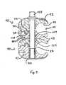
- the anti-rotation devicecan also be a flexible synthetic foam element 199 as per FIG. 8 . Only upon the tightening of screw 103 the anti-rotation device 199 interlock and determine the angle position of the articulation element.
- the advantageis that its material on the bottom and lid surfaces 197 is harder and, in particular, can also be structured or span hard inserts to engage in a ringshaped step.
- the clamping element 10is then designed similar to the embodiment per FIG. 1 , only the depth and the sidewalls are intended to receive the anti-rotation device 199. In the cylinder area, the element 199 is flexible to be compressed when screw 103 is tightened.
- the anti-twisting deviceis beveled and has conical slants 196 between the surface 195 and the lid or the floor area 197.
- the material in the floor and lid area of the anti-rotation device 199is harder than the material of the clamping elements utilized, and in the solid material preferably consists of a flexible, compressible material, particularly synthetic foam.
- the diameter of the anti-rotation device 90 or 199is 30 millimeters and the contact surface (radial width) for the outer rim 94 is 3 millimeters.
- the structures (ridges)can also be integrated in the material of the clamping jaw 13, for instance radial grooves.
- FIG. 9shows a screw 103 which is to be inserted through the aligned bores, which can sit on the conical screw receptacle 23 with its conical flange 104.
- screw 103for instance has a square drive head 105.
- the shoulder 104is designed to be complementary to the receptacle 23.
- a nut 106is attached from the other side.
- the nut 106has a slightly conical sleeve 107 and a conical flange 108 as a covering cap.
- the shape of flange 108corresponds to the shape of screw receptacle 23 of clamping element 10 or 20.
- the sleeve 107is inserted into one bore and, to the best advantage, protrudes into the other bore and / or through it.
- the sleeve 107is fitted in the press fit; additionally, it can also have an external thread. It can be designed as a fit for one of the internal threads used in bore.
- a clamping elementis equipped with a tilting, but torsion rigid, bearing for the nut.
- the clamping jaw 12again has the conically opening bore.
- This borehas a recess on the side facing away from the cavity 11, which can be a rectangular slit in particular.
- the cylindrical nutis inserted in the recess.
- a toleranceexists through the cylindrical nut, so that when a rod 102 is clipped into cavity 11 the top part 12 of the clamping element can be tilted as well.
- ithas an appendage or projection, which protrudes into the said recess with lateral tolerance.
- the projectionhas a tolerance in the recess to permit the tilting motion of top part 12.
- the nut with projectionother design versions are possible, for instance, an L-shaped flattened nut, which, for example, has wobble rivets and is punched, so that an appendage protrudes into a corresponding nut in top part 12 and produces the torsion rigidity.
- the nut 106has an internal thread that fits the complementary external thread of screw 103.
- screw 103 opposite nut 106Through the tightening of screw 103 opposite nut 106, the two clamping elements 10 and 20 are pulled together. Then, by exerting pressure, a rod can be inserted laterally in the respective cavity. Since the diameters of the rods are larger than the opening at the free ends, it is protected from falling out. Through a roughening of grooves 14, not illustrated in the drawings, it is also protected from a simple longitudinal displacement.
- clamping jaws 12 and 13are moved closer towards one another against the resetting force of the hinge bearing 17 and are finally completely blocked in their angled position through the use of the plate of anti-rotation device 90 placed between the clamp elements. At the same time, this fully secures the rods in grooves 14 against longitudinal displacement as well as against twisting by minimizing the cavity 11. While self-locking screw 109 is not illustrated, it can be utilized here as well.
- the nut 106is designed as a continuous sleeve.
- the anti-rotation device 90has impressed itself into the softer material of jaw 13. Said impression makes it preferable - with the exception of an immediate tightening of the screw in this or another place of an external fixator clamping element used for the same patient - to use said clamping element only once and to throw it away after use.
- the material used for the clampmay be PEEK (Poly Esther Ether Ketone), and may have chopped carbon fiber reinforcement for extra strength. This allows the two pieces of the polymeric clamp to be injection molded.
- the pressed in traces of the anti-rotation device in the stepis a sign of use for the clamping element, so that the user can see that the reuse of the product can be excluded.
- a screw 103instead of a screw 103, another locking device can be used, for instance a clamping lever or a bayonet catch.
- a clamping elementis an object of the invention, which has the bore and nut per FIG. 3 , a counter nut 109 per FIG. 9 and non-skid elements 99 for the rods per FIG. 8 or a part thereof.
- a corresponding articulation elementcan be comprised of any two random above-mentioned clamping elements, if they can be utilized for the selected anti-rotation device.
Landscapes
- Health & Medical Sciences (AREA)
- Orthopedic Medicine & Surgery (AREA)
- Surgery (AREA)
- Life Sciences & Earth Sciences (AREA)
- Engineering & Computer Science (AREA)
- Medical Informatics (AREA)
- Biomedical Technology (AREA)
- Heart & Thoracic Surgery (AREA)
- Nuclear Medicine, Radiotherapy & Molecular Imaging (AREA)
- Molecular Biology (AREA)
- Animal Behavior & Ethology (AREA)
- General Health & Medical Sciences (AREA)
- Public Health (AREA)
- Veterinary Medicine (AREA)
- General Engineering & Computer Science (AREA)
- Mechanical Engineering (AREA)
- Surgical Instruments (AREA)
Description
- The invention pertains to a clamping element for the clamping of a rod-shaped element of an articulation, element particularly a clamping element of an articulation element for the stabilization of bone fractures according to the preamble of claim 1. The invention also pertains to an articulation element with two clamping elements and with one at least two-piece locking device, and optionally an anti-rotation device.
EP 1 184 000 describes a single-piece clamping element with two opposing cavities and one laterally open cavity to receive a clamping jaw forming a rod-shaped element and a hinge, which is arranged opposite the cavity, connecting the clamping jaws so that they are movable on top of each other, with each clamping jaw having one bore each aligned flush with one another.- This clamping element has the advantage that an articulation can be produced with two identical clamping elements arranged next to one another, inserting a connecting screw through the bore, which is screwed into an internally threaded nut to close the clamping jaws.
- From
EP-A-0 700 664 an articulation is known consisting of two times two individual clamping jaw elements and one central screw. This articulation allows the lateral insertion of one or two rod-shaped elements into the corresponding cavities.U.S. Patent No. 5,752,954 has a spring arranged between the two center clamping jaw elements, which spring tension allows the clipping in of the rod-shaped elements and holding the jaw elements on the rod-shaped elements before the articulation element is blocked.U.S. Patent No. 6,616,664 provides for narrow lateral lever arms to hold laterally inserted rod-shaped elements before the articulation is blocked.U.S. Patent No. 6,342,054 has an external spring. - Based on this state of technology, it is one role of the invention at hand to indicate a two-piece clamping element which allows the lateral insertion of a rod-shaped element and which, when utilized dually, is directly applicable as an articulation element. It is another object of the invention to obtain a two-piece clamping element with advantages of a single-piece clamping element, e.g. the working connection of the two clamping jaws.
- Another goal of the invention is the creation of a cost-effective disposable clamping element, particularly made of a synthetic material (such as plastic) injection molding, which does not have the structural disadvantages of X-ray transparent clamping elements as in
EP 1 184 000 . Especially it is an object of the invention to realize a disposable clamping element being able to support and transmit large pressure forces. US 2002/026190 , later on matured toUS 6,616,664 mentioned above, discloses a clamping element with the features of the preamble of claim 1. Said known clamping element uses mating surfaces between the lower jaw portion and the fastener together with a relieved portion in the lower jaw portion for a pivoting movement between the lower jaw and the fastener.- Based on the known state of technology, another role of the invention is also to provide an improved articulation element.
- A two-piece clamping element is provided comprising two separate opposing first and second clamping jaws forming a laterally open cavity to receive a rod-shaped element, with each clamping jaw having a bore aligned with one another.
- A pivot bearing is arranged opposite the cavity bringing the two opposing clamping jaws in contact to one another and thereby making them movable towards and away from one another. Each clamping jaw has a bore, aligned with one another. The bores are arranged between the cavity and the pivot bearing.
- A first clamping jaw has an anti-rotation device on its exterior or a receptacle for receiving an anti-rotation device.
- An articulation element can be formed from two clamping elements in which the clamping elements are arranged on top of one another with their first clamping jaws adjacent one another. The articulation element has one at least two-piece locking shaft with a first part of the locking shaft insertable through a bore of the second clamping jaw of one clamping element, and with a second part of the locking shaft insertable through a bore of the first clamping jaw of the other clamping element. One or the other or both parts of the locking shaft being able to be brought in contact with one another through the bores in the first clamping jaws. The first and second clamping jaws of the clamping elements can be blocked with the locking device. The articulation element has an anti-rotation device is arranged between the first clamping jaws that are arranged on top of one another, the anti-rotation device having a central bore. The anti-rotation device is preferably a plate whose material is preferably harder than the material of the clamping elements and which has ridges formed on both sides of the plate. The anti-rotation device can also be a cylinder whose material in a floor and a lid area thereof is preferably harder than the material of the clamping elements, and which preferably consists of a flexible, compressible material in the solid material part, in particular synthetic foam. The locking device includes a cylindrical screw and a conical nut, the conical nut preferably has a stop shoulder for a self-locking screw, which can be inserted in an internal thread in the cylindrical screw. A hollow spring enveloping the locking device is used as an anti-rotation device or as an additional anti-rotation device.
- By equipping the two-piece clamping elements with functionally different first and second clamping jaws, two clamping elements can be placed on top of one another each with their first clamping jaws, to form an articulation element in a simple manner.
- Now the invention is more closely described with reference to the drawings and with the aid of a number of embodiments:
- FIG. 1
- shows a perspective view of an articulation element with two clamping elements per a first embodiment of the invention,
- FIG. 2
- shows a different perspective view of the articulation element of
FIG. 1 , - FIG. 3
- shows a cross-section view of the articulation element of
FIG. 1 or 2 , - FIG. 4
- shows a perspective view of an articulation element with two clamping elements per a second embodiment of the invention,
- FIG. 5
- shows a different perspective view of the articulation element of
FIG. 4 , - FIG. 6
- shows a cross-section view of the articulation element of
FIG. 4 or 5 , - FIG. 7
- shows a top view of an anti-rotation device for an articulation element per
FIG. 1 or4 , - FIG. 8
- shows a perspective view of another anti-rotation device for an articulation element, and
- FIG. 9
- shows a partially sectioned lateral view of a part of a locking screw, a nut and a self-locking bolt for an articulation element per one of the
FIG. 1 to 6 . FIGS. 1 to 3 show a first embodiment of an articulation element with twoclamping elements 10 per the invention.FIGS. 1 and 2 show two perspective views at different angles from the top. The two-part clamping element 10 has twoclamping jaws grooves 14. Theouter edges 16 of the side facingclamping jaws outer edges 16, apivotal bearing 17 is arranged, comprising complementary pivotal surfaces comprisingsemi-cylindrical portions 36 andcomplementary grooves 38 contactingclamping jaws - When the
clamping element 10 is intended for a rod with 4 to 6 millimeters in diameter, the opening at the free ends has a diameter of, for instance, 2 millimeters in a resting position. If theclamping element 10 is intended for a rod with a diameter of 12 millimeters, the opening at the free ends has a diameter of, for instance, 9 millimeters in a resting position. - In the upper area of the
clamping jaw 12 the area betweencross ribs 21 has been excluded with the exception of around screw receptacle 23. Screwreceptacle 23, for instance, has a conical shoulder area or a step shoulder, whose purpose will be described later, which merges into a continuous bore in thetop clamping jaw 12, which can be seen inFIG 3 . - In the
lower clamping jaw 13cross ribs 21 end in aring flange 22, which, for instance, may have a flat recessed ring shaped step, where a weight and material saving recess advantageous for injection molding can be connected, with a bore in the center. - This continuous bore is aligned flush with the abovementioned bore in
top clamping jaw 12. At the clampingelement 10, it runs vertically to the axis of the cavity 11. The bore is cylindrical and in its interior, it may have guide ribs arranged in regular intervals. Of course, the number of guide ribs may be chosen freely, preferably between three or five ribs. - One
clamping element 10 with thejaw parts semi-cylindrical portions 36 running over the whole width of thejaw 12 and being directed to acomplementary groove 38 injaw 13. The stops 36 and 38 may be chosen shorter or in smaller portions with intermediate regions; however, the shown embodiment providing for a longpivotal bearing 17 is preferred. The stops 36 and 38 are running parallel to the cavity 11. Between thestops pin 136 and a corresponding reception bore 138. Thepin 136 can be seen in the cross-sectional view ofFIG. 3 , entering with play into the reception bore 138, to ensure that thejaws elements pin 136 can be symmetrical in view of his main axis but is preferably oblong in the transverse direction, e.g. parallel tosurfaces 36 andgroove 14. FIGS. 4 to 6 show a second embodiment of an articulation element with two clampingelements 20 per the invention.FIGS. 4 and 5 show two perspective views at different angles from the top. The two-part clamping element 20 has two clampingjaws grooves 14. Across from the cavity 11, apivotal bearing 17 is arranged, comprising complementary pivotal surfaces comprisingsemi-cylindrical portions 36 andcomplementary grooves 38 contacting clampingjaws - One
clamping element 20 with thejaw parts semi-cylindrical portions 36 running on the left and on the right side of apassage 238 of thejaw 12 and being directed to twocomplementary groove portions 38 on both sides of ablocking pin 236 injaw 13. The stops surfaces 36 and 38 may also be chosen shorter; however, the shown embodiment providing for two rather long pivotal bearing surfaces 17 is preferred. The blockingpin 236 and the corresponding reception bore 238 are provided on the outer open side of thejaws pin 236 is - seen from above - rectangular to ensure that thejaws element 20 can not rotate one against the other. - In the first embodiment of
FIG. 1 to 3 thepin 136 is provided in thejaw 12 whereas in the second embodiment ofFIG. 4 to 6 theblocking pin 236 is provided in thejaw 13. This clearly shows that the features of the two embodiments can be mixed, the blockingpin 236 ofFIG. 4 can be used withinjaw 12 and thepin 136 ofFIG. 1 can be used withinjaw 13 with the complementary bores in theother jaws - A spiral or
coil spring 119 is arranged between the two clampingelements spring receptacle 121. Thespring receptacle 121 can form a hemispherical area; it can also be level and smooth; in particular, it can be rough to ensure a greater resistance of thespring 119 against twisting. Thespring 119 pushes the two clampingelements elements jaws grooves 14. Thespring 119 can also be a disk spring package or another resilient element. FIG. 7 shows a top view of an anti-rotation device 90 for an articulation element perFIG. 1 . Anti-rotation device 90, for instance, is a thin metal plate with a central bore 91, a hub 92 andspokes 93. Theouter rim 94, for instance, has successive puncturedridges 95 and recesses 96. For instance, they are arranged so thatrecesses 96 are always arranged opposite the sixspokes 93 in this case, with each of theridges 95 located intermittently.- It is clear that, a simple punching process to manufacture the plates of the anti-rotation device 90 is used, that
ridges 95 seen from above are recesses seen from below.Punctured ridges 95 and recesses 96 can be round, pyramidal or polygon shaped. They can run radially side by side in several rows, in a larger number than inFIG. 7 etc. In another alternate design, radial ribs can be used as well. - The anti-rotation device 90 is to be positioned between the two clamping
elements position 190 as indicated inFIG. 1, 2 ,4 and 5 .FIG. 3 and6 show that an anti-rotation device can also be achieved through the design of the material of thefirst clamping jaw 13, comprising rough elements to avoid rotation between the contactingjaws 13. - The anti-rotation device can also be a flexible synthetic foam element 199 as per
FIG. 8 . Only upon the tightening ofscrew 103 the anti-rotation device 199 interlock and determine the angle position of the articulation element. - This is a flexible cylindrical element 199 with a central bore 198 for receiving
screw 103. It can be used in the place of an anti-rotation device 90. The advantage is that its material on the bottom and lid surfaces 197 is harder and, in particular, can also be structured or span hard inserts to engage in a ringshaped step. The clampingelement 10 is then designed similar to the embodiment perFIG. 1 , only the depth and the sidewalls are intended to receive the anti-rotation device 199. In the cylinder area, the element 199 is flexible to be compressed whenscrew 103 is tightened. The anti-twisting device is beveled and has conical slants 196 between thesurface 195 and the lid or thefloor area 197. - It is advantageous that the material in the floor and lid area of the anti-rotation device 199 is harder than the material of the clamping elements utilized, and in the solid material preferably consists of a flexible, compressible material, particularly synthetic foam.
- The diameter of the anti-rotation device 90 or 199 is 30 millimeters and the contact surface (radial width) for the
outer rim 94 is 3 millimeters. Instead of placing the ridges on element 90, the structures (ridges) can also be integrated in the material of the clampingjaw 13, for instance radial grooves. FIG. 9 shows ascrew 103 which is to be inserted through the aligned bores, which can sit on theconical screw receptacle 23 with its conical flange 104. For tightening, screw 103 for instance has a square drive head 105. It is clear that instead of a square, a hexagon or a slit etc. can be utilized. Preferably, the shoulder 104 is designed to be complementary to thereceptacle 23. Anut 106 is attached from the other side. Thenut 106 has a slightlyconical sleeve 107 and a conical flange 108 as a covering cap. The shape of flange 108 corresponds to the shape ofscrew receptacle 23 of clampingelement sleeve 107 is inserted into one bore and, to the best advantage, protrudes into the other bore and / or through it. Thesleeve 107 is fitted in the press fit; additionally, it can also have an external thread. It can be designed as a fit for one of the internal threads used in bore.- In another design version, not illustrated in the drawings, a clamping element is equipped with a tilting, but torsion rigid, bearing for the nut. The clamping
jaw 12 again has the conically opening bore. This bore, however, has a recess on the side facing away from the cavity 11, which can be a rectangular slit in particular. During the assembly, the cylindrical nut is inserted in the recess. A tolerance exists through the cylindrical nut, so that when a rod 102 is clipped into cavity 11 thetop part 12 of the clamping element can be tilted as well. In order to ensure the fixation ofscrew 103 and to design the nut torsionally rigid, it has an appendage or projection, which protrudes into the said recess with lateral tolerance. In a lateral view of the clamping element, the projection has a tolerance in the recess to permit the tilting motion oftop part 12. In addition to the nut with projection, other design versions are possible, for instance, an L-shaped flattened nut, which, for example, has wobble rivets and is punched, so that an appendage protrudes into a corresponding nut intop part 12 and produces the torsion rigidity. - The
nut 106 has an internal thread that fits the complementary external thread ofscrew 103. Through the tightening ofscrew 103opposite nut 106, the two clampingelements grooves 14, not illustrated in the drawings, it is also protected from a simple longitudinal displacement. - If
screw 103 is tightened further, clampingjaws grooves 14 against longitudinal displacement as well as against twisting by minimizing the cavity 11. While self-locking screw 109 is not illustrated, it can be utilized here as well. Preferably thenut 106 is designed as a continuous sleeve. - When
screw 103 is opened,nut 106 remains in the one clamping element. The anti-rotation device 90 has impressed itself into the softer material ofjaw 13. Said impression makes it preferable - with the exception of an immediate tightening of the screw in this or another place of an external fixator clamping element used for the same patient - to use said clamping element only once and to throw it away after use. The material used for the clamp may be PEEK (Poly Esther Ether Ketone), and may have chopped carbon fiber reinforcement for extra strength. This allows the two pieces of the polymeric clamp to be injection molded. The pressed in traces of the anti-rotation device in the step is a sign of use for the clamping element, so that the user can see that the reuse of the product can be excluded. - In the resting position of the clamping
elements jaws slit 27 is reduced. Whenscrew 103 is tightened, the slit is minimized. Through the central transfer of force via the screw and nut elements 104 and 108 on the identical areas, theslit 27 is minimized in its thickness until thegroove 14 contacts the rod in the cavity 11. Then the (upper) clampingjaw 12 with theribs 21 deviates around the rod and thesemi-cylindrical region 36 touches down on thecomplementary area 38. Whenscrew 103 is tightened further, the blocking effect sets in as of this time and the unit semi-cylindrical region 36 -complementary area 38 takes over the bearing function. - Instead of a
screw 103, another locking device can be used, for instance a clamping lever or a bayonet catch. - It is emphasized that the term embodiment in the previously mentioned description does not mean that only the elements described with respect to the respective clamping element or articulation element are subject of the invention. In particular, these are also combinations of the characteristics described in objects of various embodiments and FIGS. For instance, a clamping element is an object of the invention, which has the bore and nut per
FIG. 3 , a counter nut 109 perFIG. 9 and non-skid elements 99 for the rods perFIG. 8 or a part thereof. A corresponding articulation element can be comprised of any two random above-mentioned clamping elements, if they can be utilized for the selected anti-rotation device. - Although the invention herein has been described with reference to particular embodiments, it is to be understood that these embodiments are merely illustrative of the principles and applications of the present invention. It is therefore to be understood that numerous modifications may be made to the illustrative embodiments and that other arrangements may be devised without departing from the spirit and scope of the present invention as defined by the appended claims.
Claims (10)
- A two-piece clamping element (10, 20) comprising two separate opposing first and second clamping jaws (12, 13) forming a laterally open cavity (11) to receive a rod-shaped element, with each clamping jaw (12, 13) having a bore aligned with one another to accommodate a locking shaft (103) of a locking device, wherein the bore of the locking shaft (103) is arranged between said cavity (11) and a pivot bearing (17) allowing the two opposing clamping jaws (12, 13) to come into contact with one another,characterized in that the pivot bearing (17) comprises at least one set of complementary bearing surfaces portions (36, 38) encompassing semi-cylindrical portions (36) and complementary grooves (38).
- The clamping element as set forth in claim 1, wherein a rotation avoiding pin (136, 236) is provided in one of the jaws (12 or 13) whereas a corresponding similar reception bore (138, 238) for the rotation avoiding pin (136, 236) is arranged in the other of the jaws (13, or 12, respectively).
- The clamping element as set forth in claim 2, wherein the rotation avoiding pin (136) is provided between the complementary bearing surfaces portions (36, 38) and cavity (11).
- The clamping element as set forth in claim 2, wherein the rotation avoiding pin (236) is arranged such to divide the complementary bearing surfaces portions (36, 38) in two side parts.
- The clamping element as set forth in one of claims 1 to 4, wherein a first clamping jaw (13) has an anti-rotation device (90, 199) on its exterior or a receptacle for receiving an anti-rotation device (90, 199).
- An articulation element having first and second clamping elements (10, 20) as set forth in one of claims 1 to 5, which clamping elements (10, 20) are arranged on top of one another with their first clamping jaws (13) adjacent one another, comprising a spring (119) provided between the two clamping elements (10, 20) and having an at least two-piece locking device (103, 106, 109) with a first part (103) of the locking shaft insertable through a bore of the second clamping jaw (12) of the first clamping element (10, 20), and with a second part (106) of the locking device insertable through a bore of the first clamping jaw (13) of the second clamping element (10, 20), and with one or the other or both parts (103, 106) being able to be brought in contact with one another through the bores in the first clamping jaws (13), and where the first and second clamping jaws (13, 12) of the first and second clamping elements (10, 20) can be blocked with the locking device.
- The articulation element as set forth in claim 6, wherein an anti-rotation (90, 199) device is arranged between the first clamping jaws (13) that are arranged on top of one another, the anti-rotation device having a central bore (91, 198).
- The articulation element as set forth in claim 7, wherein the anti-rotation device (90) is a plate whose material is harder than the material of the clamping elements and which has ridges formed on both sides of the plate.
- The articulation element as set forth in claim 7, wherein the anti-rotation device is a cylinder (199) whose material in a floor and a lid area is preferably harder than the material of the clamping elements, and which consists of a flexible, compressible material in the solid material part, in particular synthetic foam.
- The articulation element as set forth in one of claims 7 to 9, wherein the spring is a hollow spring (119) enveloping the locking device which is used as an anti-rotation device or as an additional anti-rotation device.
Priority Applications (7)
| Application Number | Priority Date | Filing Date | Title |
|---|---|---|---|
| ES06110244TES2330779T3 (en) | 2006-02-21 | 2006-02-21 | TIGHTENING AND ARTICULATION ELEMENT. |
| EP06110244AEP1820461B1 (en) | 2006-02-21 | 2006-02-21 | Clamping and articulation element |
| DE602006008266TDE602006008266D1 (en) | 2006-02-21 | 2006-02-21 | Clamping and joint element |
| US11/641,600US8523923B2 (en) | 2006-02-21 | 2006-12-19 | Clamping and articulation element |
| AU2007200480AAU2007200480B2 (en) | 2006-02-21 | 2007-02-05 | Clamping and articulation element |
| JP2007039108AJP4639206B2 (en) | 2006-02-21 | 2007-02-20 | Clamp and joint element |
| US13/937,704US8840653B2 (en) | 2006-02-21 | 2013-07-09 | Clamping and articulation element |
Applications Claiming Priority (1)
| Application Number | Priority Date | Filing Date | Title |
|---|---|---|---|
| EP06110244AEP1820461B1 (en) | 2006-02-21 | 2006-02-21 | Clamping and articulation element |
Publications (2)
| Publication Number | Publication Date |
|---|---|
| EP1820461A1 EP1820461A1 (en) | 2007-08-22 |
| EP1820461B1true EP1820461B1 (en) | 2009-08-05 |
Family
ID=36698860
Family Applications (1)
| Application Number | Title | Priority Date | Filing Date |
|---|---|---|---|
| EP06110244ANot-in-forceEP1820461B1 (en) | 2006-02-21 | 2006-02-21 | Clamping and articulation element |
Country Status (6)
| Country | Link |
|---|---|
| US (2) | US8523923B2 (en) |
| EP (1) | EP1820461B1 (en) |
| JP (1) | JP4639206B2 (en) |
| AU (1) | AU2007200480B2 (en) |
| DE (1) | DE602006008266D1 (en) |
| ES (1) | ES2330779T3 (en) |
Families Citing this family (48)
| Publication number | Priority date | Publication date | Assignee | Title |
|---|---|---|---|---|
| US7708736B2 (en) | 2006-02-22 | 2010-05-04 | Extraortho, Inc. | Articulation apparatus for external fixation device |
| EP1920720B1 (en)* | 2006-10-13 | 2014-03-19 | Stryker Trauma SA | Prevention of re-use of a medical device |
| GB2444907A (en)* | 2006-12-20 | 2008-06-25 | Promedics Ltd | A joint fixator |
| EP2197372B1 (en) | 2007-09-27 | 2016-04-13 | Zimmer, Inc. | Clamping apparatus for external fixation and stabilization |
| US8292924B2 (en)* | 2007-10-05 | 2012-10-23 | Spineworks, Llc | Enhanced pedicle rod clamp device |
| WO2010090428A2 (en)* | 2009-02-03 | 2010-08-12 | Yoo Eun Hee | Spinal support rod comprising artificial spinal support and ball joint connector |
| ES2451507T3 (en) | 2009-05-15 | 2014-03-27 | Stryker Trauma Ag | Fixing flange |
| IT1396145B1 (en)* | 2009-11-05 | 2012-11-16 | Citieffe Srl | MULTI-PURPOSE EXTERNAL FIXER. |
| US9138260B2 (en) | 2010-07-01 | 2015-09-22 | Zimmer, Inc. | Multi-locking external fixation clamp |
| US8973711B2 (en)* | 2010-08-31 | 2015-03-10 | Deltak Manufacturing, Inc. | Intermediate scaffold joint |
| WO2012051255A1 (en) | 2010-10-12 | 2012-04-19 | Extraortho, Inc. | External fixation surgical clamp with swivel |
| WO2012051312A1 (en)* | 2010-10-12 | 2012-04-19 | Extraortho, Inc. | Single lock external fixation clamp arrangement |
| US8728078B2 (en) | 2010-11-04 | 2014-05-20 | Zimmer, Inc. | Clamping assembly with links |
| WO2012078897A1 (en) | 2010-12-09 | 2012-06-14 | Extraortho, Inc. | Revolving lock for external fixation clamps |
| EP2648633B1 (en) | 2010-12-09 | 2016-05-18 | Zimmer, Inc. | External fixation clamp with cam driven jaw |
| ES2540256T3 (en) | 2010-12-14 | 2015-07-09 | Stryker Trauma Sa | Fixing clamp |
| EP2465454B1 (en)* | 2010-12-14 | 2015-04-08 | Stryker Trauma SA | Fixation clamp with thumbwheel |
| USD704840S1 (en) | 2010-12-14 | 2014-05-13 | Stryker Trauma Sa | Hinge coupling |
| USD683461S1 (en) | 2010-12-14 | 2013-05-28 | Stryker Trauma Sa | Hinge coupling |
| EP2465455B1 (en) | 2010-12-14 | 2015-04-08 | Stryker Trauma SA | Fixation clamp |
| USD720853S1 (en) | 2010-12-14 | 2015-01-06 | Stryker Trauma Sa | Fixation clamp |
| US8992579B1 (en)* | 2011-03-08 | 2015-03-31 | Nuvasive, Inc. | Lateral fixation constructs and related methods |
| JP6106662B2 (en) | 2011-05-17 | 2017-04-05 | ジンマー,インコーポレイティド | External fixed clamping system using a starting mechanism and stored spring energy |
| USD682426S1 (en) | 2011-06-14 | 2013-05-14 | Stryker Trauma Sa | Fixation clamp |
| USD663030S1 (en)* | 2011-06-14 | 2012-07-03 | Styker Trauma SA | Fixation clamp |
| US9060815B1 (en) | 2012-03-08 | 2015-06-23 | Nuvasive, Inc. | Systems and methods for performing spine surgery |
| KR101182784B1 (en)* | 2012-06-05 | 2012-09-13 | 한국뉴매틱(주) | C-type clamping device |
| ITBO20120400A1 (en)* | 2012-07-24 | 2014-01-25 | Citieffe Srl | CLAMP FOR EXTERNAL FIXATORS |
| US9945580B2 (en)* | 2012-08-28 | 2018-04-17 | Broan-Nutone, Llc | Ventilation system |
| US10619791B2 (en) | 2013-03-14 | 2020-04-14 | Eaton Intelligent Power Limited | Channel framing with additional functional side |
| US9517089B1 (en) | 2013-10-08 | 2016-12-13 | Nuvasive, Inc. | Bone anchor with offset rod connector |
| CA2875556C (en) | 2013-12-23 | 2022-07-12 | Cooper Technologies Company | Fastener nut for channel framing |
| CN104622526B (en)* | 2014-02-22 | 2019-09-13 | 宋若怡 | Elastic skin expander and its skin traction system, hook bar fixation system |
| CA2890064C (en) | 2014-04-30 | 2022-08-16 | Cooper Technologies Company | Trapeze hanger system including twist-locking fitting |
| CA2889176C (en) | 2014-04-30 | 2022-08-16 | Cooper Technologies Company | Trapeze hanger system including trapeze hanger fitting |
| CA2889880C (en) | 2014-05-02 | 2022-05-31 | Cooper Technologies Company | Conduit clamp for strut channel |
| CA2889168C (en) | 2014-05-02 | 2022-09-20 | Cooper Technologies Company | Strut system and strut fitting therefor |
| US9347213B1 (en) | 2014-11-14 | 2016-05-24 | Cooper Technologies Company | Fitting for channel framing |
| US9982695B2 (en) | 2014-11-14 | 2018-05-29 | Cooper Technologies Company | Fitting for strut channel |
| US10100861B2 (en) | 2014-11-14 | 2018-10-16 | Cooper Technologies Company | Beam clamp for strut channel |
| US9926957B2 (en) | 2014-11-14 | 2018-03-27 | Cooper Technologies Company | Fitting for strut channel |
| US20160136836A1 (en)* | 2014-11-18 | 2016-05-19 | Jessem Products Limited | Stock guide assembly |
| US10531896B2 (en)* | 2015-08-10 | 2020-01-14 | Stryker European Holdings I, Llc | Distraction tube with wire clamp |
| US10568662B2 (en)* | 2017-10-12 | 2020-02-25 | The Orthopaedic Implant Company | Orthopedic clamping devices |
| US10945765B2 (en) | 2017-12-06 | 2021-03-16 | Austin Miller Trauma LLC | Fixation clamp with spacer |
| DE102018005026A1 (en)* | 2018-06-26 | 2020-01-02 | Björn Blisse | FASTENING CLAMP HOLDER AND USE |
| RU194458U1 (en)* | 2019-06-03 | 2019-12-11 | Общество С Ограниченной Ответственностью "Орто-Сув" | DEVICE FOR FIXING BONE FRAGMENTS |
| US12274476B2 (en)* | 2020-02-18 | 2025-04-15 | Wright Medical Technology, Inc. | Bone fixation device |
Citations (1)
| Publication number | Priority date | Publication date | Assignee | Title |
|---|---|---|---|---|
| FR2528921A1 (en)* | 1982-06-21 | 1983-12-23 | Maillet Expositions Sa | Connecting clamp for hollow section tubes - has central hinge and cylindrical rubber return spring for jaws |
Family Cites Families (32)
| Publication number | Priority date | Publication date | Assignee | Title |
|---|---|---|---|---|
| FR1604790A (en)* | 1968-11-05 | 1972-01-31 | ||
| US4483334A (en) | 1983-04-11 | 1984-11-20 | Murray William M | External fixation device |
| FR2577793B1 (en)* | 1985-02-22 | 1989-04-21 | Realisations Electro Mecanique | EXTERNAL FIXER DEVICE FOR ORTHOPEDIC USE |
| US4620533A (en) | 1985-09-16 | 1986-11-04 | Pfizer Hospital Products Group Inc. | External bone fixation apparatus |
| US4648388B1 (en) | 1985-11-01 | 1995-10-31 | Acromed Corp | Apparatus and method for maintaining vertebrae in a desired relationship |
| CH683963A5 (en)* | 1988-06-10 | 1994-06-30 | Synthes Ag | Internal fixation. |
| JPH0313539U (en)* | 1989-06-21 | 1991-02-12 | ||
| US5290288A (en)* | 1990-02-08 | 1994-03-01 | Vignaud Jean Louis | Multi-function device for the osteosynthesis of rachis |
| US5810817A (en)* | 1992-06-19 | 1998-09-22 | Roussouly; Pierre | Spinal therapy apparatus |
| FR2697742B1 (en)* | 1992-11-06 | 1994-12-16 | Biomat | Osteosynthesis device for spinal consolidation. |
| US5285556A (en) | 1992-12-14 | 1994-02-15 | Shorin Joseph E | Integral polymeric clamp |
| US5947965A (en) | 1992-12-31 | 1999-09-07 | Bryan; Donald W. | Spinal fixation apparatus and method |
| CH690293A5 (en) | 1994-09-06 | 2000-07-14 | Jaquet Orthopedie | Joint for components of an external fixator. |
| FR2731344B1 (en) | 1995-03-06 | 1997-08-22 | Dimso Sa | SPINAL INSTRUMENTATION ESPECIALLY FOR A ROD |
| ES2202492T3 (en)* | 1996-03-25 | 2004-04-01 | Synthes Ag Chur | ADJUSTABLE CLAMP FOR BONE FIXING ELEMENTS. |
| IES77331B2 (en)* | 1997-06-03 | 1997-12-03 | Tecos Holdings Inc | Pluridirectional and modulable vertebral osteosynthesis device of small overall size |
| US6749361B2 (en) | 1997-10-06 | 2004-06-15 | Werner Hermann | Shackle element for clamping a fixation rod, a method for making a shackle element, a hook with a shackle element and a rode connector with a shackle element |
| EP0838196A3 (en)* | 1997-11-30 | 1998-07-01 | Daniel Spitzer | Clamping connector for medical tools and apparatus |
| EP0933065A1 (en)* | 1998-02-02 | 1999-08-04 | Sulzer Orthopädie AG | Pivotable attachment system for a bone screw |
| AUPP396598A0 (en) | 1998-06-09 | 1998-07-02 | Pine Ridge Holdings Pty Ltd | Single action clamp |
| FR2787697B1 (en)* | 1998-12-29 | 2001-06-15 | France Etat | MONOLATERAL ORTHOPEDIC EXTERNAL FIXATION DEVICE FOR BONE FRACTURE IMMOBILIZATION |
| CH693164A5 (en) | 1998-12-29 | 2003-03-27 | Stryker Trauma Sa | A locating and locking. |
| US6616664B2 (en) | 1999-10-21 | 2003-09-09 | Ebi L.P. | Clamp assembly for an external fixation system |
| US6277119B1 (en) | 1999-10-21 | 2001-08-21 | Electro-Biology, Inc. | External fixation system |
| FR2804314B1 (en) | 2000-01-27 | 2003-01-31 | Scientx | INTERVERTEBRAL CONNECTION DEVICE WITH A CONNECTION BAR FOR FIXING A CONNECTING ROD |
| US6872209B2 (en)* | 2000-03-15 | 2005-03-29 | Sdgi Holdings, Inc. | Spinal implant connection assembly |
| EP1184000A1 (en) | 2000-08-31 | 2002-03-06 | ORTHOFIX S.r.l. | External fixator for stabilizing bone fractures |
| US6565564B2 (en)* | 2000-12-14 | 2003-05-20 | Synthes U.S.A. | Multi-pin clamp and rod attachment |
| ATE484228T1 (en)* | 2001-05-23 | 2010-10-15 | Boss Instr Ltd | RETRACTOR CLAMP COMPOSITION |
| FR2829919B1 (en)* | 2001-09-26 | 2003-12-19 | Spine Next Sa | VERTEBRAL FIXATION DEVICE |
| US6842949B2 (en) | 2003-05-19 | 2005-01-18 | Robert E. Warren | U-shaped wire rope clamp |
| ES2326269T3 (en) | 2004-08-20 | 2009-10-06 | Stryker Trauma Sa | TIGHTENING ELEMENT AND GASKET ELEMENT. |
- 2006
- 2006-02-21EPEP06110244Apatent/EP1820461B1/ennot_activeNot-in-force
- 2006-02-21ESES06110244Tpatent/ES2330779T3/enactiveActive
- 2006-02-21DEDE602006008266Tpatent/DE602006008266D1/enactiveActive
- 2006-12-19USUS11/641,600patent/US8523923B2/enactiveActive
- 2007
- 2007-02-05AUAU2007200480Apatent/AU2007200480B2/enactiveActive
- 2007-02-20JPJP2007039108Apatent/JP4639206B2/ennot_activeExpired - Fee Related
- 2013
- 2013-07-09USUS13/937,704patent/US8840653B2/enactiveActive
Patent Citations (1)
| Publication number | Priority date | Publication date | Assignee | Title |
|---|---|---|---|---|
| FR2528921A1 (en)* | 1982-06-21 | 1983-12-23 | Maillet Expositions Sa | Connecting clamp for hollow section tubes - has central hinge and cylindrical rubber return spring for jaws |
Also Published As
| Publication number | Publication date |
|---|---|
| ES2330779T3 (en) | 2009-12-15 |
| US8840653B2 (en) | 2014-09-23 |
| EP1820461A1 (en) | 2007-08-22 |
| US8523923B2 (en) | 2013-09-03 |
| AU2007200480B2 (en) | 2012-02-02 |
| JP2007222623A (en) | 2007-09-06 |
| US20130331838A1 (en) | 2013-12-12 |
| JP4639206B2 (en) | 2011-02-23 |
| US20070198012A1 (en) | 2007-08-23 |
| AU2007200480A1 (en) | 2007-09-06 |
| DE602006008266D1 (en) | 2009-09-17 |
Similar Documents
| Publication | Publication Date | Title |
|---|---|---|
| EP1820461B1 (en) | Clamping and articulation element | |
| US7241074B2 (en) | Clamping and articulation element | |
| EP1900334B1 (en) | Bone anchoring device | |
| US11547458B2 (en) | Locking element for a polyaxial bone anchor, bone plate assembly and tool | |
| EP2586392B1 (en) | High angulation polyaxial bone anchoring device | |
| EP2046214B1 (en) | Clamping element | |
| EP1795134B1 (en) | Polyaxial screw for flexible rod | |
| EP2687171B1 (en) | Polyaxial bone anchoring device | |
| EP3047812B1 (en) | Polyaxial bone anchoring device | |
| EP2586391B1 (en) | A locking assembly for a polyaxial bone anchoring device | |
| EP2191780B1 (en) | Receiving part for receiving a rod for coupling the rod to a bone anchoring element and a bone anchoring device with such a receiving part | |
| AU2005203636B2 (en) | Clamp for multiple rod-shaped elements | |
| EP2468198A1 (en) | Bone anchoring device | |
| EP2022423A1 (en) | Bone anchoring device | |
| EP2609883A1 (en) | A receiving part for receiving a rod for coupling the rod to a bone anchoring element | |
| EP2135573A1 (en) | Bone anchoring device | |
| EP2826429A1 (en) | Polyaxial bone anchoring device | |
| GB2312624A (en) | Anchoring means for connecting a first or second rod to a bone | |
| KR20140074842A (en) | Anchoring member suitable for use in a polyaxial bone anchoring device and polyaxial bone anchoring device with an enlarged pivot angle to one side | |
| US8057523B2 (en) | Set screw with deformable member | |
| KR101486978B1 (en) | Bone fixation device |
Legal Events
| Date | Code | Title | Description |
|---|---|---|---|
| PUAI | Public reference made under article 153(3) epc to a published international application that has entered the european phase | Free format text:ORIGINAL CODE: 0009012 | |
| AK | Designated contracting states | Kind code of ref document:A1 Designated state(s):AT BE BG CH CY CZ DE DK EE ES FI FR GB GR HU IE IS IT LI LT LU LV MC NL PL PT RO SE SI SK TR | |
| AX | Request for extension of the european patent | Extension state:AL BA HR MK YU | |
| 17P | Request for examination filed | Effective date:20071010 | |
| 17Q | First examination report despatched | Effective date:20071112 | |
| AKX | Designation fees paid | Designated state(s):CH DE ES FR GB IT LI | |
| GRAP | Despatch of communication of intention to grant a patent | Free format text:ORIGINAL CODE: EPIDOSNIGR1 | |
| GRAS | Grant fee paid | Free format text:ORIGINAL CODE: EPIDOSNIGR3 | |
| GRAA | (expected) grant | Free format text:ORIGINAL CODE: 0009210 | |
| AK | Designated contracting states | Kind code of ref document:B1 Designated state(s):CH DE ES FR GB IT LI | |
| REG | Reference to a national code | Ref country code:GB Ref legal event code:FG4D | |
| REG | Reference to a national code | Ref country code:CH Ref legal event code:EP | |
| REF | Corresponds to: | Ref document number:602006008266 Country of ref document:DE Date of ref document:20090917 Kind code of ref document:P | |
| REG | Reference to a national code | Ref country code:CH Ref legal event code:NV Representative=s name:ISLER & PEDRAZZINI AG | |
| REG | Reference to a national code | Ref country code:ES Ref legal event code:FG2A Ref document number:2330779 Country of ref document:ES Kind code of ref document:T3 | |
| PLBE | No opposition filed within time limit | Free format text:ORIGINAL CODE: 0009261 | |
| STAA | Information on the status of an ep patent application or granted ep patent | Free format text:STATUS: NO OPPOSITION FILED WITHIN TIME LIMIT | |
| 26N | No opposition filed | Effective date:20100507 | |
| REG | Reference to a national code | Ref country code:FR Ref legal event code:PLFP Year of fee payment:10 | |
| PGFP | Annual fee paid to national office [announced via postgrant information from national office to epo] | Ref country code:ES Payment date:20150217 Year of fee payment:10 Ref country code:IT Payment date:20150226 Year of fee payment:10 | |
| REG | Reference to a national code | Ref country code:FR Ref legal event code:PLFP Year of fee payment:11 | |
| REG | Reference to a national code | Ref country code:CH Ref legal event code:PUE Owner name:STRYKER EUROPEAN HOLDINGS I, LLC, US Free format text:FORMER OWNER: STRYKER EUROPEAN HOLDINGS V, LLC, US Ref country code:CH Ref legal event code:PUE Owner name:STRYKER EUROPEAN HOLDINGS V, LLC, US Free format text:FORMER OWNER: STRYKER TRAUMA SA, CH | |
| REG | Reference to a national code | Ref country code:DE Ref legal event code:R082 Ref document number:602006008266 Country of ref document:DE Representative=s name:MAIWALD PATENTANWALTS- UND RECHTSANWALTSGESELL, DE Ref country code:DE Ref legal event code:R081 Ref document number:602006008266 Country of ref document:DE Owner name:STRYKER EUROPEAN OPERATIONS HOLDINGS LLC, KALA, US Free format text:FORMER OWNER: STRYKER EUROPEAN HOLDINGS V, LLC (N.D. GES. D. STAATES DELAWARE), KALAMAZOO, MICH., US Ref country code:DE Ref legal event code:R081 Ref document number:602006008266 Country of ref document:DE Owner name:STRYKER EUROPEAN OPERATIONS HOLDINGS LLC, KALA, US Free format text:FORMER OWNER: STRYKER TRAUMA S.A., SELZACH, CH Ref country code:DE Ref legal event code:R082 Ref document number:602006008266 Country of ref document:DE Representative=s name:MAIWALD PATENTANWALTSGESELLSCHAFT MBH, DE Ref country code:DE Ref legal event code:R081 Ref document number:602006008266 Country of ref document:DE Owner name:STRYKER EUROPEAN HOLDINGS I, LLC (N.D. GES. D., US Free format text:FORMER OWNER: STRYKER TRAUMA S.A., SELZACH, CH Ref country code:DE Ref legal event code:R081 Ref document number:602006008266 Country of ref document:DE Owner name:STRYKER EUROPEAN HOLDINGS I, LLC (N.D. GES. D., US Free format text:FORMER OWNER: STRYKER EUROPEAN HOLDINGS V, LLC (N.D. GES. D. STAATES DELAWARE), KALAMAZOO, MICH., US | |
| REG | Reference to a national code | Ref country code:FR Ref legal event code:TP Owner name:STRYKER EUROPEAN HOLDINGS I, LLC, US Effective date:20161003 | |
| REG | Reference to a national code | Ref country code:GB Ref legal event code:732E Free format text:REGISTERED BETWEEN 20161013 AND 20161019 | |
| REG | Reference to a national code | Ref country code:ES Ref legal event code:PC2A Owner name:STRYKER EUROPEAN HOLDINGS I, LLC Effective date:20161111 | |
| PG25 | Lapsed in a contracting state [announced via postgrant information from national office to epo] | Ref country code:IT Free format text:LAPSE BECAUSE OF NON-PAYMENT OF DUE FEES Effective date:20160221 | |
| REG | Reference to a national code | Ref country code:FR Ref legal event code:PLFP Year of fee payment:12 | |
| REG | Reference to a national code | Ref country code:FR Ref legal event code:PLFP Year of fee payment:13 | |
| PG25 | Lapsed in a contracting state [announced via postgrant information from national office to epo] | Ref country code:ES Free format text:LAPSE BECAUSE OF NON-PAYMENT OF DUE FEES Effective date:20160222 | |
| REG | Reference to a national code | Ref country code:ES Ref legal event code:FD2A Effective date:20181207 | |
| REG | Reference to a national code | Ref country code:CH Ref legal event code:PUE Owner name:STRYKER EUROPEANS OPERATIONS HOLDINGS LLC, US Free format text:FORMER OWNER: STRYKER EUROPEAN HOLDINGS I, LLC, US | |
| REG | Reference to a national code | Ref country code:CH Ref legal event code:PK Free format text:BERICHTIGUNG INHABER | |
| REG | Reference to a national code | Ref country code:DE Ref legal event code:R082 Ref document number:602006008266 Country of ref document:DE Representative=s name:MAIWALD PATENTANWALTS- UND RECHTSANWALTSGESELL, DE Ref country code:DE Ref legal event code:R081 Ref document number:602006008266 Country of ref document:DE Owner name:STRYKER EUROPEAN OPERATIONS HOLDINGS LLC, KALA, US Free format text:FORMER OWNER: STRYKER EUROPEAN HOLDINGS I, LLC (N.D. GES. D. STAATES DELAWARE), KALAMAZOO, MICH., US | |
| REG | Reference to a national code | Ref country code:GB Ref legal event code:732E Free format text:REGISTERED BETWEEN 20210408 AND 20210414 | |
| PGFP | Annual fee paid to national office [announced via postgrant information from national office to epo] | Ref country code:GB Payment date:20211230 Year of fee payment:17 | |
| PGFP | Annual fee paid to national office [announced via postgrant information from national office to epo] | Ref country code:CH Payment date:20211216 Year of fee payment:17 | |
| PGFP | Annual fee paid to national office [announced via postgrant information from national office to epo] | Ref country code:DE Payment date:20211230 Year of fee payment:17 | |
| PGFP | Annual fee paid to national office [announced via postgrant information from national office to epo] | Ref country code:FR Payment date:20220118 Year of fee payment:17 | |
| REG | Reference to a national code | Ref country code:DE Ref legal event code:R119 Ref document number:602006008266 Country of ref document:DE | |
| REG | Reference to a national code | Ref country code:CH Ref legal event code:PL | |
| GBPC | Gb: european patent ceased through non-payment of renewal fee | Effective date:20230221 | |
| PG25 | Lapsed in a contracting state [announced via postgrant information from national office to epo] | Ref country code:LI Free format text:LAPSE BECAUSE OF NON-PAYMENT OF DUE FEES Effective date:20230228 Ref country code:CH Free format text:LAPSE BECAUSE OF NON-PAYMENT OF DUE FEES Effective date:20230228 | |
| PG25 | Lapsed in a contracting state [announced via postgrant information from national office to epo] | Ref country code:GB Free format text:LAPSE BECAUSE OF NON-PAYMENT OF DUE FEES Effective date:20230221 | |
| PG25 | Lapsed in a contracting state [announced via postgrant information from national office to epo] | Ref country code:GB Free format text:LAPSE BECAUSE OF NON-PAYMENT OF DUE FEES Effective date:20230221 Ref country code:FR Free format text:LAPSE BECAUSE OF NON-PAYMENT OF DUE FEES Effective date:20230228 Ref country code:DE Free format text:LAPSE BECAUSE OF NON-PAYMENT OF DUE FEES Effective date:20230901 |