EP1818104A1 - Adjustable flow rate, rectangular pattern sprinkler - Google Patents
Adjustable flow rate, rectangular pattern sprinklerDownload PDFInfo
- Publication number
- EP1818104A1 EP1818104A1EP07002672AEP07002672AEP1818104A1EP 1818104 A1EP1818104 A1EP 1818104A1EP 07002672 AEP07002672 AEP 07002672AEP 07002672 AEP07002672 AEP 07002672AEP 1818104 A1EP1818104 A1EP 1818104A1
- Authority
- EP
- European Patent Office
- Prior art keywords
- stream
- deflector
- pair
- nozzle body
- arcuate
- Prior art date
- Legal status (The legal status is an assumption and is not a legal conclusion. Google has not performed a legal analysis and makes no representation as to the accuracy of the status listed.)
- Granted
Links
Images


Classifications
- B—PERFORMING OPERATIONS; TRANSPORTING
- B05—SPRAYING OR ATOMISING IN GENERAL; APPLYING FLUENT MATERIALS TO SURFACES, IN GENERAL
- B05B—SPRAYING APPARATUS; ATOMISING APPARATUS; NOZZLES
- B05B3/00—Spraying or sprinkling apparatus with moving outlet elements or moving deflecting elements
- B05B3/02—Spraying or sprinkling apparatus with moving outlet elements or moving deflecting elements with rotating elements
- B05B3/04—Spraying or sprinkling apparatus with moving outlet elements or moving deflecting elements with rotating elements driven by the liquid or other fluent material discharged, e.g. the liquid actuating a motor before passing to the outlet
- B05B3/0417—Spraying or sprinkling apparatus with moving outlet elements or moving deflecting elements with rotating elements driven by the liquid or other fluent material discharged, e.g. the liquid actuating a motor before passing to the outlet comprising a liquid driven rotor, e.g. a turbine
- B05B3/0425—Spraying or sprinkling apparatus with moving outlet elements or moving deflecting elements with rotating elements driven by the liquid or other fluent material discharged, e.g. the liquid actuating a motor before passing to the outlet comprising a liquid driven rotor, e.g. a turbine actuated downstream of the outlet elements
- B05B3/0426—Spraying or sprinkling apparatus with moving outlet elements or moving deflecting elements with rotating elements driven by the liquid or other fluent material discharged, e.g. the liquid actuating a motor before passing to the outlet comprising a liquid driven rotor, e.g. a turbine actuated downstream of the outlet elements the liquid driven rotor being a deflecting rotating element
- B—PERFORMING OPERATIONS; TRANSPORTING
- B05—SPRAYING OR ATOMISING IN GENERAL; APPLYING FLUENT MATERIALS TO SURFACES, IN GENERAL
- B05B—SPRAYING APPARATUS; ATOMISING APPARATUS; NOZZLES
- B05B1/00—Nozzles, spray heads or other outlets, with or without auxiliary devices such as valves, heating means
- B05B1/30—Nozzles, spray heads or other outlets, with or without auxiliary devices such as valves, heating means designed to control volume of flow, e.g. with adjustable passages
- B05B1/3013—Lift valves
- B—PERFORMING OPERATIONS; TRANSPORTING
- B05—SPRAYING OR ATOMISING IN GENERAL; APPLYING FLUENT MATERIALS TO SURFACES, IN GENERAL
- B05B—SPRAYING APPARATUS; ATOMISING APPARATUS; NOZZLES
- B05B15/00—Details of spraying plant or spraying apparatus not otherwise provided for; Accessories
- B05B15/70—Arrangements for moving spray heads automatically to or from the working position
- B05B15/72—Arrangements for moving spray heads automatically to or from the working position using hydraulic or pneumatic means
- B05B15/74—Arrangements for moving spray heads automatically to or from the working position using hydraulic or pneumatic means driven by the discharged fluid
- B—PERFORMING OPERATIONS; TRANSPORTING
- B05—SPRAYING OR ATOMISING IN GENERAL; APPLYING FLUENT MATERIALS TO SURFACES, IN GENERAL
- B05B—SPRAYING APPARATUS; ATOMISING APPARATUS; NOZZLES
- B05B3/00—Spraying or sprinkling apparatus with moving outlet elements or moving deflecting elements
- B05B3/02—Spraying or sprinkling apparatus with moving outlet elements or moving deflecting elements with rotating elements
- B05B3/021—Spraying or sprinkling apparatus with moving outlet elements or moving deflecting elements with rotating elements with means for regulating the jet relative to the horizontal angular position of the nozzle, e.g. for spraying non-circular areas by changing the elevation of the nozzle or by varying the nozzle flow-rate
Definitions
- This inventionrelates to sprinklers and, specifically, to a sprinkler that incorporates an adjustable flow rate feature in combination with a specialized nozzle and stream deflector for creating a substantially rectangular water distribution pattern.
- the sprinkler heads in the '905 and '332 patentsgenerally include a nozzle and a rotary water distribution plate (or rotor plate) mounted on a shaft so as to be axially spaced from the nozzle.
- the rotor plateis formed with a plurality of curved, generally radial grooves that cause the rotor plate to rotate when impinged upon by a hollow, generally cone-shaped stream emitted from the nozzle.
- the rotor platemay incorporate a viscous damping mechanism to slow its rate of rotation.
- the nozzle and associated stream deflectorare supported within a hollow stem which, in turn, is supported within a cylindrical base.
- a coil springis located axially between a flange at the upper end of the stem and an arc adjustment ring at the upper end of the base. This coil spring biases the rotor plate, shaft, nozzle, deflector and stem to a retracted position relative to the base.
- the shaft on which the rotor plate is mountedextends downwardly into and through the deflector, and is provided with an externally threaded metal sleeve fixed to the lower end of the shaft.
- a throttle memberis threadably mounted on the fixed sleeve, so that rotation of the shaft will result in the throttle member moving axially upwardly or downwardly on the shaft, depending on the direction of rotation of the shaft, toward or away from a flow-restriction stop formed near the lower end of the stem. In this way, flow rate to the nozzle, and hence throw radius, can be adjusted as desired.
- a "slip clutch" mechanismis also provided to protect the throttle assembly in the event of over-rotation of the shaft. Preferably, the arrangement is such that the flow cannot be completely shut off.
- the throw radius adjustmentis effected by rotation of the shaft by a suitable tool engageable with an end of the shaft that is externally accessible to the user. Aside from the flow rate or throw radius adjustment function, the shaft is otherwise rotationally stationary during normal operation, i.e., the rotor plate rotates about the shaft.
- the throttle membermay be constructed of a suitable urethane rubber and preferably a polyurethane thermoplastic elastomer. Using this material, the interior surface of the throttle member may be left smooth when manufactured, but will resiliently self-tap when engaged by the externally threaded metal sleeve fixed to the lower end of the shaft.
- This arrangementis particularly advantageous in that, in the event the shaft is over-rotated, the elastomeric throttle member will simply slip over the thread on the metal sleeve, thus creating an effective "slip clutch" that prevents damage to the stem assembly.
- the nozzleis rotatably mounted within the base, and cooperates with a stream deflector mounted on the shaft to define an arcuate water discharge orifice.
- the nozzleis operatively connected through a drive mechanism to the arc adjustment ring mounted on the top of the base, and externally accessible to the user.
- the usermay rotate the arc adjustment ring to lengthen or shorten the arcuate length of the discharge orifice.
- a pair of nozzle/deflector combinationsmay be employed to provide adjustable arcs between 90° and 210°, and between 210° and 270°.
- the nozzle and deflectorare further modified to provide a 360° or full circle pattern.
- the arc adjustment featurecan be utilized in a pop-up sprinkler only when the rotor plate is extended relative to the base.
- components of the drive mechanismare fully engaged only when the nozzle, deflector and stem move upwardly with the rotor plate to engage complementary drive components on the arc adjustment ring.
- This arrangementprevents accidental arc adjustment when the sprinkler is not in use, e.g., through contact with a lawn mower, weed trimmer or the like.
- the arc adjustment ringis configured to permit re-orientation of the sprinkler pattern after the sprinkler is secured to, for example, a fixed, non-rotatable stem or riser in a pop-up assembly.
- the sprinklers disclosed in the '332 and '905 patentsare extended by a two-stage pop-up mechanism.
- the extendable tube of the pop-up assemblywill extend as water under pressure is introduced into the assembly.
- the rotor plate, nozzle, deflector and stemextend further away from the base at the distal end of the extendable tube so that water emitted from the nozzle can be distributed radially by the rotor plate.
- This two-stage actionis reversed when the flow of water is shut off, so that the rotor plate is in a retracted position that prevents any foreign matter from entering into the nozzle area before the extendable tube of the pop-up assembly is retracted.
- the stream deflector component of the deflector/nozzle assembly as disclosed in the '332 and '905 patentsis modified to produce a wetted area or pattern that is long and narrow (i.e., substantially rectangular) rather than the traditional circular or part-circular patterns).
- the nozzle orifice(where the water stream emits to atmosphere) as disclosed in the '332 and '905 patents, is in the form of an arcuate slot defined by cooperating geometry of the deflector and nozzle components.
- modification of the stream deflectorhelps to create a nozzle orifice that is separated into three sections, each section designed to water a different portion of the desired rectangular pattern area.
- Two of the sectionsi.e., two side sections at opposite ends of the rectangular pattern
- Two of the sectionsare formed in part by two normal, arcuate slots, but of shortened arcuate length, provided in a horizontal wall surface of the deflector, with unrestricted water passages supplying water to these side slots, and with unmodified, cone-shaped surfaces of the stream deflector creating, in combination with the nozzle, a normal hollow, cone-shaped full-energy stream in these two side sections.
- a third arcuate slot, located between the two side slots,is supplied with water via restrictive ports upstream of the orifice, in the same horizontal wall surface of the deflector, that reduce energy in the stream.
- the cone-shaped surface of the stream deflector, downstream of the third arcuate slotis modified to include a projecting boss that, in combination with the nozzle, re-shapes the low-energy stream for interaction with the rotary distributor to properly fill in the middle area or section between the first two side sections.
- the deflector bossis shaped to create a stream that throws only a very short distance in front of the sprinkler, gradually increasing in distance of throw on both sides of this frontal area.
- Another feature of this modified designallows for some adjustability along one side edge of the substantially rectangular-shaped wetted pattern area that, in effect, enlarges one end of the otherwise rectangular pattern.
- Still another feature of the modified designis that the throttle can be used to reduce the size of the area watered while the length and width of the pattern is kept generally proportional.
- the inventionrelates to a rotary sprinkler comprising a sprinkler body supporting a nozzle body and a water distribution plate supported on a shaft downstream of the nozzle body, the water distribution plate provided with a plurality of grooves shaped to redirect a stream emitted from the nozzle body and to cause the water distribution plate to rotate when struck by the stream, the nozzle body having an arcuate edge partially defining plural discharge orifices; a stream deflector supported within the sprinkler body and surrounded by the nozzle body; wherein the stream deflector is configured to cooperate with the arcuate edge to produce a substantially rectangular pattern.
- the inventionin another aspect, relates to a rotary sprinkler comprising a sprinkler body supporting a nozzle body and a water distribution plate supported on a shaft downstream of the nozzle body, the water distribution plate provided with a plurality of grooves shaped to redirect a stream emitted from the nozzle body and to cause the water distribution plate to rotate when struck by the stream, the nozzle body having an arcuate edge partially defining plural discharge orifices; and means for shaping a stream emitted from the nozzle body to produce a rectangular pattern.
- the inventionrelates to a deflector for a sprinkler having a nozzle body formed with an arcuate edge that partially defines plural discharge orifices, the deflector comprising a center hub extending upwardly through an annular ring closed at an upper end thereof by a substantially horizontal surface, the center hub having an arcuate stream-engaging surface at an upper end thereof adapted to cooperate with the arcuate edge of the nozzle to form the plural discharge orifices; a pair of vertical, arcuately spaced ribs on the center hub extending upwardly from the horizontal surface for partially defining a first of the plural discharge orifices; an upstanding tab proximate one of the pair of ribs such that the one of the pair of ribs and the upstanding tab partially define a second of the plural discharge orifices, and wherein the outer of the pair of ribs partially defines a third of the plural discharge orifices; a first substantially arcuate slot formed in the horizontal surface between the one of the pair of rib
- the inventionin still another aspect, relates to a rotary sprinkler comprising a sprinkler body supporting a nozzle body and a water distribution plate supported on a shaft downstream of the nozzle body, the water distribution plate provided with a plurality of grooves shaped to redirect a stream emitted from the nozzle body and to cause the water distribution plate to rotate when struck by the stream, the nozzle body having an edge partially defining plural discharge orifices; a stream deflector supported within the sprinkler body and surrounded by the nozzle body; wherein the stream deflector is configured to cooperate with the edge to produce a substantially rectangular pattern, the deflector provided at least one port for restricting flow to one of the plural discharge orifices.
- FIGURE 1is a cross sectional view of a sprinkler head in accordance with an embodiment of the invention.
- FIGURE 2is a perspective view of a base element of the sprinkler head in Figure 1;
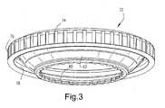
- FIGURE 3is a perspective view of an arc adjustment control ring from Figure 1;
- FIGURE 4is a perspective view of a drive ring taken from the sprinkler head illustrated in Figure 1;
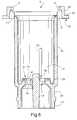
- FIGURE 5is a cross sectional view of a stem component taken from the sprinkler head illustrated in Figure 1;
- FIGURE 6is a top plan view of the stem shown in Figure 5;
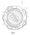
- FIGURE 7is a bottom plan view of the stem illustrated in Figure 5;
- FIGURE 8is a perspective view of the stem shown in Figure 5;
- FIGURE 9is a perspective view of a throttle control member taken from the sprinkler head in Figure 1;
- FIGURE 10is a plan view of the sprinkler head shown in Figure 1, but with parts removed for clarity;
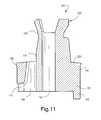
- FIGURE 11is a cross section of a stream deflector component taken from Figure 1;
- FIGURE 12is a top plan view of the stream deflector shown in Figure 11;
- FIGURE 13is a perspective view of the stream deflector shown in Figures 1 and 12;
- FIGURE 14is a bottom plan view of the stream deflector shown in Figure 13;
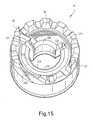
- FIGURE 15is a top perspective view of a nozzle as used in Figure 1;
- FIGURE 16is a bottom perspective view of the nozzle in Figure 15;
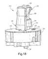
- FIGURE 18is a side elevation of the deflector component shown on Figure 17;
- FIGURE 19is a side elevation similar to Figure 18 but rotated 90° in a clockwise direction about a vertical axis;
- FIGURE 20is a plan view of the deflector shown in Figures 17-19;
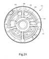
- FIGURE 21is a bottom plan view of the deflector shown in Figure 20;
- FIGURE 22is a top perspective view of the nozzles shown in Figures 15 and 16 in assembled relationship with the deflector shown in Figures 17-21;
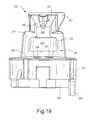
- FIGURE 23is a perspective view of the nozzle and deflector component similar to Figure 22, but rotated 90° in a counterclockwise direction;
- FIGURE 24is a top plan view of the deflector and nozzle in a fully assembled condition
- FIGURE 25is a cross section taken through line 25-25 in Figure 24;
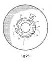
- FIGURE 26is a section taken along the line 26-26 in Figure 25;
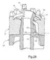
- FIGURE 27is a cross section taken through the line 27-27 in Figure 24;
- FIGURE 28is a perspective view of Figure 27;
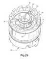
- FIGURE 29is a perspective view of the assembled nozzle and deflector components with the nozzle edge set to increase the wetted area by 30°;
- FIGURE 30is a schematic diagram illustrating a substantially rectangular wetted pattern area, with an option for extension along one side in accordance with the invention.
- the sprinkler head 10generally includes a base or housing 12 and a stem 14, with a conventional filter 16 attached to the lower end of the stem.
- the base 12is adapted to be threadably attached to a pressurized water source.
- a water distribution plate 18(or “rotor plate”) is mounted to the base 12, via a flow rate or throttle adjustment shaft 20 that extends between the plate 18 and the stem.
- a rotatable arc adjustment ring 22is secured to the top of the base 12.
- the rotor plate 18is mounted for rotation relative to the normally stationary shaft 20. Externally, the rotor plate 18 is formed with a series of generally radially oriented water distribution grooves 24.
- the grooves 24have lowermost entrance points that are preferably radially spaced from the shaft 20 in order to catch and distribute the arcuate (or annular) stream emanating from the nozzle 26.
- the groovesare also curved in a circumferential direction, causing the rotor plate to rotate about the shaft 20 when impinged upon by the stream.
- the rotational speed of the rotor plate 18may be slowed by a viscous dampening mechanism or "motor” (or “viscous retarder”) that includes a generally cup-shaped stator 28 fixed to the shaft 20.
- the statoris located in a chamber 30 defined by upper and lower bearings 32, 34 as well as the interior surface 36 of the hollow rotor plate 18.
- the chamber 30is filled or partially filled with a viscous fluid (preferably a silicone fluid) that exhibits viscous shear as the rotor plate 18 rotates relative to the fixed stator 28, significantly slowing the rotational speed of the rotor plate as compared to a rotational speed that would be achieved without viscous dampening.
- the viscous shearing actionis enhanced by the shape of the upper bearing 32, the lower portion of which fits within, but remains spaced from, the cup-shaped stator 28.
- Upper and lower annular seals 38, 40are mounted on the shaft 20 to prevent leakage of silicone fluid out of the chamber 30.
- a cap or retainer 42is press fit into the plate 18, with a seal ring 44 engaging an upper surface 46 of the upper bearing 32 to provide additional sealing of chamber 30.
- the base 12( Figures 1 and 2) includes a substantially cylindrical sleeve-like member 48 that is formed with an internally threaded inlet 50 by which the sprinkler head 10 may be attached to, for example, a conventional pop-up assembly or other sprinkler component.
- the inlet 50also includes a radially in-turned edge 52 that serves as an annular seat for a flexible seal 54.
- a substantial portion of the base 12is formed on its interior surface with a plurality (for example, 24) of circumferentially spaced, axially extending ribs or flutes 56.
- the upper end of the base 12is diametrically enlarged via a radial flange 58 that includes a radially outwardly and upwardly tapered surface 60 (Figure 2) that serves as a seat for a similarly tapered surface 62 ( Figure 1) on the arc adjustment ring 22 when the rotor plate 18 is in the retracted, inoperative position shown in Figure 1.
- Surface 60merges with a less sharply tapered rim 64 that has an undercut on its outer side to facilitate retention of the arc adjustment ring 22.
- a radial shoulder 66is adapted to engage an annular surface on the pop-up sprinkler body (not shown).
- the axially extending internal ribs or flutes 56 on the base 12are utilized to normally prevent rotation of the stem 14 relative to the base 12, but to permit such rotation upon the application of torque to the arc adjustment ring 22 over and above that required to adjust the pattern arc (also referred to herein as a "click adjust" feature, described in great detail below), in order to properly orient the pattern itself.
- Discontinuities or cut-outs 68, 70 in the rim 64 and flat 72 at the lower end of the base( Figure 2) are provided for orienting the base during assembly.
- the arc adjustment ring 22( Figures 1 and 3) includes an upper radially outturned rim 74 that is adapted to fit over the upper rim 64 of the base 12.
- Rim 74includes a depending skirt 76 that forms the outer diameter of the ring 22.
- the lower end of skirt 76is provided with a radially in-turned curl 78 engaged in the undercut below rim 64 such that the arc adjustment ring 22 is rotatable, but otherwise axially fixed relative to the base 12.
- the previously described tapered surface 62extends downwardly and inwardly to an annular row of radially inwardly facing (or horizontally projecting) gear teeth 80 ( Figure 3) that are used in the implementation of the arc adjustment capability as described further below.
- an arc adjustment actuator or drive ring 82is axially interposed between the arc adjustment ring 22 and the nozzle 26.
- the drive ring 82is formed with a first radially outwardly facing annular row of teeth 84 that are adjacent and below a conically-shaped upper rim 86.
- An annular undercut or groove 88 on the outer surface of the ringprovides a seat or shoulder 90 adapted to receive radially inwardly directed ribs 92 ( Figures 5, 6) on the stem 14.
- a second annular row of teeth 94( Figures 1 and 4) project downwardly from the lower end of the ring, spaced radially inwardly of the upper row of teeth 84.
- the upper horizontally-oriented row of teeth 84are adapted to mesh with the row of teeth 80 on the arc adjustment ring 22, but only when the rotor plate 18 and stem 14 are extended relative to the base.
- the lower vertically oriented row of teeth 94is adapted to always mesh with an upper row of teeth 96 on the nozzle 26 as described further below.
- the annular seat 88Just below the annular seat 88 are four, circumferentially equally spaced windows 98 ( Figure 4) that are located directly above corresponding ones of the teeth 96 on the nozzle. In other words, these windows 98 are, in fact, extensions of the spaces between the lower row of teeth 94.
- Two of the spaces or windows 98are adapted to receive two corresponding tabs 100 that extend upwardly from a pair of diametrically opposed teeth 96 on the nozzle 26 (see Figures 1, 4 and 15). These tabs 100 and windows or recesses 98 assure correct orientation of the drive ring 82 relative to the nozzle 26.
- a vertical rib (not shown) in the groove 88limits rotation of the ring 22 and nozzle 26 by engaging a selected edge of one of the radially inwardly directed ribs 92. As will be explained further below, this rib limits the rotation of the nozzle 26. Because the position of the limiting rib on the drive ring 82 is thus related to the nozzle orifice, it will be appreciated that the nozzle and drive ring must be properly oriented on assembly. Thus, for a nozzle with adjustability through a range of 90°-210°, the tabs 100 on the nozzle will seat in one pair of windows 98 while for a nozzle with a greater range, e.g., up to 270°, the tabs 100 will seat in the other pair of windows 98. This arrangement permits one drive ring configuration to be used with different nozzles.
- the flat 102 at the upper end of the drive ringalso facilitates automated assembly with the stem 14.
- FIGS 5-8illustrate the stem 14 in further detail.
- This stemis formed at its upper end with the above-mentioned pair of circumferentially spaced, radially inwardly directed, arcuate ribs 92.
- These ribsextend from an outer cylindrical wall 104 that extends downwardly to a radial flange 106 that provides a seating surface 108 for a coil spring 110.
- the flange 106includes a plurality of circumferentially spaced, laterally extending spring tabs 112 that are unequally spaced about the flange 106. Specifically, the spring tabs 112 and five associated rounded tips 114 are spaced to insure that each of the tips 114 will be seated between respective pairs of the twenty-four flutes 56 in the base 12.
- spring tabs 112With the flutes 16 that permits the sprinkling pattern to be reoriented even though the sprinkler head is attached to a fixed riser or other sprinkler component.
- the openings 116 adjacent the spring tabsallow the latter to flex as they rotate past the flutes 56 on the base during pattern reorientation, while allowing the stem per se to remain rigid.
- the stem 14is made up of a substantially cylindrical tubular portion 122, with a lower end having an annular groove 124 and a reduced diameter inlet portion 125.
- Groove 124is adapted to receive an upper end 126 of the filter 16 ( Figure 1) in snap-fit relationship.
- the tubular portion 122is formed with a pair of diametrically opposed, axially extending ribs 128, 130, extending radially inwardly from the interior surface 132 of the tubular portion 122.
- Ribs 128, 130terminate at their lower ends at a location adjacent and above the annular groove 124, where an upstanding, internal ring 134 joins to the internal surface 132 via an annular trough 136.
- the ring 134thus defines a constricted opening 138 within the reduced diameter inlet portion 125 of the stem.
- the ring 134is formed with a plurality of circumferentially spaced upstanding teeth 140, upper surfaces 142 of which provide a seat for the throttle control member 144. It will be appreciated that the spaces 146 between the teeth 140 permit water to pass through the inlet opening 138 and into the stem even when the throttle member is in its fully closed (or minimum flow) position, i.e., when seated on surfaces 142. This arrangement prevents stalling of the rotor plate under low flow conditions.
- part-annular flow restricting flange 148within the inlet opening 138 that serves to block some of the spaces 146 for proper throttling action on models with lower flow rates.
- a cross-web 150 and shortened cross piece 152( Figures 6-8), provide a seat for the throttle sleeve 154, with the raised center boss 156 extending into the hollow sleeve to maintain the shaft 20 and throttle sleeve 154 centered in the stem.
- the shaft 20extends downwardly through the nozzle 26 and through a stream deflector 164.
- the lower end of the shaft 20is provided with the externally threaded throttle sleeve 154 that is pressed onto (or otherwise secured to) the shaft.
- the sleeve 154preferably of metal construction, rests on the cross web 150 and shortened cross piece 152.
- the internally threaded throttle control member 144is threadably received on the axially fixed sleeve 154, such that rotation of the shaft 20 causes the throttle control member 144 to move toward or away from the seating surfaces 142 of the teeth 140, depending upon the direction of the rotation of the shaft.
- a slot 158 at the top of the shaft 20enables rotation of the shaft by a screw driver or similar tool.
- the throttle control member 144is formed with four, equally circumferentially spaced ears (two diametrically opposed pairs 160, 162) that, during normal operation, are located between the ribs 128, 130 as best seen in Figure 10. It will be appreciated that rotation of the shaft 20 will initially result in rotation of both the throttle sleeve 154 and the throttle control member 144 (in either direction), until the diametrically opposed ears 160 engage ribs 128, 130 to prevent further rotation of the throttle control member, causing it to move axially due to its threaded relationship with the sleeve 154. This assumes a normal application of torque via tool slot 158 to adjust the flow rate.
- the stream deflector 164is received within the stem 14 and cooperates with the nozzle 26 to define an arcuate water discharge orifice with an adjustable arcuate length.
- the stream deflector 164also includes an annular ring or skirt portion 166 by which the deflector is secured within the stem 14.
- an annular, radially outward flange 168seals against the interior surface 132 of the stem.
- a mating annular groove for receiving the flangemay be provided in surface 132.
- the skirt portion 166 of the ringis formed with a pair of notches 170, 172 ( Figure 13) that open along the bottom edge of the skirt and are adapted to receive the upper ends of the ribs 128, 130 on the interior surface 132 of the stem. This arrangement fixes the stream deflector 164 against rotation.
- a center hub 174lies at the center of the stream deflector 164 and is connected to the skirt portion 166 by a plurality of radial spokes 176, 178, 180 and 182 ( Figures 13, 14), all of which extend below the bottom edge 184 of the skirt portion 166.
- Each spoketerminates at its radially outward end in a respective cylindrical stub (186, 188, 190, 192) that lies on the bottom edge 184 of the skirt portion.
- Stubs 186, 188 and 190are flush with the bottom surfaces of the respective spokes 176, 178 and 180, while stub 192 extends beyond the bottom surface of spoke 182, serving as a further locator device during automated assembly.
- a bore 194extends through the stream deflector and receives the shaft 20 as shown in Figure 1.
- the stream deflector 164is designed for use with the nozzle 26 to produce an arcuate orifice that extends to a maximum of 210°, with adjustment within the range of 90°-210°.
- arcuate openings 196, 198are formed in the surface 200, on either side of the spoke 176.
- spoke 182effectively extends upwardly beyond the skirt portion, forming an upstanding tab 202, with a surface 204 ( Figure 12) that forms the "fixed" edge of the nozzle discharge orifice.
- Figures 15 and 16illustrate in greater detail the nozzle 26 that is supported on the stream deflector 164 (within the stem 14) for rotation relative to the stream deflector.
- the nozzle 26is a generally cylindrical member with a centered, axial opening that the deflector 164 and the shaft 20 pass through, with an arcuate surface 206 engaged by the hub 174 of the deflector.
- the nozzle 26has an inlet end 208 and an outlet formed by an arcuate edge 210 with a rounded undercut 212 below the edge and a radially outwardly tapering surface 214 above the edge.
- Arcuate edge 210is spaced radially outwardly of deflector surface 216 to thereby define the width of the arcuate discharge orifice.
- the edge 210extends approximately 250° from a first vertical surface 218 of an upstanding tab 220, to an edge 222 of a radial opening or notch 224.
- Vertical surface 218thus comprises the "adjustable edge" of the nozzle orifice.
- Surfaces 204 (of the deflector) and 218 (of the nozzle)may also be referred to as defining "limit positions.”
- the tab 220also seals against an hourglass-shaped (or cone-shaped) portion 226 ( Figure 11) of the deflector 164 that extends in either direction from surface 216. (The manner in which the nozzle 26 interacts with the stream deflector 164 remains as described in greater detail in the '905 and '332 patents).
- the nozzle 26is also formed with a flat 230 ( Figure 15) that cuts across a portion of the teeth 96, and is used to facilitate auto-assembly with the stem 14.
- a gear drive(or gear train) is established between the arc adjustment ring 22 and the nozzle 26 by reason of the engagement of teeth 80 on ring 22 with teeth 84 on the drive ring 82, and teeth 94 on the ring 82 with teeth 96 on the nozzle.
- rotation of the arc adjustment ring 22will rotate the nozzle 26, relative to the deflector 164 to alter the arcuate length of the water discharge orifice between 90° and 210°.
- the stream deflector 164 and its integral fixed edge 204may be rotated to re-orient one edge of the pattern by simply turning the arc adjustment ring 22 beyond its normal range.
- the ring 22may be rotated to its most restricted position (with a 90° opening).
- the drive ring 82, stem 14, stream deflector 164 and nozzle 26(along with other of the internal components) will rotate together until the fixed edge 204 is in the desired position.
- the ring 22can then be rotated in an opposite direction to achieve the desired arc of coverage between 90° and 210°.
- the arc adjustment ring 22may be rotated to the fully open position (210°), and then rotated beyond that position through the application of additional torque to reorient the fixed edge 204.
- the arc adjustment ring 22may then be rotated in the opposite direction to shorten the arc to any position between 90°-210°.
- a modified stream deflector component 232 in accordance with an exemplary embodiment of this inventionis able to produce, in combination with nozzle 26, a substantially rectangular wetted pattern area.
- the deflectoris generally similar to the deflector 164 and only the modifications necessary to produce the desired pattern area will be discussed in detail below.
- Other minor changes in shapeare related to ease of manufacture, as dictated by plastic molding or metal shaping processes.
- a pair of upstanding ribs 234, 236have been added to the center hub 238 above the slightly convex, or substantially horizontal wall surface 240 that otherwise closes the upper end of the annular ring or skirt 242.
- One rib 236lies adjacent and parallel to the upstanding tab 244 (similar to tab 202).
- the circumferential space between the upstanding tab 244 (similar to tab 202) and rib 236accommodates a first shortened arcuate slot 246 ( Figure 20) formed in the surface 240.
- the second rib 234is circumferentially-spaced about the center hub 238 at a location such that ribs 234 and 236 lie substantially in the same vertical plane, best seen in Figure 20.
- a second substantially arcuate slot 248 formed in surface 240lies adjacent rib 234.
- the second substantially arcuate slotspans an angle of about 35°, as compared to the first substantially arcuate slot which spans an angle of about 15°.
- 246, 248have respective side edges 247, 249 that are defined by ribs 236, 234 that are not radial center lines, as best seen in Figure 20.
- a pair of restrictive flow ports 250, 252are also formed in the wall surface 240, substantially circumferentially centered between ribs 234 and 236 (and hence between slots 246 and 248).
- a substantially V-shaped boss 254is formed on the outwardly tapering surface 256 of the cone-shaped portion of the center hub 238, circumferentially centered between the ports 250, 252.
- the lower edge 258 of the bossis centered between the ports 250, 252, while the upper edge of the boss substantially spans the mid-points of the ports, From top-to-bottom, the boss 254 decreases in thickness, thus projecting a rounded wedge-shape from the tapered surface 256.
- Figure 21shows the underside of the deflector 232, and the location of substantially arcuate slots 246, 248 and restrictive flow ports 250, 252 relative to the spokes 260, 262, 264 and 266 that connect the center hub 238 to the annular ring or skirt 242. More specifically, the first substantially arcuate slot 246 lies adjacent spoke 260 while the second substantially arcuate slot 248 lies adjacent spoke 262. Note that the vertical tab 244 is essentially an extension of spoke 260. Ports 250, 252 lie on either side of spoke 266. A downwardly extended portion 267 of spoke 260 serves as an assembly locator.
- Figures 22 to 29illustrate the modified deflector 232 in assembled relationship with the nozzle 26.
- this nozzleis one that is otherwise used to obtain an arcuate pattern of between 90° and 210°.
- the nozzle orifice created by the tab 244 and edge 218 of the nozzleis separated into three discrete arcuate portions that defines sections A, B and C of the pattern P (see Figure 30).
- the orifice sectionswill also be designated A, B and C for ease of understanding.
- the orifice section Ais defined by the tab 244, rib 236 and part of arcuate nozzle edge 210 along with surface 256 of the deflector, and water is supplied unrestricted to this section via the substantially arcuate slot 246.
- the orifice section Bis defined by rib 234 and vertical adjustment edge 218 of the nozzle, part of the arcuate nozzle edge 210 and surface 256 of the deflector. Water is also supplied unrestricted to this section via substantially arcuate slot 248.
- the streams emitted from orifice sections A and Bare full-throw streams that are confined to narrow arcs, covering the lateral ends or sides of the pattern.
- the larger arcuate orifice section Cis defined by the ribs 234, 236 and a portion of the arcuate nozzle edge 210 and surface 256 of the deflector and is supplied with water subject to restriction via the ports 250,252.
- section Bcan be enlarged up to about 30° as illustrated in Figures 29 and 30.
- the relative rotational movement of the lower nozzle edge 270 across the ports 250, 252may reorient any such particle P so that it is flushed through the device, i.e., passed through the nozzle orifice in section C.
- the patternmay be fixed to produce a set rectangular pattern, with no relative rotation possible between the deflector and nozzle.
- the size of the patternmay, of course, be reduced by throttle adjustment as explained above.
Landscapes
- Nozzles (AREA)
- Catching Or Destruction (AREA)
- Special Spraying Apparatus (AREA)
Abstract
Description
- This invention relates to sprinklers and, specifically, to a sprinkler that incorporates an adjustable flow rate feature in combination with a specialized nozzle and stream deflector for creating a substantially rectangular water distribution pattern.
- It is known to utilize interchangeable arc or other shaped nozzles in sprinklers in order to modify the pattern wetted by the discharge stream, while maintaining a constant flow or precipitation rate in the wetted areas. Typically, these nozzles comprise orifice plates which have a central hole for receiving a shaft that supports the distributor above the nozzle. The orifice itself is generally radially outwardly spaced from the shaft hole in the orifice plate. Representative examples of this type of construction are found in
U.S. Patent Nos. 4,967,961 ;4,932,590 ;4,842,201 ;4,471,908 ; and3,131,867 . Other arc adjustment techniques are described inU.S. Patent Nos. 5,556,036 ;5,148,990 ;5,031,840 ;4,579,285 ; and4,154,404 . It is also known to incorporate adjustable flow rate arrangements in sprinklers, within the context of substantially constant water pressure. For example, seeU.S. Patent Nos. 5,762,270 ;4,898,332 ; and4,119,275 . Such arc adjustment and flow rate adjustment features are often incorporated into pop-up sprinklers. Examples of pop-up sprinklers are found inU.S. Patent Nos. 5,288,022 ;5,058,806 ;4,834,289 ;4,815,662 ; and4,790,481 . - Commonly owned
U.S. Patent Nos. 6,651,905 and6,736,332 (both of which are incorporated in their entirety herein by reference) disclose sprinkler heads designed especially (but not exclusively) for use with pop-up type sprinklers configurations, and that provide within limits, essentially infinite arc adjustment and throw radius adjustment features, and at the same time, constant precipitation rates and good uniformity. These sprinklers also minimize suckback plugging of the nozzle; permit active cleaning of the nozzle, and minimize potential damage to critical internal components when, for example, impacted during use. - The sprinkler heads in the '905 and '332 patents generally include a nozzle and a rotary water distribution plate (or rotor plate) mounted on a shaft so as to be axially spaced from the nozzle. The rotor plate is formed with a plurality of curved, generally radial grooves that cause the rotor plate to rotate when impinged upon by a hollow, generally cone-shaped stream emitted from the nozzle. The rotor plate may incorporate a viscous damping mechanism to slow its rate of rotation.
- In the pop-up embodiments, the nozzle and associated stream deflector are supported within a hollow stem which, in turn, is supported within a cylindrical base. A coil spring is located axially between a flange at the upper end of the stem and an arc adjustment ring at the upper end of the base. This coil spring biases the rotor plate, shaft, nozzle, deflector and stem to a retracted position relative to the base.
- The shaft on which the rotor plate is mounted extends downwardly into and through the deflector, and is provided with an externally threaded metal sleeve fixed to the lower end of the shaft. A throttle member is threadably mounted on the fixed sleeve, so that rotation of the shaft will result in the throttle member moving axially upwardly or downwardly on the shaft, depending on the direction of rotation of the shaft, toward or away from a flow-restriction stop formed near the lower end of the stem. In this way, flow rate to the nozzle, and hence throw radius, can be adjusted as desired. A "slip clutch" mechanism is also provided to protect the throttle assembly in the event of over-rotation of the shaft. Preferably, the arrangement is such that the flow cannot be completely shut off. In other words, even in a position where the throttle member is moved to its maximum restrictive position, enough water is permitted to flow through the base to the nozzle so that the rotor plate continues to rotate, albeit at a slower speed. This preferred configuration is intended to prevent stalling, a condition where the rotor plate ceases rotation as water pressure drops. The throw radius adjustment is effected by rotation of the shaft by a suitable tool engageable with an end of the shaft that is externally accessible to the user. Aside from the flow rate or throw radius adjustment function, the shaft is otherwise rotationally stationary during normal operation, i.e., the rotor plate rotates about the shaft.
- In accordance with the '332 patent, the throttle member may be constructed of a suitable urethane rubber and preferably a polyurethane thermoplastic elastomer. Using this material, the interior surface of the throttle member may be left smooth when manufactured, but will resiliently self-tap when engaged by the externally threaded metal sleeve fixed to the lower end of the shaft. This arrangement is particularly advantageous in that, in the event the shaft is over-rotated, the elastomeric throttle member will simply slip over the thread on the metal sleeve, thus creating an effective "slip clutch" that prevents damage to the stem assembly.
- In the '332 and '905 patents, the nozzle is rotatably mounted within the base, and cooperates with a stream deflector mounted on the shaft to define an arcuate water discharge orifice. The nozzle is operatively connected through a drive mechanism to the arc adjustment ring mounted on the top of the base, and externally accessible to the user. Thus, the user may rotate the arc adjustment ring to lengthen or shorten the arcuate length of the discharge orifice. It is disclosed that a pair of nozzle/deflector combinations may be employed to provide adjustable arcs between 90° and 210°, and between 210° and 270°. In accordance with another embodiment, the nozzle and deflector are further modified to provide a 360° or full circle pattern.
- The arc adjustment feature can be utilized in a pop-up sprinkler only when the rotor plate is extended relative to the base. In other words, components of the drive mechanism are fully engaged only when the nozzle, deflector and stem move upwardly with the rotor plate to engage complementary drive components on the arc adjustment ring. This arrangement prevents accidental arc adjustment when the sprinkler is not in use, e.g., through contact with a lawn mower, weed trimmer or the like. In addition, the arc adjustment ring is configured to permit re-orientation of the sprinkler pattern after the sprinkler is secured to, for example, a fixed, non-rotatable stem or riser in a pop-up assembly.
- When used in a pop-up type sprinkler, the sprinklers disclosed in the '332 and '905 patents are extended by a two-stage pop-up mechanism. First, the extendable tube of the pop-up assembly will extend as water under pressure is introduced into the assembly. After the tube extends out of the fixed riser, the rotor plate, nozzle, deflector and stem extend further away from the base at the distal end of the extendable tube so that water emitted from the nozzle can be distributed radially by the rotor plate. This two-stage action is reversed when the flow of water is shut off, so that the rotor plate is in a retracted position that prevents any foreign matter from entering into the nozzle area before the extendable tube of the pop-up assembly is retracted.
- In accordance with this invention, the stream deflector component of the deflector/nozzle assembly as disclosed in the '332 and '905 patents is modified to produce a wetted area or pattern that is long and narrow (i.e., substantially rectangular) rather than the traditional circular or part-circular patterns).
- It is understood that the nozzle orifice (where the water stream emits to atmosphere) as disclosed in the '332 and '905 patents, is in the form of an arcuate slot defined by cooperating geometry of the deflector and nozzle components. By modifying the deflector, as described herein, it is possible to shape the water stream upstream of the water distribution or rotor plate such that it will interact with the latter to achieve the desired rectangular-shaped wetted pattern area.
- More specifically, modification of the stream deflector helps to create a nozzle orifice that is separated into three sections, each section designed to water a different portion of the desired rectangular pattern area. Two of the sections (i.e., two side sections at opposite ends of the rectangular pattern) are formed in part by two normal, arcuate slots, but of shortened arcuate length, provided in a horizontal wall surface of the deflector, with unrestricted water passages supplying water to these side slots, and with unmodified, cone-shaped surfaces of the stream deflector creating, in combination with the nozzle, a normal hollow, cone-shaped full-energy stream in these two side sections. A third arcuate slot, located between the two side slots, is supplied with water via restrictive ports upstream of the orifice, in the same horizontal wall surface of the deflector, that reduce energy in the stream. In addition, the cone-shaped surface of the stream deflector, downstream of the third arcuate slot, is modified to include a projecting boss that, in combination with the nozzle, re-shapes the low-energy stream for interaction with the rotary distributor to properly fill in the middle area or section between the first two side sections. In this regard, the deflector boss is shaped to create a stream that throws only a very short distance in front of the sprinkler, gradually increasing in distance of throw on both sides of this frontal area.
- Another feature of this modified design allows for some adjustability along one side edge of the substantially rectangular-shaped wetted pattern area that, in effect, enlarges one end of the otherwise rectangular pattern.
- Still another feature of the modified design is that the throttle can be used to reduce the size of the area watered while the length and width of the pattern is kept generally proportional.
- In a related embodiment, it is possible to provide complimentary "end units" at opposite ends of the rectangular pattern area by blocking one or the other of the two side section orifices, and the adjacent half of the middle section.
- Accordingly, in one aspect, the invention relates to a rotary sprinkler comprising a sprinkler body supporting a nozzle body and a water distribution plate supported on a shaft downstream of the nozzle body, the water distribution plate provided with a plurality of grooves shaped to redirect a stream emitted from the nozzle body and to cause the water distribution plate to rotate when struck by the stream, the nozzle body having an arcuate edge partially defining plural discharge orifices; a stream deflector supported within the sprinkler body and surrounded by the nozzle body; wherein the stream deflector is configured to cooperate with the arcuate edge to produce a substantially rectangular pattern.
- In another aspect, the invention relates to a rotary sprinkler comprising a sprinkler body supporting a nozzle body and a water distribution plate supported on a shaft downstream of the nozzle body, the water distribution plate provided with a plurality of grooves shaped to redirect a stream emitted from the nozzle body and to cause the water distribution plate to rotate when struck by the stream, the nozzle body having an arcuate edge partially defining plural discharge orifices; and means for shaping a stream emitted from the nozzle body to produce a rectangular pattern.
- In yet another aspect, the invention relates to a deflector for a sprinkler having a nozzle body formed with an arcuate edge that partially defines plural discharge orifices, the deflector comprising a center hub extending upwardly through an annular ring closed at an upper end thereof by a substantially horizontal surface, the center hub having an arcuate stream-engaging surface at an upper end thereof adapted to cooperate with the arcuate edge of the nozzle to form the plural discharge orifices; a pair of vertical, arcuately spaced ribs on the center hub extending upwardly from the horizontal surface for partially defining a first of the plural discharge orifices; an upstanding tab proximate one of the pair of ribs such that the one of the pair of ribs and the upstanding tab partially define a second of the plural discharge orifices, and wherein the outer of the pair of ribs partially defines a third of the plural discharge orifices; a first substantially arcuate slot formed in the horizontal surface between the one of the pair of ribs and the upstanding tab, and a second substantially arcuate slot formed in the horizontal surface adjacent the other of the pair of tabs; and at least one flow port formed in the horizontal surface between the pair of ribs..
- In still another aspect, the invention relates to a rotary sprinkler comprising a sprinkler body supporting a nozzle body and a water distribution plate supported on a shaft downstream of the nozzle body, the water distribution plate provided with a plurality of grooves shaped to redirect a stream emitted from the nozzle body and to cause the water distribution plate to rotate when struck by the stream, the nozzle body having an edge partially defining plural discharge orifices; a stream deflector supported within the sprinkler body and surrounded by the nozzle body; wherein the stream deflector is configured to cooperate with the edge to produce a substantially rectangular pattern, the deflector provided at least one port for restricting flow to one of the plural discharge orifices.
- The invention will now be described in detail in connection with the drawings identified below.
- FIGURE 1 is a cross sectional view of a sprinkler head in accordance with an embodiment of the invention;
- FIGURE 2 is a perspective view of a base element of the sprinkler head in Figure 1;
- FIGURE 3 is a perspective view of an arc adjustment control ring from Figure 1;
- FIGURE 4 is a perspective view of a drive ring taken from the sprinkler head illustrated in Figure 1;
- FIGURE 5 is a cross sectional view of a stem component taken from the sprinkler head illustrated in Figure 1;
- FIGURE 6 is a top plan view of the stem shown in Figure 5;
- FIGURE 7 is a bottom plan view of the stem illustrated in Figure 5;
- FIGURE 8 is a perspective view of the stem shown in Figure 5;
- FIGURE 9 is a perspective view of a throttle control member taken from the sprinkler head in Figure 1;
- FIGURE 10 is a plan view of the sprinkler head shown in Figure 1, but with parts removed for clarity;
- FIGURE 11 is a cross section of a stream deflector component taken from Figure 1;
- FIGURE 12 is a top plan view of the stream deflector shown in Figure 11;
- FIGURE 13 is a perspective view of the stream deflector shown in Figures 1 and 12;
- FIGURE 14 is a bottom plan view of the stream deflector shown in Figure 13;
- FIGURE 15 is a top perspective view of a nozzle as used in Figure 1;
- FIGURE 16 is a bottom perspective view of the nozzle in Figure 15;
- FIGURE 17 of the deflector component in accordance with another exemplary embodiment of the invention;
- FIGURE 18 is a side elevation of the deflector component shown on Figure 17;
- FIGURE 19 is a side elevation similar to Figure 18 but rotated 90° in a clockwise direction about a vertical axis;
- FIGURE 20 is a plan view of the deflector shown in Figures 17-19;
- FIGURE 21 is a bottom plan view of the deflector shown in Figure 20;
- FIGURE 22 is a top perspective view of the nozzles shown in Figures 15 and 16 in assembled relationship with the deflector shown in Figures 17-21;
- FIGURE 23 is a perspective view of the nozzle and deflector component similar to Figure 22, but rotated 90° in a counterclockwise direction;
- FIGURE 24 is a top plan view of the deflector and nozzle in a fully assembled condition;
- FIGURE 25 is a cross section taken through line 25-25 in Figure 24;
- FIGURE 26 is a section taken along the line 26-26 in Figure 25;
- FIGURE 27 is a cross section taken through the line 27-27 in Figure 24;
- FIGURE 28 is a perspective view of Figure 27;
- FIGURE 29 is a perspective view of the assembled nozzle and deflector components with the nozzle edge set to increase the wetted area by 30°; and
- FIGURE 30 is a schematic diagram illustrating a substantially rectangular wetted pattern area, with an option for extension along one side in accordance with the invention.
- With reference initially to Figure 1-16, the
sprinkler head 10 generally includes a base orhousing 12 and astem 14, with aconventional filter 16 attached to the lower end of the stem. Thebase 12 is adapted to be threadably attached to a pressurized water source. A water distribution plate 18 (or "rotor plate") is mounted to thebase 12, via a flow rate orthrottle adjustment shaft 20 that extends between theplate 18 and the stem. A rotatablearc adjustment ring 22 is secured to the top of thebase 12. - The
rotor plate 18 is mounted for rotation relative to the normallystationary shaft 20. Externally, therotor plate 18 is formed with a series of generally radially orientedwater distribution grooves 24. Thegrooves 24 have lowermost entrance points that are preferably radially spaced from theshaft 20 in order to catch and distribute the arcuate (or annular) stream emanating from thenozzle 26. The grooves are also curved in a circumferential direction, causing the rotor plate to rotate about theshaft 20 when impinged upon by the stream. - The rotational speed of the
rotor plate 18 may be slowed by a viscous dampening mechanism or "motor" (or "viscous retarder") that includes a generally cup-shapedstator 28 fixed to theshaft 20. The stator is located in achamber 30 defined by upper andlower bearings interior surface 36 of thehollow rotor plate 18. Thechamber 30 is filled or partially filled with a viscous fluid (preferably a silicone fluid) that exhibits viscous shear as therotor plate 18 rotates relative to the fixedstator 28, significantly slowing the rotational speed of the rotor plate as compared to a rotational speed that would be achieved without viscous dampening. The viscous shearing action is enhanced by the shape of theupper bearing 32, the lower portion of which fits within, but remains spaced from, the cup-shapedstator 28. - Upper and lower
annular seals shaft 20 to prevent leakage of silicone fluid out of thechamber 30. A cap orretainer 42 is press fit into theplate 18, with aseal ring 44 engaging anupper surface 46 of theupper bearing 32 to provide additional sealing ofchamber 30. - The base 12 (Figures 1 and 2) includes a substantially cylindrical sleeve-
like member 48 that is formed with an internally threadedinlet 50 by which thesprinkler head 10 may be attached to, for example, a conventional pop-up assembly or other sprinkler component. Theinlet 50 also includes a radially in-turnededge 52 that serves as an annular seat for aflexible seal 54. A substantial portion of thebase 12 is formed on its interior surface with a plurality (for example, 24) of circumferentially spaced, axially extending ribs or flutes 56. The upper end of thebase 12 is diametrically enlarged via aradial flange 58 that includes a radially outwardly and upwardly tapered surface 60 (Figure 2) that serves as a seat for a similarly tapered surface 62 (Figure 1) on thearc adjustment ring 22 when therotor plate 18 is in the retracted, inoperative position shown in Figure 1. Surface 60 merges with a less sharply taperedrim 64 that has an undercut on its outer side to facilitate retention of thearc adjustment ring 22. Aradial shoulder 66 is adapted to engage an annular surface on the pop-up sprinkler body (not shown). As explained further below, the axially extending internal ribs or flutes 56 on thebase 12 are utilized to normally prevent rotation of thestem 14 relative to thebase 12, but to permit such rotation upon the application of torque to thearc adjustment ring 22 over and above that required to adjust the pattern arc (also referred to herein as a "click adjust" feature, described in great detail below), in order to properly orient the pattern itself. Discontinuities or cut-outs rim 64 and flat 72 at the lower end of the base (Figure 2) are provided for orienting the base during assembly.- The arc adjustment ring 22 (Figures 1 and 3) includes an upper radially outturned
rim 74 that is adapted to fit over theupper rim 64 of thebase 12.Rim 74 includes a dependingskirt 76 that forms the outer diameter of thering 22. The lower end ofskirt 76 is provided with a radially in-turnedcurl 78 engaged in the undercut belowrim 64 such that thearc adjustment ring 22 is rotatable, but otherwise axially fixed relative to thebase 12. The previously described taperedsurface 62 extends downwardly and inwardly to an annular row of radially inwardly facing (or horizontally projecting) gear teeth 80 (Figure 3) that are used in the implementation of the arc adjustment capability as described further below. - With reference now to Figure 4, and with continuing reference to Figure 1, an arc adjustment actuator or drive
ring 82 is axially interposed between thearc adjustment ring 22 and thenozzle 26. Thedrive ring 82 is formed with a first radially outwardly facing annular row ofteeth 84 that are adjacent and below a conically-shapedupper rim 86. An annular undercut or groove 88 on the outer surface of the ring provides a seat orshoulder 90 adapted to receive radially inwardly directed ribs 92 (Figures 5, 6) on thestem 14. A second annular row of teeth 94 (Figures 1 and 4) project downwardly from the lower end of the ring, spaced radially inwardly of the upper row ofteeth 84. - The upper horizontally-oriented row of
teeth 84 are adapted to mesh with the row ofteeth 80 on thearc adjustment ring 22, but only when therotor plate 18 and stem 14 are extended relative to the base. The lower vertically oriented row ofteeth 94 is adapted to always mesh with an upper row ofteeth 96 on thenozzle 26 as described further below. Just below theannular seat 88 are four, circumferentially equally spaced windows 98 (Figure 4) that are located directly above corresponding ones of theteeth 96 on the nozzle. In other words, thesewindows 98 are, in fact, extensions of the spaces between the lower row ofteeth 94. Two of the spaces orwindows 98 are adapted to receive twocorresponding tabs 100 that extend upwardly from a pair of diametricallyopposed teeth 96 on the nozzle 26 (see Figures 1, 4 and 15). Thesetabs 100 and windows or recesses 98 assure correct orientation of thedrive ring 82 relative to thenozzle 26. - A vertical rib (not shown) in the
groove 88 limits rotation of thering 22 andnozzle 26 by engaging a selected edge of one of the radially inwardly directedribs 92. As will be explained further below, this rib limits the rotation of thenozzle 26. Because the position of the limiting rib on thedrive ring 82 is thus related to the nozzle orifice, it will be appreciated that the nozzle and drive ring must be properly oriented on assembly. Thus, for a nozzle with adjustability through a range of 90°-210°, thetabs 100 on the nozzle will seat in one pair ofwindows 98 while for a nozzle with a greater range, e.g., up to 270°, thetabs 100 will seat in the other pair ofwindows 98. This arrangement permits one drive ring configuration to be used with different nozzles. The flat 102 at the upper end of the drive ring (see Fig. 4) also facilitates automated assembly with thestem 14. - Figures 5-8 illustrate the
stem 14 in further detail. This stem is formed at its upper end with the above-mentioned pair of circumferentially spaced, radially inwardly directed,arcuate ribs 92. These ribs extend from an outercylindrical wall 104 that extends downwardly to aradial flange 106 that provides aseating surface 108 for acoil spring 110. Theflange 106 includes a plurality of circumferentially spaced, laterally extendingspring tabs 112 that are unequally spaced about theflange 106. Specifically, thespring tabs 112 and five associatedrounded tips 114 are spaced to insure that each of thetips 114 will be seated between respective pairs of the twenty-fourflutes 56 in thebase 12. As further described below, it is the interaction ofspring tabs 112 with theflutes 16 that permits the sprinkling pattern to be reoriented even though the sprinkler head is attached to a fixed riser or other sprinkler component. In this regard, theopenings 116 adjacent the spring tabs allow the latter to flex as they rotate past theflutes 56 on the base during pattern reorientation, while allowing the stem per se to remain rigid. - In order to form the arcuate, radially inwardly directed
ribs 92,slots corresponding flange 106, thus permitting access by forming tools during manufacture. - Below
flange 106, thestem 14 is made up of a substantially cylindricaltubular portion 122, with a lower end having anannular groove 124 and a reduceddiameter inlet portion 125.Groove 124 is adapted to receive anupper end 126 of the filter 16 (Figure 1) in snap-fit relationship. Interiorly, thetubular portion 122 is formed with a pair of diametrically opposed, axially extendingribs interior surface 132 of thetubular portion 122. Ribs annular groove 124, where an upstanding,internal ring 134 joins to theinternal surface 132 via anannular trough 136. Thering 134 thus defines aconstricted opening 138 within the reduceddiameter inlet portion 125 of the stem. Thering 134 is formed with a plurality of circumferentially spacedupstanding teeth 140,upper surfaces 142 of which provide a seat for thethrottle control member 144. It will be appreciated that thespaces 146 between theteeth 140 permit water to pass through theinlet opening 138 and into the stem even when the throttle member is in its fully closed (or minimum flow) position, i.e., when seated onsurfaces 142. This arrangement prevents stalling of the rotor plate under low flow conditions.- Note also the part-annular flow restricting flange 148 (Figures 6, 8) within the inlet opening 138 that serves to block some of the
spaces 146 for proper throttling action on models with lower flow rates. - A cross-web 150 and shortened cross piece 152 (Figures 6-8), provide a seat for the
throttle sleeve 154, with the raisedcenter boss 156 extending into the hollow sleeve to maintain theshaft 20 andthrottle sleeve 154 centered in the stem. - As best seen in Figure 1, the
shaft 20 extends downwardly through thenozzle 26 and through astream deflector 164. The lower end of theshaft 20 is provided with the externally threadedthrottle sleeve 154 that is pressed onto (or otherwise secured to) the shaft. Thesleeve 154, preferably of metal construction, rests on thecross web 150 and shortenedcross piece 152. The internally threadedthrottle control member 144 is threadably received on the axially fixedsleeve 154, such that rotation of theshaft 20 causes thethrottle control member 144 to move toward or away from the seating surfaces 142 of theteeth 140, depending upon the direction of the rotation of the shaft. Aslot 158 at the top of theshaft 20 enables rotation of the shaft by a screw driver or similar tool. - The manner in which the
throttle control member 144 moves toward or away from the seat (142) on rotation of theshaft 20 viatool slot 158 remains as described in the '332 and '905 patents. Note again thatshaft 20 is stationary during normal operation, and is rotatable only to adjust the flow rate. - The
throttle control member 144, as best seen in Figure 9, is formed with four, equally circumferentially spaced ears (two diametricallyopposed pairs 160, 162) that, during normal operation, are located between theribs shaft 20 will initially result in rotation of both thethrottle sleeve 154 and the throttle control member 144 (in either direction), until the diametricallyopposed ears 160 engageribs sleeve 154. This assumes a normal application of torque viatool slot 158 to adjust the flow rate. - It will be appreciated, however, that if excess torque is applied after the
throttle control member 144 is seated onsurface 142 of theteeth 140, theflexible ears 160 will permit thethrottle control member 144 to rotate past theribs ears 162 engage theribs - It will be understood that over-rotation in the throttle opening direction is handled in a similar manner, as permitted by the axial length of the
ribs - Turning now to Figures 11-14, and with the continuing reference to Figure 1, the
stream deflector 164 is received within thestem 14 and cooperates with thenozzle 26 to define an arcuate water discharge orifice with an adjustable arcuate length. Thestream deflector 164 also includes an annular ring orskirt portion 166 by which the deflector is secured within thestem 14. Specifically, an annular, radially outward flange 168 seals against theinterior surface 132 of the stem. A mating annular groove for receiving the flange may be provided insurface 132. Theskirt portion 166 of the ring is formed with a pair ofnotches 170, 172 (Figure 13) that open along the bottom edge of the skirt and are adapted to receive the upper ends of theribs interior surface 132 of the stem. This arrangement fixes thestream deflector 164 against rotation. - A
center hub 174 lies at the center of thestream deflector 164 and is connected to theskirt portion 166 by a plurality ofradial spokes bottom edge 184 of theskirt portion 166. Each spoke terminates at its radially outward end in a respective cylindrical stub (186, 188, 190, 192) that lies on thebottom edge 184 of the skirt portion. Stubs respective spokes stub 192 extends beyond the bottom surface ofspoke 182, serving as a further locator device during automated assembly. Abore 194 extends through the stream deflector and receives theshaft 20 as shown in Figure 1.- The
stream deflector 164 is designed for use with thenozzle 26 to produce an arcuate orifice that extends to a maximum of 210°, with adjustment within the range of 90°-210°. To this end,arcuate openings 196, 198 (Figures 11 and 12) are formed in thesurface 200, on either side of thespoke 176. Note that spoke 182 effectively extends upwardly beyond the skirt portion, forming anupstanding tab 202, with a surface 204 (Figure 12) that forms the "fixed" edge of the nozzle discharge orifice. - Figures 15 and 16 illustrate in greater detail the
nozzle 26 that is supported on the stream deflector 164 (within the stem 14) for rotation relative to the stream deflector. Thenozzle 26 is a generally cylindrical member with a centered, axial opening that thedeflector 164 and theshaft 20 pass through, with anarcuate surface 206 engaged by thehub 174 of the deflector. Thenozzle 26 has aninlet end 208 and an outlet formed by anarcuate edge 210 with a rounded undercut 212 below the edge and a radially outwardly taperingsurface 214 above the edge.Arcuate edge 210 is spaced radially outwardly ofdeflector surface 216 to thereby define the width of the arcuate discharge orifice. Circumferentially, theedge 210 extends approximately 250° from a firstvertical surface 218 of anupstanding tab 220, to anedge 222 of a radial opening or notch 224.Vertical surface 218 thus comprises the "adjustable edge" of the nozzle orifice. Surfaces 204 (of the deflector) and 218 (of the nozzle) may also be referred to as defining "limit positions." Note that thetab 220 also seals against an hourglass-shaped (or cone-shaped) portion 226 (Figure 11) of thedeflector 164 that extends in either direction fromsurface 216. (The manner in which thenozzle 26 interacts with thestream deflector 164 remains as described in greater detail in the '905 and '332 patents). Thenozzle 26 is also formed with a flat 230 (Figure 15) that cuts across a portion of theteeth 96, and is used to facilitate auto-assembly with thestem 14. - Also as described above, when the
nozzle 26 is in place, and with therotor plate 18, stem 14 anddeflector 164 extended relative to thebase 12, a gear drive (or gear train) is established between thearc adjustment ring 22 and thenozzle 26 by reason of the engagement ofteeth 80 onring 22 withteeth 84 on thedrive ring 82, andteeth 94 on thering 82 withteeth 96 on the nozzle. Thus, rotation of thearc adjustment ring 22 will rotate thenozzle 26, relative to thedeflector 164 to alter the arcuate length of the water discharge orifice between 90° and 210°. - The
stream deflector 164 and its integral fixededge 204 may be rotated to re-orient one edge of the pattern by simply turning thearc adjustment ring 22 beyond its normal range. In other words, thering 22 may be rotated to its most restricted position (with a 90° opening). Then, through the application of additional torque on thering 22, thedrive ring 82,stem 14,stream deflector 164 and nozzle 26 (along with other of the internal components) will rotate together until the fixededge 204 is in the desired position. Thering 22 can then be rotated in an opposite direction to achieve the desired arc of coverage between 90° and 210°. Conversely, thearc adjustment ring 22 may be rotated to the fully open position (210°), and then rotated beyond that position through the application of additional torque to reorient the fixededge 204. Thearc adjustment ring 22 may then be rotated in the opposite direction to shorten the arc to any position between 90°-210°. - Turning now to Figures 17 to 21, a modified
stream deflector component 232 in accordance with an exemplary embodiment of this invention is able to produce, in combination withnozzle 26, a substantially rectangular wetted pattern area. The deflector is generally similar to thedeflector 164 and only the modifications necessary to produce the desired pattern area will be discussed in detail below. Other minor changes in shape (as compared to deflector 164) are related to ease of manufacture, as dictated by plastic molding or metal shaping processes. - In the modified deflector, a pair of
upstanding ribs center hub 238 above the slightly convex, or substantiallyhorizontal wall surface 240 that otherwise closes the upper end of the annular ring orskirt 242. Onerib 236 lies adjacent and parallel to the upstanding tab 244 (similar to tab 202). The circumferential space between the upstanding tab 244 (similar to tab 202) andrib 236 accommodates a first shortened arcuate slot 246 (Figure 20) formed in thesurface 240. Thesecond rib 234 is circumferentially-spaced about thecenter hub 238 at a location such thatribs arcuate slot 248 formed insurface 240 liesadjacent rib 234. The second substantially arcuate slot spans an angle of about 35°, as compared to the first substantially arcuate slot which spans an angle of about 15°. Note that 246, 248 have respective side edges 247, 249 that are defined byribs - A pair of
restrictive flow ports wall surface 240, substantially circumferentially centered betweenribs 234 and 236 (and hence betweenslots 246 and 248). A substantially V-shapedboss 254 is formed on the outwardly taperingsurface 256 of the cone-shaped portion of thecenter hub 238, circumferentially centered between theports lower edge 258 of the boss is centered between theports boss 254 decreases in thickness, thus projecting a rounded wedge-shape from the taperedsurface 256. Note also the undercut 259 formed in the hub above theports ports - Figure 21 shows the underside of the
deflector 232, and the location of substantiallyarcuate slots restrictive flow ports spokes center hub 238 to the annular ring orskirt 242. More specifically, the first substantiallyarcuate slot 246 liesadjacent spoke 260 while the second substantiallyarcuate slot 248 liesadjacent spoke 262. Note that thevertical tab 244 is essentially an extension ofspoke 260.Ports spoke 266. A downwardly extendedportion 267 ofspoke 260 serves as an assembly locator. - Figures 22 to 29 illustrate the modified
deflector 232 in assembled relationship with thenozzle 26. As noted above, this nozzle is one that is otherwise used to obtain an arcuate pattern of between 90° and 210°. When assembled as shown in Figures 22-29, however, the nozzle orifice created by thetab 244 and edge 218 of the nozzle is separated into three discrete arcuate portions that defines sections A, B and C of the pattern P (see Figure 30). The orifice sections will also be designated A, B and C for ease of understanding. Thus, with reference to Figures 25-28, the orifice section A is defined by thetab 244,rib 236 and part ofarcuate nozzle edge 210 along withsurface 256 of the deflector, and water is supplied unrestricted to this section via the substantiallyarcuate slot 246. The orifice section B is defined byrib 234 andvertical adjustment edge 218 of the nozzle, part of thearcuate nozzle edge 210 andsurface 256 of the deflector. Water is also supplied unrestricted to this section via substantiallyarcuate slot 248. Thus, the streams emitted from orifice sections A and B are full-throw streams that are confined to narrow arcs, covering the lateral ends or sides of the pattern. - The larger arcuate orifice section C is defined by the
ribs arcuate nozzle edge 210 andsurface 256 of the deflector and is supplied with water subject to restriction via the ports 250,252. - Note also that with unrestricted water passages feeding water into orifice sections A and B, and exiting along the tapered or cone-shaped
surface 256 of the deflector, normal full energy streams are produced in these two areas. Because theupstream ports boss 254 which further shapes the stream to fill in the section C pattern between the areas watered by sections A and B. - Note that by rotating the nozzle to enlarge the section B orifice, utilizing the entire arcuate extent of
slot 248 in the deflector, section B can be enlarged up to about 30° as illustrated in Figures 29 and 30. With specific reference to Figure 28, should any particle P find its way through the sprinkler filter and lodge in one of therestrictive flow ports lower nozzle edge 270 across theports - In an alternative arrangement, the pattern may be fixed to produce a set rectangular pattern, with no relative rotation possible between the deflector and nozzle. The size of the pattern may, of course, be reduced by throttle adjustment as explained above.
- While the invention has been described in connection with what is presently considered to be the most practical and preferred embodiment, it is to be understood that the invention is not to be limited to the disclosed embodiment, but on the contrary, is intended to cover various modifications and equivalent arrangements included within the spirit and scope of the appended claims.
Claims (23)
- A rotary sprinkler (10) comprising a sprinkler body (12) supporting a nozzle body (26) and a water distribution plate (18) supported on a shaft (20) downstream of said nozzle body, said water distribution plate (18) provided with a plurality of grooves (24) shaped to redirect a stream emitted from said nozzle body and to cause the water distribution plate (18) to rotate when struck by the stream, said nozzle body having an edge (210) partially defining plural discharge orifices; a stream deflector (164) supported within said sprinkler body (12) and surrounded by said nozzle body (26); wherein said stream deflector (164) is configured to cooperate with said edge (210) to produce a substantially rectangular pattern.
- The rotary sprinkler according to claim 1 wherein said stream deflector (164) is formed with a tapered arcuate surface that cooperates with said edge (210) to form a first of said plural discharge orifices.
- The rotary sprinkler according to claim 2 wherein said stream deflector is formed with a pair of arcuate slots that cooperate with said edge to form second and third of said plural discharge orifices on either side of said first discharge orifice.
- The rotary sprinkler according to claim 3 including at least one port for restricting flow to said first discharge orifice.
- The rotary sprinkler according to claim 3 or 4, wherein said second and third discharge orifices define opposite ends of the rectangular pattern and further wherein one of said second and third discharge orifices is adjustable to enlarge one end of said substantially rectangular pattern area.
- The rotary sprinkler according to any one of claims 3 to 5, wherein said stream deflector includes a center hub formed with a bore for receiving said shaft, said center hub extending through a radially enlarged ring portion having an annular skirt, said ring closed at an upper end thereof by a substantially horizontal surface surrounding said center hub, said pair of arcuate slots provided in said substantially horizontal surface.
- The rotary sprinkler according to any one of claims 2 to 6, wherein said arcuate surface tapers outwardly in a downstream direction.
- The rotary sprinkler according to any one of claims 3 to 7 wherein one of said arcuate slots extends about 15° and the other of said arcuate slots extends about 35°.
- The rotary sprinkler according to any one of claims 2 to 8 wherein opposite ends of said first discharge orifice are further defined by a pair of vertical ribs on said deflector.
- The rotary sprinkler according to any one of claims 3 to 9 wherein one of said second and third discharge orifices is further defined by one of said pair of vertical ribs and an upstanding tab.
- The rotary sprinkler according to claim 10 wherein one of said arcuate slots lies between said one of said pair of vertical ribs and said upstanding tab, and the other of said arcuate slots lies adjacent the other of said pair of vertical ribs.
- The rotary sprinkler of claim 11 wherein said stream deflector includes a center hub formed with a bore for receiving said shaft, said center hub extending through a radially enlarged ring portion having an annular skirt, said ring closed at an upper end thereof by a substantially horizontal surface surrounding said center hub, said pair of substantially arcuate slots provided in said substantially horizontal surface.
- The rotary sprinkler according to claim 12 wherein said hub is formed with an undercut above said horizontal surface, extending circumferentially between said pair of vertical ribs.
- The rotary sprinkler according to claim 12 or 13 wherein said tapered arcuate surface is formed with a radially projecting boss for flattening the stream exiting said first discharge orifice.
- The rotary sprinkler according to anyone of claims 12 to 14 wherein said horizontal surface is formed with at least one port for restricting flow to said first discharge orifice.
- The rotary sprinkler of one of claims 12 to 15 wherein said horizontal surface is formed with a pair of ports for restricting flow to said first discharge orifice.
- The rotary sprinkler according to any one of claims 12 to16 wherein said pair of substantially arcuate slots are formed in said horizontal surface, providing unrestricted flow to said second and third discharge orifices.
- A rotary sprinkler comprising a sprinkler body supporting a nozzle body and a water distribution plate supported on a shaft downstream of said nozzle body, said water distribution plate provided with a plurality of grooves shaped to redirect a stream emitted from said nozzle body and to cause the water distribution plate to rotate when struck by the stream, said nozzle body having an arcuate edge partially defining plural discharge orifices; and means for shaping a stream emitted from said nozzle body to produce a rectangular pattern.
- A deflector (164) for a sprinkler (10) having a nozzle body (26) formed with an arcuate edge (210) that partially defines plural discharge orifices, the deflector (164) comprising a center hub extending upwardly through an annular ring closed at an upper end thereof by a substantially horizontal surface, said center hub having an arcuate stream-engaging surface at an upper end thereof adapted to cooperate with the arcuate edge of the nozzle to form said plural discharge orifices; a pair of vertical, arcuately spaced ribs on said center hub extending upwardly from said horizontal surface for partially defining a first of said plural discharge orifices; an upstanding tab proximate one of said pair of ribs such that said one of said pair of ribs and said upstanding tab partially define a second of said plural discharge orifices, and wherein the outer of said pair of ribs partially defines a third of said plural discharge orifices; a first substantially arcuate slot formed in said horizontal surface between said one of said pair of ribs and said upstanding tab, and a second substantially arcuate slot formed in said horizontal surface adjacent the other of said pair of tabs; and at least one flow port formed in said horizontal surface between said pair of ribs.
- The deflector according to claim 19 wherein said at least one port comprises a pair of ports.
- The deflector according to claim 19 or 20, including a projecting boss on said arcuate stream engaging surface located circumferentially between said pair of ribs.
- A rotary sprinkler (10) comprising a sprinkler body (12) supporting a nozzle body (26) and a water distribution plate (18) supported on a shaft (20) downstream of said nozzle body, said water distribution plate (18) provided with a plurality of grooves (24) shaped to redirect a stream emitted from said nozzle body and to cause the water distribution plate (18) to rotate when struck by the stream, said nozzle body (26) having an edge (210) partially defining plural discharge orifices; a stream deflector (164) supported within said sprinkler body and surrounded by said nozzle body; wherein said stream deflector is configured to cooperate with said edge (210) to produce a substantially rectangular pattern, said deflector (164) provided at least one port for restricting flow to one of said plural discharge orifices.
- The rotary sprinkler according to claim 22, wherein said one of said plural discharge orifices comprises a center discharge orifice, second and third of said plural discharge orifices located at opposite ends of said center discharge orifice, and further wherein flow to said second and third of said plural discharge orifices is unrestricted.
Applications Claiming Priority (1)
| Application Number | Priority Date | Filing Date | Title |
|---|---|---|---|
| US11/349,347US7611077B2 (en) | 2006-02-08 | 2006-02-08 | Adjustable flow rate, rectangular pattern sprinkler |
Publications (2)
| Publication Number | Publication Date |
|---|---|
| EP1818104A1true EP1818104A1 (en) | 2007-08-15 |
| EP1818104B1 EP1818104B1 (en) | 2009-12-23 |
Family
ID=38068569
Family Applications (1)
| Application Number | Title | Priority Date | Filing Date |
|---|---|---|---|
| EP07002672AActiveEP1818104B1 (en) | 2006-02-08 | 2007-02-07 | Adjustable flow rate, rectangular pattern sprinkler |
Country Status (6)
| Country | Link |
|---|---|
| US (1) | US7611077B2 (en) |
| EP (1) | EP1818104B1 (en) |
| AT (1) | ATE452707T1 (en) |
| AU (1) | AU2007200492B2 (en) |
| DE (1) | DE602007003866D1 (en) |
| ES (1) | ES2338706T3 (en) |
Cited By (12)
| Publication number | Priority date | Publication date | Assignee | Title |
|---|---|---|---|---|
| WO2010115599A1 (en) | 2009-04-11 | 2010-10-14 | Gardena Manufacturing Gmbh | Sprinkler |
| CN103260769A (en)* | 2010-12-16 | 2013-08-21 | 胡斯华纳有限公司 | Oscillating sprinkler arrangement |
| CN101716561B (en)* | 2008-10-09 | 2014-12-17 | 雷鸟有限公司 | Sprinkler with variable arc and flow rate |
| US9205435B1 (en) | 2009-11-04 | 2015-12-08 | Hunter Industries, Inc. | Matched precipitation rate rotor-type sprinkler with selectable nozzle ports |
| US10322423B2 (en) | 2016-11-22 | 2019-06-18 | Rain Bird Corporation | Rotary nozzle |
| US11059056B2 (en) | 2019-02-28 | 2021-07-13 | Rain Bird Corporation | Rotary strip nozzles and deflectors |
| US11154877B2 (en) | 2017-03-29 | 2021-10-26 | Rain Bird Corporation | Rotary strip nozzles |
| US11247219B2 (en) | 2019-11-22 | 2022-02-15 | Rain Bird Corporation | Reduced precipitation rate nozzle |
| US11406999B2 (en) | 2019-05-10 | 2022-08-09 | Rain Bird Corporation | Irrigation nozzle with one or more grit vents |
| US20220297140A1 (en)* | 2021-03-16 | 2022-09-22 | Rain Bird Corporation | Multi-Mode Rotor Sprinkler Apparatus And Method |
| US12434252B2 (en) | 2022-04-20 | 2025-10-07 | Rain Bird Corporation | Full-circle and part-circle rotor sprinkler |
| US12440855B2 (en) | 2022-10-27 | 2025-10-14 | Rain Bird Corporation | Multi-mode rotor sprinkler apparatus and method |
Families Citing this family (52)
| Publication number | Priority date | Publication date | Assignee | Title |
|---|---|---|---|---|
| US8651400B2 (en) | 2007-01-12 | 2014-02-18 | Rain Bird Corporation | Variable arc nozzle |
| US9446421B1 (en) | 2007-06-12 | 2016-09-20 | Hunter Industries, Inc. | Rotor-type sprinkler with adjustable arc/full circle selection mechanism |
| US8939384B1 (en) | 2007-06-12 | 2015-01-27 | Hunter Industries, Inc. | Planetary gear drive rotor-type sprinkler with adjustable arc/full circle selection mechanism |
| US8469288B1 (en) | 2007-06-12 | 2013-06-25 | Hunter Industries, Inc. | Reversing mechanism for an irrigation sprinkler with a reversing planetary gear drive |
| US10099231B2 (en) | 2007-06-12 | 2018-10-16 | Hunter Industries, Inc. | Reversing mechanism for an irrigation sprinkler with a reversing gear drive |
| US8955768B1 (en) | 2007-06-12 | 2015-02-17 | Hunter Industries, Inc. | Reversing mechanism for an irrigation sprinkler with a reversing gear drive |
| US9808813B1 (en) | 2007-10-30 | 2017-11-07 | Hunter Industries, Inc. | Rotary stream sprinkler nozzle with offset flutes |
| US8272583B2 (en) | 2009-05-29 | 2012-09-25 | Rain Bird Corporation | Sprinkler with variable arc and flow rate and method |
| US8925837B2 (en) | 2009-05-29 | 2015-01-06 | Rain Bird Corporation | Sprinkler with variable arc and flow rate and method |
| US8695900B2 (en) | 2009-05-29 | 2014-04-15 | Rain Bird Corporation | Sprinkler with variable arc and flow rate and method |
| US8950789B2 (en) | 2009-12-18 | 2015-02-10 | Rain Bird Corporation | Barbed connection for use with irrigation tubing |
| US9440250B2 (en)* | 2009-12-18 | 2016-09-13 | Rain Bird Corporation | Pop-up irrigation device for use with low-pressure irrigation systems |
| US9138768B2 (en) | 2009-12-18 | 2015-09-22 | Rain Bird Corporation | Pop-up irrigation device for use with low-pressure irrigation systems |
| US8567696B2 (en) | 2009-12-18 | 2013-10-29 | Rain Bird Corporation | Nozzle body for use with irrigation devices |
| US9504209B2 (en) | 2010-04-09 | 2016-11-29 | Rain Bird Corporation | Irrigation sprinkler nozzle |
| US9427751B2 (en) | 2010-04-09 | 2016-08-30 | Rain Bird Corporation | Irrigation sprinkler nozzle having deflector with micro-ramps |
| US8783582B2 (en) | 2010-04-09 | 2014-07-22 | Rain Bird Corporation | Adjustable arc irrigation sprinkler nozzle configured for positive indexing |
| US20120312895A1 (en)* | 2011-06-09 | 2012-12-13 | S.C. Johnson & Son, Inc. | Fluid Dispensing Device for Discharging Fluid Simultaneously in Multiple Directions |
| US20150144716A1 (en)* | 2011-08-15 | 2015-05-28 | Sovi Square Ltd. | Deflector with a butterfly ridge for even irrigating over non-circular areas |
| US9120111B2 (en) | 2012-02-24 | 2015-09-01 | Rain Bird Corporation | Arc adjustable rotary sprinkler having full-circle operation and automatic matched precipitation |
| US9079202B2 (en) | 2012-06-13 | 2015-07-14 | Rain Bird Corporation | Rotary variable arc nozzle |
| US9174227B2 (en) | 2012-06-14 | 2015-11-03 | Rain Bird Corporation | Irrigation sprinkler nozzle |
| US9156043B2 (en) | 2012-07-13 | 2015-10-13 | Rain Bird Corporation | Arc adjustable rotary sprinkler with automatic matched precipitation |
| US9327297B2 (en)* | 2012-07-27 | 2016-05-03 | Rain Bird Corporation | Rotary nozzle |
| US9295998B2 (en) | 2012-07-27 | 2016-03-29 | Rain Bird Corporation | Rotary nozzle |
| US9253950B1 (en) | 2012-10-04 | 2016-02-09 | Hunter Industries, Inc. | Low flow emitter with exit port closure mechanism for subsurface irrigation |
| US9169944B1 (en) | 2012-11-19 | 2015-10-27 | Hunter Industries, Inc. | Valve-in head irrigation sprinkler with service valve |
| US10350619B2 (en) | 2013-02-08 | 2019-07-16 | Rain Bird Corporation | Rotary sprinkler |
| US9492832B2 (en) | 2013-03-14 | 2016-11-15 | Rain Bird Corporation | Sprinkler with brake assembly |
| US9149827B2 (en) | 2013-03-05 | 2015-10-06 | Hunter Industries, Inc. | Pop-up irrigation sprinkler with shock absorbing riser retraction springs |
| US9314952B2 (en) | 2013-03-14 | 2016-04-19 | Rain Bird Corporation | Irrigation spray nozzle and mold assembly and method of forming nozzle |
| CN105307777B (en) | 2013-05-31 | 2019-03-19 | 科雨制造有限公司 | Conical Nozzle Rotary Water Spray Device with Adjustable Covering Arc |
| US9296004B1 (en) | 2014-02-03 | 2016-03-29 | Hunter Industries, Inc. | Rotor-type sprinkler with pressure regulator in outer case |
| US9699974B2 (en) | 2014-02-03 | 2017-07-11 | Hunter Industries, Inc. | Rotor-type sprinkler with pressure regulator in outer case |
| US9700904B2 (en) | 2014-02-07 | 2017-07-11 | Rain Bird Corporation | Sprinkler |
| US20220161081A1 (en) | 2014-03-19 | 2022-05-26 | Firebird Sprinkler Company Llc | Combustible attic fire protection scheme |
| US20190099630A1 (en) | 2014-03-19 | 2019-04-04 | Firebird Sprinklker Company LLC | Multi-head array fire sprinkler system for storage applications |
| US20150265865A1 (en) | 2014-03-19 | 2015-09-24 | Jeffrey J. Pigeon | Fire sprinkler system |
| US10493308B2 (en) | 2014-03-19 | 2019-12-03 | Firebird Sprinkler Company Llc | Multi-head array fire sprinkler system with heat shields |
| EP3212338A4 (en)* | 2014-10-15 | 2018-08-01 | K-rain Manufacturing Corp. | Adjustable arc of coverage cone nozzle rotary stream sprinkler with stepped and spiraled valve element |
| US10029265B2 (en) | 2014-12-23 | 2018-07-24 | Hunter Industries, Inc. | Reversing mechanism for irrigation sprinkler with disengaging gears |
| US9995352B2 (en) | 2015-01-14 | 2018-06-12 | Nelson Irrigation Corporation | Viscous rotational speed control device |
| US9657790B2 (en)* | 2015-01-14 | 2017-05-23 | Nelson Irrigation Corporation | Viscous rotational speed control device |
| US11511289B2 (en) | 2017-07-13 | 2022-11-29 | Rain Bird Corporation | Rotary full circle nozzles and deflectors |
| CA3090514A1 (en) | 2018-02-14 | 2019-08-22 | Victaulic Company | Fire protection system for sloped combustible concealed spaces |
| IT201800005858A1 (en)* | 2018-05-30 | 2019-11-30 | LIQUID DIFFUSER DEVICE FOR FALL IRRIGATION SYSTEMS AND ADAPTATION KIT FOR A DIFFUSER DEVICE | |
| CN108722693B (en)* | 2018-07-31 | 2023-10-03 | 太仓市宇格明叶环保设备有限公司 | PP spiral nozzle for exhaust gas treatment system and spraying method thereof |
| US11000866B2 (en) | 2019-01-09 | 2021-05-11 | Rain Bird Corporation | Rotary nozzles and deflectors |
| AU2020287113A1 (en) | 2019-06-07 | 2021-12-23 | Victaulic Company | Fire protection system for sloped combustible concealed spaces having hips |
| US10917979B1 (en) | 2019-09-11 | 2021-02-09 | Hunter Industries, Inc. | Control box |
| US11933417B2 (en) | 2019-09-27 | 2024-03-19 | Rain Bird Corporation | Irrigation sprinkler service valve |
| US12030072B2 (en) | 2020-11-16 | 2024-07-09 | Rain Bird Corporation | Pressure regulation device and method for irrigation sprinklers |
Citations (12)
| Publication number | Priority date | Publication date | Assignee | Title |
|---|---|---|---|---|
| US3131867A (en) | 1963-05-31 | 1964-05-05 | J C Nees And Betty Nees | Rotary pop-up sprinkler |
| US4154404A (en) | 1977-03-11 | 1979-05-15 | Clawson Roger B | Adjustable sprinkler head and method of making same |
| US4471908A (en) | 1981-03-09 | 1984-09-18 | The Toro Company | Pattern sprinkler head |
| US4579285A (en) | 1984-04-19 | 1986-04-01 | Hunter Edwin J | Adjustable sprinkler system |
| US4842201A (en) | 1986-06-26 | 1989-06-27 | Hunter Edwin J | Rotary stream sprinkler unit |
| US4932590A (en) | 1989-08-07 | 1990-06-12 | Hunter Edwin J | Rotary stream sprinkler unit with rotor damping means |
| US4967961A (en) | 1986-06-26 | 1990-11-06 | Hunter Edwin J | Rotary stream sprinkler unit |
| US5031840A (en) | 1989-09-13 | 1991-07-16 | The Toro Company | Adjustable radius sprinkler nozzle |
| US5148990A (en) | 1990-06-29 | 1992-09-22 | Kah Jr Carl L C | Adjustable arc spray and rotary stream sprinkler |
| US5288022A (en)* | 1991-11-08 | 1994-02-22 | Nelson Irrigation Corporation | Part circle rotator with improved nozzle assembly |
| US5556036A (en) | 1994-10-26 | 1996-09-17 | Hunter Industries Incorporated | Adjustable arc spinkler nozzle |
| US6651905B2 (en)* | 2001-03-28 | 2003-11-25 | Nelson Irrigation Corporation | Adjustable arc, adjustable flow rate sprinkler |
Family Cites Families (35)
| Publication number | Priority date | Publication date | Assignee | Title |
|---|---|---|---|---|
| USRE32386E (en) | 1973-10-11 | 1987-03-31 | The Toro Company | Sprinkler systems |
| US3940066A (en) | 1974-07-11 | 1976-02-24 | The Toro Company | Pop-up sprinkler head having flow adjustment means |
| US3934820A (en) | 1974-08-23 | 1976-01-27 | Telsco Industries | Sprinkler control |
| US3884416A (en) | 1974-08-29 | 1975-05-20 | Norton Paul D | Device for distributing irrigation water |
| US3955764A (en) | 1975-06-23 | 1976-05-11 | Telsco Industries | Sprinkler adjustment |
| US4119275A (en) | 1977-01-31 | 1978-10-10 | The Toro Company | Fluid spray head and method adapted to spray specific pattern |
| US4131234A (en)* | 1977-08-12 | 1978-12-26 | L. R. Nelson Corporation | Adjustable bubbler sprinkler head |
| US4261515A (en) | 1979-12-28 | 1981-04-14 | Peretz Rosenberg | Rotary sprinkler |
| US4634052A (en) | 1984-11-05 | 1987-01-06 | The Toro Company | Adjustable arc sprinkler head |
| USRE33823E (en) | 1985-09-18 | 1992-02-18 | Nelson Irrigation Corporation | Rotary sprinkler head |
| US4898332A (en) | 1986-06-26 | 1990-02-06 | Edwin J. Hunter | Adjustable rotary stream sprinkler unit |
| US4867379A (en) | 1986-06-26 | 1989-09-19 | Hunter Edwin J | Rotary stream sprinkler unit |
| US4815662A (en) | 1987-11-23 | 1989-03-28 | Hunter Edwin J | Stream propelled rotary stream sprinkler unit with damping means |
| IL86226A (en) | 1988-04-29 | 1992-12-01 | Mamtirim Dan | Rotary sprinkler |
| US4850532A (en) | 1988-08-03 | 1989-07-25 | Donutrimmer Equipment, Inc. | Process for sprinkling lawns |
| US4971250A (en) | 1989-08-07 | 1990-11-20 | Hunter Edwin J | Rotary stream sprinkler unit with rotor damping means |
| US4986474A (en) | 1989-08-07 | 1991-01-22 | Nelson Irrigation Corporation | Stream propelled rotary pop-up sprinkler |
| US5226602A (en) | 1989-09-13 | 1993-07-13 | The Toro Company | Adjustable radius sprinkler nozzle |
| US5360167A (en)* | 1989-09-13 | 1994-11-01 | The Toro Company | Adjustable radius sprinkler nozzle |
| US5058806A (en) | 1990-01-16 | 1991-10-22 | Nelson Irrigation Corporation | Stream propelled rotary pop-up sprinkler with adjustable sprinkling pattern |
| US5098021A (en) | 1990-04-30 | 1992-03-24 | Kah Jr Carl L C | Oscillatable nozzle sprinkler with integrated adjustable arc and flow |
| US5083709A (en) | 1990-08-16 | 1992-01-28 | Gary Iwanowski | Lawn irrigation nozzle |
| US5647541A (en) | 1995-04-28 | 1997-07-15 | Nelson; Michael C. | Water flow control device for rotary sprinkler |
| US5762270A (en) | 1995-12-08 | 1998-06-09 | Hunter Industries Incorporated | Sprinkler unit with flow stop |
| US5823440A (en) | 1996-04-23 | 1998-10-20 | Hunter Industries, Incorporated | Rotary sprinkler with velocity controlling valve |
| US5927607A (en) | 1998-02-26 | 1999-07-27 | Hunter Industries Incorporated | Sprinkle with velocity control disc |
| US6499672B1 (en) | 1999-11-03 | 2002-12-31 | Nelson Irrigation Corporation | Micro-stream rotator with adjustment of throw radius and flow rate |
| US6244521B1 (en)* | 1999-11-03 | 2001-06-12 | Nelson Irrigation Corporation | Micro-stream rotator with adjustment of throw radius and flow rate |
| US7032836B2 (en)* | 2001-03-28 | 2006-04-25 | Nelson Irrigation Corporation | Adjustable arc, adjustable flow rate sprinkler |
| US6736332B2 (en) | 2001-03-28 | 2004-05-18 | Nelson Irrigation Corporation | Adjustable arc, adjustable flow rate sprinkler |
| US6688539B2 (en) | 2001-10-19 | 2004-02-10 | Nelson Irrigation Corporation | Water distribution plate for rotating sprinklers |
| US6814304B2 (en)* | 2002-12-04 | 2004-11-09 | Rain Bird Corporation | Rotating stream sprinkler with speed control brake |
| US6942164B2 (en)* | 2003-02-28 | 2005-09-13 | Rain Bird Corporation | Rotating stream sprinkler with turbine speed governor |
| US6957782B2 (en) | 2003-09-02 | 2005-10-25 | Hunter Industries, Inc. | Irrigation spray nozzle with two-piece color identifier and radially shaped orifice |
| US7322533B2 (en) | 2005-02-28 | 2008-01-29 | Glendale Grizzle | Rotary stream sprinkler with adjustable deflector ring |
- 2006
- 2006-02-08USUS11/349,347patent/US7611077B2/enactiveActive
- 2007
- 2007-02-05AUAU2007200492Apatent/AU2007200492B2/enactiveActive
- 2007-02-07ATAT07002672Tpatent/ATE452707T1/ennot_activeIP Right Cessation
- 2007-02-07ESES07002672Tpatent/ES2338706T3/enactiveActive
- 2007-02-07EPEP07002672Apatent/EP1818104B1/enactiveActive
- 2007-02-07DEDE602007003866Tpatent/DE602007003866D1/ennot_activeExpired - Fee Related
Patent Citations (12)
| Publication number | Priority date | Publication date | Assignee | Title |
|---|---|---|---|---|
| US3131867A (en) | 1963-05-31 | 1964-05-05 | J C Nees And Betty Nees | Rotary pop-up sprinkler |
| US4154404A (en) | 1977-03-11 | 1979-05-15 | Clawson Roger B | Adjustable sprinkler head and method of making same |
| US4471908A (en) | 1981-03-09 | 1984-09-18 | The Toro Company | Pattern sprinkler head |
| US4579285A (en) | 1984-04-19 | 1986-04-01 | Hunter Edwin J | Adjustable sprinkler system |
| US4842201A (en) | 1986-06-26 | 1989-06-27 | Hunter Edwin J | Rotary stream sprinkler unit |
| US4967961A (en) | 1986-06-26 | 1990-11-06 | Hunter Edwin J | Rotary stream sprinkler unit |
| US4932590A (en) | 1989-08-07 | 1990-06-12 | Hunter Edwin J | Rotary stream sprinkler unit with rotor damping means |
| US5031840A (en) | 1989-09-13 | 1991-07-16 | The Toro Company | Adjustable radius sprinkler nozzle |
| US5148990A (en) | 1990-06-29 | 1992-09-22 | Kah Jr Carl L C | Adjustable arc spray and rotary stream sprinkler |
| US5288022A (en)* | 1991-11-08 | 1994-02-22 | Nelson Irrigation Corporation | Part circle rotator with improved nozzle assembly |
| US5556036A (en) | 1994-10-26 | 1996-09-17 | Hunter Industries Incorporated | Adjustable arc spinkler nozzle |
| US6651905B2 (en)* | 2001-03-28 | 2003-11-25 | Nelson Irrigation Corporation | Adjustable arc, adjustable flow rate sprinkler |
Cited By (18)
| Publication number | Priority date | Publication date | Assignee | Title |
|---|---|---|---|---|
| CN101716561B (en)* | 2008-10-09 | 2014-12-17 | 雷鸟有限公司 | Sprinkler with variable arc and flow rate |
| WO2010115599A1 (en) | 2009-04-11 | 2010-10-14 | Gardena Manufacturing Gmbh | Sprinkler |
| US9205435B1 (en) | 2009-11-04 | 2015-12-08 | Hunter Industries, Inc. | Matched precipitation rate rotor-type sprinkler with selectable nozzle ports |
| US9662668B1 (en) | 2009-11-04 | 2017-05-30 | Hunter Industries, Inc. | Matched precipitation rate rotor-type sprinkler with selectable nozzle ports |
| CN103260769A (en)* | 2010-12-16 | 2013-08-21 | 胡斯华纳有限公司 | Oscillating sprinkler arrangement |
| CN103260769B (en)* | 2010-12-16 | 2016-08-10 | 胡斯华纳有限公司 | Quad Sprinkler Unit |
| US10322423B2 (en) | 2016-11-22 | 2019-06-18 | Rain Bird Corporation | Rotary nozzle |
| US11154881B2 (en) | 2016-11-22 | 2021-10-26 | Rain Bird Corporation | Rotary nozzle |
| US11154877B2 (en) | 2017-03-29 | 2021-10-26 | Rain Bird Corporation | Rotary strip nozzles |
| US11059056B2 (en) | 2019-02-28 | 2021-07-13 | Rain Bird Corporation | Rotary strip nozzles and deflectors |
| US11406999B2 (en) | 2019-05-10 | 2022-08-09 | Rain Bird Corporation | Irrigation nozzle with one or more grit vents |
| US12053791B2 (en) | 2019-05-10 | 2024-08-06 | Rain Bird Corporation | Irrigation nozzle with one or more grit vents |
| US11247219B2 (en) | 2019-11-22 | 2022-02-15 | Rain Bird Corporation | Reduced precipitation rate nozzle |
| US11660621B2 (en) | 2019-11-22 | 2023-05-30 | Rain Bird Corporation | Reduced precipitation rate nozzle |
| US20220297140A1 (en)* | 2021-03-16 | 2022-09-22 | Rain Bird Corporation | Multi-Mode Rotor Sprinkler Apparatus And Method |
| US12343748B2 (en)* | 2021-03-16 | 2025-07-01 | Rain Bird Corporation | Multi-mode rotor sprinkler apparatus and method |
| US12434252B2 (en) | 2022-04-20 | 2025-10-07 | Rain Bird Corporation | Full-circle and part-circle rotor sprinkler |
| US12440855B2 (en) | 2022-10-27 | 2025-10-14 | Rain Bird Corporation | Multi-mode rotor sprinkler apparatus and method |
Also Published As
| Publication number | Publication date |
|---|---|
| ATE452707T1 (en) | 2010-01-15 |
| DE602007003866D1 (en) | 2010-02-04 |
| AU2007200492A1 (en) | 2007-08-23 |
| US7611077B2 (en) | 2009-11-03 |
| US20070181711A1 (en) | 2007-08-09 |
| EP1818104B1 (en) | 2009-12-23 |
| AU2007200492B2 (en) | 2011-08-11 |
| ES2338706T3 (en) | 2010-05-11 |
Similar Documents
| Publication | Publication Date | Title |
|---|---|---|
| EP1818104B1 (en) | Adjustable flow rate, rectangular pattern sprinkler | |
| EP1492626B1 (en) | Adjustable arc, adjustable flow rate sprinkler | |
| US7032836B2 (en) | Adjustable arc, adjustable flow rate sprinkler | |
| AU2002254410B2 (en) | Adjustable arc, adjustable flow rate sprinkler | |
| US11666929B2 (en) | Rotary full circle nozzles and deflectors | |
| US8297533B2 (en) | Rotary stream sprinkler with adjustable arc orifice plate | |
| US9327297B2 (en) | Rotary nozzle | |
| EP2708283B1 (en) | Rotary variable arc nozzle | |
| US8893986B2 (en) | Spray nozzle with adjustable arc spray elevation angle and flow | |
| CN101716561B (en) | Sprinkler with variable arc and flow rate | |
| US11154877B2 (en) | Rotary strip nozzles | |
| US12053791B2 (en) | Irrigation nozzle with one or more grit vents | |
| AU2004202791B2 (en) | Adjustable arc, adjustable flow rate sprinkler | |
| US11000866B2 (en) | Rotary nozzles and deflectors |
Legal Events
| Date | Code | Title | Description |
|---|---|---|---|
| PUAI | Public reference made under article 153(3) epc to a published international application that has entered the european phase | Free format text:ORIGINAL CODE: 0009012 | |
| AK | Designated contracting states | Kind code of ref document:A1 Designated state(s):AT BE BG CH CY CZ DE DK EE ES FI FR GB GR HU IE IS IT LI LT LU LV MC NL PL PT RO SE SI SK TR | |
| AX | Request for extension of the european patent | Extension state:AL BA HR MK YU | |
| 17P | Request for examination filed | Effective date:20080123 | |
| 17Q | First examination report despatched | Effective date:20080311 | |
| AKX | Designation fees paid | Designated state(s):AT BE BG CH CY CZ DE DK EE ES FI FR GB GR HU IE IS IT LI LT LU LV MC NL PL PT RO SE SI SK TR | |
| RAP1 | Party data changed (applicant data changed or rights of an application transferred) | Owner name:HUNTER INDUSTRIES INCORPORATED | |
| GRAP | Despatch of communication of intention to grant a patent | Free format text:ORIGINAL CODE: EPIDOSNIGR1 | |
| GRAS | Grant fee paid | Free format text:ORIGINAL CODE: EPIDOSNIGR3 | |
| GRAA | (expected) grant | Free format text:ORIGINAL CODE: 0009210 | |
| AK | Designated contracting states | Kind code of ref document:B1 Designated state(s):AT BE BG CH CY CZ DE DK EE ES FI FR GB GR HU IE IS IT LI LT LU LV MC NL PL PT RO SE SI SK TR | |
| REG | Reference to a national code | Ref country code:GB Ref legal event code:FG4D | |
| REG | Reference to a national code | Ref country code:CH Ref legal event code:EP | |
| REG | Reference to a national code | Ref country code:IE Ref legal event code:FG4D | |
| REF | Corresponds to: | Ref document number:602007003866 Country of ref document:DE Date of ref document:20100204 Kind code of ref document:P | |
| REG | Reference to a national code | Ref country code:NL Ref legal event code:VDEP Effective date:20091223 | |
| PG25 | Lapsed in a contracting state [announced via postgrant information from national office to epo] | Ref country code:FI Free format text:LAPSE BECAUSE OF FAILURE TO SUBMIT A TRANSLATION OF THE DESCRIPTION OR TO PAY THE FEE WITHIN THE PRESCRIBED TIME-LIMIT Effective date:20091223 Ref country code:LT Free format text:LAPSE BECAUSE OF FAILURE TO SUBMIT A TRANSLATION OF THE DESCRIPTION OR TO PAY THE FEE WITHIN THE PRESCRIBED TIME-LIMIT Effective date:20091223 Ref country code:SE Free format text:LAPSE BECAUSE OF FAILURE TO SUBMIT A TRANSLATION OF THE DESCRIPTION OR TO PAY THE FEE WITHIN THE PRESCRIBED TIME-LIMIT Effective date:20091223 | |
| REG | Reference to a national code | Ref country code:ES Ref legal event code:FG2A Ref document number:2338706 Country of ref document:ES Kind code of ref document:T3 | |
| LTIE | Lt: invalidation of european patent or patent extension | Effective date:20091223 | |
| PG25 | Lapsed in a contracting state [announced via postgrant information from national office to epo] | Ref country code:SI Free format text:LAPSE BECAUSE OF FAILURE TO SUBMIT A TRANSLATION OF THE DESCRIPTION OR TO PAY THE FEE WITHIN THE PRESCRIBED TIME-LIMIT Effective date:20091223 Ref country code:PL Free format text:LAPSE BECAUSE OF FAILURE TO SUBMIT A TRANSLATION OF THE DESCRIPTION OR TO PAY THE FEE WITHIN THE PRESCRIBED TIME-LIMIT Effective date:20091223 Ref country code:LV Free format text:LAPSE BECAUSE OF FAILURE TO SUBMIT A TRANSLATION OF THE DESCRIPTION OR TO PAY THE FEE WITHIN THE PRESCRIBED TIME-LIMIT Effective date:20091223 | |
| PG25 | Lapsed in a contracting state [announced via postgrant information from national office to epo] | Ref country code:AT Free format text:LAPSE BECAUSE OF FAILURE TO SUBMIT A TRANSLATION OF THE DESCRIPTION OR TO PAY THE FEE WITHIN THE PRESCRIBED TIME-LIMIT Effective date:20091223 | |
| PG25 | Lapsed in a contracting state [announced via postgrant information from national office to epo] | Ref country code:PT Free format text:LAPSE BECAUSE OF FAILURE TO SUBMIT A TRANSLATION OF THE DESCRIPTION OR TO PAY THE FEE WITHIN THE PRESCRIBED TIME-LIMIT Effective date:20100423 Ref country code:NL Free format text:LAPSE BECAUSE OF FAILURE TO SUBMIT A TRANSLATION OF THE DESCRIPTION OR TO PAY THE FEE WITHIN THE PRESCRIBED TIME-LIMIT Effective date:20091223 Ref country code:RO Free format text:LAPSE BECAUSE OF FAILURE TO SUBMIT A TRANSLATION OF THE DESCRIPTION OR TO PAY THE FEE WITHIN THE PRESCRIBED TIME-LIMIT Effective date:20091223 Ref country code:EE Free format text:LAPSE BECAUSE OF FAILURE TO SUBMIT A TRANSLATION OF THE DESCRIPTION OR TO PAY THE FEE WITHIN THE PRESCRIBED TIME-LIMIT Effective date:20091223 Ref country code:IS Free format text:LAPSE BECAUSE OF FAILURE TO SUBMIT A TRANSLATION OF THE DESCRIPTION OR TO PAY THE FEE WITHIN THE PRESCRIBED TIME-LIMIT Effective date:20100423 Ref country code:BG Free format text:LAPSE BECAUSE OF FAILURE TO SUBMIT A TRANSLATION OF THE DESCRIPTION OR TO PAY THE FEE WITHIN THE PRESCRIBED TIME-LIMIT Effective date:20100323 | |
| PG25 | Lapsed in a contracting state [announced via postgrant information from national office to epo] | Ref country code:BE Free format text:LAPSE BECAUSE OF FAILURE TO SUBMIT A TRANSLATION OF THE DESCRIPTION OR TO PAY THE FEE WITHIN THE PRESCRIBED TIME-LIMIT Effective date:20091223 Ref country code:CZ Free format text:LAPSE BECAUSE OF FAILURE TO SUBMIT A TRANSLATION OF THE DESCRIPTION OR TO PAY THE FEE WITHIN THE PRESCRIBED TIME-LIMIT Effective date:20091223 Ref country code:SK Free format text:LAPSE BECAUSE OF FAILURE TO SUBMIT A TRANSLATION OF THE DESCRIPTION OR TO PAY THE FEE WITHIN THE PRESCRIBED TIME-LIMIT Effective date:20091223 | |
| PG25 | Lapsed in a contracting state [announced via postgrant information from national office to epo] | Ref country code:MC Free format text:LAPSE BECAUSE OF NON-PAYMENT OF DUE FEES Effective date:20100301 Ref country code:CY Free format text:LAPSE BECAUSE OF FAILURE TO SUBMIT A TRANSLATION OF THE DESCRIPTION OR TO PAY THE FEE WITHIN THE PRESCRIBED TIME-LIMIT Effective date:20091223 Ref country code:GR Free format text:LAPSE BECAUSE OF FAILURE TO SUBMIT A TRANSLATION OF THE DESCRIPTION OR TO PAY THE FEE WITHIN THE PRESCRIBED TIME-LIMIT Effective date:20100324 | |
| PLBE | No opposition filed within time limit | Free format text:ORIGINAL CODE: 0009261 | |
| STAA | Information on the status of an ep patent application or granted ep patent | Free format text:STATUS: NO OPPOSITION FILED WITHIN TIME LIMIT | |
| REG | Reference to a national code | Ref country code:FR Ref legal event code:ST Effective date:20101029 | |
| 26N | No opposition filed | Effective date:20100924 | |
| PG25 | Lapsed in a contracting state [announced via postgrant information from national office to epo] | Ref country code:DK Free format text:LAPSE BECAUSE OF FAILURE TO SUBMIT A TRANSLATION OF THE DESCRIPTION OR TO PAY THE FEE WITHIN THE PRESCRIBED TIME-LIMIT Effective date:20091223 Ref country code:FR Free format text:LAPSE BECAUSE OF NON-PAYMENT OF DUE FEES Effective date:20100301 Ref country code:IE Free format text:LAPSE BECAUSE OF NON-PAYMENT OF DUE FEES Effective date:20100207 | |
| PG25 | Lapsed in a contracting state [announced via postgrant information from national office to epo] | Ref country code:DE Free format text:LAPSE BECAUSE OF NON-PAYMENT OF DUE FEES Effective date:20100901 | |
| PGRI | Patent reinstated in contracting state [announced from national office to epo] | Ref country code:IT Effective date:20110501 | |
| REG | Reference to a national code | Ref country code:CH Ref legal event code:PL | |
| GBPC | Gb: european patent ceased through non-payment of renewal fee | Effective date:20110207 | |
| PG25 | Lapsed in a contracting state [announced via postgrant information from national office to epo] | Ref country code:LI Free format text:LAPSE BECAUSE OF NON-PAYMENT OF DUE FEES Effective date:20110228 Ref country code:CH Free format text:LAPSE BECAUSE OF NON-PAYMENT OF DUE FEES Effective date:20110228 | |
| PG25 | Lapsed in a contracting state [announced via postgrant information from national office to epo] | Ref country code:GB Free format text:LAPSE BECAUSE OF NON-PAYMENT OF DUE FEES Effective date:20110207 | |
| PG25 | Lapsed in a contracting state [announced via postgrant information from national office to epo] | Ref country code:LU Free format text:LAPSE BECAUSE OF NON-PAYMENT OF DUE FEES Effective date:20100207 Ref country code:HU Free format text:LAPSE BECAUSE OF FAILURE TO SUBMIT A TRANSLATION OF THE DESCRIPTION OR TO PAY THE FEE WITHIN THE PRESCRIBED TIME-LIMIT Effective date:20100624 | |
| PG25 | Lapsed in a contracting state [announced via postgrant information from national office to epo] | Ref country code:TR Free format text:LAPSE BECAUSE OF FAILURE TO SUBMIT A TRANSLATION OF THE DESCRIPTION OR TO PAY THE FEE WITHIN THE PRESCRIBED TIME-LIMIT Effective date:20091223 | |
| PGFP | Annual fee paid to national office [announced via postgrant information from national office to epo] | Ref country code:ES Payment date:20250313 Year of fee payment:19 | |
| PGFP | Annual fee paid to national office [announced via postgrant information from national office to epo] | Ref country code:IT Payment date:20250110 Year of fee payment:19 |