EP1818021A1 - System for assessing transmurality of ablation lesions - Google Patents
System for assessing transmurality of ablation lesionsDownload PDFInfo
- Publication number
- EP1818021A1 EP1818021A1EP07008044AEP07008044AEP1818021A1EP 1818021 A1EP1818021 A1EP 1818021A1EP 07008044 AEP07008044 AEP 07008044AEP 07008044 AEP07008044 AEP 07008044AEP 1818021 A1EP1818021 A1EP 1818021A1
- Authority
- EP
- European Patent Office
- Prior art keywords
- temperature
- ablation
- tissue
- pad
- sensor
- Prior art date
- Legal status (The legal status is an assumption and is not a legal conclusion. Google has not performed a legal analysis and makes no representation as to the accuracy of the status listed.)
- Granted
Links
- 238000002679ablationMethods0.000titleclaimsabstractdescription190
- 230000003902lesionEffects0.000titleclaimsabstractdescription54
- 238000012544monitoring processMethods0.000claimsabstractdescription8
- 230000000007visual effectEffects0.000claimsdescription15
- 239000000126substanceSubstances0.000claimsdescription5
- 239000004973liquid crystal related substanceSubstances0.000claimsdescription4
- 238000004891communicationMethods0.000claimsdescription2
- 210000001519tissueAnatomy0.000description124
- 239000003795chemical substances by applicationSubstances0.000description54
- 239000003814drugSubstances0.000description47
- 239000012530fluidSubstances0.000description45
- 229940079593drugDrugs0.000description44
- 210000002216heartAnatomy0.000description44
- 230000002262irrigationEffects0.000description43
- 238000003973irrigationMethods0.000description43
- 238000000034methodMethods0.000description41
- OIRDTQYFTABQOQ-KQYNXXCUSA-NadenosineChemical compoundC1=NC=2C(N)=NC=NC=2N1[C@@H]1O[C@H](CO)[C@@H](O)[C@H]1OOIRDTQYFTABQOQ-KQYNXXCUSA-N0.000description20
- 238000012377drug deliveryMethods0.000description18
- 239000000203mixtureSubstances0.000description18
- 210000001992atrioventricular nodeAnatomy0.000description15
- -1titaniumChemical class0.000description15
- MWUXSHHQAYIFBG-UHFFFAOYSA-NNitric oxideChemical compoundO=[N]MWUXSHHQAYIFBG-UHFFFAOYSA-N0.000description14
- 230000008859changeEffects0.000description14
- 239000000463materialSubstances0.000description14
- 230000000638stimulationEffects0.000description14
- 229940127291Calcium channel antagonistDrugs0.000description11
- 102000012740beta Adrenergic ReceptorsHuman genes0.000description11
- 108010079452beta Adrenergic ReceptorsProteins0.000description11
- 239000000480calcium channel blockerSubstances0.000description11
- 239000013583drug formulationSubstances0.000description11
- 235000002639sodium chlorideNutrition0.000description11
- 239000002126C01EB10 - AdenosineSubstances0.000description10
- 102000004257Potassium ChannelHuman genes0.000description10
- 229960005305adenosineDrugs0.000description10
- 239000002876beta blockerSubstances0.000description10
- 230000001713cholinergic effectEffects0.000description10
- 108020001213potassium channelProteins0.000description10
- 229960004373acetylcholineDrugs0.000description9
- 210000004369bloodAnatomy0.000description9
- 239000008280bloodSubstances0.000description9
- FAPWRFPIFSIZLT-UHFFFAOYSA-MSodium chlorideChemical compound[Na+].[Cl-]FAPWRFPIFSIZLT-UHFFFAOYSA-M0.000description8
- OIPILFWXSMYKGL-UHFFFAOYSA-NacetylcholineChemical compoundCC(=O)OCC[N+](C)(C)COIPILFWXSMYKGL-UHFFFAOYSA-N0.000description8
- 210000004027cellAnatomy0.000description8
- 230000007423decreaseEffects0.000description8
- 230000000694effectsEffects0.000description8
- 238000005516engineering processMethods0.000description8
- 239000000243solutionSubstances0.000description8
- 108091006146ChannelsProteins0.000description7
- 230000036982action potentialEffects0.000description7
- 210000000170cell membraneAnatomy0.000description7
- SFLSHLFXELFNJZ-QMMMGPOBSA-N(-)-norepinephrineChemical compoundNC[C@H](O)C1=CC=C(O)C(O)=C1SFLSHLFXELFNJZ-QMMMGPOBSA-N0.000description6
- 102000004190EnzymesHuman genes0.000description6
- 108090000790EnzymesProteins0.000description6
- 108010052164Sodium ChannelsProteins0.000description6
- 102000018674Sodium ChannelsHuman genes0.000description6
- 239000003242anti bacterial agentSubstances0.000description6
- 239000003416antiarrhythmic agentSubstances0.000description6
- 239000003146anticoagulant agentSubstances0.000description6
- 229940097320beta blocking agentDrugs0.000description6
- 239000000560biocompatible materialSubstances0.000description6
- 239000003124biologic agentSubstances0.000description6
- 230000033228biological regulationEffects0.000description6
- 230000030833cell deathEffects0.000description6
- 239000000544cholinesterase inhibitorSubstances0.000description6
- 210000004351coronary vesselAnatomy0.000description6
- 230000006870functionEffects0.000description6
- 239000003446ligandSubstances0.000description6
- 229960002748norepinephrineDrugs0.000description6
- SFLSHLFXELFNJZ-UHFFFAOYSA-NnorepinephrineNatural productsNCC(O)C1=CC=C(O)C(O)=C1SFLSHLFXELFNJZ-UHFFFAOYSA-N0.000description6
- 230000008569processEffects0.000description6
- 239000011780sodium chlorideSubstances0.000description6
- SGTNSNPWRIOYBX-UHFFFAOYSA-N2-(3,4-dimethoxyphenyl)-5-{[2-(3,4-dimethoxyphenyl)ethyl](methyl)amino}-2-(propan-2-yl)pentanenitrileChemical groupC1=C(OC)C(OC)=CC=C1CCN(C)CCCC(C#N)(C(C)C)C1=CC=C(OC)C(OC)=C1SGTNSNPWRIOYBX-UHFFFAOYSA-N0.000description5
- BHPQYMZQTOCNFJ-UHFFFAOYSA-NCalcium cationChemical compound[Ca+2]BHPQYMZQTOCNFJ-UHFFFAOYSA-N0.000description5
- 108010009685Cholinergic ReceptorsProteins0.000description5
- 102000034337acetylcholine receptorsHuman genes0.000description5
- 238000013459approachMethods0.000description5
- 229910001424calcium ionInorganic materials0.000description5
- 230000000747cardiac effectEffects0.000description5
- 229940088598enzymeDrugs0.000description5
- 230000002401inhibitory effectEffects0.000description5
- 150000002500ionsChemical class0.000description5
- 150000003839saltsChemical class0.000description5
- 239000003195sodium channel blocking agentSubstances0.000description5
- 229960001722verapamilDrugs0.000description5
- 108060003951ImmunoglobulinProteins0.000description4
- 230000003288anthiarrhythmic effectEffects0.000description4
- 210000001367arteryAnatomy0.000description4
- 230000001746atrial effectEffects0.000description4
- 230000001580bacterial effectEffects0.000description4
- 150000003943catecholaminesChemical class0.000description4
- 210000000038chestAnatomy0.000description4
- 238000002001electrophysiologyMethods0.000description4
- 230000007831electrophysiologyEffects0.000description4
- 229940088597hormoneDrugs0.000description4
- 239000005556hormoneSubstances0.000description4
- 102000018358immunoglobulinHuman genes0.000description4
- 230000004941influxEffects0.000description4
- 238000001802infusionMethods0.000description4
- 239000003112inhibitorSubstances0.000description4
- 238000002347injectionMethods0.000description4
- 239000007924injectionSubstances0.000description4
- 239000002858neurotransmitter agentSubstances0.000description4
- 108090000765processed proteins & peptidesProteins0.000description4
- 235000018102proteinsNutrition0.000description4
- 108090000623proteins and genesProteins0.000description4
- 102000004169proteins and genesHuman genes0.000description4
- 230000004044responseEffects0.000description4
- 210000001562sternumAnatomy0.000description4
- 238000001356surgical procedureMethods0.000description4
- 230000001515vagal effectEffects0.000description4
- KIUKXJAPPMFGSW-DNGZLQJQSA-N(2S,3S,4S,5R,6R)-6-[(2S,3R,4R,5S,6R)-3-Acetamido-2-[(2S,3S,4R,5R,6R)-6-[(2R,3R,4R,5S,6R)-3-acetamido-2,5-dihydroxy-6-(hydroxymethyl)oxan-4-yl]oxy-2-carboxy-4,5-dihydroxyoxan-3-yl]oxy-5-hydroxy-6-(hydroxymethyl)oxan-4-yl]oxy-3,4,5-trihydroxyoxane-2-carboxylic acidChemical compoundCC(=O)N[C@H]1[C@H](O)O[C@H](CO)[C@@H](O)[C@@H]1O[C@H]1[C@H](O)[C@@H](O)[C@H](O[C@H]2[C@@H]([C@@H](O[C@H]3[C@@H]([C@@H](O)[C@H](O)[C@H](O3)C(O)=O)O)[C@H](O)[C@@H](CO)O2)NC(C)=O)[C@@H](C(O)=O)O1KIUKXJAPPMFGSW-DNGZLQJQSA-N0.000description3
- UCTWMZQNUQWSLP-VIFPVBQESA-N(R)-adrenalineChemical compoundCNC[C@H](O)C1=CC=C(O)C(O)=C1UCTWMZQNUQWSLP-VIFPVBQESA-N0.000description3
- 229930182837(R)-adrenalineNatural products0.000description3
- 108090000312Calcium ChannelsProteins0.000description3
- 102000003922Calcium ChannelsHuman genes0.000description3
- 229940122041Cholinesterase inhibitorDrugs0.000description3
- 206010053567CoagulopathiesDiseases0.000description3
- 102000004127CytokinesHuman genes0.000description3
- 108090000695CytokinesProteins0.000description3
- 241000208011DigitalisSpecies0.000description3
- LTMHDMANZUZIPE-AMTYYWEZSA-NDigoxinNatural productsO([C@H]1[C@H](C)O[C@H](O[C@@H]2C[C@@H]3[C@@](C)([C@@H]4[C@H]([C@]5(O)[C@](C)([C@H](O)C4)[C@H](C4=CC(=O)OC4)CC5)CC3)CC2)C[C@@H]1O)[C@H]1O[C@H](C)[C@@H](O[C@H]2O[C@@H](C)[C@H](O)[C@@H](O)C2)[C@@H](O)C1LTMHDMANZUZIPE-AMTYYWEZSA-N0.000description3
- PEDCQBHIVMGVHV-UHFFFAOYSA-NGlycerineChemical compoundOCC(O)COPEDCQBHIVMGVHV-UHFFFAOYSA-N0.000description3
- 102000004856LectinsHuman genes0.000description3
- 108090001090LectinsProteins0.000description3
- NNJVILVZKWQKPM-UHFFFAOYSA-NLidocaineChemical compoundCCN(CC)CC(=O)NC1=C(C)C=CC=C1CNNJVILVZKWQKPM-UHFFFAOYSA-N0.000description3
- ZLMJMSJWJFRBEC-UHFFFAOYSA-NPotassiumChemical compound[K]ZLMJMSJWJFRBEC-UHFFFAOYSA-N0.000description3
- 206010052428WoundDiseases0.000description3
- 208000027418Wounds and injuryDiseases0.000description3
- 230000009471actionEffects0.000description3
- 239000000556agonistSubstances0.000description3
- 239000002260anti-inflammatory agentSubstances0.000description3
- 229940121363anti-inflammatory agentDrugs0.000description3
- 229940088710antibiotic agentDrugs0.000description3
- 229940127090anticoagulant agentDrugs0.000description3
- 239000000427antigenSubstances0.000description3
- 102000036639antigensHuman genes0.000description3
- 108091007433antigensProteins0.000description3
- 239000004599antimicrobialSubstances0.000description3
- 229960004676antithrombotic agentDrugs0.000description3
- 239000003443antiviral agentSubstances0.000description3
- 230000000903blocking effectEffects0.000description3
- 150000001720carbohydratesChemical class0.000description3
- 235000014633carbohydratesNutrition0.000description3
- 239000003054catalystSubstances0.000description3
- KRKNYBCHXYNGOX-UHFFFAOYSA-Ncitric acidChemical compoundOC(=O)CC(O)(C(O)=O)CC(O)=OKRKNYBCHXYNGOX-UHFFFAOYSA-N0.000description3
- 230000035602clottingEffects0.000description3
- 230000008602contractionEffects0.000description3
- 230000001276controlling effectEffects0.000description3
- 230000007123defenseEffects0.000description3
- 235000014113dietary fatty acidsNutrition0.000description3
- 229960005156digoxinDrugs0.000description3
- LTMHDMANZUZIPE-PUGKRICDSA-NdigoxinChemical compoundC1[C@H](O)[C@H](O)[C@@H](C)O[C@H]1O[C@@H]1[C@@H](C)O[C@@H](O[C@@H]2[C@H](O[C@@H](O[C@@H]3C[C@@H]4[C@]([C@@H]5[C@H]([C@]6(CC[C@@H]([C@@]6(C)[C@H](O)C5)C=5COC(=O)C=5)O)CC4)(C)CC3)C[C@@H]2O)C)C[C@@H]1OLTMHDMANZUZIPE-PUGKRICDSA-N0.000description3
- LTMHDMANZUZIPE-UHFFFAOYSA-NdigoxineNatural productsC1C(O)C(O)C(C)OC1OC1C(C)OC(OC2C(OC(OC3CC4C(C5C(C6(CCC(C6(C)C(O)C5)C=5COC(=O)C=5)O)CC4)(C)CC3)CC2O)C)CC1OLTMHDMANZUZIPE-UHFFFAOYSA-N0.000description3
- 239000003937drug carrierSubstances0.000description3
- 229960005139epinephrineDrugs0.000description3
- 239000000194fatty acidSubstances0.000description3
- 229930195729fatty acidNatural products0.000description3
- 150000004665fatty acidsChemical class0.000description3
- 239000007789gasSubstances0.000description3
- 230000002068genetic effectEffects0.000description3
- 150000004676glycansChemical class0.000description3
- 239000003102growth factorSubstances0.000description3
- 229920002674hyaluronanPolymers0.000description3
- 229960003160hyaluronic acidDrugs0.000description3
- 230000002102hyperpolarizationEffects0.000description3
- 238000010348incorporationMethods0.000description3
- 239000002523lectinSubstances0.000description3
- 229960004194lidocaineDrugs0.000description3
- 102000039446nucleic acidsHuman genes0.000description3
- 108020004707nucleic acidsProteins0.000description3
- 150000007523nucleic acidsChemical class0.000description3
- 230000037361pathwayEffects0.000description3
- 239000004033plasticSubstances0.000description3
- 229920003023plasticPolymers0.000description3
- 229920001282polysaccharidePolymers0.000description3
- 239000005017polysaccharideSubstances0.000description3
- 239000011591potassiumSubstances0.000description3
- 229910052700potassiumInorganic materials0.000description3
- 239000012857radioactive materialSubstances0.000description3
- 102000005962receptorsHuman genes0.000description3
- 108020003175receptorsProteins0.000description3
- 230000001105regulatory effectEffects0.000description3
- 229940125794sodium channel blockerDrugs0.000description3
- 239000003053toxinSubstances0.000description3
- 231100000765toxinToxicity0.000description3
- 230000003612virological effectEffects0.000description3
- 229940088594vitaminDrugs0.000description3
- 239000011782vitaminSubstances0.000description3
- 235000013343vitaminNutrition0.000description3
- 229930003231vitaminNatural products0.000description3
- 150000003722vitamin derivativesChemical class0.000description3
- VPJXQGSRWJZDOB-UHFFFAOYSA-O2-carbamoyloxyethyl(trimethyl)azaniumChemical compoundC[N+](C)(C)CCOC(N)=OVPJXQGSRWJZDOB-UHFFFAOYSA-O0.000description2
- NLXLAEXVIDQMFP-UHFFFAOYSA-NAmmonia chlorideChemical compound[NH4+].[Cl-]NLXLAEXVIDQMFP-UHFFFAOYSA-N0.000description2
- CIWBSHSKHKDKBQ-JLAZNSOCSA-NAscorbic acidChemical compoundOC[C@H](O)[C@H]1OC(=O)C(O)=C1OCIWBSHSKHKDKBQ-JLAZNSOCSA-N0.000description2
- 206010003658Atrial FibrillationDiseases0.000description2
- CURLTUGMZLYLDI-UHFFFAOYSA-NCarbon dioxideChemical compoundO=C=OCURLTUGMZLYLDI-UHFFFAOYSA-N0.000description2
- 241000196324EmbryophytaSpecies0.000description2
- 239000004593EpoxySubstances0.000description2
- OHCQJHSOBUTRHG-KGGHGJDLSA-NFORSKOLINChemical compoundO=C([C@@]12O)C[C@](C)(C=C)O[C@]1(C)[C@@H](OC(=O)C)[C@@H](O)[C@@H]1[C@]2(C)[C@@H](O)CCC1(C)COHCQJHSOBUTRHG-KGGHGJDLSA-N0.000description2
- 102000051325GlucagonHuman genes0.000description2
- 108060003199GlucagonProteins0.000description2
- DGAQECJNVWCQMB-PUAWFVPOSA-MIlexoside XXIXChemical compoundC[C@@H]1CC[C@@]2(CC[C@@]3(C(=CC[C@H]4[C@]3(CC[C@@H]5[C@@]4(CC[C@@H](C5(C)C)OS(=O)(=O)[O-])C)C)[C@@H]2[C@]1(C)O)C)C(=O)O[C@H]6[C@@H]([C@H]([C@@H]([C@H](O6)CO)O)O)O.[Na+]DGAQECJNVWCQMB-PUAWFVPOSA-M0.000description2
- 206010028980NeoplasmDiseases0.000description2
- PXHVJJICTQNCMI-UHFFFAOYSA-NNickelChemical compound[Ni]PXHVJJICTQNCMI-UHFFFAOYSA-N0.000description2
- WCUXLLCKKVVCTQ-UHFFFAOYSA-MPotassium chlorideChemical compound[Cl-].[K+]WCUXLLCKKVVCTQ-UHFFFAOYSA-M0.000description2
- UIIMBOGNXHQVGW-UHFFFAOYSA-MSodium bicarbonateChemical compound[Na+].OC([O-])=OUIIMBOGNXHQVGW-UHFFFAOYSA-M0.000description2
- 206010041899Stab woundDiseases0.000description2
- 210000001015abdomenAnatomy0.000description2
- 230000004913activationEffects0.000description2
- UCTWMZQNUQWSLP-UHFFFAOYSA-NadrenalineChemical compoundCNCC(O)C1=CC=C(O)C(O)=C1UCTWMZQNUQWSLP-UHFFFAOYSA-N0.000description2
- 230000001800adrenalinergic effectEffects0.000description2
- 229910045601alloyInorganic materials0.000description2
- 239000000956alloySubstances0.000description2
- 239000002269analeptic agentSubstances0.000description2
- HJJPJSXJAXAIPN-UHFFFAOYSA-NarecolineChemical compoundCOC(=O)C1=CCCN(C)C1HJJPJSXJAXAIPN-UHFFFAOYSA-N0.000description2
- 206010003119arrhythmiaDiseases0.000description2
- 230000006793arrhythmiaEffects0.000description2
- 230000009286beneficial effectEffects0.000description2
- 239000012620biological materialSubstances0.000description2
- 230000015572biosynthetic processEffects0.000description2
- 230000017531blood circulationEffects0.000description2
- 230000023555blood coagulationEffects0.000description2
- 239000011248coating agentSubstances0.000description2
- 238000000576coating methodMethods0.000description2
- 239000000032diagnostic agentSubstances0.000description2
- 229940039227diagnostic agentDrugs0.000description2
- 238000010586diagramMethods0.000description2
- HSUGRBWQSSZJOP-RTWAWAEBSA-NdiltiazemChemical compoundC1=CC(OC)=CC=C1[C@H]1[C@@H](OC(C)=O)C(=O)N(CCN(C)C)C2=CC=CC=C2S1HSUGRBWQSSZJOP-RTWAWAEBSA-N0.000description2
- 229960004166diltiazemDrugs0.000description2
- 229960002768dipyridamoleDrugs0.000description2
- IZEKFCXSFNUWAM-UHFFFAOYSA-NdipyridamoleChemical compoundC=12N=C(N(CCO)CCO)N=C(N3CCCCC3)C2=NC(N(CCO)CCO)=NC=1N1CCCCC1IZEKFCXSFNUWAM-UHFFFAOYSA-N0.000description2
- VYFYYTLLBUKUHU-UHFFFAOYSA-NdopamineChemical compoundNCCC1=CC=C(O)C(O)=C1VYFYYTLLBUKUHU-UHFFFAOYSA-N0.000description2
- 229920001971elastomerPolymers0.000description2
- 239000000835fiberSubstances0.000description2
- MASNOZXLGMXCHN-ZLPAWPGGSA-NglucagonChemical compoundC([C@@H](C(=O)N[C@H](C(=O)N[C@@H](CCC(N)=O)C(=O)N[C@@H](CC=1C2=CC=CC=C2NC=1)C(=O)N[C@@H](CC(C)C)C(=O)N[C@@H](CCSC)C(=O)N[C@@H](CC(N)=O)C(=O)N[C@@H]([C@@H](C)O)C(O)=O)C(C)C)NC(=O)[C@H](CC(O)=O)NC(=O)[C@H](CCC(N)=O)NC(=O)[C@H](C)NC(=O)[C@H](CCCNC(N)=N)NC(=O)[C@H](CCCNC(N)=N)NC(=O)[C@H](CO)NC(=O)[C@H](CC(O)=O)NC(=O)[C@H](CC(C)C)NC(=O)[C@H](CC=1C=CC(O)=CC=1)NC(=O)[C@H](CCCCN)NC(=O)[C@H](CO)NC(=O)[C@H](CC=1C=CC(O)=CC=1)NC(=O)[C@H](CC(O)=O)NC(=O)[C@H](CO)NC(=O)[C@@H](NC(=O)[C@H](CC=1C=CC=CC=1)NC(=O)[C@@H](NC(=O)CNC(=O)[C@H](CCC(N)=O)NC(=O)[C@H](CO)NC(=O)[C@@H](N)CC=1NC=NC=1)[C@@H](C)O)[C@@H](C)O)C1=CC=CC=C1MASNOZXLGMXCHN-ZLPAWPGGSA-N0.000description2
- 229960004666glucagonDrugs0.000description2
- 210000004013groinAnatomy0.000description2
- DYPLDWLIOGXSSE-UHFFFAOYSA-NguvacolineChemical compoundCOC(=O)C1=CCCNC1DYPLDWLIOGXSSE-UHFFFAOYSA-N0.000description2
- 210000002837heart atriumAnatomy0.000description2
- 238000010438heat treatmentMethods0.000description2
- 238000005534hematocritMethods0.000description2
- 238000003384imaging methodMethods0.000description2
- 230000005764inhibitory processEffects0.000description2
- 238000003780insertionMethods0.000description2
- 230000037431insertionEffects0.000description2
- 210000003127kneeAnatomy0.000description2
- 239000007788liquidSubstances0.000description2
- 210000004185liverAnatomy0.000description2
- 210000004072lungAnatomy0.000description2
- 239000012528membraneSubstances0.000description2
- 229910052751metalInorganic materials0.000description2
- 239000002184metalSubstances0.000description2
- 210000005036nerveAnatomy0.000description2
- 210000000653nervous systemAnatomy0.000description2
- 229960001597nifedipineDrugs0.000description2
- HYIMSNHJOBLJNT-UHFFFAOYSA-NnifedipineChemical compoundCOC(=O)C1=C(C)NC(C)=C(C(=O)OC)C1C1=CC=CC=C1[N+]([O-])=OHYIMSNHJOBLJNT-UHFFFAOYSA-N0.000description2
- 210000000056organAnatomy0.000description2
- 230000001734parasympathetic effectEffects0.000description2
- 239000002831pharmacologic agentSubstances0.000description2
- 230000000704physical effectEffects0.000description2
- BASFCYQUMIYNBI-UHFFFAOYSA-NplatinumChemical compound[Pt]BASFCYQUMIYNBI-UHFFFAOYSA-N0.000description2
- 229910001414potassium ionInorganic materials0.000description2
- AQHHHDLHHXJYJD-UHFFFAOYSA-NpropranololChemical compoundC1=CC=C2C(OCC(O)CNC(C)C)=CC=CC2=C1AQHHHDLHHXJYJD-UHFFFAOYSA-N0.000description2
- LOUPRKONTZGTKE-LHHVKLHASA-NquinidineChemical compoundC([C@H]([C@H](C1)C=C)C2)C[N@@]1[C@H]2[C@@H](O)C1=CC=NC2=CC=C(OC)C=C21LOUPRKONTZGTKE-LHHVKLHASA-N0.000description2
- 230000000284resting effectEffects0.000description2
- 230000002441reversible effectEffects0.000description2
- 239000005060rubberSubstances0.000description2
- 239000011734sodiumSubstances0.000description2
- 229910052708sodiumInorganic materials0.000description2
- 229960002370sotalolDrugs0.000description2
- 230000006641stabilisationEffects0.000description2
- 238000011105stabilizationMethods0.000description2
- 229910001220stainless steelInorganic materials0.000description2
- 239000000829suppositorySubstances0.000description2
- 230000002195synergetic effectEffects0.000description2
- 229940124597therapeutic agentDrugs0.000description2
- 238000002604ultrasonographyMethods0.000description2
- 229940124549vasodilatorDrugs0.000description2
- 239000003071vasodilator agentSubstances0.000description2
- XLYOFNOQVPJJNP-UHFFFAOYSA-NwaterSubstancesOXLYOFNOQVPJJNP-UHFFFAOYSA-N0.000description2
- JWZZKOKVBUJMES-UHFFFAOYSA-N(+-)-IsoprenalineChemical compoundCC(C)NCC(O)C1=CC=C(O)C(O)=C1JWZZKOKVBUJMES-UHFFFAOYSA-N0.000description1
- HMJIYCCIJYRONP-UHFFFAOYSA-N(+-)-IsradipineChemical compoundCOC(=O)C1=C(C)NC(C)=C(C(=O)OC(C)C)C1C1=CC=CC2=NON=C12HMJIYCCIJYRONP-UHFFFAOYSA-N0.000description1
- CEMAWMOMDPGJMB-UHFFFAOYSA-N(+-)-OxprenololChemical compoundCC(C)NCC(O)COC1=CC=CC=C1OCC=CCEMAWMOMDPGJMB-UHFFFAOYSA-N0.000description1
- METKIMKYRPQLGS-GFCCVEGCSA-N(R)-atenololChemical compoundCC(C)NC[C@@H](O)COC1=CC=C(CC(N)=O)C=C1METKIMKYRPQLGS-GFCCVEGCSA-N0.000description1
- TWBNMYSKRDRHAT-RCWTXCDDSA-N(S)-timolol hemihydrateChemical compoundO.CC(C)(C)NC[C@H](O)COC1=NSN=C1N1CCOCC1.CC(C)(C)NC[C@H](O)COC1=NSN=C1N1CCOCC1TWBNMYSKRDRHAT-RCWTXCDDSA-N0.000description1
- OWEGMIWEEQEYGQ-UHFFFAOYSA-N100676-05-9Natural productsOC1C(O)C(O)C(CO)OC1OCC1C(O)C(O)C(O)C(OC2C(OC(O)C(O)C2O)CO)O1OWEGMIWEEQEYGQ-UHFFFAOYSA-N0.000description1
- UPKQNCPKPOLASS-UHFFFAOYSA-N2-(3,4-dimethoxyphenyl)-5-{[2-(3,4-dimethoxyphenyl)ethyl]amino}-2-(propan-2-yl)pentanenitrileChemical compoundC1=C(OC)C(OC)=CC=C1CCNCCCC(C#N)(C(C)C)C1=CC=C(OC)C(OC)=C1UPKQNCPKPOLASS-UHFFFAOYSA-N0.000description1
- JIVPVXMEBJLZRO-CQSZACIVSA-N2-chloro-5-[(1r)-1-hydroxy-3-oxo-2h-isoindol-1-yl]benzenesulfonamideChemical compoundC1=C(Cl)C(S(=O)(=O)N)=CC([C@@]2(O)C3=CC=CC=C3C(=O)N2)=C1JIVPVXMEBJLZRO-CQSZACIVSA-N0.000description1
- SGUAFYQXFOLMHL-UHFFFAOYSA-N2-hydroxy-5-{1-hydroxy-2-[(4-phenylbutan-2-yl)amino]ethyl}benzamideChemical compoundC=1C=C(O)C(C(N)=O)=CC=1C(O)CNC(C)CCC1=CC=CC=C1SGUAFYQXFOLMHL-UHFFFAOYSA-N0.000description1
- CYDQOEWLBCCFJZ-UHFFFAOYSA-N4-(4-fluorophenyl)oxane-4-carboxylic acidChemical compoundC=1C=C(F)C=CC=1C1(C(=O)O)CCOCC1CYDQOEWLBCCFJZ-UHFFFAOYSA-N0.000description1
- 1017101693365'-deoxyadenosine deaminaseProteins0.000description1
- RZTAMFZIAATZDJ-HNNXBMFYSA-N5-o-ethyl 3-o-methyl (4s)-4-(2,3-dichlorophenyl)-2,6-dimethyl-1,4-dihydropyridine-3,5-dicarboxylateChemical compoundCCOC(=O)C1=C(C)NC(C)=C(C(=O)OC)[C@@H]1C1=CC=CC(Cl)=C1ClRZTAMFZIAATZDJ-HNNXBMFYSA-N0.000description1
- RTAPDZBZLSXHQQ-UHFFFAOYSA-N8-methyl-3,7-dihydropurine-2,6-dioneChemical classN1C(=O)NC(=O)C2=C1N=C(C)N2RTAPDZBZLSXHQQ-UHFFFAOYSA-N0.000description1
- ZKHQWZAMYRWXGA-KQYNXXCUSA-JATP(4-)Chemical compoundC1=NC=2C(N)=NC=NC=2N1[C@@H]1O[C@H](COP([O-])(=O)OP([O-])(=O)OP([O-])([O-])=O)[C@@H](O)[C@H]1OZKHQWZAMYRWXGA-KQYNXXCUSA-J0.000description1
- 229940080778Adenosine deaminase inhibitorDrugs0.000description1
- 102000055025Adenosine deaminasesHuman genes0.000description1
- 229940122614Adenosine receptor agonistDrugs0.000description1
- 102000009346Adenosine receptorsHuman genes0.000description1
- 108050000203Adenosine receptorsProteins0.000description1
- ZKHQWZAMYRWXGA-UHFFFAOYSA-NAdenosine triphosphateNatural productsC1=NC=2C(N)=NC=NC=2N1C1OC(COP(O)(=O)OP(O)(=O)OP(O)(O)=O)C(O)C1OZKHQWZAMYRWXGA-UHFFFAOYSA-N0.000description1
- ITPDYQOUSLNIHG-UHFFFAOYSA-NAmiodarone hydrochlorideChemical compound[Cl-].CCCCC=1OC2=CC=CC=C2C=1C(=O)C1=CC(I)=C(OCC[NH+](CC)CC)C(I)=C1ITPDYQOUSLNIHG-UHFFFAOYSA-N0.000description1
- 206010003671Atrioventricular BlockDiseases0.000description1
- 208000006808Atrioventricular Nodal Reentry TachycardiaDiseases0.000description1
- 102400000967BradykininHuman genes0.000description1
- 101800004538BradykininProteins0.000description1
- OYPRJOBELJOOCE-UHFFFAOYSA-NCalciumChemical compound[Ca]OYPRJOBELJOOCE-UHFFFAOYSA-N0.000description1
- UXVMQQNJUSDDNG-UHFFFAOYSA-LCalcium chlorideChemical compound[Cl-].[Cl-].[Ca+2]UXVMQQNJUSDDNG-UHFFFAOYSA-L0.000description1
- OKTJSMMVPCPJKN-UHFFFAOYSA-NCarbonChemical compound[C]OKTJSMMVPCPJKN-UHFFFAOYSA-N0.000description1
- JOATXPAWOHTVSZ-UHFFFAOYSA-NCeliprololChemical compoundCCN(CC)C(=O)NC1=CC=C(OCC(O)CNC(C)(C)C)C(C(C)=O)=C1JOATXPAWOHTVSZ-UHFFFAOYSA-N0.000description1
- 102000003914CholinesterasesHuman genes0.000description1
- 108090000322CholinesterasesProteins0.000description1
- 102000008186CollagenHuman genes0.000description1
- 108010035532CollagenProteins0.000description1
- FBPFZTCFMRRESA-KVTDHHQDSA-ND-MannitolChemical compoundOC[C@@H](O)[C@@H](O)[C@H](O)[C@H](O)COFBPFZTCFMRRESA-KVTDHHQDSA-N0.000description1
- SUZLHDUTVMZSEV-UHFFFAOYSA-NDeoxycoleonolNatural productsC12C(=O)CC(C)(C=C)OC2(C)C(OC(=O)C)C(O)C2C1(C)C(O)CCC2(C)CSUZLHDUTVMZSEV-UHFFFAOYSA-N0.000description1
- JRWZLRBJNMZMFE-UHFFFAOYSA-NDobutamineChemical compoundC=1C=C(O)C(O)=CC=1CCNC(C)CCC1=CC=C(O)C=C1JRWZLRBJNMZMFE-UHFFFAOYSA-N0.000description1
- VWLHWLSRQJQWRG-UHFFFAOYSA-OEdrophonumChemical compoundCC[N+](C)(C)C1=CC=CC(O)=C1VWLHWLSRQJQWRG-UHFFFAOYSA-O0.000description1
- 102000016942ElastinHuman genes0.000description1
- 108010014258ElastinProteins0.000description1
- 102000009123FibrinHuman genes0.000description1
- 108010073385FibrinProteins0.000description1
- BWGVNKXGVNDBDI-UHFFFAOYSA-NFibrin monomerChemical compoundCNC(=O)CNC(=O)CNBWGVNKXGVNDBDI-UHFFFAOYSA-N0.000description1
- DJBNUMBKLMJRSA-UHFFFAOYSA-NFlecainideChemical compoundFC(F)(F)COC1=CC=C(OCC(F)(F)F)C(C(=O)NCC2NCCCC2)=C1DJBNUMBKLMJRSA-UHFFFAOYSA-N0.000description1
- 208000005422Foreign-Body reactionDiseases0.000description1
- WQZGKKKJIJFFOK-GASJEMHNSA-NGlucoseNatural productsOC[C@H]1OC(O)[C@H](O)[C@@H](O)[C@@H]1OWQZGKKKJIJFFOK-GASJEMHNSA-N0.000description1
- QXZGBUJJYSLZLT-UHFFFAOYSA-NH-Arg-Pro-Pro-Gly-Phe-Ser-Pro-Phe-Arg-OHNatural productsNC(N)=NCCCC(N)C(=O)N1CCCC1C(=O)N1C(C(=O)NCC(=O)NC(CC=2C=CC=CC=2)C(=O)NC(CO)C(=O)N2C(CCC2)C(=O)NC(CC=2C=CC=CC=2)C(=O)NC(CCCN=C(N)N)C(O)=O)CCC1QXZGBUJJYSLZLT-UHFFFAOYSA-N0.000description1
- 208000010496Heart ArrestDiseases0.000description1
- 206010020751HypersensitivityDiseases0.000description1
- 206010061218InflammationDiseases0.000description1
- JVTAAEKCZFNVCJ-UHFFFAOYSA-MLactateChemical compoundCC(O)C([O-])=OJVTAAEKCZFNVCJ-UHFFFAOYSA-M0.000description1
- 102000007547LamininHuman genes0.000description1
- 108010085895LamininProteins0.000description1
- 108090000543Ligand-Gated Ion ChannelsProteins0.000description1
- 102000004086Ligand-Gated Ion ChannelsHuman genes0.000description1
- GUBGYTABKSRVRQ-PICCSMPSSA-NMaltoseNatural productsO[C@@H]1[C@@H](O)[C@H](O)[C@@H](CO)O[C@@H]1O[C@@H]1[C@@H](CO)OC(O)[C@H](O)[C@H]1OGUBGYTABKSRVRQ-PICCSMPSSA-N0.000description1
- 229930195725MannitolNatural products0.000description1
- 241001465754MetazoaSpecies0.000description1
- HBNPJJILLOYFJU-VMPREFPWSA-NMibefradilChemical compoundC1CC2=CC(F)=CC=C2[C@H](C(C)C)[C@@]1(OC(=O)COC)CCN(C)CCCC1=NC2=CC=CC=C2N1HBNPJJILLOYFJU-VMPREFPWSA-N0.000description1
- 229940123685Monoamine oxidase inhibitorDrugs0.000description1
- 102000014415Muscarinic acetylcholine receptorHuman genes0.000description1
- 108050003473Muscarinic acetylcholine receptorProteins0.000description1
- ZBBHBTPTTSWHBA-UHFFFAOYSA-NNicardipineChemical compoundCOC(=O)C1=C(C)NC(C)=C(C(=O)OCCN(C)CC=2C=CC=CC=2)C1C1=CC=CC([N+]([O-])=O)=C1ZBBHBTPTTSWHBA-UHFFFAOYSA-N0.000description1
- 239000004952PolyamideSubstances0.000description1
- 239000004698PolyethyleneSubstances0.000description1
- 239000004743PolypropyleneSubstances0.000description1
- 239000004793PolystyreneSubstances0.000description1
- 229910001260Pt alloyInorganic materials0.000description1
- RVOLLAQWKVFTGE-UHFFFAOYSA-NPyridostigmineChemical compoundCN(C)C(=O)OC1=CC=C[N+](C)=C1RVOLLAQWKVFTGE-UHFFFAOYSA-N0.000description1
- 206010040741Sinus bradycardiaDiseases0.000description1
- 102000005393Sodium-Potassium-Exchanging ATPaseHuman genes0.000description1
- 108010006431Sodium-Potassium-Exchanging ATPaseProteins0.000description1
- 229910001347StelliteInorganic materials0.000description1
- 229930006000SucroseNatural products0.000description1
- CZMRCDWAGMRECN-UGDNZRGBSA-NSucroseChemical compoundO[C@H]1[C@H](O)[C@@H](CO)O[C@@]1(CO)O[C@@H]1[C@H](O)[C@@H](O)[C@H](O)[C@@H](CO)O1CZMRCDWAGMRECN-UGDNZRGBSA-N0.000description1
- 208000003734Supraventricular TachycardiaDiseases0.000description1
- 208000002847Surgical WoundDiseases0.000description1
- AUYYCJSJGJYCDS-LBPRGKRZSA-NThyrolarChemical classIC1=CC(C[C@H](N)C(O)=O)=CC(I)=C1OC1=CC=C(O)C(I)=C1AUYYCJSJGJYCDS-LBPRGKRZSA-N0.000description1
- 229910001069Ti alloyInorganic materials0.000description1
- 229910010380TiNiInorganic materials0.000description1
- RTAQQCXQSZGOHL-UHFFFAOYSA-NTitaniumChemical compound[Ti]RTAQQCXQSZGOHL-UHFFFAOYSA-N0.000description1
- 201000008803Wolff-Parkinson-white syndromeDiseases0.000description1
- RRKGBEPNZRCDAP-UHFFFAOYSA-N[C].[Ag]Chemical compound[C].[Ag]RRKGBEPNZRCDAP-UHFFFAOYSA-N0.000description1
- WAIPAZQMEIHHTJ-UHFFFAOYSA-N[Cr].[Co]Chemical compound[Cr].[Co]WAIPAZQMEIHHTJ-UHFFFAOYSA-N0.000description1
- 238000002835absorbanceMethods0.000description1
- 229960002122acebutololDrugs0.000description1
- GOEMGAFJFRBGGG-UHFFFAOYSA-NacebutololChemical compoundCCCC(=O)NC1=CC=C(OCC(O)CNC(C)C)C(C(C)=O)=C1GOEMGAFJFRBGGG-UHFFFAOYSA-N0.000description1
- 239000002487adenosine deaminase inhibitorSubstances0.000description1
- 239000000674adrenergic antagonistSubstances0.000description1
- 230000002009allergenic effectEffects0.000description1
- 208000030961allergic reactionDiseases0.000description1
- 229960002213alprenololDrugs0.000description1
- PAZJSJFMUHDSTF-UHFFFAOYSA-NalprenololChemical compoundCC(C)NCC(O)COC1=CC=CC=C1CC=CPAZJSJFMUHDSTF-UHFFFAOYSA-N0.000description1
- XSDQTOBWRPYKKA-UHFFFAOYSA-NamilorideChemical compoundNC(=N)NC(=O)C1=NC(Cl)=C(N)N=C1NXSDQTOBWRPYKKA-UHFFFAOYSA-N0.000description1
- 229960002576amilorideDrugs0.000description1
- 150000001413amino acidsChemical class0.000description1
- 229960005260amiodaroneDrugs0.000description1
- 229960000528amlodipineDrugs0.000description1
- HTIQEAQVCYTUBX-UHFFFAOYSA-NamlodipineChemical compoundCCOC(=O)C1=C(COCCN)NC(C)=C(C(=O)OC)C1C1=CC=CC=C1ClHTIQEAQVCYTUBX-UHFFFAOYSA-N0.000description1
- 235000019270ammonium chlorideNutrition0.000description1
- 210000003484anatomyAnatomy0.000description1
- 235000021120animal proteinNutrition0.000description1
- 239000005557antagonistSubstances0.000description1
- 239000003963antioxidant agentSubstances0.000description1
- 235000006708antioxidantsNutrition0.000description1
- 210000000709aortaAnatomy0.000description1
- 238000003491arrayMethods0.000description1
- 229960005070ascorbic acidDrugs0.000description1
- 235000010323ascorbic acidNutrition0.000description1
- 239000011668ascorbic acidSubstances0.000description1
- 229960002274atenololDrugs0.000description1
- 239000012298atmosphereSubstances0.000description1
- QVGXLLKOCUKJST-UHFFFAOYSA-Natomic oxygenChemical compound[O]QVGXLLKOCUKJST-UHFFFAOYSA-N0.000description1
- 210000003403autonomic nervous systemAnatomy0.000description1
- 238000010009beatingMethods0.000description1
- 230000008901benefitEffects0.000description1
- UIEATEWHFDRYRU-UHFFFAOYSA-NbepridilChemical compoundC1CCCN1C(COCC(C)C)CN(C=1C=CC=CC=1)CC1=CC=CC=C1UIEATEWHFDRYRU-UHFFFAOYSA-N0.000description1
- 229960003665bepridilDrugs0.000description1
- GUBGYTABKSRVRQ-QUYVBRFLSA-Nbeta-maltoseChemical compoundOC[C@H]1O[C@H](O[C@H]2[C@H](O)[C@@H](O)[C@H](O)O[C@@H]2CO)[C@H](O)[C@@H](O)[C@@H]1OGUBGYTABKSRVRQ-QUYVBRFLSA-N0.000description1
- 229960004324betaxololDrugs0.000description1
- CHDPSNLJFOQTRK-UHFFFAOYSA-Nbetaxolol hydrochlorideChemical compound[Cl-].C1=CC(OCC(O)C[NH2+]C(C)C)=CC=C1CCOCC1CC1CHDPSNLJFOQTRK-UHFFFAOYSA-N0.000description1
- NZUPCNDJBJXXRF-UHFFFAOYSA-ObethanecholChemical compoundC[N+](C)(C)CC(C)OC(N)=ONZUPCNDJBJXXRF-UHFFFAOYSA-O0.000description1
- 229960000910bethanecholDrugs0.000description1
- 229960003588bevantololDrugs0.000description1
- HXLAFSUPPDYFEO-UHFFFAOYSA-NbevantololChemical compoundC1=C(OC)C(OC)=CC=C1CCNCC(O)COC1=CC=CC(C)=C1HXLAFSUPPDYFEO-UHFFFAOYSA-N0.000description1
- 239000011942biocatalystSubstances0.000description1
- 230000002210biocatalytic effectEffects0.000description1
- 229960002781bisoprololDrugs0.000description1
- VHYCDWMUTMEGQY-UHFFFAOYSA-NbisoprololChemical compoundCC(C)NCC(O)COC1=CC=C(COCCOC(C)C)C=C1VHYCDWMUTMEGQY-UHFFFAOYSA-N0.000description1
- 230000036772blood pressureEffects0.000description1
- 210000004204blood vesselAnatomy0.000description1
- 210000000988bone and boneAnatomy0.000description1
- QXZGBUJJYSLZLT-FDISYFBBSA-NbradykininChemical compoundNC(=N)NCCC[C@H](N)C(=O)N1CCC[C@H]1C(=O)N1[C@H](C(=O)NCC(=O)N[C@@H](CC=2C=CC=CC=2)C(=O)N[C@@H](CO)C(=O)N2[C@@H](CCC2)C(=O)N[C@@H](CC=2C=CC=CC=2)C(=O)N[C@@H](CCCNC(N)=N)C(O)=O)CCC1QXZGBUJJYSLZLT-FDISYFBBSA-N0.000description1
- 239000000872bufferSubstances0.000description1
- 239000011575calciumSubstances0.000description1
- 229910052791calciumInorganic materials0.000description1
- 239000001110calcium chlorideSubstances0.000description1
- 229910001628calcium chlorideInorganic materials0.000description1
- 235000011148calcium chlorideNutrition0.000description1
- 229960004484carbacholDrugs0.000description1
- 229910052799carbonInorganic materials0.000description1
- 239000001569carbon dioxideSubstances0.000description1
- 229910002092carbon dioxideInorganic materials0.000description1
- 230000011128cardiac conductionEffects0.000description1
- 229940097217cardiac glycosideDrugs0.000description1
- 239000002368cardiac glycosideSubstances0.000description1
- 229940082638cardiac stimulant phosphodiesterase inhibitorsDrugs0.000description1
- 239000008148cardioplegic solutionSubstances0.000description1
- 210000000748cardiovascular systemAnatomy0.000description1
- 239000000969carrierSubstances0.000description1
- 230000015556catabolic processEffects0.000description1
- 229960002320celiprololDrugs0.000description1
- 210000003850cellular structureAnatomy0.000description1
- 239000001913celluloseSubstances0.000description1
- 229920002678cellulosePolymers0.000description1
- 239000000919ceramicSubstances0.000description1
- 238000006243chemical reactionMethods0.000description1
- 229960001523chlortalidoneDrugs0.000description1
- 229940048961cholinesteraseDrugs0.000description1
- AHICWQREWHDHHF-UHFFFAOYSA-Nchromium;cobalt;iron;manganese;methane;molybdenum;nickel;silicon;tungstenChemical compoundC.[Si].[Cr].[Mn].[Fe].[Co].[Ni].[Mo].[W]AHICWQREWHDHHF-UHFFFAOYSA-N0.000description1
- 230000002057chronotropic effectEffects0.000description1
- LOUPRKONTZGTKE-UHFFFAOYSA-NcinchonineNatural productsC1C(C(C2)C=C)CCN2C1C(O)C1=CC=NC2=CC=C(OC)C=C21LOUPRKONTZGTKE-UHFFFAOYSA-N0.000description1
- 238000004140cleaningMethods0.000description1
- OHCQJHSOBUTRHG-UHFFFAOYSA-NcolforsinNatural productsOC12C(=O)CC(C)(C=C)OC1(C)C(OC(=O)C)C(O)C1C2(C)C(O)CCC1(C)COHCQJHSOBUTRHG-UHFFFAOYSA-N0.000description1
- 229920001436collagenPolymers0.000description1
- 150000001875compoundsChemical class0.000description1
- 238000010411cookingMethods0.000description1
- 210000003748coronary sinusAnatomy0.000description1
- 230000007797corrosionEffects0.000description1
- 238000005260corrosionMethods0.000description1
- 230000008878couplingEffects0.000description1
- 238000010168coupling processMethods0.000description1
- 238000005859coupling reactionMethods0.000description1
- 239000006071creamSubstances0.000description1
- 230000006378damageEffects0.000description1
- 230000009849deactivationEffects0.000description1
- 230000003247decreasing effectEffects0.000description1
- 230000002999depolarising effectEffects0.000description1
- 239000008121dextroseSubstances0.000description1
- 238000003745diagnosisMethods0.000description1
- 125000004925dihydropyridyl groupChemical groupN1(CC=CC=C1)*0.000description1
- 208000037265diseases, disorders, signs and symptomsDiseases0.000description1
- 208000035475disorderDiseases0.000description1
- 229960001089dobutamineDrugs0.000description1
- 229960003638dopamineDrugs0.000description1
- 229960003748edrophoniumDrugs0.000description1
- 230000037024effective refractory periodEffects0.000description1
- 229920002549elastinPolymers0.000description1
- 229910000701elgiloys (Co-Cr-Ni Alloy)Inorganic materials0.000description1
- PJWPNDMDCLXCOM-UHFFFAOYSA-NencainideChemical compoundC1=CC(OC)=CC=C1C(=O)NC1=CC=CC=C1CCC1N(C)CCCC1PJWPNDMDCLXCOM-UHFFFAOYSA-N0.000description1
- 229960001142encainideDrugs0.000description1
- 229960001123epoprostenolDrugs0.000description1
- KAQKFAOMNZTLHT-VVUHWYTRSA-NepoprostenolChemical compoundO1C(=CCCCC(O)=O)C[C@@H]2[C@@H](/C=C/[C@@H](O)CCCCC)[C@H](O)C[C@@H]21KAQKFAOMNZTLHT-VVUHWYTRSA-N0.000description1
- 125000003700epoxy groupChemical group0.000description1
- 229960003745esmololDrugs0.000description1
- AQNDDEOPVVGCPG-UHFFFAOYSA-NesmololChemical compoundCOC(=O)CCC1=CC=C(OCC(O)CNC(C)C)C=C1AQNDDEOPVVGCPG-UHFFFAOYSA-N0.000description1
- 238000002474experimental methodMethods0.000description1
- 229960003580felodipineDrugs0.000description1
- 210000001105femoral arteryAnatomy0.000description1
- 229950003499fibrinDrugs0.000description1
- 229960000449flecainideDrugs0.000description1
- 229920002313fluoropolymerPolymers0.000description1
- 239000004811fluoropolymerSubstances0.000description1
- 230000004907fluxEffects0.000description1
- 238000009472formulationMethods0.000description1
- 230000008014freezingEffects0.000description1
- 238000007710freezingMethods0.000description1
- 238000001415gene therapyMethods0.000description1
- 239000011521glassSubstances0.000description1
- 229910021397glassy carbonInorganic materials0.000description1
- 230000010247heart contractionEffects0.000description1
- 210000005003heart tissueAnatomy0.000description1
- 239000002874hemostatic agentSubstances0.000description1
- 230000007062hydrolysisEffects0.000description1
- 238000006460hydrolysis reactionMethods0.000description1
- 230000004054inflammatory processEffects0.000description1
- 208000014674injuryDiseases0.000description1
- 229910052500inorganic mineralInorganic materials0.000description1
- 230000000297inotrophic effectEffects0.000description1
- 238000001990intravenous administrationMethods0.000description1
- 238000007914intraventricular administrationMethods0.000description1
- 229940039009isoproterenolDrugs0.000description1
- 229960004427isradipineDrugs0.000description1
- 229960001632labetalolDrugs0.000description1
- 229940001447lactateDrugs0.000description1
- 210000005246left atriumAnatomy0.000description1
- 210000005240left ventricleAnatomy0.000description1
- 229960004393lidocaine hydrochlorideDrugs0.000description1
- YECIFGHRMFEPJK-UHFFFAOYSA-Nlidocaine hydrochloride monohydrateChemical compoundO.[Cl-].CC[NH+](CC)CC(=O)NC1=C(C)C=CC=C1CYECIFGHRMFEPJK-UHFFFAOYSA-N0.000description1
- 230000000670limiting effectEffects0.000description1
- 239000003589local anesthetic agentSubstances0.000description1
- 229960005015local anestheticsDrugs0.000description1
- 210000004962mammalian cellAnatomy0.000description1
- 239000000594mannitolSubstances0.000description1
- 235000010355mannitolNutrition0.000description1
- 238000013507mappingMethods0.000description1
- 238000005259measurementMethods0.000description1
- 230000007246mechanismEffects0.000description1
- 230000004060metabolic processEffects0.000description1
- 150000002739metalsChemical class0.000description1
- NZWOPGCLSHLLPA-UHFFFAOYSA-NmethacholineChemical compoundC[N+](C)(C)CC(C)OC(C)=ONZWOPGCLSHLLPA-UHFFFAOYSA-N0.000description1
- 229960002329methacholineDrugs0.000description1
- VKQFCGNPDRICFG-UHFFFAOYSA-Nmethyl 2-methylpropyl 2,6-dimethyl-4-(2-nitrophenyl)-1,4-dihydropyridine-3,5-dicarboxylateChemical compoundCOC(=O)C1=C(C)NC(C)=C(C(=O)OCC(C)C)C1C1=CC=CC=C1[N+]([O-])=OVKQFCGNPDRICFG-UHFFFAOYSA-N0.000description1
- 229960002237metoprololDrugs0.000description1
- IUBSYMUCCVWXPE-UHFFFAOYSA-NmetoprololChemical compoundCOCCC1=CC=C(OCC(O)CNC(C)C)C=C1IUBSYMUCCVWXPE-UHFFFAOYSA-N0.000description1
- 229960004438mibefradilDrugs0.000description1
- 235000010755mineralNutrition0.000description1
- 239000011707mineralSubstances0.000description1
- 230000002438mitochondrial effectEffects0.000description1
- 239000002899monoamine oxidase inhibitorSubstances0.000description1
- 230000002107myocardial effectEffects0.000description1
- 210000004165myocardiumAnatomy0.000description1
- 229960004255nadololDrugs0.000description1
- VWPOSFSPZNDTMJ-UCWKZMIHSA-NnadololChemical compoundC1[C@@H](O)[C@@H](O)CC2=C1C=CC=C2OCC(O)CNC(C)(C)CVWPOSFSPZNDTMJ-UCWKZMIHSA-N0.000description1
- 229960002362neostigmineDrugs0.000description1
- LULNWZDBKTWDGK-UHFFFAOYSA-Mneostigmine bromideChemical compound[Br-].CN(C)C(=O)OC1=CC=CC([N+](C)(C)C)=C1LULNWZDBKTWDGK-UHFFFAOYSA-M0.000description1
- OSZNNLWOYWAHSS-UHFFFAOYSA-Mneostigmine methyl sulfateChemical compoundCOS([O-])(=O)=O.CN(C)C(=O)OC1=CC=CC([N+](C)(C)C)=C1OSZNNLWOYWAHSS-UHFFFAOYSA-M0.000description1
- 229960002253neostigmine methylsulfateDrugs0.000description1
- 210000004126nerve fiberAnatomy0.000description1
- 230000007383nerve stimulationEffects0.000description1
- 229960001783nicardipineDrugs0.000description1
- 229910052759nickelInorganic materials0.000description1
- 229960000227nisoldipineDrugs0.000description1
- 239000002674ointmentSubstances0.000description1
- 230000003287optical effectEffects0.000description1
- 239000011368organic materialSubstances0.000description1
- 238000013021overheatingMethods0.000description1
- TWNQGVIAIRXVLR-UHFFFAOYSA-Noxo(oxoalumanyloxy)alumaneChemical compoundO=[Al]O[Al]=OTWNQGVIAIRXVLR-UHFFFAOYSA-N0.000description1
- 229960004570oxprenololDrugs0.000description1
- 229910052760oxygenInorganic materials0.000description1
- 239000001301oxygenSubstances0.000description1
- 238000007911parenteral administrationMethods0.000description1
- 229960002035penbutololDrugs0.000description1
- KQXKVJAGOJTNJS-HNNXBMFYSA-NpenbutololChemical compoundCC(C)(C)NC[C@H](O)COC1=CC=CC=C1C1CCCC1KQXKVJAGOJTNJS-HNNXBMFYSA-N0.000description1
- 230000000149penetrating effectEffects0.000description1
- 230000035699permeabilityEffects0.000description1
- 239000002571phosphodiesterase inhibitorSubstances0.000description1
- 239000006187pillSubstances0.000description1
- 229960002508pindololDrugs0.000description1
- PHUTUTUABXHXLW-UHFFFAOYSA-NpindololChemical compoundCC(C)NCC(O)COC1=CC=CC2=NC=C[C]12PHUTUTUABXHXLW-UHFFFAOYSA-N0.000description1
- 229910052697platinumInorganic materials0.000description1
- 229920000058polyacrylatePolymers0.000description1
- 229920002647polyamidePolymers0.000description1
- 229920000515polycarbonatePolymers0.000description1
- 239000004417polycarbonateSubstances0.000description1
- 229920000647polyepoxidePolymers0.000description1
- 229920000728polyesterPolymers0.000description1
- 229920000570polyetherPolymers0.000description1
- 229920000573polyethylenePolymers0.000description1
- 229920001195polyisoprenePolymers0.000description1
- 229920000642polymerPolymers0.000description1
- 229920000098polyolefinPolymers0.000description1
- 229920001155polypropylenePolymers0.000description1
- 229920002223polystyrenePolymers0.000description1
- 229920001343polytetrafluoroethylenePolymers0.000description1
- 229920002635polyurethanePolymers0.000description1
- 239000004814polyurethaneSubstances0.000description1
- 229920000915polyvinyl chloridePolymers0.000description1
- 229920000036polyvinylpyrrolidonePolymers0.000description1
- 235000013855polyvinylpyrrolidoneNutrition0.000description1
- 239000004036potassium channel stimulating agentSubstances0.000description1
- 239000001103potassium chlorideSubstances0.000description1
- 235000011164potassium chlorideNutrition0.000description1
- 239000003755preservative agentSubstances0.000description1
- 230000001536pro-arrhythmogenic effectEffects0.000description1
- 102000004196processed proteins & peptidesHuman genes0.000description1
- 229960003712propranololDrugs0.000description1
- 150000003180prostaglandinsChemical class0.000description1
- 210000002307prostateAnatomy0.000description1
- 210000001147pulmonary arteryAnatomy0.000description1
- 210000003492pulmonary veinAnatomy0.000description1
- 239000003379purinergic P1 receptor agonistSubstances0.000description1
- 229960002290pyridostigmineDrugs0.000description1
- 239000002296pyrolytic carbonSubstances0.000description1
- 229960001404quinidineDrugs0.000description1
- 210000002321radial arteryAnatomy0.000description1
- 230000005855radiationEffects0.000description1
- 229940044601receptor agonistDrugs0.000description1
- 239000000018receptor agonistSubstances0.000description1
- 239000003087receptor blocking agentSubstances0.000description1
- 230000009467reductionEffects0.000description1
- 210000005245right atriumAnatomy0.000description1
- 210000005241right ventricleAnatomy0.000description1
- 231100000241scarToxicity0.000description1
- 239000000952serotonin receptor agonistSubstances0.000description1
- 229910001285shape-memory alloyInorganic materials0.000description1
- 238000004904shorteningMethods0.000description1
- 229920002379silicone rubberPolymers0.000description1
- 210000003491skinAnatomy0.000description1
- 210000000329smooth muscle myocyteAnatomy0.000description1
- 235000017557sodium bicarbonateNutrition0.000description1
- 229910000030sodium bicarbonateInorganic materials0.000description1
- 239000001509sodium citrateSubstances0.000description1
- NLJMYIDDQXHKNR-UHFFFAOYSA-Ksodium citrateChemical compoundO.O.[Na+].[Na+].[Na+].[O-]C(=O)CC(O)(CC([O-])=O)C([O-])=ONLJMYIDDQXHKNR-UHFFFAOYSA-K0.000description1
- 229910001415sodium ionInorganic materials0.000description1
- 239000001540sodium lactateSubstances0.000description1
- 235000011088sodium lactateNutrition0.000description1
- 229940005581sodium lactateDrugs0.000description1
- ZBMZVLHSJCTVON-UHFFFAOYSA-NsotalolChemical compoundCC(C)NCC(O)C1=CC=C(NS(C)(=O)=O)C=C1ZBMZVLHSJCTVON-UHFFFAOYSA-N0.000description1
- 239000007921spraySubstances0.000description1
- 239000010935stainless steelSubstances0.000description1
- 229910001256stainless steel alloyInorganic materials0.000description1
- 229930002534steroid glycosideNatural products0.000description1
- 150000008143steroidal glycosidesChemical class0.000description1
- 210000001768subcellular fractionAnatomy0.000description1
- 210000003270subclavian arteryAnatomy0.000description1
- 239000005720sucroseSubstances0.000description1
- 239000003356suture materialSubstances0.000description1
- 230000002889sympathetic effectEffects0.000description1
- 210000002820sympathetic nervous systemAnatomy0.000description1
- 229960001685tacrineDrugs0.000description1
- YLJREFDVOIBQDA-UHFFFAOYSA-NtacrineChemical compoundC1=CC=C2C(N)=C(CCCC3)C3=NC2=C1YLJREFDVOIBQDA-UHFFFAOYSA-N0.000description1
- CFMYXEVWODSLAX-QOZOJKKESA-NtetrodotoxinChemical compoundO([C@@]([C@H]1O)(O)O[C@H]2[C@@]3(O)CO)[C@H]3[C@@H](O)[C@]11[C@H]2[C@@H](O)N=C(N)N1CFMYXEVWODSLAX-QOZOJKKESA-N0.000description1
- 229950010357tetrodotoxinDrugs0.000description1
- CFMYXEVWODSLAX-UHFFFAOYSA-NtetrodotoxinNatural productsC12C(O)NC(=N)NC2(C2O)C(O)C3C(CO)(O)C1OC2(O)O3CFMYXEVWODSLAX-UHFFFAOYSA-N0.000description1
- 230000001225therapeutic effectEffects0.000description1
- 238000002560therapeutic procedureMethods0.000description1
- 239000005495thyroid hormoneSubstances0.000description1
- 229940036555thyroid hormoneDrugs0.000description1
- 229960004605timololDrugs0.000description1
- 239000010936titaniumSubstances0.000description1
- 229910052719titaniumInorganic materials0.000description1
- 210000000515toothAnatomy0.000description1
- 230000037317transdermal deliveryEffects0.000description1
- 230000008733traumaEffects0.000description1
- 230000005740tumor formationEffects0.000description1
- 210000000689upper legAnatomy0.000description1
- 210000004291uterusAnatomy0.000description1
- 230000007384vagal nerve stimulationEffects0.000description1
- 210000001186vagus nerveAnatomy0.000description1
- 210000004509vascular smooth muscle cellAnatomy0.000description1
- 230000024883vasodilationEffects0.000description1
- 210000003462veinAnatomy0.000description1
- 230000002861ventricularEffects0.000description1
- 238000012800visualizationMethods0.000description1
- 239000002023woodSubstances0.000description1
Images


Classifications
- A—HUMAN NECESSITIES
- A61—MEDICAL OR VETERINARY SCIENCE; HYGIENE
- A61B—DIAGNOSIS; SURGERY; IDENTIFICATION
- A61B5/00—Measuring for diagnostic purposes; Identification of persons
- A61B5/41—Detecting, measuring or recording for evaluating the immune or lymphatic systems
- A61B5/411—Detecting or monitoring allergy or intolerance reactions to an allergenic agent or substance
- A—HUMAN NECESSITIES
- A61—MEDICAL OR VETERINARY SCIENCE; HYGIENE
- A61B—DIAGNOSIS; SURGERY; IDENTIFICATION
- A61B18/00—Surgical instruments, devices or methods for transferring non-mechanical forms of energy to or from the body
- A61B18/04—Surgical instruments, devices or methods for transferring non-mechanical forms of energy to or from the body by heating
- A61B18/12—Surgical instruments, devices or methods for transferring non-mechanical forms of energy to or from the body by heating by passing a current through the tissue to be heated, e.g. high-frequency current
- A61B18/14—Probes or electrodes therefor
- A61B18/1402—Probes for open surgery
- A—HUMAN NECESSITIES
- A61—MEDICAL OR VETERINARY SCIENCE; HYGIENE
- A61B—DIAGNOSIS; SURGERY; IDENTIFICATION
- A61B18/00—Surgical instruments, devices or methods for transferring non-mechanical forms of energy to or from the body
- A61B18/02—Surgical instruments, devices or methods for transferring non-mechanical forms of energy to or from the body by cooling, e.g. cryogenic techniques
- A—HUMAN NECESSITIES
- A61—MEDICAL OR VETERINARY SCIENCE; HYGIENE
- A61B—DIAGNOSIS; SURGERY; IDENTIFICATION
- A61B18/00—Surgical instruments, devices or methods for transferring non-mechanical forms of energy to or from the body
- A61B18/04—Surgical instruments, devices or methods for transferring non-mechanical forms of energy to or from the body by heating
- A61B18/12—Surgical instruments, devices or methods for transferring non-mechanical forms of energy to or from the body by heating by passing a current through the tissue to be heated, e.g. high-frequency current
- A61B18/14—Probes or electrodes therefor
- A61B18/1442—Probes having pivoting end effectors, e.g. forceps
- A—HUMAN NECESSITIES
- A61—MEDICAL OR VETERINARY SCIENCE; HYGIENE
- A61B—DIAGNOSIS; SURGERY; IDENTIFICATION
- A61B18/00—Surgical instruments, devices or methods for transferring non-mechanical forms of energy to or from the body
- A61B18/04—Surgical instruments, devices or methods for transferring non-mechanical forms of energy to or from the body by heating
- A61B18/12—Surgical instruments, devices or methods for transferring non-mechanical forms of energy to or from the body by heating by passing a current through the tissue to be heated, e.g. high-frequency current
- A61B18/14—Probes or electrodes therefor
- A61B18/1482—Probes or electrodes therefor having a long rigid shaft for accessing the inner body transcutaneously in minimal invasive surgery, e.g. laparoscopy
- A—HUMAN NECESSITIES
- A61—MEDICAL OR VETERINARY SCIENCE; HYGIENE
- A61B—DIAGNOSIS; SURGERY; IDENTIFICATION
- A61B18/00—Surgical instruments, devices or methods for transferring non-mechanical forms of energy to or from the body
- A61B18/04—Surgical instruments, devices or methods for transferring non-mechanical forms of energy to or from the body by heating
- A61B18/12—Surgical instruments, devices or methods for transferring non-mechanical forms of energy to or from the body by heating by passing a current through the tissue to be heated, e.g. high-frequency current
- A61B18/14—Probes or electrodes therefor
- A61B18/1492—Probes or electrodes therefor having a flexible, catheter-like structure, e.g. for heart ablation
- A—HUMAN NECESSITIES
- A61—MEDICAL OR VETERINARY SCIENCE; HYGIENE
- A61B—DIAGNOSIS; SURGERY; IDENTIFICATION
- A61B17/00—Surgical instruments, devices or methods
- A61B2017/00017—Electrical control of surgical instruments
- A61B2017/00022—Sensing or detecting at the treatment site
- A61B2017/00084—Temperature
- A61B2017/00088—Temperature using thermistors
- A—HUMAN NECESSITIES
- A61—MEDICAL OR VETERINARY SCIENCE; HYGIENE
- A61B—DIAGNOSIS; SURGERY; IDENTIFICATION
- A61B17/00—Surgical instruments, devices or methods
- A61B2017/00017—Electrical control of surgical instruments
- A61B2017/00022—Sensing or detecting at the treatment site
- A61B2017/00084—Temperature
- A61B2017/00092—Temperature using thermocouples
- A—HUMAN NECESSITIES
- A61—MEDICAL OR VETERINARY SCIENCE; HYGIENE
- A61B—DIAGNOSIS; SURGERY; IDENTIFICATION
- A61B17/00—Surgical instruments, devices or methods
- A61B2017/00017—Electrical control of surgical instruments
- A61B2017/00022—Sensing or detecting at the treatment site
- A61B2017/00084—Temperature
- A61B2017/00101—Temperature using an array of thermosensors
- A—HUMAN NECESSITIES
- A61—MEDICAL OR VETERINARY SCIENCE; HYGIENE
- A61B—DIAGNOSIS; SURGERY; IDENTIFICATION
- A61B17/00—Surgical instruments, devices or methods
- A61B2017/00017—Electrical control of surgical instruments
- A61B2017/00115—Electrical control of surgical instruments with audible or visual output
- A61B2017/00128—Electrical control of surgical instruments with audible or visual output related to intensity or progress of surgical action
- A—HUMAN NECESSITIES
- A61—MEDICAL OR VETERINARY SCIENCE; HYGIENE
- A61B—DIAGNOSIS; SURGERY; IDENTIFICATION
- A61B17/00—Surgical instruments, devices or methods
- A61B2017/00017—Electrical control of surgical instruments
- A61B2017/00203—Electrical control of surgical instruments with speech control or speech recognition
- A—HUMAN NECESSITIES
- A61—MEDICAL OR VETERINARY SCIENCE; HYGIENE
- A61B—DIAGNOSIS; SURGERY; IDENTIFICATION
- A61B17/00—Surgical instruments, devices or methods
- A61B17/00234—Surgical instruments, devices or methods for minimally invasive surgery
- A61B2017/00238—Type of minimally invasive operation
- A61B2017/00243—Type of minimally invasive operation cardiac
- A—HUMAN NECESSITIES
- A61—MEDICAL OR VETERINARY SCIENCE; HYGIENE
- A61B—DIAGNOSIS; SURGERY; IDENTIFICATION
- A61B18/00—Surgical instruments, devices or methods for transferring non-mechanical forms of energy to or from the body
- A61B2018/00005—Cooling or heating of the probe or tissue immediately surrounding the probe
- A61B2018/00011—Cooling or heating of the probe or tissue immediately surrounding the probe with fluids
- A61B2018/00029—Cooling or heating of the probe or tissue immediately surrounding the probe with fluids open
- A—HUMAN NECESSITIES
- A61—MEDICAL OR VETERINARY SCIENCE; HYGIENE
- A61B—DIAGNOSIS; SURGERY; IDENTIFICATION
- A61B18/00—Surgical instruments, devices or methods for transferring non-mechanical forms of energy to or from the body
- A61B2018/00053—Mechanical features of the instrument of device
- A61B2018/0016—Energy applicators arranged in a two- or three dimensional array
- A—HUMAN NECESSITIES
- A61—MEDICAL OR VETERINARY SCIENCE; HYGIENE
- A61B—DIAGNOSIS; SURGERY; IDENTIFICATION
- A61B18/00—Surgical instruments, devices or methods for transferring non-mechanical forms of energy to or from the body
- A61B2018/00053—Mechanical features of the instrument of device
- A61B2018/00273—Anchoring means for temporary attachment of a device to tissue
- A61B2018/00291—Anchoring means for temporary attachment of a device to tissue using suction
- A—HUMAN NECESSITIES
- A61—MEDICAL OR VETERINARY SCIENCE; HYGIENE
- A61B—DIAGNOSIS; SURGERY; IDENTIFICATION
- A61B18/00—Surgical instruments, devices or methods for transferring non-mechanical forms of energy to or from the body
- A61B2018/00315—Surgical instruments, devices or methods for transferring non-mechanical forms of energy to or from the body for treatment of particular body parts
- A61B2018/00345—Vascular system
- A61B2018/00351—Heart
- A61B2018/00357—Endocardium
- A—HUMAN NECESSITIES
- A61—MEDICAL OR VETERINARY SCIENCE; HYGIENE
- A61B—DIAGNOSIS; SURGERY; IDENTIFICATION
- A61B18/00—Surgical instruments, devices or methods for transferring non-mechanical forms of energy to or from the body
- A61B2018/00315—Surgical instruments, devices or methods for transferring non-mechanical forms of energy to or from the body for treatment of particular body parts
- A61B2018/00345—Vascular system
- A61B2018/00351—Heart
- A61B2018/00363—Epicardium
- A—HUMAN NECESSITIES
- A61—MEDICAL OR VETERINARY SCIENCE; HYGIENE
- A61B—DIAGNOSIS; SURGERY; IDENTIFICATION
- A61B18/00—Surgical instruments, devices or methods for transferring non-mechanical forms of energy to or from the body
- A61B2018/00571—Surgical instruments, devices or methods for transferring non-mechanical forms of energy to or from the body for achieving a particular surgical effect
- A61B2018/00577—Ablation
- A—HUMAN NECESSITIES
- A61—MEDICAL OR VETERINARY SCIENCE; HYGIENE
- A61B—DIAGNOSIS; SURGERY; IDENTIFICATION
- A61B18/00—Surgical instruments, devices or methods for transferring non-mechanical forms of energy to or from the body
- A61B2018/00636—Sensing and controlling the application of energy
- A61B2018/00642—Sensing and controlling the application of energy with feedback, i.e. closed loop control
- A—HUMAN NECESSITIES
- A61—MEDICAL OR VETERINARY SCIENCE; HYGIENE
- A61B—DIAGNOSIS; SURGERY; IDENTIFICATION
- A61B18/00—Surgical instruments, devices or methods for transferring non-mechanical forms of energy to or from the body
- A61B2018/00636—Sensing and controlling the application of energy
- A61B2018/00696—Controlled or regulated parameters
- A61B2018/00702—Power or energy
- A—HUMAN NECESSITIES
- A61—MEDICAL OR VETERINARY SCIENCE; HYGIENE
- A61B—DIAGNOSIS; SURGERY; IDENTIFICATION
- A61B18/00—Surgical instruments, devices or methods for transferring non-mechanical forms of energy to or from the body
- A61B2018/00636—Sensing and controlling the application of energy
- A61B2018/00696—Controlled or regulated parameters
- A61B2018/00738—Depth, e.g. depth of ablation
- A—HUMAN NECESSITIES
- A61—MEDICAL OR VETERINARY SCIENCE; HYGIENE
- A61B—DIAGNOSIS; SURGERY; IDENTIFICATION
- A61B18/00—Surgical instruments, devices or methods for transferring non-mechanical forms of energy to or from the body
- A61B2018/00636—Sensing and controlling the application of energy
- A61B2018/00696—Controlled or regulated parameters
- A61B2018/00761—Duration
- A—HUMAN NECESSITIES
- A61—MEDICAL OR VETERINARY SCIENCE; HYGIENE
- A61B—DIAGNOSIS; SURGERY; IDENTIFICATION
- A61B18/00—Surgical instruments, devices or methods for transferring non-mechanical forms of energy to or from the body
- A61B2018/00636—Sensing and controlling the application of energy
- A61B2018/00773—Sensed parameters
- A61B2018/00791—Temperature
- A61B2018/00797—Temperature measured by multiple temperature sensors
- A—HUMAN NECESSITIES
- A61—MEDICAL OR VETERINARY SCIENCE; HYGIENE
- A61B—DIAGNOSIS; SURGERY; IDENTIFICATION
- A61B18/00—Surgical instruments, devices or methods for transferring non-mechanical forms of energy to or from the body
- A61B2018/00636—Sensing and controlling the application of energy
- A61B2018/00773—Sensed parameters
- A61B2018/00791—Temperature
- A61B2018/00815—Temperature measured by a thermistor
- A—HUMAN NECESSITIES
- A61—MEDICAL OR VETERINARY SCIENCE; HYGIENE
- A61B—DIAGNOSIS; SURGERY; IDENTIFICATION
- A61B18/00—Surgical instruments, devices or methods for transferring non-mechanical forms of energy to or from the body
- A61B2018/00636—Sensing and controlling the application of energy
- A61B2018/00773—Sensed parameters
- A61B2018/00791—Temperature
- A61B2018/00821—Temperature measured by a thermocouple
- A—HUMAN NECESSITIES
- A61—MEDICAL OR VETERINARY SCIENCE; HYGIENE
- A61B—DIAGNOSIS; SURGERY; IDENTIFICATION
- A61B18/00—Surgical instruments, devices or methods for transferring non-mechanical forms of energy to or from the body
- A61B2018/0091—Handpieces of the surgical instrument or device
- A—HUMAN NECESSITIES
- A61—MEDICAL OR VETERINARY SCIENCE; HYGIENE
- A61B—DIAGNOSIS; SURGERY; IDENTIFICATION
- A61B18/00—Surgical instruments, devices or methods for transferring non-mechanical forms of energy to or from the body
- A61B18/02—Surgical instruments, devices or methods for transferring non-mechanical forms of energy to or from the body by cooling, e.g. cryogenic techniques
- A61B2018/0231—Characteristics of handpieces or probes
- A61B2018/0262—Characteristics of handpieces or probes using a circulating cryogenic fluid
- A—HUMAN NECESSITIES
- A61—MEDICAL OR VETERINARY SCIENCE; HYGIENE
- A61B—DIAGNOSIS; SURGERY; IDENTIFICATION
- A61B5/00—Measuring for diagnostic purposes; Identification of persons
- A61B5/01—Measuring temperature of body parts ; Diagnostic temperature sensing, e.g. for malignant or inflamed tissue
- A61B5/015—By temperature mapping of body part
Definitions
- This inventionrelates to ablation devices that are used to create lesions in tissue. More particularly, this invention relates to ablation devices that use temperature-sensing elements to monitor the transmurality of the lesions.
- the action of the heartis known to depend on electrical signals within the heart tissue. Occasionally, these electrical signals do not function properly.
- the maze procedureis a surgical operation for patients with atrial fibrillation that is resistant to medical treatment. In this procedure, incisions are created in the right and left atria to produce an orderly passage of the electrical impulse from the SA node to the atrioventricular node. Blind passageways are also created to suppress reentry cycles. Currently, the lesions may still be created using a traditional cut and sew technique. The scar tissue resulting from the procedure results in a non-conductive lesion.
- Ablation of cardiac conduction pathways in the region of tissue where the signals are malfunctioningis now being used to replace the surgical incisions.
- Ablationis also used therapeutically with other organ tissue, such as the lungs, liver, prostate and uterus.
- Ablationmay also be used in treatment of disorders such as tumors, cancers or undesirable growth.
- electrophysiology (EP) ablation devicesgenerally have one or more electrodes at their tips. These may be used for both diagnosis and therapy.
- electrodes at the tips of EP ablation devicesallow the physician to measure electrical signals along the surface of the heart. This is called mapping.
- the physiciancan also ablate certain tissues using, typically, radio frequency (RF) energy conducted to one or more ablation electrodes.
- RFradio frequency
- ablationis necessary only at discrete positions along the tissue. This is the case, for example, when ablating accessory pathways, such as in Wolff-Parkinson-White syndrome or AV nodal reentrant tachycardias. At other times, however, ablation is desired along a line, called linear ablation. This is the case for atrial fibrillation, where the aim is to reduce the total mass of contiguous (electrically connected) atrial tissue below a threshold believed to be critical for sustaining multiple reentrant wavelets. Linear lesions are created between electrically non-conductive anatomic landmarks to reduce the contiguous atrial mass.
- Linear ablationis currently accomplished in one of several ways.
- One wayis to position the tip portion of the ablation device so that an ablation electrode is located at one end of the target site. This may be done, for example, with an electrode positioned on a "pen-like" device. Then energy is applied to the electrode to ablate the tissue adjacent to the electrode. The tip portion of the electrode is then slid along the tissue to a new position and then the ablation process is repeated. This is sometimes referred to as the "spot burn" technique. This technique is time-consuming (which is not good for the patient) and requires multiple accurate placements of the electrode (which may be difficult for the physician).
- Transmuralityis achieved when the full thickness of the target tissue is ablated.
- a second way of accomplishing linear ablationis to use an ablation device having a series of spaced-apart band or coil electrodes which, after the electrode portion of the ablation device has been properly positioned, are energized simultaneously or one at a time to create the desired lesion. If the electrodes are close enough together the lesions run together sufficiently to create a continuous linear lesion. While this technique eliminates some of the problems associated with the "spot burn" technique, some repositioning of the ablation device may be required to create an adequately long lesion. In addition, it may be difficult to obtain adequate tissue contact pressure for each electrode in a multi-electrode ablation device.
- the use of multiple electrodes to create the linear lesiontends to make the tip portion more expensive to make, more bulky and may cause the tip portion to be stiffer than is possible when a single, or very few, electrodes are used.
- the added complications resulting from the use of multiple ablation electrodescan also reduce overall reliability.
- Ablation devicestypically include a conductive tip, which serves as one electrode in an electrical circuit
- the electrical circuitis completed via a grounding electrode that may also be on the device or may be coupled to the patient.
- a grounding electrodethat may also be on the device or may be coupled to the patient.
- the ablation sitemay also be irrigated to cool the electrode and create greater lesion depth.
- thermocouple elementlocated within the ablation device, generally near the electrode. This temperature-measuring element effectively measures the temperature of the electrode rather than the tissue being ablated. Particularly when the site is being irrigated with a conductive fluid, the temperature of the tissue may differ to some degree from the temperature of the ablation device.
- US 5,233,515discloses a real-time graphic display of heat lesioning parameters such as impedance, temperature, current and voltage.
- an ablation devicewhich, when positioned, is capable of easily and thoroughly creating a transmural lesion. It would further be desirable to have an ablation device that provides feedback that a lesion is complete and transmural. It would further be desirable to have a system for assessing the transmurality of lesions created by ablation, particularly to provide feedback to the user on the condition of the lesion while the ablation is taking place.
- the inventionprovides a sensing apparatus for monitoring temperature generated by an ablation apparatus on organic tissue, comprising: a temperature-sensing pad; and an output device in communication with the pad, the output device operatively adapted to receive and display a representation of a lesion found on the organic tissue.
- the temperature-sensing padmay incorporate temperature-sensing elements such as, for example, thermocouples, thermisters, temperature-sensing liquid crystals, or temperature-sensing chemicals.
- the temperature-sensing padmay be mounted on a glove, or may otherwise be adapted to fit over a user's finger.
- the temperature-sensing padmay be mounted on a handle or stick, or other maneuvering mechanism or means for placing or positioning the pad against tissue.
- the apparatusmay also include a conductive element.
- the output device of the sensormay be a visual display on a monitor or a visual display on the pad itself.
- the systemincludes an ablation apparatus which is used to ablate the front side of the tissue, and a temperature-sensing pad, as described above, which is placed against the back side of the tissue and senses temperature changes along the back side of the tissue.
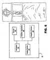
- FIG. 1shows a schematic view of a system 10 for ablating tissue in accordance with the present invention.
- the tissue to be ablatedwill be located within the body cavity, such as the endocardial or epicardial tissue of the heart.
- Other body organ tissue, such as the liver or lungs,can also be ablated using the present invention.
- System 10may also be used in any location where it is necessary to measure tissue temperature, such as during ventricular ablation.
- System 10may include an ablation device 20 that comprises at least one conductive electrode 22, and a connection 28 to a source of ablation energy.
- System 10may further include a power source 30 that provides ablation energy.
- System 10may further include a sensor 24 that may be used to measure the energy being transmitted through the electrode 22 to the target tissue 60.
- System 10also may include an irrigation source 40 that provides irrigation fluid to the ablation site.
- Ablation device 20 or electrode 22 of ablation device 20may also include fluid openings 46 through which irrigation fluid may flow to the site via fluid conduit 26.
- System 10may also include an indifferent (or non-ablating) electrode 23 which may serve as the return plate for energy transmitted through electrode 22.
- Ablation device 20may be any suitable ablation tool such as, for example, a catheter, an electrocautery device, an electrosurgical device, a suction-assisted ablation tool, an ablation pod, an ablation paddle, an ablation hemostat or an ablation wire.
- Ablation device 20 and its componentsare preferably made of a biocompatible material such as stainless steel, biocompatible epoxy or biocompatible plastic.
- a biocompatible materialprompts little allergenic response from the patient's body and is resistant to corrosion from being placed within the patient's body.
- the biocompatible materialpreferably does not cause any additional stress to the patient's body, for example, it does not scrape detrimentally against any elements within the surgical cavity.
- ablation device 20may be permanently or removably attached to or incorporate a maneuvering apparatus for manipulating device 20 onto a tissue surface.
- a maneuvering apparatusfor manipulating device 20 onto a tissue surface.
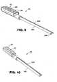
- Such an apparatusmay be, for example, a pen-like maneuvering handle 12.
- Electrodes of ablation device 20may also be located on one or more jaws of a hemostat-like device.
- ablation device 20may also be used in conjunction with a traditional catheter, for example, in a closed heart ablation procedure.
- Ablation device 20may also be maneuvered with a leash or pull-wire assembly.
- any appropriate flexible or rigid handlemay be used as a maneuvering apparatus.
- any appropriate endoscopic or thoroscopic maneuvering apparatusmay also be used with device 20.
- Device 20also preferably includes a connection 28 suitable for conducting energy to device 20, particularly to conductive element 22 from a power source.
- the conductive element 22 of ablation device 20is preferably an electrode.
- This electrode 22may be positioned in any suitable place on device 20.
- Preferably electrode 22is placed near an end of the device 20, away from the user, to be more easily manipulated against the tissue 60 to be ablated.
- Electrode 22may be, for example, a weeping electrode, a double wound coil electrode, an electrode needle or any other suitable electrode.
- System 10also includes sensor 24.
- Sensor 24may comprise one or more temperature-sensing elements 34 placed on or integrated into a support surface 44. Temperature-sensing elements may be, for example, thermocouples or thermisters. Preferably, elements 34 are arranged in a grid on support surface 44. Preferably, elements 34 are arranged in close proximity to each other.
- Support surface 44may be a rigid material such as, for example, PlexiglasTM. Support surface 44 may also be a flexible material such as, for example, biocompatible rubber or plastic. Alternatively, support surface 44 may be made of any material that may appropriately incorporate temperature-sensing elements 34.
- Sensor 24may be powered by any suitable power source. Connection 28 described above may provide power to sensor 24 from power source 30. Sensor 24 may also have its own connection and/or its own power source.
- Electrode 23may serve as the return plate for energy transmitted through electrode 22.
- Electrode 23may be, for example, a weeping electrode, a double wound coil electrode, an electrode needle or any other suitable electrode.
- An electrically conductive element incorporated into sensor 24may serve as the electrode 23.
- sensor 24may be electrically conductive and serve as electrode 23.
- Electrodes 22, 23may act as anode and cathode to each other, completing a bipolar system. If electrodes 22 and 23 are close to each other, the electric current has less area to cross. This is beneficial because the current is less likely to cross into undesired areas (for example, tissue other than target tissue). Such a bipolar system is also known to create narrower and deeper lesions. Incorporation of electrode 23 into sensor 24 may facilitate such a bipolar system.
- FIG. 2shows a target tissue surface 60.
- target tissuemay have two surfaces 62, 64.
- Front surface 62is the surface that may contact the ablation device 20.
- Back surface 64is the surface that may contact sensor 24.
- support surface 44is made of a material that may conform to surface 64 of the target tissue.
- a usermanipulates ablation device 20 so that electrode 22 contacts the surface 62 of the tissue to be ablated.
- Power source 30provides energy to the device 20 via connection 28. This connection may be any suitable connection for conducting energy from power source 30 to device 20.
- Power source 30may be any suitable power source such as, for example, standard electrical power available in the operating room.
- the useruses device 20 to ablate the tissue surface 62 with energy from the energized electrode 22.
- a top view of the lesion resulting from this ablation processis shown at 72.
- Lesion 72is a continuous lesion.
- lesion 72may not be continuous on back surface 64 of the tissue. Areas 74 of the lesion 72 are transmural to surface 64. However, areas 75 are not transmural. In areas 75, ablation has not penetrated through the complete thickness of the tissue. Because the tissue to be ablated is usually still within a body cavity, the user may only have visual access to front surface 62. The user may have difficulty accessing back surface 64 of the target tissue to assess transmurality. If lesion 72 is incomplete, i.e. is not transmural, it may not be effective in its intended purpose, such as for example, to control an arrhythmia. An incomplete lesion may even cause trauma to the patient.
- a usermay use the system 10 of the present invention to assess transmurality.
- the userplaces sensor 24 against back surface 64 of the target tissue.
- Sensor 24may be any arrangement of temperature-sensing elements.
- Sensor 24may be held in place against surface 64 using any appropriate holding apparatus.
- Sensor 24may also be held in place manually.
- Sensor 24may be attached, for example, using suction elements, clamps or suture material.
- each temperature-sensing elementWhen positioned, each temperature-sensing element is in contact with an area of tissue (point of contact 70). As ablation occurs, each of the temperature-sensing elements 34 on support surface 44 senses the temperature of its point of contact 70. Each element creates a voltage corresponding to the temperature of the point of contact. Each element then transmits the voltage to a processor 200. Preferably the elements are arranged in close proximity to each other to better sense a continuous or nearly continuous area of tissue.
- the temperature of each point of contact 70may be displayed, for example, on a LCD or CRT monitor 210.
- the tissuewill change in temperature. Ablation may be performed by heating the tissue to a suitable temperature. In one embodiment, the temperature increase at the point of contact may be sensed. Alternatively, ablation may be performed by freezing the tissue to a suitable temperature (such as -20°C to -40°C). In another embodiment, the temperature decrease at the point of contact may be sensed. This temperature change may be shown on the monitor 210.
- the monitor 210may show the current temperature of each point of contact 70. The monitor 210 may also lock and display the maximum temperature achieved at each point of contact 70.
- the monitor 210may also indicate when each point of contact has reached an appropriate combination of temperature and time to ensure cell death.
- One such appropriate combinationmay be 60°C for 5 seconds.
- Another combinationmay be 55°C for 20 seconds.
- Another combinationmay be 50°C for 15 seconds.
- Temperature informationmay be displayed to the user in any other suitable manner, such as for example, displaying a virtual representation of sensor 24 and ablation lesion 72 on the monitor 210.
- the temperature combinations indicated abovemay indicate cell death.
- the usermay attempt to ablate from the area nearest to device 20 (surface 62) through the entire thickness of the target tissue to the area farthest from device 20 (surface 64). If the temperature of the surface farthest from device 20 (surface 64) is high enough to achieve cell death, the user may assume that the temperatures of the tissue nearer to device 20 are also high enough to achieve cell death. In such an instance, the user may assume that transmurality has been achieved.
- system 10provides feedback on display 210 regarding the temperature of the surface 64 farthest from device 20 and thereby provides feedback on the transmurality of lesion 72.
- the signal from sensor 24may preferably be amplified by a suitable amplifier 220 before reaching processor 200.
- the amplifiermay also be incorporated into processor 200. Alternatively, the amplifier may be a separate device.
- sensor 24may be made of a rigid piece of material.
- the materialmay have a plurality of thermocouples attached in a grid configuration to its surface.
- fifteen thermocouplesare glued in a 3x5 grid to a rigid piece of PlexiglasTM.
- the thermocouplesmay be positioned approximately 2 to 3 mm apart from each other.
- the thermocouplesare wired to a computer.
- Each thermocouplemay be displayed as a dot or square on the monitor of the computer.
- Each of the thermocouple elementsmay contact a point on a target tissue. When the point on the target tissue reaches a certain temperature, the corresponding thermocouple element may send a signal to the computer.
- the temperature-sensing elementsmay send constant signals to the computer.
- the thermocouplesmay send a constant signal to the computer based on their voltage. As the temperature changes, the voltage of the thermocouples may change proportionately and the signal sent by the thermocouples may change proportionately.
- the corresponding dot or square on the monitoris then colored to indicate that a certain temperature has been reached.
- the corresponding dot or squaremay change color along with the temperature. For example, a dot may start out as blue when a thermocouple element first contacts the target tissue. Then the dot may turn yellow as the thermocouple element senses the tissue temperature to be 30°C. Finally the dot may turn red as the thermocouple element senses the tissue temperature to be 60°C.
- sensor 24may also be a disposable pad 400.
- Temperature-sensing elements 34may be incorporated into this pad. These elements may be, for example, temperature-sensing liquid crystals or other chemical compounds such as those commonly used by medical professionals for disposable thermometer strips. Elements 34 may also be arranged in a grid configuration. Alternatively, elements 34 may be arranged so that they fill pad 400.
- pad 400may be two sealed layers of material filled with temperature-sensing liquid crystals. Preferably, the layers may be sealed to ensure biocompatibility. Preferably, the layers may provide a time lag for heating the temperature-sensing elements 34 within pad 400. Such an arrangement may provide a surface that may more fully contact surface 64. The points of contact 70 on such an area may be nearly continuous.
- Pad 400may be placed against the surface 64 of the tissue to be ablated.
- Pad 400may have a corresponding color scale (not shown). This color scale may indicate, for example, the current temperature, the maximum temperature achieved or that the tissue has reached a combination of temperature and time to ensure cell death.
- pad 400may view pad 400 to see a visual representation of the temperature of surface 64.
- pad 400may be uniformly grey when first placed against surface 64. Then the pad 400 may turn darker grey when contacted against temperatures of about -20°C. Finally the pad 400 may turn black when contacted against temperatures of about -40°C.
- pad 400shows a representation 472 of lesion 72 that was created on surface 62. Using the grey/dark grey/black color scheme described above as an example, representation 472 indicates that lesion 72 has a temperature on the surface 64 of approximately -40°C at the points that appear black in the representation. Lesion 72 has a temperature on surface 64 of approximately -20°C at the points that appear dark grey in the representation.
- Lesion 72has a temperature on surface 64 of greater than -20°C at the portions that appear grey in the representation. A user may regard such a representation and determine that the dark grey portions and the grey portions of the lesion 72 need additional ablation. Additionally, a grid or other guide may be marked on pad 400 to aid the user in visualizing the lesion's placement
- the usermay temporarily remove the pad to see whether the temperature of surface 64 is sufficient to achieve transmurality.
- the usermay determine, based on the temperatures, that the dark grey portions and the grey portions of the lesion are not transmural.
- the usermay then replace pad 400 and go back over the lesion with the ablation device 20 until the desired temperature is achieved.
- the desired temperaturemay correspond to transmurality as described above.
- Pad 400may also be disposed after it is removed. A new pad may be placed under the lesion and the user may continue to ablate with device 20 and the new pad.
- Electrode 423may serve as the return plate for energy transmitted through electrode 22.
- Electrode 423may be, for example, a weeping electrode, a double wound coil electrode, an electrode needle or any other suitable electrode.
- An electrically conductive element incorporated into pad 400may serve as the electrode 423.
- pad 400may be electrically conductive and serve as electrode 423.
- Electrodes 22, 423may act as anode and cathode to each other, completing a bipolar system. If electrodes 22 and 423 are close to each other, the electric current has less area to cross. This is beneficial because the current is less likely to cross into undesired areas (for example, tissue other than target tissue). Such a bipolar system is also known to create narrower and deeper lesions. Incorporation of electrode 423 into pad 400 may facilitate such a bipolar system.
- sensor 24may be a finger pad 624.
- Sensor 24may be mounted on a glove or a portion of a glove to form finger pad 624.
- finger pad 624may be formed of a material that may be used to cover a fingertip.
- finger pad 624may be thermally insulated to protect the user.
- finger pad 624may be uniformly blue when first placed against surface 64. Then the finger pad 624 may turn yellow when contacted against temperatures of about 30°C. Finally the finger pad 624 may turn red when contacted against temperatures of about 60°C.
- a gridmay be marked on the pad 624 to aid the user in visualizing the lesion's placement.
- the usermay temporarily remove finger pad 624 from contact with surface 64.
- the usermay then visually check the representation of the lesion displayed on finger pad 624.
- the representationmay resemble, for example, whether the temperature of surface 64 is sufficient to achieve transmurality. If not, the user may replace finger pad 624 and go back over the lesion with the ablation device 20 until the desired temperature is achieved.
- Finger pad 624may also be disposed after it is removed. A new pad may be placed under the lesion and the user may continue to ablate with device 20 and the new pad.
- FIG. 7shows another embodiment of the temperature-sensing device of the present invention.
- pad 700may incorporate temperature-sensing elements in a three-dimensional arrangement
- Temperature-sensing elements 734may be positioned so that they may be located within the tissue 760 itself.
- a temperature-sensing elementmay be located at point 780 on the tip of a structure 782 for penetrating into the tissue.
- This structuremay be any suitable element for positioning the elements 734 within the tissue, such as, for example, a needle.
- Temperature-sensing elementsmay be arranged on one or more of these structures 782.
- Temperature-sensing elements 734may convey signals corresponding to the temperature of the tissue being ablated as described above.
- irrigation fluidwhich may be, for example, any suitable fluid such as saline or another conductive fluid.
- the irrigating fluidmay cool the electrode 22 of ablation device 20 and may allow for greater lesion depth. Furthermore, continuous fluid flow may keep the ablation device surface temperature below the threshold for blood coagulation, which may also clog the device. Use of irrigating fluid may therefore reduce the need to remove a clogged ablation device for cleaning or replacement.
- the presence of an ionic fluid layer between electrode 22 and the tissue to be ablatedmay also ensure that an ionic fluid layer conforming to the tissue contours is created.
- saline solutionis used.
- Irrigation source 40may be any suitable source of irrigation fluid such as, for example, a standard irrigation pump (not shown). This pump may also be connected to power source 30 or may have its own source of power.
- device 20also includes means for delivering irrigation to the ablation site from irrigation source 40. Such means may be, for example, fluid openings 46 which may be delivered to the electrode via, for example, fluid conduit 26.
- System 10may also include an indifferent electrode 23 which may serve as the return plate for energy transmitted through electrode 22.
- An electrically conductive elementmay be incorporated into sensor 24 or pad 400.
- sensor 24 or pad 400may be electrically conductive and serve as electrode 23.
- electrode 23may be a separate electrically conductive element. Electrode 23 may be placed elsewhere on the patient's body than the ablation site. For example, electrode 23 may be placed on the patient's back or shoulder.
- the senor for assessing transmurality of the present inventionmay be used in a variety of ablation systems such as those available from Medtronic, Inc., Minneapolis, Minnesota.
- FIG. 8shows a schematic view of another embodiment of system 10 for ablating tissue in accordance with the present invention.
- system 10is shown to comprise ablation device 20, an output device 25, an irrigation source 40, a generator 80, and a sensor 24.
- system 10may also include an indifferent (non-ablating) electrode 23 (not shown in Fig. 6). As shown in Fig. 1, the indifferent electrode 23 may be placed elsewhere on the patient's body such as the back, thigh or shoulder or another site other than the ablation site.
- Ablation device 20may comprise one or more suction elements and a suction conduit that provides suction from a suction source. Ablation device 20 may also comprise a conduit that provides irrigation fluid from irrigation source 40. In addition, ablation device 20 may comprise a connector for connecting ablation device 20 to generator 80.
- ablation device 20 and its componentsare preferably made of a biocompatible material.
- Biocompatible materials or biomaterialsare usually designed and constructed to be placed in or onto tissue of a patient's body or to contact fluid of a patient's body.
- a biomaterialwill not induce undesirable reactions in the body such as blood clotting, tumor formation, allergic reaction, foreign body reaction (rejection) or inflammatory reaction; will have the physical properties such as strength, elasticity, permeability and flexibility required to function for the intended purpose; may be purified, fabricated and sterilized easily; will substantially maintain its physical properties and function during the time that it remains in contact with tissues or fluids of the body.
- Materials that are either biocompatible or may be modified to be biocompatible and may be used to make ablation device 20, sensor 24 and/or one or more of their componentsmay include metals such as titanium, titanium alloys, TiNi alloys, shape memory alloys, super elastic alloys, aluminum oxide, platinum, platinum alloys, stainless steels, stainless steel alloys, MP35N, elgiloy, haynes 25, stellite, pyrolytic carbon, silver carbon, glassy carbon, polymers or plastics such as polyamides, polycarbonates, polyethers, polyesters, polyolefins including polyethylenes or polypropylenes, polystyrenes, polyurethanes, polyvinylchlorides, polyvinylpyrrolidones, silicone elastomers, fluoropolymers, polyacrylates, polyisoprenes, polytetrafluoroethylenes, rubber, minerals or ceramics such as hydroxapatite, epoxies, human or animal protein or tissue such as bone, skin,
- One or more surfaces of ablation device 20, sensor 24 and/or their componentsmay be coated with one or more radioactive materials and/or biological agents such as, for example, an anticoagulant agent, an antithrombotic agent, a clotting agent, a platelet agent, an anti-inflammatory agent, an antibody, an antigen, an immunoglobulin, a defense agent, an enzyme, a hormone, a growth factor, a neurotransmitter, a cytokine, a blood agent, a regulatory agent, a transport agent, a fibrous agent, a protein, a peptide, a proteoglycan, a toxin, an antibiotic agent, an antibacterial agent, an antimicrobial agent, a bacterial agent or component, hyaluronic acid, a polysaccharide, a carbohydrate, a fatty acid, a catalyst, a drug, a vitamin, a DNA segment, a RNA segment, a nucleic acid, a lectin, an antiviral agent, a viral
- Ablation device 20may comprise a surgeon controlled switch.
- a switchmay be incorporated in or on ablation device 20 or any other location easily and quickly accessed by the surgeon for regulation of ablation device 20 by the surgeon.
- the switchmay be, for example, a hand switch, a foot switch, or a voice-activated switch comprising voice-recognition technologies.
- a visual and/or audible signal used to alert a surgeon to the completion or resumption of ablationmay be incorporated into ablation device 20.
- a beeping tone or flashing lightthat increases in frequency as the ablation period ends or begins may be used.
- Ablation device 20may be positioned and used, for example, through a thoracotomy, through a sternotomy, percutaneously, transvenously, arthroscopically, endoscopically, for example, through a percutaneous port, through a stab wound or puncture, through a small incision, for example, in the chest, in the groin, in the abdomen, in the neck or in the knee, or in combinations thereof. It is contemplated that ablation device 20 may be used, for example, in open-chest surgery on a heart in which the sternum is split and the rib cage opened with a retractor. It is also contemplated that ablation device 20 may be used, for example, in closed-chest surgery on a heart in which the sternum is not split
- System 10may also include a suction source (not shown) for providing suction to ablation device 20 and/or sensor 24.
- Ablation device 20may comprise one or more suction devices, elements, or ports to better anchor ablation device 20 to tissue. Suction may also be used to anchor sensor 24 to a surface of tissue.
- Fig. 9shows an alternative embodiment of sensor 24 comprising a plurality of suction openings or ports 986 positioned along a tissue contact or support surface 44 comprising a plurality of temperature-sensing elements 34.
- Sensor 24may comprise one or more suction elements, openings, orifices or ports positioned or integrated within or along a tissue contact or support surface. Suction openings of ablation device 20 and sensor device 24 may communicate suction through a tissue contact surface to the atmosphere.
- Sensor 24may be powered by any suitable power source.
- connection 928may provide power to sensor 24 from power source 30, generator 80, output device 25, or processor 200.
- Support surface 44may be attached to a flexible or rigid hose or tubing for supplying suction from a suitable suction source to the target tissue surface through suction ports 986 of sensor 24.
- Support surface 44may be attached to a maneuvering means for placing or positioning elements 34 against tissue.
- sensor 24may comprise shaft or handle 985 coupled to support surface 44.
- Handle 985may comprise suction lumen 988 for communicating suction from a suitable suction source to the target tissue surface through suction ports 986 of sensor 24.
- Suction conduit or lumen 988may be connected to least one suction port 986 containing a suction opening.
- Suction ports 986may be arranged in any suitable fashion, such as a row or circle. In addition, the specific number of ports and their position may vary.
- Sensor 24may be covered with a removable covering during insertion into a patient's body to prevent blood or tissue from clogging suction openings 986, although this is not necessary.
- Such coveringsmay include coverings of biocompatible material that would cover sensor 24.
- coveringsmay be placed over ports 986, such as, for example, mesh coverings or ribbed coverings.
- Each suction port or opening 986may have a suction aperture coupling port 986 with conduit 988.
- Suction aperturemay be located in the center or at a position slightly off-center of suction port 986.
- Suction aperturemay be any shape including circular.
- the suction ports 986may also be any suitable shape, for example circular, oval, rectangular, or triangular.
- each suction aperturewould have a smaller diameter than the area of suction port 986. This creates a high resistance pathway between suction port 986 and suction conduit 988. Because of this, loss of a tissue-to-port seal in one suction port (and thus loss of fixation of the suction port to the tissue) should not cause a precipitous pressure drop in the remainder of the suction ports.
- Suctionmay be provided to ablation device 20 and/or sensor 24 by the standard suction available in the operating room.
- the suction sourcemay be coupled to ablation device 20 and/or sensor 24 with a buffer flask.
- Suctionmay be provided at a negative pressure of between 26.64-79.92 kPa (200-600 mm Hg) with 53.25 kPa (400 mm Hg) preferred.
- suctionmay be provided via a manual or electric pump, a syringe, a suction or squeeze bulb or other suction or vacuum producing means, device.or system.
- the suction sourcemay comprise one or more vacuum regulators, valves, e.g., vacuum releasing valves, conduits, lines, tubes and/or hoses.
- the conduits, lines, tubes, or hosesmay be flexible or rigid.
- a flexible suction linemay be used to communicate suction to ablation device 20 and/or sensor 24, thereby allowing ablation device 20 and/or sensor 24 to be easily manipulated by a surgeon.
- Another method that would allow the surgeon to easily manipulate ablation device 20 and/or sensor 24includes incorporation of a suction source into ablation device 20 and/or sensor 24.
- a small battery operated vacuum pumpmay be incorporated into ablation device 20 and/or sensor 24.
- the suction sourcemay be slaved to ablation device 20, output device 25, irrigation source 40, generator 80 and/or sensor 24.
- the suction sourcemay be designed to automatically stop suction when ablation is stopped and to start suction when ablation is began.
- the suction sourcemay include a visual and/or audible signal used to alert a surgeon to any change in suction. For example, a beeping tone or flashing light may be used to alert the surgeon when suction is present
- Fig. 10shows an alternative embodiment of sensor 24 comprising a plurality of temperature-sensing elements 34 aligned in a row on tissue contact or support surface 44.
- Tissue contact surface 44may be attached to shaft or handle 985.
- Handle 985may be rigid or flexible. Handle 985 may comprise one or more hinges or joints (not shown) for maneuvering and placing elements 34 against tissue. The hinges or joints of handle 985 may be actuated remotely, for example, from outside a patient's body. Handle 985 may be malleable or shapeable.
- Connection 928may provide power to sensor 24 from power source 30, generator 80, output device 25, or processor 200.
- Sensor 24may be positioned and used, for example, through a thoracotomy, through a sternotomy, percutaneously, transvenously, arthroscopically, endoscopically, for example, through a percutaneous port, through a stab wound or puncture, through a small incision, for example, in the chest, in the groin, in the abdomen, in the neck or in the knee, or in combinations thereof. It is contemplated that sensor 24 may be used, for example, in open-chest surgery on a heart in which the sternum is split and the rib cage opened with a retractor. It is also contemplated that sensor 24 may be used, for example, in closed-chest surgery on a heart in which the sternum is not split
- Sensor 24may include or be operatively coupled with a surgeon-controlled switch.
- a switchmay be incorporated in or on sensor 24 or any other location easily and quickly accessed by the surgeon for regulation of sensor 24 by the surgeon.
- the switchmay be, for example, a hand switch, a foot switch, or a voice-activated switch comprising voice-recognition technologies.
- Sensor 24may include, or may be coupled with a device that generates, a visual and/or audible signal used to alert a surgeon to any change in tissue temperature. For example, a beeping tone or flashing light may be used to alert the surgeon that a change has occurred in tissue temperature.
- Output device 25may receive and preferably interpret the signal from sensor 24.
- the signal from sensor 24may preferably be amplified by a suitable amplifier 220 before reaching output device 25 comprising processor 200.
- the amplifiermay be incorporated into output device 25.
- the amplifiermay be incorporated into sensor 24, ablation device 20 or generator 80.
- the amplifiermay be a separate device.
- Output device 25may be a device separate from ablation device 20, sensor 24, power source 30, irrigation source 40, or generator 80.
- Output device 25may be incorporated into ablation device 20, sensor 24, power source 30, irrigation source 40, or generator 80.
- Output device 25may control the power level from the power source 30 or generator 80.
- a signal of a first intensity from sensor 24may indicate that the power level from power source 30 should be lowered; a signal of a different intensity may indicate that the power source 30 should be turned off.
- output device 25may be configured so that it may automatically raise or lower the power from source 30 appropriately.
- the control of power source 30 based on output from output device 25may be manual.
- Output device 25may also be a visual display that indicates to the user that ablation energy should be halted.
- a displaymay be, for example, an indicator on a LCD or CRT monitor 210.
- the monitor 210may show the current temperature of each point of contact 70.
- the monitor 210may also lock and display the maximum temperature achieved at each point of contact 70.
- the monitor 210may also indicate when each point of contact has reached an appropriate combination of temperature and time to ensure cell death.
- One such appropriate combinationmay be 60°C for 5 seconds.
- Another combinationmay be 55°C for 20 seconds.
- Another combinationmay be 50°C for 15 seconds.
- Temperature informationmay be displayed to the user in any other suitable manner, such as for example, displaying a virtual representation of sensor 24 and ablation lesion 72 on the monitor 210.
- the monitormay display the voltage corresponding to the signal emitted from sensor 24. This signal corresponds in turn to the intensity of the temperature at the tissue site. Therefore a voltage level of 2 would indicate that the tissue was hotter than when the voltage level was 1. In this example, a user would monitor the voltage level and, if it exceeded a certain value, would turn off or adjust the power source 30.
- the display of device 25may alternatively be located on sensor 24 or ablation device 20.
- An indicatorsuch as an LED light, may be permanently or removably incorporated into sensor 24 or ablation device 20.
- the indicatormay receive a signal from sensor 24 indicating that the tissue had reached an appropriate temperature.
- the indicatormay turn on, change color, grow brighter or change in any suitable manner to indicate that the flow of power from source 30 should be modified or halted.
- the indicatormay also be located on power source 30, on generator 80, on irrigation source 40, or may be located on another location visible to the user.
- output device 25may be an audio device that indicates to the user that ablation energy should be halted.
- Such an audio devicemay be, for example, a speaker that broadcasts a sound (for example, a beep) that increases in intensity, frequency or tone as the temperature sensed by sensor 24 increases.
- the usermay adjust, for example, turn down or turn off power source 30 when the sound emitted reaches a given volume or level.
- the audio devicemay also give an audible signal (such as the message "turn off power source") when the temperature sensed by sensor 24 reaches a certain level.
- Such an audio devicemay be located on the sensor 24 or ablation apparatus 20, on power source 30, on generator 80, or on irrigation source 40.
- the audio devicemay also be a separate device.
- FIG. 11shows a flow diagram of one embodiment of the present invention.
- the patientis prepared for an ablation procedure at 1100.
- the initial state of tissue temperatureis measured (Block 1105).
- the initial state of tissue temperatureis then used as a gauge to compare with the state of tissue temperature during the procedure.
- ablation of the target tissueis begun (Block 1110).
- Tissue temperatureis then monitored (Blocks 1117 and 1125). If the tissue temperature becomes to hot, the energy supplied to ablation apparatus 20 is modified or adjusted (Blocks 1123 and 1128).
- Irrigation source 40may be any suitable source of irrigation fluid.
- Irrigation source 40may include a manual or electric pump, an infusion pump, a syringe pump, a syringe, a pressurized reservoir or bag, a squeeze bulb or other fluid moving means, device or system.
- a pumpmay be connected to power source 30 or it may have its own source of power.
- Irrigation source 40may be powered by AC current, DC current, or it may be battery powered either by a disposable or re-chargeable battery.
- Irrigation source 40may comprise one or more fluid regulators, e.g., to control fluid flow rate, valves, fluid reservoirs, conduits, lines, tubes and/or hoses.
- the conduits, lines, tubes, or hosesmay be flexible or rigid.
- a flexible linemay be used to communicate fluid to ablation device 20, thereby allowing ablation device 20 to be easily manipulated by a surgeon.
- Fluid reservoirsfor example, may be an IV bag or bottle. It is preferred that the irrigation fluid be sterile.
- Irrigation source 40may be incorporated into ablation device 20, thereby delivering irrigation fluid at the ablation site. Irrigation source 40 may be slaved to ablation device 20, output device 25, generator 80 and/or sensor 24. For example, irrigation source 40 may be designed to automatically stop or start the delivery of irrigation fluid during ablation of tissue. Irrigation source 40 may be slaved to a robotic system or a robotic system may be slaved to irrigation source 40.
- Irrigation source 40may comprise a surgeon-controlled switch.
- a switchmay be incorporated in or on irrigation source 40 or any other location easily and quickly accessed by the surgeon for regulation of irrigation fluid delivery by the surgeon.
- the switchmay be, for example, a hand switch, a foot switch, or a voice-activated switch comprising voice-recognition technologies.
- Irrigation source 40may include a visual and/or audible signal used to alert a surgeon to any change in the delivery of irrigation fluid. For example, a beeping tone or flashing light may be used to alert the surgeon that a change has occurred in the delivery of irrigation fluid.
- an irrigation fluidmay include saline, e.g., normal, hypotonic or hypertonic saline, Ringer's solution, ionic contrast, blood, or other energy-conducting liquids.
- An ionic irrigation fluidelectrically couples the one or more electrodes of ablation device 20 to the tissue to be ablated thereby lowering the impedance at the ablation site.
- An ionic irrigating fluidmay create a larger effective electrode surface.
- An irrigating fluidmay cool the surface of the tissue thereby preventing the over heating or cooking of tissue which can cause popping, desiccation, and charring of tissue.
- a hypotonic irrigating fluidmay be used to electrically insulate a region of tissue thereby preventing ablation of tissue by an electrical means.
- Diagnostic or therapeutic agentssuch as one or more radioactive materials and/or biological agents such as, for example, an anticoagulant agent, an antithrombotic agent, a clotting agent, a platelet agent, an anti-inflammatory agent, an antibody, an antigen, an immunoglobulin, a defense agent, an enzyme, a hormone, a growth factor, a neurotransmitter, a cytokine, a blood agent, a regulatory agent, a transport agent, a fibrous agent, a protein, a peptide, a proteoglycan, a toxin, an antibiotic agent, an antibacterial agent, an antimicrobial agent, a bacterial agent or component, hyaluronic acid, a polysaccharide, a carbohydrate, a fatty acid, a catalyst, a drug, a vitamin, a DNA segment, a RNA segment, a nucleic acid, a lectin, an antiviral agent, a viral agent or component, a genetic agent, a ligand
- Generator 80may comprise a control unit and power source 30.
- Ablation device 20may be permanently or removably attached to a source of energy such as electrical, radiofrequency (RF), laser, thermal, microwave or ultrasound or any other appropriate type of energy that may be used to ablate tissue.
- Generator 80may be powered by AC current, DC current or it may be battery powered either by a disposable or re-chargeable battery.
- Generator 80may be used to coordinate the various elements of system 10. For example, generator 80 may be configured to synchronize activation and deactivation of irrigation source 40 with ablation.
- Generator 80may incorporate a controller as described above or any suitable processor.
- the processormay process sensed information from sensor 24.
- the controllermay store and/or process such information before, during and/or after an ablation procedure.
- the patient's tissue temperaturemay be sensed, stored and processed prior to and during the ablation procedure.
- Generator 80may be used to control the power levels of ablation device 20. Generator 80 may also gather and process information from sensor 24. This information may be used to adjust power levels and ablation times. Generator 80 may incorporate one or more switches to facilitate regulation of the various system components by the surgeon.
- One example of such a switchis a foot pedal.
- the switchmay also be, for example, a hand switch, or a voice-activated switch comprising voice-recognition technologies.
- the switchmay be incorporated in or on one of the surgeon's instruments, such as surgical site retractor, e.g., a sternal or rib retractor, or ablation device 20, or any other location easily and quickly accessed by the surgeon.
- Generator 80may also include a display.
- Generator 80may also include other means of indicating the status of various components to the surgeon such as a numerical display, gauges, a monitor display or audio feedback.
- Generator 80may also incorporate a cardiac stimulator and/or cardiac monitor.
- electrodes used to stimulate or monitor the heartmay or may not be incorporated into ablation device 20 and/or sensor 24.
- Generator 80may comprise a surgeon-controlled switch for cardiac stimulation or monitoring, as discussed earlier.
- a switchmay be incorporated in or on generator 80 or any other location easily and quickly accessed by the surgeon for regulation of generator 80 by the surgeon.
- the switchmay be, for example, a hand switch, a foot switch, or a voice-activated switch comprising voice-recognition technologies.
- a visual and/or audible signal used to alert a surgeon to the completion or resumption of ablation, suction, sensing, monitoring, stimulation and/or delivery of irrigation fluid, drugs and/or cellsmay be incorporated into generator 80.
- a beeping tone or flashing lightthat increases in frequency as the ablation period ends or begins may be used.
- System 10may comprise one or more additional sensors besides sensor 24.
- ablation device 20may comprise one or more temperature-sensitive elements, such as a thermocouple, to allow a surgeon to monitor temperature changes of ablation device 20.
- system 10 or ablation device 20may comprise one or more sensors to sense and/or monitor voltage, amperage, wattage and/or impedance.
- system 10, ablation device 20, or sensor 24may comprise one or more blood gas sensors for measuring the concentration or saturation of a gas in the blood stream.
- system 10, ablation device 20, or sensor 24may comprise a sensor for measuring the concentration or saturation of oxygen or carbon dioxide in the blood.
- system 10, ablation device 20, or sensor 24may comprise one or more suitable sensors for measuring blood pressure or flow, for example a Doppler ultrasound sensor system, or a sensor for measuring hematocrit (HCT) levels.
- HCThematocrit
- system 10, ablation device 20, or sensor 24may comprise one or more biosensors, for example, comprising an immobilized biocatalyst, enzyme, immunoglobulin, bacterial, mammalian or plant tissue, cell and/or subcellular fraction of a cell.
- biosensorsfor example, comprising an immobilized biocatalyst, enzyme, immunoglobulin, bacterial, mammalian or plant tissue, cell and/or subcellular fraction of a cell.
- the tip of a biosensormay comprise a mitochondrial fraction of a cell, thereby providing the sensor with a specific biocatalytic activity.
- ablation device 20, or sensor 24may comprise one or more sensors based on potentiometric technology or fiber optic technology.
- the sensormay comprise a potentiometric or fiber optic transducer.
- An optical sensormay be based on either an absorbance or fluorescence measurement and may include an UV, a visible or an IR light source.
- System 10, ablation device 20, or sensor 24may comprise one or more sensors used to detect naturally detectable properties representative of one or more characteristics, e.g., chemical, physical or physiological, of a patient's bodily tissues or fluids.
- naturally detectable properties of patient's bodily tissues or fluidsmay include pH, fluid flow, electrical current, impedance, temperature, pressure, components of metabolic processes, chemical concentrations, for example, the absence or presence of specific peptides, proteins, enzymes, gases, ions, etc.
- System 10, ablation device 20, or sensor 24may comprise one or more imaging systems, camera systems operating in UV, visible, or IR range; electrical sensors; voltage sensors; current sensors; piezoelectric sensors; electromagnetic interference (EMI) sensors; photographic plates, polymer-metal sensors; charge-coupled devices (CCDs); photo diode arrays; chemical sensors, electrochemical sensors; pressure sensors, sound wave sensors; magnetic sensors; UV light sensors; visible light sensors; IR light sensors; radiation sensors; flow sensors; temperature sensors; vacuum sensors; or any other appropriate or suitable sensor.
- imaging systemscamera systems operating in UV, visible, or IR range
- electrical sensorsvoltage sensors; current sensors; piezoelectric sensors; electromagnetic interference (EMI) sensors
- photographic platespolymer-metal sensors
- charge-coupled devices (CCDs)charge-coupled devices
- photo diode arrayschemical sensors, electrochemical sensors; pressure sensors, sound wave sensors; magnetic sensors; UV light sensors; visible light sensors; IR light sensors; radiation sensors; flow sensors; temperature sensors; vacuum sensors; or any other appropriate or suitable sensor.
- Sensorsmay be incorporated into ablation device 20 or they may be placed or used at a location differing from the location of ablation device 20. For example, sensors may be placed in contact with the inside surface of a patient's heart while ablation device 20 is placed or used on the outside surface of the patient's heart.
- Ablation device 20, irrigation source 40 and/or generator 80may be slaved to one or more sensors.
- ablation device 20 and/or generator 80may be designed to automatically stop ablation if a sensor measures a predetermined sensor value, e.g., a particular temperature value.
- a sensor of the present inventionindicates that ablated tissue has reached a particular temperature, ablation is stopped automatically, thereby preventing charring of the tissue.
- Suctionmay also be slaved to one or more sensors.
- One or more sensors of the present inventionmay include a visual and/or audible signal used to alert a surgeon to any change in the one or more characteristics the sensor is monitoring. For example, a beeping tone or flashing light that increases in frequency as tissue temperature rises may be used to alert the surgeon.
- Ablation device 20, output device 25, irrigation source 40, generator 80, and/or sensor 24may be slaved to a robotic system or a robotic system may be slaved to ablation device 20, output device 25, irrigation source 40, generator 80, and/or sensor 24.
- Additional sensors and/or a suction sourcemay also be slaved to a robotic system or a robotic system may be slaved to the additional sensors and/or the suction source.
- Computer- and voice-controlled robotic systemsthat position and maneuver endoscopes and/or other surgical instruments for performing microsurgical procedures through small incisions may be used by the surgeon to perform precise and delicate maneuvers.. These robotic systems may allow the surgeon to perform a variety of microsurgical procedures including tissue ablation.
- robotic systemsmay include head-mounted displays which integrate 3-D visualization of surgical anatomy and related diagnostic and monitoring data, miniature high resolution 2-D and 3-D digital cameras, a computer, a high power light source and a standard video monitor.
- One or more of a variety of pharmacological agents or drugsmay be delivered or administered to an ablation patient, for a variety of functions and purposes as described below, prior to an ablation procedure, intermittently during an ablation procedure, continuously during an ablation procedure and/or following an ablation procedure.
- one or more of a variety of pharmacological agents or drugs, as discussed belowmay be delivered before, with or after the delivery of the irrigating fluid, as discussed earlier.
- Drugs, drug formulations or compositions suitable for administration to an ablation patientmay include a pharmaceutically acceptable carrier or solution in an appropriate dosage.
- a pharmaceutically acceptable carrier or solutionin an appropriate dosage.
- pharmaceutically acceptable carriersinclude a number of solutions, preferably sterile, for example, water, saline, Ringer's solution and/or sugar solutions such as dextrose in water or saline.
- Carrier solutionsmay or may not be buffered.
- Drug formulations or compositionsmay include antioxidants or preservatives such as ascorbic acid. They may also be in a pharmaceutically acceptable form for parenteral administration, for example to the cardiovascular system, or directly to the heart, such as intracoronary infusion or injection. Drug formulations or compositions may comprise agents that provide a synergistic effect when administered together. A synergistic effect between two or more drugs or agents may reduce the amount that normally is required for therapeutic delivery of an individual drug or agent Two or more drugs may be administered, for example, sequentially or simultaneously. Drugs may be administered via one or more bolus injections and/or infusions or combinations thereof. The injections and/or infusions may be continuous or intermittent.
- Drugsmay be administered, for example, systemically or locally, for example, to the heart, to a coronary artery and/or vein, to a pulmonary artery and/or vein, to the right atrium and/or ventricle, to the left atrium and/or ventricle, to the aorta, to the AV node, to the SA node, to a nerve and/or to the coronary sinus.
- Drugsmay be administered or delivered via intravenous, intracoronary and/or intraventricular administration in a suitable carrier.
- Examples of arteries that may be used to deliver drugs to the AV nodeinclude the AV node artery, the right coronary artery, the right descending coronary artery, the left coronary artery, the left anterior descending coronary artery and Kugel's artery.
- Drugsmay be delivered systemically, for example, via oral, transdermal, intranasal, suppository or inhalation methods. Drugs also may be delivered via a pill, a spray, a cream, an ointment or a medicament formulation.
- system 10may include a drug delivery device (not shown).
- the drug delivery devicemay comprise a catheter, such as a drug delivery catheter or a guide catheter, a patch, such as a transepicardial patch that slowly releases drugs directly into the myocardium, a cannula, a pump and/or a hypodermic needle and syringe assembly.
- a drug delivery cathetermay include an expandable member, e.g., a low-pressure balloon, and a shaft having a distal portion, wherein the expandable member is disposed along the distal portion.
- a catheter for drug deliverymay comprise one or more lumens and may be delivered endovascularly via insertion into a blood vessel, e.g., an artery such as a femoral, radial, subclavian or coronary artery.
- the cathetercan be guided into a desired position using various guidance techniques, e.g., flouroscopic guidance and/or a guiding catheter or guide wire techniques.
- Drugsmay be delivered via an iontophoretic drug delivery device placed on the heart.
- the delivery of ionized drugsmay be enhanced via a small current applied across two electrodes. Positive ions may be introduced into the tissues from the positive pole, or negative ions from the negative pole.
- the use of iontophoresismay markedly facilitate the transport of certain ionized drug molecules.
- lidocaine hydrochloridemay be applied to the heart via a drug patch comprising the drug.
- a positive electrodecould be placed over the patch and current passed.
- the negative electrodewould contact the heart or other body part at some desired distance point to complete the circuit
- One or more of the iontophoresis electrodesmay also be used as nerve stimulation electrodes or as cardiac stimulation electrodes.
- a drug delivery devicemay be incorporated into ablation device 20, thereby delivering drugs at or adjacent the ablation site or the drug delivery device may be placed or used at a location differing from the location of ablation device 20.
- a drug delivery devicemay be placed in contact with the inside surface of a patient's heart while ablation device 20 is placed or used on the outside surface of the patient's heart.
- the drug delivery devicemay be slaved to ablation device 20, output device 25, generator 80 and/or sensor 24.
- a drug delivery devicemay be designed to automatically stop or start the delivery of drugs during ablation of tissue.
- the drug delivery devicemay be slaved to a robotic system or a robotic system may be slaved to the drug delivery device.
- the drug delivery devicemay comprise a surgeon controlled switch.
- a switchmay be incorporated in or on the drug delivery device or any other location easily and quickly accessed by the surgeon for regulation of drug delivery by the surgeon.
- the switchmay be, for example, a hand switch, a foot switch, or a voice-activated switch comprising voice-recognition technologies.
- the drug delivery devicemay include a visual and/or audible signal used to alert a surgeon to any change in the delivery of drugs. For example, a beeping tone or flashing light that increases in frequency as the rate of drug delivery increases may be used to alert the surgeon.
- the two divisions of the autonomic nervous system that regulate the hearthave opposite functions.
- the adrenergic or sympathetic nervous systemincreases heart rate by releasing epinephrine and norepinephrine.
- the parasympathetic systemalso known as the cholinergic nervous system or the vagal nervous system decreases heart rate by releasing acetylcholine.
- Catecholaminessuch as norepinephrine (also called noradrenaline) and epinephrine (also called adrenaline) are agonists for beta-adrenergic receptors.
- An agonistis a stimulant biomolecule or agent that binds to a receptor.
- Beta-adrenergic receptor blocking agentscompete with beta-adrenergic receptor stimulating agents for available beta-receptor sites.
- receptor blocking agentsalso known as beta-adrenergic blockade
- the chronotropic or heart rate, inotropic or contractility, and vasodilator responses to receptor stimulating agentsare decreased proportionately. Therefore, beta-adrenergic receptor blocking agents are agents that are capable of blocking beta-adrenergic receptor sites.
- beta-adrenergic receptorsare concerned with contractility and heart rate
- stimulation of beta-adrenergic receptorsincreases heart rate, the contractility of the heart and the rate of conduction of electrical impulses through the AV node and the conduction system.
- Drugs, drug formulations and/or drug compositions that may be used according to this inventionmay include any naturally occurring or chemically synthesized (synthetic analogues) beta-adrenergic receptor blocking agents.
- Beta-adrenergic receptor blocking agents or ⁇ -adrenergic blocking agentsare also known as beta-blockers or ⁇ -blockers and as class II antiarrhythmics.
- beta-blockermay refer to one or more agents that antagonize the effects of beta-stimulating catecholamines by blocking the catecholamines from binding to the beta-receptors.
- beta-blockersinclude, but are not limited to, acebutolol, alprenolol, atenolol, betantolol, betaxolol, bevantolol, bisoprolol, carterolol, celiprolol, chlorthalidone, esmolol, labetalol, metoprolol, nadolol, penbutolol, pindolol, propranolol, oxprenolol, sotalol, teratolo, timolol and combinations, mixtures and/or salts thereof.
- beta-blockersmay be reversed by administration of beta-receptor agonists, e.g., dobutamine or isoproterenol.
- beta-receptor agonistse.g., dobutamine or isoproterenol.
- the parasympathetic or cholinergic systemparticipates in control of heart rate via the sinoatrial (SA) node, where it reduces heart rate.
- Other cholinergic effectsinclude inhibition of the AV node and an inhibitory effect on contractile force.
- the cholinergic systemacts through the vagal nerve to release acetylcholine, which, in turn, stimulates cholinergic receptors.
- Cholinergic receptorsare also known as muscarinic receptors. Stimulation of the cholinergic receptors decreases the formation of cAMP. Stimulation of cholinergic receptors generally has an opposite effect on heart rate compared to stimulation of beta-adrenergic receptors.
- beta-adrenergic stimulationincreases heart rate, whereas cholinergic stimulation decreases it
- vagal toneis high and adrenergic tone is low, there is a marked slowing of the heart (sinus bradycardia).
- Acetylcholineeffectively reduces the amplitude, rate of increase and duration of the SA node action potential.
- the SA nodedoes not arrest. Rather, pacemaker function may shift to cells that fire at a slower rate.
- acetylcholinemay help open certain potassium channels thereby creating an outward flow of potassium ions and hyperpolarization. Acetylcholine also slows conduction through the AV node.
- Drugs, drug formulations and/or drug compositions that may be used according to this inventionmay include any naturally occurring or chemically synthesized (synthetic analogues) cholinergic agent
- cholinergic agentappearing herein may refer to one or more cholinergic receptor modulators or agonists.
- cholinergic agentsinclude, but are not limited to, acetylcholine, carbachol (carbamyl choline chloride), bethanechol, methacholine, arecoline, norarecoline and combinations, mixtures and/or salts thereof.
- Drugs, drug formulations and/or drug compositions that may be used according to this inventionmay include any naturally occurring or chemically synthesized cholinesterase inhibitor.
- the term "cholinesterase inhibitor” appearing hereinmay refer to one or more agents that prolong the action of acetylcholine by inhibiting its destruction or hydrolysis by cholinesterase. Cholinesterase inhibitors are also known as acetylcholinesterase inhibitors. Examples of cholinesterase inhibitors include, but are not limited to, edrophonium, neostigmine, neostigmine methylsulfate, pyridostigmine, tacrine and combinations, mixtures and/or salts thereof.
- ion-selective channelswithin certain cell membranes. These ion selective channels include calcium channels, sodium channels and/or potassium channels. Therefore, other drugs, drug formulations and/or drug compositions that may be used according to this invention may include any naturally occurring or chemically synthesized calcium channel blocker.
- Calcium channel blockersinhibit the inward flux of calcium ions across cell membranes of arterial smooth muscle cells and myocardial cells. Therefore, the term "calcium channel blocker" appearing herein may refer to one or more agents that inhibit or block the flow of calcium ions across a cell membrane.
- the calcium channelis generally concerned with the triggering of the contractile cycle. Calcium channel blockers are also known as calcium ion influx inhibitors, slow channel blockers, calcium ion antagonists, calcium channel antagonist drugs and as class IV antiarrhythmics.
- a commonly used calcium channel blockeris verapamil.
- a calcium channel blockere.g., verapamil
- a calcium channel blockergenerally prolongs the effective refractory period within the AV node and slows AV conduction in a rate-related manner, since the electrical activity through the AV node depends significantly upon the influx of calcium ions through the slow channel.
- a calcium channel blockerhas the ability to slow a patient's heart rate, as well as produce AV block.
- calcium channel blockersexamples include, but are not limited to, amiloride, amlodipine, bepridil, diltiazem, felodipine, isradipine, mibefradil, nicardipine, nifedipine (dihydropyridines), nickel, nimodinpine, nisoldipine, nitric oxide (NO), norverapamil and verapamil and combinations, mixtures and/or salts thereof.
- Verapamil and diltiazemare very effective at inhibiting the AV node, whereas drugs of the nifedipine family have a lesser inhibitory effect on the AV node.
- Nitric oxide (NO)indirectly promotes calcium channel closure.
- NOmay be used to inhibit contraction. NO may also be used to inhibit sympathetic outflow, lessen the release of norepinephrine, cause vasodilation, decrease heart rate and decrease contractility. In the SA node, cholinergic stimulation leads to formation of NO.
- drugs, drug formulations and/or drug compositionsmay include any naturally occurring or chemically synthesized sodium channel blocker.
- Sodium channel blockersare also known as sodium channel inhibitors, sodium channel blocking agents, rapid channel blockers or rapid channel inhibitors.
- Antiarrhythmic agents that inhibit or block the sodium channelare known as class I antiarrhythmics, examples include, but are not limited to, quinidine and quinidine-like agents, lidocaine and lidocaine-like agents, tetrodotoxin, encainide, flecainide and combinations, mixtures and/or salts thereof.
- sodium channel blockermay refer to one or more agents that inhibit or block the flow of sodium ions across a cell membrane or remove the potential difference across a cell membrane.
- the sodium channelmay also be totally inhibited by increasing the extracellular potassium levels to depolarizing hyperkalemic values, which remove the potential difference across the cell membrane. The result is inhibition of cardiac contraction with cardiac arrest (cardioplegia). The opening of the sodium channel (influx of sodium) is for swift conduction of the electrical impulse throughout the heart.
- potassium channel agentappearing herein may refer to one or more agents that impact the flow of potassium ions across the cell membrane.
- the first type of channelis voltage-gated and the second type is ligand-gated.
- Acetylcholine-activated potassium channelswhich are ligand-gated channels, open in response to vagal stimulation and the release of acetylcholine. Opening of the potassium channel causes hyperpolarization, which decreases the rate at which the activation threshold is reached.
- Adenosineis one example of a potassium channel opener.
- Adenosineslows conduction through the AV node.
- Adenosinea breakdown product of adenosine triphosphate, inhibits the AV node and atria.
- adenosinecauses the shortening of the action potential duration and causes hyperpolarization.
- adenosinehas similar effects and also decreases the action potential amplitude and the rate of increase of the action potential.
- Adenosineis also a direct vasodilator by its actions on the adenosine receptor on vascular smooth muscle cells.
- adenosineacts as a negative neuromodulator, thereby inhibiting release of norepinephrine.
- Class III antiarrhythmic agentsalso known as potassium channel inhibitors lengthen the action potential duration and refractoriness by blocking the outward potassium channel to prolong the action potential.
- Amiodarone and d-sotalolare both examples of class III antiarrhythmic agents.
- Potassiumis the most common component in cardioplegic solutions. High extracellular potassium levels reduce the membrane resting potential. Opening of the sodium channel, which normally allows rapid sodium influx during the upstroke of the action potential, is therefore inactivated because of a reduction in the membrane resting potential.
- Drugs, drug formulations and/or drug compositions that may be used according to this inventionmay comprise one or more of any naturally occurring or chemically synthesized beta-blocker, cholinergic agent, cholinesterase inhibitor, calcium channel blocker, sodium channel blocker, potassium channel agent, adenosine, adenosine receptor agonist, adenosine deaminase inhibitor, dipyridamole, monoamine oxidase inhibitor, digoxin, digitalis, lignocaine, bradykinin agents, serotoninergic agonist, antiarrythmic agents, cardiac glycosides, local anesthetics and combinations or mixtures thereof. Digitalis and digoxin both inhibit the sodium pump.
- Digitalisis a natural inotrope derived from plant material, while digoxin is a synthesized inotrope. Dipyridamole inhibits adenosine deaminase, which breaks down adenosine. Drugs, drug formulations and/or drug compositions capable of reversibly suppressing autonomous electrical conduction at the SA and/or AV node, while still allowing the heart to be electrically paced to maintain cardiac output may be used according to this invention.
- Beta-adrenergic stimulation or administration of calcium solutionsmay be used to reverse the effects of a calcium channel blocker such as verapamil.
- Agents that promote heart rate and/or contractionmay be used in the present invention.
- dopaminea natural catecholamine
- Positive inotropesare agents that specifically increase the force of contraction of the heart.
- Glucagona naturally occurring hormone, is known to increase heart rate and contractility.
- Glucagonmay be used to reverse the effects of a beta-blocker since its effects bypass the beta receptor.
- Forskolinis known to increase heart rate and contractility.
- epinephrine and norepinephrinenaturally increase heart rate and contractility.
- Thyroid hormone, phosphodiesterase inhibitors and prostacyclin, a prostaglandinare also known to increase heart rate and contractility.
- methylxanthinesare known to prevent adenosine from interacting with its cell receptors.
- Radioactive materials and/or biological agentssuch as, for example, an anticoagulant agent, an antithrombotic agent, a clotting agent, a platelet agent, an anti-inflammatory agent, an antibody, an antigen, an immunoglobulin, a defense agent, an enzyme, a hormone, a growth factor, a neurotransmitter, a cytokine, a blood agent, a regulatory agent, a transport agent, a fibrous agent, a protein, a peptide, a proteoglycan, a toxin, an antibiotic agent, an antibacterial agent, an antimicrobial agent, a bacterial agent or component, hyaluronic acid, a polysaccharide, a carbohydrate, a fatty acid, a catalyst, a drug, a vitamin, a DNA segment, a RNA segment, a nucleic acid, a lectin, an antiviral agent, a viral agent or component, a genetic agent, a ligand and a dye (which acts),
- the ablation proceduremay be non-invasive, minimally invasive and/or invasive.
- the ablation proceduremay entail a port-access approach, a partially or totally endoscopic approach, a sternotomy approach or a thoracotomy approach.
- the ablation proceduremay include the use of various mechanical stabilization devices or techniques as well as various robotic or imaging systems.
- mechanical stabilization and manipulation devicesare described in U.S. Patent No. 5,836,311 ; 5,927,284 and 6,015,378 , and coassigned US Patent Applications Serial No. 09/396,047, filed September 15, 1999 , Serial No. 09/559,785, filed April 27, 2000 , and Serial No. 09/678,203, filed October 2, 2000 ; and European Patent Publication No. EP 0 993 806 .
- the heartmay be temporarily slowed or intermittently stopped for short periods of time to permit the surgeon to accomplish a required surgical task and yet still allow the heart itself to supply blood circulation to the body.
- stimulation of the vagus nerve in order to temporarily and intermittently slow or stop the heartis described in U.S. Patent No. 6,006,134 entitled “Method and Device for Electronically Controlling the Beating of a Heart Using Venous Electrical Stimulation of Nerve Fibers", Dec. 21, 1999, to Hill and Junkman. This patent is assigned to Medtronic, Inc.
Landscapes
- Health & Medical Sciences (AREA)
- Life Sciences & Earth Sciences (AREA)
- Surgery (AREA)
- Engineering & Computer Science (AREA)
- Veterinary Medicine (AREA)
- General Health & Medical Sciences (AREA)
- Physics & Mathematics (AREA)
- Public Health (AREA)
- Biomedical Technology (AREA)
- Heart & Thoracic Surgery (AREA)
- Medical Informatics (AREA)
- Molecular Biology (AREA)
- Animal Behavior & Ethology (AREA)
- Otolaryngology (AREA)
- Plasma & Fusion (AREA)
- Nuclear Medicine, Radiotherapy & Molecular Imaging (AREA)
- Immunology (AREA)
- Vascular Medicine (AREA)
- Biophysics (AREA)
- Pathology (AREA)
- Surgical Instruments (AREA)
Abstract
Description
- This invention relates to ablation devices that are used to create lesions in tissue. More particularly, this invention relates to ablation devices that use temperature-sensing elements to monitor the transmurality of the lesions.
- The action of the heart is known to depend on electrical signals within the heart tissue. Occasionally, these electrical signals do not function properly. The maze procedure is a surgical operation for patients with atrial fibrillation that is resistant to medical treatment. In this procedure, incisions are created in the right and left atria to produce an orderly passage of the electrical impulse from the SA node to the atrioventricular node. Blind passageways are also created to suppress reentry cycles. Currently, the lesions may still be created using a traditional cut and sew technique. The scar tissue resulting from the procedure results in a non-conductive lesion.
- Ablation of cardiac conduction pathways in the region of tissue where the signals are malfunctioning is now being used to replace the surgical incisions. Ablation is also used therapeutically with other organ tissue, such as the lungs, liver, prostate and uterus. Ablation may also be used in treatment of disorders such as tumors, cancers or undesirable growth.
- Currently, electrophysiology (EP) ablation devices generally have one or more electrodes at their tips. These may be used for both diagnosis and therapy. In one instance, electrodes at the tips of EP ablation devices allow the physician to measure electrical signals along the surface of the heart. This is called mapping. When necessary, in another instance, the physician can also ablate certain tissues using, typically, radio frequency (RF) energy conducted to one or more ablation electrodes.
- Sometimes ablation is necessary only at discrete positions along the tissue. This is the case, for example, when ablating accessory pathways, such as in Wolff-Parkinson-White syndrome or AV nodal reentrant tachycardias. At other times, however, ablation is desired along a line, called linear ablation. This is the case for atrial fibrillation, where the aim is to reduce the total mass of contiguous (electrically connected) atrial tissue below a threshold believed to be critical for sustaining multiple reentrant wavelets. Linear lesions are created between electrically non-conductive anatomic landmarks to reduce the contiguous atrial mass.
- Linear ablation is currently accomplished in one of several ways. One way is to position the tip portion of the ablation device so that an ablation electrode is located at one end of the target site. This may be done, for example, with an electrode positioned on a "pen-like" device. Then energy is applied to the electrode to ablate the tissue adjacent to the electrode. The tip portion of the electrode is then slid along the tissue to a new position and then the ablation process is repeated. This is sometimes referred to as the "spot burn" technique. This technique is time-consuming (which is not good for the patient) and requires multiple accurate placements of the electrode (which may be difficult for the physician). Furthermore, even if the ablation process creates a continuously linear line along the top surface of the target tissue, it is not assured that the tissue is continuously and completely ablated through further layers of the target tissue (i.e. it is not assured that transmurality is achieved.) Transmurality is achieved when the full thickness of the target tissue is ablated.
- A second way of accomplishing linear ablation is to use an ablation device having a series of spaced-apart band or coil electrodes which, after the electrode portion of the ablation device has been properly positioned, are energized simultaneously or one at a time to create the desired lesion. If the electrodes are close enough together the lesions run together sufficiently to create a continuous linear lesion. While this technique eliminates some of the problems associated with the "spot burn" technique, some repositioning of the ablation device may be required to create an adequately long lesion. In addition, it may be difficult to obtain adequate tissue contact pressure for each electrode in a multi-electrode ablation device. Also, the use of multiple electrodes to create the linear lesion tends to make the tip portion more expensive to make, more bulky and may cause the tip portion to be stiffer than is possible when a single, or very few, electrodes are used. The added complications resulting from the use of multiple ablation electrodes can also reduce overall reliability.
- Ablation devices typically include a conductive tip, which serves as one electrode in an electrical circuit The electrical circuit is completed via a grounding electrode that may also be on the device or may be coupled to the patient. By controlling the level of energy transmitted to the ablation electrode, the user is able to control the amount of heat generated. The ablation site may also be irrigated to cool the electrode and create greater lesion depth.
- In order to control the level of energy transmitted, the user must monitor the level of energy being transmitted from the electrode. Typical systems for monitoring ablation energy rely on a thermocouple element located within the ablation device, generally near the electrode. This temperature-measuring element effectively measures the temperature of the electrode rather than the tissue being ablated. Particularly when the site is being irrigated with a conductive fluid, the temperature of the tissue may differ to some degree from the temperature of the ablation device.
US 5,233,515 discloses a real-time graphic display of heat lesioning parameters such as impedance, temperature, current and voltage.- Another concern with the ablation approaches is the difficulty of assessing when the lesion is transmural, that is, assessing that the lesion penetrates across the full thickness of atrial tissue. Physicians have generally relied on their best judgment or historical data to predict when a lesion is fully transmural. Currently, there is no assessment of lesion transmurality. A physician simply creates a lesion by applying energy for a pre-determined length of time over a specific length (i.e. 30W for 30 seconds over a length of 1 cm). This combination has been determined by exhaustive bench and animal experiments. Nonetheless, the human factor can result in moving the device too quickly, or changes in tissue thickness can require additional energy. If a lesion is incomplete, it may not be effective in controlling the arrhythmia, and may even be pro-arrhythmic.
- It would thus be desirable to have an ablation device which, when positioned, is capable of easily and thoroughly creating a transmural lesion. It would further be desirable to have an ablation device that provides feedback that a lesion is complete and transmural. It would further be desirable to have a system for assessing the transmurality of lesions created by ablation, particularly to provide feedback to the user on the condition of the lesion while the ablation is taking place.
- The invention provides a sensing apparatus for monitoring temperature generated by an ablation apparatus on organic tissue, comprising: a temperature-sensing pad; and an output device in communication with the pad, the output device operatively adapted to receive and display a representation of a lesion found on the organic tissue. The temperature-sensing pad may incorporate temperature-sensing elements such as, for example, thermocouples, thermisters, temperature-sensing liquid crystals, or temperature-sensing chemicals. The temperature-sensing pad may be mounted on a glove, or may otherwise be adapted to fit over a user's finger. The temperature-sensing pad may be mounted on a handle or stick, or other maneuvering mechanism or means for placing or positioning the pad against tissue. The apparatus may also include a conductive element. The output device of the sensor may be a visual display on a monitor or a visual display on the pad itself.
- Another aspect of the present invention provides a system for assessing transmurality of an ablation in a tissue. The system includes an ablation apparatus which is used to ablate the front side of the tissue, and a temperature-sensing pad, as described above, which is placed against the back side of the tissue and senses temperature changes along the back side of the tissue.
- The foregoing and other features and advantages of the invention will become further apparent from the following detailed description of the presently preferred embodiments, read in conjunction with the accompanying drawings. The detailed description and drawings are merely illustrative of the invention rather than limiting, the scope of the invention being defined by the appended claims.
- FIG. 1 illustrates a schematic view of one embodiment of a system for ablating tissue in accordance with the present invention;
- FIG. 2 illustrates a top view of a typical ablation lesion in a target tissue surface;
- FIG. 3 illustrates a bottom view of a typical ablation lesion in a target tissue surface;
- FIG. 4 illustrates another embodiment of a system for ablating tissue in accordance with the present invention;
- FIG. 5 illustrates another embodiment of a system for ablating tissue in accordance with the present invention;
- FIG. 6 illustrates another embodiment of a system for ablating tissue in accordance with the present invention; and
- FIG. 7 illustrates another embodiment of a system for ablating tissue in accordance with the present invention.
- FIG. 8 illustrates another embodiment of a system for ablating tissue in accordance with the present invention.
- FIG. 9 illustrates another embodiment of a sensor device for sensing tissue temperature in accordance with the present invention.
- FIG. 10 illustrates another embodiment of a sensor device for sensing for tissue temperature in accordance with the present invention.
- FIG.11 shows a flow diagram of one embodiment of the present invention.
- FIG. 1 shows a schematic view of a
system 10 for ablating tissue in accordance with the present invention. Typically the tissue to be ablated will be located within the body cavity, such as the endocardial or epicardial tissue of the heart. Other body organ tissue, such as the liver or lungs, can also be ablated using the present invention.System 10 may also be used in any location where it is necessary to measure tissue temperature, such as during ventricular ablation.System 10 may include anablation device 20 that comprises at least oneconductive electrode 22, and aconnection 28 to a source of ablation energy.System 10 may further include apower source 30 that provides ablation energy.System 10 may further include asensor 24 that may be used to measure the energy being transmitted through theelectrode 22 to thetarget tissue 60.System 10 also may include anirrigation source 40 that provides irrigation fluid to the ablation site.Ablation device 20 orelectrode 22 ofablation device 20 may also includefluid openings 46 through which irrigation fluid may flow to the site viafluid conduit 26.System 10 may also include an indifferent (or non-ablating)electrode 23 which may serve as the return plate for energy transmitted throughelectrode 22. Ablation device 20 may be any suitable ablation tool such as, for example, a catheter, an electrocautery device, an electrosurgical device, a suction-assisted ablation tool, an ablation pod, an ablation paddle, an ablation hemostat or an ablation wire.Ablation device 20 and its components are preferably made of a biocompatible material such as stainless steel, biocompatible epoxy or biocompatible plastic. Preferably, a biocompatible material prompts little allergenic response from the patient's body and is resistant to corrosion from being placed within the patient's body. Furthermore, the biocompatible material preferably does not cause any additional stress to the patient's body, for example, it does not scrape detrimentally against any elements within the surgical cavity.- Preferably,
ablation device 20 may be permanently or removably attached to or incorporate a maneuvering apparatus for manipulatingdevice 20 onto a tissue surface. Such an apparatus may be, for example, a pen-like maneuvering handle 12. Electrodes ofablation device 20 may also be located on one or more jaws of a hemostat-like device. As seen in FIG. 1,ablation device 20 may also be used in conjunction with a traditional catheter, for example, in a closed heart ablation procedure.Ablation device 20 may also be maneuvered with a leash or pull-wire assembly. Alternatively any appropriate flexible or rigid handle may be used as a maneuvering apparatus. Alternatively, any appropriate endoscopic or thoroscopic maneuvering apparatus may also be used withdevice 20. Device 20 also preferably includes aconnection 28 suitable for conducting energy todevice 20, particularly toconductive element 22 from a power source.- The
conductive element 22 ofablation device 20 is preferably an electrode. Thiselectrode 22 may be positioned in any suitable place ondevice 20. Preferablyelectrode 22 is placed near an end of thedevice 20, away from the user, to be more easily manipulated against thetissue 60 to be ablated.Electrode 22 may be, for example, a weeping electrode, a double wound coil electrode, an electrode needle or any other suitable electrode. System 10 also includessensor 24.Sensor 24 may comprise one or more temperature-sensing elements 34 placed on or integrated into asupport surface 44. Temperature-sensing elements may be, for example, thermocouples or thermisters. Preferably,elements 34 are arranged in a grid onsupport surface 44. Preferably,elements 34 are arranged in close proximity to each other.Support surface 44 may be a rigid material such as, for example, Plexiglas™.Support surface 44 may also be a flexible material such as, for example, biocompatible rubber or plastic. Alternatively,support surface 44 may be made of any material that may appropriately incorporate temperature-sensing elements 34.Sensor 24 may be powered by any suitable power source.Connection 28 described above may provide power tosensor 24 frompower source 30.Sensor 24 may also have its own connection and/or its own power source.System 10 may also include anelectrode 23 which may serve as the return plate for energy transmitted throughelectrode 22.Electrode 23 may be, for example, a weeping electrode, a double wound coil electrode, an electrode needle or any other suitable electrode. An electrically conductive element incorporated intosensor 24 may serve as theelectrode 23. Alternativelysensor 24 may be electrically conductive and serve aselectrode 23.Electrodes electrodes electrode 23 intosensor 24 may facilitate such a bipolar system.- FIG. 2 shows a
target tissue surface 60. Typically target tissue may have twosurfaces Front surface 62 is the surface that may contact theablation device 20. Back surface 64 is the surface that may contactsensor 24. Preferably,support surface 44 is made of a material that may conform to surface 64 of the target tissue. In use, a user manipulatesablation device 20 so thatelectrode 22 contacts thesurface 62 of the tissue to be ablated.Power source 30 provides energy to thedevice 20 viaconnection 28. This connection may be any suitable connection for conducting energy frompower source 30 todevice 20.Power source 30 may be any suitable power source such as, for example, standard electrical power available in the operating room. Oncepower source 30 is turned on, the user usesdevice 20 to ablate thetissue surface 62 with energy from the energizedelectrode 22. A top view of the lesion resulting from this ablation process is shown at 72.Lesion 72 is a continuous lesion. - However as FIG. 3 shows,
lesion 72 may not be continuous onback surface 64 of the tissue. Areas 74 of thelesion 72 are transmural to surface 64. However, areas 75 are not transmural. In areas 75, ablation has not penetrated through the complete thickness of the tissue. Because the tissue to be ablated is usually still within a body cavity, the user may only have visual access tofront surface 62. The user may have difficulty accessing backsurface 64 of the target tissue to assess transmurality. Iflesion 72 is incomplete, i.e. is not transmural, it may not be effective in its intended purpose, such as for example, to control an arrhythmia. An incomplete lesion may even cause trauma to the patient. - A user may use the
system 10 of the present invention to assess transmurality. In the embodiment shown in FIG. 4, the user placessensor 24 againstback surface 64 of the target tissue.Sensor 24 may be any arrangement of temperature-sensing elements.Sensor 24 may be held in place againstsurface 64 using any appropriate holding apparatus.Sensor 24 may also be held in place manually.Sensor 24 may be attached, for example, using suction elements, clamps or suture material. - When positioned, each temperature-sensing element is in contact with an area of tissue (point of contact 70). As ablation occurs, each of the temperature-
sensing elements 34 onsupport surface 44 senses the temperature of its point ofcontact 70. Each element creates a voltage corresponding to the temperature of the point of contact. Each element then transmits the voltage to aprocessor 200. Preferably the elements are arranged in close proximity to each other to better sense a continuous or nearly continuous area of tissue. - In one embodiment, the temperature of each point of
contact 70 may be displayed, for example, on a LCD or CRT monitor 210. During ablation, the tissue will change in temperature. Ablation may be performed by heating the tissue to a suitable temperature. In one embodiment, the temperature increase at the point of contact may be sensed. Alternatively, ablation may be performed by freezing the tissue to a suitable temperature (such as -20°C to -40°C). In another embodiment, the temperature decrease at the point of contact may be sensed. This temperature change may be shown on themonitor 210. By software control, the user may choose to display the information in a number of ways. Themonitor 210 may show the current temperature of each point ofcontact 70. Themonitor 210 may also lock and display the maximum temperature achieved at each point ofcontact 70. Themonitor 210 may also indicate when each point of contact has reached an appropriate combination of temperature and time to ensure cell death. One such appropriate combination may be 60°C for 5 seconds. Another combination may be 55°C for 20 seconds. Another combination may be 50°C for 15 seconds. Temperature information may be displayed to the user in any other suitable manner, such as for example, displaying a virtual representation ofsensor 24 andablation lesion 72 on themonitor 210. - The temperature combinations indicated above may indicate cell death. In order to achieve transmurality with
device 20, the user may attempt to ablate from the area nearest to device 20 (surface 62) through the entire thickness of the target tissue to the area farthest from device 20 (surface 64). If the temperature of the surface farthest from device 20 (surface 64) is high enough to achieve cell death, the user may assume that the temperatures of the tissue nearer todevice 20 are also high enough to achieve cell death. In such an instance, the user may assume that transmurality has been achieved. As described above,system 10 provides feedback ondisplay 210 regarding the temperature of thesurface 64 farthest fromdevice 20 and thereby provides feedback on the transmurality oflesion 72. - The signal from
sensor 24 may preferably be amplified by asuitable amplifier 220 before reachingprocessor 200. The amplifier may also be incorporated intoprocessor 200. Alternatively, the amplifier may be a separate device. - In one embodiment,
sensor 24 may be made of a rigid piece of material. The material may have a plurality of thermocouples attached in a grid configuration to its surface. In one embodiment of the invention, for example, fifteen thermocouples are glued in a 3x5 grid to a rigid piece of Plexiglas™. In this example, the thermocouples may be positioned approximately 2 to 3 mm apart from each other. The thermocouples are wired to a computer. Each thermocouple may be displayed as a dot or square on the monitor of the computer. Each of the thermocouple elements may contact a point on a target tissue. When the point on the target tissue reaches a certain temperature, the corresponding thermocouple element may send a signal to the computer. Preferably, the temperature-sensing elements may send constant signals to the computer. For example, the thermocouples may send a constant signal to the computer based on their voltage. As the temperature changes, the voltage of the thermocouples may change proportionately and the signal sent by the thermocouples may change proportionately. The corresponding dot or square on the monitor is then colored to indicate that a certain temperature has been reached. Alternatively, the corresponding dot or square may change color along with the temperature. For example, a dot may start out as blue when a thermocouple element first contacts the target tissue. Then the dot may turn yellow as the thermocouple element senses the tissue temperature to be 30°C. Finally the dot may turn red as the thermocouple element senses the tissue temperature to be 60°C. - In the embodiment shown in FIG. 5,
sensor 24 may also be adisposable pad 400. Temperature-sensing elements 34 may be incorporated into this pad. These elements may be, for example, temperature-sensing liquid crystals or other chemical compounds such as those commonly used by medical professionals for disposable thermometer strips.Elements 34 may also be arranged in a grid configuration. Alternatively,elements 34 may be arranged so that they fillpad 400. For example, in one embodiment,pad 400 may be two sealed layers of material filled with temperature-sensing liquid crystals. Preferably, the layers may be sealed to ensure biocompatibility. Preferably, the layers may provide a time lag for heating the temperature-sensing elements 34 withinpad 400. Such an arrangement may provide a surface that may more fully contactsurface 64. The points ofcontact 70 on such an area may be nearly continuous. Pad 400 may be placed against thesurface 64 of the tissue to be ablated.Pad 400 may have a corresponding color scale (not shown). This color scale may indicate, for example, the current temperature, the maximum temperature achieved or that the tissue has reached a combination of temperature and time to ensure cell death.- During ablation, the user may view pad 400 to see a visual representation of the temperature of
surface 64. For example, as shown in FIG. 5,pad 400 may be uniformly grey when first placed againstsurface 64. Then thepad 400 may turn darker grey when contacted against temperatures of about -20°C. Finally thepad 400 may turn black when contacted against temperatures of about -40°C. As seen in FIG. 5, pad 400 shows arepresentation 472 oflesion 72 that was created onsurface 62. Using the grey/dark grey/black color scheme described above as an example,representation 472 indicates thatlesion 72 has a temperature on thesurface 64 of approximately -40°C at the points that appear black in the representation.Lesion 72 has a temperature onsurface 64 of approximately -20°C at the points that appear dark grey in the representation.Lesion 72 has a temperature onsurface 64 of greater than -20°C at the portions that appear grey in the representation. A user may regard such a representation and determine that the dark grey portions and the grey portions of thelesion 72 need additional ablation. Additionally, a grid or other guide may be marked onpad 400 to aid the user in visualizing the lesion's placement - The user may temporarily remove the pad to see whether the temperature of
surface 64 is sufficient to achieve transmurality. When regarding therepresentation 472 described above, for example, the user may determine, based on the temperatures, that the dark grey portions and the grey portions of the lesion are not transmural. The user may then replacepad 400 and go back over the lesion with theablation device 20 until the desired temperature is achieved. The desired temperature may correspond to transmurality as described above.Pad 400 may also be disposed after it is removed. A new pad may be placed under the lesion and the user may continue to ablate withdevice 20 and the new pad. - The embodiment of FIG. 5 may also include an
electrode 423 which may serve as the return plate for energy transmitted throughelectrode 22.Electrode 423 may be, for example, a weeping electrode, a double wound coil electrode, an electrode needle or any other suitable electrode. An electrically conductive element incorporated intopad 400 may serve as theelectrode 423. Alternatively pad 400 may be electrically conductive and serve aselectrode 423.Electrodes electrodes electrode 423 intopad 400 may facilitate such a bipolar system. - As shown in FIG. 6,
sensor 24 may be afinger pad 624.Sensor 24 may be mounted on a glove or a portion of a glove to formfinger pad 624. Alternativelyfinger pad 624 may be formed of a material that may be used to cover a fingertip. Preferablyfinger pad 624 may be thermally insulated to protect the user. - During ablation, the user may view
finger pad 624 to see a visual representation of the temperature ofsurface 64. For example,finger pad 624 may be uniformly blue when first placed againstsurface 64. Then thefinger pad 624 may turn yellow when contacted against temperatures of about 30°C. Finally thefinger pad 624 may turn red when contacted against temperatures of about 60°C. A grid may be marked on thepad 624 to aid the user in visualizing the lesion's placement. - The user may temporarily remove
finger pad 624 from contact withsurface 64. The user may then visually check the representation of the lesion displayed onfinger pad 624. The representation may resemble, for example, whether the temperature ofsurface 64 is sufficient to achieve transmurality. If not, the user may replacefinger pad 624 and go back over the lesion with theablation device 20 until the desired temperature is achieved.Finger pad 624 may also be disposed after it is removed. A new pad may be placed under the lesion and the user may continue to ablate withdevice 20 and the new pad. - FIG. 7 shows another embodiment of the temperature-sensing device of the present invention. In the embodiment shown in FIG. 7,
pad 700 may incorporate temperature-sensing elements in a three-dimensional arrangement Temperature-sensing elements 734 may be positioned so that they may be located within thetissue 760 itself. For example, a temperature-sensing element may be located atpoint 780 on the tip of astructure 782 for penetrating into the tissue. This structure may be any suitable element for positioning theelements 734 within the tissue, such as, for example, a needle. Temperature-sensing elements may be arranged on one or more of thesestructures 782. Temperature-sensing elements 734 may convey signals corresponding to the temperature of the tissue being ablated as described above. - As ablation occurs, it is sometimes desirable to irrigate the ablation site with irrigation fluid, which may be, for example, any suitable fluid such as saline or another conductive fluid. The irrigating fluid may cool the
electrode 22 ofablation device 20 and may allow for greater lesion depth. Furthermore, continuous fluid flow may keep the ablation device surface temperature below the threshold for blood coagulation, which may also clog the device. Use of irrigating fluid may therefore reduce the need to remove a clogged ablation device for cleaning or replacement. The presence of an ionic fluid layer betweenelectrode 22 and the tissue to be ablated may also ensure that an ionic fluid layer conforming to the tissue contours is created. In one preferred embodiment, saline solution is used. Alternatively, other energy-conducting liquids, such as Ringer's solution, ionic contrast, or even blood, may be used. Diagnostic or therapeutic agents, such as lidocaine, CA++ blockers, ionic contrast, or gene therapy agents may also be delivered before, with or after the delivery of the irrigating fluid.Irrigation source 40 may be any suitable source of irrigation fluid such as, for example, a standard irrigation pump (not shown). This pump may also be connected topower source 30 or may have its own source of power. Preferably,device 20 also includes means for delivering irrigation to the ablation site fromirrigation source 40. Such means may be, for example,fluid openings 46 which may be delivered to the electrode via, for example,fluid conduit 26. System 10 may also include anindifferent electrode 23 which may serve as the return plate for energy transmitted throughelectrode 22. An electrically conductive element may be incorporated intosensor 24 orpad 400. Alternativelysensor 24 orpad 400 may be electrically conductive and serve aselectrode 23. Alternatively,electrode 23 may be a separate electrically conductive element.Electrode 23 may be placed elsewhere on the patient's body than the ablation site. For example,electrode 23 may be placed on the patient's back or shoulder.- It is contemplated that the sensor for assessing transmurality of the present invention may be used in a variety of ablation systems such as those available from Medtronic, Inc., Minneapolis, Minnesota.
- FIG. 8 shows a schematic view of another embodiment of
system 10 for ablating tissue in accordance with the present invention. In this embodiment,system 10 is shown to compriseablation device 20, anoutput device 25, anirrigation source 40, agenerator 80, and asensor 24. As mentioned earlier,system 10 may also include an indifferent (non-ablating) electrode 23 (not shown in Fig. 6). As shown in Fig. 1, theindifferent electrode 23 may be placed elsewhere on the patient's body such as the back, thigh or shoulder or another site other than the ablation site. Ablation device 20 may comprise one or more suction elements and a suction conduit that provides suction from a suction source.Ablation device 20 may also comprise a conduit that provides irrigation fluid fromirrigation source 40. In addition,ablation device 20 may comprise a connector for connectingablation device 20 togenerator 80.- As discussed earlier,
ablation device 20 and its components are preferably made of a biocompatible material. Biocompatible materials or biomaterials are usually designed and constructed to be placed in or onto tissue of a patient's body or to contact fluid of a patient's body. Ideally, a biomaterial will not induce undesirable reactions in the body such as blood clotting, tumor formation, allergic reaction, foreign body reaction (rejection) or inflammatory reaction; will have the physical properties such as strength, elasticity, permeability and flexibility required to function for the intended purpose; may be purified, fabricated and sterilized easily; will substantially maintain its physical properties and function during the time that it remains in contact with tissues or fluids of the body. - Materials that are either biocompatible or may be modified to be biocompatible and may be used to make
ablation device 20,sensor 24 and/or one or more of their components may include metals such as titanium, titanium alloys, TiNi alloys, shape memory alloys, super elastic alloys, aluminum oxide, platinum, platinum alloys, stainless steels, stainless steel alloys, MP35N, elgiloy,haynes 25, stellite, pyrolytic carbon, silver carbon, glassy carbon, polymers or plastics such as polyamides, polycarbonates, polyethers, polyesters, polyolefins including polyethylenes or polypropylenes, polystyrenes, polyurethanes, polyvinylchlorides, polyvinylpyrrolidones, silicone elastomers, fluoropolymers, polyacrylates, polyisoprenes, polytetrafluoroethylenes, rubber, minerals or ceramics such as hydroxapatite, epoxies, human or animal protein or tissue such as bone, skin, teeth, collagen, laminin, elastin or fibrin, organic materials such as wood, cellulose, or compressed carbon, and other materials such as glass, and the like. Materials that are not considered biocompatible may be modified to become biocompatible by a number of methods well known in the art. For example, coating a material with a biocompatible coating may enhance the biocompatibility of that material. - One or more surfaces of
ablation device 20,sensor 24 and/or their components may be coated with one or more radioactive materials and/or biological agents such as, for example, an anticoagulant agent, an antithrombotic agent, a clotting agent, a platelet agent, an anti-inflammatory agent, an antibody, an antigen, an immunoglobulin, a defense agent, an enzyme, a hormone, a growth factor, a neurotransmitter, a cytokine, a blood agent, a regulatory agent, a transport agent, a fibrous agent, a protein, a peptide, a proteoglycan, a toxin, an antibiotic agent, an antibacterial agent, an antimicrobial agent, a bacterial agent or component, hyaluronic acid, a polysaccharide, a carbohydrate, a fatty acid, a catalyst, a drug, a vitamin, a DNA segment, a RNA segment, a nucleic acid, a lectin, an antiviral agent, a viral agent or component, a genetic agent, a ligand and a dye (which acts as a biological ligand). Biological agents may be found in nature (naturally occurring) or may be chemically synthesized by a variety of methods well known in the art. Ablation device 20 may comprise a surgeon controlled switch. For example, a switch may be incorporated in or onablation device 20 or any other location easily and quickly accessed by the surgeon for regulation ofablation device 20 by the surgeon. The switch may be, for example, a hand switch, a foot switch, or a voice-activated switch comprising voice-recognition technologies.- A visual and/or audible signal used to alert a surgeon to the completion or resumption of ablation may be incorporated into
ablation device 20. For example, a beeping tone or flashing light that increases in frequency as the ablation period ends or begins may be used. Ablation device 20 may be positioned and used, for example, through a thoracotomy, through a sternotomy, percutaneously, transvenously, arthroscopically, endoscopically, for example, through a percutaneous port, through a stab wound or puncture, through a small incision, for example, in the chest, in the groin, in the abdomen, in the neck or in the knee, or in combinations thereof. It is contemplated thatablation device 20 may be used, for example, in open-chest surgery on a heart in which the sternum is split and the rib cage opened with a retractor. It is also contemplated thatablation device 20 may be used, for example, in closed-chest surgery on a heart in which the sternum is not splitSystem 10 may also include a suction source (not shown) for providing suction toablation device 20 and/orsensor 24.Ablation device 20 may comprise one or more suction devices, elements, or ports to betteranchor ablation device 20 to tissue. Suction may also be used to anchorsensor 24 to a surface of tissue. Fig. 9 shows an alternative embodiment ofsensor 24 comprising a plurality of suction openings orports 986 positioned along a tissue contact orsupport surface 44 comprising a plurality of temperature-sensing elements 34.Sensor 24 may comprise one or more suction elements, openings, orifices or ports positioned or integrated within or along a tissue contact or support surface. Suction openings ofablation device 20 andsensor device 24 may communicate suction through a tissue contact surface to the atmosphere.Sensor 24 may be powered by any suitable power source. For example,connection 928 may provide power tosensor 24 frompower source 30,generator 80,output device 25, orprocessor 200.Support surface 44 may be attached to a flexible or rigid hose or tubing for supplying suction from a suitable suction source to the target tissue surface throughsuction ports 986 ofsensor 24.Support surface 44 may be attached to a maneuvering means for placing orpositioning elements 34 against tissue. For example,sensor 24 may comprise shaft or handle 985 coupled to supportsurface 44. Handle 985 may comprisesuction lumen 988 for communicating suction from a suitable suction source to the target tissue surface throughsuction ports 986 ofsensor 24. Suction conduit orlumen 988 may be connected to least onesuction port 986 containing a suction opening.Suction ports 986 may be arranged in any suitable fashion, such as a row or circle. In addition, the specific number of ports and their position may vary.Sensor 24 may be covered with a removable covering during insertion into a patient's body to prevent blood or tissue from cloggingsuction openings 986, although this is not necessary. Such coverings may include coverings of biocompatible material that would coversensor 24. Alternatively, coverings may be placed overports 986, such as, for example, mesh coverings or ribbed coverings.- Each suction port or opening 986 may have a suction
aperture coupling port 986 withconduit 988. Suction aperture may be located in the center or at a position slightly off-center ofsuction port 986. Suction aperture may be any shape including circular. Thesuction ports 986 may also be any suitable shape, for example circular, oval, rectangular, or triangular. - Preferably, each suction aperture would have a smaller diameter than the area of
suction port 986. This creates a high resistance pathway betweensuction port 986 andsuction conduit 988. Because of this, loss of a tissue-to-port seal in one suction port (and thus loss of fixation of the suction port to the tissue) should not cause a precipitous pressure drop in the remainder of the suction ports. - Suction may be provided to
ablation device 20 and/orsensor 24 by the standard suction available in the operating room. The suction source may be coupled toablation device 20 and/orsensor 24 with a buffer flask. Suction may be provided at a negative pressure of between 26.64-79.92 kPa (200-600 mm Hg) with 53.25 kPa (400 mm Hg) preferred. Alternatively, suction may be provided via a manual or electric pump, a syringe, a suction or squeeze bulb or other suction or vacuum producing means, device.or system. The suction source may comprise one or more vacuum regulators, valves, e.g., vacuum releasing valves, conduits, lines, tubes and/or hoses. The conduits, lines, tubes, or hoses may be flexible or rigid. For example, a flexible suction line may be used to communicate suction toablation device 20 and/orsensor 24, thereby allowingablation device 20 and/orsensor 24 to be easily manipulated by a surgeon. Another method that would allow the surgeon to easily manipulateablation device 20 and/orsensor 24 includes incorporation of a suction source intoablation device 20 and/orsensor 24. For example, a small battery operated vacuum pump may be incorporated intoablation device 20 and/orsensor 24. - The suction source may be slaved to
ablation device 20,output device 25,irrigation source 40,generator 80 and/orsensor 24. For example, the suction source may be designed to automatically stop suction when ablation is stopped and to start suction when ablation is began. The suction source may include a visual and/or audible signal used to alert a surgeon to any change in suction. For example, a beeping tone or flashing light may be used to alert the surgeon when suction is present - Fig. 10 shows an alternative embodiment of
sensor 24 comprising a plurality of temperature-sensing elements 34 aligned in a row on tissue contact orsupport surface 44.Tissue contact surface 44 may be attached to shaft or handle 985. Handle 985 may be rigid or flexible. Handle 985 may comprise one or more hinges or joints (not shown) for maneuvering and placingelements 34 against tissue. The hinges or joints ofhandle 985 may be actuated remotely, for example, from outside a patient's body. Handle 985 may be malleable or shapeable.Connection 928 may provide power tosensor 24 frompower source 30,generator 80,output device 25, orprocessor 200. Sensor 24 may be positioned and used, for example, through a thoracotomy, through a sternotomy, percutaneously, transvenously, arthroscopically, endoscopically, for example, through a percutaneous port, through a stab wound or puncture, through a small incision, for example, in the chest, in the groin, in the abdomen, in the neck or in the knee, or in combinations thereof. It is contemplated thatsensor 24 may be used, for example, in open-chest surgery on a heart in which the sternum is split and the rib cage opened with a retractor. It is also contemplated thatsensor 24 may be used, for example, in closed-chest surgery on a heart in which the sternum is not splitSensor 24 may include or be operatively coupled with a surgeon-controlled switch. For example, a switch may be incorporated in or onsensor 24 or any other location easily and quickly accessed by the surgeon for regulation ofsensor 24 by the surgeon. The switch may be, for example, a hand switch, a foot switch, or a voice-activated switch comprising voice-recognition technologies.Sensor 24 may include, or may be coupled with a device that generates, a visual and/or audible signal used to alert a surgeon to any change in tissue temperature. For example, a beeping tone or flashing light may be used to alert the surgeon that a change has occurred in tissue temperature.Output device 25 may receive and preferably interpret the signal fromsensor 24. The signal fromsensor 24 may preferably be amplified by asuitable amplifier 220 before reachingoutput device 25 comprisingprocessor 200. The amplifier may be incorporated intooutput device 25. Alternatively the amplifier may be incorporated intosensor 24,ablation device 20 orgenerator 80. Alternatively, the amplifier may be a separate device.Output device 25 may be a device separate fromablation device 20,sensor 24,power source 30,irrigation source 40, orgenerator 80.Output device 25 may be incorporated intoablation device 20,sensor 24,power source 30,irrigation source 40, orgenerator 80.Output device 25 may control the power level from thepower source 30 orgenerator 80. For example, a signal of a first intensity fromsensor 24 may indicate that the power level frompower source 30 should be lowered; a signal of a different intensity may indicate that thepower source 30 should be turned off. Preferably,output device 25 may be configured so that it may automatically raise or lower the power fromsource 30 appropriately. Alternatively, the control ofpower source 30 based on output fromoutput device 25 may be manual.Output device 25 may also be a visual display that indicates to the user that ablation energy should be halted. Such a display may be, for example, an indicator on a LCD or CRT monitor 210. By software control, the user may choose to display the information in a number of ways. Themonitor 210 may show the current temperature of each point ofcontact 70. Themonitor 210 may also lock and display the maximum temperature achieved at each point ofcontact 70. Themonitor 210 may also indicate when each point of contact has reached an appropriate combination of temperature and time to ensure cell death. One such appropriate combination may be 60°C for 5 seconds. Another combination may be 55°C for 20 seconds. Another combination may be 50°C for 15 seconds. Temperature information may be displayed to the user in any other suitable manner, such as for example, displaying a virtual representation ofsensor 24 andablation lesion 72 on themonitor 210.- Alternatively, the monitor may display the voltage corresponding to the signal emitted from
sensor 24. This signal corresponds in turn to the intensity of the temperature at the tissue site. Therefore a voltage level of 2 would indicate that the tissue was hotter than when the voltage level was 1. In this example, a user would monitor the voltage level and, if it exceeded a certain value, would turn off or adjust thepower source 30. - The display of
device 25 may alternatively be located onsensor 24 orablation device 20. An indicator, such as an LED light, may be permanently or removably incorporated intosensor 24 orablation device 20. The indicator may receive a signal fromsensor 24 indicating that the tissue had reached an appropriate temperature. In response, the indicator may turn on, change color, grow brighter or change in any suitable manner to indicate that the flow of power fromsource 30 should be modified or halted. The indicator may also be located onpower source 30, ongenerator 80, onirrigation source 40, or may be located on another location visible to the user. - Alternatively,
output device 25 may be an audio device that indicates to the user that ablation energy should be halted. Such an audio device may be, for example, a speaker that broadcasts a sound (for example, a beep) that increases in intensity, frequency or tone as the temperature sensed bysensor 24 increases. The user may adjust, for example, turn down or turn offpower source 30 when the sound emitted reaches a given volume or level. In another embodiment, the audio device may also give an audible signal (such as the message "turn off power source") when the temperature sensed bysensor 24 reaches a certain level. Such an audio device may be located on thesensor 24 orablation apparatus 20, onpower source 30, ongenerator 80, or onirrigation source 40. The audio device may also be a separate device. - FIG. 11 shows a flow diagram of one embodiment of the present invention. The patient is prepared for an ablation procedure at 1100. Once the patient is prepared, the initial state of tissue temperature is measured (Block 1105). The initial state of tissue temperature is then used as a gauge to compare with the state of tissue temperature during the procedure. At this point, ablation of the target tissue is begun (Block 1110). Tissue temperature is then monitored (
Blocks 1117 and 1125). If the tissue temperature becomes to hot, the energy supplied toablation apparatus 20 is modified or adjusted (Blocks 1123 and 1128). Irrigation source 40, as discussed above, may be any suitable source of irrigation fluid.Irrigation source 40 may include a manual or electric pump, an infusion pump, a syringe pump, a syringe, a pressurized reservoir or bag, a squeeze bulb or other fluid moving means, device or system. For example, a pump may be connected topower source 30 or it may have its own source of power.Irrigation source 40 may be powered by AC current, DC current, or it may be battery powered either by a disposable or re-chargeable battery.Irrigation source 40 may comprise one or more fluid regulators, e.g., to control fluid flow rate, valves, fluid reservoirs, conduits, lines, tubes and/or hoses. The conduits, lines, tubes, or hoses may be flexible or rigid. For example, a flexible line may be used to communicate fluid toablation device 20, thereby allowingablation device 20 to be easily manipulated by a surgeon. Fluid reservoirs, for example, may be an IV bag or bottle. It is preferred that the irrigation fluid be sterile.Irrigation source 40 may be incorporated intoablation device 20, thereby delivering irrigation fluid at the ablation site.Irrigation source 40 may be slaved toablation device 20,output device 25,generator 80 and/orsensor 24. For example,irrigation source 40 may be designed to automatically stop or start the delivery of irrigation fluid during ablation of tissue.Irrigation source 40 may be slaved to a robotic system or a robotic system may be slaved toirrigation source 40.Irrigation source 40 may comprise a surgeon-controlled switch. For example, a switch may be incorporated in or onirrigation source 40 or any other location easily and quickly accessed by the surgeon for regulation of irrigation fluid delivery by the surgeon. The switch may be, for example, a hand switch, a foot switch, or a voice-activated switch comprising voice-recognition technologies.Irrigation source 40 may include a visual and/or audible signal used to alert a surgeon to any change in the delivery of irrigation fluid. For example, a beeping tone or flashing light may be used to alert the surgeon that a change has occurred in the delivery of irrigation fluid.- As discussed earlier, an irrigation fluid may include saline, e.g., normal, hypotonic or hypertonic saline, Ringer's solution, ionic contrast, blood, or other energy-conducting liquids. An ionic irrigation fluid electrically couples the one or more electrodes of
ablation device 20 to the tissue to be ablated thereby lowering the impedance at the ablation site. An ionic irrigating fluid may create a larger effective electrode surface. An irrigating fluid may cool the surface of the tissue thereby preventing the over heating or cooking of tissue which can cause popping, desiccation, and charring of tissue. A hypotonic irrigating fluid may be used to electrically insulate a region of tissue thereby preventing ablation of tissue by an electrical means. - Diagnostic or therapeutic agents, such as one or more radioactive materials and/or biological agents such as, for example, an anticoagulant agent, an antithrombotic agent, a clotting agent, a platelet agent, an anti-inflammatory agent, an antibody, an antigen, an immunoglobulin, a defense agent, an enzyme, a hormone, a growth factor, a neurotransmitter, a cytokine, a blood agent, a regulatory agent, a transport agent, a fibrous agent, a protein, a peptide, a proteoglycan, a toxin, an antibiotic agent, an antibacterial agent, an antimicrobial agent, a bacterial agent or component, hyaluronic acid, a polysaccharide, a carbohydrate, a fatty acid, a catalyst, a drug, a vitamin, a DNA segment, a RNA segment, a nucleic acid, a lectin, an antiviral agent, a viral agent or component, a genetic agent, a ligand and a dye (which acts as a biological ligand) may be delivered before, with or after the delivery of the irrigating fluid. Biological agents may be found in nature (naturally occurring) or may be chemically synthesized. Cells and cell components, e.g., mammalian cells, may be delivered before, with or after the delivery of the irrigating fluid.
Generator 80 may comprise a control unit andpower source 30.Ablation device 20 may be permanently or removably attached to a source of energy such as electrical, radiofrequency (RF), laser, thermal, microwave or ultrasound or any other appropriate type of energy that may be used to ablate tissue.Generator 80 may be powered by AC current, DC current or it may be battery powered either by a disposable or re-chargeable battery.Generator 80 may be used to coordinate the various elements ofsystem 10. For example,generator 80 may be configured to synchronize activation and deactivation ofirrigation source 40 with ablation.Generator 80 may incorporate a controller as described above or any suitable processor. For example, the processor may process sensed information fromsensor 24. The controller may store and/or process such information before, during and/or after an ablation procedure. For example, the patient's tissue temperature may be sensed, stored and processed prior to and during the ablation procedure.Generator 80 may be used to control the power levels ofablation device 20.Generator 80 may also gather and process information fromsensor 24. This information may be used to adjust power levels and ablation times.Generator 80 may incorporate one or more switches to facilitate regulation of the various system components by the surgeon. One example of such a switch is a foot pedal. The switch may also be, for example, a hand switch, or a voice-activated switch comprising voice-recognition technologies. The switch may be incorporated in or on one of the surgeon's instruments, such as surgical site retractor, e.g., a sternal or rib retractor, orablation device 20, or any other location easily and quickly accessed by the surgeon.Generator 80 may also include a display.Generator 80 may also include other means of indicating the status of various components to the surgeon such as a numerical display, gauges, a monitor display or audio feedback.Generator 80 may also incorporate a cardiac stimulator and/or cardiac monitor. For example, electrodes used to stimulate or monitor the heart may or may not be incorporated intoablation device 20 and/orsensor 24.Generator 80 may comprise a surgeon-controlled switch for cardiac stimulation or monitoring, as discussed earlier. For example, a switch may be incorporated in or ongenerator 80 or any other location easily and quickly accessed by the surgeon for regulation ofgenerator 80 by the surgeon. The switch may be, for example, a hand switch, a foot switch, or a voice-activated switch comprising voice-recognition technologies.- A visual and/or audible signal used to alert a surgeon to the completion or resumption of ablation, suction, sensing, monitoring, stimulation and/or delivery of irrigation fluid, drugs and/or cells may be incorporated into
generator 80. For example, a beeping tone or flashing light that increases in frequency as the ablation period ends or begins may be used. System 10 may comprise one or more additional sensors besidessensor 24. For example,ablation device 20 may comprise one or more temperature-sensitive elements, such as a thermocouple, to allow a surgeon to monitor temperature changes ofablation device 20. Alternatively,system 10 orablation device 20 may comprise one or more sensors to sense and/or monitor voltage, amperage, wattage and/or impedance.- Alternatively,
system 10,ablation device 20, orsensor 24 may comprise one or more blood gas sensors for measuring the concentration or saturation of a gas in the blood stream. For example,system 10,ablation device 20, orsensor 24 may comprise a sensor for measuring the concentration or saturation of oxygen or carbon dioxide in the blood. Alternatively,system 10,ablation device 20, orsensor 24 may comprise one or more suitable sensors for measuring blood pressure or flow, for example a Doppler ultrasound sensor system, or a sensor for measuring hematocrit (HCT) levels. - Alternatively,
system 10,ablation device 20, orsensor 24 may comprise one or more biosensors, for example, comprising an immobilized biocatalyst, enzyme, immunoglobulin, bacterial, mammalian or plant tissue, cell and/or subcellular fraction of a cell. For example, the tip of a biosensor may comprise a mitochondrial fraction of a cell, thereby providing the sensor with a specific biocatalytic activity. System 10,ablation device 20, orsensor 24 may comprise one or more sensors based on potentiometric technology or fiber optic technology. For example, the sensor may comprise a potentiometric or fiber optic transducer. An optical sensor may be based on either an absorbance or fluorescence measurement and may include an UV, a visible or an IR light source.System 10,ablation device 20, orsensor 24 may comprise one or more sensors used to detect naturally detectable properties representative of one or more characteristics, e.g., chemical, physical or physiological, of a patient's bodily tissues or fluids. For example, naturally detectable properties of patient's bodily tissues or fluids may include pH, fluid flow, electrical current, impedance, temperature, pressure, components of metabolic processes, chemical concentrations, for example, the absence or presence of specific peptides, proteins, enzymes, gases, ions, etc.System 10,ablation device 20, orsensor 24 may comprise one or more imaging systems, camera systems operating in UV, visible, or IR range; electrical sensors; voltage sensors; current sensors; piezoelectric sensors; electromagnetic interference (EMI) sensors; photographic plates, polymer-metal sensors; charge-coupled devices (CCDs); photo diode arrays; chemical sensors, electrochemical sensors; pressure sensors, sound wave sensors; magnetic sensors; UV light sensors; visible light sensors; IR light sensors; radiation sensors; flow sensors; temperature sensors; vacuum sensors; or any other appropriate or suitable sensor.- Sensors may be incorporated into
ablation device 20 or they may be placed or used at a location differing from the location ofablation device 20. For example, sensors may be placed in contact with the inside surface of a patient's heart whileablation device 20 is placed or used on the outside surface of the patient's heart. Ablation device 20,irrigation source 40 and/orgenerator 80 may be slaved to one or more sensors. For example,ablation device 20 and/orgenerator 80 may be designed to automatically stop ablation if a sensor measures a predetermined sensor value, e.g., a particular temperature value. In one embodiment of the invention, if a sensor of the present invention indicates that ablated tissue has reached a particular temperature, ablation is stopped automatically, thereby preventing charring of the tissue. Suction may also be slaved to one or more sensors.- One or more sensors of the present invention may include a visual and/or audible signal used to alert a surgeon to any change in the one or more characteristics the sensor is monitoring. For example, a beeping tone or flashing light that increases in frequency as tissue temperature rises may be used to alert the surgeon.
Ablation device 20,output device 25,irrigation source 40,generator 80, and/orsensor 24 may be slaved to a robotic system or a robotic system may be slaved toablation device 20,output device 25,irrigation source 40,generator 80, and/orsensor 24. Additional sensors and/or a suction source may also be slaved to a robotic system or a robotic system may be slaved to the additional sensors and/or the suction source. Computer- and voice-controlled robotic systems that position and maneuver endoscopes and/or other surgical instruments for performing microsurgical procedures through small incisions may be used by the surgeon to perform precise and delicate maneuvers.. These robotic systems may allow the surgeon to perform a variety of microsurgical procedures including tissue ablation. In general, robotic systems may include head-mounted displays which integrate 3-D visualization of surgical anatomy and related diagnostic and monitoring data, miniature high resolution 2-D and 3-D digital cameras, a computer, a high power light source and a standard video monitor.- One or more of a variety of pharmacological agents or drugs may be delivered or administered to an ablation patient, for a variety of functions and purposes as described below, prior to an ablation procedure, intermittently during an ablation procedure, continuously during an ablation procedure and/or following an ablation procedure. For example, one or more of a variety of pharmacological agents or drugs, as discussed below, may be delivered before, with or after the delivery of the irrigating fluid, as discussed earlier.
- Drugs, drug formulations or compositions suitable for administration to an ablation patient may include a pharmaceutically acceptable carrier or solution in an appropriate dosage. There are a number of pharmaceutically acceptable carriers that may be used for delivery of various drugs, for example, via direct injection, oral delivery, suppository delivery, transdermal delivery, epicardial delivery and/or inhalation delivery. Pharmaceutically acceptable carriers include a number of solutions, preferably sterile, for example, water, saline, Ringer's solution and/or sugar solutions such as dextrose in water or saline. Other possible carriers that may be used include sodium citrate, citric acid, amino acids, lactate, mannitol, maltose, glycerol, sucrose, ammonium chloride, sodium chloride, potassium chloride, calcium chloride, sodium lactate, and/or sodium bicarbonate. Carrier solutions may or may not be buffered.
- Drug formulations or compositions may include antioxidants or preservatives such as ascorbic acid. They may also be in a pharmaceutically acceptable form for parenteral administration, for example to the cardiovascular system, or directly to the heart, such as intracoronary infusion or injection. Drug formulations or compositions may comprise agents that provide a synergistic effect when administered together. A synergistic effect between two or more drugs or agents may reduce the amount that normally is required for therapeutic delivery of an individual drug or agent Two or more drugs may be administered, for example, sequentially or simultaneously. Drugs may be administered via one or more bolus injections and/or infusions or combinations thereof. The injections and/or infusions may be continuous or intermittent. Drugs may be administered, for example, systemically or locally, for example, to the heart, to a coronary artery and/or vein, to a pulmonary artery and/or vein, to the right atrium and/or ventricle, to the left atrium and/or ventricle, to the aorta, to the AV node, to the SA node, to a nerve and/or to the coronary sinus. Drugs may be administered or delivered via intravenous, intracoronary and/or intraventricular administration in a suitable carrier. Examples of arteries that may be used to deliver drugs to the AV node include the AV node artery, the right coronary artery, the right descending coronary artery, the left coronary artery, the left anterior descending coronary artery and Kugel's artery. Drugs may be delivered systemically, for example, via oral, transdermal, intranasal, suppository or inhalation methods. Drugs also may be delivered via a pill, a spray, a cream, an ointment or a medicament formulation.
- In one embodiment of the present invention,
system 10 may include a drug delivery device (not shown). The drug delivery device may comprise a catheter, such as a drug delivery catheter or a guide catheter, a patch, such as a transepicardial patch that slowly releases drugs directly into the myocardium, a cannula, a pump and/or a hypodermic needle and syringe assembly. A drug delivery catheter may include an expandable member, e.g., a low-pressure balloon, and a shaft having a distal portion, wherein the expandable member is disposed along the distal portion. A catheter for drug delivery may comprise one or more lumens and may be delivered endovascularly via insertion into a blood vessel, e.g., an artery such as a femoral, radial, subclavian or coronary artery. The catheter can be guided into a desired position using various guidance techniques, e.g., flouroscopic guidance and/or a guiding catheter or guide wire techniques. Drugs may be delivered via an iontophoretic drug delivery device placed on the heart. In general, the delivery of ionized drugs may be enhanced via a small current applied across two electrodes. Positive ions may be introduced into the tissues from the positive pole, or negative ions from the negative pole. The use of iontophoresis may markedly facilitate the transport of certain ionized drug molecules. For example, lidocaine hydrochloride may be applied to the heart via a drug patch comprising the drug. A positive electrode could be placed over the patch and current passed. The negative electrode would contact the heart or other body part at some desired distance point to complete the circuit One or more of the iontophoresis electrodes may also be used as nerve stimulation electrodes or as cardiac stimulation electrodes. - A drug delivery device may be incorporated into
ablation device 20, thereby delivering drugs at or adjacent the ablation site or the drug delivery device may be placed or used at a location differing from the location ofablation device 20. For example, a drug delivery device may be placed in contact with the inside surface of a patient's heart whileablation device 20 is placed or used on the outside surface of the patient's heart. - The drug delivery device may be slaved to
ablation device 20,output device 25,generator 80 and/orsensor 24. For example, a drug delivery device may be designed to automatically stop or start the delivery of drugs during ablation of tissue. The drug delivery device may be slaved to a robotic system or a robotic system may be slaved to the drug delivery device. - The drug delivery device may comprise a surgeon controlled switch. For example, a switch may be incorporated in or on the drug delivery device or any other location easily and quickly accessed by the surgeon for regulation of drug delivery by the surgeon. The switch may be, for example, a hand switch, a foot switch, or a voice-activated switch comprising voice-recognition technologies.
- The drug delivery device may include a visual and/or audible signal used to alert a surgeon to any change in the delivery of drugs. For example, a beeping tone or flashing light that increases in frequency as the rate of drug delivery increases may be used to alert the surgeon.
- The two divisions of the autonomic nervous system that regulate the heart have opposite functions. First, the adrenergic or sympathetic nervous system increases heart rate by releasing epinephrine and norepinephrine. Second, the parasympathetic system also known as the cholinergic nervous system or the vagal nervous system decreases heart rate by releasing acetylcholine. Catecholamines such as norepinephrine (also called noradrenaline) and epinephrine (also called adrenaline) are agonists for beta-adrenergic receptors. An agonist is a stimulant biomolecule or agent that binds to a receptor.
- Beta-adrenergic receptor blocking agents compete with beta-adrenergic receptor stimulating agents for available beta-receptor sites. When access to beta-receptor sites are blocked by receptor blocking agents, also known as beta-adrenergic blockade, the chronotropic or heart rate, inotropic or contractility, and vasodilator responses to receptor stimulating agents are decreased proportionately. Therefore, beta-adrenergic receptor blocking agents are agents that are capable of blocking beta-adrenergic receptor sites.
- Since beta-adrenergic receptors are concerned with contractility and heart rate, stimulation of beta-adrenergic receptors, in general, increases heart rate, the contractility of the heart and the rate of conduction of electrical impulses through the AV node and the conduction system.
- Drugs, drug formulations and/or drug compositions that may be used according to this invention may include any naturally occurring or chemically synthesized (synthetic analogues) beta-adrenergic receptor blocking agents. Beta-adrenergic receptor blocking agents or □-adrenergic blocking agents are also known as beta-blockers or □-blockers and as class II antiarrhythmics.
- The term "beta-blocker" appearing herein may refer to one or more agents that antagonize the effects of beta-stimulating catecholamines by blocking the catecholamines from binding to the beta-receptors. Examples of beta-blockers include, but are not limited to, acebutolol, alprenolol, atenolol, betantolol, betaxolol, bevantolol, bisoprolol, carterolol, celiprolol, chlorthalidone, esmolol, labetalol, metoprolol, nadolol, penbutolol, pindolol, propranolol, oxprenolol, sotalol, teratolo, timolol and combinations, mixtures and/or salts thereof.
- The effects of administered beta-blockers may be reversed by administration of beta-receptor agonists, e.g., dobutamine or isoproterenol.
- The parasympathetic or cholinergic system participates in control of heart rate via the sinoatrial (SA) node, where it reduces heart rate. Other cholinergic effects include inhibition of the AV node and an inhibitory effect on contractile force. The cholinergic system acts through the vagal nerve to release acetylcholine, which, in turn, stimulates cholinergic receptors. Cholinergic receptors are also known as muscarinic receptors. Stimulation of the cholinergic receptors decreases the formation of cAMP. Stimulation of cholinergic receptors generally has an opposite effect on heart rate compared to stimulation of beta-adrenergic receptors. For example, beta-adrenergic stimulation increases heart rate, whereas cholinergic stimulation decreases it When vagal tone is high and adrenergic tone is low, there is a marked slowing of the heart (sinus bradycardia). Acetylcholine effectively reduces the amplitude, rate of increase and duration of the SA node action potential. During vagal nerve stimulation, the SA node does not arrest. Rather, pacemaker function may shift to cells that fire at a slower rate. In addition, acetylcholine may help open certain potassium channels thereby creating an outward flow of potassium ions and hyperpolarization. Acetylcholine also slows conduction through the AV node.
- Drugs, drug formulations and/or drug compositions that may be used according to this invention may include any naturally occurring or chemically synthesized (synthetic analogues) cholinergic agent The term "cholinergic agent" appearing herein may refer to one or more cholinergic receptor modulators or agonists. Examples of cholinergic agents include, but are not limited to, acetylcholine, carbachol (carbamyl choline chloride), bethanechol, methacholine, arecoline, norarecoline and combinations, mixtures and/or salts thereof.
- Drugs, drug formulations and/or drug compositions that may be used according to this invention may include any naturally occurring or chemically synthesized cholinesterase inhibitor. The term "cholinesterase inhibitor" appearing herein may refer to one or more agents that prolong the action of acetylcholine by inhibiting its destruction or hydrolysis by cholinesterase. Cholinesterase inhibitors are also known as acetylcholinesterase inhibitors. Examples of cholinesterase inhibitors include, but are not limited to, edrophonium, neostigmine, neostigmine methylsulfate, pyridostigmine, tacrine and combinations, mixtures and/or salts thereof.
- There are ion-selective channels within certain cell membranes. These ion selective channels include calcium channels, sodium channels and/or potassium channels. Therefore, other drugs, drug formulations and/or drug compositions that may be used according to this invention may include any naturally occurring or chemically synthesized calcium channel blocker. Calcium channel blockers inhibit the inward flux of calcium ions across cell membranes of arterial smooth muscle cells and myocardial cells. Therefore, the term "calcium channel blocker" appearing herein may refer to one or more agents that inhibit or block the flow of calcium ions across a cell membrane. The calcium channel is generally concerned with the triggering of the contractile cycle. Calcium channel blockers are also known as calcium ion influx inhibitors, slow channel blockers, calcium ion antagonists, calcium channel antagonist drugs and as class IV antiarrhythmics. A commonly used calcium channel blocker is verapamil.
- Administration of a calcium channel blocker, e.g., verapamil, generally prolongs the effective refractory period within the AV node and slows AV conduction in a rate-related manner, since the electrical activity through the AV node depends significantly upon the influx of calcium ions through the slow channel. A calcium channel blocker has the ability to slow a patient's heart rate, as well as produce AV block. Examples of calcium channel blockers include, but are not limited to, amiloride, amlodipine, bepridil, diltiazem, felodipine, isradipine, mibefradil, nicardipine, nifedipine (dihydropyridines), nickel, nimodinpine, nisoldipine, nitric oxide (NO), norverapamil and verapamil and combinations, mixtures and/or salts thereof. Verapamil and diltiazem are very effective at inhibiting the AV node, whereas drugs of the nifedipine family have a lesser inhibitory effect on the AV node. Nitric oxide (NO) indirectly promotes calcium channel closure. NO may be used to inhibit contraction. NO may also be used to inhibit sympathetic outflow, lessen the release of norepinephrine, cause vasodilation, decrease heart rate and decrease contractility. In the SA node, cholinergic stimulation leads to formation of NO.
- Other drugs, drug formulations and/or drug compositions that may be used according to this invention may include any naturally occurring or chemically synthesized sodium channel blocker. Sodium channel blockers are also known as sodium channel inhibitors, sodium channel blocking agents, rapid channel blockers or rapid channel inhibitors. Antiarrhythmic agents that inhibit or block the sodium channel are known as class I antiarrhythmics, examples include, but are not limited to, quinidine and quinidine-like agents, lidocaine and lidocaine-like agents, tetrodotoxin, encainide, flecainide and combinations, mixtures and/or salts thereof. Therefore, the term "sodium channel blocker" appearing herein may refer to one or more agents that inhibit or block the flow of sodium ions across a cell membrane or remove the potential difference across a cell membrane. For example, the sodium channel may also be totally inhibited by increasing the extracellular potassium levels to depolarizing hyperkalemic values, which remove the potential difference across the cell membrane. The result is inhibition of cardiac contraction with cardiac arrest (cardioplegia). The opening of the sodium channel (influx of sodium) is for swift conduction of the electrical impulse throughout the heart.
- Other drugs, drug formulations and/or drug compositions that may be used according to this invention may include any naturally occurring or chemically synthesized potassium channel agent. The term "potassium channel agent " appearing herein may refer to one or more agents that impact the flow of potassium ions across the cell membrane. There are two major types of potassium channels. The first type of channel is voltage-gated and the second type is ligand-gated. Acetylcholine-activated potassium channels, which are ligand-gated channels, open in response to vagal stimulation and the release of acetylcholine. Opening of the potassium channel causes hyperpolarization, which decreases the rate at which the activation threshold is reached. Adenosine is one example of a potassium channel opener. Adenosine slows conduction through the AV node. Adenosine, a breakdown product of adenosine triphosphate, inhibits the AV node and atria. In atrial tissue, adenosine causes the shortening of the action potential duration and causes hyperpolarization. In the AV node, adenosine has similar effects and also decreases the action potential amplitude and the rate of increase of the action potential. Adenosine is also a direct vasodilator by its actions on the adenosine receptor on vascular smooth muscle cells. In addition, adenosine acts as a negative neuromodulator, thereby inhibiting release of norepinephrine. Class III antiarrhythmic agents also known as potassium channel inhibitors lengthen the action potential duration and refractoriness by blocking the outward potassium channel to prolong the action potential. Amiodarone and d-sotalol are both examples of class III antiarrhythmic agents.
- Potassium is the most common component in cardioplegic solutions. High extracellular potassium levels reduce the membrane resting potential. Opening of the sodium channel, which normally allows rapid sodium influx during the upstroke of the action potential, is therefore inactivated because of a reduction in the membrane resting potential.
- Drugs, drug formulations and/or drug compositions that may be used according to this invention may comprise one or more of any naturally occurring or chemically synthesized beta-blocker, cholinergic agent, cholinesterase inhibitor, calcium channel blocker, sodium channel blocker, potassium channel agent, adenosine, adenosine receptor agonist, adenosine deaminase inhibitor, dipyridamole, monoamine oxidase inhibitor, digoxin, digitalis, lignocaine, bradykinin agents, serotoninergic agonist, antiarrythmic agents, cardiac glycosides, local anesthetics and combinations or mixtures thereof. Digitalis and digoxin both inhibit the sodium pump. Digitalis is a natural inotrope derived from plant material, while digoxin is a synthesized inotrope. Dipyridamole inhibits adenosine deaminase, which breaks down adenosine. Drugs, drug formulations and/or drug compositions capable of reversibly suppressing autonomous electrical conduction at the SA and/or AV node, while still allowing the heart to be electrically paced to maintain cardiac output may be used according to this invention.
- Beta-adrenergic stimulation or administration of calcium solutions may be used to reverse the effects of a calcium channel blocker such as verapamil. Agents that promote heart rate and/or contraction may be used in the present invention. For example, dopamine, a natural catecholamine, is known to increase contractility. Positive inotropes are agents that specifically increase the force of contraction of the heart. Glucagon, a naturally occurring hormone, is known to increase heart rate and contractility. Glucagon may be used to reverse the effects of a beta-blocker since its effects bypass the beta receptor. Forskolin is known to increase heart rate and contractility. As mentioned earlier, epinephrine and norepinephrine naturally increase heart rate and contractility. Thyroid hormone, phosphodiesterase inhibitors and prostacyclin, a prostaglandin, are also known to increase heart rate and contractility. In addition, methylxanthines are known to prevent adenosine from interacting with its cell receptors.
- One or more radioactive materials and/or biological agents such as, for example, an anticoagulant agent, an antithrombotic agent, a clotting agent, a platelet agent, an anti-inflammatory agent, an antibody, an antigen, an immunoglobulin, a defense agent, an enzyme, a hormone, a growth factor, a neurotransmitter, a cytokine, a blood agent, a regulatory agent, a transport agent, a fibrous agent, a protein, a peptide, a proteoglycan, a toxin, an antibiotic agent, an antibacterial agent, an antimicrobial agent, a bacterial agent or component, hyaluronic acid, a polysaccharide, a carbohydrate, a fatty acid, a catalyst, a drug, a vitamin, a DNA segment, a RNA segment, a nucleic acid, a lectin, an antiviral agent, a viral agent or component, a genetic agent, a ligand and a dye (which acts as a biological ligand) may be delivered or administered to an ablation patient prior to an ablation procedure, intermittently during an ablation procedure, continuously during an ablation procedure and/or following an ablation procedure. Biological agents may be found in nature (naturally occurring) or may be chemically synthesized.
- The ablation procedure may be non-invasive, minimally invasive and/or invasive. The ablation procedure may entail a port-access approach, a partially or totally endoscopic approach, a sternotomy approach or a thoracotomy approach. The ablation procedure may include the use of various mechanical stabilization devices or techniques as well as various robotic or imaging systems. For example, mechanical stabilization and manipulation devices are described in
U.S. Patent No. 5,836,311 ;5,927,284 and6,015,378 , and coassignedUS Patent Applications Serial No. 09/396,047, filed September 15, 1999 Serial No. 09/559,785, filed April 27, 2000 Serial No. 09/678,203, filed October 2, 2000 European Patent Publication No. EP 0 993 806 . - In one method of use of the present invention, the heart may be temporarily slowed or intermittently stopped for short periods of time to permit the surgeon to accomplish a required surgical task and yet still allow the heart itself to supply blood circulation to the body. For example, stimulation of the vagus nerve in order to temporarily and intermittently slow or stop the heart is described in
U.S. Patent No. 6,006,134 entitled "Method and Device for Electronically Controlling the Beating of a Heart Using Venous Electrical Stimulation of Nerve Fibers", Dec. 21, 1999, to Hill and Junkman. This patent is assigned to Medtronic, Inc.
Claims (22)
- A sensing apparatus for monitoring temperature generated by an ablation apparatus on organic tissue, comprising:a temperature-sensing pad (24); andan output device (210) in communication with the pad, the output device operatively adapted to receive and display a representation of a lesion found on the organic tissue.
- The apparatus of claim 1 wherein the pad comprises temperature-sensing elements incorporated therein.
- The apparatus of claim 2 wherein the temperature-sensing elements are arranged in a grid pattern.
- The apparatus of claim 3 wherein the output device displays a representation of the grid pattern.
- The device of claim 1 wherein the output device includes a processor for processing a signal received from the temperature-sensing pad.
- The device of claim 1 wherein the output device includes an amplifier for amplifying a signal received from the temperature-sensing pad.
- The apparatus of claim 2 wherein the temperature-sensing elements are thermocouples.
- The apparatus of claim 2 wherein the temperature-sensing elements are thermisters.
- The apparatus of claim 2 wherein the temperature-sensing elements are temperature-sensing liquid crystals.
- The apparatus of claim 2 wherein the temperature-sensing elements are temperature-sensing chemicals.
- The apparatus of claim 2 wherein the temperature-sensing elements are operatively adapted to be located within the tissue.
- The apparatus of claim 1 wherein the pad is mounted on a glove.
- The apparatus of claim 1 wherein the pad is formed as a portion of a glove.
- The apparatus of claim 1 wherein the pad is operatively adapted to be fitted over a finger.
- The apparatus of claim 1 wherein the pad further comprises a conductive element incorporated therein.
- The apparatus of claim 1 wherein the output device comprises a visual display on a monitor.
- The apparatus of claim 1 wherein the output device comprises a visual display on the pad.
- The apparatus of claim 9 wherein the representation comprises a color scheme in which each color indicates a temperature.
- The apparatus of claim 1, wherein said temperature-sensing pad comprises:a finger pad comprising a plurality of temperature-sensing elements therein, the finger pad formed to conform to a finger.
- The device of claim 19 wherein the output device is the finger pad, the finger pad operatively adapted to receive and display a representation of a lesion found on the organic tissue.
- A system for assessing transmurality of an ablation in a tissue comprising:an ablation apparatus operatively adapted to ablate a first side of the tissue; anda sensing apparatus as claimed in any preceding claims, to sense temperature along a second side of the tissue.
- The system of claim 21, further comprising a conductive element attached to the pad.
Applications Claiming Priority (2)
| Application Number | Priority Date | Filing Date | Title |
|---|---|---|---|
| US56050700A | 2000-04-27 | 2000-04-27 | |
| EP01930825AEP1278473B1 (en) | 2000-04-27 | 2001-04-27 | System and method for assessing transmurality of ablation lesions |
Related Parent Applications (2)
| Application Number | Title | Priority Date | Filing Date |
|---|---|---|---|
| EP01930825ADivisionEP1278473B1 (en) | 2000-04-27 | 2001-04-27 | System and method for assessing transmurality of ablation lesions |
| EP01930825.3Division | 2001-04-27 |
Publications (2)
| Publication Number | Publication Date |
|---|---|
| EP1818021A1true EP1818021A1 (en) | 2007-08-15 |
| EP1818021B1 EP1818021B1 (en) | 2011-03-02 |
Family
ID=24238085
Family Applications (2)
| Application Number | Title | Priority Date | Filing Date |
|---|---|---|---|
| EP01930825AExpired - LifetimeEP1278473B1 (en) | 2000-04-27 | 2001-04-27 | System and method for assessing transmurality of ablation lesions |
| EP07008044AExpired - LifetimeEP1818021B1 (en) | 2000-04-27 | 2001-04-27 | System for assessing transmurality of ablation lesions |
Family Applications Before (1)
| Application Number | Title | Priority Date | Filing Date |
|---|---|---|---|
| EP01930825AExpired - LifetimeEP1278473B1 (en) | 2000-04-27 | 2001-04-27 | System and method for assessing transmurality of ablation lesions |
Country Status (5)
| Country | Link |
|---|---|
| US (3) | US6584360B2 (en) |
| EP (2) | EP1278473B1 (en) |
| AU (2) | AU2001249874A1 (en) |
| DE (2) | DE60128079T2 (en) |
| WO (2) | WO2001082811A1 (en) |
Cited By (26)
| Publication number | Priority date | Publication date | Assignee | Title |
|---|---|---|---|---|
| WO2008042542A3 (en)* | 2006-09-29 | 2008-06-19 | Medtronic Inc | User interface for ablation therapy |
| WO2012061727A3 (en)* | 2010-11-05 | 2012-11-01 | Ethicon Enco-Surgery, Inc. | Surgical instrument safety glasses or surgical monitor with visual feed back |
| US8998939B2 (en) | 2010-11-05 | 2015-04-07 | Ethicon Endo-Surgery, Inc. | Surgical instrument with modular end effector |
| US9000720B2 (en) | 2010-11-05 | 2015-04-07 | Ethicon Endo-Surgery, Inc. | Medical device packaging with charging interface |
| US9011471B2 (en) | 2010-11-05 | 2015-04-21 | Ethicon Endo-Surgery, Inc. | Surgical instrument with pivoting coupling to modular shaft and end effector |
| US9017849B2 (en) | 2010-11-05 | 2015-04-28 | Ethicon Endo-Surgery, Inc. | Power source management for medical device |
| US9017851B2 (en) | 2010-11-05 | 2015-04-28 | Ethicon Endo-Surgery, Inc. | Sterile housing for non-sterile medical device component |
| US9039720B2 (en) | 2010-11-05 | 2015-05-26 | Ethicon Endo-Surgery, Inc. | Surgical instrument with ratcheting rotatable shaft |
| US9089338B2 (en) | 2010-11-05 | 2015-07-28 | Ethicon Endo-Surgery, Inc. | Medical device packaging with window for insertion of reusable component |
| US9247986B2 (en) | 2010-11-05 | 2016-02-02 | Ethicon Endo-Surgery, Llc | Surgical instrument with ultrasonic transducer having integral switches |
| US9375255B2 (en) | 2010-11-05 | 2016-06-28 | Ethicon Endo-Surgery, Llc | Surgical instrument handpiece with resiliently biased coupling to modular shaft and end effector |
| US9381058B2 (en) | 2010-11-05 | 2016-07-05 | Ethicon Endo-Surgery, Llc | Recharge system for medical devices |
| US9421062B2 (en) | 2010-11-05 | 2016-08-23 | Ethicon Endo-Surgery, Llc | Surgical instrument shaft with resiliently biased coupling to handpiece |
| US9526921B2 (en) | 2010-11-05 | 2016-12-27 | Ethicon Endo-Surgery, Llc | User feedback through end effector of surgical instrument |
| US9597143B2 (en) | 2010-11-05 | 2017-03-21 | Ethicon Endo-Surgery, Llc | Sterile medical instrument charging device |
| US9649150B2 (en) | 2010-11-05 | 2017-05-16 | Ethicon Endo-Surgery, Llc | Selective activation of electronic components in medical device |
| US9782214B2 (en) | 2010-11-05 | 2017-10-10 | Ethicon Llc | Surgical instrument with sensor and powered control |
| US9782215B2 (en) | 2010-11-05 | 2017-10-10 | Ethicon Endo-Surgery, Llc | Surgical instrument with ultrasonic transducer having integral switches |
| US10085792B2 (en) | 2010-11-05 | 2018-10-02 | Ethicon Llc | Surgical instrument with motorized attachment feature |
| US10136938B2 (en) | 2014-10-29 | 2018-11-27 | Ethicon Llc | Electrosurgical instrument with sensor |
| US10537380B2 (en) | 2010-11-05 | 2020-01-21 | Ethicon Llc | Surgical instrument with charging station and wireless communication |
| US10660695B2 (en) | 2010-11-05 | 2020-05-26 | Ethicon Llc | Sterile medical instrument charging device |
| US10881448B2 (en) | 2010-11-05 | 2021-01-05 | Ethicon Llc | Cam driven coupling between ultrasonic transducer and waveguide in surgical instrument |
| US10959769B2 (en) | 2010-11-05 | 2021-03-30 | Ethicon Llc | Surgical instrument with slip ring assembly to power ultrasonic transducer |
| US10973563B2 (en) | 2010-11-05 | 2021-04-13 | Ethicon Llc | Surgical instrument with charging devices |
| EP4134025A1 (en)* | 2021-08-13 | 2023-02-15 | Carbon (Shenzhen) Medical Device Co., Ltd. | A device for adaptive emc-emi radio frequency signal data processing |
Families Citing this family (465)
| Publication number | Priority date | Publication date | Assignee | Title |
|---|---|---|---|---|
| US6409722B1 (en) | 1998-07-07 | 2002-06-25 | Medtronic, Inc. | Apparatus and method for creating, maintaining, and controlling a virtual electrode used for the ablation of tissue |
| US5897553A (en) | 1995-11-02 | 1999-04-27 | Medtronic, Inc. | Ball point fluid-assisted electrocautery device |
| NL1003024C2 (en) | 1996-05-03 | 1997-11-06 | Tjong Hauw Sie | Stimulus conduction blocking instrument. |
| WO1998007375A1 (en)* | 1996-08-22 | 1998-02-26 | The Trustees Of Columbia University | Endovascular flexible stapling device |
| US6733515B1 (en)* | 1997-03-12 | 2004-05-11 | Neomend, Inc. | Universal introducer |
| US6096037A (en) | 1997-07-29 | 2000-08-01 | Medtronic, Inc. | Tissue sealing electrosurgery device and methods of sealing tissue |
| US6104959A (en) | 1997-07-31 | 2000-08-15 | Microwave Medical Corp. | Method and apparatus for treating subcutaneous histological features |
| US6706039B2 (en)* | 1998-07-07 | 2004-03-16 | Medtronic, Inc. | Method and apparatus for creating a bi-polar virtual electrode used for the ablation of tissue |
| US6537248B2 (en) | 1998-07-07 | 2003-03-25 | Medtronic, Inc. | Helical needle apparatus for creating a virtual electrode used for the ablation of tissue |
| US8285393B2 (en)* | 1999-04-16 | 2012-10-09 | Laufer Michael D | Device for shaping infarcted heart tissue and method of using the device |
| US7226446B1 (en) | 1999-05-04 | 2007-06-05 | Dinesh Mody | Surgical microwave ablation assembly |
| US6277113B1 (en) | 1999-05-28 | 2001-08-21 | Afx, Inc. | Monopole tip for ablation catheter and methods for using same |
| US7510536B2 (en)* | 1999-09-17 | 2009-03-31 | University Of Washington | Ultrasound guided high intensity focused ultrasound treatment of nerves |
| US7520856B2 (en)* | 1999-09-17 | 2009-04-21 | University Of Washington | Image guided high intensity focused ultrasound device for therapy in obstetrics and gynecology |
| JP2003513691A (en) | 1999-10-25 | 2003-04-15 | シーラス、コーポレイション | Use of focused ultrasound to seal blood vessels |
| US6626855B1 (en) | 1999-11-26 | 2003-09-30 | Therus Corpoation | Controlled high efficiency lesion formation using high intensity ultrasound |
| US6692450B1 (en) | 2000-01-19 | 2004-02-17 | Medtronic Xomed, Inc. | Focused ultrasound ablation devices having selectively actuatable ultrasound emitting elements and methods of using the same |
| US6447443B1 (en) | 2001-01-13 | 2002-09-10 | Medtronic, Inc. | Method for organ positioning and stabilization |
| US6595934B1 (en)* | 2000-01-19 | 2003-07-22 | Medtronic Xomed, Inc. | Methods of skin rejuvenation using high intensity focused ultrasound to form an ablated tissue area containing a plurality of lesions |
| US8221402B2 (en) | 2000-01-19 | 2012-07-17 | Medtronic, Inc. | Method for guiding a medical device |
| US7706882B2 (en) | 2000-01-19 | 2010-04-27 | Medtronic, Inc. | Methods of using high intensity focused ultrasound to form an ablated tissue area |
| US20040220559A1 (en)* | 2000-03-01 | 2004-11-04 | Kramer Hans W. | Preparation of working fluid for use in cryotherapies |
| US8048070B2 (en) | 2000-03-06 | 2011-11-01 | Salient Surgical Technologies, Inc. | Fluid-assisted medical devices, systems and methods |
| US6673068B1 (en) | 2000-04-12 | 2004-01-06 | Afx, Inc. | Electrode arrangement for use in a medical instrument |
| AU2001249874A1 (en)* | 2000-04-27 | 2001-11-12 | Medtronic, Inc. | System and method for assessing transmurality of ablation lesions |
| DE60111517T2 (en) | 2000-04-27 | 2006-05-11 | Medtronic, Inc., Minneapolis | VIBRATION-SENSITIVE ABLATION DEVICE |
| US6488680B1 (en) | 2000-04-27 | 2002-12-03 | Medtronic, Inc. | Variable length electrodes for delivery of irrigated ablation |
| US6514250B1 (en) | 2000-04-27 | 2003-02-04 | Medtronic, Inc. | Suction stabilized epicardial ablation devices |
| US6926669B1 (en)* | 2000-10-10 | 2005-08-09 | Medtronic, Inc. | Heart wall ablation/mapping catheter and method |
| US20020068929A1 (en)* | 2000-10-24 | 2002-06-06 | Roni Zvuloni | Apparatus and method for compressing a gas, and cryosurgery system and method utilizing same |
| US6706037B2 (en)* | 2000-10-24 | 2004-03-16 | Galil Medical Ltd. | Multiple cryoprobe apparatus and method |
| US20080045934A1 (en)* | 2000-10-24 | 2008-02-21 | Galil Medical Ltd. | Device and method for coordinated insertion of a plurality of cryoprobes |
| US20020087151A1 (en) | 2000-12-29 | 2002-07-04 | Afx, Inc. | Tissue ablation apparatus with a sliding ablation instrument and method |
| US7740623B2 (en) | 2001-01-13 | 2010-06-22 | Medtronic, Inc. | Devices and methods for interstitial injection of biologic agents into tissue |
| US7628780B2 (en) | 2001-01-13 | 2009-12-08 | Medtronic, Inc. | Devices and methods for interstitial injection of biologic agents into tissue |
| US20040138621A1 (en) | 2003-01-14 | 2004-07-15 | Jahns Scott E. | Devices and methods for interstitial injection of biologic agents into tissue |
| US20030120286A1 (en)* | 2001-03-28 | 2003-06-26 | Vascular Control System | Luminal clip applicator with sensor |
| US6807968B2 (en) | 2001-04-26 | 2004-10-26 | Medtronic, Inc. | Method and system for treatment of atrial tachyarrhythmias |
| US7959626B2 (en) | 2001-04-26 | 2011-06-14 | Medtronic, Inc. | Transmural ablation systems and methods |
| US6663627B2 (en) | 2001-04-26 | 2003-12-16 | Medtronic, Inc. | Ablation system and method of use |
| US6648883B2 (en) | 2001-04-26 | 2003-11-18 | Medtronic, Inc. | Ablation system and method of use |
| US7250048B2 (en) | 2001-04-26 | 2007-07-31 | Medtronic, Inc. | Ablation system and method of use |
| US6699240B2 (en) | 2001-04-26 | 2004-03-02 | Medtronic, Inc. | Method and apparatus for tissue ablation |
| US20080051774A1 (en)* | 2001-05-21 | 2008-02-28 | Galil Medical Ltd. | Device and method for coordinated insertion of a plurality of cryoprobes |
| US20080051776A1 (en)* | 2001-05-21 | 2008-02-28 | Galil Medical Ltd. | Thin uninsulated cryoprobe and insulating probe introducer |
| WO2002094363A2 (en) | 2001-05-21 | 2002-11-28 | Medtronic,Inc. | Trans-septal catheter with retention mechanism |
| US11229472B2 (en) | 2001-06-12 | 2022-01-25 | Cilag Gmbh International | Modular battery powered handheld surgical instrument with multiple magnetic position sensors |
| DE10129912A1 (en)* | 2001-06-21 | 2003-01-02 | Efmt Entwicklungs Und Forschun | needle electrode |
| EP1435867B1 (en) | 2001-09-05 | 2010-11-17 | Salient Surgical Technologies, Inc. | Fluid-assisted medical devices and systems |
| US7226448B2 (en)* | 2001-12-04 | 2007-06-05 | Estech, Inc. (Endoscopic Technologies, Inc.) | Cardiac treatment devices and methods |
| US7753908B2 (en)* | 2002-02-19 | 2010-07-13 | Endoscopic Technologies, Inc. (Estech) | Apparatus for securing an electrophysiology probe to a clamp |
| US7399300B2 (en)* | 2001-12-04 | 2008-07-15 | Endoscopic Technologies, Inc. | Cardiac ablation devices and methods |
| US7591818B2 (en) | 2001-12-04 | 2009-09-22 | Endoscopic Technologies, Inc. | Cardiac ablation devices and methods |
| US7785324B2 (en)* | 2005-02-25 | 2010-08-31 | Endoscopic Technologies, Inc. (Estech) | Clamp based lesion formation apparatus and methods configured to protect non-target tissue |
| US6656175B2 (en) | 2001-12-11 | 2003-12-02 | Medtronic, Inc. | Method and system for treatment of atrial tachyarrhythmias |
| US7099717B2 (en) | 2002-01-03 | 2006-08-29 | Afx Inc. | Catheter having improved steering |
| US6827715B2 (en) | 2002-01-25 | 2004-12-07 | Medtronic, Inc. | System and method of performing an electrosurgical procedure |
| US7967816B2 (en) | 2002-01-25 | 2011-06-28 | Medtronic, Inc. | Fluid-assisted electrosurgical instrument with shapeable electrode |
| US6932816B2 (en)* | 2002-02-19 | 2005-08-23 | Boston Scientific Scimed, Inc. | Apparatus for converting a clamp into an electrophysiology device |
| US7192427B2 (en) | 2002-02-19 | 2007-03-20 | Afx, Inc. | Apparatus and method for assessing transmurality of a tissue ablation |
| US8043287B2 (en)* | 2002-03-05 | 2011-10-25 | Kimberly-Clark Inc. | Method of treating biological tissue |
| US8882755B2 (en) | 2002-03-05 | 2014-11-11 | Kimberly-Clark Inc. | Electrosurgical device for treatment of tissue |
| US8518036B2 (en) | 2002-03-05 | 2013-08-27 | Kimberly-Clark Inc. | Electrosurgical tissue treatment method |
| US7294127B2 (en) | 2002-03-05 | 2007-11-13 | Baylis Medical Company Inc. | Electrosurgical tissue treatment method |
| US6896675B2 (en) | 2002-03-05 | 2005-05-24 | Baylis Medical Company Inc. | Intradiscal lesioning device |
| US6662054B2 (en) | 2002-03-26 | 2003-12-09 | Syneron Medical Ltd. | Method and system for treating skin |
| US7294143B2 (en) | 2002-05-16 | 2007-11-13 | Medtronic, Inc. | Device and method for ablation of cardiac tissue |
| US7118566B2 (en) | 2002-05-16 | 2006-10-10 | Medtronic, Inc. | Device and method for needle-less interstitial injection of fluid for ablation of cardiac tissue |
| US20050159788A1 (en)* | 2002-06-14 | 2005-07-21 | Kress David C. | Transmurality assessment apparatus and methods |
| US20040260281A1 (en)* | 2002-09-19 | 2004-12-23 | Baxter Chester O. | Finger tip electrosurgical medical device |
| US7083620B2 (en) | 2002-10-30 | 2006-08-01 | Medtronic, Inc. | Electrosurgical hemostat |
| IL154101A0 (en)* | 2003-01-23 | 2003-07-31 | Univ Ramot | Minimally invasive controlled surgical system with feedback |
| US20040199204A1 (en)* | 2003-02-14 | 2004-10-07 | Voegele James W. | Multifunctional surgical instrument |
| US20040225217A1 (en)* | 2003-02-14 | 2004-11-11 | Voegele James W. | Fingertip ultrasound medical instrument |
| US20040193211A1 (en)* | 2003-02-14 | 2004-09-30 | Voegele James W. | Fingertip surgical instruments |
| US20040186467A1 (en)* | 2003-03-21 | 2004-09-23 | Swanson David K. | Apparatus for maintaining contact between diagnostic and therapeutic elements and tissue and systems including the same |
| US6939348B2 (en) | 2003-03-27 | 2005-09-06 | Cierra, Inc. | Energy based devices and methods for treatment of patent foramen ovale |
| US7186251B2 (en) | 2003-03-27 | 2007-03-06 | Cierra, Inc. | Energy based devices and methods for treatment of patent foramen ovale |
| US7165552B2 (en) | 2003-03-27 | 2007-01-23 | Cierra, Inc. | Methods and apparatus for treatment of patent foramen ovale |
| AU2004226374B2 (en) | 2003-03-27 | 2009-11-12 | Terumo Kabushiki Kaisha | Methods and apparatus for treatment of patent foramen ovale |
| US8021362B2 (en) | 2003-03-27 | 2011-09-20 | Terumo Kabushiki Kaisha | Methods and apparatus for closing a layered tissue defect |
| US7972330B2 (en) | 2003-03-27 | 2011-07-05 | Terumo Kabushiki Kaisha | Methods and apparatus for closing a layered tissue defect |
| US7293562B2 (en) | 2003-03-27 | 2007-11-13 | Cierra, Inc. | Energy based devices and methods for treatment of anatomic tissue defects |
| US7497857B2 (en) | 2003-04-29 | 2009-03-03 | Medtronic, Inc. | Endocardial dispersive electrode for use with a monopolar RF ablation pen |
| US7311701B2 (en) | 2003-06-10 | 2007-12-25 | Cierra, Inc. | Methods and apparatus for non-invasively treating atrial fibrillation using high intensity focused ultrasound |
| US7347925B2 (en)* | 2003-07-01 | 2008-03-25 | Transpacific Ip, Ltd. | Biosensor for monitoring an analyte content with a partial voltage generated therefrom |
| US7438714B2 (en)* | 2003-09-12 | 2008-10-21 | Boston Scientific Scimed, Inc. | Vacuum-based catheter stabilizer |
| US7608072B2 (en)* | 2003-12-02 | 2009-10-27 | Boston Scientific Scimed, Inc. | Surgical methods and apparatus for maintaining contact between tissue and electrophysiology elements and confirming whether a therapeutic lesion has been formed |
| US8052676B2 (en)* | 2003-12-02 | 2011-11-08 | Boston Scientific Scimed, Inc. | Surgical methods and apparatus for stimulating tissue |
| US8002770B2 (en) | 2003-12-02 | 2011-08-23 | Endoscopic Technologies, Inc. (Estech) | Clamp based methods and apparatus for forming lesions in tissue and confirming whether a therapeutic lesion has been formed |
| US20050119653A1 (en)* | 2003-12-02 | 2005-06-02 | Swanson David K. | Surgical methods and apparatus for forming lesions in tissue and confirming whether a therapeutic lesion has been formed |
| US20110040171A1 (en)* | 2003-12-16 | 2011-02-17 | University Of Washington | Image guided high intensity focused ultrasound treatment of nerves |
| US8007847B2 (en) | 2004-01-13 | 2011-08-30 | Eytan Biderman | Feeding formula appliance |
| US7371233B2 (en) | 2004-02-19 | 2008-05-13 | Boston Scientific Scimed, Inc. | Cooled probes and apparatus for maintaining contact between cooled probes and tissue |
| US8182501B2 (en) | 2004-02-27 | 2012-05-22 | Ethicon Endo-Surgery, Inc. | Ultrasonic surgical shears and method for sealing a blood vessel using same |
| US8333764B2 (en)* | 2004-05-12 | 2012-12-18 | Medtronic, Inc. | Device and method for determining tissue thickness and creating cardiac ablation lesions |
| JP2007537011A (en) | 2004-05-14 | 2007-12-20 | メドトロニック・インコーポレーテッド | Method and apparatus for treating atrial fibrillation by reducing mass |
| US20100145331A1 (en)* | 2004-06-02 | 2010-06-10 | Chrisitian Steven C | Loop Ablation Apparatus and Method |
| WO2005120376A2 (en) | 2004-06-02 | 2005-12-22 | Medtronic, Inc. | Ablation device with jaws |
| ATE516762T1 (en) | 2004-06-02 | 2011-08-15 | Medtronic Inc | ABLATION AND STAPLE INSTRUMENT |
| EP1750607A2 (en) | 2004-06-02 | 2007-02-14 | Medtronic, Inc. | Loop ablation apparatus and method |
| WO2005120374A1 (en) | 2004-06-02 | 2005-12-22 | Medtronic, Inc. | Compound bipolar ablation device and method |
| US8409219B2 (en) | 2004-06-18 | 2013-04-02 | Medtronic, Inc. | Method and system for placement of electrical lead inside heart |
| US8663245B2 (en) | 2004-06-18 | 2014-03-04 | Medtronic, Inc. | Device for occlusion of a left atrial appendage |
| US8926635B2 (en) | 2004-06-18 | 2015-01-06 | Medtronic, Inc. | Methods and devices for occlusion of an atrial appendage |
| EP1768575B1 (en)* | 2004-06-18 | 2019-01-16 | Medtronic, Inc. | Devices for occlusion of an atrial appendage |
| US7367975B2 (en)* | 2004-06-21 | 2008-05-06 | Cierra, Inc. | Energy based devices and methods for treatment of anatomic tissue defects |
| US7549988B2 (en) | 2004-08-30 | 2009-06-23 | Boston Scientific Scimed, Inc. | Hybrid lesion formation apparatus, systems and methods |
| US9066679B2 (en) | 2004-08-31 | 2015-06-30 | University Of Washington | Ultrasonic technique for assessing wall vibrations in stenosed blood vessels |
| EP1788950A4 (en)* | 2004-09-16 | 2009-12-23 | Univ Washington | ACOUSTIC COUPLER WITH AN INDEPENDENT WATER CUSHION WITH CIRCULATION FOR COOLING A CONVERTER |
| US7134543B2 (en)* | 2004-09-22 | 2006-11-14 | Frito-Lay North America, Inc. | Containment apparatus for multi-pass ovens |
| US20060079879A1 (en) | 2004-10-08 | 2006-04-13 | Faller Craig N | Actuation mechanism for use with an ultrasonic surgical instrument |
| US7335197B2 (en)* | 2004-10-13 | 2008-02-26 | Medtronic, Inc. | Transurethral needle ablation system with flexible catheter tip |
| US7261709B2 (en)* | 2004-10-13 | 2007-08-28 | Medtronic, Inc. | Transurethral needle ablation system with automatic needle retraction |
| USD582038S1 (en) | 2004-10-13 | 2008-12-02 | Medtronic, Inc. | Transurethral needle ablation device |
| US20060079881A1 (en)* | 2004-10-13 | 2006-04-13 | Christopherson Mark A | Single-use transurethral needle ablation |
| US7261710B2 (en)* | 2004-10-13 | 2007-08-28 | Medtronic, Inc. | Transurethral needle ablation system |
| US20060089637A1 (en) | 2004-10-14 | 2006-04-27 | Werneth Randell L | Ablation catheter |
| US7875036B2 (en)* | 2004-10-27 | 2011-01-25 | Vascular Control Systems, Inc. | Short term treatment for uterine disorder |
| US8617152B2 (en) | 2004-11-15 | 2013-12-31 | Medtronic Ablation Frontiers Llc | Ablation system with feedback |
| US7468062B2 (en) | 2004-11-24 | 2008-12-23 | Ablation Frontiers, Inc. | Atrial ablation catheter adapted for treatment of septal wall arrhythmogenic foci and method of use |
| US7429261B2 (en) | 2004-11-24 | 2008-09-30 | Ablation Frontiers, Inc. | Atrial ablation catheter and method of use |
| US7727231B2 (en)* | 2005-01-08 | 2010-06-01 | Boston Scientific Scimed, Inc. | Apparatus and methods for forming lesions in tissue and applying stimulation energy to tissue in which lesions are formed |
| US20060155267A1 (en)* | 2005-01-10 | 2006-07-13 | Nir Berzak | Thermal mapping of a cryoablation volume, for image-guided cryosurgery |
| US7850682B2 (en)* | 2005-01-10 | 2010-12-14 | Galil Medical Ltd. | Systems for MRI-guided cryosurgery |
| US20070156209A1 (en)* | 2005-01-14 | 2007-07-05 | Co-Repair, Inc. | System for the treatment of heart tissue |
| US7455670B2 (en)* | 2005-01-14 | 2008-11-25 | Co-Repair, Inc. | System and method for the treatment of heart tissue |
| US20070156210A1 (en)* | 2005-01-14 | 2007-07-05 | Co-Repair, Inc., A California Corporation | Method for the treatment of heart tissue |
| US7892228B2 (en)* | 2005-02-25 | 2011-02-22 | Boston Scientific Scimed, Inc. | Dual mode lesion formation apparatus, systems and methods |
| US8109274B2 (en) | 2005-04-11 | 2012-02-07 | Terumo Kabushiki Kaisha | Methods and electrode apparatus to achieve a closure of a layered tissue defect |
| US9339323B2 (en) | 2005-05-12 | 2016-05-17 | Aesculap Ag | Electrocautery method and apparatus |
| US8696662B2 (en) | 2005-05-12 | 2014-04-15 | Aesculap Ag | Electrocautery method and apparatus |
| US7803156B2 (en) | 2006-03-08 | 2010-09-28 | Aragon Surgical, Inc. | Method and apparatus for surgical electrocautery |
| US7942874B2 (en) | 2005-05-12 | 2011-05-17 | Aragon Surgical, Inc. | Apparatus for tissue cauterization |
| US8728072B2 (en) | 2005-05-12 | 2014-05-20 | Aesculap Ag | Electrocautery method and apparatus |
| US8016822B2 (en)* | 2005-05-28 | 2011-09-13 | Boston Scientific Scimed, Inc. | Fluid injecting devices and methods and apparatus for maintaining contact between fluid injecting devices and tissue |
| EP2759276A1 (en) | 2005-06-20 | 2014-07-30 | Medtronic Ablation Frontiers LLC | Ablation catheter |
| AU2006268238A1 (en) | 2005-07-11 | 2007-01-18 | Medtronic Ablation Frontiers Llc | Low power tissue ablation system |
| US8945151B2 (en) | 2005-07-13 | 2015-02-03 | Atricure, Inc. | Surgical clip applicator and apparatus including the same |
| EP1921976A2 (en)* | 2005-08-12 | 2008-05-21 | University of Washington | Method and apparatus for preparing organs and tissues for laparoscopic surgery |
| US8657814B2 (en)* | 2005-08-22 | 2014-02-25 | Medtronic Ablation Frontiers Llc | User interface for tissue ablation system |
| WO2007035529A2 (en)* | 2005-09-16 | 2007-03-29 | University Of Washington | Thin-profile therapeutic ultrasound applicators |
| US8016757B2 (en)* | 2005-09-30 | 2011-09-13 | University Of Washington | Non-invasive temperature estimation technique for HIFU therapy monitoring using backscattered ultrasound |
| US20070191713A1 (en) | 2005-10-14 | 2007-08-16 | Eichmann Stephen E | Ultrasonic device for cutting and coagulating |
| US20070213616A1 (en) | 2005-10-20 | 2007-09-13 | Thomas Anderson | Systems and methods for arteriotomy localization |
| WO2007069248A2 (en)* | 2005-12-16 | 2007-06-21 | Galil Medical Ltd. | Apparatus and method for thermal ablation of uterine fibroids |
| US9149337B2 (en)* | 2006-01-19 | 2015-10-06 | Andrew I. Schneider | Surgical glove systems and method of using the same |
| US10143527B2 (en) | 2006-01-19 | 2018-12-04 | Andrew I. Schneider | Surgical glove systems and method of using the same |
| US7621930B2 (en) | 2006-01-20 | 2009-11-24 | Ethicon Endo-Surgery, Inc. | Ultrasound medical instrument having a medical ultrasonic blade |
| US20090292279A1 (en)* | 2006-01-26 | 2009-11-26 | Galil Medical Ltd. | Device and Method for Coordinated Insertion of a Plurality of Cryoprobes |
| WO2007089675A2 (en)* | 2006-01-27 | 2007-08-09 | Medtronic, Inc. | Ablation device and system for guiding said ablation device into a patient's body |
| US20070179491A1 (en)* | 2006-01-31 | 2007-08-02 | Medtronic, Inc. | Sensing needle for ablation therapy |
| US8574229B2 (en) | 2006-05-02 | 2013-11-05 | Aesculap Ag | Surgical tool |
| US20070265613A1 (en)* | 2006-05-10 | 2007-11-15 | Edelstein Peter Seth | Method and apparatus for sealing tissue |
| US10499937B2 (en) | 2006-05-19 | 2019-12-10 | Recor Medical, Inc. | Ablation device with optimized input power profile and method of using the same |
| US20080039746A1 (en)* | 2006-05-25 | 2008-02-14 | Medtronic, Inc. | Methods of using high intensity focused ultrasound to form an ablated tissue area containing a plurality of lesions |
| GB0613500D0 (en)* | 2006-07-07 | 2006-08-16 | Lectus Therapeutics Ltd | Apparatus and Methods |
| US8273080B2 (en) | 2006-10-16 | 2012-09-25 | Syneron Medical Ltd. | Methods and devices for treating tissue |
| US20090187183A1 (en)* | 2007-03-13 | 2009-07-23 | Gordon Epstein | Temperature responsive ablation rf driving for moderating return electrode temperature |
| US9220837B2 (en) | 2007-03-19 | 2015-12-29 | Insuline Medical Ltd. | Method and device for drug delivery |
| US8622991B2 (en) | 2007-03-19 | 2014-01-07 | Insuline Medical Ltd. | Method and device for drug delivery |
| KR20090128499A (en) | 2007-03-19 | 2009-12-15 | 인슐린 메디컬 엘티디 | Drug delivery devices |
| US20100286467A1 (en)* | 2007-03-19 | 2010-11-11 | Benny Pesach | Device for drug delivery and associated connections thereto |
| US20080234672A1 (en)* | 2007-03-20 | 2008-09-25 | Tyco Healthcare Goup Lp | Non-stick surface coated electrodes and method for manufacturing same |
| US8057498B2 (en) | 2007-11-30 | 2011-11-15 | Ethicon Endo-Surgery, Inc. | Ultrasonic surgical instrument blades |
| US8911460B2 (en) | 2007-03-22 | 2014-12-16 | Ethicon Endo-Surgery, Inc. | Ultrasonic surgical instruments |
| US8142461B2 (en) | 2007-03-22 | 2012-03-27 | Ethicon Endo-Surgery, Inc. | Surgical instruments |
| US20080243141A1 (en) | 2007-04-02 | 2008-10-02 | Salvatore Privitera | Surgical instrument with separate tool head and method of use |
| EP2767308B1 (en) | 2007-04-19 | 2016-04-13 | Miramar Labs, Inc. | Devices, and systems for non-invasive delivery of microwave therapy |
| BRPI0810066A2 (en) | 2007-04-19 | 2015-05-05 | The Foundry Inc | Systems and methods for creating an effect using microwave energy for specific tissue |
| WO2008131306A1 (en) | 2007-04-19 | 2008-10-30 | The Foundry, Inc. | Systems and methods for creating an effect using microwave energy to specified tissue |
| EP3391844A1 (en) | 2007-04-19 | 2018-10-24 | Miramar Labs, Inc. | Apparatus for reducing sweat production |
| US8945114B2 (en)* | 2007-04-26 | 2015-02-03 | Medtronic, Inc. | Fluid sensor for ablation therapy |
| US8814856B2 (en)* | 2007-04-30 | 2014-08-26 | Medtronic, Inc. | Extension and retraction mechanism for a hand-held device |
| US20080275440A1 (en)* | 2007-05-03 | 2008-11-06 | Medtronic, Inc. | Post-ablation verification of lesion size |
| US8641704B2 (en) | 2007-05-11 | 2014-02-04 | Medtronic Ablation Frontiers Llc | Ablation therapy system and method for treating continuous atrial fibrillation |
| US9186207B2 (en)* | 2007-06-14 | 2015-11-17 | Medtronic, Inc. | Distal viewing window of a medical catheter |
| US8523889B2 (en) | 2007-07-27 | 2013-09-03 | Ethicon Endo-Surgery, Inc. | Ultrasonic end effectors with increased active length |
| US8808319B2 (en) | 2007-07-27 | 2014-08-19 | Ethicon Endo-Surgery, Inc. | Surgical instruments |
| US8430898B2 (en) | 2007-07-31 | 2013-04-30 | Ethicon Endo-Surgery, Inc. | Ultrasonic surgical instruments |
| US8512365B2 (en) | 2007-07-31 | 2013-08-20 | Ethicon Endo-Surgery, Inc. | Surgical instruments |
| US9044261B2 (en) | 2007-07-31 | 2015-06-02 | Ethicon Endo-Surgery, Inc. | Temperature controlled ultrasonic surgical instruments |
| EP2217157A2 (en) | 2007-10-05 | 2010-08-18 | Ethicon Endo-Surgery, Inc. | Ergonomic surgical instruments |
| US10010339B2 (en) | 2007-11-30 | 2018-07-03 | Ethicon Llc | Ultrasonic surgical blades |
| KR101826243B1 (en) | 2007-12-12 | 2018-02-06 | 미라마 랩스 인코포레이티드 | Systems, apparatus, methods and procedures for the noninvasive treatment of tissue using microwave energy |
| EP2762199B1 (en) | 2007-12-12 | 2018-03-14 | Miramar Labs, Inc. | Systems, apparatus, methods and procedures for the noninvasive treatment of tissue using microwave energy |
| EP2231229A1 (en) | 2007-12-18 | 2010-09-29 | Insuline Medical Ltd. | Drug delivery device with sensor for closed-loop operation |
| US8353907B2 (en) | 2007-12-21 | 2013-01-15 | Atricure, Inc. | Ablation device with internally cooled electrodes |
| US8540707B2 (en)* | 2007-12-21 | 2013-09-24 | St. Jude Medical, Atrial Fibrillation Division, Inc. | Template system and methods |
| US8998892B2 (en) | 2007-12-21 | 2015-04-07 | Atricure, Inc. | Ablation device with cooled electrodes and methods of use |
| US8882756B2 (en) | 2007-12-28 | 2014-11-11 | Medtronic Advanced Energy Llc | Fluid-assisted electrosurgical devices, methods and systems |
| US8870867B2 (en) | 2008-02-06 | 2014-10-28 | Aesculap Ag | Articulable electrosurgical instrument with a stabilizable articulation actuator |
| ES2442241T3 (en) | 2008-03-31 | 2014-02-10 | Applied Medical Resources Corporation | Electrosurgical system with a switching mechanism |
| EP2271276A4 (en) | 2008-04-17 | 2013-01-23 | Miramar Labs Inc | Systems, apparatus, methods and procedures for the noninvasive treatment of tissue using microwave energy |
| EP2303171A2 (en) | 2008-05-13 | 2011-04-06 | Medtronic, Inc. | Tissue lesion evaluation |
| US8133222B2 (en) | 2008-05-28 | 2012-03-13 | Medwaves, Inc. | Tissue ablation apparatus and method using ultrasonic imaging |
| US20100010484A1 (en)* | 2008-07-14 | 2010-01-14 | Primaeva Medical, Inc. | Devices and methods for percutaneous energy delivery |
| WO2010009150A1 (en)* | 2008-07-14 | 2010-01-21 | Primaeva Medical, Inc. | Devices and methods for percutaneous energy delivery |
| US9089360B2 (en) | 2008-08-06 | 2015-07-28 | Ethicon Endo-Surgery, Inc. | Devices and techniques for cutting and coagulating tissue |
| US10695126B2 (en) | 2008-10-06 | 2020-06-30 | Santa Anna Tech Llc | Catheter with a double balloon structure to generate and apply a heated ablative zone to tissue |
| CA2743027C (en) | 2008-11-07 | 2016-04-12 | Insuline Medical Ltd. | Device and method for drug delivery |
| US9468364B2 (en)* | 2008-11-14 | 2016-10-18 | Intuitive Surgical Operations, Inc. | Intravascular catheter with hood and image processing systems |
| US20100160781A1 (en)* | 2008-12-09 | 2010-06-24 | University Of Washington | Doppler and image guided device for negative feedback phased array hifu treatment of vascularized lesions |
| US9254168B2 (en) | 2009-02-02 | 2016-02-09 | Medtronic Advanced Energy Llc | Electro-thermotherapy of tissue using penetrating microelectrode array |
| EP2398416B1 (en) | 2009-02-23 | 2015-10-28 | Medtronic Advanced Energy LLC | Fluid-assisted electrosurgical device |
| CA2703347C (en) | 2009-05-08 | 2016-10-04 | Endosense Sa | Method and apparatus for controlling lesion size in catheter-based ablation treatment |
| US9393068B1 (en) | 2009-05-08 | 2016-07-19 | St. Jude Medical International Holding S.À R.L. | Method for predicting the probability of steam pop in RF ablation therapy |
| US9700339B2 (en) | 2009-05-20 | 2017-07-11 | Ethicon Endo-Surgery, Inc. | Coupling arrangements and methods for attaching tools to ultrasonic surgical instruments |
| US20100331838A1 (en)* | 2009-06-25 | 2010-12-30 | Estech, Inc. (Endoscopic Technologies, Inc.) | Transmurality clamp systems and methods |
| JP5046056B2 (en)* | 2009-07-13 | 2012-10-10 | 日本光電工業株式会社 | Internal paddle |
| US8663220B2 (en) | 2009-07-15 | 2014-03-04 | Ethicon Endo-Surgery, Inc. | Ultrasonic surgical instruments |
| US9345541B2 (en) | 2009-09-08 | 2016-05-24 | Medtronic Advanced Energy Llc | Cartridge assembly for electrosurgical devices, electrosurgical unit and methods of use thereof |
| US9050093B2 (en) | 2009-10-09 | 2015-06-09 | Ethicon Endo-Surgery, Inc. | Surgical generator for ultrasonic and electrosurgical devices |
| US10441345B2 (en) | 2009-10-09 | 2019-10-15 | Ethicon Llc | Surgical generator for ultrasonic and electrosurgical devices |
| US11090104B2 (en) | 2009-10-09 | 2021-08-17 | Cilag Gmbh International | Surgical generator for ultrasonic and electrosurgical devices |
| US10172669B2 (en) | 2009-10-09 | 2019-01-08 | Ethicon Llc | Surgical instrument comprising an energy trigger lockout |
| US20110118600A1 (en) | 2009-11-16 | 2011-05-19 | Michael Gertner | External Autonomic Modulation |
| US8295912B2 (en) | 2009-10-12 | 2012-10-23 | Kona Medical, Inc. | Method and system to inhibit a function of a nerve traveling with an artery |
| US20160059044A1 (en) | 2009-10-12 | 2016-03-03 | Kona Medical, Inc. | Energy delivery to intraparenchymal regions of the kidney to treat hypertension |
| US9119951B2 (en) | 2009-10-12 | 2015-09-01 | Kona Medical, Inc. | Energetic modulation of nerves |
| US20110092880A1 (en) | 2009-10-12 | 2011-04-21 | Michael Gertner | Energetic modulation of nerves |
| US8986231B2 (en) | 2009-10-12 | 2015-03-24 | Kona Medical, Inc. | Energetic modulation of nerves |
| US8469904B2 (en) | 2009-10-12 | 2013-06-25 | Kona Medical, Inc. | Energetic modulation of nerves |
| US8986211B2 (en) | 2009-10-12 | 2015-03-24 | Kona Medical, Inc. | Energetic modulation of nerves |
| US8517962B2 (en) | 2009-10-12 | 2013-08-27 | Kona Medical, Inc. | Energetic modulation of nerves |
| US11998266B2 (en) | 2009-10-12 | 2024-06-04 | Otsuka Medical Devices Co., Ltd | Intravascular energy delivery |
| US9174065B2 (en) | 2009-10-12 | 2015-11-03 | Kona Medical, Inc. | Energetic modulation of nerves |
| KR101673574B1 (en) | 2009-10-30 | 2016-11-07 | 레코 메디컬, 인코포레이티드 | Method and apparatus for treatment of hypertension through percutaneous ultrasound renal denervation |
| EP2343022B1 (en)* | 2010-01-12 | 2013-05-29 | VascoMed GmbH | Ablation catheter arrangement for treatment of a cardiac arrhythmia |
| ES2436516T3 (en) | 2010-02-04 | 2014-01-02 | Aesculap Ag | Laparoscopic radiofrequency surgical device |
| US8486096B2 (en) | 2010-02-11 | 2013-07-16 | Ethicon Endo-Surgery, Inc. | Dual purpose surgical instrument for cutting and coagulating tissue |
| US8951272B2 (en) | 2010-02-11 | 2015-02-10 | Ethicon Endo-Surgery, Inc. | Seal arrangements for ultrasonically powered surgical instruments |
| US8469981B2 (en) | 2010-02-11 | 2013-06-25 | Ethicon Endo-Surgery, Inc. | Rotatable cutting implement arrangements for ultrasonic surgical instruments |
| EP2544616B1 (en) | 2010-03-11 | 2017-09-06 | Medtronic Advanced Energy LLC | Bipolar electrosurgical cutter with position insensitive return electrode contact |
| US8827992B2 (en) | 2010-03-26 | 2014-09-09 | Aesculap Ag | Impedance mediated control of power delivery for electrosurgery |
| US8419727B2 (en) | 2010-03-26 | 2013-04-16 | Aesculap Ag | Impedance mediated power delivery for electrosurgery |
| US8834518B2 (en) | 2010-04-12 | 2014-09-16 | Ethicon Endo-Surgery, Inc. | Electrosurgical cutting and sealing instruments with cam-actuated jaws |
| US8709035B2 (en) | 2010-04-12 | 2014-04-29 | Ethicon Endo-Surgery, Inc. | Electrosurgical cutting and sealing instruments with jaws having a parallel closure motion |
| US9820803B2 (en) | 2010-04-28 | 2017-11-21 | Medtronic, Inc. | Subxiphoid connective lesion ablation system and method |
| US8685020B2 (en) | 2010-05-17 | 2014-04-01 | Ethicon Endo-Surgery, Inc. | Surgical instruments and end effectors therefor |
| GB2480498A (en) | 2010-05-21 | 2011-11-23 | Ethicon Endo Surgery Inc | Medical device comprising RF circuitry |
| US20110295249A1 (en)* | 2010-05-28 | 2011-12-01 | Salient Surgical Technologies, Inc. | Fluid-Assisted Electrosurgical Devices, and Methods of Manufacture Thereof |
| US9005199B2 (en) | 2010-06-10 | 2015-04-14 | Ethicon Endo-Surgery, Inc. | Heat management configurations for controlling heat dissipation from electrosurgical instruments |
| US9138289B2 (en) | 2010-06-28 | 2015-09-22 | Medtronic Advanced Energy Llc | Electrode sheath for electrosurgical device |
| US8906012B2 (en) | 2010-06-30 | 2014-12-09 | Medtronic Advanced Energy Llc | Electrosurgical devices with wire electrode |
| US8920417B2 (en) | 2010-06-30 | 2014-12-30 | Medtronic Advanced Energy Llc | Electrosurgical devices and methods of use thereof |
| US8795327B2 (en) | 2010-07-22 | 2014-08-05 | Ethicon Endo-Surgery, Inc. | Electrosurgical instrument with separate closure and cutting members |
| US9192431B2 (en) | 2010-07-23 | 2015-11-24 | Ethicon Endo-Surgery, Inc. | Electrosurgical cutting and sealing instrument |
| US9173698B2 (en) | 2010-09-17 | 2015-11-03 | Aesculap Ag | Electrosurgical tissue sealing augmented with a seal-enhancing composition |
| AU2011308509B8 (en) | 2010-10-01 | 2015-04-02 | Applied Medical Resources Corporation | Electrosurgical instrument |
| US8979890B2 (en) | 2010-10-01 | 2015-03-17 | Ethicon Endo-Surgery, Inc. | Surgical instrument with jaw member |
| US9023040B2 (en) | 2010-10-26 | 2015-05-05 | Medtronic Advanced Energy Llc | Electrosurgical cutting devices |
| US9017349B2 (en) | 2010-10-27 | 2015-04-28 | Atricure, Inc. | Appendage clamp deployment assist device |
| US9066741B2 (en) | 2010-11-01 | 2015-06-30 | Atricure, Inc. | Robotic toolkit |
| US8636754B2 (en) | 2010-11-11 | 2014-01-28 | Atricure, Inc. | Clip applicator |
| US10070793B2 (en) | 2010-11-27 | 2018-09-11 | Securus Medical Group, Inc. | Ablation and temperature measurement devices |
| US9149327B2 (en) | 2010-12-27 | 2015-10-06 | St. Jude Medical Luxembourg Holding S.À.R.L. | Prediction of atrial wall electrical reconnection based on contact force measured during RF ablation |
| EP3482708B1 (en) | 2010-12-27 | 2021-03-10 | St. Jude Medical International Holding S.à r.l. | Prediction of atrial wall electrical reconnection based on contact force measured duing rf ablation |
| US9427281B2 (en) | 2011-03-11 | 2016-08-30 | Medtronic Advanced Energy Llc | Bronchoscope-compatible catheter provided with electrosurgical device |
| US9980645B1 (en)* | 2011-06-21 | 2018-05-29 | Case Western Reserve University | High-contact density electrode and fabrication technique for an implantable cuff design |
| US9339327B2 (en) | 2011-06-28 | 2016-05-17 | Aesculap Ag | Electrosurgical tissue dissecting device |
| US9259265B2 (en) | 2011-07-22 | 2016-02-16 | Ethicon Endo-Surgery, Llc | Surgical instruments for tensioning tissue |
| US9314301B2 (en) | 2011-08-01 | 2016-04-19 | Miramar Labs, Inc. | Applicator and tissue interface module for dermatological device |
| RU2559922C1 (en) | 2011-08-15 | 2015-08-20 | Этрикьюэ Инк. | Surgical device |
| US9033973B2 (en)* | 2011-08-30 | 2015-05-19 | Covidien Lp | System and method for DC tissue impedance sensing |
| US9044243B2 (en) | 2011-08-30 | 2015-06-02 | Ethcon Endo-Surgery, Inc. | Surgical cutting and fastening device with descendible second trigger arrangement |
| AU2012312066C1 (en) | 2011-09-22 | 2016-06-16 | 460Medical, Inc. | Systems and methods for visualizing ablated tissue |
| US9014789B2 (en) | 2011-09-22 | 2015-04-21 | The George Washington University | Systems and methods for visualizing ablated tissue |
| US10292781B2 (en) | 2011-09-26 | 2019-05-21 | Andrew I. Schneider | Method of making polymeric gloves having embedded surgical support systems and discrete elements |
| US9750565B2 (en) | 2011-09-30 | 2017-09-05 | Medtronic Advanced Energy Llc | Electrosurgical balloons |
| US9333025B2 (en) | 2011-10-24 | 2016-05-10 | Ethicon Endo-Surgery, Llc | Battery initialization clip |
| US8870864B2 (en) | 2011-10-28 | 2014-10-28 | Medtronic Advanced Energy Llc | Single instrument electrosurgery apparatus and its method of use |
| US9931154B2 (en)* | 2012-01-11 | 2018-04-03 | Biosense Webster (Israel), Ltd. | Touch free operation of ablator workstation by use of depth sensors |
| US9625993B2 (en) | 2012-01-11 | 2017-04-18 | Biosense Webster (Israel) Ltd. | Touch free operation of devices by use of depth sensors |
| US9282973B2 (en) | 2012-01-20 | 2016-03-15 | Atricure, Inc. | Clip deployment tool and associated methods |
| EP3231861B1 (en) | 2012-02-03 | 2020-01-08 | Axxin Pty Ltd | Nucleic acid amplification with mathematical calculation of the assay result |
| WO2013119545A1 (en) | 2012-02-10 | 2013-08-15 | Ethicon-Endo Surgery, Inc. | Robotically controlled surgical instrument |
| US9439668B2 (en) | 2012-04-09 | 2016-09-13 | Ethicon Endo-Surgery, Llc | Switch arrangements for ultrasonic surgical instruments |
| SG11201407873RA (en)* | 2012-05-29 | 2014-12-30 | Autonomix Medical Inc | Endoscopic sympathectomy systems and methods |
| US9226792B2 (en) | 2012-06-12 | 2016-01-05 | Medtronic Advanced Energy Llc | Debridement device and method |
| US20140005640A1 (en) | 2012-06-28 | 2014-01-02 | Ethicon Endo-Surgery, Inc. | Surgical end effector jaw and electrode configurations |
| US20140005705A1 (en) | 2012-06-29 | 2014-01-02 | Ethicon Endo-Surgery, Inc. | Surgical instruments with articulating shafts |
| US20140005702A1 (en) | 2012-06-29 | 2014-01-02 | Ethicon Endo-Surgery, Inc. | Ultrasonic surgical instruments with distally positioned transducers |
| US9198714B2 (en) | 2012-06-29 | 2015-12-01 | Ethicon Endo-Surgery, Inc. | Haptic feedback devices for surgical robot |
| US9408622B2 (en) | 2012-06-29 | 2016-08-09 | Ethicon Endo-Surgery, Llc | Surgical instruments with articulating shafts |
| US9393037B2 (en) | 2012-06-29 | 2016-07-19 | Ethicon Endo-Surgery, Llc | Surgical instruments with articulating shafts |
| US9226767B2 (en) | 2012-06-29 | 2016-01-05 | Ethicon Endo-Surgery, Inc. | Closed feedback control for electrosurgical device |
| US9326788B2 (en) | 2012-06-29 | 2016-05-03 | Ethicon Endo-Surgery, Llc | Lockout mechanism for use with robotic electrosurgical device |
| US9820768B2 (en) | 2012-06-29 | 2017-11-21 | Ethicon Llc | Ultrasonic surgical instruments with control mechanisms |
| US9351754B2 (en) | 2012-06-29 | 2016-05-31 | Ethicon Endo-Surgery, Llc | Ultrasonic surgical instruments with distally positioned jaw assemblies |
| JP6336451B2 (en) | 2012-09-26 | 2018-06-06 | アエスキュラップ アーゲー | Tissue cutting and sealing device |
| EP2900158B1 (en) | 2012-09-28 | 2020-04-15 | Ethicon LLC | Multi-function bi-polar forceps |
| US11234760B2 (en) | 2012-10-05 | 2022-02-01 | Medtronic Advanced Energy Llc | Electrosurgical device for cutting and removing tissue |
| US9095367B2 (en) | 2012-10-22 | 2015-08-04 | Ethicon Endo-Surgery, Inc. | Flexible harmonic waveguides/blades for surgical instruments |
| US20140135804A1 (en) | 2012-11-15 | 2014-05-15 | Ethicon Endo-Surgery, Inc. | Ultrasonic and electrosurgical devices |
| US9901351B2 (en) | 2012-11-21 | 2018-02-27 | Atricure, Inc. | Occlusion clip |
| WO2014159276A1 (en) | 2013-03-14 | 2014-10-02 | Recor Medical, Inc. | Ultrasound-based neuromodulation system |
| US10226273B2 (en) | 2013-03-14 | 2019-03-12 | Ethicon Llc | Mechanical fasteners for use with surgical energy devices |
| US10779885B2 (en) | 2013-07-24 | 2020-09-22 | Miradry. Inc. | Apparatus and methods for the treatment of tissue using microwave energy |
| US9295514B2 (en) | 2013-08-30 | 2016-03-29 | Ethicon Endo-Surgery, Llc | Surgical devices with close quarter articulation features |
| US9814514B2 (en) | 2013-09-13 | 2017-11-14 | Ethicon Llc | Electrosurgical (RF) medical instruments for cutting and coagulating tissue |
| US9861428B2 (en) | 2013-09-16 | 2018-01-09 | Ethicon Llc | Integrated systems for electrosurgical steam or smoke control |
| US20150080876A1 (en)* | 2013-09-16 | 2015-03-19 | Ethoicon Endo-Surgery, Inc | Integrated systems for electrosurgical steam or smoke control |
| US10631914B2 (en) | 2013-09-30 | 2020-04-28 | Covidien Lp | Bipolar electrosurgical instrument with movable electrode and related systems and methods |
| US9526565B2 (en) | 2013-11-08 | 2016-12-27 | Ethicon Endo-Surgery, Llc | Electrosurgical devices |
| US9265926B2 (en) | 2013-11-08 | 2016-02-23 | Ethicon Endo-Surgery, Llc | Electrosurgical devices |
| JP6737705B2 (en) | 2013-11-14 | 2020-08-12 | ザ・ジョージ・ワシントン・ユニバーシティThe George Washingtonuniversity | Method of operating system for determining depth of injury site and system for generating images of heart tissue |
| JP2017500550A (en) | 2013-11-20 | 2017-01-05 | ザ・ジョージ・ワシントン・ユニバーシティThe George Washingtonuniversity | System and method for hyperspectral analysis of cardiac tissue |
| BR112016011572B1 (en) | 2013-11-21 | 2022-08-16 | Atricure, Inc | OCCLUSION CLAMP |
| US11096736B2 (en)* | 2013-12-09 | 2021-08-24 | Biosense Webster (Israel) Ltd. | Pericardial catheter with temperature sensing array |
| GB2521229A (en) | 2013-12-16 | 2015-06-17 | Ethicon Endo Surgery Inc | Medical device |
| GB2521228A (en) | 2013-12-16 | 2015-06-17 | Ethicon Endo Surgery Inc | Medical device |
| US10314647B2 (en) | 2013-12-23 | 2019-06-11 | Medtronic Advanced Energy Llc | Electrosurgical cutting instrument |
| US9968798B2 (en)* | 2014-01-06 | 2018-05-15 | Eneura, Inc. | Transcranial magnetic stimulation device with body proximity sensors for the treatment of migraine headaches |
| US9795436B2 (en) | 2014-01-07 | 2017-10-24 | Ethicon Llc | Harvesting energy from a surgical generator |
| US9408660B2 (en) | 2014-01-17 | 2016-08-09 | Ethicon Endo-Surgery, Llc | Device trigger dampening mechanism |
| US10813686B2 (en) | 2014-02-26 | 2020-10-27 | Medtronic Advanced Energy Llc | Electrosurgical cutting instrument |
| US9554854B2 (en) | 2014-03-18 | 2017-01-31 | Ethicon Endo-Surgery, Llc | Detecting short circuits in electrosurgical medical devices |
| US10092310B2 (en) | 2014-03-27 | 2018-10-09 | Ethicon Llc | Electrosurgical devices |
| US10463421B2 (en) | 2014-03-27 | 2019-11-05 | Ethicon Llc | Two stage trigger, clamp and cut bipolar vessel sealer |
| US10524852B1 (en) | 2014-03-28 | 2020-01-07 | Ethicon Llc | Distal sealing end effector with spacers |
| US9737355B2 (en) | 2014-03-31 | 2017-08-22 | Ethicon Llc | Controlling impedance rise in electrosurgical medical devices |
| US12350050B2 (en) | 2014-04-14 | 2025-07-08 | Recor Medical, Inc. | Intraluminal microneurography probes and related systems and methods |
| US20170027460A1 (en) | 2015-07-29 | 2017-02-02 | NeuroMedic, Inc. | Intraluminal microneurography probe |
| US9999463B2 (en) | 2014-04-14 | 2018-06-19 | NeuroMedic, Inc. | Monitoring nerve activity |
| US9913680B2 (en) | 2014-04-15 | 2018-03-13 | Ethicon Llc | Software algorithms for electrosurgical instruments |
| US9757186B2 (en) | 2014-04-17 | 2017-09-12 | Ethicon Llc | Device status feedback for bipolar tissue spacer |
| USD753150S1 (en) | 2014-05-15 | 2016-04-05 | Biosense Webster (Israel) Ltd. | Portion of a display screen with animated icon |
| WO2015176074A2 (en) | 2014-05-16 | 2015-11-19 | Applied Medical Resources Corporation | Electrosurgical system |
| JP6735272B2 (en) | 2014-05-30 | 2020-08-05 | アプライド メディカル リソーシーズ コーポレイション | Electrosurgical sealing and incision system |
| US9700333B2 (en) | 2014-06-30 | 2017-07-11 | Ethicon Llc | Surgical instrument with variable tissue compression |
| US10285724B2 (en) | 2014-07-31 | 2019-05-14 | Ethicon Llc | Actuation mechanisms and load adjustment assemblies for surgical instruments |
| US9974599B2 (en) | 2014-08-15 | 2018-05-22 | Medtronic Ps Medical, Inc. | Multipurpose electrosurgical device |
| US10194976B2 (en) | 2014-08-25 | 2019-02-05 | Ethicon Llc | Lockout disabling mechanism |
| US9877776B2 (en) | 2014-08-25 | 2018-01-30 | Ethicon Llc | Simultaneous I-beam and spring driven cam jaw closure mechanism |
| US10194972B2 (en) | 2014-08-26 | 2019-02-05 | Ethicon Llc | Managing tissue treatment |
| US9956029B2 (en) | 2014-10-31 | 2018-05-01 | Medtronic Advanced Energy Llc | Telescoping device with saline irrigation line |
| EP3215001A4 (en) | 2014-11-03 | 2018-04-04 | Luxcath, LLC | Systems and methods for assessment of contact quality |
| KR102499045B1 (en) | 2014-11-03 | 2023-02-10 | 더 조지 워싱턴 유니버시티 | Systems and methods for lesion assessment |
| US10925579B2 (en) | 2014-11-05 | 2021-02-23 | Otsuka Medical Devices Co., Ltd. | Systems and methods for real-time tracking of a target tissue using imaging before and during therapy delivery |
| JP6725178B2 (en) | 2014-11-19 | 2020-07-15 | エピックス セラピューティクス,インコーポレイテッド | Ablation apparatus, systems and methods using high resolution electrode assemblies |
| JP6825789B2 (en) | 2014-11-19 | 2021-02-03 | エピックス セラピューティクス,インコーポレイテッド | Systems and methods for high resolution mapping of tissues |
| WO2016081611A1 (en) | 2014-11-19 | 2016-05-26 | Advanced Cardiac Therapeutics, Inc. | High-resolution mapping of tissue with pacing |
| US10639092B2 (en) | 2014-12-08 | 2020-05-05 | Ethicon Llc | Electrode configurations for surgical instruments |
| US9848937B2 (en) | 2014-12-22 | 2017-12-26 | Ethicon Llc | End effector with detectable configurations |
| US10092348B2 (en) | 2014-12-22 | 2018-10-09 | Ethicon Llc | RF tissue sealer, shear grip, trigger lock mechanism and energy activation |
| US10111699B2 (en) | 2014-12-22 | 2018-10-30 | Ethicon Llc | RF tissue sealer, shear grip, trigger lock mechanism and energy activation |
| US10159524B2 (en) | 2014-12-22 | 2018-12-25 | Ethicon Llc | High power battery powered RF amplifier topology |
| KR102545505B1 (en) | 2014-12-23 | 2023-06-20 | 어플라이드 메디컬 리소시스 코포레이션 | Bipolar Electrosurgical Sealers and Dividers |
| USD748259S1 (en) | 2014-12-29 | 2016-01-26 | Applied Medical Resources Corporation | Electrosurgical instrument |
| US10245095B2 (en) | 2015-02-06 | 2019-04-02 | Ethicon Llc | Electrosurgical instrument with rotation and articulation mechanisms |
| US10188456B2 (en) | 2015-02-18 | 2019-01-29 | Medtronic Xomed, Inc. | Electrode assembly for RF energy enabled tissue debridement device |
| US10376302B2 (en) | 2015-02-18 | 2019-08-13 | Medtronic Xomed, Inc. | Rotating electrical connector for RF energy enabled tissue debridement device |
| AU2016219980B2 (en) | 2015-02-18 | 2020-09-03 | Medtronic Xomed, Inc. | RF energy enabled tissue debridement device |
| US10321950B2 (en) | 2015-03-17 | 2019-06-18 | Ethicon Llc | Managing tissue treatment |
| US10342602B2 (en) | 2015-03-17 | 2019-07-09 | Ethicon Llc | Managing tissue treatment |
| US10595929B2 (en) | 2015-03-24 | 2020-03-24 | Ethicon Llc | Surgical instruments with firing system overload protection mechanisms |
| US9636164B2 (en) | 2015-03-25 | 2017-05-02 | Advanced Cardiac Therapeutics, Inc. | Contact sensing systems and methods |
| US9775673B2 (en)* | 2015-03-26 | 2017-10-03 | Garner B. Meads, JR. | Nasal coagulation suction device and methods |
| US10806512B2 (en) | 2015-03-26 | 2020-10-20 | Garner B. Meads, JR. | Nasal coagulation suction device and methods |
| US10314638B2 (en) | 2015-04-07 | 2019-06-11 | Ethicon Llc | Articulating radio frequency (RF) tissue seal with articulating state sensing |
| US10117702B2 (en) | 2015-04-10 | 2018-11-06 | Ethicon Llc | Surgical generator systems and related methods |
| US10130410B2 (en) | 2015-04-17 | 2018-11-20 | Ethicon Llc | Electrosurgical instrument including a cutting member decouplable from a cutting member trigger |
| US9872725B2 (en) | 2015-04-29 | 2018-01-23 | Ethicon Llc | RF tissue sealer with mode selection |
| US11020140B2 (en) | 2015-06-17 | 2021-06-01 | Cilag Gmbh International | Ultrasonic surgical blade for use with ultrasonic surgical instruments |
| US11051873B2 (en) | 2015-06-30 | 2021-07-06 | Cilag Gmbh International | Surgical system with user adaptable techniques employing multiple energy modalities based on tissue parameters |
| US10034704B2 (en) | 2015-06-30 | 2018-07-31 | Ethicon Llc | Surgical instrument with user adaptable algorithms |
| US10357303B2 (en) | 2015-06-30 | 2019-07-23 | Ethicon Llc | Translatable outer tube for sealing using shielded lap chole dissector |
| US11141213B2 (en) | 2015-06-30 | 2021-10-12 | Cilag Gmbh International | Surgical instrument with user adaptable techniques |
| US11129669B2 (en) | 2015-06-30 | 2021-09-28 | Cilag Gmbh International | Surgical system with user adaptable techniques based on tissue type |
| US10898256B2 (en) | 2015-06-30 | 2021-01-26 | Ethicon Llc | Surgical system with user adaptable techniques based on tissue impedance |
| US10154852B2 (en) | 2015-07-01 | 2018-12-18 | Ethicon Llc | Ultrasonic surgical blade with improved cutting and coagulation features |
| US10779904B2 (en) | 2015-07-19 | 2020-09-22 | 460Medical, Inc. | Systems and methods for lesion formation and assessment |
| US11389227B2 (en) | 2015-08-20 | 2022-07-19 | Medtronic Advanced Energy Llc | Electrosurgical device with multivariate control |
| US11051875B2 (en) | 2015-08-24 | 2021-07-06 | Medtronic Advanced Energy Llc | Multipurpose electrosurgical device |
| US10194973B2 (en) | 2015-09-30 | 2019-02-05 | Ethicon Llc | Generator for digitally generating electrical signal waveforms for electrosurgical and ultrasonic surgical instruments |
| US10595930B2 (en) | 2015-10-16 | 2020-03-24 | Ethicon Llc | Electrode wiping surgical device |
| US10959771B2 (en) | 2015-10-16 | 2021-03-30 | Ethicon Llc | Suction and irrigation sealing grasper |
| US10716612B2 (en) | 2015-12-18 | 2020-07-21 | Medtronic Advanced Energy Llc | Electrosurgical device with multiple monopolar electrode assembly |
| US10179022B2 (en) | 2015-12-30 | 2019-01-15 | Ethicon Llc | Jaw position impedance limiter for electrosurgical instrument |
| US10959806B2 (en) | 2015-12-30 | 2021-03-30 | Ethicon Llc | Energized medical device with reusable handle |
| US10575892B2 (en) | 2015-12-31 | 2020-03-03 | Ethicon Llc | Adapter for electrical surgical instruments |
| US11051840B2 (en) | 2016-01-15 | 2021-07-06 | Ethicon Llc | Modular battery powered handheld surgical instrument with reusable asymmetric handle housing |
| US10716615B2 (en) | 2016-01-15 | 2020-07-21 | Ethicon Llc | Modular battery powered handheld surgical instrument with curved end effectors having asymmetric engagement between jaw and blade |
| US11129670B2 (en) | 2016-01-15 | 2021-09-28 | Cilag Gmbh International | Modular battery powered handheld surgical instrument with selective application of energy based on button displacement, intensity, or local tissue characterization |
| US11229471B2 (en) | 2016-01-15 | 2022-01-25 | Cilag Gmbh International | Modular battery powered handheld surgical instrument with selective application of energy based on tissue characterization |
| US12193698B2 (en) | 2016-01-15 | 2025-01-14 | Cilag Gmbh International | Method for self-diagnosing operation of a control switch in a surgical instrument system |
| US10555769B2 (en) | 2016-02-22 | 2020-02-11 | Ethicon Llc | Flexible circuits for electrosurgical instrument |
| WO2017160808A1 (en) | 2016-03-15 | 2017-09-21 | Advanced Cardiac Therapeutics, Inc. | Improved devices, systems and methods for irrigated ablation |
| US10987156B2 (en) | 2016-04-29 | 2021-04-27 | Ethicon Llc | Electrosurgical instrument with electrically conductive gap setting member and electrically insulative tissue engaging members |
| US10646269B2 (en) | 2016-04-29 | 2020-05-12 | Ethicon Llc | Non-linear jaw gap for electrosurgical instruments |
| US10856934B2 (en) | 2016-04-29 | 2020-12-08 | Ethicon Llc | Electrosurgical instrument with electrically conductive gap setting and tissue engaging members |
| US10485607B2 (en) | 2016-04-29 | 2019-11-26 | Ethicon Llc | Jaw structure with distal closure for electrosurgical instruments |
| US10702329B2 (en) | 2016-04-29 | 2020-07-07 | Ethicon Llc | Jaw structure with distal post for electrosurgical instruments |
| US12364537B2 (en) | 2016-05-02 | 2025-07-22 | Santa Anna Tech Llc | Catheter with a double balloon structure to generate and apply a heated ablative zone to tissue |
| US10456193B2 (en) | 2016-05-03 | 2019-10-29 | Ethicon Llc | Medical device with a bilateral jaw configuration for nerve stimulation |
| US11331140B2 (en) | 2016-05-19 | 2022-05-17 | Aqua Heart, Inc. | Heated vapor ablation systems and methods for treating cardiac conditions |
| US10245064B2 (en) | 2016-07-12 | 2019-04-02 | Ethicon Llc | Ultrasonic surgical instrument with piezoelectric central lumen transducer |
| US10893883B2 (en) | 2016-07-13 | 2021-01-19 | Ethicon Llc | Ultrasonic assembly for use with ultrasonic surgical instruments |
| US10842522B2 (en) | 2016-07-15 | 2020-11-24 | Ethicon Llc | Ultrasonic surgical instruments having offset blades |
| US10376305B2 (en) | 2016-08-05 | 2019-08-13 | Ethicon Llc | Methods and systems for advanced harmonic energy |
| US10285723B2 (en) | 2016-08-09 | 2019-05-14 | Ethicon Llc | Ultrasonic surgical blade with improved heel portion |
| USD847990S1 (en) | 2016-08-16 | 2019-05-07 | Ethicon Llc | Surgical instrument |
| US10952759B2 (en) | 2016-08-25 | 2021-03-23 | Ethicon Llc | Tissue loading of a surgical instrument |
| US10736649B2 (en) | 2016-08-25 | 2020-08-11 | Ethicon Llc | Electrical and thermal connections for ultrasonic transducer |
| US10751117B2 (en) | 2016-09-23 | 2020-08-25 | Ethicon Llc | Electrosurgical instrument with fluid diverter |
| EP3522807B1 (en) | 2016-10-04 | 2025-07-09 | Avent, Inc. | Cooled rf probes |
| US10603064B2 (en) | 2016-11-28 | 2020-03-31 | Ethicon Llc | Ultrasonic transducer |
| US11266430B2 (en) | 2016-11-29 | 2022-03-08 | Cilag Gmbh International | End effector control and calibration |
| US11033325B2 (en) | 2017-02-16 | 2021-06-15 | Cilag Gmbh International | Electrosurgical instrument with telescoping suction port and debris cleaner |
| US10799284B2 (en) | 2017-03-15 | 2020-10-13 | Ethicon Llc | Electrosurgical instrument with textured jaws |
| US11497546B2 (en) | 2017-03-31 | 2022-11-15 | Cilag Gmbh International | Area ratios of patterned coatings on RF electrodes to reduce sticking |
| CN110809448B (en) | 2017-04-27 | 2022-11-25 | Epix疗法公司 | Determining properties of contact between catheter tip and tissue |
| US10603117B2 (en) | 2017-06-28 | 2020-03-31 | Ethicon Llc | Articulation state detection mechanisms |
| US10820920B2 (en) | 2017-07-05 | 2020-11-03 | Ethicon Llc | Reusable ultrasonic medical devices and methods of their use |
| US10194975B1 (en) | 2017-07-11 | 2019-02-05 | Medtronic Advanced Energy, Llc | Illuminated and isolated electrosurgical apparatus |
| CA3076836A1 (en) | 2017-09-27 | 2019-04-04 | Axxin Pty Ltd | Diagnostic test system and method |
| US11484358B2 (en) | 2017-09-29 | 2022-11-01 | Cilag Gmbh International | Flexible electrosurgical instrument |
| US11490951B2 (en) | 2017-09-29 | 2022-11-08 | Cilag Gmbh International | Saline contact with electrodes |
| US11033323B2 (en) | 2017-09-29 | 2021-06-15 | Cilag Gmbh International | Systems and methods for managing fluid and suction in electrosurgical systems |
| US12023082B2 (en) | 2017-10-06 | 2024-07-02 | Medtronic Advanced Energy Llc | Hemostatic thermal sealer |
| US11648047B2 (en) | 2017-10-06 | 2023-05-16 | Vive Scientific, Llc | System and method to treat obstructive sleep apnea |
| US20190239945A1 (en)* | 2018-02-06 | 2019-08-08 | Biosense Webster (Israel) Ltd. | Catheter handle with ring color indicators |
| JP7610777B2 (en) | 2018-09-05 | 2025-01-09 | アプライド メディカル リソーシーズ コーポレイション | Electrosurgical Generator Control System |
| US11696796B2 (en) | 2018-11-16 | 2023-07-11 | Applied Medical Resources Corporation | Electrosurgical system |
| US11723729B2 (en) | 2019-06-27 | 2023-08-15 | Cilag Gmbh International | Robotic surgical assembly coupling safety mechanisms |
| US11376082B2 (en) | 2019-06-27 | 2022-07-05 | Cilag Gmbh International | Robotic surgical system with local sensing of functional parameters based on measurements of multiple physical inputs |
| US11607278B2 (en) | 2019-06-27 | 2023-03-21 | Cilag Gmbh International | Cooperative robotic surgical systems |
| US11612445B2 (en) | 2019-06-27 | 2023-03-28 | Cilag Gmbh International | Cooperative operation of robotic arms |
| US11413102B2 (en) | 2019-06-27 | 2022-08-16 | Cilag Gmbh International | Multi-access port for surgical robotic systems |
| US11547468B2 (en) | 2019-06-27 | 2023-01-10 | Cilag Gmbh International | Robotic surgical system with safety and cooperative sensing control |
| US11786294B2 (en) | 2019-12-30 | 2023-10-17 | Cilag Gmbh International | Control program for modular combination energy device |
| US11944366B2 (en) | 2019-12-30 | 2024-04-02 | Cilag Gmbh International | Asymmetric segmented ultrasonic support pad for cooperative engagement with a movable RF electrode |
| US11779387B2 (en) | 2019-12-30 | 2023-10-10 | Cilag Gmbh International | Clamp arm jaw to minimize tissue sticking and improve tissue control |
| US11452525B2 (en) | 2019-12-30 | 2022-09-27 | Cilag Gmbh International | Surgical instrument comprising an adjustment system |
| US11911063B2 (en) | 2019-12-30 | 2024-02-27 | Cilag Gmbh International | Techniques for detecting ultrasonic blade to electrode contact and reducing power to ultrasonic blade |
| US11684412B2 (en) | 2019-12-30 | 2023-06-27 | Cilag Gmbh International | Surgical instrument with rotatable and articulatable surgical end effector |
| US12262937B2 (en) | 2019-12-30 | 2025-04-01 | Cilag Gmbh International | User interface for surgical instrument with combination energy modality end-effector |
| US12076006B2 (en) | 2019-12-30 | 2024-09-03 | Cilag Gmbh International | Surgical instrument comprising an orientation detection system |
| US11696776B2 (en) | 2019-12-30 | 2023-07-11 | Cilag Gmbh International | Articulatable surgical instrument |
| US12343063B2 (en) | 2019-12-30 | 2025-07-01 | Cilag Gmbh International | Multi-layer clamp arm pad for enhanced versatility and performance of a surgical device |
| US11660089B2 (en) | 2019-12-30 | 2023-05-30 | Cilag Gmbh International | Surgical instrument comprising a sensing system |
| US12053224B2 (en) | 2019-12-30 | 2024-08-06 | Cilag Gmbh International | Variation in electrode parameters and deflectable electrode to modify energy density and tissue interaction |
| US11786291B2 (en) | 2019-12-30 | 2023-10-17 | Cilag Gmbh International | Deflectable support of RF energy electrode with respect to opposing ultrasonic blade |
| US11937863B2 (en) | 2019-12-30 | 2024-03-26 | Cilag Gmbh International | Deflectable electrode with variable compression bias along the length of the deflectable electrode |
| US11937866B2 (en) | 2019-12-30 | 2024-03-26 | Cilag Gmbh International | Method for an electrosurgical procedure |
| US12023086B2 (en) | 2019-12-30 | 2024-07-02 | Cilag Gmbh International | Electrosurgical instrument for delivering blended energy modalities to tissue |
| US12336747B2 (en) | 2019-12-30 | 2025-06-24 | Cilag Gmbh International | Method of operating a combination ultrasonic / bipolar RF surgical device with a combination energy modality end-effector |
| US12064109B2 (en) | 2019-12-30 | 2024-08-20 | Cilag Gmbh International | Surgical instrument comprising a feedback control circuit |
| US11950797B2 (en) | 2019-12-30 | 2024-04-09 | Cilag Gmbh International | Deflectable electrode with higher distal bias relative to proximal bias |
| US20210196362A1 (en) | 2019-12-30 | 2021-07-01 | Ethicon Llc | Electrosurgical end effectors with thermally insulative and thermally conductive portions |
| US12082808B2 (en) | 2019-12-30 | 2024-09-10 | Cilag Gmbh International | Surgical instrument comprising a control system responsive to software configurations |
| US11812957B2 (en) | 2019-12-30 | 2023-11-14 | Cilag Gmbh International | Surgical instrument comprising a signal interference resolution system |
| US12114912B2 (en) | 2019-12-30 | 2024-10-15 | Cilag Gmbh International | Non-biased deflectable electrode to minimize contact between ultrasonic blade and electrode |
| US11779329B2 (en) | 2019-12-30 | 2023-10-10 | Cilag Gmbh International | Surgical instrument comprising a flex circuit including a sensor system |
| US11986201B2 (en) | 2019-12-30 | 2024-05-21 | Cilag Gmbh International | Method for operating a surgical instrument |
| US20210196357A1 (en) | 2019-12-30 | 2021-07-01 | Ethicon Llc | Electrosurgical instrument with asynchronous energizing electrodes |
| EP4087511A4 (en) | 2020-01-08 | 2024-02-14 | 460Medical, Inc. | Systems and methods for optical interrogation of ablation lesions |
| US20230210591A1 (en)* | 2020-04-21 | 2023-07-06 | Alexander McLellan | Temperature sensing catheter |
| US12419662B2 (en) | 2021-02-19 | 2025-09-23 | Otsuka Medical Devices Co., Ltd. | Selectively insulated ultrasound transducers |
| US11931026B2 (en) | 2021-06-30 | 2024-03-19 | Cilag Gmbh International | Staple cartridge replacement |
| US12358136B2 (en) | 2021-06-30 | 2025-07-15 | Cilag Gmbh International | Grasping work determination and indications thereof |
| US11974829B2 (en) | 2021-06-30 | 2024-05-07 | Cilag Gmbh International | Link-driven articulation device for a surgical device |
| US11957342B2 (en) | 2021-11-01 | 2024-04-16 | Cilag Gmbh International | Devices, systems, and methods for detecting tissue and foreign objects during a surgical operation |
| US12409319B2 (en)* | 2025-02-20 | 2025-09-09 | Sophia L. Alexis | Device and method for cardiothoracic surgery |
Citations (12)
| Publication number | Priority date | Publication date | Assignee | Title |
|---|---|---|---|---|
| US4046139A (en)* | 1976-08-23 | 1977-09-06 | Bernard Horn | Medical temperature measuring device |
| US4378808A (en)* | 1980-04-07 | 1983-04-05 | Whitman Medical Corporation | Liquid crystal infiltration sensing system |
| US4450843A (en)* | 1980-11-24 | 1984-05-29 | Texas Instruments Incorporated | Miniature biofeedback instrument |
| US5233515A (en)* | 1990-06-08 | 1993-08-03 | Cosman Eric R | Real-time graphic display of heat lesioning parameters in a clinical lesion generator system |
| US5423808A (en)* | 1991-11-08 | 1995-06-13 | Ep Technologies, Inc. | Systems and methods for radiofrequency ablation with phase sensitive power detection |
| US5443463A (en)* | 1992-05-01 | 1995-08-22 | Vesta Medical, Inc. | Coagulating forceps |
| US5496342A (en)* | 1994-10-19 | 1996-03-05 | Urich; Alex | Ultrasonic device with temperature sensing sleeve |
| US5573533A (en)* | 1992-04-10 | 1996-11-12 | Medtronic Cardiorhythm | Method and system for radiofrequency ablation of cardiac tissue |
| US5648003A (en)* | 1995-05-01 | 1997-07-15 | Liang; David H. | Surgical glove that protects against infection by providing heat in response to penetration thereof by a medical instrument and method therefor |
| US5647868A (en)* | 1994-02-02 | 1997-07-15 | Chinn; Douglas Owen | Cryosurgical integrated control and monitoring system and method |
| WO1999026546A1 (en)* | 1997-11-25 | 1999-06-03 | Arthrocare Corporation | Systems and methods for electrosurgical treatment of the skin |
| US6042580A (en)* | 1998-05-05 | 2000-03-28 | Cardiac Pacemakers, Inc. | Electrode having composition-matched, common-lead thermocouple wire for providing multiple temperature-sensitive junctions |
Family Cites Families (129)
| Publication number | Priority date | Publication date | Assignee | Title |
|---|---|---|---|---|
| US3807403A (en)* | 1972-06-14 | 1974-04-30 | Frigitronics Of Conn Inc | Cryosurgical apparatus |
| US3859986A (en)* | 1973-06-20 | 1975-01-14 | Jiro Okada | Surgical device |
| US3862627A (en)* | 1973-08-16 | 1975-01-28 | Sr Wendel J Hans | Suction electrode |
| US4022215A (en)* | 1973-12-10 | 1977-05-10 | Benson Jerrel W | Cryosurgical system |
| US3951133A (en) | 1974-09-12 | 1976-04-20 | Reese John P | Device to display skin temperature changes by changes in color |
| US4018227A (en)* | 1975-10-09 | 1977-04-19 | Cryomedics, Inc. | Cryosurgical instrument |
| US4072152A (en)* | 1976-02-23 | 1978-02-07 | Linehan John H | Orthopedic cryosurgical apparatus |
| US4064872A (en) | 1976-09-02 | 1977-12-27 | Ashley-Butler, Inc. | Temperature measuring device of a liquid crystal laminate |
| FR2411603A2 (en) | 1977-12-19 | 1979-07-13 | Zarudiansky Alain | DEVICE AND METHOD FOR RECORDING OF RESTITUTION AND SYNTHESIS OF TACTILE SENSATIONS |
| US4248224A (en)* | 1978-08-01 | 1981-02-03 | Jones James W | Double venous cannula |
| US4377168A (en)* | 1981-02-27 | 1983-03-22 | Wallach Surgical Instruments, Inc. | Cryosurgical instrument |
| US5143073A (en)* | 1983-12-14 | 1992-09-01 | Edap International, S.A. | Wave apparatus system |
| SE8502048D0 (en)* | 1985-04-26 | 1985-04-26 | Astra Tech Ab | VACUUM FIXED HALLS FOR MEDICAL USE |
| US4682605A (en) | 1985-10-02 | 1987-07-28 | Murray Electronics Associates Limited | Liquid crystal matrix for extended range high resolution temperature mapping |
| US4917095A (en)* | 1985-11-18 | 1990-04-17 | Indianapolis Center For Advanced Research, Inc. | Ultrasound location and therapy method and apparatus for calculi in the body |
| US4802475A (en)* | 1987-06-22 | 1989-02-07 | Weshahy Ahmed H A G | Methods and apparatus of applying intra-lesional cryotherapy |
| US4815470A (en)* | 1987-11-13 | 1989-03-28 | Advanced Diagnostic Medical Systems, Inc. | Inflatable sheath for ultrasound probe |
| US5108390A (en)* | 1988-11-14 | 1992-04-28 | Frigitronics, Inc. | Flexible cryoprobe |
| GB2226497B (en)* | 1988-12-01 | 1992-07-01 | Spembly Medical Ltd | Cryosurgical probe |
| US4916922A (en)* | 1989-05-09 | 1990-04-17 | Mullens Patrick L | Rapid freezing apparatus |
| US5100388A (en)* | 1989-09-15 | 1992-03-31 | Interventional Thermodynamics, Inc. | Method and device for thermal ablation of hollow body organs |
| US5080660A (en)* | 1990-05-11 | 1992-01-14 | Applied Urology, Inc. | Electrosurgical electrode |
| US5178133A (en)* | 1991-03-26 | 1993-01-12 | Pena Louis T | Laparoscopic retractor and sheath |
| US5906614A (en) | 1991-11-08 | 1999-05-25 | Ep Technologies, Inc. | Tissue heating and ablation systems and methods using predicted temperature for monitoring and control |
| CA2106410C (en) | 1991-11-08 | 2004-07-06 | Stuart D. Edwards | Ablation electrode with insulated temperature sensing elements |
| US5400770A (en)* | 1992-01-15 | 1995-03-28 | Nakao; Naomi L. | Device utilizable with endoscope and related method |
| US5626599A (en)* | 1992-01-22 | 1997-05-06 | C. R. Bard | Method for the percutaneous transluminal front-end loading delivery of a prosthetic occluder |
| US5555883A (en)* | 1992-02-24 | 1996-09-17 | Avitall; Boaz | Loop electrode array mapping and ablation catheter for cardiac chambers |
| WO1993020878A1 (en)* | 1992-04-10 | 1993-10-28 | Cardiorhythm | Shapable handle for steerable electrode catheter |
| WO1993020768A1 (en)* | 1992-04-13 | 1993-10-28 | Ep Technologies, Inc. | Steerable microwave antenna systems for cardiac ablation |
| US5281213A (en)* | 1992-04-16 | 1994-01-25 | Implemed, Inc. | Catheter for ice mapping and ablation |
| US5281215A (en)* | 1992-04-16 | 1994-01-25 | Implemed, Inc. | Cryogenic catheter |
| US5443470A (en)* | 1992-05-01 | 1995-08-22 | Vesta Medical, Inc. | Method and apparatus for endometrial ablation |
| US5277201A (en)* | 1992-05-01 | 1994-01-11 | Vesta Medical, Inc. | Endometrial ablation apparatus and method |
| US5295484A (en)* | 1992-05-19 | 1994-03-22 | Arizona Board Of Regents For And On Behalf Of The University Of Arizona | Apparatus and method for intra-cardiac ablation of arrhythmias |
| US5275595A (en)* | 1992-07-06 | 1994-01-04 | Dobak Iii John D | Cryosurgical instrument |
| WO1994002077A2 (en)* | 1992-07-15 | 1994-02-03 | Angelase, Inc. | Ablation catheter system |
| GB2269107B (en)* | 1992-07-31 | 1996-05-08 | Spembly Medical Ltd | Cryosurgical ablation |
| US5322520A (en)* | 1992-11-12 | 1994-06-21 | Implemed, Inc. | Iontophoretic structure for medical devices |
| WO1994010922A1 (en) | 1992-11-13 | 1994-05-26 | Ep Technologies, Inc. | Cardial ablation systems using temperature monitoring |
| US5645082A (en)* | 1993-01-29 | 1997-07-08 | Cardima, Inc. | Intravascular method and system for treating arrhythmia |
| US6161543A (en)* | 1993-02-22 | 2000-12-19 | Epicor, Inc. | Methods of epicardial ablation for creating a lesion around the pulmonary veins |
| US5403311A (en)* | 1993-03-29 | 1995-04-04 | Boston Scientific Corporation | Electro-coagulation and ablation and other electrotherapeutic treatments of body tissue |
| US5487757A (en)* | 1993-07-20 | 1996-01-30 | Medtronic Cardiorhythm | Multicurve deflectable catheter |
| US5385148A (en)* | 1993-07-30 | 1995-01-31 | The Regents Of The University Of California | Cardiac imaging and ablation catheter |
| WO1995005212A2 (en)* | 1993-08-11 | 1995-02-23 | Electro-Catheter Corporation | Improved ablation electrode |
| US5405376A (en)* | 1993-08-27 | 1995-04-11 | Medtronic, Inc. | Method and apparatus for ablation |
| US5396887A (en)* | 1993-09-23 | 1995-03-14 | Cardiac Pathways Corporation | Apparatus and method for detecting contact pressure |
| US5607462A (en)* | 1993-09-24 | 1997-03-04 | Cardiac Pathways Corporation | Catheter assembly, catheter and multi-catheter introducer for use therewith |
| US5496312A (en)* | 1993-10-07 | 1996-03-05 | Valleylab Inc. | Impedance and temperature generator control |
| US5400783A (en)* | 1993-10-12 | 1995-03-28 | Cardiac Pathways Corporation | Endocardial mapping apparatus with rotatable arm and method |
| US5545193A (en)* | 1993-10-15 | 1996-08-13 | Ep Technologies, Inc. | Helically wound radio-frequency emitting electrodes for creating lesions in body tissue |
| US5722400A (en)* | 1995-02-16 | 1998-03-03 | Daig Corporation | Guiding introducers for use in the treatment of left ventricular tachycardia |
| US5497774A (en)* | 1993-11-03 | 1996-03-12 | Daig Corporation | Guiding introducer for left atrium |
| US5487385A (en)* | 1993-12-03 | 1996-01-30 | Avitall; Boaz | Atrial mapping and ablation catheter system |
| US5730127A (en)* | 1993-12-03 | 1998-03-24 | Avitall; Boaz | Mapping and ablation catheter system |
| US5584830A (en) | 1994-03-30 | 1996-12-17 | Medtronic Cardiorhythm | Method and system for radiofrequency ablation of cardiac tissue |
| US5707349A (en)* | 1994-05-09 | 1998-01-13 | Somnus Medical Technologies, Inc. | Method for treatment of air way obstructions |
| US6113591A (en) | 1994-06-27 | 2000-09-05 | Ep Technologies, Inc. | Systems and methods for sensing sub-surface temperatures in body tissue |
| US5853409A (en) | 1994-06-27 | 1998-12-29 | E.P. Technologies, Inc. | Systems and apparatus for sensing temperature in body tissue |
| JP3564141B2 (en) | 1994-06-27 | 2004-09-08 | ボストン サイエンティフィック リミテッド | System for controlling tissue ablation using multiple temperature sensing elements |
| EP0768842A4 (en) | 1994-06-27 | 1998-05-13 | Ep Technologies | Systems and methods for sensing temperature within the body |
| WO1996000040A1 (en) | 1994-06-27 | 1996-01-04 | Ep Technologies, Inc. | Tissue ablation systems using temperature curve control |
| US5810802A (en) | 1994-08-08 | 1998-09-22 | E.P. Technologies, Inc. | Systems and methods for controlling tissue ablation using multiple temperature sensing elements |
| US5885278A (en)* | 1994-10-07 | 1999-03-23 | E.P. Technologies, Inc. | Structures for deploying movable electrode elements |
| US5722402A (en)* | 1994-10-11 | 1998-03-03 | Ep Technologies, Inc. | Systems and methods for guiding movable electrode elements within multiple-electrode structures |
| US5595183A (en)* | 1995-02-17 | 1997-01-21 | Ep Technologies, Inc. | Systems and methods for examining heart tissue employing multiple electrode structures and roving electrodes |
| US5897553A (en)* | 1995-11-02 | 1999-04-27 | Medtronic, Inc. | Ball point fluid-assisted electrocautery device |
| US6409722B1 (en)* | 1998-07-07 | 2002-06-25 | Medtronic, Inc. | Apparatus and method for creating, maintaining, and controlling a virtual electrode used for the ablation of tissue |
| US5707369A (en) | 1995-04-24 | 1998-01-13 | Ethicon Endo-Surgery, Inc. | Temperature feedback monitor for hemostatic surgical instrument |
| WO1996034570A1 (en) | 1995-05-01 | 1996-11-07 | Ep Technologies, Inc. | Systems and methods for obtaining desired lesion characteristics while ablating body tissue |
| US6030379A (en) | 1995-05-01 | 2000-02-29 | Ep Technologies, Inc. | Systems and methods for seeking sub-surface temperature conditions during tissue ablation |
| US6053912A (en) | 1995-05-01 | 2000-04-25 | Ep Techonologies, Inc. | Systems and methods for sensing sub-surface temperatures in body tissue during ablation with actively cooled electrodes |
| US5688267A (en) | 1995-05-01 | 1997-11-18 | Ep Technologies, Inc. | Systems and methods for sensing multiple temperature conditions during tissue ablation |
| CA2222617C (en) | 1995-05-02 | 2002-07-16 | Heart Rhythm Technologies, Inc. | System for controlling the energy delivered to a patient for ablation |
| US5596995A (en) | 1995-05-02 | 1997-01-28 | Heart Rhythm Technologies, Inc. | Biomedical device having a temperature sensing system |
| US6293943B1 (en) | 1995-06-07 | 2001-09-25 | Ep Technologies, Inc. | Tissue heating and ablation systems and methods which predict maximum tissue temperature |
| US5718241A (en)* | 1995-06-07 | 1998-02-17 | Biosense, Inc. | Apparatus and method for treating cardiac arrhythmias with no discrete target |
| US6322558B1 (en) | 1995-06-09 | 2001-11-27 | Engineering & Research Associates, Inc. | Apparatus and method for predicting ablation depth |
| AUPN487495A0 (en) | 1995-08-18 | 1995-09-14 | Cardiac Crc Nominees Pty Limited | A multipolar transmural probe |
| US5836311A (en)* | 1995-09-20 | 1998-11-17 | Medtronic, Inc. | Method and apparatus for temporarily immobilizing a local area of tissue |
| US5590657A (en)* | 1995-11-06 | 1997-01-07 | The Regents Of The University Of Michigan | Phased array ultrasound system and method for cardiac ablation |
| US5716389A (en)* | 1995-11-13 | 1998-02-10 | Walinsky; Paul | Cardiac ablation catheter arrangement with movable guidewire |
| US5733280A (en)* | 1995-11-15 | 1998-03-31 | Avitall; Boaz | Cryogenic epicardial mapping and ablation |
| US5868743A (en) | 1995-12-13 | 1999-02-09 | Children's Medical Center Corporation | Cardiac ablation system with low temperature target site identification |
| US5868736A (en) | 1996-04-12 | 1999-02-09 | Ep Technologies, Inc. | Systems and methods to control tissue heating or ablation with porous electrode structures |
| US5755760A (en) | 1996-03-11 | 1998-05-26 | Medtronic, Inc. | Deflectable catheter |
| NL1003024C2 (en)* | 1996-05-03 | 1997-11-06 | Tjong Hauw Sie | Stimulus conduction blocking instrument. |
| US5730074A (en)* | 1996-06-07 | 1998-03-24 | Farmer Fabrications, Inc. | Liquid dispenser for seed planter |
| US5882346A (en)* | 1996-07-15 | 1999-03-16 | Cardiac Pathways Corporation | Shapable catheter using exchangeable core and method of use |
| US5720775A (en)* | 1996-07-31 | 1998-02-24 | Cordis Corporation | Percutaneous atrial line ablation catheter |
| US5840075A (en)* | 1996-08-23 | 1998-11-24 | Eclipse Surgical Technologies, Inc. | Dual laser device for transmyocardial revascularization procedures |
| US6237605B1 (en) | 1996-10-22 | 2001-05-29 | Epicor, Inc. | Methods of epicardial ablation |
| US5954719A (en) | 1996-12-11 | 1999-09-21 | Irvine Biomedical, Inc. | System for operating a RF ablation generator |
| US5833688A (en) | 1997-02-24 | 1998-11-10 | Boston Scientific Corporation | Sensing temperature with plurality of catheter sensors |
| US6063078A (en) | 1997-03-12 | 2000-05-16 | Medtronic, Inc. | Method and apparatus for tissue ablation |
| US5873845A (en)* | 1997-03-17 | 1999-02-23 | General Electric Company | Ultrasound transducer with focused ultrasound refraction plate |
| US5879295A (en)* | 1997-04-02 | 1999-03-09 | Medtronic, Inc. | Enhanced contact steerable bowing electrode catheter assembly |
| US6012457A (en)* | 1997-07-08 | 2000-01-11 | The Regents Of The University Of California | Device and method for forming a circumferential conduction block in a pulmonary vein |
| US5876399A (en)* | 1997-05-28 | 1999-03-02 | Irvine Biomedical, Inc. | Catheter system and methods thereof |
| US6096037A (en)* | 1997-07-29 | 2000-08-01 | Medtronic, Inc. | Tissue sealing electrosurgery device and methods of sealing tissue |
| US6135968A (en) | 1997-09-10 | 2000-10-24 | Scantek Medical, Inc. | Differential temperature measuring device and method |
| US5935124A (en) | 1997-12-02 | 1999-08-10 | Cordis Webster, Inc. | Tip electrode with multiple temperature sensors |
| US6045550A (en) | 1998-05-05 | 2000-04-04 | Cardiac Peacemakers, Inc. | Electrode having non-joined thermocouple for providing multiple temperature-sensitive junctions |
| US6312425B1 (en) | 1998-05-05 | 2001-11-06 | Cardiac Pacemakers, Inc. | RF ablation catheter tip electrode with multiple thermal sensors |
| US6527767B2 (en)* | 1998-05-20 | 2003-03-04 | New England Medical Center | Cardiac ablation system and method for treatment of cardiac arrhythmias and transmyocardial revascularization |
| US6537272B2 (en)* | 1998-07-07 | 2003-03-25 | Medtronic, Inc. | Apparatus and method for creating, maintaining, and controlling a virtual electrode used for the ablation of tissue |
| US6706039B2 (en)* | 1998-07-07 | 2004-03-16 | Medtronic, Inc. | Method and apparatus for creating a bi-polar virtual electrode used for the ablation of tissue |
| US6537248B2 (en)* | 1998-07-07 | 2003-03-25 | Medtronic, Inc. | Helical needle apparatus for creating a virtual electrode used for the ablation of tissue |
| US6016811A (en)* | 1998-09-01 | 2000-01-25 | Fidus Medical Technology Corporation | Method of using a microwave ablation catheter with a loop configuration |
| US6042556A (en)* | 1998-09-04 | 2000-03-28 | University Of Washington | Method for determining phase advancement of transducer elements in high intensity focused ultrasound |
| BR9913759A (en)* | 1998-09-15 | 2001-06-12 | Medtronic Inc | System to temporarily immobilize an area of tissue, and system to stabilize tissue |
| US6210406B1 (en) | 1998-12-03 | 2001-04-03 | Cordis Webster, Inc. | Split tip electrode catheter and signal processing RF ablation system |
| US6451011B2 (en) | 1999-01-19 | 2002-09-17 | Hosheng Tu | Medical device having temperature sensing and ablation capabilities |
| US6702811B2 (en)* | 1999-04-05 | 2004-03-09 | Medtronic, Inc. | Ablation catheter assembly with radially decreasing helix and method of use |
| US20050010095A1 (en)* | 1999-04-05 | 2005-01-13 | Medtronic, Inc. | Multi-purpose catheter apparatus and method of use |
| US6383144B1 (en) | 2000-01-18 | 2002-05-07 | Edwards Lifesciences Corporation | Devices and methods for measuring temperature of a patient |
| US6692450B1 (en)* | 2000-01-19 | 2004-02-17 | Medtronic Xomed, Inc. | Focused ultrasound ablation devices having selectively actuatable ultrasound emitting elements and methods of using the same |
| US6361531B1 (en)* | 2000-01-21 | 2002-03-26 | Medtronic Xomed, Inc. | Focused ultrasound ablation devices having malleable handle shafts and methods of using the same |
| US6514250B1 (en)* | 2000-04-27 | 2003-02-04 | Medtronic, Inc. | Suction stabilized epicardial ablation devices |
| AU2001249874A1 (en)* | 2000-04-27 | 2001-11-12 | Medtronic, Inc. | System and method for assessing transmurality of ablation lesions |
| US6425894B1 (en) | 2000-07-12 | 2002-07-30 | Biosense Webster, Inc. | Ablation catheter with electrode temperature monitoring |
| US6699240B2 (en)* | 2001-04-26 | 2004-03-02 | Medtronic, Inc. | Method and apparatus for tissue ablation |
| US6648883B2 (en)* | 2001-04-26 | 2003-11-18 | Medtronic, Inc. | Ablation system and method of use |
| US6807968B2 (en)* | 2001-04-26 | 2004-10-26 | Medtronic, Inc. | Method and system for treatment of atrial tachyarrhythmias |
| US6663627B2 (en)* | 2001-04-26 | 2003-12-16 | Medtronic, Inc. | Ablation system and method of use |
| US7294143B2 (en)* | 2002-05-16 | 2007-11-13 | Medtronic, Inc. | Device and method for ablation of cardiac tissue |
| JP2007537011A (en)* | 2004-05-14 | 2007-12-20 | メドトロニック・インコーポレーテッド | Method and apparatus for treating atrial fibrillation by reducing mass |
| EP1750607A2 (en)* | 2004-06-02 | 2007-02-14 | Medtronic, Inc. | Loop ablation apparatus and method |
- 2001
- 2001-04-05AUAU2001249874Apatent/AU2001249874A1/ennot_activeAbandoned
- 2001-04-05WOPCT/US2001/011028patent/WO2001082811A1/enactiveApplication Filing
- 2001-04-26USUS09/844,220patent/US6584360B2/ennot_activeExpired - Lifetime
- 2001-04-27EPEP01930825Apatent/EP1278473B1/ennot_activeExpired - Lifetime
- 2001-04-27EPEP07008044Apatent/EP1818021B1/ennot_activeExpired - Lifetime
- 2001-04-27WOPCT/US2001/013541patent/WO2001080756A1/enactiveIP Right Grant
- 2001-04-27AUAU2001257324Apatent/AU2001257324A1/ennot_activeAbandoned
- 2001-04-27DEDE60128079Tpatent/DE60128079T2/ennot_activeExpired - Lifetime
- 2001-04-27DEDE60144165Tpatent/DE60144165D1/ennot_activeExpired - Lifetime
- 2003
- 2003-04-09USUS10/409,871patent/US6706038B2/ennot_activeExpired - Fee Related
- 2004
- 2004-01-06USUS10/752,135patent/US20040138656A1/ennot_activeAbandoned
Patent Citations (12)
| Publication number | Priority date | Publication date | Assignee | Title |
|---|---|---|---|---|
| US4046139A (en)* | 1976-08-23 | 1977-09-06 | Bernard Horn | Medical temperature measuring device |
| US4378808A (en)* | 1980-04-07 | 1983-04-05 | Whitman Medical Corporation | Liquid crystal infiltration sensing system |
| US4450843A (en)* | 1980-11-24 | 1984-05-29 | Texas Instruments Incorporated | Miniature biofeedback instrument |
| US5233515A (en)* | 1990-06-08 | 1993-08-03 | Cosman Eric R | Real-time graphic display of heat lesioning parameters in a clinical lesion generator system |
| US5423808A (en)* | 1991-11-08 | 1995-06-13 | Ep Technologies, Inc. | Systems and methods for radiofrequency ablation with phase sensitive power detection |
| US5573533A (en)* | 1992-04-10 | 1996-11-12 | Medtronic Cardiorhythm | Method and system for radiofrequency ablation of cardiac tissue |
| US5443463A (en)* | 1992-05-01 | 1995-08-22 | Vesta Medical, Inc. | Coagulating forceps |
| US5647868A (en)* | 1994-02-02 | 1997-07-15 | Chinn; Douglas Owen | Cryosurgical integrated control and monitoring system and method |
| US5496342A (en)* | 1994-10-19 | 1996-03-05 | Urich; Alex | Ultrasonic device with temperature sensing sleeve |
| US5648003A (en)* | 1995-05-01 | 1997-07-15 | Liang; David H. | Surgical glove that protects against infection by providing heat in response to penetration thereof by a medical instrument and method therefor |
| WO1999026546A1 (en)* | 1997-11-25 | 1999-06-03 | Arthrocare Corporation | Systems and methods for electrosurgical treatment of the skin |
| US6042580A (en)* | 1998-05-05 | 2000-03-28 | Cardiac Pacemakers, Inc. | Electrode having composition-matched, common-lead thermocouple wire for providing multiple temperature-sensitive junctions |
Cited By (43)
| Publication number | Priority date | Publication date | Assignee | Title |
|---|---|---|---|---|
| US8758337B2 (en) | 2006-09-29 | 2014-06-24 | Medtronic, Inc. | User interface for ablation therapy |
| US8048069B2 (en) | 2006-09-29 | 2011-11-01 | Medtronic, Inc. | User interface for ablation therapy |
| WO2008042542A3 (en)* | 2006-09-29 | 2008-06-19 | Medtronic Inc | User interface for ablation therapy |
| US9421062B2 (en) | 2010-11-05 | 2016-08-23 | Ethicon Endo-Surgery, Llc | Surgical instrument shaft with resiliently biased coupling to handpiece |
| US9364279B2 (en) | 2010-11-05 | 2016-06-14 | Ethicon Endo-Surgery, Llc | User feedback through handpiece of surgical instrument |
| US9000720B2 (en) | 2010-11-05 | 2015-04-07 | Ethicon Endo-Surgery, Inc. | Medical device packaging with charging interface |
| US9011427B2 (en) | 2010-11-05 | 2015-04-21 | Ethicon Endo-Surgery, Inc. | Surgical instrument safety glasses |
| US9011471B2 (en) | 2010-11-05 | 2015-04-21 | Ethicon Endo-Surgery, Inc. | Surgical instrument with pivoting coupling to modular shaft and end effector |
| US9017849B2 (en) | 2010-11-05 | 2015-04-28 | Ethicon Endo-Surgery, Inc. | Power source management for medical device |
| US9017851B2 (en) | 2010-11-05 | 2015-04-28 | Ethicon Endo-Surgery, Inc. | Sterile housing for non-sterile medical device component |
| US9039720B2 (en) | 2010-11-05 | 2015-05-26 | Ethicon Endo-Surgery, Inc. | Surgical instrument with ratcheting rotatable shaft |
| US9072523B2 (en) | 2010-11-05 | 2015-07-07 | Ethicon Endo-Surgery, Inc. | Medical device with feature for sterile acceptance of non-sterile reusable component |
| US9089338B2 (en) | 2010-11-05 | 2015-07-28 | Ethicon Endo-Surgery, Inc. | Medical device packaging with window for insertion of reusable component |
| US9095346B2 (en) | 2010-11-05 | 2015-08-04 | Ethicon Endo-Surgery, Inc. | Medical device usage data processing |
| US9192428B2 (en) | 2010-11-05 | 2015-11-24 | Ethicon Endo-Surgery, Inc. | Surgical instrument with modular clamp pad |
| US9247986B2 (en) | 2010-11-05 | 2016-02-02 | Ethicon Endo-Surgery, Llc | Surgical instrument with ultrasonic transducer having integral switches |
| US9308009B2 (en) | 2010-11-05 | 2016-04-12 | Ethicon Endo-Surgery, Llc | Surgical instrument with modular shaft and transducer |
| US9526921B2 (en) | 2010-11-05 | 2016-12-27 | Ethicon Endo-Surgery, Llc | User feedback through end effector of surgical instrument |
| US9375255B2 (en) | 2010-11-05 | 2016-06-28 | Ethicon Endo-Surgery, Llc | Surgical instrument handpiece with resiliently biased coupling to modular shaft and end effector |
| US9381058B2 (en) | 2010-11-05 | 2016-07-05 | Ethicon Endo-Surgery, Llc | Recharge system for medical devices |
| WO2012061727A3 (en)* | 2010-11-05 | 2012-11-01 | Ethicon Enco-Surgery, Inc. | Surgical instrument safety glasses or surgical monitor with visual feed back |
| US8998939B2 (en) | 2010-11-05 | 2015-04-07 | Ethicon Endo-Surgery, Inc. | Surgical instrument with modular end effector |
| US9510895B2 (en) | 2010-11-05 | 2016-12-06 | Ethicon Endo-Surgery, Llc | Surgical instrument with modular shaft and end effector |
| US11925335B2 (en) | 2010-11-05 | 2024-03-12 | Cilag Gmbh International | Surgical instrument with slip ring assembly to power ultrasonic transducer |
| US9649150B2 (en) | 2010-11-05 | 2017-05-16 | Ethicon Endo-Surgery, Llc | Selective activation of electronic components in medical device |
| US9782214B2 (en) | 2010-11-05 | 2017-10-10 | Ethicon Llc | Surgical instrument with sensor and powered control |
| US9782215B2 (en) | 2010-11-05 | 2017-10-10 | Ethicon Endo-Surgery, Llc | Surgical instrument with ultrasonic transducer having integral switches |
| US10085792B2 (en) | 2010-11-05 | 2018-10-02 | Ethicon Llc | Surgical instrument with motorized attachment feature |
| US9597143B2 (en) | 2010-11-05 | 2017-03-21 | Ethicon Endo-Surgery, Llc | Sterile medical instrument charging device |
| US10143513B2 (en) | 2010-11-05 | 2018-12-04 | Ethicon Llc | Gear driven coupling between ultrasonic transducer and waveguide in surgical instrument |
| US10376304B2 (en) | 2010-11-05 | 2019-08-13 | Ethicon Llc | Surgical instrument with modular shaft and end effector |
| US10537380B2 (en) | 2010-11-05 | 2020-01-21 | Ethicon Llc | Surgical instrument with charging station and wireless communication |
| US10660695B2 (en) | 2010-11-05 | 2020-05-26 | Ethicon Llc | Sterile medical instrument charging device |
| US10881448B2 (en) | 2010-11-05 | 2021-01-05 | Ethicon Llc | Cam driven coupling between ultrasonic transducer and waveguide in surgical instrument |
| US10945783B2 (en) | 2010-11-05 | 2021-03-16 | Ethicon Llc | Surgical instrument with modular shaft and end effector |
| US10959769B2 (en) | 2010-11-05 | 2021-03-30 | Ethicon Llc | Surgical instrument with slip ring assembly to power ultrasonic transducer |
| US10973563B2 (en) | 2010-11-05 | 2021-04-13 | Ethicon Llc | Surgical instrument with charging devices |
| US11389228B2 (en) | 2010-11-05 | 2022-07-19 | Cilag Gmbh International | Surgical instrument with sensor and powered control |
| US11744635B2 (en) | 2010-11-05 | 2023-09-05 | Cilag Gmbh International | Sterile medical instrument charging device |
| US11690605B2 (en) | 2010-11-05 | 2023-07-04 | Cilag Gmbh International | Surgical instrument with charging station and wireless communication |
| US10136938B2 (en) | 2014-10-29 | 2018-11-27 | Ethicon Llc | Electrosurgical instrument with sensor |
| NL2032677A (en)* | 2021-08-13 | 2023-02-24 | Carbon Shenzhen Medical Device Co Ltd | A method and device of adaptive emc-emi radio frequency signal data processing |
| EP4134025A1 (en)* | 2021-08-13 | 2023-02-15 | Carbon (Shenzhen) Medical Device Co., Ltd. | A device for adaptive emc-emi radio frequency signal data processing |
Also Published As
| Publication number | Publication date |
|---|---|
| US20010039415A1 (en) | 2001-11-08 |
| AU2001249874A1 (en) | 2001-11-12 |
| US6584360B2 (en) | 2003-06-24 |
| US20030195384A1 (en) | 2003-10-16 |
| DE60144165D1 (en) | 2011-04-14 |
| WO2001080756A1 (en) | 2001-11-01 |
| DE60128079D1 (en) | 2007-06-06 |
| AU2001257324A1 (en) | 2001-11-07 |
| EP1818021B1 (en) | 2011-03-02 |
| EP1278473A1 (en) | 2003-01-29 |
| EP1278473B1 (en) | 2007-04-25 |
| DE60128079T2 (en) | 2008-01-03 |
| WO2001082811A1 (en) | 2001-11-08 |
| US6706038B2 (en) | 2004-03-16 |
| US20040138656A1 (en) | 2004-07-15 |
Similar Documents
| Publication | Publication Date | Title |
|---|---|---|
| EP1818021B1 (en) | System for assessing transmurality of ablation lesions | |
| EP1276423B1 (en) | Suction stabilized epicardial ablation devices | |
| US8162933B2 (en) | Vibration sensitive ablation device and method | |
| US8623010B2 (en) | Cardiac mapping instrument with shapeable electrode | |
| EP1585446B1 (en) | Methods and apparatus for accessing and stabilizing an area of the heart | |
| US8221402B2 (en) | Method for guiding a medical device | |
| EP1750804B1 (en) | System of using high intensity focused ultrasound to form an ablated tissue area | |
| US7706882B2 (en) | Methods of using high intensity focused ultrasound to form an ablated tissue area | |
| US9227088B2 (en) | Methods of using high intensity focused ultrasound to form an ablated tissue area containing a plurality of lesions | |
| US20050261673A1 (en) | Methods and apparatus for accessing and stabilizing an area of the heart |
Legal Events
| Date | Code | Title | Description |
|---|---|---|---|
| PUAI | Public reference made under article 153(3) epc to a published international application that has entered the european phase | Free format text:ORIGINAL CODE: 0009012 | |
| AC | Divisional application: reference to earlier application | Ref document number:1278473 Country of ref document:EP Kind code of ref document:P | |
| AK | Designated contracting states | Kind code of ref document:A1 Designated state(s):CH DE FR GB LI NL | |
| 17P | Request for examination filed | Effective date:20080213 | |
| 17Q | First examination report despatched | Effective date:20080317 | |
| AKX | Designation fees paid | Designated state(s):CH DE FR GB LI NL | |
| GRAP | Despatch of communication of intention to grant a patent | Free format text:ORIGINAL CODE: EPIDOSNIGR1 | |
| GRAS | Grant fee paid | Free format text:ORIGINAL CODE: EPIDOSNIGR3 | |
| GRAA | (expected) grant | Free format text:ORIGINAL CODE: 0009210 | |
| AC | Divisional application: reference to earlier application | Ref document number:1278473 Country of ref document:EP Kind code of ref document:P | |
| AK | Designated contracting states | Kind code of ref document:B1 Designated state(s):CH DE FR GB LI NL | |
| REG | Reference to a national code | Ref country code:GB Ref legal event code:FG4D | |
| REG | Reference to a national code | Ref country code:CH Ref legal event code:EP | |
| REF | Corresponds to: | Ref document number:60144165 Country of ref document:DE Date of ref document:20110414 Kind code of ref document:P | |
| REG | Reference to a national code | Ref country code:DE Ref legal event code:R096 Ref document number:60144165 Country of ref document:DE Effective date:20110414 | |
| REG | Reference to a national code | Ref country code:NL Ref legal event code:T3 | |
| PLBE | No opposition filed within time limit | Free format text:ORIGINAL CODE: 0009261 | |
| STAA | Information on the status of an ep patent application or granted ep patent | Free format text:STATUS: NO OPPOSITION FILED WITHIN TIME LIMIT | |
| 26N | No opposition filed | Effective date:20111205 | |
| GBPC | Gb: european patent ceased through non-payment of renewal fee | Effective date:20110602 | |
| REG | Reference to a national code | Ref country code:DE Ref legal event code:R097 Ref document number:60144165 Country of ref document:DE Effective date:20111205 | |
| PG25 | Lapsed in a contracting state [announced via postgrant information from national office to epo] | Ref country code:GB Free format text:LAPSE BECAUSE OF NON-PAYMENT OF DUE FEES Effective date:20110602 | |
| PGFP | Annual fee paid to national office [announced via postgrant information from national office to epo] | Ref country code:DE Payment date:20120427 Year of fee payment:12 Ref country code:NL Payment date:20120426 Year of fee payment:12 Ref country code:CH Payment date:20120425 Year of fee payment:12 | |
| PGFP | Annual fee paid to national office [announced via postgrant information from national office to epo] | Ref country code:FR Payment date:20120503 Year of fee payment:12 | |
| REG | Reference to a national code | Ref country code:NL Ref legal event code:V1 Effective date:20131101 | |
| REG | Reference to a national code | Ref country code:CH Ref legal event code:PL | |
| PG25 | Lapsed in a contracting state [announced via postgrant information from national office to epo] | Ref country code:CH Free format text:LAPSE BECAUSE OF NON-PAYMENT OF DUE FEES Effective date:20130430 Ref country code:LI Free format text:LAPSE BECAUSE OF NON-PAYMENT OF DUE FEES Effective date:20130430 Ref country code:DE Free format text:LAPSE BECAUSE OF NON-PAYMENT OF DUE FEES Effective date:20131101 | |
| REG | Reference to a national code | Ref country code:FR Ref legal event code:ST Effective date:20131231 | |
| REG | Reference to a national code | Ref country code:DE Ref legal event code:R119 Ref document number:60144165 Country of ref document:DE Effective date:20131101 | |
| PG25 | Lapsed in a contracting state [announced via postgrant information from national office to epo] | Ref country code:NL Free format text:LAPSE BECAUSE OF NON-PAYMENT OF DUE FEES Effective date:20131101 Ref country code:FR Free format text:LAPSE BECAUSE OF NON-PAYMENT OF DUE FEES Effective date:20130430 |