EP1817758B1 - System and method for integrating point of sale and electronic article surveillance data - Google Patents
System and method for integrating point of sale and electronic article surveillance dataDownload PDFInfo
- Publication number
- EP1817758B1 EP1817758B1EP05849493.1AEP05849493AEP1817758B1EP 1817758 B1EP1817758 B1EP 1817758B1EP 05849493 AEP05849493 AEP 05849493AEP 1817758 B1EP1817758 B1EP 1817758B1
- Authority
- EP
- European Patent Office
- Prior art keywords
- data
- eas
- pos
- deactivation
- processing unit
- Prior art date
- Legal status (The legal status is an assumption and is not a legal conclusion. Google has not performed a legal analysis and makes no representation as to the accuracy of the status listed.)
- Active
Links
Images


Classifications
- G—PHYSICS
- G08—SIGNALLING
- G08B—SIGNALLING OR CALLING SYSTEMS; ORDER TELEGRAPHS; ALARM SYSTEMS
- G08B13/00—Burglar, theft or intruder alarms
- G08B13/22—Electrical actuation
- G08B13/24—Electrical actuation by interference with electromagnetic field distribution
- G08B13/2402—Electronic Article Surveillance [EAS], i.e. systems using tags for detecting removal of a tagged item from a secure area, e.g. tags for detecting shoplifting
- G08B13/2451—Specific applications combined with EAS
- G08B13/246—Check out systems combined with EAS, e.g. price information stored on EAS tag
- G—PHYSICS
- G08—SIGNALLING
- G08B—SIGNALLING OR CALLING SYSTEMS; ORDER TELEGRAPHS; ALARM SYSTEMS
- G08B13/00—Burglar, theft or intruder alarms
- G08B13/22—Electrical actuation
- G08B13/24—Electrical actuation by interference with electromagnetic field distribution
- G—PHYSICS
- G06—COMPUTING OR CALCULATING; COUNTING
- G06K—GRAPHICAL DATA READING; PRESENTATION OF DATA; RECORD CARRIERS; HANDLING RECORD CARRIERS
- G06K17/00—Methods or arrangements for effecting co-operative working between equipments covered by two or more of main groups G06K1/00 - G06K15/00, e.g. automatic card files incorporating conveying and reading operations
- G—PHYSICS
- G06—COMPUTING OR CALCULATING; COUNTING
- G06Q—INFORMATION AND COMMUNICATION TECHNOLOGY [ICT] SPECIALLY ADAPTED FOR ADMINISTRATIVE, COMMERCIAL, FINANCIAL, MANAGERIAL OR SUPERVISORY PURPOSES; SYSTEMS OR METHODS SPECIALLY ADAPTED FOR ADMINISTRATIVE, COMMERCIAL, FINANCIAL, MANAGERIAL OR SUPERVISORY PURPOSES, NOT OTHERWISE PROVIDED FOR
- G06Q10/00—Administration; Management
- G06Q10/08—Logistics, e.g. warehousing, loading or distribution; Inventory or stock management
- G06Q10/087—Inventory or stock management, e.g. order filling, procurement or balancing against orders
- G—PHYSICS
- G06—COMPUTING OR CALCULATING; COUNTING
- G06Q—INFORMATION AND COMMUNICATION TECHNOLOGY [ICT] SPECIALLY ADAPTED FOR ADMINISTRATIVE, COMMERCIAL, FINANCIAL, MANAGERIAL OR SUPERVISORY PURPOSES; SYSTEMS OR METHODS SPECIALLY ADAPTED FOR ADMINISTRATIVE, COMMERCIAL, FINANCIAL, MANAGERIAL OR SUPERVISORY PURPOSES, NOT OTHERWISE PROVIDED FOR
- G06Q20/00—Payment architectures, schemes or protocols
- G06Q20/08—Payment architectures
- G06Q20/20—Point-of-sale [POS] network systems
- G06Q20/203—Inventory monitoring
- G—PHYSICS
- G06—COMPUTING OR CALCULATING; COUNTING
- G06Q—INFORMATION AND COMMUNICATION TECHNOLOGY [ICT] SPECIALLY ADAPTED FOR ADMINISTRATIVE, COMMERCIAL, FINANCIAL, MANAGERIAL OR SUPERVISORY PURPOSES; SYSTEMS OR METHODS SPECIALLY ADAPTED FOR ADMINISTRATIVE, COMMERCIAL, FINANCIAL, MANAGERIAL OR SUPERVISORY PURPOSES, NOT OTHERWISE PROVIDED FOR
- G06Q40/00—Finance; Insurance; Tax strategies; Processing of corporate or income taxes
- G06Q40/12—Accounting
- G—PHYSICS
- G08—SIGNALLING
- G08B—SIGNALLING OR CALLING SYSTEMS; ORDER TELEGRAPHS; ALARM SYSTEMS
- G08B13/00—Burglar, theft or intruder alarms
- G—PHYSICS
- G08—SIGNALLING
- G08B—SIGNALLING OR CALLING SYSTEMS; ORDER TELEGRAPHS; ALARM SYSTEMS
- G08B13/00—Burglar, theft or intruder alarms
- G08B13/22—Electrical actuation
- G08B13/24—Electrical actuation by interference with electromagnetic field distribution
- G08B13/2402—Electronic Article Surveillance [EAS], i.e. systems using tags for detecting removal of a tagged item from a secure area, e.g. tags for detecting shoplifting
- G08B13/2465—Aspects related to the EAS system, e.g. system components other than tags
- G08B13/2482—EAS methods, e.g. description of flow chart of the detection procedure
Definitions
- Embodiments of the inventionrelate to point of sale (hereinafter “POS”) and electronic article surveillance (hereinafter “EAS”) systems and more specifically to a system and method for integrating data from POS and EAS systems by utilizing an alarm management unit.
- POSpoint of sale
- EASelectronic article surveillance
- POS systemsperform retail transactions and include POS stations, such as cash registers, scanners, etc., and other equipment interconnected in a POS network.
- the POS stationsinter alia, identify merchandise, change inventory figures, (e.g., merchandise's price, quantity, sale reductions, etc.), and receive payment.
- EAS systemsare detection systems that are configured to identify one or more of an EAS tags within a given detection region. EAS systems have many uses, but most often they are used as security systems for preventing shoplifting in stores. EAS systems are readily configurable for a variety of different purposes and typically are configured to make use of a number of different technologies.
- a typical EAS systemincludes an electronic detection unit, EAS tags, and a deactivator.
- Deactivationis commonly known to either deactivate tags attached or embedded in merchandise or detach tags from merchandise.
- the detection unitsform an EAS tag detection region and are usually placed in high traffic areas, such as entrances and exits of stores.
- the EAS tagshave special characteristics and are specifically designed to be affixed to or embedded in merchandise or other objects sought to be protected.
- the EAS systemsounds an alarm, e.g., audio and/or visual alarm, to indicate the removal of the EAS tag from the proscribed area.
- EAS deactivatorsdisable EAS tags mechanically or electronically and deactivation is accomplished during the retail transaction at the POS station.
- the EAS deactivatoris connected to the POS station, which signals the EAS deactivator to disable the EAS tag once the merchandise has been paid for, allowing the merchandise to be removed from the store.
- both the POS transaction and the EAS deactivation in effectoccur at the POS station.
- the POS stationis involved in bidirectional communications with one or more EAS deactivators.
- the POS stationIn one direction, from POS station to the EAS deactivator, the POS station sends deactivation commands which are then forwarded to the EAS system to disable the EAS tag. In the opposite direction, from the EAS deactivator to the POS station, the EAS deactivator sends data concerning which and/or how many EAS tags have just been deactivated. Subsequently, the POS station network must also process and transport, both, the EAS deactivation data and the POS transaction data.
- the present inventionrelates to a system for integrating information concerning point of sale (POS) transactions and electronic article surveillance (EAS) deactivations.
- the systemincludes a POS station configured to collect and transmit purchase data concerning purchased merchandise and a deactivation signal to disable EAS tag attached to the merchandise.
- the systemalso includes an EAS deactivator configured to receive the merchandise data and a deactivation signal from the POS station.
- the EAS deactivatoris also configured to deactivate the EAS tag, collect data pertaining to deactivation of the EAS tag, and transmit the data pertaining to merchandise and deactivation.
- an alarm management unitconfigured to receive, process and relay the purchase and deactivation data to a data processing unit, which analyzes the data and generates a report based on the data.
- WO2004/077372discloses an integrated electronic article surveillance (EAS) and point of sale (POS) system and method in which POS data and EAS alarm event data are compared. In this system, bidirectional communication is required between the POS station and the EAS deactivator.
- EASelectronic article surveillance
- POSpoint of sale
- the present inventionprovides a method for integrating information concerning point of sale (POS) transactions and electronic article surveillance (EAS) deactivations, the method comprises the steps of generating POS data by a POS station; transmitting deactivation signals from the POS station to an EAS deactivation device; generating EAS deactivation data by the EAS deactivation device; transmitting the EAS deactivation data and the POS data to an alarm management unit; and correlating the EAS deactivation data with the POS data to determine the effectiveness of a system comprising the POS station and the ESA deactivation device.
- POSpoint of sale
- EASelectronic article surveillance
- the present inventionalso provides a system for integrating information concerning point of sale (POS) transactions and electronic article surveillance (EAS) deactivations, the system comprises a POS station arranged to generate POS data; an EAS deactivation device for receiving deactivation signals from the POS station and generating EAS deactivation data; an alarm management unit configured for receiving the EAS deactivation data and the POS data, data processing unit arranged to correlate the POS data and the EAS deactivation data to determine the effectiveness of a system comprising the POS station and the EAS deactivation device.
- POSpoint of sale
- EASelectronic article surveillance
- a system and method for integrating POS transaction and EAS deactivation datais disclosed.
- the herein disclosed system and methodrelate to POS station which processes merchandise and collects and stores related POS data.
- the datamay include information relating to particular merchandise or whether the tag is present or absent from the merchandise.
- the POS stationtransmits the POS data and deactivation signals to an EAS deactivator which disables EAS tags and relays POS data as well as EAS deactivation data to an alarm management unit.
- the alarm management unitthereafter transmits the data to a data processing unit for data integration and correlation.
- Fig. 1shows a data integration system 1 for collecting EAS deactivation and POS transaction data.
- System 1is typically deployed in a retail environment, e.g., a department store 2.
- the store 2may include a plurality of departments, e.g., men's apparel, women's apparel, electronics, etc.
- those departmentsmay be subdivided into predetermined areas, e.g., shoes, fitting rooms, active wear, isles, etc.
- EAS tagsare typically affixed to or embedded in the store's merchandise and/or the merchandise's packaging in order to prevent shoplifting.
- the EAS tagsmay be any EAS anti-theft device, such as a label or other more sophisticated devices having an outer casing and a plurality of metallic strips.
- EAS systemstypically operate using a transmitter and a receiver wherein the transmitter is placed on one side of the detection region and the receiver is placed on the opposite side of the detection region.
- this detection regionis usually defined at a checkout aisle or an exit.
- the EAS tagWhen an EAS tag enters the detection region, the EAS tag has a characteristic response to an exciter signal which is readily detectable.
- the EAS tagmay respond to the signal sent by the transmitter by using a simple semiconductor junction, a tuned circuit composed of an inductor and capacitor, soft magnetic strips or wires, or vibrating resonators. This characteristic response is subsequently detected by the receiver.
- the system 1also includes a detection unit 4, a point-of-sale ("POS") station 6, an EAS deactivator 10, an alarm management unit 14, and an alarm 12.
- the detection unit 4includes a transmitter and a receiver which defines a predetermined EAS tag detection region. The detection region is preferably located around or in proximity to an exit 8 since placing the detection unit 4 in a high-traffic area increases the chances of detecting shoplifted merchandise.
- the transmitteris configured to produces a predetermined exciter signal in the detection region.
- an active EAS tage.g., a non-deactivated or non-defeated EAS tag
- the detection unit 4sends a signal to the alarm 12 which generates an alarm, e.g., audio and/or visual alarm.
- POS station 6may be any device adapted for performing POS transactions, e.g., a cash register and may include a display, a keypad, a printer for printing receipts, and/or a scanner for reading UPC codes. POS station 6 is typically connected to the EAS deactivator 10 in order to disable or defeat EAS tags attached to the merchandise.
- merchandisecan only be removed from the store 2 if the EAS tags, which are usually attached to the merchandise or the packaging, are deactivated or defeated.
- the EAS deactivator 10is typically located near or at the POS station 6 so that EAS tag deactivation occurs concurrently with the merchandise sale transaction.
- POS station 6is configured to check out the merchandise, receive payment, and signal the EAS deactivator 10 to deactivate the EAS tag. Deactivation may be accomplished using any number of methods, such as physical removal of the EAS tag from the merchandise (e.g., an EAS tag attached to apparel) or electronic deactivation of the EAS tag, so that the EAS tag remains on the merchandise but will not respond to the exciter signal
- the EAS deactivator 10may operate in a variety of modes. For instance, in a default mode the EAS deactivator 10 may be constantly on, where any EAS tags brought within the operational range thereof are deactivated. In another mode, the EAS deactivator 10 may be turned on to deactivate EAS tags only when required by the commands from the POS station 6, while remaining in standby mode for the remainder of the time.
- the EAS deactivator 10disables the EAS tag upon receiving the signal from the POS station 6.
- the EAS deactivator 10transmits deactivation data (e.g., which tags have been deactivated) to the POS station 6.
- the EAS deactivator 10transmits the deactivation data to the alarm unit 14, which is also configured to receive POS transaction data from POS station 6 via EAS deactivator 10 or detacher. As can be appreciated by the present disclosure, this eliminates bidirectional communications between the EAS deactivator 10 and the POS station 6.
- the alarm unit 14in addition to collecting EAS deactivation data and the POS transaction data, may be a terminal which controls the EAS system as well as safety equipment in the store 2 (e.g., fire alarm, anti-theft alarm, etc.).
- the alarm unit 14may also be configured as a data terminal or a computing device 300 as shown in Fig. 2 . It is to be understood that the present disclosure may be implemented in various forms of hardware, software, firmware, special purpose processors, or a combination thereof. In one embodiment, the present disclosure may be implemented in software or firmware as an application program tangibly embodied on the computing device 300.
- the computing device 300may include one or more central processing units (CPU) 390, a random access memory (RAM) 391, a read only memory (ROM) 392 and input/output (I/O) interface(s) such as a keypad 393, cursor control device 394 (e.g., a mouse, touchscreen, etc.), a data storage device 398, and display device 395.
- the computing device 300may also include a networking device 397 which provides wired or wireless connectivity to the network 16.
- various other peripheral devicesmay be connected to the computing device 300 by various interfaces and bus structures, such as a parallel port, serial port or universal serial bus (USB) or wireless.
- a system bus 396may be included which couples the various components and may be any of several types of bus structures including a memory bus or memory controller, a peripheral bus, and a local bus using any of a variety of different bus architectures.
- the computing device 300may also be configured to include an operating system and micro instruction code.
- the various processes and functions described hereinmay either be part of the micro instruction code, firmware, or part of the application program (or a combination thereof) which is executed via the operating system.
- the computing device 300may be designed to include software for displaying user input screens and recording user responses as discussed in more detail below.
- the alarm unit 14is contemplated to connect to a communications network 16 which allows the alarm unit 14 to transmit the collected POS transaction and EAS deactivation data to a data processing unit 18.
- POS station 6, EAS deactivator 10, and alarm unit 14may be interconnected in a variety of ways, using wired and/or wireless interfaces. This allows for the interconnected devices to communicate with each other and share data.
- the network 16may be a local area network (LAN), wide area network (WAN), the Internet and/or any known network that couples a plurality of computing devices to enable various modes of communication via network messages.
- the network 16may be a corporate intranet including a single server and multiple personal computers housed within a single facility, or alternatively, multiple servers with multiple personal computers located in different geographic locations.
- the data processing unit 18may be a central server which is part of a data storage facility for the store 2. In this instance, the data processing unit 18 would be configured to process the POS transaction and EAS deactivation data from alarm unit 14 and compile the data in a predetermined format. In addition, the data processing unit 18 may be configured to have access to other types of data related to the store 2, (e.g., store occupancy, POS transactions, EAS tag deactivations, etc.) typically obtained from the POS station 6 or other devices connected to the network 16. The data processing unit 18 may combine such information with the data received from the alarm unit 14 to generate reports concerning shoplifting trends in the store 2 as discussed in more detail below.
- store occupancye.g., store occupancy, POS transactions, EAS tag deactivations, etc.
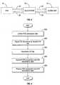
- Fig. 3shows a schematic block diagram of integrated POS and EAS data flow (also discussed in conjunction with Fig. 4 ) showing one particularly useful method for integrating POS and EAS data.
- a POS transactionoccurs at the POS station 6.
- This transactiontypically involves identifying the merchandise (e.g., scanning UPC code via attached scanner, inputting identifying information manually, etc.) in order to obtain the merchandise's pricing information, receiving payment (e.g., cash, credit card, bank check, etc.), as well as collecting and storing POS transaction data which includes payment information, any discounts or surcharges, as well as customer identity, cashier identity, etc.
- the POS transaction datais time stamped (e.g., with date and time of the transaction) and transmitted to the EAS deactivator 10 as represented by a data stream 20.
- step 302the POS station 6 signals the EAS deactivator 10 to disable the EAS tag attached to the merchandise (if present).
- the deactivation signalsare shown in a data stream 22.
- the data stream 22includes the identity of the merchandise that was purchased in step 300, this allows the EAS deactivator 10 to disable any EAS tags associated with the merchandise.
- the EAS deactivator 10deactivates any EAS tags found on the merchandise. This may be accomplished by contacting the detector 4 or a centralized EAS system computer (not shown) which may include a data base listing the EAS tag and detector 4 with which the EAS tag is registered. In conventional POS and EAS systems, POS station 6 and the EAS deactivator 10 are involved in bidirectional communication. After the deactivation, the EAS deactivator 10 transmits the deactivation data which includes the presence of an EAS tag, the deactivations performed, etc. back to the POS station 6, which would then compile the EAS deactivation data with the POS transaction data. As can be appreciated, this bidirectional communication tends to slow down and burden the POS system.
- step 306the EAS deactivator 10 transmits the POS transaction data in a data stream 24 and the EAS deactivation data in a data stream 26 to the alarm unit 14, thereby eliminating the need for bidirectional communication.
- the POS station 6may transmit POS transaction data directly to the alarm unit 14, which also eliminates the bidirectional communications between the POS station 6 and the EAS deactivator 10.
- the alarm unit 14stores and forwards the POS transaction and EAS deactivation data to the data processing unit 18 through the network 16.
- the data processing unit 18includes a database utilized by a data-mining package, which in step 308, correlates the number of merchandise items processed at the POS station 6 with the number of deactivations processed by the EAS deactivator 10.
- the correlated datamay include, for example, the following information, a cashier with an ID code 4321, logged into register No. 123, started transaction 0001, scanned item 12345678 on 05/10/05 at 10:25:42, two EAS deactivations occurred, ended the transaction 0000.
- this informationconsists of text characters, it may all be stored in a string where a delimiting character, such as a comma is used denote different data fields (e.g., 4321,0123,0001,12345678,05102005,102542,002,0000).
- a delimiting charactersuch as a comma
- different data fieldse.g., 4321,0123,0001,12345678,05102005,102542,002,0000.
- the correlated informationmay also be used for tag compliance reports, effectiveness of cashier personnel in POS transactions.
- data processingmay be accomplished at the alarm unit 14 and that the data processing unit 18 is described in the present disclosure to illustrate the different stages of the method.
- the data processing unit 18would compare the number of EAS tags that have POS station 6 attempted to deactivate with the number of EAS tags actually disabled by the EAS deactivator 10. If the numbers are not the same, it denotes that either an insufficient or extraneous number of disablements occurred. If there were an insufficient number of deactivations, the store 2 is indirectly affected, since the active EAS tags which were not properly deactivated would trigger an alarm causing unnecessary embarrassment and delay to the consumers when they would attempt to leave the store 2. This may reflect poorly on the image of the store 2. Conversely, if there were too many deactivations, then the EAS tags which were improperly deactivated, would allow for merchandise containing them to be removed from the store 2 without triggering the alarm 12.
- Such errorsmay be the result of human error (e.g., the cashier operating the POS station 6 improperly deactivates the EAS tag). This results in more direct harm to the store 2 since that merchandise can be easily stolen.
- Correlating EAS deactivation and POS transaction dataallows the managers of the store 2 to measure performance of sales personnel and take appropriate action (e.g., provide more training, transfer, termination, etc.).
- EAS deactivator 10By enabling the EAS deactivator 10 to function as one of or as the only data collection source, many additional benefits become readily available to the owner of the store 2, suppliers, and equipment manufacturers. More specifically, correlation of deactivation data with the scanning data provides a variety of valuable analytical tools.
- the systemallows for verification of tag compliance for retailers as well as manufacturers. For example, if all of a manufacturer's merchandise is tagged when it is supplied to a retail establishment, the system can correlate deactivation with POS information to determine the percentage of manufacturer's goods which are mistagged (e.g., label positioned too far from bar code). Moreover, employee misconduct is readily identifiable with the presently proposed system. For instance, internal theft by sales personnel can be identified by comparing the number of POS scans with the number of EAS deactivations. The system or the resulting data gathered therefrom may also be used to identify items which are improperly tagged or labeled (e.g., label positioned too far from bar code).
- Integrity of the EAS deactivator(s) or the POS terminals(s)may also be readily identified as part of the presently disclosed methods or systems. For example, if the number of deactivations is significantly lower or higher than the number of scans, the cause of the discrepancy may be attributable to malfunctioning deactivating equipment.
- the inventionintegrates the POS transaction and EAS deactivation data which allows for correlation of relevant information to determine the effectiveness of the personnel and/or equipment. Furthermore, the integration eliminates the need for bidirectional communication between the POS station and the EAS system wherein allows for more effective data processing and increased data throughput.
Landscapes
- Business, Economics & Management (AREA)
- Physics & Mathematics (AREA)
- Engineering & Computer Science (AREA)
- General Physics & Mathematics (AREA)
- Accounting & Taxation (AREA)
- Finance (AREA)
- Theoretical Computer Science (AREA)
- General Business, Economics & Management (AREA)
- Economics (AREA)
- Strategic Management (AREA)
- Electromagnetism (AREA)
- Marketing (AREA)
- Development Economics (AREA)
- Automation & Control Theory (AREA)
- Computer Security & Cryptography (AREA)
- Human Resources & Organizations (AREA)
- Operations Research (AREA)
- Quality & Reliability (AREA)
- Entrepreneurship & Innovation (AREA)
- Tourism & Hospitality (AREA)
- Technology Law (AREA)
- Burglar Alarm Systems (AREA)
- Cash Registers Or Receiving Machines (AREA)
- Management, Administration, Business Operations System, And Electronic Commerce (AREA)
Description
- Embodiments of the invention relate to point of sale (hereinafter "POS") and electronic article surveillance (hereinafter "EAS") systems and more specifically to a system and method for integrating data from POS and EAS systems by utilizing an alarm management unit.
- Current retail establishments utilize a plurality of electronic equipment within their outlets. Most important of these include a point of sale system and an electronic article surveillance system. POS systems perform retail transactions and include POS stations, such as cash registers, scanners, etc., and other equipment interconnected in a POS network. The POS stations, inter alia, identify merchandise, change inventory figures, (e.g., merchandise's price, quantity, sale reductions, etc.), and receive payment.
- EAS systems are detection systems that are configured to identify one or more of an EAS tags within a given detection region. EAS systems have many uses, but most often they are used as security systems for preventing shoplifting in stores. EAS systems are readily configurable for a variety of different purposes and typically are configured to make use of a number of different technologies.
- A typical EAS system includes an electronic detection unit, EAS tags, and a deactivator. Deactivation is commonly known to either deactivate tags attached or embedded in merchandise or detach tags from merchandise. The detection units form an EAS tag detection region and are usually placed in high traffic areas, such as entrances and exits of stores. The EAS tags have special characteristics and are specifically designed to be affixed to or embedded in merchandise or other objects sought to be protected. When an active EAS tag passes through the EAS tag detection region, the EAS system sounds an alarm, e.g., audio and/or visual alarm, to indicate the removal of the EAS tag from the proscribed area.
- Therefore, in order for a customer to leave with the purchased merchandise, the EAS tag attached thereto must be deactivated either by magnetically deactivating the tag or detaching the tag from the merchandise. Typically, EAS deactivators disable EAS tags mechanically or electronically and deactivation is accomplished during the retail transaction at the POS station. The EAS deactivator is connected to the POS station, which signals the EAS deactivator to disable the EAS tag once the merchandise has been paid for, allowing the merchandise to be removed from the store. Hence, during a retail transaction, both the POS transaction and the EAS deactivation in effect occur at the POS station. As a result, the POS station is involved in bidirectional communications with one or more EAS deactivators. In one direction, from POS station to the EAS deactivator, the POS station sends deactivation commands which are then forwarded to the EAS system to disable the EAS tag. In the opposite direction, from the EAS deactivator to the POS station, the EAS deactivator sends data concerning which and/or how many EAS tags have just been deactivated. Subsequently, the POS station network must also process and transport, both, the EAS deactivation data and the POS transaction data.
- This conventional arrangement drains extensive processing resources from the POS systems. In addition, this arrangement complicates the installation and modification of POS systems (e.g., networking equipment). Furthermore, the EAS deactivation data is processed separately from the POS transaction data, without correlating the two sources of information. Therefore, there is a need for a system which would alleviate the burden typically placed on the POS stations and networks which are routinely required to process the bidirectional POS and EAS data. Ideally, such a system would be configured to remove or modify bidirectional communication between the POS stations the EAS deactivators. The system would also correlate the two types of data to provide important statistical analysis for management concerns.
- In one particular useful embodiment, the present invention relates to a system for integrating information concerning point of sale (POS) transactions and electronic article surveillance (EAS) deactivations. The system includes a POS station configured to collect and transmit purchase data concerning purchased merchandise and a deactivation signal to disable EAS tag attached to the merchandise. The system also includes an EAS deactivator configured to receive the merchandise data and a deactivation signal from the POS station. The EAS deactivator is also configured to deactivate the EAS tag, collect data pertaining to deactivation of the EAS tag, and transmit the data pertaining to merchandise and deactivation. Also included, is an alarm management unit configured to receive, process and relay the purchase and deactivation data to a data processing unit, which analyzes the data and generates a report based on the data.
WO2004/077372 discloses an integrated electronic article surveillance (EAS) and point of sale (POS) system and method in which POS data and EAS alarm event data are compared. In this system, bidirectional communication is required between the POS station and the EAS deactivator.- In order to solve the problems associated with the prior art, the present invention provides a method for integrating information concerning point of sale (POS) transactions and electronic article surveillance (EAS) deactivations, the method comprises the steps of generating POS data by a POS station; transmitting deactivation signals from the POS station to an EAS deactivation device; generating EAS deactivation data by the EAS deactivation device; transmitting the EAS deactivation data and the POS data to an alarm management unit; and correlating the EAS deactivation data with the POS data to determine the effectiveness of a system comprising the POS station and the ESA deactivation device.
- The present invention also provides a system for integrating information concerning point of sale (POS) transactions and electronic article surveillance (EAS) deactivations, the system comprises a POS station arranged to generate POS data; an EAS deactivation device for receiving deactivation signals from the POS station and generating EAS deactivation data; an alarm management unit configured for receiving the EAS deactivation data and the POS data, data processing unit arranged to correlate the POS data and the EAS deactivation data to determine the effectiveness of a system comprising the POS station and the EAS deactivation device.
- Other aspects of the invention are set out in the accompanying claims.
- Various embodiments of a system and method for data logging of EAS tags are described herein with reference to the drawings wherein:
Fig. 1 is a schematic block diagram of a system for integrating POS and EAS data;Fig. 2 is an exemplary computing system for implementing the present disclosure;Fig. 3 is a schematic block diagram of integrated POS and EAS data flow; andFig. 4 is a flow diagram showing a method for integrating POS and EAS data.- Preferred embodiments of the present disclosure will be described hereinbelow with reference to the accompanying drawings. In the following description, well-known functions or constructions are not described in detail to avoid obscuring the present disclosure in unnecessary detail.
- A system and method for integrating POS transaction and EAS deactivation data is disclosed. In general, the herein disclosed system and method relate to POS station which processes merchandise and collects and stores related POS data. The data may include information relating to particular merchandise or whether the tag is present or absent from the merchandise. The POS station, in turn, transmits the POS data and deactivation signals to an EAS deactivator which disables EAS tags and relays POS data as well as EAS deactivation data to an alarm management unit. The alarm management unit thereafter transmits the data to a data processing unit for data integration and correlation.
- More particularly and with specific reference to the figures,
Fig. 1 shows a data integration system 1 for collecting EAS deactivation and POS transaction data. System 1 is typically deployed in a retail environment, e.g., a department store 2. Those skilled in the art will understand that the system 1 may be deployed in a plurality of settings where EAS systems and POS systems are usually installed. The store 2 may include a plurality of departments, e.g., men's apparel, women's apparel, electronics, etc. In addition, those departments may be subdivided into predetermined areas, e.g., shoes, fitting rooms, active wear, isles, etc. EAS tags are typically affixed to or embedded in the store's merchandise and/or the merchandise's packaging in order to prevent shoplifting. Those skilled in the art will appreciate that the EAS tags may be any EAS anti-theft device, such as a label or other more sophisticated devices having an outer casing and a plurality of metallic strips. - EAS systems typically operate using a transmitter and a receiver wherein the transmitter is placed on one side of the detection region and the receiver is placed on the opposite side of the detection region. In the case of a retail store, this detection region is usually defined at a checkout aisle or an exit. When an EAS tag enters the detection region, the EAS tag has a characteristic response to an exciter signal which is readily detectable. For example, the EAS tag may respond to the signal sent by the transmitter by using a simple semiconductor junction, a tuned circuit composed of an inductor and capacitor, soft magnetic strips or wires, or vibrating resonators. This characteristic response is subsequently detected by the receiver.
- The system 1 also includes a
detection unit 4, a point-of-sale ("POS")station 6, anEAS deactivator 10, analarm management unit 14, and analarm 12. Thedetection unit 4 includes a transmitter and a receiver which defines a predetermined EAS tag detection region. The detection region is preferably located around or in proximity to an exit 8 since placing thedetection unit 4 in a high-traffic area increases the chances of detecting shoplifted merchandise. The transmitter is configured to produces a predetermined exciter signal in the detection region. As a result, an active EAS tag (e.g., a non-deactivated or non-defeated EAS tag) passing through the detection region responds to the exciter signal which is recognized by thedetection unit 4. In that event, thedetection unit 4 sends a signal to thealarm 12 which generates an alarm, e.g., audio and/or visual alarm. POS station 6 may be any device adapted for performing POS transactions, e.g., a cash register and may include a display, a keypad, a printer for printing receipts, and/or a scanner for reading UPC codes.POS station 6 is typically connected to the EAS deactivator 10 in order to disable or defeat EAS tags attached to the merchandise.- More particularly, merchandise can only be removed from the store 2 if the EAS tags, which are usually attached to the merchandise or the packaging, are deactivated or defeated. The
EAS deactivator 10 is typically located near or at thePOS station 6 so that EAS tag deactivation occurs concurrently with the merchandise sale transaction. During the retail transaction,POS station 6 is configured to check out the merchandise, receive payment, and signal the EAS deactivator 10 to deactivate the EAS tag. Deactivation may be accomplished using any number of methods, such as physical removal of the EAS tag from the merchandise (e.g., an EAS tag attached to apparel) or electronic deactivation of the EAS tag, so that the EAS tag remains on the merchandise but will not respond to the exciter signal - (e.g., an EAS tag attached within a DVD case). It is also envisioned that the
EAS deactivator 10 may operate in a variety of modes. For instance, in a default mode theEAS deactivator 10 may be constantly on, where any EAS tags brought within the operational range thereof are deactivated. In another mode, theEAS deactivator 10 may be turned on to deactivate EAS tags only when required by the commands from thePOS station 6, while remaining in standby mode for the remainder of the time. - The
EAS deactivator 10 disables the EAS tag upon receiving the signal from thePOS station 6. In prior art systems, the EAS deactivator 10 transmits deactivation data (e.g., which tags have been deactivated) to thePOS station 6. In the present disclosure, the EAS deactivator 10 transmits the deactivation data to thealarm unit 14, which is also configured to receive POS transaction data fromPOS station 6 viaEAS deactivator 10 or detacher. As can be appreciated by the present disclosure, this eliminates bidirectional communications between the EAS deactivator 10 and thePOS station 6. - The
alarm unit 14, in addition to collecting EAS deactivation data and the POS transaction data, may be a terminal which controls the EAS system as well as safety equipment in the store 2 (e.g., fire alarm, anti-theft alarm, etc.). Thealarm unit 14 may also be configured as a data terminal or acomputing device 300 as shown inFig. 2 . It is to be understood that the present disclosure may be implemented in various forms of hardware, software, firmware, special purpose processors, or a combination thereof. In one embodiment, the present disclosure may be implemented in software or firmware as an application program tangibly embodied on thecomputing device 300. - The
computing device 300 may include one or more central processing units (CPU) 390, a random access memory (RAM) 391, a read only memory (ROM) 392 and input/output (I/O) interface(s) such as akeypad 393, cursor control device 394 (e.g., a mouse, touchscreen, etc.), adata storage device 398, anddisplay device 395. Furthermore, thecomputing device 300 may also include anetworking device 397 which provides wired or wireless connectivity to thenetwork 16. In addition, various other peripheral devices may be connected to thecomputing device 300 by various interfaces and bus structures, such as a parallel port, serial port or universal serial bus (USB) or wireless. Asystem bus 396 may be included which couples the various components and may be any of several types of bus structures including a memory bus or memory controller, a peripheral bus, and a local bus using any of a variety of different bus architectures. - The
computing device 300 may also be configured to include an operating system and micro instruction code. The various processes and functions described herein may either be part of the micro instruction code, firmware, or part of the application program (or a combination thereof) which is executed via the operating system. In addition, thecomputing device 300 may be designed to include software for displaying user input screens and recording user responses as discussed in more detail below. - It is to be further understood that because some of the constituent system components and method steps depicted in the accompanying figures may be implemented in software, the actual connections between the system components (or the process steps) may differ depending upon the manner in which the present disclosure is programmed. Given the teachings of the present disclosure provided herein, one of ordinary skill in the related art will be able to contemplate these and similar implementations or configurations of the present disclosure. The data logging method of the present disclosure may be used at several levels, including the operating system, the application level, or by the application components.
- The
alarm unit 14 is contemplated to connect to acommunications network 16 which allows thealarm unit 14 to transmit the collected POS transaction and EAS deactivation data to adata processing unit 18. Those skilled in the art will appreciate thatPOS station 6,EAS deactivator 10, andalarm unit 14 may be interconnected in a variety of ways, using wired and/or wireless interfaces. This allows for the interconnected devices to communicate with each other and share data. - The
network 16 may be a local area network (LAN), wide area network (WAN), the Internet and/or any known network that couples a plurality of computing devices to enable various modes of communication via network messages. For example, thenetwork 16 may be a corporate intranet including a single server and multiple personal computers housed within a single facility, or alternatively, multiple servers with multiple personal computers located in different geographic locations. - The
data processing unit 18 may be a central server which is part of a data storage facility for the store 2. In this instance, thedata processing unit 18 would be configured to process the POS transaction and EAS deactivation data fromalarm unit 14 and compile the data in a predetermined format. In addition, thedata processing unit 18 may be configured to have access to other types of data related to the store 2, (e.g., store occupancy, POS transactions, EAS tag deactivations, etc.) typically obtained from thePOS station 6 or other devices connected to thenetwork 16. Thedata processing unit 18 may combine such information with the data received from thealarm unit 14 to generate reports concerning shoplifting trends in the store 2 as discussed in more detail below. Fig. 3 shows a schematic block diagram of integrated POS and EAS data flow (also discussed in conjunction withFig. 4 ) showing one particularly useful method for integrating POS and EAS data. More particularly, instep 300, a POS transaction occurs at thePOS station 6. This transaction typically involves identifying the merchandise (e.g., scanning UPC code via attached scanner, inputting identifying information manually, etc.) in order to obtain the merchandise's pricing information, receiving payment (e.g., cash, credit card, bank check, etc.), as well as collecting and storing POS transaction data which includes payment information, any discounts or surcharges, as well as customer identity, cashier identity, etc. The POS transaction data is time stamped (e.g., with date and time of the transaction) and transmitted to the EAS deactivator 10 as represented by adata stream 20.- In
step 302, thePOS station 6 signals the EAS deactivator 10 to disable the EAS tag attached to the merchandise (if present). The deactivation signals are shown in adata stream 22. Thedata stream 22 includes the identity of the merchandise that was purchased instep 300, this allows the EAS deactivator 10 to disable any EAS tags associated with the merchandise. - In
step 304, theEAS deactivator 10 deactivates any EAS tags found on the merchandise. This may be accomplished by contacting thedetector 4 or a centralized EAS system computer (not shown) which may include a data base listing the EAS tag anddetector 4 with which the EAS tag is registered. In conventional POS and EAS systems,POS station 6 and the EAS deactivator 10 are involved in bidirectional communication. After the deactivation, the EAS deactivator 10 transmits the deactivation data which includes the presence of an EAS tag, the deactivations performed, etc. back to thePOS station 6, which would then compile the EAS deactivation data with the POS transaction data. As can be appreciated, this bidirectional communication tends to slow down and burden the POS system. - In according with the present disclosure, in
step 306 the EAS deactivator 10 transmits the POS transaction data in adata stream 24 and the EAS deactivation data in adata stream 26 to thealarm unit 14, thereby eliminating the need for bidirectional communication. Those skilled in the art will appreciate that thePOS station 6 may transmit POS transaction data directly to thealarm unit 14, which also eliminates the bidirectional communications between thePOS station 6 and theEAS deactivator 10. - In
step 306, thealarm unit 14 stores and forwards the POS transaction and EAS deactivation data to thedata processing unit 18 through thenetwork 16. Thedata processing unit 18 includes a database utilized by a data-mining package, which instep 308, correlates the number of merchandise items processed at thePOS station 6 with the number of deactivations processed by theEAS deactivator 10. The correlated data may include, for example, the following information, a cashier with an ID code 4321, logged into register No. 123, started transaction 0001, scanned item 12345678 on 05/10/05 at 10:25:42, two EAS deactivations occurred, ended the transaction 0000. Since this information consists of text characters, it may all be stored in a string where a delimiting character, such as a comma is used denote different data fields (e.g., 4321,0123,0001,12345678,05102005,102542,002,0000). Those skilled in the art will appreciate that other data structures may be used depending on the type of data collected. - The correlated information may also be used for tag compliance reports, effectiveness of cashier personnel in POS transactions. Those skilled in the art will appreciate that data processing may be accomplished at the
alarm unit 14 and that thedata processing unit 18 is described in the present disclosure to illustrate the different stages of the method. - In determining tag compliance, the
data processing unit 18 would compare the number of EAS tags that havePOS station 6 attempted to deactivate with the number of EAS tags actually disabled by theEAS deactivator 10. If the numbers are not the same, it denotes that either an insufficient or extraneous number of disablements occurred. If there were an insufficient number of deactivations, the store 2 is indirectly affected, since the active EAS tags which were not properly deactivated would trigger an alarm causing unnecessary embarrassment and delay to the consumers when they would attempt to leave the store 2. This may reflect poorly on the image of the store 2. Conversely, if there were too many deactivations, then the EAS tags which were improperly deactivated, would allow for merchandise containing them to be removed from the store 2 without triggering thealarm 12. Such errors may be the result of human error (e.g., the cashier operating thePOS station 6 improperly deactivates the EAS tag). This results in more direct harm to the store 2 since that merchandise can be easily stolen. Correlating EAS deactivation and POS transaction data allows the managers of the store 2 to measure performance of sales personnel and take appropriate action (e.g., provide more training, transfer, termination, etc.). - By enabling the EAS deactivator 10 to function as one of or as the only data collection source, many additional benefits become readily available to the owner of the store 2, suppliers, and equipment manufacturers. More specifically, correlation of deactivation data with the scanning data provides a variety of valuable analytical tools.
- The system allows for verification of tag compliance for retailers as well as manufacturers. For example, if all of a manufacturer's merchandise is tagged when it is supplied to a retail establishment, the system can correlate deactivation with POS information to determine the percentage of manufacturer's goods which are mistagged (e.g., label positioned too far from bar code). Moreover, employee misconduct is readily identifiable with the presently proposed system. For instance, internal theft by sales personnel can be identified by comparing the number of POS scans with the number of EAS deactivations. The system or the resulting data gathered therefrom may also be used to identify items which are improperly tagged or labeled (e.g., label positioned too far from bar code).
- Integrity of the EAS deactivator(s) or the POS terminals(s) may also be readily identified as part of the presently disclosed methods or systems. For example, if the number of deactivations is significantly lower or higher than the number of scans, the cause of the discrepancy may be attributable to malfunctioning deactivating equipment.
- The invention according to the present disclosure integrates the POS transaction and EAS deactivation data which allows for correlation of relevant information to determine the effectiveness of the personnel and/or equipment. Furthermore, the integration eliminates the need for bidirectional communication between the POS station and the EAS system wherein allows for more effective data processing and increased data throughput.
- While several embodiments of the disclosure have been shown in the drawings, it is not intended that the disclosure be limited thereto, as it is intended that the disclosure be as broad in scope as the art will allow and that the specification be read likewise. Therefore, the above description should not be construed as limiting, but merely as exemplifications of preferred embodiments. Those skilled in the art will envision other modifications.
Claims (15)
- A method for integrating information concerning point of sale (POS) transactions and electronic article surveillance (EAS) deactivations, the method comprising the steps of:generating (300) POS data by a POS station (6);transmitting (302) deactivation signals from the POS station (6) to an EAS deactivation device (10);generating (304) EAS deactivation data by the EAS deactivation device (10);transmitting (306) the EAS deactivation data and the POS data to an alarm management unit (14); andcorrelating (308) the EAS deactivation data with the POS data to determine the effectiveness of a system comprising the POS station and the ESA deactivation device (10).
- The method as claimed in claim 1 further comprising the steps of generating additional data at the alarm management unit (14) and combining the additional data with the POS data and the EAS deactivation data at the alarm management unit (14).
- A method as claimed in claim 1 or claim 2, wherein the step of correlating the data with the additional data determines at least one of effectiveness of employees, effectiveness of equipment, placement of EAS tags, and functionality of EAS tags.
- A system for integrating information concerning point of sale (POS) transactions and electronic article surveillance (EAS) deactivations, the system comprising:a POS station (6) arranged to generate POS data;an EAS deactivation device (10) for receiving deactivation signals from the POS station (6) and generating EAS deactivation data;an alarm management unit (14) configured for receiving the EAS deactivation data and the POS datadata processing unit (18; 14) arranged to correlate the POS data and the EAS deactivation data to determine the effectiveness of a system comprising the POS station and the EAS deactivation device (10).
- The system as claimed in claim 4 wherein the alarm management unit (14) generates additional data and combines this data with the POS data and the EAS deactivation data at the alarm management unit.
- The system as claimed in claim 4 or claim 5 wherein;
the POS station (6) is configured to collect and transmit the POS data, wherein the POS data is first data pertaining to purchased merchandise and has data relating to EAS deactivation;
the EAS deactivation device (10) is configured to receive a deactivation signal or a default condition from the POS station, the EAS deactivation device also being configured to deactivate at least one EAS tag, collect said EAS deactivation data which is second data pertaining to deactivation of the at least one EAS tag, and transmit the first and second data;
the alarm management unit (14) is configured to receive, process and relay the first and second data; and
the data processing unit (18; 14) is configured to receive and process the first and second data, the data processing unit also being configured to analyse the first and second data and generate third data pertaining to the first and second data. - A system as claimed in claim 6, wherein the data processing unit (18; 14) is arranged to correlate the first data with the second data to determine at least one of effectiveness of employees, effectiveness of equipment, placement of EAS tags, and functionality of EAS tags.
- A system as claimed in claim 6 or claim 7, wherein the data processing unit (18; 14) is arranged such that the third data correlates the first and second data to verify that a predetermined number of deactivations occurred.
- A system as claimed in claim 6 or claim 7, wherein the data processing unit (18; 14) is arranged such that the third data correlates the first and second data to determine effectiveness of a user at the POS station (6).
- A system as claimed in claim 6 or claim 7, wherein the data processing unit (18; 14) is arranged such that the third data correlates the first and second data to determine operability of the at least one EAS tag.
- A system as claimed in any one of claims 6 to 10, wherein the first data includes identifying information concerning a cashier, the POS station (6), the user at the POS station and the purchased merchandise.
- A system as claimed in any one of claims 6 to 11, wherein the data processing unit (18; 14) is arranged such that the third data correlates the first and second data to determine the possibility of internal theft.
- A system as claimed in any one of claims 6 to 11, wherein the data processing unit (18; 14) is arranged such that the third data correlates the first and second data to determine tagging compliance.
- A system as claimed in any one of claims 6 to 13, wherein the second data includes information relating to the number of deactivations occurred.
- A system as claimed in any one of claims 6 to 11, wherein the data processing unit (18; 14) is arranged such that the third data correlates the first and second data to derive diagnosis of integrity of the EAS deactivator (10).
Applications Claiming Priority (2)
| Application Number | Priority Date | Filing Date | Title |
|---|---|---|---|
| US63093904P | 2004-11-24 | 2004-11-24 | |
| PCT/US2005/042478WO2006058086A1 (en) | 2004-11-24 | 2005-11-22 | System and method for integrating point of sale and electronic article surveillance data |
Publications (2)
| Publication Number | Publication Date |
|---|---|
| EP1817758A1 EP1817758A1 (en) | 2007-08-15 |
| EP1817758B1true EP1817758B1 (en) | 2016-01-20 |
Family
ID=35985195
Family Applications (1)
| Application Number | Title | Priority Date | Filing Date |
|---|---|---|---|
| EP05849493.1AActiveEP1817758B1 (en) | 2004-11-24 | 2005-11-22 | System and method for integrating point of sale and electronic article surveillance data |
Country Status (10)
| Country | Link |
|---|---|
| US (1) | US20090198529A1 (en) |
| EP (1) | EP1817758B1 (en) |
| JP (1) | JP2008522286A (en) |
| KR (1) | KR20070086568A (en) |
| CN (1) | CN100595804C (en) |
| AU (1) | AU2005309628A1 (en) |
| CA (1) | CA2588718A1 (en) |
| ES (1) | ES2566489T3 (en) |
| MX (1) | MX2007006209A (en) |
| WO (1) | WO2006058086A1 (en) |
Families Citing this family (18)
| Publication number | Priority date | Publication date | Assignee | Title |
|---|---|---|---|---|
| US7527198B2 (en)* | 2002-03-18 | 2009-05-05 | Datalogic Scanning, Inc. | Operation monitoring and enhanced host communications in systems employing electronic article surveillance and RFID tags |
| US20080094219A1 (en)* | 2006-10-18 | 2008-04-24 | Ac Technologies S.A. | Privacy Protection Cleanup Shop Station and Devices |
| US20080246611A1 (en)* | 2007-04-04 | 2008-10-09 | John King | Method and apparatus for detecting the presence of rfid devices and modifying the same |
| US20090237219A1 (en)* | 2008-03-21 | 2009-09-24 | Berlin Bradley M | Security apparatus, system and method of using same |
| KR101041217B1 (en)* | 2008-12-08 | 2011-06-13 | 학교법인 동의학원 | RFS-based EAS system |
| US7973663B2 (en)* | 2009-01-07 | 2011-07-05 | Sensomatic Electronics, LLC | Electronic article surveillance deactivator using visual pattern recognition system for triggering |
| MX2012003457A (en) | 2009-09-21 | 2012-08-03 | Checkpoint Systems Inc | Retail product tracking system, method, and apparatus. |
| US8508367B2 (en) | 2009-09-21 | 2013-08-13 | Checkpoint Systems, Inc. | Configurable monitoring device |
| WO2011041688A1 (en)* | 2009-10-02 | 2011-04-07 | Checkpoint Systems, Inc. | Key device for monitoring systems |
| US8942992B1 (en)* | 2010-05-20 | 2015-01-27 | Sprint Communications Company L.P. | Dynamic promotion code insertion in contactless payment transaction |
| US20120280040A1 (en)* | 2011-05-06 | 2012-11-08 | Verizon Patent And Licensing Inc. | Wireless-based checkout and loss prevention |
| US10453055B2 (en)* | 2012-02-12 | 2019-10-22 | Cytherean Mandelbrot LLC | Method for secure electronic tender |
| US20130304553A1 (en) | 2012-05-09 | 2013-11-14 | Google Inc. | Point of sale offer redemptions |
| US10127745B2 (en) | 2014-12-29 | 2018-11-13 | Invue Security Products Inc. | Merchandise display security systems and methods |
| US9830791B2 (en)* | 2015-05-27 | 2017-11-28 | Tyco Fire & Security Gmbh | Self-detachable RFID tags |
| US11461810B2 (en) | 2016-01-29 | 2022-10-04 | Sensormatic Electronics, LLC | Adaptive video advertising using EAS pedestals or similar structure |
| US10853841B2 (en)* | 2016-01-29 | 2020-12-01 | Sensormatic Electronics, LLC | Adaptive video advertising using EAS pedestals or similar structure |
| DE102020201865A1 (en)* | 2020-02-14 | 2021-08-19 | Rapitag Gmbh | ANTI-THEFT SECURITY SYSTEM AND METHOD FOR OPERATING A ANTI-THEFT SECURITY SYSTEM |
Family Cites Families (3)
| Publication number | Priority date | Publication date | Assignee | Title |
|---|---|---|---|---|
| US6169483B1 (en)* | 1999-05-04 | 2001-01-02 | Sensormatic Electronics Corporation | Self-checkout/self-check-in RFID and electronics article surveillance system |
| US7527198B2 (en)* | 2002-03-18 | 2009-05-05 | Datalogic Scanning, Inc. | Operation monitoring and enhanced host communications in systems employing electronic article surveillance and RFID tags |
| EP1595233A4 (en)* | 2003-02-21 | 2007-01-03 | Sensormatic Electronics Corp | Integrated electronic article surveillance (eas) and point of sale (pos) system and method |
- 2005
- 2005-11-22CACA002588718Apatent/CA2588718A1/ennot_activeAbandoned
- 2005-11-22JPJP2007543446Apatent/JP2008522286A/enactivePending
- 2005-11-22USUS11/791,094patent/US20090198529A1/ennot_activeAbandoned
- 2005-11-22ESES05849493.1Tpatent/ES2566489T3/enactiveActive
- 2005-11-22MXMX2007006209Apatent/MX2007006209A/enactiveIP Right Grant
- 2005-11-22EPEP05849493.1Apatent/EP1817758B1/enactiveActive
- 2005-11-22CNCN200580046062Apatent/CN100595804C/enactiveActive
- 2005-11-22WOPCT/US2005/042478patent/WO2006058086A1/enactiveApplication Filing
- 2005-11-22AUAU2005309628Apatent/AU2005309628A1/ennot_activeAbandoned
- 2005-11-22KRKR1020077014260Apatent/KR20070086568A/ennot_activeCeased
Also Published As
| Publication number | Publication date |
|---|---|
| CN100595804C (en) | 2010-03-24 |
| WO2006058086A1 (en) | 2006-06-01 |
| AU2005309628A1 (en) | 2006-06-01 |
| US20090198529A1 (en) | 2009-08-06 |
| CA2588718A1 (en) | 2006-06-01 |
| ES2566489T3 (en) | 2016-04-13 |
| MX2007006209A (en) | 2008-02-19 |
| JP2008522286A (en) | 2008-06-26 |
| HK1113519A1 (en) | 2008-10-03 |
| KR20070086568A (en) | 2007-08-27 |
| EP1817758A1 (en) | 2007-08-15 |
| CN101099184A (en) | 2008-01-02 |
Similar Documents
| Publication | Publication Date | Title |
|---|---|---|
| EP1817758B1 (en) | System and method for integrating point of sale and electronic article surveillance data | |
| JP5114213B2 (en) | Alarm investigation using RFID | |
| AU2004205136B2 (en) | Intergrated electronic article surveillance (EAS) and point of sale (POS) system and method | |
| EP1768073B1 (en) | Real-time system for monitoring theft protection | |
| KR101541024B1 (en) | Electronic article surveillance deactivator with multiple label detection and method thereof | |
| US8047434B2 (en) | Known loss data logging | |
| HK1113519B (en) | System and method for integrating point of sale and electronic article surveillance data | |
| AU2013251246B2 (en) | Integrated electronic article surveillance (EAS) and point of sale (POS) system and method | |
| HK1116282B (en) | Method and system of alarm investigation using rfid |
Legal Events
| Date | Code | Title | Description |
|---|---|---|---|
| PUAI | Public reference made under article 153(3) epc to a published international application that has entered the european phase | Free format text:ORIGINAL CODE: 0009012 | |
| 17P | Request for examination filed | Effective date:20070608 | |
| AK | Designated contracting states | Kind code of ref document:A1 Designated state(s):AT BE BG CH CY CZ DE DK EE ES FI FR GB GR HU IE IS IT LI LT LU LV MC NL PL PT RO SE SI SK TR | |
| DAX | Request for extension of the european patent (deleted) | ||
| 17Q | First examination report despatched | Effective date:20081211 | |
| RAP1 | Party data changed (applicant data changed or rights of an application transferred) | Owner name:SENSORMATIC ELECTRONICS, LLC | |
| RAP1 | Party data changed (applicant data changed or rights of an application transferred) | Owner name:SENSORMATIC ELECTRONICS, LLC | |
| REG | Reference to a national code | Ref country code:DE Ref legal event code:R079 Ref document number:602005048371 Country of ref document:DE Free format text:PREVIOUS MAIN CLASS: G08B0013240000 Ipc:G06Q0010080000 | |
| GRAP | Despatch of communication of intention to grant a patent | Free format text:ORIGINAL CODE: EPIDOSNIGR1 | |
| RIC1 | Information provided on ipc code assigned before grant | Ipc:G06Q 10/08 20120101AFI20150605BHEP Ipc:G06Q 40/00 20120101ALI20150605BHEP Ipc:G06Q 20/20 20120101ALI20150605BHEP | |
| INTG | Intention to grant announced | Effective date:20150622 | |
| GRAS | Grant fee paid | Free format text:ORIGINAL CODE: EPIDOSNIGR3 | |
| RAP1 | Party data changed (applicant data changed or rights of an application transferred) | Owner name:TYCO FIRE & SECURITY GMBH | |
| GRAA | (expected) grant | Free format text:ORIGINAL CODE: 0009210 | |
| AK | Designated contracting states | Kind code of ref document:B1 Designated state(s):AT BE BG CH CY CZ DE DK EE ES FI FR GB GR HU IE IS IT LI LT LU LV MC NL PL PT RO SE SI SK TR | |
| REG | Reference to a national code | Ref country code:GB Ref legal event code:FG4D | |
| REG | Reference to a national code | Ref country code:CH Ref legal event code:EP | |
| REG | Reference to a national code | Ref country code:IE Ref legal event code:FG4D | |
| REG | Reference to a national code | Ref country code:AT Ref legal event code:REF Ref document number:772039 Country of ref document:AT Kind code of ref document:T Effective date:20160215 | |
| REG | Reference to a national code | Ref country code:DE Ref legal event code:R096 Ref document number:602005048371 Country of ref document:DE | |
| REG | Reference to a national code | Ref country code:ES Ref legal event code:FG2A Ref document number:2566489 Country of ref document:ES Kind code of ref document:T3 Effective date:20160413 | |
| REG | Reference to a national code | Ref country code:LT Ref legal event code:MG4D Ref country code:NL Ref legal event code:MP Effective date:20160120 | |
| REG | Reference to a national code | Ref country code:AT Ref legal event code:MK05 Ref document number:772039 Country of ref document:AT Kind code of ref document:T Effective date:20160120 | |
| PG25 | Lapsed in a contracting state [announced via postgrant information from national office to epo] | Ref country code:NL Free format text:LAPSE BECAUSE OF FAILURE TO SUBMIT A TRANSLATION OF THE DESCRIPTION OR TO PAY THE FEE WITHIN THE PRESCRIBED TIME-LIMIT Effective date:20160120 | |
| PG25 | Lapsed in a contracting state [announced via postgrant information from national office to epo] | Ref country code:FI Free format text:LAPSE BECAUSE OF FAILURE TO SUBMIT A TRANSLATION OF THE DESCRIPTION OR TO PAY THE FEE WITHIN THE PRESCRIBED TIME-LIMIT Effective date:20160120 Ref country code:IT Free format text:LAPSE BECAUSE OF FAILURE TO SUBMIT A TRANSLATION OF THE DESCRIPTION OR TO PAY THE FEE WITHIN THE PRESCRIBED TIME-LIMIT Effective date:20160120 Ref country code:GR Free format text:LAPSE BECAUSE OF FAILURE TO SUBMIT A TRANSLATION OF THE DESCRIPTION OR TO PAY THE FEE WITHIN THE PRESCRIBED TIME-LIMIT Effective date:20160421 | |
| PG25 | Lapsed in a contracting state [announced via postgrant information from national office to epo] | Ref country code:LT Free format text:LAPSE BECAUSE OF FAILURE TO SUBMIT A TRANSLATION OF THE DESCRIPTION OR TO PAY THE FEE WITHIN THE PRESCRIBED TIME-LIMIT Effective date:20160120 Ref country code:IS Free format text:LAPSE BECAUSE OF FAILURE TO SUBMIT A TRANSLATION OF THE DESCRIPTION OR TO PAY THE FEE WITHIN THE PRESCRIBED TIME-LIMIT Effective date:20160520 Ref country code:PT Free format text:LAPSE BECAUSE OF FAILURE TO SUBMIT A TRANSLATION OF THE DESCRIPTION OR TO PAY THE FEE WITHIN THE PRESCRIBED TIME-LIMIT Effective date:20160520 Ref country code:PL Free format text:LAPSE BECAUSE OF FAILURE TO SUBMIT A TRANSLATION OF THE DESCRIPTION OR TO PAY THE FEE WITHIN THE PRESCRIBED TIME-LIMIT Effective date:20160120 Ref country code:LV Free format text:LAPSE BECAUSE OF FAILURE TO SUBMIT A TRANSLATION OF THE DESCRIPTION OR TO PAY THE FEE WITHIN THE PRESCRIBED TIME-LIMIT Effective date:20160120 Ref country code:AT Free format text:LAPSE BECAUSE OF FAILURE TO SUBMIT A TRANSLATION OF THE DESCRIPTION OR TO PAY THE FEE WITHIN THE PRESCRIBED TIME-LIMIT Effective date:20160120 Ref country code:SE Free format text:LAPSE BECAUSE OF FAILURE TO SUBMIT A TRANSLATION OF THE DESCRIPTION OR TO PAY THE FEE WITHIN THE PRESCRIBED TIME-LIMIT Effective date:20160120 | |
| REG | Reference to a national code | Ref country code:DE Ref legal event code:R097 Ref document number:602005048371 Country of ref document:DE | |
| PG25 | Lapsed in a contracting state [announced via postgrant information from national office to epo] | Ref country code:EE Free format text:LAPSE BECAUSE OF FAILURE TO SUBMIT A TRANSLATION OF THE DESCRIPTION OR TO PAY THE FEE WITHIN THE PRESCRIBED TIME-LIMIT Effective date:20160120 Ref country code:DK Free format text:LAPSE BECAUSE OF FAILURE TO SUBMIT A TRANSLATION OF THE DESCRIPTION OR TO PAY THE FEE WITHIN THE PRESCRIBED TIME-LIMIT Effective date:20160120 | |
| REG | Reference to a national code | Ref country code:FR Ref legal event code:PLFP Year of fee payment:12 | |
| PLBE | No opposition filed within time limit | Free format text:ORIGINAL CODE: 0009261 | |
| STAA | Information on the status of an ep patent application or granted ep patent | Free format text:STATUS: NO OPPOSITION FILED WITHIN TIME LIMIT | |
| PG25 | Lapsed in a contracting state [announced via postgrant information from national office to epo] | Ref country code:CZ Free format text:LAPSE BECAUSE OF FAILURE TO SUBMIT A TRANSLATION OF THE DESCRIPTION OR TO PAY THE FEE WITHIN THE PRESCRIBED TIME-LIMIT Effective date:20160120 Ref country code:RO Free format text:LAPSE BECAUSE OF FAILURE TO SUBMIT A TRANSLATION OF THE DESCRIPTION OR TO PAY THE FEE WITHIN THE PRESCRIBED TIME-LIMIT Effective date:20160120 Ref country code:SK Free format text:LAPSE BECAUSE OF FAILURE TO SUBMIT A TRANSLATION OF THE DESCRIPTION OR TO PAY THE FEE WITHIN THE PRESCRIBED TIME-LIMIT Effective date:20160120 | |
| 26N | No opposition filed | Effective date:20161021 | |
| PG25 | Lapsed in a contracting state [announced via postgrant information from national office to epo] | Ref country code:BE Free format text:LAPSE BECAUSE OF FAILURE TO SUBMIT A TRANSLATION OF THE DESCRIPTION OR TO PAY THE FEE WITHIN THE PRESCRIBED TIME-LIMIT Effective date:20160120 | |
| PG25 | Lapsed in a contracting state [announced via postgrant information from national office to epo] | Ref country code:SI Free format text:LAPSE BECAUSE OF FAILURE TO SUBMIT A TRANSLATION OF THE DESCRIPTION OR TO PAY THE FEE WITHIN THE PRESCRIBED TIME-LIMIT Effective date:20160120 Ref country code:BG Free format text:LAPSE BECAUSE OF FAILURE TO SUBMIT A TRANSLATION OF THE DESCRIPTION OR TO PAY THE FEE WITHIN THE PRESCRIBED TIME-LIMIT Effective date:20160420 | |
| REG | Reference to a national code | Ref country code:CH Ref legal event code:PL | |
| PG25 | Lapsed in a contracting state [announced via postgrant information from national office to epo] | Ref country code:LI Free format text:LAPSE BECAUSE OF NON-PAYMENT OF DUE FEES Effective date:20161130 Ref country code:CH Free format text:LAPSE BECAUSE OF NON-PAYMENT OF DUE FEES Effective date:20161130 | |
| REG | Reference to a national code | Ref country code:IE Ref legal event code:MM4A | |
| PG25 | Lapsed in a contracting state [announced via postgrant information from national office to epo] | Ref country code:LU Free format text:LAPSE BECAUSE OF NON-PAYMENT OF DUE FEES Effective date:20161130 | |
| REG | Reference to a national code | Ref country code:FR Ref legal event code:PLFP Year of fee payment:13 | |
| PG25 | Lapsed in a contracting state [announced via postgrant information from national office to epo] | Ref country code:IE Free format text:LAPSE BECAUSE OF NON-PAYMENT OF DUE FEES Effective date:20161122 | |
| PG25 | Lapsed in a contracting state [announced via postgrant information from national office to epo] | Ref country code:HU Free format text:LAPSE BECAUSE OF FAILURE TO SUBMIT A TRANSLATION OF THE DESCRIPTION OR TO PAY THE FEE WITHIN THE PRESCRIBED TIME-LIMIT; INVALID AB INITIO Effective date:20051122 Ref country code:CY Free format text:LAPSE BECAUSE OF FAILURE TO SUBMIT A TRANSLATION OF THE DESCRIPTION OR TO PAY THE FEE WITHIN THE PRESCRIBED TIME-LIMIT Effective date:20160120 | |
| PG25 | Lapsed in a contracting state [announced via postgrant information from national office to epo] | Ref country code:TR Free format text:LAPSE BECAUSE OF FAILURE TO SUBMIT A TRANSLATION OF THE DESCRIPTION OR TO PAY THE FEE WITHIN THE PRESCRIBED TIME-LIMIT Effective date:20160120 Ref country code:MC Free format text:LAPSE BECAUSE OF FAILURE TO SUBMIT A TRANSLATION OF THE DESCRIPTION OR TO PAY THE FEE WITHIN THE PRESCRIBED TIME-LIMIT Effective date:20160120 | |
| REG | Reference to a national code | Ref country code:ES Ref legal event code:PC2A Owner name:SENSORMATIC ELECTRONICS, LLC Effective date:20190201 | |
| REG | Reference to a national code | Ref country code:GB Ref legal event code:732E Free format text:REGISTERED BETWEEN 20191205 AND 20191211 | |
| PGFP | Annual fee paid to national office [announced via postgrant information from national office to epo] | Ref country code:DE Payment date:20241128 Year of fee payment:20 | |
| PGFP | Annual fee paid to national office [announced via postgrant information from national office to epo] | Ref country code:GB Payment date:20241126 Year of fee payment:20 | |
| PGFP | Annual fee paid to national office [announced via postgrant information from national office to epo] | Ref country code:FR Payment date:20241126 Year of fee payment:20 | |
| PGFP | Annual fee paid to national office [announced via postgrant information from national office to epo] | Ref country code:ES Payment date:20241216 Year of fee payment:20 |