EP1816970B1 - Device for the resection and/or ablation or organic tissue by means of a high frequency current - Google Patents
Device for the resection and/or ablation or organic tissue by means of a high frequency currentDownload PDFInfo
- Publication number
- EP1816970B1 EP1816970B1EP05802292AEP05802292AEP1816970B1EP 1816970 B1EP1816970 B1EP 1816970B1EP 05802292 AEP05802292 AEP 05802292AEP 05802292 AEP05802292 AEP 05802292AEP 1816970 B1EP1816970 B1EP 1816970B1
- Authority
- EP
- European Patent Office
- Prior art keywords
- helix
- tube
- loop
- tissue
- coil
- Prior art date
- Legal status (The legal status is an assumption and is not a legal conclusion. Google has not performed a legal analysis and makes no representation as to the accuracy of the status listed.)
- Ceased
Links
Images


Classifications
- A—HUMAN NECESSITIES
- A61—MEDICAL OR VETERINARY SCIENCE; HYGIENE
- A61B—DIAGNOSIS; SURGERY; IDENTIFICATION
- A61B18/00—Surgical instruments, devices or methods for transferring non-mechanical forms of energy to or from the body
- A61B18/04—Surgical instruments, devices or methods for transferring non-mechanical forms of energy to or from the body by heating
- A61B18/12—Surgical instruments, devices or methods for transferring non-mechanical forms of energy to or from the body by heating by passing a current through the tissue to be heated, e.g. high-frequency current
- A61B18/14—Probes or electrodes therefor
- A—HUMAN NECESSITIES
- A61—MEDICAL OR VETERINARY SCIENCE; HYGIENE
- A61B—DIAGNOSIS; SURGERY; IDENTIFICATION
- A61B17/00—Surgical instruments, devices or methods
- A61B17/32—Surgical cutting instruments
- A61B17/320016—Endoscopic cutting instruments, e.g. arthroscopes, resectoscopes
- A61B17/32002—Endoscopic cutting instruments, e.g. arthroscopes, resectoscopes with continuously rotating, oscillating or reciprocating cutting instruments
- A—HUMAN NECESSITIES
- A61—MEDICAL OR VETERINARY SCIENCE; HYGIENE
- A61B—DIAGNOSIS; SURGERY; IDENTIFICATION
- A61B18/00—Surgical instruments, devices or methods for transferring non-mechanical forms of energy to or from the body
- A61B18/04—Surgical instruments, devices or methods for transferring non-mechanical forms of energy to or from the body by heating
- A61B18/12—Surgical instruments, devices or methods for transferring non-mechanical forms of energy to or from the body by heating by passing a current through the tissue to be heated, e.g. high-frequency current
- A61B18/14—Probes or electrodes therefor
- A61B18/149—Probes or electrodes therefor bow shaped or with rotatable body at cantilever end, e.g. for resectoscopes, or coagulating rollers
- A—HUMAN NECESSITIES
- A61—MEDICAL OR VETERINARY SCIENCE; HYGIENE
- A61B—DIAGNOSIS; SURGERY; IDENTIFICATION
- A61B18/00—Surgical instruments, devices or methods for transferring non-mechanical forms of energy to or from the body
- A61B2018/00053—Mechanical features of the instrument of device
- A61B2018/00184—Moving parts
- A61B2018/00202—Moving parts rotating
- A61B2018/00208—Moving parts rotating actively driven, e.g. by a motor
- A—HUMAN NECESSITIES
- A61—MEDICAL OR VETERINARY SCIENCE; HYGIENE
- A61B—DIAGNOSIS; SURGERY; IDENTIFICATION
- A61B18/00—Surgical instruments, devices or methods for transferring non-mechanical forms of energy to or from the body
- A61B2018/00982—Surgical instruments, devices or methods for transferring non-mechanical forms of energy to or from the body combined with or comprising means for visual or photographic inspections inside the body, e.g. endoscopes
- A—HUMAN NECESSITIES
- A61—MEDICAL OR VETERINARY SCIENCE; HYGIENE
- A61B—DIAGNOSIS; SURGERY; IDENTIFICATION
- A61B18/00—Surgical instruments, devices or methods for transferring non-mechanical forms of energy to or from the body
- A61B18/04—Surgical instruments, devices or methods for transferring non-mechanical forms of energy to or from the body by heating
- A61B18/12—Surgical instruments, devices or methods for transferring non-mechanical forms of energy to or from the body by heating by passing a current through the tissue to be heated, e.g. high-frequency current
- A61B18/14—Probes or electrodes therefor
- A61B2018/1405—Electrodes having a specific shape
- A61B2018/1407—Loop
- A—HUMAN NECESSITIES
- A61—MEDICAL OR VETERINARY SCIENCE; HYGIENE
- A61B—DIAGNOSIS; SURGERY; IDENTIFICATION
- A61B18/00—Surgical instruments, devices or methods for transferring non-mechanical forms of energy to or from the body
- A61B18/18—Surgical instruments, devices or methods for transferring non-mechanical forms of energy to or from the body by applying electromagnetic radiation, e.g. microwaves
- A61B18/1815—Surgical instruments, devices or methods for transferring non-mechanical forms of energy to or from the body by applying electromagnetic radiation, e.g. microwaves using microwaves
- A61B2018/1861—Surgical instruments, devices or methods for transferring non-mechanical forms of energy to or from the body by applying electromagnetic radiation, e.g. microwaves using microwaves with an instrument inserted into a body lumen or cavity, e.g. a catheter
Definitions
- the inventionrelates to a device for resection and / or ablation of organic tissue by means of high-frequency current, with at least one helix, wherein the helix is set in rotation about the longitudinal axis of the helix.
- Such a deviceis off WO 98/24372 A1 known.
- the micromill cellhas a cutting head having a tubular member in which a blade is disposed. A distal edge of the tubular member has a sharpened bevel. The blade is located immediately below or flush with the distal edge of the tubular member.
- the bladepreferably consists of one turn of a double helix and is designed to cut tissue which projects into the tubular element.
- the cutting headis secured to a drive shaft so that the helix of the blade can be rotated in a direction suitable for urging severed tissue into the interior of the drive shaft.
- the helical blademay extend to the proximal end of the shaft. In this case, the helical structure acts as an Archimedes screw, so that the rotation of the helix carries severed tissue proximally.
- the tubular element of the cutting headcan be made of an electrically conductive material and applied with HF voltage.
- Resection or ablation of organic structuresis carried out, for example, in hysteroscopy for the removal of fibroids, polyps and tissue of the endometrium and in urology for the removal of prostatic adenomas.
- Such resections or ablations of organic structuresare conventionally carried out by means of a resection instrument which has an electrically conductive and high-frequency current-loadable metal loop at the distal end.
- the loopis subjected to monopolar or bipolar RF voltage and manually moved by the operating physician to effect a cut to sever tissue in the direction of the longitudinal axis of the resection instrument, in a reciprocating manner Motion or in one direction only.
- the loop subjected to high-frequency currentbehaves like an electric scalpel.
- the loopallows in this way the separation of tissue pieces of the same diameter. Stopping bleeding associated with tissue removal may also be accomplished with the same loop after the tissue piece has been detached from the loop. The detached tissue pieces must then be removed from the treatment area in a mechanical manner at another time.
- a disadvantage of such conventional devices for resecting tissue by means of high-frequency currentis that due to the fact that the separated tissue pieces must be removed after separation by means of another instrument, such as a forceps, from the treatment area, the duration of the procedure on the patient increases is. The increased duration of the procedure is due to the required multiple instrument changes between the resecting instrument for the process of separating tissue and the removal instrument for the process of removing the separated tissue.
- Another disadvantage of the conventional devicesis the limitation of their use to the particular indication for which they are intended. Furthermore, visual inspection is difficult with these devices.
- WO 95/30377 A1discloses a surgical instrument for treating the prostate.
- the instrumenthas a tube containing channels for observation, illumination, irrigation fluid delivery, and fluid and cut tissue removal.
- the tubecontains a motor-driven shaft, the shaft carrying a knife at its distal end.
- the knifewhich is in the form of a loop, are set in rotation.
- FR 2 645 008discloses a surgical instrument for resecting tissue having a loop at the distal end of a rotatable shaft which is located at the distal end of a rotatable shaft distal end protrudes transversely from the shaft. Through the shaft, the loop can be rotated to cut tissue.
- the inventionhas the object of developing a device of the type mentioned in such a way that the disadvantages described above are avoided, that in particular the duration of a resection intervention can be reduced.
- this objectis achieved with respect to the device mentioned above in that distally from the at least one coil a loop is arranged, the coil and the loop can be acted upon by high frequency voltage, and that the arrangement of loop and coil about the longitudinal axis of the coil in rotation is displaceable.
- Another effect of the rotating coilis now advantageously that separated tissue can be taken into the interior of the coil, and wherein this separated tissue entering the interior of the coil can be transported by the rotation of the at least one coil in the direction of the proximal end of the device ,
- the device according to the inventionit is thus possible without instrument change to carry out a resection of organic tissue without interruption while at the same time removing the separated tissue and quenching bleeding.
- the device according to the inventionthus makes it possible to reduce the duration of an intervention in comparison to the conventional devices.
- the deviceis suitable for monopolar, but also for bipolar embodiments.
- the helixis designed as a double helix or multiple helix.
- Double helixor “multiple helix” here means that the helix is composed of two or more helical and preferably cylindrical structures.
- the design of the at least one helix as a double helix or multiple helixleads on the one hand to a higher torsional stiffness of the helix when resecting firmer tissue, in particular if the helix is long in the longitudinal direction, and, moreover, in this way the effect of entrainment of severed tissue to the proximal end can be improved become.
- the at least one helixis preferably designed such that it allows removal of tissue located laterally from the helix.
- the helixis preferably designed so that it allows a transport of separated tissue to the proximal.
- the helixis partially surrounded by a tube and at least partially firmly connected thereto, wherein a distal portion of the helix protrudes from a distal opening of the tube from the tube.
- the tubeensures an even greater torsional rigidity of the helix.
- the distal portion of the helix projecting from the distal opening of the tubeis then the actively cutting and at least the portion that is exposed to high frequency current.
- the solid Connection between helix and tubecan be made for example by gluing.
- the tubeis set in rotation by means of a motor.
- the helixis not firmly connected to the tube, but is freely rotatable relative to the tube.
- the tubeis preferably fixed, and the helix is rotated by means of the motor.
- the helixextends at least approximately over the entire length of the tube.
- the helixextends only over a partial length of the tube.
- This measureis particularly advantageous with the above-mentioned measure, according to which only the helix can be set into rotation, since the replacement of the helix is easier to accomplish.
- Bladescan then preferably be used as the current supply for the coil, in the case of a double helix correspondingly two blades which extend from the proximal-side HF connection to approximately the proximal end of the helix through the tube 16 and are contacted there with the helix.
- the bladescan be connected via sliding contacts, in particular slip rings, with the RF connector, since the blades must rotate with the coil.
- the bladescan remain in the tube with a replaceable configuration of the helix.
- the easier interchangeability of the loop and the coil without interchangeability of the tubehas the further advantage that for different applications quickly a replacement loop with spare coil can be installed in the device, without requiring a major disassembly of the device is required.
- the section of the coil extending in the tubeis electrically insulated. It is advantageous that the separated tissue transported inside the helix through the tube does not adhere to the helix due to heating.
- the tubeis electrically insulated.
- the protruding from the pipe section of the coilis preferably not electrically insulated.
- the protruding from the pipe section of the helixis formed of a rigid wire or formed as a cutting blade with inwardly directed cutting edge.
- the configuration of the helix as a cutting blade with an inwardly directed cutting edge in its section protruding from the tubeis suitable for further morcellizing the severed tissue and favoring the transport of the separated tissue into the interior of the at least one helix.
- the section of the helix extending in the tubewhich preferably has a variable width, has an inwardly directed cutting edge.
- the inwardly directed cutting edgehas the advantage that the transport of separated tissue pieces entering or entering the tube is further favored proximally.
- the distal opening of the tubemay have a blunt or cutting edge.
- the tubepreferably has a diameter in the range of about 3 to about 6.5 mm, but also outside this range diameters may be considered depending on the application.
- the loop at the distal end of the deviceis preferably semicircular, and preferably has a diameter of 4 to 7 mm.
- the loopis further preferably formed of a rigid electrically conductive wire or formed as a cutting blade, in the latter case, the cutting edge is directed inwards.
- the plane of the loopis inclined relative to the longitudinal axis, preferably slightly inclined, such that tissue separated from the loop is oriented toward the interior of the coil.
- tissue severed from the sling frontallycan more easily enter the interior of the coil for the purpose of transporting proximally.
- the rotational speed of the at least one coil and the loopin a range of 0 to 1000 revolutions per minute, preferably continuously, adjustable.
- fixed rotational speedsare preset, for example of 20 revolutions per minute, 300 and 800 revolutions per minute, which can then be set rapidly, for example by means of a corresponding actuating button.
- a fine adjustmentfor example in two areas, for example in a range of 0 to 20 revolutions per minute and in a range of 300 to 800 revolutions per minute is provided.
- an actuating button or a foot pedal arranged on a handle provided proximally on the deviceis preferably provided.
- the operating knob disposed on the handleis preferably positioned so that it is operable with the same hand with which the device is held in the hand.
- the high-frequency currentis provided by a high-frequency current generator and is designed for cutting and coagulation, wherein the high-frequency current, preferably by a foot pedal, can be switched on.
- the device according to the inventionis preferably designed both to cut under the action of high-frequency current and to coagulate under the action of high-frequency current, for which, if necessary, the parameters of the high-frequency current such as amplitude, frequency and possibly an amplitude modulation, must be suitably designed and adjusted.
- the operating physiciancan determine the duration and time of use of the high-frequency current by switching it on and off.
- a proximal end of the interior of the coilfor example via a hose, connected to a collecting container, such as a bottle, for receiving tissue pieces.
- tissue pieces transported via the at least one helix from distal to proximalare readily removed into a container without requiring further manipulation for this purpose.
- a preferably adjustable negative pressurecan be applied to the interior of the helix or the tube.
- the removal of the separated pieces of tissueat least support and complete removal of the separated pieces of tissue from the body guaranteed.
- an outer shaftis provided to receive the assembly of the tube and the coil and the loop in the outer shaft, wherein the loop and protruding from the tube portion of the coil protrude from the outer shaft.
- the arrangement of the tube, the coil and the loop after insertion into the outer shaftcan be more easily introduced through a trocar or a natural access in the operating area and that the device with additional functions such as visual inspection, rinsing and Like. Can be provided.
- the outer shaftis additionally designed for receiving an endoscope.
- the endoscopeadvantageously the process of resection in the surgical field can be controlled under view.
- the endoscopepreferably has an oblique projection optic, for example a 30 ° optic.
- an endoscope with image transmission by optical fibers or a video endoscope with a distal image sensorcan also be used.
- the outer shafthas at least one line for supplying rinsing liquid into the operating area and / or at least one line for aspirating liquid out of the operating area.
- Rinsingcan flush out blood, allowing good visual control, for example through the aforementioned endoscope, to be maintained.
- the supply of rinsing liquidis preferably carried out under low pressure.
- the suction of the rinsing liquidcan take place proximally through the remaining space within the outer shaft, wherein a plurality of suction openings can be present in the distal area of the outer shaft, through which liquid can be sucked into the outer shaft.
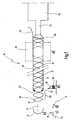
- Fig. Lais provided schematically provided with the general reference numeral 10 device for resecting organic tissue by means of high-frequency current.
- the device 10can be used, for example, in hysteroscopy for the removal of fibroids, polyps and endometrial tissue and, for example, in urology for the removal of prostatic adenomas.
- the device 10has a loop 12 which can be acted upon by high-frequency current.
- a loop 14 designed as a double helixadjoins the loop 12, which is arranged partially in a tube 16.
- a distal end 18 of the coil 14is connected to the distal loop 12.
- a distal portion 20 of the coil 14protrudes from a distal opening 22 of the tube 16.
- the rest A portion of the coil 14 which extends into the tube 16is at least partially fixedly connected to the tube 16, for example by gluing.
- a configurationmay be considered in which the coil 14 is not connected to the tube 16, so that only the coil 14 is set in rotation while the pipe 16 is formed fixed.
- At least the protruding from the tube 16 distal portion 20 of the coil 14is also acted upon by high frequency voltage, with the same high frequency voltage with which the distal loop 12 can be acted upon.
- the loop 12 and the distal portion 20 of the coil 14are designed to conduct current accordingly.
- the portion of the coil 14 extending through the tube 16may either be non-conducting or have appropriate insulation, such that the portion of the coil 14 extending into the tube 16 is electrically isolated from the distal portion 20.
- Fig. LaIn Fig. La) is indicated by the reference numeral 32, the electrical insulation of extending into the tube 16 portion of the coil 14 relative to the distal portion 20 of the coil 14.
- the loop 12is according to Fig. 1b ) in the form of a semicircle, wherein the plane of the loop 12 is inclined relative to a longitudinal axis 24, ie with the longitudinal axis 24 a Angle forms, or in other words not in the drawing plane in Fig. La) is located.
- the tube 16is also electrically insulated.
- the tube 16can also be formed from a preferably hard plastic, into the inner wall of which the section of the helix 14 extending into the tube 16 can also be incorporated.
- the distal portion 20 and thus the loop 12are contacted via an electrical lead 26 passing through the tube 16, for example a wire provided with insulation, the electrical lead 26 being respectively connected to or connected to a high frequency current generator (not shown).
- the electrical supply line 26which then, for example.
- the electrical supply line 26which then, for example.
- bladesi. elongated electrically conductive rods is formed, held on the device and electrically contacted.
- the helix 14extends essentially over the entire length of the tube 16, ie, extends to its proximal end 28.
- the helix 14may, however, also end in front of the proximal end of the tube 16, ie extend over only a partial length of the tube 16, for example, up to a position 17 or 19 in Fig. 1a ).
- This partial lengthcan be, for example, 4 cm.
- the portion 20 of the coil 14, which protrudes from the tube 16may, for example, have a length of 4 to 6 mm.
- a motor 30is provided, which in the embodiment according to Fig. 1a ) is arranged coaxially to the longitudinal axis 24 and to the tube 16 and the tube 16 itself set in rotation. About the rotation of the tube 16 so firmly connected coil 14 and the thus firmly connected loop 12 is set in rotation.
- the motor 30is an electric motor and may be formed as a hollow shaft motor.
- the loop 12 and the distal portion 20 of the coil 14are not electrically insulated.
- the loop 12allows frontal, i. Distal organic structures are cut under the action of high frequency current, while with the distal portion 20 of the coil 14 laterally located tissue structures can be cut under the action of high frequency current.
- the coil 14can be coagulated to achieve hemostasis.
- the inclination of the distal loop 12causes, during the rotation of the loop 12, that the tissue to be separated from the loop 12 is already oriented in the cutting process so that it penetrates into the interior of the coil 14, ie into the cylindrical interior of the coil 14 or of the tube 16 can occur.
- the loop 12can in accordance with in cross section Fig. 1c ) may be formed as a cutting blade, wherein a cutting edge 34 is oriented pointing in the interior of the coil 14.
- the loop 12may be formed of a rigid wire, such as steel wire, as in FIG Fig. 1d ), which correspondingly shows a round cross section of the loop 12.
- the diameter of the wirecan be 1/4 mm for cutting, 1 mm for coagulation, depending on the application. The choice of the diameter will depend on whether predominantly cut or coagulated.
- the helix 14is constructed in the embodiment shown of two longitudinally offset by half pitch helical turns and a total of cylindrical shape.
- the helix 14is used, in particular, in its section extending into the tube 16, tissue separated by means of the loop 12 and the distal section 20, which has initially entered the interior of the helix 14, in the direction of the proximal end of the tube 16, so that the separated tissue can be removed without additional manual intervention from the treatment area.
- the distal portion 20 of the coil 14, which protrudes from the tube 16may be formed of a rigid wire, in particular steel wire, or formed as a cutting blade with directed into the interior of the helix 14 cutting edge 36, as in Fig. 1e ) is shown.
- the design as a cutting blade with an inwardly directed cutting edge 36favors the morcellation of the separated tissue and the entry of the separated tissue into the interior of the helix 14.
- the portion of the coil 14 extending into the tube 16may also have a cutting edge directed into the interior of the coil 14, around the resected or separated pieces of tissue, which enter the tube 16, better dissipate towards the proximal end 28 of the tube.
- the portion of the coil 14 extending through the tube 16is preferably electrically isolated, as in FIG Fig. 1e ) is indicated at 38.
- the portion of the coil 14 extending into the tube 16may be of variable width or thickness of the coil 14.
- the edge of the distal opening 22 of the tube 16may itself be sharp and therewith cutting or blunt.
- the diameter of the tube 16is for example in a range of about 3 to about 6.5 mm, wherein the choice of the diameter of the tube 16 and thus also the coil 14 may be dependent on the size of the organic structures to be resected.
- the length of the tube 16is, for example, 10 to 30 cm.
- the rotational speed of the motor 30 and thus the coil 14 and the loop 12is adjustable in a range of 0 to about 1000 revolutions per minute, this adjustability is preferably stepless.
- the rotational speedis adjusted according to the nature of the tissue to be separated. An actuator for adjusting the rotational speed will be described later with reference to the other figures.
- the rotational speed of the motor 30may also be adjustable to fixed rotational speeds, for example a rotational speed of about 20 revolutions per minute and a rotational speed of about 300 revolutions per minute and another at about 800 revolutions per minute.
- the high-frequency current provided by the above-mentioned high-frequency current generatorwhich enables the cutting of tissue and coagulation, is transmitted to the coil 14 and the loop 12 via the electrical lead 26, which is electrically isolated, the high-frequency current corresponding to the cutting and / or Coagulation is designed.
- a foot pedalis provided for switching on or for regulating the parameters of the high-frequency current.
- the device 10is suitable for monopolar high-frequency current, but can also be designed with appropriate modification for bipolar applications.
- the proximal end 28 of the tube 16is further connected to a collecting container 40, for example a bottle, whereby the connection is accomplished, for example, by means of a flexible tube 42. Separate tissue transported proximally through the tube 16 is collected in the collection container 40.
- a collecting container 40for example a bottle
- the removal of separated tissue through the tube 16can be further improved by applying to the interior of the coil 14 or to the interior of the tube 16 a negative pressure reaching up to the collecting container 40, for example by means of a pump, the negative pressure or pressure being applied .
- the suction poweris variably adjustable, for example in a range of 0 to -1 bar.
- a device ENDOMAT®can be used as a pump
- Fig. 2 to 4Denote the same reference numerals as in Fig. 1 identical or identical in terms of their function parts of the device 10th
- Fig. 2 to 4the arrangement of tube 16, coil 14 and loop 12 is received in an outer shaft 44, such that the tube 16 and thus the coil 14 and the loop 12 in the outer shaft 44 are set in rotation.
- Fig. 3shows, the arrangement of tube 16, coil 14, loop 12 is made such that the distal portion 20, so the cutting active portion of the coil 14 and the loop 14 protrude from the outer shaft 44 distally.
- Fig. 3is the isolated, extending into the tube 16 section of the coil 14 shown with thicker lines.
- the tube 16, the helix 14 and the loop 12can be configured interchangeably in particular as a structural unit, in particular as a disposable part.
- different spiral widthscan be kept for the coil 14, which are each usable with the outer shaft 44.
- an embodiment of the tube 16 as a plastic partis particularly suitable.
- the coil 14is individually interchangeable with the loop 12.
- a handle 46is present, which is aligned obliquely to the longitudinal axis 24 in the region of the proximal end of the device 10.
- the outer shaft 44may for example have a diameter of 7 to 10 mm, without being limited thereto.
- Fig. 2extends the tube 16 into the handle 46, wherein the motor 30 is also received in the handle 46.
- the tube 16is correspondingly provided with a hinge 48 which transmits the rotation of the portion of the tube 16 in the handle 46 on the portion of the tube 16 which extends parallel to the longitudinal axis 24.
- the joint 48may be realized as a bevel gear, universal joint or as a flexible embodiment of the tube 16 in this area, to give examples.
- the motor 30may instead of as shown in Fig la) and instead of as in Fig. 2 be arranged outside the device 10. Such an external motor can then be connected via a shaft to the device 10 to drive the tube 16.
- a hand knobin particular a depressible switch 50 is arranged, which can be operated, for example, with the index finger of the hand holding the handle 46 to the rotational speed of the tube 16 and thus the coil 14 and the loop 12 continuously to adjust or to control.
- a cock, valve or the like 52is arranged on the handle, with which the vacuum applied to the interior of the tube 16 or the applied suction power to support the transport of separated tissue into the collecting container 40 (see FIG. Fig . 1 ) can be adjusted.
- the cock, valve or the like 52may also be positioned closer to the switch 50 so that an operation with the middle finger of the same hand holding the handle 46 is made possible in an ergonomic manner.
- the suction power through the pipe 16should be sensitively controllable, so that the dependent size of the working space can be controlled. Too high a suction power can lead to an undesirable collapse of the working space.
- connection 54is further arranged for the RF cable, with which the device 10 can be connected to the high frequency power generator. Since the electrical supply line to the coil 14 has to rotate with the coil 14, the supply line is provided with a sliding contact, for example a slip ring, in order to ensure current transfer from the fixed connection 54 to the coil 14.
- the outer shaft 44is further adapted to receive an endoscope 56 which is in Fig. 2 schematically illustrated at the proximal end with an eyepiece 58.
- an endoscope 56which is in Fig. 2 schematically illustrated at the proximal end with an eyepiece 58.
- a video camera connected to the endoscope 56may also be provided.
- a light guide terminal 59 for connecting a light cable for illumination lightis provided.
- a distal end 61 of the endoscope 56(see FIG. Fig. 3 ) is positioned approximately at the level of the distal portion 20 of the coil 14 and the loop 12 and preferably has an oblique projection optics, such as a 30 ° optics.
- the diameter of the endoscope or the endoscope opticsmay be, for example, 3 mm.
- the outer shaft 44further serves for supplying a rinsing liquid into the treatment area and for discharging liquid from the treatment area.
- a flushing connection 60 with tap or valve or the like 63 and a suction connection 62 with tap or valve or the like 65is provided on the outer shaft 44, these two connections being connected to a suitable suction and flushing source (not shown).
- the controls 63 and 65may also be positioned on the handle 46 so that they may be operated, for example, with the thumb of the hand holding the handle 46.
- the device 10is then suitable including the controls 50 and 52 for one-handed operation.
- the permanent irrigation of the surgical site and the region of distal portion 20 of coil 14 and loop 12is facilitated by a continuous flow of a nonconducting fluid, such as 1.5% GLYCOCOLLE, injected under low pressure into the surgical site.
- a nonconducting fluidsuch as 1.5% GLYCOCOLLE
- the supply of the rinsing liquid through the outer shaft 44can be effected for example by an inner tube 64, through which the endoscope 56 is passed, the remaining annular space between the endoscope 56 and the inner wall of the inner tube 64 then serves the supply of the rinsing liquid (see also Fig. 4c ), d) and e)).
- thin tubes 66may also lead from the irrigation port 60 to the distal end of the outer shaft 44.
- openings or openings 72for example, over a length of 2 cm of the outer shaft 44, preferably in full, provided, can be sucked through the liquid into the outer shaft 44 into it.
- the outer shaft 44may also be formed approximately oval in cross-section.
- the device 10allows separation of frontal or lateral tissue structures as well as coagulation and removal of severed tissue from the surgical site. There are no multiple interruptions or instrument changes required to allow hemostasis or removal of the separated tissue pieces. During resection, a slight pull may be applied to the non-resectable portion of the tissue to better expose or even sever the base of this tissue structure to prevent unwanted trimming of uninvolved structures.
- the resection of a myoma at a speed of the loop 12 and the coil 14 of 0 to 10 revolutions per minutecan be easily initiated until the tissue is inserted into the tube 16, with a closed cock or
- flushing liquid 63is introduced into the operating area via the flushing connection 63 and discharged via the suction connection 62, the balance between supply of the flushing liquid and suction of liquid being such that there is a slight overpressure for distension in the operation area.
- the cock or the valve 52is opened to suck the separated tissue from the tube 16 and then closed again.
- the faster speed of 50 to 300 revolutions per minute with partially opened cock or valve 52makes it possible to quickly aspirate all brittle and soft tissues (eg of the endometrium).
- the fast speedis mainly used for endometrial resections and the resection of certain polyps.
- the tissue extractionis preferably carried out with the ENDOMAT® device.
- the switch 50 for controlling the rotational speed of the coil 14 and the loop 12is designed to control the speed with high precision and progressively.
- the tissue structure to be resected or ablated(myoma, polyp or prostate adenoma) is exposed.
- the valve or valve 52closed, the resection or ablation is initiated with slight rotation (between 0 and 10 revolutions per minute) and activated high-frequency current until the obstruction of the distal end of the tube 16.
- the cock or valve 52is opened and the combination of the positive pressure of the purge with the negative vacuum suction pressure via the tap 52 and a rotation of the loop 12 and the coil 14 at medium speed with activated cutting or mixed flow allows for a continuous resection, for example of a fibroid, whereby the three functions of resection, removal of separated tissue and coagulation are ensured.
- a further advantage of the helix 14 extending into the tube 16is that, as soon as tissue has been drawn into the tube 16, due to the tube 16 extending into the tube 16 A portion of the coil 14 can be pulled on the tissue, for example a fibroid, whereby it can be attracted to the cavity, whereby the inaccessible in a conventional resection intermediate part of the tissue can be tightened and thus resected. This can also begin to release the fibroid or prostate adenoma from the wall to provide a better overview of the interface and to resect much safer.
Landscapes
- Health & Medical Sciences (AREA)
- Life Sciences & Earth Sciences (AREA)
- Surgery (AREA)
- Engineering & Computer Science (AREA)
- Medical Informatics (AREA)
- Veterinary Medicine (AREA)
- Biomedical Technology (AREA)
- Heart & Thoracic Surgery (AREA)
- Nuclear Medicine, Radiotherapy & Molecular Imaging (AREA)
- Molecular Biology (AREA)
- Animal Behavior & Ethology (AREA)
- General Health & Medical Sciences (AREA)
- Public Health (AREA)
- Orthopedic Medicine & Surgery (AREA)
- Physics & Mathematics (AREA)
- Plasma & Fusion (AREA)
- Otolaryngology (AREA)
- Surgical Instruments (AREA)
Abstract
Description
Translated fromGermanDie Erfindung betrifft eine Vorrichtung zur Resektion und/oder Ablation von organischem Gewebe mittels Hochfrequenzstrom, mit zumindest einer Wendel, wobei die Wendel um die Längsachse der Wendel in Rotation versetzbar ist.The invention relates to a device for resection and / or ablation of organic tissue by means of high-frequency current, with at least one helix, wherein the helix is set in rotation about the longitudinal axis of the helix.
Eine derartige Vorrichtung ist aus
Die aus
Eine Resektion oder Ablation organischer Strukturen wird beispielsweise in der Hysteroskopie zur Entfernung von Fibromen, Polypen und Gewebe des Endometriums und in der Urologie zur Entfernung von prostatischen Adenomen vorgenommen. Derartige Resektionen oder Ablationen organischer Strukturen werden herkömmlicherweise mittels eines Resektionsinstruments durchgeführt, das am distalen Ende eine elektrisch leitende und mit Hochfrequenzstrom beaufschlagbare Metallschlinge aufweist. Zur Durchführung eines Schneidvorganges wird die Schlinge mit monopolarer oder bipolarer Hochfrequenzspannung beaufschlagt und vom operierenden Arzt zum Herbeiführen eines Schnittes zum Abtrennen von Gewebe manuell in Richtung der Längsachse des Resektionsinstruments bewegt, und zwar in einer hin- und hergehenden Bewegung oder nur in einer Richtung. Die mit Hochfrequenzstrom beaufschlagte Schlinge verhält sich dabei wie ein elektrisches Skalpell. Die Schlinge ermöglicht auf diese Weise die Abtrennung von Gewebestücken gleichen Durchmessers. Eine Stillung von Blutungen, die mit dem Abtrennen von Gewebe einhergehen, kann ebenfalls mit derselben Schlinge durchgeführt werden, nachdem das Gewebestück von der Schlinge abgelöst wurde. Die so abgelösten Gewebestücke müssen zu einer anderen Zeit dann auf mechanische Weise aus dem Behandlungsareal entnommen werden.Resection or ablation of organic structures is carried out, for example, in hysteroscopy for the removal of fibroids, polyps and tissue of the endometrium and in urology for the removal of prostatic adenomas. Such resections or ablations of organic structures are conventionally carried out by means of a resection instrument which has an electrically conductive and high-frequency current-loadable metal loop at the distal end. To perform a cutting operation, the loop is subjected to monopolar or bipolar RF voltage and manually moved by the operating physician to effect a cut to sever tissue in the direction of the longitudinal axis of the resection instrument, in a reciprocating manner Motion or in one direction only. The loop subjected to high-frequency current behaves like an electric scalpel. The loop allows in this way the separation of tissue pieces of the same diameter. Stopping bleeding associated with tissue removal may also be accomplished with the same loop after the tissue piece has been detached from the loop. The detached tissue pieces must then be removed from the treatment area in a mechanical manner at another time.
Ein Nachteil derartiger herkömmlicher Vorrichtungen zur Resektion von Gewebe mittels Hochfrequenzstrom besteht darin, dass auf Grund der Tatsache, dass die abgetrennten Gewebestücke nach dem Abtrennen mittels eines weiteren Instruments, beispielsweise einer Fasszange, aus dem Behandlungsareal entnommen werden müssen, die Dauer des Eingriffs am Patienten erhöht ist. Die erhöhte Dauer des Eingriffs ist durch den erforderlichen mehrfachen Instrumentenwechsel zwischen dem Resektionsinstrument für den Vorgang des Abtrennens von Gewebe und dem Entnahmeinstrument für den Vorgang des Entnehmens des abgetrennten Gewebes bedingt. Ein weiterer Nachteil der herkömmlichen Vorrichtungen ist die Beschränkung ihres Einsatzes auf die bestimmte Indikation, für die sie vorgesehen sind. Des Weiteren ist die Sichtkontrolle bei diesen Vorrichtungen schwierig.A disadvantage of such conventional devices for resecting tissue by means of high-frequency current is that due to the fact that the separated tissue pieces must be removed after separation by means of another instrument, such as a forceps, from the treatment area, the duration of the procedure on the patient increases is. The increased duration of the procedure is due to the required multiple instrument changes between the resecting instrument for the process of separating tissue and the removal instrument for the process of removing the separated tissue. Another disadvantage of the conventional devices is the limitation of their use to the particular indication for which they are intended. Furthermore, visual inspection is difficult with these devices.
Der Erfindung liegt die Aufgabe zugrunde, eine Vorrichtung der eingangs genannten Art dahingehend weiterzubilden, dass die vorstehend beschriebenen Nachteile vermieden werden, dass insbesondere die Dauer eines Resektionseingriffs verringert werden kann.The invention has the object of developing a device of the type mentioned in such a way that the disadvantages described above are avoided, that in particular the duration of a resection intervention can be reduced.
Erfindungsgemäß wird diese Aufgabe hinsichtlich der eingangs genannten Vorrichtung dadurch gelöst, dass distal von der zumindest einen Wendel eine Schlinge angeordnet ist, wobei die Wendel und die Schlinge mit Hochfrequenzspannung beaufschlagbar sind, und dass die Anordnung aus Schlinge und Wendel um die Längsachse der Wendel in Rotation versetzbar ist.According to the invention this object is achieved with respect to the device mentioned above in that distally from the at least one coil a loop is arranged, the coil and the loop can be acted upon by high frequency voltage, and that the arrangement of loop and coil about the longitudinal axis of the coil in rotation is displaceable.
Mit der rotierenden distalen Schlinge können vorteilhafterweise Gewebestrukturen abgetrennt werden, die sich frontal vor der Schlinge befinden. Mit der sich an die Schlinge unmittelbar oder mittelbar anschließenden zumindest einen Wendel können dagegen Gewebestrukturen abgetrennt werden, die sich seitlich von der zumindest einen Wendel befinden. Durch die Beaufschlagung der Schlinge und der zumindest einen Wendel mit Hochfrequenzstrom wird das Abtrennen von Gewebe unter der Wirkung des Hochfrequenzstroms noch weiter verbessert. Ebenso können mittels Hochfrequenzstrom jedoch auch Blutungen durch Koagulation gestillt werden, die beim Abtrennen des Gewebes auftreten. Eine weitere Wirkung der rotierenden Wendel besteht nun vorteilhafterweise darin, dass abgetrenntes Gewebe in das Innere der Wendel mitgenommen werden kann, und wobei dieses in das Innere der Wendel eintretende abgetrennte Gewebe durch die Rotation der zumindest einen Wendel in Richtung proximales Ende der Vorrichtung transportiert werden kann. Mit der erfindungsgemäßen Vorrichtung ist es somit ohne Instrumentenwechsel möglich, eine Resektion von organischem Gewebe ununterbrochen durchzuführen und dabei gleichzeitig das abgetrennte Gewebe zu entnehmen und Blutungen zu stillen. Die erfindungsgemäße Vorrichtung ermöglicht es folglich, die Dauer eines Eingriffs gegenüber den herkömmlichen Vorrichtungen zu verringern. Die Vorrichtung eignet sich für monopolare, aber auch für bipolare Ausgestaltungen. In einer bevorzugten Ausgestaltung ist die Wendel als Doppelwendel oder Mehrfachwendel ausgebildet.With the rotating distal loop tissue structures can advantageously be separated, which are located frontally in front of the loop. On the other hand, fabric structures which are located laterally from the at least one helix can be separated with the at least one helix directly or indirectly adjoining the loop. By subjecting the loop and the at least one coil with high-frequency current, the separation of tissue under the effect of the high-frequency current is further improved. Likewise, by means of high-frequency current, however, bleeding by coagulation, which occurs during the separation of the tissue, can also be stopped. Another effect of the rotating coil is now advantageously that separated tissue can be taken into the interior of the coil, and wherein this separated tissue entering the interior of the coil can be transported by the rotation of the at least one coil in the direction of the proximal end of the device , With the device according to the invention, it is thus possible without instrument change to carry out a resection of organic tissue without interruption while at the same time removing the separated tissue and quenching bleeding. The device according to the invention thus makes it possible to reduce the duration of an intervention in comparison to the conventional devices. The device is suitable for monopolar, but also for bipolar embodiments. In a preferred embodiment, the helix is designed as a double helix or multiple helix.
"Doppelwendel" oder "Mehrfachwendel" bedeutet hier, dass die Wendel aus zwei oder mehreren schraubenlinienförmigen und vorzugsweise zylindrischen Strukturen aufgebaut ist. Die Ausgestaltung der zumindest einen Wendel als Doppelwendel oder Mehrfachwendel führt zum einen zu einer höheren Verwindungssteifigkeit der Wendel beim Resezieren festeren Gewebes, insbesondere wenn die Wendel in Längsrichtung lang ausgebildet ist, und außerdem kann auf diese Weise die Wirkung der Mitnahme abgetrennten Gewebes nach proximal noch verbessert werden."Double helix" or "multiple helix" here means that the helix is composed of two or more helical and preferably cylindrical structures. The design of the at least one helix as a double helix or multiple helix leads on the one hand to a higher torsional stiffness of the helix when resecting firmer tissue, in particular if the helix is long in the longitudinal direction, and, moreover, in this way the effect of entrainment of severed tissue to the proximal end can be improved become.
Wie erwähnt, ist die zumindest eine Wendel vorzugsweise so ausgebildet, dass sie eine Abtragung seitlich von der Wendel befindlichen Gewebes ermöglicht.As mentioned, the at least one helix is preferably designed such that it allows removal of tissue located laterally from the helix.
Weiterhin ist die Wendel vorzugsweise so ausgebildet, dass sie einen Transport abgetrennten Gewebes nach proximal ermöglicht.Furthermore, the helix is preferably designed so that it allows a transport of separated tissue to the proximal.
In einer weiteren bevorzugten Ausgestaltung ist die Wendel teilweise von einem Rohr umgeben und mit diesem zumindest teilweise fest verbunden, wobei ein distaler Abschnitt der Wendel aus einer distalen Öffnung des Rohrs aus dem Rohr herausragt.In a further preferred embodiment, the helix is partially surrounded by a tube and at least partially firmly connected thereto, wherein a distal portion of the helix protrudes from a distal opening of the tube from the tube.
Hierbei ist von Vorteil, dass das Rohr eine noch weiter erhöhte Verwindungssteifigkeit der Wendel gewährleistet. Der aus der distalen Öffnung des Rohrs herausragende distale Abschnitt der Wendel ist dann der aktiv schneidende und zumindest der Abschnitt, der mit Hochfrequenzstrom beaufschlagt wird. Die feste Verbindung zwischen Wendel und Rohr kann beispielsweise durch Kleben hergestellt sein.It is advantageous that the tube ensures an even greater torsional rigidity of the helix. The distal portion of the helix projecting from the distal opening of the tube is then the actively cutting and at least the portion that is exposed to high frequency current. The solid Connection between helix and tube can be made for example by gluing.
Dabei ist es bevorzugt, wenn das Rohr mittels eines Motors in Rotation versetzbar ist.It is preferred if the tube is set in rotation by means of a motor.
Hierdurch wird ein konstruktiv einfacher Antrieb geschaffen, da der Motor lediglich das Rohr in Rotation versetzen muss, und über die feste Verbindung der Wendel mit dem Rohr wird dann die Wendel ebenfalls in Rotation versetzt.As a result, a structurally simple drive is created, since the engine only has to put the tube in rotation, and the helix is then set in rotation via the fixed connection of the helix with the tube.
Alternativ zu der Ausgestaltung, wonach die Wendel zumindest teilweise fest mit dem Rohr verbunden ist, ist es alternativ bevorzugt, wenn die Wendel nicht mit dem Rohr fest verbunden ist, sondern relativ zum Rohr frei drehbar ist.As an alternative to the configuration according to which the helix is at least partially fixedly connected to the tube, it is alternatively preferred if the helix is not firmly connected to the tube, but is freely rotatable relative to the tube.
In diesem Fall ist das Rohr vorzugsweise feststehend, und die Wendel wird mittels des Motors in Rotation versetzt. Ein Vorteil der Ausgestaltung, nach der sich nur die Wendel und die Schlinge dreht, besteht darin, dass die Schlinge und die Wendel, die einem Verschleiß unterworfen sind, einzeln ausgetauscht werden können, während das Rohr, das keinem Verschleiß oder keinem wesentlichen Verschleiß unterliegt, weiter verwendet werden kann.In this case, the tube is preferably fixed, and the helix is rotated by means of the motor. An advantage of the embodiment, according to which only the helix and the loop rotate, is that the loop and the helix, which are subject to wear, can be replaced individually, while the tube, which is not subject to wear or substantial wear, can be used further.
Weiterhin ist es bevorzugt, wenn sich die Wendel zumindest annähernd über die gesamte Länge des Rohrs erstreckt.Furthermore, it is preferred if the helix extends at least approximately over the entire length of the tube.
Durch diese Maßnahme ist die Mitnahme- bzw. Transportwirkung der Wendel auf das abgetrennte Gewebe bis zum proximalen Ende des Rohrs zur einfachen Entnahme bzw. zum Auffangen des abgetrennten Gewebes in einen Behälter vorhanden.By this measure, the entrainment or transport effect of the coil on the separated tissue to the proximal end of the tube for easy removal or for collecting the separated tissue in a container available.
Alternativ zu der zuvor genannten Ausgestaltung kann es auch bevorzugt sein, wenn sich die Wendel nur über eine Teillänge des Rohrs erstreckt.Alternatively to the aforementioned embodiment, it may also be preferred if the helix extends only over a partial length of the tube.
Diese Maßnahme ist insbesondere mit der oben genannten Maßnahme, wonach nur die Wendel in Rotation versetzbar ist, vorteilhaft, da der Austausch der Wendel einfacher zu bewerkstelligen ist.This measure is particularly advantageous with the above-mentioned measure, according to which only the helix can be set into rotation, since the replacement of the helix is easier to accomplish.
Als Stromzuführung für die Wendel können dann vorzugsweise Blades verwendet werden, bei einer Doppelwendel entsprechend zwei Blades, die vom proximalseitigen HF-Anschluss bis etwa zum proximalen Ende der Wendel sich durch das Rohr 16 erstrecken und dort mit der Wendel kontaktiert sind. Die Blades können über Schleifkontakte, insbesondere Schleifringe, mit dem HF-Anschluss verbunden sein, da die Blades mit der Wendel mitrotieren müssen. Die Blades können bei einer austauschbaren Ausgestaltung der Wendel im Rohr verbleiben.Blades can then preferably be used as the current supply for the coil, in the case of a double helix correspondingly two blades which extend from the proximal-side HF connection to approximately the proximal end of the helix through the
Die leichtere Austauschbarkeit der Schlinge und der Wendel ohne Austauschbarkeit des Rohrs hat des Weiteren den Vorteil, dass für verschiedene Anwendungen rasch eine Ersatzschlinge mit Ersatzwendel in die Vorrichtung eingebaut werden können, ohne dass dazu eine größere Zerlegung der Vorrichtung erforderlich ist.The easier interchangeability of the loop and the coil without interchangeability of the tube has the further advantage that for different applications quickly a replacement loop with spare coil can be installed in the device, without requiring a major disassembly of the device is required.
In einer weiteren bevorzugten Ausgestaltung ist der sich im Rohr erstreckende Abschnitt der Wendel elektrisch isoliert. Hierbei ist von Vorteil, dass das im Innern der Wendel durch das Rohr transportierte abgetrennte Gewebe nicht an der Wendel auf Grund von Erwärmung anhaftet.In a further preferred embodiment, the section of the coil extending in the tube is electrically insulated. It is advantageous that the separated tissue transported inside the helix through the tube does not adhere to the helix due to heating.
Ebenso ist bevorzugt, wenn das Rohr elektrisch isoliert ist.It is also preferred if the tube is electrically insulated.
Hierdurch wird eine Gefahr für den bedienenden Arzt vermieden.This avoids any danger to the operator.
Dagegen ist der aus dem Rohr herausragende Abschnitt der Wendel vorzugsweise nicht elektrisch isoliert.In contrast, the protruding from the pipe section of the coil is preferably not electrically insulated.
In einer weiteren bevorzugten Ausgestaltung ist der aus dem Rohr herausragende Abschnitt der Wendel aus einem steifen Draht gebildet oder als Schneidklinge mit nach innen gerichteter Schneide ausgebildet.In a further preferred embodiment, the protruding from the pipe section of the helix is formed of a rigid wire or formed as a cutting blade with inwardly directed cutting edge.
Insbesondere die Ausgestaltung der Wendel als Schneidklinge mit nach innen gerichteter Schneide in ihrem aus dem Rohr herausragenden Abschnitt ist geeignet, das abgetrennte Gewebe weiter zu morcellieren und den Transport des abgetrennten Gewebes in das Innere der zumindest einen Wendel zu begünstigen.In particular, the configuration of the helix as a cutting blade with an inwardly directed cutting edge in its section protruding from the tube is suitable for further morcellizing the severed tissue and favoring the transport of the separated tissue into the interior of the at least one helix.
In einer weiteren bevorzugten Ausgestaltung weist der sich im Rohr erstreckende Abschnitt der Wendel, der vorzugsweise eine variable Breite aufweist, eine nach innen gerichtete Schneide auf.In a further preferred embodiment, the section of the helix extending in the tube, which preferably has a variable width, has an inwardly directed cutting edge.
Die nach innen gerichtete Schneide hat den Vorteil, dass der Transport von in das Rohr eintretenden bzw. eingetretenen abgetrennten Gewebestücken nach proximal weiter begünstigt wird.The inwardly directed cutting edge has the advantage that the transport of separated tissue pieces entering or entering the tube is further favored proximally.
In weiteren bevorzugten Ausgestaltungen kann die distale Öffnung des Rohrs einen stumpfen oder schneidenden Rand aufweisen.In further preferred embodiments, the distal opening of the tube may have a blunt or cutting edge.
Das Rohr weist vorzugsweise einen Durchmesser im Bereich von etwa 3 bis etwa 6,5 mm auf, wobei jedoch auch außerhalb dieses Bereiches liegende Durchmesser je nach Anwendung in Betracht gezogen werden können.The tube preferably has a diameter in the range of about 3 to about 6.5 mm, but also outside this range diameters may be considered depending on the application.
Die Schlinge am distalen Ende der Vorrichtung ist vorzugsweise halbkreisförmig ausgebildet, und weist vorzugsweise einen Durchmesser von 4 bis 7 mm auf.The loop at the distal end of the device is preferably semicircular, and preferably has a diameter of 4 to 7 mm.
Die Schlinge ist weiterhin vorzugsweise aus einem steifen elektrisch leitenden Draht gebildet oder als Schneidklinge ausgebildet, wobei im letzteren Fall die Schneide nach innen gerichtet ist.The loop is further preferably formed of a rigid electrically conductive wire or formed as a cutting blade, in the latter case, the cutting edge is directed inwards.
Weiterhin ist es bevorzugt, wenn die Ebene der Schlinge gegenüber der Längsachse geneigt, vorzugsweise geringfügig geneigt ist, derart, dass von der Schlinge abgetrenntes Gewebe zum Inneren der Wendel hin orientiert wird.Furthermore, it is preferred if the plane of the loop is inclined relative to the longitudinal axis, preferably slightly inclined, such that tissue separated from the loop is oriented toward the interior of the coil.
Hierbei ist von Vorteil, dass das von der Schlinge frontal abgetrennte Gewebe leichter in das Innere der Wendel zwecks Transport nach proximal eintreten kann.In this case, it is advantageous that the tissue severed from the sling frontally can more easily enter the interior of the coil for the purpose of transporting proximally.
In einer weiteren bevorzugten Ausgestaltung ist die Drehgeschwindigkeit der zumindest einen Wendel und der Schlinge in einem Bereich von 0 bis 1000 Umdrehungen pro Minute, vorzugsweise stufenlos, einstellbar.In a further preferred embodiment, the rotational speed of the at least one coil and the loop in a range of 0 to 1000 revolutions per minute, preferably continuously, adjustable.
Hierbei ist von Vorteil, dass die Drehgeschwindigkeit und damit die Schneidwirkung an die Festigkeit des zu resezierenden Gewebes angepasst werden kann.It is advantageous that the rotational speed and thus the cutting action can be adapted to the strength of the tissue to be resected.
Es kann ebenso vorzugsweise vorgesehen sein, dass feste Drehgeschwindigkeiten voreingestellt sind, beispielsweise von 20 Umdrehungen pro Minute, 300 und 800 Umdrehungen pro Minute, die dann beispielsweise durch einen entsprechenden Betätigungsknopf rasch eingestellt werden können.It may also preferably be provided that fixed rotational speeds are preset, for example of 20 revolutions per minute, 300 and 800 revolutions per minute, which can then be set rapidly, for example by means of a corresponding actuating button.
Ebenso ist es alternativ oder zusätzlich bevorzugt, wenn eine Feinregulierung, in bspw. zwei Bereichen, bspw. in einem Bereich von 0 bis 20 Umdrehungen pro Minute und in einem Bereich von 300 bis 800 Umdrehungen pro Minute vorgesehen ist.Likewise, it is alternatively or additionally preferred if a fine adjustment, for example in two areas, for example in a range of 0 to 20 revolutions per minute and in a range of 300 to 800 revolutions per minute is provided.
Zur Einstellung bzw. Steuerung der Drehgeschwindigkeit ist vorzugsweise ein an einem proximal an der Vorrichtung vorhandenen Handgriff angeordneter Betätigungsknopf oder ein Fußpedal vorgesehen.For setting or controlling the rotational speed, an actuating button or a foot pedal arranged on a handle provided proximally on the device is preferably provided.
Der am Handgriff angeordnete Betätigungsknopf ist vorzugsweise so positioniert, dass er mit derselben Hand betätigbar ist, mit der die Vorrichtung in der Hand gehalten wird.The operating knob disposed on the handle is preferably positioned so that it is operable with the same hand with which the device is held in the hand.
In einer weiteren bevorzugten Ausgestaltung wird der Hochfrequenzstrom von einem Hochfrequenzstromgenerator bereitgestellt und ist zum Schneiden und Koagulieren ausgelegt, wobei der Hochfrequenzstrom, vorzugsweise durch ein Fußpedal, einschaltbar ist.In a further preferred embodiment, the high-frequency current is provided by a high-frequency current generator and is designed for cutting and coagulation, wherein the high-frequency current, preferably by a foot pedal, can be switched on.
Die erfindungsgemäße Vorrichtung ist vorzugsweise dazu ausgelegt, sowohl unter der Wirkung von Hochfrequenzstrom zu schneiden als auch unter der Wirkung von Hochfrequenzstrom zu koagulieren, wozu ggf. die Parameter des Hochfrequenzstroms wie Amplitude, Frequenz und ggf. eine Amplitudenmodulation, geeigneterweise ausgelegt und eingestellt sein müssen. Der bedienende Arzt kann selbst die Dauer und den Einsatzzeitpunkt des Hochfrequenzstroms durch Ein- und Ausschalten bestimmen.The device according to the invention is preferably designed both to cut under the action of high-frequency current and to coagulate under the action of high-frequency current, for which, if necessary, the parameters of the high-frequency current such as amplitude, frequency and possibly an amplitude modulation, must be suitably designed and adjusted. The operating physician can determine the duration and time of use of the high-frequency current by switching it on and off.
In einer weiteren bevorzugten Ausgestaltung ist ein proximales Ende des Innenraums der Wendel, beispielsweise über einen Schlauch, mit einem Auffangbehälter, beispielsweise einer Flasche, zur Aufnahme von Gewebestücken verbunden.In a further preferred embodiment, a proximal end of the interior of the coil, for example via a hose, connected to a collecting container, such as a bottle, for receiving tissue pieces.
Hierbei ist von Vorteil, dass die über die zumindest eine Wendel von distal nach proximal transportierten Gewebestücke sogleich in einen Behälter abgeführt werden, ohne dass hierzu eine weitere Manipulation erforderlich ist.In this case, it is advantageous that the tissue pieces transported via the at least one helix from distal to proximal are readily removed into a container without requiring further manipulation for this purpose.
In einer weiteren bevorzugten Ausgestaltung ist, beispielsweise mittels einer Pumpe, an den Innenraum der Wendel bzw. des Rohrs ein vorzugsweise einstellbarer Unterdruck anlegbar.In a further preferred embodiment, for example by means of a pump, a preferably adjustable negative pressure can be applied to the interior of the helix or the tube.
Hierbei ist von Vorteil, dass im Fall, dass der Mitnahmeeffekt der rotierenden Wendel zum Abtransport des abgetrennten Gewebes von distal nach proximal nicht oder nicht vollständig ausreicht, der angelegte Unterdruck die Entnahme der abgetrennten Gewebestücke zumindest unterstützt und eine vollständige Entnahme der abgetrennten Gewebestücke aus dem Körper gewährleistet.It is advantageous that, in the event that the entrainment effect of the rotating coil for removing the separated tissue from distal to proximal not sufficient or not completely sufficient, the applied negative pressure, the removal of the separated pieces of tissue at least support and complete removal of the separated pieces of tissue from the body guaranteed.
In einer weiteren bevorzugten Ausgestaltung ist ein Außenschaft vorgesehen, um die Anordnung aus dem Rohr und der Wendel und der Schlinge in dem Außenschaft aufzunehmen, wobei die Schlinge und der aus dem Rohr herausragende Abschnitt der Wendel aus dem Außenschaft herausragen.In a further preferred embodiment, an outer shaft is provided to receive the assembly of the tube and the coil and the loop in the outer shaft, wherein the loop and protruding from the tube portion of the coil protrude from the outer shaft.
Hierbei ist von Vorteil, dass sich die Anordnung aus dem Rohr, der Wendel und der Schlinge nach Aufnahme in den Außenschaft ggf. einfacher durch einen Trokar oder einen natürlichen Zugang in das Operationsgebiet einführen lässt und dass die Vorrichtung mit zusätzlichen Funktionen wie Sichtkontrolle, Spülen und dgl. versehen werden kann.In this case, it is advantageous that the arrangement of the tube, the coil and the loop after insertion into the outer shaft, if necessary, can be more easily introduced through a trocar or a natural access in the operating area and that the device with additional functions such as visual inspection, rinsing and Like. Can be provided.
Dabei ist es weiterhin bevorzugt, wenn der Außenschaft zusätzlich zur Aufnahme eines Endoskops ausgelegt ist.It is further preferred if the outer shaft is additionally designed for receiving an endoscope.
Mit dem Endoskop kann vorteilhafterweise der Vorgang der Resektion im Operationsgebiet unter Sicht kontrolliert werden. Das Endoskop hat vorzugsweise eine Schrägvorausblick-Optik, beispielsweise eine 30°-Optik. Anstelle eines klassischen Endoskops mit einem Bildübertragungssystem aus Linsen kann auch ein Endoskop mit Bildübertragung durch Lichtfasern oder ein Videoendoskop mit distalem Bildsensor verwendet werden.With the endoscope advantageously the process of resection in the surgical field can be controlled under view. The endoscope preferably has an oblique projection optic, for example a 30 ° optic. Instead of a classic endoscope with an image transmission system made of lenses, an endoscope with image transmission by optical fibers or a video endoscope with a distal image sensor can also be used.
Des Weiteren ist es bevorzugt, wenn der Außenschaft zumindest eine Leitung zum Zuführen von Spülflüssigkeit in das Operationsgebiet und/oder zumindest eine Leitung zum Absaugen von Flüssigkeit aus dem Operationsgebiet aufweist.Furthermore, it is preferred if the outer shaft has at least one line for supplying rinsing liquid into the operating area and / or at least one line for aspirating liquid out of the operating area.
Durch Spülen kann Blut ausgespült werden, wodurch eine gute Sichtkontrolle, beispielsweise durch das zuvor erwähnte Endoskop, aufrecht erhalten werden kann.Rinsing can flush out blood, allowing good visual control, for example through the aforementioned endoscope, to be maintained.
Das Zuleiten von Spülflüssigkeit erfolgt vorzugsweise unter geringem Druck. Die Absaugung der Spülflüssigkeit kann durch den verbleibenden Raum innerhalb des Außenschafts nach proximal erfolgen, wobei im distalen Bereich des Außenschafts eine Mehrzahl von Saugöffnungen vorhanden sein können, durch die Flüssigkeit in den Außenschaft hinein angesaugt werden kann.The supply of rinsing liquid is preferably carried out under low pressure. The suction of the rinsing liquid can take place proximally through the remaining space within the outer shaft, wherein a plurality of suction openings can be present in the distal area of the outer shaft, through which liquid can be sucked into the outer shaft.
Weitere Vorteile und Merkmale ergeben sich aus der nachfolgenden Beschreibung und der beigefügten Zeichnung.Further advantages and features will become apparent from the following description and the accompanying drawings.
Es versteht sich, dass die vorstehend genannten und nachstehend noch zu erläuternden Merkmale nicht nur in der jeweils angegebenen Kombination, sondern auch in anderen Kombinationen oder in Alleinstellung verwendbar sind, ohne den Rahmen der vorliegenden Erfindung zu verlassen.It is understood that the features mentioned above and those yet to be explained can be used not only in the particular combination given, but also in other combinations or in isolation, without departing from the scope of the present invention.
Ausführungsbeispiele der Erfindung sind in der Zeichnung dargestellt und werden mit Bezug auf diese hiernach näher beschrieben. Es zeigen:
- Fig. la) bis e)
- eine Vorrichtung zur Resektion und/oder Ablation von organischem Gewebe mittels Hochfrequenzstrom, wobei Fig. la) eine schematische Seitenansicht der Vorrichtung und
Fig. 1b ) bis e) Einzelheiten der Vorrichtung in Alleinstellung und teilweise in vergrößertem Maßstab zeigen; - Fig. 2
- schematisch eine gegenüber
Fig. 1 modifizierte Vorrichtung zur Resektion und/oder Ablation von organischem Gewebe mittels Hochfrequenzstrom in Seitenansicht; - Fig. 3
- einen distalen Abschnitt der Vorrichtung in
Fig. 2 im Längsschnitt und vergrößertem Maßstab; und - Fig. 4a) bis e)
- weitere Einzelheiten der Vorrichtung in
Fig. 2 und3 in verschiedenen Ausführungsvarianten, wobeiFig. 4a ) eine Teilseitenansicht undFig. 4b ) bis e) Vorderansichten der Vorrichtung zeigen.
- Fig. La) to e)
- a device for resection and / or ablation of organic tissue by means of high frequency current, wherein Fig. La) is a schematic side view of the device and
Fig. 1b ) to e) show details of the device alone and partly on an enlarged scale; - Fig. 2
- schematically one opposite
Fig. 1 modified device for resection and / or ablation of organic tissue by means of high frequency current in side view; - Fig. 3
- a distal portion of the device in FIG
Fig. 2 in longitudinal section and on an enlarged scale; and - Fig. 4a) to e)
- further details of the device in
Fig. 2 and3 in different embodiments, whereinFig. 4a ) a partial page view andFig. 4b ) to e) show front views of the device.
In Fig. la) ist schematisch eine mit dem allgemeinen Bezugszeichen 10 versehene Vorrichtung zum Resezieren von organischem Gewebe mittels Hochfrequenzstrom dargestellt.In Fig. La) is provided schematically provided with the
Die Vorrichtung 10 kann beispielsweise in der Hysteroskopie zur Entfernung von Fibromen, Polypen und Endometriumsgewebe und beispielsweise in der Urologie zur Entfernung prostatischer Adenome verwendet werden.The
Am äußeren distalen Ende weist die Vorrichtung 10 eine mit Hochfrequenzstrom beaufschlagbare Schlinge 12 auf. An die Schlinge 12 schließt sich im gezeigten Ausführungsbeispiel unmittelbar eine als Doppelwendel ausgebildete Wendel 14 an, die teilweise in einem Rohr 16 angeordnet ist.At the outer distal end, the
Ein distales Ende 18 der Wendel 14 ist mit der distalen Schlinge 12 verbunden. Ein distaler Abschnitt 20 der Wendel 14 ragt aus einer distalen Öffnung 22 des Rohrs 16 heraus. Der übrige Abschnitt der Wendel 14, der sich in das Rohr 16 hinein erstreckt, ist mit dem Rohr 16 zumindest teilweise fest verbunden, beispielsweise durch Kleben.A
Anstelle einer zumindest teilweise festen Verbindung der Wendel 14 mit dem Rohr 16 kann auch eine Ausgestaltung in Betracht gezogen werden, bei der die Wendel 14 nicht mit dem Rohr 16 verbunden ist, so dass nur die Wendel 14 in Rotation versetzbar ist, während das Rohr 16 feststehend ausgebildet ist.Instead of an at least partially fixed connection of the
Zumindest der aus dem Rohr 16 herausragende distale Abschnitt 20 der Wendel 14 ist ebenfalls mit Hochfrequenzspannung beaufschlagbar, und zwar mit derselben Hochfrequenzspannung, mit der auch die distale Schlinge 12 beaufschlagbar ist. Die Schlinge 12 und der distale Abschnitt 20 der Wendel 14 sind entsprechend stromleitend ausgebildet. Der sich durch das Rohr 16 erstreckende Abschnitt der Wendel 14 kann entweder nicht stromleitend ausgebildet sein oder eine entsprechende Isolierung aufweisen, so dass der sich in das Rohr 16 erstreckende Abschnitt der Wendel 14 gegen den distalen Abschnitt 20 elektrisch isoliert ist.At least the protruding from the
In Fig. la) ist mit dem Bezugszeichen 32 die elektrische Isolierung des sich in das Rohr 16 erstreckenden Abschnitts der Wendel 14 gegenüber dem distalen Abschnitt 20 der Wendel 14 angedeutet.In Fig. La) is indicated by the
Die Schlinge 12 ist gemäß
Das Rohr 16 ist ebenfalls elektrisch isoliert. Das Rohr 16 kann anstatt aus Metall auch aus einem vorzugsweise harten Kunststoff ausgebildet sein, in dessen Innenwand der sich in das Rohr 16 erstreckende Abschnitt der Wendel 14 auch eingearbeitet sein kann.The
Der distale Abschnitt 20 und damit die Schlinge 12 sind über eine durch das Rohr 16 hindurchgehende elektrische Zuleitung 26, beispielsweise einen mit Isolation versehenen Draht, kontaktiert, wobei die elektrische Zuleitung 26 entsprechend mit einem nicht dargestellten Hochfrequenzstromgenerator verbunden ist oder verbunden werden kann.The
Im Fall, dass nur die Wendel 14 in Rotation versetzbar ist, und nicht jedoch das Rohr 16, dient die elektrische Zuleitung 26, die dann bspw. in Form von Blades, d.h. langerstreckten elektrisch leitenden Stangen ausgebildet ist, an der Vorrichtung gehalten und elektrisch kontaktiert.In the event that only the
Die Wendel 14 erstreckt sich im Wesentlichen über die gesamte Länge des Rohrs 16, d.h. reicht bis zu dessen proximalen Ende 28. Die Wendel 14 kann aber auch vor dem proximalen Ende des Rohrs 16 enden, d.h. sich nur über eine Teillänge des Rohrs 16 erstrecken, bspw. bis zu einer Stelle 17 oder 19 in
Die Wendel 14 und die Schlinge 12 sind zusammen um die Längsachse 24 der Wendel 14 in Rotation versetzbar. Dazu ist ein Motor 30 vorgesehen, der in dem Ausführungsbeispiel gemäß
Der Motor 30 ist ein Elektromotor und kann als Hohlwellenmotor ausgebildet sein.The
Die Schlinge 12 und der distale Abschnitt 20 der Wendel 14 sind elektrisch nicht isoliert. Wenn das Rohr 16 und damit die Wendel 14 und die Schlinge 12 in Rotation versetzt werden, können mit der Schlinge 12 frontale, d.h. distalseitige organische Strukturen unter der Wirkung von Hochfrequenzstrom geschnitten werden, während mit dem distalen Abschnitt 20 der Wendel 14 seitlich befindliche Gewebestrukturen unter der Wirkung von Hochfrequenzstrom geschnitten werden können. Ebenso kann mit der Schlinge 12 und dem distalen Abschnitt 20 der Wendel 14 koaguliert werden, um eine Blutstillung zu erreichen.The
Die Schrägstellung der distalen Schlinge 12 bewirkt bei der Rotation der Schlinge 12, dass das von der Schlinge 12 abzutrennendes Gewebe beim Schneidvorgang bereits so orientiert wird, dass es in das Innere der Wendel 14, d.h. in den zylindrischen Innenraum der Wendel 14 bzw. des Rohrs 16 eintreten kann. Um diesen Effekt noch zu verstärken, kann die Schlinge 12 im Querschnitt gemäß
Die Schlinge 12 kann jedoch auch aus einem steifen Draht, beispielsweise Stahldraht, gebildet sein, wie in
Die Wendel 14 ist in dem gezeigten Ausführungsbeispiel aus zwei in Längsrichtung um die halbe Ganghöhe versetzten schraubenlinienförmigen Windungen aufgebaut und insgesamt von zylindrischer Form. Die Wendel 14 dient insbesondere in ihrem Abschnitt, der sich in das Rohr 16 erstreckt, mittels der Schlinge 12 und dem distalen Abschnitt 20 abgetrenntes Gewebe, das zunächst in das Innere der Wendel 14, eingetreten ist in Richtung proximales Ende des Rohrs 16 zu transportieren, so dass das abgetrennte Gewebe ohne zusätzliche manuelle Eingriffe aus dem Behandlungsareal entnommen werden kann.The
Der distale Abschnitt 20 der Wendel 14, der aus dem Rohr 16 herausragt, kann aus einem steifen Draht, insbesondere Stahldraht, gebildet sein, oder als Schneidklinge mit in das Innere der Wendel 14 gerichteter Schneide 36 ausgebildet sein, wie in
Der sich in das Rohr 16 erstreckende Abschnitt der Wendel 14 kann ebenfalls eine in das Innere der Wendel 14 gerichtete Schneide aufweisen, um die resezierten bzw. abgetrennten Gewebestücke, die in das Rohr 16 eintreten, besser in Richtung proximales Ende 28 des Rohrs abzuführen. Wie bereits zuvor erwähnt, ist jedoch der sich durch das Rohr 16 erstreckende Abschnitt der Wendel 14 vorzugsweise elektrisch isoliert, wie in
Der Rand der distalen Öffnung 22 des Rohrs 16 kann selbst scharf und damit schneidend oder stumpf sein.The edge of the
Der Durchmesser des Rohrs 16 liegt beispielsweise in einem Bereich von etwa 3 bis etwa 6,5 mm, wobei die Wahl des Durchmessers des Rohrs 16 und damit auch der Wendel 14 von der Größe der zu resezierenden organischen Strukturen abhängig sein kann. Die Länge des Rohrs 16 beträgt bspw. 10 bis 30 cm.The diameter of the
Die Drehgeschwindigkeit des Motors 30 und damit der Wendel 14 und der Schlinge 12 ist einstellbar in einem Bereich von 0 bis etwa 1000 Umdrehungen pro Minute, wobei diese Einstellbarkeit vorzugsweise stufenlos ist. Die Drehgeschwindigkeit wird entsprechend der Beschaffenheit des abzutrennenden Gewebes eingestellt. Ein Betätigungselement zum Einstellen der Drehgeschwindigkeit wird später noch mit Bezug auf die weiteren Figuren beschrieben.The rotational speed of the
Ferner kann die Drehgeschwindigkeit des Motors 30 auch auf feste Drehgeschwindigkeiten einstellbar sein, beispielsweise eine Drehgeschwindigkeit von etwa 20 Umdrehungen pro Minute und eine Drehgeschwindigkeit von etwa 300 Umdrehungen pro Minute und eine weitere bei etwa 800 Umdrehungen pro Minute.Further, the rotational speed of the
Der von dem oben erwähnten Hochfrequenzstromgenerator bereitgestellte Hochfrequenzstrom, der das Schneiden von Gewebe und die Koagulation ermöglicht, wird über die elektrische Zuleitung 26, die elektrisch isoliert ist, auf die Wendel 14 und die Schlinge 12 übertragen, wobei der Hochfrequenzstrom entsprechend zum Schneiden und/oder Koagulieren ausgelegt ist. In nicht dargestellter Weise ist zum Einschalten bzw. zur Regulierung der Parameter des Hochfrequenzstroms ein Fußpedal vorgesehen. Die Vorrichtung 10 eignet sich für monopolaren Hochfrequenzstrom, kann jedoch auch bei entsprechender Modifikation für bipolare Anwendungen ausgelegt werden.The high-frequency current provided by the above-mentioned high-frequency current generator, which enables the cutting of tissue and coagulation, is transmitted to the
Das proximale Ende 28 des Rohrs 16 ist ferner mit einem Auffangbehälter 40, beispielsweise einer Flasche, verbunden bzw. verbindbar, wobei die Verbindung beispielsweise über einen biegsamen Schlauch 42 bewerkstelligt wird. Durch das Rohr 16 nach proximal transportiertes abgetrenntes Gewebe wird in dem Auffangbehälter 40 gesammelt.The
Die Entnahme abgetrennten Gewebes durch das Rohr 16 hindurch kann weiter verbessert werden, indem an das Innere der Wendel 14 bzw. an das Innere des Rohrs 16 ein bis zu dem Auffangbehälter 40 reichender Unterdruck, beispielsweise mittels einer Pumpe, angelegt wird, wobei der Unterdruck bzw. die Saugleistung variabel einstellbar ist, beispielsweise in einem Bereich von 0 bis -1 bar. Als Pumpe kann bspw. ein Gerät ENDOMAT® verwendet werdenThe removal of separated tissue through the
Mit Bezug auf
In
Gemäß
Wie aus
Bei der Vorrichtung, gemäß
Bei der Ausgestaltung, wonach sich nur die Wendel 14 dreht, nicht aber das Rohr 16, ist die Wendel 14 mit der Schlinge 12 einzeln austauschbar.In the embodiment, according to which only the
Es können Wendeln 14 unterschiedlicher Durchmesser und unterschiedlicher Ganghöhen der Windungen und unterschiedlicher Querschnittsgeometrien der Wendel 14 bereitgehalten werden.It can coils 14 of different diameters and different pitches of the turns and different cross-sectional geometries of the
An dem Außenschaft 44 ist ein Handgriff 46 vorhanden, der im Bereich des proximalen Endes der Vorrichtung 10 schräg zur Längsachse 24 ausgerichtet ist.On the
Der Außenschaft 44 kann beispielsweise einen Durchmesser von 7 bis 10 mm aufweisen, ohne auch hierauf beschränkt zu sein.The
Bei dem Ausführungsbeispiel in
Der Motor 30 kann anstelle wie in Fig. la) und anstelle wie in
An dem Handgriff 46 ist ferner ein Handknopf, insbesondere ein niederdrückbarer Schalter 50 angeordnet, der beispielsweise mit dem Zeigefinger der Hand, die den Handgriff 46 hält, betätigt werden kann, um die Drehgeschwindigkeit des Rohrs 16 und damit der Wendel 14 und der Schlinge 12 stufenlos einzustellen bzw. zu steuern. Des Weiteren ist am Handgriff ein Hahn, Ventil oder dgl. 52 angeordnet, mit dem der an das Innere des Rohrs 16 angelegte Unterdruck bzw. die angelegte Saugleistung zur Unterstützung des Transports abgetrennten Gewebes in den Auffangbehälter 40 (vgl.
Die Saugleistung durch das Rohr 16 sollte feinfühlig steuerbar sein, damit die davon abhängige Größe des Arbeitsraumes kontrolliert werden kann. Eine zu hohe Saugleistung kann nämlich zu einer unerwünschten Kollabierung des Arbeitsraumes führen.The suction power through the
An dem Außenschaft 44 ist ferner ein Anschluss 54 für das HF-Kabel angeordnet, mit dem die Vorrichtung 10 mit dem Hochfrequenzstromgenerator verbunden werden kann. Da die elektrische Zuleitung zu der Wendel 14 mit der Wendel 14 mitrotieren muss, ist die Zuleitung mit einem Schleifkontakt, bspw. einem Schleifring versehen, um die Stromübertragung vom feststehenden Anschluss 54 auf die Wendel 14 zu gewährleisten.On the
Der Außenschaft 44 ist des Weiteren zur Aufnahme eines Endoskops 56 ausgelegt, das in
Insbesondere bei der Anordnung gemäß Fig. la), bei der der Motor 30 koaxial zur Längsachse 24 des Rohrs 16 angeordnet ist, anstatt wie in
Ein distales Ende 61 des Endoskops 56 (s.
Mit dem Endoskop 56 wird eine permanente Sichtkontrolle des Schneid- und Koagulationsvorgangs im Behandlungsareal ermöglicht.With the
Der Durchmesser des Endoskopschafts bzw. der Endoskopoptik kann beispielsweise 3 mm betragen.The diameter of the endoscope or the endoscope optics may be, for example, 3 mm.
Der Außenschaft 44 dient weiterhin zum Zuführen einer Spülflüssigkeit in das Behandlungsgebiet sowie zum Abführen von Flüssigkeit aus dem Behandlungsgebiet. Dazu ist am Außenschaft 44 ein Spülanschluss 60 mit Hahn oder Ventil oder dgl. 63 und ein Sauganschluss 62 mit Hahn oder Ventil oder dgl. 65 vorgesehen, wobei diese beiden Anschlüsse mit einer geeigneten Saug- und Spülquelle (nicht dargestellt) verbunden sind.The
Die Bedienelemente 63 und 65 können auch am Handgriff 46 positioniert sein, so dass sie bspw. mit dem Daumen der Hand betätigt werden können, die den Handgriff 46 hält. Die Vorrichtung 10 ist dann einschließlich der Bedienelemente 50 und 52 für eine Einhandbedienung geeignet.The
Die permanente Spülung des Operationsgebietes und des Bereichs des distalen Abschnitts 20 der Wendel 14 und der Schlinge 12 wird durch einen ununterbrochenen Fluss einer nichtleitenden Flüssigkeit, wie beispielsweise 1,5 %iges GLYCOCOLLE, ermöglicht, die unter geringem Druck in das Operationsgebiet injiziert wird. Die Zuleitung der Spülflüssigkeit durch den Außenschaft 44 kann beispielsweise durch ein Innenrohr 64 erfolgen, durch das auch das Endoskop 56 hindurchgeführt ist, wobei der verbleibende Ringraum zwischen Endoskop 56 und der Innenwand des Innenrohrs 64 dann der Zuleitung der Spülflüssigkeit dient (s. auch
Alternativ können vom Spülanschluss 60 auch dünne Schläuche 66 zum distalen Ende des Außenschafts 44 führen.Alternatively,
Die Absaugung von Flüssigkeiten aus dem Behandlungsgebiet erfolgt über den Sauganschluss 62, wobei die Flüssigkeit durch den verbleibenden Raum im Innern des Außenschafts 44 zwischen dem Rohr 16 und dem Endoskop 56 bzw. dem Rohr 64 abgesaugt wird. In
In einem distalen Abschnitt des Außenschafts 44 sind ferner Öffnungen bzw. Durchbrechungen 72, beispielsweise auf einer Länge von 2 cm des Außenschafts 44, vorzugsweise vollumfänglich, vorgesehen, durch die Flüssigkeit in den Außenschaft 44 hinein eingesaugt werden kann.In a distal portion of the
Gemäß
Die Vorrichtung 10 ermöglicht das Abtrennen frontaler oder seitlicher Gewebestrukturen und ebenso die Koagulation und Entnahme abgetrennten Gewebes aus dem Operationsgebiet heraus. Es sind keine mehrfachen Unterbrechungen oder Instrumentenwechsel erforderlich, um die Blutstillung oder Entnahme der abgetrennten Gewebestücke zu ermöglichen. Während der Resektion kann auf den nicht zu resezierenden Teil des Gewebes ein leichter Zug ausgeübt werden, um die Basis dieser Gewebestruktur besser freizulegen oder sogar abtrennen zu können, um ein unerwünschtes Anschneiden unbeteiligter Strukturen zu vermeiden.The
Bei einer Anwendung der Vorrichtung 10 kann bspw. die Resektion eines Myoms bei einer Drehzahl der Schlinge 12 und der Wendel 14 von 0 bis 10 Umdrehungen pro Minute leicht eingeleitet werden, bis das Gewebe in das Rohr 16 eingeführt ist, und zwar bei geschlossenem Hahn bzw. Ventil 52. Währenddessen wird über den Spülanschluss 63 Spülflüssigkeit in das Operationsgebiet eingeleitet und über den Sauganschluss 62 abgeführt, wobei die Bilanz zwischen Zuführung der Spülflüssigkeit und Absaugung von Flüssigkeit derart ist, dass ein leichter Überdruck zur Distension im Operationsareal vorhanden ist. Sobald abgetrenntes Gewebe im Rohr 16 ist, wird dann der Hahn bzw. das Ventil 52 zur Absaugung des abgetrennten Gewebes aus dem Rohr 16 geöffnet und dann wieder geschlossen.In an application of the
Bei abgeschaltetem Zustand, d.h. bei Drehzahl 0 oder nahe 0 kann mit der Schlinge bzw. dem distalen Abschnitt 20 der Wendel 14 koaguliert werden.When switched off, ie at 0 speed or near 0 can be coagulated with the loop or the
Die schnellere Geschwindigkeit von 50 bis 300 Umdrehungen pro Minute bei partiell geöffnetem Hahn oder Ventil 52 ermöglicht es, schnell alle brüchigen und weichen Gewebe (bspw. des Endometriums) abzusaugen. Die schnelle Geschwindigkeit wird hauptsächlich für endometriale Resektionen und die Resektion bestimmter Polypen eingesetzt.The faster speed of 50 to 300 revolutions per minute with partially opened cock or
Die Gewebeabsaugung erfolgt vorzugsweise mit dem Gerät ENDOMAT®. Der Schalter 50 zur Regulierung der Drehgeschwindigkeit der Wendel 14 und der Schlinge 12 ist dazu ausgelegt, die Geschwindigkeit hochpräzise und progressiv zu steuern.The tissue extraction is preferably carried out with the ENDOMAT® device. The
Nach Distension des Operationsgebietes und Einführung der Vorrichtung 10 wird die zu resezierende bzw. abzutragende Gewebestruktur (Myom, Polyp oder Prostataadenom) freigelegt. Mit geschlossenem Hahn oder Ventil 52 wird bei schwacher Drehung (zwischen 0 und 10 Umdrehungen pro Minute) und eingeschaltetem Hochfrequenzstrom die Resektion bzw. Ablation bis zur Obstruktion des distalen Endes des Rohrs 16 eingeleitet. Zu diesem Zeitpunkt wird der Hahn bzw. das Ventil 52 geöffnet und die Kombination des positiven Drucks der Spülung mit dem negativen Vakuum-Ansaugdruck über den Hahn bzw. Ventil 52 sowie eine Drehung der Schlinge 12 und der Wendel 14 bei mittlerer Geschwindigkeit mit eingeschaltetem Schnitt- oder Mischstrom ermöglichen eine kontinuierliche Resektion bspw. eines Myoms, wobei die drei Funktionen der Resektion, Abführung abgetrennten Gewebes und Koagulation gewährleistet werden.After distension of the operating area and introduction of the
Ein weiterer Vorteil der sich in das Rohr 16 erstreckenden Wendel 14 besteht darin, dass, sobald Gewebe in das Rohr 16 eingezogen wurde, auf Grund des sich in das Rohr 16 erstreckenden Abschnitts der Wendel 14 an dem Gewebe, bspw. einem Myom, gezogen werden kann, wodurch es zum Cavum angezogen werden kann, wodurch der bei einer herkömmlichen Resektion nicht zugängliche Zwischenteil des Gewebes angezogen und folglich reseziert werden kann. Damit kann ebenfalls begonnen werden, das Myom oder Prostataadenom von der Wand zu lösen, um sich eine bessere Übersicht von der Schnittstelle zu verschaffen und erheblich sicherer zu resezieren.A further advantage of the
Claims (27)
- A device for resection and/or ablation of organic tissue by means of a high-frequency current, comprising at least one helix (14), wherein the helix (14) is able to be moved in rotation about the longitudinal axis of the helix (14),characterized in that a loop (12) is arranged distally from the helix (14), wherein the helix (14) and the loop (12) can be acted upon by high-frequency voltage, andin that the arrangement of the loop (12) and the helix (14) is able to be moved in rotation about the longitudinal axis of the helix (14).
- The device of claim 1,characterized in that the helix (14) is designed as a double helix or multiple helix.
- The device of claim 1 or 2,characterized in that the helix (14), in its distal portion (20), is designed such that it permits ablation of tissue located laterally with respect to the helix (14).
- The device of any one of claims 1 through 3,characterized in that the helix (14) is designed such that it permits transport of detached tissue in the proximal direction.
- The device of any one of claims 1 through 4,characterized in that the helix (14) is partially surrounded by a tube (16) and is fixedly connected to the latter at least partially, and a distal portion (20) of the helix (14) protrudes from the tube (16) by way of a distal opening (22) of the tube (16).
- The device of claim 5,characterized in that the tube (16) can be moved in rotation by means of a motor (30).
- The device of any one of claims 1 through 4,characterized in that the helix (14) is partially surrounded by a tube (16), andin that the helix (14) is freely rotatable relative to the tube (16), and a distal portion (20) of the helix (14) protrudes from the tube (16) by way of a distal opening (22) of the tube (16).
- The device of any one of claims 5 through 7,characterized in that the helix (14) extends at least approximately along the full length of the tube (16).
- The device of any one of claims 5 through 7,characterized in that the helix (14) extends only along a partial length of the tube (16).
- The device of any one of claims 5 through 9,characterized in that the portion of the helix (14) extending within the tube (16) is electrically insulated.
- The device of any one of claims 5 through 10,characterized in that the tube (16) is electrically insulated.
- The device of any one of claims 5 through 11,characterized in that the portion (20) of the helix (14) protruding from the tube (16) is not electrically insulated.
- The device of any one of claims 5 through 12,characterized in that the portion (20) of the helix (14) protruding from the tube (16) is formed from a stiff wire or is designed as a cutting blade with inwardly directed cutting edge.
- The device of any one of claims 5 through 13,characterized in that the portion of the helix (14) extending within the tube (16) has an inwardly directed cutting edge.
- The device of any one of claims 5 through 14,characterized in that the opening (22) of the tube (16) has a blunt or sharp edge.
- The device of any one of claims 5 through 15,characterized in that the tube (16) has a diameter in the range from approximately 3 to approximately 6.5 mm.
- The device of any one of claims 1 through 16,characterized in that the loop (12) has a semicircular shape.
- The device of any one of claims 1 through 17,characterized in that the loop (12) is formed from a stiff, electrically conductive wire or is designed as a cutting blade, and, in the latter case, the cutting edge is directed inward.
- The device of any one of claims 1 through 18,characterized in that a plane of the loop (12) is inclined relative to the longitudinal axis (24), preferably slightly inclined, in such a way that tissue detached by the loop (12) is oriented toward the interior of the helix (14).
- The device of any one of claims 1 through 19,characterized in that the speed of rotation of the helix (14) and of the loop (12) can be adjusted, preferably in a stepless manner, in a range from 0 to approximately 1000 revolutions per minute.
- The device of claim 20,characterized in that, in order to adjust or control the speed of rotation, an actuating button (50) arranged on a handle (46) at the proximal end of the device is provided, or a foot pedal is provided.
- The device of any one of claims 1 through 21,characterized in that the high-frequency current is supplied by a high-frequency current generator and is configured for cutting and/or coagulation, the high-frequency current preferably being able to be switched on via a foot pedal.
- The device of any one of claims 1 through 22,characterized in that a proximal end of the interior of the helix (14) is connected to a collecting container (40) for receiving tissue fragments.
- The device of any one of claims 1 through 23,characterized in that a preferably adjustable underpressure can be applied to the interior of the helix (14).
- The device of claim 5 or 7 and of any one of claims 6, 8 through 24,characterized in that an outer shaft (44) is provided in order that the arrangement of tube (16), helix (14) and loop (12) can be received in the outer shaft (44), in which case the loop (12) and the portion (20) of the helix (14) protruding from the tube (16) protrude from the outer shaft (44).
- The device of claim 25,characterized in that the outer shaft (44) is additionally designed to receive an endoscope (56).
- The device of claim 25 or 26,characterized in that the outer shaft (44) comprises at least one line for delivering irrigation fluid to the operating site and/or at least one line for suctioning fluid away from the operating site.
Applications Claiming Priority (2)
| Application Number | Priority Date | Filing Date | Title |
|---|---|---|---|
| FR0411627AFR2877207B1 (en) | 2004-10-29 | 2004-10-29 | DEVICE FOR RESECTING ORGANIC TISSUE USED IN PARTICULAR IN UROLOGY OR HYSTEROSCOPY |
| PCT/EP2005/011579WO2006048199A1 (en) | 2004-10-29 | 2005-10-28 | Device for the resection and/or ablation of organic tissue by means of a high frequency current |
Publications (2)
| Publication Number | Publication Date |
|---|---|
| EP1816970A1 EP1816970A1 (en) | 2007-08-15 |
| EP1816970B1true EP1816970B1 (en) | 2012-08-08 |
Family
ID=35561498
Family Applications (1)
| Application Number | Title | Priority Date | Filing Date |
|---|---|---|---|
| EP05802292ACeasedEP1816970B1 (en) | 2004-10-29 | 2005-10-28 | Device for the resection and/or ablation or organic tissue by means of a high frequency current |
Country Status (4)
| Country | Link |
|---|---|
| US (1) | US7789880B2 (en) |
| EP (1) | EP1816970B1 (en) |
| FR (1) | FR2877207B1 (en) |
| WO (1) | WO2006048199A1 (en) |
Families Citing this family (47)
| Publication number | Priority date | Publication date | Assignee | Title |
|---|---|---|---|---|
| DE102006039696A1 (en)* | 2006-08-21 | 2008-02-28 | Hamou, Jacques, Dr. | Apparatus for resection and / or ablation of organic tissue by means of high frequency current and resectoscope |
| US7819865B2 (en) | 2006-09-20 | 2010-10-26 | Covidien Ag | Electrosurgical radio frequency energy transmission medium |
| ITTO20081011A1 (en)* | 2008-12-30 | 2010-06-30 | Bioindustry Park Del Canavese S P A | ELECTROMAGNETIC FIELD GENERATOR AND METHOD OF INDUCTION OF HYPERTHERMIA |
| DE102009041605A1 (en) | 2009-09-17 | 2011-04-28 | Karl Storz Gmbh & Co. Kg | Medical resector with rotatable high-frequency elecrode and drive unit for it |
| DE102009041602A1 (en) | 2009-09-17 | 2011-03-24 | Karl Storz Gmbh & Co. Kg | Medical resector |
| EP2640287B1 (en)* | 2010-11-21 | 2023-01-18 | Merit Medical Systems, Inc. | Tissue removal device |
| US9050089B2 (en) | 2011-05-31 | 2015-06-09 | Covidien Lp | Electrosurgical apparatus with tissue site sensing and feedback control |
| US20130289597A1 (en)* | 2012-04-30 | 2013-10-31 | Joseph Guo | Method and apparatus for thread transection of a ligament |
| US10028786B2 (en) | 2012-06-29 | 2018-07-24 | Covidien Lp | Helical connector assembly |
| CA2881462C (en) | 2012-08-09 | 2020-07-14 | University Of Iowa Research Foundation | Catheters, catheter systems, and methods for puncturing through a tissue structure |
| US9649146B2 (en) | 2012-10-02 | 2017-05-16 | Covidien Lp | Electro-thermal device |
| US20140257112A1 (en)* | 2013-03-07 | 2014-09-11 | Marc Evan Siegel | Gynecological scope and morcellation systems and devices |
| US9962175B2 (en)* | 2013-10-16 | 2018-05-08 | Gary Lovell | Methods of use of an anatomic structure extractor |
| CN103610497B (en)* | 2013-12-03 | 2015-11-25 | 张家兴 | Tumor tissues melts and subtracts appearance system |
| EP3091921B1 (en)* | 2014-01-06 | 2019-06-19 | Farapulse, Inc. | Apparatus for renal denervation ablation |
| EP3495018B1 (en) | 2014-05-07 | 2023-09-06 | Farapulse, Inc. | Apparatus for selective tissue ablation |
| WO2015175944A1 (en) | 2014-05-16 | 2015-11-19 | Gary Long | Methods and apparatus for multi-catheter tissue ablation |
| EP3154463B1 (en) | 2014-06-12 | 2019-03-27 | Farapulse, Inc. | Apparatus for rapid and selective transurethral tissue ablation |
| WO2015192018A1 (en) | 2014-06-12 | 2015-12-17 | Iowa Approach Inc. | Method and apparatus for rapid and selective tissue ablation with cooling |
| US10703338B2 (en)* | 2014-07-17 | 2020-07-07 | Valeo Systèmes d'Essuyage | Streamlined flat windscreen wiper |
| EP3206613B1 (en) | 2014-10-14 | 2019-07-03 | Farapulse, Inc. | Apparatus for rapid and safe pulmonary vein cardiac ablation |
| US10660702B2 (en) | 2016-01-05 | 2020-05-26 | Farapulse, Inc. | Systems, devices, and methods for focal ablation |
| US10172673B2 (en) | 2016-01-05 | 2019-01-08 | Farapulse, Inc. | Systems devices, and methods for delivery of pulsed electric field ablative energy to endocardial tissue |
| US20170189097A1 (en) | 2016-01-05 | 2017-07-06 | Iowa Approach Inc. | Systems, apparatuses and methods for delivery of ablative energy to tissue |
| US12144541B2 (en) | 2016-01-05 | 2024-11-19 | Boston Scientific Scimed, Inc. | Systems, apparatuses and methods for delivery of ablative energy to tissue |
| US10130423B1 (en) | 2017-07-06 | 2018-11-20 | Farapulse, Inc. | Systems, devices, and methods for focal ablation |
| US10159523B2 (en) | 2016-02-09 | 2018-12-25 | Covidien Lp | Bipolar plasma catheter |
| EP3471631A4 (en) | 2016-06-16 | 2020-03-04 | Farapulse, Inc. | GUIDE WIRE DISTRIBUTION SYSTEMS, APPARATUSES AND METHODS |
| US9987081B1 (en) | 2017-04-27 | 2018-06-05 | Iowa Approach, Inc. | Systems, devices, and methods for signal generation |
| US10617867B2 (en) | 2017-04-28 | 2020-04-14 | Farapulse, Inc. | Systems, devices, and methods for delivery of pulsed electric field ablative energy to esophageal tissue |
| JP7586706B2 (en) | 2017-09-12 | 2024-11-19 | ボストン サイエンティフィック サイムド,インコーポレイテッド | Systems, devices and methods for focal ventricular ablation - Patents.com |
| EP3749238B1 (en) | 2018-02-08 | 2023-08-16 | Farapulse, Inc. | Apparatus for controlled delivery of pulsed electric field ablative energy to tissue |
| US20190336198A1 (en) | 2018-05-03 | 2019-11-07 | Farapulse, Inc. | Systems, devices, and methods for ablation using surgical clamps |
| WO2019217433A1 (en) | 2018-05-07 | 2019-11-14 | Farapulse, Inc. | Systems, apparatuses and methods for delivery of ablative energy to tissue |
| CN112087978B (en) | 2018-05-07 | 2023-01-17 | 波士顿科学医学有限公司 | epicardial ablation catheter |
| CN119074196A (en) | 2018-05-07 | 2024-12-06 | 波士顿科学医学有限公司 | Systems, devices and methods for filtering high voltage noise induced by pulsed electric field ablation |
| US10687892B2 (en) | 2018-09-20 | 2020-06-23 | Farapulse, Inc. | Systems, apparatuses, and methods for delivery of pulsed electric field ablative energy to endocardial tissue |
| US10625080B1 (en) | 2019-09-17 | 2020-04-21 | Farapulse, Inc. | Systems, apparatuses, and methods for detecting ectopic electrocardiogram signals during pulsed electric field ablation |
| US11497541B2 (en) | 2019-11-20 | 2022-11-15 | Boston Scientific Scimed, Inc. | Systems, apparatuses, and methods for protecting electronic components from high power noise induced by high voltage pulses |
| US11065047B2 (en) | 2019-11-20 | 2021-07-20 | Farapulse, Inc. | Systems, apparatuses, and methods for protecting electronic components from high power noise induced by high voltage pulses |
| US10842572B1 (en) | 2019-11-25 | 2020-11-24 | Farapulse, Inc. | Methods, systems, and apparatuses for tracking ablation devices and generating lesion lines |
| CN110974362A (en)* | 2019-12-26 | 2020-04-10 | 吉林市中心医院 | Cutting device with rotary imaging function for tumor therapy |
| US12310652B2 (en) | 2020-07-24 | 2025-05-27 | Boston Scientific Scimed, Inc. | Hybrid electroporation ablation catheter |
| WO2022020478A1 (en) | 2020-07-24 | 2022-01-27 | Boston Scientific Scimed Inc | Electric field application for single shot cardiac ablation by irreversible electroporation |
| WO2022072385A2 (en) | 2020-09-30 | 2022-04-07 | Boston Scientific Scimed Inc | Pretreatment waveform for irreversible electroporation |
| JP2024504184A (en) | 2021-01-27 | 2024-01-30 | ボストン サイエンティフィック サイムド,インコーポレイテッド | Voltage-controlled pulse sequence for irreversible electroporation ablation |
| CN117064538B (en)* | 2023-08-21 | 2024-02-13 | 江苏康进医疗器材有限公司 | Multifunctional high-frequency slitting knife |
Family Cites Families (13)
| Publication number | Priority date | Publication date | Assignee | Title |
|---|---|---|---|---|
| GB618528A (en)* | 1945-07-10 | 1949-02-23 | American Cystoscope Makers Inc | Improvements in or relating to electrosurgical resecting instrument |
| US3601126A (en)* | 1969-01-08 | 1971-08-24 | Electro Medical Systems Inc | High frequency electrosurgical apparatus |
| DE2132808C3 (en)* | 1971-07-01 | 1981-10-29 | Deyhle, Peter, Dr.med., 8520 Erlangen | Device for the diathermic removal of growths |
| US3955578A (en)* | 1974-12-23 | 1976-05-11 | Cook Inc. | Rotatable surgical snare |
| US4256113A (en)* | 1977-12-08 | 1981-03-17 | Chamness Dale L | Surgical apparatus |
| DE3313325A1 (en)* | 1983-04-13 | 1984-10-18 | Knut Dr. 7802 Merzhausen Korth | Surgical instrument |
| FR2645008A1 (en)* | 1989-03-28 | 1990-10-05 | Technomed Int Sa | Apparatus for resection of soft or hard tissues, which can be used in particular for the resection of the prostate, having a rotating loop, and resection means |
| EP0448857A1 (en)* | 1990-03-27 | 1991-10-02 | Jong-Khing Huang | An apparatus of a spinning type of resectoscope for prostatectomy |
| SE501876C2 (en)* | 1992-11-12 | 1995-06-12 | Christer Dahlstrand Ab | Motorised arrangement for endoscopic removal of prostate tissue - includes tubular body, with hand grip, channels for inspection, lighting, and input for flushing fluid for removal of fluid and cut-away tissue |
| US5437665A (en)* | 1993-10-12 | 1995-08-01 | Munro; Malcolm G. | Electrosurgical loop electrode instrument for laparoscopic surgery |
| US6837888B2 (en)* | 1995-06-07 | 2005-01-04 | Arthrocare Corporation | Electrosurgical probe with movable return electrode and methods related thereto |
| US5910150A (en)* | 1996-12-02 | 1999-06-08 | Angiotrax, Inc. | Apparatus for performing surgery |
| CA2273149A1 (en)* | 1996-12-02 | 1998-06-11 | Angiotrax, Inc. | Apparatus and methods for percutaneously performing surgery |
- 2004
- 2004-10-29FRFR0411627Apatent/FR2877207B1/ennot_activeExpired - Lifetime
- 2005
- 2005-10-28WOPCT/EP2005/011579patent/WO2006048199A1/enactiveApplication Filing
- 2005-10-28EPEP05802292Apatent/EP1816970B1/ennot_activeCeased
- 2007
- 2007-04-27USUS11/741,339patent/US7789880B2/enactiveActive
Also Published As
| Publication number | Publication date |
|---|---|
| EP1816970A1 (en) | 2007-08-15 |
| WO2006048199A1 (en) | 2006-05-11 |
| FR2877207A1 (en) | 2006-05-05 |
| FR2877207B1 (en) | 2007-02-23 |
| WO2006048199A8 (en) | 2007-04-05 |
| US20080009855A1 (en) | 2008-01-10 |
| US7789880B2 (en) | 2010-09-07 |
Similar Documents
| Publication | Publication Date | Title |
|---|---|---|
| EP1816970B1 (en) | Device for the resection and/or ablation or organic tissue by means of a high frequency current | |
| DE102006027873B4 (en) | Endoscopic multifunction surgery device | |
| EP0688536B1 (en) | Multifunctional instrument for ultrasonic surgery | |
| DE2848314C2 (en) | Surgical instrument | |
| EP1056401B1 (en) | Device for ultrasonic treatment of body tissues | |
| EP0871405B1 (en) | Bipolar high-frequency surgical instrument | |
| DE69635195T2 (en) | APPARATUS FOR ELECTROCAUTERISATION WITH THE CONTRIBUTION OF A GAS OR LIQUID FLOW | |
| DE10310614B4 (en) | resectoscope | |
| DE60117398T2 (en) | SURGICAL MICRO RESEARCH INSTRUMENT WITH ELECTROCAUTERISATION FEATURE | |
| EP1868520B2 (en) | Endoscopic surgical instrument | |
| DE69213382T2 (en) | Monopolar electrosurgical device with irrigation and suction control for endoscopic surgery | |
| EP0041963B1 (en) | Device for effecting a sampling of a conical shaped fragment of tissue of the cervix uteri | |
| DE19537897A1 (en) | Multi=functional surgical instrument suitable for variable surgical methods | |
| DE19633124B4 (en) | Scraping or cutting instrument | |
| EP1891907B1 (en) | Device for resection and or ablation of organic tissue using high frequency electricity and a resectoscope | |
| EP3453352B1 (en) | Medical instrument for removing tissue by means of a high frequency (hf) electrode having the function of a controlled distal angular orientation | |
| DE19706751A1 (en) | Electrosurgical device for removing tissue in body areas | |
| EP2014250B1 (en) | Medical instrument for coagulating tissue | |
| EP2007293A1 (en) | Multi-function device for endoscopic surgery | |
| DE19528440A1 (en) | Surgical cutting instrument for tissue removal - has cutting device enclosed by tubular end section of instrument during insertion and curved transverse to its axial direction in working position | |
| DE102004017469A1 (en) | High frequency meter | |
| DE102005021304A1 (en) | Endoscopic Surgery Device for Argon Plasma Coagulation (APC) | |
| DE10026508A1 (en) | Surgical hollow tube | |
| EP1752107B1 (en) | Medical instrument | |
| EP2301453B1 (en) | Medical resector |
Legal Events
| Date | Code | Title | Description |
|---|---|---|---|
| PUAI | Public reference made under article 153(3) epc to a published international application that has entered the european phase | Free format text:ORIGINAL CODE: 0009012 | |
| 17P | Request for examination filed | Effective date:20070423 | |
| AK | Designated contracting states | Kind code of ref document:A1 Designated state(s):DE FR GB IT | |
| DAX | Request for extension of the european patent (deleted) | ||
| RBV | Designated contracting states (corrected) | Designated state(s):DE FR GB IT | |
| 17Q | First examination report despatched | Effective date:20091202 | |
| GRAP | Despatch of communication of intention to grant a patent | Free format text:ORIGINAL CODE: EPIDOSNIGR1 | |
| GRAS | Grant fee paid | Free format text:ORIGINAL CODE: EPIDOSNIGR3 | |
| GRAA | (expected) grant | Free format text:ORIGINAL CODE: 0009210 | |
| AK | Designated contracting states | Kind code of ref document:B1 Designated state(s):DE FR GB IT | |
| REG | Reference to a national code | Ref country code:GB Ref legal event code:FG4D Free format text:NOT ENGLISH | |
| REG | Reference to a national code | Ref country code:DE Ref legal event code:R096 Ref document number:502005012998 Country of ref document:DE Effective date:20121011 | |
| PLBE | No opposition filed within time limit | Free format text:ORIGINAL CODE: 0009261 | |
| STAA | Information on the status of an ep patent application or granted ep patent | Free format text:STATUS: NO OPPOSITION FILED WITHIN TIME LIMIT | |
| 26N | No opposition filed | Effective date:20130510 | |
| REG | Reference to a national code | Ref country code:DE Ref legal event code:R097 Ref document number:502005012998 Country of ref document:DE Effective date:20130510 | |
| REG | Reference to a national code | Ref country code:FR Ref legal event code:PLFP Year of fee payment:12 | |
| PGFP | Annual fee paid to national office [announced via postgrant information from national office to epo] | Ref country code:IT Payment date:20160923 Year of fee payment:12 | |
| REG | Reference to a national code | Ref country code:FR Ref legal event code:PLFP Year of fee payment:13 | |
| REG | Reference to a national code | Ref country code:FR Ref legal event code:PLFP Year of fee payment:14 | |
| PG25 | Lapsed in a contracting state [announced via postgrant information from national office to epo] | Ref country code:IT Free format text:LAPSE BECAUSE OF NON-PAYMENT OF DUE FEES Effective date:20171028 | |
| P01 | Opt-out of the competence of the unified patent court (upc) registered | Effective date:20230524 | |
| PGFP | Annual fee paid to national office [announced via postgrant information from national office to epo] | Ref country code:GB Payment date:20230920 Year of fee payment:19 | |
| PGFP | Annual fee paid to national office [announced via postgrant information from national office to epo] | Ref country code:FR Payment date:20230920 Year of fee payment:19 | |
| PGFP | Annual fee paid to national office [announced via postgrant information from national office to epo] | Ref country code:DE Payment date:20230920 Year of fee payment:19 | |
| REG | Reference to a national code | Ref country code:DE Ref legal event code:R119 Ref document number:502005012998 Country of ref document:DE | |
| GBPC | Gb: european patent ceased through non-payment of renewal fee | Effective date:20241028 | |
| PG25 | Lapsed in a contracting state [announced via postgrant information from national office to epo] | Ref country code:DE Free format text:LAPSE BECAUSE OF NON-PAYMENT OF DUE FEES Effective date:20250501 | |
| PG25 | Lapsed in a contracting state [announced via postgrant information from national office to epo] | Ref country code:GB Free format text:LAPSE BECAUSE OF NON-PAYMENT OF DUE FEES Effective date:20241028 | |
| PG25 | Lapsed in a contracting state [announced via postgrant information from national office to epo] | Ref country code:FR Free format text:LAPSE BECAUSE OF NON-PAYMENT OF DUE FEES Effective date:20241031 |