EP1816704B1 - Leaky coaxial antenna - Google Patents
Leaky coaxial antennaDownload PDFInfo
- Publication number
- EP1816704B1 EP1816704B1EP06002185AEP06002185AEP1816704B1EP 1816704 B1EP1816704 B1EP 1816704B1EP 06002185 AEP06002185 AEP 06002185AEP 06002185 AEP06002185 AEP 06002185AEP 1816704 B1EP1816704 B1EP 1816704B1
- Authority
- EP
- European Patent Office
- Prior art keywords
- antenna
- shield conductor
- conductor
- shield
- leaky coaxial
- Prior art date
- Legal status (The legal status is an assumption and is not a legal conclusion. Google has not performed a legal analysis and makes no representation as to the accuracy of the status listed.)
- Not-in-force
Links
- 239000004020conductorSubstances0.000claimsabstractdescription169
- 239000004033plasticSubstances0.000claimsdescription9
- 239000011888foilSubstances0.000claimsdescription5
- 239000002184metalSubstances0.000claimsdescription5
- 229910052751metalInorganic materials0.000claimsdescription5
- 230000000737periodic effectEffects0.000claimsdescription5
- 230000004323axial lengthEffects0.000claimsdescription3
- 230000008878couplingEffects0.000description7
- 238000010168coupling processMethods0.000description7
- 238000005859coupling reactionMethods0.000description7
- 230000005855radiationEffects0.000description7
- 238000012360testing methodMethods0.000description6
- 230000005540biological transmissionEffects0.000description5
- 238000013461designMethods0.000description4
- RYGMFSIKBFXOCR-UHFFFAOYSA-NCopperChemical compound[Cu]RYGMFSIKBFXOCR-UHFFFAOYSA-N0.000description3
- 238000004891communicationMethods0.000description3
- 229910052802copperInorganic materials0.000description3
- 239000010949copperSubstances0.000description3
- 229920000295expanded polytetrafluoroethylenePolymers0.000description3
- 229920001343polytetrafluoroethylenePolymers0.000description3
- 239000004810polytetrafluoroethyleneSubstances0.000description3
- 238000005452bendingMethods0.000description2
- 239000003795chemical substances by applicationSubstances0.000description2
- 239000011248coating agentSubstances0.000description2
- 238000000576coating methodMethods0.000description2
- 230000001419dependent effectEffects0.000description2
- 238000002474experimental methodMethods0.000description2
- 238000003780insertionMethods0.000description2
- 230000037431insertionEffects0.000description2
- 238000004519manufacturing processMethods0.000description2
- 230000000873masking effectEffects0.000description2
- 239000000463materialSubstances0.000description2
- 238000000034methodMethods0.000description2
- -1polytetrafluoroethylenePolymers0.000description2
- 229910001369BrassInorganic materials0.000description1
- 241000220010RhodeSpecies0.000description1
- 230000000903blocking effectEffects0.000description1
- 238000009954braidingMethods0.000description1
- 239000010951brassSubstances0.000description1
- 238000010276constructionMethods0.000description1
- 239000003989dielectric materialSubstances0.000description1
- 230000000694effectsEffects0.000description1
- 230000005672electromagnetic fieldEffects0.000description1
- 230000005284excitationEffects0.000description1
- MSKQYWJTFPOQAV-UHFFFAOYSA-Nfluoroethene;prop-1-eneChemical groupCC=C.FC=CMSKQYWJTFPOQAV-UHFFFAOYSA-N0.000description1
- 230000036039immunityEffects0.000description1
- 238000002847impedance measurementMethods0.000description1
- 238000002347injectionMethods0.000description1
- 239000007924injectionSubstances0.000description1
- 239000011810insulating materialSubstances0.000description1
- 238000005259measurementMethods0.000description1
- 238000005070samplingMethods0.000description1
- 239000000243solutionSubstances0.000description1
- 238000012546transferMethods0.000description1
Images

Classifications
- H—ELECTRICITY
- H04—ELECTRIC COMMUNICATION TECHNIQUE
- H04B—TRANSMISSION
- H04B5/00—Near-field transmission systems, e.g. inductive or capacitive transmission systems
- H04B5/20—Near-field transmission systems, e.g. inductive or capacitive transmission systems characterised by the transmission technique; characterised by the transmission medium
- H04B5/28—Near-field transmission systems, e.g. inductive or capacitive transmission systems characterised by the transmission technique; characterised by the transmission medium using the near field of leaky cables, e.g. of leaky coaxial cables
- H—ELECTRICITY
- H01—ELECTRIC ELEMENTS
- H01Q—ANTENNAS, i.e. RADIO AERIALS
- H01Q1/00—Details of, or arrangements associated with, antennas
- H01Q1/08—Means for collapsing antennas or parts thereof
- H01Q1/085—Flexible aerials; Whip aerials with a resilient base
- H—ELECTRICITY
- H01—ELECTRIC ELEMENTS
- H01Q—ANTENNAS, i.e. RADIO AERIALS
- H01Q1/00—Details of, or arrangements associated with, antennas
- H01Q1/27—Adaptation for use in or on movable bodies
- H01Q1/28—Adaptation for use in or on aircraft, missiles, satellites, or balloons
- H01Q1/285—Aircraft wire antennas
- H—ELECTRICITY
- H01—ELECTRIC ELEMENTS
- H01Q—ANTENNAS, i.e. RADIO AERIALS
- H01Q13/00—Waveguide horns or mouths; Slot antennas; Leaky-waveguide antennas; Equivalent structures causing radiation along the transmission path of a guided wave
- H01Q13/20—Non-resonant leaky-waveguide or transmission-line antennas; Equivalent structures causing radiation along the transmission path of a guided wave
- H01Q13/203—Leaky coaxial lines
Definitions
- the present inventionrelates to a leaky coaxial antenna comprising an inner conductor, a dielectric around the inner conductor and a shield conductor disposed around the dielectric, the shield conductor having openings distributed in longitudinal direction of the inner conductor and being adapted in that electromagnetic energy passes through the openings.
- a leaky coaxial antennamay be used in airplanes and in other applications.
- Leaky and/or radiating coaxial cablesmay be employed as longitudinal antennas in confined spaces like tunnels, mines, buildings, and/or in other stretched-out applications involving a narrow lateral corridor (such as railroads and highways). In modern applications, such cables may be employed in stretched-out vehicles such as airplanes, were there is a need for one- or two-way communication.
- Leaky coaxial cablessupport surface waves, were a fraction of the power is radiated radially.
- Leaky coaxial cablesoperate in a radiating or a coupling mode. These modes correspond to an in-phase addition of all contributing apertures.
- US 4 599 121is directed to a method of producing a leaky coaxial cable by using a continuous braided shield having openings therein produced by dropping ends of the shield wire as the braiding progresses in the manufacturing process.
- US 5 936 203 Ais directed to a radiating coaxial cable with an outer conductor formed by continuous multiple conducting strips.
- the plurality of conductive stripsare continuously wrapped in coaxial relationship to a centre conductor and separated by a dielectric core.
- the plurality of conductive stripsdefine in combination another conductor of the radiating cable and define a plurality of gaps or apertures between the conductive strips for radiating and receiving electromagnetic energy in response to excitation of the cable.
- US 4 339 733concerns a radiating cable comprising at least one centre conductor, a dielectric core surrounding the centre conductor and a plurality of radiating sheaths disposed in coaxial relationship to the centre conductor along the length of the dielectric core.
- the sheathsare performed by continuous structures such as braids, helically or longitudinally wrapped structures.
- DE 26 36 523 A1 and US 4 129 841are directed to a radiating coaxial transmission line which is covered with an insulating coating. Similar cylindrical radiating elements are equidistantly placed on the line and at a centre-to-centre distance equal to the wavelength of the centre frequency of the high frequency band as transmitted in and through the line.
- the insulating coatinginsulates the outer conductor with respect to the environment and establishes a supporting surface for the radiating elements.
- Each radiatorhas preferably a length equal to half the wavelength of the centre frequency of the transmission band to be radiated.
- the leaky/radiating coaxial cable for use in an airplanemust be flexible because it will be installed inside the airplane where many other obstacles require that the antenna cannot be run in a straight line. It must have high frequency response because many of the wireless communication standards operate at several GHz. It must have high bandwidth because each of the wireless communication standards operate in its own frequency band within one antenna.
- the radiation lossshould be homogenous along the length and allow a sectional circumferential radiation pattern to maintain the specified noise immunity requirements defined by the application, for example an airplane specification.
- the object of the present inventionis, therefore, to provide a leaky coaxial antenna which is capable to improve at least some of the above-mentioned drawbacks of existing solutions.
- a leaky coaxial antennacomprises an inner conductor, a dielectric around the inner conductor, and a first shield conductor disposed around the dielectric, the first shield conductor having openings distributed in longitudinal direction of the inner conductor and being adapted in that electromagnetic energy passes through the openings.
- a second shield conductoris disposed around the first shield conductor, wherein the second shield conductor is adapted to cover at least a number of the openings of the first shield conductor in a shielded section for preventing the electromagnetic energy from passing to the outside of the antenna within the shielded section.
- the second shield conductoris arranged discontinuously in the longitudinal direction of the antenna defining tubular shield sections and uncovered portions of the first shield conductor in the longitudinal direction of the antenna which are adapted in that electromagnetic energy passes through the uncovered portions.
- Each of the tubular shield sectionshas an axial length distinctly greater than half of a wavelength of operating frequencies.
- the second shield conductoris disposed underneath the first shield conductor, wherein the second shield conductor is adapted to mask at least a number of the openings of the first shield conductor in the shielded section for preventing the electromagnetic energy from passing to the outside of the antenna within the shielded section. Furthermore, the second shield conductor is arranged discontinuously in the longitudinal direction of the antenna defining unmasked portions of the first shield conductor in the longitudinal direction of the antenna which are adapted in that electromagnetic energy passes through the unmasked portions.
- the present inventionsuggests a two-layer shield, comprising the first shield conductor and the second shield conductor for improving the properties of a leaky coaxial antenna, as referred to in the introductory part of the description.
- both shield layersallow cable bending, however, since the second shield layer comprising the second shield conductor covers or masks the openings of the first shield layer comprising the first shield conductor over considerable parts of the cable length, the longitudinal loss of the coaxial transmission mode can be reduced significantly. This allows a combination of a flexible design with low longitudinal loss.
- the amount of transversal loss or radiation as well as the bandwidth and reach length of the leaky coaxial cablecan be controlled by different attributes: the coverage of the second shield layer on top of the first shield layer, or by the masking of the second shield layer underneath the first shield layer, respectively, and the length of the uncovered or unmasked portions of the first shield layer (the openings of the second shield layer). Furthermore, the openings of the first shield layer (e.g. width and/or number) may be varied accordingly. This allows application of this invention to many applications. It has specific importance when high bandwidth and long reach length in combination with flexibility is required, such as in aerospace applications.
- the second shield conductorcomprises multiple tubular sections which are arranged discontinuously in the longitudinal direction of the antenna defining the uncovered or unmasked portions, respectively, of the first shield conductor between the tubular sections.
- the second shield conductoris arranged to be electrically coupled to the first shield conductor within the shielded section at least when the antenna is in operation.
- the first shield conductor and the second shield conductormaintain galvanic contact to each other, so that both shield conductors are connected directly to one another.
- the first shield conductormay also be connected to the second shield conductor via materials having capacitive behaviour for coupling the second shield conductor to the first shield conductor via capacitive coupling.
- Such couplingis particularly arranged with respect to the operating frequencies of the leaky coaxial antenna. In this concern, for example a dielectric material arranged between the first shield conductor and the second shield conductor may serve as capacitive coupling element.
- a conductive stripis longitudinally disposed along a circumferential section of the dielectric to form a shielded segment of said openings and an unshielded segment of said openings, wherein the electromagnetic energy passes through the openings at said unshielded segment of said openings.
- Such conductive stripmay be applied, for example, for focussing the electromagnetic energy into a preferred direction of the leaky coaxial antenna.
- such conductive stripmay be used for concentrating the electromagnetic energy at certain locations of the antenna and reduces longitudinal loss.
- the first shield conductor and the second shield conductorare electrically coupled through the conductive strip.
- the first shield conductormay comprise an open structure of wire conductors which do not cover the entire surface of the layer underneath.
- the first shield conductorcomprises an open structured conductive foil mesh.
- the inner conductormay comprise a metal conductor which is wrapped around a plastic core.
- plastic core or plastic tubeis preferably comprised of FEP (fluoroethylene propylene).
- the dielectricis preferably polytetrafluoroethylene, and most preferably expanded polytetrafluoroethylene.
- a non-conductive jacketis disposed around the second shield conductor and the first shield conductor.
- the leaky coaxial antenna of the present inventionmay comprise the base coaxial cable described in US 5 500 488 A and EP 0 635 850 A1 which is modified according to the principles of the present invention as described herein. That is, the basic principles described herein may be applied to such cable.
- the inner conductormay be arranged around a plastic core wherein the inner conductor further comprises two layers with an inner layer in the form of an overlappingly and helically wrapped electrical conductive film and an outer layer in the form of served wires that are in electrical contact with the inner layer.
- the uncovered or unmasked portions, respectively, of the first shield conductor which form the sections of the coaxial antenna performing the antenna functionhave a distance between them in longitudinal direction of the antenna that varies along the length of the antenna.
- the distancemay vary in a randomized manner along the length of the antenna avoiding periodic resonances. Such periodic resonances can, if they occur, reduce performance of the leaky coaxial antenna.
- varying in a randomized mannermeans a variable non-predetermined structure or legality of the distances between the uncovered or unmasked portions, respectively, of the first shield conductor.
- the uncovered or unmasked portions, respectively, of the first shield conductorhave a width in longitudinal direction of the antenna that varies along the length of the antenna.
- the uncovered or unmasked portions, respectivelymay have a width that gets wider as the cable is traversed from the transmit end to the receive end in order to produce a more homogeneous radiation power loss along the length of the antenna.
- a combination of varying the widths of the uncovered or unmasked portions, respectively, and varying distances between the portionsis invoked in order to, in a combinative effect, produce homogeneous loss and to avoid periodic resonances that can reduce performance.
- the various components of the inventive leaky coaxial antennacan be disposed in any suitable order.
- the coaxial antennahas a weight of about 190 g/m or less (although depending on the ultimate application, weight may not be critical), a bend radius is less than 32 mm, a bandwidth from 400 MHz to 6 GHz, and a longitudinal attenuation of less than 0.36 dB per meter at a frequency of 6 GHz.
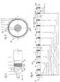
- Figure 1is a side view of an exemplary leaky coaxial antenna 10 according to an embodiment of the present invention.
- the coaxial antenna 10is coupleable to a connector 21 (not shown) on at least one end thereof.
- a second shield conductor 5is arranged discontinuously in the longitudinal direction of the antenna 10 defining uncovered portions of a first shield conductor 4 discontinuously in discrete positions in the longitudinal direction of the antenna.
- the leaky coaxial antenna 10comprises an inner conductor 1 which may be a metal or which may be metal wrapped around a plastic tube as described herein below in more detail.
- a dielectric 2is disposed around the inner or centre conductor 1, which dielectric may be any insulating material.
- dielectric 2is polytetrafluoroethylene (PTFE).
- PTFEpolytetrafluoroethylene
- dielectric 2may be expanded polytetrafluoroethylene (ePTFE).
- the leaky coaxial antenna 10has a conductive strip 3 disposed along a circumferential section of the dielectric 2 in longitudinal direction of the antenna to form a shielded segment 31 and an unshielded segment 32, wherein electromagnetic energy may pass to the outside of the antenna at said unshielded segment 32.
- Conductive strip 3may be a metal or metallized foil or another conductive layer.
- a first shield conductor 4is disposed around the dielectric 2 and the conductive strip 3, respectively, wherein the first shield conductor 4 has openings 41 distributed in longitudinal direction of the inner conductor 1.
- the first shield conductor 4is arranged in that electromagnetic energy passes through the openings 41.
- the first shield conductor 4is disposed -coaxially around the dielectric 2 and the conductive strip 3.
- the shield conductor 4may be a braid or a foil mesh. The important requirement for the shield conductor material 4 is that it contains openings through which electromagnetic energy can radiate or couple.
- a second shield conductor 5is disposed around the first shield conductor 4, wherein the second shield conductor 5 is adapted to cover at least a number of the openings 41 of the first shield conductor 4 in a shielded section, such as S1 to S12 shown in Figure 1 .
- a shielded sectionsuch as S1 to S12 shown in Figure 1 .
- the second shield conductor 5may be foil or any other suitable conductive material.
- a non-conductive jacket 6may be disposed over all of the components of coaxial antenna 10.
- the second shield conductor 5may be disposed underneath the first shield conductor 4, wherein the second shield conductor 5 is arranged to mask at least a number of the openings 41 of the first shield conductor 4 in the shielded sections S1 to S12. Accordingly, such shield conductor 5 is arranged discontinuously in the longitudinal direction of the antenna defining unmasked portions of the first shield conductor 4 in the longitudinal direction of the antenna.
- Such unmasked portions AS1 to AS12 of the first shield conductor 4are adapted in that electromagnetic energy passes through the unmasked portions AS1 to AS12.
- the unmasked portions AS1 to AS12are adapted to function as antenna sections:
- conductive strip 3may be disposed under, between, or over either or both of the first shield conductor 4 and the second shield conductor 5.
- the second shield conductor 5is arranged discontinuously in the longitudinal direction of the antenna 10 defining uncovered portions AS1 to AS12 of the first shield conductor 4 arranged discontinuously and at discrete locations in the longitudinal direction of the antenna.
- the same basic principlemay be applied when the second shield conductor 5 is disposed underneath the first shield conductor 4 defining unmasked portions AS1 to AS12 of the first shield conductor 4 in the longitudinal direction of the antenna.
- the second shield conductor 5comprises multiple tubular sections S1 to S12, as shown in the cross-sectional view of Figure 3 by means of reference numeral 5.
- Such multiple tubular sectionsare arranged discontinuously in the longitudinal direction of the antenna 10 defining the discontinuous or discrete uncovered or unmasked portions AS1 to AS12 between the tubular sections S1 to S12, which uncovered or unmasked portions AS1 to AS12 are also of tubular or ring form and function as antenna sections of the leaky coaxial cable 10.
- the shielded sections S1 to S12provide shield function (non-antenna function).
- each of the tubular sections S1 to S12is made rather great and is, for example, distinctly greater than the half of the wavelength of the operating frequencies.
- Surface wavesshall be enabled to dispread.
- the second shield conductor 5is arranged to be electrically coupled to the first shield conductor 4 within the shielded sections S1 to S12, at least with respect to the respective operating frequency when the antenna 10 is in operation.
- the first shield conductor 4 and the second shield conductor 5maintain galvanic contact to each other, so that the second shield conductor 5 is at ground potential when the first shield conductor 4 is coupled to ground potential.
- the first shield conductor 4radiates or couples electromagnetic energy to the outside of the shield conductor 4 over its whole length, i.e. over the whole length of the coaxial antenna as the first shield conductor 4 is arranged over the whole length of the antenna.
- This first shield conductor 4is thus arranged to provide antenna function of the leaky coaxial antenna 10.
- the second shield conductor 5is arranged to provide blocking function within discontinuous shielded sections S1 to S12 preventing the electromagnetic energy from passing to the outside of the antenna within the respective shielded section S1 to S12.
- each of the sections AS2 to AS11are arranged in a respective distance X 1 to X 10 from section AS1, which distances may vary as regards their relationship to one another.
- the uncovered or unmasked portions AS1 to AS12may have a distance between them in the longitudinal direction of the antenna that varies along the length of the antenna. Particularly, such distance may vary in a randomized manner along the length of the antenna for avoiding periodic resonances.
- the shown distances X 1 to X 10 as shown in Figure 1may be chosen in a randomized manner particularly avoiding equidistantly spaced uncovered or unmasked portions AS1 to AS12.
- the width L of the portions AS1 to AS12 and the distance between themmay be varied in order to tune the antenna to specific frequencies and to adjust return loss and coupling loss.
- the open structured shield conductor 4is also disposed coaxially around coaxial antenna 10, wherein the shield conductor 4 is disposed around the cable along its entire length so that conductivity is maintained longitudinally. Because of the open structure of the shield conductor 4, however, electromagnetic energy is allowed to couple or radiate through the open structure of the shield conductor 4 at the openings 41.
- the centre or inner conductor 1comprises a different structure in accordance with the principles as described in US 5 500 488 A .
- the inner conductor 1is arranged around a plastic core 11 wherein the inner conductor comprises two layers 12 and 13.
- the inner layer 12is in the form of an overlappingly and helically wrapped electrical conductive film, whereas the outer layer 13 is in the form of served wires that are in electrical contact with the inner layer 12.
- the layer 12may be in the form of a silver-plated copper film wrapped around the plastic core 11, wherein in the present embodiment a combination of twisted round silver-plated copper conductors 13 is applied over the copper film 12.
- the dielectric 14covers the inner conductor 1.
- Figure 4shows a side view of another exemplary leaky coaxial antenna according to another embodiment of the present invention showing concrete distances between the respective portions AS1 to AS10.
- the width L of the portions AS1 to AS10is kept constant over the shown length of the cable.
- the present inventiontherefore suggests a two-layer shield for improving the properties of a leaky coaxial antenna.
- both shield layersallow cable bending, however, since the second shield layer comprising the second shield conductor covers or masks the openings of the first shield layer comprising the first shield conductor over considerable parts of the cable length, the longitudinal loss of the coaxial transmission mode can be reduced significantly.
- the amount of transversal loss or radiation as well as the bandwidth and reach length of the leaky coaxial cablecan be controlled by the coverage of the first shield layer, or by the masking of the first shield layer, respectively, and the length of the uncovered or unmasked portions of the first shield layer (the openings of the second shield layer). This allows application of this invention to many applications. It has specific importance when high bandwidth and long reach length in combination with flexibility is required, such as in aerospace applications.
- Applicanthas produced examples of the inventive coaxial antenna and compared them to conventional coaxial cables. These examples and the results of the testing are reported below.
- a coaxial antenna according to the present inventionwas constructed as shown in figure 4 . The following tests were performed in order to test the practical effectiveness of the proposed invention.
- the bend radiuswas measured by wrapping the coaxial antenna of Figure 4 180° around mandrels of various diameters and measuring the change in characteristic impedance.
- the characteristic impedancewas measured using a Time Domain Reflectometer [Tektronix TDS 8000 with a TDR sampling module 80E04]. The results showed that the change in characteristic impedance was less than 1 Ohm for mandrel diameters of greater than or equal to 32 mm. This test gave a good indication that the coaxial antenna could be used in applications requiring bends and/or some flexibility.
- the frequency response of the coaxial antenna of Example 1was measured using an Agilent 8753ES Vector Network Analyzer. Both Insertion Loss S21 and Return Loss S11 were measured over a frequency range of 300 kHz to 6 GHz. To get a baseline performance level these measurements were first performed with the coax antenna of Example 1 before openings were put into the outer second shield conductor (longitudinal attenuation) and second after such openings were introduced into the coax antenna (longitudinal and transversal attenuation). The results were as follows: the baseline (non-antenna) cable had longitudinal Insertion Loss of 0.19 dB/m at 2.5 GHz and 0.31 dB/m at 6 GHz.
- a WLAN networkwas established using the coaxial antenna of this example between two computers.
- the WLAN Access Point[SMC EliteConnect Universal Wireless Access Point SMC2555W-AG] was connected to 60 m of the coaxial antenna of this example.
- a 10 m sectionwas suspended about 2 metres above the ground and a receiver was positioned at various points beneath the suspended antenna and the performance was measured.
- the receivercomprised a mobile computer [Dell ® Lattitude] with a wireless LAN card [SMC EliteConnect Universal Wireless Card-bus Adapter SMC2536W-AG].
- the WLAN link qualitywas measured using software that came with the WLAN antenna and indicated a maximum link quality within 5 metre distance from the suspended antenna.
Landscapes
- Engineering & Computer Science (AREA)
- Aviation & Aerospace Engineering (AREA)
- Remote Sensing (AREA)
- Physics & Mathematics (AREA)
- Astronomy & Astrophysics (AREA)
- General Physics & Mathematics (AREA)
- Computer Networks & Wireless Communication (AREA)
- Signal Processing (AREA)
- Waveguide Aerials (AREA)
- Waveguides (AREA)
- Details Of Aerials (AREA)
Abstract
Description
- The present invention relates to a leaky coaxial antenna comprising an inner conductor, a dielectric around the inner conductor and a shield conductor disposed around the dielectric, the shield conductor having openings distributed in longitudinal direction of the inner conductor and being adapted in that electromagnetic energy passes through the openings. Particularly, such leaky coaxial antenna may be used in airplanes and in other applications.
- Leaky and/or radiating coaxial cables may be employed as longitudinal antennas in confined spaces like tunnels, mines, buildings, and/or in other stretched-out applications involving a narrow lateral corridor (such as railroads and highways). In modern applications, such cables may be employed in stretched-out vehicles such as airplanes, were there is a need for one- or two-way communication. Leaky coaxial cables support surface waves, were a fraction of the power is radiated radially. Leaky coaxial cables operate in a radiating or a coupling mode. These modes correspond to an in-phase addition of all contributing apertures.
- Most of the known leaky and/or radiating coaxial cables are heavy, large in diameter, and inflexible. Historically this has not been a problem, however, because the applications in which they are used, such as some of those mentioned above, do not require either lightweight or flexible cables. However, particularly for use in airplanes, for example, such drawbacks may be disadvantageous.
US 4 599 121US 5 936 203 AUS 4 339 733DE 26 36 523 A1 andUS 4 129 841- None of the known leaky and/or radiating coaxial cables, such as those embodied in some of the above references, meet all requirements for use in aerospace applications. While flexible designs using an open braid structure have limited bandwidth and high longitudinal losses, designs with a ridged outer conductor having openings have a large bend radius and lack flexibility. In particular, a leaky/radiating coaxial cable intended for use as a distributed antenna for wireless applications like WLAN and GSM in airplanes must meet many specific requirements. These requirements include that it must be flexible (have a bend radius of 32 mm with less than 1 Ohm impedance change), high bandwidth and wideband (400 MHz up to 6 GHz), lightweight (190 g/m), low longitudinal loss (attenuation of less than 0.36 dB/m at 6 GHz) in order to support operation within the frequency band up to antenna lengths of 60 m, for example. The leaky/radiating coaxial cable for use in an airplane must be flexible because it will be installed inside the airplane where many other obstacles require that the antenna cannot be run in a straight line. It must have high frequency response because many of the wireless communication standards operate at several GHz. It must have high bandwidth because each of the wireless communication standards operate in its own frequency band within one antenna. It must be lightweight to comply with airline specifications with the aim to minimize airplane weight. It must have low longitudinal loss to allow enough reach length while having sufficient radiation loss to function as a receiving and/or transmitting antenna. Finally, the radiation loss should be homogenous along the length and allow a sectional circumferential radiation pattern to maintain the specified noise immunity requirements defined by the application, for example an airplane specification.
- The object of the present invention is, therefore, to provide a leaky coaxial antenna which is capable to improve at least some of the above-mentioned drawbacks of existing solutions.
- This object is solved by a leaky coaxial antenna according to the features of
claim 1 orclaim 2. Embodiments of a leaky coaxial antenna according to the invention are evident from the dependent claims. - Particularly, according to a first aspect of the invention, a leaky coaxial antenna comprises an inner conductor, a dielectric around the inner conductor, and a first shield conductor disposed around the dielectric, the first shield conductor having openings distributed in longitudinal direction of the inner conductor and being adapted in that electromagnetic energy passes through the openings. A second shield conductor is disposed around the first shield conductor, wherein the second shield conductor is adapted to cover at least a number of the openings of the first shield conductor in a shielded section for preventing the electromagnetic energy from passing to the outside of the antenna within the shielded section. Moreover, the second shield conductor is arranged discontinuously in the longitudinal direction of the antenna defining tubular shield sections and uncovered portions of the first shield conductor in the longitudinal direction of the antenna which are adapted in that electromagnetic energy passes through the uncovered portions. Each of the tubular shield sections has an axial length distinctly greater than half of a wavelength of operating frequencies.
- According to another aspect of the present invention, the second shield conductor is disposed underneath the first shield conductor, wherein the second shield conductor is adapted to mask at least a number of the openings of the first shield conductor in the shielded section for preventing the electromagnetic energy from passing to the outside of the antenna within the shielded section. Furthermore, the second shield conductor is arranged discontinuously in the longitudinal direction of the antenna defining unmasked portions of the first shield conductor in the longitudinal direction of the antenna which are adapted in that electromagnetic energy passes through the unmasked portions.
- Thus, the present invention suggests a two-layer shield, comprising the first shield conductor and the second shield conductor for improving the properties of a leaky coaxial antenna, as referred to in the introductory part of the description. Particularly, both shield layers allow cable bending, however, since the second shield layer comprising the second shield conductor covers or masks the openings of the first shield layer comprising the first shield conductor over considerable parts of the cable length, the longitudinal loss of the coaxial transmission mode can be reduced significantly. This allows a combination of a flexible design with low longitudinal loss. The amount of transversal loss or radiation as well as the bandwidth and reach length of the leaky coaxial cable can be controlled by different attributes: the coverage of the second shield layer on top of the first shield layer, or by the masking of the second shield layer underneath the first shield layer, respectively, and the length of the uncovered or unmasked portions of the first shield layer (the openings of the second shield layer). Furthermore, the openings of the first shield layer (e.g. width and/or number) may be varied accordingly. This allows application of this invention to many applications. It has specific importance when high bandwidth and long reach length in combination with flexibility is required, such as in aerospace applications.
- According to an embodiment of the present invention, the second shield conductor comprises multiple tubular sections which are arranged discontinuously in the longitudinal direction of the antenna defining the uncovered or unmasked portions, respectively, of the first shield conductor between the tubular sections.
- In accordance with another embodiment of the present invention, the second shield conductor is arranged to be electrically coupled to the first shield conductor within the shielded section at least when the antenna is in operation. Thus, when the first shield conductor is connected to ground potential, the second shield conductor will also be connected to ground potential for performing shield function. According to an embodiment, the first shield conductor and the second shield conductor maintain galvanic contact to each other, so that both shield conductors are connected directly to one another. On the other hand, the first shield conductor may also be connected to the second shield conductor via materials having capacitive behaviour for coupling the second shield conductor to the first shield conductor via capacitive coupling. Such coupling is particularly arranged with respect to the operating frequencies of the leaky coaxial antenna. In this concern, for example a dielectric material arranged between the first shield conductor and the second shield conductor may serve as capacitive coupling element.
- According to another embodiment of the present invention, a conductive strip is longitudinally disposed along a circumferential section of the dielectric to form a shielded segment of said openings and an unshielded segment of said openings, wherein the electromagnetic energy passes through the openings at said unshielded segment of said openings. Such conductive strip may be applied, for example, for focussing the electromagnetic energy into a preferred direction of the leaky coaxial antenna. Furthermore, such conductive strip may be used for concentrating the electromagnetic energy at certain locations of the antenna and reduces longitudinal loss.
- According to yet another embodiment of the present invention, the first shield conductor and the second shield conductor are electrically coupled through the conductive strip.
- The first shield conductor may comprise an open structure of wire conductors which do not cover the entire surface of the layer underneath. According to another embodiment, the first shield conductor comprises an open structured conductive foil mesh. Furthermore, the inner conductor may comprise a metal conductor which is wrapped around a plastic core. Such plastic core or plastic tube is preferably comprised of FEP (fluoroethylene propylene). The dielectric is preferably polytetrafluoroethylene, and most preferably expanded polytetrafluoroethylene. Preferably, a non-conductive jacket is disposed around the second shield conductor and the first shield conductor.
- In a particular embodiment, the leaky coaxial antenna of the present invention may comprise the base coaxial cable described in
US 5 500 488 A andEP 0 635 850 A1 which is modified according to the principles of the present invention as described herein. That is, the basic principles described herein may be applied to such cable. Particularly, the inner conductor may be arranged around a plastic core wherein the inner conductor further comprises two layers with an inner layer in the form of an overlappingly and helically wrapped electrical conductive film and an outer layer in the form of served wires that are in electrical contact with the inner layer. - According to an embodiment of the present invention, the uncovered or unmasked portions, respectively, of the first shield conductor which form the sections of the coaxial antenna performing the antenna function have a distance between them in longitudinal direction of the antenna that varies along the length of the antenna. Particularly, the distance may vary in a randomized manner along the length of the antenna avoiding periodic resonances. Such periodic resonances can, if they occur, reduce performance of the leaky coaxial antenna. In this concern, varying in a randomized manner means a variable non-predetermined structure or legality of the distances between the uncovered or unmasked portions, respectively, of the first shield conductor.
- According to another embodiment of the invention the uncovered or unmasked portions, respectively, of the first shield conductor have a width in longitudinal direction of the antenna that varies along the length of the antenna. Particularly, the uncovered or unmasked portions, respectively, may have a width that gets wider as the cable is traversed from the transmit end to the receive end in order to produce a more homogeneous radiation power loss along the length of the antenna.
- According to yet another embodiment of the invention, a combination of varying the widths of the uncovered or unmasked portions, respectively, and varying distances between the portions is invoked in order to, in a combinative effect, produce homogeneous loss and to avoid periodic resonances that can reduce performance.
- The various components of the inventive leaky coaxial antenna can be disposed in any suitable order. For example, the coaxial antenna has a weight of about 190 g/m or less (although depending on the ultimate application, weight may not be critical), a bend radius is less than 32 mm, a bandwidth from 400 MHz to 6 GHz, and a longitudinal attenuation of less than 0.36 dB per meter at a frequency of 6 GHz.
- Further embodiments and advantageous features of the present invention are evident from the dependent claims.
- The invention will be better understood by reference to the following description of embodiments of the invention taken on conjunction with the accompanying drawings, wherein
- Figure 1
- shows a side view of an exemplary leaky coaxial antenna according to an embodiment of the present invention,
- Figure 2
- is a side view of an exemplary leaky coaxial antenna according to an embodiment of the present invention showing each of the various components disposed according to an embodiment of the invention,
- Figure 3
- is a cross-sectional view of the exemplary leaky coaxial antenna of
Figure 2 , - Figure 4
- is a side view of another exemplary leaky coaxial antenna assembly according to another embodiment of the present invention,
- Figure 5
- shows parts of another embodiment of a leaky coaxial antenna according to the invention.
- The invention will now be described with particular reference to embodiments of the invention illustrated in the accompanying Figures.
Figure 1 is a side view of an exemplary leakycoaxial antenna 10 according to an embodiment of the present invention. Thecoaxial antenna 10 is coupleable to a connector 21 (not shown) on at least one end thereof. Asecond shield conductor 5 is arranged discontinuously in the longitudinal direction of theantenna 10 defining uncovered portions of afirst shield conductor 4 discontinuously in discrete positions in the longitudinal direction of the antenna. - More details of the leaky coaxial antenna according to the invention are shown with reference to
Figures 2 and 3 . The leakycoaxial antenna 10 comprises aninner conductor 1 which may be a metal or which may be metal wrapped around a plastic tube as described herein below in more detail. A dielectric 2 is disposed around the inner orcentre conductor 1, which dielectric may be any insulating material. For example,dielectric 2 is polytetrafluoroethylene (PTFE). Particularly, dielectric 2 may be expanded polytetrafluoroethylene (ePTFE). - According to an embodiment, the leaky
coaxial antenna 10 has aconductive strip 3 disposed along a circumferential section of the dielectric 2 in longitudinal direction of the antenna to form a shieldedsegment 31 and anunshielded segment 32, wherein electromagnetic energy may pass to the outside of the antenna at saidunshielded segment 32.Conductive strip 3 may be a metal or metallized foil or another conductive layer. By disposingconductive strip 3 along the length ofcoaxial antenna 10 covering just a section of the outer surface thereof, electromagnetic energy couples or radiates out of theunshielded segment 32 in a direction away fromconductive strip 3. In this manner, the electromagnetic energy and radiation pattern may be focussed in particular directions, thereby controlling the directivity of the coaxial antenna. This is particularly important if the near field and/or far field electromagnetic field density needs to be controlled in sensitive areas such as areas that contain electromagnetic interference (EMI) sensitive equipment. - A
first shield conductor 4 is disposed around thedielectric 2 and theconductive strip 3, respectively, wherein thefirst shield conductor 4 hasopenings 41 distributed in longitudinal direction of theinner conductor 1. Thus, thefirst shield conductor 4 is arranged in that electromagnetic energy passes through theopenings 41. Thefirst shield conductor 4 is disposed -coaxially around thedielectric 2 and theconductive strip 3. Theshield conductor 4 may be a braid or a foil mesh. The important requirement for theshield conductor material 4 is that it contains openings through which electromagnetic energy can radiate or couple. Further, asecond shield conductor 5 is disposed around thefirst shield conductor 4, wherein thesecond shield conductor 5 is adapted to cover at least a number of theopenings 41 of thefirst shield conductor 4 in a shielded section, such as S1 to S12 shown inFigure 1 . In these shielded sections S1 to S12 the electromagnetic energy is prevented from passing to or from the outside of the antenna within the respective shielded section. Thesecond shield conductor 5 may be foil or any other suitable conductive material. Anon-conductive jacket 6 may be disposed over all of the components ofcoaxial antenna 10. - The various components of leaky
coaxial antenna 10 of the present invention are illustrated in the Figures in respective embodiments. For example, thesecond shield conductor 5 may be disposed underneath thefirst shield conductor 4, wherein thesecond shield conductor 5 is arranged to mask at least a number of theopenings 41 of thefirst shield conductor 4 in the shielded sections S1 to S12. Accordingly,such shield conductor 5 is arranged discontinuously in the longitudinal direction of the antenna defining unmasked portions of thefirst shield conductor 4 in the longitudinal direction of the antenna. Such unmasked portions AS1 to AS12 of thefirst shield conductor 4 are adapted in that electromagnetic energy passes through the unmasked portions AS1 to AS12. Thus, the unmasked portions AS1 to AS12 are adapted to function as antenna sections: Moreover,conductive strip 3 may be disposed under, between, or over either or both of thefirst shield conductor 4 and thesecond shield conductor 5. - In accordance with the embodiment of
Figure 1 , thesecond shield conductor 5 is arranged discontinuously in the longitudinal direction of theantenna 10 defining uncovered portions AS1 to AS12 of thefirst shield conductor 4 arranged discontinuously and at discrete locations in the longitudinal direction of the antenna. The same basic principle may be applied when thesecond shield conductor 5 is disposed underneath thefirst shield conductor 4 defining unmasked portions AS1 to AS12 of thefirst shield conductor 4 in the longitudinal direction of the antenna. Particularly, according toFigure 1 , thesecond shield conductor 5 comprises multiple tubular sections S1 to S12, as shown in the cross-sectional view ofFigure 3 by means ofreference numeral 5. Such multiple tubular sections are arranged discontinuously in the longitudinal direction of theantenna 10 defining the discontinuous or discrete uncovered or unmasked portions AS1 to AS12 between the tubular sections S1 to S12, which uncovered or unmasked portions AS1 to AS12 are also of tubular or ring form and function as antenna sections of the leakycoaxial cable 10. In contrast, the shielded sections S1 to S12 provide shield function (non-antenna function). - Particularly, the axial length of each of the tubular sections S1 to S12 is made rather great and is, for example, distinctly greater than the half of the wavelength of the operating frequencies. Surface waves shall be enabled to dispread.
- In order to provide shield function, the
second shield conductor 5 is arranged to be electrically coupled to thefirst shield conductor 4 within the shielded sections S1 to S12, at least with respect to the respective operating frequency when theantenna 10 is in operation. Particularly, thefirst shield conductor 4 and thesecond shield conductor 5 maintain galvanic contact to each other, so that thesecond shield conductor 5 is at ground potential when thefirst shield conductor 4 is coupled to ground potential. Thus, thefirst shield conductor 4 radiates or couples electromagnetic energy to the outside of theshield conductor 4 over its whole length, i.e. over the whole length of the coaxial antenna as thefirst shield conductor 4 is arranged over the whole length of the antenna. Thisfirst shield conductor 4 is thus arranged to provide antenna function of the leakycoaxial antenna 10. In contrast, thesecond shield conductor 5 is arranged to provide blocking function within discontinuous shielded sections S1 to S12 preventing the electromagnetic energy from passing to the outside of the antenna within the respective shielded section S1 to S12. - Therefore, the electromagnetic energy of
coaxial antenna 10 is transmitted through the uncovered or unmasked portions AS1 to AS12 where thesecond shield conductor 5 provides openings. The width L of these uncovered or unmasked portions AS1 to AS12 may be varied in order to tune the antenna to specific frequencies and to adjust return loss and coupling loss. Moreover, each of the sections AS2 to AS11 are arranged in a respective distance X1 to X10 from section AS1, which distances may vary as regards their relationship to one another. Particularly, the uncovered or unmasked portions AS1 to AS12 may have a distance between them in the longitudinal direction of the antenna that varies along the length of the antenna. Particularly, such distance may vary in a randomized manner along the length of the antenna for avoiding periodic resonances. Thus, the shown distances X1 to X10 as shown inFigure 1 may be chosen in a randomized manner particularly avoiding equidistantly spaced uncovered or unmasked portions AS1 to AS12. In combination, the width L of the portions AS1 to AS12 and the distance between them may be varied in order to tune the antenna to specific frequencies and to adjust return loss and coupling loss. - Because signals must be carried longitudinally down
coaxial antenna 10, the open structuredshield conductor 4 is also disposed coaxially aroundcoaxial antenna 10, wherein theshield conductor 4 is disposed around the cable along its entire length so that conductivity is maintained longitudinally. Because of the open structure of theshield conductor 4, however, electromagnetic energy is allowed to couple or radiate through the open structure of theshield conductor 4 at theopenings 41. - In
Figure 5 , there is shown a side view of parts of another exemplary leaky-coaxial antenna according to an embodiment of the present invention. According to this embodiment, the centre orinner conductor 1 comprises a different structure in accordance with the principles as described inUS 5 500 488 Ainner conductor 1 is arranged around aplastic core 11 wherein the inner conductor comprises twolayers inner layer 12 is in the form of an overlappingly and helically wrapped electrical conductive film, whereas theouter layer 13 is in the form of served wires that are in electrical contact with theinner layer 12. Thelayer 12 may be in the form of a silver-plated copper film wrapped around theplastic core 11, wherein in the present embodiment a combination of twisted round silver-platedcopper conductors 13 is applied over thecopper film 12. The dielectric 14 covers theinner conductor 1. With such construction a wide-band high frequency compatible electrical coaxial cable may be provided which combines wide-band high frequency compatible transmission properties which satisfy the need for a low-attenuation coaxial cable which optimizes desired electrical and mechanical properties as well as manufacturing costs, in combination with antenna properties as described herein. Moreover, low cable weight and high flexibility may be provided. Figure 4 shows a side view of another exemplary leaky coaxial antenna according to another embodiment of the present invention showing concrete distances between the respective portions AS1 to AS10. According to this example, the width L of the portions AS1 to AS10 is kept constant over the shown length of the cable.- The present invention therefore suggests a two-layer shield for improving the properties of a leaky coaxial antenna. Particularly, both shield layers allow cable bending, however, since the second shield layer comprising the second shield conductor covers or masks the openings of the first shield layer comprising the first shield conductor over considerable parts of the cable length, the longitudinal loss of the coaxial transmission mode can be reduced significantly. This allows a combination of a flexible design with low longitudinal loss. The amount of transversal loss or radiation as well as the bandwidth and reach length of the leaky coaxial cable can be controlled by the coverage of the first shield layer, or by the masking of the first shield layer, respectively, and the length of the uncovered or unmasked portions of the first shield layer (the openings of the second shield layer). This allows application of this invention to many applications. It has specific importance when high bandwidth and long reach length in combination with flexibility is required, such as in aerospace applications.
- Applicant has produced examples of the inventive coaxial antenna and compared them to conventional coaxial cables. These examples and the results of the testing are reported below.
- A coaxial antenna according to the present invention was constructed as shown in
figure 4 . The following tests were performed in order to test the practical effectiveness of the proposed invention. - The bend radius was measured by wrapping the coaxial antenna of
Figure 4 180° around mandrels of various diameters and measuring the change in characteristic impedance. The characteristic impedance was measured using a Time Domain Reflectometer [Tektronix TDS 8000 with a TDR sampling module 80E04]. The results showed that the change in characteristic impedance was less than 1 Ohm for mandrel diameters of greater than or equal to 32 mm. This test gave a good indication that the coaxial antenna could be used in applications requiring bends and/or some flexibility. - The frequency response of the coaxial antenna of Example 1 was measured using an Agilent 8753ES Vector Network Analyzer. Both Insertion Loss S21 and Return Loss S11 were measured over a frequency range of 300 kHz to 6 GHz. To get a baseline performance level these measurements were first performed with the coax antenna of Example 1 before openings were put into the outer second shield conductor (longitudinal attenuation) and second after such openings were introduced into the coax antenna (longitudinal and transversal attenuation). The results were as follows: the baseline (non-antenna) cable had longitudinal Insertion Loss of 0.19 dB/m at 2.5 GHz and 0.31 dB/m at 6 GHz. After the openings were introduced the combination of longitudinal and transversal loss was measured to be 0.24 dB/m at 2.5 GHz and 0.57 dB/m at 6 GHz. Return Loss of the leaky line antenna was measured to be less than -18 dB for frequencies less than 6 GHz. In addition, a Transfer Impedance measurement was performed to derive the antenna efficiency using a Vector Network Analyzer ZVCE from Rhode & Schwarz. The test was performed in a shielded room. The wire injection method described in the International Electrotechnical Commission standards document IEC 61196-1 was implemented over a frequency range of 20 kHz to 3 GHz. The test sample was a 0.5 m long coaxial antenna with one opening. Both ends are terminated into brass fixtures to provide defined grounding conditions. The antenna efficiency was measured -15 dB at 800 MHz and -10 dB at 2.5 GHz. These experiments showed that the radiating/leaky coaxial antenna of Example 1 exhibited high bandwidth, i.e. 400 MHz to 6 GHz.
- Another experiment performed was to hook up the coaxial antenna of Example 1 in a practical situation representing a system in use: a WLAN network was established using the coaxial antenna of this example between two computers. The WLAN Access Point [SMC EliteConnect Universal Wireless Access Point SMC2555W-AG] was connected to 60 m of the coaxial antenna of this example. A 10 m section was suspended about 2 metres above the ground and a receiver was positioned at various points beneath the suspended antenna and the performance was measured. The receiver comprised a mobile computer [Dell® Lattitude] with a wireless LAN card [SMC EliteConnect Universal Wireless Card-bus Adapter SMC2536W-AG]. The WLAN link quality was measured using software that came with the WLAN antenna and indicated a maximum link quality within 5 metre distance from the suspended antenna.
Claims (13)
- A leaky coaxial antenna (10) comprising:- an inner conductor (1),- a dielectric (2) around the inner conductor (1),- a first shield conductor (4) disposed around the dielectric (2), the first shield conductor having openings (41) distributed in longitudinal direction of the inner conductor (1) and being adapted in that electromagnetic energy passes through the openings (41),
characterized by- a second shield conductor (5) disposed around the first shield conductor (4), the second shield conductor (5) being adapted to cover at least a number of the openings (41) of the first shield conductor in a shielded section (S1 - S12),wherein the second shield conductor (5) is arranged discontinuously in the longitudinal direction of the antenna (10) defining tubular shield sections (S1 - S12) and uncovered portions (AS1 - AS12) of the first shield conductor (4) in the longitudinal direction of the antenna, which are adapted in that electromagnetic energy passes through the uncovered portions (AS1 - AS12), and
wherein each of the tubular shield sections (S1-S12) is having an axial length distinctly greater than half of a wavelength of operating frequencies for preventing the electromagnetic energy from passing to the outside of the antenna within each of the tubular shield sections (S1 - S12). - A leaky coaxial antenna (10) comprising:an inner conductor (1),a dielectric (2) around the inner conductor (1),a first shield conductor (4) disposed around the dielectric (2), the first shield conductor having openings (41) distributed in longitudinal direction of the inner conductor (1) and being adapted in that electromagnetic energy passes through the openings (41),
characterized bya second shield conductor (5) disposed underneath the first shield conductor (4), the second shield conductor (5) being adapted to mask at least a number of the openings (41) of the first shield conductor in a shielded section (S1 - S12) for preventing the electromagnetic energy from passing to the outside of the antenna within the shielded section (S1 - S12),wherein the second shield conductor (5) is arranged discontinuously in the longitudinal direction of the antenna (10) defining unmasked portions (AS1 - AS12) of the first shield conductor (4) in the longitudinal direction of the antenna which are adapted in that electromagnetic energy passes through the unmasked portions (AS1 - AS12). - The leaky coaxial antenna of claim 1 or 2, wherein
the second shield conductor (5) comprises multiple tubular sections (5, S1 - S12) arranged discontinuously in the longitudinal direction of the antenna (10) defining the uncovered or unmasked portions (AS1 - AS12), respectively, of the first shield conductor (4) between the tubular sections (S1 - S12). - The leaky coaxial antenna of one of claims 1 to 3, wherein
the second shield conductor (5) is arranged to be electrically coupled to the first shield conductor (4) within the shielded section (S1 - S12) at least when the antenna (10) is in operation. - The leaky coaxial antenna of one of claims 1 to 4, wherein
the first shield conductor (4) and the second shield conductor (5) maintain galvanic contact to each other. - The leaky coaxial antenna of one of claims 1 to 5, further comprising a conductive strip (3) longitudinally disposed along a circumferential section of the dielectric (2) to form a shielded segment (31) of said openings (41) and an unshielded segment (32) of said openings (41), wherein said electromagnetic energy passes trough said openings (41) at said unshielded segment (32) of said openings.
- The leaky coaxial antenna of claim 6, wherein
the first shield conductor (4) and the second shield conductor (5) are electrically coupled through said conductive strip (3). - The leaky coaxial antenna of one of claims 1 to 7, wherein
the first shield conductor (4) comprises an open structure of wire conductors which do not cover the entire surface of the layer (2, 3) underneath. - The leaky coaxial antenna of one of claims 1 to 7, wherein
the first shield conductor (4) comprises an open structured conductive foil, a conductive mesh, served wires, or braided wires. - The leaky coaxial antenna of one of claims 1 to 9, wherein
the uncovered or unmasked portions (AS1 - AS12), respectively, of the first shield conductor (4) have a distance (X1 - X10) between them in longitudinal direction of the antenna (10) that varies along the length of the antenna (10), particularly varies in a randomized manner along the length of the antenna avoiding periodic resonances. - The leaky coaxial antenna of one of claims 1 to 10, wherein
the uncovered or unmasked portions (AS1 - AS12), respectively, of the first shield conductor (4) have a width (L) in longitudinal direction of the antenna (10) that varies along the length of the antenna (10). - The leaky coaxial antenna of one of claims 1 to 11, wherein
the inner conductor (1) comprises a metal conductor (12, 13) wrapped around a plastic core (11). - The leaky coaxial antenna of one of claims 1 to 12, wherein
the inner conductor (1) is arranged around a plastic core (11) and wherein the inner conductor further comprises two layers (12, 13) with an inner layer (12) in the form of an overlapping and helically wrapped electrical conductive film and an outer layer (13) in the form of served wires that are in electrical contact with the inner layer (12).
Priority Applications (14)
| Application Number | Priority Date | Filing Date | Title |
|---|---|---|---|
| AT06002185TATE400909T1 (en) | 2006-02-02 | 2006-02-02 | ANTENNA WITH RADIating COAXIAL CABLE |
| DE602006001728TDE602006001728D1 (en) | 2006-02-02 | 2006-02-02 | Antenna with radiating coaxial cable |
| EP06002185AEP1816704B1 (en) | 2006-02-02 | 2006-02-02 | Leaky coaxial antenna |
| PL06002185TPL1816704T3 (en) | 2006-02-02 | 2006-02-02 | Leaky coaxial antenna |
| ES06002185TES2310378T3 (en) | 2006-02-02 | 2006-02-02 | ISSUER COAXIAL ANTENNA. |
| CA2641124ACA2641124C (en) | 2006-02-02 | 2007-01-23 | Leaky coaxial antenna |
| US12/162,191US7872611B2 (en) | 2006-02-02 | 2007-01-23 | Leaky coaxial antenna |
| BRPI0707369-0ABRPI0707369A2 (en) | 2006-02-02 | 2007-01-23 | leaky coaxial antenna |
| RU2008135436/09ARU2378747C1 (en) | 2006-02-02 | 2007-01-23 | Leaky coaxial antenna |
| ZA200804639AZA200804639B (en) | 2006-02-02 | 2007-01-23 | Leaky coaxial antenna |
| PCT/EP2007/000554WO2007087998A1 (en) | 2006-02-02 | 2007-01-23 | Leaky coaxial antenna |
| AU2007211668AAU2007211668B2 (en) | 2006-02-02 | 2007-01-23 | Leaky coaxial antenna |
| KR1020087019052AKR101067831B1 (en) | 2006-02-02 | 2007-01-23 | Leakage coaxial antenna |
| JP2008552721AJP4829314B2 (en) | 2006-02-02 | 2007-01-23 | Leaky coaxial antenna |
Applications Claiming Priority (1)
| Application Number | Priority Date | Filing Date | Title |
|---|---|---|---|
| EP06002185AEP1816704B1 (en) | 2006-02-02 | 2006-02-02 | Leaky coaxial antenna |
Publications (2)
| Publication Number | Publication Date |
|---|---|
| EP1816704A1 EP1816704A1 (en) | 2007-08-08 |
| EP1816704B1true EP1816704B1 (en) | 2008-07-09 |
Family
ID=36001154
Family Applications (1)
| Application Number | Title | Priority Date | Filing Date |
|---|---|---|---|
| EP06002185ANot-in-forceEP1816704B1 (en) | 2006-02-02 | 2006-02-02 | Leaky coaxial antenna |
Country Status (14)
| Country | Link |
|---|---|
| US (1) | US7872611B2 (en) |
| EP (1) | EP1816704B1 (en) |
| JP (1) | JP4829314B2 (en) |
| KR (1) | KR101067831B1 (en) |
| AT (1) | ATE400909T1 (en) |
| AU (1) | AU2007211668B2 (en) |
| BR (1) | BRPI0707369A2 (en) |
| CA (1) | CA2641124C (en) |
| DE (1) | DE602006001728D1 (en) |
| ES (1) | ES2310378T3 (en) |
| PL (1) | PL1816704T3 (en) |
| RU (1) | RU2378747C1 (en) |
| WO (1) | WO2007087998A1 (en) |
| ZA (1) | ZA200804639B (en) |
Families Citing this family (54)
| Publication number | Priority date | Publication date | Assignee | Title |
|---|---|---|---|---|
| KR101043855B1 (en)* | 2009-01-13 | 2011-06-22 | 엘에스전선 주식회사 | Cable Type Broadband Antenna System |
| GB0914502D0 (en) | 2009-08-19 | 2009-09-30 | Rolls Royce Plc | Electrical conductor paths |
| CN102394329A (en)* | 2011-10-17 | 2012-03-28 | 江苏俊知技术有限公司 | Outer conductor leaky coaxial cable with novel double-layer winding |
| BR112016015619B1 (en)* | 2014-01-20 | 2022-03-15 | Telefonaktiebolaget Lm Ericsson (Publ) | ANTENNA SYSTEM AND METHOD TO PROVIDE COVERAGE FOR MIMO COMMUNICATION |
| RU2559755C1 (en)* | 2014-01-30 | 2015-08-10 | Юрий Пантелеевич Лепеха | Wideband antenna device based on radiating coaxial cable |
| US9601444B2 (en)* | 2014-02-27 | 2017-03-21 | Tektronix, Inc. | Cable mounted modularized signal conditioning apparatus system |
| US9973299B2 (en) | 2014-10-14 | 2018-05-15 | At&T Intellectual Property I, L.P. | Method and apparatus for adjusting a mode of communication in a communication network |
| US9312919B1 (en) | 2014-10-21 | 2016-04-12 | At&T Intellectual Property I, Lp | Transmission device with impairment compensation and methods for use therewith |
| US9997819B2 (en) | 2015-06-09 | 2018-06-12 | At&T Intellectual Property I, L.P. | Transmission medium and method for facilitating propagation of electromagnetic waves via a core |
| US10009067B2 (en) | 2014-12-04 | 2018-06-26 | At&T Intellectual Property I, L.P. | Method and apparatus for configuring a communication interface |
| US10243784B2 (en) | 2014-11-20 | 2019-03-26 | At&T Intellectual Property I, L.P. | System for generating topology information and methods thereof |
| US9544006B2 (en) | 2014-11-20 | 2017-01-10 | At&T Intellectual Property I, L.P. | Transmission device with mode division multiplexing and methods for use therewith |
| US9461706B1 (en) | 2015-07-31 | 2016-10-04 | At&T Intellectual Property I, Lp | Method and apparatus for exchanging communication signals |
| US9954287B2 (en) | 2014-11-20 | 2018-04-24 | At&T Intellectual Property I, L.P. | Apparatus for converting wireless signals and electromagnetic waves and methods thereof |
| US9876570B2 (en) | 2015-02-20 | 2018-01-23 | At&T Intellectual Property I, Lp | Guided-wave transmission device with non-fundamental mode propagation and methods for use therewith |
| US10224981B2 (en) | 2015-04-24 | 2019-03-05 | At&T Intellectual Property I, Lp | Passive electrical coupling device and methods for use therewith |
| US9705561B2 (en) | 2015-04-24 | 2017-07-11 | At&T Intellectual Property I, L.P. | Directional coupling device and methods for use therewith |
| US9490869B1 (en) | 2015-05-14 | 2016-11-08 | At&T Intellectual Property I, L.P. | Transmission medium having multiple cores and methods for use therewith |
| US9871282B2 (en) | 2015-05-14 | 2018-01-16 | At&T Intellectual Property I, L.P. | At least one transmission medium having a dielectric surface that is covered at least in part by a second dielectric |
| US10650940B2 (en)* | 2015-05-15 | 2020-05-12 | At&T Intellectual Property I, L.P. | Transmission medium having a conductive material and methods for use therewith |
| US10679767B2 (en) | 2015-05-15 | 2020-06-09 | At&T Intellectual Property I, L.P. | Transmission medium having a conductive material and methods for use therewith |
| US9917341B2 (en) | 2015-05-27 | 2018-03-13 | At&T Intellectual Property I, L.P. | Apparatus and method for launching electromagnetic waves and for modifying radial dimensions of the propagating electromagnetic waves |
| US9866309B2 (en) | 2015-06-03 | 2018-01-09 | At&T Intellectual Property I, Lp | Host node device and methods for use therewith |
| US9912381B2 (en) | 2015-06-03 | 2018-03-06 | At&T Intellectual Property I, Lp | Network termination and methods for use therewith |
| US9913139B2 (en) | 2015-06-09 | 2018-03-06 | At&T Intellectual Property I, L.P. | Signal fingerprinting for authentication of communicating devices |
| US9820146B2 (en) | 2015-06-12 | 2017-11-14 | At&T Intellectual Property I, L.P. | Method and apparatus for authentication and identity management of communicating devices |
| US9640850B2 (en) | 2015-06-25 | 2017-05-02 | At&T Intellectual Property I, L.P. | Methods and apparatus for inducing a non-fundamental wave mode on a transmission medium |
| US9865911B2 (en) | 2015-06-25 | 2018-01-09 | At&T Intellectual Property I, L.P. | Waveguide system for slot radiating first electromagnetic waves that are combined into a non-fundamental wave mode second electromagnetic wave on a transmission medium |
| US10044409B2 (en) | 2015-07-14 | 2018-08-07 | At&T Intellectual Property I, L.P. | Transmission medium and methods for use therewith |
| US9853342B2 (en) | 2015-07-14 | 2017-12-26 | At&T Intellectual Property I, L.P. | Dielectric transmission medium connector and methods for use therewith |
| US9847566B2 (en) | 2015-07-14 | 2017-12-19 | At&T Intellectual Property I, L.P. | Method and apparatus for adjusting a field of a signal to mitigate interference |
| US10090606B2 (en) | 2015-07-15 | 2018-10-02 | At&T Intellectual Property I, L.P. | Antenna system with dielectric array and methods for use therewith |
| US9871283B2 (en) | 2015-07-23 | 2018-01-16 | At&T Intellectual Property I, Lp | Transmission medium having a dielectric core comprised of plural members connected by a ball and socket configuration |
| US9912027B2 (en) | 2015-07-23 | 2018-03-06 | At&T Intellectual Property I, L.P. | Method and apparatus for exchanging communication signals |
| US9948333B2 (en) | 2015-07-23 | 2018-04-17 | At&T Intellectual Property I, L.P. | Method and apparatus for wireless communications to mitigate interference |
| US9749053B2 (en) | 2015-07-23 | 2017-08-29 | At&T Intellectual Property I, L.P. | Node device, repeater and methods for use therewith |
| US9967173B2 (en) | 2015-07-31 | 2018-05-08 | At&T Intellectual Property I, L.P. | Method and apparatus for authentication and identity management of communicating devices |
| US9904535B2 (en) | 2015-09-14 | 2018-02-27 | At&T Intellectual Property I, L.P. | Method and apparatus for distributing software |
| US9876264B2 (en) | 2015-10-02 | 2018-01-23 | At&T Intellectual Property I, Lp | Communication system, guided wave switch and methods for use therewith |
| US10355367B2 (en) | 2015-10-16 | 2019-07-16 | At&T Intellectual Property I, L.P. | Antenna structure for exchanging wireless signals |
| US9860075B1 (en) | 2016-08-26 | 2018-01-02 | At&T Intellectual Property I, L.P. | Method and communication node for broadband distribution |
| US10811767B2 (en) | 2016-10-21 | 2020-10-20 | At&T Intellectual Property I, L.P. | System and dielectric antenna with convex dielectric radome |
| US10312567B2 (en) | 2016-10-26 | 2019-06-04 | At&T Intellectual Property I, L.P. | Launcher with planar strip antenna and methods for use therewith |
| US10225025B2 (en) | 2016-11-03 | 2019-03-05 | At&T Intellectual Property I, L.P. | Method and apparatus for detecting a fault in a communication system |
| CN106340703B (en)* | 2016-11-16 | 2022-01-25 | 江苏亨鑫科技有限公司 | High-isolation three-coaxial leaky coaxial cable |
| US10178445B2 (en) | 2016-11-23 | 2019-01-08 | At&T Intellectual Property I, L.P. | Methods, devices, and systems for load balancing between a plurality of waveguides |
| US10637149B2 (en) | 2016-12-06 | 2020-04-28 | At&T Intellectual Property I, L.P. | Injection molded dielectric antenna and methods for use therewith |
| US10389037B2 (en) | 2016-12-08 | 2019-08-20 | At&T Intellectual Property I, L.P. | Apparatus and methods for selecting sections of an antenna array and use therewith |
| US9998870B1 (en) | 2016-12-08 | 2018-06-12 | At&T Intellectual Property I, L.P. | Method and apparatus for proximity sensing |
| US9838896B1 (en) | 2016-12-09 | 2017-12-05 | At&T Intellectual Property I, L.P. | Method and apparatus for assessing network coverage |
| RU180099U1 (en)* | 2017-06-26 | 2018-06-04 | Российская Федерация, от имени которой выступает Министерство обороны Российской Федерации | COAXIAL ANTENNA WITH ADVANCED OPERATING STRIP |
| CN110998975B (en)* | 2017-09-14 | 2022-07-22 | 株式会社藤仓 | leaky coaxial cable |
| WO2023118989A1 (en)* | 2021-12-21 | 2023-06-29 | Poynting Antennas (Pty) Limited | In-line signal distribution system |
| CN116799513B (en)* | 2023-08-17 | 2023-11-10 | 中天射频电缆有限公司 | A leaky transmission line signal gathering device and a leaky transmission component |
Family Cites Families (20)
| Publication number | Priority date | Publication date | Assignee | Title |
|---|---|---|---|---|
| US3870977A (en)* | 1973-09-25 | 1975-03-11 | Times Wire And Cable Companay | Radiating coaxial cable |
| US3963999A (en)* | 1975-05-29 | 1976-06-15 | The Furukawa Electric Co., Ltd. | Ultra-high-frequency leaky coaxial cable |
| DE2636523A1 (en)* | 1976-08-13 | 1978-02-16 | Kabel Metallwerke Ghh | RADIATING HIGH FREQUENCY LINE |
| DE2708070C3 (en)* | 1977-02-22 | 1980-09-04 | Aeg-Telefunken Kabelwerke Ag, Rheydt, 4050 Moenchengladbach | Radiating high frequency coaxial cable |
| JPS5457936U (en)* | 1977-09-28 | 1979-04-21 | ||
| JPS5457936A (en)* | 1977-10-18 | 1979-05-10 | Yagi Antenna | Method of fixing antenna element |
| US4339733A (en) | 1980-09-05 | 1982-07-13 | Times Fiber Communications, Inc. | Radiating cable |
| CA1195744A (en) | 1983-04-15 | 1985-10-22 | Hugh A. Edwards | Method of producing leaky coaxial cable |
| JPH04113727A (en)* | 1990-09-04 | 1992-04-15 | Ocean Cable Co Ltd | Indoor radio system and its transmission line |
| US5465395A (en)* | 1991-04-22 | 1995-11-07 | Bartram; David V. | Communication via leaky cables |
| RU2013832C1 (en) | 1991-08-09 | 1994-05-30 | Войсковая часть 60130 | Emitting coaxial cable |
| JPH0775286B2 (en)* | 1991-10-24 | 1995-08-09 | 株式会社小電力高速通信研究所 | Electromagnetic radiation cable |
| DE9310993U1 (en) | 1993-07-22 | 1994-11-17 | W.L. Gore & Associates Gmbh, 85640 Putzbrunn | Broadband radio frequency-compatible electrical coaxial cable |
| JP3734857B2 (en)* | 1995-07-24 | 2006-01-11 | 古河電気工業株式会社 | Leaky coaxial cable |
| CA2239642C (en)* | 1997-06-26 | 2001-05-29 | Geza Dienes | Antenna for radiating cable-to-vehicle communication systems |
| US5936203A (en) | 1997-10-15 | 1999-08-10 | Andrew Corporation | Radiating coaxial cable with outer conductor formed by multiple conducting strips |
| US6480163B1 (en)* | 1999-12-16 | 2002-11-12 | Andrew Corporation | Radiating coaxial cable having helically diposed slots and radio communication system using same |
| US6878147B2 (en)* | 2001-11-02 | 2005-04-12 | Vivant Medical, Inc. | High-strength microwave antenna assemblies |
| RU2207670C1 (en) | 2002-04-04 | 2003-06-27 | Орлов Александр Борисович | Antenna |
| US20040129841A1 (en)* | 2002-08-22 | 2004-07-08 | Senior Industries, Inc. | Drop wire clamp |
- 2006
- 2006-02-02EPEP06002185Apatent/EP1816704B1/ennot_activeNot-in-force
- 2006-02-02ESES06002185Tpatent/ES2310378T3/enactiveActive
- 2006-02-02DEDE602006001728Tpatent/DE602006001728D1/enactiveActive
- 2006-02-02ATAT06002185Tpatent/ATE400909T1/enactive
- 2006-02-02PLPL06002185Tpatent/PL1816704T3/enunknown
- 2007
- 2007-01-23BRBRPI0707369-0Apatent/BRPI0707369A2/ennot_activeApplication Discontinuation
- 2007-01-23AUAU2007211668Apatent/AU2007211668B2/ennot_activeCeased
- 2007-01-23WOPCT/EP2007/000554patent/WO2007087998A1/enactiveApplication Filing
- 2007-01-23KRKR1020087019052Apatent/KR101067831B1/ennot_activeExpired - Fee Related
- 2007-01-23CACA2641124Apatent/CA2641124C/ennot_activeExpired - Fee Related
- 2007-01-23USUS12/162,191patent/US7872611B2/enactiveActive
- 2007-01-23JPJP2008552721Apatent/JP4829314B2/ennot_activeExpired - Fee Related
- 2007-01-23RURU2008135436/09Apatent/RU2378747C1/ennot_activeIP Right Cessation
- 2007-01-23ZAZA200804639Apatent/ZA200804639B/enunknown
Also Published As
| Publication number | Publication date |
|---|---|
| PL1816704T3 (en) | 2008-11-28 |
| ATE400909T1 (en) | 2008-07-15 |
| WO2007087998A1 (en) | 2007-08-09 |
| JP2009525646A (en) | 2009-07-09 |
| JP4829314B2 (en) | 2011-12-07 |
| CA2641124C (en) | 2013-03-19 |
| AU2007211668A8 (en) | 2008-07-10 |
| US20090303149A1 (en) | 2009-12-10 |
| US7872611B2 (en) | 2011-01-18 |
| AU2007211668B2 (en) | 2011-03-31 |
| ZA200804639B (en) | 2009-11-25 |
| CA2641124A1 (en) | 2007-08-09 |
| BRPI0707369A2 (en) | 2011-05-03 |
| KR20080100340A (en) | 2008-11-17 |
| DE602006001728D1 (en) | 2008-08-21 |
| ES2310378T3 (en) | 2009-01-01 |
| AU2007211668A1 (en) | 2007-08-09 |
| EP1816704A1 (en) | 2007-08-08 |
| KR101067831B1 (en) | 2011-09-27 |
| RU2378747C1 (en) | 2010-01-10 |
Similar Documents
| Publication | Publication Date | Title |
|---|---|---|
| EP1816704B1 (en) | Leaky coaxial antenna | |
| EP2871707B1 (en) | Microcellular communications antenna and associated methods | |
| Wang et al. | Theory and analysis of leaky coaxial cables with periodic slots | |
| US7471258B2 (en) | Coaxial cable having high radiation efficiency | |
| JPS588253U (en) | Wireless communication device for confined spaces | |
| US10249960B2 (en) | Distributed antenna system and method of manufacturing a distributed antenna system | |
| EP3460912B1 (en) | Communications antenna and associated methods | |
| WO2013161124A1 (en) | Leaky coaxial cable | |
| CN106340703B (en) | High-isolation three-coaxial leaky coaxial cable | |
| WO2022162037A1 (en) | Radiating coaxial cable | |
| US6781051B1 (en) | Radiating cable | |
| CA3017389C (en) | Managed access system including surface wave antenna and related methods | |
| CN216361536U (en) | Equal-level waveguide tube for unmanned aerial vehicle defense system | |
| Ishino et al. | Development of a novel 10 GHz-band hose-type soft resin waveguide | |
| JP6469029B2 (en) | Cable type antenna | |
| Ishino et al. | Long-Distance and Low-Radiation Waveguide Antennas for Wireless Communication Systems inside | |
| EP3748768A1 (en) | Communication cable | |
| McReynolds | Choosing The Right RF Cable Assembly | |
| KR100737581B1 (en) | Broadband leakage coaxial cable | |
| GB2407914A (en) | A Cable with low radar reflections |
Legal Events
| Date | Code | Title | Description |
|---|---|---|---|
| PUAI | Public reference made under article 153(3) epc to a published international application that has entered the european phase | Free format text:ORIGINAL CODE: 0009012 | |
| 17P | Request for examination filed | Effective date:20060214 | |
| AK | Designated contracting states | Kind code of ref document:A1 Designated state(s):AT BE BG CH CY CZ DE DK EE ES FI FR GB GR HU IE IS IT LI LT LU LV MC NL PL PT RO SE SI SK TR | |
| AX | Request for extension of the european patent | Extension state:AL BA HR MK YU | |
| GRAP | Despatch of communication of intention to grant a patent | Free format text:ORIGINAL CODE: EPIDOSNIGR1 | |
| AKX | Designation fees paid | Designated state(s):AT BE BG CH CY CZ DE DK EE ES FI FR GB GR HU IE IS IT LI LT LU LV MC NL PL PT RO SE SI SK TR | |
| GRAS | Grant fee paid | Free format text:ORIGINAL CODE: EPIDOSNIGR3 | |
| GRAA | (expected) grant | Free format text:ORIGINAL CODE: 0009210 | |
| AK | Designated contracting states | Kind code of ref document:B1 Designated state(s):AT BE BG CH CY CZ DE DK EE ES FI FR GB GR HU IE IS IT LI LT LU LV MC NL PL PT RO SE SI SK TR | |
| REG | Reference to a national code | Ref country code:GB Ref legal event code:FG4D | |
| REG | Reference to a national code | Ref country code:CH Ref legal event code:EP | |
| REF | Corresponds to: | Ref document number:602006001728 Country of ref document:DE Date of ref document:20080821 Kind code of ref document:P | |
| REG | Reference to a national code | Ref country code:CH Ref legal event code:NV Representative=s name:PATENTANWAELTE SCHAAD, BALASS, MENZL & PARTNER AG | |
| REG | Reference to a national code | Ref country code:IE Ref legal event code:FG4D | |
| REG | Reference to a national code | Ref country code:SE Ref legal event code:TRGR | |
| REG | Reference to a national code | Ref country code:PL Ref legal event code:T3 | |
| REG | Reference to a national code | Ref country code:ES Ref legal event code:FG2A Ref document number:2310378 Country of ref document:ES Kind code of ref document:T3 | |
| NLV1 | Nl: lapsed or annulled due to failure to fulfill the requirements of art. 29p and 29m of the patents act | ||
| PG25 | Lapsed in a contracting state [announced via postgrant information from national office to epo] | Ref country code:NL Free format text:LAPSE BECAUSE OF FAILURE TO SUBMIT A TRANSLATION OF THE DESCRIPTION OR TO PAY THE FEE WITHIN THE PRESCRIBED TIME-LIMIT Effective date:20080709 Ref country code:LT Free format text:LAPSE BECAUSE OF FAILURE TO SUBMIT A TRANSLATION OF THE DESCRIPTION OR TO PAY THE FEE WITHIN THE PRESCRIBED TIME-LIMIT Effective date:20080709 Ref country code:IS Free format text:LAPSE BECAUSE OF FAILURE TO SUBMIT A TRANSLATION OF THE DESCRIPTION OR TO PAY THE FEE WITHIN THE PRESCRIBED TIME-LIMIT Effective date:20081109 | |
| PG25 | Lapsed in a contracting state [announced via postgrant information from national office to epo] | Ref country code:PT Free format text:LAPSE BECAUSE OF FAILURE TO SUBMIT A TRANSLATION OF THE DESCRIPTION OR TO PAY THE FEE WITHIN THE PRESCRIBED TIME-LIMIT Effective date:20081209 Ref country code:SI Free format text:LAPSE BECAUSE OF FAILURE TO SUBMIT A TRANSLATION OF THE DESCRIPTION OR TO PAY THE FEE WITHIN THE PRESCRIBED TIME-LIMIT Effective date:20080709 Ref country code:BG Free format text:LAPSE BECAUSE OF FAILURE TO SUBMIT A TRANSLATION OF THE DESCRIPTION OR TO PAY THE FEE WITHIN THE PRESCRIBED TIME-LIMIT Effective date:20081009 Ref country code:LV Free format text:LAPSE BECAUSE OF FAILURE TO SUBMIT A TRANSLATION OF THE DESCRIPTION OR TO PAY THE FEE WITHIN THE PRESCRIBED TIME-LIMIT Effective date:20080709 | |
| REG | Reference to a national code | Ref country code:HU Ref legal event code:AG4A Ref document number:E004156 Country of ref document:HU | |
| PG25 | Lapsed in a contracting state [announced via postgrant information from national office to epo] | Ref country code:BE Free format text:LAPSE BECAUSE OF FAILURE TO SUBMIT A TRANSLATION OF THE DESCRIPTION OR TO PAY THE FEE WITHIN THE PRESCRIBED TIME-LIMIT Effective date:20080709 | |
| PG25 | Lapsed in a contracting state [announced via postgrant information from national office to epo] | Ref country code:DK Free format text:LAPSE BECAUSE OF FAILURE TO SUBMIT A TRANSLATION OF THE DESCRIPTION OR TO PAY THE FEE WITHIN THE PRESCRIBED TIME-LIMIT Effective date:20080709 Ref country code:EE Free format text:LAPSE BECAUSE OF FAILURE TO SUBMIT A TRANSLATION OF THE DESCRIPTION OR TO PAY THE FEE WITHIN THE PRESCRIBED TIME-LIMIT Effective date:20080709 | |
| PLBE | No opposition filed within time limit | Free format text:ORIGINAL CODE: 0009261 | |
| STAA | Information on the status of an ep patent application or granted ep patent | Free format text:STATUS: NO OPPOSITION FILED WITHIN TIME LIMIT | |
| PG25 | Lapsed in a contracting state [announced via postgrant information from national office to epo] | Ref country code:RO Free format text:LAPSE BECAUSE OF FAILURE TO SUBMIT A TRANSLATION OF THE DESCRIPTION OR TO PAY THE FEE WITHIN THE PRESCRIBED TIME-LIMIT Effective date:20080709 Ref country code:SK Free format text:LAPSE BECAUSE OF FAILURE TO SUBMIT A TRANSLATION OF THE DESCRIPTION OR TO PAY THE FEE WITHIN THE PRESCRIBED TIME-LIMIT Effective date:20080709 | |
| 26N | No opposition filed | Effective date:20090414 | |
| PG25 | Lapsed in a contracting state [announced via postgrant information from national office to epo] | Ref country code:MC Free format text:LAPSE BECAUSE OF NON-PAYMENT OF DUE FEES Effective date:20090228 | |
| REG | Reference to a national code | Ref country code:IE Ref legal event code:MM4A | |
| PG25 | Lapsed in a contracting state [announced via postgrant information from national office to epo] | Ref country code:IE Free format text:LAPSE BECAUSE OF NON-PAYMENT OF DUE FEES Effective date:20090202 | |
| PG25 | Lapsed in a contracting state [announced via postgrant information from national office to epo] | Ref country code:GR Free format text:LAPSE BECAUSE OF FAILURE TO SUBMIT A TRANSLATION OF THE DESCRIPTION OR TO PAY THE FEE WITHIN THE PRESCRIBED TIME-LIMIT Effective date:20081010 | |
| PG25 | Lapsed in a contracting state [announced via postgrant information from national office to epo] | Ref country code:LU Free format text:LAPSE BECAUSE OF NON-PAYMENT OF DUE FEES Effective date:20090202 | |
| PG25 | Lapsed in a contracting state [announced via postgrant information from national office to epo] | Ref country code:CY Free format text:LAPSE BECAUSE OF FAILURE TO SUBMIT A TRANSLATION OF THE DESCRIPTION OR TO PAY THE FEE WITHIN THE PRESCRIBED TIME-LIMIT Effective date:20080709 | |
| REG | Reference to a national code | Ref country code:FR Ref legal event code:PLFP Year of fee payment:11 | |
| REG | Reference to a national code | Ref country code:FR Ref legal event code:PLFP Year of fee payment:12 | |
| REG | Reference to a national code | Ref country code:DE Ref legal event code:R082 Ref document number:602006001728 Country of ref document:DE Representative=s name:SCHMITT-NILSON SCHRAUD WAIBEL WOHLFROM PATENTA, DE | |
| REG | Reference to a national code | Ref country code:FR Ref legal event code:PLFP Year of fee payment:13 | |
| PGFP | Annual fee paid to national office [announced via postgrant information from national office to epo] | Ref country code:CZ Payment date:20180126 Year of fee payment:13 Ref country code:ES Payment date:20180301 Year of fee payment:13 Ref country code:GB Payment date:20180122 Year of fee payment:13 Ref country code:FI Payment date:20180123 Year of fee payment:13 Ref country code:CH Payment date:20180129 Year of fee payment:13 | |
| PGFP | Annual fee paid to national office [announced via postgrant information from national office to epo] | Ref country code:PL Payment date:20180124 Year of fee payment:13 Ref country code:IT Payment date:20180122 Year of fee payment:13 Ref country code:AT Payment date:20180123 Year of fee payment:13 Ref country code:TR Payment date:20180125 Year of fee payment:13 Ref country code:HU Payment date:20180219 Year of fee payment:13 Ref country code:SE Payment date:20180129 Year of fee payment:13 | |
| REG | Reference to a national code | Ref country code:CH Ref legal event code:PL | |
| REG | Reference to a national code | Ref country code:SE Ref legal event code:EUG | |
| REG | Reference to a national code | Ref country code:AT Ref legal event code:MM01 Ref document number:400909 Country of ref document:AT Kind code of ref document:T Effective date:20190202 | |
| GBPC | Gb: european patent ceased through non-payment of renewal fee | Effective date:20190202 | |
| PG25 | Lapsed in a contracting state [announced via postgrant information from national office to epo] | Ref country code:CZ Free format text:LAPSE BECAUSE OF NON-PAYMENT OF DUE FEES Effective date:20190202 Ref country code:FI Free format text:LAPSE BECAUSE OF NON-PAYMENT OF DUE FEES Effective date:20190202 Ref country code:SE Free format text:LAPSE BECAUSE OF NON-PAYMENT OF DUE FEES Effective date:20190203 | |
| PG25 | Lapsed in a contracting state [announced via postgrant information from national office to epo] | Ref country code:HU Free format text:LAPSE BECAUSE OF NON-PAYMENT OF DUE FEES Effective date:20190203 | |
| PG25 | Lapsed in a contracting state [announced via postgrant information from national office to epo] | Ref country code:AT Free format text:LAPSE BECAUSE OF NON-PAYMENT OF DUE FEES Effective date:20190202 Ref country code:CH Free format text:LAPSE BECAUSE OF NON-PAYMENT OF DUE FEES Effective date:20190228 Ref country code:LI Free format text:LAPSE BECAUSE OF NON-PAYMENT OF DUE FEES Effective date:20190228 | |
| PG25 | Lapsed in a contracting state [announced via postgrant information from national office to epo] | Ref country code:GB Free format text:LAPSE BECAUSE OF NON-PAYMENT OF DUE FEES Effective date:20190202 | |
| PG25 | Lapsed in a contracting state [announced via postgrant information from national office to epo] | Ref country code:IT Free format text:LAPSE BECAUSE OF NON-PAYMENT OF DUE FEES Effective date:20190202 | |
| REG | Reference to a national code | Ref country code:ES Ref legal event code:FD2A Effective date:20200327 | |
| PG25 | Lapsed in a contracting state [announced via postgrant information from national office to epo] | Ref country code:ES Free format text:LAPSE BECAUSE OF NON-PAYMENT OF DUE FEES Effective date:20190203 | |
| PG25 | Lapsed in a contracting state [announced via postgrant information from national office to epo] | Ref country code:PL Free format text:LAPSE BECAUSE OF NON-PAYMENT OF DUE FEES Effective date:20190202 | |
| PGFP | Annual fee paid to national office [announced via postgrant information from national office to epo] | Ref country code:DE Payment date:20220119 Year of fee payment:17 | |
| PGFP | Annual fee paid to national office [announced via postgrant information from national office to epo] | Ref country code:FR Payment date:20220119 Year of fee payment:17 | |
| PG25 | Lapsed in a contracting state [announced via postgrant information from national office to epo] | Ref country code:TR Free format text:LAPSE BECAUSE OF NON-PAYMENT OF DUE FEES Effective date:20190202 | |
| REG | Reference to a national code | Ref country code:DE Ref legal event code:R119 Ref document number:602006001728 Country of ref document:DE | |
| PG25 | Lapsed in a contracting state [announced via postgrant information from national office to epo] | Ref country code:FR Free format text:LAPSE BECAUSE OF NON-PAYMENT OF DUE FEES Effective date:20230228 Ref country code:DE Free format text:LAPSE BECAUSE OF NON-PAYMENT OF DUE FEES Effective date:20230901 |