EP1815812B1 - Spinal implant - Google Patents
Spinal implantDownload PDFInfo
- Publication number
- EP1815812B1 EP1815812B1EP06101271AEP06101271AEP1815812B1EP 1815812 B1EP1815812 B1EP 1815812B1EP 06101271 AEP06101271 AEP 06101271AEP 06101271 AEP06101271 AEP 06101271AEP 1815812 B1EP1815812 B1EP 1815812B1
- Authority
- EP
- European Patent Office
- Prior art keywords
- screw
- elastic
- rigid
- vertebral column
- implant according
- Prior art date
- Legal status (The legal status is an assumption and is not a legal conclusion. Google has not performed a legal analysis and makes no representation as to the accuracy of the status listed.)
- Not-in-force
Links
- 239000007943implantSubstances0.000titleclaimsdescription21
- 210000000988bone and boneAnatomy0.000claimsdescription5
- 239000000463materialSubstances0.000claimsdescription4
- 229910001069Ti alloyInorganic materials0.000claimsdescription3
- 229910001092metal group alloyInorganic materials0.000claimsdescription3
- 229920002635polyurethanePolymers0.000claimsdescription3
- 239000004814polyurethaneSubstances0.000claimsdescription3
- 229920002994synthetic fiberPolymers0.000claims2
- 230000006641stabilisationEffects0.000description7
- 238000011105stabilizationMethods0.000description7
- 229920003023plasticPolymers0.000description4
- 239000004033plasticSubstances0.000description4
- 230000007704transitionEffects0.000description4
- 230000000087stabilizing effectEffects0.000description3
- 238000004581coalescenceMethods0.000description2
- 206010041953StaringDiseases0.000description1
- 238000003780insertionMethods0.000description1
- 230000037431insertionEffects0.000description1
- 230000003993interactionEffects0.000description1
- 238000000034methodMethods0.000description1
- 230000008092positive effectEffects0.000description1
- 239000007787solidSubstances0.000description1
Images


Classifications
- A—HUMAN NECESSITIES
- A61—MEDICAL OR VETERINARY SCIENCE; HYGIENE
- A61B—DIAGNOSIS; SURGERY; IDENTIFICATION
- A61B17/00—Surgical instruments, devices or methods
- A61B17/56—Surgical instruments or methods for treatment of bones or joints; Devices specially adapted therefor
- A61B17/58—Surgical instruments or methods for treatment of bones or joints; Devices specially adapted therefor for osteosynthesis, e.g. bone plates, screws or setting implements
- A61B17/68—Internal fixation devices, including fasteners and spinal fixators, even if a part thereof projects from the skin
- A61B17/70—Spinal positioners or stabilisers, e.g. stabilisers comprising fluid filler in an implant
- A61B17/7001—Screws or hooks combined with longitudinal elements which do not contact vertebrae
- A61B17/7035—Screws or hooks, wherein a rod-clamping part and a bone-anchoring part can pivot relative to each other
- A61B17/7037—Screws or hooks, wherein a rod-clamping part and a bone-anchoring part can pivot relative to each other wherein pivoting is blocked when the rod is clamped
- A—HUMAN NECESSITIES
- A61—MEDICAL OR VETERINARY SCIENCE; HYGIENE
- A61B—DIAGNOSIS; SURGERY; IDENTIFICATION
- A61B17/00—Surgical instruments, devices or methods
- A61B17/56—Surgical instruments or methods for treatment of bones or joints; Devices specially adapted therefor
- A61B17/58—Surgical instruments or methods for treatment of bones or joints; Devices specially adapted therefor for osteosynthesis, e.g. bone plates, screws or setting implements
- A61B17/68—Internal fixation devices, including fasteners and spinal fixators, even if a part thereof projects from the skin
- A61B17/70—Spinal positioners or stabilisers, e.g. stabilisers comprising fluid filler in an implant
- A61B17/7001—Screws or hooks combined with longitudinal elements which do not contact vertebrae
- A61B17/7002—Longitudinal elements, e.g. rods
- A61B17/7004—Longitudinal elements, e.g. rods with a cross-section which varies along its length
- A—HUMAN NECESSITIES
- A61—MEDICAL OR VETERINARY SCIENCE; HYGIENE
- A61B—DIAGNOSIS; SURGERY; IDENTIFICATION
- A61B17/00—Surgical instruments, devices or methods
- A61B17/56—Surgical instruments or methods for treatment of bones or joints; Devices specially adapted therefor
- A61B17/58—Surgical instruments or methods for treatment of bones or joints; Devices specially adapted therefor for osteosynthesis, e.g. bone plates, screws or setting implements
- A61B17/68—Internal fixation devices, including fasteners and spinal fixators, even if a part thereof projects from the skin
- A61B17/70—Spinal positioners or stabilisers, e.g. stabilisers comprising fluid filler in an implant
- A61B17/7001—Screws or hooks combined with longitudinal elements which do not contact vertebrae
- A61B17/7002—Longitudinal elements, e.g. rods
- A61B17/7019—Longitudinal elements having flexible parts, or parts connected together, such that after implantation the elements can move relative to each other
- A61B17/7031—Longitudinal elements having flexible parts, or parts connected together, such that after implantation the elements can move relative to each other made wholly or partly of flexible material
- A—HUMAN NECESSITIES
- A61—MEDICAL OR VETERINARY SCIENCE; HYGIENE
- A61B—DIAGNOSIS; SURGERY; IDENTIFICATION
- A61B17/00—Surgical instruments, devices or methods
- A61B17/56—Surgical instruments or methods for treatment of bones or joints; Devices specially adapted therefor
- A61B17/58—Surgical instruments or methods for treatment of bones or joints; Devices specially adapted therefor for osteosynthesis, e.g. bone plates, screws or setting implements
- A61B17/68—Internal fixation devices, including fasteners and spinal fixators, even if a part thereof projects from the skin
- A61B17/70—Spinal positioners or stabilisers, e.g. stabilisers comprising fluid filler in an implant
- A61B17/7001—Screws or hooks combined with longitudinal elements which do not contact vertebrae
- A61B17/7032—Screws or hooks with U-shaped head or back through which longitudinal rods pass
- A—HUMAN NECESSITIES
- A61—MEDICAL OR VETERINARY SCIENCE; HYGIENE
- A61B—DIAGNOSIS; SURGERY; IDENTIFICATION
- A61B17/00—Surgical instruments, devices or methods
- A61B17/56—Surgical instruments or methods for treatment of bones or joints; Devices specially adapted therefor
- A61B17/58—Surgical instruments or methods for treatment of bones or joints; Devices specially adapted therefor for osteosynthesis, e.g. bone plates, screws or setting implements
- A61B17/68—Internal fixation devices, including fasteners and spinal fixators, even if a part thereof projects from the skin
- A61B17/70—Spinal positioners or stabilisers, e.g. stabilisers comprising fluid filler in an implant
- A61B17/7049—Connectors, not bearing on the vertebrae, for linking longitudinal elements together
- A61B17/705—Connectors, not bearing on the vertebrae, for linking longitudinal elements together for linking adjacent ends of longitudinal elements
Definitions
- the present inventionrelates to a spinal implant, comprising a connecting element and a plurality of bone screws which are screwed into the vertebral bodies of the spine and which are each equipped with a head portion for receiving the connecting element with which between bone screws and connecting element a firm connection can be reached, and Connecting element of rigid sections and elastic sections is composable and the rigid sections are connected via connecting means with the elastic portions.
- Such spine implantsare known in many ways from the prior art. A distinction is made here between two systems, namely one consisting of a rigid connecting element stabilization systems, which have a stiffening of the vertebral bodies concerned, and elastic systems, with which a supporting stabilization of the vertebral body is achieved, with a certain mobility between the individual vertebrae desired and is allowed.
- Rigid stabilization systemwhich are known in many ways, have, as already mentioned, the goal that the problematic vertebral bodies undergo a stiffening, so that a bony coalescence of the vertebrae concerned is achieved.
- adjacent to the problematic vertebraealso adjacent healthy vertebral bodies must be included, which can have the consequence that the stiffening takes place in a too large area.
- the burden of the spineis too large, so that at this transition point can take damage due to the excessive load of the adjacent vertebral body.
- FR-A 28 44 180(Basis for the preamble of claim 1) is a combined system in which elastic and rigid stabilization areas are used.
- a coil spring-plastic combinationis used as an elastic stabilizing element.
- This elastic stabilizing elementis connected via a pure clamping connection with the screws.
- the object of the present inventionis now to provide a spinal implant, with which it is possible to achieve in regions a rigid stabilization of the vertebral bodies, while in the adjacent area, the vertebral bodies are supported and stabilized by an elastic system, without stiffening occurs, and which optimally and easily allows to connect the rigid and the elastic elements together.
- the solution of this objectis achieved in that the elastic portions are formed of a biocompatible plastic and the surface are provided with circumferential ribs and grooves and that the connecting means are formed of a rigid material consisting of U-shaped bracket, which in the bottom of the bracket and along the inside of the legs have grooves and ribs corresponding to the ribs and grooves of the elastic portions.
- a modular systemin which there is the possibility of rigidly stabilizing adjacent vertebral bodies, while further adjacent vertebral bodies are elastically supported and stabilized, whereby a limited possibility of movement is permitted.
- one has a variety of ways to stabilize the spine partially elastic or rigidwithout the intervention on the patient would be more expensive.
- the transition phase of rigidly stabilized vertebral bodiescan be made more gentle to the no longer stabilized vertebral bodies over an elastically stabilized area, in the transition region from the rigidly stabilized vertebral body to the unstoppable vertebral body thus at least a partial relief of the vertebral bodies affected can be achieved.
- connection meansare formed of a rigid material consisting of U-shaped bracket having in the base of the bracket and along the inside of the legs of the ribs and grooves of the elastic portions corresponding grooves and ribs, obtained by the interaction of the ribs and grooves in
- the connection means of the elastic portion and the U-shaped bracketa solid, positive connection, a pressing of the elastic portion, which would be required in a clamping connection and could lead to a flow behavior of the elastic portion can thus be avoided.
- connection meansare designed so that each interconnected rigid portions and the elastic portions are aligned substantially coaxially. This results in great advantages and simplifications in the insertion of such from rigid and elastic sections assembled implants.
- the rigid sectionsare formed of a metallic alloy, in particular a titanium alloy, which ensures optimum compatibility with the patients treated with such implants.
- the elastic portionsare formed of a biocompatible plastic based on polyurethane. This also achieves optimal compatibility.
- the U-shaped bracketis closed with the inserted elastic portion with a closure piece which is inserted between the bracket and held over Einklinksch.
- a further advantageous embodiment of the inventionis that the closure piece in the inserted state in the U-shaped bracket has on the side facing the portion of the ribs and grooves of the elastic portion corresponding ribs and grooves.
- the closure piececontributes to the positive connection between the elastic portion and the U-shaped bracket in an optimal manner.
- the connecting meansare each attached to one end of a rigid portion or to the head portion of a screw. This results in an optimal arrangement of these connecting devices, the connection of the different sections together can be done in an optimal way.
- a further advantageous embodiment of the inventionis that the head parts of the screws are separated from the screws and have a receiving area for receiving a screw, which screw with the head part of the screw via a clamping screw, with which the rigid portion in the head part of the screw can be fixed is, is fastened.
- the receiving portion of the head portion of the screw for receiving a screw in the form of a spherical cap, and the upper part of the screwis formed as a ball head.
- the head partcan be aligned optimally with respect to the screw and adapted to the sections to be accommodated therein.
- first screws 1are screwed into the vertebral body 2. These first screws 1 carry a first head part 3, which are designed to receive an elastic portion 4, as will be described in detail later.
- the one end region of the elastic portion 4is inserted in a connecting device 5, which connecting device 5, as will also be described in detail later, is attached to a rigid portion 6.
- This rigid portion 6is held in second head parts 7, which are attached to second screws 8, which are also screwed into the vertebral bodies 2.
- the elastic portion 4 and the rigid portion 6together form the connecting element 9, with which with the aid of the screws 1 and 8, a part of a spinal column can be stabilized.
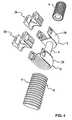
- Fig. 2shows first screws 1 with first head parts 3 and second screws 8 with second head parts 7.
- the first head parts 3are each formed from a U-shaped bracket 10, the inside of which are provided with ribs 11 and grooves 12.
- the elastic portion 4is also provided with circumferential ribs 13 and grooves 14. The elastic portion 4 is inserted in each case in the U-shaped bracket 10, wherein the ribs 11 and grooves 12 of the U-shaped bracket 10 each engage positively in the ribs 13 and grooves 14 of the elastic portion 4.
- the respective U-shaped bracket 10is then closed with a closure piece 15, wherein the closure pieces 15 are also provided on the elastic portion 4 facing region and on the sides with ribs 16 and grooves 17, so that these closure pieces 15 with the elastic Section 4 and the U-shaped bracket 10 form a positive connection.
- the closure piece 15can be held by a latching means 18 in the respective U-shaped bracket 10.
- Such screws with the elastic portion and the closure piecesare for example in the European Patent Application EP-A-1 527 742 described.
- the second head parts 7 of the second screws 8are likewise bow-shaped, so that a rigid section 6 can be inserted into these second head parts 7 of the second screw 8. Held this rigid portion 6 in a known manner via clamping screws 19 in the second head parts 7 of the second screw. 8
- the connecting means 5is fixed, with which the rigid portion 6 and the elastic portion 4 can be connected together.
- This rigid portion 6 and the elastic portion 4could also be assembled into a preassembled connecting element 9 and inserted and fixed in this preassembled state in the head parts 3 and 7 of the already screwed into the vertebrae screws 1 and 8.
- a U-shaped bracket 20is formed for this purpose.
- This U-shaped The bracketis provided with two legs 21 and 22.
- ribs 24 and grooves 25are mounted in the base 23 of this U-shaped bracket 20 and along the inside of the legs 21 and 22 .
- an end portion of the elastic portion 4can then be inserted, the ribs 24 and grooves 25 of the U-shaped bracket 20 then engage in the corresponding ribs 13 and grooves 14 of the elastic portion 4, one thus receives a positive connection, wherein the elastic portion 4 and the rigid portion 6 are aligned coaxially in the connected state.
- the U-shaped bracket 20can be closed by a closure piece 26, in this case the U-shaped bracket 20 is the same design as the U-shaped bracket 10 of the first screw 1, as in Fig. 2 it can be seen, the closure piece 26 thus corresponds to the closure piece 15 (also Fig. 2 ).
- the closure piece 26also has ribs and grooves on the region 27 facing the elastic portion, and corresponding ribs and grooves are also provided on the sides 28 and 29 of the closure piece 26.
- the closure member 26is positively connected in the inserted state in the U-shaped bracket 20 via the grooved sides 28 and 29 with the U-shaped bracket 20, a positive connection is also formed in the area 27, with the elastic portion 4.
- the closure piece 26is held by latching means 30 in the U-shaped bracket 20.
- the rigid portion 6 and the attached U-shaped bracket 20are formed of a metallic alloy, in particular a titanium alloy.
- the elastic portionconsists of a biocompatible plastic based on polyurethane, which this is the desired flexibility intrinsically, and the closure piece 26 is formed of the same material, whereby the latching means 30 carrying areas are elastically deformable for latching in the U-shaped bracket 20 and the latching means 30 can engage in the corresponding recesses 31 of the U-shaped bracket 20.
- Fig. 4shows a rigid portion 6, at its two end regions in each case a connecting device 5 is attached, as to Fig. 3 has been described.
- an elastic portion 4can be inserted into the U-shaped bracket 20 and held with the closure piece 26. So one can compare with the one in Fig. 3 9 shown differently formed connecting element 9 are obtained, the rigid portion 6 is held by second screws 8, while the elastic portions 4 by first screws 1 (Fig. Fig. 2 ) can be held.
- two vertebral bodiescould be rigidly stabilized via the rigid portion 6 and the corresponding second screws 8, the adjacent vertebral bodies, in which the first screws 1 are used, can be elastically stabilized.
- Fig. 5a and 5bshow a connecting device 5, which is fastened to the second head part 7 of a second screw 8.
- the connecting device 5is constructed in an identical manner as they are Fig. 3 has been described, with the exception that the U-shaped bracket 20 is not attached to the rigid portion 6, but at the second head portion 7 of the second screw 8.
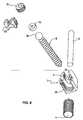
- Fig. 6shows in an application example, three second screws 8 with second head parts 7.
- a rigid portion 6is inserted, which is held in the second head parts 7 by the corresponding clamping screws 19.
- a short rigid section 6is also used, in this Fig. 6 is not visible and is held by the clamping screw 19.
- the two rigid sections 6are each provided at the ends facing each other with a connecting device 5, as this too Fig. 3 are described.
- the two lower illustrated second screws 8are rigidly connected to each other via the rigid portion 6 and would fix the corresponding vertebral bodies.
- the two upper illustrated second screws 8are connected to each other via an elastic portion 4, the corresponding vertebrae would be elastically stabilized.
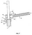
- the two Fig. 7 and 8thshow a second screw 8 with a second head part 7, to which head part 7 a U-shaped bracket 20 of a connecting device 5 is attached.
- the screw 8is separated from the head part 7.
- the head part 7has a receiving region 32, which has the shape of a spherical cap 33.
- the second screw 8is equipped with a ball head 34.
- the second screw 8can now be inserted into the second head part 7 so that the ball head 34 of the second screw 8 comes to lie in the spherical cap 33 of the second head part. On the ball head 34, an insert 35 is then inserted.
- the rigid portion 6can be inserted into the second head portion 7 of the second screw 8, via the clamping screw 19 then this rigid portion 6 is pressed against the insert 35, which pressure is passed to the ball head 34 of the second screw 8 and this ball head 34th then fixed in the spherical cap 33.
- the second head part 7 and thus the rigid portion 6can be adjusted with respect to the second screw 8 and then fixed.
- the U-shaped bracket 20can then, as has already been described previously, insert the elastic portion 4 and fix on the closure piece 26.
Landscapes
- Health & Medical Sciences (AREA)
- Orthopedic Medicine & Surgery (AREA)
- Life Sciences & Earth Sciences (AREA)
- Neurology (AREA)
- Surgery (AREA)
- Heart & Thoracic Surgery (AREA)
- Engineering & Computer Science (AREA)
- Biomedical Technology (AREA)
- Nuclear Medicine, Radiotherapy & Molecular Imaging (AREA)
- Medical Informatics (AREA)
- Molecular Biology (AREA)
- Animal Behavior & Ethology (AREA)
- General Health & Medical Sciences (AREA)
- Public Health (AREA)
- Veterinary Medicine (AREA)
- Prostheses (AREA)
- Surgical Instruments (AREA)
Description
Translated fromGermanDie vorliegende Erfindung bezieht sich auf ein Wirbelsäulenimplantat, umfassend ein Verbindungselement und mehrere Knochenschrauben die in die Wirbelkörper der Wirbelsäule einschraubbar sind und die mit je einem Kopfteil für die Aufnahme des Verbindungselementes ausgestattet sind mit welchen zwischen Knochenschrauben und Verbindungselement eine feste Verbindung erreichbar ist, und das Verbindungselement aus starren Abschnitten und elastischen Abschnitten zusammensetzbar ist und die starren Abschnitte über Verbindungseinrichtungen mit den elastischen Abschnitten verbindbar sind.The present invention relates to a spinal implant, comprising a connecting element and a plurality of bone screws which are screwed into the vertebral bodies of the spine and which are each equipped with a head portion for receiving the connecting element with which between bone screws and connecting element a firm connection can be reached, and Connecting element of rigid sections and elastic sections is composable and the rigid sections are connected via connecting means with the elastic portions.
Aus dem Stand der Technik sind derartige Wirbelsäulenimplantate in vielfältiger Weise bekannt. Man unterscheidet hierbei zwischen zwei Systemen, nämlich einem aus einem starren Verbindungselement bestehenden Stabilisierungssystemen, welche eine Versteifung der betroffenen Wirbelkörper zum Ziele haben, und elastischen Systemen, mit welchen eine stützende Stabilisierung der Wirbelkörper erreicht wird, wobei eine gewisse Beweglichkeit zwischen den einzelnen Wirbelkörpern erwünscht und zugelassen wird.Such spine implants are known in many ways from the prior art. A distinction is made here between two systems, namely one consisting of a rigid connecting element stabilization systems, which have a stiffening of the vertebral bodies concerned, and elastic systems, with which a supporting stabilization of the vertebral body is achieved, with a certain mobility between the individual vertebrae desired and is allowed.
Starre Stabilisierungssystem, die in vielfältiger Weise bekannt sind, haben, wie bereits erwähnt worden ist, das Ziel, dass die problematischen Wirbelkörper eine Versteifung erfahren, so dass ein knöchernes Verwachsen der betroffenen Wirbelkörper erreicht wird. Um eine optimale Stabilisierung erreichen zu können, müssen somit neben den problematischen Wirbelkörpern auch benachbarte gesunde Wirbelkörper mit einbezogen werden, was zur Folge haben kann, dass die Versteifung in einem zu grossen Bereich erfolgt. Zudem ist oft festgestellt worden, dass beim Übergang von stabilisierten zu nicht mehr stabilisierten Wirbelkörpern die Belastung der Wirbelsäule zu gross wird, so dass an dieser Übergangsstelle infolge der zu grossen Belastung der benachbarte Wirbelkörper Schaden nehmen kann.Rigid stabilization system, which are known in many ways, have, as already mentioned, the goal that the problematic vertebral bodies undergo a stiffening, so that a bony coalescence of the vertebrae concerned is achieved. In order to achieve optimal stabilization, adjacent to the problematic vertebrae also adjacent healthy vertebral bodies must be included, which can have the consequence that the stiffening takes place in a too large area. In addition, it has often been found that the transition from stabilized to unstable vertebrae, the burden of the spine is too large, so that at this transition point can take damage due to the excessive load of the adjacent vertebral body.
Wie ebenfalls bereits erwähnt worden ist, werden durch die bekannten elastischen Systeme die Wirbel unterstützend stabilisiert, wobei aber eine gewisse Beweglichkeit zwischen den Wirbelkörpern erwünscht und ermöglicht wird. Dieses System hat aber den Nachteil, dass stark in Mitleidenschaft gezogene Wirbelkörper, bei welchen eine Versteifung erwünscht wäre, mit diesem elastischen System nicht erreicht werden kann, ein knöchernes Verwachsen der betroffenen Wirbelkörper kann nicht erreicht werden.As has already been mentioned, are stabilized by the known elastic systems supporting the vertebra, but a certain mobility between the vertebral bodies desirable and possible becomes. However, this system has the disadvantage that severely affected vertebral bodies in which a stiffening would be desirable, can not be achieved with this elastic system, a bony coalescence of the vertebral bodies affected can not be achieved.
Aus der
Die Aufgabe der vorliegenden Erfindung besteht nun darin, ein Wirbelsäulenimplantat zu schaffen, mit welchem es möglich ist, bereichsweise eine starre Stabilisierung der Wirbelkörper zu erreichen, während im angrenzenden Bereich die Wirbelkörper durch ein elastisches System gestützt und stabilisiert werden, ohne dass eine Versteifung erfolgt, und welches optimal und einfach ermöglicht, die starren und die elastischen Elemente miteinander zu verbinden.The object of the present invention is now to provide a spinal implant, with which it is possible to achieve in regions a rigid stabilization of the vertebral bodies, while in the adjacent area, the vertebral bodies are supported and stabilized by an elastic system, without stiffening occurs, and which optimally and easily allows to connect the rigid and the elastic elements together.
Erfindungsgemäss erfolgt die Lösung dieser Aufgabe dadurch, dass die elastischen Abschnitte aus einem biokompatiblen Kunststoff gebildet sind und die Oberfläche mit umlaufenden Rippen und Rillen versehen sind und dass die Verbindungseinrichtungen aus einem aus starrem Material bestehenden U-förmigen Bügel gebildet sind, welche im Grund des Bügels und entlang der Innenseite der Schenkel den Rippen und Rillen der elastischen Abschnitte entsprechende Rillen und Rippen aufweisen.According to the invention, the solution of this object is achieved in that the elastic portions are formed of a biocompatible plastic and the surface are provided with circumferential ribs and grooves and that the connecting means are formed of a rigid material consisting of U-shaped bracket, which in the bottom of the bracket and along the inside of the legs have grooves and ribs corresponding to the ribs and grooves of the elastic portions.
Mit dieser Ausgestaltung der Erfindung wird ein modulares System geschaffen, bei welchem die Möglichkeit besteht, einander benachbarte Wirbelkörper starr zu stabilisieren, während weitere benachbarte Wirbelkörper elastisch gestützt und stabilisiert werden, wodurch eine eingeschränkte Bewegungsmöglichkeit zugelassen wird. Dadurch hat man verschiedenste Möglichkeiten, die Wirbelsäule bereichsweise elastisch oder starr zu stabilisieren, ohne dass der Eingriff am Patienten aufwendiger würde. Somit kann beispielsweise erreicht werden, dass die Übergangsphase von starr stabilisierten Wirbelkörpern zu den nicht mehr zu stabilisierenden Wirbelkörpern über einen elastisch stabilisierten Bereich schonender zu gestaltet werden kann, im Übergangsbereich vom starr stabilisierten Wirbelkörper zum nicht mehr stabilisierten Wirbelkörper kann somit mindestens eine Teilentlastung der betroffenen Wirbelkörper erreicht werden. Mit diesem modularen Wirbelsäulenimplantat ergeben sich somit an jeden Einzelfall optimal angepasste Lösungen, die einfach zu handhaben sind.With this embodiment of the invention, a modular system is provided in which there is the possibility of rigidly stabilizing adjacent vertebral bodies, while further adjacent vertebral bodies are elastically supported and stabilized, whereby a limited possibility of movement is permitted. As a result, one has a variety of ways to stabilize the spine partially elastic or rigid, without the intervention on the patient would be more expensive. Thus, for example, it can be achieved that the transition phase of rigidly stabilized vertebral bodies can be made more gentle to the no longer stabilized vertebral bodies over an elastically stabilized area, in the transition region from the rigidly stabilized vertebral body to the unstoppable vertebral body thus at least a partial relief of the vertebral bodies affected can be achieved. With this modular spinal column implant optimally adapted solutions result, which are easy to handle.
Indem die Verbindungseinrichtungen aus einem aus starren Material bestehenden U-förmigen Bügel gebildet sind, welche im Grund des Bügels und entlang der Innenseite der Schenkel den Rippen und Rillen der elastischen Abschnitte entsprechende Rillen und Rippen aufweisen, erhält man durch das Zusammenwirken der Rippen und Rillen in der Verbindungseinrichtung des elastischen Abschnitts und des U-förmigen Bügels eine feste, formschlüssige Verbindung, eine Pressung des elastischen Abschnitts, die bei einer Klemmverbindung erforderlich wäre und die zu einem Fliessverhalten des elastischen Abschnitts führen könnte, kann somit vermieden werden.By the connecting means are formed of a rigid material consisting of U-shaped bracket having in the base of the bracket and along the inside of the legs of the ribs and grooves of the elastic portions corresponding grooves and ribs, obtained by the interaction of the ribs and grooves in The connection means of the elastic portion and the U-shaped bracket a solid, positive connection, a pressing of the elastic portion, which would be required in a clamping connection and could lead to a flow behavior of the elastic portion can thus be avoided.
Eine vorteilhafte Ausgestaltung der Erfindung besteht darin, dass die Verbindungseinrichtungen so ausgestaltet sind, dass die jeweils miteinander verbundenen starren Abschnitte und die elastischen Abschnitte im wesentlichen koaxial ausgerichtet sind. Dies ergibt grosse Vorteile und Vereinfachungen beim Einsetzen von derartigen aus starren und elastischen Abschnitten zusammengesetzten Implantaten.An advantageous embodiment of the invention is that the connecting means are designed so that each interconnected rigid portions and the elastic portions are aligned substantially coaxially. This results in great advantages and simplifications in the insertion of such from rigid and elastic sections assembled implants.
In vorteilhafter Weise sind die starren Abschnitte aus einer metallischen Legierung, insbesondere einer Titanlegierung gebildet, was eine optimale Verträglichkeit bei den mit derartigen Implantaten versorgten Patienten bewirkt.Advantageously, the rigid sections are formed of a metallic alloy, in particular a titanium alloy, which ensures optimum compatibility with the patients treated with such implants.
In vorteilhafter Weise sind die elastischen Abschnitte aus einem biokompatiblen Kunststoff auf Basis von Polyurethan gebildet. Auch dadurch erreicht man eine optimale Verträglichkeit.Advantageously, the elastic portions are formed of a biocompatible plastic based on polyurethane. This also achieves optimal compatibility.
In vorteilhafter Weise ist der U-förmige Bügel mit dem eingesetzten elastischen Abschnitt mit einem Verschlussstück verschliessbar, welches zwischen die Bügel einsetzbar und über Einklinkmittel gehalten ist. Dadurch erhält man einen sehr einfachen Vorgang zum Einsetzen und Festhalten des elastischen Abschnitts im U-förmigen Bügel, was sich auf die Dauer des Eingriffs positiv auswirken kann.Advantageously, the U-shaped bracket is closed with the inserted elastic portion with a closure piece which is inserted between the bracket and held over Einklinkmittel. This gives a very simple operation for inserting and holding the elastic portion in the U-shaped bracket, which can have a positive effect on the duration of the procedure.
Eine weitere vorteilhafte Ausgestaltung der Erfindung besteht darin, dass das Verschlussstück im in den U-förmigen Bügel eingesetzten Zustand auf der dem Abschnitt zugewandten Seite den Rippen und Rillen des elastischen Abschnitts entsprechende Rippen und Rillen aufweist. Dadurch trägt auch das Verschlussstück zur formschlüssigen Verbindung zwischen dem elastischen Abschnitt und dem U-förmigen Bügel in optimaler Weise bei.A further advantageous embodiment of the invention is that the closure piece in the inserted state in the U-shaped bracket has on the side facing the portion of the ribs and grooves of the elastic portion corresponding ribs and grooves. As a result, the closure piece contributes to the positive connection between the elastic portion and the U-shaped bracket in an optimal manner.
In vorteilhafter Weise sind die Verbindungseinrichtungen jeweils an einem Ende eines starren Abschnitts oder am Kopfteil einer Schraube befestigt. Daraus ergibt sich eine optimale Anordnung dieser Verbindungseinrichtungen, das Verbinden der verschiedenen Abschnitte miteinander kann in optimaler Weise erfolgen.Advantageously, the connecting means are each attached to one end of a rigid portion or to the head portion of a screw. This results in an optimal arrangement of these connecting devices, the connection of the different sections together can be done in an optimal way.
Eine weitere vorteilhafte Ausgestaltung der Erfindung besteht darin, dass die Kopfteile der Schrauben von den Schrauben getrennt sind und einen Aufnahmebereich für die Aufnahme einer Schraube aufweisen, welche Schraube mit dem Kopfteil der Schraube über eine Klemmschraube, mit welcher der starre Abschnitt im Kopfteil der Schraube fixierbar ist, befestigbar ist. Dadurch können zuerst die Schrauben in die Wirbelkörper eingesetzt werden, der Kopfteil, in welchem die Abschnitte gehalten werden können, kann nachträglich bezüglich der Schraube und dem Verbindungselement ausgerichtet werden.A further advantageous embodiment of the invention is that the head parts of the screws are separated from the screws and have a receiving area for receiving a screw, which screw with the head part of the screw via a clamping screw, with which the rigid portion in the head part of the screw can be fixed is, is fastened. As a result, first the screws can be inserted into the vertebral body, the head part, in which the sections can be held, can be subsequently aligned with respect to the screw and the connecting element.
In vorteilhafter Weise weist der Aufnahmebereich des Kopfteils der Schraube für die Aufnahme einer Schraube die Form einer Kugelkalotte auf, und ist der obere Teil der Schraube als Kugelkopf ausgebildet. Dadurch lässt sich der Kopfteil bezüglich der Schraube optimal ausrichten und an die darin aufzunehmenden Abschnitte anpassen.Advantageously, the receiving portion of the head portion of the screw for receiving a screw in the form of a spherical cap, and the upper part of the screw is formed as a ball head. As a result, the head part can be aligned optimally with respect to the screw and adapted to the sections to be accommodated therein.
Ausführungsformen der Erfindung werden nachfolgend anhand der beiliegenden Zeichnung beispielhaft näher erläutert.Embodiments of the invention are explained in more detail by way of example with reference to the accompanying drawings.
Es zeigt:
Fig. 1 in schematischer nicht massstäblicher Darstellung ein in die Wirbelsäule eingesetztes Wirbelsäulenimplantat mit einem Verbindungselement, das aus einem starren Abschnitt und aus einem elastischen Abschnitt zusammengesetzt ist;Fig. 2 in räumlicher Darstellung das Wirbelsäulenimplantat, wie es inFig. 1 dargestellt ist;Fig. 3 in räumlicher Darstellung die Ansicht einer Verbindungseinrichtung;Fig. 4 in räumlicher Darstellung die Ansicht von weiteren Verbindungseinrichtungen;Fig. 5a in räumlicher Darstellung eine Verbindungseinrichtung, die am Kopfteil für eine Schraube angebracht ist;Fig. 5b eine Schnittdarstellung der Verbindungseinrichtung gemässFig. 5a ;Fig. 6 eine weitere Anordnung einer Möglichkeit für ein Wirbelsäulenimplantat in räumlicher Darstellung;Fig. 7 eine Schnittdarstellung einer Schraube mit aufgesetztem Kopfteil, wobei am Kopfteil eine Verbindungseinrichtung angebracht ist; undFig. 8 in auseinandergezogener räumlicher Darstellung eine Schraube mit Kopfteil und an diesem Kopfteil angebrachter Verbindungseinrichtung.
Fig. 1 in a schematic not to scale representation of a spinal implant inserted into the spine with a connecting element, which is composed of a rigid portion and an elastic portion;Fig. 2 in spatial representation the spinal implant, as it is inFig. 1 is shown;Fig. 3 in a spatial representation, the view of a connection device;Fig. 4 in a spatial representation, the view of further connecting devices;Fig. 5a in a spatial representation, a connecting device which is attached to the head part for a screw;Fig. 5b a sectional view of the connecting device according toFig. 5a ;Fig. 6 a further arrangement of a possibility for a spinal implant in a spatial representation;Fig. 7 a sectional view of a screw with attached head part, wherein on the head part, a connecting device is mounted; andFig. 8 in exploded spatial representation of a screw with headboard and attached to this head part connecting device.
Wie aus
Die zweiten Kopfteile 7 der zweiten Schrauben 8 sind ebenfalls bügelförmig ausgebildet, so dass ein starrer Abschnitt 6 in diese zweiten Kopfteile 7 der zweiten Schraube 8 eingelegt werden kann. Gehalten wird dieser starre Abschnitt 6 in bekannter Weise über Klemmschrauben 19 in den zweiten Kopfteilen 7 der zweiten Schrauben 8.The
Am starren Abschnitt 6 ist die Verbindungseinrichtung 5 befestigt, mit welcher der starre Abschnitt 6 und der elastische Abschnitt 4 miteinander verbunden werden können.At the
Dieser starre Abschnitt 6 und der elastische Abschnitt 4 könnten auch zu einem vormontierten Verbindungselement 9 zusammengefügt werden und in diesem vormontierten Zustand in die Kopfteile 3 und 7 der bereits in die Wirbelkörper eingeschraubten Schrauben 1 und 8 eingesetzt und fixiert werden.This
In
Der U-förmige Bügel 20 kann durch ein Verschlussstück 26 verschlossen werden, hierbei ist der U-förmige Bügel 20 gleich ausgebildet wie der U-förmige Bügel 10 der ersten Schraube 1, wie dies in
Der starre Abschnitt 6 und der daran befestigte U-förmige Bügel 20 sind aus einer metallischen Legierung, insbesondere einer Titanlegierung, gebildet. Der elastische Abschnitt besteht aus einem biokompatiblen Kunststoff auf Basis von Polyurethan, wodurch diesem die gewünschte Flexibilität eigen ist, auch das Verschlussstück 26 ist aus dem selben Material gebildet, wodurch zum Einklinken im U-förmigen Bügel 20 die die Einklinkmittel 30 tragenden Bereiche elastisch verformbar sind und die Einklinkmittel 30 in den entsprechenden Ausnehmungen 31 des U-förmigen Bügels 20 einklinken können.The
Die
Es wäre auch denkbar, anstelle der beiden oberen dargestellten zweiten Kopfteile 7 solche zweite Kopfteile 7 zu verwenden, die mit Verbindungseinrichtungen 5 ausgestattet sind, wie sie in
Das in
Die beiden
Mit diesem erfindungsgemässen Wirbelsäulenimplantat ergeben sich praktisch beliebige Kombinationsmöglichkeiten, so dass ein Verbindungselement aufgebaut werden kann, welches in die entsprechenden Knochenschrauben eingelegt werden kann und welches die gewünschte Stabilisierung auf die einzelnen Wirbelsäulenbereiche ermöglicht.With this inventive spinal implant, virtually any combination possibilities arise, so that a connecting element can be constructed, which can be inserted into the corresponding bone screws and which allows the desired stabilization of the individual spine areas.
Claims (10)
- Vertebral column implant, comprising a connecting element (9) and a multiplicity of bone screws (1, 8), which are screwable into the vertebral bodies (2) of the vertebral column and are each provided with a head part (3, 7) for receiving the connecting element (9), with which head parts a firm connection is achievable between bone screws (1, 8) and connecting element (9), and the connecting element (9) is able to be put together from rigid sections (6) and elastic sections (4), and the rigid sections (6) are connectible to the elastic sections (4) via connecting devices (5),characterised in that the elastic sections (4) are made of a biocompatible synthetic material and the surfaces are provided with encircling ribs (13) and grooves (14), andin that the connecting devices (5) are composed of a U-shaped bow (20) made of a rigid material, in which bow an elastic section can be placed, which connecting devices have at the bottom (23) of the bow (20) and along the inner side of the legs (21, 22) grooves (25) and ribs (24) corresponding to the ribs (13) and grooves (14) of the elastic sections (4).
- Vertebral column implant according to claim 1,characterised in that the connecting devices (5) are designed such that the rigid sections (6), connected together in each case, and the elastic sections (4) are aligned substantially coaxially.
- Vertebral column implant according to claim 1 or 2,characterised in that the rigid sections (6) are made of a metal alloy, in particular a titanium alloy.
- Vertebral column implant according to one of the claims 1 to 3,characterised in that the elastic sections (4) are made of a biocompatible synthetic material, based on polyurethane.
- Vertebral column implant according to one of the claims 1 to 4,characterised in that the U-shaped bow (20) with the inserted elastic section (4) is lockable with a locking piece (26), which is insertable between the legs (21, 22) of the bow (20) and is held via engagement means (30).
- Vertebral column implant according to claim 5,characterised in that the locking piece (26) has, in the state of being inserted in the U-shaped bow (20), ribs and grooves on the side facing the elastic section (4), corresponding to the ribs (13) and grooves (14) of the elastic section (4).
- Vertebral column implant according to one of the claims 1 to 6,characterised in that the connecting devices (5) are each attached at an end of a rigid section (6).
- Vertebral column implant according to one of the claims 1 to 6,characterised in that the connecting devices (5) are each attached at the head part (7) of a screw (8).
- Vertebral column implant according to one of the claims 1 to 8,characterised in that the head parts (7) of the screws (8) are separate from the screws (8), and have a receiving region (32) for receiving a screw (8), which screw (8) with the head part (7) of the screw (8) is attachable via a clamping screw (19), with which the rigid section (6) is able to be fixed in the head part (7) of the screw (8).
- Vertebral column implant according to claim 9,characterised in that the receiving region (32) of the head part (7) of the screw (8) has the shape of a spherical recess (33) for receiving a screw (8), and the upper portion of the screw (8) is designed as a spherical head (34).
Priority Applications (6)
| Application Number | Priority Date | Filing Date | Title |
|---|---|---|---|
| DE502006004368TDE502006004368D1 (en) | 2006-02-03 | 2006-02-03 | spinal implant |
| ES06101271TES2330132T3 (en) | 2006-02-03 | 2006-02-03 | VERTEBRAL COLUMN IMPLANT. |
| EP06101271AEP1815812B1 (en) | 2006-02-03 | 2006-02-03 | Spinal implant |
| US11/976,138US8162986B2 (en) | 2006-02-03 | 2007-10-22 | Vertebral column implant |
| US13/433,516US20120184994A1 (en) | 2006-02-03 | 2012-03-29 | Vertebral column implant |
| US13/433,441US20120184996A1 (en) | 2006-02-03 | 2012-03-29 | Vertebral column implant |
Applications Claiming Priority (1)
| Application Number | Priority Date | Filing Date | Title |
|---|---|---|---|
| EP06101271AEP1815812B1 (en) | 2006-02-03 | 2006-02-03 | Spinal implant |
Publications (2)
| Publication Number | Publication Date |
|---|---|
| EP1815812A1 EP1815812A1 (en) | 2007-08-08 |
| EP1815812B1true EP1815812B1 (en) | 2009-07-29 |
Family
ID=36604238
Family Applications (1)
| Application Number | Title | Priority Date | Filing Date |
|---|---|---|---|
| EP06101271ANot-in-forceEP1815812B1 (en) | 2006-02-03 | 2006-02-03 | Spinal implant |
Country Status (4)
| Country | Link |
|---|---|
| US (3) | US8162986B2 (en) |
| EP (1) | EP1815812B1 (en) |
| DE (1) | DE502006004368D1 (en) |
| ES (1) | ES2330132T3 (en) |
Cited By (4)
| Publication number | Priority date | Publication date | Assignee | Title |
|---|---|---|---|---|
| US7641673B2 (en) | 2000-07-25 | 2010-01-05 | Zimmer Spine, S.A.S. | Flexible linking piece for stabilising the spine |
| US8012182B2 (en) | 2000-07-25 | 2011-09-06 | Zimmer Spine S.A.S. | Semi-rigid linking piece for stabilizing the spine |
| US9101406B2 (en) | 2007-10-11 | 2015-08-11 | Zimmer Spine | Bone fixing system and method of use |
| US9204903B2 (en) | 2007-10-23 | 2015-12-08 | Zimmer Spine S.A.S. | Bone fixation tensioning tool and method |
Families Citing this family (119)
| Publication number | Priority date | Publication date | Assignee | Title |
|---|---|---|---|---|
| US7833250B2 (en) | 2004-11-10 | 2010-11-16 | Jackson Roger P | Polyaxial bone screw with helically wound capture connection |
| US20160242816A9 (en) | 2001-05-09 | 2016-08-25 | Roger P. Jackson | Dynamic spinal stabilization assembly with elastic bumpers and locking limited travel closure mechanisms |
| US10258382B2 (en) | 2007-01-18 | 2019-04-16 | Roger P. Jackson | Rod-cord dynamic connection assemblies with slidable bone anchor attachment members along the cord |
| US8292926B2 (en) | 2005-09-30 | 2012-10-23 | Jackson Roger P | Dynamic stabilization connecting member with elastic core and outer sleeve |
| US8353932B2 (en) | 2005-09-30 | 2013-01-15 | Jackson Roger P | Polyaxial bone anchor assembly with one-piece closure, pressure insert and plastic elongate member |
| US7862587B2 (en) | 2004-02-27 | 2011-01-04 | Jackson Roger P | Dynamic stabilization assemblies, tool set and method |
| US10729469B2 (en) | 2006-01-09 | 2020-08-04 | Roger P. Jackson | Flexible spinal stabilization assembly with spacer having off-axis core member |
| FR2842724B1 (en) | 2002-07-23 | 2005-05-27 | Spine Next Sa | VERTEBRAL FASTENING SYSTEM |
| WO2006052796A2 (en) | 2004-11-10 | 2006-05-18 | Jackson Roger P | Helical guide and advancement flange with break-off extensions |
| US8876868B2 (en) | 2002-09-06 | 2014-11-04 | Roger P. Jackson | Helical guide and advancement flange with radially loaded lip |
| US6716214B1 (en) | 2003-06-18 | 2004-04-06 | Roger P. Jackson | Polyaxial bone screw with spline capture connection |
| US7621918B2 (en) | 2004-11-23 | 2009-11-24 | Jackson Roger P | Spinal fixation tool set and method |
| US7377923B2 (en) | 2003-05-22 | 2008-05-27 | Alphatec Spine, Inc. | Variable angle spinal screw assembly |
| US8092500B2 (en) | 2007-05-01 | 2012-01-10 | Jackson Roger P | Dynamic stabilization connecting member with floating core, compression spacer and over-mold |
| US8137386B2 (en) | 2003-08-28 | 2012-03-20 | Jackson Roger P | Polyaxial bone screw apparatus |
| US7776067B2 (en) | 2005-05-27 | 2010-08-17 | Jackson Roger P | Polyaxial bone screw with shank articulation pressure insert and method |
| US7967850B2 (en) | 2003-06-18 | 2011-06-28 | Jackson Roger P | Polyaxial bone anchor with helical capture connection, insert and dual locking assembly |
| US8398682B2 (en) | 2003-06-18 | 2013-03-19 | Roger P. Jackson | Polyaxial bone screw assembly |
| US8926670B2 (en) | 2003-06-18 | 2015-01-06 | Roger P. Jackson | Polyaxial bone screw assembly |
| US7766915B2 (en) | 2004-02-27 | 2010-08-03 | Jackson Roger P | Dynamic fixation assemblies with inner core and outer coil-like member |
| US8377102B2 (en) | 2003-06-18 | 2013-02-19 | Roger P. Jackson | Polyaxial bone anchor with spline capture connection and lower pressure insert |
| US11419642B2 (en) | 2003-12-16 | 2022-08-23 | Medos International Sarl | Percutaneous access devices and bone anchor assemblies |
| US7179261B2 (en) | 2003-12-16 | 2007-02-20 | Depuy Spine, Inc. | Percutaneous access devices and bone anchor assemblies |
| US7527638B2 (en) | 2003-12-16 | 2009-05-05 | Depuy Spine, Inc. | Methods and devices for minimally invasive spinal fixation element placement |
| US7160300B2 (en) | 2004-02-27 | 2007-01-09 | Jackson Roger P | Orthopedic implant rod reduction tool set and method |
| JP2007525274A (en) | 2004-02-27 | 2007-09-06 | ロジャー・ピー・ジャクソン | Orthopedic implant rod reduction instrument set and method |
| US8152810B2 (en) | 2004-11-23 | 2012-04-10 | Jackson Roger P | Spinal fixation tool set and method |
| US11241261B2 (en) | 2005-09-30 | 2022-02-08 | Roger P Jackson | Apparatus and method for soft spinal stabilization using a tensionable cord and releasable end structure |
| US7901435B2 (en)* | 2004-05-28 | 2011-03-08 | Depuy Spine, Inc. | Anchoring systems and methods for correcting spinal deformities |
| US7651502B2 (en) | 2004-09-24 | 2010-01-26 | Jackson Roger P | Spinal fixation tool set and method for rod reduction and fastener insertion |
| US8926672B2 (en) | 2004-11-10 | 2015-01-06 | Roger P. Jackson | Splay control closure for open bone anchor |
| US9216041B2 (en) | 2009-06-15 | 2015-12-22 | Roger P. Jackson | Spinal connecting members with tensioned cords and rigid sleeves for engaging compression inserts |
| US9980753B2 (en) | 2009-06-15 | 2018-05-29 | Roger P Jackson | pivotal anchor with snap-in-place insert having rotation blocking extensions |
| WO2006057837A1 (en) | 2004-11-23 | 2006-06-01 | Jackson Roger P | Spinal fixation tool attachment structure |
| US8444681B2 (en) | 2009-06-15 | 2013-05-21 | Roger P. Jackson | Polyaxial bone anchor with pop-on shank, friction fit retainer and winged insert |
| US9168069B2 (en) | 2009-06-15 | 2015-10-27 | Roger P. Jackson | Polyaxial bone anchor with pop-on shank and winged insert with lower skirt for engaging a friction fit retainer |
| US8308782B2 (en) | 2004-11-23 | 2012-11-13 | Jackson Roger P | Bone anchors with longitudinal connecting member engaging inserts and closures for fixation and optional angulation |
| US7901437B2 (en)* | 2007-01-26 | 2011-03-08 | Jackson Roger P | Dynamic stabilization member with molded connection |
| US10076361B2 (en) | 2005-02-22 | 2018-09-18 | Roger P. Jackson | Polyaxial bone screw with spherical capture, compression and alignment and retention structures |
| FR2890850B1 (en) | 2005-09-20 | 2009-04-17 | Abbott Spine Sa | VERTEBRAL FASTENING SYSTEM |
| FR2890851B1 (en) | 2005-09-21 | 2008-06-20 | Abbott Spine Sa | ANCILLARY TO TENSION A FLEXIBLE LINK. |
| US8105368B2 (en) | 2005-09-30 | 2012-01-31 | Jackson Roger P | Dynamic stabilization connecting member with slitted core and outer sleeve |
| US8100946B2 (en) | 2005-11-21 | 2012-01-24 | Synthes Usa, Llc | Polyaxial bone anchors with increased angulation |
| US7806913B2 (en)* | 2006-08-16 | 2010-10-05 | Depuy Spine, Inc. | Modular multi-level spine stabilization system and method |
| CA2670988C (en) | 2006-12-08 | 2014-03-25 | Roger P. Jackson | Tool system for dynamic spinal implants |
| US8366745B2 (en) | 2007-05-01 | 2013-02-05 | Jackson Roger P | Dynamic stabilization assembly having pre-compressed spacers with differential displacements |
| US8475498B2 (en) | 2007-01-18 | 2013-07-02 | Roger P. Jackson | Dynamic stabilization connecting member with cord connection |
| US10792074B2 (en) | 2007-01-22 | 2020-10-06 | Roger P. Jackson | Pivotal bone anchor assemly with twist-in-place friction fit insert |
| US8012177B2 (en) | 2007-02-12 | 2011-09-06 | Jackson Roger P | Dynamic stabilization assembly with frusto-conical connection |
| US8979904B2 (en) | 2007-05-01 | 2015-03-17 | Roger P Jackson | Connecting member with tensioned cord, low profile rigid sleeve and spacer with torsion control |
| US10383660B2 (en) | 2007-05-01 | 2019-08-20 | Roger P. Jackson | Soft stabilization assemblies with pretensioned cords |
| CA2690038C (en) | 2007-05-31 | 2012-11-27 | Roger P. Jackson | Dynamic stabilization connecting member with pre-tensioned solid core |
| US20080312694A1 (en)* | 2007-06-15 | 2008-12-18 | Peterman Marc M | Dynamic stabilization rod for spinal implants and methods for manufacturing the same |
| US9439681B2 (en) | 2007-07-20 | 2016-09-13 | DePuy Synthes Products, Inc. | Polyaxial bone fixation element |
| US20090093819A1 (en)* | 2007-10-05 | 2009-04-09 | Abhijeet Joshi | Anisotropic spinal stabilization rod |
| US20090093843A1 (en)* | 2007-10-05 | 2009-04-09 | Lemoine Jeremy J | Dynamic spine stabilization system |
| EP2047810B1 (en)* | 2007-10-11 | 2011-09-28 | BIEDERMANN MOTECH GmbH | Modular rod system for spinal stabilization |
| EP2047812B1 (en)* | 2007-10-11 | 2011-12-14 | BIEDERMANN MOTECH GmbH | Bone anchoring device |
| US8911477B2 (en) | 2007-10-23 | 2014-12-16 | Roger P. Jackson | Dynamic stabilization member with end plate support and cable core extension |
| ATE536824T1 (en) | 2007-10-23 | 2011-12-15 | Zimmer Spine | FASTENING DEVICES AND STABILIZATION SYSTEMS WITH THESE FASTENING DEVICES |
| EP2074957B1 (en)* | 2007-12-31 | 2013-04-17 | Spinelab AG | Pedicle screw with a locking device for attaching a rod to stabilise the spine |
| KR100837108B1 (en)* | 2008-01-11 | 2008-06-11 | 최길운 | Flexible Rod for Spinal Fixation |
| EP2082697B1 (en)* | 2008-01-28 | 2011-02-09 | Spinelab AG | Pedicular screw with a locking device |
| US20090248077A1 (en)* | 2008-03-31 | 2009-10-01 | Derrick William Johns | Hybrid dynamic stabilization |
| ATE515239T1 (en) | 2008-04-24 | 2011-07-15 | Zimmer Spine | SYSTEM FOR STABILIZING AT LEAST ONE SECTION OF THE SPINE |
| EP2441404B1 (en)* | 2008-04-28 | 2013-07-31 | Biedermann Technologies GmbH & Co. KG | Rod-shaped implant, in particular for spinal stabilization, and method for producing the same |
| US8617215B2 (en)* | 2008-05-14 | 2013-12-31 | Warsaw Orthopedic, Inc. | Connecting element and system for flexible spinal stabilization |
| EP2303163B1 (en) | 2008-05-20 | 2011-11-23 | Zimmer Spine | System for stabilizing at least three vertebrae |
| US8246654B2 (en)* | 2008-06-16 | 2012-08-21 | U.S. Spine, Inc. | Transfacet fixation assembly and related surgical methods |
| US20100004693A1 (en)* | 2008-07-01 | 2010-01-07 | Peter Thomas Miller | Cam locking spine stabilization system and method |
| US8118837B2 (en)* | 2008-07-03 | 2012-02-21 | Zimmer Spine, Inc. | Tapered-lock spinal rod connectors and methods for use |
| US8167914B1 (en) | 2008-07-16 | 2012-05-01 | Zimmer Spine, Inc. | Locking insert for spine stabilization and method of use |
| US8197512B1 (en) | 2008-07-16 | 2012-06-12 | Zimmer Spine, Inc. | System and method for spine stabilization using resilient inserts |
| AU2010260521C1 (en) | 2008-08-01 | 2013-08-01 | Roger P. Jackson | Longitudinal connecting member with sleeved tensioned cords |
| US8287571B2 (en)* | 2008-08-12 | 2012-10-16 | Blackstone Medical, Inc. | Apparatus for stabilizing vertebral bodies |
| JP5815407B2 (en) | 2008-09-12 | 2015-11-17 | ジンテス ゲゼルシャフト ミット ベシュレンクテル ハフツング | Spinal stabilization and guided fixation system |
| KR20110081208A (en) | 2008-09-29 | 2011-07-13 | 신세스 게엠바하 | Multi-Axis Bottom-Loading Screw and Rod Assemblies |
| CA2742399A1 (en) | 2008-11-03 | 2010-06-03 | Dustin M. Harvey | Uni-planar bone fixation assembly |
| US20100114165A1 (en)* | 2008-11-04 | 2010-05-06 | Abbott Spine, Inc. | Posterior dynamic stabilization system with pivoting collars |
| US20100160968A1 (en)* | 2008-12-19 | 2010-06-24 | Abbott Spine Inc. | Systems and methods for pedicle screw-based spine stabilization using flexible bands |
| US8882803B2 (en)* | 2009-04-01 | 2014-11-11 | Globus Medical, Inc. | Orthopedic clamp and extension rod |
| KR20120013312A (en) | 2009-04-15 | 2012-02-14 | 신세스 게엠바하 | Orthodontic Connectors for Spinal Structures |
| CN103826560A (en) | 2009-06-15 | 2014-05-28 | 罗杰.P.杰克逊 | Polyaxial Bone Anchor with Socket Stem and Winged Inserts with Friction Fit Compression Collars |
| US9668771B2 (en) | 2009-06-15 | 2017-06-06 | Roger P Jackson | Soft stabilization assemblies with off-set connector |
| US11229457B2 (en) | 2009-06-15 | 2022-01-25 | Roger P. Jackson | Pivotal bone anchor assembly with insert tool deployment |
| US8998959B2 (en) | 2009-06-15 | 2015-04-07 | Roger P Jackson | Polyaxial bone anchors with pop-on shank, fully constrained friction fit retainer and lock and release insert |
| CA2764841A1 (en)* | 2009-06-17 | 2010-12-23 | Synthes Usa, Llc | Revision connector for spinal constructs |
| EP2279705A1 (en)* | 2009-07-28 | 2011-02-02 | Spinelab AG | Spinal implant |
| US8657856B2 (en)* | 2009-08-28 | 2014-02-25 | Pioneer Surgical Technology, Inc. | Size transition spinal rod |
| US20110066187A1 (en)* | 2009-09-11 | 2011-03-17 | Zimmer Spine, Inc. | Spinal stabilization system |
| EP2485654B1 (en) | 2009-10-05 | 2021-05-05 | Jackson P. Roger | Polyaxial bone anchor with non-pivotable retainer and pop-on shank, some with friction fit |
| US20120041490A1 (en)* | 2009-11-18 | 2012-02-16 | Synthes Usa, Llc | Variable offset spine fixation system and method |
| US8740945B2 (en) | 2010-04-07 | 2014-06-03 | Zimmer Spine, Inc. | Dynamic stabilization system using polyaxial screws |
| US12383311B2 (en) | 2010-05-14 | 2025-08-12 | Roger P. Jackson | Pivotal bone anchor assembly and method for use thereof |
| CH703411A2 (en) | 2010-07-12 | 2012-01-13 | Spinelab Ag | Spinal implant with pedicle screws and the corresponding pedicle screw. |
| DK2608728T3 (en) | 2010-08-26 | 2018-01-22 | Spinesave Ag | Vertebral column implant kit for dynamic stabilization of the vertebral column |
| AU2011299558A1 (en) | 2010-09-08 | 2013-05-02 | Roger P. Jackson | Dynamic stabilization members with elastic and inelastic sections |
| EP2436325B1 (en)* | 2010-10-01 | 2013-11-27 | Spinelab AG | Spinal implant for stabilising and reinforcing spinal bodies |
| AU2011324058A1 (en) | 2010-11-02 | 2013-06-20 | Roger P. Jackson | Polyaxial bone anchor with pop-on shank and pivotable retainer |
| US20120116458A1 (en)* | 2010-11-08 | 2012-05-10 | Warsaw Orthopedic, Inc. | Modular pivotable screw assembly and method |
| JP5865479B2 (en) | 2011-03-24 | 2016-02-17 | ロジャー・ピー・ジャクソン | Multiaxial bone anchor with compound joint and pop-mounted shank |
| EP2505154A1 (en)* | 2011-03-31 | 2012-10-03 | Spinelab AG | Spinal implant |
| EP2505155A1 (en)* | 2011-03-31 | 2012-10-03 | Spinelab AG | Spinal implant for stabilising and reinforcing spinal bodies of a spine |
| US8911479B2 (en) | 2012-01-10 | 2014-12-16 | Roger P. Jackson | Multi-start closures for open implants |
| US8911478B2 (en) | 2012-11-21 | 2014-12-16 | Roger P. Jackson | Splay control closure for open bone anchor |
| US10058354B2 (en) | 2013-01-28 | 2018-08-28 | Roger P. Jackson | Pivotal bone anchor assembly with frictional shank head seating surfaces |
| US8852239B2 (en) | 2013-02-15 | 2014-10-07 | Roger P Jackson | Sagittal angle screw with integral shank and receiver |
| EP2774563A1 (en)* | 2013-03-08 | 2014-09-10 | Spinelab AG | Spinal implant for stabilising and reinforcing spinal bodies of a spine |
| US9566092B2 (en) | 2013-10-29 | 2017-02-14 | Roger P. Jackson | Cervical bone anchor with collet retainer and outer locking sleeve |
| US9717533B2 (en) | 2013-12-12 | 2017-08-01 | Roger P. Jackson | Bone anchor closure pivot-splay control flange form guide and advancement structure |
| US9451993B2 (en) | 2014-01-09 | 2016-09-27 | Roger P. Jackson | Bi-radial pop-on cervical bone anchor |
| US10064658B2 (en) | 2014-06-04 | 2018-09-04 | Roger P. Jackson | Polyaxial bone anchor with insert guides |
| US9597119B2 (en) | 2014-06-04 | 2017-03-21 | Roger P. Jackson | Polyaxial bone anchor with polymer sleeve |
| US10335205B2 (en)* | 2015-11-09 | 2019-07-02 | Globus Medical, Inc. | MIS cross-connector |
| WO2017107883A1 (en)* | 2015-12-23 | 2017-06-29 | 马向阳 | Screw-rod fixation device specially used for posterior atlantoaxial vertebrae |
| US11141229B2 (en) | 2016-06-03 | 2021-10-12 | Rubicon Spine Llc | Dynamic feedback end effector |
| US10595907B2 (en)* | 2017-02-16 | 2020-03-24 | Rubicon Spine Llc | Polyaxial pedicle screw |
| CN114099090A (en)* | 2020-09-01 | 2022-03-01 | 上海三友医疗器械股份有限公司 | Fusion cage structure |
| CN118750129B (en)* | 2024-07-12 | 2025-05-23 | 中国医学科学院北京协和医院 | A double-locking pedicle screw for fusion and non-fusion surgery |
Family Cites Families (42)
| Publication number | Priority date | Publication date | Assignee | Title |
|---|---|---|---|---|
| DE4243951C2 (en)* | 1992-12-23 | 1997-07-03 | Plus Endoprothetik Ag | Device for stiffening a spinal column section consisting of at least two vertebrae |
| FR2763832B1 (en)* | 1997-05-29 | 1999-10-01 | Materiel Orthopedique En Abreg | VERTEBRAL ROD FOR INSTRUMENTATION OF RACHIDIAN OSTEOSYNTHESIS, AND OSTEOSYNTHESIS INSTRUMENTATION COMPRISING SUCH ROD |
| FR2827498B1 (en)* | 2001-07-18 | 2004-05-14 | Frederic Fortin | FLEXIBLE VERTEBRAL CONNECTION DEVICE CONSISTING OF PALLIANT ELEMENTS OF THE RACHIS |
| IL162363A0 (en)* | 2001-12-07 | 2005-11-20 | Mathys Medizinaltechnik Ag | Damping element |
| EP1364622B1 (en)* | 2002-05-21 | 2005-07-20 | Spinelab GmbH | Elastical system for stabilising the spine |
| FR2844180B1 (en)* | 2002-09-11 | 2005-08-05 | Spinevision | CONNECTING ELEMENT FOR THE DYNAMIC STABILIZATION OF A SPINAL FIXING SYSTEM AND SPINAL FASTENING SYSTEM COMPRISING SUCH A MEMBER |
| US7473267B2 (en)* | 2003-04-25 | 2009-01-06 | Warsaw Orthopedic, Inc. | System and method for minimally invasive posterior fixation |
| JP5078355B2 (en)* | 2003-05-23 | 2012-11-21 | グローバス メディカル インコーポレイティッド | Spine stabilization system |
| US20050203513A1 (en)* | 2003-09-24 | 2005-09-15 | Tae-Ahn Jahng | Spinal stabilization device |
| JP2007508085A (en)* | 2003-10-17 | 2007-04-05 | ヴィーダーマン モテッヒ ゲーエムベーハー | Flexible implant |
| DE10348329B3 (en)* | 2003-10-17 | 2005-02-17 | Biedermann Motech Gmbh | Rod-shaped element used in spinal column and accident surgery for connecting two bone-anchoring elements comprises a rigid section and an elastic section that are made in one piece |
| EP1527742B1 (en) | 2003-10-31 | 2006-07-26 | Spinelab AG | Locking cap for pedicle screws for fixing of elastic rods |
| DE102004011685A1 (en)* | 2004-03-09 | 2005-09-29 | Biedermann Motech Gmbh | Spine supporting element, comprising spiraled grooves at outer surface and three plain areas |
| US7744634B2 (en)* | 2004-06-15 | 2010-06-29 | Warsaw Orthopedic, Inc. | Spinal rod system |
| US7935134B2 (en)* | 2004-10-20 | 2011-05-03 | Exactech, Inc. | Systems and methods for stabilization of bone structures |
| EP1719468A1 (en)* | 2004-12-17 | 2006-11-08 | Zimmer GmbH | Intervertebral stabilization system |
| US7901437B2 (en)* | 2007-01-26 | 2011-03-08 | Jackson Roger P | Dynamic stabilization member with molded connection |
| US7556639B2 (en)* | 2005-03-03 | 2009-07-07 | Accelerated Innovation, Llc | Methods and apparatus for vertebral stabilization using sleeved springs |
| US7993371B2 (en)* | 2005-04-29 | 2011-08-09 | Warsaw Orthopedic, Inc. | Spinal construct system |
| US7828825B2 (en)* | 2005-06-20 | 2010-11-09 | Warsaw Orthopedic, Inc. | Multi-level multi-functional spinal stabilization systems and methods |
| CH705709B1 (en)* | 2005-08-29 | 2013-05-15 | Bird Biedermann Ag | Spinal implant. |
| US8105368B2 (en)* | 2005-09-30 | 2012-01-31 | Jackson Roger P | Dynamic stabilization connecting member with slitted core and outer sleeve |
| US20070270821A1 (en)* | 2006-04-28 | 2007-11-22 | Sdgi Holdings, Inc. | Vertebral stabilizer |
| US7806913B2 (en)* | 2006-08-16 | 2010-10-05 | Depuy Spine, Inc. | Modular multi-level spine stabilization system and method |
| ES2336815T5 (en)* | 2006-09-15 | 2013-05-16 | Biedermann Technologies Gmbh & Co. Kg | Bone anchoring device |
| US20080147122A1 (en)* | 2006-10-12 | 2008-06-19 | Jackson Roger P | Dynamic stabilization connecting member with molded inner segment and surrounding external elastomer |
| US20080177316A1 (en)* | 2006-11-30 | 2008-07-24 | Bergeron Brian J | Apparatus and methods for spinal implant |
| US7824430B2 (en)* | 2006-12-08 | 2010-11-02 | Warsaw Orthopedic, Inc. | Methods and devices for treating a multi-level spinal deformity |
| US8029544B2 (en)* | 2007-01-02 | 2011-10-04 | Zimmer Spine, Inc. | Spine stiffening device |
| US8475498B2 (en)* | 2007-01-18 | 2013-07-02 | Roger P. Jackson | Dynamic stabilization connecting member with cord connection |
| US8012177B2 (en)* | 2007-02-12 | 2011-09-06 | Jackson Roger P | Dynamic stabilization assembly with frusto-conical connection |
| US8097022B2 (en)* | 2007-02-20 | 2012-01-17 | Warsaw Orthopedic, Inc. | Flexible coupling members for spinal stabilization members |
| EP2301456B1 (en)* | 2007-02-23 | 2013-04-17 | Biedermann Technologies GmbH & Co. KG | Rod connector for stabilizing vertebrae |
| US8057516B2 (en)* | 2007-03-21 | 2011-11-15 | Zimmer Spine, Inc. | Spinal stabilization system with rigid and flexible elements |
| US8080038B2 (en)* | 2007-08-17 | 2011-12-20 | Jmea Corporation | Dynamic stabilization device for spine |
| EP2047810B1 (en)* | 2007-10-11 | 2011-09-28 | BIEDERMANN MOTECH GmbH | Modular rod system for spinal stabilization |
| US20100318130A1 (en)* | 2007-12-15 | 2010-12-16 | Parlato Brian D | Flexible rod assembly for spinal fixation |
| US8425564B2 (en)* | 2008-01-03 | 2013-04-23 | P. Douglas Kiester | Spine reconstruction rod extender |
| EP2153786B1 (en)* | 2008-08-12 | 2011-10-26 | BIEDERMANN MOTECH GmbH | Modular system for the stabilization of the spinal column |
| US20100217319A1 (en)* | 2009-02-24 | 2010-08-26 | Abbott Spine Inc. | System and method for spinal stabilization |
| US20110009906A1 (en)* | 2009-07-13 | 2011-01-13 | Zimmer Spine, Inc. | Vertebral stabilization transition connector |
| US8382803B2 (en)* | 2010-08-30 | 2013-02-26 | Zimmer Gmbh | Vertebral stabilization transition connector |
- 2006
- 2006-02-03EPEP06101271Apatent/EP1815812B1/ennot_activeNot-in-force
- 2006-02-03ESES06101271Tpatent/ES2330132T3/enactiveActive
- 2006-02-03DEDE502006004368Tpatent/DE502006004368D1/enactiveActive
- 2007
- 2007-10-22USUS11/976,138patent/US8162986B2/ennot_activeExpired - Fee Related
- 2012
- 2012-03-29USUS13/433,441patent/US20120184996A1/ennot_activeAbandoned
- 2012-03-29USUS13/433,516patent/US20120184994A1/ennot_activeAbandoned
Cited By (5)
| Publication number | Priority date | Publication date | Assignee | Title |
|---|---|---|---|---|
| US7641673B2 (en) | 2000-07-25 | 2010-01-05 | Zimmer Spine, S.A.S. | Flexible linking piece for stabilising the spine |
| US8012182B2 (en) | 2000-07-25 | 2011-09-06 | Zimmer Spine S.A.S. | Semi-rigid linking piece for stabilizing the spine |
| US9101406B2 (en) | 2007-10-11 | 2015-08-11 | Zimmer Spine | Bone fixing system and method of use |
| US9204903B2 (en) | 2007-10-23 | 2015-12-08 | Zimmer Spine S.A.S. | Bone fixation tensioning tool and method |
| US9204902B2 (en) | 2007-10-23 | 2015-12-08 | Zimmer Spine S.A.S | Bone fixation tensioning tool and method |
Also Published As
| Publication number | Publication date |
|---|---|
| US8162986B2 (en) | 2012-04-24 |
| US20120184994A1 (en) | 2012-07-19 |
| EP1815812A1 (en) | 2007-08-08 |
| ES2330132T3 (en) | 2009-12-04 |
| US20080058812A1 (en) | 2008-03-06 |
| US20120184996A1 (en) | 2012-07-19 |
| DE502006004368D1 (en) | 2009-09-10 |
Similar Documents
| Publication | Publication Date | Title |
|---|---|---|
| EP1815812B1 (en) | Spinal implant | |
| EP1667591B1 (en) | Device for elastically stabilising vertebral bodies | |
| DE69925374T2 (en) | SPINAL OSTEOSYNTHESIS SYSTEM WITH IMPROVED STABILITY | |
| DE3936702C2 (en) | Pedicle screw and correction and holding device with such a pedicle screw | |
| DE69810913T2 (en) | DEVICE FOR SPINE OSTEOSYTHESIS WITH STOVELY DISPOSED INTERVAL ANCHOR STICK | |
| DE69330178T2 (en) | Device for placing a spine | |
| EP1574173B1 (en) | Elastic rod-shaped element for use in spinal or accident surgery and stabilising device comprising such an element | |
| DE69010650T2 (en) | DEVICE FOR STRAIGHTING, FASTENING, PRESSING AND EXTENDING THE SPINE. | |
| DE3306657C2 (en) | Spine correction implant with a distraction rod | |
| DE69419407T2 (en) | UNIVERSAL STABILIZER FOR THE SPINE | |
| DE60037352T2 (en) | Apparatus for stabilizing the spine | |
| DE69719431T2 (en) | Vertebral cage set | |
| DE69818001T2 (en) | OSTEOSYNTHESIS SYSTEM FOR VERBELARTHRODESE | |
| EP1925264B1 (en) | Bone anchoring element | |
| EP2074957B1 (en) | Pedicle screw with a locking device for attaching a rod to stabilise the spine | |
| EP2226039B1 (en) | Implant for the thoracic and lumbar spine | |
| EP0328883B1 (en) | Supporting device for the human spinal column | |
| EP0776635A1 (en) | Anchoring element | |
| EP2279705A1 (en) | Spinal implant | |
| WO1995001132A1 (en) | Posterior vertebral column implant | |
| EP1121902A2 (en) | Pedicle screw | |
| DE10327358A1 (en) | Implant for correction and stabilization of the spine | |
| DE102004010844A1 (en) | Stabilizing device for the dynamic stabilization of vertebrae or bones and rod-shaped element for such a stabilization device | |
| DE102006024168A1 (en) | Placeholder for implantation to the human vertebrae has three tubular bodies having different lengths and diameters that are inserted and connected to each other by pins so that they project over the edges of the next larger tubular body | |
| EP2505154A1 (en) | Spinal implant |
Legal Events
| Date | Code | Title | Description |
|---|---|---|---|
| PUAI | Public reference made under article 153(3) epc to a published international application that has entered the european phase | Free format text:ORIGINAL CODE: 0009012 | |
| AK | Designated contracting states | Kind code of ref document:A1 Designated state(s):AT BE BG CH CY CZ DE DK EE ES FI FR GB GR HU IE IS IT LI LT LU LV MC NL PL PT RO SE SI SK TR | |
| AX | Request for extension of the european patent | Extension state:AL BA HR MK YU | |
| 17P | Request for examination filed | Effective date:20071215 | |
| AKX | Designation fees paid | Designated state(s):CH DE ES FR GB IT LI | |
| GRAP | Despatch of communication of intention to grant a patent | Free format text:ORIGINAL CODE: EPIDOSNIGR1 | |
| GRAS | Grant fee paid | Free format text:ORIGINAL CODE: EPIDOSNIGR3 | |
| GRAA | (expected) grant | Free format text:ORIGINAL CODE: 0009210 | |
| AK | Designated contracting states | Kind code of ref document:B1 Designated state(s):CH DE ES FR GB IT LI | |
| REG | Reference to a national code | Ref country code:GB Ref legal event code:FG4D Free format text:NOT ENGLISH | |
| REG | Reference to a national code | Ref country code:CH Ref legal event code:EP | |
| REF | Corresponds to: | Ref document number:502006004368 Country of ref document:DE Date of ref document:20090910 Kind code of ref document:P | |
| REG | Reference to a national code | Ref country code:CH Ref legal event code:NV Representative=s name:BOVARD AG PATENTANWAELTE | |
| REG | Reference to a national code | Ref country code:ES Ref legal event code:FG2A Ref document number:2330132 Country of ref document:ES Kind code of ref document:T3 | |
| PLBE | No opposition filed within time limit | Free format text:ORIGINAL CODE: 0009261 | |
| STAA | Information on the status of an ep patent application or granted ep patent | Free format text:STATUS: NO OPPOSITION FILED WITHIN TIME LIMIT | |
| 26N | No opposition filed | Effective date:20100503 | |
| REG | Reference to a national code | Ref country code:CH Ref legal event code:PFA Owner name:SPINELAB AG Free format text:SPINELAB AG#BAHNHOFSTRASSE 21#6304 ZUG (CH) -TRANSFER TO- SPINELAB AG#BAHNHOFSTRASSE 21#6304 ZUG (CH) | |
| PGFP | Annual fee paid to national office [announced via postgrant information from national office to epo] | Ref country code:DE Payment date:20140219 Year of fee payment:9 Ref country code:CH Payment date:20140206 Year of fee payment:9 | |
| PGFP | Annual fee paid to national office [announced via postgrant information from national office to epo] | Ref country code:FR Payment date:20140219 Year of fee payment:9 Ref country code:IT Payment date:20140225 Year of fee payment:9 Ref country code:ES Payment date:20140219 Year of fee payment:9 | |
| PGFP | Annual fee paid to national office [announced via postgrant information from national office to epo] | Ref country code:GB Payment date:20140218 Year of fee payment:9 | |
| REG | Reference to a national code | Ref country code:DE Ref legal event code:R119 Ref document number:502006004368 Country of ref document:DE | |
| REG | Reference to a national code | Ref country code:CH Ref legal event code:PL | |
| GBPC | Gb: european patent ceased through non-payment of renewal fee | Effective date:20150203 | |
| PG25 | Lapsed in a contracting state [announced via postgrant information from national office to epo] | Ref country code:CH Free format text:LAPSE BECAUSE OF NON-PAYMENT OF DUE FEES Effective date:20150228 Ref country code:LI Free format text:LAPSE BECAUSE OF NON-PAYMENT OF DUE FEES Effective date:20150228 | |
| REG | Reference to a national code | Ref country code:FR Ref legal event code:ST Effective date:20151030 | |
| PG25 | Lapsed in a contracting state [announced via postgrant information from national office to epo] | Ref country code:IT Free format text:LAPSE BECAUSE OF NON-PAYMENT OF DUE FEES Effective date:20150203 | |
| PG25 | Lapsed in a contracting state [announced via postgrant information from national office to epo] | Ref country code:GB Free format text:LAPSE BECAUSE OF NON-PAYMENT OF DUE FEES Effective date:20150203 Ref country code:DE Free format text:LAPSE BECAUSE OF NON-PAYMENT OF DUE FEES Effective date:20150901 | |
| PG25 | Lapsed in a contracting state [announced via postgrant information from national office to epo] | Ref country code:FR Free format text:LAPSE BECAUSE OF NON-PAYMENT OF DUE FEES Effective date:20150302 | |
| REG | Reference to a national code | Ref country code:ES Ref legal event code:FD2A Effective date:20160329 | |
| PG25 | Lapsed in a contracting state [announced via postgrant information from national office to epo] | Ref country code:ES Free format text:LAPSE BECAUSE OF NON-PAYMENT OF DUE FEES Effective date:20150204 |