EP1815337B1 - Storage system condition indicator and method - Google Patents
Storage system condition indicator and methodDownload PDFInfo
- Publication number
- EP1815337B1 EP1815337B1EP05822403.1AEP05822403AEP1815337B1EP 1815337 B1EP1815337 B1EP 1815337B1EP 05822403 AEP05822403 AEP 05822403AEP 1815337 B1EP1815337 B1EP 1815337B1
- Authority
- EP
- European Patent Office
- Prior art keywords
- storage
- condition
- indicating
- data
- storage system
- Prior art date
- Legal status (The legal status is an assumption and is not a legal conclusion. Google has not performed a legal analysis and makes no representation as to the accuracy of the status listed.)
- Not-in-force
Links
Images


Classifications
- G—PHYSICS
- G06—COMPUTING OR CALCULATING; COUNTING
- G06F—ELECTRIC DIGITAL DATA PROCESSING
- G06F11/00—Error detection; Error correction; Monitoring
- G06F11/07—Responding to the occurrence of a fault, e.g. fault tolerance
- G06F11/16—Error detection or correction of the data by redundancy in hardware
- G06F11/20—Error detection or correction of the data by redundancy in hardware using active fault-masking, e.g. by switching out faulty elements or by switching in spare elements
- G06F11/2053—Error detection or correction of the data by redundancy in hardware using active fault-masking, e.g. by switching out faulty elements or by switching in spare elements where persistent mass storage functionality or persistent mass storage control functionality is redundant
- G06F11/2094—Redundant storage or storage space
- G—PHYSICS
- G06—COMPUTING OR CALCULATING; COUNTING
- G06F—ELECTRIC DIGITAL DATA PROCESSING
- G06F3/00—Input arrangements for transferring data to be processed into a form capable of being handled by the computer; Output arrangements for transferring data from processing unit to output unit, e.g. interface arrangements
- G06F3/06—Digital input from, or digital output to, record carriers, e.g. RAID, emulated record carriers or networked record carriers
- G—PHYSICS
- G06—COMPUTING OR CALCULATING; COUNTING
- G06F—ELECTRIC DIGITAL DATA PROCESSING
- G06F11/00—Error detection; Error correction; Monitoring
- G06F11/07—Responding to the occurrence of a fault, e.g. fault tolerance
- G06F11/08—Error detection or correction by redundancy in data representation, e.g. by using checking codes
- G06F11/10—Adding special bits or symbols to the coded information, e.g. parity check, casting out 9's or 11's
- G06F11/1076—Parity data used in redundant arrays of independent storages, e.g. in RAID systems
- G06F11/1084—Degraded mode, e.g. caused by single or multiple storage removals or disk failures
- G—PHYSICS
- G06—COMPUTING OR CALCULATING; COUNTING
- G06F—ELECTRIC DIGITAL DATA PROCESSING
- G06F11/00—Error detection; Error correction; Monitoring
- G06F11/07—Responding to the occurrence of a fault, e.g. fault tolerance
- G06F11/08—Error detection or correction by redundancy in data representation, e.g. by using checking codes
- G06F11/10—Adding special bits or symbols to the coded information, e.g. parity check, casting out 9's or 11's
- G06F11/1076—Parity data used in redundant arrays of independent storages, e.g. in RAID systems
- G06F11/1096—Parity calculation or recalculation after configuration or reconfiguration of the system
- G—PHYSICS
- G06—COMPUTING OR CALCULATING; COUNTING
- G06F—ELECTRIC DIGITAL DATA PROCESSING
- G06F11/00—Error detection; Error correction; Monitoring
- G06F11/07—Responding to the occurrence of a fault, e.g. fault tolerance
- G06F11/16—Error detection or correction of the data by redundancy in hardware
- G06F11/1658—Data re-synchronization of a redundant component, or initial sync of replacement, additional or spare unit
- G06F11/1662—Data re-synchronization of a redundant component, or initial sync of replacement, additional or spare unit the resynchronized component or unit being a persistent storage device
- G—PHYSICS
- G06—COMPUTING OR CALCULATING; COUNTING
- G06F—ELECTRIC DIGITAL DATA PROCESSING
- G06F11/00—Error detection; Error correction; Monitoring
- G06F11/07—Responding to the occurrence of a fault, e.g. fault tolerance
- G06F11/16—Error detection or correction of the data by redundancy in hardware
- G06F11/20—Error detection or correction of the data by redundancy in hardware using active fault-masking, e.g. by switching out faulty elements or by switching in spare elements
- G06F11/2053—Error detection or correction of the data by redundancy in hardware using active fault-masking, e.g. by switching out faulty elements or by switching in spare elements where persistent mass storage functionality or persistent mass storage control functionality is redundant
- G06F11/2056—Error detection or correction of the data by redundancy in hardware using active fault-masking, e.g. by switching out faulty elements or by switching in spare elements where persistent mass storage functionality or persistent mass storage control functionality is redundant by mirroring
- G06F11/2069—Management of state, configuration or failover
- G—PHYSICS
- G06—COMPUTING OR CALCULATING; COUNTING
- G06F—ELECTRIC DIGITAL DATA PROCESSING
- G06F11/00—Error detection; Error correction; Monitoring
- G06F11/30—Monitoring
- G06F11/32—Monitoring with visual or acoustical indication of the functioning of the machine
- G06F11/324—Display of status information
- G06F11/325—Display of status information by lamps or LED's
- G—PHYSICS
- G06—COMPUTING OR CALCULATING; COUNTING
- G06F—ELECTRIC DIGITAL DATA PROCESSING
- G06F12/00—Accessing, addressing or allocating within memory systems or architectures
- G06F12/16—Protection against loss of memory contents
- G—PHYSICS
- G06—COMPUTING OR CALCULATING; COUNTING
- G06F—ELECTRIC DIGITAL DATA PROCESSING
- G06F3/00—Input arrangements for transferring data to be processed into a form capable of being handled by the computer; Output arrangements for transferring data from processing unit to output unit, e.g. interface arrangements
- G06F3/06—Digital input from, or digital output to, record carriers, e.g. RAID, emulated record carriers or networked record carriers
- G06F3/0601—Interfaces specially adapted for storage systems
- G06F3/0602—Interfaces specially adapted for storage systems specifically adapted to achieve a particular effect
- G06F3/0604—Improving or facilitating administration, e.g. storage management
- G06F3/0607—Improving or facilitating administration, e.g. storage management by facilitating the process of upgrading existing storage systems, e.g. for improving compatibility between host and storage device
- G—PHYSICS
- G06—COMPUTING OR CALCULATING; COUNTING
- G06F—ELECTRIC DIGITAL DATA PROCESSING
- G06F3/00—Input arrangements for transferring data to be processed into a form capable of being handled by the computer; Output arrangements for transferring data from processing unit to output unit, e.g. interface arrangements
- G06F3/06—Digital input from, or digital output to, record carriers, e.g. RAID, emulated record carriers or networked record carriers
- G06F3/0601—Interfaces specially adapted for storage systems
- G06F3/0628—Interfaces specially adapted for storage systems making use of a particular technique
- G06F3/0638—Organizing or formatting or addressing of data
- G06F3/0644—Management of space entities, e.g. partitions, extents, pools
- G—PHYSICS
- G06—COMPUTING OR CALCULATING; COUNTING
- G06F—ELECTRIC DIGITAL DATA PROCESSING
- G06F3/00—Input arrangements for transferring data to be processed into a form capable of being handled by the computer; Output arrangements for transferring data from processing unit to output unit, e.g. interface arrangements
- G06F3/06—Digital input from, or digital output to, record carriers, e.g. RAID, emulated record carriers or networked record carriers
- G06F3/0601—Interfaces specially adapted for storage systems
- G06F3/0668—Interfaces specially adapted for storage systems adopting a particular infrastructure
- G06F3/0671—In-line storage system
- G06F3/0683—Plurality of storage devices
- G06F3/0689—Disk arrays, e.g. RAID, JBOD
- G—PHYSICS
- G11—INFORMATION STORAGE
- G11B—INFORMATION STORAGE BASED ON RELATIVE MOVEMENT BETWEEN RECORD CARRIER AND TRANSDUCER
- G11B27/00—Editing; Indexing; Addressing; Timing or synchronising; Monitoring; Measuring tape travel
- G11B27/10—Indexing; Addressing; Timing or synchronising; Measuring tape travel
- G11B27/11—Indexing; Addressing; Timing or synchronising; Measuring tape travel by using information not detectable on the record carrier
- G—PHYSICS
- G11—INFORMATION STORAGE
- G11B—INFORMATION STORAGE BASED ON RELATIVE MOVEMENT BETWEEN RECORD CARRIER AND TRANSDUCER
- G11B27/00—Editing; Indexing; Addressing; Timing or synchronising; Monitoring; Measuring tape travel
- G11B27/10—Indexing; Addressing; Timing or synchronising; Measuring tape travel
- G11B27/19—Indexing; Addressing; Timing or synchronising; Measuring tape travel by using information detectable on the record carrier
- G11B27/28—Indexing; Addressing; Timing or synchronising; Measuring tape travel by using information detectable on the record carrier by using information signals recorded by the same method as the main recording
- G11B27/32—Indexing; Addressing; Timing or synchronising; Measuring tape travel by using information detectable on the record carrier by using information signals recorded by the same method as the main recording on separate auxiliary tracks of the same or an auxiliary record carrier
- G11B27/327—Table of contents
- G11B27/329—Table of contents on a disc [VTOC]
- G—PHYSICS
- G06—COMPUTING OR CALCULATING; COUNTING
- G06F—ELECTRIC DIGITAL DATA PROCESSING
- G06F11/00—Error detection; Error correction; Monitoring
- G06F11/07—Responding to the occurrence of a fault, e.g. fault tolerance
- G06F11/16—Error detection or correction of the data by redundancy in hardware
- G06F11/20—Error detection or correction of the data by redundancy in hardware using active fault-masking, e.g. by switching out faulty elements or by switching in spare elements
- G06F11/2053—Error detection or correction of the data by redundancy in hardware using active fault-masking, e.g. by switching out faulty elements or by switching in spare elements where persistent mass storage functionality or persistent mass storage control functionality is redundant
- G06F11/2056—Error detection or correction of the data by redundancy in hardware using active fault-masking, e.g. by switching out faulty elements or by switching in spare elements where persistent mass storage functionality or persistent mass storage control functionality is redundant by mirroring
- G06F11/2087—Error detection or correction of the data by redundancy in hardware using active fault-masking, e.g. by switching out faulty elements or by switching in spare elements where persistent mass storage functionality or persistent mass storage control functionality is redundant by mirroring with a common controller
- G—PHYSICS
- G06—COMPUTING OR CALCULATING; COUNTING
- G06F—ELECTRIC DIGITAL DATA PROCESSING
- G06F2211/00—Indexing scheme relating to details of data-processing equipment not covered by groups G06F3/00 - G06F13/00
- G06F2211/10—Indexing scheme relating to G06F11/10
- G06F2211/1002—Indexing scheme relating to G06F11/1076
- G06F2211/1004—Adaptive RAID, i.e. RAID system adapts to changing circumstances, e.g. RAID1 becomes RAID5 as disks fill up
- G—PHYSICS
- G06—COMPUTING OR CALCULATING; COUNTING
- G06F—ELECTRIC DIGITAL DATA PROCESSING
- G06F2211/00—Indexing scheme relating to details of data-processing equipment not covered by groups G06F3/00 - G06F13/00
- G06F2211/10—Indexing scheme relating to G06F11/10
- G06F2211/1002—Indexing scheme relating to G06F11/1076
- G06F2211/1023—Different size disks, i.e. non uniform size of disks in RAID systems with parity
- G—PHYSICS
- G06—COMPUTING OR CALCULATING; COUNTING
- G06F—ELECTRIC DIGITAL DATA PROCESSING
- G06F2211/00—Indexing scheme relating to details of data-processing equipment not covered by groups G06F3/00 - G06F13/00
- G06F2211/10—Indexing scheme relating to G06F11/10
- G06F2211/1002—Indexing scheme relating to G06F11/1076
- G06F2211/1028—Distributed, i.e. distributed RAID systems with parity
- G—PHYSICS
- G11—INFORMATION STORAGE
- G11B—INFORMATION STORAGE BASED ON RELATIVE MOVEMENT BETWEEN RECORD CARRIER AND TRANSDUCER
- G11B2220/00—Record carriers by type
- G11B2220/40—Combinations of multiple record carriers
- G11B2220/41—Flat as opposed to hierarchical combination, e.g. library of tapes or discs, CD changer, or groups of record carriers that together store one title
- G11B2220/415—Redundant array of inexpensive disks [RAID] systems
- G—PHYSICS
- G11—INFORMATION STORAGE
- G11B—INFORMATION STORAGE BASED ON RELATIVE MOVEMENT BETWEEN RECORD CARRIER AND TRANSDUCER
- G11B2220/00—Record carriers by type
- G11B2220/60—Solid state media
- G11B2220/65—Solid state media wherein solid state memory is used for storing indexing information or metadata
Definitions
- the present inventionrelates to digital data storage systems and methods, and more particularly to those providing fault-tolerant storage.
- a spare storage devicewill be maintained in a ready state so that it can be used in the event another storage device fails.
- a spare storage deviceis often referred to as a "hot spare.”
- the hot spareis not used to store data during normal operation of the storage system.
- the failed storage deviceis logically replaced by the hot spare, and data is moved or otherwise recreated onto the hot spare.
- the datais typically moved or otherwise recreated onto the (re-)activated storage device, and the hot spare is brought offline so that it is ready to be used in the event of another failure.
- Maintenance of a hot spare diskis generally complex, and so is generally handled by a skilled administrator.
- a hot spare diskalso represents an added expense.
- EP 1400967relates to storage devices and subsystems and management thereof. It discloses a management method for a storage subsystem that may be implemented in existing storage subsystems with little or no additional hardware, i.e. with mostly software upgrade. It also relates to a service processor or management agent of storage subsystems and a storage subsystem having locations devices to easily located disk drives to be serviced.
- a method for indicating the condition of a storage system having a number of storage devices in which data may be stored redundantly using various data storage patternscomprising determining storage system condition based on the amount of storage available in each of the number of storage devices and the data storage patterns in the number of storage devices; determining whether additional storage capacity is recommended based on the amount of storage available in each of the number of storage devices and the data storage patterns in the number of storage devices; and indicating the storage system condition including indicating whether or not additional storage capacity is recommended.
- a storage systemcomprising a number of storage devices in which data may be stored redundantly using various data storage patterns; at least one condition indicator for providing storage system condition information; and a storage manager operably coupled to the number of storage devices and to the at least one condition indicator, the storage manager determining storage system condition based on the amount of storage available in each of the number of storage devices and the data storage patterns in the number of storage devices; determining whether additional storage capacity is recommended based on the amount of storage available in each of the number of storage devices and the data storage patterns in the number of storage devices; and indicating, via the at least one condition indicator, said storage system condition including indicating whether or not additional storage capacity is recommended.
- the indicatingmay be accomplished using a single indicator, such as a multiple color light where each color is associated with a different condition or may be accomplished using a plurality of indicators where each indicator is associated with a different condition.
- a determinationmay be made as to whether the system is in a transition from one status to another status, and if so, the fact of the transition may be indicated.
- the fact of the transitioncan be indicated, for example, by flashing the light between an off state and an on state or by flashing the light between two different colors.
- each slot in the arraymay be associated with an indicator, in which case the indicators may be used collectively to indicate said storage system status including indicating which slot in the array should be populated with additional storage capacity.
- System statusmay be indicated by setting the indicator associated with a given slot to a first state, if said slot should be populated with additional storage capacity because the storage system has reached a fail condition in which there is not enough storage space to maintain redundant data storage; setting the indicator associated with said slot to a second state, if said slot should be populated with additional storage capacity because the storage system has enough storage space to maintain redundant data storage but is approaching the fail condition; and setting the indicator associated with said slot to a third state, if said slot should not be populated with additional storage capacity because the storage system has enough storage space to maintain redundant data storage and is not approaching the fail condition.
- Each indicatormay be a multiple color light, and each state may be associated with a different color. The first state may be associated with a green light, the second state may be associated with a yellow or amber light, and the third state may
- the indicatorsmay comprise a front panel for each of the slots and associated lights for illuminating the front panels to indicate said storage system status including which slot in the array should be populated with additional storage capacity.
- a "chunk" of an objectis an abstract slice of an object, made independently of any physical storage being used, and is typically a fixed number of contiguous bytes of the object.
- a fault-tolerant "pattern" for data storageis the particular which by data is distributed redundantly over one or more storage devices, and may be, among other things, mirroring (e.g., in a manner analogous to RAID1), striping (e.g., in a manner analogous to RAID5), RAID6, dual parity, diagonal Parity, Low Density Parity Check codes, turbo codes, or other redundancy scheme or combination of redundancy schemes.
- mirroringe.g., in a manner analogous to RAID1
- stripinge.g., in a manner analogous to RAID5
- RAID6dual parity, diagonal Parity, Low Density Parity Check codes, turbo codes, or other redundancy scheme or combination of redundancy schemes.
- a hash number for a given chunkis "unique" when the given chunk produces a hash number that generally will differ from the hash number for any other chunk, except when the other chunk has data content identical to the given chunk. That is, two chunks will generally have different hash numbers whenever their content is non-identical.
- uniqueis used in this context to cover a hash number that is generated from a hash function occasionally producing a common hash number for chunks that are non-identical because hash functions are not generally perfect at producing different numbers for different chunks.
- a "Region”is a set of contiguous physical blocks on a storage medium (e.g., hard drive).
- a "Zone”is composed of two or more Regions.
- the Regions that make up a Zoneare generally not required to be contiguous.
- a Zonestores the equivalent of 1GB of data or control information.
- a “Cluster”is the unit size within Zones and represents a unit of compression (discussed below).
- a Clusteris 4KB (i.e., eight 512-byte sectors) and essentially equates to a Chunk.
- a "Redundant set”is a set of sectors/clusters that provides redundancy for a set of data.
- a "first pair" and a “second pair” of storage devicesmay include a common storage device.
- a "first plurality” and a “second plurality” of storage devicesmay include one or more common storage devices.
- a “first arrangement” and a “second arrangement” or “different arrangement” of storage devicesmay include one or more common storage devices.
- Fig. 1is an illustration of an embodiment of the invention in which an object, in this example, a file, is parsed into a series of chunks for storage.
- the file 11is passed into the storage software where it is designated as an object 12 and allocated a unique object identification number, in this case, #007.
- a new entry 131is made into the object table 13 to represent the allocation for this new object.
- the objectis now parsed into "chunks" of data 121,122, and 123, which are fixed-length segments of the object.
- Each chunkis passed through a hashing algorithm, which returns a unique hash number for the chunk. This algorithm can later be applied to a retrieved chunk and the result compared with the original hash to ensure the retried chunk is the same as that stored.
- the hash numbers for each chunkare stored in the object table 13 in the entry row for the object 132 so that later the complete object can be retrieved by collection of the chunks.
- the chunk hashesare now compared with existing entries in the chunk table 14. Any hash that matches an existing entry 141 is already stored and so no action is taken (i.e., the data is not stored again, leading to automatic compression of the objects).
- a new hash(one which has no corresponding entry in the chunk table 14 ) is entered into the chunk table 141.
- the data in the chunkis then stored on the available storage devices 151,152, and 153 in the most efficient manner for fault-tolerant storage. This approach may lead to the chunk data's being stored, for example, in a mirrored fashion on a storage system comprised of one or two devices or parity striped on a system with more than two storage devices.
- This datawill be stored on the storage devices at physical locations 1511, 1521, and 1531, and these locations and the number of locations will be stored in the chunk table columns 143 and 142 so that all physical parts of a chunk may later be located and retrieved.
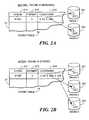
- Fig. 2illustrates in the same embodiment how a pattern for fault-tolerant storage for a chunk may be dynamically changed as a result of the addition of more storage.
- Fig. 2shows how a chunk physically stored on the storage devices may be laid out in a new pattern once additional storage is added to the overall system.
- the storage systemcomprises two storage devices 221 and 222 and the chunk data is physically mirrored onto the two storage devices at locations 2211 and 2221 to provide fault tolerance.
- a third storage device 223is added, and it become possible to store the chunk in a parity striped manner, a pattern which is more storage efficient than the mirrored pattern.
- the chunkis laid out in this new pattern in three physical locations 2311, 2321, and 2331, taking a much lower proportion of the available storage.
- the chunk table 21is updated to show the new layout is in three locations 212 and also the new chunk physical locations 2311, 2321, and 2331 are recorded 213.
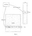
- Fig. 3shows a mature storage system, in accordance with an embodiment of the present invention, which has been functioning for some time. This illustrates how chunks may be physically stored over time on storage devices with varying storage capacities.
- the figureshows a storage system comprised of a 40GB storage device 31, an 80GB storage device 32 and a 120GB storage device 33. Initially chunks are stored in a fault tolerant stripe pattern 34 until the 40GB storage device 31 became full. Then, due to lack of storage space, new data is stored in a mirrored pattern 36 on the available space on the 80GB 32 and the 120GB 33 storage devices. Once the 80GB storage device 32 is full, then new data is laid out in a single disk fault tolerant pattern 37. Even though the storage devices comprise a single pool for storing data, the data itself, as stored in the chunks, has been stored in a variety of distinct patterns.
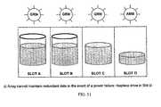
- Fig. 4illustrates another embodiment of the invention in which indicator states are used to warn of inefficient storage use and low levels of fault tolerance.
- all three storage devices 41, 42, and 45have free space and the indicator light 44 is green to show data is being stored in an efficient and fault-tolerant manner.
- the 40GB storage device 41has become full, and thus new data can be stored only on the two storage devices 42 and 43 with remaining free space in a mirrored pattern 46.
- the indicator light 44has turned amber.
- Fig. 4 (c)only the 120GB storage device 43 has free space remaining and so all new data can be stored only in a mirrored pattern on this one device 43. Because the fault-tolerance is less robust and the system is critically short of space, the indicator light 44 turns red to indicate the addition of more storage is necessary.
- an indicatoris provided for each drive/slot in the array, for example, in the form of a three-color light (e.g., green, yellow, red).
- the lightsare used to light the whole front of a disk carrier with a glowing effect. The lights are controlled to indicate not only the overall status of the system, but also which drive/slot requires attention (if any).
- Each three-color lightcan be placed in at least four states, specifically off, green, yellow, red. The light for a particular slot may be placed in the off state if the slot is empty and the system is operating with sufficient storage and redundancy so that no drive need be installed in the slot. The light for a particular slot may be placed in the green state if the corresponding drive is sufficient and need not be replaced.
- the light for a particular slotmay be placed in the yellow state if system operation is degraded such that replacement of the corresponding drive with a larger drive is recommended.
- the light for a particular slotmay be placed in the red state if the corresponding drive must be installed or replaced. Additional states could be indicated as needed or desired, for example, by flashing the light between on and off states or flashing the light between two different colors (e.g., flash between red and green after a drive has been replaced and re-layout of data is in progress). Additional details of an exemplary embodiment are described below.
- a single LCD displaycould be used to indicate system status and, if needed, a slot number that requires attention.
- other types of indicatorse.g., a single status indicator for the system (e.g., green/yellow/red) along with either a slot indicator or a light for each slot) could be used.
- Fig. 5is a block diagram of functional modules used in the storage, retrieval and re-layout of data in accordance with an exemplary form of the invention of the invention, such as discussed above in connections with Figs. 1-3 .
- the entry and exit point for communicationare the object interface 511 for passing objects to the system for storage or retrieving objects, the block interface 512, which makes the storage system appear to be one large storage device, and the CIFS interface 513, which makes the storage system appear to be a Windows file system.
- the Chunk Parser 52which performs the break up of the data into chunks and creates an initial entry into the object table 512 (as discussed above in connection with Fig. 1 ).
- chunksare then passed to the hash code generator 53, which creates the associated hash codes for each chunk and enters these into the object table so the chunks associated with each object are listed 512 (as discussed above in connection with in Fig. 1 ).
- the chunk hash numbersare compared with the entries in the chunk table 531. Where a match is found, the new chunk is discarded, as it will be identical to a chunk already stored in the storage system. If the chunk is new, a new entry for it is made in the chunk table 531, and the hashed chunk is passed to the physical storage manager 54.
- the physical storage managerstores the chunk hi the most efficient pattern possible on the available storage devices 571, 572, and 573 and makes a corresponding entry in the chunk table 531 to show where the physical storage of the chunk has occurred so that the contents of the chunk can be retrieved later 512 (as discussed above in connection with Fig. 1 ).
- the retrieval of data in Fig. 5 by the object 511, block 512 or CIFS 513 interfaceis performed by a request to the retrieval manager 56, which consults the object table 521 to determine which chunks comprise the object and then requests these chunks from the physical storage manager 54.
- the physical storage manager 54consults the chunk table 531 to determine where the requested chunks are stored and then retrieves them and passes the completed data (object) back to the retrieval manager 56, which returns the data to the requesting interface.
- the fault tolerant manager (FTL) 55also included in Fig. 5 is the fault tolerant manager (FTL) 55, which constantly scans the chunk table to determine if chunks are stored in the most efficient manner possible.
- FTLfault tolerant manager
- the FTLwill request the physical storage manager 54 to create a new layout pattern for the chunk and update the chunk table 531. This way all data continues to remain stored in the most efficient manner possible for the number of storage devices comprising the array (as discussed above in connection with Figs. 2 and 3 ).
- a Zonehas the effect of hiding redundancy and disk re-layout from the actual data being stored on the disk. Zones allow additional layout methods to be added and changed without affecting the user of the zone.
- ZonesThe storage array lays out data on the disk in virtual sections called Zones.
- a Zonestores a given and fixed amount of data (for example 1 G Bytes).
- a zonemay reside on a single disk or span across one or more drives.
- the physical layout of a Zoneprovides redundancy in the form specified for that zone.
- Fig. 6shows an example in which mirroring is used in an array containing more than two drives.
- Fig. 7shows some example zones using different layout schemes to store their data. The diagram assumes a zone stores 1 GB of data. Note the following points:
- Each diskis split into a set of equal-sized Regions.
- the size of a Regionis much smaller than a Zone and a Zone is constructed from one or more regions from one or more disks.
- the size of a Regionis typically a common factor of the different Zone sizes and the different number of disks supported by the array.
- Regionsare 1/12 the data size of a Zone.
- the following tablelists the number of Regions/Zone and the number of Regions/disk for various layouts. The following examples do not form part of the claimed invention, but represent examples which are useful for understanding the invention. Layont Method Number of regions/zone Number of regions/disk 1 drive mirror 24 24 2 drive mirror 24 12 3 drive stripe 18 6 4 drive stripe 16 4
- Individual Regionscan be marked as used, free or bad.
- a ZoneWhen a Zone is created, a set of free Regions from the appropriate disks are selected and logged in a table. These Regions can be in any arbitrary order and need not be contiguous on the disk.
- the accessis redirected to the appropriate Region. Among other things, this allows data re-layout to occur in a flexible and efficient manner. Over time, the different sized Zones will likely cause fragmentation to occur, leaving many disk areas too small to hold a complete Zone. By using the appropriate Region size, all gaps left by fragmentation will be at least one Region in size, allowing easy reuse of these small gaps with out having to de-fragment the whole disk.
- a fixed sequence of expansion and contractionmay be enforced. For example, if two drives are suddenly added, the expansion of a zone may go through an intermediate expansion as though one drive was added before a second expansion is performed to incorporate the second drive. Alternatively, expansion and contraction involving multiple drives may be handled atomically, without an intermediate step.
- Drive contractiontakes place when a disk is either removed or fails. In such a case, the array contracts the data to get all zones back into a redundant state if possible.
- Drive contractionis slightly more complex than expansion as there are more choices to make. However, transitions between layout methods happen in a similar way to expansion, but in reverse. Keeping the amount of data to be reproduced to a minimum allows redundancy to be achieved as quickly as possible. Drive contraction generally precedes one zone at a time while space is available until all zones are re-layed out. Generally speaking, only data which resides on the removed or failed disk will be rebuilt.
- Zone type missing data Condition ActionAny No Space available for zone re-layout Leave zone in degraded state until new disk added or removed disk is replaced.
- Single drive mirror Data inconsistent Lock down system and wait for reset or for the missing drive to be replacedDual Drive Mirror 1 disk left in system Convert to single drive mirror Space only available on drive that contains remaining data 2 or 3 disks left in system with space is available Reconstruct mirror on another drive 3 Drive Striping 2 disks left in system with space available Convert to 2 drive mirroring 3 disks left in system with space available Reconstruct missing stripe segment on the third drive 4 Drive Striping 3 disks left in system with space available Convert to 3 drive striping
- dual drive mirrorZone B
- three drive stripeZone C
- Drive 3if any of Drives 0-2 are lost, provided there is sufficient space available on Drive 3.
- Zone reconstructionoccurs when a drive has been removed and there is enough space on the remaining drives for ideal zone re-layout or the drive has been replaced with a new drive of larger size.
- four -drive-reconstructioncan only occur if the removed drive is replaced by another drive.
- the reconstructionconsists of allocating six regions on the new drive and reconstructing the missing data from the other three region sets.
- the arrayWhen a drive is removed and there is no room for re-layout, the array will continue to operate in degraded mode until either the old drive is plugged back in or the drive is replaced with a new one. If a new one is plugged in, then the drive set should be rebuilt. In this case, data will be re-laid out. If the old disk is placed back into the array, it will no longer be part of the current disk set and will be regarded as a new disk. However, if a new disk is not placed in the array and the old one is put back in, the old one will still be recognized as being a member of the disk set, albeit an out of date member.
- any zones that have already been re-laid outwill keep their new configuration and the regions on the old disk will be freed. Any zone that has not been re-laid out will still be pointing at the appropriate regions of the old disk.
- these zonesneed to be refreshed. Rather than logging every write that has occurred, degraded regions that have been modified may be marked. In this way, when the disk is replaced, only the regions that have been modified need to be refreshed.
- zones that have been written tomay be placed further up the priority list for re-layout. This should reduce the number of regions that need to be refreshed should the disk be replaced.
- a timeoutmay also be used, after which point the disk, even if replaced, will be wiped. However, this timeout could be quite large, possibly hours rather than minutes.
- one problem with a standard RAID systemis that it is possible for disc-surface corruption to occur on an infrequently used area of the disk array. In the event that another drive fails, it is not always possible to determine that corruption has occurred. In such a case, the corrupted data may be propagated and preserved when the RAID array rebuilds the failed drive.
- the hash mechanism discussed aboveprovides an additional mechanism for data corruption detection over that which is available under RAID.
- a hash valueis computed for the chunk and stored. Any time the chunk is read, a hash value for the retrieved chunk can be computed and compared with the stored hash value. If the hash values do not match (indicating a ' corrupted chunk), then chunk data can be recovered from redundant data.
- a regular scan of the diskswill be performed to find and correct corrupted data as soon as possible. It will also, optionally, allow a check to be performed on reads from the array.
- the storage arrayconsists of one or more drive slots.
- Each drive slotcan either be empty or contain a hard disk drive.
- Each drive slothas a dedicated indicator capable of indicating four states: Off, OK, Degraded and Fail.
- the statesare interpreted generally as follows: Indicator State Meaning for Array User Off Drive slot is empty and is available for an additional drive to be inserted. OK Drive in slot is functioning correctly.
- Degraded Action by userrecommend: if slot is empty, add a drive to this slot; if slot contains a drive, replace drive with another, higher-capacity drive.
- red/amber/green light emitting diodesare used as the indicators.
- the LEDsare interpreted generally as follows: LED state Indicator State Example circumstances under which state may occur Figures Off Off Slot is empty. Array has available space. 9,10,12 Green OK Drive is functioning correctly, array data is redundant and array has available disk space. 9,10,11,12 Amber Degraded Array is approaching a Fail condition; Not enough space to maintain redundant data in the event of a disc failure. 11 Red Fail Disk in this slot has failed and must be replaced; the array does not have enough space to maintain redundant data storage and more space must be added. 10,12
- Fig. 9shows an exemplary array having available storage space and operating in a fault-tolerant manner, in accordance with an exemplary embodiment of the present invention.
- Slots B, C, and Dare populated with storage devices, and there is sufficient storage space available to store additional data redundantly.
- the indicators for slots B, C, and Dare green (indicating that these storage devices are operating correctly, the array data is redundant, and the array has available disk space), and the indicator for slot A is off (indicating that no storage device needs to be populated in slot A).
- Fig. 10shows an exemplary array that does not have enough space to maintain redundant data storage and more space must be added, in accordance with an exemplary embodiment of the present invention.
- Slots B, C, and Dare populated with storage devices. The storage devices in slots C and D are full. The indicators for slots B, C, and D are green (indicating that these storage devices are operating correctly), and the indicator for slot A is red (indicating that the array does not have enough space to maintain redundant data storage and a storage device should be populated in slot A).
- Fig. 11shows an exemplary array that would be unable to maintain redundant data in the event of a failure, in accordance with an exemplary embodiment of the present invention.
- Slots A, B, C, and Dare populated with storage devices.
- the storage devices in slots C and Dare full.
- the indicators for slots A, B, and Care green (indicating that they are operating correctly), and the indicator for slot D is amber (indicating that the storage device in slot D should be replaced with a storage device having greater storage capacity).
- Fig. 12shows an exemplary array in which a storage device has failed, in accordance with an exemplary embodiment of the present invention.
- Slots B, C, and Dare populated with storage devices.
- the storage device in slot Chas failed.
- the indicators for slots B and Dare green (indicating that they are operating correctly), the indicator for slot C is red (indicating that the storage device in slot C should be replaced), and the indicator for slot A is off (indicating that no storage device needs to be populated in slot A).
- the software designis based on six software layers, which span the logical architecture from physically accessing the disks to communicating with the host computing system.
- a file systemresides on a host server, such as a Windows, Linux, or Apple server, and accesses the storage array as a USB or iSCSI device.
- Physical disk requests arriving over the host interfaceare processed by the Host Request Manager (HRM).
- HRMHost Request Manager
- a Host I/O interfacecoordinates the presentation of a host USB or iSCSI interface to the host, and interfaces with the HRM.
- the HRMcoordinates data read/write requests from the host I/O interface, dispatches read and write requests, and co-ordinates the retiring of these requests back to the host as they are completed.
- An overarching aim of the storage arrayis to ensure that once data is accepted by the system, it is stored in a reliable fashion, making use of the maximum amount of redundancy the system currently stores. As the array changes physical configuration, data is re-organized so as to maintain (and possibly maximize) redundancy. In addition, simple hash based compression is used to reduce the amount of storage used.
- Disksmay be attached via various interfaces, such as ATA tunneled over a USB interface.
- Sectors on the disksare organized into regions, zones, and clusters, each of which has a different logical role.
- Regionsrepresent a set of contiguous physical blocks on a disk. On a four drive system, each region is 1/12 GB in size, and represents minimal unit of redundancy. If a sector in a region is found to be physically damaged, the whole region will be abandoned.
- Zonesrepresent units of redundancy.
- a zonewill consist of a number of regions, possibly on different disks to provide the appropriate amount of redundancy. Zones will provide 1GB of data capacity, but may require more regions in order to provide the redundancy. 1 GB with no redundancy require one set of 12 regions (1GB); a 1GB mirrored zone will require 2 sets of 1 GB regions (24 regions); a 1GB 3-disk stripped zone will require 3 sets of 0.5GB regions (18 regions). Different zones will have different redundancy characteristics.
- Clustersrepresent the basic unit of compression, and are the unit size within zones. They are currently 4KB: 8 x 512 byte sectors in size. Many clusters on a disk will likely contain the same data.
- a cluster access table(CAT) is used to track the usage of clusters via a hashing function. The CAT translates between logical host address and the location of the appropriate cluster in the zone.
- a hash functionis used to see if the data is already present on the disk. If so, the appropriate entry in the CAT table is set to point to the existing cluster.
- the CAT tableresides in its own zone. If it exceeds the size of the zone, an additional zone will be used, and a table will be used to map logical address to the zone for that part of the CAT. Alternatively, zones are pre-allocated to contain the CAT table.
- journal managerIn order to reduce host write latency and to ensure data reliability, a journal manager will record all write requests (either to disk, or to NVRAM). If the system is rebooted, journal entries will be committed on reboot.
- Disksmay come and go, or regions may be retired if they are found to have corruption. In either of these situations, a layout manager will be able to re-organize regions within a zone in order to change its redundancy type, or change the regional composition of a zone (should a region be corrupted).
- a garbage collector(either located on the host or in firmware) will analyze the file system to determine which clusters have been freed, and remove them from the hash table.
- Layer 5Garbage collector, Host Interface (USB/iSCSI)
- Layer 4Host request manager
- Layer 3CAT
- HASHHost request manager
- Layer 2Zones manager. Allocates/frees chunks of sectors called Zones. Knows about SDM, DDM, SD3 etc in order to deal with errors and error recovery.
- Layout Manager Layer 1Read/write physical clusters/sectors. Allocates Regions per disk Layer 0: Disk access drivers
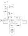
- Fig. 13shows a module hierarchy representing the different software layers and how they relate to one another.
- Software layeringis preferably rigid in order to present clear APIs and delineation.
- the Garbage Collectorfrees up clusters which are no longer used by the host file system. For example, when a file is deleted, the clusters that were used to contain the file are preferably freed.
- the Journal Managerprovides a form of journaling of writes so that pending writes are not lost in the case of a power failure or other error condition.
- the Layout Managerprovides run-time re-layout of the Zones vis-à-vis their Regions. This may occur as a result of disk insertion/removal or failure.
- the Cluster Managerallocates clusters within the set of data Zones.
- the Disk Utilization Daemonchecks for free disk space on a periodic basis.
- the Lock Tabledeals with read after write collision issues.
- the Host Request Managerdeals with the read/write requests from the Host and Garbage Collector. Writes are passed to the Journal Manager, whereas Reads are processed via the Cluster Access Table (CAT) Management layer.
- CATCluster Access Table
- the systemoperates on a cluster of data at any time (e.g., 8 physical sectors), and this is the unit that is hashed.
- the SHA1 algorithmis used to generate a 160-bit hash. This has a number of benefits, including good uniqueness, and being supported on-chip in a number of processors. All 160-bits will be stored in the hash record, but only the least significant 16-bits will be used as an index into a hash table. Other instances matching the lowest 16-bits will be chained via a linked-list.
- hash analysisis not permitted to happen when writing a cluster to disk. Instead, hash analysis will occur as a background activity by the hash manager.
- Write requestsare read from the journal's write queue, and are processed to completion. In order to ensure data consistency, writes must be delayed if a write operation is already active on the cluster. Operations on other clusters may proceed un-impeded.
- the data being writtenwill need to be merged with the existing data stored in the cluster.
- the CAT entry for the clusteris located.
- the hash key, zone and cluster offset informationis obtained from this record, which can then be used to search the hash table to find a match. This is the cluster.
- the hash tableit might well be necessary to doubly hash the hash table; once via the SHA1 digest, and then by the zone/cluster offset to improve the speed of lookup of the correct hash entry. If the hash record has already been used, the reference count is decremented. If the reference count is now zero, and there is no snapshot referenced by the hash entry, the hash entry and cluster can be freed back to their respective free lists.
- the original cluster datais now merged with the update section of the cluster, and the data is re-hashed.
- a new clusteris taken off the free-list, the merged data is written to the cluster, new entry is added to the hash table, and the entry in the CAT table is updated to point to the new cluster.
- the entryis also added to an internal queue to be processed by a background task.
- This taskwill compare the newly added cluster and hash entry with other hash entries that match the hash table row address, and will combine records if they are duplicates, freeing up hash entries and CAT table entries as appropriate. This ensures that write latency is not burdened by this activity. If a failure (e.g., a loss of power) occurs during this processing, the various tables can be deleted, with a resulting loss of data.
- the tablesshould be managed in such a way that the final commit is atomic or the journal entry can be re-run if it did not complete fully.
- Read requestsare also processed one cluster (as opposed to "sector") at a time. Read requests do not go through the hash-related processing outlined above. Instead, the host logical sector address is used to reference the CAT and obtain a Zone number and cluster offset into the Zone. Read requests should look up the CAT table entry in the CAT Cache, and must be delayed in the write-in-progress bit is set. Other reads/writes may proceed un-impeded. In order to improve data integrity checking, when a cluster is read, it will be hashed, and the hash compared with the SHA1 hash value stored in the hash record. This will require using the hash, zone and cluster offset as a search key into the hash table.
- Clustersare allocated to use as few Zones as possible. This is because Zones correspond directly to disk drive usage. For every Zone, there are two or more Regions on the hard drive array. By minimizing the number of Zones, the number of physical Regions is minimized and hence the consumption of space on the hard drive array is reduced.
- the Cluster Managerallocates cluster from the set of Data Zones.
- a linked listis used to keep track of free clusters in a Zone.
- the free cluster informationis stored as a bit map (32KB per Zone) on disk.
- the linked listis constructed dynamically from the bitmap. Initially, a linked list of a certain number of free clusters is created in memory. When clusters are allocated, the list shrinks. At a predetermined low-water mark, new linked list nodes representing free clusters are extracted from the bitmap on disk. In this way, the bitmap does not need to be parsed in order to find a free cluster for allocation.
- the hash tableis a 64K table of records (indexed by the lower 16 bits of the hash) and has the following format: Offset Size in bits Name Value/Valid Range Description 0 160 sha1Hash The complete SHA1 hash digest 16 refCount Number of instances of this hash; what do we do if we get beyond 16 bits? 18 Cluster offset Cluster offset within zone 14 Zone # Zone# containing this cluster 8 snapshot One bit per snapshot instance to indicate that this cluster entry is used by that snapshot. This model supports 8 snapshots (possible only 7)
- a cluster of all zerosmay be fairly common, so the all-zeros case may be treated as a special case, for example, such that it can never be deleted (so wrapping the count would not be a problem).
- a linked list of free hash recordis used when the multiple hashes have the same least significant hash, or when two hash entries point to different data clusters. In either case, a free hash record will be taken from the list, and linked via the pNextHash pointer.
- the hash managerwill tidy up entries added to the hash table, and will combine identical clusters on the disk.
- a messagewill be posted to the hash manager. This will be done automatically by the hash manager.
- the hash managerwill process entries on its queue. It will compare the full hash value to see if it matches any existing hash records. If it does, it will also compare the complete cluster data. If the clusters match, the new hash record can be discarded back to the free queue, the hash record count will be incremented, and the duplicate cluster will be returned to the cluster free queue.
- the hash managermust take care to propagate the snapshot bit forward when combining records.
- a Cluster Access Tablecontains indirect pointers. The pointers point to data clusters (with 0 being the first data cluster) within Zones.
- One CAT entryreferences a single data cluster (tentatively 4KB in size).
- CATsare used (in conjunction with hashing) in order to reduce the disk usage requirements when there is a lot of repetitive data.
- a single CATalways represents a contiguous block of storage.
- CATsare contained within non-data Zones. Each CAT entry is 48-bits. The following table shows how each entry is laid out (assuming each data Zone contains 1 GB of data): Bits 0-17 Bits 18-31 Bits 32-47 Bits 48-63[..] Offset of data cluster within Zone Zone# containing data Hash key Reserved.
- Candidatesinclude garbage collector write-bit; snapshot bits; snapshot table hash key
- the CAT table for a 2TB arrayis currently ⁇ 4GB in size. Each CAT entry points to a Zone which contains the data and the number of the Zone.
- Fig. 14shows how the CAT is used to access a data clusters in a Zone. Redundant data is referenced by more than one entry in the CAT. Two logical clusters contain the same data, so their CAT entries are pointed to the same physical cluster.
- the Hash Key entrycontains the 16-bit extract of the 160-bit SHA1 hash value of the entire cluster. This entry is used to update the hash table during a write operation.
- a Host Logical Sector Translation Tableis used to translate a Host Logical Sector Address into a Zone number.
- the portion of the CAT that corresponds to the Host Logical Sector Addresswill reside in this zone.
- each CAT entryrepresents a cluster size of 4096 bytes. This is eight 512 byte sectors.
- the followingshows a representation of the host logical sector translation table: Start Host Logical Sector Address End Host Logical Sector Address Zone # of CAT 0 (cluster #0) 1431655759 (cluster #178956969) 1431655760 (cluster #178956970) ...
- Zonescan be pre-allocated to hold the entire CAT. Alternatively, Zones can be allocated for the CAT as more entries to the CAT are required. Since the CAT maps the 2TB virtual disk to the host sector address space, it is likely that a large part of the CAT will be referenced during hard disk partitioning or formatting by the host. Because of this, the Zones may be pre-allocated.
- the CATis a large 1GB/zone table.
- the working set of clusters being usedwill be a sparse set from this large table.
- active entriesmay be cached in processor memory rather than always reading them from the disk.
- the cacheneeds to be at least as large at the maximum number of outstanding write requests.
- Entries in the cachewill be a cluster size (ie. 4K). There is a need to know whether there is a write-in-progress in operation on a cluster. This indication can be stored as a flag in the cache entry for the cluster.
- the following tableshows the format of a CAT cache entry: Bits 0-17 Bits 18-31 Bits 32-47 Bit 48-63 Offset of data cluster within Zone Zone# containing data Hash key Bit 48: Write-in-progress Bit 49: Dirty
- the write-in-progress flag in the cache entryhas two implications. First, it indicates that a write is in progress, and any reads (or additional writes) on this cluster must be held off until the write has completed. Secondly, this entry in the cache must not be flushed while the bit is set. This is partly to protect the state of the bit, and also to reflect the fact that this cluster is currently in use. In addition, this means that the size of the cache must be at least as large as the number of outstanding write operations.
- the cachecan be a write-delayed cache. It is only necessary to write a cache entry back to disk when the write operation has completed, although it might be beneficial to have it written back earlier.
- a hash function or other mechanismcould be used to increase the number of outstanding write entries that can be hashed.
- CAT Entry 682CAT Entry 683 (partial entry of first 2 words) Write-in-progress bit array [682 bits] : bits 0-255 Write-in-progress bit array bits 256-511 Write-in-progress bit array 512-682 + spare bits Dirty count Reserved
- the table sizewould be 4096 + 96 (4192 bytes). Assuming it is necessary to have a cache size of 250 entries, the cache would occupy approximately 1MB.
- the caching lookup routineshould do this prior to loading an entry and should load the required CAT cluster.
- the hostWhen the host sends a sector (or cluster) read request, it sends over the logical sector address.
- the logical sector addressis used as an offset into the CAT in order to obtain the offset of the cluster in the Zone that contains the actual data that is requested by the host.
- the resultis a Zone number and an offset into that Zone. That information is passed to the Layer 2 software, which then extracts the raw cluster(s) from the drive(s).
- the journal manageris a bi-level write journaling system.
- An aim of the systemis to ensure that write requests can be accepted from the host and quickly indicate back to the host that the data has been accepted while ensuring its integrity.
- the systemneeds to ensure that there will be no corruption or loss of any block level data or system metadata (e.g., CAT and Hash table entries) in the event of a system reset during any disk write.
- block level data or system metadatae.g., CAT and Hash table entries
- the J1 journal managercaches all write requests from the hosts to disk as quickly as possible. Once the write has successfully completed (i.e., the data has been accepted by the array); the host can be signaled to indicate that the operation has completed.
- the journal entryallows recovery of write requests when recovering from a failure. Journal records consist of the data to be written to disk, and the meta-data associated with the write transaction.
- the data associated with the writewill be written to free clusters. This will automatically mirror the data. Free clusters will be taken from the free cluster list. Once the data is written, the free cluster list must be written back to disk.
- journal recordwill be written to a journal queue on a non-mirrored zone.
- Each recordwill be a sector in size, and aligned to a sector boundary in order to reduce the risk that a failure during a journal write would corrupt a previous journal entry.
- Journal entrieswill contain a unique, incrementing sequence count at the end of the record so that the end of a queue can easily be identified.
- Journal write operationswill happen synchronously within a host queue processing thread. Journal writes must be ordered as they are written to disk, so only one thread may write to the journal as any time.
- the address of the journal entry in the J1 tablecan be used as a unique identifier so that the J1 journal entry can be correlated with entries in the J2 journal.
- a transaction completion notificationwill be posted to the host completion queue. Now the write operation can be executed. It is important to ensure that any subsequent reads to a cluster before the journal write has completed are delayed.
- journal recordwill be aligned to a sector boundary.
- a journal recordmight contain an array of zone/offset/size tuples.
- FIG. 15shows a journal table update in accordance with an exemplary form of the present invention. Specifically, when a host write request is received, the journal table is updated, one or more clusters are allocated, and data is written to the cluster(s).
- Host journal requestsare processed. These cause clusters to be written, and also cause updates to meta-data structure which must be shadowed back to disk (for example, the CAT table). It is important to ensure that these meta-data structures are correctly written back to disk even if a system reset occurs. A low level disk I/O write (J2) journal will be used for this.
- the J2 journalexists logically at layer 3. It is used to journal meta-data updates that would involve writes through the zone manager. When playback of a journal entry occurs, it will use zone manager methods. The journal itself can be stored in a specialized region. Given the short lifespan of journal entries, they will not be mirrored.
- J2 journalA simple approach for the J2 journal is to contain a single record. As soon as the record is committed to disk, it is replayed, updating the structures on disk. It is possible to have multiple J2 records and to have a background task committing updating records on disks. In this case, close attention will need to be paid to the interaction between the journal and any caching algorithms associated with the various data structures.
- journal entriesshould be committed as soon as they have been submitted.
- J2 journalis analyzed, and any records will be replayed. If a journal entry is correlated with a J1 journal entry, the J1 entry will be marked as completed, and can be removed. Once all J2 journal entries have been completed, the meta-data is in a reliable state and any remaining J1 journal entries can be processed.
- the J2 journal recordincludes the following information:
- This schemecould operate similarly to the J1 journal scheme, for example, with a sequence number to identify the end of a J2 journal entry and placing J2 journal entries on sector boundaries.
- J1 data pointer indicatorIf the J1 data pointer indicator is set, then this specific operation would point to a J1 journal record. The host supplied write data would not have to be copied into our journal entry.
- the operation arrayshould be able to be defined as a fixed size as the maximum number of operations in a journal record is expected to be well understood.
- the J2 journalcould store the whole sector that was written so that the sector could be re-written from this information if necessary.
- a CRC calculated for each modified sectorcould be stored in the J2 record and compared with a CRC computed from the sector on disk (e.g., by the zone manager) in order to determine whether a replay of the write operation is required.
- the different journalscan be stored in different locations, so there will be an interface layer provided to write journal records to backing store.
- the locationshould be non-volatile.
- Two candidatesare hard disk and NVRAM. If the J1 journal is stored to hard disk, it will be stored in a J1 journal non-mirrored zone. The J1 journal is a candidate for storing in NVRAM.
- the J2 journalshould be stored on disk, although it can be stored in a specialized region (i.e., not redundant, as it has a short lifespan).
- An advantage of storing the J2 journal on diskis that, if there is a system reset during an internal data structure update, the data structures can be returned to a consistent state (even if the unit is left un-powered for a long period of time).
- Zones Managerallocates Zones that are needed by higher level software. Requests to the ZM include:
- the ZMmanages the redundancy mechanisms (as a function of the number of drives and their relative sizes) and handles mirroring, striping, and other redundancy schemes for data reads/writes.
- the ZMWhen the ZM needs to allocate a Zone, it will request an allocation of 2 or more sets of Regions. For example, a Zone may be allocated for 1 GB of data. The Regions that make up this Zone will be able to contain 1 GB of data including redundancy data. For a mirroring mechanism, the Zone will be made up of 2 sets of Regions of 1 GB each. Another example, a 3-disk striping mechanism utilize 3 sets of Regions of 1/2 GB each.
- the ZMuses the ZR translation table (6) to find out the location (drive number and start Region number) of each set of Regions that makes up the Zone. Assuming a 1/12GB Region size, a maximum of 24 Regions will be needed. 24 Regions make up 2x 1 GB Zones. So the ZR translation table contains 24 columns that provide drive/region data.
- the ZMworks generally as follows:
- the ZMWhen a read/write request comes in, the ZM is provided with the Zone number and an offset into that Zone. The ZM looks in the ZR translation table to figure out the redundancy mechanism for that Zone and uses the offset to calculate which Drive/Region contains the sector that must be read/written. The Drive/Region information is then provided to the L1 layer to do the actual read/write. An additional possible entry in the Usage column is "Free". "Free" indicates that the Zone is defined but currently not used.
- the cluster managerallocates and de-allocates clusters within the set of data Zones.
- the Layout Managerprovides run-time re-layout of the Zones vis-à-vis their Regions. This may occur as a result of disk insertion/removal or failure.
- the Layer 1 (L1) softwareknows about physical drives and physical sectors. Among other things, the L1 software allocates Regions from physical drives for use by the Zones Manager. In this exemplary, form of the invention each Region has a size of 1/12GB (i.e., 174763 sectors) for a four-drive array system. A system with a larger maximum number of drives (8, 12 or 16) will have a different Region size.
- This Region schemeallows us to provide better utilization of disk space when Zones get moved around or reconfigured e.g., from mirroring to striping.
- the L1 softwarekeeps track of available space on the physical drives with a bitmap of Regions. Each drive has one bitmap. Each Region is represented by two bits in the bitmap in order to track if the Region is free, used, or bad.
- ZML2 software
- Requests to L1include:
- the free region bitmapmay be large, and therefore searches to find the free entry (worst case is that no entries are free) may be slow.
- part of the bitmapcan be preloaded into memory, and a linked list of free regions can be stored in memory. There is a list for each active zone. If a low water mark on the list is reached, more free entries can be read from the disk as a background activity.
- the Disk Manageroperates at layer 0. As shown in the following table, there are two sub-layers, specifically an abstraction layer and the device drivers that communicate with the physical storage array.
- Layer 0aAbstraction Layer 0b : OS interface to device drivers and device drivers Physical Storage Array Hardware
- the Device Drivers layermay also contain several layers. For example, for a storage array using USB drives, there is an ATA or SCSI stack on top of the USB transport layer.
- the abstraction layerprovides basic read/write functions that are independent of the kinds of drives used in the storage array.
- Disk access ratesmay be one of the key performance bottlenecks in our system. We will want to ensure that the disk interface is kept as busy as possible at all times so as to reduce general system latency and improve performance. Requests to the disk interface should have an asynchronous interface, with a callback handler to complete the operation when the disk operation has finished. Completion of one disk request will automatically initiate the next request on the queue. There may be one queue per drive or one queue for all drives.
- Layer 1will reference drives as logical drive numbers.
- Layer 0will translate logical drive numbers to physical drive references (e.g., /dev/sda or file device number as a result of an open() call). For flexibility (expansion via USB), there should be a queue for each logical drive.
- each diskis divided into Regions of fixed size.
- each Regionhas a size of 1/12GB (i.e., 174763 sectors) for a four-drive array system.
- a system with a larger maximum number of drives (8, 12 or 16)will have a different Region size.
- Region numbers 0 and 1are reserved for use by the Regions Manager and are not used for allocation.
- Region number 1is a mirror of Region number 0. All internal data used by the Regions Manager for a given hard disk is stored in Region numbers 0 and 1 of this hard disk. This information is not duplicated (or mirrored) to other drives. If there are errors in either Region 0 or 1, other Regions can be allocated to hold the data.
- the Disk Information Structurepoints to these Regions.
- Each diskwill contain a DIS that identifies the disk, the disk set to which it belongs, and the layout information for the disk.
- the first sector on the hard diskis reserved.
- the DISis stored in the first non-bad cluster after the first sector.
- the DISis contained in 1KB worth of data.
- the copies of the DISwill be stored on the disk to which it belongs.
- every disk in the systemwill contain a copy of all the DISs of the disks in the system.
- the following tableshows the DIS format: Offset Size Name Value/Valid Range Description 0 32 bytes disStartSigniture "_DISC Identifies the cluster as INFORMATION CLUSTER START_" being a possible disc information cluster.
- WORD16disVersion Binary non-zero number Identifies the structure version. This value is only changed when a material change is made to the structure layout or content meaning that makes it incompatible with previous versions of the Firmware.
- WORD16disClusterSize Binary non-zero number The number of 512 byte sectors that make a cluster on this disc.
- WORD32disCRC CRC-32 CRC of the DIS structure.
- WORD32disSize !!!
- Size of DIS cluster(in bytes) WORD32 disDiskSet
- the disk set this diskbelongs to WORD32 disDriveNumber 0 to 15
- the drive number within the disk setWORD32 disSystemUUID UUID of the box this disk belongs to WORD64 disDiskSize Size of the disk in number of sectors
- WORD32 disRegionSize size of Regions in number of sectorsWORD64 disRegionsStart Sector offset to the start of the first Region on the disk WORD64 disCopyOffset Sector offset to where the copy of this DIS is stored.
- the disCopyOffset of each DISreference each other WORD64 disDISBackup Sector offset to the table containing the copies of the DISs of all the disks WORD32 disDISBackupSize Number of DISs in the DIS Backup section WORD32 disRIS0Region Region number of where first copy of the RIS is stored WORD32 disRIS0Offset Number of sectors offset within the Region to the sector where the Regions Information Structure is located WORD32 disRIS1Region For the copy of the RIS WORD32 disRIS1Offset For the copy of the RIS WORD32 disZIS0Region Region number of Region where the Zones Information Structure is located. This is ONLY used if there is a ZTR on this disk. Otherwise, it is zero.
- WORD32 disZIS0Offset Offset to the ZIS within the regionWORD32 disZIS1Region Region number of Region where a copy of the ZIS is located. This is ONLY used in a single drive system. In other cases, this entry is 0. WORD32 disZIS1Offset Offset to the ZIS within the region
- Regions Managerstores its internal data in a regions information structure.
- the following tableshows the regions information structure format:. Offset Size Name Value/Valid Range Description 0 WORD64 risSignature Indicates that this is a RIS WORD32 risSize Size Size of this structure (bytes) WORD32 risChecksum Checksum WORD32 risVersion Version of this table (and bitmap) WORD32 risDrive Logical Drive number WORD64 risStartSector Absolute start sector (in disk) of Regions utilization bitmap WORD32 risSectorOffset Sector offset of Regions utilization bitmap within the current Region WORD32 risSizeBitmap Size of bitmap (in bits?) WORD64 risNumberRegions Number of regions on this disk (also implies size of bitmap)
- the zones information structureprovides information on where the Zones Manager can find the Zones Table.
- WORD32ziNumberRegions Number of Regions used to contain each copy of the Zones Table. Equal to the number of Zones Table Nodes. 28 WORD32 ziStartOffset Byte offset pointing to start of linked list of Regions that are used to contain the Zones Table. Each entry in the linked list is called 'Zones Table Node" WORD32 ziNumberofZones Number of Zones (entries in Zones Table) in the system WORD32 ziZoneSize Size of zones in bytes
- High level information zonescontain the Zone tables and other tables used by the high level managers. These will be protected using mirroring.
- the following tableshows the zones table node format: Size Name Description WORD32 ztNextEntry Pointer to next entry in linked list WORD32 ztCount Count of this entry WORD64 ztRegion Region number
- Zones Information StructureFirst Zones Table Node (16bytes) ... Last Zones Table Node (16 bytes)
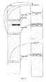
- Fig. 16shows the drive layout in accordance with an exemplary form of the invention.
- the first two regionsare copies of one another.
- a third (optional) Zones Table Regioncontains the Zone Tables.
- only two of the drivescontain a ZTR.
- two Regionsare used to hold the two (mirrored) copies of the ZTR.
- the DIScontains information on the location of the RIS and the ZIS. Note that the first copy of the RIS does not have to be in Region 0 (e.g., could be located in a different Region if Region 0 contains bad sectors).
- the Zones Managerneeds to load the Zones Tables on system start up. To do that, it extracts the Region number and offset from the DISs. This will point to the start of the ZIS.
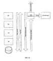
- Certain modulesstore their control structures and data tables in Zones. All control structures for modules in Layer 3 and higher are referenced from structures that are stored in Zone 0. This means, for example, that the actual CAT (Cluster Allocation Tables) locations are referenced from the data structures stored in Zone 0.
- the following tableshows the zone 0 information table format: Offset Size Name Value/Valid Range Description 0 WORD64 zitSignature Indisates that this is a ZIT WORD32 zitSize Size of this structure (bytes) WORD32 zitChecksum Checksum of this structure WORD32 zitVersion Version of this structure WORD32 zitCATLStartOffset Byte offset (within this Zone) of start of CAT linked list WORD32 zitCATSize Number of nodes in CAT linked list. Equal to number of Zones containing the CAT WORD64 zitCATAddressable The max LBA supported by the CAT.
- the CAT linked listis a linked list of nodes describing the Zones that contain the CAT.
- the following tableshows the CAT Linked List node format: Size Name Description WORD32 catllNextEntry Pointer to next entry in linked list WORD16 catllCount Count of this entry WORD 16 catllZone Zone number containing this portion of the CAT
- the hash table linked listis a linked list of nodes that describe the Zones which hold the Hash Table.
- the following tableshows the Hash Table Linked List node format: Size Name Description WORD32 htllNextEntry Pointer to next entry in linked list WORD16 htllCount Count of this entry WORD16 htllZone Zone number containing this portion of the hash table
- Fig. 17demonstrates the layout of Zone 0 and how other zones are referenced, in accordance with an exemplary form of the invention.
- a Redundant setis a set of sectors/clusters that provides redundancy for a set of data.
- Backing up a Regioninvolves copying the contents of a Region to another Region.
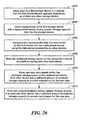
- the lower level software(Disk Manager or Device Driver) retries the read request two additional times after an initial failed attempt.
- the failure statusis passed back up to the Zones Manager.
- the Zones Managerattempts to reconstruct the data that is requested (by the read) from the redundant clusters in the disk array.
- the redundant datacan be either a mirrored cluster (for SDM, DDM) or a set of clusters including parity (for a striped implementation).
- the reconstructed datais then passed up back to the host. If the ZM is unable to reconstruct the data, then a read error is passed up back to the host.
- the Zones Managersends an Error Notification Packet to the Error Manager.
- Fig. 18demonstrates read error handling in accordance with an exemplary embodiment of the invention.
- the lower level software(Disk Manager or Device Driver) retries the write request two additional times after an initial failed attempt.
- the failure statusis passed back up to the Zones Manager.
- the Zones Managersends an Error Notification Packet to the Error Manager.
- Approach (a)is problematic because a write status would likely have already been sent to the host as a result of a successful write of the Journal, so the host may not know that there has been an error.
- An alternativeis to report a failure with a read, but allow a write. A bit in the CAT could be used to track that the particular LBA should return a bad read.
- Fig. 19demonstrates write error handling in accordance with an exemplary form of the invention.
- EMError Manager
- the Error Managerchecks the cluster to see if it is really bad. If so, the entire region is considered bad. The contents of the Region are copied over to a newly allocated Region on the same disk. The current Region is then marked BAD. While copying over the Region, the Error Manager will reconstruct data where necessary when it encounters bad sectors.
- Fig. 20is a logic flow diagram demonstrating backup of a bad Region by the Error Manager in accordance with an exemplary form of the invention.
- the EMdisables access to the clusters corresponding to this part of the Zone. It then updates the Zones Table to point to the newly allocated Regions. Subsequently, accesses to the clusters are re-enabled.
- This exemplary form of the inventionis designed to support eight snapshots (which allows use of one byte to indicate whether hash/cluster entries are used by a particular snapshot instance). There are two tables involved with snapshots:
- Clusters/hash entries that are not longer required by any snapshotsare freed by walking through the hash table and find any hash entries with the retiring snapshot bit set and clearing that bit. If the snapshot byte is now zero, the hash entry can be removed from the table and the cluster can be freed.
- the hash tablecan be walked as a background activity.
- a second CAT zonecould be written whenever the main CAT is being updated. These updates could be queued and the shadow CAT could be updated as another task. In order to snapshot, the shadow CAT becomes the snapshot CAT.
- a background processcan be kicked off to copy this snapshot table to a new zone become the new snapshot CAT.
- a queuecould be used so that the shadow CAT queue is not processed until the copy of the CAT had completed. If a failure were to occur before updating the shadow CAT (in which case entries in the queue may be lost), re-shadow from the primary CAT table could be performed before the array is brought online.
- garbage collectormay be used to free up clusters which are no longer used by the host file system (e.g., when a file is deleted).
- garbage collectionworks by finding free blocks, computing their host LSAs, and locating their CAT entries based on the LSAs. If there is no CAT entry for a particular LSA, then the cluster is already free. If, however, the CAT entry is located, the reference count is decremented, and the cluster is freed if the count hits zero.
- garbage collectionit may be difficult to distinguish a block that the host filesystem has in use from one that it has previously used and at some point marked free.
- the storage systemallocates a cluster for the data as well as a CAT entry to describe it. From that point on, the cluster will generally appear to be in use, even if the host filesystem subsequently ceases to use its block (i.e., the cluster will still be in use with a valid CAT entry).
- certain host filesystemsuse a bitmap to track its used disk blocks. Initially, the bitmap will indicate all blocks are free, for example, by having all bits clear. As the filesystem is used, the host filesystem will allocate blocks through use of its free block bitmap. The storage system will associate physical storage with these filesystem allocations by allocating clusters and CAT entries as outlined earlier. When the host filesystem releases some blocks back to its free pool, it simply needs to clear the corresponding bits in its free block bitmap.
- thiswill generally be manifested as a write to a cluster that happens to contain part of the host's free block bitmap, likely with no I/O to the actual cluster being freed itself (although there might be I/O to the freed cluster, for example, if the host filesystem were running in some enhanced security mode, in which case it would likely write zeros or a crypto strong hash of random data to the cluster in order to reduce the chance that stale cluster contents can be read by an attacker). Furthermore, there is no guarantee that the host filesystem will reuse blocks that it has previously freed when satisfying new allocation requests. Thus, if the host filesystem continues to allocate what from the storage system's point of view are new, i.e.
- the storage systemmay detect the release of host filesystem disk resources by accessing the host filesystem layout, parsing its free block bitmaps, and using that information to identify clusters that are no longer being used by the filesystem.
- the storage systemIn order for the storage system to be able to identify unused clusters in this way, the storage system must be able to locate and understand the free block bitmaps of the filesystem.
- the storage systemwill generally support a predetermined set of filesystems for which it "understands" the inner working sufficiently to locate and utilize the free block bitmaps. For unsupported filesystems, the storage system would likely be unable to perform garbage collection and should therefore only advertise the real physical size of the array in order to avoid being overcommitted.
- the filesystem's superblock(or an equivalent structure) needs to be located.
- the partition tablewill be parsed in an attempt to locate the OS partition. Assuming the OS partition is located, the OS partition will be parsed in an attempt to locate the superblock and thereby identify the filesystem type.
- the layoutcan be parsed to find the free block bitmaps.
- historical data of the host filesystem bitmapcan be kept, for example, by making a copy of the free block bitmap that can be stored in a private, non-redundant zone and performing searches using the copy. Given the size of the bitmap, information may be kept for a relatively small number of clusters at a time rather than for the whole bitmap.
- the current free block bitmapcan be compared, cluster-by-cluster, with the historical copy. Any bitmap entries transitioning from allocated to free can be identified, allowing the scavenging operation to be accurately directed to clusters that are good candidates for reclamation.
- the historical copycan be replaced with the current copy to maintain a rolling history of bitmap operations. Over time the copy of the free block bitmap will become a patchwork of temporally disjoint clusters, but since the current copy will always be used to locate free entries, this does not cause any problems.
- garbage collectioncan be a fairly expensive operation, and since even lightweight scavenging will consume back-end I/O bandwidth, garbage collection should not be overused.
- the garbage collectorshould be able to run in several modes ranging from a light background lazy scavenge to an aggressive heavyweight or even high priority scavenge. For example, the garbage collector could be run lightly when 30% of space is used or once per week at a minimum, run slightly more heavily when 50% of space is used, and run at a full high-priority scavenge when 90% or more of disk space is used.
- the aggressiveness of the garbage collectorcould be controlled by limiting it to a target number of clusters to reclaim and perhaps a maximum permissible I/O count for each collection run.
- the garbage collectorcould be configured to reclaim 1 GB using no more than 10,000 I/Os. Failure to achieve the reclaim request could be used as feedback to the collector to operate more aggressively next time it is run. There may also be a "reclaim everything" mode that gives the garbage collector permission to parse the entire host filesystem free block bitmap and reclaim all blocks that it possibly can. This might be done as a last ditch attempt to reclaim clusters when the array is (almost) completely full.
- the garbage collectormay be run periodically to apply its rules and may or may not decide to perform a scavenge operation. The scavenge operation should also be able to be explicitly requested from another module, for example the region manager when it is struggling to find clusters to build a region.
- the garbage collection functioncan be tied into the status indicator mechanism. For example, at some point, the storage system might be in a "red” condition, although an ongoing garbage collection operation might free up enough space to erase the "red” condition. Additional indicator states could be employed to show related status information (e.g., the red indicator light might be made to blink to indicate that a garbage collection operation is ongoing).
- Fig. 21is a schematic block diagram showing the relevant components of a storage array in accordance with an exemplary embodiment of the present invention.
- the storage arrayincludes a chassis 2502 over which a storage manager 2504 communicates with a plurality of storage devices 2508 1 -2508 N , which are coupled to the chassis respectively through a plurality of slots 2506 1 -2506 N .
- Each slot 2506 1 -2506 Nmay be associated with one or more indicators 2507 1 -2507 N .
- the storage manager 2504typically includes various hardware and software components for implementing the functionality described above.
- Hardware componentstypically include a memory for storing such things as program code, data structures, and data as well as a microprocessor system for executing the program code.
- a hot spare storage devicewill be maintained in a ready state so that it can be brought online quickly in the event another storage device fails.
- a virtual hot spareis created from unused storage capacity across a plurality of storage devices. Unlike a physical hot spare, this unused storage capacity is available if and when a storage device fails for storage of data recovered from the remaining storage device(s).
- the virtual hot spare featurerequires that enough space be available on the array to ensure that data can be re-laid out redundantly in the event of a disk failure.
- the storage systemtypically determines the amount of unused storage capacity that would be required for implementation of a virtual hot spare (e.g., based on the number of storage devices, the capacities of the various storage devices, the amount of data stored, and the manner in which the data is stored) and generates a signal if additional storage capacity is needed for a virtual hot spare (e.g., using green/yellow/red lights to indicate status and slot, substantially as described above).
- a recordis kept of how many regions are required to re-layout that zone on a per disk basis.
- Zone Type Stored On DisksComments Regions required if disk fails Disk 0 Disk 1 Disk 2 Disk 3 2 Dual Drive Mirror 0, 1 Reconstruct on disk 2 or 3 if 0 or 1 fails 12 12 0 0 3 Dual Drive Mirror 0,3 Reconstruct on disk 1 or 2 if 1 or 2 fails 12 0 0 12 5 Triple Drive Stripe 1,2,3 Reconstruct on disk 0 if 1, 2, or 3 fails 0 6 6 6 10 Four Drive Stripe 0, 1, 2, 3 Convert to triple drive strip across other three disks 2, 2, 2 2,2,2 2,2,2 2, 2, 2, 2
- Zone Type Stored On DisksComments Regions required if disk fails Disk 0 Disk 1 Disk 2 2 Dual Drive Mirror 0, 1 Reconstruct on disk 3 12 12 0 3 Dual Drive Mirror 0, 3 Reconstruct on disk 1 12 0 12 5 Triple Drive Stripe 1, 2, 3 Convert to dual drive mirror 6,6 6,6 6,6
- virtual hot spareis not available on an array with only 1 or 2 drives.
- the arraydetermines a re-layout scenario for each possible disk failure and ensure that enough space is available on each drive for each scenario.
- the information generatedcan be fed back into the re-layout engine and the zone manager so that the data can be correctly balanced between the data storage and the hot spare feature.
- the hot spare featurerequires enough spare working space regions on top of those calculated from the zone layout data so that re-layout can occur.
- Fig. 22is a logic flow diagram showing exemplary logic for managing a virtual hot spare in accordance with an exemplary form of the present invention.
- the logicdetermines a re-layout scenario for each possible disk failure.
- the logicdetermines the amount of space needed on each drive for re-layout of data redundantly in a worst case scenario.
- the logicdetermines the amount of spare working space regions needed for re-layout of data redundantly in a worst case scenario.
- the logicdetermines the total amount of space needed on each drive in order to permit re-layout of data redundantly in a worst case scenario (essentially the sum of the amount of space needed for re-layout and the amount of spare working space regions needed).
- the logicdetermines whether the storage system contains an adequate amount of available storage. If there is an adequate amount of available storage (YES in block 2112), then the logic iteration terminates in block 2199. If, however, there is an inadequate amount of available storage (NO in block 2112), then the logic determines which drive/slot requires upgrade, in block 2114. Then, in block 2116, the logic signals that additional storage space is needed and indicates which drive/slot requires upgrade. The logic iteration terminates in block 2199.
- Fig. 23is a logic flow diagram showing exemplary logic for determining a re-layout scenario for each possible disk failure, as in block 2102 of Fig. 22 , in accordance with an exemplary form of the present invention.
- the logicallocates a zone.
- the logicdetermines how many regions are required to re-layout that zone on a per-disk basis. The logic iteration terminates in block 2299.
- Fig. 24is a logic flow diagram showing exemplary logic for invoking the virtual hot spare functionality in accordance with an exemplary form of the present invention.
- the logicmaintains a sufficient amount of available storage to permit re-layout of data redundantly in the event of a worst case scenario.
- the logicUpon determining loss of a drive (e.g., removal or failure), in block 2304, the logic automatically reconfigures the one or more remaining drives to restore fault tolerance for the data, in block 2306. The logic iteration terminates in block 2399.
- Fig. 25is a logic flow diagram showing exemplary logic for automatically reconfiguring the one or more remaining drives to restore fault tolerance for the data, as in block 2306 of Fig. 24 , in accordance with an exemplary form of the present invention.
- the logicmay convert a first striped pattern across four or more storage devices to a second striped pattern across three or more remaining storage devices.
- the logicmay convert a striped pattern across three storage devices to a mirrored pattern across two remaining storage devices.
- the logicmay convert patterns in other ways in order to re-layout the data redundantly following loss of a drive.
- the logic iterationterminates in block 2499.
- the storage manager 2504typically includes appropriate components and logic for implementing the virtual hot spare functionality as described above.
- the logic described above for handling dynamic expansion and contraction of storagecan be extended to provide a dynamically upgradeable storage system in which storage devices can be replaced with a larger storage devices as needed, and existing data is automatically reconfigured across the storage devices in such a way that redundancy is maintained or enhanced and the additional storage space provided by the larger storage devices will be included in the pool of available storage space across the plurality of storage devices.
- the additional storage spacecan be used to improve redundancy for already stored data as well as to store additional data.
- an appropriate signalis provided to the user (e.g., using green/yellow/red lights substantially as described above), and the user can simply remove a storage device and replace it with a larger storage device.
- Fig. 26is a logic flow diagram showing exemplary logic for upgrading a storage device, in accordance with an exemplary embodiment of the present invention.
- the logicstores data on a first storage device in a manner that the data stored thereon appears redundantly on other storage devices.
- the logicdetects replacement of the first storage device with a replacement device having greater storage capacity than the first storage device.
- the logicautomatically reproduces the data that was stored on the first device onto the replacement device using the data stored redundantly on other devices.
- the logicmakes the additional storage space on the replacement device available for storing new data redundantly.
- the logicmay store new data redundantly within the additional storage space on the replacement device if no other device has a sufficient amount of available storage capacity to provide redundancy for the new data.
- the logicmay store new data redundantly across multiple storage devices if at least one other device has a sufficient amount of available storage capacity to provide redundancy for the new data.
- the storage manager 2504typically includes appropriate components and logic for implementing the dynamic upgrade functionality as described above.
- Embodiments of the present inventionmay be employed to provide storage capacity to a host computer, e.g., using a peripheral connect protocol in the manner described in my United States Provisional Patent Application No. 60/625,495, which was filed on November 5, 2004 in the name of Geoffrey S. Barrall, and is hereby incorporated herein by reference in its entirety.
- a hash algorithmmay not produce hash values that are strictly unique. Thus, is it conceivable for the hash algorithm to generate the same hash value for two chunks of data having non-identical content.
- the hash function(which generally incorporates the hash algorithm) typically includes a mechanism for confirming uniqueness. For example, in an exemplary embodiment of the invention as described above, if the hash value for one chunk is different than the hash value of another chunk, then the content of those chunks are considered to be non-identical.
- the hash functionmight compare the contents of the two chunks or utilize some other mechanism (e.g., a different hash function) to determine whether the contents are identical or non-identical.
- logic flow diagramsare used herein to demonstrate various aspects of the invention, and should not be construed to limit the present invention to any particular logic flow or logic implementation.
- the described logicmay be partitioned into different logic blocks (e.g., programs, modules, functions, or subroutines) without changing the overall results or otherwise departing from the true scope of the invention.
- logic elementsmay be added, modified, omitted, performed in a different order, or implemented using different logic constructs (e.g., logic gates, looping primitives, conditional logic, and other logic constructs) without changing the overall results or otherwise departing from the true scope of the invention.
- the present inventionmay be embodied in many different forms, including, but in no way limited to, computer program logic for use with a processor (e.g., a microprocessor, microcontroller, digital signal processor, or general purpose computer), programmable logic for use with a programmable logic device (e.g. , a Field Programmable Gate Array (FPGA) or other PLD), discrete components, integrated circuitry (e.g., an Application Specific Integrated Circuit (ASIC)), or any other means including any combination thereof.
- a processore.g., a microprocessor, microcontroller, digital signal processor, or general purpose computer
- programmable logicfor use with a programmable logic device
- FPGAField Programmable Gate Array
- ASICApplication Specific Integrated Circuit
- Source codemay include a series of computer program instructions implemented in any of various programming languages (e.g., an object code, an assembly language, or a high-level language such as Fortran, C, C++, JAVA, or HTML) for use with various operating systems or operating environments.
- the source codemay define and use various data structures and communication messages.
- the source codemay be in a computer executable form (e.g. , via an interpreter), or the source code may be converted (e.g., via a translator, assembler, or compiler) into a computer executable form.
- the computer programmay be fixed in any form (e.g., source code form, computer executable form, or an intermediate form) either permanently or transitorily in a tangible storage medium, such as a semiconductor memory device (e.g., a RAM, ROM, PROM, EEPROM, or Flash-Programmable RAM), a magnetic memory device (e.g., a diskette or fixed disk), an optical memory device (e.g., a CD-ROM), a PC card (e.g., PCMCIA card), or other memory device.
- a semiconductor memory devicee.g., a RAM, ROM, PROM, EEPROM, or Flash-Programmable RAM
- a magnetic memory devicee.g., a diskette or fixed disk
- an optical memory devicee.g., a CD-ROM
- PC carde.g., PCMCIA card
- the computer programmay be fixed in any form in a signal that is transmittable to a computer using any of various communication technologies, including, but in no way limited to, analog technologies, digital technologies, optical technologies, wireless technologies (e.g., Bluetooth), networking technologies, and internetworking technologies.
- the computer programmay be distributed in any form as a removable storage medium with accompanying printed or electronic documentation (e.g., shrink wrapped software), preloaded with a computer system (e.g., on system ROM or fixed disk), or distributed from a server or electronic bulletin board over the communication system (e.g., the Internet or World Wide Web).
- Hardware logicincluding programmable logic for use with a programmable logic device
- implementing all or part of the functionality previously described hereinmay be designed using traditional manual methods, or may be designed, captured, simulated, or documented electronically using various tools, such as Computer Aided Design (CAD), a hardware description language (e.g., VHDL or AHDL), or a PLD programming language (e.g., PALASM, ABEL, or CUPL).
- CADComputer Aided Design
- a hardware description languagee.g., VHDL or AHDL
- PLD programming languagee.g., PALASM, ABEL, or CUPL
- Programmable logicmay be fixed either permanently or transitorily in a tangible storage medium, such as a semiconductor memory device (e.g., a RAM, ROM, PROM, EEPROM, or Flash-Programmable RAM), a magnetic memory device (e.g., a diskette or fixed disk), an optical memory device (e.g., a CD-ROM), or other memory device.
- a semiconductor memory devicee.g., a RAM, ROM, PROM, EEPROM, or Flash-Programmable RAM
- a magnetic memory devicee.g., a diskette or fixed disk
- an optical memory devicee.g., a CD-ROM
- the programmable logicmay be fixed in a signal that is transmittable to a computer using any of various communication technologies, including, but in no way limited to, analog technologies, digital technologies, optical technologies, wireless technologies (e.g., Bluetooth), networking technologies, and internetworking technologies.
- the programmable logicmay be distributed as a removable storage medium with accompanying printed or electronic documentation (e.g., shrink wrapped software), preloaded with a computer system (e.g., on system ROM or fixed disk), or distributed from a server or electronic bulletin board over the communication system (e.g., the Internet or World Wide Web).
- printed or electronic documentatione.g., shrink wrapped software
- a computer systeme.g., on system ROM or fixed disk
- server or electronic bulletin boarde.g., the Internet or World Wide Web
Landscapes
- Engineering & Computer Science (AREA)
- Theoretical Computer Science (AREA)
- Physics & Mathematics (AREA)
- General Engineering & Computer Science (AREA)
- General Physics & Mathematics (AREA)
- Quality & Reliability (AREA)
- Human Computer Interaction (AREA)
- Information Retrieval, Db Structures And Fs Structures Therefor (AREA)
- Techniques For Improving Reliability Of Storages (AREA)
- Hardware Redundancy (AREA)
- Signal Processing For Digital Recording And Reproducing (AREA)
- Debugging And Monitoring (AREA)
Description
- The present invention relates to digital data storage systems and methods, and more particularly to those providing fault-tolerant storage.
- It is known in the prior art to provide redundant disk storage in a pattern according to any one of various RAID (Redundant Array of Independent Disks) protocols. Typically disk arrays using a RAID pattern are complex structures that require management by experienced information technologists. Moreover in many array designs using a RAID pattern, if the disk drives in the array are of non-uniform capacities, the design may be unable to use any capacity on the drive that exceeds the capacity of the smallest drive in the array.
- One problem with a standard RAID system is that it is possible for disc-surface corruption to occur on an infrequently used area of the disk array. In the event that another drive fails, it is not always possible to determine that corruption has occurred. In such a case, the corrupted data may be propagated and preserved when the RAID array rebuilds the failed drive.
- In many storage systems, a spare storage device will be maintained in a ready state so that it can be used in the event another storage device fails. Such a spare storage device is often referred to as a "hot spare." The hot spare is not used to store data during normal operation of the storage system. When an active storage device fails, the failed storage device is logically replaced by the hot spare, and data is moved or otherwise recreated onto the hot spare. When the failed storage device is repaired or replaced, the data is typically moved or otherwise recreated onto the (re-)activated storage device, and the hot spare is brought offline so that it is ready to be used in the event of another failure. Maintenance of a hot spare disk is generally complex, and so is generally handled by a skilled administrator. A hot spare disk also represents an added expense.
EP 1400967 relates to storage devices and subsystems and management thereof. It discloses a management method for a storage subsystem that may be implemented in existing storage subsystems with little or no additional hardware, i.e. with mostly software upgrade. It also relates to a service processor or management agent of storage subsystems and a storage subsystem having locations devices to easily located disk drives to be serviced.- In a first embodiment of the invention there is provided a method for indicating the condition of a storage system having a number of storage devices in which data may be stored redundantly using various data storage patterns, the method comprising determining storage system condition based on the amount of storage available in each of the number of storage devices and the data storage patterns in the number of storage devices; determining whether additional storage capacity is recommended based on the amount of storage available in each of the number of storage devices and the data storage patterns in the number of storage devices; and indicating the storage system condition including indicating whether or not additional storage capacity is recommended.
- In a second embodiment of the invention there is provided a storage system comprising a number of storage devices in which data may be stored redundantly using various data storage patterns; at least one condition indicator for providing storage system condition information; and a storage manager operably coupled to the number of storage devices and to the at least one condition indicator, the storage manager determining storage system condition based on the amount of storage available in each of the number of storage devices and the data storage patterns in the number of storage devices; determining whether additional storage capacity is recommended based on the amount of storage available in each of the number of storage devices and the data storage patterns in the number of storage devices; and indicating, via the at least one condition indicator, said storage system condition including indicating whether or not additional storage capacity is recommended.
- In related embodiments to the first and second embodiments, the indicating may be accomplished using a single indicator, such as a multiple color light where each color is associated with a different condition or may be accomplished using a plurality of indicators where each indicator is associated with a different condition.
- In other related embodiments, a determination may be made as to whether the system is in a transition from one status to another status, and if so, the fact of the transition may be indicated. The fact of the transition can be indicated, for example, by flashing the light between an off state and an on state or by flashing the light between two different colors.
- In other related embodiments, each slot in the array may be associated with an indicator, in which case the indicators may be used collectively to indicate said storage system status including indicating which slot in the array should be populated with additional storage capacity. System status may be indicated by setting the indicator associated with a given slot to a first state, if said slot should be populated with additional storage capacity because the storage system has reached a fail condition in which there is not enough storage space to maintain redundant data storage; setting the indicator associated with said slot to a second state, if said slot should be populated with additional storage capacity because the storage system has enough storage space to maintain redundant data storage but is approaching the fail condition; and setting the indicator associated with said slot to a third state, if said slot should not be populated with additional storage capacity because the storage system has enough storage space to maintain redundant data storage and is not approaching the fail condition. Each indicator may be a multiple color light, and each state may be associated with a different color. The first state may be associated with a green light, the second state may be associated with a yellow or amber light, and the third state may be associated with a red light.
- In other related embodiments, the indicators may comprise a front panel for each of the slots and associated lights for illuminating the front panels to indicate said storage system status including which slot in the array should be populated with additional storage capacity.
- The foregoing features of the invention will be more readily understood by reference to the following detailed description, taken with reference to the accompanying drawings, in which:
Fig. 1 is an illustration of an embodiment of the invention in which an object is parsed into as series of chunks for storage.Fig. 2 illustrates in the same embodiment how a pattern for fault-tolerant storage for a chunk may be dynamically changed as a result of the addition of more storage.Fig. 3 illustrates in a further embodiment of the invention the storage of chunks in differing fault-tolerant patterns on a storage system constructed using different sized storage devices.Fig. 4 illustrates another embodiment of the invention in which indicator states are used to warn of inefficient storage use and low levels of fault tolerance.Fig. 5 is a block diagram of functional modules used in the storage, retrieval and re-layout of data in accordance with an exemplary form of the invention.Fig. 6 shows an example in which mirroring is used in an array containing more than two drives.Fig. 7 shows some exemplary zones using different layout schemes to store their data.Fig. 8 shows a lookup table for implementing sparse volumes.Fig. 9 shows status indicators for an exemplary array having available storage space and operating in a fault-tolerant manner, in accordance with an exemplary embodiment of the present invention.Fig. 10 shows status indicators for an exemplary array that does not have enough space to maintain redundant data storage and more space must be added, in accordance with an exemplary embodiment of the present invention.Fig. 11 shows status indicators for an exemplary array that would be unable to maintain redundant data in the event of a failure, in accordance with an exemplary embodiment of the present invention.Fig. 12 shows status indicators for an exemplary array in which a storage device has failed, in accordance with an exemplary embodiment of the present invention. Slots B, C, and D are populated with storage devices.Fig. 13 shows a module hierarchy representing the different software layers of an exemplary embodiment and how they relate to one another.Fig. 14 shows how a cluster access table is used to access a data clusters in a Zone, in accordance with an exemplary form of the present invention.FIG. 15 shows a journal table update in accordance with an exemplary form of the present invention.Fig. 16 shows drive layout in accordance with an exemplary form of the invention.Fig. 17 demonstrates the layout ofZone 0 and how other zones are referenced, in accordance with an exemplary form of the invention.Fig. 18 demonstrates read error handling in accordance with an exemplary form of the invention.Fig. 19 demonstrates write error handling in accordance with an exemplary form of the invention.Fig. 20 is a logic flow diagram demonstrating backup of a bad Region by the Error Manager in accordance with an exemplary form of the invention.Fig. 21 is a schematic block diagram showing the relevant components of a storage array in accordance with an exemplary form of the present invention.Fig. 22 is a logic flow diagram showing exemplary logic for managing a virtual hot spare in accordance with an exemplary form of the present invention.Fig. 23 is a logic flow diagram showing exemplary logic for determining a re-layout scenario for each possible disk failure, as inblock 2102 ofFig. 22 , in accordance with an exemplary form of the present invention.Fig. 24 is a logic flow diagram showing exemplary logic for invoking the virtual hot spare functionality in accordance with an exemplary form of the present invention.Fig. 25 is a logic flow diagram showing exemplary logic for automatically reconfiguring the one or more remaining drives to restore fault tolerance for the data, as inblock 2306 ofFig. 24 , in accordance with an exemplary form of the present invention.Fig. 26 is a logic flow diagram showing exemplary logic for upgrading a storage device, in accordance with an exemplary embodiment of the present invention.- Definitions. As used in this description and the accompanying claims, the following terms shall have the meanings indicated, unless the context otherwise requires:
- A "chunk" of an object is an abstract slice of an object, made independently of any physical storage being used, and is typically a fixed number of contiguous bytes of the object.
- A fault-tolerant "pattern" for data storage is the particular which by data is distributed redundantly over one or more storage devices, and may be, among other things, mirroring (e.g., in a manner analogous to RAID1), striping (e.g., in a manner analogous to RAID5), RAID6, dual parity, diagonal Parity, Low Density Parity Check codes, turbo codes, or other redundancy scheme or combination of redundancy schemes.
- A hash number for a given chunk is "unique" when the given chunk produces a hash number that generally will differ from the hash number for any other chunk, except when the other chunk has data content identical to the given chunk. That is, two chunks will generally have different hash numbers whenever their content is non-identical. As described in further detail below, the term "unique" is used in this context to cover a hash number that is generated from a hash function occasionally producing a common hash number for chunks that are non-identical because hash functions are not generally perfect at producing different numbers for different chunks.
- A "Region" is a set of contiguous physical blocks on a storage medium (e.g., hard drive).
- A "Zone" is composed of two or more Regions. The Regions that make up a Zone are generally not required to be contiguous. In an exemplary form of the invention as described below, a Zone stores the equivalent of 1GB of data or control information.
- A "Cluster" is the unit size within Zones and represents a unit of compression (discussed below). In an exemplary form of the invention as described below, a Cluster is 4KB (i.e., eight 512-byte sectors) and essentially equates to a Chunk.
- A "Redundant set" is a set of sectors/clusters that provides redundancy for a set of data.
- "Backing up a Region" involves copying the contents of one Region to another Region.
- A "first pair" and a "second pair" of storage devices may include a common storage device.
- A "first plurality" and a "second plurality" of storage devices may include one or more common storage devices.
- A "first arrangement" and a "second arrangement" or "different arrangement" of storage devices may include one or more common storage devices.
Fig. 1 is an illustration of an embodiment of the invention in which an object, in this example, a file, is parsed into a series of chunks for storage. Initially thefile 11 is passed into the storage software where it is designated as anobject 12 and allocated a unique object identification number, in this case, #007. Anew entry 131 is made into the object table13 to represent the allocation for this new object. The object is now parsed into "chunks" of data121,122, and123, which are fixed-length segments of the object. Each chunk is passed through a hashing algorithm, which returns a unique hash number for the chunk. This algorithm can later be applied to a retrieved chunk and the result compared with the original hash to ensure the retried chunk is the same as that stored. The hash numbers for each chunk are stored in the object table13 in the entry row for theobject 132 so that later the complete object can be retrieved by collection of the chunks.- Also in
Fig. 1 , the chunk hashes are now compared with existing entries in the chunk table14. Any hash that matches an existingentry 141 is already stored and so no action is taken (i.e., the data is not stored again, leading to automatic compression of the objects). A new hash (one which has no corresponding entry in the chunk table14) is entered into the chunk table141. The data in the chunk is then stored on the available storage devices151,152, and153 in the most efficient manner for fault-tolerant storage. This approach may lead to the chunk data's being stored, for example, in a mirrored fashion on a storage system comprised of one or two devices or parity striped on a system with more than two storage devices. This data will be stored on the storage devices atphysical locations chunk table columns Fig. 2 illustrates in the same embodiment how a pattern for fault-tolerant storage for a chunk may be dynamically changed as a result of the addition of more storage. In particular,Fig. 2 shows how a chunk physically stored on the storage devices may be laid out in a new pattern once additional storage is added to the overall system. InFig. 2(a) , the storage system comprises twostorage devices locations Figure 2(b) a third storage device223 is added, and it become possible to store the chunk in a parity striped manner, a pattern which is more storage efficient than the mirrored pattern. The chunk is laid out in this new pattern in threephysical locations locations 212 and also the new chunkphysical locations Fig. 3 shows a mature storage system, in accordance with an embodiment of the present invention, which has been functioning for some time. This illustrates how chunks may be physically stored over time on storage devices with varying storage capacities. The figure shows a storage system comprised of a40GB storage device 31, an80GB storage device 32 and a120GB storage device 33. Initially chunks are stored in a faulttolerant stripe pattern 34 until the40GB storage device 31 became full. Then, due to lack of storage space, new data is stored in a mirroredpattern 36 on the available space on the80GB 32 and the120GB 33 storage devices. Once the80GB storage device 32 is full, then new data is laid out in a single disk faulttolerant pattern 37. Even though the storage devices comprise a single pool for storing data, the data itself, as stored in the chunks, has been stored in a variety of distinct patterns.Fig. 4 illustrates another embodiment of the invention in which indicator states are used to warn of inefficient storage use and low levels of fault tolerance. InFig. 4(a) , all threestorage devices indicator light 44 is green to show data is being stored in an efficient and fault-tolerant manner. InFig. 4 (b) the40GB storage device 41 has become full, and thus new data can be stored only on the twostorage devices pattern 46. In order to show the data is still fully redundant but not efficiently stored, theindicator light 44 has turned amber. InFig. 4 (c) , only the120GB storage device 43 has free space remaining and so all new data can be stored only in a mirrored pattern on this onedevice 43. Because the fault-tolerance is less robust and the system is critically short of space, the indicator light44 turns red to indicate the addition of more storage is necessary.- In one alternative embodiment, an indicator is provided for each drive/slot in the array, for example, in the form of a three-color light (e.g., green, yellow, red). In one particular embodiment, the lights are used to light the whole front of a disk carrier with a glowing effect. The lights are controlled to indicate not only the overall status of the system, but also which drive/slot requires attention (if any). Each three-color light can be placed in at least four states, specifically off, green, yellow, red. The light for a particular slot may be placed in the off state if the slot is empty and the system is operating with sufficient storage and redundancy so that no drive need be installed in the slot. The light for a particular slot may be placed in the green state if the corresponding drive is sufficient and need not be replaced. The light for a particular slot may be placed in the yellow state if system operation is degraded such that replacement of the corresponding drive with a larger drive is recommended. The light for a particular slot may be placed in the red state if the corresponding drive must be installed or replaced. Additional states could be indicated as needed or desired, for example, by flashing the light between on and off states or flashing the light between two different colors (e.g., flash between red and green after a drive has been replaced and re-layout of data is in progress). Additional details of an exemplary embodiment are described below.
- Of course, other indication techniques can be used to indicate both system status and drive/slot status. For example, a single LCD display could be used to indicate system status and, if needed, a slot number that requires attention. Also, other types of indicators (e.g., a single status indicator for the system (e.g., green/yellow/red) along with either a slot indicator or a light for each slot) could be used.
Fig. 5 is a block diagram of functional modules used in the storage, retrieval and re-layout of data in accordance with an exemplary form of the invention of the invention, such as discussed above in connections withFigs. 1-3 . The entry and exit point for communication are theobject interface 511 for passing objects to the system for storage or retrieving objects, theblock interface 512, which makes the storage system appear to be one large storage device, and theCIFS interface 513, which makes the storage system appear to be a Windows file system. When these interfaces require the storage of data, the data is passed to theChunk Parser 52, which performs the break up of the data into chunks and creates an initial entry into the object table 512 (as discussed above in connection withFig. 1 ). These chunks are then passed to thehash code generator 53, which creates the associated hash codes for each chunk and enters these into the object table so the chunks associated with each object are listed 512 (as discussed above in connection with inFig. 1 ). The chunk hash numbers are compared with the entries in the chunk table 531. Where a match is found, the new chunk is discarded, as it will be identical to a chunk already stored in the storage system. If the chunk is new, a new entry for it is made in the chunk table 531, and the hashed chunk is passed to thephysical storage manager 54. The physical storage manager stores the chunk hi the most efficient pattern possible on theavailable storage devices Fig. 1 ).- The retrieval of data in
Fig. 5 by theobject 511, block 512 orCIFS 513 interface is performed by a request to theretrieval manager 56, which consults the object table 521 to determine which chunks comprise the object and then requests these chunks from thephysical storage manager 54. Thephysical storage manager 54 consults the chunk table 531 to determine where the requested chunks are stored and then retrieves them and passes the completed data (object) back to theretrieval manager 56, which returns the data to the requesting interface. Also included inFig. 5 is the fault tolerant manager (FTL) 55, which constantly scans the chunk table to determine if chunks are stored in the most efficient manner possible. (This may change asstorage devices physical storage manager 54 to create a new layout pattern for the chunk and update the chunk table 531. This way all data continues to remain stored in the most efficient manner possible for the number of storage devices comprising the array (as discussed above in connection withFigs. 2 and3 ). - The following examples do not form part of the claimed invention, but represent examples which are useful for understanding the invention.
- Among other things, a Zone has the effect of hiding redundancy and disk re-layout from the actual data being stored on the disk. Zones allow additional layout methods to be added and changed without affecting the user of the zone.
- The storage array lays out data on the disk in virtual sections called Zones. A Zone stores a given and fixed amount of data (for example 1 G Bytes). A zone may reside on a single disk or span across one or more drives. The physical layout of a Zone provides redundancy in the form specified for that zone.
Fig. 6 shows an example in which mirroring is used in an array containing more than two drives.Fig. 7 shows some example zones using different layout schemes to store their data. The diagram assumes azone stores 1 GB of data. Note the following points:- i) A zone that spans multiple drives does not necessarily use the same offset into the drive across the set.
- ii) A single drive mirror requires 2G of storage to store 1G of data
- iii) A dual drive mirror requires 2G of storage to store 1 G of data.
- iv)
A 3 drive stripe requires 1.5G of storage to store 1 G of data. - v) A 4 drive stripe requires 1.33G of storage to store 1G of data.
- vi) Zone A, zone B etc. are arbitrary zone names. In a real implementation each zone would be identified by a unique number.
- vii) Although implied by the diagram, zones are not necessarily contiguous on a disk (see regions later).
- viii) There is no technical reason why mirroring is restricted to 2 drives. For example, in a 3
drive system 1 copy of the data could be stored on 1 drive and half of the mirrored data could be stored on each of the other two drives. Likewise, data could be mirrored across three drives, with half the data on each of two drives and half of the mirror on the other two drives. - Each disk is split into a set of equal-sized Regions. The size of a Region is much smaller than a Zone and a Zone is constructed from one or more regions from one or more disks. For efficient use of disk space, the size of a Region is typically a common factor of the different Zone sizes and the different number of disks supported by the array. In an exemplary embodiment, Regions are 1/12 the data size of a Zone. The following table lists the number of Regions/Zone and the number of Regions/disk for various layouts. The following examples do not form part of the claimed invention, but represent examples which are useful for understanding the invention.
Layont Method Number of regions/zone Number of regions/ disk 1 drive mirror 24 24 2 drive mirror 24 12 3 drive stripe 18 6 4 drive stripe 16 4 - Individual Regions can be marked as used, free or bad. When a Zone is created, a set of free Regions from the appropriate disks are selected and logged in a table. These Regions can be in any arbitrary order and need not be contiguous on the disk. When data is written to or read from a Zone, the access is redirected to the appropriate Region. Among other things, this allows data re-layout to occur in a flexible and efficient manner. Over time, the different sized Zones will likely cause fragmentation to occur, leaving many disk areas too small to hold a complete Zone. By using the appropriate Region size, all gaps left by fragmentation will be at least one Region in size, allowing easy reuse of these small gaps with out having to de-fragment the whole disk.
- In order to facilitate implementation, a fixed sequence of expansion and contraction may be enforced. For example, if two drives are suddenly added, the expansion of a zone may go through an intermediate expansion as though one drive was added before a second expansion is performed to incorporate the second drive. Alternatively, expansion and contraction involving multiple drives may be handled atomically, without an intermediate step.
- Before any re-layout occurs, the required space must be available. This should be calculated before starting the re-layout to ensure that unnecessary re-layout does not occur.
- The following describes the general process of expanding from single drive mirroring to dual drive mirroring in accordance with an exemplary embodiment of the invention:
- i) Assuming single drive mirror has data 'A' and mirror 'B'
- ii) Allocate 12 regions on drive to expand zone on to 'C'
- iii) Copy mirror 'B' to region set 'C'
- iv) Any writes made to data already copied must be mirrored to the appropriate place in 'C'
- v) When copy is complete, update zone table with new layout type and replace pointers to 'B' with pointers to 'C"
- vi) Mark the regions that make-up 'B' as free.
- The following describes the general process of expanding from dual drive mirroring to triple drive striping with parity in accordance with an exemplary embodiment of the invention:
- i) Assume one drive has data 'A' and a second drive has mirror 'B'
- ii) Allocate 6 regions on third drive for parity information 'C'
- iii) Calculate parity information using first 6 regions of 'A' and the second 6 regions of 'B'
- iv) Place parity information in 'C'
- v) Any writes made to data already processed must be parity'd to the appropriate place in 'C'
- vi) When copy is complete, update zone table with new layout type point table to first half of 'A', second half of 'B' and 'C'
- vii) Mark second half of 'A' and first half of 'B' as free.
- The following describes the general process of expanding from triple drive striping to quad drive striping with parity in accordance with an exemplary embodiment of the invention:
- i) Assume one drive has data 'A', a second drive has data 'B' and a third has parity 'P'
- ii) Allocate four regions on a fourth drive for strip data 'C'
- iii) Copy last two regions of 'A' to the first two regions of 'C'
- iv) Copy first two regions of 'B' to last to regions of 'C'
- v) Allocate four regions on parity drive 'D'
- vi) Calculate parity information using first four regions of A, C and the last four regions of B
- vii) Place parity information in 'D'
- viii) Any writes made to data already processed must be parity'd to the appropriate place in 'D'
- ix) Update zone table with new layout type and point table to first four regions of 'A', 'C', second four regions of 'B' and 'D'
- x) Mark last two regions of 'A' and first two regions of 'B' as free.
- Drive contraction takes place when a disk is either removed or fails. In such a case, the array contracts the data to get all zones back into a redundant state if possible. Drive contraction is slightly more complex than expansion as there are more choices to make. However, transitions between layout methods happen in a similar way to expansion, but in reverse. Keeping the amount of data to be reproduced to a minimum allows redundancy to be achieved as quickly as possible. Drive contraction generally precedes one zone at a time while space is available until all zones are re-layed out. Generally speaking, only data which resides on the removed or failed disk will be rebuilt.
- The following table describes a decision tree for each zone that needs to be re-laid out, in accordance with an exemplary form of the present invention:
Zone type missing data Condition Action Any No Space available for zone re-layout Leave zone in degraded state until new disk added or removed disk is replaced. Single drive mirror Data inconsistent Lock down system and wait for reset or for the missing drive to be replaced Dual Drive Mirror 1 disk left in system Convert to single drive mirror Space only available on drive that contains remaining data 2 or 3 disks left in system with space is available Reconstruct mirror on another drive 3 Drive Striping 2 disks left in system with space available Convert to 2 drive mirroring 3 disks left in system with space available Reconstruct missing stripe segment on the third drive 4 Drive Striping 3 disks left in system with space available Convert to 3 drive striping - The following describes the general process of contracting from dual drive mirroring to single drive mirroring in accordance with an exemplary form of the invention:
- i) Assuming single drive mirror has data 'A' and missing mirror 'B' or visa versa
- ii) Allocate 12 regions on the drive that contains 'A' as 'C'
- iii) Copy data 'A' to region set 'C'
- iv) Any writes made to data already copied must be mirrored to the appropriate place in 'C'
- v) When copy is complete, update zone table with new layout type and replace pointers to 'B' with pointers to 'C"
- The following describes the general process of contracting from triple drive stripe to dual drive mirror (missing parity) in accordance with an exemplary form of the invention:
- i) Assuming that stripe consists of data blocks 'A', 'B' and 'C' on different drives. Parity 'C' is missing.
- ii) Define 'A' as containing the first half of the zone and 'B' as the second half of the zone.
- iii) Allocate 6 regions 'D' on the 'A' drive and 6 regions 'E' on the 'B' drive
- iv) Copy 'A' to 'E'.
- v) Copy 'B' to 'D'
- vi) Any writes made to data already copied must be mirrored to the appropriate place in 'D' and 'E'
- vii) When copy is complete, update zone table with new layout type and set pointers to 'A'/'D' and 'E'/'B'
- The following describes the general process of contracting from triple drive stripe to dual drive mirror (missing data) in accordance with an exemplary form of the invention:
- i) Assuming that stripe consists of data blocks 'A', 'B' and 'C' on different drives. Data 'C' is missing.
- ii) Define 'A' as containing the first half of the zone and 'C' as the second half of the zone.
- iii) Allocate 6 regions 'D' on the 'A' drive and 12 regions 'E' on the 'B' drive
- iv) Copy 'A' to the first half of 'E'
- v) Reconstruct missing data from 'A' and 'B'. Write data to 'D'
- vi) Copy 'D' to second half of 'E'.
- vii) Any writes made to data already copied must be mirrored to the appropriate place in 'D' and 'E'
- viii) When copy is complete, update zone table with new layout type and set pointers to 'A'/'D' and 'E'
- ix) Mark 'B' regions as free.
- The following describes the general process of contracting from quad drive stripe to triple drive stripe (missing parity) in accordance with an exemplary form of the invention:
- i) Assuming that stripe consists of data blocks 'A', 'B', 'C' and 'D' on different drives. Parity 'D' is missing.
- ii) Define 'A' as containing the first third, 'B' as the second third and 'C' as the third third of the zone
- iii) Allocate 2 regions 'G' on the 'A' drive, 2 regions 'E' on the 'C' drive and 6 regions 'F' on the 'B' drive.
- iv) Copy first half of 'B' to 'G'
- v) Copy second half of 'B' to 'E'
- vi) Construct parity from 'A'/'G' and 'E'/'C' and write to 'F'
- vii) Any writes made to data already copied must be mirrored to the appropriate place in 'G', 'E' and 'F'
- viii) When copy is complete, update zone table with new layout type and set pointers to 'A'/'G', 'E'/'C' and 'F'
- ix) Mark 'B' regions as free.
- The following describes the general process of contracting from quad drive stripe to triple drive stripe (first 1/3 missing) in accordance with an exemplary form of the invention:
- i) Assuming that stripe consists of data blocks 'A', 'B', 'C' and 'D' on different drives. Data 'A' is missing.
- ii) Define 'A' as containing the 1st third, 'B' as the 2nd third and 'C' as the 3rd third of the zone and 'D' as the parity.
- iii) Allocate 4 regions 'E' on the 'B' drive, 2 regions 'F' on the 'C' drive and 6 regions 'G' on the 'D' drive.
- iv) Copy second half of 'B' to 'F'
- v) Construct missing data from 'B', 'C' and 'D' and write to 'E'
- vi) Construct new parity from 'E'/1st half B' and 'F'/'C' and write to 'G'
- vii) Any writes made to data already copied must be mirrored to the appropriate place in 'B', 'E', 'F' and 'G'
- viii) When copy is complete, update zone table with new layout type and set pointers to 'E'/1st half B' and 'F'/'C' and 'G'
- ix)
Mark 2nd half 'B' and 'D' regions as free. - The following describes the general process of contracting from quad drive stripe to triple drive stripe (second 1/3 missing) in accordance with an exemplary form of the invention:
- i) Assuming that stripe consists of data blocks 'A', 'B', 'C' and 'D' on different drives. Data 'B' is missing.
- ii) Define 'A' as containing the 1st third, 'B' as the 2nd third and 'C' as the 3rd third of the zone and 'D' as the parity.
- iii) Allocate 2 regions 'E' on the 'A' drive, 2 regions 'F' on the 'C' drive and 6 regions 'G' on the 'D' drive.
- iv) Construct missing data from 1st half 'A', 1st half 'C' and 1st half 'D' and write to 'E'
- v) Construct missing data from 2nd half 'A', 2nd half 'C' and 2nd half 'D' and write to 'F'
- vi) Construct new parity from 'A'/'E' and 'F'/'C' and write to 'G'
- vii) Any writes made to data already copied must be mirrored to the appropriate place in 'E', 'F' and 'G'
- viii) When copy is complete, update zone table with new layout type and set pointers to 'E', 'F' and 'G'
- ix) Mark 'D' regions as free.
- The following describes the general process of contracting from quad drive stripe to triple drive stripe (third 1/3 missing) in accordance with an exemplary form of the invention:
- i) Assuming that stripe consists of data blocks 'A', 'B', 'C' and 'D' on different drives. Data 'C' is missing.
- ii) Define 'A' as containing the 1st third, 'B' as the 2nd third and 'C' as the 3rd third of the zone and 'D' as the parity.
- iii) Allocate 2 regions 'E' on the 'A' drive, 4 regions 'F' on the 'B' drive and 6 regions 'G' on the 'D' drive.
- iv) Copy 1st half 'B' to 'E'
- v) Construct missing data from 'A', 'B' and 'D' and write to 'F'
- vi) Construct new parity from 'A'/'E' and 2nd half 'B'/'F' and write to 'G'
- vii) Any writes made to data already copied must be mirrored to the appropriate place in 'E', 'F' and 'G'
- viii) When copy is complete, update zone table with new layout type and set pointers to 'A'/'E' and 2nd half 'B'/'F' and 'G'
- ix)
Mark 1st half 'B' and 'D' regions as free. - For example, with reference again to
Fig. 3 , dual drive mirror (Zone B) could be reconstructed onDrive 2 if either Drive 0 or Drive 1 is lost, provided there is sufficient space available onDrive 2. Similarly, three drive stripe (Zone C) could be reconstructed utilizingDrive 3 if any of Drives 0-2 are lost, provided there is sufficient space available onDrive 3. - Zone reconstruction occurs when a drive has been removed and there is enough space on the remaining drives for ideal zone re-layout or the drive has been replaced with a new drive of larger size.
- The following describes the general process of dual drive mirror reconstruction in accordance with an exemplary form of the invention:
- i) Assuming single drive mirror has data 'A' and missing mirror 'B'
- ii) Allocate 12 regions 'C' on a drive other than that containing 'A'
- iii) Copy data 'A' to 'C'
- iv) Any writes made to data already copied must be mirrored to the appropriate place in 'C'
- v) When copy is complete, update zone table pointers to 'B' with pointers to 'C"
- The following describes the general process of three drive stripe reconstruction in accordance with an exemplary form of the invention:
- i) Assume one drive has data 'A', a second drive has data 'B' and a third has parity 'P'. 'B' is missing. Note it doesn't matter which piece is missing, the required action is the same in all cases.
- ii) Allocate 6 regions 'D' on a drive other than that containing 'A' and 'P'
- iii) Construct missing data from 'A' and 'P'. Write data to 'D'
- iv) Any writes made to data already processed must be parity'd to the appropriate place in 'D'
- v) Update zone table by replacing pointers to 'B' with pointers to 'D'
- In this exemplary form, four -drive-reconstruction can only occur if the removed drive is replaced by another drive. The reconstruction consists of allocating six regions on the new drive and reconstructing the missing data from the other three region sets.
- When a drive is removed and there is no room for re-layout, the array will continue to operate in degraded mode until either the old drive is plugged back in or the drive is replaced with a new one. If a new one is plugged in, then the drive set should be rebuilt. In this case, data will be re-laid out. If the old disk is placed back into the array, it will no longer be part of the current disk set and will be regarded as a new disk. However, if a new disk is not placed in the array and the old one is put back in, the old one will still be recognized as being a member of the disk set, albeit an out of date member. In this case, any zones that have already been re-laid out will keep their new configuration and the regions on the old disk will be freed. Any zone that has not been re-laid out will still be pointing at the appropriate regions of the old disk. However, as some writes may have been performed to the degraded zones, these zones need to be refreshed. Rather than logging every write that has occurred, degraded regions that have been modified may be marked. In this way, when the disk is replaced, only the regions that have been modified need to be refreshed.
- Furthermore, zones that have been written to may be placed further up the priority list for re-layout. This should reduce the number of regions that need to be refreshed should the disk be replaced. A timeout may also be used, after which point the disk, even if replaced, will be wiped. However, this timeout could be quite large, possibly hours rather than minutes.
- As discussed above, one problem with a standard RAID system is that it is possible for disc-surface corruption to occur on an infrequently used area of the disk array. In the event that another drive fails, it is not always possible to determine that corruption has occurred. In such a case, the corrupted data may be propagated and preserved when the RAID array rebuilds the failed drive.
- The hash mechanism discussed above provides an additional mechanism for data corruption detection over that which is available under RAID. As is mentioned elsewhere, when a chunk is stored, a hash value is computed for the chunk and stored. Any time the chunk is read, a hash value for the retrieved chunk can be computed and compared with the stored hash value. If the hash values do not match (indicating a ' corrupted chunk), then chunk data can be recovered from redundant data.
- In order to minimize the time window in which data corruption on the disk can occur, a regular scan of the disks will be performed to find and correct corrupted data as soon as possible. It will also, optionally, allow a check to be performed on reads from the array.
- In a sparse volume, regardless of the amount of storage space available on discs in the array, the array always claims to be a fixed size - for example, M Terabytes. Assume that the array contains S bytes of actual storage space, where S <= M, and that data can be requested to be stored at locations L1, L2, L3, etc. within the M Terabyte space. If the requested location Ln > S, then the data for Ln must be stored at a location Pn < S. This is managed by including a lookup table to index Pn based on Ln, as shown in
Fig. 8 . The feature is allows the array to work with operating systems that do not support volume expansion, such as Windows, Linux, and Apple operating systems. In addition, the array can provide multiple Sparse Volumes which all share the same physical storage. Each sparse volume will have a dedicated lookup table, but will share the same physical space for data storage. - As discussed above, the storage array consists of one or more drive slots. Each drive slot can either be empty or contain a hard disk drive. Each drive slot has a dedicated indicator capable of indicating four states: Off, OK, Degraded and Fail. The states are interpreted generally as follows:
Indicator State Meaning for Array User Off Drive slot is empty and is available for an additional drive to be inserted. OK Drive in slot is functioning correctly. Degraded Action by user recommend: if slot is empty, add a drive to this slot; if slot contains a drive, replace drive with another, higher-capacity drive. Fail Action by user required ASAP: if slot is empty, add a drive to this slot; if slot contains a drive, replace drive with another, higher-capacity drive. - In this exemplary embodiment, red/amber/green light emitting diodes (LEDs) are used as the indicators. The LEDs are interpreted generally as follows:
LED state Indicator State Example circumstances under which state may occur Figures Off Off Slot is empty. Array has available space. 9,10,12 Green OK Drive is functioning correctly, array data is redundant and array has available disk space. 9,10,11,12 Amber Degraded Array is approaching a Fail condition; Not enough space to maintain redundant data in the event of a disc failure. 11 Red Fail Disk in this slot has failed and must be replaced; the array does not have enough space to maintain redundant data storage and more space must be added. 10,12 Fig. 9 shows an exemplary array having available storage space and operating in a fault-tolerant manner, in accordance with an exemplary embodiment of the present invention. Slots B, C, and D are populated with storage devices, and there is sufficient storage space available to store additional data redundantly. The indicators for slots B, C, and D are green (indicating that these storage devices are operating correctly, the array data is redundant, and the array has available disk space), and the indicator for slot A is off (indicating that no storage device needs to be populated in slot A).Fig. 10 shows an exemplary array that does not have enough space to maintain redundant data storage and more space must be added, in accordance with an exemplary embodiment of the present invention. Slots B, C, and D are populated with storage devices. The storage devices in slots C and D are full. The indicators for slots B, C, and D are green (indicating that these storage devices are operating correctly), and the indicator for slot A is red (indicating that the array does not have enough space to maintain redundant data storage and a storage device should be populated in slot A).Fig. 11 shows an exemplary array that would be unable to maintain redundant data in the event of a failure, in accordance with an exemplary embodiment of the present invention. Slots A, B, C, and D are populated with storage devices. The storage devices in slots C and D are full. The indicators for slots A, B, and C are green (indicating that they are operating correctly), and the indicator for slot D is amber (indicating that the storage device in slot D should be replaced with a storage device having greater storage capacity).Fig. 12 shows an exemplary array in which a storage device has failed, in accordance with an exemplary embodiment of the present invention. Slots B, C, and D are populated with storage devices. The storage device in slot C has failed. The indicators for slots B and D are green (indicating that they are operating correctly), the indicator for slot C is red (indicating that the storage device in slot C should be replaced), and the indicator for slot A is off (indicating that no storage device needs to be populated in slot A).- The following is a description of the software design for an exemplary embodiment of the present invention. The software design is based on six software layers, which span the logical architecture from physically accessing the disks to communicating with the host computing system.
- In this exemplary form of the invention a file system resides on a host server, such as a Windows, Linux, or Apple server, and accesses the storage array as a USB or iSCSI device. Physical disk requests arriving over the host interface are processed by the Host Request Manager (HRM). A Host I/O interface coordinates the presentation of a host USB or iSCSI interface to the host, and interfaces with the HRM. The HRM coordinates data read/write requests from the host I/O interface, dispatches read and write requests, and co-ordinates the retiring of these requests back to the host as they are completed.
- An overarching aim of the storage array is to ensure that once data is accepted by the system, it is stored in a reliable fashion, making use of the maximum amount of redundancy the system currently stores. As the array changes physical configuration, data is re-organized so as to maintain (and possibly maximize) redundancy. In addition, simple hash based compression is used to reduce the amount of storage used.
- The most basic layer consists of disk drivers to store data on different disks. Disks may be attached via various interfaces, such as ATA tunneled over a USB interface.
- Sectors on the disks are organized into regions, zones, and clusters, each of which has a different logical role.
- Regions represent a set of contiguous physical blocks on a disk. On a four drive system, each region is 1/12 GB in size, and represents minimal unit of redundancy. If a sector in a region is found to be physically damaged, the whole region will be abandoned.
- Zones represent units of redundancy. A zone will consist of a number of regions, possibly on different disks to provide the appropriate amount of redundancy. Zones will provide 1GB of data capacity, but may require more regions in order to provide the redundancy. 1 GB with no redundancy require one set of 12 regions (1GB); a 1GB mirrored zone will require 2 sets of 1 GB regions (24 regions); a 1GB 3-disk stripped zone will require 3 sets of 0.5GB regions (18 regions). Different zones will have different redundancy characteristics.
- Clusters represent the basic unit of compression, and are the unit size within zones. They are currently 4KB: 8 x 512 byte sectors in size. Many clusters on a disk will likely contain the same data. A cluster access table (CAT) is used to track the usage of clusters via a hashing function. The CAT translates between logical host address and the location of the appropriate cluster in the zone.
- When writing to disk, a hash function is used to see if the data is already present on the disk. If so, the appropriate entry in the CAT table is set to point to the existing cluster.
- The CAT table resides in its own zone. If it exceeds the size of the zone, an additional zone will be used, and a table will be used to map logical address to the zone for that part of the CAT. Alternatively, zones are pre-allocated to contain the CAT table.
- In order to reduce host write latency and to ensure data reliability, a journal manager will record all write requests (either to disk, or to NVRAM). If the system is rebooted, journal entries will be committed on reboot.
- Disks may come and go, or regions may be retired if they are found to have corruption. In either of these situations, a layout manager will be able to re-organize regions within a zone in order to change its redundancy type, or change the regional composition of a zone (should a region be corrupted).
- As the storage array provides a virtual disk array, backed by changing levels of physical disk space, and because it presents a block level interface, it is not obvious when clusters are no longer in use by the file system. As a result, the cluster space used will continue to expand. A garbage collector (either located on the host or in firmware) will analyze the file system to determine which clusters have been freed, and remove them from the hash table.
- The following table shows the six software layers in accordance with this exemplary form of the invention:
Layer 5 : Garbage collector, Host Interface (USB/iSCSI) Layer 4 : Host request manager Layer 3: CAT, HASH, Journal manager Layer 2 : Zones manager. Allocates/frees chunks of sectors called Zones. Knows about SDM, DDM, SD3 etc in order to deal with errors and error recovery. Layout Manager Layer 1 : Read/write physical clusters/sectors. Allocates Regions per disk Layer 0: Disk access drivers Fig. 13 shows a module hierarchy representing the different software layers and how they relate to one another. Software layering is preferably rigid in order to present clear APIs and delineation.- The Garbage Collector frees up clusters which are no longer used by the host file system. For example, when a file is deleted, the clusters that were used to contain the file are preferably freed.
- The Journal Manager provides a form of journaling of writes so that pending writes are not lost in the case of a power failure or other error condition.
- The Layout Manager provides run-time re-layout of the Zones vis-à-vis their Regions. This may occur as a result of disk insertion/removal or failure.
- The Cluster Manager allocates clusters within the set of data Zones. The Disk Utilization Daemon checks for free disk space on a periodic basis.
- The Lock Table deals with read after write collision issues.
- The Host Request Manager deals with the read/write requests from the Host and Garbage Collector. Writes are passed to the Journal Manager, whereas Reads are processed via the Cluster Access Table (CAT) Management layer.
- As discussed above, in typical file systems, some amount of the data will generally be repetitive in nature. In order to reduce disk space utilization, multiple copies of this data are not written out to the disks. Instead, one instance is written, and all other instances of the same data are referenced to this one instance.
- In this exemplary form of the invention, the system operates on a cluster of data at any time (e.g., 8 physical sectors), and this is the unit that is hashed. The SHA1 algorithm is used to generate a 160-bit hash. This has a number of benefits, including good uniqueness, and being supported on-chip in a number of processors. All 160-bits will be stored in the hash record, but only the least significant 16-bits will be used as an index into a hash table. Other instances matching the lowest 16-bits will be chained via a linked-list.
- In this exemplary form of the invention, only one read/write operation may occur at a time. For performance purposes, hash analysis is not permitted to happen when writing a cluster to disk. Instead, hash analysis will occur as a background activity by the hash manager.
- Write requests are read from the journal's write queue, and are processed to completion. In order to ensure data consistency, writes must be delayed if a write operation is already active on the cluster. Operations on other clusters may proceed un-impeded.
- Unless a whole cluster is being written, the data being written will need to be merged with the existing data stored in the cluster. Based on the logical sector address (LSA), the CAT entry for the cluster is located. The hash key, zone and cluster offset information is obtained from this record, which can then be used to search the hash table to find a match. This is the cluster.
- It might well be necessary to doubly hash the hash table; once via the SHA1 digest, and then by the zone/cluster offset to improve the speed of lookup of the correct hash entry. If the hash record has already been used, the reference count is decremented. If the reference count is now zero, and there is no snapshot referenced by the hash entry, the hash entry and cluster can be freed back to their respective free lists.
- The original cluster data is now merged with the update section of the cluster, and the data is re-hashed. A new cluster is taken off the free-list, the merged data is written to the cluster, new entry is added to the hash table, and the entry in the CAT table is updated to point to the new cluster.
- As a result of updating the hash table, the entry is also added to an internal queue to be processed by a background task. This task will compare the newly added cluster and hash entry with other hash entries that match the hash table row address, and will combine records if they are duplicates, freeing up hash entries and CAT table entries as appropriate. This ensures that write latency is not burdened by this activity. If a failure (e.g., a loss of power) occurs during this processing, the various tables can be deleted, with a resulting loss of data. The tables should be managed in such a way that the final commit is atomic or the journal entry can be re-run if it did not complete fully.
- The following is pseudocode for the write logic:
While (stuff to do) writeRecord = journalMgr.read(); lsa = writeRecord.GetLsa(); catEntry = catMgr.GetCATEntry(lsa); if (catMgr.writeInProgress(catEntry)) delay(); originalCluster = catMgr.readCluster(catEntry); originalHash = hashMgr.calcHash(originalCluster); hashRecord = hashMgr.Lookup(originalHash, zone, offset); if ((hashRecord.RefCount = 1) && (hashRecord.snapshot = 0)) hashRecord.free(); originalCluster.free(); // Note there are some optimizations here where we can reuse // this cluster without having to free & re-allocate it. // otherwise, still users of this cluster, so update & leave it alone hashRecord.RefCount--; hashRecord.Update(hashRecord); // Now add new record mergedCluster = mergeCluster(originalCluster, newCluster); newHash = hashMgr.calcHash(mergedCluster); newCluster = clusterMgr.AllocateCluster(zone, offset); clusterMgr.write(cluster, mergedCluster); zoneMgr.write(cluster, mergedCluster);... hashMgr.addHash(newHash, newCluster, zone, offset) (internal: queue new hash for background processing) catMgr.Update(lba, zone, offset, newHash); // We've completed the journal entry successfully. Move on to the next one. journalMgr.next();
| Offset | Size in bits | Name | Value/ | Description | |
| 0 | 160 | sha1Hash | The complete SHA1 hash digest | ||
| 16 | refCount | Number of instances of this hash; what do we do if we get beyond 16 bits? | |||
| 18 | Cluster offset | Cluster offset within | |||
| 14 | Zone # | Zone# containing this cluster | |||
| 8 | snapshot | One bit per snapshot instance to indicate that this cluster entry is used by that snapshot. This model supports 8 snapshots (possible only 7) |
| Bits 0-17 | Bits 18-31 | Bits 32-47 | Bits 48-63[..] |
| Offset of data cluster within Zone | Zone# containing data | Hash key | Reserved. Candidates include garbage collector write-bit; snapshot bits; snapshot table hash key |
| Start Host Logical Sector Address | End Host Logical Sector Address | Zone # of CAT |
| 0 (cluster #0) | 1431655759 (cluster #178956969) | |
| 1431655760 (cluster #178956970) | ... |
| Bits 0-17 | Bits 18-31 | Bits 32-47 | Bit 48-63 |
| Offset of data cluster within Zone | Zone# containing data | Hash key | Bit 48: Write-in-progress |
| Bit 49: Dirty |
| 2 | 2 | 2 | 2 words | |
| CAT entry 1 (partial entry of last 2 words) | ||||
| CAT entry 5 | ||||
| CAT Entry 5 | CAT Entry 6 | |||
| .... | ||||
| CAT Entry 682 | CAT Entry 683 (partial entry of first 2 words) | |||
| Write-in-progress bit array [682 bits] : bits 0-255 | ||||
| Write-in-progress bit array bits 256-511 | ||||
| Write-in-progress bit array 512-682 + spare bits | Dirty count | Reserved | ||
| Size in | Name | Details | |
| 32 | LBA | ||
| 14 | Zone | Zone # of associated cluster | |
| 18 | Offset | Cluster offset of associated cluster | |
| 16 | Size | Size of data | |
| 16 | SequenceNumber | An incrementing sequence number so we can easily find the end of the queue |
- Number of operations
- Each operation contains:
- o J1 record indicator
- o Zone/Data offset to write to
- o Data to write
- o Size of data
- o Offset into data cluster
- Journal record identifier
- End Marker
- a. Allocate Zone
- b. De-allocate/Free Zone
- c. Control data read/write pass through to L1 (?)
- d. Read/Write cluster in a Zone (given the offset of the cluster and the Zone number)
- a. In the case of SDM (single drive mirroring), 24 columns are used. The drive numbers are the same in all columns. Each entry corresponds to a physical Region on a physical drive that makes up the Zone. The first 12 entries point to Regions that contain one copy of the data. The last 12 entries point to the Regions containing the second copy of the data.
- b. The case of DDM (dual drive mirroring) is the same as SDM except that the drive number on the first 12 entries is different from that in the last 12 entries.
- c. In the case of striping, three or more columns may be used. For example, if striping is used across three drives, six Regions may be needed from three different drives (i.e., 18 entries are used), with the first six entries containing the same drive number, the next six entries containing another drive number, and the following six entries containing a third drive number; the unused entries are zeroed.
| Zone# | Size of Zone | Size of each Region | Usage | Drive/ Region (1) | Drive/ Region (2) | ... | Drive/ Region (23) | Drive/ Region (24) |
| 0 | 1/12 | 0,2000 | 0,1000 | ... | 0,10 | 0,2000 | ||
| 1 | 1GB | 1/12 | 0,8000 | 0,3000 | ... | 1,2000 | 1,10 | |
| 2 | 1GB | 1/12 | 3,4000 | 3,3000 | 4,2000 | 4,1000 | ||
| ... | ||||||||
| N | Free |
- a. Data read/write (to a cluster within a group of Regions)
- b. Control data read/write (tables, data structures, DIC etc)
- c. Allocate physical space for a Region (actual physical sectors within 1 drive)
- d. De-allocate Region
- e. Raw read/write to physical clusters within a physical drive
- f. Copy data from one Region to another
- g. Mark region as bad.
| Layer 0a : Abstraction |
| Layer 0b : OS interface to device drivers and device drivers |
| Physical Storage Array Hardware |


| Offset | Size | Name | Value/ | Description | |
| 0 | 32 bytes | disStartSigniture | "_DISC | Identifies the cluster as | |
| INFORMATION CLUSTER START_" | being a possible disc information cluster. Cluster must be CRC'd to check that it is valid. | ||||
| WORD16 | disVersion | Binary non-zero number | Identifies the structure version. This value is only changed when a material change is made to the structure layout or content meaning that makes it incompatible with previous versions of the Firmware. | ||
| WORD16 | disClusterSize | Binary non-zero number | The number of 512 byte sectors that make a cluster on this disc. | ||
| WORD32 | disCRC | CRC-32 | CRC of the DIS structure. | ||
| WORD32 | disSize!!! | Size of DIS cluster (in bytes) | |||
| WORD32 | disDiskSet | The disk set this disk belongs to | |||
| disDriveNumber | 0 to 15 | The drive number within the disk set | |||
| WORD32 | disSystemUUID | UUID of the box this disk belongs to | |||
| WORD64 | disDiskSize | Size of the disk in number of sectors | |||
| WORD32 | disRegionSize | size of Regions in number of sectors | |||
| WORD64 | disRegionsStart | Sector offset to the start | |||
| of the first Region on the disk | |||||
| WORD64 | disCopyOffset | Sector offset to where the copy of this DIS is stored. The disCopyOffset of each DIS reference each other | |||
| WORD64 | disDISBackup | Sector offset to the table containing the copies of the DISs of all the disks | |||
| WORD32 | disDISBackupSize | Number of DISs in the DIS Backup section | |||
| WORD32 | disRIS0Region | Region number of where first copy of the RIS is stored | |||
| WORD32 | disRIS0Offset | Number of sectors offset within the Region to the sector where the Regions Information Structure is located | |||
| WORD32 | disRIS1Region | For the copy of the RIS | |||
| WORD32 | disRIS1Offset | For the copy of the RIS | |||
| WORD32 | disZIS0Region | Region number of Region where the Zones Information Structure is located. This is ONLY used if there is a ZTR on this disk. Otherwise, it is zero. | |||
| WORD32 | disZIS0Offset | Offset to the ZIS within the region | |||
| WORD32 | disZIS1Region | Region number of Region where a copy of the ZIS is located. This is ONLY used in a single drive system. In other cases, this entry is 0. | |||
| WORD32 | disZIS1Offset | Offset to the ZIS within the region |
| Offset | Size | Name | Value/ | Description | |
| 0 | WORD64 | risSignature | Indicates that this is a RIS | ||
| WORD32 | risSize | Size | Size of this structure (bytes) | ||
| WORD32 | risChecksum | Checksum | |||
| WORD32 | risVersion | Version of this table (and bitmap) | |||
| WORD32 | risDrive | Logical Drive number | |||
| WORD64 | risStartSector | Absolute start sector (in disk) of Regions utilization bitmap | |||
| WORD32 | risSectorOffset | Sector offset of Regions utilization bitmap within the current Region | |||
| WORD32 | risSizeBitmap | Size of bitmap (in bits?) | |||
| WORD64 | risNumberRegions | Number of regions on this disk (also implies size of bitmap) |
| Offset | Size | Name | Value/ | Description | |
| 0 | WORD64 | zisSignature | Indisates that this is a ZIS | ||
| 8 | WORD32 | zisSize | Size of this structure (bytes) | ||
| 12 | WORD32 | zisChecksum | Checksum | ||
| 16 | WORD32 | zisVersion | Version of this table (and bitmap) | ||
| 20 | WORD 16 | Bit | 0 = 1 if this disk is used to contain the Zones info Bits 14-15 : redundancy type (either SDM or DDM only) | ||
| 22 | WORD 16 | zisOtherDrive | Logical | Logical drive number of the drive that contains the other copy of the Zones Table. | |
| 24 | WORD32 | zisNumberRegions | Number of Regions used to contain each copy of the Zones Table. Equal to the number of Zones Table Nodes. | ||
| 28 | WORD32 | zisStartOffset | Byte offset pointing to start of linked list of Regions that are used to contain the Zones Table. Each entry in the linked list is called 'Zones Table Node" | ||
| WORD32 | zisNumberofZones | Number of Zones (entries in Zones Table) in the system | |||
| WORD32 | zisZoneSize | Size of zones in bytes |
| Size | Name | Description |
| WORD32 | ztNextEntry | Pointer to next entry in linked list |
| WORD32 | ztCount | Count of this entry |
| WORD64 | ztRegion | Region number |
| Zones Information Structure |
| First Zones Table Node (16bytes) |
| ... |
| Last Zones Table Node (16 bytes) |
| Offset | Size | Name | Value/ | Description | |
| 0 | WORD64 | zitSignature | Indisates that this is a ZIT | ||
| WORD32 | zitSize | Size of this structure (bytes) | |||
| WORD32 | zitChecksum | Checksum of this structure | |||
| WORD32 | zitVersion | Version of this structure | |||
| WORD32 | zitCATLStartOffset | Byte offset (within this Zone) of start of CAT linked list | |||
| WORD32 | zitCATSize | Number of nodes in CAT linked list. Equal to number of Zones containing the CAT | |||
| WORD64 | zitCATAddressable | The max LBA supported by the CAT. Effectively the size of the CAT | |||
| WORD32 | zitHTStartOffset | Byte (within this Zone) of the start of the Hash Table linked list | |||
| WORD32 | zitHTNumberNodes | Number of nodes in Hash Table linked list | |||
| WORD64 | zitHTSize | Size of Hash Table data in bytes |
| Size | Name | Description |
| WORD32 | catllNextEntry | Pointer to next entry in linked list |
| WORD16 | catllCount | Count of this entry |
| WORD 16 | catllZone | Zone number containing this portion of the CAT |
| Size | Name | Description |
| WORD32 | htllNextEntry | Pointer to next entry in linked list |
| WORD16 | htllCount | Count of this entry |
| WORD16 | htllZone | Zone number containing this portion of the hash table |
- a. Return a write error status to the host. Back up all the Regions associated with the redundant set to newly allocated Regions that do not contain bad sectors.
- b. Hold off the write. Back up all the Regions associated with the redundant set to newly allocated Regions that do not contain bad sectors. Subsequently, do the write on the appropriate cluster in the newly allocated Regions (along with all redundancy parts e.g., parity etc.). A separate write queue would be used to contain the writes that have been held off.
- 1. A per-snapshot CAT table will need to exist to capture the relationship between logical sector addresses and the cluster on the disk that contains the data for that LSA. Ultimately the per-snapshot CAT must be a copy of the CAT at the moment the snapshot was taken.
- 2. The system hash table, which maps between hash values and a data cluster. The hash function returns the same results regardless of which snapshot instance is being used, and as a result is common across all snapshots. As a result, this table must understand whether a unique cluster is being used by any snapshots. A hash cluster entry can not be freed, or replaced with new data unless there are no snapshots using the hash entry.
| Zone | Type | Stored On Disks | Comments | Regions required if disk fails | |||
| 2 | 0, 1 | Reconstruct on | 12 | 12 | 0 | 0 | |
| 3 | 0,3 | Reconstruct on | 12 | 0 | 0 | 12 | |
| 5 | 1,2,3 | Reconstruct on | 0 | 6 | 6 | 6 | |
| 10 | 0, 1, 2, 3 | Convert to triple drive strip across other three | 2, 2, 2 | 2,2,2 | 2,2,2 | 2, 2, 2 | |
| Zone | Type | Stored On Disks | Comments | Regions required if disk fails | ||
| 2 | 0, 1 | Reconstruct on | 12 | 12 | 0 | |
| 3 | 0, 3 | Reconstruct on | 12 | 0 | 12 | |
| 5 | 1, 2, 3 | Convert to dual drive mirror | 6,6 | 6,6 | 6,6 | |
Claims (34)
- A method for indicating the condition of a storage system having a number of storage devices in which data may be stored redundantly using various data storage patterns, the method comprising:determining storage system condition based on an analysis of the amount of available in each of the number of storage devices and of the data storage patterns in the number of storage devices;determining whether additional storage capacity is recommended based on social analysis and in order to store additional data redundantlyindicating the storage system condition including indicating whether or not additional storage capacity is recommended, wherein the indication is a visual indication.
- A method according to claim 1, wherein indicating the storage system condition comprises:indicating a first condition in which additional storage capacity is recommended, if the storage system has reached a fail condition in which there is not enough storage space to maintain redundant data storage;indicating a second condition in which additional storage capacity is recommended, if the storage system has enough storage space to maintain redundant data storage but is approaching the fail condition; andindicating a third condition in which no additional storage capacity is recommended, if the storage system has enough storage space to maintain redundant data storage and is not approaching the fail condition.
- A method according to claim 2, wherein said indicating is accomplished using a single indicator.
- A method according to claim 3, wherein the single indicator comprises a multiple color light, and wherein each color is associated with a different condition.
- A method according to claim 2, further comprising:determining if the system is in a transition from one condition to another condition, and if so, indicating the fact of the transition.
- A method according to claim 5, wherein indicating the fact of the transition comprises flashing a light between an off state and an on state.
- A method according to claim 5, wherein indicating the fact of the transition comprises flashing a light between two different colors.
- A method according to claim 2, wherein said indicating is accomplished using a plurality of indicators, wherein each indicator is associated with a different condition.
- A method according to claim 1, wherein the storage system supports an array of storage devices, the array having a plurality of slots, and wherein indicating the storage system condition comprises:if additional storage capacity is recommended, indicating which slot in the array should be populated with additional storage capacity.
- A method according to claim 9, wherein each slot in the array is associated with an indicator, and wherein the indicators are used collectively to indicate said storage system condition including indicating which slot in the array should be populated with additional storage capacity.
- A method according to claim 10, wherein indicating the storage system condition comprises:setting the indicator associated with a given slot to a first state, if said slot should be populated with additional storage capacity because the storage system has reached a fail condition in which there is not enough storage space to maintain redundant data storage;setting the indicator associated with said slot to a second state, if said slot should be populated with additional storage capacity because the storage system has enough storage space to maintain redundant data storage but is approaching the fail condition; andsetting the indicator associated with said slot to a third state, if said slot should not be populated with additional storage capacity because the storage system has enough storage space to maintain redundant data storage and is not approaching the fail condition.
- A method according to claim 11, wherein each indicator is a multiple color light, and wherein each condition is associated with a different color.
- A method according to claim 12, wherein the multiple color light is a three color light, and wherein:the first state is red ;the second state is yellow; andthe third state is green.
- A method according to claim 9, further comprising:determining if the system is in a transition from one condition to another condition, and if so, indicating the fact of the transition.
- A method according to claim 14, wherein indicating the fact of the transition comprises flashing a light between an off state and an on state.
- A method according to claim 14, wherein indicating the fact of the transition comprises flashing a light between two different colors.
- A method according to claim 10, wherein the indicators comprise a front panel for each of the slots and associated lights for illuminating the front panels to indicate said storage system condition including indicating which slot in the array should be populated with additional storage capacity.
- A storage system comprising:a number of storage devices in which data may be stored redundantly using various redondant data storage patterns;at least one condition indicator for providing storage system condition information; anda storage manager operably coupled to the number of storage devices and to the at least one condition indicator, the storage manager comprising:means for determining storage system condition based on an analysis of the amount of storage available in each of the number of storage devices and the redondant data storage patterns in the number of storage devices;means for determining whether additional storage capacity is recommended based on said analysis and in order to store additional data redondentlymeans for indicating, via the at least one condition indicator, said storage system condition including indicating whether or not additional storage capacity is recommended, wherein the indication is a visual indication.
- A storage system according to claim 18, wherein the means for indicating the storage system condition comprises:means for indicating a first condition in which additional storage capacity is recommended, if the storage system has reached a fail condition in which there is not enough storage space to maintain redundant data storage;means for indicating a second condition in which additional storage capacity is recommended, if the storage system has enough storage space to maintain redundant data storage but is approaching the fail condition; andmeans for indicating a third condition in which no additional storage capacity is recommended, if the storage system has enough storage space to maintain redundant data storage and is not approaching the fail condition.
- A storage system according to claim 19, wherein said means for indicating comprises a single indicator.
- A storage system according to claim 20, wherein the single indicator comprises a multiple color light, and wherein each color is associated with a different condition.
- A storage system according to claim 19, wherein the storage manager further comprises means for determining if the system is in a transition from one condition to another condition, and if so, indicates the fact of the transition.
- A storage system according to claim 22, wherein the storage manager comprises means for indicating the transition by flashing a light between an off state and an on state.
- A storage system according to claim 22, wherein the storage manager comprises means for indicating the transition by flashing a light between two different colors.
- A storage system according to claim 19, wherein said means for indicating comprises a plurality of indicators, wherein each indicator is associated with a different condition.
- A storage system according to claim 18, further comprising a plurality of storage device slots for receiving storage devices of various storage capacities including the number of storage devices, wherein indicating the storage system condition further comprises:means for indicating which slot should be populated with additional storage capacity if additional storage capacity is recommended.
- A storage system according to claim 26, wherein each slot is associated with an indicator, and wherein the indicators are used collectively to indicate said storage system condition including indicating which slot should be populated with additional storage capacity.
- A storage system according to claim 27, wherein:the storage manager comprises means for setting the indicator associated with a given slot to a first state, if said slot should be populated with additional storage capacity because the storage system has reached a fail condition in which there is not enough storage space to maintain redundant data storage;the storage manager comprises means for setting the indicator associated with said slot to a second state, if said slot should be populated with additional storage capacity because the storage system has enough storage space to maintain redundant data storage but is approaching the fail condition; andthe storage manager comprises means for setting the indicator associated with said slot to a third state, if said slot should not be populated with additional storage capacity because the storage system has enough storage space to maintain redundant data storage and is not approaching the fail condition.
- A storage system according to claim 28, wherein each indicator is a multiple color light, and wherein each state is associated with a different color.
- A storage system according to claim 29, wherein the multiple color light is a three color light, and wherein:the first state is red ;the second state is yellow; andthe third state is green.
- A storage system according to claim 26, wherein the storage manager comprises means for determining if the system is in a transition from one condition to another condition, and if so, indicating the fact of the transition.
- A storage system according to claim 31, wherein the storage manager comprises means for indicating the transition by flashing a light between an off state and an on state.
- A storage system according to claim 31, wherein the storage manager comprises means for indicating the transition by flashing a light between two different colors.
- A storage system according to claim 27, wherein the indicators comprise a front panel for each of the slots and associated lights for illuminating the front panels to indicate said storage system condition including means for indicating which slot in the array should be populated with additional storage capacity.
Applications Claiming Priority (3)
| Application Number | Priority Date | Filing Date | Title |
|---|---|---|---|
| US62549504P | 2004-11-05 | 2004-11-05 | |
| US71876805P | 2005-09-20 | 2005-09-20 | |
| PCT/US2005/040175WO2006052830A2 (en) | 2004-11-05 | 2005-11-04 | Storage system condition indicator and method |
Publications (2)
| Publication Number | Publication Date |
|---|---|
| EP1815337A2 EP1815337A2 (en) | 2007-08-08 |
| EP1815337B1true EP1815337B1 (en) | 2013-05-15 |
Family
ID=36203290
Family Applications (4)
| Application Number | Title | Priority Date | Filing Date |
|---|---|---|---|
| EP05822403.1ANot-in-forceEP1815337B1 (en) | 2004-11-05 | 2005-11-04 | Storage system condition indicator and method |
| EP05851327ACeasedEP1825373A2 (en) | 2004-11-05 | 2005-11-04 | Dynamically expandable and contractible fault-tolerant storage system with virtual hot spare |
| EP05824178AWithdrawnEP1825372A2 (en) | 2004-11-05 | 2005-11-04 | Dynamically expandable and contractible fault-tolerant storage system permitting variously sized storage devices and method |
| EP05824128AWithdrawnEP1815340A2 (en) | 2004-11-05 | 2005-11-04 | Dynamically upgradeable fault-tolerant storage system permitting variously sized storage devices and method |
Family Applications After (3)
| Application Number | Title | Priority Date | Filing Date |
|---|---|---|---|
| EP05851327ACeasedEP1825373A2 (en) | 2004-11-05 | 2005-11-04 | Dynamically expandable and contractible fault-tolerant storage system with virtual hot spare |
| EP05824178AWithdrawnEP1825372A2 (en) | 2004-11-05 | 2005-11-04 | Dynamically expandable and contractible fault-tolerant storage system permitting variously sized storage devices and method |
| EP05824128AWithdrawnEP1815340A2 (en) | 2004-11-05 | 2005-11-04 | Dynamically upgradeable fault-tolerant storage system permitting variously sized storage devices and method |
Country Status (8)
| Country | Link |
|---|---|
| US (5) | US7814272B2 (en) |
| EP (4) | EP1815337B1 (en) |
| JP (5) | JP5055125B2 (en) |
| KR (1) | KR101146484B1 (en) |
| CN (2) | CN104699420A (en) |
| AU (2) | AU2005304759B2 (en) |
| CA (2) | CA2590361C (en) |
| WO (4) | WO2006052829A2 (en) |
Families Citing this family (366)
| Publication number | Priority date | Publication date | Assignee | Title |
|---|---|---|---|---|
| KR100611109B1 (en)* | 2000-01-14 | 2006-08-09 | 삼성전자주식회사 | Contact hole inspection method of semiconductor device |
| US8892878B2 (en)* | 2003-05-09 | 2014-11-18 | Oracle America, Inc. | Fine-grained privileges in operating system partitions |
| US8112458B1 (en) | 2003-06-17 | 2012-02-07 | AudienceScience Inc. | User segmentation user interface |
| US7966333B1 (en) | 2003-06-17 | 2011-06-21 | AudienceScience Inc. | User segment population techniques |
| EP1815337B1 (en)* | 2004-11-05 | 2013-05-15 | Data Robotics, Inc. | Storage system condition indicator and method |
| US7873782B2 (en)* | 2004-11-05 | 2011-01-18 | Data Robotics, Inc. | Filesystem-aware block storage system, apparatus, and method |
| US8296271B1 (en)* | 2005-03-28 | 2012-10-23 | Federal Home Loan Mortgage Corporation | System and method for optimizing data recovery in a parallel database |
| US7676467B1 (en) | 2005-04-14 | 2010-03-09 | AudienceScience Inc. | User segment population techniques |
| US7809752B1 (en) | 2005-04-14 | 2010-10-05 | AudienceScience Inc. | Representing user behavior information |
| JP4723921B2 (en)* | 2005-06-13 | 2011-07-13 | 株式会社日立製作所 | Storage control device and control method thereof |
| US8838466B2 (en)* | 2005-12-02 | 2014-09-16 | Guard Insurance Group | System and method to track the status, physical location, and logical location of workflow objects in a workflow cycle |
| US7620710B2 (en)* | 2005-12-19 | 2009-11-17 | Commvault Systems, Inc. | System and method for performing multi-path storage operations |
| KR100725410B1 (en)* | 2006-01-20 | 2007-06-07 | 삼성전자주식회사 | Apparatus and Method for Performing Block Retrieval of Nonvolatile Memory According to Power Supply State |
| JP4577242B2 (en)* | 2006-03-10 | 2010-11-10 | 日本電気株式会社 | Data backup system, data backup method, and operation control program thereof |
| US7617361B2 (en)* | 2006-03-29 | 2009-11-10 | International Business Machines Corporation | Configureable redundant array of independent disks |
| WO2007115317A2 (en) | 2006-04-04 | 2007-10-11 | Permabit, Inc | Storage assignment and erasure coding technique for scalable and fault tolerant storage system |
| JP2008009767A (en) | 2006-06-29 | 2008-01-17 | Hitachi Ltd | Data processing system and method, and storage apparatus |
| US8161353B2 (en) | 2007-12-06 | 2012-04-17 | Fusion-Io, Inc. | Apparatus, system, and method for validating that a correct data segment is read from a data storage device |
| US8019938B2 (en) | 2006-12-06 | 2011-09-13 | Fusion-I0, Inc. | Apparatus, system, and method for solid-state storage as cache for high-capacity, non-volatile storage |
| US8151082B2 (en) | 2007-12-06 | 2012-04-03 | Fusion-Io, Inc. | Apparatus, system, and method for converting a storage request into an append data storage command |
| US7840537B2 (en) | 2006-12-22 | 2010-11-23 | Commvault Systems, Inc. | System and method for storing redundant information |
| US20080162915A1 (en)* | 2006-12-29 | 2008-07-03 | Price Mark H | Self-healing computing system |
| US20080228828A1 (en)* | 2007-03-16 | 2008-09-18 | Microsoft Corporation | Management of collections within a data storage system |
| US8086652B1 (en)* | 2007-04-27 | 2011-12-27 | Netapp, Inc. | Storage system-based hole punching for reclaiming unused space from a data container |
| US7797489B1 (en) | 2007-06-01 | 2010-09-14 | Netapp, Inc. | System and method for providing space availability notification in a distributed striped volume set |
| US8201018B2 (en)* | 2007-09-18 | 2012-06-12 | Hewlett-Packard Development Company, L.P. | Control of sparing in storage systems |
| US7836226B2 (en) | 2007-12-06 | 2010-11-16 | Fusion-Io, Inc. | Apparatus, system, and method for coordinating storage requests in a multi-processor/multi-thread environment |
| US9519540B2 (en) | 2007-12-06 | 2016-12-13 | Sandisk Technologies Llc | Apparatus, system, and method for destaging cached data |
| US7979635B2 (en)* | 2008-02-14 | 2011-07-12 | International Business Machines Corporation | Apparatus and method to allocate resources in a data storage library |
| US20090228823A1 (en)* | 2008-03-07 | 2009-09-10 | Microsoft Corporation | User interface for portable storage devices |
| US20090240717A1 (en)* | 2008-03-20 | 2009-09-24 | Hitachi, Ltd. | Method and apparatus for verifying archived data integrity in integrated storage systems |
| US8195978B2 (en) | 2008-05-16 | 2012-06-05 | Fusion-IO. Inc. | Apparatus, system, and method for detecting and replacing failed data storage |
| US8219524B2 (en)* | 2008-06-24 | 2012-07-10 | Commvault Systems, Inc. | Application-aware and remote single instance data management |
| JP2010009442A (en)* | 2008-06-30 | 2010-01-14 | Fujitsu Ltd | Disk array system, disk controller, and its reconstruction processing method |
| US8239623B2 (en) | 2008-07-03 | 2012-08-07 | Oracle America, Inc. | Scheduling read operations during drive reconstruction in an array of redundant disk drives |
| GB2463078B (en)* | 2008-09-02 | 2013-04-17 | Extas Global Ltd | Distributed storage |
| US9015181B2 (en) | 2008-09-26 | 2015-04-21 | Commvault Systems, Inc. | Systems and methods for managing single instancing data |
| CA2729078C (en) | 2008-09-26 | 2016-05-24 | Commvault Systems, Inc. | Systems and methods for managing single instancing data |
| US8412677B2 (en) | 2008-11-26 | 2013-04-02 | Commvault Systems, Inc. | Systems and methods for byte-level or quasi byte-level single instancing |
| JP5637552B2 (en)* | 2009-02-17 | 2014-12-10 | 日本電気株式会社 | Storage system |
| JP5407430B2 (en)* | 2009-03-04 | 2014-02-05 | 日本電気株式会社 | Storage system |
| US8401996B2 (en) | 2009-03-30 | 2013-03-19 | Commvault Systems, Inc. | Storing a variable number of instances of data objects |
| US8171202B2 (en)* | 2009-04-21 | 2012-05-01 | Google Inc. | Asynchronous distributed object uploading for replicated content addressable storage clusters |
| US8307258B2 (en) | 2009-05-18 | 2012-11-06 | Fusion-10, Inc | Apparatus, system, and method for reconfiguring an array to operate with less storage elements |
| US8281227B2 (en) | 2009-05-18 | 2012-10-02 | Fusion-10, Inc. | Apparatus, system, and method to increase data integrity in a redundant storage system |
| US8578120B2 (en) | 2009-05-22 | 2013-11-05 | Commvault Systems, Inc. | Block-level single instancing |
| US9009363B2 (en)* | 2009-06-12 | 2015-04-14 | Rasilient Systems, Inc. | Methods for providing and indicating storage load indexes |
| CN101923441B (en)* | 2009-06-17 | 2012-08-22 | 成都市华为赛门铁克科技有限公司 | Method for processing writing request of redundant array of hybrid magnetic disc, controller and storage system thereof |
| KR101674015B1 (en) | 2009-06-23 | 2016-11-08 | 시게이트 테크놀로지 엘엘씨 | Data storage medium access method, data storage device and recording medium thereof |
| US8225135B2 (en)* | 2009-07-07 | 2012-07-17 | Drobo, Inc. | System and method for protecting users of data storage systems against known problems |
| JP5040970B2 (en) | 2009-07-24 | 2012-10-03 | 富士通株式会社 | System control server, storage system, setting method and setting program |
| US8838877B2 (en)* | 2009-09-16 | 2014-09-16 | Apple Inc. | File system derived metadata for management of non-volatile memory |
| US20120143715A1 (en)* | 2009-10-26 | 2012-06-07 | Kave Eshghi | Sparse index bidding and auction based storage |
| KR101656102B1 (en) | 2010-01-21 | 2016-09-23 | 삼성전자주식회사 | Apparatus and method for generating/providing contents file |
| US8751738B2 (en) | 2010-02-08 | 2014-06-10 | Microsoft Corporation | Background migration of virtual storage |
| US8271731B2 (en)* | 2010-02-26 | 2012-09-18 | Red Hat, Inc. | Non blocking rehashing |
| US8819208B2 (en) | 2010-03-05 | 2014-08-26 | Solidfire, Inc. | Data deletion in a distributed data storage system |
| US11256529B2 (en) | 2010-03-17 | 2022-02-22 | Zerto Ltd. | Methods and apparatus for providing hypervisor level data services for server virtualization |
| US9442748B2 (en) | 2010-03-17 | 2016-09-13 | Zerto, Ltd. | Multi-RPO data protection |
| US10649799B2 (en) | 2010-03-17 | 2020-05-12 | Zerto Ltd. | Hypervisor virtual server system, and method for providing data services within a hypervisor virtual server system |
| US9710294B2 (en) | 2010-03-17 | 2017-07-18 | Zerto Ltd. | Methods and apparatus for providing hypervisor level data services for server virtualization |
| US9389892B2 (en) | 2010-03-17 | 2016-07-12 | Zerto Ltd. | Multiple points in time disk images for disaster recovery |
| US8719307B2 (en)* | 2010-04-23 | 2014-05-06 | Red Hat, Inc. | Concurrent linked hashed maps |
| US11614893B2 (en) | 2010-09-15 | 2023-03-28 | Pure Storage, Inc. | Optimizing storage device access based on latency |
| US12008266B2 (en) | 2010-09-15 | 2024-06-11 | Pure Storage, Inc. | Efficient read by reconstruction |
| US8515915B2 (en)* | 2010-09-24 | 2013-08-20 | Hitachi Data Systems Corporation | System and method for enhancing availability of a distributed object storage system during a partial database outage |
| JP5170794B2 (en)* | 2010-09-28 | 2013-03-27 | 株式会社バッファロー | Storage system and failover control method |
| US8935492B2 (en) | 2010-09-30 | 2015-01-13 | Commvault Systems, Inc. | Archiving data objects using secondary copies |
| US8583599B2 (en)* | 2010-11-29 | 2013-11-12 | Ca, Inc. | Reducing data duplication in cloud storage |
| US8849758B1 (en)* | 2010-12-28 | 2014-09-30 | Amazon Technologies, Inc. | Dynamic data set replica management |
| US10922225B2 (en) | 2011-02-01 | 2021-02-16 | Drobo, Inc. | Fast cache reheat |
| WO2012116369A2 (en) | 2011-02-25 | 2012-08-30 | Fusion-Io, Inc. | Apparatus, system, and method for managing contents of a cache |
| EP2695066A1 (en) | 2011-04-01 | 2014-02-12 | Nexsan Corporation | Journaling raid system |
| JP5494556B2 (en)* | 2011-04-19 | 2014-05-14 | コニカミノルタ株式会社 | Image forming method and image forming apparatus |
| CN102819480A (en)* | 2011-06-08 | 2012-12-12 | 联想(北京)有限公司 | Computer and method for monitoring memory thereof |
| US20130024723A1 (en)* | 2011-07-19 | 2013-01-24 | Promise Technology, Inc. | Disk storage system with two disks per slot and method of operation thereof |
| US8488779B2 (en)* | 2011-07-25 | 2013-07-16 | Grey Heron Technologies, Llc | Method and system for conducting high speed, symmetric stream cipher encryption |
| US8589640B2 (en) | 2011-10-14 | 2013-11-19 | Pure Storage, Inc. | Method for maintaining multiple fingerprint tables in a deduplicating storage system |
| KR101695991B1 (en)* | 2011-09-06 | 2017-01-12 | 한국전자통신연구원 | Apparatus and method for distribute and store file data |
| US10223375B2 (en) | 2011-09-20 | 2019-03-05 | Netapp, Inc. | Handling data extent size asymmetry during logical replication in a storage system |
| US8943227B2 (en) | 2011-09-21 | 2015-01-27 | Kevin Mark Klughart | Data storage architecture extension system and method |
| US8799523B2 (en) | 2011-09-21 | 2014-08-05 | Kevin Mark Klughart | Data storage architecture extension system and method |
| US9460110B2 (en) | 2011-09-21 | 2016-10-04 | Kevin Mark Klughart | File system extension system and method |
| US9870373B2 (en) | 2011-09-21 | 2018-01-16 | Kevin Mark Klughart | Daisy-chain storage synchronization system and method |
| US8813165B2 (en) | 2011-09-25 | 2014-08-19 | Kevin Mark Klughart | Audio/video storage/retrieval system and method |
| US9652343B2 (en) | 2011-09-21 | 2017-05-16 | Kevin Mark Klughart | Raid hot spare system and method |
| US8959389B2 (en) | 2011-11-23 | 2015-02-17 | International Business Machines Corporation | Use of a virtual drive as a hot spare for a raid group |
| US9838269B2 (en) | 2011-12-27 | 2017-12-05 | Netapp, Inc. | Proportional quality of service based on client usage and system metrics |
| US9054992B2 (en) | 2011-12-27 | 2015-06-09 | Solidfire, Inc. | Quality of service policy sets |
| US9304912B1 (en)* | 2012-01-06 | 2016-04-05 | Marvell International Ltd. | Systems and methods for building redundancy data in a RAID system |
| WO2013108745A1 (en)* | 2012-01-16 | 2013-07-25 | 日本電気株式会社 | Storage device, control method for same, and program |
| JPWO2013108746A1 (en)* | 2012-01-16 | 2015-05-11 | 日本電気株式会社 | Search system, control method thereof, and program |
| US8782375B2 (en) | 2012-01-17 | 2014-07-15 | International Business Machines Corporation | Hash-based managing of storage identifiers |
| US9251086B2 (en) | 2012-01-24 | 2016-02-02 | SanDisk Technologies, Inc. | Apparatus, system, and method for managing a cache |
| CN103226518B (en)* | 2012-01-31 | 2016-06-22 | 国际商业机器公司 | A kind of method and apparatus carrying out volume extension in storage management system |
| WO2013115822A1 (en) | 2012-02-02 | 2013-08-08 | Hewlett-Packard Development Company, L.P. | Systems and methods for data chunk deduplication |
| US10402393B2 (en)* | 2012-03-02 | 2019-09-03 | Pure Storage, Inc. | Slice migration in a dispersed storage network |
| US11232093B2 (en) | 2012-03-02 | 2022-01-25 | Pure Storage, Inc. | Slice migration in a dispersed storage network |
| GB2500597B (en)* | 2012-03-26 | 2014-06-18 | Streetcloud Ltd | Data server |
| US9037921B1 (en)* | 2012-03-29 | 2015-05-19 | Amazon Technologies, Inc. | Variable drive health determination and data placement |
| US9792192B1 (en)* | 2012-03-29 | 2017-10-17 | Amazon Technologies, Inc. | Client-side, variable drive health determination |
| US8972799B1 (en) | 2012-03-29 | 2015-03-03 | Amazon Technologies, Inc. | Variable drive diagnostics |
| US8719320B1 (en) | 2012-03-29 | 2014-05-06 | Amazon Technologies, Inc. | Server-side, variable drive health determination |
| JP5857849B2 (en)* | 2012-03-30 | 2016-02-10 | 富士通株式会社 | Storage device, activation device determination method, and program |
| US9020890B2 (en) | 2012-03-30 | 2015-04-28 | Commvault Systems, Inc. | Smart archiving and data previewing for mobile devices |
| US9513845B2 (en)* | 2012-03-30 | 2016-12-06 | Violin Memory Inc. | Memory module virtualization |
| EP4328751A3 (en)* | 2012-06-07 | 2024-05-08 | VSIP Holdings LLC | Memory system management |
| JP2014056445A (en)* | 2012-09-12 | 2014-03-27 | Fujitsu Ltd | Storage device, storage control program, and storage control method |
| US9794337B2 (en)* | 2012-10-30 | 2017-10-17 | International Business Machines Corporation | Balancing storage node utilization of a dispersed storage network |
| US9836492B1 (en)* | 2012-11-01 | 2017-12-05 | Amazon Technologies, Inc. | Variable sized partitioning for distributed hash tables |
| US9633022B2 (en) | 2012-12-28 | 2017-04-25 | Commvault Systems, Inc. | Backup and restoration for a deduplicated file system |
| US9703794B2 (en)* | 2013-01-02 | 2017-07-11 | International Business Machines Corporation | Reducing fragmentation in compressed journal storage |
| CN103942112B (en)* | 2013-01-22 | 2018-06-15 | 深圳市腾讯计算机系统有限公司 | Disk tolerance method, apparatus and system |
| US9665496B2 (en) | 2013-01-30 | 2017-05-30 | Hewlett Packard Enterprise Development Lp | Non-volatile memory write mechanism |
| US9411736B2 (en) | 2013-03-13 | 2016-08-09 | Drobo, Inc. | System and method for an accelerator cache based on memory availability and usage |
| US9417822B1 (en) | 2013-03-15 | 2016-08-16 | Western Digital Technologies, Inc. | Internal storage manager for RAID devices |
| US9542126B2 (en)* | 2013-04-22 | 2017-01-10 | Avago Technologies General Ip (Singapore) Pte. Ltd. | Redundant array of independent disks systems that utilize spans with different storage device counts for a logical volume |
| JP6212934B2 (en)* | 2013-05-07 | 2017-10-18 | 富士通株式会社 | Storage system, information processing apparatus control program, and storage system control method |
| US9760596B2 (en) | 2013-05-13 | 2017-09-12 | Amazon Technologies, Inc. | Transaction ordering |
| WO2014185916A1 (en) | 2013-05-16 | 2014-11-20 | Hewlett-Packard Development Company, L.P. | Selecting a store for deduplicated data |
| CN105339929B (en)* | 2013-05-16 | 2019-12-03 | 慧与发展有限责任合伙企业 | Select the storage for cancelling repeated data |
| US9213611B2 (en) | 2013-07-24 | 2015-12-15 | Western Digital Technologies, Inc. | Automatic raid mirroring when adding a second boot drive |
| US9772907B2 (en) | 2013-09-13 | 2017-09-26 | Vmware, Inc. | Incremental backups using retired snapshots |
| US9514002B2 (en)* | 2013-09-13 | 2016-12-06 | Vmware, Inc. | Incremental backups using retired snapshots |
| CN104572656B (en)* | 2013-10-12 | 2019-02-19 | 华为技术有限公司 | Method and device for reclaiming disk image space |
| US9495292B1 (en)* | 2013-12-31 | 2016-11-15 | EMC IP Holding Company, LLC | Cache management |
| JP5954338B2 (en)* | 2014-01-14 | 2016-07-20 | 横河電機株式会社 | Instrumentation system and maintenance method thereof |
| US9454434B2 (en) | 2014-01-17 | 2016-09-27 | Netapp, Inc. | File system driven raid rebuild technique |
| US10324897B2 (en) | 2014-01-27 | 2019-06-18 | Commvault Systems, Inc. | Techniques for serving archived electronic mail |
| US20150244795A1 (en) | 2014-02-21 | 2015-08-27 | Solidfire, Inc. | Data syncing in a distributed system |
| JP6244974B2 (en)* | 2014-02-24 | 2017-12-13 | 富士通株式会社 | Storage device and storage device control method |
| US9817721B1 (en)* | 2014-03-14 | 2017-11-14 | Sanmina Corporation | High availability management techniques for cluster resources |
| US10114580B1 (en)* | 2014-05-05 | 2018-10-30 | EMC IP Holding Company LLC | Data backup management on distributed storage systems |
| US12137140B2 (en) | 2014-06-04 | 2024-11-05 | Pure Storage, Inc. | Scale out storage platform having active failover |
| US9213485B1 (en) | 2014-06-04 | 2015-12-15 | Pure Storage, Inc. | Storage system architecture |
| US20220350495A1 (en)* | 2014-06-04 | 2022-11-03 | Pure Storage, Inc. | Differing erasure coding schemes with non-uniform storage sizes |
| US9003144B1 (en) | 2014-06-04 | 2015-04-07 | Pure Storage, Inc. | Mechanism for persisting messages in a storage system |
| US10574754B1 (en) | 2014-06-04 | 2020-02-25 | Pure Storage, Inc. | Multi-chassis array with multi-level load balancing |
| US8850108B1 (en) | 2014-06-04 | 2014-09-30 | Pure Storage, Inc. | Storage cluster |
| US9367243B1 (en) | 2014-06-04 | 2016-06-14 | Pure Storage, Inc. | Scalable non-uniform storage sizes |
| US9836234B2 (en) | 2014-06-04 | 2017-12-05 | Pure Storage, Inc. | Storage cluster |
| US11068363B1 (en) | 2014-06-04 | 2021-07-20 | Pure Storage, Inc. | Proactively rebuilding data in a storage cluster |
| US11652884B2 (en) | 2014-06-04 | 2023-05-16 | Pure Storage, Inc. | Customized hash algorithms |
| US11399063B2 (en) | 2014-06-04 | 2022-07-26 | Pure Storage, Inc. | Network authentication for a storage system |
| US12341848B2 (en) | 2014-06-04 | 2025-06-24 | Pure Storage, Inc. | Distributed protocol endpoint services for data storage systems |
| US11960371B2 (en) | 2014-06-04 | 2024-04-16 | Pure Storage, Inc. | Message persistence in a zoned system |
| US9218244B1 (en) | 2014-06-04 | 2015-12-22 | Pure Storage, Inc. | Rebuilding data across storage nodes |
| US9612952B2 (en)* | 2014-06-04 | 2017-04-04 | Pure Storage, Inc. | Automatically reconfiguring a storage memory topology |
| GB2527529B (en)* | 2014-06-24 | 2021-07-14 | Advanced Risc Mach Ltd | A device controller and method for performing a plurality of write transactions atomically within a non-volatile data storage device |
| US8868825B1 (en) | 2014-07-02 | 2014-10-21 | Pure Storage, Inc. | Nonrepeating identifiers in an address space of a non-volatile solid-state storage |
| US11886308B2 (en) | 2014-07-02 | 2024-01-30 | Pure Storage, Inc. | Dual class of service for unified file and object messaging |
| US9836245B2 (en) | 2014-07-02 | 2017-12-05 | Pure Storage, Inc. | Non-volatile RAM and flash memory in a non-volatile solid-state storage |
| US9021297B1 (en) | 2014-07-02 | 2015-04-28 | Pure Storage, Inc. | Redundant, fault-tolerant, distributed remote procedure call cache in a storage system |
| US11604598B2 (en) | 2014-07-02 | 2023-03-14 | Pure Storage, Inc. | Storage cluster with zoned drives |
| US10114757B2 (en) | 2014-07-02 | 2018-10-30 | Pure Storage, Inc. | Nonrepeating identifiers in an address space of a non-volatile solid-state storage |
| US8874836B1 (en) | 2014-07-03 | 2014-10-28 | Pure Storage, Inc. | Scheduling policy for queues in a non-volatile solid-state storage |
| US9811677B2 (en) | 2014-07-03 | 2017-11-07 | Pure Storage, Inc. | Secure data replication in a storage grid |
| US10853311B1 (en) | 2014-07-03 | 2020-12-01 | Pure Storage, Inc. | Administration through files in a storage system |
| US9747229B1 (en) | 2014-07-03 | 2017-08-29 | Pure Storage, Inc. | Self-describing data format for DMA in a non-volatile solid-state storage |
| US12182044B2 (en) | 2014-07-03 | 2024-12-31 | Pure Storage, Inc. | Data storage in a zone drive |
| US9798728B2 (en) | 2014-07-24 | 2017-10-24 | Netapp, Inc. | System performing data deduplication using a dense tree data structure |
| US10983859B2 (en) | 2014-08-07 | 2021-04-20 | Pure Storage, Inc. | Adjustable error correction based on memory health in a storage unit |
| US9495255B2 (en) | 2014-08-07 | 2016-11-15 | Pure Storage, Inc. | Error recovery in a storage cluster |
| US9558069B2 (en) | 2014-08-07 | 2017-01-31 | Pure Storage, Inc. | Failure mapping in a storage array |
| US9082512B1 (en) | 2014-08-07 | 2015-07-14 | Pure Storage, Inc. | Die-level monitoring in a storage cluster |
| US12158814B2 (en) | 2014-08-07 | 2024-12-03 | Pure Storage, Inc. | Granular voltage tuning |
| US9766972B2 (en) | 2014-08-07 | 2017-09-19 | Pure Storage, Inc. | Masking defective bits in a storage array |
| US9483346B2 (en) | 2014-08-07 | 2016-11-01 | Pure Storage, Inc. | Data rebuild on feedback from a queue in a non-volatile solid-state storage |
| US10079711B1 (en) | 2014-08-20 | 2018-09-18 | Pure Storage, Inc. | Virtual file server with preserved MAC address |
| US10133511B2 (en) | 2014-09-12 | 2018-11-20 | Netapp, Inc | Optimized segment cleaning technique |
| US9671960B2 (en) | 2014-09-12 | 2017-06-06 | Netapp, Inc. | Rate matching technique for balancing segment cleaning and I/O workload |
| US10303570B2 (en)* | 2014-10-17 | 2019-05-28 | Hitachi, Ltd. | Method and apparatus for managing data recovery of distributed storage system |
| US10922276B2 (en)* | 2014-11-10 | 2021-02-16 | Hewlett Packard Enterprise Development Lp | Online file system check |
| US9836229B2 (en) | 2014-11-18 | 2017-12-05 | Netapp, Inc. | N-way merge technique for updating volume metadata in a storage I/O stack |
| US10013359B2 (en)* | 2014-12-24 | 2018-07-03 | University Of New Hampshire | Redundant disk array storage system and method using heterogeneous disks and a lookup table |
| EP3203386A4 (en)* | 2014-12-27 | 2017-12-27 | Huawei Technologies Co. Ltd. | Data processing method, apparatus and system |
| US10482008B2 (en) | 2015-01-23 | 2019-11-19 | Hewlett Packard Enterprise Development Lp | Aligned variable reclamation |
| US9720601B2 (en) | 2015-02-11 | 2017-08-01 | Netapp, Inc. | Load balancing technique for a storage array |
| US9948615B1 (en) | 2015-03-16 | 2018-04-17 | Pure Storage, Inc. | Increased storage unit encryption based on loss of trust |
| US11294893B2 (en) | 2015-03-20 | 2022-04-05 | Pure Storage, Inc. | Aggregation of queries |
| US9762460B2 (en) | 2015-03-24 | 2017-09-12 | Netapp, Inc. | Providing continuous context for operational information of a storage system |
| US9940234B2 (en) | 2015-03-26 | 2018-04-10 | Pure Storage, Inc. | Aggressive data deduplication using lazy garbage collection |
| US10082985B2 (en) | 2015-03-27 | 2018-09-25 | Pure Storage, Inc. | Data striping across storage nodes that are assigned to multiple logical arrays |
| US9710317B2 (en) | 2015-03-30 | 2017-07-18 | Netapp, Inc. | Methods to identify, handle and recover from suspect SSDS in a clustered flash array |
| US10178169B2 (en) | 2015-04-09 | 2019-01-08 | Pure Storage, Inc. | Point to point based backend communication layer for storage processing |
| US9672125B2 (en) | 2015-04-10 | 2017-06-06 | Pure Storage, Inc. | Ability to partition an array into two or more logical arrays with independently running software |
| US12379854B2 (en) | 2015-04-10 | 2025-08-05 | Pure Storage, Inc. | Two or more logical arrays having zoned drives |
| US10140149B1 (en) | 2015-05-19 | 2018-11-27 | Pure Storage, Inc. | Transactional commits with hardware assists in remote memory |
| US10324914B2 (en) | 2015-05-20 | 2019-06-18 | Commvalut Systems, Inc. | Handling user queries against production and archive storage systems, such as for enterprise customers having large and/or numerous files |
| US9817576B2 (en) | 2015-05-27 | 2017-11-14 | Pure Storage, Inc. | Parallel update to NVRAM |
| US9690660B1 (en)* | 2015-06-03 | 2017-06-27 | EMC IP Holding Company LLC | Spare selection in a declustered RAID system |
| US10097636B1 (en) | 2015-06-15 | 2018-10-09 | Western Digital Technologies, Inc. | Data storage device docking station |
| US10846275B2 (en) | 2015-06-26 | 2020-11-24 | Pure Storage, Inc. | Key management in a storage device |
| US10983732B2 (en) | 2015-07-13 | 2021-04-20 | Pure Storage, Inc. | Method and system for accessing a file |
| US11232079B2 (en) | 2015-07-16 | 2022-01-25 | Pure Storage, Inc. | Efficient distribution of large directories |
| US9740566B2 (en) | 2015-07-31 | 2017-08-22 | Netapp, Inc. | Snapshot creation workflow |
| US10108355B2 (en) | 2015-09-01 | 2018-10-23 | Pure Storage, Inc. | Erase block state detection |
| US11269884B2 (en) | 2015-09-04 | 2022-03-08 | Pure Storage, Inc. | Dynamically resizable structures for approximate membership queries |
| US11341136B2 (en) | 2015-09-04 | 2022-05-24 | Pure Storage, Inc. | Dynamically resizable structures for approximate membership queries |
| US10289326B2 (en) | 2015-09-14 | 2019-05-14 | HGST Netherlands, B.V. | Optimized data layout for object store system |
| US10762069B2 (en) | 2015-09-30 | 2020-09-01 | Pure Storage, Inc. | Mechanism for a system where data and metadata are located closely together |
| US10853266B2 (en) | 2015-09-30 | 2020-12-01 | Pure Storage, Inc. | Hardware assisted data lookup methods |
| US9768953B2 (en) | 2015-09-30 | 2017-09-19 | Pure Storage, Inc. | Resharing of a split secret |
| US12271359B2 (en) | 2015-09-30 | 2025-04-08 | Pure Storage, Inc. | Device host operations in a storage system |
| US9843453B2 (en) | 2015-10-23 | 2017-12-12 | Pure Storage, Inc. | Authorizing I/O commands with I/O tokens |
| US10007457B2 (en) | 2015-12-22 | 2018-06-26 | Pure Storage, Inc. | Distributed transactions with token-associated execution |
| US10073625B2 (en)* | 2016-01-06 | 2018-09-11 | HGST Netherlands B.V. | Variable-RPM hard disk drive control |
| US10545681B2 (en)* | 2016-02-08 | 2020-01-28 | International Business Machines Corporation | Asymmetric storage data distribution |
| US11550558B2 (en) | 2016-02-12 | 2023-01-10 | Nutanix, Inc. | Virtualized file server deployment |
| US10152497B2 (en)* | 2016-02-24 | 2018-12-11 | Salesforce.Com, Inc. | Bulk deduplication detection |
| US10901996B2 (en) | 2016-02-24 | 2021-01-26 | Salesforce.Com, Inc. | Optimized subset processing for de-duplication |
| US10956450B2 (en) | 2016-03-28 | 2021-03-23 | Salesforce.Com, Inc. | Dense subset clustering |
| US10949395B2 (en) | 2016-03-30 | 2021-03-16 | Salesforce.Com, Inc. | Cross objects de-duplication |
| US10929022B2 (en) | 2016-04-25 | 2021-02-23 | Netapp. Inc. | Space savings reporting for storage system supporting snapshot and clones |
| US10635344B2 (en) | 2016-04-27 | 2020-04-28 | International Business Machines Corporation | Dynamic spare storage allocation by creating logical volumes from unused space allocated for user data of a raid storage |
| KR101734160B1 (en)* | 2016-04-28 | 2017-05-11 | 주식회사 디에이아이오 | Storage device for alleviating skewed workload |
| US10133503B1 (en) | 2016-05-02 | 2018-11-20 | Pure Storage, Inc. | Selecting a deduplication process based on a difference between performance metrics |
| US10261690B1 (en) | 2016-05-03 | 2019-04-16 | Pure Storage, Inc. | Systems and methods for operating a storage system |
| US11231858B2 (en) | 2016-05-19 | 2022-01-25 | Pure Storage, Inc. | Dynamically configuring a storage system to facilitate independent scaling of resources |
| US10691567B2 (en) | 2016-06-03 | 2020-06-23 | Pure Storage, Inc. | Dynamically forming a failure domain in a storage system that includes a plurality of blades |
| US12235743B2 (en) | 2016-06-03 | 2025-02-25 | Pure Storage, Inc. | Efficient partitioning for storage system resiliency groups |
| US11861188B2 (en) | 2016-07-19 | 2024-01-02 | Pure Storage, Inc. | System having modular accelerators |
| US12210476B2 (en) | 2016-07-19 | 2025-01-28 | Pure Storage, Inc. | Disaggregated compute resources and storage resources in a storage system |
| US11706895B2 (en) | 2016-07-19 | 2023-07-18 | Pure Storage, Inc. | Independent scaling of compute resources and storage resources in a storage system |
| US11449232B1 (en) | 2016-07-22 | 2022-09-20 | Pure Storage, Inc. | Optimal scheduling of flash operations |
| US9672905B1 (en) | 2016-07-22 | 2017-06-06 | Pure Storage, Inc. | Optimize data protection layouts based on distributed flash wear leveling |
| US10768819B2 (en) | 2016-07-22 | 2020-09-08 | Pure Storage, Inc. | Hardware support for non-disruptive upgrades |
| US10216420B1 (en) | 2016-07-24 | 2019-02-26 | Pure Storage, Inc. | Calibration of flash channels in SSD |
| US11604690B2 (en) | 2016-07-24 | 2023-03-14 | Pure Storage, Inc. | Online failure span determination |
| US11080155B2 (en) | 2016-07-24 | 2021-08-03 | Pure Storage, Inc. | Identifying error types among flash memory |
| US11734169B2 (en) | 2016-07-26 | 2023-08-22 | Pure Storage, Inc. | Optimizing spool and memory space management |
| US10366004B2 (en) | 2016-07-26 | 2019-07-30 | Pure Storage, Inc. | Storage system with elective garbage collection to reduce flash contention |
| US11797212B2 (en) | 2016-07-26 | 2023-10-24 | Pure Storage, Inc. | Data migration for zoned drives |
| US11886334B2 (en) | 2016-07-26 | 2024-01-30 | Pure Storage, Inc. | Optimizing spool and memory space management |
| US10203903B2 (en) | 2016-07-26 | 2019-02-12 | Pure Storage, Inc. | Geometry based, space aware shelf/writegroup evacuation |
| US10296498B2 (en)* | 2016-08-23 | 2019-05-21 | Oracle International Corporation | Coordinated hash table indexes to facilitate reducing database reconfiguration time |
| US11422719B2 (en) | 2016-09-15 | 2022-08-23 | Pure Storage, Inc. | Distributed file deletion and truncation |
| US10642763B2 (en) | 2016-09-20 | 2020-05-05 | Netapp, Inc. | Quality of service policy sets |
| US12039165B2 (en) | 2016-10-04 | 2024-07-16 | Pure Storage, Inc. | Utilizing allocation shares to improve parallelism in a zoned drive storage system |
| US9747039B1 (en) | 2016-10-04 | 2017-08-29 | Pure Storage, Inc. | Reservations over multiple paths on NVMe over fabrics |
| US10613974B2 (en) | 2016-10-04 | 2020-04-07 | Pure Storage, Inc. | Peer-to-peer non-volatile random-access memory |
| US20180095788A1 (en) | 2016-10-04 | 2018-04-05 | Pure Storage, Inc. | Scheduling operations for a storage device |
| US10756816B1 (en) | 2016-10-04 | 2020-08-25 | Pure Storage, Inc. | Optimized fibre channel and non-volatile memory express access |
| US10481798B2 (en) | 2016-10-28 | 2019-11-19 | Pure Storage, Inc. | Efficient flash management for multiple controllers |
| US10359942B2 (en) | 2016-10-31 | 2019-07-23 | Pure Storage, Inc. | Deduplication aware scalable content placement |
| US10387077B2 (en)* | 2016-11-23 | 2019-08-20 | Netflix, Inc. | Techniques for efficiently accessing values spanning slabs of memory |
| US11475006B2 (en) | 2016-12-02 | 2022-10-18 | Oracle International Corporation | Query and change propagation scheduling for heterogeneous database systems |
| US11568073B2 (en) | 2016-12-02 | 2023-01-31 | Nutanix, Inc. | Handling permissions for virtualized file servers |
| US11550481B2 (en) | 2016-12-19 | 2023-01-10 | Pure Storage, Inc. | Efficiently writing data in a zoned drive storage system |
| US10331902B2 (en) | 2016-12-29 | 2019-06-25 | Noblis, Inc. | Data loss prevention |
| US11307998B2 (en) | 2017-01-09 | 2022-04-19 | Pure Storage, Inc. | Storage efficiency of encrypted host system data |
| US9747158B1 (en) | 2017-01-13 | 2017-08-29 | Pure Storage, Inc. | Intelligent refresh of 3D NAND |
| US11955187B2 (en) | 2017-01-13 | 2024-04-09 | Pure Storage, Inc. | Refresh of differing capacity NAND |
| US10979223B2 (en) | 2017-01-31 | 2021-04-13 | Pure Storage, Inc. | Separate encryption for a solid-state drive |
| CN106934014B (en)* | 2017-03-10 | 2021-03-19 | 山东省科学院情报研究所 | Hadoop-based network data mining and analyzing platform and method thereof |
| US10528488B1 (en) | 2017-03-30 | 2020-01-07 | Pure Storage, Inc. | Efficient name coding |
| US11016667B1 (en) | 2017-04-05 | 2021-05-25 | Pure Storage, Inc. | Efficient mapping for LUNs in storage memory with holes in address space |
| JP2018181213A (en)* | 2017-04-20 | 2018-11-15 | 富士通株式会社 | Storage control device, storage control method and storage control program |
| US10944671B2 (en) | 2017-04-27 | 2021-03-09 | Pure Storage, Inc. | Efficient data forwarding in a networked device |
| US10141050B1 (en) | 2017-04-27 | 2018-11-27 | Pure Storage, Inc. | Page writes for triple level cell flash memory |
| US10516645B1 (en) | 2017-04-27 | 2019-12-24 | Pure Storage, Inc. | Address resolution broadcasting in a networked device |
| CN107180018B (en)* | 2017-05-17 | 2018-11-20 | 上海兆芯集成电路有限公司 | Accelerate compression method and the device using the method based on hash |
| US11467913B1 (en) | 2017-06-07 | 2022-10-11 | Pure Storage, Inc. | Snapshots with crash consistency in a storage system |
| US11947814B2 (en) | 2017-06-11 | 2024-04-02 | Pure Storage, Inc. | Optimizing resiliency group formation stability |
| US11782625B2 (en) | 2017-06-11 | 2023-10-10 | Pure Storage, Inc. | Heterogeneity supportive resiliency groups |
| US11138103B1 (en) | 2017-06-11 | 2021-10-05 | Pure Storage, Inc. | Resiliency groups |
| US10459809B2 (en)* | 2017-06-30 | 2019-10-29 | Intel Corporation | Stacked memory chip device with enhanced data protection capability |
| US10425473B1 (en) | 2017-07-03 | 2019-09-24 | Pure Storage, Inc. | Stateful connection reset in a storage cluster with a stateless load balancer |
| US10402266B1 (en) | 2017-07-31 | 2019-09-03 | Pure Storage, Inc. | Redundant array of independent disks in a direct-mapped flash storage system |
| US10831935B2 (en) | 2017-08-31 | 2020-11-10 | Pure Storage, Inc. | Encryption management with host-side data reduction |
| US10210926B1 (en) | 2017-09-15 | 2019-02-19 | Pure Storage, Inc. | Tracking of optimum read voltage thresholds in nand flash devices |
| US10877827B2 (en) | 2017-09-15 | 2020-12-29 | Pure Storage, Inc. | Read voltage optimization |
| US10789211B1 (en) | 2017-10-04 | 2020-09-29 | Pure Storage, Inc. | Feature-based deduplication |
| US10592478B1 (en) | 2017-10-23 | 2020-03-17 | EMC IP Holding Company LLC | System and method for reverse replication |
| US12067274B2 (en) | 2018-09-06 | 2024-08-20 | Pure Storage, Inc. | Writing segments and erase blocks based on ordering |
| US11024390B1 (en) | 2017-10-31 | 2021-06-01 | Pure Storage, Inc. | Overlapping RAID groups |
| US10884919B2 (en) | 2017-10-31 | 2021-01-05 | Pure Storage, Inc. | Memory management in a storage system |
| US10545687B1 (en) | 2017-10-31 | 2020-01-28 | Pure Storage, Inc. | Data rebuild when changing erase block sizes during drive replacement |
| US12032848B2 (en) | 2021-06-21 | 2024-07-09 | Pure Storage, Inc. | Intelligent block allocation in a heterogeneous storage system |
| US10496330B1 (en) | 2017-10-31 | 2019-12-03 | Pure Storage, Inc. | Using flash storage devices with different sized erase blocks |
| US10515701B1 (en) | 2017-10-31 | 2019-12-24 | Pure Storage, Inc. | Overlapping raid groups |
| US11520514B2 (en) | 2018-09-06 | 2022-12-06 | Pure Storage, Inc. | Optimized relocation of data based on data characteristics |
| US11354058B2 (en) | 2018-09-06 | 2022-06-07 | Pure Storage, Inc. | Local relocation of data stored at a storage device of a storage system |
| US10860475B1 (en) | 2017-11-17 | 2020-12-08 | Pure Storage, Inc. | Hybrid flash translation layer |
| US10990566B1 (en) | 2017-11-20 | 2021-04-27 | Pure Storage, Inc. | Persistent file locks in a storage system |
| US10719265B1 (en) | 2017-12-08 | 2020-07-21 | Pure Storage, Inc. | Centralized, quorum-aware handling of device reservation requests in a storage system |
| US10929053B2 (en) | 2017-12-08 | 2021-02-23 | Pure Storage, Inc. | Safe destructive actions on drives |
| US10929031B2 (en) | 2017-12-21 | 2021-02-23 | Pure Storage, Inc. | Maximizing data reduction in a partially encrypted volume |
| US10976948B1 (en) | 2018-01-31 | 2021-04-13 | Pure Storage, Inc. | Cluster expansion mechanism |
| US10467527B1 (en) | 2018-01-31 | 2019-11-05 | Pure Storage, Inc. | Method and apparatus for artificial intelligence acceleration |
| US10733053B1 (en) | 2018-01-31 | 2020-08-04 | Pure Storage, Inc. | Disaster recovery for high-bandwidth distributed archives |
| US11036596B1 (en) | 2018-02-18 | 2021-06-15 | Pure Storage, Inc. | System for delaying acknowledgements on open NAND locations until durability has been confirmed |
| US11494109B1 (en) | 2018-02-22 | 2022-11-08 | Pure Storage, Inc. | Erase block trimming for heterogenous flash memory storage devices |
| US11995336B2 (en) | 2018-04-25 | 2024-05-28 | Pure Storage, Inc. | Bucket views |
| US12001688B2 (en) | 2019-04-29 | 2024-06-04 | Pure Storage, Inc. | Utilizing data views to optimize secure data access in a storage system |
| US12175124B2 (en) | 2018-04-25 | 2024-12-24 | Pure Storage, Inc. | Enhanced data access using composite data views |
| US12079494B2 (en) | 2018-04-27 | 2024-09-03 | Pure Storage, Inc. | Optimizing storage system upgrades to preserve resources |
| US10931450B1 (en) | 2018-04-27 | 2021-02-23 | Pure Storage, Inc. | Distributed, lock-free 2-phase commit of secret shares using multiple stateless controllers |
| US11385792B2 (en) | 2018-04-27 | 2022-07-12 | Pure Storage, Inc. | High availability controller pair transitioning |
| US10853146B1 (en) | 2018-04-27 | 2020-12-01 | Pure Storage, Inc. | Efficient data forwarding in a networked device |
| CN110413216B (en)* | 2018-04-28 | 2023-07-18 | 伊姆西Ip控股有限责任公司 | Method, apparatus and computer program product for managing a storage system |
| US11120046B2 (en) | 2018-05-04 | 2021-09-14 | Microsoft Technology Licensing Llc | Data replication in a distributed storage system |
| US10817197B2 (en)* | 2018-05-04 | 2020-10-27 | Microsoft Technology Licensing, Llc | Data partitioning in a distributed storage system |
| US11436023B2 (en) | 2018-05-31 | 2022-09-06 | Pure Storage, Inc. | Mechanism for updating host file system and flash translation layer based on underlying NAND technology |
| US11093444B2 (en) | 2018-07-02 | 2021-08-17 | Weka.IO Ltd. | Access redirection in a distributive file system |
| US11438279B2 (en) | 2018-07-23 | 2022-09-06 | Pure Storage, Inc. | Non-disruptive conversion of a clustered service from single-chassis to multi-chassis |
| US11868309B2 (en) | 2018-09-06 | 2024-01-09 | Pure Storage, Inc. | Queue management for data relocation |
| US11500570B2 (en) | 2018-09-06 | 2022-11-15 | Pure Storage, Inc. | Efficient relocation of data utilizing different programming modes |
| US10454498B1 (en) | 2018-10-18 | 2019-10-22 | Pure Storage, Inc. | Fully pipelined hardware engine design for fast and efficient inline lossless data compression |
| US10976947B2 (en) | 2018-10-26 | 2021-04-13 | Pure Storage, Inc. | Dynamically selecting segment heights in a heterogeneous RAID group |
| US12393340B2 (en) | 2019-01-16 | 2025-08-19 | Pure Storage, Inc. | Latency reduction of flash-based devices using programming interrupts |
| CN109783398B (en)* | 2019-01-18 | 2020-09-15 | 上海海事大学 | Performance optimization method for FTL (fiber to the Home) solid state disk based on relevant perception page level |
| US11194473B1 (en) | 2019-01-23 | 2021-12-07 | Pure Storage, Inc. | Programming frequently read data to low latency portions of a solid-state storage array |
| US11171671B2 (en)* | 2019-02-25 | 2021-11-09 | Samsung Electronics Co., Ltd. | Reducing vulnerability window in key value storage server without sacrificing usable capacity |
| US11334254B2 (en) | 2019-03-29 | 2022-05-17 | Pure Storage, Inc. | Reliability based flash page sizing |
| US12373340B2 (en) | 2019-04-03 | 2025-07-29 | Pure Storage, Inc. | Intelligent subsegment formation in a heterogeneous storage system |
| US11775189B2 (en) | 2019-04-03 | 2023-10-03 | Pure Storage, Inc. | Segment level heterogeneity |
| US12087382B2 (en) | 2019-04-11 | 2024-09-10 | Pure Storage, Inc. | Adaptive threshold for bad flash memory blocks |
| US11099986B2 (en) | 2019-04-12 | 2021-08-24 | Pure Storage, Inc. | Efficient transfer of memory contents |
| US11487665B2 (en) | 2019-06-05 | 2022-11-01 | Pure Storage, Inc. | Tiered caching of data in a storage system |
| US11714572B2 (en) | 2019-06-19 | 2023-08-01 | Pure Storage, Inc. | Optimized data resiliency in a modular storage system |
| US11281394B2 (en) | 2019-06-24 | 2022-03-22 | Pure Storage, Inc. | Replication across partitioning schemes in a distributed storage system |
| KR102767457B1 (en) | 2019-10-07 | 2025-02-17 | 삼성전자주식회사 | Memory chip, memory system having the same and operating method thereof |
| US11893126B2 (en) | 2019-10-14 | 2024-02-06 | Pure Storage, Inc. | Data deletion for a multi-tenant environment |
| US11157179B2 (en) | 2019-12-03 | 2021-10-26 | Pure Storage, Inc. | Dynamic allocation of blocks of a storage device based on power loss protection |
| US11704192B2 (en) | 2019-12-12 | 2023-07-18 | Pure Storage, Inc. | Budgeting open blocks based on power loss protection |
| US11416144B2 (en) | 2019-12-12 | 2022-08-16 | Pure Storage, Inc. | Dynamic use of segment or zone power loss protection in a flash device |
| US11847331B2 (en) | 2019-12-12 | 2023-12-19 | Pure Storage, Inc. | Budgeting open blocks of a storage unit based on power loss prevention |
| US12001684B2 (en) | 2019-12-12 | 2024-06-04 | Pure Storage, Inc. | Optimizing dynamic power loss protection adjustment in a storage system |
| US11775378B2 (en) | 2019-12-16 | 2023-10-03 | Micron Technology, Inc. | Memory health status reporting |
| US11188432B2 (en) | 2020-02-28 | 2021-11-30 | Pure Storage, Inc. | Data resiliency by partially deallocating data blocks of a storage device |
| US11507297B2 (en) | 2020-04-15 | 2022-11-22 | Pure Storage, Inc. | Efficient management of optimal read levels for flash storage systems |
| US11256587B2 (en) | 2020-04-17 | 2022-02-22 | Pure Storage, Inc. | Intelligent access to a storage device |
| US11474986B2 (en) | 2020-04-24 | 2022-10-18 | Pure Storage, Inc. | Utilizing machine learning to streamline telemetry processing of storage media |
| US12056365B2 (en) | 2020-04-24 | 2024-08-06 | Pure Storage, Inc. | Resiliency for a storage system |
| US11416338B2 (en) | 2020-04-24 | 2022-08-16 | Pure Storage, Inc. | Resiliency scheme to enhance storage performance |
| US11481593B2 (en)* | 2020-06-22 | 2022-10-25 | Western Digital Technologies, Inc. | Color changing storage device housing |
| US11768763B2 (en) | 2020-07-08 | 2023-09-26 | Pure Storage, Inc. | Flash secure erase |
| US11474900B2 (en)* | 2020-08-04 | 2022-10-18 | International Business Machines Corporation | Dynamic rebuild capability in redundant array of independent disks (RAID) arrays using compressing drives |
| US11513974B2 (en) | 2020-09-08 | 2022-11-29 | Pure Storage, Inc. | Using nonce to control erasure of data blocks of a multi-controller storage system |
| US11681448B2 (en) | 2020-09-08 | 2023-06-20 | Pure Storage, Inc. | Multiple device IDs in a multi-fabric module storage system |
| US12153818B2 (en) | 2020-09-24 | 2024-11-26 | Pure Storage, Inc. | Bucket versioning snapshots |
| US11487455B2 (en) | 2020-12-17 | 2022-11-01 | Pure Storage, Inc. | Dynamic block allocation to optimize storage system performance |
| US11847324B2 (en) | 2020-12-31 | 2023-12-19 | Pure Storage, Inc. | Optimizing resiliency groups for data regions of a storage system |
| US12067282B2 (en) | 2020-12-31 | 2024-08-20 | Pure Storage, Inc. | Write path selection |
| US11614880B2 (en) | 2020-12-31 | 2023-03-28 | Pure Storage, Inc. | Storage system with selectable write paths |
| US12229437B2 (en) | 2020-12-31 | 2025-02-18 | Pure Storage, Inc. | Dynamic buffer for storage system |
| US12093545B2 (en) | 2020-12-31 | 2024-09-17 | Pure Storage, Inc. | Storage system with selectable write modes |
| US12061814B2 (en) | 2021-01-25 | 2024-08-13 | Pure Storage, Inc. | Using data similarity to select segments for garbage collection |
| US11907068B2 (en) | 2021-02-16 | 2024-02-20 | Nyriad, Inc. | Read request response for reconstructed data in a degraded drive |
| US11630593B2 (en) | 2021-03-12 | 2023-04-18 | Pure Storage, Inc. | Inline flash memory qualification in a storage system |
| US12099742B2 (en) | 2021-03-15 | 2024-09-24 | Pure Storage, Inc. | Utilizing programming page size granularity to optimize data segment storage in a storage system |
| US12131192B2 (en) | 2021-03-18 | 2024-10-29 | Nutanix, Inc. | Scope-based distributed lock infrastructure for virtualized file server |
| US11507597B2 (en) | 2021-03-31 | 2022-11-22 | Pure Storage, Inc. | Data replication to meet a recovery point objective |
| US11726879B2 (en)* | 2021-07-12 | 2023-08-15 | Dell Products L.P. | Multiple block error correction in an information handling system |
| CN113284039B (en)* | 2021-07-16 | 2021-10-08 | 杭州安恒信息技术股份有限公司 | Bitmap management method, device and equipment and readable storage medium |
| US11636047B2 (en)* | 2021-08-31 | 2023-04-25 | Micron Technology, Inc. | Hash operations in memory for data sharing |
| US11832410B2 (en) | 2021-09-14 | 2023-11-28 | Pure Storage, Inc. | Mechanical energy absorbing bracket apparatus |
| CN116069679A (en)* | 2021-11-03 | 2023-05-05 | 华为技术有限公司 | Data storage space allocation method and device |
| US11994723B2 (en) | 2021-12-30 | 2024-05-28 | Pure Storage, Inc. | Ribbon cable alignment apparatus |
| US12439544B2 (en) | 2022-04-20 | 2025-10-07 | Pure Storage, Inc. | Retractable pivoting trap door |
| US12314163B2 (en) | 2022-04-21 | 2025-05-27 | Pure Storage, Inc. | Die-aware scheduler |
| CN115268781B (en)* | 2022-07-25 | 2025-06-27 | 杭州宏杉科技股份有限公司 | A method and device for refreshing a high-speed cache memory CACHE |
| CN115562595B (en)* | 2022-12-06 | 2023-02-28 | 苏州浪潮智能科技有限公司 | Volume creation method and device, volume reading and writing method and device, and electronic equipment |
| US12204788B1 (en) | 2023-07-21 | 2025-01-21 | Pure Storage, Inc. | Dynamic plane selection in data storage system |
| CN117931247B (en)* | 2024-03-25 | 2024-07-09 | 青岛国创智能家电研究院有限公司 | Intelligent household appliance interaction method based on universal terminal OS |
Family Cites Families (173)
| Publication number | Priority date | Publication date | Assignee | Title |
|---|---|---|---|---|
| US3370604A (en)* | 1964-12-16 | 1968-02-27 | Hudson Eugineering Company | Self-priming liquid pumping system and primer valve |
| US3766534A (en) | 1972-11-15 | 1973-10-16 | Ibm | Shift register storage unit with multi-dimensional dynamic ordering |
| US4221003A (en)* | 1978-05-04 | 1980-09-02 | International Business Machines Corporation | Bubble domain relational data base system |
| US4288860A (en)* | 1979-08-02 | 1981-09-08 | Sperry Corporation | Dynamic storage synchronizer using variable oscillator and FIFO buffer |
| US4607346A (en)* | 1983-03-28 | 1986-08-19 | International Business Machines Corporation | Apparatus and method for placing data on a partitioned direct access storage device |
| JP2569010B2 (en)* | 1986-05-21 | 1997-01-08 | 株式会社日立製作所 | Semiconductor memory |
| US4864511A (en) | 1987-01-27 | 1989-09-05 | Storage Technology Corporation | Automated cartridge system |
| US4833554A (en)* | 1987-02-25 | 1989-05-23 | Tandon Corporation | Hard disk drive module and receptacle therefor |
| US4989205A (en)* | 1988-06-28 | 1991-01-29 | Storage Technology Corporation | Disk drive memory |
| US4914656A (en)* | 1988-06-28 | 1990-04-03 | Storage Technology Corporation | Disk drive memory |
| US5077736A (en) | 1988-06-28 | 1991-12-31 | Storage Technology Corporation | Disk drive memory |
| US4989206A (en)* | 1988-06-28 | 1991-01-29 | Storage Technology Corporation | Disk drive memory |
| US4989506A (en)* | 1988-11-09 | 1991-02-05 | Whirlpool Corporation | Charcoal filter system for a trash compactor |
| DE3911806A1 (en) | 1989-04-11 | 1990-10-18 | Mayer Fa Karl | Bobbin winder supply - has magazine to hold cops by type for selective delivery to winding station |
| US5144692A (en) | 1989-05-17 | 1992-09-01 | International Business Machines Corporation | System for controlling access by first system to portion of main memory dedicated exclusively to second system to facilitate input/output processing via first system |
| US5371885A (en)* | 1989-08-29 | 1994-12-06 | Microsoft Corporation | High performance file system |
| US5101492A (en)* | 1989-11-03 | 1992-03-31 | Compaq Computer Corporation | Data redundancy and recovery protection |
| JPH03266039A (en) | 1990-03-16 | 1991-11-27 | Fujitsu Ltd | Free format data link processing method |
| US5193184A (en) | 1990-06-18 | 1993-03-09 | Storage Technology Corporation | Deleted data file space release system for a dynamically mapped virtual data storage subsystem |
| JPH0495121A (en)* | 1990-08-08 | 1992-03-27 | Nec Corp | File duplexing system |
| US5317728A (en)* | 1990-09-07 | 1994-05-31 | International Business Machines Corporation | Storage management of a first file system using a second file system containing surrogate files and catalog management information |
| US5210866A (en) | 1990-09-12 | 1993-05-11 | Storage Technology Corporation | Incremental disk backup system for a dynamically mapped data storage subsystem |
| US5269011A (en) | 1990-09-24 | 1993-12-07 | Emc Corporation | Dynamically reconfigurable data storage system with storage system controllers selectively operable as channel adapters on storage device adapters |
| US5390313A (en) | 1990-09-24 | 1995-02-14 | Emc Corporation | Data storage system with data mirroring and reduced access time data retrieval |
| JP3098584B2 (en)* | 1990-09-28 | 2000-10-16 | ゼロックス コーポレイション | Fault removal and recovery method and apparatus in electronic copying system |
| US5155835A (en) | 1990-11-19 | 1992-10-13 | Storage Technology Corporation | Multilevel, hierarchical, dynamically mapped data storage subsystem |
| JPH0495121U (en) | 1990-12-27 | 1992-08-18 | ||
| US5345584A (en)* | 1991-03-11 | 1994-09-06 | Laclead Enterprises | System for managing data storage based on vector-summed size-frequency vectors for data sets, devices, and residual storage on devices |
| US5239659A (en)* | 1991-06-19 | 1993-08-24 | Storage Technology Corporation | Phantom duplex copy group apparatus for a disk drive array data storge subsystem |
| JPH0512104A (en)* | 1991-07-04 | 1993-01-22 | Seikosha Co Ltd | Data storage controller |
| KR100254246B1 (en) | 1991-08-19 | 2000-05-01 | 마빈 에스. 시스킨드 | Electrically erasable, directly overwritable, multibit single cell memory elements and arrays fabricated therefrom |
| US5325505A (en) | 1991-09-04 | 1994-06-28 | Storage Technology Corporation | Intelligent storage manager for data storage apparatus having simulation capability |
| US5257379A (en)* | 1991-09-04 | 1993-10-26 | International Business Machines Corporation | Establishing synchronization of hardware and software I/O configuration definitions |
| US5139184A (en)* | 1991-10-31 | 1992-08-18 | Product Development Partners | Garment hanger shoulder guard |
| US5323489A (en) | 1991-11-14 | 1994-06-21 | Bird Peter L | Method and apparatus employing lookahead to reduce memory bank contention for decoupled operand references |
| JP3160106B2 (en)* | 1991-12-23 | 2001-04-23 | ヒュンダイ エレクトロニクス アメリカ | How to sort disk arrays |
| US5454080A (en)* | 1992-02-10 | 1995-09-26 | International Business Machines Corporation | Removable hard disk drive system with circuit for hot insertion and removal responsive to contacts of zero-insertion-force connector on the lateral side of the drive |
| US5410737A (en)* | 1992-04-27 | 1995-04-25 | American Pcs L.P. | Frequency agile sharing technology (FAST) for a personal communications service system |
| US5381539A (en)* | 1992-06-04 | 1995-01-10 | Emc Corporation | System and method for dynamically controlling cache management |
| US5596736A (en)* | 1992-07-22 | 1997-01-21 | Fujitsu Limited | Data transfers to a backing store of a dynamically mapped data storage system in which data has nonsequential logical addresses |
| US5535335A (en)* | 1992-12-22 | 1996-07-09 | International Business Machines Corporation | Method and system for reporting the status of an aggregate resource residing in a network of interconnected real resources |
| JPH06230903A (en)* | 1993-01-31 | 1994-08-19 | Hitachi Ltd | Disk array device failure recovery method and disk array device |
| EP0612015A1 (en)* | 1993-02-16 | 1994-08-24 | International Business Machines Corporation | Improved disk array system having special parity groups for data blocks with high update activity |
| US5463772A (en)* | 1993-04-23 | 1995-10-31 | Hewlett-Packard Company | Transparent peripheral file systems with on-board compression, decompression, and space management |
| US5392244A (en)* | 1993-08-19 | 1995-02-21 | Hewlett-Packard Company | Memory systems with data storage redundancy management |
| JP2912802B2 (en)* | 1993-10-14 | 1999-06-28 | 富士通株式会社 | Disk array device failure handling method and device |
| JPH07130139A (en) | 1993-11-01 | 1995-05-19 | Fuji Electric Co Ltd | Disk storage device and data recording / reproducing method thereof |
| US5546558A (en)* | 1994-06-07 | 1996-08-13 | Hewlett-Packard Company | Memory system with hierarchic disk array and memory map store for persistent storage of virtual mapping information |
| EP0689125B1 (en) | 1994-06-22 | 2004-11-17 | Hewlett-Packard Company, A Delaware Corporation | Method of utilizing storage disks of differing capacity in a single storage volume in a hierarchic disk array |
| US5479653A (en)* | 1994-07-14 | 1995-12-26 | Dellusa, L.P. | Disk array apparatus and method which supports compound raid configurations and spareless hot sparing |
| JPH0863298A (en) | 1994-08-18 | 1996-03-08 | Hitachi Ltd | Disk array device |
| US5987528A (en)* | 1994-09-09 | 1999-11-16 | Compaq Computer Corporation | Controlling the flow of electronic information through computer hardware |
| JP2953960B2 (en) | 1994-09-14 | 1999-09-27 | 株式会社ピーエフユー | Disk array device |
| US5463776A (en)* | 1994-09-22 | 1995-10-31 | Hewlett-Packard Company | Storage management system for concurrent generation and fair allocation of disk space among competing requests |
| US5615352A (en)* | 1994-10-05 | 1997-03-25 | Hewlett-Packard Company | Methods for adding storage disks to a hierarchic disk array while maintaining data availability |
| US5664187A (en)* | 1994-10-26 | 1997-09-02 | Hewlett-Packard Company | Method and system for selecting data for migration in a hierarchic data storage system using frequency distribution tables |
| US5524204A (en)* | 1994-11-03 | 1996-06-04 | International Business Machines Corporation | Method and apparatus for dynamically expanding a redundant array of disk drives |
| JPH08190461A (en) | 1995-01-10 | 1996-07-23 | Hitachi Ltd | Disk array system |
| JP3547877B2 (en) | 1995-01-11 | 2004-07-28 | 株式会社東芝 | Magnetic recording / reproducing device |
| US5548712A (en)* | 1995-01-19 | 1996-08-20 | Hewlett-Packard Company | Data storage system and method for managing asynchronous attachment and detachment of storage disks |
| US5542065A (en)* | 1995-02-10 | 1996-07-30 | Hewlett-Packard Company | Methods for using non-contiguously reserved storage space for data migration in a redundant hierarchic data storage system |
| US5537534A (en)* | 1995-02-10 | 1996-07-16 | Hewlett-Packard Company | Disk array having redundant storage and methods for incrementally generating redundancy as data is written to the disk array |
| US5666512A (en)* | 1995-02-10 | 1997-09-09 | Hewlett-Packard Company | Disk array having hot spare resources and methods for using hot spare resources to store user data |
| US5604902A (en) | 1995-02-16 | 1997-02-18 | Hewlett-Packard Company | Hole plugging garbage collection for a data storage system |
| JP3358687B2 (en)* | 1995-03-13 | 2002-12-24 | 株式会社日立製作所 | Disk array device |
| US5875456A (en) | 1995-08-17 | 1999-02-23 | Nstor Corporation | Storage device array and methods for striping and unstriping data and for adding and removing disks online to/from a raid storage array |
| JPH0962460A (en) | 1995-08-23 | 1997-03-07 | Hitachi Ltd | Information processing system |
| JP4095121B2 (en) | 1995-08-31 | 2008-06-04 | キヤノン株式会社 | Graphic processing apparatus and graphic processing method |
| US5809224A (en) | 1995-10-13 | 1998-09-15 | Compaq Computer Corporation | On-line disk array reconfiguration |
| JPH09219003A (en) | 1996-02-13 | 1997-08-19 | Toshiba Corp | Disk recording / reproducing apparatus and multi-head type magnetic head apparatus applied thereto |
| JPH09269871A (en)* | 1996-03-29 | 1997-10-14 | Mitsubishi Electric Corp | Data re-redundancy method in disk array device |
| JPH09288547A (en) | 1996-04-22 | 1997-11-04 | Hitachi Inf Technol:Kk | Array type storage device |
| US5881311A (en)* | 1996-06-05 | 1999-03-09 | Fastor Technologies, Inc. | Data storage subsystem with block based data management |
| JPH1011906A (en) | 1996-06-24 | 1998-01-16 | Hitachi Ltd | Magnetic disk drive |
| US5864655A (en)* | 1996-09-09 | 1999-01-26 | International Business Machines Corporation | Managing removable media in raid and rail environments |
| US5896256A (en)* | 1997-01-06 | 1999-04-20 | Sony Corporation | Visual capacity indicator for data recording systems |
| US5825616A (en) | 1997-01-21 | 1998-10-20 | Dell Usa, L.P. | Media module locking and ejecting mechanism |
| JPH10260788A (en) | 1997-03-19 | 1998-09-29 | Toshiba Corp | Disk array system |
| US5832235A (en) | 1997-03-26 | 1998-11-03 | Hewlett-Packard Co. | System and method for pattern matching using checksums |
| US7389312B2 (en) | 1997-04-28 | 2008-06-17 | Emc Corporation | Mirroring network data to establish virtual storage area network |
| JPH1139102A (en) | 1997-07-24 | 1999-02-12 | Nec Eng Ltd | Magnetic disk device |
| CN1267379A (en)* | 1997-08-15 | 2000-09-20 | 西加特技术有限公司 | Redundancy implementation on object oriented data storage device |
| DE69842184D1 (en)* | 1997-08-20 | 2011-04-28 | Powerquest Corp | MANIPULATION OF THE MEMORY PARTITIONS DURING THE MIGRATION |
| US6016553A (en) | 1997-09-05 | 2000-01-18 | Wild File, Inc. | Method, software and apparatus for saving, using and recovering data |
| JPH1186452A (en) | 1997-09-09 | 1999-03-30 | Toshiba Corp | Disk storage device |
| US6032148A (en)* | 1997-09-15 | 2000-02-29 | Hewlett-Packard Company | Multilevel storage system with hybrid data compression |
| CA2670077C (en)* | 1997-09-17 | 2010-09-21 | Panasonic Corporation | A recording apparatus, computer-readable recording medium, file management system and optical disc for recording video objects |
| US6009478A (en) | 1997-11-04 | 1999-12-28 | Adaptec, Inc. | File array communications interface for communicating between a host computer and an adapter |
| US6219693B1 (en) | 1997-11-04 | 2001-04-17 | Adaptec, Inc. | File array storage architecture having file system distributed across a data processing platform |
| JP3618529B2 (en) | 1997-11-04 | 2005-02-09 | 富士通株式会社 | Disk array device |
| US5986881A (en) | 1997-11-17 | 1999-11-16 | Hon Hai Precision Ind. Co., Ltd. | Disk driver cage assembly with locking device |
| US5953729A (en) | 1997-12-23 | 1999-09-14 | Microsoft Corporation | Using sparse file technology to stage data that will then be stored in remote storage |
| JP3649011B2 (en)* | 1998-01-09 | 2005-05-18 | 株式会社日立製作所 | Computer system |
| US6151685A (en) | 1998-05-15 | 2000-11-21 | International Business Machines Corporation | System and method for recovering a segment directory for a log structured array |
| JP4293648B2 (en) | 1998-06-26 | 2009-07-08 | 株式会社日本デジタル研究所 | Data protection method in disk device, disk device, and computer-readable recording medium recording program |
| JP2000020248A (en)* | 1998-06-26 | 2000-01-21 | Nippon Digital Kenkyusho:Kk | Disk fault recovering method, disk driver, and recording medium |
| EP2200032A3 (en) | 1998-09-18 | 2010-09-22 | Kabushiki Kaisha Toshiba | Information recording method, information recording device, and information recording medium |
| US6119174A (en) | 1998-10-13 | 2000-09-12 | Hewlett-Packard Company | Methods and apparatus for implementing quality-of-service guarantees in data storage systems |
| US6606585B1 (en)* | 1998-10-13 | 2003-08-12 | Hewlett-Packard Development Company, L.P. | Acceptability testing for capacity planning of data storage system |
| US6321317B1 (en) | 1998-12-16 | 2001-11-20 | Hewlett-Packard Co | Apparatus for and method of multi-dimensional constraint optimization in storage system configuration |
| US6542961B1 (en)* | 1998-12-22 | 2003-04-01 | Hitachi, Ltd. | Disk storage system including a switch |
| WO2000058837A1 (en)* | 1999-03-26 | 2000-10-05 | Sony Corporation | File managing device and its method, and data recording/reproducing device and its method |
| US6484235B1 (en)* | 1999-05-03 | 2002-11-19 | 3Ware, Inc. | Methods and systems for dynamically distributing disk array data accesses |
| US6370604B1 (en)* | 1999-05-07 | 2002-04-09 | Intel Corporation | Hot replacement of storage device in serial array of storage devices |
| US6754664B1 (en)* | 1999-07-02 | 2004-06-22 | Microsoft Corporation | Schema-based computer system health monitoring |
| US6477544B1 (en) | 1999-07-16 | 2002-11-05 | Microsoft Corporation | Single instance store for file systems |
| JP4040797B2 (en) | 1999-07-19 | 2008-01-30 | 株式会社東芝 | Disk control device and recording medium |
| JP2001043117A (en)* | 1999-07-28 | 2001-02-16 | Sharp Corp | Disk media management method |
| US6546499B1 (en)* | 1999-10-14 | 2003-04-08 | International Business Machines Corporation | Redundant array of inexpensive platters (RAIP) |
| WO2001040925A1 (en)* | 1999-12-02 | 2001-06-07 | Fujitsu Limited | Disk array system and method of expanding storage capacity |
| US6418449B1 (en) | 2000-01-06 | 2002-07-09 | Inventec Corporation | Method of cloning the file system of a window web operating system by using a bitmap file |
| JP2001206098A (en) | 2000-01-21 | 2001-07-31 | Toyota Motor Corp | Vehicle travel control device |
| US7216251B2 (en)* | 2000-02-19 | 2007-05-08 | Powerquest Corporation | Computer imaging recovery without a working partition or a secondary medium |
| US6615365B1 (en)* | 2000-03-11 | 2003-09-02 | Powerquest Corporation | Storing a computer disk image within an imaged partition |
| TW512318B (en)* | 2000-03-01 | 2002-12-01 | Matsushita Electric Industrial Co Ltd | AV data recorder and its method, disk recorded by AV data recorder and the method |
| US6606651B1 (en) | 2000-05-03 | 2003-08-12 | Datacore Software Corporation | Apparatus and method for providing direct local access to file level data in client disk images within storage area networks |
| US6606561B2 (en)* | 2000-05-17 | 2003-08-12 | Omega Patents, L.L.C. | Vehicle tracker including input/output features and related methods |
| US6892221B2 (en)* | 2000-05-19 | 2005-05-10 | Centerbeam | Data backup |
| US6711572B2 (en)* | 2000-06-14 | 2004-03-23 | Xosoft Inc. | File system for distributing content in a data network and related methods |
| US6779094B2 (en) | 2000-06-19 | 2004-08-17 | Storage Technology Corporation | Apparatus and method for instant copy of data by writing new data to an additional physical storage area |
| US6851024B1 (en)* | 2000-08-17 | 2005-02-01 | Hewlett-Packard Development Company, L.P. | Exclusive caching in computer systems |
| US20040236798A1 (en) | 2001-09-11 | 2004-11-25 | Sudhir Srinivasan | Migration of control in a distributed segmented file system |
| US6693766B1 (en)* | 2000-09-21 | 2004-02-17 | Hewlett-Packard Development Company, L.P. | Disk drive system with hybrid surface-based data mapping and method of operation thereof |
| JP2002100128A (en) | 2000-09-26 | 2002-04-05 | Minebea Co Ltd | Magnetic disk unit |
| US6745284B1 (en)* | 2000-10-02 | 2004-06-01 | Sun Microsystems, Inc. | Data storage subsystem including a storage disk array employing dynamic data striping |
| GB0025226D0 (en)* | 2000-10-14 | 2000-11-29 | Ibm | Data storage system and method of storing data |
| US6862151B2 (en)* | 2000-11-15 | 2005-03-01 | Seagate Technologies Llc | Method and apparatus for read error recovery |
| JP2002175157A (en) | 2000-12-08 | 2002-06-21 | Toshiba Corp | Disk array device |
| US6865527B2 (en)* | 2000-12-18 | 2005-03-08 | Hewlett-Packard Development Company, L.P. | Method and apparatus for computing data storage assignments |
| KR100388498B1 (en)* | 2000-12-30 | 2003-06-25 | 한국전자통신연구원 | A Hierarchical RAID System Comprised of Multiple RAIDs |
| US6775792B2 (en) | 2001-01-29 | 2004-08-10 | Snap Appliance, Inc. | Discrete mapping of parity blocks |
| US20020138559A1 (en)* | 2001-01-29 | 2002-09-26 | Ulrich Thomas R. | Dynamically distributed file system |
| US6990547B2 (en)* | 2001-01-29 | 2006-01-24 | Adaptec, Inc. | Replacing file system processors by hot swapping |
| GB2371886B (en)* | 2001-01-31 | 2005-06-22 | Hewlett Packard Co | Storage apparatus |
| US6795895B2 (en)* | 2001-03-07 | 2004-09-21 | Canopy Group | Dual axis RAID systems for enhanced bandwidth and reliability |
| JP2002288014A (en) | 2001-03-27 | 2002-10-04 | Fujitsu Ltd | File management system and file data writing method |
| US6865640B2 (en) | 2001-04-26 | 2005-03-08 | International Business Machines Corporation | Hard disk drive library |
| US6934673B2 (en)* | 2001-05-25 | 2005-08-23 | Hewlett-Packard Development Company, L.P. | Method and apparatus for predicting multi-part performability |
| US20020194427A1 (en)* | 2001-06-18 | 2002-12-19 | Ebrahim Hashemi | System and method for storing data and redundancy information in independent slices of a storage device |
| KR100392382B1 (en)* | 2001-07-27 | 2003-07-23 | 한국전자통신연구원 | Method of The Logical Volume Manager supporting Dynamic Online resizing and Software RAID |
| US7146524B2 (en) | 2001-08-03 | 2006-12-05 | Isilon Systems, Inc. | Systems and methods for providing a distributed file system incorporating a virtual hot spare |
| US6996668B2 (en)* | 2001-08-06 | 2006-02-07 | Seagate Technology Llc | Synchronized mirrored data in a data storage device |
| US6978259B1 (en) | 2001-10-23 | 2005-12-20 | Hewlett-Packard Development Company, L.P. | Automated system adaptation technique particularly for data storage systems |
| US6728837B2 (en) | 2001-11-02 | 2004-04-27 | Hewlett-Packard Development Company, L.P. | Adaptive data insertion for caching |
| JP2003150323A (en) | 2001-11-13 | 2003-05-23 | Hitachi Ltd | Information storage device |
| US7111117B2 (en) | 2001-12-19 | 2006-09-19 | Broadcom Corporation | Expansion of RAID subsystems using spare space with immediate access to new space |
| US6644556B2 (en)* | 2002-01-18 | 2003-11-11 | Hewlett-Packard Development Company, L.P. | Storage device including storage space indication |
| JP4259800B2 (en) | 2002-01-31 | 2009-04-30 | 三菱電機株式会社 | Data storage device, data management method and program |
| JP3590390B2 (en) | 2002-03-13 | 2004-11-17 | 株式会社東芝 | Self-mirroring method in disk storage device and disk storage device to which the method is applied |
| US6875011B2 (en)* | 2002-03-20 | 2005-04-05 | Masasuke Soeda | Lighter and flint holder |
| US7072910B2 (en)* | 2002-03-22 | 2006-07-04 | Network Appliance, Inc. | File folding technique |
| JP2003316525A (en)* | 2002-04-26 | 2003-11-07 | Seiko Epson Corp | Disk array controller |
| CN1203433C (en) | 2002-06-26 | 2005-05-25 | 联想(北京)有限公司 | Data storing and query combination method in a flush type system |
| JP4246979B2 (en)* | 2002-09-05 | 2009-04-02 | 株式会社日立製作所 | Device management system |
| US20040078641A1 (en)* | 2002-09-23 | 2004-04-22 | Hewlett-Packard Company | Operating system-independent file restore from disk image |
| JP2004118946A (en)* | 2002-09-26 | 2004-04-15 | Hitachi Ltd | Disk array device, storage device unit, disk array device control method, and program |
| US6711676B1 (en)* | 2002-10-15 | 2004-03-23 | Zomaya Group, Inc. | System and method for providing computer upgrade information |
| US6857011B2 (en) | 2002-10-31 | 2005-02-15 | Paragon Development Systems, Inc. | Method of remote imaging |
| JP2004213064A (en) | 2002-12-26 | 2004-07-29 | Fujitsu Ltd | RAID apparatus and logical device expansion method thereof |
| WO2004075175A1 (en) | 2003-02-19 | 2004-09-02 | Fujitsu Limited | Magnetic disk apparatus, its access control method, and recording medium |
| US20040173544A1 (en)* | 2003-03-04 | 2004-09-09 | Feng-Ming Chen | Hard disc piling/assembling member of rack mount |
| JP4267353B2 (en)* | 2003-03-28 | 2009-05-27 | 株式会社日立製作所 | Data migration support system and data migration support method |
| US6912482B2 (en)* | 2003-09-11 | 2005-06-28 | Veritas Operating Corporation | Data storage analysis mechanism |
| US7266638B2 (en)* | 2003-10-06 | 2007-09-04 | Dell Products L.P. | System, method and software for reporting logical volume information on network attached storage appliances |
| JP4493321B2 (en) | 2003-11-19 | 2010-06-30 | 株式会社日立製作所 | Disk array device and data saving method |
| JP4634049B2 (en)* | 2004-02-04 | 2011-02-16 | 株式会社日立製作所 | Error notification control in disk array system |
| US7334156B2 (en) | 2004-02-13 | 2008-02-19 | Tandberg Data Corp. | Method and apparatus for RAID conversion |
| US7523140B2 (en) | 2004-03-01 | 2009-04-21 | Sandisk Il Ltd. | File system that manages files according to content |
| US7188212B2 (en)* | 2004-05-06 | 2007-03-06 | International Business Machines Corporation | Method and system for storing data in an array of storage devices with additional and autonomic protection |
| US7536701B2 (en) | 2004-10-13 | 2009-05-19 | Certance Llc | Lockable ejection system and method |
| EP1815337B1 (en) | 2004-11-05 | 2013-05-15 | Data Robotics, Inc. | Storage system condition indicator and method |
| JP4690783B2 (en)* | 2005-06-08 | 2011-06-01 | 株式会社日立製作所 | Volume management system and method |
| WO2008128094A1 (en)* | 2007-04-13 | 2008-10-23 | Data Robotics Incorporated | Carrierless storage system enclosure with ejection mechanism |
- 2005
- 2005-11-04EPEP05822403.1Apatent/EP1815337B1/ennot_activeNot-in-force
- 2005-11-04USUS11/267,836patent/US7814272B2/enactiveActive
- 2005-11-04AUAU2005304759Apatent/AU2005304759B2/ennot_activeCeased
- 2005-11-04EPEP05851327Apatent/EP1825373A2/ennot_activeCeased
- 2005-11-04CNCN201410675211.5Apatent/CN104699420A/enactivePending
- 2005-11-04CNCN201010118886Apatent/CN101872319A/enactivePending
- 2005-11-04WOPCT/US2005/040174patent/WO2006052829A2/enactiveApplication Filing
- 2005-11-04WOPCT/US2005/040291patent/WO2006052888A2/enactiveApplication Filing
- 2005-11-04JPJP2007540108Apatent/JP5055125B2/ennot_activeExpired - Fee Related
- 2005-11-04WOPCT/US2005/039795patent/WO2006050455A2/enactiveApplication Filing
- 2005-11-04AUAU2005304792Apatent/AU2005304792B2/ennot_activeCeased
- 2005-11-04USUS11/267,938patent/US7814273B2/enactiveActive
- 2005-11-04USUS11/267,960patent/US7818531B2/enactiveActive
- 2005-11-04USUS11/267,963patent/US9043639B2/enactiveActive
- 2005-11-04CACA2590361Apatent/CA2590361C/ennot_activeExpired - Fee Related
- 2005-11-04JPJP2007540027Apatent/JP5116151B2/ennot_activeExpired - Fee Related
- 2005-11-04JPJP2007540136Apatent/JP4950897B2/ennot_activeExpired - Fee Related
- 2005-11-04WOPCT/US2005/040175patent/WO2006052830A2/enactiveApplication Filing
- 2005-11-04CACA2590875Apatent/CA2590875C/ennot_activeExpired - Fee Related
- 2005-11-04EPEP05824178Apatent/EP1825372A2/ennot_activeWithdrawn
- 2005-11-04JPJP2007540109Apatent/JP4870678B2/ennot_activeExpired - Fee Related
- 2005-11-04EPEP05824128Apatent/EP1815340A2/ennot_activeWithdrawn
- 2005-11-04KRKR1020077012750Apatent/KR101146484B1/ennot_activeExpired - Fee Related
- 2010
- 2010-10-18USUS12/906,848patent/US8156303B2/enactiveActive
- 2011
- 2011-06-06JPJP2011126796Apatent/JP2011198383A/ennot_activeWithdrawn
Also Published As
Similar Documents
| Publication | Publication Date | Title |
|---|---|---|
| EP1815337B1 (en) | Storage system condition indicator and method | |
| EP2372520B1 (en) | Filesystem-aware block storage system, apparatus, and method | |
| US7873782B2 (en) | Filesystem-aware block storage system, apparatus, and method |
Legal Events
| Date | Code | Title | Description |
|---|---|---|---|
| PUAI | Public reference made under article 153(3) epc to a published international application that has entered the european phase | Free format text:ORIGINAL CODE: 0009012 | |
| 17P | Request for examination filed | Effective date:20070522 | |
| AK | Designated contracting states | Kind code of ref document:A2 Designated state(s):AT BE BG CH CY CZ DE DK EE ES FI FR GB GR HU IE IS IT LI LT LU LV MC NL PL PT RO SE SI SK TR | |
| RIN1 | Information on inventor provided before grant (corrected) | Inventor name:BARRALL, GEOFFREY, S. | |
| 17Q | First examination report despatched | Effective date:20071214 | |
| DAX | Request for extension of the european patent (deleted) | ||
| RAP1 | Party data changed (applicant data changed or rights of an application transferred) | Owner name:DATA ROBOTICS, INC. | |
| GRAP | Despatch of communication of intention to grant a patent | Free format text:ORIGINAL CODE: EPIDOSNIGR1 | |
| GRAS | Grant fee paid | Free format text:ORIGINAL CODE: EPIDOSNIGR3 | |
| GRAA | (expected) grant | Free format text:ORIGINAL CODE: 0009210 | |
| AK | Designated contracting states | Kind code of ref document:B1 Designated state(s):AT BE BG CH CY CZ DE DK EE ES FI FR GB GR HU IE IS IT LI LT LU LV MC NL PL PT RO SE SI SK TR | |
| REG | Reference to a national code | Ref country code:GB Ref legal event code:FG4D Ref country code:CH Ref legal event code:EP | |
| REG | Reference to a national code | Ref country code:AT Ref legal event code:REF Ref document number:612461 Country of ref document:AT Kind code of ref document:T Effective date:20130615 | |
| REG | Reference to a national code | Ref country code:IE Ref legal event code:FG4D | |
| REG | Reference to a national code | Ref country code:DE Ref legal event code:R096 Ref document number:602005039624 Country of ref document:DE Effective date:20130711 | |
| REG | Reference to a national code | Ref country code:AT Ref legal event code:MK05 Ref document number:612461 Country of ref document:AT Kind code of ref document:T Effective date:20130515 | |
| REG | Reference to a national code | Ref country code:LT Ref legal event code:MG4D | |
| REG | Reference to a national code | Ref country code:NL Ref legal event code:VDEP Effective date:20130515 | |
| PG25 | Lapsed in a contracting state [announced via postgrant information from national office to epo] | Ref country code:FI Free format text:LAPSE BECAUSE OF FAILURE TO SUBMIT A TRANSLATION OF THE DESCRIPTION OR TO PAY THE FEE WITHIN THE PRESCRIBED TIME-LIMIT Effective date:20130515 Ref country code:SE Free format text:LAPSE BECAUSE OF FAILURE TO SUBMIT A TRANSLATION OF THE DESCRIPTION OR TO PAY THE FEE WITHIN THE PRESCRIBED TIME-LIMIT Effective date:20130515 Ref country code:SI Free format text:LAPSE BECAUSE OF FAILURE TO SUBMIT A TRANSLATION OF THE DESCRIPTION OR TO PAY THE FEE WITHIN THE PRESCRIBED TIME-LIMIT Effective date:20130515 Ref country code:ES Free format text:LAPSE BECAUSE OF FAILURE TO SUBMIT A TRANSLATION OF THE DESCRIPTION OR TO PAY THE FEE WITHIN THE PRESCRIBED TIME-LIMIT Effective date:20130826 Ref country code:GR Free format text:LAPSE BECAUSE OF FAILURE TO SUBMIT A TRANSLATION OF THE DESCRIPTION OR TO PAY THE FEE WITHIN THE PRESCRIBED TIME-LIMIT Effective date:20130816 Ref country code:LT Free format text:LAPSE BECAUSE OF FAILURE TO SUBMIT A TRANSLATION OF THE DESCRIPTION OR TO PAY THE FEE WITHIN THE PRESCRIBED TIME-LIMIT Effective date:20130515 Ref country code:PT Free format text:LAPSE BECAUSE OF FAILURE TO SUBMIT A TRANSLATION OF THE DESCRIPTION OR TO PAY THE FEE WITHIN THE PRESCRIBED TIME-LIMIT Effective date:20130916 Ref country code:AT Free format text:LAPSE BECAUSE OF FAILURE TO SUBMIT A TRANSLATION OF THE DESCRIPTION OR TO PAY THE FEE WITHIN THE PRESCRIBED TIME-LIMIT Effective date:20130515 Ref country code:IS Free format text:LAPSE BECAUSE OF FAILURE TO SUBMIT A TRANSLATION OF THE DESCRIPTION OR TO PAY THE FEE WITHIN THE PRESCRIBED TIME-LIMIT Effective date:20130915 | |
| PG25 | Lapsed in a contracting state [announced via postgrant information from national office to epo] | Ref country code:BG Free format text:LAPSE BECAUSE OF FAILURE TO SUBMIT A TRANSLATION OF THE DESCRIPTION OR TO PAY THE FEE WITHIN THE PRESCRIBED TIME-LIMIT Effective date:20130815 Ref country code:PL Free format text:LAPSE BECAUSE OF FAILURE TO SUBMIT A TRANSLATION OF THE DESCRIPTION OR TO PAY THE FEE WITHIN THE PRESCRIBED TIME-LIMIT Effective date:20130515 | |
| PG25 | Lapsed in a contracting state [announced via postgrant information from national office to epo] | Ref country code:LV Free format text:LAPSE BECAUSE OF FAILURE TO SUBMIT A TRANSLATION OF THE DESCRIPTION OR TO PAY THE FEE WITHIN THE PRESCRIBED TIME-LIMIT Effective date:20130515 | |
| PG25 | Lapsed in a contracting state [announced via postgrant information from national office to epo] | Ref country code:DK Free format text:LAPSE BECAUSE OF FAILURE TO SUBMIT A TRANSLATION OF THE DESCRIPTION OR TO PAY THE FEE WITHIN THE PRESCRIBED TIME-LIMIT Effective date:20130515 Ref country code:CZ Free format text:LAPSE BECAUSE OF FAILURE TO SUBMIT A TRANSLATION OF THE DESCRIPTION OR TO PAY THE FEE WITHIN THE PRESCRIBED TIME-LIMIT Effective date:20130515 Ref country code:BE Free format text:LAPSE BECAUSE OF FAILURE TO SUBMIT A TRANSLATION OF THE DESCRIPTION OR TO PAY THE FEE WITHIN THE PRESCRIBED TIME-LIMIT Effective date:20130515 Ref country code:SK Free format text:LAPSE BECAUSE OF FAILURE TO SUBMIT A TRANSLATION OF THE DESCRIPTION OR TO PAY THE FEE WITHIN THE PRESCRIBED TIME-LIMIT Effective date:20130515 Ref country code:EE Free format text:LAPSE BECAUSE OF FAILURE TO SUBMIT A TRANSLATION OF THE DESCRIPTION OR TO PAY THE FEE WITHIN THE PRESCRIBED TIME-LIMIT Effective date:20130515 | |
| PG25 | Lapsed in a contracting state [announced via postgrant information from national office to epo] | Ref country code:NL Free format text:LAPSE BECAUSE OF FAILURE TO SUBMIT A TRANSLATION OF THE DESCRIPTION OR TO PAY THE FEE WITHIN THE PRESCRIBED TIME-LIMIT Effective date:20130515 Ref country code:IT Free format text:LAPSE BECAUSE OF FAILURE TO SUBMIT A TRANSLATION OF THE DESCRIPTION OR TO PAY THE FEE WITHIN THE PRESCRIBED TIME-LIMIT Effective date:20130515 Ref country code:RO Free format text:LAPSE BECAUSE OF FAILURE TO SUBMIT A TRANSLATION OF THE DESCRIPTION OR TO PAY THE FEE WITHIN THE PRESCRIBED TIME-LIMIT Effective date:20130515 | |
| PLBE | No opposition filed within time limit | Free format text:ORIGINAL CODE: 0009261 | |
| STAA | Information on the status of an ep patent application or granted ep patent | Free format text:STATUS: NO OPPOSITION FILED WITHIN TIME LIMIT | |
| 26N | No opposition filed | Effective date:20140218 | |
| REG | Reference to a national code | Ref country code:DE Ref legal event code:R097 Ref document number:602005039624 Country of ref document:DE Effective date:20140218 | |
| REG | Reference to a national code | Ref country code:CH Ref legal event code:PL | |
| PG25 | Lapsed in a contracting state [announced via postgrant information from national office to epo] | Ref country code:LI Free format text:LAPSE BECAUSE OF NON-PAYMENT OF DUE FEES Effective date:20131130 Ref country code:CH Free format text:LAPSE BECAUSE OF NON-PAYMENT OF DUE FEES Effective date:20131130 Ref country code:MC Free format text:LAPSE BECAUSE OF FAILURE TO SUBMIT A TRANSLATION OF THE DESCRIPTION OR TO PAY THE FEE WITHIN THE PRESCRIBED TIME-LIMIT Effective date:20130515 | |
| REG | Reference to a national code | Ref country code:IE Ref legal event code:MM4A | |
| PG25 | Lapsed in a contracting state [announced via postgrant information from national office to epo] | Ref country code:IE Free format text:LAPSE BECAUSE OF NON-PAYMENT OF DUE FEES Effective date:20131104 | |
| PG25 | Lapsed in a contracting state [announced via postgrant information from national office to epo] | Ref country code:TR Free format text:LAPSE BECAUSE OF FAILURE TO SUBMIT A TRANSLATION OF THE DESCRIPTION OR TO PAY THE FEE WITHIN THE PRESCRIBED TIME-LIMIT Effective date:20130515 Ref country code:CY Free format text:LAPSE BECAUSE OF FAILURE TO SUBMIT A TRANSLATION OF THE DESCRIPTION OR TO PAY THE FEE WITHIN THE PRESCRIBED TIME-LIMIT Effective date:20130515 | |
| PG25 | Lapsed in a contracting state [announced via postgrant information from national office to epo] | Ref country code:HU Free format text:LAPSE BECAUSE OF FAILURE TO SUBMIT A TRANSLATION OF THE DESCRIPTION OR TO PAY THE FEE WITHIN THE PRESCRIBED TIME-LIMIT; INVALID AB INITIO Effective date:20051104 Ref country code:LU Free format text:LAPSE BECAUSE OF NON-PAYMENT OF DUE FEES Effective date:20131104 | |
| REG | Reference to a national code | Ref country code:FR Ref legal event code:PLFP Year of fee payment:11 | |
| PGFP | Annual fee paid to national office [announced via postgrant information from national office to epo] | Ref country code:GB Payment date:20151127 Year of fee payment:11 Ref country code:DE Payment date:20151127 Year of fee payment:11 | |
| PGFP | Annual fee paid to national office [announced via postgrant information from national office to epo] | Ref country code:FR Payment date:20151117 Year of fee payment:11 | |
| REG | Reference to a national code | Ref country code:DE Ref legal event code:R119 Ref document number:602005039624 Country of ref document:DE | |
| GBPC | Gb: european patent ceased through non-payment of renewal fee | Effective date:20161104 | |
| REG | Reference to a national code | Ref country code:FR Ref legal event code:ST Effective date:20170731 | |
| PG25 | Lapsed in a contracting state [announced via postgrant information from national office to epo] | Ref country code:FR Free format text:LAPSE BECAUSE OF NON-PAYMENT OF DUE FEES Effective date:20161130 | |
| PG25 | Lapsed in a contracting state [announced via postgrant information from national office to epo] | Ref country code:DE Free format text:LAPSE BECAUSE OF NON-PAYMENT OF DUE FEES Effective date:20170601 Ref country code:GB Free format text:LAPSE BECAUSE OF NON-PAYMENT OF DUE FEES Effective date:20161104 |