EP1814481B1 - Electrosurgical generator and system - Google Patents
Electrosurgical generator and systemDownload PDFInfo
- Publication number
- EP1814481B1 EP1814481B1EP05786860AEP05786860AEP1814481B1EP 1814481 B1EP1814481 B1EP 1814481B1EP 05786860 AEP05786860 AEP 05786860AEP 05786860 AEP05786860 AEP 05786860AEP 1814481 B1EP1814481 B1EP 1814481B1
- Authority
- EP
- European Patent Office
- Prior art keywords
- waveform
- output
- cutting
- generator
- predetermined
- Prior art date
- Legal status (The legal status is an assumption and is not a legal conclusion. Google has not performed a legal analysis and makes no representation as to the accuracy of the status listed.)
- Expired - Lifetime
Links
Images


Classifications
- A—HUMAN NECESSITIES
- A61—MEDICAL OR VETERINARY SCIENCE; HYGIENE
- A61B—DIAGNOSIS; SURGERY; IDENTIFICATION
- A61B18/00—Surgical instruments, devices or methods for transferring non-mechanical forms of energy to or from the body
- A61B18/04—Surgical instruments, devices or methods for transferring non-mechanical forms of energy to or from the body by heating
- A61B18/12—Surgical instruments, devices or methods for transferring non-mechanical forms of energy to or from the body by heating by passing a current through the tissue to be heated, e.g. high-frequency current
- A61B18/1206—Generators therefor
- A—HUMAN NECESSITIES
- A61—MEDICAL OR VETERINARY SCIENCE; HYGIENE
- A61B—DIAGNOSIS; SURGERY; IDENTIFICATION
- A61B18/00—Surgical instruments, devices or methods for transferring non-mechanical forms of energy to or from the body
- A61B18/04—Surgical instruments, devices or methods for transferring non-mechanical forms of energy to or from the body by heating
- A61B18/12—Surgical instruments, devices or methods for transferring non-mechanical forms of energy to or from the body by heating by passing a current through the tissue to be heated, e.g. high-frequency current
- A61B18/14—Probes or electrodes therefor
- A61B18/1442—Probes having pivoting end effectors, e.g. forceps
- A61B18/1445—Probes having pivoting end effectors, e.g. forceps at the distal end of a shaft, e.g. forceps or scissors at the end of a rigid rod
- A—HUMAN NECESSITIES
- A61—MEDICAL OR VETERINARY SCIENCE; HYGIENE
- A61B—DIAGNOSIS; SURGERY; IDENTIFICATION
- A61B18/00—Surgical instruments, devices or methods for transferring non-mechanical forms of energy to or from the body
- A61B2018/00571—Surgical instruments, devices or methods for transferring non-mechanical forms of energy to or from the body for achieving a particular surgical effect
- A61B2018/00607—Coagulation and cutting with the same instrument
- A—HUMAN NECESSITIES
- A61—MEDICAL OR VETERINARY SCIENCE; HYGIENE
- A61B—DIAGNOSIS; SURGERY; IDENTIFICATION
- A61B18/00—Surgical instruments, devices or methods for transferring non-mechanical forms of energy to or from the body
- A61B2018/00636—Sensing and controlling the application of energy
- A61B2018/00696—Controlled or regulated parameters
- A61B2018/00726—Duty cycle
- A—HUMAN NECESSITIES
- A61—MEDICAL OR VETERINARY SCIENCE; HYGIENE
- A61B—DIAGNOSIS; SURGERY; IDENTIFICATION
- A61B18/00—Surgical instruments, devices or methods for transferring non-mechanical forms of energy to or from the body
- A61B18/04—Surgical instruments, devices or methods for transferring non-mechanical forms of energy to or from the body by heating
- A61B18/12—Surgical instruments, devices or methods for transferring non-mechanical forms of energy to or from the body by heating by passing a current through the tissue to be heated, e.g. high-frequency current
- A61B18/1206—Generators therefor
- A61B2018/124—Generators therefor switching the output to different electrodes, e.g. sequentially
Definitions
- This inventionrelates to an electrosurgical generator system, and to an electrosurgical system comprising a generator and an electrosurgical instrument with two or more treatment electrodes.
- electrosurgical generator systemand to an electrosurgical system comprising a generator and an electrosurgical instrument with two or more treatment electrodes.
- Such systemsare commonly used for the cutting and/or coagulation of tissue in surgical intervention, most commonly in “keyhole” or minimally invasive surgery, but also in laparoscopic or “open” surgery.
- U.S. 2003/163124discloses an electrosurgical system including an electrosurgical instrument having at least three electrodes. In a combined mode, cutting and coagulating waveforms are delivered either simultaneously or by constantly alternating between first and second output voltage threshold values to form a blended signal. Circuitry causes the cutting waveform to be delivered between a first pair of the electrodes and the coagulating waveform to be delivered between a second pair of electrodes in the blended mode.
- an electrosurgical generator system for generating radio frequency powercomprising:
- the progression of the waveform sequenceoffers several advantages to the user.
- an electrosurgical instrumentWhen an electrosurgical instrument is being used to cut tissue, particularly thick tissue, it is difficult to coagulate the tissue completely before cutting commences. If prolonged coagulation is performed before cutting commences, there is the risk that some parts of the tissue will become desiccated. Desiccated tissue is unreceptive to RF energy, and hence a subsequently applied cutting waveform will not be effective. Conversely, if coagulation is incomplete, there is the risk that bleeding will be encountered during cutting. Thus surgeons tend to switch repeatedly between the coagulation and cutting modes of electrosurgical generators as bleeding is encountered (necessitating the repeated operation of the footswitch or the like).
- the generator described in the present applicationmaintains an element of coagulation throughout the cutting process, with a different proportion of the cutting and coagulation waveforms as the tissue treatment progresses.
- the first RF cutting waveformis a waveform in which the radio frequency output voltage developed across the output connections is limited to at least a first predetermined threshold value for cutting or vaporisation of tissue
- the second RF coagulation waveformis a waveform in which the radio frequency output voltage developed across the output connections is limited to a second threshold value for coagulation.
- the “combined mode" of the generatorcan be provided in different ways.
- the generator systemcomprises a single source of radio frequency power, and, in the combined mode, the controller is operable to cause the generator system to alternate constantly between delivering the first cutting RF waveform and the second coagulating RF waveform.
- Thisis the more traditional "blended" signal of US Patents Nos. 6,416,509 and 3,885,569 .
- the generator systemcomprises at least first and second sources of radio frequency power, operating at different frequencies, the first source of radio frequency power being adapted to deliver the first cutting RF waveform, and the second source of radio frequency power being adapted to deliver the second coagulating RF waveform, and, in the combined mode, the controller is operable to cause the generator system to deliver both the first and second RF waveforms simultaneously.
- the controlleris operable to cause the generator system to deliver both the first and second RF waveforms simultaneously.
- the various settingseach have a first predetermined duty cycle of the first RF waveform, and a second predetermined duty cycle of the second RF waveform.
- the predetermined start settinghas a waveform combination such that the proportion of the second RF waveform is greater than the proportion of the first RF waveform.
- the predetermined end settinghas a waveform combination such that the proportion of the first RF waveform is greater than the proportion of the second RF waveform.
- the start settingconveniently is a waveform having a second duty cycle that is between 70% and 100% of the overall waveform, typically between 90% and 100% of the overall delivered output.
- the end settingis a waveform having a first duty cycle that is between 70% and 100% of the overall waveform, typically between 90% and 100% of the overall delivered output.
- the start settingis a combined waveform having a first duty cycle that is 100% of the overall delivered output
- the end settingis a blended waveform having a second duty cycle that is 90% of the overall delivered output.
- the predetermined progression from the start setting to the end settingis an even progression over a predetermined time.
- the progressionmay not be an even progression; but for example may have an initial period at a constant setting (e.g. a predominantly coagulative waveform), followed by a progression after this initial period to the end setting (e.g. a predominantly cutting waveform).
- the time taken for the generator to progress from its start setting to its end settingmay be varied, depending on the type of instrument connected to the generator, or the type of tissue being treated.
- the controlleris preferably adapted to supply an overall output waveform sequence in the form of a series of pulses, conveniently at a frequency of between 0.5 and 50 Hz, and typically at a frequency of between 15 and 25 Hz.
- an electrosurgical systemincluding an electrosurgical generator apparatus for generating radio frequency power, and an electrosurgical instrument including at least three electrodes, the generator apparatus comprising
- the inventionextends to an electrosurgical system comprising
- Operation of the preferred system to modify tissuecomprises the steps of
- a generator 10has an output socket 10S providing a radio frequency (RF) output for an instrument 12 via a connection cord 14. Activation of the generator may be performed from the instrument 12 via a connection in cord 14 or by means of a footswitch unit 16, as shown, connected to the rear of the generator by a footswitch connection cord 18.
- footswitch unit 16has two pedals 16A and 16B for selecting a coagulation mode and a cutting mode of the generator respectively.
- the generator front panelhas push buttons 20 and 22 for respectively setting coagulation and cutting power levels, which are indicated in a display 24. Push buttons 26 are provided as an alternative means for selection between coagulation and cutting modes.
- the generatorcomprises a radio frequency (RF) power oscillator 60 having a pair of output lines 60C for coupling to the instrument 12.
- the instrument 12is shown in Figure 2 in the form of an electrical load 64.
- Poweris supplied to the oscillator 60 by a switched mode power supply 66.
- the RF oscillator 60operates at about 400 kHz, with any frequency from 300 kHz upwards into the HF range being feasible.
- the switched mode power supplytypically operates at a frequency in the range of from 25 to 50 kHz.
- Coupled across the output lines 60Cis a voltage threshold detector 68 having a first output 68A coupled to the switched mode power supply 16 and a second output 68B coupled to an "on" time control circuit 70.
- a microprocessor controller 72 coupled to the operator controls and display (shown in Figure 1 )is connected to a control input 66A of the power supply 66 for adjusting the generator output power by supply voltage variation and to a threshold-set input 68C of the voltage threshold detector 68 for setting peak RF output voltage limits.
- the microprocessor controller 72causes power to be applied to the switched mode power supply 66 when electrosurgical power is demanded by the surgeon operating an activation switch arrangement which may be provided on a handpiece or footswitch (see Figure 1 ).
- a constant output voltage thresholdis set independently on the supply voltage via input 68C according to control settings on the front panel of the generator (see Figure 1 ).
- the thresholdis set at a desiccation threshold value between 150 volts and 200 volts.
- the thresholdis set to a value in the range of from 250 or 300 volts to 600 volts. These voltage values are peak values.
- Their being peak valuesmeans that for desiccation at least it is preferable to have an output RF waveform of low crest factor to give maximum power before the voltage is clamped at the values given. Typically a crest factor of 1.5 or less is achieved.
- the voltage output set via input 68Cis constantly alternated between the value for desiccation or coagulation and the value for cutting or vaporisation, to form a blended waveform.
- the status of the control input 601 of the RF oscillator 60(which is connected to the "on" time control circuit 70) is "on", such that the power switching device which forms the oscillating element of the oscillator 60 is switched on for a maximum conduction period during each oscillation cycle.
- the power delivered to the load 64depends partly on the supply voltage applied to the RF oscillator 60 from the switched mode power supply 66 and partly on the load impedance 64.
- the voltage threshold for a desiccation outputis set to cause trigger signals to be sent to the "on" time control circuit 70 and to the switched mode power supply 66 when the voltage threshold is reached.
- the "on" time control circuit 70has the effect of virtually instantaneously reducing the "on” time of the RF oscillator-switching device. Simultaneously, the switched mode power supply is disabled so that the voltage supplied to oscillator 60 begins to fall. The operation of the generator in this way is described in detail in our European Patent Application No. 075443 .
- FIG. 3shows one possible design for the electrosurgical instrument 12.
- the instrument 12comprises an instrument shaft 5 at the distal end of which is an electrode assembly shown generally at 8.
- the electrode assembly 8comprises a central cutting electrode 2 disposed between two larger coagulation electrodes 3 and 40. Insulating layer 4 separates the cutting electrode 2 from the first coagulating electrode 3, while an insulating layer 41 separates the cutting electrode 2 from the second coagulation electrode 40.
- the cutting electrode 2protrudes slightly beyond the two coagulating electrodes.
- the generatorWhen the user intends the instrument to cut tissue, the generator applies a cutting RF waveform between the cutting electrode 2 and one or both of the two coagulating electrodes 3 and 40. Conversely, when the user intends the instrument to coagulate tissue, the generator applies a coagulating RF waveform between the two coagulating electrodes 3 and 40.
- the application of the blended RF waveformwill be described with reference to the switching circuit shown in Figure 4 .
- FIG 4shows a switching circuit shown generally at 45 and comprising input connections 46 and 47 connected respectively to the two output lines 60C of the generator 10.
- Switching circuit 45has three output connections 48, 49 and 50.
- Output connection 48is connected to the cutting electrode 2 in the device of Figure 3 .
- Output connections 49 and 50are respectively connected to the coagulating electrodes 3 and 40 in the device of Figure 3 .
- An electronic switch device 51is connected between output connections 48 and 49. The switch 51 is capable of rapidly making and breaking the connection between the output lines 48 and 49.
- a capacitor 53is connected between the output connections 49 and 50, the capacitor typically having a value of between 1 and 10 nF.
- the generatorsupplies alternating bursts of the RF cutting and coagulating waveforms to the input connections 46 and 47.
- the switch device 51operates synchronised with the alternating RF waveforms such that when that part of the waveform containing the cutting waveform is received, the switch device is open such that there is open circuit between the output connections 48 and 49.
- the cutting RF waveformis supplied between cutting electrode 2 and coagulating electrode 40, via output connections 48 and 50 respectively.
- the switching device 51is closed such that output connections 48 and 49 are in electrical communication one with the other.
- the waveformis supplied between the two coagulation electrodes 3 and 40, via output connections 49 and 50, with the capacitor 53 providing a potential difference therebetween.
- Switching device 51may comprise an AC opto-relay such as the optically coupled dual FET arrangement shown in Figure 5A .
- Another switching device providing isolation between control circuitry and the output linesis the combination of an AC bridge and a single MOSFET switch controlled via an isolating driver, a shown in Figure 5B .
- the above descriptionis based upon the generator 10 controlling the blended mode waveform, and the switching device 51 opening and closing synchronously therewith. However, this does not have to be the case and the switching device can control the generator in order to determine the changeover between the cutting and coagulation RF waveforms.
- the switching device 51opens again, the generator ceases to be current limited, and the waveform once again rapidly reverts to being a cutting RF waveform. In this way, the opening and closing of the switching device 51 toggles the generator between its cutting and coagulating modes, producing the blended waveform which is supplied to the electrodes of the instrument 12.
- Figure 6shows an alternative embodiment of switching circuit, which can be employed if the generator 10 is not a current limited generator, or if it is desired not to use the current limiting features of the generator.
- the switching circuit of Figure 6is almost identical to that of Figure 4 , the main difference being the addition of an additional capacitor 52 in series with the input connection 46.
- the capacitor 52typically has a value one half of that of capacitor 53, such that the voltage delivered across output connections 49 and 50 is divided down to a level typically used for coagulation without reducing the power output of the generator 10. In this way a cutting RF waveform is delivered between output connections 48 and 50 when the switching device 51 is open, and a coagulating RF waveform is delivered between output connections 49 and 50 when the switching device is closed.
- Switching circuit 45can be provided within the electrosurgical instrument 12, or within the output stage of the generator 10 as shown in Figure 7 . Wherever the switching circuit 45 is located, the switching device can be provided with an adjustment device 55, (as shown in Figure 6 ) operable by the user of the system in order to adjust the timing of the switching device. By operating the adjustment device 55, the user is able to alter the ratio between that part of the blended RF waveform which is a cutting waveform, and that part which is a coagulating waveform. Whether the adjustment device 55 is located on the instrument 12 or the generator 10, the user of the system can vary the waveform so as to increase or decrease the coagulating component of the blended waveform with respect to the cutting component, and vice versa. This gives considerable flexibility to the electrosurgical system in terms of its use as a simultaneous cutting and coagulation device, with user-operable control of how much coagulation is provided.
- the switching device 51 of the alternative switching circuit of Figure 6may be as shown in Figure 5A or Figure 5B , the driving signal being obtained from a source associated with the switching device itself or from control circuitry within the generator which controls other generator functions.
- FIG. 8AAn example of a circuit in which a blended mode waveform is generated by elements associated with the switching device and has a variable mark-to-space ratio is shown in Figure 8A .
- the output of a triangular wave generator 56is compared in a comparator 57 with a user-adjustable reference voltage to produce a square wave of the switching device 51 ( Figure 6 ).
- Figure 8CAnother circuit generating an adjustable blended mode switching device control signal is shown in Figure 8C .
- a user-operable potentiometer 58is coupled with a timer circuit 59 using a 555 i.c.
- Figure 9shows an alternative generator system in which two RF source circuits 74 and 74' are employed.
- Source circuit 74comprises RF oscillator 60 and its associated power supply and control elements.
- the source circuitis as described with reference to Figure 2 , and like elements are given the same reference numerals as in Figure 2 .
- the second source circuit 74'comprises a second RF oscillator 60', along with a second controller 72', power supply 66', voltage threshold detector 68' and on time control circuit 70'.
- Figure 9shows the source circuit 74' as having its own dedicated version of each of these units, although it is feasible that certain of them (such as the power supply 66' and controller 72') could be shared with the source circuit 74.
- the voltage threshold detector 68is set such that the output connections 60C from source circuit 74 provide an output power waveform having a cutting RF waveform, while the voltage threshold detector 68' is set such that the output connections 60C' from source circuit 74' provide an output power waveform having a coagulating RF waveform.
- the second oscillator 60'operates at a different frequency from that of oscillator 60.
- a common output stage 73is provided for both source circuits 74 and 74'.
- Output connections 60C from source circuit 74are connected to input connections 46 and 47 of the output stage 73, while output connections 60C' from source circuit 74' are connected to input connections 46' and 47' of the output stage respectively.
- input connections 47 and 47'are both connected to output connection 49, while input connection 46 is connected to output connection 48, and input connection 46' to output connection 50.
- the coagulating RF waveform from source circuit 74'is delivered between output connections 49 and 50 and hence to a different pair of electrodes of the instrument 12.
- the electrosurgical instrument 12is able simultaneously to cut and coagulate tissue by virtue of the two different frequency waveforms.
- the advantageis that the cutting waveform and the coagulating waveform, whether they be applied simultaneously or in an alternating blended waveform, are delivered to different pairs of electrodes of the electrosurgical instrument.
- the design of these electrodescan therefore be optimised, depending on whether they are intended to cut or coagulate tissue.
- two RF power oscillators 60-1 and 60-2are powered from a common power supply 62 and are controlled by a common controller 72 to produce on respective output lines 60C an RF power waveform suitable for cutting and an RF power waveform suitable for coagulation.
- These waveformsmay be fed to a switching circuit 63 for selecting the power signal from one oscillator 60-1 or the other oscillator 60-2 according to inputs from, for instance, foot switches, the selected power waveform being transmitted on output connections 80, 81.
- the switchis operated repeatedly at a predetermined rate to produce a blended output power waveform across connections 80, 81.
- the power oscillators 60-1, 60-2are operated at different frequencies, and the respective cut and coagulation waveforms are fed to the required electrodes by feeding the power waveform on output connections 80, 81 to tuned circuits 82-1 and 82-2 tuned to the different frequencies.
- the outputs of the tuned circuitsare_coupled via electrode lines 48, 49 and 50 to the respective electrodes of the electrosurgical instrument. In this way, the cutting waveform from oscillator 60-1 is fed to a cutting electrode 48 and a common electrode 49, whereas the coagulation waveform from oscillator 60-2 is fed to a coagulation electrode 50 and the common electrode 49.
- connection between the electrosurgical generator and the electrosurgical instrumentis typically provided by output connections 80 and 81, but the apportionment of circuit blocks between the generator and the instrument may be varied.
- Figures 11A and 11BFurther embodiments are shown in Figures 11A and 11B . Like the embodiment of Figure 9 , these embodiments dispense with the need for a signal routing switch or switching circuit.
- each tuned circuithas a series-resonant inductor-capacitor pair 84 and a parallel-resonant inductor-capacitor pair 86, the latter being transformer coupled to output connections 46 and 47 on the one hand and 46' and 47' on the other hand.
- each tuned circuithas two inputs, one of which is connected to a generator output connection 80 and the other of which is connected to a generator output connection 81.
- the generatorhas an output stage comprising RF switches arranged in two oppositely acting push-pull pairs 90A, 90B and 91A, 91 B.
- Each switch 90A, 90B, 91A, 91Bis connected to driver inputs 92, 93, as shown, which receive an RF drive signal which, for producing on the output connections 80, 81 an output having a cut waveform is at one RF frequency, and for producing a coagulation output on the output connections 80, 81, has a different RF frequency, these frequencies being, respectively, the resonant frequency of, the resonant combinations 84, 86 of the first tuned circuit 82-1 and, the resonant frequency of the corresponding resonant combinations of the other tuned circuit 82-2.
- the RF switches 90A, 90B, 91A and 91B of the generator output stagemay be driven according to, for instance, a footswitch control to produce a cut output or a coagulation output.
- a blended outputmay be produced in which the RF frequency alternates constantly between the two resonant frequencies of the tuned output circuits.
- Figure 11Bis a modification of that of Figure 11A , in_which the generator output stage has a single push-pull pair of RF switches 90A, 90B and in which the tuned circuits each have one input connected to the junction between the switches 90A, 90B and the other input connected to ground.
- FIG. 12A further embodiment of generator circuit is shown in Figure 12 , in which the cut and coag outputs are connected in series across the switching circuitry.
- Input connections 131 and 132are connected to the output of the generator, and output connections 133 and 134 to the coag electrodes of the electrosurgical instrument 12.
- Output connection 135is connected to the cutting electrode of the electrosurgical instrument 12.
- First transformer 136comprises primary winding 138 and secondary winding 139.
- a first switch element 140is provided in parallel with primary winding 138.
- Second transformer 137comprises primary winding 141 and secondary winding 142.
- a second switch element 143is provided in parallel with primary winding 141.
- Switch elements 140 and 143are operated by control unit 144.
- the secondary windings 139 and 142are connected in series across the input connections 131 and 132, the junction between the two windings 139, 142 constituting a bridge output.
- the second transformer 137is a step-down transformer in which the secondary winding 142 is itself the primary to a further, a center-tapped, secondary winding 145 connected across the output connections 133 and 134.
- An isolation capacitor 146is provided between the bridge circuit and the cutting output connection 135, and further isolation capacitors 147 and 148 between the bridge circuit and the coagulation output connections 133 and 134.
- control unit 144operates switch element 143 to close and short circuit the primary winding 141 of the second transformer 137.
- the output of the generatoris directed between the output connection 135 and both of the output connections 133 and 134. This has the effect of energizing the cutting electrode of the electrosurgical instrument 12 with an RF output voltage with respect to the coagulating electrodes thereof, which effectively act as return electrodes for the electrosurgical cutting operation.
- the control unit 144operates to open switch 143 and then close switch 140 to short circuit the primary winding 138 of the first transformer 136.
- switch 140With switch 140 closed, the first transformer 136 is effectively short-circuited, and the output of the generator is directed entirely to the second transformer 137.
- the second transformeris a step-down transformer, and provides a lower voltage signal between the output connections 133 and 134. This has the effect of energizing the first and second coagulating electrodes of the electrosurgical instrument 12 so as to produce an RF coagulating voltage between them.
- control unit 144opens switch 140 and then closes switch 143, reverting to the condition initially described in which a cutting voltage is delivered to the cutting electrode of the electrosurgical instrument 12.
- the circuitprovides a rapidly alternating cut and coagulation ("coag") waveforms signal to an electrosurgical instrument connected thereto. In this way, the instrument is able to cut tissue as previously described, while simultaneously coagulating the tissue in order to curtail bleeding.
- Figure 13shows an alternative embodiment, in which like elements are designated by like reference numerals. Whereas the arrangement of Figure 12 is particularly suitable for a switching circuit in a unit separate from the generator, the arrangement of Figure 13 is more suitable for switching circuitry which is integral with the generator. Instead of the secondary windings 139 and 142 being connected across the generator as in Figure 12 , in the arrangement of Figure 13 the switching elements 140 and 143 across the primary windings 138 and 141 are themselves connected directly in series across a generator 150. In Figure 13 , the second transformer 137 is shown as a simple primary winding 141 and secondary winding 145, without the additional isolation provided by the two-stage transformer shown in Figure 12 .
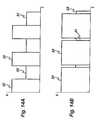
- Figure 14Ashows a first blended output waveform sequence which comprises a constantly alternating combination of a cut waveform 30 and a coag waveform 31.
- the cut waveform 30is limited to a first voltage threshold 32, while the coag waveform 31 is limited to a second (lower) voltage threshold 33.
- the cut waveform 30is supplied for 50% of the duty cycle, and the coag waveform 31 is supplied for the remaining 50% of the duty cycle.
- This output waveform sequenceproduces a tissue effect which simultaneously cuts and coagulates tissue.
- Figure 14Bshows an alternative blended output waveform sequence, again alternating constantly between a cut waveform 30 and a coag waveform 31, each limited to voltage thresholds 32 and 33 respectively.
- the cut waveform 30is supplied for 90% of the duty cycle
- the coag waveform 31is supplied for only 10% of the duty cycle.
- This output waveform sequencecut tissue more effectively than the waveform of Figure 14A , but less of a coagulative effect on the tissue being treated.
- the blended waveforms of Figures 14A and 14Bare two preset settings for the blended output waveform sequence of a generator system according to the present invention, and can be selected or adjusted by the use of a footswitch as shown in Figure 15 , which footswitch is entirely conventional.
- the footswitch 16has two pedals 16A and 16B, the pedal 16A being commonly known as the cut pedal (and typically being coloured yellow), and the pedal 16B being commonly known as the coag pedal (and typically being coloured blue).
- a third pedal 16Cis provided as a mode selection pedal (this pedal typically being of a different shape and size to the other two pedals, and commonly coloured black).
- the cut pedal 16Ais actuated.
- the generatorsupplies a waveform to the instrument in accordance with a predetermined start setting, in this case a 100% coag waveform as shown at "A".
- the waveformchanges according to a predetermined progression, until at "B” the waveform is 50% cut and 50% coag.
- the waveformhas progressed to its end setting as shown at "C", which in this instance is a waveform constituted by 90% cut and 10% coag waveforms. This end setting will be applied to the instrument until the cut pedal 16B is released.
- This progression of the waveform for a start setting to an end settinghas several advantages for the surgeon. Firstly, when using the instrument to cut through thick tissue, bleeding often occurs. This cannot always be compensated for by coagulating thick tissue prior to cutting, as there is the risk that in order to ensure that the entire tissue is coagulated, some of the tissue will become "over-coagulated” and be desiccated. Desiccated tissue is not receptive to RF energy, and so the subsequent cutting of the tissue will not be effective. Thus, bleeding is often associated with the cutting of thick tissue. In the present arrangement, the instrument maintains an element of coagulation, especially at the start of the process. Thus, if the surgeon encounters bleeding during the electrosurgical cut, the surgeon releases and then re-activates the cut pedal 16B. This re-sets the progression to point "A" in Figure 16 , with a high degree of coagulation in the start setting.
- the increasing proportion of the cut waveformensures that the cutting of tissue is effective as soon as it is feasible to occur. Maintaining at least a 10% proportion of the coagulation waveform ensures that coagulation continues to occur as the instrument moves through the tissue.
- the time taken for the generator to progress from the start setting to the end settingmay be varied depending on the type of instrument connected to the generator, and/or the type of tissue typically treated by that instrument.
- the progression timemay be a factory setting, or may be user adjustable using the mode adjustment pedal 16C.
- the progression timeis typically of the order of 7.5 seconds, although progression times of as short as 0.5 seconds or as long as 10 seconds may be used in appropriate circumstances.
- the progression from the start setting to the end settingmay not necessarily be an even progression as shown in Figure 16 .
- the waveformmay remain with a 100% coag content for a predetermined time (say 1.5 seconds) before progressing to the end setting of 90% cut and 10% coag. This is the situation shown in Figure 17 .
- the skilled manwill appreciate that different progressions from the start setting to the end setting will be possible, depending on the type of operation being undertaken.
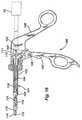
- a bipolar forceps deviceincludes an elongated tubular shaft 101 with a proximal end 102, distal end 103, and a lumen 104 which extends for the entire length of the tubular member.
- a scissors-type handle assembly 105with a first handle 106 and a second handle 107.
- the second handle 107is pivotable with respect to the first, about pivot pin 108.
- the second handle 107has a pin 109 affixed to the top thereof, such that movement of the handle causes a corresponding movement to a sphere 110 supported in a U-shaped cradle 111.
- the jaw assembly 112comprises a first jaw member 113 and a second jaw member 114, pivotally joined to each other by an insulated rivet 115.
- Jaw member 113is provided with a cutting electrode 116, isolated from jaw member 113 by a ceramic insulator 117.
- the rods 118, 119are pivotally connected to the respective jaw members 113, 114 by rigid links 121, whilst rod 120 is connected by means of a wire 124 (as best shown in Fig 22 ) to the electrode 116.
- the proximal ends of the rods 118, 119 and 120extend from the tubular member through the sphere 110 and terminate in a connector 122, by which means the device can be attached to the electrosurgical generator 10.
- the cutting electrode 116is in the form of an elongate rail, extending along the length of the jaw member 113.
- the rail 116is mounted on the ceramic insulator 117 such that it is insulated from the jaw member 113.
- the rail 116is typically 100 microns in width, and protrudes from the ceramic insulator 117 by a distance of approximately 50 microns.
- the jaw assembly 112is in its closed position, the rail 116 is received in a corresponding longitudinal recess 123 in the jaw member 114, best shown in Figure 21 .
- a compressible strip 127 of insulting materialis provided in the recess 123.
- the jaw assembly 112When tissue is to be cut, the jaw assembly 112 is brought adjacent the tissue to be cut, with the jaw assembly in its open position and the tissue positioned in the nip 125 of the jaw assembly.
- a cutting waveform from the electrosurgical generator 10is supplied via the rod 120 to the cutting electrode 116, and the forceps device is moved longitudinally in the direction of the arrow shown in Figure 22 .
- Tissue bridging the cutting electrode 116 and one or both of the jaw members 113 and 114is severed by the electrosurgical waveform as the device is translated longitudinally, thereby forming a longitudinal cut line in the tissue.
- the jaw assemblyis maintained in its open position throughout this process, defining the nip 125 in which the tissue is constrained.
- the devicecan also be used to coagulate tissue, in a more conventional manner, using the jaw assembly in its closed position.
- the jaw assemblyis closed, capturing tissue between the jaw member 113 and the jaw member 114.
- the cutting rail 116is received in the recess 123 and, without the electrosurgical cutting waveform previously described, does not have a cutting effect on the tissue therebetween.
- a coagulating waveform from the electrosurgical generator 10is supplied between the jaw members 113 and 114, via rods 118 and 119. This causes the coagulation of the tissue held between the jaws.
- the devicecan also be used to simultaneously cut and coagulate tissue, using a blended waveform as previously described.
- the jaw assemblyis closed, capturing tissue between the jaw member 113 and the jaw member 114.
- the surgeondepresses the cut pedal 16B on the footswitch 16, and an electrosurgical waveform consisting of the start setting (100% coag) is supplied to the jaw members 113 and 114.
- the waveformprogresses, as previously described, such that an increasing proportion of cut waveform is included, the cut waveform being supplied between the cutting rail 116 and the jaws 113 and 114.
- the waveformreaches its end setting (90% cut and 10% coag), which is continued until the cut pedal 16B is released.
Landscapes
- Health & Medical Sciences (AREA)
- Surgery (AREA)
- Engineering & Computer Science (AREA)
- Life Sciences & Earth Sciences (AREA)
- Biomedical Technology (AREA)
- Molecular Biology (AREA)
- Nuclear Medicine, Radiotherapy & Molecular Imaging (AREA)
- Plasma & Fusion (AREA)
- Physics & Mathematics (AREA)
- Heart & Thoracic Surgery (AREA)
- Medical Informatics (AREA)
- Otolaryngology (AREA)
- Animal Behavior & Ethology (AREA)
- General Health & Medical Sciences (AREA)
- Public Health (AREA)
- Veterinary Medicine (AREA)
- Surgical Instruments (AREA)
- Control Of Eletrric Generators (AREA)
Abstract
Description
- This invention relates to an electrosurgical generator system, and to an electrosurgical system comprising a generator and an electrosurgical instrument with two or more treatment electrodes. Such systems are commonly used for the cutting and/or coagulation of tissue in surgical intervention, most commonly in "keyhole" or minimally invasive surgery, but also in laparoscopic or "open" surgery.
- It is known to provide electrosurgical generators which provide different radio frequency signals for cutting and coagulation, and also to provide a blended signal in which the generator rapidly alternates between the signals for cutting and coagulation. Our
US Patent No. 6,416,509 and alsoUS Patent No. 3,885,569 to Judson describe blended signals of this type.U.S. 2003/163124 (Goble ) discloses an electrosurgical system including an electrosurgical instrument having at least three electrodes. In a combined mode, cutting and coagulating waveforms are delivered either simultaneously or by constantly alternating between first and second output voltage threshold values to form a blended signal. Circuitry causes the cutting waveform to be delivered between a first pair of the electrodes and the coagulating waveform to be delivered between a second pair of electrodes in the blended mode. - According to the present invention, an electrosurgical generator system for generating radio frequency power, comprising:
- (i) a radio frequency output stage having three or more output connections,
- (ii) one or more sources of radio frequency output power coupled to the output stage,
- (iii) a controller operable to cause the system to supply power in a combined mode in which a first cutting RF waveform and a second coagulating RF waveform are delivered to the output connections, the controller including means for feeding the waveforms to the output connections such that the first RF waveform is delivered between a first pair of the output connections, and the second RF waveform is delivered between a second pair of the output connections,
- Our pending European patent application
EP 1287788 describes an electrosurgical system in which the operator can select between a cutting signal and a coagulation signal. When the cutting signal is selected, it is supplied to one pair of electrosurgical electrodes, and when the coagulation signal is selected it is supplied to a different pair of electrosurgical electrodes. Our pending US patent applicationUS2003-0163124 is an improvement to this system, in that it also provides a combined mode of operation, but with the different components of the combined signal being supplied to different sets of electrosurgical electrodes. The present invention provides a further improvement in which the output waveform sequence progresses from a predetermined start setting to a predetermined end setting. - The progression of the waveform sequence offers several advantages to the user. When an electrosurgical instrument is being used to cut tissue, particularly thick tissue, it is difficult to coagulate the tissue completely before cutting commences. If prolonged coagulation is performed before cutting commences, there is the risk that some parts of the tissue will become desiccated. Desiccated tissue is unreceptive to RF energy, and hence a subsequently applied cutting waveform will not be effective. Conversely, if coagulation is incomplete, there is the risk that bleeding will be encountered during cutting. Thus surgeons tend to switch repeatedly between the coagulation and cutting modes of electrosurgical generators as bleeding is encountered (necessitating the repeated operation of the footswitch or the like). The generator described in the present application maintains an element of coagulation throughout the cutting process, with a different proportion of the cutting and coagulation waveforms as the tissue treatment progresses.
- Preferably, the first RF cutting waveform is a waveform in which the radio frequency output voltage developed across the output connections is limited to at least a first predetermined threshold value for cutting or vaporisation of tissue, and the second RF coagulation waveform is a waveform in which the radio frequency output voltage developed across the output connections is limited to a second threshold value for coagulation.
- The "combined mode" of the generator can be provided in different ways. In one arrangement, the generator system comprises a single source of radio frequency power, and, in the combined mode, the controller is operable to cause the generator system to alternate constantly between delivering the first cutting RF waveform and the second coagulating RF waveform. This is the more traditional "blended" signal of
US Patents Nos. 6,416,509 and3,885,569 . Alternatively, the generator system comprises at least first and second sources of radio frequency power, operating at different frequencies, the first source of radio frequency power being adapted to deliver the first cutting RF waveform, and the second source of radio frequency power being adapted to deliver the second coagulating RF waveform, and, in the combined mode, the controller is operable to cause the generator system to deliver both the first and second RF waveforms simultaneously. This is a different arrangement in which the output of two RF sources is supplied to the instrument simultaneously. Both arrangements have the effect, however, of supplying both cutting and coagulating RF signals to the electrosurgical instrument while the instrument is in use. - In a preferred arrangement, the various settings each have a first predetermined duty cycle of the first RF waveform, and a second predetermined duty cycle of the second RF waveform. Preferably, the predetermined start setting has a waveform combination such that the proportion of the second RF waveform is greater than the proportion of the first RF waveform. Additionally, the predetermined end setting has a waveform combination such that the proportion of the first RF waveform is greater than the proportion of the second RF waveform. The start setting conveniently is a waveform having a second duty cycle that is between 70% and 100% of the overall waveform, typically between 90% and 100% of the overall delivered output. Alternatively or additionally, the end setting is a waveform having a first duty cycle that is between 70% and 100% of the overall waveform, typically between 90% and 100% of the overall delivered output. In a typical arrangement, the start setting is a combined waveform having a first duty cycle that is 100% of the overall delivered output, and the end setting is a blended waveform having a second duty cycle that is 90% of the overall delivered output.
- In the above-described arrangement, not only does the generator maintain an element of coagulation throughout the cutting process, but the proportion of the coagulation waveform is greater towards the start of the process. Thus, if the surgeon encounters bleeding during the electrosurgical cut, the surgeon releases and then re-activates the footswitch or other actuating mechanism. This re-sets the progression to the start setting, with a proportionately high degree of coagulation therein.
- Preferably, the predetermined progression from the start setting to the end setting is an even progression over a predetermined time. This ensures that the electrosurgical cutting of the tissue will occur as soon as it is feasible to do so. Alternatively, the progression may not be an even progression; but for example may have an initial period at a constant setting (e.g. a predominantly coagulative waveform), followed by a progression after this initial period to the end setting (e.g. a predominantly cutting waveform). Regardless of whether the progression is an even one, the time taken for the generator to progress from its start setting to its end setting may be varied, depending on the type of instrument connected to the generator, or the type of tissue being treated.
- The controller is preferably adapted to supply an overall output waveform sequence in the form of a series of pulses, conveniently at a frequency of between 0.5 and 50 Hz, and typically at a frequency of between 15 and 25 Hz.
- Described hereinafter is an electrosurgical system including an electrosurgical generator apparatus for generating radio frequency power, and an electrosurgical instrument including at least three electrodes, the generator apparatus comprising
- (i) a radio frequency output stage having at least two output connections in electrical communication with the electrodes of the instrument,
- (ii) a power supply coupled to the output stage for supplying power to the output stage,
- (iii) a controller operable to cause the generator apparatus to supply a blended output waveform alternating constantly between a first output waveform across the output connections in which the radio frequency output voltage developed across the output connections is limited to at least a first predetermined threshold value for cutting or vaporisation of tissue, and a second output waveform across the output connections
- Accordingly, the invention extends to an electrosurgical system comprising
- (i) a bipolar electrosurgical instrument including a handle, a jaw assembly arranged such that manipulation of the handle allows the opposed jaws of the jaw assembly to be opened and closed with respect to one another; a first of said opposed jaws having at least a first coagulating electrode; the other of said opposed jaws having at least a second coagulating electrode; and a cutting electrode the cutting electrode being separated from the second coagulating electrode by an insulating member, and
- (ii) electrosurgical generator apparatus comprising one or more sources of RF output power, a controller operable to control the generator apparatus such that it is capable of providing a first cutting RF waveform to the electrosurgical instrument or a second coagulating RF waveform to the electrosurgical instrument, and, in a combined mode, to deliver both first and second RF waveforms, the waveforms being fed to the electrosurgical instrument such that, in the combined mode, the cutting RF waveform is delivered between the cutting electrode and at least one of the first and second coagulating electrodes, and the coagulating RF waveform is delivered between the first and second coagulating electrodes, the combined mode being adjustable between various settings, each setting having a different proportion of the first and second RF waveforms, the arrangement of the generator apparatus being such that, in response to a operator-actuated input signal, the controller causes the generator apparatus to supply an output waveform sequence starting at a predetermined start setting, ending at a predetermined end setting, and changing between the start and end settings according to a predetermined progression.
- Operation of the preferred system to modify tissue comprises the steps of
- (i) contacting the tissue with the electrosurgical instrument, which includes at least first and second electrodes,
- (ii) supplying to the first and second electrodes an electrosurgical waveform combination including a first proportion comprising an RF cutting waveform and a second proportion comprising an RF coagulating waveform, and
- (iii) varying the first and second waveform proportions according to a predetermined progression.
- The invention will be further described below, by way of example only, with reference to the accompanying drawings. In the drawings:
Figure 1 is a schematic diagram of an electrosurgical system in accordance with the present invention,Figure 2 is a block diagram of the generator ofFigure 1 ,Figure 3 is a schematic perspective view of an electrosurgical instrument used as a part of the system ofFigure 1 ,Figure 4 is a schematic diagram of a switching circuit used in the system ofFigure 1 ,Figures 5A and 5B are circuit diagrams of two electronic switching devices for the switching circuit ofFigure 4 ,Figure 6 is a schematic diagram of an alternative embodiment of switching circuit which can be used in the system ofFigure 1 ,Figure 7 is a block diagram of a generator in accordance withFigure 2 , incorporating a switching circuit in accordance withFigure 4 ,Figures 8A to 8C are diagrams illustrating techniques for adjusting a blend switching ratio,Figures 8A and 8C being circuit diagrams of alternative ratio adjusting devices andFigure 8B being a waveform diagram illustrating the operation of the device ofFigure 8A ,Figure 9 is a block diagram of an alternative embodiment of generator system in accordance with the present invention,Figure 10 is a block diagram of a further alternative system in accordance with the invention,Figures 11A and 11B are yet further alternative systems for feeding cut and coagulation outputs automatically to different respective electrode pairs,Figures 12 and13 are block diagrams of further alternative systems in accordance with the invention,Figures 14A and 14B are waveform diagrams showing different blend waveforms capable of being produced by a generator in accordance with the invention,Figure 15 is a schematic view of a footswitch used as a part of an electrosurgical system in accordance with the present invention,Figures 16 and 17 are diagrams illustrating the adjustment of the generator in accordance with the invention,Figure 18 is a schematic sectional view of an alternative electrosurgical instrument used as part of the system ofFigure 1 ,Figure 19 is a perspective view of the jaw assembly of the instrument ofFigure 18 ,Figure 20 is a cross-sectional view of the body of the instrument ofFigure 18 ,Figure 21 is an end view of the jaw assembly ofFigure 19 , andFigure 22 is a side view of the jaw assembly ofFigure 19 .- Referring to
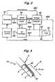
Figure 1 , agenerator 10 has anoutput socket 10S providing a radio frequency (RF) output for aninstrument 12 via aconnection cord 14. Activation of the generator may be performed from theinstrument 12 via a connection incord 14 or by means of afootswitch unit 16, as shown, connected to the rear of the generator by afootswitch connection cord 18. In the illustratedembodiment footswitch unit 16 has twopedals push buttons display 24. Pushbuttons 26 are provided as an alternative means for selection between coagulation and cutting modes. - Referring to
Figure 2 , the generator comprises a radio frequency (RF)power oscillator 60 having a pair ofoutput lines 60C for coupling to theinstrument 12. Theinstrument 12 is shown inFigure 2 in the form of anelectrical load 64. Power is supplied to theoscillator 60 by a switchedmode power supply 66. In the preferred embodiment, theRF oscillator 60 operates at about 400 kHz, with any frequency from 300 kHz upwards into the HF range being feasible. The switched mode power supply typically operates at a frequency in the range of from 25 to 50 kHz. Coupled across theoutput lines 60C is avoltage threshold detector 68 having afirst output 68A coupled to the switchedmode power supply 16 and asecond output 68B coupled to an "on"time control circuit 70. Amicroprocessor controller 72 coupled to the operator controls and display (shown inFigure 1 ) is connected to acontrol input 66A of thepower supply 66 for adjusting the generator output power by supply voltage variation and to a threshold-setinput 68C of thevoltage threshold detector 68 for setting peak RF output voltage limits. - In operation, the
microprocessor controller 72 causes power to be applied to the switchedmode power supply 66 when electrosurgical power is demanded by the surgeon operating an activation switch arrangement which may be provided on a handpiece or footswitch (seeFigure 1 ). A constant output voltage threshold is set independently on the supply voltage viainput 68C according to control settings on the front panel of the generator (seeFigure 1 ). Typically, for desiccation or coagulation the threshold is set at a desiccation threshold value between 150 volts and 200 volts. When a cutting or vaporisation output is required the threshold is set to a value in the range of from 250 or 300 volts to 600 volts. These voltage values are peak values. Their being peak values means that for desiccation at least it is preferable to have an output RF waveform of low crest factor to give maximum power before the voltage is clamped at the values given. Typically a crest factor of 1.5 or less is achieved. When a combined mode output is required, the voltage output set viainput 68C is constantly alternated between the value for desiccation or coagulation and the value for cutting or vaporisation, to form a blended waveform. - When the generator is first activated, the status of the
control input 601 of the RF oscillator 60 (which is connected to the "on" time control circuit 70) is "on", such that the power switching device which forms the oscillating element of theoscillator 60 is switched on for a maximum conduction period during each oscillation cycle. The power delivered to theload 64 depends partly on the supply voltage applied to theRF oscillator 60 from the switchedmode power supply 66 and partly on theload impedance 64. The voltage threshold for a desiccation output is set to cause trigger signals to be sent to the "on"time control circuit 70 and to the switchedmode power supply 66 when the voltage threshold is reached. The "on"time control circuit 70 has the effect of virtually instantaneously reducing the "on" time of the RF oscillator-switching device. Simultaneously, the switched mode power supply is disabled so that the voltage supplied tooscillator 60 begins to fall. The operation of the generator in this way is described in detail in our European Patent Application No.075443 Figure 3 shows one possible design for theelectrosurgical instrument 12. Theinstrument 12 comprises aninstrument shaft 5 at the distal end of which is an electrode assembly shown generally at 8. Theelectrode assembly 8 comprises acentral cutting electrode 2 disposed between twolarger coagulation electrodes layer 4 separates the cuttingelectrode 2 from thefirst coagulating electrode 3, while an insulatinglayer 41 separates the cuttingelectrode 2 from thesecond coagulation electrode 40. The cuttingelectrode 2 protrudes slightly beyond the two coagulating electrodes.- When the user intends the instrument to cut tissue, the generator applies a cutting RF waveform between the cutting
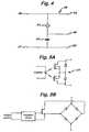
electrode 2 and one or both of the two coagulatingelectrodes electrodes Figure 4 . Figure 4 shows a switching circuit shown generally at 45 and comprisinginput connections output lines 60C of thegenerator 10.Switching circuit 45 has threeoutput connections Output connection 48 is connected to the cuttingelectrode 2 in the device ofFigure 3 .Output connections electrodes Figure 3 . Anelectronic switch device 51 is connected betweenoutput connections switch 51 is capable of rapidly making and breaking the connection between theoutput lines capacitor 53 is connected between theoutput connections - When the user actuates the
pedals instrument 12 in the blended mode, the generator supplies alternating bursts of the RF cutting and coagulating waveforms to theinput connections switch device 51 operates synchronised with the alternating RF waveforms such that when that part of the waveform containing the cutting waveform is received, the switch device is open such that there is open circuit between theoutput connections electrode 2 and coagulatingelectrode 40, viaoutput connections input connections device 51 is closed such thatoutput connections coagulation electrodes output connections capacitor 53 providing a potential difference therebetween. Switching device 51 may comprise an AC opto-relay such as the optically coupled dual FET arrangement shown inFigure 5A . Another switching device providing isolation between control circuitry and the output lines is the combination of an AC bridge and a single MOSFET switch controlled via an isolating driver, a shown inFigure 5B .- The above description is based upon the
generator 10 controlling the blended mode waveform, and theswitching device 51 opening and closing synchronously therewith. However, this does not have to be the case and the switching device can control the generator in order to determine the changeover between the cutting and coagulation RF waveforms. - Consider the switching
circuit 45 as shown inFigure 4 . When theswitching device 51 is in its open condition, the cutting waveform is supplied acrossoutput connections switching device 51 closes, the cutting waveform is initially supplied between theoutput connections capacitor 53. This causes the current delivered by the generator to rise rapidly such that the current limiting circuitry within the generator operates to reduce the power being delivered, such that the waveform rapidly converts to an RF waveform typical for coagulation. The effect of the current limiting circuitry within the generator is that the closing of theswitching device 51 causes the waveform being delivered to be transformed, almost instantaneously, from a cutting waveform to a coagulating waveform. Conversely, when theswitching device 51 opens again, the generator ceases to be current limited, and the waveform once again rapidly reverts to being a cutting RF waveform. In this way, the opening and closing of theswitching device 51 toggles the generator between its cutting and coagulating modes, producing the blended waveform which is supplied to the electrodes of theinstrument 12. Figure 6 shows an alternative embodiment of switching circuit, which can be employed if thegenerator 10 is not a current limited generator, or if it is desired not to use the current limiting features of the generator. The switching circuit ofFigure 6 is almost identical to that ofFigure 4 , the main difference being the addition of anadditional capacitor 52 in series with theinput connection 46. Thecapacitor 52 typically has a value one half of that ofcapacitor 53, such that the voltage delivered acrossoutput connections generator 10. In this way a cutting RF waveform is delivered betweenoutput connections switching device 51 is open, and a coagulating RF waveform is delivered betweenoutput connections Switching circuit 45 can be provided within theelectrosurgical instrument 12, or within the output stage of thegenerator 10 as shown inFigure 7 . Wherever the switchingcircuit 45 is located, the switching device can be provided with an adjustment device 55, (as shown inFigure 6 ) operable by the user of the system in order to adjust the timing of the switching device. By operating the adjustment device 55, the user is able to alter the ratio between that part of the blended RF waveform which is a cutting waveform, and that part which is a coagulating waveform. Whether the adjustment device 55 is located on theinstrument 12 or thegenerator 10, the user of the system can vary the waveform so as to increase or decrease the coagulating component of the blended waveform with respect to the cutting component, and vice versa. This gives considerable flexibility to the electrosurgical system in terms of its use as a simultaneous cutting and coagulation device, with user-operable control of how much coagulation is provided.- As in the arrangement described above in
Figure 4 , the switchingdevice 51 of the alternative switching circuit ofFigure 6 may be as shown inFigure 5A or Figure 5B , the driving signal being obtained from a source associated with the switching device itself or from control circuitry within the generator which controls other generator functions. - Various circuits for implementing the adjustment device 55 will be apparent to those skilled in the art. An example of a circuit in which a blended mode waveform is generated by elements associated with the switching device and has a variable mark-to-space ratio is shown in
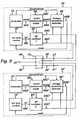
Figure 8A . In this case, the output of atriangular wave generator 56 is compared in acomparator 57 with a user-adjustable reference voltage to produce a square wave of the switching device 51 (Figure 6 ). Another circuit generating an adjustable blended mode switching device control signal is shown inFigure 8C . Here, a user-operable potentiometer 58 is coupled with atimer circuit 59 using a 555 i.c. Figure 9 shows an alternative generator system in which twoRF source circuits 74 and 74' are employed.Source circuit 74 comprisesRF oscillator 60 and its associated power supply and control elements. The source circuit is as described with reference toFigure 2 , and like elements are given the same reference numerals as inFigure 2 . The second source circuit 74' comprises a second RF oscillator 60', along with a second controller 72', power supply 66', voltage threshold detector 68' and on time control circuit 70'.Figure 9 shows the source circuit 74' as having its own dedicated version of each of these units, although it is feasible that certain of them (such as the power supply 66' and controller 72') could be shared with thesource circuit 74. Thevoltage threshold detector 68 is set such that theoutput connections 60C fromsource circuit 74 provide an output power waveform having a cutting RF waveform, while the voltage threshold detector 68' is set such that theoutput connections 60C' from source circuit 74' provide an output power waveform having a coagulating RF waveform. The second oscillator 60' operates at a different frequency from that ofoscillator 60.- A
common output stage 73 is provided for bothsource circuits 74 and 74'.Output connections 60C fromsource circuit 74 are connected to inputconnections output stage 73, whileoutput connections 60C' from source circuit 74' are connected to input connections 46' and 47' of the output stage respectively. Within theoutput stage 73,input connections 47 and 47' are both connected tooutput connection 49, whileinput connection 46 is connected tooutput connection 48, and input connection 46' tooutput connection 50. The result of this arrangement is that the cutting RF waveform fromsource circuit 74 is delivered betweenoutput connections electrosurgical instrument 12. Simultaneously, the coagulating RF waveform from source circuit 74' is delivered betweenoutput connections instrument 12. Thus theelectrosurgical instrument 12 is able simultaneously to cut and coagulate tissue by virtue of the two different frequency waveforms. As before, the advantage is that the cutting waveform and the coagulating waveform, whether they be applied simultaneously or in an alternating blended waveform, are delivered to different pairs of electrodes of the electrosurgical instrument. The design of these electrodes can therefore be optimised, depending on whether they are intended to cut or coagulate tissue. - Referring to
Figure 10 , in an further alternative generator and instrument combination, two RF power oscillators 60-1 and 60-2 are powered from acommon power supply 62 and are controlled by acommon controller 72 to produce onrespective output lines 60C an RF power waveform suitable for cutting and an RF power waveform suitable for coagulation. These waveforms may be fed to aswitching circuit 63 for selecting the power signal from one oscillator 60-1 or the other oscillator 60-2 according to inputs from, for instance, foot switches, the selected power waveform being transmitted onoutput connections connections output connections electrode lines electrode 48 and acommon electrode 49, whereas the coagulation waveform from oscillator 60-2 is fed to acoagulation electrode 50 and thecommon electrode 49. - In the embodiment shown in
Figure 10 , the connection between the electrosurgical generator and the electrosurgical instrument is typically provided byoutput connections - Further embodiments are shown in
Figures 11A and11B . Like the embodiment ofFigure 9 , these embodiments dispense with the need for a signal routing switch or switching circuit. - Referring to
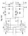
Figure 11 , there are provided two tuned circuits 82-1 and 82-2 (as inFigure 10 ), tuned to different frequencies. Each has a series-resonant inductor-capacitor pair 84 and a parallel-resonant inductor-capacitor pair 86, the latter being transformer coupled tooutput connections Figure 10 , each tuned circuit has two inputs, one of which is connected to agenerator output connection 80 and the other of which is connected to agenerator output connection 81. In this embodiment, the generator has an output stage comprising RF switches arranged in two oppositely acting push-pull pairs switch output connections output connections resonant combinations - The embodiment of
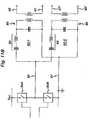
Figure 11B is a modification of that ofFigure 11A , in_which the generator output stage has a single push-pull pair of RF switches 90A, 90B and in which the tuned circuits each have one input connected to the junction between theswitches - A further embodiment of generator circuit is shown in
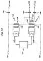
Figure 12 , in which the cut and coag outputs are connected in series across the switching circuitry.Input connections output connections 133 and 134 to the coag electrodes of theelectrosurgical instrument 12.Output connection 135 is connected to the cutting electrode of theelectrosurgical instrument 12. - Between the
input connections first transformer 136 and asecond transformer 137.First transformer 136 comprises primary winding 138 and secondary winding 139. Afirst switch element 140 is provided in parallel with primary winding 138.Second transformer 137 comprises primary winding 141 and secondary winding 142. Asecond switch element 143 is provided in parallel with primary winding 141.Switch elements control unit 144. Thesecondary windings input connections windings - The
second transformer 137 is a step-down transformer in which the secondary winding 142 is itself the primary to a further, a center-tapped, secondary winding 145 connected across theoutput connections 133 and 134. Anisolation capacitor 146 is provided between the bridge circuit and the cuttingoutput connection 135, andfurther isolation capacitors coagulation output connections 133 and 134. - The operation of the circuit is as follows. For a predetermined period,
control unit 144 operatesswitch element 143 to close and short circuit the primary winding 141 of thesecond transformer 137. In this condition, with the transformer secondary 141 effectively short-circuited, the output of the generator is directed between theoutput connection 135 and both of theoutput connections 133 and 134. This has the effect of energizing the cutting electrode of theelectrosurgical instrument 12 with an RF output voltage with respect to the coagulating electrodes thereof, which effectively act as return electrodes for the electrosurgical cutting operation. - At the end of the predetermined period, the
control unit 144 operates to openswitch 143 and thenclose switch 140 to short circuit the primary winding 138 of thefirst transformer 136. There is a short predetermined delay between the opening ofswitch 143 and the closing ofswitch 140 to ensure that both switches are never closed at the same time (as this would short circuit the output connections of the generator). Withswitch 140 closed, thefirst transformer 136 is effectively short-circuited, and the output of the generator is directed entirely to thesecond transformer 137. The second transformer is a step-down transformer, and provides a lower voltage signal between theoutput connections 133 and 134. This has the effect of energizing the first and second coagulating electrodes of theelectrosurgical instrument 12 so as to produce an RF coagulating voltage between them. - After a predetermined time, the
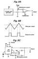
control unit 144 opensswitch 140 and then closesswitch 143, reverting to the condition initially described in which a cutting voltage is delivered to the cutting electrode of theelectrosurgical instrument 12. By constantly alternating between the two conditions herein described, the circuit provides a rapidly alternating cut and coagulation ("coag") waveforms signal to an electrosurgical instrument connected thereto. In this way, the instrument is able to cut tissue as previously described, while simultaneously coagulating the tissue in order to curtail bleeding. Figure 13 shows an alternative embodiment, in which like elements are designated by like reference numerals. Whereas the arrangement ofFigure 12 is particularly suitable for a switching circuit in a unit separate from the generator, the arrangement ofFigure 13 is more suitable for switching circuitry which is integral with the generator. Instead of thesecondary windings Figure 12 , in the arrangement ofFigure 13 the switchingelements primary windings generator 150. InFigure 13 , thesecond transformer 137 is shown as a simple primary winding 141 and secondary winding 145, without the additional isolation provided by the two-stage transformer shown inFigure 12 . The operation of the circuit ofFigure 13 is substantially as described with reference toFigure 12 , with thecontrol unit 144 causingswitches switch 140 is closed, shorting primary winding 138, a coagulating signal is supplied betweenoutput connections 133 and 134. Alternatively, whenswitch 143 is closed, shorting primary winding 141, a cutting signal is supplied between theoutput connection 135 and theconnections 133 and 134.Figure 14A shows a first blended output waveform sequence which comprises a constantly alternating combination of acut waveform 30 and acoag waveform 31. Thecut waveform 30 is limited to afirst voltage threshold 32, while thecoag waveform 31 is limited to a second (lower)voltage threshold 33. Thecut waveform 30 is supplied for 50% of the duty cycle, and thecoag waveform 31 is supplied for the remaining 50% of the duty cycle. This output waveform sequence produces a tissue effect which simultaneously cuts and coagulates tissue.Figure 14B shows an alternative blended output waveform sequence, again alternating constantly between acut waveform 30 and acoag waveform 31, each limited tovoltage thresholds Figure 14B , thecut waveform 30 is supplied for 90% of the duty cycle, and thecoag waveform 31 is supplied for only 10% of the duty cycle. This output waveform sequence cut tissue more effectively than the waveform ofFigure 14A , but less of a coagulative effect on the tissue being treated.- The blended waveforms of
Figures 14A and 14B are two preset settings for the blended output waveform sequence of a generator system according to the present invention, and can be selected or adjusted by the use of a footswitch as shown inFigure 15 , which footswitch is entirely conventional. Thefootswitch 16 has twopedals pedal 16A being commonly known as the cut pedal (and typically being coloured yellow), and the pedal 16B being commonly known as the coag pedal (and typically being coloured blue). Athird pedal 16C is provided as a mode selection pedal (this pedal typically being of a different shape and size to the other two pedals, and commonly coloured black). The operation of the generator system will now be described with reference to these pedals, and to the diagram ofFigure 16 . - If the surgeon is using the electrosurgical instrument connected to the generator merely to coagulate tissue, the actuation of the
coag pedal 16B will cause a 100% coag waveform to be supplied to the instrument. However, when the surgeon wishes to use the instrument to cut tissue, thecut pedal 16A is actuated. When the cut pedal is actuated, the generator supplies a waveform to the instrument in accordance with a predetermined start setting, in this case a 100% coag waveform as shown at "A". As subsequent pulses of energy are supplied to the instrument, the waveform changes according to a predetermined progression, until at "B" the waveform is 50% cut and 50% coag. After time t1 the waveform has progressed to its end setting as shown at "C", which in this instance is a waveform constituted by 90% cut and 10% coag waveforms. This end setting will be applied to the instrument until thecut pedal 16B is released. - This progression of the waveform for a start setting to an end setting has several advantages for the surgeon. Firstly, when using the instrument to cut through thick tissue, bleeding often occurs. This cannot always be compensated for by coagulating thick tissue prior to cutting, as there is the risk that in order to ensure that the entire tissue is coagulated, some of the tissue will become "over-coagulated" and be desiccated. Desiccated tissue is not receptive to RF energy, and so the subsequent cutting of the tissue will not be effective. Thus, bleeding is often associated with the cutting of thick tissue. In the present arrangement, the instrument maintains an element of coagulation, especially at the start of the process. Thus, if the surgeon encounters bleeding during the electrosurgical cut, the surgeon releases and then re-activates the
cut pedal 16B. This re-sets the progression to point "A" inFigure 16 , with a high degree of coagulation in the start setting. - Secondly, the increasing proportion of the cut waveform ensures that the cutting of tissue is effective as soon as it is feasible to occur. Maintaining at least a 10% proportion of the coagulation waveform ensures that coagulation continues to occur as the instrument moves through the tissue.
- The time taken for the generator to progress from the start setting to the end setting may be varied depending on the type of instrument connected to the generator, and/or the type of tissue typically treated by that instrument. The progression time may be a factory setting, or may be user adjustable using the
mode adjustment pedal 16C. The progression time is typically of the order of 7.5 seconds, although progression times of as short as 0.5 seconds or as long as 10 seconds may be used in appropriate circumstances. - The progression from the start setting to the end setting may not necessarily be an even progression as shown in
Figure 16 . For example, the waveform may remain with a 100% coag content for a predetermined time (say 1.5 seconds) before progressing to the end setting of 90% cut and 10% coag. This is the situation shown inFigure 17 . The skilled man will appreciate that different progressions from the start setting to the end setting will be possible, depending on the type of operation being undertaken. Figures 18 to 22 show an alternative type of instrument that can be used in conjunction with the previously described electrosurgical generator. Referring toFigure 18 , a bipolar forceps device includes an elongatedtubular shaft 101 with aproximal end 102,distal end 103, and alumen 104 which extends for the entire length of the tubular member. At theproximal end 102 of thetubular member 101 is a scissors-type handle assembly 105 with afirst handle 106 and asecond handle 107. Thesecond handle 107 is pivotable with respect to the first, aboutpivot pin 108. In a known design of actuation mechanism, thesecond handle 107 has apin 109 affixed to the top thereof, such that movement of the handle causes a corresponding movement to asphere 110 supported in aU-shaped cradle 111.- Fitted into the
distal end 103 of thetubular member 101 is aforceps jaw assembly 112, more particularly shown inFigure 19 . Thejaw assembly 112 comprises afirst jaw member 113 and asecond jaw member 114, pivotally joined to each other by aninsulated rivet 115.Jaw member 113 is provided with a cuttingelectrode 116, isolated fromjaw member 113 by aceramic insulator 117. As shown inFigure 20 , three rigid electricallyconductive rods lumen 104 of thetubular member 101. Therods respective jaw members rigid links 121, whilstrod 120 is connected by means of a wire 124 (as best shown inFig 22 ) to theelectrode 116. The proximal ends of therods sphere 110 and terminate in aconnector 122, by which means the device can be attached to theelectrosurgical generator 10. - As shown in
Figure 19 , the cuttingelectrode 116 is in the form of an elongate rail, extending along the length of thejaw member 113. Therail 116 is mounted on theceramic insulator 117 such that it is insulated from thejaw member 113. Therail 116 is typically 100 microns in width, and protrudes from theceramic insulator 117 by a distance of approximately 50 microns. When thejaw assembly 112 is in its closed position, therail 116 is received in a correspondinglongitudinal recess 123 in thejaw member 114, best shown inFigure 21 . Acompressible strip 127 of insulting material is provided in therecess 123. - The operation of the device will now be further described. When tissue is to be cut, the
jaw assembly 112 is brought adjacent the tissue to be cut, with the jaw assembly in its open position and the tissue positioned in thenip 125 of the jaw assembly. A cutting waveform from theelectrosurgical generator 10 is supplied via therod 120 to the cuttingelectrode 116, and the forceps device is moved longitudinally in the direction of the arrow shown inFigure 22 . Tissue bridging the cuttingelectrode 116 and one or both of thejaw members nip 125 in which the tissue is constrained. - The device can also be used to coagulate tissue, in a more conventional manner, using the jaw assembly in its closed position. The jaw assembly is closed, capturing tissue between the
jaw member 113 and thejaw member 114. The cuttingrail 116 is received in therecess 123 and, without the electrosurgical cutting waveform previously described, does not have a cutting effect on the tissue therebetween. A coagulating waveform from theelectrosurgical generator 10 is supplied between thejaw members rods - The device can also be used to simultaneously cut and coagulate tissue, using a blended waveform as previously described. As before, the jaw assembly is closed, capturing tissue between the
jaw member 113 and thejaw member 114. The surgeon depresses thecut pedal 16B on thefootswitch 16, and an electrosurgical waveform consisting of the start setting (100% coag) is supplied to thejaw members rail 116 and thejaws cut pedal 16B is released.
Claims (16)
- An electrosurgical generator system for generating radio frequency power, comprising:(i) a radio frequency output stage having three or more output connections (48, 49, 50; 133, 134, 135),(ii) one or more sources of radio frequency output power coupled to the output stage,(iii) a controller operable to cause the system to supply power in a combined mode in which a first cutting RF waveform and a second coagulating RF waveform are delivered to the output connections, the controller including means for feeding the waveforms to the output connections such that the first RF waveform is delivered between a first pair of the output connections, and the second RF waveform is delivered between a second pair of the output connections,the arrangement of the system being such that the combined mode is adjustable between various settings, each setting having a different proportion of the first and second RF waveforms,characterized in that, in response to an operator-actuated input signal, the controller causes the system to supply an output waveform sequence starting at a predetermined start setting, ending at a predetermined end setting, and changing between the start and end settings according to a predetermined progression.
- A system according to claim 1, wherein the first RF cutting waveform is a waveform in which the radio frequency output voltage developed across the output connections is limited to at least a first predetermined threshold value for cutting or vaporisation of tissue, and the second RF coagulation waveform is a waveform in which the radio frequency output voltage developed across the output connections is limited to a second threshold value for coagulation.
- A system according to claim 1 or claim 2, wherein the combined mode is provided by the controller operating to supply a blended output waveform sequence alternating constantly between the first RF cutting waveform and the second RF coagulating waveform.
- A system according to claim 3, wherein the various settings each have a first predetermined duty cycle of the first RF waveform, and a second predetermined duty cycle of the second RF waveform.
- A system according to claim 4, wherein the start setting has a second duty cycle that is between 70% and 100% of the overall delivered output.
- A system according to claim 5, wherein the start setting has a second duty cycle that is between 90% and 100% of the overall delivered output.
- A system according to any of claims 4 to 6, wherein the end setting has a first duty cycle that is between 70% and 100% of the overall delivered output.
- A system according to claim 7, wherein the end setting has a first duty cycle that is between 90% and 100% of the overall delivered output.
- A system according to any of claims 4 to 8, wherein the start setting is a waveform having a first duty cycle that is 100% of the overall delivered output, and the end setting is a blended waveform having a second duty cycle that is 90% of the overall delivered output.
- A system according to any preceding claim, wherein the predetermined start setting has a waveform combination such that the proportion of the second RF waveform is greater than the proportion of the first RF waveform.
- A system according to any preceding claim, wherein the predetermined end setting has a waveform combination such that the proportion of the first RF waveform is greater than the proportion of the second RF waveform.
- A system according to any preceding claim, wherein the predetermined progression from the start setting to the end setting is an even progression over a predetermined time.
- A system according to any preceding claim wherein the controller is adapted to supply an overall delivered output waveform sequence in the form of a series of pulses.
- A system according to claim 13, wherein the pulses are provided at a frequency of between 0.5 and 50 Hz.
- A system according to claim 14, wherein the pulses are provided at a frequency of between 15 and 25 Hz.
- An electrosurgical system comprising:(i) a bipolar electrosurgical instrument including a handle (105), a jaw assembly (112) arranged such that manipulation of the handle allows the opposed jaws of the jaw assembly to be opened and closed with respect to one another; a first of said opposed jaws having at least a first coagulating electrode (114); the other of said opposed jaws having at least a second coagulating electrode (113); and a cutting electrode (116), the cutting electrode being separated from the second coagulating electrode by an insulating member (117), and(ii) electrosurgical generator apparatus (10) comprising one or more sources of RF output power, a controller operable to control the generator such that it is capable of providing a first cutting RF waveform to the electrosurgical instrument or a second coagulating RF waveform to the electrosurgical instrument, and, in a combined mode, to deliver both first and second RF waveforms, the waveforms being fed to the electrosurgical instrument such that, in the combined mode, the cutting RF waveform is delivered between the cutting electrode (116) and at least one of the first and second coagulating electrodes (114, 113), and the coagulating RF waveform is delivered between the first and second coagulating electrodes, the combined mode being adjustable between various settings, each setting having a different proportion of the first and second RF waveforms,the arrangement of the generator apparatus system being such that, in response to a operator-actuated input signal, the controller causes the generator apparatus to supply an output waveform sequence starting at a predetermined start setting, ending at a predetermined end setting, and changing between the start and end settings according to a predetermined progression.
Applications Claiming Priority (2)
| Application Number | Priority Date | Filing Date | Title |
|---|---|---|---|
| GB0425051AGB0425051D0 (en) | 2004-11-12 | 2004-11-12 | Electrosurgical generator and system |
| PCT/GB2005/003721WO2006051252A1 (en) | 2004-11-12 | 2005-09-27 | Electrosurgical generator and system |
Publications (2)
| Publication Number | Publication Date |
|---|---|
| EP1814481A1 EP1814481A1 (en) | 2007-08-08 |
| EP1814481B1true EP1814481B1 (en) | 2009-09-09 |
Family
ID=33523656
Family Applications (1)
| Application Number | Title | Priority Date | Filing Date |
|---|---|---|---|
| EP05786860AExpired - LifetimeEP1814481B1 (en) | 2004-11-12 | 2005-09-27 | Electrosurgical generator and system |
Country Status (8)
| Country | Link |
|---|---|
| EP (1) | EP1814481B1 (en) |
| CN (1) | CN100531678C (en) |
| AT (1) | ATE442093T1 (en) |
| AU (1) | AU2005303650B2 (en) |
| DE (1) | DE602005016592D1 (en) |
| ES (1) | ES2333240T3 (en) |
| GB (1) | GB0425051D0 (en) |
| WO (1) | WO2006051252A1 (en) |
Families Citing this family (561)
| Publication number | Priority date | Publication date | Assignee | Title |
|---|---|---|---|---|
| US7282048B2 (en)* | 2001-08-27 | 2007-10-16 | Gyrus Medical Limited | Electrosurgical generator and system |
| US6780178B2 (en) | 2002-05-03 | 2004-08-24 | The Board Of Trustees Of The Leland Stanford Junior University | Method and apparatus for plasma-mediated thermo-electrical ablation |
| US8043286B2 (en) | 2002-05-03 | 2011-10-25 | The Board Of Trustees Of The Leland Stanford Junior University | Method and apparatus for plasma-mediated thermo-electrical ablation |
| US7736361B2 (en) | 2003-02-14 | 2010-06-15 | The Board Of Trustees Of The Leland Stamford Junior University | Electrosurgical system with uniformly enhanced electric field and minimal collateral damage |
| US20070084897A1 (en) | 2003-05-20 | 2007-04-19 | Shelton Frederick E Iv | Articulating surgical stapling instrument incorporating a two-piece e-beam firing mechanism |
| US9060770B2 (en) | 2003-05-20 | 2015-06-23 | Ethicon Endo-Surgery, Inc. | Robotically-driven surgical instrument with E-beam driver |
| US11998198B2 (en) | 2004-07-28 | 2024-06-04 | Cilag Gmbh International | Surgical stapling instrument incorporating a two-piece E-beam firing mechanism |
| US8215531B2 (en) | 2004-07-28 | 2012-07-10 | Ethicon Endo-Surgery, Inc. | Surgical stapling instrument having a medical substance dispenser |
| US11890012B2 (en) | 2004-07-28 | 2024-02-06 | Cilag Gmbh International | Staple cartridge comprising cartridge body and attached support |
| US8905977B2 (en) | 2004-07-28 | 2014-12-09 | Ethicon Endo-Surgery, Inc. | Surgical stapling instrument having an electroactive polymer actuated medical substance dispenser |
| US9072535B2 (en) | 2011-05-27 | 2015-07-07 | Ethicon Endo-Surgery, Inc. | Surgical stapling instruments with rotatable staple deployment arrangements |
| US7669746B2 (en) | 2005-08-31 | 2010-03-02 | Ethicon Endo-Surgery, Inc. | Staple cartridges for forming staples having differing formed staple heights |
| US7673781B2 (en) | 2005-08-31 | 2010-03-09 | Ethicon Endo-Surgery, Inc. | Surgical stapling device with staple driver that supports multiple wire diameter staples |
| US9237891B2 (en) | 2005-08-31 | 2016-01-19 | Ethicon Endo-Surgery, Inc. | Robotically-controlled surgical stapling devices that produce formed staples having different lengths |
| US7934630B2 (en) | 2005-08-31 | 2011-05-03 | Ethicon Endo-Surgery, Inc. | Staple cartridges for forming staples having differing formed staple heights |
| US11484312B2 (en) | 2005-08-31 | 2022-11-01 | Cilag Gmbh International | Staple cartridge comprising a staple driver arrangement |
| US10159482B2 (en) | 2005-08-31 | 2018-12-25 | Ethicon Llc | Fastener cartridge assembly comprising a fixed anvil and different staple heights |
| US11246590B2 (en) | 2005-08-31 | 2022-02-15 | Cilag Gmbh International | Staple cartridge including staple drivers having different unfired heights |
| US8800838B2 (en) | 2005-08-31 | 2014-08-12 | Ethicon Endo-Surgery, Inc. | Robotically-controlled cable-based surgical end effectors |
| US20070106317A1 (en) | 2005-11-09 | 2007-05-10 | Shelton Frederick E Iv | Hydraulically and electrically actuated articulation joints for surgical instruments |
| US8186555B2 (en) | 2006-01-31 | 2012-05-29 | Ethicon Endo-Surgery, Inc. | Motor-driven surgical cutting and fastening instrument with mechanical closure system |
| US20110024477A1 (en) | 2009-02-06 | 2011-02-03 | Hall Steven G | Driven Surgical Stapler Improvements |
| US8820603B2 (en) | 2006-01-31 | 2014-09-02 | Ethicon Endo-Surgery, Inc. | Accessing data stored in a memory of a surgical instrument |
| US8708213B2 (en) | 2006-01-31 | 2014-04-29 | Ethicon Endo-Surgery, Inc. | Surgical instrument having a feedback system |
| US20120292367A1 (en) | 2006-01-31 | 2012-11-22 | Ethicon Endo-Surgery, Inc. | Robotically-controlled end effector |
| US8161977B2 (en) | 2006-01-31 | 2012-04-24 | Ethicon Endo-Surgery, Inc. | Accessing data stored in a memory of a surgical instrument |
| US11278279B2 (en) | 2006-01-31 | 2022-03-22 | Cilag Gmbh International | Surgical instrument assembly |
| US8763879B2 (en) | 2006-01-31 | 2014-07-01 | Ethicon Endo-Surgery, Inc. | Accessing data stored in a memory of surgical instrument |
| US20110295295A1 (en) | 2006-01-31 | 2011-12-01 | Ethicon Endo-Surgery, Inc. | Robotically-controlled surgical instrument having recording capabilities |
| US9861359B2 (en) | 2006-01-31 | 2018-01-09 | Ethicon Llc | Powered surgical instruments with firing system lockout arrangements |
| US11224427B2 (en) | 2006-01-31 | 2022-01-18 | Cilag Gmbh International | Surgical stapling system including a console and retraction assembly |
| US7845537B2 (en) | 2006-01-31 | 2010-12-07 | Ethicon Endo-Surgery, Inc. | Surgical instrument having recording capabilities |
| US7753904B2 (en) | 2006-01-31 | 2010-07-13 | Ethicon Endo-Surgery, Inc. | Endoscopic surgical instrument with a handle that can articulate with respect to the shaft |
| US11793518B2 (en) | 2006-01-31 | 2023-10-24 | Cilag Gmbh International | Powered surgical instruments with firing system lockout arrangements |
| US8236010B2 (en) | 2006-03-23 | 2012-08-07 | Ethicon Endo-Surgery, Inc. | Surgical fastener and cutter with mimicking end effector |
| US8992422B2 (en) | 2006-03-23 | 2015-03-31 | Ethicon Endo-Surgery, Inc. | Robotically-controlled endoscopic accessory channel |
| US8322455B2 (en) | 2006-06-27 | 2012-12-04 | Ethicon Endo-Surgery, Inc. | Manually driven surgical cutting and fastening instrument |
| US7740159B2 (en) | 2006-08-02 | 2010-06-22 | Ethicon Endo-Surgery, Inc. | Pneumatically powered surgical cutting and fastening instrument with a variable control of the actuating rate of firing with mechanical power assist |
| US10130359B2 (en) | 2006-09-29 | 2018-11-20 | Ethicon Llc | Method for forming a staple |
| US10568652B2 (en) | 2006-09-29 | 2020-02-25 | Ethicon Llc | Surgical staples having attached drivers of different heights and stapling instruments for deploying the same |
| US7506791B2 (en) | 2006-09-29 | 2009-03-24 | Ethicon Endo-Surgery, Inc. | Surgical stapling instrument with mechanical mechanism for limiting maximum tissue compression |
| US20110087276A1 (en) | 2009-10-09 | 2011-04-14 | Ethicon Endo-Surgery, Inc. | Method for forming a staple |
| US11980366B2 (en) | 2006-10-03 | 2024-05-14 | Cilag Gmbh International | Surgical instrument |
| JP2010508899A (en) | 2006-11-02 | 2010-03-25 | ピーク サージカル, インコーポレイテッド | Tissue cutting and coagulation with electrical plasma, and surgical devices |
| US8684253B2 (en) | 2007-01-10 | 2014-04-01 | Ethicon Endo-Surgery, Inc. | Surgical instrument with wireless communication between a control unit of a robotic system and remote sensor |
| US11291441B2 (en) | 2007-01-10 | 2022-04-05 | Cilag Gmbh International | Surgical instrument with wireless communication between control unit and remote sensor |
| US8459520B2 (en) | 2007-01-10 | 2013-06-11 | Ethicon Endo-Surgery, Inc. | Surgical instrument with wireless communication between control unit and remote sensor |
| US8632535B2 (en) | 2007-01-10 | 2014-01-21 | Ethicon Endo-Surgery, Inc. | Interlock and surgical instrument including same |
| US8652120B2 (en) | 2007-01-10 | 2014-02-18 | Ethicon Endo-Surgery, Inc. | Surgical instrument with wireless communication between control unit and sensor transponders |
| US20080169333A1 (en) | 2007-01-11 | 2008-07-17 | Shelton Frederick E | Surgical stapler end effector with tapered distal end |
| US11039836B2 (en) | 2007-01-11 | 2021-06-22 | Cilag Gmbh International | Staple cartridge for use with a surgical stapling instrument |
| US7673782B2 (en) | 2007-03-15 | 2010-03-09 | Ethicon Endo-Surgery, Inc. | Surgical stapling instrument having a releasable buttress material |
| US8893946B2 (en) | 2007-03-28 | 2014-11-25 | Ethicon Endo-Surgery, Inc. | Laparoscopic tissue thickness and clamp load measuring devices |
| GB0709994D0 (en) | 2007-05-24 | 2007-07-04 | Gyrus Medical Ltd | Electrosurgical generator |
| US8157145B2 (en) | 2007-05-31 | 2012-04-17 | Ethicon Endo-Surgery, Inc. | Pneumatically powered surgical cutting and fastening instrument with electrical feedback |
| US8931682B2 (en) | 2007-06-04 | 2015-01-13 | Ethicon Endo-Surgery, Inc. | Robotically-controlled shaft based rotary drive systems for surgical instruments |
| US7832408B2 (en) | 2007-06-04 | 2010-11-16 | Ethicon Endo-Surgery, Inc. | Surgical instrument having a directional switching mechanism |
| US8534528B2 (en) | 2007-06-04 | 2013-09-17 | Ethicon Endo-Surgery, Inc. | Surgical instrument having a multiple rate directional switching mechanism |
| US11564682B2 (en) | 2007-06-04 | 2023-01-31 | Cilag Gmbh International | Surgical stapler device |
| US7905380B2 (en) | 2007-06-04 | 2011-03-15 | Ethicon Endo-Surgery, Inc. | Surgical instrument having a multiple rate directional switching mechanism |
| US8408439B2 (en) | 2007-06-22 | 2013-04-02 | Ethicon Endo-Surgery, Inc. | Surgical stapling instrument with an articulatable end effector |
| US7753245B2 (en) | 2007-06-22 | 2010-07-13 | Ethicon Endo-Surgery, Inc. | Surgical stapling instruments |
| US11849941B2 (en) | 2007-06-29 | 2023-12-26 | Cilag Gmbh International | Staple cartridge having staple cavities extending at a transverse angle relative to a longitudinal cartridge axis |
| US7766209B2 (en) | 2008-02-13 | 2010-08-03 | Ethicon Endo-Surgery, Inc. | Surgical stapling instrument with improved firing trigger arrangement |
| US8561870B2 (en) | 2008-02-13 | 2013-10-22 | Ethicon Endo-Surgery, Inc. | Surgical stapling instrument |
| US8540133B2 (en) | 2008-09-19 | 2013-09-24 | Ethicon Endo-Surgery, Inc. | Staple cartridge |
| US8453908B2 (en) | 2008-02-13 | 2013-06-04 | Ethicon Endo-Surgery, Inc. | Surgical stapling instrument with improved firing trigger arrangement |
| US8752749B2 (en) | 2008-02-14 | 2014-06-17 | Ethicon Endo-Surgery, Inc. | Robotically-controlled disposable motor-driven loading unit |
| US11986183B2 (en) | 2008-02-14 | 2024-05-21 | Cilag Gmbh International | Surgical cutting and fastening instrument comprising a plurality of sensors to measure an electrical parameter |
| US8584919B2 (en) | 2008-02-14 | 2013-11-19 | Ethicon Endo-Sugery, Inc. | Surgical stapling apparatus with load-sensitive firing mechanism |
| US7866527B2 (en) | 2008-02-14 | 2011-01-11 | Ethicon Endo-Surgery, Inc. | Surgical stapling apparatus with interlockable firing system |
| US9179912B2 (en) | 2008-02-14 | 2015-11-10 | Ethicon Endo-Surgery, Inc. | Robotically-controlled motorized surgical cutting and fastening instrument |
| US8758391B2 (en) | 2008-02-14 | 2014-06-24 | Ethicon Endo-Surgery, Inc. | Interchangeable tools for surgical instruments |
| US8622274B2 (en) | 2008-02-14 | 2014-01-07 | Ethicon Endo-Surgery, Inc. | Motorized cutting and fastening instrument having control circuit for optimizing battery usage |
| JP5410110B2 (en) | 2008-02-14 | 2014-02-05 | エシコン・エンド−サージェリィ・インコーポレイテッド | Surgical cutting / fixing instrument with RF electrode |
| US7793812B2 (en) | 2008-02-14 | 2010-09-14 | Ethicon Endo-Surgery, Inc. | Disposable motor-driven loading unit for use with a surgical cutting and stapling apparatus |
| US8573465B2 (en) | 2008-02-14 | 2013-11-05 | Ethicon Endo-Surgery, Inc. | Robotically-controlled surgical end effector system with rotary actuated closure systems |
| US8636736B2 (en) | 2008-02-14 | 2014-01-28 | Ethicon Endo-Surgery, Inc. | Motorized surgical cutting and fastening instrument |
| US7819298B2 (en) | 2008-02-14 | 2010-10-26 | Ethicon Endo-Surgery, Inc. | Surgical stapling apparatus with control features operable with one hand |
| US8657174B2 (en) | 2008-02-14 | 2014-02-25 | Ethicon Endo-Surgery, Inc. | Motorized surgical cutting and fastening instrument having handle based power source |
| US8459525B2 (en) | 2008-02-14 | 2013-06-11 | Ethicon Endo-Sugery, Inc. | Motorized surgical cutting and fastening instrument having a magnetic drive train torque limiting device |
| US9585657B2 (en) | 2008-02-15 | 2017-03-07 | Ethicon Endo-Surgery, Llc | Actuator for releasing a layer of material from a surgical end effector |
| US11272927B2 (en) | 2008-02-15 | 2022-03-15 | Cilag Gmbh International | Layer arrangements for surgical staple cartridges |
| US20090206131A1 (en) | 2008-02-15 | 2009-08-20 | Ethicon Endo-Surgery, Inc. | End effector coupling arrangements for a surgical cutting and stapling instrument |
| US20090206141A1 (en) | 2008-02-15 | 2009-08-20 | Ethicon Endo-Surgery, Inc. | Buttress material having an activatable adhesive |
| US8608044B2 (en) | 2008-02-15 | 2013-12-17 | Ethicon Endo-Surgery, Inc. | Feedback and lockout mechanism for surgical instrument |
| US8083120B2 (en) | 2008-09-18 | 2011-12-27 | Ethicon Endo-Surgery, Inc. | End effector for use with a surgical cutting and stapling instrument |
| US7954686B2 (en) | 2008-09-19 | 2011-06-07 | Ethicon Endo-Surgery, Inc. | Surgical stapler with apparatus for adjusting staple height |
| PL3476312T3 (en) | 2008-09-19 | 2024-03-11 | Ethicon Llc | Surgical stapler with apparatus for adjusting staple height |
| US8210411B2 (en) | 2008-09-23 | 2012-07-03 | Ethicon Endo-Surgery, Inc. | Motor-driven surgical cutting instrument |
| US9386983B2 (en) | 2008-09-23 | 2016-07-12 | Ethicon Endo-Surgery, Llc | Robotically-controlled motorized surgical instrument |
| US9005230B2 (en) | 2008-09-23 | 2015-04-14 | Ethicon Endo-Surgery, Inc. | Motorized surgical instrument |
| US11648005B2 (en) | 2008-09-23 | 2023-05-16 | Cilag Gmbh International | Robotically-controlled motorized surgical instrument with an end effector |
| US9050083B2 (en) | 2008-09-23 | 2015-06-09 | Ethicon Endo-Surgery, Inc. | Motorized surgical instrument |
| US8394089B2 (en) | 2008-09-30 | 2013-03-12 | Gyrus Medical Limited | Electrosurgical instrument and system |
| GB0817920D0 (en)* | 2008-09-30 | 2008-11-05 | Gyrus Medical Ltd | Electrosurgical instrument and system |
| US8608045B2 (en) | 2008-10-10 | 2013-12-17 | Ethicon Endo-Sugery, Inc. | Powered surgical cutting and stapling apparatus with manually retractable firing system |
| US8137345B2 (en) | 2009-01-05 | 2012-03-20 | Peak Surgical, Inc. | Electrosurgical devices for tonsillectomy and adenoidectomy |
| US8414577B2 (en) | 2009-02-05 | 2013-04-09 | Ethicon Endo-Surgery, Inc. | Surgical instruments and components for use in sterile environments |
| US8517239B2 (en) | 2009-02-05 | 2013-08-27 | Ethicon Endo-Surgery, Inc. | Surgical stapling instrument comprising a magnetic element driver |
| US8485413B2 (en) | 2009-02-05 | 2013-07-16 | Ethicon Endo-Surgery, Inc. | Surgical stapling instrument comprising an articulation joint |
| US8397971B2 (en) | 2009-02-05 | 2013-03-19 | Ethicon Endo-Surgery, Inc. | Sterilizable surgical instrument |
| WO2010089037A1 (en) | 2009-02-06 | 2010-08-12 | Erbe Elektromedizin Gmbh | Hf surgery device |
| US8453907B2 (en) | 2009-02-06 | 2013-06-04 | Ethicon Endo-Surgery, Inc. | Motor driven surgical fastener device with cutting member reversing mechanism |
| RU2525225C2 (en) | 2009-02-06 | 2014-08-10 | Этикон Эндо-Серджери, Инк. | Improvement of drive surgical suturing instrument |
| US8444036B2 (en) | 2009-02-06 | 2013-05-21 | Ethicon Endo-Surgery, Inc. | Motor driven surgical fastener device with mechanisms for adjusting a tissue gap within the end effector |
| US8066167B2 (en) | 2009-03-23 | 2011-11-29 | Ethicon Endo-Surgery, Inc. | Circular surgical stapling instrument with anvil locking system |
| US20110114697A1 (en) | 2009-11-19 | 2011-05-19 | Ethicon Endo-Surgery, Inc. | Circular stapler introducer with multi-lumen sheath |
| US8136712B2 (en) | 2009-12-10 | 2012-03-20 | Ethicon Endo-Surgery, Inc. | Surgical stapler with discrete staple height adjustment and tactile feedback |
| US8220688B2 (en) | 2009-12-24 | 2012-07-17 | Ethicon Endo-Surgery, Inc. | Motor-driven surgical cutting instrument with electric actuator directional control assembly |
| US8851354B2 (en) | 2009-12-24 | 2014-10-07 | Ethicon Endo-Surgery, Inc. | Surgical cutting instrument that analyzes tissue thickness |
| US8267300B2 (en) | 2009-12-30 | 2012-09-18 | Ethicon Endo-Surgery, Inc. | Dampening device for endoscopic surgical stapler |
| US8608046B2 (en) | 2010-01-07 | 2013-12-17 | Ethicon Endo-Surgery, Inc. | Test device for a surgical tool |
| JP2013524862A (en) | 2010-01-15 | 2013-06-20 | メドトロニック・アドヴァンスド・エナジー・エルエルシー | Electrosurgical apparatus, electrosurgical unit, and method of use thereof |
| DE102010025298B4 (en)* | 2010-06-28 | 2023-06-15 | Celon Ag Medical Instruments | High frequency surgical device |
| US8783543B2 (en) | 2010-07-30 | 2014-07-22 | Ethicon Endo-Surgery, Inc. | Tissue acquisition arrangements and methods for surgical stapling devices |
| US8789740B2 (en) | 2010-07-30 | 2014-07-29 | Ethicon Endo-Surgery, Inc. | Linear cutting and stapling device with selectively disengageable cutting member |
| US8801734B2 (en) | 2010-07-30 | 2014-08-12 | Ethicon Endo-Surgery, Inc. | Circular stapling instruments with secondary cutting arrangements and methods of using same |
| US8360296B2 (en) | 2010-09-09 | 2013-01-29 | Ethicon Endo-Surgery, Inc. | Surgical stapling head assembly with firing lockout for a surgical stapler |
| US9289212B2 (en) | 2010-09-17 | 2016-03-22 | Ethicon Endo-Surgery, Inc. | Surgical instruments and batteries for surgical instruments |
| US8632525B2 (en) | 2010-09-17 | 2014-01-21 | Ethicon Endo-Surgery, Inc. | Power control arrangements for surgical instruments and batteries |
| US20120078244A1 (en) | 2010-09-24 | 2012-03-29 | Worrell Barry C | Control features for articulating surgical device |
| US8733613B2 (en) | 2010-09-29 | 2014-05-27 | Ethicon Endo-Surgery, Inc. | Staple cartridge |
| US11925354B2 (en) | 2010-09-30 | 2024-03-12 | Cilag Gmbh International | Staple cartridge comprising staples positioned within a compressible portion thereof |
| US11812965B2 (en) | 2010-09-30 | 2023-11-14 | Cilag Gmbh International | Layer of material for a surgical end effector |
| US9307989B2 (en) | 2012-03-28 | 2016-04-12 | Ethicon Endo-Surgery, Llc | Tissue stapler having a thickness compensator incorportating a hydrophobic agent |
| US9301752B2 (en) | 2010-09-30 | 2016-04-05 | Ethicon Endo-Surgery, Llc | Tissue thickness compensator comprising a plurality of capsules |
| US9113862B2 (en) | 2010-09-30 | 2015-08-25 | Ethicon Endo-Surgery, Inc. | Surgical stapling instrument with a variable staple forming system |
| US9629814B2 (en) | 2010-09-30 | 2017-04-25 | Ethicon Endo-Surgery, Llc | Tissue thickness compensator configured to redistribute compressive forces |
| US9055941B2 (en) | 2011-09-23 | 2015-06-16 | Ethicon Endo-Surgery, Inc. | Staple cartridge including collapsible deck |
| US9016542B2 (en) | 2010-09-30 | 2015-04-28 | Ethicon Endo-Surgery, Inc. | Staple cartridge comprising compressible distortion resistant components |
| US9364233B2 (en) | 2010-09-30 | 2016-06-14 | Ethicon Endo-Surgery, Llc | Tissue thickness compensators for circular surgical staplers |
| US8893949B2 (en) | 2010-09-30 | 2014-11-25 | Ethicon Endo-Surgery, Inc. | Surgical stapler with floating anvil |
| US11298125B2 (en) | 2010-09-30 | 2022-04-12 | Cilag Gmbh International | Tissue stapler having a thickness compensator |
| US9332974B2 (en) | 2010-09-30 | 2016-05-10 | Ethicon Endo-Surgery, Llc | Layered tissue thickness compensator |
| US9277919B2 (en) | 2010-09-30 | 2016-03-08 | Ethicon Endo-Surgery, Llc | Tissue thickness compensator comprising fibers to produce a resilient load |
| US9301753B2 (en) | 2010-09-30 | 2016-04-05 | Ethicon Endo-Surgery, Llc | Expandable tissue thickness compensator |
| US9220501B2 (en) | 2010-09-30 | 2015-12-29 | Ethicon Endo-Surgery, Inc. | Tissue thickness compensators |
| US12213666B2 (en) | 2010-09-30 | 2025-02-04 | Cilag Gmbh International | Tissue thickness compensator comprising layers |
| US9351730B2 (en) | 2011-04-29 | 2016-05-31 | Ethicon Endo-Surgery, Llc | Tissue thickness compensator comprising channels |
| US10945731B2 (en) | 2010-09-30 | 2021-03-16 | Ethicon Llc | Tissue thickness compensator comprising controlled release and expansion |
| US9232941B2 (en) | 2010-09-30 | 2016-01-12 | Ethicon Endo-Surgery, Inc. | Tissue thickness compensator comprising a reservoir |
| RU2013119928A (en) | 2010-09-30 | 2014-11-10 | Этикон Эндо-Серджери, Инк. | A STAPLING SYSTEM CONTAINING A RETAINING MATRIX AND A LEVELING MATRIX |
| US9386988B2 (en) | 2010-09-30 | 2016-07-12 | Ethicon End-Surgery, LLC | Retainer assembly including a tissue thickness compensator |
| US9788834B2 (en) | 2010-09-30 | 2017-10-17 | Ethicon Llc | Layer comprising deployable attachment members |
| US9314246B2 (en) | 2010-09-30 | 2016-04-19 | Ethicon Endo-Surgery, Llc | Tissue stapler having a thickness compensator incorporating an anti-inflammatory agent |
| USD650074S1 (en) | 2010-10-01 | 2011-12-06 | Ethicon Endo-Surgery, Inc. | Surgical instrument |
| US8695866B2 (en) | 2010-10-01 | 2014-04-15 | Ethicon Endo-Surgery, Inc. | Surgical instrument having a power control circuit |
| US9211122B2 (en) | 2011-03-14 | 2015-12-15 | Ethicon Endo-Surgery, Inc. | Surgical access devices with anvil introduction and specimen retrieval structures |
| US8926598B2 (en) | 2011-03-15 | 2015-01-06 | Ethicon Endo-Surgery, Inc. | Surgical instruments with articulatable and rotatable end effector |
| US9044229B2 (en) | 2011-03-15 | 2015-06-02 | Ethicon Endo-Surgery, Inc. | Surgical fastener instruments |
| US8540131B2 (en) | 2011-03-15 | 2013-09-24 | Ethicon Endo-Surgery, Inc. | Surgical staple cartridges with tissue tethers for manipulating divided tissue and methods of using same |
| US8800841B2 (en) | 2011-03-15 | 2014-08-12 | Ethicon Endo-Surgery, Inc. | Surgical staple cartridges |
| US8857693B2 (en) | 2011-03-15 | 2014-10-14 | Ethicon Endo-Surgery, Inc. | Surgical instruments with lockable articulating end effector |
| GB2489925B (en)* | 2011-04-07 | 2018-09-12 | Gyrus Medical Ltd | Electrosurgical generator |
| AU2012250197B2 (en) | 2011-04-29 | 2017-08-10 | Ethicon Endo-Surgery, Inc. | Staple cartridge comprising staples positioned within a compressible portion thereof |
| US11207064B2 (en) | 2011-05-27 | 2021-12-28 | Cilag Gmbh International | Automated end effector component reloading system for use with a robotic system |
| WO2012170364A1 (en) | 2011-06-10 | 2012-12-13 | Medtronic, Inc. | Wire electrode devices for tonsillectomy and adenoidectomy |
| US8833632B2 (en) | 2011-09-06 | 2014-09-16 | Ethicon Endo-Surgery, Inc. | Firing member displacement system for a stapling instrument |
| US9050084B2 (en) | 2011-09-23 | 2015-06-09 | Ethicon Endo-Surgery, Inc. | Staple cartridge including collapsible deck arrangement |
| US9044230B2 (en) | 2012-02-13 | 2015-06-02 | Ethicon Endo-Surgery, Inc. | Surgical cutting and fastening instrument with apparatus for determining cartridge and firing motion status |
| US9078653B2 (en) | 2012-03-26 | 2015-07-14 | Ethicon Endo-Surgery, Inc. | Surgical stapling device with lockout system for preventing actuation in the absence of an installed staple cartridge |
| MX358135B (en) | 2012-03-28 | 2018-08-06 | Ethicon Endo Surgery Inc | Tissue thickness compensator comprising a plurality of layers. |
| BR112014024098B1 (en) | 2012-03-28 | 2021-05-25 | Ethicon Endo-Surgery, Inc. | staple cartridge |
| US9198662B2 (en) | 2012-03-28 | 2015-12-01 | Ethicon Endo-Surgery, Inc. | Tissue thickness compensator having improved visibility |
| JP6224070B2 (en) | 2012-03-28 | 2017-11-01 | エシコン・エンド−サージェリィ・インコーポレイテッドEthicon Endo−Surgery,Inc. | Retainer assembly including tissue thickness compensator |
| US9101358B2 (en) | 2012-06-15 | 2015-08-11 | Ethicon Endo-Surgery, Inc. | Articulatable surgical instrument comprising a firing drive |
| US20140005718A1 (en) | 2012-06-28 | 2014-01-02 | Ethicon Endo-Surgery, Inc. | Multi-functional powered surgical device with external dissection features |
| US9072536B2 (en) | 2012-06-28 | 2015-07-07 | Ethicon Endo-Surgery, Inc. | Differential locking arrangements for rotary powered surgical instruments |
| US9125662B2 (en) | 2012-06-28 | 2015-09-08 | Ethicon Endo-Surgery, Inc. | Multi-axis articulating and rotating surgical tools |
| US9282974B2 (en) | 2012-06-28 | 2016-03-15 | Ethicon Endo-Surgery, Llc | Empty clip cartridge lockout |
| US8747238B2 (en) | 2012-06-28 | 2014-06-10 | Ethicon Endo-Surgery, Inc. | Rotary drive shaft assemblies for surgical instruments with articulatable end effectors |
| US9028494B2 (en) | 2012-06-28 | 2015-05-12 | Ethicon Endo-Surgery, Inc. | Interchangeable end effector coupling arrangement |
| US20140001231A1 (en) | 2012-06-28 | 2014-01-02 | Ethicon Endo-Surgery, Inc. | Firing system lockout arrangements for surgical instruments |
| US12383267B2 (en) | 2012-06-28 | 2025-08-12 | Cilag Gmbh International | Robotically powered surgical device with manually-actuatable reversing system |
| US9289256B2 (en) | 2012-06-28 | 2016-03-22 | Ethicon Endo-Surgery, Llc | Surgical end effectors having angled tissue-contacting surfaces |
| US11278284B2 (en) | 2012-06-28 | 2022-03-22 | Cilag Gmbh International | Rotary drive arrangements for surgical instruments |
| US9119657B2 (en) | 2012-06-28 | 2015-09-01 | Ethicon Endo-Surgery, Inc. | Rotary actuatable closure arrangement for surgical end effector |
| US9561038B2 (en) | 2012-06-28 | 2017-02-07 | Ethicon Endo-Surgery, Llc | Interchangeable clip applier |
| US9101385B2 (en) | 2012-06-28 | 2015-08-11 | Ethicon Endo-Surgery, Inc. | Electrode connections for rotary driven surgical tools |
| JP6290201B2 (en) | 2012-06-28 | 2018-03-07 | エシコン・エンド−サージェリィ・インコーポレイテッドEthicon Endo−Surgery,Inc. | Lockout for empty clip cartridge |
| BR112014032776B1 (en) | 2012-06-28 | 2021-09-08 | Ethicon Endo-Surgery, Inc | SURGICAL INSTRUMENT SYSTEM AND SURGICAL KIT FOR USE WITH A SURGICAL INSTRUMENT SYSTEM |
| US9408606B2 (en) | 2012-06-28 | 2016-08-09 | Ethicon Endo-Surgery, Llc | Robotically powered surgical device with manually-actuatable reversing system |
| US9386985B2 (en) | 2012-10-15 | 2016-07-12 | Ethicon Endo-Surgery, Llc | Surgical cutting instrument |
| US9386984B2 (en) | 2013-02-08 | 2016-07-12 | Ethicon Endo-Surgery, Llc | Staple cartridge comprising a releasable cover |
| US10092292B2 (en) | 2013-02-28 | 2018-10-09 | Ethicon Llc | Staple forming features for surgical stapling instrument |
| RU2672520C2 (en) | 2013-03-01 | 2018-11-15 | Этикон Эндо-Серджери, Инк. | Hingedly turnable surgical instruments with conducting ways for signal transfer |
| BR112015021082B1 (en) | 2013-03-01 | 2022-05-10 | Ethicon Endo-Surgery, Inc | surgical instrument |
| US9468438B2 (en) | 2013-03-01 | 2016-10-18 | Eticon Endo-Surgery, LLC | Sensor straightened end effector during removal through trocar |
| US9345481B2 (en) | 2013-03-13 | 2016-05-24 | Ethicon Endo-Surgery, Llc | Staple cartridge tissue thickness sensor system |
| US9629629B2 (en) | 2013-03-14 | 2017-04-25 | Ethicon Endo-Surgey, LLC | Control systems for surgical instruments |
| US9808244B2 (en) | 2013-03-14 | 2017-11-07 | Ethicon Llc | Sensor arrangements for absolute positioning system for surgical instruments |
| US9795384B2 (en) | 2013-03-27 | 2017-10-24 | Ethicon Llc | Fastener cartridge comprising a tissue thickness compensator and a gap setting element |
| US9572577B2 (en) | 2013-03-27 | 2017-02-21 | Ethicon Endo-Surgery, Llc | Fastener cartridge comprising a tissue thickness compensator including openings therein |
| US9332984B2 (en) | 2013-03-27 | 2016-05-10 | Ethicon Endo-Surgery, Llc | Fastener cartridge assemblies |
| US9826976B2 (en) | 2013-04-16 | 2017-11-28 | Ethicon Llc | Motor driven surgical instruments with lockable dual drive shafts |
| BR112015026109B1 (en) | 2013-04-16 | 2022-02-22 | Ethicon Endo-Surgery, Inc | surgical instrument |
| US9574644B2 (en) | 2013-05-30 | 2017-02-21 | Ethicon Endo-Surgery, Llc | Power module for use with a surgical instrument |
| US9775609B2 (en) | 2013-08-23 | 2017-10-03 | Ethicon Llc | Tamper proof circuit for surgical instrument battery pack |
| MX369362B (en) | 2013-08-23 | 2019-11-06 | Ethicon Endo Surgery Llc | Firing member retraction devices for powered surgical instruments. |
| US20140171986A1 (en) | 2013-09-13 | 2014-06-19 | Ethicon Endo-Surgery, Inc. | Surgical Clip Having Comliant Portion |
| US20150173749A1 (en) | 2013-12-23 | 2015-06-25 | Ethicon Endo-Surgery, Inc. | Surgical staples and staple cartridges |
| US9642620B2 (en) | 2013-12-23 | 2017-05-09 | Ethicon Endo-Surgery, Llc | Surgical cutting and stapling instruments with articulatable end effectors |
| US9839428B2 (en) | 2013-12-23 | 2017-12-12 | Ethicon Llc | Surgical cutting and stapling instruments with independent jaw control features |
| US9681870B2 (en) | 2013-12-23 | 2017-06-20 | Ethicon Llc | Articulatable surgical instruments with separate and distinct closing and firing systems |
| US20150173756A1 (en) | 2013-12-23 | 2015-06-25 | Ethicon Endo-Surgery, Inc. | Surgical cutting and stapling methods |
| US9724092B2 (en) | 2013-12-23 | 2017-08-08 | Ethicon Llc | Modular surgical instruments |
| US9962161B2 (en) | 2014-02-12 | 2018-05-08 | Ethicon Llc | Deliverable surgical instrument |
| JP6462004B2 (en) | 2014-02-24 | 2019-01-30 | エシコン エルエルシー | Fastening system with launcher lockout |
| US20140166724A1 (en) | 2014-02-24 | 2014-06-19 | Ethicon Endo-Surgery, Inc. | Staple cartridge including a barbed staple |
| US10013049B2 (en) | 2014-03-26 | 2018-07-03 | Ethicon Llc | Power management through sleep options of segmented circuit and wake up control |
| BR112016021943B1 (en) | 2014-03-26 | 2022-06-14 | Ethicon Endo-Surgery, Llc | SURGICAL INSTRUMENT FOR USE BY AN OPERATOR IN A SURGICAL PROCEDURE |
| US10004497B2 (en) | 2014-03-26 | 2018-06-26 | Ethicon Llc | Interface systems for use with surgical instruments |
| US9913642B2 (en) | 2014-03-26 | 2018-03-13 | Ethicon Llc | Surgical instrument comprising a sensor system |
| US12232723B2 (en) | 2014-03-26 | 2025-02-25 | Cilag Gmbh International | Systems and methods for controlling a segmented circuit |
| US20150272580A1 (en) | 2014-03-26 | 2015-10-01 | Ethicon Endo-Surgery, Inc. | Verification of number of battery exchanges/procedure count |
| US10470768B2 (en) | 2014-04-16 | 2019-11-12 | Ethicon Llc | Fastener cartridge including a layer attached thereto |
| CN106456159B (en) | 2014-04-16 | 2019-03-08 | 伊西康内外科有限责任公司 | Fastener Cartridge Assembly and Nail Retainer Cover Arrangement |
| US20150297225A1 (en) | 2014-04-16 | 2015-10-22 | Ethicon Endo-Surgery, Inc. | Fastener cartridges including extensions having different configurations |
| US10327764B2 (en) | 2014-09-26 | 2019-06-25 | Ethicon Llc | Method for creating a flexible staple line |
| BR112016023825B1 (en) | 2014-04-16 | 2022-08-02 | Ethicon Endo-Surgery, Llc | STAPLE CARTRIDGE FOR USE WITH A SURGICAL STAPLER AND STAPLE CARTRIDGE FOR USE WITH A SURGICAL INSTRUMENT |
| CN106456176B (en) | 2014-04-16 | 2019-06-28 | 伊西康内外科有限责任公司 | Fastener Cartridge Including Extensions With Different Configurations |
| US10045781B2 (en) | 2014-06-13 | 2018-08-14 | Ethicon Llc | Closure lockout systems for surgical instruments |
| US11311294B2 (en) | 2014-09-05 | 2022-04-26 | Cilag Gmbh International | Powered medical device including measurement of closure state of jaws |
| BR112017004361B1 (en) | 2014-09-05 | 2023-04-11 | Ethicon Llc | ELECTRONIC SYSTEM FOR A SURGICAL INSTRUMENT |
| US10135242B2 (en) | 2014-09-05 | 2018-11-20 | Ethicon Llc | Smart cartridge wake up operation and data retention |
| US10105142B2 (en) | 2014-09-18 | 2018-10-23 | Ethicon Llc | Surgical stapler with plurality of cutting elements |
| US11523821B2 (en) | 2014-09-26 | 2022-12-13 | Cilag Gmbh International | Method for creating a flexible staple line |
| CN107427300B (en) | 2014-09-26 | 2020-12-04 | 伊西康有限责任公司 | Surgical suture buttresses and auxiliary materials |
| US10076325B2 (en) | 2014-10-13 | 2018-09-18 | Ethicon Llc | Surgical stapling apparatus comprising a tissue stop |
| US9924944B2 (en) | 2014-10-16 | 2018-03-27 | Ethicon Llc | Staple cartridge comprising an adjunct material |
| US11141153B2 (en) | 2014-10-29 | 2021-10-12 | Cilag Gmbh International | Staple cartridges comprising driver arrangements |
| US10517594B2 (en) | 2014-10-29 | 2019-12-31 | Ethicon Llc | Cartridge assemblies for surgical staplers |
| US9844376B2 (en) | 2014-11-06 | 2017-12-19 | Ethicon Llc | Staple cartridge comprising a releasable adjunct material |
| US10736636B2 (en) | 2014-12-10 | 2020-08-11 | Ethicon Llc | Articulatable surgical instrument system |
| US10085748B2 (en) | 2014-12-18 | 2018-10-02 | Ethicon Llc | Locking arrangements for detachable shaft assemblies with articulatable surgical end effectors |
| US9844374B2 (en) | 2014-12-18 | 2017-12-19 | Ethicon Llc | Surgical instrument systems comprising an articulatable end effector and means for adjusting the firing stroke of a firing member |
| US10188385B2 (en) | 2014-12-18 | 2019-01-29 | Ethicon Llc | Surgical instrument system comprising lockable systems |
| MX389118B (en) | 2014-12-18 | 2025-03-20 | Ethicon Llc | SURGICAL INSTRUMENT WITH AN ANVIL THAT CAN BE SELECTIVELY MOVED ON A DISCRETE, NON-MOBILE AXIS RELATIVE TO A STAPLE CARTRIDGE. |
| US10117649B2 (en) | 2014-12-18 | 2018-11-06 | Ethicon Llc | Surgical instrument assembly comprising a lockable articulation system |
| US9844375B2 (en) | 2014-12-18 | 2017-12-19 | Ethicon Llc | Drive arrangements for articulatable surgical instruments |
| US9943309B2 (en) | 2014-12-18 | 2018-04-17 | Ethicon Llc | Surgical instruments with articulatable end effectors and movable firing beam support arrangements |
| US9987000B2 (en) | 2014-12-18 | 2018-06-05 | Ethicon Llc | Surgical instrument assembly comprising a flexible articulation system |
| US10180463B2 (en) | 2015-02-27 | 2019-01-15 | Ethicon Llc | Surgical apparatus configured to assess whether a performance parameter of the surgical apparatus is within an acceptable performance band |
| US11154301B2 (en) | 2015-02-27 | 2021-10-26 | Cilag Gmbh International | Modular stapling assembly |
| US10159483B2 (en) | 2015-02-27 | 2018-12-25 | Ethicon Llc | Surgical apparatus configured to track an end-of-life parameter |
| US9993258B2 (en) | 2015-02-27 | 2018-06-12 | Ethicon Llc | Adaptable surgical instrument handle |
| US10441279B2 (en) | 2015-03-06 | 2019-10-15 | Ethicon Llc | Multiple level thresholds to modify operation of powered surgical instruments |
| US10045776B2 (en) | 2015-03-06 | 2018-08-14 | Ethicon Llc | Control techniques and sub-processor contained within modular shaft with select control processing from handle |
| US9993248B2 (en) | 2015-03-06 | 2018-06-12 | Ethicon Endo-Surgery, Llc | Smart sensors with local signal processing |
| US10548504B2 (en) | 2015-03-06 | 2020-02-04 | Ethicon Llc | Overlaid multi sensor radio frequency (RF) electrode system to measure tissue compression |
| JP2020121162A (en) | 2015-03-06 | 2020-08-13 | エシコン エルエルシーEthicon LLC | Time dependent evaluation of sensor data to determine stability element, creep element and viscoelastic element of measurement |
| US9895148B2 (en) | 2015-03-06 | 2018-02-20 | Ethicon Endo-Surgery, Llc | Monitoring speed control and precision incrementing of motor for powered surgical instruments |
| US9924961B2 (en) | 2015-03-06 | 2018-03-27 | Ethicon Endo-Surgery, Llc | Interactive feedback system for powered surgical instruments |
| US10245033B2 (en) | 2015-03-06 | 2019-04-02 | Ethicon Llc | Surgical instrument comprising a lockable battery housing |
| US10687806B2 (en) | 2015-03-06 | 2020-06-23 | Ethicon Llc | Adaptive tissue compression techniques to adjust closure rates for multiple tissue types |
| US9901342B2 (en) | 2015-03-06 | 2018-02-27 | Ethicon Endo-Surgery, Llc | Signal and power communication system positioned on a rotatable shaft |
| US9808246B2 (en) | 2015-03-06 | 2017-11-07 | Ethicon Endo-Surgery, Llc | Method of operating a powered surgical instrument |
| US10617412B2 (en) | 2015-03-06 | 2020-04-14 | Ethicon Llc | System for detecting the mis-insertion of a staple cartridge into a surgical stapler |
| US10433844B2 (en) | 2015-03-31 | 2019-10-08 | Ethicon Llc | Surgical instrument with selectively disengageable threaded drive systems |
| US10154841B2 (en) | 2015-06-18 | 2018-12-18 | Ethicon Llc | Surgical stapling instruments with lockout arrangements for preventing firing system actuation when a cartridge is spent or missing |
| US10835249B2 (en) | 2015-08-17 | 2020-11-17 | Ethicon Llc | Implantable layers for a surgical instrument |
| MX2022009705A (en) | 2015-08-26 | 2022-11-07 | Ethicon Llc | Surgical staples comprising hardness variations for improved fastening of tissue. |
| US10980538B2 (en) | 2015-08-26 | 2021-04-20 | Ethicon Llc | Surgical stapling configurations for curved and circular stapling instruments |
| RU2725081C2 (en) | 2015-08-26 | 2020-06-29 | ЭТИКОН ЭлЭлСи | Strips with surgical staples allowing the presence of staples with variable properties and providing simple loading of the cartridge |
| MX2018002392A (en) | 2015-08-26 | 2018-08-01 | Ethicon Llc | Staple cartridge assembly comprising various tissue compression gaps and staple forming gaps. |
| MX2022006189A (en) | 2015-09-02 | 2022-06-16 | Ethicon Llc | Surgical staple configurations with camming surfaces located between portions supporting surgical staples. |
| US10238390B2 (en) | 2015-09-02 | 2019-03-26 | Ethicon Llc | Surgical staple cartridges with driver arrangements for establishing herringbone staple patterns |
| US10238386B2 (en) | 2015-09-23 | 2019-03-26 | Ethicon Llc | Surgical stapler having motor control based on an electrical parameter related to a motor current |
| US10085751B2 (en) | 2015-09-23 | 2018-10-02 | Ethicon Llc | Surgical stapler having temperature-based motor control |
| US10363036B2 (en) | 2015-09-23 | 2019-07-30 | Ethicon Llc | Surgical stapler having force-based motor control |
| US10076326B2 (en) | 2015-09-23 | 2018-09-18 | Ethicon Llc | Surgical stapler having current mirror-based motor control |
| US10105139B2 (en) | 2015-09-23 | 2018-10-23 | Ethicon Llc | Surgical stapler having downstream current-based motor control |
| US10327769B2 (en) | 2015-09-23 | 2019-06-25 | Ethicon Llc | Surgical stapler having motor control based on a drive system component |
| US10299878B2 (en) | 2015-09-25 | 2019-05-28 | Ethicon Llc | Implantable adjunct systems for determining adjunct skew |
| US10433846B2 (en) | 2015-09-30 | 2019-10-08 | Ethicon Llc | Compressible adjunct with crossing spacer fibers |
| US10478188B2 (en) | 2015-09-30 | 2019-11-19 | Ethicon Llc | Implantable layer comprising a constricted configuration |
| US11890015B2 (en) | 2015-09-30 | 2024-02-06 | Cilag Gmbh International | Compressible adjunct with crossing spacer fibers |
| US10980539B2 (en) | 2015-09-30 | 2021-04-20 | Ethicon Llc | Implantable adjunct comprising bonded layers |
| US10368865B2 (en) | 2015-12-30 | 2019-08-06 | Ethicon Llc | Mechanisms for compensating for drivetrain failure in powered surgical instruments |
| US10265068B2 (en) | 2015-12-30 | 2019-04-23 | Ethicon Llc | Surgical instruments with separable motors and motor control circuits |
| US10292704B2 (en) | 2015-12-30 | 2019-05-21 | Ethicon Llc | Mechanisms for compensating for battery pack failure in powered surgical instruments |
| US11213293B2 (en) | 2016-02-09 | 2022-01-04 | Cilag Gmbh International | Articulatable surgical instruments with single articulation link arrangements |
| BR112018016098B1 (en) | 2016-02-09 | 2023-02-23 | Ethicon Llc | SURGICAL INSTRUMENT |
| US10413291B2 (en) | 2016-02-09 | 2019-09-17 | Ethicon Llc | Surgical instrument articulation mechanism with slotted secondary constraint |
| US10258331B2 (en) | 2016-02-12 | 2019-04-16 | Ethicon Llc | Mechanisms for compensating for drivetrain failure in powered surgical instruments |
| US10448948B2 (en) | 2016-02-12 | 2019-10-22 | Ethicon Llc | Mechanisms for compensating for drivetrain failure in powered surgical instruments |
| US11224426B2 (en) | 2016-02-12 | 2022-01-18 | Cilag Gmbh International | Mechanisms for compensating for drivetrain failure in powered surgical instruments |
| US10531874B2 (en) | 2016-04-01 | 2020-01-14 | Ethicon Llc | Surgical cutting and stapling end effector with anvil concentric drive member |
| US10420552B2 (en) | 2016-04-01 | 2019-09-24 | Ethicon Llc | Surgical stapling system configured to provide selective cutting of tissue |
| US10413297B2 (en) | 2016-04-01 | 2019-09-17 | Ethicon Llc | Surgical stapling system configured to apply annular rows of staples having different heights |
| US10617413B2 (en) | 2016-04-01 | 2020-04-14 | Ethicon Llc | Closure system arrangements for surgical cutting and stapling devices with separate and distinct firing shafts |
| US11284890B2 (en) | 2016-04-01 | 2022-03-29 | Cilag Gmbh International | Circular stapling system comprising an incisable tissue support |
| JP7010838B2 (en) | 2016-04-01 | 2022-01-26 | エシコン エルエルシー | Surgical staple fasteners |
| US10492783B2 (en) | 2016-04-15 | 2019-12-03 | Ethicon, Llc | Surgical instrument with improved stop/start control during a firing motion |
| US10357247B2 (en) | 2016-04-15 | 2019-07-23 | Ethicon Llc | Surgical instrument with multiple program responses during a firing motion |
| US10828028B2 (en) | 2016-04-15 | 2020-11-10 | Ethicon Llc | Surgical instrument with multiple program responses during a firing motion |
| US10456137B2 (en) | 2016-04-15 | 2019-10-29 | Ethicon Llc | Staple formation detection mechanisms |
| US10335145B2 (en) | 2016-04-15 | 2019-07-02 | Ethicon Llc | Modular surgical instrument with configurable operating mode |
| US11607239B2 (en) | 2016-04-15 | 2023-03-21 | Cilag Gmbh International | Systems and methods for controlling a surgical stapling and cutting instrument |
| US10426467B2 (en) | 2016-04-15 | 2019-10-01 | Ethicon Llc | Surgical instrument with detection sensors |
| US10405859B2 (en) | 2016-04-15 | 2019-09-10 | Ethicon Llc | Surgical instrument with adjustable stop/start control during a firing motion |
| US11179150B2 (en) | 2016-04-15 | 2021-11-23 | Cilag Gmbh International | Systems and methods for controlling a surgical stapling and cutting instrument |
| US20170296173A1 (en) | 2016-04-18 | 2017-10-19 | Ethicon Endo-Surgery, Llc | Method for operating a surgical instrument |
| US10363037B2 (en) | 2016-04-18 | 2019-07-30 | Ethicon Llc | Surgical instrument system comprising a magnetic lockout |
| US11317917B2 (en) | 2016-04-18 | 2022-05-03 | Cilag Gmbh International | Surgical stapling system comprising a lockable firing assembly |
| JP6957532B2 (en) | 2016-06-24 | 2021-11-02 | エシコン エルエルシーEthicon LLC | Staple cartridges including wire staples and punched staples |
| USD850617S1 (en) | 2016-06-24 | 2019-06-04 | Ethicon Llc | Surgical fastener cartridge |
| JP6980705B2 (en) | 2016-06-24 | 2021-12-15 | エシコン エルエルシーEthicon LLC | Stapling system for use with wire staples and punched staples |
| US10893863B2 (en) | 2016-06-24 | 2021-01-19 | Ethicon Llc | Staple cartridge comprising offset longitudinal staple rows |
| USD847989S1 (en) | 2016-06-24 | 2019-05-07 | Ethicon Llc | Surgical fastener cartridge |
| USD826405S1 (en) | 2016-06-24 | 2018-08-21 | Ethicon Llc | Surgical fastener |
| US10500000B2 (en) | 2016-08-16 | 2019-12-10 | Ethicon Llc | Surgical tool with manual control of end effector jaws |
| US10568625B2 (en) | 2016-12-21 | 2020-02-25 | Ethicon Llc | Staple cartridges and arrangements of staples and staple cavities therein |
| US11419606B2 (en) | 2016-12-21 | 2022-08-23 | Cilag Gmbh International | Shaft assembly comprising a clutch configured to adapt the output of a rotary firing member to two different systems |
| US10898186B2 (en) | 2016-12-21 | 2021-01-26 | Ethicon Llc | Staple forming pocket arrangements comprising primary sidewalls and pocket sidewalls |
| JP2020501815A (en) | 2016-12-21 | 2020-01-23 | エシコン エルエルシーEthicon LLC | Surgical stapling system |
| US10758229B2 (en) | 2016-12-21 | 2020-09-01 | Ethicon Llc | Surgical instrument comprising improved jaw control |
| US10695055B2 (en) | 2016-12-21 | 2020-06-30 | Ethicon Llc | Firing assembly comprising a lockout |
| US20180168615A1 (en) | 2016-12-21 | 2018-06-21 | Ethicon Endo-Surgery, Llc | Method of deforming staples from two different types of staple cartridges with the same surgical stapling instrument |
| US10993715B2 (en) | 2016-12-21 | 2021-05-04 | Ethicon Llc | Staple cartridge comprising staples with different clamping breadths |
| US10687810B2 (en) | 2016-12-21 | 2020-06-23 | Ethicon Llc | Stepped staple cartridge with tissue retention and gap setting features |
| MX2019007295A (en) | 2016-12-21 | 2019-10-15 | Ethicon Llc | Surgical instrument system comprising an end effector lockout and a firing assembly lockout. |
| US10426471B2 (en) | 2016-12-21 | 2019-10-01 | Ethicon Llc | Surgical instrument with multiple failure response modes |
| US10973516B2 (en) | 2016-12-21 | 2021-04-13 | Ethicon Llc | Surgical end effectors and adaptable firing members therefor |
| JP7010956B2 (en) | 2016-12-21 | 2022-01-26 | エシコン エルエルシー | How to staple tissue |
| US10582928B2 (en) | 2016-12-21 | 2020-03-10 | Ethicon Llc | Articulation lock arrangements for locking an end effector in an articulated position in response to actuation of a jaw closure system |
| US10813638B2 (en) | 2016-12-21 | 2020-10-27 | Ethicon Llc | Surgical end effectors with expandable tissue stop arrangements |
| US10485543B2 (en) | 2016-12-21 | 2019-11-26 | Ethicon Llc | Anvil having a knife slot width |
| US11090048B2 (en) | 2016-12-21 | 2021-08-17 | Cilag Gmbh International | Method for resetting a fuse of a surgical instrument shaft |
| JP6983893B2 (en) | 2016-12-21 | 2021-12-17 | エシコン エルエルシーEthicon LLC | Lockout configuration for surgical end effectors and replaceable tool assemblies |
| US11134942B2 (en) | 2016-12-21 | 2021-10-05 | Cilag Gmbh International | Surgical stapling instruments and staple-forming anvils |
| JP7010957B2 (en) | 2016-12-21 | 2022-01-26 | エシコン エルエルシー | Shaft assembly with lockout |
| US10542982B2 (en) | 2016-12-21 | 2020-01-28 | Ethicon Llc | Shaft assembly comprising first and second articulation lockouts |
| US10945727B2 (en) | 2016-12-21 | 2021-03-16 | Ethicon Llc | Staple cartridge with deformable driver retention features |
| US10980536B2 (en) | 2016-12-21 | 2021-04-20 | Ethicon Llc | No-cartridge and spent cartridge lockout arrangements for surgical staplers |
| CN110087565A (en) | 2016-12-21 | 2019-08-02 | 爱惜康有限责任公司 | Surgical stapling system |
| US20180168648A1 (en) | 2016-12-21 | 2018-06-21 | Ethicon Endo-Surgery, Llc | Durability features for end effectors and firing assemblies of surgical stapling instruments |
| US11684367B2 (en) | 2016-12-21 | 2023-06-27 | Cilag Gmbh International | Stepped assembly having and end-of-life indicator |
| US20180168625A1 (en) | 2016-12-21 | 2018-06-21 | Ethicon Endo-Surgery, Llc | Surgical stapling instruments with smart staple cartridges |
| USD879809S1 (en) | 2017-06-20 | 2020-03-31 | Ethicon Llc | Display panel with changeable graphical user interface |
| US10881399B2 (en) | 2017-06-20 | 2021-01-05 | Ethicon Llc | Techniques for adaptive control of motor velocity of a surgical stapling and cutting instrument |
| US10888321B2 (en) | 2017-06-20 | 2021-01-12 | Ethicon Llc | Systems and methods for controlling velocity of a displacement member of a surgical stapling and cutting instrument |
| US10624633B2 (en) | 2017-06-20 | 2020-04-21 | Ethicon Llc | Systems and methods for controlling motor velocity of a surgical stapling and cutting instrument |
| US11071554B2 (en) | 2017-06-20 | 2021-07-27 | Cilag Gmbh International | Closed loop feedback control of motor velocity of a surgical stapling and cutting instrument based on magnitude of velocity error measurements |
| US10646220B2 (en) | 2017-06-20 | 2020-05-12 | Ethicon Llc | Systems and methods for controlling displacement member velocity for a surgical instrument |
| US10327767B2 (en) | 2017-06-20 | 2019-06-25 | Ethicon Llc | Control of motor velocity of a surgical stapling and cutting instrument based on angle of articulation |
| US10881396B2 (en) | 2017-06-20 | 2021-01-05 | Ethicon Llc | Surgical instrument with variable duration trigger arrangement |
| US10368864B2 (en) | 2017-06-20 | 2019-08-06 | Ethicon Llc | Systems and methods for controlling displaying motor velocity for a surgical instrument |
| USD879808S1 (en) | 2017-06-20 | 2020-03-31 | Ethicon Llc | Display panel with graphical user interface |
| US11382638B2 (en) | 2017-06-20 | 2022-07-12 | Cilag Gmbh International | Closed loop feedback control of motor velocity of a surgical stapling and cutting instrument based on measured time over a specified displacement distance |
| USD890784S1 (en) | 2017-06-20 | 2020-07-21 | Ethicon Llc | Display panel with changeable graphical user interface |
| US10390841B2 (en) | 2017-06-20 | 2019-08-27 | Ethicon Llc | Control of motor velocity of a surgical stapling and cutting instrument based on angle of articulation |
| US11517325B2 (en) | 2017-06-20 | 2022-12-06 | Cilag Gmbh International | Closed loop feedback control of motor velocity of a surgical stapling and cutting instrument based on measured displacement distance traveled over a specified time interval |
| US10813639B2 (en) | 2017-06-20 | 2020-10-27 | Ethicon Llc | Closed loop feedback control of motor velocity of a surgical stapling and cutting instrument based on system conditions |
| US11653914B2 (en) | 2017-06-20 | 2023-05-23 | Cilag Gmbh International | Systems and methods for controlling motor velocity of a surgical stapling and cutting instrument according to articulation angle of end effector |
| US10779820B2 (en) | 2017-06-20 | 2020-09-22 | Ethicon Llc | Systems and methods for controlling motor speed according to user input for a surgical instrument |
| US11090046B2 (en) | 2017-06-20 | 2021-08-17 | Cilag Gmbh International | Systems and methods for controlling displacement member motion of a surgical stapling and cutting instrument |
| US10980537B2 (en) | 2017-06-20 | 2021-04-20 | Ethicon Llc | Closed loop feedback control of motor velocity of a surgical stapling and cutting instrument based on measured time over a specified number of shaft rotations |
| US10307170B2 (en) | 2017-06-20 | 2019-06-04 | Ethicon Llc | Method for closed loop control of motor velocity of a surgical stapling and cutting instrument |
| US10993716B2 (en) | 2017-06-27 | 2021-05-04 | Ethicon Llc | Surgical anvil arrangements |
| US11266405B2 (en) | 2017-06-27 | 2022-03-08 | Cilag Gmbh International | Surgical anvil manufacturing methods |
| US10856869B2 (en) | 2017-06-27 | 2020-12-08 | Ethicon Llc | Surgical anvil arrangements |
| US11090049B2 (en) | 2017-06-27 | 2021-08-17 | Cilag Gmbh International | Staple forming pocket arrangements |
| US11324503B2 (en) | 2017-06-27 | 2022-05-10 | Cilag Gmbh International | Surgical firing member arrangements |
| US10772629B2 (en) | 2017-06-27 | 2020-09-15 | Ethicon Llc | Surgical anvil arrangements |
| USD854151S1 (en) | 2017-06-28 | 2019-07-16 | Ethicon Llc | Surgical instrument shaft |
| USD851762S1 (en) | 2017-06-28 | 2019-06-18 | Ethicon Llc | Anvil |
| USD906355S1 (en) | 2017-06-28 | 2020-12-29 | Ethicon Llc | Display screen or portion thereof with a graphical user interface for a surgical instrument |
| US10903685B2 (en) | 2017-06-28 | 2021-01-26 | Ethicon Llc | Surgical shaft assemblies with slip ring assemblies forming capacitive channels |
| US10716614B2 (en) | 2017-06-28 | 2020-07-21 | Ethicon Llc | Surgical shaft assemblies with slip ring assemblies with increased contact pressure |
| US11259805B2 (en) | 2017-06-28 | 2022-03-01 | Cilag Gmbh International | Surgical instrument comprising firing member supports |
| US11246592B2 (en) | 2017-06-28 | 2022-02-15 | Cilag Gmbh International | Surgical instrument comprising an articulation system lockable to a frame |
| US10211586B2 (en) | 2017-06-28 | 2019-02-19 | Ethicon Llc | Surgical shaft assemblies with watertight housings |
| US11564686B2 (en) | 2017-06-28 | 2023-01-31 | Cilag Gmbh International | Surgical shaft assemblies with flexible interfaces |
| US10765427B2 (en) | 2017-06-28 | 2020-09-08 | Ethicon Llc | Method for articulating a surgical instrument |
| EP3420947B1 (en) | 2017-06-28 | 2022-05-25 | Cilag GmbH International | Surgical instrument comprising selectively actuatable rotatable couplers |
| US11484310B2 (en) | 2017-06-28 | 2022-11-01 | Cilag Gmbh International | Surgical instrument comprising a shaft including a closure tube profile |
| US10758232B2 (en) | 2017-06-28 | 2020-09-01 | Ethicon Llc | Surgical instrument with positive jaw opening features |
| US10898183B2 (en) | 2017-06-29 | 2021-01-26 | Ethicon Llc | Robotic surgical instrument with closed loop feedback techniques for advancement of closure member during firing |
| US10398434B2 (en) | 2017-06-29 | 2019-09-03 | Ethicon Llc | Closed loop velocity control of closure member for robotic surgical instrument |
| US10932772B2 (en) | 2017-06-29 | 2021-03-02 | Ethicon Llc | Methods for closed loop velocity control for robotic surgical instrument |
| US10258418B2 (en) | 2017-06-29 | 2019-04-16 | Ethicon Llc | System for controlling articulation forces |
| US11007022B2 (en) | 2017-06-29 | 2021-05-18 | Ethicon Llc | Closed loop velocity control techniques based on sensed tissue parameters for robotic surgical instrument |
| US11974742B2 (en) | 2017-08-03 | 2024-05-07 | Cilag Gmbh International | Surgical system comprising an articulation bailout |
| US11471155B2 (en) | 2017-08-03 | 2022-10-18 | Cilag Gmbh International | Surgical system bailout |
| US11944300B2 (en) | 2017-08-03 | 2024-04-02 | Cilag Gmbh International | Method for operating a surgical system bailout |
| US11304695B2 (en) | 2017-08-03 | 2022-04-19 | Cilag Gmbh International | Surgical system shaft interconnection |
| USD907647S1 (en) | 2017-09-29 | 2021-01-12 | Ethicon Llc | Display screen or portion thereof with animated graphical user interface |
| US11399829B2 (en) | 2017-09-29 | 2022-08-02 | Cilag Gmbh International | Systems and methods of initiating a power shutdown mode for a surgical instrument |
| USD917500S1 (en) | 2017-09-29 | 2021-04-27 | Ethicon Llc | Display screen or portion thereof with graphical user interface |
| USD907648S1 (en) | 2017-09-29 | 2021-01-12 | Ethicon Llc | Display screen or portion thereof with animated graphical user interface |
| US10729501B2 (en) | 2017-09-29 | 2020-08-04 | Ethicon Llc | Systems and methods for language selection of a surgical instrument |
| US10743872B2 (en) | 2017-09-29 | 2020-08-18 | Ethicon Llc | System and methods for controlling a display of a surgical instrument |
| US10796471B2 (en) | 2017-09-29 | 2020-10-06 | Ethicon Llc | Systems and methods of displaying a knife position for a surgical instrument |
| US10765429B2 (en) | 2017-09-29 | 2020-09-08 | Ethicon Llc | Systems and methods for providing alerts according to the operational state of a surgical instrument |
| US11134944B2 (en) | 2017-10-30 | 2021-10-05 | Cilag Gmbh International | Surgical stapler knife motion controls |
| US11090075B2 (en) | 2017-10-30 | 2021-08-17 | Cilag Gmbh International | Articulation features for surgical end effector |
| US10779903B2 (en) | 2017-10-31 | 2020-09-22 | Ethicon Llc | Positive shaft rotation lock activated by jaw closure |
| US10842490B2 (en) | 2017-10-31 | 2020-11-24 | Ethicon Llc | Cartridge body design with force reduction based on firing completion |
| US10743874B2 (en) | 2017-12-15 | 2020-08-18 | Ethicon Llc | Sealed adapters for use with electromechanical surgical instruments |
| US10828033B2 (en) | 2017-12-15 | 2020-11-10 | Ethicon Llc | Handheld electromechanical surgical instruments with improved motor control arrangements for positioning components of an adapter coupled thereto |
| US10869666B2 (en) | 2017-12-15 | 2020-12-22 | Ethicon Llc | Adapters with control systems for controlling multiple motors of an electromechanical surgical instrument |
| US11033267B2 (en) | 2017-12-15 | 2021-06-15 | Ethicon Llc | Systems and methods of controlling a clamping member firing rate of a surgical instrument |
| US11006955B2 (en) | 2017-12-15 | 2021-05-18 | Ethicon Llc | End effectors with positive jaw opening features for use with adapters for electromechanical surgical instruments |
| US11197670B2 (en) | 2017-12-15 | 2021-12-14 | Cilag Gmbh International | Surgical end effectors with pivotal jaws configured to touch at their respective distal ends when fully closed |
| US10743875B2 (en) | 2017-12-15 | 2020-08-18 | Ethicon Llc | Surgical end effectors with jaw stiffener arrangements configured to permit monitoring of firing member |
| US10687813B2 (en) | 2017-12-15 | 2020-06-23 | Ethicon Llc | Adapters with firing stroke sensing arrangements for use in connection with electromechanical surgical instruments |
| US10779825B2 (en) | 2017-12-15 | 2020-09-22 | Ethicon Llc | Adapters with end effector position sensing and control arrangements for use in connection with electromechanical surgical instruments |
| US10779826B2 (en) | 2017-12-15 | 2020-09-22 | Ethicon Llc | Methods of operating surgical end effectors |
| US10966718B2 (en) | 2017-12-15 | 2021-04-06 | Ethicon Llc | Dynamic clamping assemblies with improved wear characteristics for use in connection with electromechanical surgical instruments |
| US11071543B2 (en) | 2017-12-15 | 2021-07-27 | Cilag Gmbh International | Surgical end effectors with clamping assemblies configured to increase jaw aperture ranges |
| US11045270B2 (en) | 2017-12-19 | 2021-06-29 | Cilag Gmbh International | Robotic attachment comprising exterior drive actuator |
| US10716565B2 (en) | 2017-12-19 | 2020-07-21 | Ethicon Llc | Surgical instruments with dual articulation drivers |
| USD910847S1 (en) | 2017-12-19 | 2021-02-16 | Ethicon Llc | Surgical instrument assembly |
| US10835330B2 (en) | 2017-12-19 | 2020-11-17 | Ethicon Llc | Method for determining the position of a rotatable jaw of a surgical instrument attachment assembly |
| US11020112B2 (en) | 2017-12-19 | 2021-06-01 | Ethicon Llc | Surgical tools configured for interchangeable use with different controller interfaces |
| US10729509B2 (en) | 2017-12-19 | 2020-08-04 | Ethicon Llc | Surgical instrument comprising closure and firing locking mechanism |
| US11129680B2 (en) | 2017-12-21 | 2021-09-28 | Cilag Gmbh International | Surgical instrument comprising a projector |
| US11076853B2 (en) | 2017-12-21 | 2021-08-03 | Cilag Gmbh International | Systems and methods of displaying a knife position during transection for a surgical instrument |
| US11311290B2 (en) | 2017-12-21 | 2022-04-26 | Cilag Gmbh International | Surgical instrument comprising an end effector dampener |
| US11179151B2 (en) | 2017-12-21 | 2021-11-23 | Cilag Gmbh International | Surgical instrument comprising a display |
| US12336705B2 (en) | 2017-12-21 | 2025-06-24 | Cilag Gmbh International | Continuous use self-propelled stapling instrument |
| US10842492B2 (en) | 2018-08-20 | 2020-11-24 | Ethicon Llc | Powered articulatable surgical instruments with clutching and locking arrangements for linking an articulation drive system to a firing drive system |
| US11207065B2 (en) | 2018-08-20 | 2021-12-28 | Cilag Gmbh International | Method for fabricating surgical stapler anvils |
| US11324501B2 (en) | 2018-08-20 | 2022-05-10 | Cilag Gmbh International | Surgical stapling devices with improved closure members |
| US11253256B2 (en) | 2018-08-20 | 2022-02-22 | Cilag Gmbh International | Articulatable motor powered surgical instruments with dedicated articulation motor arrangements |
| US11083458B2 (en) | 2018-08-20 | 2021-08-10 | Cilag Gmbh International | Powered surgical instruments with clutching arrangements to convert linear drive motions to rotary drive motions |
| US10912559B2 (en) | 2018-08-20 | 2021-02-09 | Ethicon Llc | Reinforced deformable anvil tip for surgical stapler anvil |
| USD914878S1 (en) | 2018-08-20 | 2021-03-30 | Ethicon Llc | Surgical instrument anvil |
| US10779821B2 (en) | 2018-08-20 | 2020-09-22 | Ethicon Llc | Surgical stapler anvils with tissue stop features configured to avoid tissue pinch |
| US10856870B2 (en) | 2018-08-20 | 2020-12-08 | Ethicon Llc | Switching arrangements for motor powered articulatable surgical instruments |
| US11045192B2 (en) | 2018-08-20 | 2021-06-29 | Cilag Gmbh International | Fabricating techniques for surgical stapler anvils |
| US11039834B2 (en) | 2018-08-20 | 2021-06-22 | Cilag Gmbh International | Surgical stapler anvils with staple directing protrusions and tissue stability features |
| US11291440B2 (en) | 2018-08-20 | 2022-04-05 | Cilag Gmbh International | Method for operating a powered articulatable surgical instrument |
| US20200054321A1 (en) | 2018-08-20 | 2020-02-20 | Ethicon Llc | Surgical instruments with progressive jaw closure arrangements |
| US11696761B2 (en) | 2019-03-25 | 2023-07-11 | Cilag Gmbh International | Firing drive arrangements for surgical systems |
| US11147551B2 (en) | 2019-03-25 | 2021-10-19 | Cilag Gmbh International | Firing drive arrangements for surgical systems |
| US11172929B2 (en) | 2019-03-25 | 2021-11-16 | Cilag Gmbh International | Articulation drive arrangements for surgical systems |
| US11147553B2 (en) | 2019-03-25 | 2021-10-19 | Cilag Gmbh International | Firing drive arrangements for surgical systems |
| US11426251B2 (en) | 2019-04-30 | 2022-08-30 | Cilag Gmbh International | Articulation directional lights on a surgical instrument |
| US11903581B2 (en) | 2019-04-30 | 2024-02-20 | Cilag Gmbh International | Methods for stapling tissue using a surgical instrument |
| US11648009B2 (en) | 2019-04-30 | 2023-05-16 | Cilag Gmbh International | Rotatable jaw tip for a surgical instrument |
| US11452528B2 (en) | 2019-04-30 | 2022-09-27 | Cilag Gmbh International | Articulation actuators for a surgical instrument |
| US11471157B2 (en) | 2019-04-30 | 2022-10-18 | Cilag Gmbh International | Articulation control mapping for a surgical instrument |
| US11432816B2 (en) | 2019-04-30 | 2022-09-06 | Cilag Gmbh International | Articulation pin for a surgical instrument |
| US11253254B2 (en) | 2019-04-30 | 2022-02-22 | Cilag Gmbh International | Shaft rotation actuator on a surgical instrument |
| US11051807B2 (en) | 2019-06-28 | 2021-07-06 | Cilag Gmbh International | Packaging assembly including a particulate trap |
| US11771419B2 (en) | 2019-06-28 | 2023-10-03 | Cilag Gmbh International | Packaging for a replaceable component of a surgical stapling system |
| US11497492B2 (en) | 2019-06-28 | 2022-11-15 | Cilag Gmbh International | Surgical instrument including an articulation lock |
| US11399837B2 (en) | 2019-06-28 | 2022-08-02 | Cilag Gmbh International | Mechanisms for motor control adjustments of a motorized surgical instrument |
| US11638587B2 (en) | 2019-06-28 | 2023-05-02 | Cilag Gmbh International | RFID identification systems for surgical instruments |
| US11523822B2 (en) | 2019-06-28 | 2022-12-13 | Cilag Gmbh International | Battery pack including a circuit interrupter |
| US11219455B2 (en) | 2019-06-28 | 2022-01-11 | Cilag Gmbh International | Surgical instrument including a lockout key |
| US11246678B2 (en) | 2019-06-28 | 2022-02-15 | Cilag Gmbh International | Surgical stapling system having a frangible RFID tag |
| US12004740B2 (en) | 2019-06-28 | 2024-06-11 | Cilag Gmbh International | Surgical stapling system having an information decryption protocol |
| US11259803B2 (en) | 2019-06-28 | 2022-03-01 | Cilag Gmbh International | Surgical stapling system having an information encryption protocol |
| US11241235B2 (en) | 2019-06-28 | 2022-02-08 | Cilag Gmbh International | Method of using multiple RFID chips with a surgical assembly |
| US11478241B2 (en) | 2019-06-28 | 2022-10-25 | Cilag Gmbh International | Staple cartridge including projections |
| US11660163B2 (en) | 2019-06-28 | 2023-05-30 | Cilag Gmbh International | Surgical system with RFID tags for updating motor assembly parameters |
| US11627959B2 (en) | 2019-06-28 | 2023-04-18 | Cilag Gmbh International | Surgical instruments including manual and powered system lockouts |
| US11224497B2 (en) | 2019-06-28 | 2022-01-18 | Cilag Gmbh International | Surgical systems with multiple RFID tags |
| US11291451B2 (en) | 2019-06-28 | 2022-04-05 | Cilag Gmbh International | Surgical instrument with battery compatibility verification functionality |
| US11426167B2 (en) | 2019-06-28 | 2022-08-30 | Cilag Gmbh International | Mechanisms for proper anvil attachment surgical stapling head assembly |
| US11553971B2 (en) | 2019-06-28 | 2023-01-17 | Cilag Gmbh International | Surgical RFID assemblies for display and communication |
| US11376098B2 (en) | 2019-06-28 | 2022-07-05 | Cilag Gmbh International | Surgical instrument system comprising an RFID system |
| US11298127B2 (en) | 2019-06-28 | 2022-04-12 | Cilag GmbH Interational | Surgical stapling system having a lockout mechanism for an incompatible cartridge |
| US11684434B2 (en) | 2019-06-28 | 2023-06-27 | Cilag Gmbh International | Surgical RFID assemblies for instrument operational setting control |
| US11298132B2 (en) | 2019-06-28 | 2022-04-12 | Cilag GmbH Inlernational | Staple cartridge including a honeycomb extension |
| US11464601B2 (en) | 2019-06-28 | 2022-10-11 | Cilag Gmbh International | Surgical instrument comprising an RFID system for tracking a movable component |
| US11464512B2 (en) | 2019-12-19 | 2022-10-11 | Cilag Gmbh International | Staple cartridge comprising a curved deck surface |
| US11446029B2 (en) | 2019-12-19 | 2022-09-20 | Cilag Gmbh International | Staple cartridge comprising projections extending from a curved deck surface |
| US12035913B2 (en) | 2019-12-19 | 2024-07-16 | Cilag Gmbh International | Staple cartridge comprising a deployable knife |
| US11504122B2 (en) | 2019-12-19 | 2022-11-22 | Cilag Gmbh International | Surgical instrument comprising a nested firing member |
| US11576672B2 (en) | 2019-12-19 | 2023-02-14 | Cilag Gmbh International | Surgical instrument comprising a closure system including a closure member and an opening member driven by a drive screw |
| US11234698B2 (en) | 2019-12-19 | 2022-02-01 | Cilag Gmbh International | Stapling system comprising a clamp lockout and a firing lockout |
| US11931033B2 (en) | 2019-12-19 | 2024-03-19 | Cilag Gmbh International | Staple cartridge comprising a latch lockout |
| US11911032B2 (en) | 2019-12-19 | 2024-02-27 | Cilag Gmbh International | Staple cartridge comprising a seating cam |
| US11559304B2 (en) | 2019-12-19 | 2023-01-24 | Cilag Gmbh International | Surgical instrument comprising a rapid closure mechanism |
| US11291447B2 (en) | 2019-12-19 | 2022-04-05 | Cilag Gmbh International | Stapling instrument comprising independent jaw closing and staple firing systems |
| US11844520B2 (en) | 2019-12-19 | 2023-12-19 | Cilag Gmbh International | Staple cartridge comprising driver retention members |
| US11529139B2 (en) | 2019-12-19 | 2022-12-20 | Cilag Gmbh International | Motor driven surgical instrument |
| US11304696B2 (en) | 2019-12-19 | 2022-04-19 | Cilag Gmbh International | Surgical instrument comprising a powered articulation system |
| US11529137B2 (en) | 2019-12-19 | 2022-12-20 | Cilag Gmbh International | Staple cartridge comprising driver retention members |
| US11607219B2 (en) | 2019-12-19 | 2023-03-21 | Cilag Gmbh International | Staple cartridge comprising a detachable tissue cutting knife |
| US11701111B2 (en) | 2019-12-19 | 2023-07-18 | Cilag Gmbh International | Method for operating a surgical stapling instrument |
| US20210361339A1 (en)* | 2020-05-21 | 2021-11-25 | Covidien Lp | Independent control of dual rf monopolar electrosurgery with shared return electrode |
| US20210361340A1 (en)* | 2020-05-21 | 2021-11-25 | Covidien Lp | Independent control of dual rf electrosurgery |
| USD966512S1 (en) | 2020-06-02 | 2022-10-11 | Cilag Gmbh International | Staple cartridge |
| USD967421S1 (en) | 2020-06-02 | 2022-10-18 | Cilag Gmbh International | Staple cartridge |
| USD974560S1 (en) | 2020-06-02 | 2023-01-03 | Cilag Gmbh International | Staple cartridge |
| USD975851S1 (en) | 2020-06-02 | 2023-01-17 | Cilag Gmbh International | Staple cartridge |
| USD976401S1 (en) | 2020-06-02 | 2023-01-24 | Cilag Gmbh International | Staple cartridge |
| USD975278S1 (en) | 2020-06-02 | 2023-01-10 | Cilag Gmbh International | Staple cartridge |
| USD975850S1 (en) | 2020-06-02 | 2023-01-17 | Cilag Gmbh International | Staple cartridge |
| US11871925B2 (en) | 2020-07-28 | 2024-01-16 | Cilag Gmbh International | Surgical instruments with dual spherical articulation joint arrangements |
| US11779330B2 (en) | 2020-10-29 | 2023-10-10 | Cilag Gmbh International | Surgical instrument comprising a jaw alignment system |
| US11717289B2 (en) | 2020-10-29 | 2023-08-08 | Cilag Gmbh International | Surgical instrument comprising an indicator which indicates that an articulation drive is actuatable |
| US11844518B2 (en) | 2020-10-29 | 2023-12-19 | Cilag Gmbh International | Method for operating a surgical instrument |
| US11617577B2 (en) | 2020-10-29 | 2023-04-04 | Cilag Gmbh International | Surgical instrument comprising a sensor configured to sense whether an articulation drive of the surgical instrument is actuatable |
| USD1013170S1 (en) | 2020-10-29 | 2024-01-30 | Cilag Gmbh International | Surgical instrument assembly |
| US12053175B2 (en) | 2020-10-29 | 2024-08-06 | Cilag Gmbh International | Surgical instrument comprising a stowed closure actuator stop |
| US11931025B2 (en) | 2020-10-29 | 2024-03-19 | Cilag Gmbh International | Surgical instrument comprising a releasable closure drive lock |
| US11517390B2 (en) | 2020-10-29 | 2022-12-06 | Cilag Gmbh International | Surgical instrument comprising a limited travel switch |
| USD980425S1 (en) | 2020-10-29 | 2023-03-07 | Cilag Gmbh International | Surgical instrument assembly |
| US11534259B2 (en) | 2020-10-29 | 2022-12-27 | Cilag Gmbh International | Surgical instrument comprising an articulation indicator |
| US11452526B2 (en) | 2020-10-29 | 2022-09-27 | Cilag Gmbh International | Surgical instrument comprising a staged voltage regulation start-up system |
| US11896217B2 (en) | 2020-10-29 | 2024-02-13 | Cilag Gmbh International | Surgical instrument comprising an articulation lock |
| US11653920B2 (en) | 2020-12-02 | 2023-05-23 | Cilag Gmbh International | Powered surgical instruments with communication interfaces through sterile barrier |
| US11744581B2 (en) | 2020-12-02 | 2023-09-05 | Cilag Gmbh International | Powered surgical instruments with multi-phase tissue treatment |
| US11653915B2 (en) | 2020-12-02 | 2023-05-23 | Cilag Gmbh International | Surgical instruments with sled location detection and adjustment features |
| US11678882B2 (en) | 2020-12-02 | 2023-06-20 | Cilag Gmbh International | Surgical instruments with interactive features to remedy incidental sled movements |
| US11849943B2 (en) | 2020-12-02 | 2023-12-26 | Cilag Gmbh International | Surgical instrument with cartridge release mechanisms |
| US11627960B2 (en) | 2020-12-02 | 2023-04-18 | Cilag Gmbh International | Powered surgical instruments with smart reload with separately attachable exteriorly mounted wiring connections |
| US11737751B2 (en) | 2020-12-02 | 2023-08-29 | Cilag Gmbh International | Devices and methods of managing energy dissipated within sterile barriers of surgical instrument housings |
| US11890010B2 (en) | 2020-12-02 | 2024-02-06 | Cllag GmbH International | Dual-sided reinforced reload for surgical instruments |
| US11944296B2 (en) | 2020-12-02 | 2024-04-02 | Cilag Gmbh International | Powered surgical instruments with external connectors |
| US11793514B2 (en) | 2021-02-26 | 2023-10-24 | Cilag Gmbh International | Staple cartridge comprising sensor array which may be embedded in cartridge body |
| US11749877B2 (en) | 2021-02-26 | 2023-09-05 | Cilag Gmbh International | Stapling instrument comprising a signal antenna |
| US11751869B2 (en) | 2021-02-26 | 2023-09-12 | Cilag Gmbh International | Monitoring of multiple sensors over time to detect moving characteristics of tissue |
| US11696757B2 (en) | 2021-02-26 | 2023-07-11 | Cilag Gmbh International | Monitoring of internal systems to detect and track cartridge motion status |
| US11980362B2 (en) | 2021-02-26 | 2024-05-14 | Cilag Gmbh International | Surgical instrument system comprising a power transfer coil |
| US11950777B2 (en) | 2021-02-26 | 2024-04-09 | Cilag Gmbh International | Staple cartridge comprising an information access control system |
| US11925349B2 (en) | 2021-02-26 | 2024-03-12 | Cilag Gmbh International | Adjustment to transfer parameters to improve available power |
| US11730473B2 (en) | 2021-02-26 | 2023-08-22 | Cilag Gmbh International | Monitoring of manufacturing life-cycle |
| US11701113B2 (en) | 2021-02-26 | 2023-07-18 | Cilag Gmbh International | Stapling instrument comprising a separate power antenna and a data transfer antenna |
| US11723657B2 (en) | 2021-02-26 | 2023-08-15 | Cilag Gmbh International | Adjustable communication based on available bandwidth and power capacity |
| US11812964B2 (en) | 2021-02-26 | 2023-11-14 | Cilag Gmbh International | Staple cartridge comprising a power management circuit |
| US12108951B2 (en) | 2021-02-26 | 2024-10-08 | Cilag Gmbh International | Staple cartridge comprising a sensing array and a temperature control system |
| US11950779B2 (en) | 2021-02-26 | 2024-04-09 | Cilag Gmbh International | Method of powering and communicating with a staple cartridge |
| US12324580B2 (en) | 2021-02-26 | 2025-06-10 | Cilag Gmbh International | Method of powering and communicating with a staple cartridge |
| US11744583B2 (en) | 2021-02-26 | 2023-09-05 | Cilag Gmbh International | Distal communication array to tune frequency of RF systems |
| US11826012B2 (en) | 2021-03-22 | 2023-11-28 | Cilag Gmbh International | Stapling instrument comprising a pulsed motor-driven firing rack |
| US11717291B2 (en) | 2021-03-22 | 2023-08-08 | Cilag Gmbh International | Staple cartridge comprising staples configured to apply different tissue compression |
| US11723658B2 (en) | 2021-03-22 | 2023-08-15 | Cilag Gmbh International | Staple cartridge comprising a firing lockout |
| US11806011B2 (en) | 2021-03-22 | 2023-11-07 | Cilag Gmbh International | Stapling instrument comprising tissue compression systems |
| US11737749B2 (en) | 2021-03-22 | 2023-08-29 | Cilag Gmbh International | Surgical stapling instrument comprising a retraction system |
| US11759202B2 (en) | 2021-03-22 | 2023-09-19 | Cilag Gmbh International | Staple cartridge comprising an implantable layer |
| US11826042B2 (en) | 2021-03-22 | 2023-11-28 | Cilag Gmbh International | Surgical instrument comprising a firing drive including a selectable leverage mechanism |
| US12102323B2 (en) | 2021-03-24 | 2024-10-01 | Cilag Gmbh International | Rotary-driven surgical stapling assembly comprising a floatable component |
| US11786239B2 (en) | 2021-03-24 | 2023-10-17 | Cilag Gmbh International | Surgical instrument articulation joint arrangements comprising multiple moving linkage features |
| US11832816B2 (en) | 2021-03-24 | 2023-12-05 | Cilag Gmbh International | Surgical stapling assembly comprising nonplanar staples and planar staples |
| US11903582B2 (en) | 2021-03-24 | 2024-02-20 | Cilag Gmbh International | Leveraging surfaces for cartridge installation |
| US11896219B2 (en) | 2021-03-24 | 2024-02-13 | Cilag Gmbh International | Mating features between drivers and underside of a cartridge deck |
| US11944336B2 (en) | 2021-03-24 | 2024-04-02 | Cilag Gmbh International | Joint arrangements for multi-planar alignment and support of operational drive shafts in articulatable surgical instruments |
| US11793516B2 (en) | 2021-03-24 | 2023-10-24 | Cilag Gmbh International | Surgical staple cartridge comprising longitudinal support beam |
| US11744603B2 (en) | 2021-03-24 | 2023-09-05 | Cilag Gmbh International | Multi-axis pivot joints for surgical instruments and methods for manufacturing same |
| US11849945B2 (en) | 2021-03-24 | 2023-12-26 | Cilag Gmbh International | Rotary-driven surgical stapling assembly comprising eccentrically driven firing member |
| US11896218B2 (en) | 2021-03-24 | 2024-02-13 | Cilag Gmbh International | Method of using a powered stapling device |
| US11849944B2 (en) | 2021-03-24 | 2023-12-26 | Cilag Gmbh International | Drivers for fastener cartridge assemblies having rotary drive screws |
| US11786243B2 (en) | 2021-03-24 | 2023-10-17 | Cilag Gmbh International | Firing members having flexible portions for adapting to a load during a surgical firing stroke |
| US11826047B2 (en) | 2021-05-28 | 2023-11-28 | Cilag Gmbh International | Stapling instrument comprising jaw mounts |
| US11877745B2 (en) | 2021-10-18 | 2024-01-23 | Cilag Gmbh International | Surgical stapling assembly having longitudinally-repeating staple leg clusters |
| US12239317B2 (en) | 2021-10-18 | 2025-03-04 | Cilag Gmbh International | Anvil comprising an arrangement of forming pockets proximal to tissue stop |
| US12279845B2 (en) | 2021-10-18 | 2025-04-22 | Cilag Gmbh International | Cable-driven actuation system for robotic surgical tool attachment |
| US11980363B2 (en) | 2021-10-18 | 2024-05-14 | Cilag Gmbh International | Row-to-row staple array variations |
| US11957337B2 (en) | 2021-10-18 | 2024-04-16 | Cilag Gmbh International | Surgical stapling assembly with offset ramped drive surfaces |
| US12251105B2 (en) | 2021-10-20 | 2025-03-18 | Cilag Gmbh International | Lockout arrangements for surgical instruments |
| US12089841B2 (en) | 2021-10-28 | 2024-09-17 | Cilag CmbH International | Staple cartridge identification systems |
| US11937816B2 (en) | 2021-10-28 | 2024-03-26 | Cilag Gmbh International | Electrical lead arrangements for surgical instruments |
| US12432790B2 (en) | 2021-10-28 | 2025-09-30 | Cilag Gmbh International | Method and device for transmitting UART communications over a security short range wireless communication |
Family Cites Families (8)
| Publication number | Priority date | Publication date | Assignee | Title |
|---|---|---|---|---|
| US3885569A (en) | 1972-11-21 | 1975-05-27 | Birtcher Corp | Electrosurgical unit |
| US4739759A (en)* | 1985-02-26 | 1988-04-26 | Concept, Inc. | Microprocessor controlled electrosurgical generator |
| US6293942B1 (en) | 1995-06-23 | 2001-09-25 | Gyrus Medical Limited | Electrosurgical generator method |
| US6843789B2 (en)* | 2000-10-31 | 2005-01-18 | Gyrus Medical Limited | Electrosurgical system |
| EP1287788B1 (en) | 2001-08-27 | 2011-04-20 | Gyrus Medical Limited | Electrosurgical system |
| US6966907B2 (en) | 2001-08-27 | 2005-11-22 | Gyrus Medical Limited | Electrosurgical generator and system |
| US6929641B2 (en)* | 2001-08-27 | 2005-08-16 | Gyrus Medical Limited | Electrosurgical system |
| US6875210B2 (en)* | 2002-11-19 | 2005-04-05 | Conmed Corporation | Electrosurgical generator and method for cross-checking mode functionality |
- 2004
- 2004-11-12GBGB0425051Apatent/GB0425051D0/ennot_activeCeased
- 2005
- 2005-09-27WOPCT/GB2005/003721patent/WO2006051252A1/enactiveApplication Filing
- 2005-09-27DEDE602005016592Tpatent/DE602005016592D1/enactiveActive
- 2005-09-27ESES05786860Tpatent/ES2333240T3/enactiveActive
- 2005-09-27EPEP05786860Apatent/EP1814481B1/ennot_activeExpired - Lifetime
- 2005-09-27AUAU2005303650Apatent/AU2005303650B2/ennot_activeExpired
- 2005-09-27ATAT05786860Tpatent/ATE442093T1/ennot_activeIP Right Cessation
- 2005-09-27CNCNB2005800384053Apatent/CN100531678C/enactiveActive
Also Published As
| Publication number | Publication date |
|---|---|
| CN100531678C (en) | 2009-08-26 |
| AU2005303650A1 (en) | 2006-05-18 |
| ATE442093T1 (en) | 2009-09-15 |
| GB0425051D0 (en) | 2004-12-15 |
| ES2333240T3 (en) | 2010-02-18 |
| CN101072543A (en) | 2007-11-14 |
| AU2005303650B2 (en) | 2011-05-12 |
| EP1814481A1 (en) | 2007-08-08 |
| WO2006051252A1 (en) | 2006-05-18 |
| DE602005016592D1 (en) | 2009-10-22 |
Similar Documents
| Publication | Publication Date | Title |
|---|---|---|
| EP1814481B1 (en) | Electrosurgical generator and system | |
| US7344532B2 (en) | Electrosurgical generator and system | |
| EP1758517B1 (en) | Electrosurgical system | |
| EP1599146B1 (en) | Electrosurgical generator and system | |
| US8430874B2 (en) | Electrosurgical generator | |
| US7491199B2 (en) | Electrosurgical generator and system | |
| US6929641B2 (en) | Electrosurgical system | |
| US8273085B2 (en) | Electrosurgical instrument and system | |
| US8002769B2 (en) | Electrosurgical generator and system | |
| US7993332B2 (en) | Electrosurgical generator and system | |
| WO2004078051A2 (en) | Electrosurgical system | |
| GB2489925A (en) | Control arrangement for electrosurgical generator modes | |
| CN100396250C (en) | Electrosurgical Generators and Systems | |
| EP1615572A2 (en) | Electrosurgical system |
Legal Events
| Date | Code | Title | Description |
|---|---|---|---|
| PUAI | Public reference made under article 153(3) epc to a published international application that has entered the european phase | Free format text:ORIGINAL CODE: 0009012 | |
| 17P | Request for examination filed | Effective date:20070514 | |
| AK | Designated contracting states | Kind code of ref document:A1 Designated state(s):AT BE BG CH CY CZ DE DK EE ES FI FR GB GR HU IE IS IT LI LT LU LV MC NL PL PT RO SE SI SK TR | |
| 17Q | First examination report despatched | Effective date:20080104 | |
| DAX | Request for extension of the european patent (deleted) | ||
| GRAP | Despatch of communication of intention to grant a patent | Free format text:ORIGINAL CODE: EPIDOSNIGR1 | |
| GRAS | Grant fee paid | Free format text:ORIGINAL CODE: EPIDOSNIGR3 | |
| GRAA | (expected) grant | Free format text:ORIGINAL CODE: 0009210 | |
| AK | Designated contracting states | Kind code of ref document:B1 Designated state(s):AT BE BG CH CY CZ DE DK EE ES FI FR GB GR HU IE IS IT LI LT LU LV MC NL PL PT RO SE SI SK TR | |
| REG | Reference to a national code | Ref country code:GB Ref legal event code:FG4D | |
| REG | Reference to a national code | Ref country code:CH Ref legal event code:EP | |
| REG | Reference to a national code | Ref country code:IE Ref legal event code:FG4D | |
| REF | Corresponds to: | Ref document number:602005016592 Country of ref document:DE Date of ref document:20091022 Kind code of ref document:P | |
| PG25 | Lapsed in a contracting state [announced via postgrant information from national office to epo] | Ref country code:LT Free format text:LAPSE BECAUSE OF FAILURE TO SUBMIT A TRANSLATION OF THE DESCRIPTION OR TO PAY THE FEE WITHIN THE PRESCRIBED TIME-LIMIT Effective date:20090909 Ref country code:FI Free format text:LAPSE BECAUSE OF FAILURE TO SUBMIT A TRANSLATION OF THE DESCRIPTION OR TO PAY THE FEE WITHIN THE PRESCRIBED TIME-LIMIT Effective date:20090909 Ref country code:SE Free format text:LAPSE BECAUSE OF FAILURE TO SUBMIT A TRANSLATION OF THE DESCRIPTION OR TO PAY THE FEE WITHIN THE PRESCRIBED TIME-LIMIT Effective date:20090909 | |
| REG | Reference to a national code | Ref country code:ES Ref legal event code:FG2A Ref document number:2333240 Country of ref document:ES Kind code of ref document:T3 | |
| LTIE | Lt: invalidation of european patent or patent extension | Effective date:20090909 | |
| PG25 | Lapsed in a contracting state [announced via postgrant information from national office to epo] | Ref country code:LV Free format text:LAPSE BECAUSE OF FAILURE TO SUBMIT A TRANSLATION OF THE DESCRIPTION OR TO PAY THE FEE WITHIN THE PRESCRIBED TIME-LIMIT Effective date:20090909 Ref country code:SI Free format text:LAPSE BECAUSE OF FAILURE TO SUBMIT A TRANSLATION OF THE DESCRIPTION OR TO PAY THE FEE WITHIN THE PRESCRIBED TIME-LIMIT Effective date:20090909 Ref country code:PL Free format text:LAPSE BECAUSE OF FAILURE TO SUBMIT A TRANSLATION OF THE DESCRIPTION OR TO PAY THE FEE WITHIN THE PRESCRIBED TIME-LIMIT Effective date:20090909 | |
| PG25 | Lapsed in a contracting state [announced via postgrant information from national office to epo] | Ref country code:CY Free format text:LAPSE BECAUSE OF FAILURE TO SUBMIT A TRANSLATION OF THE DESCRIPTION OR TO PAY THE FEE WITHIN THE PRESCRIBED TIME-LIMIT Effective date:20090909 | |
| PG25 | Lapsed in a contracting state [announced via postgrant information from national office to epo] | Ref country code:MC Free format text:LAPSE BECAUSE OF NON-PAYMENT OF DUE FEES Effective date:20090930 Ref country code:RO Free format text:LAPSE BECAUSE OF FAILURE TO SUBMIT A TRANSLATION OF THE DESCRIPTION OR TO PAY THE FEE WITHIN THE PRESCRIBED TIME-LIMIT Effective date:20090909 Ref country code:PT Free format text:LAPSE BECAUSE OF FAILURE TO SUBMIT A TRANSLATION OF THE DESCRIPTION OR TO PAY THE FEE WITHIN THE PRESCRIBED TIME-LIMIT Effective date:20100111 Ref country code:CZ Free format text:LAPSE BECAUSE OF FAILURE TO SUBMIT A TRANSLATION OF THE DESCRIPTION OR TO PAY THE FEE WITHIN THE PRESCRIBED TIME-LIMIT Effective date:20090909 Ref country code:IS Free format text:LAPSE BECAUSE OF FAILURE TO SUBMIT A TRANSLATION OF THE DESCRIPTION OR TO PAY THE FEE WITHIN THE PRESCRIBED TIME-LIMIT Effective date:20100109 Ref country code:EE Free format text:LAPSE BECAUSE OF FAILURE TO SUBMIT A TRANSLATION OF THE DESCRIPTION OR TO PAY THE FEE WITHIN THE PRESCRIBED TIME-LIMIT Effective date:20090909 | |
| REG | Reference to a national code | Ref country code:CH Ref legal event code:PL | |
| PG25 | Lapsed in a contracting state [announced via postgrant information from national office to epo] | Ref country code:SK Free format text:LAPSE BECAUSE OF FAILURE TO SUBMIT A TRANSLATION OF THE DESCRIPTION OR TO PAY THE FEE WITHIN THE PRESCRIBED TIME-LIMIT Effective date:20090909 | |
| PG25 | Lapsed in a contracting state [announced via postgrant information from national office to epo] | Ref country code:BE Free format text:LAPSE BECAUSE OF FAILURE TO SUBMIT A TRANSLATION OF THE DESCRIPTION OR TO PAY THE FEE WITHIN THE PRESCRIBED TIME-LIMIT Effective date:20090909 Ref country code:AT Free format text:LAPSE BECAUSE OF FAILURE TO SUBMIT A TRANSLATION OF THE DESCRIPTION OR TO PAY THE FEE WITHIN THE PRESCRIBED TIME-LIMIT Effective date:20090909 | |
| PLBE | No opposition filed within time limit | Free format text:ORIGINAL CODE: 0009261 | |
| STAA | Information on the status of an ep patent application or granted ep patent | Free format text:STATUS: NO OPPOSITION FILED WITHIN TIME LIMIT | |
| PG25 | Lapsed in a contracting state [announced via postgrant information from national office to epo] | Ref country code:DK Free format text:LAPSE BECAUSE OF FAILURE TO SUBMIT A TRANSLATION OF THE DESCRIPTION OR TO PAY THE FEE WITHIN THE PRESCRIBED TIME-LIMIT Effective date:20090909 Ref country code:IE Free format text:LAPSE BECAUSE OF NON-PAYMENT OF DUE FEES Effective date:20090927 | |
| 26N | No opposition filed | Effective date:20100610 | |
| PG25 | Lapsed in a contracting state [announced via postgrant information from national office to epo] | Ref country code:LI Free format text:LAPSE BECAUSE OF NON-PAYMENT OF DUE FEES Effective date:20090930 Ref country code:CH Free format text:LAPSE BECAUSE OF NON-PAYMENT OF DUE FEES Effective date:20090930 Ref country code:GR Free format text:LAPSE BECAUSE OF FAILURE TO SUBMIT A TRANSLATION OF THE DESCRIPTION OR TO PAY THE FEE WITHIN THE PRESCRIBED TIME-LIMIT Effective date:20091210 | |
| PG25 | Lapsed in a contracting state [announced via postgrant information from national office to epo] | Ref country code:BG Free format text:LAPSE BECAUSE OF FAILURE TO SUBMIT A TRANSLATION OF THE DESCRIPTION OR TO PAY THE FEE WITHIN THE PRESCRIBED TIME-LIMIT Effective date:20090930 | |
| PG25 | Lapsed in a contracting state [announced via postgrant information from national office to epo] | Ref country code:LU Free format text:LAPSE BECAUSE OF NON-PAYMENT OF DUE FEES Effective date:20090927 | |
| PG25 | Lapsed in a contracting state [announced via postgrant information from national office to epo] | Ref country code:HU Free format text:LAPSE BECAUSE OF FAILURE TO SUBMIT A TRANSLATION OF THE DESCRIPTION OR TO PAY THE FEE WITHIN THE PRESCRIBED TIME-LIMIT Effective date:20100310 | |
| PG25 | Lapsed in a contracting state [announced via postgrant information from national office to epo] | Ref country code:TR Free format text:LAPSE BECAUSE OF FAILURE TO SUBMIT A TRANSLATION OF THE DESCRIPTION OR TO PAY THE FEE WITHIN THE PRESCRIBED TIME-LIMIT Effective date:20090909 | |
| REG | Reference to a national code | Ref country code:FR Ref legal event code:PLFP Year of fee payment:11 | |
| REG | Reference to a national code | Ref country code:FR Ref legal event code:PLFP Year of fee payment:12 | |
| REG | Reference to a national code | Ref country code:FR Ref legal event code:PLFP Year of fee payment:13 | |
| REG | Reference to a national code | Ref country code:FR Ref legal event code:PLFP Year of fee payment:14 | |
| PGFP | Annual fee paid to national office [announced via postgrant information from national office to epo] | Ref country code:DE Payment date:20240918 Year of fee payment:20 | |
| PGFP | Annual fee paid to national office [announced via postgrant information from national office to epo] | Ref country code:GB Payment date:20240917 Year of fee payment:20 | |
| PGFP | Annual fee paid to national office [announced via postgrant information from national office to epo] | Ref country code:FR Payment date:20240924 Year of fee payment:20 | |
| PGFP | Annual fee paid to national office [announced via postgrant information from national office to epo] | Ref country code:NL Payment date:20240918 Year of fee payment:20 | |
| PGFP | Annual fee paid to national office [announced via postgrant information from national office to epo] | Ref country code:IT Payment date:20240918 Year of fee payment:20 | |
| PGFP | Annual fee paid to national office [announced via postgrant information from national office to epo] | Ref country code:ES Payment date:20241025 Year of fee payment:20 | |
| REG | Reference to a national code | Ref country code:DE Ref legal event code:R071 Ref document number:602005016592 Country of ref document:DE | |
| REG | Reference to a national code | Ref country code:NL Ref legal event code:MK Effective date:20250926 | |
| REG | Reference to a national code | Ref country code:ES Ref legal event code:FD2A Effective date:20251003 | |
| PG25 | Lapsed in a contracting state [announced via postgrant information from national office to epo] | Ref country code:ES Free format text:LAPSE BECAUSE OF EXPIRATION OF PROTECTION Effective date:20250928 |