EP1813394A2 - Combustion chamber control for combustion-powered fastener-driving tool - Google Patents
Combustion chamber control for combustion-powered fastener-driving toolDownload PDFInfo
- Publication number
- EP1813394A2 EP1813394A2EP07108060AEP07108060AEP1813394A2EP 1813394 A2EP1813394 A2EP 1813394A2EP 07108060 AEP07108060 AEP 07108060AEP 07108060 AEP07108060 AEP 07108060AEP 1813394 A2EP1813394 A2EP 1813394A2
- Authority
- EP
- European Patent Office
- Prior art keywords
- valve sleeve
- combustion
- piston
- tool
- combustion chamber
- Prior art date
- Legal status (The legal status is an assumption and is not a legal conclusion. Google has not performed a legal analysis and makes no representation as to the accuracy of the status listed.)
- Granted
Links
Images


Classifications
- B—PERFORMING OPERATIONS; TRANSPORTING
- B25—HAND TOOLS; PORTABLE POWER-DRIVEN TOOLS; MANIPULATORS
- B25C—HAND-HELD NAILING OR STAPLING TOOLS; MANUALLY OPERATED PORTABLE STAPLING TOOLS
- B25C1/00—Hand-held nailing tools; Nail feeding devices
- B25C1/08—Hand-held nailing tools; Nail feeding devices operated by combustion pressure
- B—PERFORMING OPERATIONS; TRANSPORTING
- B25—HAND TOOLS; PORTABLE POWER-DRIVEN TOOLS; MANIPULATORS
- B25C—HAND-HELD NAILING OR STAPLING TOOLS; MANUALLY OPERATED PORTABLE STAPLING TOOLS
- B25C1/00—Hand-held nailing tools; Nail feeding devices
Definitions
- the present inventionrelates generally to fastener-driving tools used to drive fasteners into workpieces, and specifically to combustion-powered fastener-driving tools, also referred to as combustion tools.
- Combustion-powered toolsare known in the art. Exemplary tools are manufactured by Illinois Tool Works, Inc. of Glenview, Illinois for use in driving fasteners into workpieces, and are described in commonly assigned patents to Nikolich U.S. Pat. Re. No. 32,452 , and U.S. Pat. Nos. 4,522,162 ; 4,483,473 ; 4,483,474 ; 4,403,722 ; 5,133,329 ; 5,197,646 ; 5,263,439 and 6,145,724 all of which are incorporated by reference herein.
- Such toolsincorporate a generally pistol-shaped tool housing enclosing a small internal combustion engine.
- the engineis powered by a canister of pressurized fuel gas, also called a fuel cell.
- a battery-powered electronic power distribution unitproduces a spark for ignition, and a fan located in a combustion chamber provides for both an efficient combustion within the chamber, while facilitating processes ancillary to the combustion operation of the device.
- Such ancillary processesinclude: cooling the engine, mixing the fuel and air within the chamber, and removing, or scavenging, combustion by-products.
- the engineincludes a reciprocating piston with an elongated, rigid driver blade disposed within a single cylinder body.
- a valve sleeveis axially reciprocable about the cylinder and, through a linkage, moves to close the combustion chamber when a work contact element at the end of the linkage is pressed against a workpiece. This pressing action also triggers a fuel-metering valve to introduce a specified volume of fuel into the closed combustion chamber.
- the combined piston and driver bladeUpon the pulling of a trigger switch, which causes the spark to ignite a charge of gas in the combustion chamber of the engine, the combined piston and driver blade is forced downward to impact a positioned fastener and drive it into the workpiece. The piston then returns to its original or pre-firing position, through differential gas pressures within the cylinder. Fasteners are fed magazine-style into the nosepiece, where they are held in a properly positioned orientation for receiving the impact of the driver blade. Upon ignition of the combustible fuel/air mixture, the combustion in the chamber causes the acceleration of the piston/driver blade assembly and the penetration of the fastener into the workpiece if the fastener is present.
- Combustion-powered tools now offered on the marketare sequentially operated tools.
- the toolmust be pressed against the workpiece, collapsing the workpiece contact element (WCE) relative to the tool before the trigger is pulled for the tool to fire a nail.
- WCEworkpiece contact element
- the latter toolswill fire repeatedly by pressing the tool against the workpiece if the trigger is held in the depressed mode.
- the repetitive cycle modeis substantially faster than the sequential fire mode; 4 to 7 fasteners can be fired per second in repetitive cycle as compared to only 2 to 3 fasteners per second in sequential mode.
- combustion-powered toolsOne distinguishing feature that limits combustion-powered tools to sequential operation is the manner in which the drive piston is returned to the initial position after the tool is fired.
- Combustion-powered toolsutilize self-generative vacuum to perform the piston return function. Piston return of the vacuum-type requires significantly more time than that of pneumatic tools that use positive air pressure from the supply line for piston return.
- a chamber lockout deviceis linked to the trigger.
- This mechanismholds the combustion chamber closed until the operator releases the trigger. This extends the dwell time (during which the combustion chamber is closed) by taking into account the operator's relatively slow musculature response time. In other words, the physical release of the trigger consumes enough time of the firing cycle to assure piston return.
- the mechanismalso maintains a closed chamber in the event of a large recoil event created, for example, by firing into hard wood or on top of another nail. It is disadvantageous to maintain the chamber closed longer than the minimum time to return the piston, as cooling and purging of the tool is prevented.
- combustion-powered fastener-driving toolwhich is capable of operating in a repetitive cycle mode.
- combustion-powered fastener-driving toolwhich can address the special needs of delaying the opening of the combustion chamber to achieve complete piston return in a repetitive cycle mode.
- the present combustion-powered fastener-driving toolwhich overcomes the limitations of the current technology.
- the present toolincorporates an electromechanical, or alternately, a purely mechanical mechanism configured for managing the chamber lockout that controls the length of time needed for vacuum piston return.
- an electromagnetic deviceis used to function as the chamber lockout device instead of the manual trigger-operated mechanism for providing the desired delay.
- the control program used to manage this electromagnetincludes a timer that assures the chamber is closed until the piston has returned.
- the present combustion-powered fastener-driving toolincludes a combustion-powered power source, a workpiece contact element reciprocable relative to the power source between a rest position and a firing position.
- a lockout deviceis in operational proximity to said valve sleeve and configured for automatically preventing the reciprocation of the valve sleeve from the firing position until a piston in the power source returns to a pre-firing position.
- a combustion-powered fastener-driving toolincorporating the present invention is generally designated 10 and preferably is of the general type described in detail in the patents listed above and incorporated by reference in the present application.
- a housing 12 of the tool 10encloses a self-contained internal power source 14 (FIG. 2) within a housing main chamber 16.
- the power source 14is powered by internal combustion and includes a combustion chamber 18 that communicates with a cylinder 20.
- a piston 22 reciprocally disposed within the cylinder 20is connected to the upper end of a driver blade 24. As shown in FIG.
- an upper limit of the reciprocal travel of the piston 22is referred to as a pre-firing position, which occurs just prior to firing, or the ignition of the combustion gases which initiates the downward driving of the driver blade 24 to impact a fastener (not shown) to drive it into a workpiece.
- a trigger 26Through depression of a trigger 26, an operator induces combustion within the combustion chamber 18, causing the driver blade 24 to be forcefully driven downward through a nosepiece 28 (FIG. 1).
- the nosepiece 28guides the driver blade 24 to strike a fastener that had been delivered into the nosepiece via a fastener magazine 30.
- a workpiece contact element 32which is connected, through a linkage or upper probe 34 to a reciprocating valve sleeve 36, an upper end of which partially defines the combustion chamber 18.
- Depression of the tool housing 12 against the workpiece contact element 32 in a downward direction as seen in FIG. 1(other operational orientations are contemplated as are known in the art), causes the workpiece contact element to move from a rest position to a firing position. This movement overcomes the normally downward biased orientation of the workpiece contact element 32 caused by a spring 38 (shown hidden in FIG. 1). It is contemplated that the location of the spring 38 may vary to suit the application, and locations displaced farther from the nosepiece 28 are envisioned.
- the workpiece contact element 32is connected to and reciprocally moves with, the valve sleeve 36.
- the combustion chamber 18is not sealed, since there is an annular gap 40 separating the valve sleeve 36 and a cylinder head 42, which accommodates a chamber switch 44 and a spark plug 46.
- the cylinder head 42also is the mounting point for a cooling fan 48 and a fan motor 49 powering the cooling fan.
- the fan and at least a portion of the motorextend into the combustion chamber 18 as is known in the art and described in the patents which have been incorporated by reference above.
- the tool 10In the rest position depicted in FIG. 2, the tool 10 is disabled from firing because the combustion chamber 18 is not sealed at the top with the cylinder head 42, and the chamber switch 44 is open.
- Firingis enabled when an operator presses the workpiece contact element 32 against a workpiece. This action overcomes the biasing force of the spring 38, causes the valve sleeve 36 to move upward relative to the housing 12, closing the gaps 40U and 40L and sealing the combustion chamber 18 until the chamber switch 44 is activated. This operation also induces a measured amount of fuel to be released into the combustion chamber 18 from a fuel canister 50 (shown in fragment).
- the spark plug 46Upon a pulling of the trigger 26, the spark plug 46 is energized, igniting the fuel and air mixture in the combustion chamber 18 and sending the piston 22 and the driver blade 24 downward toward the waiting fastener for entry into the workpiece.
- the piston 22As the piston 22 travels down the cylinder, it pushes a rush of air which is exhausted through at least one petal or check valve 52 and at least one vent hole 53 located beyond piston displacement (FIG. 2).
- the piston 22impacts a resilient bumper 54 as is known in the art.
- the piston 22 beyond the exhaust check valve 52high pressure gasses vent from the cylinder 20 until near atmospheric pressure conditions are obtained and the check valve 52 closes. Due to internal pressure differentials in the cylinder 20, the piston 22 is returned to the pre-firing position shown in FIG. 2.
- the present tool 10preferably incorporates a lockout device, generally designated 60 and configured for preventing the reciprocation of the valve sleeve 36 from the closed or firing position until the piston 22 returns to the pre-firing position.
- This holding, delaying or locking function of the lockout device 60is operational for a specified period of time required for the piston 22 to return to the pre-firing position.
- the lockout device 60ensures that the combustion chamber 18 will remain sealed, and the differential gas pressures maintained so that the piston 22 will be returned before a premature opening of the chamber 18, which would normally interrupt piston return. With the present lockout device 60, the piston 22 return and subsequent opening of the combustion chamber 18 can occur while the tool 10 is being moved toward the next workpiece location.
- the lockout device 60includes an electromagnet 62 configured for engaging a sliding cam or latch 64 which transversely reciprocates relative to valve sleeve 36 for preventing the movement of the valve sleeve 36 for a specified amount of time.
- This time periodis controlled by a control circuit or program 66 (FIG. 1) embodied in a central processing unit or control module 67 (shown hidden), typically housed in a handle portion 68 (FIG. 1) of the housing 12.
- the electromagnet 62is coupled with the sliding latch 64 such that the axis of the electromagnet's coil and the latch is transverse to the driving motion of the tool 10.
- the lockout device 60is mounted in operational relationship to an upper portion 70 of the cylinder 20 so that sliding legs or cams 72 of the latch 64 having angled ends 74 pass through apertures 76 in a mounting bracket 78 and the housing 12 to engage a recess or shoulder 80 in the valve sleeve 36 once it has reached the firing position.
- the latch 64is biased to the locked position by a spring 82 and is retained by the electromagnet 62 for a specified time interval.
- the control program 66is configured so that the electromagnet 62 is energized for the proper period of time to allow the piston 22 to return to the pre-firing position subsequent to firing.
- the latch 64is biased against a wear plate 83 (FIG. 4), extending the legs 72.
- the control program 66triggered by an operational sequence of switches (not shown) indicates that conditions are satisfactory to deliver a spark to the combustion chamber 18, the electromagnet 62 is energized by the control program 66 for approximately 100 msec. During this event, the latch 64 is held in position, thereby preventing the chamber 18 from opening.
- the period of time of energization of the electromagnet 62would be such that enough dwell is provided to satisfy all operating conditions for full piston return. This period may vary to suit the application.
- the control program 66is configured so that once the piston 22 has returned to the pre-firing position; the electromagnet 62 is deenergized, reducing the transversely directed force on the legs 72.
- the spring 38will overcome the force of the spring 82, and any residual force of the electromagnet 62, and will cause the valve sleeve 36 to move to the rest or extended position, opening up the combustion chamber 18 and the gaps 40U, 40L. This movement is facilitated by the cammed surfaces 74 of the legs 72, and retracts the legs as the valve sleeve 36 opens.
- the valve sleeve 36must be moved downwardly away from the fan 48 to open the chamber 18 for exchanging gases in the combustion chamber and preparing for the next combustion.
- a cover 86encloses the spring 82, the latch member 64 and the electromagnet 62, and secures these items to the mounting bracket 78 through the use of eyelets 88 and suitable threaded fasteners, rivets or other fasteners known in the art (not shown). While in FIGs. 1-4 the electromagnet 62 is shown on a front of the housing 12, it is contemplated that it can be located elsewhere on the tool 10 or within the housing 12 as desired.
- an alternate embodiment of the lockout device 60is designated 90.
- the latch 64is replaced by pivoting latch member 92 having a lug 94 which engages a recess 96 in the valve sleeve 36 once it reaches the closed position.
- the latch member 92is pivotable about an axis 98 such as a pin secured to the cylinder 20 or elsewhere on the tool 10.
- the axis 98is generally transverse to the direction of reciprocation of the valve sleeve 36.
- a reciprocating plunger 100 of a solenoid 102is associated with the latch member 92 to push the lug into engagement upon solenoid energization.
- the plunger 100is preferably provided with a spring 104 for biasing pivoting latch member 92 against the valve sleeve 36 such that the lug 94 can fall into the recess 96.
- the valve sleeve 36can return to the rest position to open the combustion chamber 18 upon timed de-energization of the solenoid 102. Retraction of the plunger 100 causes the spring 38 to pull the valve sleeve 36 downward, thus moving down the sloped upper surface of the lug 94 and forcing the latch member 92 out of engagement with the recess 96.
- FIGs. 6 and 7another alternate embodiment to the lockout delay device 60 is generally designated 120.
- the components of the tool 10which are identical have been designated with the same reference numbers.
- the main difference between the device 120 and the lockout device 60is that instead of the electromagnet 62, the latch 64, the spring 82 and the cover 86, at least one mechanical dashpot generally designated 122 is provided.
- the dashpot 122is a mechanical device used for dampening or delaying motion between two points. In this case, the two points are the valve sleeve 36 and the cylinder head 42. While only one dashpot 122 is illustrated, the number and varied positioning of additional dashpots is contemplated depending on the application.
- the dashpot 122has two ends, each of which is attachable to either of the valve sleeve 36 or a fixed position associated with the power source 14.
- the fixed positionis on the cylinder head 42. Aside from the cylinder head 42, other portions of the power source 14 which, during combustion cycles do not move relative to the valve sleeve 36 are also contemplated as being the fixed position.
- a first or rod end 124is attachable to the valve sleeve 36 at a pin location 126 and includes a piston rod 128 and a piston 130.
- the dashpot 122employs a slidable seal between a piston and a cylinder, pneumatic action or a viscous, fluid-like material to provide the delay or dampening movement.
- a second end 132 of the dashpot 122is securable to the cylinder head 42 at a mounting location 134 and forms a cylinder with an open end 136 dimensioned to slidingly receive the piston 130.
- At least one vent opening or hole 138is positioned on the cylinder 132 to correspond to the position of the valve sleeve 36 in the area of contact with a seal 139 on the cylinder head 42 prior to the pre-firing position (shown in FIG. 7).
- the dashpot 122only provides a delaying function when the piston 130 is disposed above the vent hole 138.
- the present dashpot designincorporates a check valve 140 to allow air in the dashpot cylinder 132 to be expelled when the tool 10 is actuated against the work. This prevents additional loading or feedback to the user.
- the dashpot effectin this case vacuum formation, between the piston 130 and the cylinder 132 is such that the opening of the combustion chamber 18 is delayed for an amount of time allowing for the piston 22 to reach the uppermost or the pre-firing position.
- the valve sleeve 36begins to move away from the cylinder head 42, and is delayed only by the dashpot 122. The additional delaying action provided by the dashpot 122 is terminated or released once the piston 130 passes the vent hole 138.
- the dashpot 122When the tool 10 is raised off of the work surface, the dashpot 122 provides a controlled release rate of the chamber via an orifice-regulated intake of return air through an orifice 142. Preferably, this occurs over the portion of the movement of the valve sleeve 36 when the main combustion chamber seals 139 are effective. At the point where the seals 139 unseat through movement of the valve sleeve 36, the dashpot piston 130 exposes the vent hole 138, or series of holes, that makes the dashpot ineffective. The remainder of the chamber movement continues unimpeded. This minimizes the overall return opening time of the combustion chamber 18.
- a second alternate embodiment to the lockout deviceis generally designated 150.
- a main distinction of the embodiment 150is that the delay of the opening of the valve sleeve 36 during the combustion cycle is obtained through an electromagnetic device 152 mounted to a fixed position on the power source 14, preferably the cylinder head 42, however other locations are contemplated.
- the electromagnetic device 152operates along an axis which is parallel to the direction of reciprocation of the piston 22 and the valve sleeve 36.
- the device 152is connected to the control program 66 and the CPU 67.
- the electromagnetic device 152depends from the cylinder head 42 so that a contact end 154 is in operational relationship to the valve sleeve 36.
- the valve sleeve 36is provided with at least one radially projecting contact formation 156 constructed and arranged to be in registry with the contact end 154 of the device 152. While in the preferred version of this embodiment the contact formation 156 is shaped as a plate, the number, shape and positioning of the contact formation may vary to suit the application, as long as there is a sufficient magnetic attraction between the electromagnetic device 152 and the formation 156 when the valve sleeve 36 reaches the closed or pre-firing position (FIG. 3).
- the electromagnetic device 152Upon reaching the pre-firing position, energization of the electromagnetic device 152 will create sufficient magnetic force to hold the contact plate 156, and by connection the valve sleeve 36, from reciprocal movement for a predetermined amount of time (determined by the control program 66) sufficient to permit return of the piston 22 to the pre-firing position (FIG. 3). Upon expiration of the predetermined amount of time controlled by the control program 66, the electromagnetic device 152 is deenergized, releasing the valve sleeve 36 so that internal gases can be exchanged for the next operational combustion cycle, as described above.
- FIG. 9still another alternate embodiment of the lockout devices described above is generally designated 160.
- Shared components of the embodiments 60, 90, 120 and 150are designated with identical reference numbers.
- the embodiment 160operates similarly to the embodiment 150 in that it exerts an axial holding force on the valve sleeve 36 which is generally parallel to the direction of valve sleeve reciprocation.
- valve sleeve 36is provided with a generally axially extending pin 162 made of a rigid, magnetic material such as a durable metal.
- An electromagnetic device 164is secured to a fixed location on the power source 14, preferably on the cylinder head 42, however other locations are contemplated provided they remain in a fixed position relative to reciprocation of the valve sleeve 36.
- the electromagnetic device 164is controlled by the control program 66 and is provided in a tubular or sleeve-like construction, defining an elongate passageway 166 dimensioned for matingly receiving the pin 162.
- the control program 66energizes the electromagnetic device 164, creating sufficient magnetic force to hold the pin 162 and thus prevent the valve sleeve 36 from moving reciprocally.
- the control program 66also initiates a timer (not shown) which determines the amount of time the device 164 is energized, corresponding to the amount of time needed for piston return. As such, the piston 22 is permitted sufficient time to return to the pre-firing position prior to the next combustion cycle event.
- a reciprocating electromagnetic solenoid 172under the control of the control program 66 and the CPU 67 is oriented in the housing 12 to operate so that an axis of reciprocation is generally parallel to the movement of the valve sleeve 36.
- An operational or free end 174 of the solenoid 172is configured as a dogleg, having an elongate slot 176 which engages a transverse pin 178 in a rotating cam 180.
- the pin 178is located at one end 182 of the cam 180, and a pivot axis or pin 184 is located at an opposite end 186.
- a locking lobe 188is formed on the opposite end 186 and is configured for engaging a lower end 190 of the valve sleeve 36.
- a biasing device 192such as a return spring is located on the solenoid 172 to return it, upon deenergization, to a rest or unlocked position shown in FIG. 10.
- the spring 192is retained upon a main shaft 194 of the solenoid 172 by an annular, radially projecting flange 196.
- the action of the spring 192keeps the locking lobe 188 clear of the valve sleeve 36, which is permitted free reciprocal movement as occurs prior to combustion.
- the control circuit 66energizes the solenoid 172 to retract the main shaft 194 and overcome the force generated by the spring 192.
- the resulting linear movement of the shaft 194acts on the end 182 of the cam 180, rotating the locking lobe 188 into an engagement position with the lower end 190 of the valve sleeve 36.
- the transverse pin 178moves in the slot 176.
- the timing of the energization of the solenoid 172is determined to be sufficient for achieving return of the piston 22 to the pre-firing position after combustion.
- the solenoid 172is deenergized, and the force of the spring 192 causes movement of the locking lobe 188 away from the valve sleeve 36. Opening of the combustion chamber 18 is thus permitted for purging of exhaust gas.
- the mechanism 200differs from the mechanism 170 by being oriented in the tool housing 12 so that the axis of reciprocation of a solenoid main shaft 202 is oriented generally normally or perpendicular to the axis of reciprocation of the valve sleeve 36.
- the solenoid main shaft 202differs from the main shaft 194 in the positioning of the return spring 192 and a radially projecting flange 204 at an end 206 of the main shaft opposite a dogleg end 208.
- the spring 192 and the flange 204are on an opposite end of a solenoid unit 210 from the corresponding structure on the mechanism 170.
- a slot 212 in the dogleg end 208extends angularly relative to the axis of reciprocation of the main shaft 202, and engages the transverse pin 178 of the rotating cam 180.
- the control circuit 66energizes the solenoid 210, overcoming the biasing force of the return spring 192, moving the main shaft 202 toward the valve sleeve 36 and causing the transverse pin 178 to move in the slot 212 so that the rotating cam 180 moves into locking engagement with the lower end 190 of the valve sleeve 36.
- This positionis maintained by the control circuit 66 as in the case of the mechanism 170 for a designated period of time until the piston 22 to the pre-firing position.
Landscapes
- Engineering & Computer Science (AREA)
- Mechanical Engineering (AREA)
- Chemical & Material Sciences (AREA)
- Combustion & Propulsion (AREA)
- Portable Nailing Machines And Staplers (AREA)
- Details Of Spanners, Wrenches, And Screw Drivers And Accessories (AREA)
- Combustion Methods Of Internal-Combustion Engines (AREA)
- Output Control And Ontrol Of Special Type Engine (AREA)
Abstract
Description
- This application claims priority under 35 USC § 120 from
US Serial No. 60/543,053, filed February 9, 2004 - The present invention relates generally to fastener-driving tools used to drive fasteners into workpieces, and specifically to combustion-powered fastener-driving tools, also referred to as combustion tools.
- Combustion-powered tools are known in the art. Exemplary tools are manufactured by Illinois Tool Works, Inc. of Glenview, Illinois for use in driving fasteners into workpieces, and are described in commonly assigned patents to Nikolich
U.S. Pat. Re. No. 32,452 , andU.S. Pat. Nos. 4,522,162 ;4,483,473 ;4,483,474 ;4,403,722 ;5,133,329 ;5,197,646 ;5,263,439 and6,145,724 all of which are incorporated by reference herein. - Such tools incorporate a generally pistol-shaped tool housing enclosing a small internal combustion engine. The engine is powered by a canister of pressurized fuel gas, also called a fuel cell. A battery-powered electronic power distribution unit produces a spark for ignition, and a fan located in a combustion chamber provides for both an efficient combustion within the chamber, while facilitating processes ancillary to the combustion operation of the device. Such ancillary processes include: cooling the engine, mixing the fuel and air within the chamber, and removing, or scavenging, combustion by-products. The engine includes a reciprocating piston with an elongated, rigid driver blade disposed within a single cylinder body.
- A valve sleeve is axially reciprocable about the cylinder and, through a linkage, moves to close the combustion chamber when a work contact element at the end of the linkage is pressed against a workpiece. This pressing action also triggers a fuel-metering valve to introduce a specified volume of fuel into the closed combustion chamber.
- Upon the pulling of a trigger switch, which causes the spark to ignite a charge of gas in the combustion chamber of the engine, the combined piston and driver blade is forced downward to impact a positioned fastener and drive it into the workpiece. The piston then returns to its original or pre-firing position, through differential gas pressures within the cylinder. Fasteners are fed magazine-style into the nosepiece, where they are held in a properly positioned orientation for receiving the impact of the driver blade. Upon ignition of the combustible fuel/air mixture, the combustion in the chamber causes the acceleration of the piston/driver blade assembly and the penetration of the fastener into the workpiece if the fastener is present.
- Combustion-powered tools now offered on the market are sequentially operated tools. The tool must be pressed against the workpiece, collapsing the workpiece contact element (WCE) relative to the tool before the trigger is pulled for the tool to fire a nail. This contrasts with tools which can be fired repetitively, also known as repetitive cycle operation. In other words, the latter tools will fire repeatedly by pressing the tool against the workpiece if the trigger is held in the depressed mode. These differences manifest themselves in the number of fasteners that can be fired per second for each style tool. The repetitive cycle mode is substantially faster than the sequential fire mode; 4 to 7 fasteners can be fired per second in repetitive cycle as compared to only 2 to 3 fasteners per second in sequential mode.
- One distinguishing feature that limits combustion-powered tools to sequential operation is the manner in which the drive piston is returned to the initial position after the tool is fired. Combustion-powered tools utilize self-generative vacuum to perform the piston return function. Piston return of the vacuum-type requires significantly more time than that of pneumatic tools that use positive air pressure from the supply line for piston return.
- With combustion-powered tools of the type disclosed in the patents incorporated by reference above, by firing rate and control of the valve sleeve the operator controls the time interval provided for the vacuum-type piston return. The formation of the vacuum occurs following the combustion of the mixture and the exhausting of the high-pressure burnt gases. With residual high temperature gases in the tool, the surrounding lower temperature aluminum components cool and collapse the gases, thereby creating a vacuum. In many cases, such as in trim applications, the operator's cycle rate is slow enough that vacuum return works consistently and reliably.
- However, for those cases where a tool is operated at a much higher cycle rate, the operator can open the combustion chamber during the piston return cycle by removing the tool from the workpiece. This causes the vacuum to be lost and piston travel will stop before reaching the top of the cylinder. This leaves the driver blade in the guide channel of the nosepiece, thereby preventing the nail strip from advancing. The net result is no nail in the firing channel and no nail fired in the next shot.
- To assure adequate closed combustion chamber dwell time in the sequentially-operated combustion tools identified above, a chamber lockout device is linked to the trigger. This mechanism holds the combustion chamber closed until the operator releases the trigger. This extends the dwell time (during which the combustion chamber is closed) by taking into account the operator's relatively slow musculature response time. In other words, the physical release of the trigger consumes enough time of the firing cycle to assure piston return. The mechanism also maintains a closed chamber in the event of a large recoil event created, for example, by firing into hard wood or on top of another nail. It is disadvantageous to maintain the chamber closed longer than the minimum time to return the piston, as cooling and purging of the tool is prevented.
- Commonly-assigned
U.S. Patent No. 6,145,724 describes a cam mechanism that is operated by the driver blade to prevent premature opening of the combustion chamber prior to return of the piston/driver blade to the pre-firing position (also referred to as pre-firing). The main deficiency of this approach is that the piston requires the use of a manual reset rod to return the piston to pre-firing if the piston does not fully return due to a nail jam or perhaps a dirty/gummy cylinder wall. A piston that does not return will cause the chamber to remain closed; therefore the tool cannot be fired again. - Thus, there is a need for a combustion-powered fastener-driving tool which is capable of operating in a repetitive cycle mode. There is also a need for a combustion-powered fastener-driving tool which can address the special needs of delaying the opening of the combustion chamber to achieve complete piston return in a repetitive cycle mode.
- The above-listed needs are met or exceeded by the present combustion-powered fastener-driving tool which overcomes the limitations of the current technology. Among other things, the present tool incorporates an electromechanical, or alternately, a purely mechanical mechanism configured for managing the chamber lockout that controls the length of time needed for vacuum piston return.
- To achieve repeated high-cycle rate firing, in the preferred embodiment an electromagnetic device is used to function as the chamber lockout device instead of the manual trigger-operated mechanism for providing the desired delay. The control program used to manage this electromagnet includes a timer that assures the chamber is closed until the piston has returned.
- More specifically, the present combustion-powered fastener-driving tool includes a combustion-powered power source, a workpiece contact element reciprocable relative to the power source between a rest position and a firing position. In the preferred embodiment, a lockout device is in operational proximity to said valve sleeve and configured for automatically preventing the reciprocation of the valve sleeve from the firing position until a piston in the power source returns to a pre-firing position.
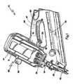
- FIG. 1 is a front perspective view of a fastener-driving tool incorporating the present lockout system;
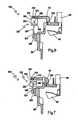
- FIG. 2 is a fragmentary vertical cross-section of the tool of FIG. 1 shown in the rest position;
- FIG. 3 is a fragmentary vertical cross-section of the tool of FIG. 2 shown in the pre-firing position;
- FIG. 4 is a fragmentary exploded perspective view of the tool of FIG. 1, specifically the combustion chamber and electromechanical chamber lockout device;
- FIG. 5 is a schematic view of an alternate embodiment to the lockout system of FIGs. 2-4 shown in the lockout position;
- FIG. 6 is a fragmentary vertical cross-section of an alternate embodiment to the delay system of FIGs. 1-4 using a dashpot shown in the vent or rest position;
- FIG. 7 is a fragmentary vertical cross-section of the embodiment of FIG. 6 shown in the pre-firing position;
- FIG. 8 is a fragmentary vertical cross-section of a second alternate embodiment to the delay system, of FIGs. 1-4 using an electromagnet lockout device;
- FIG. 9 is a fragmentary vertical cross-section of a third alternate embodiment to the delay system of FIGs. 1-4;
- FIG. 10 is a schematic side elevation of a fourth alternate embodiment to the delay system of FIGs. 1-4 shown in a rest position;
- FIG. 11 is a schematic side elevation of the embodiment of FIG. 10 shown in the locked or delayed position associated with pre-firing;
- FIG. 12 is a schematic side elevation of an alternate embodiment to the delay system of FIGs. 10-11 in an orientation transverse to that of FIGs. 10 and 11 in a rest position; and
- FIG. 13 is a schematic side elevation of the embodiment of FIG. 12 shown in the locked or delayed position associated with pre-firing.
- Referring now to FIGs. 1 -3, a combustion-powered fastener-driving tool incorporating the present invention is generally designated 10 and preferably is of the general type described in detail in the patents listed above and incorporated by reference in the present application. A
housing 12 of thetool 10 encloses a self-contained internal power source 14 (FIG. 2) within a housingmain chamber 16. As in conventional combustion tools, thepower source 14 is powered by internal combustion and includes acombustion chamber 18 that communicates with acylinder 20. Apiston 22 reciprocally disposed within thecylinder 20 is connected to the upper end of adriver blade 24. As shown in FIG. 2, an upper limit of the reciprocal travel of thepiston 22 is referred to as a pre-firing position, which occurs just prior to firing, or the ignition of the combustion gases which initiates the downward driving of thedriver blade 24 to impact a fastener (not shown) to drive it into a workpiece. - Through depression of a
trigger 26, an operator induces combustion within thecombustion chamber 18, causing thedriver blade 24 to be forcefully driven downward through a nosepiece 28 (FIG. 1). Thenosepiece 28 guides thedriver blade 24 to strike a fastener that had been delivered into the nosepiece via afastener magazine 30. - Included in the
nosepiece 28 is aworkpiece contact element 32, which is connected, through a linkage orupper probe 34 to areciprocating valve sleeve 36, an upper end of which partially defines thecombustion chamber 18. Depression of thetool housing 12 against theworkpiece contact element 32 in a downward direction as seen in FIG. 1 (other operational orientations are contemplated as are known in the art), causes the workpiece contact element to move from a rest position to a firing position. This movement overcomes the normally downward biased orientation of theworkpiece contact element 32 caused by a spring 38 (shown hidden in FIG. 1). It is contemplated that the location of thespring 38 may vary to suit the application, and locations displaced farther from thenosepiece 28 are envisioned. - Through the
linkage 34, theworkpiece contact element 32 is connected to and reciprocally moves with, thevalve sleeve 36. In the rest position (FIG. 2), thecombustion chamber 18 is not sealed, since there is anannular gap 40 separating thevalve sleeve 36 and acylinder head 42, which accommodates achamber switch 44 and aspark plug 46. Specifically, there is an upper gap 40U near thecylinder head 42, and alower gap 40L near the upper end of thecylinder 20. In the preferred embodiment of thepresent tool 10, thecylinder head 42 also is the mounting point for a coolingfan 48 and afan motor 49 powering the cooling fan. The fan and at least a portion of the motor extend into thecombustion chamber 18 as is known in the art and described in the patents which have been incorporated by reference above. In the rest position depicted in FIG. 2, thetool 10 is disabled from firing because thecombustion chamber 18 is not sealed at the top with thecylinder head 42, and thechamber switch 44 is open. - Firing is enabled when an operator presses the
workpiece contact element 32 against a workpiece. This action overcomes the biasing force of thespring 38, causes thevalve sleeve 36 to move upward relative to thehousing 12, closing thegaps 40U and 40L and sealing thecombustion chamber 18 until thechamber switch 44 is activated. This operation also induces a measured amount of fuel to be released into thecombustion chamber 18 from a fuel canister 50 (shown in fragment). - Upon a pulling of the
trigger 26, thespark plug 46 is energized, igniting the fuel and air mixture in thecombustion chamber 18 and sending thepiston 22 and thedriver blade 24 downward toward the waiting fastener for entry into the workpiece. As thepiston 22 travels down the cylinder, it pushes a rush of air which is exhausted through at least one petal orcheck valve 52 and at least onevent hole 53 located beyond piston displacement (FIG. 2). At the bottom of the piston stroke or the maximum piston travel distance, thepiston 22 impacts aresilient bumper 54 as is known in the art. With thepiston 22 beyond theexhaust check valve 52, high pressure gasses vent from thecylinder 20 until near atmospheric pressure conditions are obtained and thecheck valve 52 closes. Due to internal pressure differentials in thecylinder 20, thepiston 22 is returned to the pre-firing position shown in FIG. 2. - As described above, one of the issues confronting designers of combustion-powered tools of this type is the need for a rapid return of the
piston 22 to pre-firing position and improved control of thechamber 18 prior to the next cycle. This need is especially critical if the tool is to be fired in a repetitive cycle mode, where an ignition occurs each time theworkpiece contact element 32 is retracted, and during which time thetrigger 26 is continually held in the pulled or squeezed position. - Referring now to FIGs. 2-4, to accommodate these design concerns, the
present tool 10 preferably incorporates a lockout device, generally designated 60 and configured for preventing the reciprocation of thevalve sleeve 36 from the closed or firing position until thepiston 22 returns to the pre-firing position. This holding, delaying or locking function of thelockout device 60 is operational for a specified period of time required for thepiston 22 to return to the pre-firing position. Thus, the operator using thetool 10 in a repetitive cycle mode can lift the tool from the workpiece where a fastener was just driven, and begin to reposition the tool for the next firing cycle. Due to the shorter firing cycle times inherent with repetitive cycle operation, thelockout device 60 ensures that thecombustion chamber 18 will remain sealed, and the differential gas pressures maintained so that thepiston 22 will be returned before a premature opening of thechamber 18, which would normally interrupt piston return. With thepresent lockout device 60, thepiston 22 return and subsequent opening of thecombustion chamber 18 can occur while thetool 10 is being moved toward the next workpiece location. - More specifically, and referring to FIGs. 2-4, the
lockout device 60 includes anelectromagnet 62 configured for engaging a sliding cam or latch 64 which transversely reciprocates relative tovalve sleeve 36 for preventing the movement of thevalve sleeve 36 for a specified amount of time. This time period is controlled by a control circuit or program 66 (FIG. 1) embodied in a central processing unit or control module 67 (shown hidden), typically housed in a handle portion 68 (FIG. 1) of thehousing 12. While other orientations are contemplated, in the preferred embodiment, theelectromagnet 62 is coupled with the slidinglatch 64 such that the axis of the electromagnet's coil and the latch is transverse to the driving motion of thetool 10. Thelockout device 60 is mounted in operational relationship to anupper portion 70 of thecylinder 20 so that sliding legs orcams 72 of thelatch 64 having angled ends 74 pass throughapertures 76 in a mountingbracket 78 and thehousing 12 to engage a recess orshoulder 80 in thevalve sleeve 36 once it has reached the firing position. As is seen in FIG. 4, thelatch 64 is biased to the locked position by aspring 82 and is retained by theelectromagnet 62 for a specified time interval. - For the proper operation of the
lockout device 60, thecontrol program 66 is configured so that theelectromagnet 62 is energized for the proper period of time to allow thepiston 22 to return to the pre-firing position subsequent to firing. As the operator pushes thetool 10 against the workpiece and thecombustion chamber 18 is sealed, thelatch 64 is biased against a wear plate 83 (FIG. 4), extending thelegs 72. More specifically, when thecontrol program 66, triggered by an operational sequence of switches (not shown) indicates that conditions are satisfactory to deliver a spark to thecombustion chamber 18, theelectromagnet 62 is energized by thecontrol program 66 for approximately 100 msec. During this event, thelatch 64 is held in position, thereby preventing thechamber 18 from opening. The period of time of energization of theelectromagnet 62 would be such that enough dwell is provided to satisfy all operating conditions for full piston return. This period may vary to suit the application. - The
control program 66 is configured so that once thepiston 22 has returned to the pre-firing position; theelectromagnet 62 is deenergized, reducing the transversely directed force on thelegs 72. As the user lifts thetool 10 from the workpiece, and following timed de-energization of theelectromagnet 62, thespring 38 will overcome the force of thespring 82, and any residual force of theelectromagnet 62, and will cause thevalve sleeve 36 to move to the rest or extended position, opening up thecombustion chamber 18 and thegaps 40U, 40L. This movement is facilitated by the cammed surfaces 74 of thelegs 72, and retracts the legs as thevalve sleeve 36 opens. As is known, thevalve sleeve 36 must be moved downwardly away from thefan 48 to open thechamber 18 for exchanging gases in the combustion chamber and preparing for the next combustion. - In the preferred embodiment, a
cover 86 encloses thespring 82, thelatch member 64 and theelectromagnet 62, and secures these items to the mountingbracket 78 through the use ofeyelets 88 and suitable threaded fasteners, rivets or other fasteners known in the art (not shown). While in FIGs. 1-4 theelectromagnet 62 is shown on a front of thehousing 12, it is contemplated that it can be located elsewhere on thetool 10 or within thehousing 12 as desired. - Referring now to FIG. 5, an alternate embodiment of the
lockout device 60 is designated 90. Shared components of thedevices 60 and 90 are designated with identical reference numbers. The main difference between the devices is that thelatch 64 is replaced by pivotinglatch member 92 having alug 94 which engages arecess 96 in thevalve sleeve 36 once it reaches the closed position. Thelatch member 92 is pivotable about anaxis 98 such as a pin secured to thecylinder 20 or elsewhere on thetool 10. Theaxis 98 is generally transverse to the direction of reciprocation of thevalve sleeve 36. Areciprocating plunger 100 of asolenoid 102 is associated with thelatch member 92 to push the lug into engagement upon solenoid energization. Theplunger 100 is preferably provided with aspring 104 for biasing pivotinglatch member 92 against thevalve sleeve 36 such that thelug 94 can fall into therecess 96. Thevalve sleeve 36 can return to the rest position to open thecombustion chamber 18 upon timed de-energization of thesolenoid 102. Retraction of theplunger 100 causes thespring 38 to pull thevalve sleeve 36 downward, thus moving down the sloped upper surface of thelug 94 and forcing thelatch member 92 out of engagement with therecess 96. - Referring now to FIGs. 6 and 7, another alternate embodiment to the
lockout delay device 60 is generally designated 120. In this embodiment, the components of thetool 10 which are identical have been designated with the same reference numbers. The main difference between thedevice 120 and thelockout device 60 is that instead of theelectromagnet 62, thelatch 64, thespring 82 and thecover 86, at least one mechanical dashpot generally designated 122 is provided. In general, thedashpot 122 is a mechanical device used for dampening or delaying motion between two points. In this case, the two points are thevalve sleeve 36 and thecylinder head 42. While only onedashpot 122 is illustrated, the number and varied positioning of additional dashpots is contemplated depending on the application. - The
dashpot 122 has two ends, each of which is attachable to either of thevalve sleeve 36 or a fixed position associated with thepower source 14. In the preferred embodiment, the fixed position is on thecylinder head 42. Aside from thecylinder head 42, other portions of thepower source 14 which, during combustion cycles do not move relative to thevalve sleeve 36 are also contemplated as being the fixed position. A first orrod end 124 is attachable to thevalve sleeve 36 at apin location 126 and includes apiston rod 128 and apiston 130. - As is known in the art, the
dashpot 122 employs a slidable seal between a piston and a cylinder, pneumatic action or a viscous, fluid-like material to provide the delay or dampening movement. Asecond end 132 of thedashpot 122 is securable to thecylinder head 42 at a mountinglocation 134 and forms a cylinder with anopen end 136 dimensioned to slidingly receive thepiston 130. At least one vent opening orhole 138 is positioned on thecylinder 132 to correspond to the position of thevalve sleeve 36 in the area of contact with aseal 139 on thecylinder head 42 prior to the pre-firing position (shown in FIG. 7). In this manner, thedashpot 122 only provides a delaying function when thepiston 130 is disposed above thevent hole 138. The present dashpot design incorporates acheck valve 140 to allow air in thedashpot cylinder 132 to be expelled when thetool 10 is actuated against the work. This prevents additional loading or feedback to the user. - In operation of the embodiment depicted in FIGs. 6 and 7, upon combustion, the dashpot effect, in this case vacuum formation, between the
piston 130 and thecylinder 132 is such that the opening of thecombustion chamber 18 is delayed for an amount of time allowing for thepiston 22 to reach the uppermost or the pre-firing position. Once the operator lifts thetool 10 from the workpiece, thevalve sleeve 36 begins to move away from thecylinder head 42, and is delayed only by thedashpot 122. The additional delaying action provided by thedashpot 122 is terminated or released once thepiston 130 passes thevent hole 138. - When the
tool 10 is raised off of the work surface, thedashpot 122 provides a controlled release rate of the chamber via an orifice-regulated intake of return air through anorifice 142. Preferably, this occurs over the portion of the movement of thevalve sleeve 36 when the main combustion chamber seals 139 are effective. At the point where theseals 139 unseat through movement of thevalve sleeve 36, thedashpot piston 130 exposes thevent hole 138, or series of holes, that makes the dashpot ineffective. The remainder of the chamber movement continues unimpeded. This minimizes the overall return opening time of thecombustion chamber 18. - Referring now to FIG. 8, depicting the
valve sleeve 36 in the pre-firing position, a second alternate embodiment to the lockout device is generally designated 150. Shared components with the embodiments of FIGs. 1-7 are designated with identical reference numbers. A main distinction of theembodiment 150 is that the delay of the opening of thevalve sleeve 36 during the combustion cycle is obtained through anelectromagnetic device 152 mounted to a fixed position on thepower source 14, preferably thecylinder head 42, however other locations are contemplated. It will be seen that theelectromagnetic device 152 operates along an axis which is parallel to the direction of reciprocation of thepiston 22 and thevalve sleeve 36. As is the case with theelectromagnetic device 62, thedevice 152 is connected to thecontrol program 66 and theCPU 67. Theelectromagnetic device 152 depends from thecylinder head 42 so that acontact end 154 is in operational relationship to thevalve sleeve 36. - In the present embodiment, the
valve sleeve 36 is provided with at least one radially projectingcontact formation 156 constructed and arranged to be in registry with thecontact end 154 of thedevice 152. While in the preferred version of this embodiment thecontact formation 156 is shaped as a plate, the number, shape and positioning of the contact formation may vary to suit the application, as long as there is a sufficient magnetic attraction between theelectromagnetic device 152 and theformation 156 when thevalve sleeve 36 reaches the closed or pre-firing position (FIG. 3). - Upon reaching the pre-firing position, energization of the
electromagnetic device 152 will create sufficient magnetic force to hold thecontact plate 156, and by connection thevalve sleeve 36, from reciprocal movement for a predetermined amount of time (determined by the control program 66) sufficient to permit return of thepiston 22 to the pre-firing position (FIG. 3). Upon expiration of the predetermined amount of time controlled by thecontrol program 66, theelectromagnetic device 152 is deenergized, releasing thevalve sleeve 36 so that internal gases can be exchanged for the next operational combustion cycle, as described above. - Referring now to FIG. 9, still another alternate embodiment of the lockout devices described above is generally designated 160. Shared components of the
embodiments embodiment 160 operates similarly to theembodiment 150 in that it exerts an axial holding force on thevalve sleeve 36 which is generally parallel to the direction of valve sleeve reciprocation. - In FIG. 9, the
valve sleeve 36 is provided with a generally axially extendingpin 162 made of a rigid, magnetic material such as a durable metal. Anelectromagnetic device 164 is secured to a fixed location on thepower source 14, preferably on thecylinder head 42, however other locations are contemplated provided they remain in a fixed position relative to reciprocation of thevalve sleeve 36. Theelectromagnetic device 164 is controlled by thecontrol program 66 and is provided in a tubular or sleeve-like construction, defining an elongate passageway 166 dimensioned for matingly receiving thepin 162. Upon thevalve sleeve 36 reaching the pre-firing position (FIG. 3), thecontrol program 66 energizes theelectromagnetic device 164, creating sufficient magnetic force to hold thepin 162 and thus prevent thevalve sleeve 36 from moving reciprocally. Thecontrol program 66 also initiates a timer (not shown) which determines the amount of time thedevice 164 is energized, corresponding to the amount of time needed for piston return. As such, thepiston 22 is permitted sufficient time to return to the pre-firing position prior to the next combustion cycle event. - Referring now to FIGs. 10 and 11, still another alternate embodiment to the lockout devices described above is generally designated 170. In this embodiment, a reciprocating
electromagnetic solenoid 172 under the control of thecontrol program 66 and theCPU 67 is oriented in thehousing 12 to operate so that an axis of reciprocation is generally parallel to the movement of thevalve sleeve 36. An operational orfree end 174 of thesolenoid 172 is configured as a dogleg, having anelongate slot 176 which engages atransverse pin 178 in arotating cam 180. Thepin 178 is located at oneend 182 of thecam 180, and a pivot axis or pin 184 is located at anopposite end 186. A lockinglobe 188 is formed on theopposite end 186 and is configured for engaging alower end 190 of thevalve sleeve 36. - A
biasing device 192 such as a return spring is located on thesolenoid 172 to return it, upon deenergization, to a rest or unlocked position shown in FIG. 10. Thespring 192 is retained upon amain shaft 194 of thesolenoid 172 by an annular, radially projectingflange 196. As is seen in FIG. 10, as long as thesolenoid 172 is deenergized, the action of thespring 192 keeps the lockinglobe 188 clear of thevalve sleeve 36, which is permitted free reciprocal movement as occurs prior to combustion. - Referring now to FIG. 11, soon after the
valve sleeve 36 reaches the closed or pre-firing position and conditions are satisfied for combustion (FIG. 3), thecontrol circuit 66 energizes thesolenoid 172 to retract themain shaft 194 and overcome the force generated by thespring 192. The resulting linear movement of theshaft 194 acts on theend 182 of thecam 180, rotating the lockinglobe 188 into an engagement position with thelower end 190 of thevalve sleeve 36. During this rotation, thetransverse pin 178 moves in theslot 176. - As is the case with the other locking systems described above, the timing of the energization of the
solenoid 172 is determined to be sufficient for achieving return of thepiston 22 to the pre-firing position after combustion. At the conclusion of the preset energization period, thesolenoid 172 is deenergized, and the force of thespring 192 causes movement of thelocking lobe 188 away from thevalve sleeve 36. Opening of thecombustion chamber 18 is thus permitted for purging of exhaust gas. - Referring now to FIGs. 12 and 13, another embodiment of the
lockout device 170 is generally designated 200. Shared components with thelockout device 170 are designated with identical reference numbers. Essentially, themechanism 200 differs from themechanism 170 by being oriented in thetool housing 12 so that the axis of reciprocation of a solenoidmain shaft 202 is oriented generally normally or perpendicular to the axis of reciprocation of thevalve sleeve 36. The solenoidmain shaft 202 differs from themain shaft 194 in the positioning of thereturn spring 192 and aradially projecting flange 204 at anend 206 of the main shaft opposite adogleg end 208. Also, thespring 192 and theflange 204 are on an opposite end of asolenoid unit 210 from the corresponding structure on themechanism 170. Aslot 212 in thedogleg end 208 extends angularly relative to the axis of reciprocation of themain shaft 202, and engages thetransverse pin 178 of therotating cam 180. - With the
solenoid 210 deenergized, thereturn spring 192 pushes theannular flange 204 away from thevalve sleeve 36, allowing for free valve sleeve movement up to the time of combustion. Referring now to FIG. 13, after thevalve sleeve 36 has reached its uppermost position (FIG. 3) and conditions are satisfied for combustion, thecontrol circuit 66 energizes thesolenoid 210, overcoming the biasing force of thereturn spring 192, moving themain shaft 202 toward thevalve sleeve 36 and causing thetransverse pin 178 to move in theslot 212 so that therotating cam 180 moves into locking engagement with thelower end 190 of thevalve sleeve 36. This position is maintained by thecontrol circuit 66 as in the case of themechanism 170 for a designated period of time until thepiston 22 to the pre-firing position. - While a particular embodiment of the present combustion chamber control for a combustion-powered fastener-driving tool has been described herein, it will be appreciated by those skilled in the art that changes and modifications may be made thereto without departing from the invention in its broader aspects and as set forth in the following claims.
Claims (5)
- A combustion-powered fastener-driving tool (10), comprising:- a combustion-powered power source (14);- a valve sleeve (36) reciprocable relative to said power source (14) between a rest position and a firing position; and- a lockout device (60) in operational proximity to said valve sleeve (36) and configured for automatically preventing the reciprocation of said valve sleeve (36) from said firing position until a piston (22) in said power source (14) returns to a pre-firing position.characterized in that
said lockout device (60) comprises at least one dashpot (122) connected between a fixed position on said tool (10) and said reciprocating valve sleeve (36) and
configured for accommodating progressive opening of said valve sleeve (36) to said rest position. - The tool (10) according to claim 1, wherein said fixed position is a cylinder head (42), and said at least one dashpot (122) includes a first end connected to said cylinder head (42), and a second end connected to said valve sleeve (36), said dashpot (122) including a piston (22) and a cylinder (132) configured for slidingly receiving said piston (22).
- The tool (10) according to claim 2, further including a vent hole (53) in said dashpot cylinder (132) disposed such that a delaying function is provided when said piston (22) is disposed between the vent hole (53) and the closest of said ends.
- The tool (10) according to one of the preceding claims, wherein said power source (14) includes a cylinder (20) defining a space in which a piston (22) and an attached driver blade (24) reciprocates as a result of combustion, and a combustion chamber (18) configured for being closed during the combustion, and wherein, in said firing position, said valve sleeve (36) closes said combustion chamber (18), and wherein said at least one dashpot (122) is operatively connected between a fixed position associated with said power source (14) and said valve sleeve (36) for delaying opening of said combustion chamber after firing.
- The tool (10) according to claim 4, wherein said fixed position is a cylinder head (42) partially defining said combustion chamber (18), said at least one dashpot (122) being connected between said valve sleeve (36) and said cylinder head (42) for suspending said valve sleeve (36) from said cylinder head (42).
Applications Claiming Priority (3)
| Application Number | Priority Date | Filing Date | Title |
|---|---|---|---|
| US54305304P | 2004-02-09 | 2004-02-09 | |
| US11/028,450US7163134B2 (en) | 2004-02-09 | 2005-01-03 | Repetitive cycle tool logic and mode indicator for combustion powered fastener-driving tool |
| EP05712260AEP1713620B1 (en) | 2004-02-09 | 2005-01-31 | Combustion chamber control for combustion-powered fastener-driving tool |
Related Parent Applications (2)
| Application Number | Title | Priority Date | Filing Date |
|---|---|---|---|
| EP05712260.8Division | 2005-01-31 | ||
| EP05712260ADivisionEP1713620B1 (en) | 2004-02-09 | 2005-01-31 | Combustion chamber control for combustion-powered fastener-driving tool |
Publications (4)
| Publication Number | Publication Date |
|---|---|
| EP1813394A2true EP1813394A2 (en) | 2007-08-01 |
| EP1813394A3 EP1813394A3 (en) | 2007-08-22 |
| EP1813394B1 EP1813394B1 (en) | 2008-11-26 |
| EP1813394B8 EP1813394B8 (en) | 2010-09-15 |
Family
ID=34829664
Family Applications (3)
| Application Number | Title | Priority Date | Filing Date |
|---|---|---|---|
| EP05712261AExpired - LifetimeEP1713621B1 (en) | 2004-02-09 | 2005-01-31 | Repetitive cycle tool logic and mode indicator for combustion powered fastener-driving tool |
| EP07108060AExpired - LifetimeEP1813394B8 (en) | 2004-02-09 | 2005-01-31 | Combustion chamber control for combustion-powered fastener-driving tool |
| EP05712260AExpired - LifetimeEP1713620B1 (en) | 2004-02-09 | 2005-01-31 | Combustion chamber control for combustion-powered fastener-driving tool |
Family Applications Before (1)
| Application Number | Title | Priority Date | Filing Date |
|---|---|---|---|
| EP05712261AExpired - LifetimeEP1713621B1 (en) | 2004-02-09 | 2005-01-31 | Repetitive cycle tool logic and mode indicator for combustion powered fastener-driving tool |
Family Applications After (1)
| Application Number | Title | Priority Date | Filing Date |
|---|---|---|---|
| EP05712260AExpired - LifetimeEP1713620B1 (en) | 2004-02-09 | 2005-01-31 | Combustion chamber control for combustion-powered fastener-driving tool |
Country Status (14)
| Country | Link |
|---|---|
| US (2) | US7163134B2 (en) |
| EP (3) | EP1713621B1 (en) |
| JP (1) | JP4673324B2 (en) |
| KR (2) | KR20070050394A (en) |
| AT (3) | ATE390991T1 (en) |
| AU (2) | AU2005212179B2 (en) |
| BR (2) | BRPI0507388A (en) |
| CA (2) | CA2552840C (en) |
| DE (3) | DE602005005791T2 (en) |
| DK (3) | DK1713621T3 (en) |
| ES (1) | ES2303227T3 (en) |
| MX (1) | MXPA06008640A (en) |
| NZ (1) | NZ548481A (en) |
| WO (2) | WO2005077606A1 (en) |
Families Citing this family (43)
| Publication number | Priority date | Publication date | Assignee | Title |
|---|---|---|---|---|
| US7163134B2 (en)* | 2004-02-09 | 2007-01-16 | Illinois Tool Works Inc. | Repetitive cycle tool logic and mode indicator for combustion powered fastener-driving tool |
| US7341171B2 (en)* | 2004-02-09 | 2008-03-11 | Illinois Tool Works Inc. | Fan control for combustion-powered fastener-driving tool |
| JP4395841B2 (en)* | 2004-09-29 | 2010-01-13 | 日立工機株式会社 | Combustion type driving tool |
| AU305500S (en)* | 2005-07-07 | 2006-02-16 | Bosch Gmbh Robert | Staple gun |
| USD526551S1 (en)* | 2005-07-29 | 2006-08-15 | Hitachi Koki Co., Ltd. | Portable gas nailing machine |
| JP4788228B2 (en)* | 2005-08-08 | 2011-10-05 | マックス株式会社 | Combustion chamber holding mechanism in gas combustion type driving tool |
| NZ568396A (en)* | 2005-11-17 | 2011-06-30 | Illinois Tool Works | Variable ignition delay for combustion nailer |
| US20090152316A1 (en)* | 2005-11-17 | 2009-06-18 | Moeller Larry M | Selectable firing mode with electromechanical lockout for combustion-powered fastener -driving tool |
| US20070108249A1 (en)* | 2005-11-17 | 2007-05-17 | Moeller Larry M | Motor control for combustion nailer based on operating mode |
| US8770456B2 (en)* | 2006-10-16 | 2014-07-08 | Illinois Tool Works Inc. | Recharge cycle function for combustion nailer |
| JP4899840B2 (en)* | 2006-12-05 | 2012-03-21 | マックス株式会社 | Gas fired driving tool |
| JP4697161B2 (en)* | 2007-03-15 | 2011-06-08 | 日立工機株式会社 | Combustion power tool |
| JP5064958B2 (en)* | 2007-10-04 | 2012-10-31 | 株式会社マキタ | Driving tool |
| USD600085S1 (en)* | 2007-11-20 | 2009-09-15 | Arrow Fastener Company, Inc. | Staple gun with wire guide |
| DE102008000137A1 (en)* | 2008-01-23 | 2009-07-30 | Hilti Aktiengesellschaft | Internal combustion setting device |
| US7784560B2 (en)* | 2008-03-31 | 2010-08-31 | Illinois Tool Works Inc. | Cap assembly of a fastener-driving tool having switch mechanism incorporated therein for switching modes of operation of the fastener-driving tool |
| DE102008000909A1 (en)* | 2008-04-01 | 2009-10-08 | Hilti Aktiengesellschaft | Internal combustion setting device |
| US8336749B2 (en)* | 2009-03-31 | 2012-12-25 | Illinois Tool Works Inc. | Single switched dual firing condition combustion nailer |
| US8387846B2 (en) | 2009-06-08 | 2013-03-05 | Illinois Tool Works Inc | Fastening tool with blind guide work contact tip |
| DE102009041828A1 (en)* | 2009-09-18 | 2011-03-24 | Hilti Aktiengesellschaft | Device for transferring energy to e.g. pin, has closing unit for temporarily closing supply channel, and control unit connected with closing unit for opening and closing of closing unit according to predetermined conditions |
| US8261847B2 (en)* | 2009-10-09 | 2012-09-11 | Illinois Tool Works Inc. | Automatic low power consumption mode for combustion tools |
| FR2955517B1 (en)* | 2010-01-26 | 2012-04-20 | Prospection & Inventions | PRESSURE-TEMPERATURE ABATE AND FUEL CARTRIDGE, FUEL TRANSFER DEVICE, AND HAND FASTENING TOOL WITH PRESSURE SENSOR |
| JP5429010B2 (en)* | 2010-04-02 | 2014-02-26 | マックス株式会社 | Gas combustion type fastening machine |
| DE102010063173A1 (en)* | 2010-12-15 | 2012-06-21 | Hilti Aktiengesellschaft | A bolt gun and method for operating a bolt gun |
| EP2633956B1 (en)* | 2012-03-02 | 2016-03-02 | Stanley Fastening Systems L.P. | Fastening tool with dual pneumatic handle |
| US9550288B2 (en) | 2012-10-22 | 2017-01-24 | Illinois Tool Works Inc. | Fastener-driving tool including a reversion trigger |
| US9486907B2 (en) | 2013-01-15 | 2016-11-08 | Illinois Tool Works Inc. | Reversion trigger for combustion-powered fastener-driving tool |
| DE102013106657A1 (en) | 2013-06-25 | 2015-01-08 | Illinois Tool Works Inc. | Driving tool for driving fasteners into a workpiece |
| DE102013106658A1 (en) | 2013-06-25 | 2015-01-08 | Illinois Tool Works Inc. | Driving tool for driving fasteners into a workpiece |
| US9662776B2 (en) | 2013-12-17 | 2017-05-30 | Illinois Tool Works Inc. | Fastener-driving tool including a reversion trigger with a damper |
| US10759031B2 (en) | 2014-08-28 | 2020-09-01 | Power Tech Staple and Nail, Inc. | Support for elastomeric disc valve in combustion driven fastener hand tool |
| US9862083B2 (en) | 2014-08-28 | 2018-01-09 | Power Tech Staple and Nail, Inc. | Vacuum piston retention for a combustion driven fastener hand tool |
| EP3090836A1 (en) | 2015-05-06 | 2016-11-09 | Illinois Tool Works Inc. | Tool for driving fixation means with improved safety device |
| EP3181295A1 (en)* | 2015-12-18 | 2017-06-21 | HILTI Aktiengesellschaft | Internal combustion operated driving tool |
| WO2018203128A2 (en) | 2017-05-03 | 2018-11-08 | Signode Industrial Groupl Llc | Electrically driven staple device |
| US11034005B2 (en) | 2017-08-03 | 2021-06-15 | Tti (Macao Commercial Offshore) Limited | Dry-fire lockout mechansim for a powered fastener driver |
| US11065749B2 (en) | 2018-03-26 | 2021-07-20 | Tti (Macao Commercial Offshore) Limited | Powered fastener driver |
| EP3578308A1 (en)* | 2018-06-06 | 2019-12-11 | HILTI Aktiengesellschaft | Setting device |
| US11624314B2 (en) | 2018-08-21 | 2023-04-11 | Power Tech Staple and Nail, Inc. | Combustion chamber valve and fuel system for driven fastener hand tool |
| US11491623B2 (en) | 2019-10-02 | 2022-11-08 | Illinois Tool Works Inc. | Fastener driving tool |
| WO2022067256A1 (en) | 2020-09-28 | 2022-03-31 | Black & Deck, Inc. | Fastener driving tool trigger assembly |
| US11794323B2 (en) | 2021-03-11 | 2023-10-24 | Illinois Tool Works Inc. | Fastener-driving tool with chamber member retaining assembly |
| US12358112B2 (en) | 2021-03-11 | 2025-07-15 | Illinois Tool Works Inc. | Fastener-driving tool with chamber member retaining assembly |
Family Cites Families (34)
| Publication number | Priority date | Publication date | Assignee | Title |
|---|---|---|---|---|
| US32452A (en) | 1861-05-28 | Improvement in telegraphic apparatus | ||
| US4403722A (en) | 1981-01-22 | 1983-09-13 | Signode Corporation | Combustion gas powered fastener driving tool |
| US4483474A (en) | 1981-01-22 | 1984-11-20 | Signode Corporation | Combustion gas-powered fastener driving tool |
| IN157475B (en) | 1981-01-22 | 1986-04-05 | Signode Corp | |
| US4483473A (en)* | 1983-05-02 | 1984-11-20 | Signode Corporation | Portable gas-powered fastener driving tool |
| US4721240A (en) | 1986-07-02 | 1988-01-26 | Senco Products, Inc. | Cam-controlled self-contained internal combustion fastener driving tool |
| US4717060A (en) | 1986-07-02 | 1988-01-05 | Senco Products, Inc. | Self-contained internal combustion fastener driving tool |
| US5133329A (en) | 1991-11-25 | 1992-07-28 | Illinois Tool Works Inc. | Ignition system for combustion-powered tool |
| US5197646A (en) | 1992-03-09 | 1993-03-30 | Illinois Tool Works Inc. | Combustion-powered tool assembly |
| US5263439A (en) | 1992-11-13 | 1993-11-23 | Illinois Tool Works Inc. | Fuel system for combustion-powered, fastener-driving tool |
| US5415136A (en)* | 1993-08-30 | 1995-05-16 | Illinois Tool Works Inc. | Combined ignition and fuel system for combustion-powered tool |
| US5592580A (en) | 1994-11-10 | 1997-01-07 | Illinois Tool Works Inc. | System for controlling energy output of combustion-powered, fastener-driving tool |
| US6123241A (en) | 1995-05-23 | 2000-09-26 | Applied Tool Development Corporation | Internal combustion powered tool |
| US5687897A (en)* | 1995-07-28 | 1997-11-18 | Campbell Hausfeld/Scott Fetzer Company | Dual mode pneumatic tool |
| US5909836A (en) | 1997-10-31 | 1999-06-08 | Illinois Tool Works Inc. | Combustion powered tool with combustion chamber lockout |
| US6145724A (en) | 1997-10-31 | 2000-11-14 | Illinois Tool Works, Inc. | Combustion powered tool with combustion chamber delay |
| US6116489A (en) | 1998-10-28 | 2000-09-12 | Pow-R-Tools Corporation | Manually operable internal combustion-type impact tool with reduced recycler stroke |
| US6783042B2 (en)* | 2001-03-07 | 2004-08-31 | Edward Kaufer | Pocket tape dispenser |
| US6543664B2 (en)* | 2001-03-16 | 2003-04-08 | Illinois Tool Works Inc | Selectable trigger |
| JP4055509B2 (en)* | 2002-08-09 | 2008-03-05 | 日立工機株式会社 | Combustion type driving tool |
| JP4135069B2 (en)* | 2002-08-09 | 2008-08-20 | 日立工機株式会社 | Combustion type driving tool |
| CN1273270C (en)* | 2002-08-09 | 2006-09-06 | 日立工机株式会社 | Nailing gun using gas as power |
| US6983871B2 (en)* | 2002-08-09 | 2006-01-10 | Hitachi Koki Co., Ltd. | Combustion-powered nail gun |
| JP3925793B2 (en)* | 2002-08-09 | 2007-06-06 | 日立工機株式会社 | Combustion type driving tool |
| DE10259775A1 (en)* | 2002-12-19 | 2004-07-08 | Hilti Ag | Combustion force operated setting tool, e.g. for driving nails into a surface, has a fan for venting and cooling the combustion chamber, the operation of which is controlled in an ambient temperature dependent manner |
| US6715655B1 (en)* | 2003-01-03 | 2004-04-06 | Illinois Tool Works Inc. | Combustion chamber lock-out mechanism |
| DE602004013860D1 (en)* | 2003-03-19 | 2008-07-03 | Hitachi Koki Kk | Combustion-powered tool with a device to prevent overheating of the mechanical components in the tool |
| JP4269912B2 (en)* | 2003-03-19 | 2009-05-27 | 日立工機株式会社 | Combustion power tool |
| US6722550B1 (en)* | 2003-05-09 | 2004-04-20 | Illinois Tool Works Inc. | Fuel level indicator for combustion tools |
| JP4665432B2 (en)* | 2003-06-20 | 2011-04-06 | 日立工機株式会社 | Combustion power tool |
| US7487898B2 (en)* | 2004-02-09 | 2009-02-10 | Illinois Tool Works Inc. | Combustion chamber control for combustion-powered fastener-driving tool |
| US7163134B2 (en)* | 2004-02-09 | 2007-01-16 | Illinois Tool Works Inc. | Repetitive cycle tool logic and mode indicator for combustion powered fastener-driving tool |
| US7341171B2 (en)* | 2004-02-09 | 2008-03-11 | Illinois Tool Works Inc. | Fan control for combustion-powered fastener-driving tool |
| US7137541B2 (en)* | 2004-04-02 | 2006-11-21 | Black & Decker Inc. | Fastening tool with mode selector switch |
- 2005
- 2005-01-03USUS11/028,450patent/US7163134B2/ennot_activeExpired - Lifetime
- 2005-01-31BRBRPI0507388-0Apatent/BRPI0507388A/ennot_activeIP Right Cessation
- 2005-01-31JPJP2006552166Apatent/JP4673324B2/ennot_activeExpired - Fee Related
- 2005-01-31DEDE602005005791Tpatent/DE602005005791T2/ennot_activeExpired - Lifetime
- 2005-01-31KRKR1020067015873Apatent/KR20070050394A/ennot_activeWithdrawn
- 2005-01-31ATAT05712260Tpatent/ATE390991T1/ennot_activeIP Right Cessation
- 2005-01-31WOPCT/US2005/002748patent/WO2005077606A1/ennot_activeApplication Discontinuation
- 2005-01-31BRBRPI0507106-2Apatent/BRPI0507106A/ennot_activeIP Right Cessation
- 2005-01-31EPEP05712261Apatent/EP1713621B1/ennot_activeExpired - Lifetime
- 2005-01-31CACA002552840Apatent/CA2552840C/ennot_activeExpired - Lifetime
- 2005-01-31CACA002553117Apatent/CA2553117C/ennot_activeExpired - Lifetime
- 2005-01-31DEDE602005011327Tpatent/DE602005011327D1/ennot_activeExpired - Fee Related
- 2005-01-31EPEP07108060Apatent/EP1813394B8/ennot_activeExpired - Lifetime
- 2005-01-31WOPCT/US2005/002747patent/WO2005077605A1/ennot_activeApplication Discontinuation
- 2005-01-31NZNZ548481Apatent/NZ548481A/ennot_activeIP Right Cessation
- 2005-01-31ESES05712261Tpatent/ES2303227T3/ennot_activeExpired - Lifetime
- 2005-01-31DEDE602005005790Tpatent/DE602005005790T2/ennot_activeExpired - Lifetime
- 2005-01-31AUAU2005212179Apatent/AU2005212179B2/ennot_activeExpired
- 2005-01-31MXMXPA06008640Apatent/MXPA06008640A/ennot_activeApplication Discontinuation
- 2005-01-31DKDK05712261Tpatent/DK1713621T3/enactive
- 2005-01-31ATAT05712261Tpatent/ATE390992T1/ennot_activeIP Right Cessation
- 2005-01-31DKDK05712260Tpatent/DK1713620T3/enactive
- 2005-01-31AUAU2005212178Apatent/AU2005212178B8/ennot_activeExpired
- 2005-01-31DKDK07108060Tpatent/DK1813394T3/enactive
- 2005-01-31EPEP05712260Apatent/EP1713620B1/ennot_activeExpired - Lifetime
- 2005-01-31ATAT07108060Tpatent/ATE415247T1/ennot_activeIP Right Cessation
- 2005-01-31KRKR1020067015865Apatent/KR20060109508A/ennot_activeWithdrawn
- 2006
- 2006-06-30USUS11/479,561patent/US7510105B2/ennot_activeExpired - Lifetime
Also Published As
Similar Documents
| Publication | Publication Date | Title |
|---|---|---|
| EP1813394B1 (en) | Combustion chamber control for combustion-powered fastener-driving tool | |
| US7383974B2 (en) | Combustion chamber control for combustion-powered fastener-driving tool | |
| US7487898B2 (en) | Combustion chamber control for combustion-powered fastener-driving tool | |
| US7673779B2 (en) | Combustion chamber distance control combustion-powered fastener-driving tool | |
| CA2865996C (en) | Lockout for fastener-driving tool | |
| US20090152316A1 (en) | Selectable firing mode with electromechanical lockout for combustion-powered fastener -driving tool | |
| MXPA06009078A (en) | Combustion chamber control for combustion-powered fastener-driving tool |
Legal Events
| Date | Code | Title | Description |
|---|---|---|---|
| PUAI | Public reference made under article 153(3) epc to a published international application that has entered the european phase | Free format text:ORIGINAL CODE: 0009012 | |
| PUAL | Search report despatched | Free format text:ORIGINAL CODE: 0009013 | |
| 17P | Request for examination filed | Effective date:20070512 | |
| AC | Divisional application: reference to earlier application | Ref document number:1713620 Country of ref document:EP Kind code of ref document:P | |
| AK | Designated contracting states | Kind code of ref document:A2 Designated state(s):AT BE BG CH CY CZ DE DK EE ES FI FR GB GR HU IE IS IT LI LT LU LV MC MT NL PL PT RO SE SI SK TR | |
| AX | Request for extension of the european patent | Extension state:AL BA HR MK YU | |
| AK | Designated contracting states | Kind code of ref document:A3 Designated state(s):AT BE BG CH CY CZ DE DK EE ES FI FR GB GR HU IE IS IT LI LT LU LV MC MT NL PL PT RO SE SI SK TR | |
| AX | Request for extension of the european patent | Extension state:AL BA HR MK YU | |
| AKX | Designation fees paid | Designated state(s):AT BE BG CH CY CZ DE DK EE ES FI FR GB GR HU IE IS IT LI LT LU LV MC MT NL PL PT RO SE SI SK TR | |
| GRAP | Despatch of communication of intention to grant a patent | Free format text:ORIGINAL CODE: EPIDOSNIGR1 | |
| GRAS | Grant fee paid | Free format text:ORIGINAL CODE: EPIDOSNIGR3 | |
| GRAA | (expected) grant | Free format text:ORIGINAL CODE: 0009210 | |
| AC | Divisional application: reference to earlier application | Ref document number:1713620 Country of ref document:EP Kind code of ref document:P | |
| AK | Designated contracting states | Kind code of ref document:B1 Designated state(s):AT BE BG CH CY CZ DE DK EE ES FI FR GB GR HU IE IS IT LI LT LU LV MC MT NL PL PT RO SE SI SK TR | |
| REG | Reference to a national code | Ref country code:GB Ref legal event code:FG4D | |
| REG | Reference to a national code | Ref country code:CH Ref legal event code:EP | |
| REG | Reference to a national code | Ref country code:IE Ref legal event code:FG4D | |
| REF | Corresponds to: | Ref document number:602005011327 Country of ref document:DE Date of ref document:20090108 Kind code of ref document:P | |
| REG | Reference to a national code | Ref country code:DK Ref legal event code:T3 | |
| PG25 | Lapsed in a contracting state [announced via postgrant information from national office to epo] | Ref country code:ES Free format text:LAPSE BECAUSE OF FAILURE TO SUBMIT A TRANSLATION OF THE DESCRIPTION OR TO PAY THE FEE WITHIN THE PRESCRIBED TIME-LIMIT Effective date:20090308 Ref country code:LT Free format text:LAPSE BECAUSE OF FAILURE TO SUBMIT A TRANSLATION OF THE DESCRIPTION OR TO PAY THE FEE WITHIN THE PRESCRIBED TIME-LIMIT Effective date:20081126 Ref country code:AT Free format text:LAPSE BECAUSE OF FAILURE TO SUBMIT A TRANSLATION OF THE DESCRIPTION OR TO PAY THE FEE WITHIN THE PRESCRIBED TIME-LIMIT Effective date:20081126 | |
| NLV1 | Nl: lapsed or annulled due to failure to fulfill the requirements of art. 29p and 29m of the patents act | ||
| PG25 | Lapsed in a contracting state [announced via postgrant information from national office to epo] | Ref country code:SI Free format text:LAPSE BECAUSE OF FAILURE TO SUBMIT A TRANSLATION OF THE DESCRIPTION OR TO PAY THE FEE WITHIN THE PRESCRIBED TIME-LIMIT Effective date:20081126 Ref country code:IS Free format text:LAPSE BECAUSE OF FAILURE TO SUBMIT A TRANSLATION OF THE DESCRIPTION OR TO PAY THE FEE WITHIN THE PRESCRIBED TIME-LIMIT Effective date:20090326 Ref country code:NL Free format text:LAPSE BECAUSE OF FAILURE TO SUBMIT A TRANSLATION OF THE DESCRIPTION OR TO PAY THE FEE WITHIN THE PRESCRIBED TIME-LIMIT Effective date:20081126 Ref country code:FI Free format text:LAPSE BECAUSE OF FAILURE TO SUBMIT A TRANSLATION OF THE DESCRIPTION OR TO PAY THE FEE WITHIN THE PRESCRIBED TIME-LIMIT Effective date:20081126 Ref country code:PL Free format text:LAPSE BECAUSE OF FAILURE TO SUBMIT A TRANSLATION OF THE DESCRIPTION OR TO PAY THE FEE WITHIN THE PRESCRIBED TIME-LIMIT Effective date:20081126 Ref country code:LV Free format text:LAPSE BECAUSE OF FAILURE TO SUBMIT A TRANSLATION OF THE DESCRIPTION OR TO PAY THE FEE WITHIN THE PRESCRIBED TIME-LIMIT Effective date:20081126 | |
| PG25 | Lapsed in a contracting state [announced via postgrant information from national office to epo] | Ref country code:BG Free format text:LAPSE BECAUSE OF FAILURE TO SUBMIT A TRANSLATION OF THE DESCRIPTION OR TO PAY THE FEE WITHIN THE PRESCRIBED TIME-LIMIT Effective date:20090226 Ref country code:BE Free format text:LAPSE BECAUSE OF FAILURE TO SUBMIT A TRANSLATION OF THE DESCRIPTION OR TO PAY THE FEE WITHIN THE PRESCRIBED TIME-LIMIT Effective date:20081126 Ref country code:RO Free format text:LAPSE BECAUSE OF FAILURE TO SUBMIT A TRANSLATION OF THE DESCRIPTION OR TO PAY THE FEE WITHIN THE PRESCRIBED TIME-LIMIT Effective date:20081126 Ref country code:EE Free format text:LAPSE BECAUSE OF FAILURE TO SUBMIT A TRANSLATION OF THE DESCRIPTION OR TO PAY THE FEE WITHIN THE PRESCRIBED TIME-LIMIT Effective date:20081126 | |
| PG25 | Lapsed in a contracting state [announced via postgrant information from national office to epo] | Ref country code:SE Free format text:LAPSE BECAUSE OF FAILURE TO SUBMIT A TRANSLATION OF THE DESCRIPTION OR TO PAY THE FEE WITHIN THE PRESCRIBED TIME-LIMIT Effective date:20090226 Ref country code:PT Free format text:LAPSE BECAUSE OF FAILURE TO SUBMIT A TRANSLATION OF THE DESCRIPTION OR TO PAY THE FEE WITHIN THE PRESCRIBED TIME-LIMIT Effective date:20090427 Ref country code:MC Free format text:LAPSE BECAUSE OF NON-PAYMENT OF DUE FEES Effective date:20090131 Ref country code:CZ Free format text:LAPSE BECAUSE OF FAILURE TO SUBMIT A TRANSLATION OF THE DESCRIPTION OR TO PAY THE FEE WITHIN THE PRESCRIBED TIME-LIMIT Effective date:20081126 | |
| REG | Reference to a national code | Ref country code:CH Ref legal event code:PL | |
| PG25 | Lapsed in a contracting state [announced via postgrant information from national office to epo] | Ref country code:SK Free format text:LAPSE BECAUSE OF FAILURE TO SUBMIT A TRANSLATION OF THE DESCRIPTION OR TO PAY THE FEE WITHIN THE PRESCRIBED TIME-LIMIT Effective date:20081126 | |
| PLBE | No opposition filed within time limit | Free format text:ORIGINAL CODE: 0009261 | |
| REG | Reference to a national code | Ref country code:DK Ref legal event code:EBP | |
| GBPC | Gb: european patent ceased through non-payment of renewal fee | Effective date:20090226 | |
| REG | Reference to a national code | Ref country code:IE Ref legal event code:MM4A | |
| PG25 | Lapsed in a contracting state [announced via postgrant information from national office to epo] | Ref country code:DE Free format text:LAPSE BECAUSE OF NON-PAYMENT OF DUE FEES Effective date:20090801 Ref country code:LI Free format text:LAPSE BECAUSE OF NON-PAYMENT OF DUE FEES Effective date:20090131 Ref country code:CH Free format text:LAPSE BECAUSE OF NON-PAYMENT OF DUE FEES Effective date:20090131 | |
| 26N | No opposition filed | Effective date:20090827 | |
| REG | Reference to a national code | Ref country code:FR Ref legal event code:ST Effective date:20091030 | |
| PG25 | Lapsed in a contracting state [announced via postgrant information from national office to epo] | Ref country code:IE Free format text:LAPSE BECAUSE OF NON-PAYMENT OF DUE FEES Effective date:20090131 | |
| PG25 | Lapsed in a contracting state [announced via postgrant information from national office to epo] | Ref country code:FR Free format text:LAPSE BECAUSE OF NON-PAYMENT OF DUE FEES Effective date:20090202 Ref country code:GB Free format text:LAPSE BECAUSE OF NON-PAYMENT OF DUE FEES Effective date:20090226 | |
| PG25 | Lapsed in a contracting state [announced via postgrant information from national office to epo] | Ref country code:DK Free format text:LAPSE BECAUSE OF NON-PAYMENT OF DUE FEES Effective date:20090831 | |
| PLAA | Information modified related to event that no opposition was filed | Free format text:ORIGINAL CODE: 0009299DELT | |
| PLBE | No opposition filed within time limit | Free format text:ORIGINAL CODE: 0009261 | |
| STAA | Information on the status of an ep patent application or granted ep patent | Free format text:STATUS: NO OPPOSITION FILED WITHIN TIME LIMIT | |
| 26N | No opposition filed | Effective date:20090827 | |
| RBV | Designated contracting states (corrected) | Designated state(s):AT BE BG CH CY CZ DE DK EE ES FI FR GB GR HU IE IS IT LI LT LU MC NL PL PT RO SE SI SK TR | |
| PG25 | Lapsed in a contracting state [announced via postgrant information from national office to epo] | Ref country code:GR Free format text:LAPSE BECAUSE OF FAILURE TO SUBMIT A TRANSLATION OF THE DESCRIPTION OR TO PAY THE FEE WITHIN THE PRESCRIBED TIME-LIMIT Effective date:20090227 | |
| PG25 | Lapsed in a contracting state [announced via postgrant information from national office to epo] | Ref country code:IT Free format text:LAPSE BECAUSE OF FAILURE TO SUBMIT A TRANSLATION OF THE DESCRIPTION OR TO PAY THE FEE WITHIN THE PRESCRIBED TIME-LIMIT Effective date:20081126 Ref country code:DK Free format text:LAPSE BECAUSE OF NON-PAYMENT OF DUE FEES Effective date:20090131 | |
| PG25 | Lapsed in a contracting state [announced via postgrant information from national office to epo] | Ref country code:LU Free format text:LAPSE BECAUSE OF NON-PAYMENT OF DUE FEES Effective date:20090131 | |
| PG25 | Lapsed in a contracting state [announced via postgrant information from national office to epo] | Ref country code:HU Free format text:LAPSE BECAUSE OF FAILURE TO SUBMIT A TRANSLATION OF THE DESCRIPTION OR TO PAY THE FEE WITHIN THE PRESCRIBED TIME-LIMIT Effective date:20090527 | |
| PG25 | Lapsed in a contracting state [announced via postgrant information from national office to epo] | Ref country code:TR Free format text:LAPSE BECAUSE OF FAILURE TO SUBMIT A TRANSLATION OF THE DESCRIPTION OR TO PAY THE FEE WITHIN THE PRESCRIBED TIME-LIMIT Effective date:20081126 | |
| PG25 | Lapsed in a contracting state [announced via postgrant information from national office to epo] | Ref country code:CY Free format text:LAPSE BECAUSE OF FAILURE TO SUBMIT A TRANSLATION OF THE DESCRIPTION OR TO PAY THE FEE WITHIN THE PRESCRIBED TIME-LIMIT Effective date:20081126 |