EP1813229B1 - Split thread orthopaedic implant impactor - Google Patents
Split thread orthopaedic implant impactorDownload PDFInfo
- Publication number
- EP1813229B1 EP1813229B1EP07001139AEP07001139AEP1813229B1EP 1813229 B1EP1813229 B1EP 1813229B1EP 07001139 AEP07001139 AEP 07001139AEP 07001139 AEP07001139 AEP 07001139AEP 1813229 B1EP1813229 B1EP 1813229B1
- Authority
- EP
- European Patent Office
- Prior art keywords
- collar
- impaction
- wedge
- shaft
- impactor
- Prior art date
- Legal status (The legal status is an assumption and is not a legal conclusion. Google has not performed a legal analysis and makes no representation as to the accuracy of the status listed.)
- Active
Links
- 239000007943implantSubstances0.000titleclaimsdescription31
- 238000000034methodMethods0.000claimsdescription7
- 230000008878couplingEffects0.000claims2
- 238000010168coupling processMethods0.000claims2
- 238000005859coupling reactionMethods0.000claims2
- 210000000588acetabulumAnatomy0.000description15
- 208000014674injuryDiseases0.000description3
- 238000004519manufacturing processMethods0.000description3
- 238000001356surgical procedureMethods0.000description3
- 208000027418Wounds and injuryDiseases0.000description2
- 210000000988bone and boneAnatomy0.000description2
- 230000006378damageEffects0.000description2
- 230000003670easy-to-cleanEffects0.000description2
- 230000003116impacting effectEffects0.000description2
- 238000002324minimally invasive surgeryMethods0.000description2
- 238000012978minimally invasive surgical procedureMethods0.000description2
- 230000000399orthopedic effectEffects0.000description2
- 238000004140cleaningMethods0.000description1
- 239000011248coating agentSubstances0.000description1
- 238000000576coating methodMethods0.000description1
- 230000000994depressogenic effectEffects0.000description1
- 230000006866deteriorationEffects0.000description1
- 201000010099diseaseDiseases0.000description1
- 208000037265diseases, disorders, signs and symptomsDiseases0.000description1
- 210000001624hipAnatomy0.000description1
- 210000004394hip jointAnatomy0.000description1
- 201000008482osteoarthritisDiseases0.000description1
- 210000004197pelvisAnatomy0.000description1
- 208000037821progressive diseaseDiseases0.000description1
- 230000000717retained effectEffects0.000description1
- 230000001954sterilising effectEffects0.000description1
- 238000004659sterilization and disinfectionMethods0.000description1
- 210000003813thumbAnatomy0.000description1
- 210000001519tissueAnatomy0.000description1
- 238000011541total hip replacementMethods0.000description1
- 230000008733traumaEffects0.000description1
Images


Classifications
- A—HUMAN NECESSITIES
- A61—MEDICAL OR VETERINARY SCIENCE; HYGIENE
- A61F—FILTERS IMPLANTABLE INTO BLOOD VESSELS; PROSTHESES; DEVICES PROVIDING PATENCY TO, OR PREVENTING COLLAPSING OF, TUBULAR STRUCTURES OF THE BODY, e.g. STENTS; ORTHOPAEDIC, NURSING OR CONTRACEPTIVE DEVICES; FOMENTATION; TREATMENT OR PROTECTION OF EYES OR EARS; BANDAGES, DRESSINGS OR ABSORBENT PADS; FIRST-AID KITS
- A61F2/00—Filters implantable into blood vessels; Prostheses, i.e. artificial substitutes or replacements for parts of the body; Appliances for connecting them with the body; Devices providing patency to, or preventing collapsing of, tubular structures of the body, e.g. stents
- A61F2/02—Prostheses implantable into the body
- A61F2/30—Joints
- A61F2/46—Special tools for implanting artificial joints
- A61F2/4603—Special tools for implanting artificial joints for insertion or extraction of endoprosthetic joints or of accessories thereof
- A61F2/4609—Special tools for implanting artificial joints for insertion or extraction of endoprosthetic joints or of accessories thereof of acetabular cups
- A—HUMAN NECESSITIES
- A61—MEDICAL OR VETERINARY SCIENCE; HYGIENE
- A61F—FILTERS IMPLANTABLE INTO BLOOD VESSELS; PROSTHESES; DEVICES PROVIDING PATENCY TO, OR PREVENTING COLLAPSING OF, TUBULAR STRUCTURES OF THE BODY, e.g. STENTS; ORTHOPAEDIC, NURSING OR CONTRACEPTIVE DEVICES; FOMENTATION; TREATMENT OR PROTECTION OF EYES OR EARS; BANDAGES, DRESSINGS OR ABSORBENT PADS; FIRST-AID KITS
- A61F2/00—Filters implantable into blood vessels; Prostheses, i.e. artificial substitutes or replacements for parts of the body; Appliances for connecting them with the body; Devices providing patency to, or preventing collapsing of, tubular structures of the body, e.g. stents
- A61F2/02—Prostheses implantable into the body
- A61F2/30—Joints
- A61F2/32—Joints for the hip
- A61F2/34—Acetabular cups
- A—HUMAN NECESSITIES
- A61—MEDICAL OR VETERINARY SCIENCE; HYGIENE
- A61B—DIAGNOSIS; SURGERY; IDENTIFICATION
- A61B17/00—Surgical instruments, devices or methods
- A61B17/56—Surgical instruments or methods for treatment of bones or joints; Devices specially adapted therefor
- A61B17/58—Surgical instruments or methods for treatment of bones or joints; Devices specially adapted therefor for osteosynthesis, e.g. bone plates, screws or setting implements
- A61B17/68—Internal fixation devices, including fasteners and spinal fixators, even if a part thereof projects from the skin
- A61B17/84—Fasteners therefor or fasteners being internal fixation devices
- A61B17/86—Pins or screws or threaded wires; nuts therefor
- A—HUMAN NECESSITIES
- A61—MEDICAL OR VETERINARY SCIENCE; HYGIENE
- A61F—FILTERS IMPLANTABLE INTO BLOOD VESSELS; PROSTHESES; DEVICES PROVIDING PATENCY TO, OR PREVENTING COLLAPSING OF, TUBULAR STRUCTURES OF THE BODY, e.g. STENTS; ORTHOPAEDIC, NURSING OR CONTRACEPTIVE DEVICES; FOMENTATION; TREATMENT OR PROTECTION OF EYES OR EARS; BANDAGES, DRESSINGS OR ABSORBENT PADS; FIRST-AID KITS
- A61F2/00—Filters implantable into blood vessels; Prostheses, i.e. artificial substitutes or replacements for parts of the body; Appliances for connecting them with the body; Devices providing patency to, or preventing collapsing of, tubular structures of the body, e.g. stents
- A61F2/02—Prostheses implantable into the body
- A61F2/30—Joints
- A61F2/30767—Special external or bone-contacting surface, e.g. coating for improving bone ingrowth
- A—HUMAN NECESSITIES
- A61—MEDICAL OR VETERINARY SCIENCE; HYGIENE
- A61F—FILTERS IMPLANTABLE INTO BLOOD VESSELS; PROSTHESES; DEVICES PROVIDING PATENCY TO, OR PREVENTING COLLAPSING OF, TUBULAR STRUCTURES OF THE BODY, e.g. STENTS; ORTHOPAEDIC, NURSING OR CONTRACEPTIVE DEVICES; FOMENTATION; TREATMENT OR PROTECTION OF EYES OR EARS; BANDAGES, DRESSINGS OR ABSORBENT PADS; FIRST-AID KITS
- A61F2/00—Filters implantable into blood vessels; Prostheses, i.e. artificial substitutes or replacements for parts of the body; Appliances for connecting them with the body; Devices providing patency to, or preventing collapsing of, tubular structures of the body, e.g. stents
- A61F2/02—Prostheses implantable into the body
- A61F2/30—Joints
- A61F2002/30001—Additional features of subject-matter classified in A61F2/28, A61F2/30 and subgroups thereof
- A61F2002/30316—The prosthesis having different structural features at different locations within the same prosthesis; Connections between prosthetic parts; Special structural features of bone or joint prostheses not otherwise provided for
- A61F2002/30317—The prosthesis having different structural features at different locations within the same prosthesis
- A61F2002/30324—The prosthesis having different structural features at different locations within the same prosthesis differing in thickness
- A—HUMAN NECESSITIES
- A61—MEDICAL OR VETERINARY SCIENCE; HYGIENE
- A61F—FILTERS IMPLANTABLE INTO BLOOD VESSELS; PROSTHESES; DEVICES PROVIDING PATENCY TO, OR PREVENTING COLLAPSING OF, TUBULAR STRUCTURES OF THE BODY, e.g. STENTS; ORTHOPAEDIC, NURSING OR CONTRACEPTIVE DEVICES; FOMENTATION; TREATMENT OR PROTECTION OF EYES OR EARS; BANDAGES, DRESSINGS OR ABSORBENT PADS; FIRST-AID KITS
- A61F2/00—Filters implantable into blood vessels; Prostheses, i.e. artificial substitutes or replacements for parts of the body; Appliances for connecting them with the body; Devices providing patency to, or preventing collapsing of, tubular structures of the body, e.g. stents
- A61F2/02—Prostheses implantable into the body
- A61F2/30—Joints
- A61F2002/30001—Additional features of subject-matter classified in A61F2/28, A61F2/30 and subgroups thereof
- A61F2002/30316—The prosthesis having different structural features at different locations within the same prosthesis; Connections between prosthetic parts; Special structural features of bone or joint prostheses not otherwise provided for
- A61F2002/30329—Connections or couplings between prosthetic parts, e.g. between modular parts; Connecting elements
- A61F2002/30331—Connections or couplings between prosthetic parts, e.g. between modular parts; Connecting elements made by longitudinally pushing a protrusion into a complementarily-shaped recess, e.g. held by friction fit
- A61F2002/30332—Conically- or frustoconically-shaped protrusion and recess
- A—HUMAN NECESSITIES
- A61—MEDICAL OR VETERINARY SCIENCE; HYGIENE
- A61F—FILTERS IMPLANTABLE INTO BLOOD VESSELS; PROSTHESES; DEVICES PROVIDING PATENCY TO, OR PREVENTING COLLAPSING OF, TUBULAR STRUCTURES OF THE BODY, e.g. STENTS; ORTHOPAEDIC, NURSING OR CONTRACEPTIVE DEVICES; FOMENTATION; TREATMENT OR PROTECTION OF EYES OR EARS; BANDAGES, DRESSINGS OR ABSORBENT PADS; FIRST-AID KITS
- A61F2/00—Filters implantable into blood vessels; Prostheses, i.e. artificial substitutes or replacements for parts of the body; Appliances for connecting them with the body; Devices providing patency to, or preventing collapsing of, tubular structures of the body, e.g. stents
- A61F2/02—Prostheses implantable into the body
- A61F2/30—Joints
- A61F2002/30001—Additional features of subject-matter classified in A61F2/28, A61F2/30 and subgroups thereof
- A61F2002/30316—The prosthesis having different structural features at different locations within the same prosthesis; Connections between prosthetic parts; Special structural features of bone or joint prostheses not otherwise provided for
- A61F2002/30329—Connections or couplings between prosthetic parts, e.g. between modular parts; Connecting elements
- A61F2002/30476—Connections or couplings between prosthetic parts, e.g. between modular parts; Connecting elements locked by an additional locking mechanism
- A61F2002/30484—Mechanically expandable devices located on the first prosthetic part for locking into or onto the second prosthetic part
- A—HUMAN NECESSITIES
- A61—MEDICAL OR VETERINARY SCIENCE; HYGIENE
- A61F—FILTERS IMPLANTABLE INTO BLOOD VESSELS; PROSTHESES; DEVICES PROVIDING PATENCY TO, OR PREVENTING COLLAPSING OF, TUBULAR STRUCTURES OF THE BODY, e.g. STENTS; ORTHOPAEDIC, NURSING OR CONTRACEPTIVE DEVICES; FOMENTATION; TREATMENT OR PROTECTION OF EYES OR EARS; BANDAGES, DRESSINGS OR ABSORBENT PADS; FIRST-AID KITS
- A61F2/00—Filters implantable into blood vessels; Prostheses, i.e. artificial substitutes or replacements for parts of the body; Appliances for connecting them with the body; Devices providing patency to, or preventing collapsing of, tubular structures of the body, e.g. stents
- A61F2/02—Prostheses implantable into the body
- A61F2/30—Joints
- A61F2/30767—Special external or bone-contacting surface, e.g. coating for improving bone ingrowth
- A61F2/30771—Special external or bone-contacting surface, e.g. coating for improving bone ingrowth applied in original prostheses, e.g. holes or grooves
- A61F2002/30772—Apertures or holes, e.g. of circular cross section
- A61F2002/30784—Plurality of holes
- A61F2002/30787—Plurality of holes inclined obliquely with respect to each other
- A—HUMAN NECESSITIES
- A61—MEDICAL OR VETERINARY SCIENCE; HYGIENE
- A61F—FILTERS IMPLANTABLE INTO BLOOD VESSELS; PROSTHESES; DEVICES PROVIDING PATENCY TO, OR PREVENTING COLLAPSING OF, TUBULAR STRUCTURES OF THE BODY, e.g. STENTS; ORTHOPAEDIC, NURSING OR CONTRACEPTIVE DEVICES; FOMENTATION; TREATMENT OR PROTECTION OF EYES OR EARS; BANDAGES, DRESSINGS OR ABSORBENT PADS; FIRST-AID KITS
- A61F2/00—Filters implantable into blood vessels; Prostheses, i.e. artificial substitutes or replacements for parts of the body; Appliances for connecting them with the body; Devices providing patency to, or preventing collapsing of, tubular structures of the body, e.g. stents
- A61F2/02—Prostheses implantable into the body
- A61F2/30—Joints
- A61F2/30767—Special external or bone-contacting surface, e.g. coating for improving bone ingrowth
- A61F2/30771—Special external or bone-contacting surface, e.g. coating for improving bone ingrowth applied in original prostheses, e.g. holes or grooves
- A61F2002/30795—Blind bores, e.g. of circular cross-section
- A61F2002/30807—Plurality of blind bores
- A61F2002/30808—Plurality of blind bores parallel
- A—HUMAN NECESSITIES
- A61—MEDICAL OR VETERINARY SCIENCE; HYGIENE
- A61F—FILTERS IMPLANTABLE INTO BLOOD VESSELS; PROSTHESES; DEVICES PROVIDING PATENCY TO, OR PREVENTING COLLAPSING OF, TUBULAR STRUCTURES OF THE BODY, e.g. STENTS; ORTHOPAEDIC, NURSING OR CONTRACEPTIVE DEVICES; FOMENTATION; TREATMENT OR PROTECTION OF EYES OR EARS; BANDAGES, DRESSINGS OR ABSORBENT PADS; FIRST-AID KITS
- A61F2/00—Filters implantable into blood vessels; Prostheses, i.e. artificial substitutes or replacements for parts of the body; Appliances for connecting them with the body; Devices providing patency to, or preventing collapsing of, tubular structures of the body, e.g. stents
- A61F2/02—Prostheses implantable into the body
- A61F2/30—Joints
- A61F2/32—Joints for the hip
- A61F2/34—Acetabular cups
- A61F2002/3401—Acetabular cups with radial apertures, e.g. radial bores for receiving fixation screws
- A61F2002/3403—Polar aperture
- A—HUMAN NECESSITIES
- A61—MEDICAL OR VETERINARY SCIENCE; HYGIENE
- A61F—FILTERS IMPLANTABLE INTO BLOOD VESSELS; PROSTHESES; DEVICES PROVIDING PATENCY TO, OR PREVENTING COLLAPSING OF, TUBULAR STRUCTURES OF THE BODY, e.g. STENTS; ORTHOPAEDIC, NURSING OR CONTRACEPTIVE DEVICES; FOMENTATION; TREATMENT OR PROTECTION OF EYES OR EARS; BANDAGES, DRESSINGS OR ABSORBENT PADS; FIRST-AID KITS
- A61F2/00—Filters implantable into blood vessels; Prostheses, i.e. artificial substitutes or replacements for parts of the body; Appliances for connecting them with the body; Devices providing patency to, or preventing collapsing of, tubular structures of the body, e.g. stents
- A61F2/02—Prostheses implantable into the body
- A61F2/30—Joints
- A61F2/32—Joints for the hip
- A61F2/34—Acetabular cups
- A61F2002/3412—Acetabular cups with pins or protrusions, e.g. non-sharp pins or protrusions projecting from a shell surface
- A61F2002/3414—Polar protrusion, e.g. for centering two concentric shells
- A—HUMAN NECESSITIES
- A61—MEDICAL OR VETERINARY SCIENCE; HYGIENE
- A61F—FILTERS IMPLANTABLE INTO BLOOD VESSELS; PROSTHESES; DEVICES PROVIDING PATENCY TO, OR PREVENTING COLLAPSING OF, TUBULAR STRUCTURES OF THE BODY, e.g. STENTS; ORTHOPAEDIC, NURSING OR CONTRACEPTIVE DEVICES; FOMENTATION; TREATMENT OR PROTECTION OF EYES OR EARS; BANDAGES, DRESSINGS OR ABSORBENT PADS; FIRST-AID KITS
- A61F2/00—Filters implantable into blood vessels; Prostheses, i.e. artificial substitutes or replacements for parts of the body; Appliances for connecting them with the body; Devices providing patency to, or preventing collapsing of, tubular structures of the body, e.g. stents
- A61F2/02—Prostheses implantable into the body
- A61F2/30—Joints
- A61F2/32—Joints for the hip
- A61F2/34—Acetabular cups
- A61F2002/348—Additional features
- A61F2002/3482—Two hemispherical halves having completely different structures
- A—HUMAN NECESSITIES
- A61—MEDICAL OR VETERINARY SCIENCE; HYGIENE
- A61F—FILTERS IMPLANTABLE INTO BLOOD VESSELS; PROSTHESES; DEVICES PROVIDING PATENCY TO, OR PREVENTING COLLAPSING OF, TUBULAR STRUCTURES OF THE BODY, e.g. STENTS; ORTHOPAEDIC, NURSING OR CONTRACEPTIVE DEVICES; FOMENTATION; TREATMENT OR PROTECTION OF EYES OR EARS; BANDAGES, DRESSINGS OR ABSORBENT PADS; FIRST-AID KITS
- A61F2/00—Filters implantable into blood vessels; Prostheses, i.e. artificial substitutes or replacements for parts of the body; Appliances for connecting them with the body; Devices providing patency to, or preventing collapsing of, tubular structures of the body, e.g. stents
- A61F2/02—Prostheses implantable into the body
- A61F2/30—Joints
- A61F2/46—Special tools for implanting artificial joints
- A61F2/4603—Special tools for implanting artificial joints for insertion or extraction of endoprosthetic joints or of accessories thereof
- A61F2002/4629—Special tools for implanting artificial joints for insertion or extraction of endoprosthetic joints or of accessories thereof connected to the endoprosthesis or implant via a threaded connection
- A—HUMAN NECESSITIES
- A61—MEDICAL OR VETERINARY SCIENCE; HYGIENE
- A61F—FILTERS IMPLANTABLE INTO BLOOD VESSELS; PROSTHESES; DEVICES PROVIDING PATENCY TO, OR PREVENTING COLLAPSING OF, TUBULAR STRUCTURES OF THE BODY, e.g. STENTS; ORTHOPAEDIC, NURSING OR CONTRACEPTIVE DEVICES; FOMENTATION; TREATMENT OR PROTECTION OF EYES OR EARS; BANDAGES, DRESSINGS OR ABSORBENT PADS; FIRST-AID KITS
- A61F2/00—Filters implantable into blood vessels; Prostheses, i.e. artificial substitutes or replacements for parts of the body; Appliances for connecting them with the body; Devices providing patency to, or preventing collapsing of, tubular structures of the body, e.g. stents
- A61F2/02—Prostheses implantable into the body
- A61F2/30—Joints
- A61F2/46—Special tools for implanting artificial joints
- A61F2002/4681—Special tools for implanting artificial joints by applying mechanical shocks, e.g. by hammering
- A—HUMAN NECESSITIES
- A61—MEDICAL OR VETERINARY SCIENCE; HYGIENE
- A61F—FILTERS IMPLANTABLE INTO BLOOD VESSELS; PROSTHESES; DEVICES PROVIDING PATENCY TO, OR PREVENTING COLLAPSING OF, TUBULAR STRUCTURES OF THE BODY, e.g. STENTS; ORTHOPAEDIC, NURSING OR CONTRACEPTIVE DEVICES; FOMENTATION; TREATMENT OR PROTECTION OF EYES OR EARS; BANDAGES, DRESSINGS OR ABSORBENT PADS; FIRST-AID KITS
- A61F2220/00—Fixations or connections for prostheses classified in groups A61F2/00 - A61F2/26 or A61F2/82 or A61F9/00 or A61F11/00 or subgroups thereof
- A61F2220/0025—Connections or couplings between prosthetic parts, e.g. between modular parts; Connecting elements
- A61F2220/0033—Connections or couplings between prosthetic parts, e.g. between modular parts; Connecting elements made by longitudinally pushing a protrusion into a complementary-shaped recess, e.g. held by friction fit
- A—HUMAN NECESSITIES
- A61—MEDICAL OR VETERINARY SCIENCE; HYGIENE
- A61F—FILTERS IMPLANTABLE INTO BLOOD VESSELS; PROSTHESES; DEVICES PROVIDING PATENCY TO, OR PREVENTING COLLAPSING OF, TUBULAR STRUCTURES OF THE BODY, e.g. STENTS; ORTHOPAEDIC, NURSING OR CONTRACEPTIVE DEVICES; FOMENTATION; TREATMENT OR PROTECTION OF EYES OR EARS; BANDAGES, DRESSINGS OR ABSORBENT PADS; FIRST-AID KITS
- A61F2250/00—Special features of prostheses classified in groups A61F2/00 - A61F2/26 or A61F2/82 or A61F9/00 or A61F11/00 or subgroups thereof
- A61F2250/0014—Special features of prostheses classified in groups A61F2/00 - A61F2/26 or A61F2/82 or A61F9/00 or A61F11/00 or subgroups thereof having different values of a given property or geometrical feature, e.g. mechanical property or material property, at different locations within the same prosthesis
- A61F2250/0036—Special features of prostheses classified in groups A61F2/00 - A61F2/26 or A61F2/82 or A61F9/00 or A61F11/00 or subgroups thereof having different values of a given property or geometrical feature, e.g. mechanical property or material property, at different locations within the same prosthesis differing in thickness
Definitions
- the present inventionrelates to orthopaedic instruments, and, more particularly, to orthopaedic implant impactors.
- the hip jointis configured as a ball and socket arrangement which includes the femoral head joined to the natural socket or acetabulum located in the pelvis. Deterioration of the acetabulum and/or femoral head can be brought about by injury or progressive diseases such as osteoarthritis. When injury or disease occurs, the damaged component(s) can be replaced or rebuilt using appropriate orthopaedic implants.
- a total hip replacementone method involves cementing or press-fitting an acetabular cup prosthesis into the acetabulum after the acetabulum has been sufficiently reamed to accept the cup. Additionally, fixation fasteners can be used to hold the cup in the acetabulum, and the cup can include a porous coating on the convex side to promote bone ingrowth.
- the femoral headcan also typically be replaced.
- the acetabular cup impactorcan include a surgical implement coupler which can be secured to the acetabular cup.
- An elongated shaftis joined to the surgical implement coupler at one end, and includes a striker cap at the opposite end of the shaft.
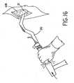
- the cupis seated in the prepared acetabulum by positioning the cup in the prepared depression, and imparting a series of blows from a mallet against the striker cap. The force of the blows is transmitted through the shaft of the impactor, to seat the cup in the prepared opening in the acetabulum.
- the surgical implement coupler of the impactoris detached from the cup.
- An acetabular cup impactoris known with a curved shaft that makes proper alignment of the tool more easily accomplished during a minimally invasive surgical procedure, and includes a remotely activated surgical implement coupler for disengaging the head from an acetabular cup.
- the surgical implement coupleris adapted for selective attachment to and detachment from an orthopedic device such as an acetabular cup.
- the surgical implement couplerincludes a threaded stud rotatably disposed in and retained by a sleeve.
- the threaded studis adapted for threaded engagement with an acetabular cup or other orthopedic device.
- a universal joint or swivel driveis disposed rotatably in the shaft assembly and is drivingly connected to the threaded stud such that rotation of the swivel drive causes rotation of the threaded stud in the sleeve.
- a thumb wheel near the handle of the impactoractuates the swivel drive.
- An acetabular cup impactor or inserteris known with a curved shaft and which encloses a drive train and which includes at a far end, a prosthesis (acetabular cup, for example) engaging collet, and at the opposite end, a knob or handle which facilitates turning of the drive train by the operator.
- a prosthesisacetabular cup, for example
- a knob or handlewhich facilitates turning of the drive train by the operator.
- knobWhen knob is turned in one direction, the prosthesis-engaging collet locks the prosthesis against rotational movement. Further, the collet action eliminates the need of threading the acetabular prosthesis on the end of the inserter as the prosthesis can simply be placed over the collet and the collet expanded so as to grip the internal threads of the prosthesis. Turning the knob in the opposite direction can release the collet from the prosthesis.
- WO 2004/010882discloses the features of the preamble of claim 1. Another inserter is known from WO 2005/049153 .
- the present inventionprovides an orthopaedic impactor with a push rod linearly displaceable within an open shaft, where the push rod is actuated within the shaft by a trigger to engage and release an implant.
- the inventioncomprises, in one form thereof, an orthopaedic implant impactor as defined by the features of claim 1.
- the inventioncomprises, in another form thereof, a method of connecting an impactor to an orthopaedic implant as defined in claim 10.
- An advantage of the present inventionis that it is easy to use in a minimally invasive surgical procedure.
- Another advantage of the present inventionis that it is time efficient for the surgeon to use, particularly with respect to engaging and disengaging the acetabular cup.
- Yet another advantage of the present inventionis that it is easy to clean and sterilize.
- Yet another advantage of the present inventionis that the impaction collar subassembly is easily removed from the impactor.
- Yet another advantage of the present inventionis that the impaction collar subassembly is easily installed onto the impactor.
- impaction collar subassemblycan be compatible with many different manufacturer's styles of acetabular cups.
- Yet another advantage of the present inventionis that impactor can be easily configured for a particular manufacturer's style of acetabular cup by simply installing the appropriate impaction collar subassembly.
- Yet another advantage of the present inventionis that manufacturing efficiencies are achieved in that the components of the impaction collar subassembly are interchangeable, and a variety of impaction collar subassemblies can be used with a single impaction tool subassembly
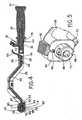
- FIG. 1there is shown an orthopaedic implant impactor 20 and an orthopaedic implant 21 shown as an acetabular cup prosthesis.
- impactor 20includes impaction tool subassembly 22 and impaction collar subassembly 24.
- Impaction tool subassembly 22includes handle subassembly 26 connected to impactor shaft 28.
- Handle subassembly 26includes a handle 29, a strikecap 30 connected to handle shaft 32, and handle shaft 32 can be fixedly connected to impactor shaft 28 using pin 34.
- Impaction tool subassembly 22further includes alignment guide subassembly 36 which is rotatable around handle shaft 32, and which can be fixed in place by tightening alignment guide lock nut 38 against washer 40 and alignment guide subassembly 36.
- Push rod 42 and cam lock lever or trigger 44are both connected to distal end 46 of impactor shaft 28 at pins 48 and 50, respectively.
- Push rod 42is biased against trigger 44 by resilient member 52, which is shown as a spring, at proximal end 54 of impactor shaft 28.
- Cam lock lever 44is pivotably connected to distal end 46 at pin 50, and includes a cam end 56 connected to push rod 42.
- Push rod 42includes slot 58 which is connected to pin 48 so that push rod 42 is linearly displaceable along shaft 28 when trigger 44 is rotated.
- Impaction tool subassembly 22further includes a shaft collar 60, and a release button 62 connected to a release pin 64, where both release button 62 and release pin 64 are biased toward the end of shaft collar 60 with a resilient member such as spring 66.
- J-slots 68, along with release button 62, release pin 64 and spring 66,facilitate a relatively easy removal and fixation of impaction collar subassembly 24 relative to impaction tool subassembly 22, as will be discussed further below.
- Push rod 42extends substantially from proximal end 54 to distal end 46, and impactor shaft 28 includes at least one aperture 70 exposing push rod 42 along a substantial length of push rod 42, which allows impactor 20 to at least be easily cleaned, sterilized and maintained. Push rod 42 extends into aperture 72 of shaft collar 60.
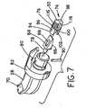
- Impaction collar subassembly 24(see particularly Figs. 4 , 6 and 7 ) is connected to push rod 42 and shaft collar 60.
- Impaction collar subassembly 24includes a threaded pair 74 held together with an O-ring 76 and a wedge 78 inserted between threaded pair 74.
- Impaction collar subassembly 24further includes a sleeve 80 and an impaction collar 82, where threaded pair 74, O-ring 76 and wedge 78 are held at least partially within impaction collar 82.
- Wedge 78includes a first wedge face 84 and a second wedge face 86 and a slot 88 extending from first wedge face 84 to second wedge face 86.
- Threaded pair 74includes a first half 92 with a first wedge end 94 which has a first hole 96 and a second half 98 with a second wedge end 100 which has a second hole 102, and pin 90 is also inserted through first hole 96 and second hole 102. Consequently, both wedge 78 and threaded pair 74 are constrained by pin 90 relative to impaction collar 82. That is, wedge 78 can move longitudinally, but not radially, relative to impaction collar 82; whereas each of first half 92 and second half 98 of threaded pair 74 can move radially, but not longitudinally, relative to impaction collar 82. ..
- Figs. 8 and 9illustrate an embodiment of acetabular cup prosthesis 21.
- the size and geometry of acetabular cup prosthesis 21can vary from manufacturer to another manufacturer, and can also vary from product line to another product line of a given manufacture.
- the size and geometry of acetabular cup prosthesis 21also is dictated by the patient whose hip is being replaced.
- Cup 21may be porous coated on their convex side to promote bone ingrowth, and may provide some method to firmly attach a poly liner which can vary among manufacturers and/or product lines.
- Cup 21can include fixation screw through holes 104 for acetabular fixation screws, and the presence, size, number and location of holes 104 can vary among manufacturers and/or product lines.
- Threaded hole 106which may or may not be a through hole, is used to connect impactor 20 with implant 21.
- the size (for example diameter and depth) and thread type (for example threads/unit length and thread standard) of threaded hole 106can vary among manufacturers and/or product lines and/or sizes of implant 21.
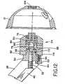
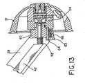
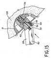
- first threaded end 116 and second threaded end 118into the threads of threaded hole 106, and thereby allows a surgeon to position and impact acetabular cup 21 into a prepared acetabulum 108 using impactor 20 ( Figs. 14-16 ).
- a reverse motion of trigger 44radially retracts first half 92 and second half 98 to disengage threaded pair 74 from threaded hole 106 and thereby release impactor 20 from acetabular cup 21.
- the size and thread type of threaded hole 106varies. Consequently, the size and thread type of threaded pair 74 (first threaded end 116 and second threaded end 118) can be varied to be compatible with different implants 21. Installing a different threaded pair 74 into impaction collar subassembly 24 can be tedious and time consuming, and generally not suitable for a surgical environment and/or surgical procedure.
- the present inventionallows for quick attachment and detachment of impaction tool subassembly 22 from impaction collar subassembly 24, and a variety of impaction collar subassemblies 24 can be available, each with a different threaded pair 74 to accommodate the different threaded holes 106 (size and thread type) of different implants 21.
- impaction collar subassembly 24is slid over shaft collar 82, the base of impaction collar 82 depresses release pin 64, and locking pins 110, 112 are inserted into J-slots 68.
- Impaction collar subassembly 24is then rotated relative to shaft collar 82, locking pins 110, 112 continue into J-slots 68, and release pin 64 is biased into release pin hole 114 of impaction collar subassembly 24, thereby locking impaction collar subassembly 24 relative to impaction tool subassembly 22.
- release button 62is depressed away from impaction collar subassembly 24, thereby releasing release pin 64 from release pin hole 114, and impaction collar subassembly 24 is rotated and then translated to release locking pins 110, 112 from J-slots 68 thereby freeing impaction collar subassembly 24 from impaction tool subassembly 22.
- impaction collar subassemblies 24can be available during surgery, or in a surgical tool kit, each having a different threaded pair 74 corresponding to a different type of implant 21.
- impaction collar subassembly 24can be easily and quickly installed onto impactor 20. Additionally, manufacturing efficiencies are achieved by the present invention in that the components of impaction collar subassembly 24 are interchangeable, and a variety of impaction collar subassemblies 24 can be used with a single impaction tool subassembly 22.
- the present inventionprovides a method of connecting an impactor 20 to an orthopaedic implant 21, including the steps of: providing impactor 20 including a shaft 28 having a proximal end 54 and a distal end 46, a trigger 44 pivotably connected to distal end 46, trigger 44 including a cam end 56, a push rod 42 within shaft 28 and connected to cam end 56 of trigger 44, and a threaded pair 74 connected to an end of push rod 42 opposite trigger 44; providing orthopaedic implant 21 including a threaded hole 106; locating threaded pair 74 within threaded hole 106; pivoting trigger 44; linearly displacing push rod 42; and radially expanding threaded pair 74 to engage threaded hole 106.
Landscapes
- Health & Medical Sciences (AREA)
- Orthopedic Medicine & Surgery (AREA)
- Transplantation (AREA)
- Heart & Thoracic Surgery (AREA)
- Cardiology (AREA)
- Oral & Maxillofacial Surgery (AREA)
- Engineering & Computer Science (AREA)
- Biomedical Technology (AREA)
- Vascular Medicine (AREA)
- Life Sciences & Earth Sciences (AREA)
- Animal Behavior & Ethology (AREA)
- General Health & Medical Sciences (AREA)
- Public Health (AREA)
- Veterinary Medicine (AREA)
- Physical Education & Sports Medicine (AREA)
- Prostheses (AREA)
Description
- The present invention relates to orthopaedic instruments, and, more particularly, to orthopaedic implant impactors.
- The hip joint is configured as a ball and socket arrangement which includes the femoral head joined to the natural socket or acetabulum located in the pelvis. Deterioration of the acetabulum and/or femoral head can be brought about by injury or progressive diseases such as osteoarthritis. When injury or disease occurs, the damaged component(s) can be replaced or rebuilt using appropriate orthopaedic implants. In the technique known as a "total hip replacement", one method involves cementing or press-fitting an acetabular cup prosthesis into the acetabulum after the acetabulum has been sufficiently reamed to accept the cup. Additionally, fixation fasteners can be used to hold the cup in the acetabulum, and the cup can include a porous coating on the convex side to promote bone ingrowth. The femoral head can also typically be replaced.
- In order to properly seat an acetabular cup into the acetabulum an impaction tool, or impactor, is used by the surgeon to firmly seat the cup. The impactor needs to securely hold the cup while the cup is being located in the acetabulum, and the impactor also needs to securely hold the cup while the cup is being impacted into the acetabulum. The acetabular cup impactor can include a surgical implement coupler which can be secured to the acetabular cup. An elongated shaft is joined to the surgical implement coupler at one end, and includes a striker cap at the opposite end of the shaft. The cup is seated in the prepared acetabulum by positioning the cup in the prepared depression, and imparting a series of blows from a mallet against the striker cap. The force of the blows is transmitted through the shaft of the impactor, to seat the cup in the prepared opening in the acetabulum. After the cup is properly seated, the surgical implement coupler of the impactor is detached from the cup.
- Particularly in a minimally invasive procedure, where a small incision is made to reduce the trauma to surrounding tissue, at least two problems occur in seating an acetabular cup. It is difficult to properly align the impactor because of anatomical features that are in the way, and disconnecting the head from the cup is more difficult with limited access to the end of the tool. Cleaning and sterilization of the impactor after surgery can also be difficult.
- An acetabular cup impactor is known with a curved shaft that makes proper alignment of the tool more easily accomplished during a minimally invasive surgical procedure, and includes a remotely activated surgical implement coupler for disengaging the head from an acetabular cup. The surgical implement coupler is adapted for selective attachment to and detachment from an orthopedic device such as an acetabular cup. The surgical implement coupler includes a threaded stud rotatably disposed in and retained by a sleeve. The threaded stud is adapted for threaded engagement with an acetabular cup or other orthopedic device. A universal joint or swivel drive is disposed rotatably in the shaft assembly and is drivingly connected to the threaded stud such that rotation of the swivel drive causes rotation of the threaded stud in the sleeve. A thumb wheel near the handle of the impactor actuates the swivel drive. A problem with this design is that it requires the threaded stud to be threaded into the acetabular cup, and this threading process can be tedious and time consuming, and can result in crossthreading the threaded stud into the acetabular cup with a resultant less than secure connection between the threaded stud and the acetabular cup. Another problem with this design is that it is substantially closed along the shaft which makes the internal components, such as the swivel drive, difficult to clean and sterilize.
- An acetabular cup impactor or inserter is known with a curved shaft and which encloses a drive train and which includes at a far end, a prosthesis (acetabular cup, for example) engaging collet, and at the opposite end, a knob or handle which facilitates turning of the drive train by the operator. When knob is turned in one direction, the prosthesis-engaging collet locks the prosthesis against rotational movement. Further, the collet action eliminates the need of threading the acetabular prosthesis on the end of the inserter as the prosthesis can simply be placed over the collet and the collet expanded so as to grip the internal threads of the prosthesis. Turning the knob in the opposite direction can release the collet from the prosthesis. Although this design eliminates the need to thread the collet into the cup, the knob is relatively far from the impactor handle, and because of the rotational movement required by the knob, releasing the cup from the impactor is a two handed operation. Further, it is largely a closed design which makes the drive train difficult to clean and sterilize.
- What is needed in the art is an orthopaedic implant impactor which is easy to use in a minimally invasive procedure, which can engage and release a prosthesis with a simple motion and which is easy to clean.
WO 2004/010882 discloses the features of the preamble of claim 1. Another inserter is known fromWO 2005/049153 .- The present invention provides an orthopaedic impactor with a push rod linearly displaceable within an open shaft, where the push rod is actuated within the shaft by a trigger to engage and release an implant.
- The invention comprises, in one form thereof, an orthopaedic implant impactor as defined by the features of claim 1.
- The invention comprises, in another form thereof, a method of connecting an impactor to an orthopaedic implant as defined in claim 10.
- An advantage of the present invention is that it is easy to use in a minimally invasive surgical procedure.
- Another advantage of the present invention is that it is time efficient for the surgeon to use, particularly with respect to engaging and disengaging the acetabular cup.
- Yet another advantage of the present invention is that it is easy to clean and sterilize.
- Yet another advantage of the present invention is that the impaction collar subassembly is easily removed from the impactor.
- Yet another advantage of the present invention is that the impaction collar subassembly is easily installed onto the impactor.
- Yet another advantage of the present invention is that the impaction collar subassembly can be compatible with many different manufacturer's styles of acetabular cups.
- Yet another advantage of the present invention is that impactor can be easily configured for a particular manufacturer's style of acetabular cup by simply installing the appropriate impaction collar subassembly.
- Yet another advantage of the present invention is that manufacturing efficiencies are achieved in that the components of the impaction collar subassembly are interchangeable, and a variety of impaction collar subassemblies can be used with a single impaction tool subassembly
- The above-mentioned and other features and advantages of this invention, and the manner of attaining them, will become more apparent and the invention will be better understood by reference to the following description of embodiments of the invention taken in conjunction with the accompanying drawings, wherein:
Fig. 1 is a perspective view of an embodiment of an orthopaedic implant impactor according to the present invention, shown in relation to an embodiment of a disengaged acetabular cup prosthesis;Fig. 2 is a top view of the impactor ofFig. 1 ;Fig. 3 is a side view of the impactor ofFig. 1 ;Fig. 4 is a cross-sectional view of the impactor ofFig. 1 taken along section line 4-4 inFig. 2 ;Fig. 5 is a fragmentary perspective end view of the impactor ofFig. 1 , shown with the impaction collar subassembly removed;Fig. 6 is a fragmentary cross-sectional side view of the end of the impactor ofFig. 1 , shown with the impaction collar subassembly prior to assembly onto the end of the impactor;Fig. 7 is a a fragmentary perspective view of the impactor ofFig. 1 , shown with the impaction collar subassembly partially exploded;Fig. 8 is an end view of the acetabular cup prosthesis ofFig. 1 ;Fig. 9 is a cross-sectional view of the acetabular cup ofFig. 1 taken along section line 9-9 inFig. 8 ;Fig. 10 is a fragmentary side view of the impactor and acetabular cup ofFig. 1 , shown prior to engaging the cup with the impactor;Fig. 11 is a fragmentary side view of the impactor and acetabular cup ofFig. 1 , shown after engaging the cup with the impactor;Fig. 12 is a fragmentary cross-sectional view of the impactor ofFig. 1 , showing particularly the impaction collar subassembly connected to the end of the impaction tool subassembly, and shown prior to engaging the cup with the impactor;Fig. 13 is a fragmentary cross-sectional view of the impactor ofFig. 12 , shown engaging the cup with the impactor;Fig. 14 is a fragmentary cross-sectional view of the impactor/acetabular cup combination ofFig. 13 , shown prior to engaging the cup in a prepared acetabulum;Fig. 15 is a fragmentary cross-sectional view of the impactor/acetabular cup combination ofFig. 13 , shown setting the cup in a prepared acetabulum;Fig. 16 is a side view of the impactor/acetabular cup combination ofFig. 13 , shown impacting the cup in a prepared acetabulum; andFig. 17 is a fragmentary cross-sectional view of the impactor/acetabular cup combination ofFig. 13 , shown after setting/impacting the cup in a prepared acetabulum, and after disengaging the cup with the impactor.- Corresponding reference characters indicate corresponding parts throughout the several views. The exemplifications set out herein illustrate one preferred embodiment of the invention, in one form, and such exemplifications are not to be construed as limiting the scope of the invention in any manner.
- Referring now to the drawings, and more particularly to
Fig. 1 , there is shown anorthopaedic implant impactor 20 and anorthopaedic implant 21 shown as an acetabular cup prosthesis. - Shown more particularly in
Figs. 2-6 ,impactor 20 includesimpaction tool subassembly 22 andimpaction collar subassembly 24.Impaction tool subassembly 22 includeshandle subassembly 26 connected toimpactor shaft 28.Handle subassembly 26 includes ahandle 29, astrikecap 30 connected to handleshaft 32, and handleshaft 32 can be fixedly connected toimpactor shaft 28 usingpin 34.Impaction tool subassembly 22 further includesalignment guide subassembly 36 which is rotatable around handleshaft 32, and which can be fixed in place by tightening alignmentguide lock nut 38 againstwasher 40 andalignment guide subassembly 36. Pushrod 42 and cam lock lever or trigger 44 are both connected todistal end 46 ofimpactor shaft 28 atpins rod 42 is biased againsttrigger 44 byresilient member 52, which is shown as a spring, atproximal end 54 ofimpactor shaft 28.Cam lock lever 44 is pivotably connected todistal end 46 atpin 50, and includes acam end 56 connected to pushrod 42. Pushrod 42 includesslot 58 which is connected to pin 48 so thatpush rod 42 is linearly displaceable alongshaft 28 whentrigger 44 is rotated.Impaction tool subassembly 22 further includes ashaft collar 60, and arelease button 62 connected to arelease pin 64, where bothrelease button 62 andrelease pin 64 are biased toward the end ofshaft collar 60 with a resilient member such asspring 66. J-slots 68, along withrelease button 62,release pin 64 andspring 66, facilitate a relatively easy removal and fixation ofimpaction collar subassembly 24 relative toimpaction tool subassembly 22, as will be discussed further below. Pushrod 42 extends substantially fromproximal end 54 todistal end 46, andimpactor shaft 28 includes at least oneaperture 70 exposingpush rod 42 along a substantial length ofpush rod 42, which allows impactor 20 to at least be easily cleaned, sterilized and maintained. Pushrod 42 extends intoaperture 72 ofshaft collar 60. - Impaction collar subassembly 24 (see particularly
Figs. 4 ,6 and7 ) is connected to pushrod 42 andshaft collar 60.Impaction collar subassembly 24 includes a threadedpair 74 held together with an O-ring 76 and awedge 78 inserted between threadedpair 74.Impaction collar subassembly 24 further includes asleeve 80 and animpaction collar 82, where threadedpair 74, O-ring 76 andwedge 78 are held at least partially withinimpaction collar 82.Wedge 78 includes afirst wedge face 84 and asecond wedge face 86 and aslot 88 extending fromfirst wedge face 84 tosecond wedge face 86. Apin 90 is inserted throughslot 88 and connected toimpaction collar 82. Threadedpair 74 includes afirst half 92 with afirst wedge end 94 which has a first hole 96 and asecond half 98 with asecond wedge end 100 which has asecond hole 102, andpin 90 is also inserted through first hole 96 andsecond hole 102. Consequently, bothwedge 78 and threadedpair 74 are constrained bypin 90 relative toimpaction collar 82. That is,wedge 78 can move longitudinally, but not radially, relative toimpaction collar 82; whereas each offirst half 92 andsecond half 98 of threadedpair 74 can move radially, but not longitudinally, relative toimpaction collar 82. .. Figs. 8 and 9 illustrate an embodiment ofacetabular cup prosthesis 21. The size and geometry ofacetabular cup prosthesis 21 can vary from manufacturer to another manufacturer, and can also vary from product line to another product line of a given manufacture. The size and geometry ofacetabular cup prosthesis 21 also is dictated by the patient whose hip is being replaced.Cup 21 may be porous coated on their convex side to promote bone ingrowth, and may provide some method to firmly attach a poly liner which can vary among manufacturers and/or product lines.Cup 21 can include fixation screw throughholes 104 for acetabular fixation screws, and the presence, size, number and location ofholes 104 can vary among manufacturers and/or product lines. Threadedhole 106, which may or may not be a through hole, is used to connect impactor 20 withimplant 21. The size (for example diameter and depth) and thread type (for example threads/unit length and thread standard) of threadedhole 106 can vary among manufacturers and/or product lines and/or sizes ofimplant 21.- As shown particularly in
Figs. 10-13 , when cam locklever 44 is pivoted and linearly displacespush rod 42,push rod 42 presses againstwedge 78 to movewedge 78 towards the longitudinally fixed threadedpair 74, and radially expandsfirst half 92 andsecond half 98 against O-ring 76. When threadedpair 74 is within threadedhole 106 ofimplant 21, and threadedpair 74 is actuated to radially expand within threadedhole 106, threadedpair 74 engages threaded hole 106 (Fig. 13 ), by engaging first threadedend 116 and second threadedend 118 into the threads of threadedhole 106, and thereby allows a surgeon to position and impactacetabular cup 21 into aprepared acetabulum 108 using impactor 20 (Figs. 14-16 ). A reverse motion oftrigger 44 radially retractsfirst half 92 andsecond half 98 to disengage threadedpair 74 from threadedhole 106 and thereby release impactor 20 fromacetabular cup 21. - As previously discussed, the size and thread type of threaded
hole 106 varies. Consequently, the size and thread type of threaded pair 74 (first threadedend 116 and second threaded end 118) can be varied to be compatible withdifferent implants 21. Installing a different threadedpair 74 intoimpaction collar subassembly 24 can be tedious and time consuming, and generally not suitable for a surgical environment and/or surgical procedure. Instead, the present invention allows for quick attachment and detachment ofimpaction tool subassembly 22 fromimpaction collar subassembly 24, and a variety ofimpaction collar subassemblies 24 can be available, each with a different threadedpair 74 to accommodate the different threaded holes 106 (size and thread type) ofdifferent implants 21. Whenimpaction collar subassembly 24 is slid overshaft collar 82, the base ofimpaction collar 82 depressesrelease pin 64, and lockingpins slots 68.Impaction collar subassembly 24 is then rotated relative toshaft collar 82, locking pins 110, 112 continue into J-slots 68, andrelease pin 64 is biased intorelease pin hole 114 ofimpaction collar subassembly 24, thereby lockingimpaction collar subassembly 24 relative toimpaction tool subassembly 22. To releaseimpaction collar subassembly 24 fromimpaction tool subassembly 22,release button 62 is depressed away fromimpaction collar subassembly 24, thereby releasingrelease pin 64 fromrelease pin hole 114, andimpaction collar subassembly 24 is rotated and then translated to release lockingpins slots 68 thereby freeingimpaction collar subassembly 24 fromimpaction tool subassembly 22. In this way a variety ofimpaction collar subassemblies 24 can be available during surgery, or in a surgical tool kit, each having a different threadedpair 74 corresponding to a different type ofimplant 21. Once animplant 21 is selected, a correspondingimpaction collar subassembly 24 can be easily and quickly installed ontoimpactor 20. Additionally, manufacturing efficiencies are achieved by the present invention in that the components ofimpaction collar subassembly 24 are interchangeable, and a variety ofimpaction collar subassemblies 24 can be used with a singleimpaction tool subassembly 22. - In use, the present invention provides a method of connecting an impactor 20 to an
orthopaedic implant 21, including the steps of: providingimpactor 20 including ashaft 28 having aproximal end 54 and adistal end 46, atrigger 44 pivotably connected todistal end 46, trigger 44 including acam end 56, apush rod 42 withinshaft 28 and connected to cam end 56 oftrigger 44, and a threadedpair 74 connected to an end ofpush rod 42opposite trigger 44; providingorthopaedic implant 21 including a threadedhole 106; locating threadedpair 74 within threadedhole 106; pivotingtrigger 44; linearly displacingpush rod 42; and radially expanding threadedpair 74 to engage threadedhole 106. - While this invention has been described as having a preferred design, the present invention can be further modified within the scope of the claims.
Claims (10)
- An orthopaedic implant impactor
Including a shaft (28) having a proximal end (54) and a distal end (46); wherein
the orthopaedic implant impactor comprises
a trigger (44) pivotably connected to said distal end (46), said trigger (44) including a cam end (56);
a push rod (42) within said shaft (28) and connected to said cam end (56), said push rod (42) being linearly displaceable along said shaft (28), when said trigger (44) is rotated;
a nonthreaded wedge (78) associated with said push rod (42),
characterized in that said wedge (78) includes a first wedge face (84), a second wedge face (86), and a slot (88) extending from said first wedge face (84) to said second wedge face (86), and furthercharacterized in that the impactor comprises:an impaction collar subassembly (24) connected to said push rod (42), said impaction collar subassembly (24) including an impaction collar (82) and a threaded pair (74), said wedge (78) being inserted between said threaded pair /74), said threaded pair (74) and said wedge (78) being held at least partially within said impaction collar (82),said threaded pair (74) including a first half (92) with a first wedge end (94) which has a first hole (96) and a second half (98) with a second wedge end (100) which has a second hole (102), said wedge (78) expanding said first half (92) and said second half (98) relative to one another when said push rod (42) pushes said wedge (78), said impaction collar subassembly (24) further including a coupling pin (90) inserted through said first hole (96), said second hole (102), and said slot (88) and connected to said impaction collar (82). - The orthopaedic implant impactor of claim 1, wherein said threaded pair (74) being held together with an O-ring, said O-ring being held at least partially within said impaction collar (82).
- The orthopaedic implant impactor of at least one of the claims 1 to 2, further including a shaft collar (60) connected to said proximal end (54) of said shaft, and a release button connected to a release pin (64), where both said release button and said release pin (64) are connected to and biased toward an end of said shaft collar (82) with a resilient member, said impaction collar subassembly including a release pin hole (114) engageable with said release pin to lock said impaction collar subassembly (24) to said shaft collar.
- An orthopaedic implant impactor according to claim 1,
wherein said push rod extends substantially from said proximal end (54) to said distal end (46) and said shaft (28) includes an aperture exposing said push rod (42) along a substantial length of said push rod. - The orthopaedic implant impactor of claim 4, wherein said threaded pair (74) is held together with an O-ring.
- The orthopaedic implant impactor of claim 5, wherein said O-ring being held at least partially within said impaction collar (82).
- The orthopaedic implant impactor of claim 6, wherein said impaction collar subassembly (24) further includes a pin (90) inserted through said slot (88) and connected to said impaction collar (82).
- The orthopaedic implant of claim 6, wherein said impaction collar subassembly (24) further includes a pin inserted through said first hole and said second hole and connected to said impaction collar (82).
- The orthopaedic implant impactor of claim 5, further including a shaft collar connected to said proximal end (54) of said shaft, and a release button connected to a release pin (90), where both said release button and said release pin (90) are connected to and biased toward an end of said shaft collar (60) with a resilient
member, said impaction collar subassembly (24) including a release pin hole engageable with said release pin (90) to lock said impaction collar subassembly (24) to said shaft collar. - A method of connecting an impactor to an orthopaedic implant comprising the steps of:- providing said impactor including
a shaft (28) having a proximal end (54) and a distal end (46);
a trigger (44) pivotably connected to said distal end (46), said trigger (44) including a cam end (56);
a push rod (42) within said shaft (28) and connected to said cam end (56), said push rod (42) being linearly displaceable along said shaft (28), when said trigger (44) is rotated;
a nonthreaded wedge (78) associated with said push rod (42), said wedge (78) including a first wedge face (84), a second wedge face (86), and a slot (88) extending from said first wedge face (84), a second wedge face (8t3), and an impaction collar subassembly (24) connected to said push rod (42), said impaction collar subassembly (24) including an impaction collar (82) and a threaded pair (74), connected to an end of said push rod opposite said trigger, said wedge (78) being inserted between said threaded pair (74), said threaded pair (74) and said wedge (78) being held at least partially within said impaction collar (82), said threaded pair (74) including a first half (92) with a first wedge end (94) which has a first hole (96) and a second half (98) with a second wedge end (100) which has a second hole (102), said wedge (78) expanding said first half (92) and said second half (98) relative to one another when said push rod (42) pushes said wedge (78), said impaction collar subassembly (24) further including a coupling pin (90) inserted through said first hole (96), said second hole (102), and said slot (88) and connected to said impaction collar (82);- providing the orthopaedic implant including a threaded hole;- locating said threaded pair within said threaded hole;- pivoting said trigger (44);- linearly displacing said push rod (42); and- radially expanding said threaded pair (74) to engage said threaded hole.
Priority Applications (1)
| Application Number | Priority Date | Filing Date | Title |
|---|---|---|---|
| EP11007915AEP2401988A1 (en) | 2006-01-25 | 2007-01-19 | Split thread orthopaedic implant impactor |
Applications Claiming Priority (1)
| Application Number | Priority Date | Filing Date | Title |
|---|---|---|---|
| US11/339,130US7621921B2 (en) | 2006-01-25 | 2006-01-25 | Split thread orthopaedic implant impactor |
Related Child Applications (1)
| Application Number | Title | Priority Date | Filing Date |
|---|---|---|---|
| EP11007915.9Division-Into | 2011-09-29 |
Publications (2)
| Publication Number | Publication Date |
|---|---|
| EP1813229A1 EP1813229A1 (en) | 2007-08-01 |
| EP1813229B1true EP1813229B1 (en) | 2012-08-08 |
Family
ID=37964641
Family Applications (2)
| Application Number | Title | Priority Date | Filing Date |
|---|---|---|---|
| EP07001139AActiveEP1813229B1 (en) | 2006-01-25 | 2007-01-19 | Split thread orthopaedic implant impactor |
| EP11007915AWithdrawnEP2401988A1 (en) | 2006-01-25 | 2007-01-19 | Split thread orthopaedic implant impactor |
Family Applications After (1)
| Application Number | Title | Priority Date | Filing Date |
|---|---|---|---|
| EP11007915AWithdrawnEP2401988A1 (en) | 2006-01-25 | 2007-01-19 | Split thread orthopaedic implant impactor |
Country Status (3)
| Country | Link |
|---|---|
| US (2) | US7621921B2 (en) |
| EP (2) | EP1813229B1 (en) |
| ES (1) | ES2392268T3 (en) |
Families Citing this family (67)
| Publication number | Priority date | Publication date | Assignee | Title |
|---|---|---|---|---|
| US7651501B2 (en)* | 2004-03-05 | 2010-01-26 | Wright Medical Technology, Inc. | Instrument for use in minimally invasive hip surgery |
| US8277457B1 (en) | 2004-12-09 | 2012-10-02 | Greatbatch Medical S.A. | Orthopaedic inserter using a collet mechanism |
| US7682363B2 (en)* | 2004-12-09 | 2010-03-23 | Greatbatch Medical S.A. | Inserter for minimally invasive joint surgery |
| US7621921B2 (en) | 2006-01-25 | 2009-11-24 | Symmetry Medical, Inc | Split thread orthopaedic implant impactor |
| DE102007020484A1 (en) | 2006-05-01 | 2007-12-13 | Precimed S.A. | Insertion instrument for minimally invasive joint surgery with exchangeable thread |
| GB0617484D0 (en)* | 2006-09-05 | 2006-10-18 | Comis Orthopaedics Ltd | Surgical apparatus |
| US8556897B2 (en)* | 2007-02-09 | 2013-10-15 | Christopher G. Sidebotham | Modular spherical hollow reamer assembly for medical applications |
| US8435244B2 (en) | 2007-05-02 | 2013-05-07 | Zimmer, Inc. | Orthopedic tool for altering the connection between orthopedic components |
| US20090099566A1 (en)* | 2007-10-10 | 2009-04-16 | Maness Megan A | Modular stem inserter |
| DE102008022329B4 (en)* | 2008-04-29 | 2014-05-15 | Aesculap Ag | Acetabulum and handling system for an acetabular cup |
| GB0808284D0 (en) | 2008-05-07 | 2008-06-11 | Benoist Girard Sas | |
| US8398650B1 (en) | 2009-01-27 | 2013-03-19 | Greatbatch Medical S.A. | Offset cup impactor with an expandable dome for double mobility implants |
| US8998997B2 (en) | 2009-08-11 | 2015-04-07 | Michael D. Ries | Implantable mobile bearing prosthetics |
| US9095453B2 (en) | 2009-08-11 | 2015-08-04 | Michael D. Ries | Position adjustable trial systems for prosthetic implants |
| US8496666B2 (en)* | 2009-08-11 | 2013-07-30 | Imds Corporation | Instrumentation for mobile bearing prosthetics |
| US8430886B2 (en)* | 2010-01-25 | 2013-04-30 | Howmedica Osteonics Corp. | Inserter for locating and impacting an acetabular cup |
| EP2347736B1 (en)* | 2010-01-25 | 2013-01-16 | Benoist Girard Sas | Inserter for locating and impacting an acetabular cup |
| GB201001985D0 (en) | 2010-02-05 | 2010-03-24 | Materialise Nv | Guiding instruments and impactors for an acetabular cup implant, combinations therof, methods for manufacturing and uses thereof |
| US8758360B2 (en) | 2010-06-02 | 2014-06-24 | Microport Orthopedics Holdings Inc. | Modular impactor head |
| EP2422754B1 (en) | 2010-08-27 | 2014-11-05 | Greatbatch Medical SA | Offset cup impactor with a grasping plate for double mobility implants |
| GB201020041D0 (en) | 2010-11-25 | 2011-01-12 | Benoist Girard & Cie | Prosthetic acetabular cup inserter and impactor |
| GB201020040D0 (en)* | 2010-11-25 | 2011-01-12 | Benoist Girard & Cie | Prosthetic acetabular cup inserter and impactor |
| AU2012204462A1 (en) | 2011-01-05 | 2013-07-11 | Hospira, Inc. | Spray drying vancomycin |
| EP2476397B1 (en) | 2011-01-17 | 2015-10-21 | Greatbatch Medical SA | Straight cup impactor with lever arm |
| US9119731B2 (en) | 2011-01-17 | 2015-09-01 | Greatbach Medical S.A. | Straight cup impactor |
| CA2834937A1 (en)* | 2011-05-03 | 2012-11-08 | Smith & Nephew, Inc. | Patient-matched guides for orthopedic implants |
| US9028502B2 (en)* | 2011-09-23 | 2015-05-12 | Greatbatch Medical S.A. | Ceramic implant holder |
| US8900245B2 (en)* | 2012-06-07 | 2014-12-02 | Howmedica Osteonics Corp. | Glenosphere inserter and impactor |
| US9241811B2 (en) | 2012-09-14 | 2016-01-26 | Biomet Manufacturing, Llc | Method and apparatus for implanting a prosthesis |
| US9439780B2 (en) | 2012-09-14 | 2016-09-13 | Biomet Manufacturing, Llc | Acetabular cup inserter handle |
| TW201412281A (en)* | 2012-09-18 | 2014-04-01 | United Orthopedic Corp | Acetabular cup implanting device |
| US9763806B2 (en)* | 2012-10-23 | 2017-09-19 | Biomet Manufacturing, Llc | Method and apparatus for implanting a prosthesis |
| US9456828B2 (en)* | 2013-01-18 | 2016-10-04 | Symmetry Medical Manufacturing, Inc. | Medical instrument handle |
| US20140228854A1 (en)* | 2013-02-08 | 2014-08-14 | Biomet Manufacturing Corporation | Apparatus And Method For Positioning A Prosthesis |
| CN104043104B (en) | 2013-03-15 | 2018-07-10 | 浙江创新生物有限公司 | The spray dried powder and its industrialized process for preparing of hydrochloric vancomycin |
| FR3004331B1 (en)* | 2013-04-11 | 2015-04-17 | Maurice Marle Ets | REMOVABLE HAND WITH A DISMANTLING ASSEMBLY DEVICE |
| US9345585B2 (en)* | 2013-10-08 | 2016-05-24 | Howmedica Osteonics Corp. | Acetabular cup insertion instruments |
| GB201322237D0 (en) | 2013-12-16 | 2014-01-29 | Depuy Ireland Ltd | Surgical reamer |
| JP6407619B2 (en)* | 2014-08-11 | 2018-10-17 | 京セラ株式会社 | Grip and shell positioner for prosthetic surgical instruments |
| US10092304B2 (en) | 2014-09-30 | 2018-10-09 | Depuy Ireland Unlimited Company | Orthopaedic surgical instrument assembly for reaming a patient's acetabulum |
| US9675364B2 (en) | 2014-09-30 | 2017-06-13 | Depuy Ireland Unlimited Company | Grater and trial liner |
| US10543003B2 (en) | 2014-09-30 | 2020-01-28 | Depuy Ireland Unlimited Company | Orthopaedic surgical instrument assembly and method of manufacturing same |
| US10624763B2 (en)* | 2014-10-10 | 2020-04-21 | Symmetry Medical Manufacturing, Inc. | Orthopaedic impactor with radially expanding threading |
| FR3028174B1 (en)* | 2014-11-07 | 2022-07-01 | Dedienne Sante | SET FOR IMPLANTING A CUP |
| US20160135862A1 (en)* | 2014-11-17 | 2016-05-19 | Spinal Elements, Inc. | Curved surgical tools |
| US10092420B2 (en)* | 2014-11-19 | 2018-10-09 | Symmetry Medical Manufacturing Inc. | Method of attachment of implantable cup to a cup impactor |
| EP3111897B1 (en) | 2015-07-02 | 2018-11-14 | Greatbatch Ltd. | Orthopedic impactor |
| US10470896B2 (en)* | 2015-07-27 | 2019-11-12 | Ren-Hong Huang | Surgical inserter |
| CN106983587B (en)* | 2016-01-20 | 2019-03-15 | 北京纳通科技集团有限公司 | Using prosthesis instrument |
| AU2018279732B2 (en) | 2017-06-09 | 2024-03-07 | Mako Surgical Corp. | Systems and tools for positioning workpieces with surgical robots |
| CA3116744A1 (en) | 2017-07-05 | 2019-01-10 | Wright Medical Technology, Inc. | Anterior ankle approach system and method |
| US10828173B2 (en)* | 2017-09-14 | 2020-11-10 | Depuy Ireland Unlimited Company | Orthopaedic surgical instrument system and method for detaching trial construct assemblies |
| US20210330476A1 (en)* | 2018-03-01 | 2021-10-28 | Alden Kris | Prosthetic componenet extractor |
| DE102018125190B4 (en)* | 2018-10-11 | 2021-09-02 | Endocon Gmbh | Impact instrument for joining prosthetic implants |
| BE1027082B1 (en)* | 2019-02-27 | 2020-09-21 | Zimmer Inc | Tool for clearing a carpal bone |
| US20220331116A1 (en)* | 2019-09-11 | 2022-10-20 | Cedars-Sinai Medical Center | Apparatus and method for forming a custom cement-on-cement articulating hip spacer |
| US11166754B2 (en) | 2019-09-18 | 2021-11-09 | DePuy Synthes Products, Inc. | Strike instrument for intramedullary nail |
| US20230172730A1 (en)* | 2020-04-20 | 2023-06-08 | Howmedica Osteonics Corp. | Inserter for glenosphere |
| CN111329555B (en)* | 2020-05-19 | 2020-08-07 | 上海龙慧医疗科技有限公司 | Gear type universal shaft connection anti-blocking acetabular bone rasp and cup placing self-locking mechanism rod |
| GB202010525D0 (en)* | 2020-07-09 | 2020-08-26 | Embody Orthopaedic Ltd | Improved holder for an acetabular cup implant |
| US12011199B2 (en) | 2020-10-15 | 2024-06-18 | DePuy Synthes Products, Inc. | Bone plate, bone plate system, and method of using the same |
| CN112315630B (en)* | 2020-11-18 | 2024-11-26 | 天衍医疗器材有限公司 | A hip joint acetabular cup holder |
| US11806029B2 (en) | 2021-01-06 | 2023-11-07 | DePuy Synthes Products, Inc. | Locking trocar and method of using the same |
| US11090163B1 (en)* | 2021-01-09 | 2021-08-17 | Zafer Termanini | Interlocking reverse hip prosthesis with removable tapered central post |
| US12011203B2 (en)* | 2021-05-07 | 2024-06-18 | DePuy Synthes Products, Inc. | Offset acetabular shell impactor adapter |
| FR3136961A1 (en)* | 2022-06-22 | 2023-12-29 | Euros | Instrument for manipulating and impacting a hip prosthesis cup |
| USD1081993S1 (en)* | 2023-01-27 | 2025-07-01 | Forma Medical, Inc. | Bone fixation guide |
Citations (1)
| Publication number | Priority date | Publication date | Assignee | Title |
|---|---|---|---|---|
| WO2004010882A1 (en)* | 2002-07-25 | 2004-02-05 | Enztec Limited | Surgical impactor with workpiece engageable head |
Family Cites Families (40)
| Publication number | Priority date | Publication date | Assignee | Title |
|---|---|---|---|---|
| US4632111A (en) | 1985-03-21 | 1986-12-30 | Minnesota Mining And Manufacturing Company | Acetabular cup positioning apparatus |
| US5089003A (en) | 1989-12-22 | 1992-02-18 | Zimmer, Inc. | Rasp tool including detachable handle member |
| US5061270A (en) | 1991-03-18 | 1991-10-29 | Aboczky Robert I | System for orienting, inserting and impacting an acetabular cup prosthesis |
| GB9121132D0 (en) | 1991-10-04 | 1991-11-13 | Johnson & Johnson Orthopaedics | An acetabular cup inserter |
| US5169399A (en) | 1991-10-17 | 1992-12-08 | Boehringer Mannheim Corporation | Acetabular cup impactor |
| US5540697A (en)* | 1993-02-12 | 1996-07-30 | U.S. Medical Products, Inc. | Prosthetic socket installation apparatus and method |
| US5584837A (en)* | 1993-08-13 | 1996-12-17 | Petersen; Thomas D. | Acetabular cup inserter for orthopedic |
| DE4332872C1 (en)* | 1993-09-27 | 1995-04-06 | Zsolt Szabo | Removal tool for joint prostheses |
| US5954727A (en) | 1993-10-29 | 1999-09-21 | Howmedica Inc. | Acetabular cup positioning tool and method of positioning an acetabular cup |
| US5431657A (en) | 1994-05-23 | 1995-07-11 | Zimmer, Inc. | Instrument for installing an acetabular cup assembly |
| US5486181A (en) | 1994-08-04 | 1996-01-23 | Implex Corporation | Acetabular cup, method and tool and installing the same |
| US5800546A (en)* | 1995-08-14 | 1998-09-01 | Smith & Nephew, Inc. | Impactor apparatus for assembling modular orthopedic prosthesis components |
| US5683399A (en) | 1995-12-01 | 1997-11-04 | Stelkast Incorporated | Acetabular cup insertion tool |
| US5849015A (en)* | 1997-09-11 | 1998-12-15 | Bristol-Myers Squibb Company | Orthopaedic stem inserter with quick release lever and ratchet |
| GB9804281D0 (en) | 1998-02-27 | 1998-04-22 | Johnson & Johnson Medical Ltd | Handle assembly |
| GB9804473D0 (en) | 1998-03-02 | 1998-04-29 | Benoist Girard & Cie | Prosthesis inserter |
| US6113605A (en)* | 1998-03-02 | 2000-09-05 | Benoist Girard & Cie | Prosthesis inserter |
| JP2002537897A (en) | 1999-03-03 | 2002-11-12 | スミス アンド ネフュー インコーポレーテッド | Methods, systems and devices for inserting prosthetic implants |
| US6238435B1 (en)* | 2000-03-10 | 2001-05-29 | Bristol-Myers Squibb Co | Assembly tool for prosthetic implant |
| US6395005B1 (en)* | 2000-04-14 | 2002-05-28 | Howmedica Osteonics Corp. | Acetabular alignment apparatus and method |
| JP4384498B2 (en) | 2002-02-08 | 2009-12-16 | チャナ,ガーシャラン,シン | Improved surgical device and method of use |
| US7037311B2 (en) | 2002-07-12 | 2006-05-02 | Zimmer Technology, Inc. | Tool for gripping an orthopedic implant |
| US6743235B2 (en) | 2002-10-15 | 2004-06-01 | Goli V. Subba Rao | Modular instrument for positioning acetabular prosthetic socket |
| US7004946B2 (en) | 2002-10-30 | 2006-02-28 | Symmetry Medical, Inc. | Acetabular cup impactor |
| US20050038443A1 (en)* | 2002-12-12 | 2005-02-17 | Hedley Anthony K. | Surgical tools for joint replacement |
| FR2850010B1 (en)* | 2003-01-17 | 2005-12-02 | Tornier Sa | ANCILLARY FOR THE INSTALLATION OF A PROTHETIC COTYL FOR A HIP PROSTHESIS |
| US7247158B2 (en)* | 2003-02-04 | 2007-07-24 | Wright Medical Technology, Inc. | Acetabular impactor |
| GB0307648D0 (en) | 2003-04-02 | 2003-05-07 | Benoist Girard Sas | Greater trochanter re-attachment device |
| US7037310B2 (en)* | 2003-10-21 | 2006-05-02 | Wright Medical Technology Inc | Acetabular impactor |
| EP1691733B1 (en) | 2003-11-10 | 2008-04-23 | Precimed S.A. | Inserter for minimally invasive joint surgery |
| US20050149047A1 (en)* | 2004-01-05 | 2005-07-07 | Paramount Medical Instruments, L.L.C. | Method of attaching an implant to an impactor |
| US20050187562A1 (en)* | 2004-02-03 | 2005-08-25 | Grimm James E. | Orthopaedic component inserter for use with a surgical navigation system |
| GB0405059D0 (en) | 2004-03-05 | 2004-04-07 | Benoist Girard Sas | Prosthetic acetabular cup inserter |
| DE102004042183A1 (en)* | 2004-06-22 | 2006-01-19 | Plus Endoprothetik Ag | Device for setting or removing joints or joint sockets |
| FR2876278B1 (en) | 2004-10-13 | 2007-10-26 | Thomas Gradel | COTYL APPLICATION INSTRUMENTS |
| GB0426385D0 (en) | 2004-12-01 | 2005-01-05 | Benoist Girard Sas | Prosthetic implanatation inserter for a flexible acetabular cup |
| US7682363B2 (en) | 2004-12-09 | 2010-03-23 | Greatbatch Medical S.A. | Inserter for minimally invasive joint surgery |
| US7976548B2 (en) | 2005-08-24 | 2011-07-12 | Greatbatch Medical S.A. | Surgical tool holder for facilitated sterilization |
| US7621921B2 (en)* | 2006-01-25 | 2009-11-24 | Symmetry Medical, Inc | Split thread orthopaedic implant impactor |
| DE102007020484A1 (en) | 2006-05-01 | 2007-12-13 | Precimed S.A. | Insertion instrument for minimally invasive joint surgery with exchangeable thread |
- 2006
- 2006-01-25USUS11/339,130patent/US7621921B2/ennot_activeExpired - Fee Related
- 2007
- 2007-01-19ESES07001139Tpatent/ES2392268T3/enactiveActive
- 2007-01-19EPEP07001139Apatent/EP1813229B1/enactiveActive
- 2007-01-19EPEP11007915Apatent/EP2401988A1/ennot_activeWithdrawn
- 2009
- 2009-11-02USUS12/610,439patent/US8142439B2/ennot_activeExpired - Fee Related
Patent Citations (1)
| Publication number | Priority date | Publication date | Assignee | Title |
|---|---|---|---|---|
| WO2004010882A1 (en)* | 2002-07-25 | 2004-02-05 | Enztec Limited | Surgical impactor with workpiece engageable head |
Also Published As
| Publication number | Publication date |
|---|---|
| US8142439B2 (en) | 2012-03-27 |
| EP1813229A1 (en) | 2007-08-01 |
| EP2401988A1 (en) | 2012-01-04 |
| US7621921B2 (en) | 2009-11-24 |
| ES2392268T3 (en) | 2012-12-07 |
| US20070173856A1 (en) | 2007-07-26 |
| US20100049257A1 (en) | 2010-02-25 |
Similar Documents
| Publication | Publication Date | Title |
|---|---|---|
| EP1813229B1 (en) | Split thread orthopaedic implant impactor | |
| US10772730B2 (en) | Finishing rasp and orthopaedic surgical procedure for using the same to implant a revision hip prosthesis | |
| US7682363B2 (en) | Inserter for minimally invasive joint surgery | |
| US8277457B1 (en) | Orthopaedic inserter using a collet mechanism | |
| EP2022449B1 (en) | Inserter for minimally invasive joint surgery | |
| US20070233134A1 (en) | Compound offset handle | |
| JP2024515330A (en) | Trial Components and Methods |
Legal Events
| Date | Code | Title | Description |
|---|---|---|---|
| PUAI | Public reference made under article 153(3) epc to a published international application that has entered the european phase | Free format text:ORIGINAL CODE: 0009012 | |
| AK | Designated contracting states | Kind code of ref document:A1 Designated state(s):AT BE BG CH CY CZ DE DK EE ES FI FR GB GR HU IE IS IT LI LT LU LV MC NL PL PT RO SE SI SK TR | |
| AX | Request for extension of the european patent | Extension state:AL BA HR MK YU | |
| RIN1 | Information on inventor provided before grant (corrected) | Inventor name:PARKER, BRAD, A. | |
| 17P | Request for examination filed | Effective date:20071023 | |
| AKX | Designation fees paid | Designated state(s):AT BE BG CH CY CZ DE DK EE ES FI FR GB GR HU IE IS IT LI LT LU LV MC NL PL PT RO SE SI SK TR | |
| AXX | Extension fees paid | Extension state:BA Payment date:20070216 Extension state:HR Payment date:20070216 Extension state:MK Payment date:20070216 Extension state:RS Payment date:20070216 Extension state:AL Payment date:20070216 | |
| 17Q | First examination report despatched | Effective date:20091001 | |
| GRAP | Despatch of communication of intention to grant a patent | Free format text:ORIGINAL CODE: EPIDOSNIGR1 | |
| GRAS | Grant fee paid | Free format text:ORIGINAL CODE: EPIDOSNIGR3 | |
| GRAA | (expected) grant | Free format text:ORIGINAL CODE: 0009210 | |
| AK | Designated contracting states | Kind code of ref document:B1 Designated state(s):AT BE BG CH CY CZ DE DK EE ES FI FR GB GR HU IE IS IT LI LT LU LV MC NL PL PT RO SE SI SK TR | |
| AX | Request for extension of the european patent | Extension state:AL BA HR MK RS | |
| REG | Reference to a national code | Ref country code:GB Ref legal event code:FG4D | |
| REG | Reference to a national code | Ref country code:CH Ref legal event code:EP Ref country code:AT Ref legal event code:REF Ref document number:569323 Country of ref document:AT Kind code of ref document:T Effective date:20120815 | |
| REG | Reference to a national code | Ref country code:IE Ref legal event code:FG4D | |
| REG | Reference to a national code | Ref country code:DE Ref legal event code:R096 Ref document number:602007024472 Country of ref document:DE Effective date:20121011 | |
| REG | Reference to a national code | Ref country code:ES Ref legal event code:FG2A Ref document number:2392268 Country of ref document:ES Kind code of ref document:T3 Effective date:20121207 | |
| REG | Reference to a national code | Ref country code:NL Ref legal event code:VDEP Effective date:20120808 | |
| REG | Reference to a national code | Ref country code:AT Ref legal event code:MK05 Ref document number:569323 Country of ref document:AT Kind code of ref document:T Effective date:20120808 | |
| REG | Reference to a national code | Ref country code:LT Ref legal event code:MG4D Effective date:20120808 | |
| PG25 | Lapsed in a contracting state [announced via postgrant information from national office to epo] | Ref country code:LT Free format text:LAPSE BECAUSE OF FAILURE TO SUBMIT A TRANSLATION OF THE DESCRIPTION OR TO PAY THE FEE WITHIN THE PRESCRIBED TIME-LIMIT Effective date:20120808 Ref country code:IS Free format text:LAPSE BECAUSE OF FAILURE TO SUBMIT A TRANSLATION OF THE DESCRIPTION OR TO PAY THE FEE WITHIN THE PRESCRIBED TIME-LIMIT Effective date:20121208 Ref country code:CY Free format text:LAPSE BECAUSE OF FAILURE TO SUBMIT A TRANSLATION OF THE DESCRIPTION OR TO PAY THE FEE WITHIN THE PRESCRIBED TIME-LIMIT Effective date:20120808 Ref country code:AT Free format text:LAPSE BECAUSE OF FAILURE TO SUBMIT A TRANSLATION OF THE DESCRIPTION OR TO PAY THE FEE WITHIN THE PRESCRIBED TIME-LIMIT Effective date:20120808 Ref country code:FI Free format text:LAPSE BECAUSE OF FAILURE TO SUBMIT A TRANSLATION OF THE DESCRIPTION OR TO PAY THE FEE WITHIN THE PRESCRIBED TIME-LIMIT Effective date:20120808 | |
| PG25 | Lapsed in a contracting state [announced via postgrant information from national office to epo] | Ref country code:SE Free format text:LAPSE BECAUSE OF FAILURE TO SUBMIT A TRANSLATION OF THE DESCRIPTION OR TO PAY THE FEE WITHIN THE PRESCRIBED TIME-LIMIT Effective date:20120808 Ref country code:SI Free format text:LAPSE BECAUSE OF FAILURE TO SUBMIT A TRANSLATION OF THE DESCRIPTION OR TO PAY THE FEE WITHIN THE PRESCRIBED TIME-LIMIT Effective date:20120808 Ref country code:GR Free format text:LAPSE BECAUSE OF FAILURE TO SUBMIT A TRANSLATION OF THE DESCRIPTION OR TO PAY THE FEE WITHIN THE PRESCRIBED TIME-LIMIT Effective date:20121109 Ref country code:LV Free format text:LAPSE BECAUSE OF FAILURE TO SUBMIT A TRANSLATION OF THE DESCRIPTION OR TO PAY THE FEE WITHIN THE PRESCRIBED TIME-LIMIT Effective date:20120808 Ref country code:PT Free format text:LAPSE BECAUSE OF FAILURE TO SUBMIT A TRANSLATION OF THE DESCRIPTION OR TO PAY THE FEE WITHIN THE PRESCRIBED TIME-LIMIT Effective date:20121210 Ref country code:PL Free format text:LAPSE BECAUSE OF FAILURE TO SUBMIT A TRANSLATION OF THE DESCRIPTION OR TO PAY THE FEE WITHIN THE PRESCRIBED TIME-LIMIT Effective date:20120808 Ref country code:BE Free format text:LAPSE BECAUSE OF FAILURE TO SUBMIT A TRANSLATION OF THE DESCRIPTION OR TO PAY THE FEE WITHIN THE PRESCRIBED TIME-LIMIT Effective date:20120808 | |
| PG25 | Lapsed in a contracting state [announced via postgrant information from national office to epo] | Ref country code:NL Free format text:LAPSE BECAUSE OF FAILURE TO SUBMIT A TRANSLATION OF THE DESCRIPTION OR TO PAY THE FEE WITHIN THE PRESCRIBED TIME-LIMIT Effective date:20120808 | |
| PG25 | Lapsed in a contracting state [announced via postgrant information from national office to epo] | Ref country code:RO Free format text:LAPSE BECAUSE OF FAILURE TO SUBMIT A TRANSLATION OF THE DESCRIPTION OR TO PAY THE FEE WITHIN THE PRESCRIBED TIME-LIMIT Effective date:20120808 Ref country code:DK Free format text:LAPSE BECAUSE OF FAILURE TO SUBMIT A TRANSLATION OF THE DESCRIPTION OR TO PAY THE FEE WITHIN THE PRESCRIBED TIME-LIMIT Effective date:20120808 Ref country code:EE Free format text:LAPSE BECAUSE OF FAILURE TO SUBMIT A TRANSLATION OF THE DESCRIPTION OR TO PAY THE FEE WITHIN THE PRESCRIBED TIME-LIMIT Effective date:20120808 Ref country code:CZ Free format text:LAPSE BECAUSE OF FAILURE TO SUBMIT A TRANSLATION OF THE DESCRIPTION OR TO PAY THE FEE WITHIN THE PRESCRIBED TIME-LIMIT Effective date:20120808 | |
| REG | Reference to a national code | Ref country code:CH Ref legal event code:NV Representative=s name:ISLER AND PEDRAZZINI AG, CH | |
| PG25 | Lapsed in a contracting state [announced via postgrant information from national office to epo] | Ref country code:SK Free format text:LAPSE BECAUSE OF FAILURE TO SUBMIT A TRANSLATION OF THE DESCRIPTION OR TO PAY THE FEE WITHIN THE PRESCRIBED TIME-LIMIT Effective date:20120808 | |
| PLBE | No opposition filed within time limit | Free format text:ORIGINAL CODE: 0009261 | |
| STAA | Information on the status of an ep patent application or granted ep patent | Free format text:STATUS: NO OPPOSITION FILED WITHIN TIME LIMIT | |
| 26N | No opposition filed | Effective date:20130510 | |
| PG25 | Lapsed in a contracting state [announced via postgrant information from national office to epo] | Ref country code:BG Free format text:LAPSE BECAUSE OF FAILURE TO SUBMIT A TRANSLATION OF THE DESCRIPTION OR TO PAY THE FEE WITHIN THE PRESCRIBED TIME-LIMIT Effective date:20121108 | |
| PG25 | Lapsed in a contracting state [announced via postgrant information from national office to epo] | Ref country code:MC Free format text:LAPSE BECAUSE OF NON-PAYMENT OF DUE FEES Effective date:20130131 | |
| REG | Reference to a national code | Ref country code:DE Ref legal event code:R097 Ref document number:602007024472 Country of ref document:DE Effective date:20130510 | |
| REG | Reference to a national code | Ref country code:IE Ref legal event code:MM4A | |
| PG25 | Lapsed in a contracting state [announced via postgrant information from national office to epo] | Ref country code:IE Free format text:LAPSE BECAUSE OF NON-PAYMENT OF DUE FEES Effective date:20130119 | |
| PGFP | Annual fee paid to national office [announced via postgrant information from national office to epo] | Ref country code:DE Payment date:20140123 Year of fee payment:8 Ref country code:CH Payment date:20140124 Year of fee payment:8 | |
| PGFP | Annual fee paid to national office [announced via postgrant information from national office to epo] | Ref country code:IT Payment date:20140130 Year of fee payment:8 Ref country code:FR Payment date:20140124 Year of fee payment:8 Ref country code:ES Payment date:20140122 Year of fee payment:8 | |
| PGFP | Annual fee paid to national office [announced via postgrant information from national office to epo] | Ref country code:GB Payment date:20140123 Year of fee payment:8 | |
| PG25 | Lapsed in a contracting state [announced via postgrant information from national office to epo] | Ref country code:TR Free format text:LAPSE BECAUSE OF FAILURE TO SUBMIT A TRANSLATION OF THE DESCRIPTION OR TO PAY THE FEE WITHIN THE PRESCRIBED TIME-LIMIT Effective date:20120808 | |
| PG25 | Lapsed in a contracting state [announced via postgrant information from national office to epo] | Ref country code:HU Free format text:LAPSE BECAUSE OF FAILURE TO SUBMIT A TRANSLATION OF THE DESCRIPTION OR TO PAY THE FEE WITHIN THE PRESCRIBED TIME-LIMIT; INVALID AB INITIO Effective date:20070119 Ref country code:LU Free format text:LAPSE BECAUSE OF NON-PAYMENT OF DUE FEES Effective date:20130119 | |
| REG | Reference to a national code | Ref country code:DE Ref legal event code:R119 Ref document number:602007024472 Country of ref document:DE | |
| REG | Reference to a national code | Ref country code:CH Ref legal event code:PL | |
| GBPC | Gb: european patent ceased through non-payment of renewal fee | Effective date:20150119 | |
| PG25 | Lapsed in a contracting state [announced via postgrant information from national office to epo] | Ref country code:CH Free format text:LAPSE BECAUSE OF NON-PAYMENT OF DUE FEES Effective date:20150131 Ref country code:DE Free format text:LAPSE BECAUSE OF NON-PAYMENT OF DUE FEES Effective date:20150801 Ref country code:LI Free format text:LAPSE BECAUSE OF NON-PAYMENT OF DUE FEES Effective date:20150131 Ref country code:GB Free format text:LAPSE BECAUSE OF NON-PAYMENT OF DUE FEES Effective date:20150119 | |
| REG | Reference to a national code | Ref country code:FR Ref legal event code:ST Effective date:20150930 | |
| PG25 | Lapsed in a contracting state [announced via postgrant information from national office to epo] | Ref country code:FR Free format text:LAPSE BECAUSE OF NON-PAYMENT OF DUE FEES Effective date:20150202 | |
| PG25 | Lapsed in a contracting state [announced via postgrant information from national office to epo] | Ref country code:IT Free format text:LAPSE BECAUSE OF NON-PAYMENT OF DUE FEES Effective date:20150119 | |
| PG25 | Lapsed in a contracting state [announced via postgrant information from national office to epo] | Ref country code:ES Free format text:LAPSE BECAUSE OF NON-PAYMENT OF DUE FEES Effective date:20150120 | |
| REG | Reference to a national code | Ref country code:ES Ref legal event code:FD2A Effective date:20180710 |