EP1812104B1 - Leadless cardiac stimulation systems - Google Patents
Leadless cardiac stimulation systemsDownload PDFInfo
- Publication number
- EP1812104B1 EP1812104B1EP05815215AEP05815215AEP1812104B1EP 1812104 B1EP1812104 B1EP 1812104B1EP 05815215 AEP05815215 AEP 05815215AEP 05815215 AEP05815215 AEP 05815215AEP 1812104 B1EP1812104 B1EP 1812104B1
- Authority
- EP
- European Patent Office
- Prior art keywords
- seed
- myocardium
- electrode assembly
- electrode
- tissue
- Prior art date
- Legal status (The legal status is an assumption and is not a legal conclusion. Google has not performed a legal analysis and makes no representation as to the accuracy of the status listed.)
- Expired - Lifetime
Links
- 0CCCCC*(C)C=[N+][O-]Chemical compoundCCCCC*(C)C=[N+][O-]0.000description1
Images


Classifications
- A—HUMAN NECESSITIES
- A61—MEDICAL OR VETERINARY SCIENCE; HYGIENE
- A61N—ELECTROTHERAPY; MAGNETOTHERAPY; RADIATION THERAPY; ULTRASOUND THERAPY
- A61N1/00—Electrotherapy; Circuits therefor
- A61N1/02—Details
- A61N1/04—Electrodes
- A61N1/05—Electrodes for implantation or insertion into the body, e.g. heart electrode
- A61N1/0587—Epicardial electrode systems; Endocardial electrodes piercing the pericardium
- A—HUMAN NECESSITIES
- A61—MEDICAL OR VETERINARY SCIENCE; HYGIENE
- A61N—ELECTROTHERAPY; MAGNETOTHERAPY; RADIATION THERAPY; ULTRASOUND THERAPY
- A61N1/00—Electrotherapy; Circuits therefor
- A61N1/02—Details
- A61N1/04—Electrodes
- A61N1/05—Electrodes for implantation or insertion into the body, e.g. heart electrode
- A61N1/056—Transvascular endocardial electrode systems
- A61N1/057—Anchoring means; Means for fixing the head inside the heart
- A61N1/0573—Anchoring means; Means for fixing the head inside the heart chacterised by means penetrating the heart tissue, e.g. helix needle or hook
- A—HUMAN NECESSITIES
- A61—MEDICAL OR VETERINARY SCIENCE; HYGIENE
- A61N—ELECTROTHERAPY; MAGNETOTHERAPY; RADIATION THERAPY; ULTRASOUND THERAPY
- A61N1/00—Electrotherapy; Circuits therefor
- A61N1/02—Details
- A61N1/04—Electrodes
- A61N1/05—Electrodes for implantation or insertion into the body, e.g. heart electrode
- A61N1/0587—Epicardial electrode systems; Endocardial electrodes piercing the pericardium
- A61N1/059—Anchoring means
- A—HUMAN NECESSITIES
- A61—MEDICAL OR VETERINARY SCIENCE; HYGIENE
- A61N—ELECTROTHERAPY; MAGNETOTHERAPY; RADIATION THERAPY; ULTRASOUND THERAPY
- A61N1/00—Electrotherapy; Circuits therefor
- A61N1/18—Applying electric currents by contact electrodes
- A61N1/32—Applying electric currents by contact electrodes alternating or intermittent currents
- A61N1/36—Applying electric currents by contact electrodes alternating or intermittent currents for stimulation
- A61N1/362—Heart stimulators
- A—HUMAN NECESSITIES
- A61—MEDICAL OR VETERINARY SCIENCE; HYGIENE
- A61N—ELECTROTHERAPY; MAGNETOTHERAPY; RADIATION THERAPY; ULTRASOUND THERAPY
- A61N1/00—Electrotherapy; Circuits therefor
- A61N1/18—Applying electric currents by contact electrodes
- A61N1/32—Applying electric currents by contact electrodes alternating or intermittent currents
- A61N1/36—Applying electric currents by contact electrodes alternating or intermittent currents for stimulation
- A61N1/372—Arrangements in connection with the implantation of stimulators
- A61N1/37205—Microstimulators, e.g. implantable through a cannula
- A—HUMAN NECESSITIES
- A61—MEDICAL OR VETERINARY SCIENCE; HYGIENE
- A61N—ELECTROTHERAPY; MAGNETOTHERAPY; RADIATION THERAPY; ULTRASOUND THERAPY
- A61N1/00—Electrotherapy; Circuits therefor
- A61N1/18—Applying electric currents by contact electrodes
- A61N1/32—Applying electric currents by contact electrodes alternating or intermittent currents
- A61N1/36—Applying electric currents by contact electrodes alternating or intermittent currents for stimulation
- A61N1/372—Arrangements in connection with the implantation of stimulators
- A61N1/37211—Means for communicating with stimulators
- A61N1/37217—Means for communicating with stimulators characterised by the communication link, e.g. acoustic or tactile
- A61N1/37223—Circuits for electromagnetic coupling
- A61N1/37229—Shape or location of the implanted or external antenna
- A—HUMAN NECESSITIES
- A61—MEDICAL OR VETERINARY SCIENCE; HYGIENE
- A61N—ELECTROTHERAPY; MAGNETOTHERAPY; RADIATION THERAPY; ULTRASOUND THERAPY
- A61N1/00—Electrotherapy; Circuits therefor
- A61N1/18—Applying electric currents by contact electrodes
- A61N1/32—Applying electric currents by contact electrodes alternating or intermittent currents
- A61N1/36—Applying electric currents by contact electrodes alternating or intermittent currents for stimulation
- A61N1/372—Arrangements in connection with the implantation of stimulators
- A61N1/375—Constructional arrangements, e.g. casings
- A61N1/37512—Pacemakers
- A—HUMAN NECESSITIES
- A61—MEDICAL OR VETERINARY SCIENCE; HYGIENE
- A61N—ELECTROTHERAPY; MAGNETOTHERAPY; RADIATION THERAPY; ULTRASOUND THERAPY
- A61N1/00—Electrotherapy; Circuits therefor
- A61N1/18—Applying electric currents by contact electrodes
- A61N1/32—Applying electric currents by contact electrodes alternating or intermittent currents
- A61N1/36—Applying electric currents by contact electrodes alternating or intermittent currents for stimulation
- A61N1/372—Arrangements in connection with the implantation of stimulators
- A61N1/375—Constructional arrangements, e.g. casings
- A61N1/3756—Casings with electrodes thereon, e.g. leadless stimulators
- A—HUMAN NECESSITIES
- A61—MEDICAL OR VETERINARY SCIENCE; HYGIENE
- A61N—ELECTROTHERAPY; MAGNETOTHERAPY; RADIATION THERAPY; ULTRASOUND THERAPY
- A61N1/00—Electrotherapy; Circuits therefor
- A61N1/18—Applying electric currents by contact electrodes
- A61N1/32—Applying electric currents by contact electrodes alternating or intermittent currents
- A61N1/36—Applying electric currents by contact electrodes alternating or intermittent currents for stimulation
- A61N1/372—Arrangements in connection with the implantation of stimulators
- A61N1/378—Electrical supply
- A61N1/3787—Electrical supply from an external energy source
Definitions
- This documentrelates to systems that electrically stimulate cardiac or other tissue and that do so without using leads that extend into the heart or other surrounding tissue or organs, along with systems and methods for introducing such stimulators.
- Pacemakersprovide electrical stimulus to heart tissue to cause the heart to contract and hence pump blood.
- pacemakersinclude a pulse generator that is implanted, typically in a patient's pectoral region just under the skin.
- One or more leadsextend from the pulse generator and into chambers of the heart, most commonly into the right ventricle and the right atrium, although sometimes also into a vein over the left chambers of the heart.
- An electrodeis at a far end of a lead and provides the electrical contact to the heart tissue for delivery of the electrical pulses generated by the pulse generator and delivered to the electrode through the lead.
- leadsthat extend from the pulse generator and into the heart chambers have various drawbacks.
- leadshave at their far ends a mechanism, such as tines or a "j-hook," that causes the lead to be secured to a tissue region where a physician positions the lead. Over time, the heart tissue becomes intertwined with the lead to keep the lead in place.
- thisis advantageous in that it ensures the tissue region selected by the physician continues to be the region that is paced even after the patient has left the hospital, it is also disadvantageous in the event of a lead failure or in the event it is later found that it would be more desirable to pace a different location than the tissue region initially selected.
- Failed leadscannot always be left in the patient's body, due to any potential adverse reaction the leads may have on heart function, including infection, thrombosis, valve dysfunction, etc. Therefore, difficult lead removal procedures sometimes must be employed.
- leadsalso limits the number of sites of heart tissue at which electrical energy may be delivered.
- the reason the use of leads is limitingis that leads most commonly are positioned within cardiac veins.
- up to three leads 2, 3 and 4are implanted in conventional pacing systems that perform multiple-site pacing of the heart 1, with the leads exiting the right atrium 5 via the superior vena cava 6.
- Multiple leadsmay block a clinically significant fraction of the cross section of the vena cava and branching veins leading to the pacemaker implant.
- No commercial pacing leadhas been indicated for use in the chambers of the left side of the heart. This is because the high pumping pressure on the left side of the heart may eject a thrombus or clot that forms on a lead or electrode into distal arteries feeding critical tissues and causing stroke or other embolic injury.
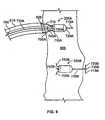
- conventional systemsas shown in FIG 17 , designed to pace the left side of the heart thread a pacing lead 2 through the coronary sinus ostium 7, located in the right atrium 5, and through the coronary venous system 8 to a location 9 in a vein over the site to be paced on the left side.
- veinsWhile a single lead may occlude a vein over the left heart locally, this is overcome by the fact that other veins may compensate for the occlusion and deliver more blood to the heart. Nevertheless, multiple leads positioned in veins would cause significant occlusion, particularly in veins such as the coronary sinus that would require multiple side-by-side leads.
- CHFcongestive heart failure
- resynchronization therapypacing at multiple sites may be beneficial where heart tissue through which electrical energy must propagate is scarred or dysfunctional, which condition halts or alters the propagation of an electrical signal through that heart tissue.
- multiple-site pacingmay be useful to restart the propagation of the electrical signal immediately downstream of the dead or sick tissue area.
- Synchronized pacing at multiple sites on the heartmay inhibit the onset of fibrillation resulting from slow or aberrant conduction, thus reducing the need for implanted or external cardiac defibrillators.
- Arrhythmiasmay result from slow conduction or enlargement of the heart chamber.
- a depolarization wave that has taken a long and/or slow path around a heart chambermay return to its starting point after that tissue has had time to re-polarize. In this way, a never ending "race-track" or "circus” wave may exist in one or more chambers that is not synchronized with normal sinus rhythm.
- Atrial fibrillationa common and life threatening condition, may often be associated with such conduction abnormalities.
- Pacing at a sufficient number of sites in one or more heart chambers, for example in the atriamay force all tissue to depolarize in a synchronous manner to prevent the race-track and circus rhythms that lead to fibrillation.
- wireless electrodesreceive energy for generating a pacing electrical pulse via inductive coupling of a coil in the electrode to a radio frequency (RF) antenna attached to a central pacing controller, which may also be implanted.
- the wireless electrodesare screwed into the outside surface of the heart wall.
- RFradio frequency
- the inventionis directed to a catheter delivery system according to claim 1 and an implantable wireless electrode assembly according to claim 11 and addresses the problem of improving the attachment of the electrode assembly in cardiac tissue.
- This documentdescribes various configurations of systems that employ leadless electrodes to provide pacing therapy or other tissue excitation and that are commercially practicable.
- One of the findings of the inventorsis that a significant issue to be considered in achieving a commercially practicable system is the overall energy efficiency of the implanted system. For example, the energy transfer efficiency of two inductively coupled coils decreases dramatically as the distance between the coils increases. Thus, for example, a transmitter coil implanted in the usual upper pectoral region may only be able to couple negligible energy to a small seed electrode coil located within the heart.
- FIG 1shows a general depiction of such a system 10 and an external programming device 70.
- the system 10includes a number of wireless electrode assemblies 20, herein referred to simply as "seeds.”
- the seeds 20are implanted within chambers of the heart 30.
- each of the seeds 20has an internal coil that is inductively coupled with an external power source coil to charge an electrical charge storage device contained within the seed 20, and also has a triggering mechanism to deliver stored electrical charge to adjacent heart tissue.
- each seedhas no energy storage device such as a battery or capacitor.
- each seedmay be comprised, for example, of a ferrite core having caps at each end with ring electrodes encircling the caps, so as to form a dumbbell-shaped configuration.
- a number of turns of fine insulated wiremay be wrapped around the central portion of the core so as to receive energy from a magnetic field produced by a shaped driving signal and designed to activate the electrodes.
- FIGS. 18A to 18CSuch a configuration is discussed below in greater detail with reference to FIGS. 18A to 18C .
- the system 10also includes a pacing controller 40 and a transmitter 50 that drives an antenna 60 for communication with the seeds 20.
- the pacing controller 40includes circuitry to sense and analyze the heart's electrical activity, and to determine if and when a pacing electrical pulse needs to be delivered and by which of the seeds 20. The sensing capability may be made possible by having sense electrodes included within the physical assembly of the pacing controller 40.
- a conventional single or dual lead pacemakermay sense the local cardiac electrocardiogram (ECG) and transmit this information to antenna 60 for use by controller 40 in determination of the timing of seed firing.
- ECGlocal cardiac electrocardiogram
- the seed 20need not be provided with sensing capability, and also the seeds 20 need not be equipped with the capability of communicating to the pacing controller 40 (for example, to communicate information about sensed electrical events).
- the seedsmay communicate sensed information to each other and/or to the controller 40.
- the transmitter 50which is in communication with, and is controlled by, the pacing controller 40-drives an RF signal onto the antenna 60.
- the transmitter 50provides both 1) a charging signal to charge the electrical charge storage devices contained within the seeds 20 by inductive coupling, and 2) an information signal, such as a pacing trigger signal, that is communicated to a selected one or more of the seeds 20, commanding that seed to deliver its stored charge to the adjacent tissue.
- An important parameter of the seed 20 that is a driver of the system 10 designis the maximum energy required to pace the ventricle.
- This energy requirementcan include a typical value needed to pace ventricular myocardium, but also can include a margin to account for degradation of contact between the electrodes and tissue over time. It is assumed that each seed may require the maximum pacing threshold energy.
- This threshold energyis supplied to the seeds between heartbeats by an external radio frequency generator (which may also be implanted), or other suitable energy source that may be implanted within the body. Typical values are:
- the pacing controller 40 and the transmitter 50may be housed in a single enclosure that is body implantable within a patient.
- the single enclosure devicemay have a single energy source (battery) that may be either rechargeable or non-rechargeable.
- the pacing controller 40 and the transmitter 50may be physically separate components.
- the pacing controller 50may be implantable, for example in the conventional pacemaker configuration, whereas the transmitter 50 (along with the antenna 60) may be adapted to be worn externally, such as in a harness that is worn by the patient.
- the pacing controller 40would have its own energy source (battery), and that energy would not be rechargeable given the relatively small energy requirements of the pacing controller 40 as compared to the energy requirements of the transmitter 50 to be able to electrically charge the seeds 20.
- the pacing controller 40would sense the local cardiac ECG signal through a conventional pacing lead, and transmit the sensed information to the external controller. Again, transmission of information, as opposed to pacing energy, has a relatively low power requirement, so a conventional pacemaker enclosure and battery would suffice.
- the external programmer 70is used to communicate with the pacing controller 40, including after the pacing controller 40 has been implanted.
- the external programmer 70may be used to program such parameters as the timing of stimulation pulses in relation to certain sensed electrical activity of the heart, the energy level of stimulation pulses, the duration of stimulation pulse (that is, pulse width), etc.
- the programmer 70includes an antenna 75 to communicate with the pacing controller 40, using, for example, RF signals.
- the implantable pacing controller 40is accordingly equipped to communicate with the external programmer 70, using, for example, RF signals.
- the antenna 60may be used to provide such communications, or alternatively, the pacing controller 40 may have an additional antenna (not shown in FIG. 1 ) for external communications with the programmer 70, and in an embodiment where the transmitter 50 and antenna 60 are housed separately from the controller 40, for communications with the transmitter 50.
- FIG. 2Ashows an example system 200 of the type shown in FIG 1 .
- the system 200is shown as having been implanted in a patient, and in addition, a programmer 270 is also shown that is external to the patient. As shown, the system 200 is of a type that is entirely implantable.
- the system 200includes several seed electrode assemblies 220, there being four such assemblies shown as having been implanted within the heart 230 in FIG. 2A .
- the system 200also includes an implantable combined pacing controller and transmitter device 240 that has an antenna 260 for communicating, for example, to the seeds 220.
- the controller/transmitter device 240is shaped generally elongate and slightly curved so that it may be anchored between two ribs of the patient, or possibly around two or more ribs.
- the controller/transmitter device 240is 2 to 20 cm long and 1 to 10 centimeters (cm) in diameter, preferably 5 to 10 cm long and 3 to 6 cm in diameter.
- Such a shape of the controller/transmitter device 240which allows the device 240 to be anchored on the ribs, allows an enclosure that is larger and heavier than conventional pacemakers, and allows a larger battery having more stored energy.
- Other sizes and configurationsmay also be employed as is practical.
- the antenna 260 in the FIG 2A exampleis a loop antenna comprised of a long wire whose two ends 270 and 272 extend out of the housing of the controller/transmitter device 240 at one end 280 of the controller/transmitter device 240.
- the opposite ends 270 and 272 of the loop antenna 260are electrically connected across an electronic circuit contained within the controller/transmitter device 240, which circuit delivers pulses of RF current to the antenna, generating a magnetic field in the space around the antenna to charge the seeds, as well as RF control magnetic field signals to command the seeds to discharge.
- the loop antenna 260may be made of a flexible conductive material so that it may be manipulated by a physician during implantation into a configuration that achieves improved inductive coupling between the antenna 260 and the coils within the implanted seeds 220.
- the loop antenna 260may be 2 to 22 cm long, and 1 to 11 cm wide, preferably 5 to 11 cm long, and 3 to 7 cm wide. Placement of the antenna over the ribs allows a relatively large antenna to be constructed that has improved efficiency in coupling RF energy to the pacing seeds.
- the loop antenna 260has been configured to extend generally around the periphery of the housing of the controller/transmitter device 240.
- the loop antenna 260extends from its first end 270 (located at the first end 280 of the controller/transmitter device 240) outwardly and then generally parallel to the elongately shaped controller/transmitter device 240 to the second end 282 of the controller/transmitter device 240.
- the loop antenna 260extends outwardly and again generally parallel to the controller/transmitter device 240, albeit on an opposite side of the transmitter/controller device 240, and back to the first end 280 of the controller/transmitter device 240.
- the loop antenna 260may, like the controller/transmitter device 240, be anchored to the ribs of the patient.
- the distance between the center of the loop antenna 260 and the seed electrode assemblies 220will typically be, on average, about three inches (3"). As will be shown later, such a distance puts significant power demands on the controller/transmitter device 240, and so an internal battery included within the controller/transmitter device 240 may need to be rechargeable. In some embodiments, however, the controller/transmitter device 240 may be non-rechargeable.
- the loop antenna 260may have a shape that is more complex than that shown in FIG. 2 , with a larger antenna area, or multiple antenna lobes to capture more tissue volume.
- the antennamay consist of two or more wire loops, for example, one on the front of the patient's rib cage, and a second on the back, to gain magnetic field access to a larger tissue region.
- FIG 2Bthere is shown an embodiment as shown in FIG 2A , but which also includes a conventional pacemaker, or pulse generator, 290 and associated wired leads 295 which extend from the pulse generator 290 and into chambers of the heart 600.
- the pulse generator 290may be used to sense the internal ECG, and may also communicate with the controller/transmitter 240 as discussed previously.
- a battery 302which may be recharged by receiving RF energy from a source outside the body via antenna 260; ECG sensing electrodes 304 and associated sensing circuitry 306; circuitry 308 for transmitting firing commands to the implanted seeds, transmitting status information to the external programmer, receiving control instructions from the external programmer and receiving power to recharge the battery; and a controller or computer 310 that is programmed to control the overall functioning of the pacing control implant.
- antenna 260may receive signals from the individual seeds 220 containing information regarding the local ECG at the site of each seed, and/or antenna 260 may receive signals from a more conventional implanted pacemaker regarding the ECG signal at the sites of one or more conventional leads implanted on the right side of the heart.
- FIG 4is a schematic diagram of an exemplary wireless electrode assembly, or seed, 420 that may serve as the seeds 20 or 220 as shown in either FIG. 1 or FIGS. 2A-B .
- the seed 420includes, firstly, a receiver coil 410 that is capable of being inductively coupled to a magnetic field source generating a time-varying magnetic field at the location of coil 410, such as would be generated by the transmitter 50 and the antenna 60 shown in FIG 1 .
- the RF current in the external antennamay be a pulsed alternating current (AC) or a pulsed DC current, and thus the current induced through the receiver coil 410 would likewise be an AC or pulsed DC current.
- ACpulsed alternating current
- DCpulsed DC current
- the current induced in coil 410is proportional to the time rate of change of the magnetic field generated at the site of coil 410 by the external RF current source.
- a four-diode bridge rectifier 415is connected across the receiver coil 410 to rectify the AC or pulsed DC current that is induced in the receiver coil 410.
- a three-position switch device 418is connected so that when the switch device 418 is in a first position, the rectifier 415 produces a rectified output that is imposed across a capacitor 405. As such, when the switch device 418 is in the position 1 (as is the case in FIG. 4 ), the capacitor 405 stores the induced electrical energy.
- the switch device 418in this example, is a voltage-controlled device and is connected to sense a voltage across the capacitor 405 to determine when the capacitor 405 has been sufficiently charged to a specified pacing threshold voltage level. When the capacitor 405 is sensed to have reached the specified pacing threshold level, the voltage-controlled switch device 418 moves to a position 2, which disconnects the capacitor 405 from the coil 510. With the switch device 418 in the position 2, the capacitor 405 is electrically isolated and remains charged, and thus is ready to be discharged.
- the voltage controlled switch device 418may consist of a solid state switch, such as a field effect transistor, with its gate connected to the output of a voltage comparator that compares the voltage on capacitor 405 to a reference voltage.
- the reference voltagemay be set at the factory, or adjusted remotely after implant via signals sent from the physician programmer unit, received by coil 410 and processed by circuitry not shown in FIG 4 .
- Any electronic circuitry contained within the seed, including the voltage controlled switch,is constructed with components that consume very little power, for example CMOS. Power for such circuitry is either taken from a micro-battery contained within the seed, or supplied by draining a small amount of charge from capacitor 405.
- a narrow band pass filter device 425is also connected across the receiver coil 410, as well as being connected to the three-position switch device 418.
- the band pass filter device 425passes only a single frequency of communication signal that is induced in the coil 410.
- the single frequency of the communication signal that is passed by the filter device 425is unique for the particular seed 20 as compared to other implanted seeds.
- the filter device 425passes the voltage to the switch device 418, which in turn moves to a position 3.
- the capacitor 405With the switch device in the position 3, the capacitor 405 is connected in series through two bipolar electrodes 430 and 435, to the tissue to be stimulated. As such, at least some of the charge that is stored on the capacitor 405 is discharged through the tissue. When this happens, the tissue becomes electrically depolarized.
- the bipolar electrodes 430 and 435 across which stimulation pulses are providedare physically located at opposite ends of the seed 420. After a predetermined, or programmed, period of time, the switch returns to position 1 so the capacitor 405 may be charged back up to the selected threshold level.
- FIG. 4shows only the seed electrical components for energy storage and switching. Not shown are electronics to condition the pacing pulse delivered to the tissues, which circuitry would be known to persons skilled in the art.
- Some aspects of the pulsemay be remotely programmable via encoded signals received through the filter device 425 of the seed 420.
- filter 425may be a simple band pass filter with a frequency unique to a particular seed, and the incoming signal may be modulated with programming information.
- filter 425may consist of any type of demodulator or decoder that receives analog or digital information induced by the external source in coil 410.
- the received informationmay contain a code unique to each seed to command discharge of capacitor 405, along with more elaborate instructions controlling discharge parameters such as threshold voltage for firing, duration and shape of the discharge pulse, etc.
- all of the implanted seedsmay be charged simultaneously by a single burst of an RF charging field from a transmitter antenna 60. Because back reaction of the tiny seeds on the antenna 60 is small, transmitter 50 ( FIG 1 ) losses are primarily due to Ohmic heating of the transmit antenna 60 during the transmit burst, Ohmic heating of the receive coil 410, and Ohmic heating of conductive body tissues by eddy currents induced in these tissues by the applied RF magnetic field. By way of comparison, if eight seeds are implanted and each is addressed independently for charging, the transmitter 50 would be turned ON eight times as long, requiring almost eight times more transmit energy, the additional energy being primarily lost in heating of the transmit antenna 60 and conductive body tissues.
- FIG 5is a flowchart of a pacing cycle that shows such a mode of operation of charging all implanted seeds 20 simultaneously, and triggering the discharge of each seed 20 independently.
- the methodstarts at step 510 with the start of a charging pulse that charges all of the seeds simultaneously.
- a pacing threshold voltageis attained or exceeded, at step 520, the seeds switch to a standby mode (for example, switch 418 in seed 420 moves to position 2).
- a controller/transmitter devicesuch as device 240 shown in FIG 2 , transmits a trigger pulse at a particular frequency (f1) that is passed through a band pass filter (such as filter device 425) in the seed to be fired (for example, seed 1).
- step 540that seed, namely seed 1, receives the trigger pulse through the band pass filter, which in turn trips the switch to pace the tissue.
- This processmay be repeated for each of the N number of seeds that have been implanted, as indicated at step 550, which returns to step 530 where there are additional seeds that have been charged and are to be fired.
- step 560there is a delay until the next diastole, after which time the process begins anew at step 510.
- the exact time of firing of the first seedmay be programmed by the physician in relation to the ECG signal features measured by the sensing electrodes 304 in FIG 3 , or in relation to ECG information transmitted to the controller 240 by the pacing seeds themselves, or in relation to pacing information transmitted to the controller 240 by a conventional implanted pacemaker, or in relation to pacing information received from a conventional implanted pacemaker through an implanted hard wire connection to controller 240.
- Subsequent timing of the firing of each additional seedmay be programmed by the physician at the time of implant.
- seedsmay be programmed not to discharge. For example, an array of seeds may be implanted, but only a subset may be programmed to receive firing commands from the controller 240.
- the controller/transmitter device 240 and associated antenna 260would first be implanted subcutaneously in a designed location (for example, between the ribs in the case of the FIG. 2A embodiment). The physician then may program the controller/transmitter 240 by delivering telemetric signals through the skin using the programmer 270 in a conventional manner, although this programming may also be done, at least in part, before implantation.
- One of the adjustable parametersis the timing of firing of each seed 220, determined by a time at which a short burst of current at the frequency for the particular seed 220 is delivered to the antenna 260.
- the controller/transmitter device 240may have a pair of sensing electrodes on its surface to detect the subcutaneous electrocardiogram (ECG), or it may contain multiple electrodes to provide a more detailed map of electrical activity from the heart.
- ECGsubcutaneous electrocardiogram
- This local ECG signal sensed by the controller/transmitter device 240may be used to trigger the onset of seed pacing when the patient has a functioning sinus node.
- the signals sensed by the controller/transmitter device 240are used to monitor ECG signals from the paced heart. In some cases, these ECG signals, or other physiologic sensor input signals, may be used to adjust or adapt the timing of firing of the pacing seeds 220.
- the controller 240may receive local ECG or pacing information through an RF link from a conventional pacemaker 290 implanted in the pectoral region of the patient, as shown in FIG. 2B .
- Thismay be desirable in patients who already have a conventional pacemaker, or when local ECG data from the conventional atrial or right ventricular apex pacing sites are desired to coordinate the timing of firing of the implanted seeds 220.
- the seeds 220could themselves transmit information to controller 240 concerning the local bipolar ECG measured at their sites.
- the seeds 220could sense the local ECG and discharge based upon this local data, with no firing instructions from the controller 240 required, or the seeds 220 could transmit information from seed 220 to seed concerning local ECG and onset of their discharge. All of the above embodiments, a combination, or a subset, may be implemented in this invention.
- the seeds 220would be delivered to their respective sites in the cardiac veins, within the heart wall, or on the epicardial surface of the heart via a catheter, as will be described in more detail later.
- a distal portion, or tip of the cathetermay contain a single electrode or a pair of electrodes, each being connected to a signal recorder via leads extending to a proximal end of the catheter.
- the physicianwould select the implantation site based upon features of the ECG signal sensed using the catheter.
- the seedthen may be injected through a needle extended from the catheter tip, or it may be pushed into the tissue and then released from the catheter. Many mechanisms may be used for seed release, including the release or addition of fluid pressure to the catheter tip.
- the seed 220may be charged and then fired to observe the altered electrogram proximate the seed at the location of the catheter tip.
- the physiciancan adjust the timing of seed firing by programming the controller/transmitter device 240.
- the catheteror a seed delivery mechanism residing within the catheter
- the cathetermay be removed, and a new delivery mechanism containing the next pacing seed may be inserted and navigated to the next pacing site. Because seeds can be fired in any order, or not fired at all, a physician may deliver the seeds in any order. When the heart is deemed to be beating in synchrony, no further seeds need be implanted.
- an array of seedsmay be delivered to the veins and/or heart wall, and the physician can program a subset of seeds to fire in a sequence that optimizes the pumping efficiency of the heart. Ejection fraction and cardiac output may be measured to determine pumping efficiency. On any given heartbeat, some or all of the seeds would fire.
- the controller 240may be programmed to sequentially fire seeds, or some seeds may fire simultaneously.
- FIGS. 6-10show an example of a mechanical design for a seed electrode assembly and an example seed delivery device and method.
- a system of the type shown in FIG. 2is shown where three seed electrode assemblies 220 have been implanted within tissue of the heart 600, and in particular, within a myocardial wall 605 of the heart 600.
- the controller/transmitter device 240is shown implanted beneath the skin 610 of the patient.
- the antenna 260extends from within the controller/transmitter device 240 at one end of the device 240, and then extends around the periphery of the device 240, as described previously.
- the external programming device 270is also shown, which is used to communicate with the implanted controller/ transmitter 240.
- Distal portions of two seed delivery catheters 615are shown in FIG 6 , each extending within a chamber of the heart 600 and to a site near where one of the seeds 220 is located.
- the delivery catheter 615enables placement of a seed 220 and the ability to sense the electrical activity at the distal tip of delivery catheter 615 through catheter tip electrode 625, so that a physician can determine if the location is a good candidate location for implantation of seed 220. If the location is a good candidate, the seed 220 may be partially inserted into the tissue as shown in FIG 9 .
- the seed 220may be charged and then discharged into the tissue, while the physician observes electrograms, including the local electrogram arising from electrode 625, and perhaps an electrogram from the distal seed electrode taken through the pull wire 735A.
- the seed 220may be removed from that site and positioned elsewhere. If it is an appropriate location, then the seed 220 has an anchoring mechanism that can be activated to implant the seed 220 permanently within the tissue so that it retains its location.
- Each of the catheters 615is shown in FIG. 6 extending into the heart 600 through a heart entry vessel 620 such as the inferior vena cava (for right chamber entry) or aortic valve (for left chamber entry).
- a distal portion 625 of the delivery catheter 615includes a sensing electrode for sensing the electrical activity at a tissue site where the seed 220 may be implanted.
- FIG 7shows one of many possible embodiments of a wireless electrode assembly, or seed, 220.
- the seed 220is shown in FIG 7 within a distal portion of the seed delivery catheter 615.
- the seed 220has a main body 702 that, in this example, is bullet shaped and has two bipolar electrodes 705 and 710.
- One of the electrodes, namely electrode 705,is located at a distal tip of the bullet-shaped seed body 702, and the other electrode 710 is located at a proximal end of the seed body 702.
- the bullet shape of the seed body 702enables it to be extended into tissue such as the myocardial wall 605, as will be illustrated in later figures.
- the "nose," or distal tip, of the seed body 702may be more cone-shaped than the embodiment shown in FIG. 7 . While the distal and proximal electrodes 705 and 710 are shown on the seed itself, other locations are possible, including placing the distal and proximal electrodes 705 and 710 at the ends of the attachment tines to achieve the maximum separation between electrodes.
- the seed delivery catheter 615consists of an elongate tube with a main lumen 712 extending though its entire length.
- the catheter 615has an opening 713 at its distal end so that the seed 220 may be released from the delivery catheter 615.
- the catheter 615also has the previously discussed electrode 625, which as shown extends around the periphery of the distal opening 713.
- An electrically conductive lead 716is attached to the electrode 625 and extends proximally through the entire length of catheter lumen 712, or through the wall of the catheter, and outside the body (not shown in FIG 7 ).
- the lead 716is made of an electrically conductive material, and thus provides the local electrocardiogram (ECG) appearing at the distal electrode 625.
- ECGelectrocardiogram
- the main lumen 712 of the seed delivery catheter 615may have an internal diameter of about two-and-a-half millimeters, and the seed delivery catheter 615 may have an outside diameter that is slightly larger than that.
- the seed body 702may have a width of about two millimeters, and the length of the seed body 702 may be about five to ten millimeters, for example. This enables the seed 220 to be implanted entirely within a myocardial wall 605, which may, for example, be about 20 millimeters thick in the left ventricle.
- the seed 220has a pair of forward-end tines 715 and 720 that each extend from a common junction point 725. Each of the tines 715 and 720 may be about three to eight millimeters in length, for example.
- the seed body 702also has a central bore 730 extending longitudinally through a center of the seed body 702. In FIG. 7 , which shows the seed 220 not yet implanted, one of the forward-end tines, namely tine 720, extends proximally into the bore 730, while the other forward-end tine 715 extends distally to enable it to pierce through tissue.
- junction point 725 for the tines 715 and 720may be pushed forward of the seed 220 body, and when the constrained tine 720 clears the central bore 730, the tines 720 and 715 are biased to snap into a lateral configuration that will be shown in a later figure.
- the junction point 725is physically larger than the diameter of the central bore 730, and thus enables the seed 220 to be pulled in a proximal direction by pulling on extraction wire 735.
- the seed extraction wire 735is attached to the junction point 725, and extends proximally through the entire length of the seed central bore 730, and from there continues proximally through the delivery catheter 615 and outside the body (not shown in FIG 7 ).
- the wire 735may be made of an electrically conductive material so as to sense an electrical signal appearing at a distal end of the wire 735, thus serving as an extraction pull wire and as a temporary ECG lead for distal electrode 705. This is a means of sensing a bipolar electrocardiogram at a proposed implantation site before permanently implanting the seed 220, using electrode 705 (with wire lead 735) as a first electrode, and using the catheter electrode 625 and lead 716 as a second electrode.
- the extraction wire 735extends outside the patient's body, a physician may pull the wire 735, and given that the junction point 725 is too large to be pulled into the seed body central bore 730, pulling the wire 735 pulls the seed 220 proximally within the delivery catheter 615.
- the extraction wire 735is also constructed of a material and of a diameter such that the wire 735 is rigid enough to be pushed forward to extend the junction point 725 forward of the seed 220 body and hence free the forward-end tine 720 from the constraining central bore 730.
- the wire 735has stopper device 740 that is attached to the wire 735 at a point that is proximal of the seed 220 body.
- the stopper device 740like the junction point 725, is larger than the seed body central bore 730, and thus constrains how far the lead junction point 725 can be extended forward of the seed body 702.
- the stopper device 740is positioned on the wire 735 at a location that is far enough away from the rear-end of the seed body 702 such that wire 735 may be pushed distally far enough to free the constrained tine 720 from the seed body central bore 730.
- the extraction wire 735has a detachment mechanism 745 located on the wire 735 at a point that is immediately distal of the stopper device 740.
- the detachment mechanism 745may be activated by a physician to detach the portion of wire 735 that is proximal of the detachment mechanism 745.
- Various detachment mechanismsmay be used for the detachment mechanism 745.
- the detachment mechanism 745may be a high-resistance portion of a conductive line that extends proximally to a point external of the patient, and that can be heated and detached by injecting current of a specified amount into the conductive line.
- the wire 735may serve three purposes: extraction of a seed 220 from a location that does not provide optimal cardiac resynchronization; conduction of the tip electrode 705 ECG signal to a recorder outside the body; conduction of a burst of current to detach itself at a point 745 of relatively high electrical resistance.
- the detachment mechanism 745is a mechanical configuration where the proximal detachable portion of the lead 735 may be unscrewed from the remainder of the lead 735, or where the lead 735 is pushed and turned in a certain way to effect detachment of the proximal portion from the remainder of the lead 735.
- a mechanical skiving or shearing meansmay alternatively be applied at point 745.
- the seed 220also has a pair of tines 750 and 755 that extend from the rear end of the seed body 702.
- the tines 750 and 755assist in securing the seed 220 at a desired location within the tissue, such as within a desired location of the myocardial wall 605, to prevent the seed from migrating under the repeated stress of heart muscle contraction.
- the tines 750 and 755, in this example,are attached to the rear-end electrode 710 near a periphery of the electrode 710, and extend from their attachment points in a direction that is about 45 degrees from a longitudinal axis of the seed body 702.
- a tube 760 that is movable longitudinally within the catheter 615is used to push the seed 220 distally within the catheter 615 and out of the catheter distal opening 713.
- the tubehas a lumen 765 extending longitudinally through its entire length so that the wire 735 extends through the tube lumen 765.
- the cross-sectional diameter of the pusher tube 760may be, for example, about half that of the catheter lumen 712. As such, where the catheter lumen 712 diameter is about 2.5 mm, the tube cross-sectional diameter may be about 1.25 mm.
- the seed delivery catheter 615with a seed 220 contained within, is shown with its circular distal electrode 625 pressed against the myocardial wall 605.
- the electrical activity occurring at that site of the myocardial wall 605is monitored at a proximal end of the lead 716 to determine if the site is an appropriate candidate site in which to implant the seed 220.
- the first seed 220Ais shown during the process of implanting the seed 220A within the myocardial wall 605, with the assistance of the seed delivery catheter 615.
- the second seed 220Bis shown as having already been permanently implanted within the myocardial wall 605.
- the first seed 220Ais shown as having been pushed nearly entirely within the myocardial wall 605. This was accomplished by the physician pushing the push tube 760 within the seed delivery catheter 615 so as to push the seed 220A out of the catheter's distal opening 713.
- the forwardly extending distal tine 715served to pierce the myocardial wall 615 and permit implantation within the wall 615.
- the seed's rear-end tines 750A and 755Aare still partially within the seed delivery catheter 615 and thus are still being constrained from extending outwardly from the seed body's longitudinal axis. As such, it is still possible for the physician to pull back the seed 220A from this position by pulling on the seed extraction wire 735A. If the seed 220A were to have been pushed a little further so that the proximal tines 750A and 755A become extended, then it may not be possible to pull back the seed 220A. As discussed previously, seed 220A may be charged and commanded to discharge while wire 735 serves as a lead to monitor the electrical activity at the forward end of the seed 220A. The physician may determine that the present positioning is not appropriate, and wire 735 may then be pulled to extract the seed, which may then be moved to an alternate location.
- the wire 735has not yet been pushed forward to deploy the distal tines 715A and 720A (750A not shown in FIG. 9 ).
- Deploying the distal tines 715A and 720Ais done as follows. First, the pushing tube 760 is used to push the seed 220A so that, firstly, the proximal tines 750A and 755A are freed from the delivery catheter 615 and thus extend outwardly, and secondly, the seed's distal tine junction point 725A extends distally of the seed, and preferably entirely through the myocardial wall 605.
- junction point 725A and one of the forward-end tines 715are both positioned outside the myocardial wall 605 in Figure 9 .
- the wire 735Ais pushed distally until the lead stopper device 740 becomes flush with the proximal seed electrode 710A.
- the constrained tine 720Abecomes removed from the seed body central bore, thus allowing the two distal tines 715A and 720A to pop into the lateral position.
- Seed 220Bis shown in the deployed position, the proximal tines 750B and 755B are shown extended, and the two distal tines 715B and 720B are outside the myocardial wall 605 and extend laterally from the junction point 725B.
- a flowchartis shown that describes a method of delivering a seed 220 using the catheter 615 or another similar delivery device.
- the methodbegins at step 1010 with the percutaneous transluminal delivery of the catheter 615 to the heart chamber. This may be accomplished in the following manner. First, an introducer is used to provide entry into, for example, the femoral vein or artery (depending on where the seed 220 is to be delivered). The catheter 615 is then inserted so that its distal end is snaked through the inferior vena cava and into the right atrium, for example. Thus, a seed 220 may be delivered in the right atrium.
- the distal end of the catheter 615may also be moved from the right atrium, through the tricuspid valve, and into the right ventricle, for delivery of a seed 220 there.
- the distal end of the cathetermay also be pushed through the fossa ovalis, accessed on the right atrial septum, for placement of seeds 220 in the left heart chambers.
- the distal end of the catheter 615may be snaked through the femoral artery and descending aorta, through the aortic valve and into the left ventricle, and from the left ventricle may be moved through the mitral valve into the left atrium. Navigating the catheter 615 may require that the catheter 615 have some type of navigational capability such as push and pull wires commonly used with electrophysiology catheters.
- a sample ECG signalmay be taken at sites on the heart inner wall. This may be done with the catheter 615 positioned as shown in FIG. 8 , for example.
- the physicianselects a site at which to deliver the seed 220.
- the physiciandelivers the seed 220 into the myocardial wall tissue, such as shown with seed 220A in FIG. 9 .
- the seed 220is still tethered by the lead 735A so that the seed may be pulled back into the delivery catheter 615 if necessary.
- a test paceis performed to test the response at this site. This may be done using the programmer 270 shown in FIG. 6 to instruct the controller/transmitter device 240 to send a charging signal and then a trigger signal to the particular seed 220.
- the seed 220may be removed and the process may be performed again starting at step 1020. If, on the other hand, the pacing response is found to be acceptable, then, at step 1060, the anchoring means for the seed 220 may be activated, for example, by moving the seed 220 entirely out of the catheter 615 and freeing the proximal tines 750 and 755 from the constraints of the catheter 615 and pushing the lead 735 to release the distal tines 715 and 720. Also at step 1060, the tether to the seed 220 may be released, for example, using the detachment mechanism 745. Having completed the implantation of the seed, it is now possible at step 1070 to begin placement of the next seed 220.
- each of the seeds 220may have a filter 425 (see FIG. 4 ) that allows passage of a signal of a particular frequency.
- each of the seeds 220may have a band pass filter 425 of a different center frequency.
- seeds 220may be manufactured as having one of sixteen different band pass frequencies.
- a code for the particular pass frequencymay be labeled directly on the seed 220 itself, or alternatively, may be labeled on the packaging for the seed 220.
- the particular band pass frequency for each seed 220is communicated to the pacing controller 240.
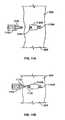
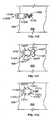
- FIG. 11Ashows a seed 1120A that is secured into the myocardium 605 with a distal spring 1105A, or "cork screw.”
- a delivery rod 1110 provided by a delivery catheter 1112is detached from the seed 1120A by turning the rod 1110 to engage the spring into tissue and also unscrew the threaded distal rod section 1115 from the seed 1120A.
- a distal spring 1105Bis screwed into the myocardium 605 using a clockwise rotation of the seed 1120B, which also unscrews the delivery rod from the seed.
- proximal spring 1125is exposed to the myocardium 605.
- Clockwise spring 1105B and counter-clockwise spring 1125together prevent rotation and translation of the seed through the myocardium.
- a mechanism for release of the springsis not shown in the figure.
- a small push rod passing through the delivery rod and seedcould be used to push the distal spring from the seed and into a locked position.
- a thin sheathcould cover proximal spring 1125. The thin sheath would be retracted along with the delivery rod.
- Alternate means for detachment of the delivery rodinclude Ohmic heating of a high resistance portion of the rod, and mechanical shearing.
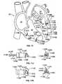
- tines 1130are pushed, using a push rod 1135 provided through the main lumen of the delivery catheter 1112, from the central portion of the seed 1120C, out through channels 1140 and into the myocardium 605, so that the tines 1130 extend laterally from the seed 1120C body (as shown in FIG 11D ), and so that the seed 1120C becomes secured within the tissue.
- the push rod 1135is removable, at an attachment point, from a proximal end junction point 1145 of the tines 1130.
- Various mechanisms for removing, or detaching the push rod 1135 from the tine proximal end junction point 1145may be employed, as discussed previously in connection with the FIG 7 embodiment.
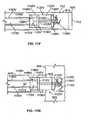
- some embodiments that are envisioned for seed delivery and detachmentinclude a seed 1120E having a helical tine 1105E and one or more adjustable tines 1110E that secure the seed 1120E to the myocardium 605.
- detachment mechanisms 1145E and 1165Emay be used to release the seed 1120E from an elongate shaft 1160E after the seed 1120E is secured to the myocardium 605.
- the seed 1120Eis shown within a distal portion of the seed delivery catheter 615.
- the seed 1120Ehas a main body 1122E that, in this example, is cylindrically shaped with a tip portion 1123E at a distal end.
- the seed 1120Emay include two bipolar electrodes 1135E and 1136E that are capable of discharging an electrical pulse. Electrode 1135E is located at the distal end of seed body 1122E, and the other electrode 1136E is located at a proximal end of the seed body 1122E.
- the tip portion 1123E of the seed body 1122Ehas a modified cone shape that facilitates delivery of the distal end of the seed 1120E into tissue such as the myocardial wall 605, as will be illustrated in later figures.
- the tip portion 1123Emay serve as a strain relief mechanism for the adjustable tines 1110E that extend from the tip portion 1123E.
- the tip portion 1123Emay also deliver a steroid elution to minimize the formation of fibrous tissue at the seed/myocardium interface. While the distal and proximal electrodes 1135E and 1136E are shown on the seed body itself, other locations are possible.
- the distal electrode 1135Emay be disposed at the end of the helical tine 1105E to achieve the maximum separation between electrodes, or may be an entire tine.
- the surface of tip portion 1123E on the seed body 1122Emay function as the distal electrode 1135E, which may provide a more efficient use of space when the seed body 1122E is substantially smaller in size.
- using the surface of tip portion 1123E to function as the distal electrode 1135Emay be desirable in circumstances where only the tip portion 1123E contacts the endocardium or myocardium tissue (described in more detail below).
- the seed delivery catheter 615includes an elongate tube with a main lumen 712 extending though its entire length.
- the catheter 615has an opening 713 at its distal end so that the seed 1120E may be released from the distal end of the delivery catheter 615.
- all or a portion of the seed 1120Emay extend from the delivery catheter 615 before the seed 1120E is secured to the heart tissue.
- the main lumen 712may still be sized to slidably engage the elongate shaft.
- the catheter 615may also have an electrically conductive lead 716 and an electrode 625 that extends around the periphery of the distal opening 713 and is capable of providing local ECG information as previously described.
- the distal end of the catheter 615may include a screw mechanism to temporarily secure the catheter 615 to the heart tissue (described in more detain below in connection with FIG 13 ).
- the seed 1120Ehas a plurality of adjustable tines 1110E that each extend from a common junction member 1112E. As shown in FIG. 11E , each of the adjustable tines 1110E generally extend from the junction member 1112E through a central bore 1130E of the seed body 1122E. FIG 11E shows the seed 1120E not yet implanted, and only the helical tine 1105E extends from the seed body 1122E while the adjustable tines 1110E are disposed in the central bore 1130E. As will be described in more detail later, the junction member 1112E may be pushed in a distal direction by an actuation rod 1170E, thereby forcing the adjustable tines 1110E from the distal end of the central bore 1130E.
- the tines 1110EWhen the constrained tines 1110E extend from the central bore 1130E, the tines 1110E are biased to extend in a curled or hook configuration.
- the junction member 1112Emay be physically larger than the diameter of the central bore 1130E, providing a stopping point for actuation of the adjustable tines 1110E.
- the elongate shaft 1160Eincludes a detachment mechanism 1165E at a distal end that is capable of engaging/disengaging the detachment mechanism 1145E of the seed 1120E.
- the detachment mechanism 1165Eincludes a threaded member that engages a complementary threaded member on the seed's detachment mechanism 1145E.
- the threaded engagement between the detachment mechanisms 1165E and 1145Emay be arranged so that the threads would not release when the seed 1120E is being advanced into the tissue with the rotation of the helical tine 1105E.
- the elongate shaft 1160Econtinues proximally through the delivery catheter 615 and outside the patient's body (not shown in FIG 11E ).
- a physicianmay direct the seed body 1122E (via the elongate shaft 1160E coupled thereto) through the lumen 712 of the delivery catheter 615.
- the delivery catheter 615may be navigated through an access catheter or other steerable sheath to the implantation site.
- the access catheteris capable of maintaining a stable valve crossing, which can reduce trauma to the valve and facilitate the implantation of multiple seeds into the wall of the heart chamber.
- the elongate shaft 1160Emay be constructed of a material and of a size and design such that the elongate shaft 1160E is sufficiently rigid to be rotated within the main lumen for purposes of engaging the helical tine 1105E with the myocardium tissue. Also, the elongate shaft 1160E may be sufficiently flexible so as to not impede navigation of the elongate shaft 1160E and the catheter 615 to the implantation site.
- the actuation rod 1170Emay be disposed in a lumen 1162E of the elongate shaft 1160E.
- the actuation rod 1170Eincludes an engagement surface 1172E that is adapted to contact the junction member 1112E. From the engagement surface 1172E, the actuation rod 1170E may continue proximally through the elongate shaft 1160E and outside the patient's body. In such embodiments, a physician may apply a force at the proximal end of the actuation rod 1170E so as to slide the rod 1170E within the elongate shaft 1160E. Such motion of the elongate rod 1170E may apply a distal force upon the junction member 1112E.
- the actuation rod 1170Emay be constructed of a material and be of a size such that the actuation rod is sufficiently rigid to push against the junction member 1112E and force adjustable tines 1110E to extend from the distal end of the central bore 1130E. Also, the elongate rod 1170E may be sufficiently flexible so as to be guided through the lumen 1162E of the elongate shaft 1160E.
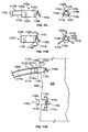
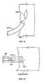
- FIGS. 11F-11Hat least a portion of the seed 1120E shown in FIG 11E may be implanted into myocardium 605.
- the delivery catheter 615may be guided into a heart chamber (e.g., left atrium 32, left ventricle 34, right atrium 36, or right ventricle 38) to enable placement of at least a portion of the seed 1120E from the heart chamber into the myocardium 605.
- the seedmay pass necessarily from the distal opening 713 of the catheter 615, through an inner lining of the heart wall (e.g., the endocardium 606), and into the myocardium 605.
- FIGS. 11F-11Hshow a seed 1120E that is being implanted into the myocardium 605 and also show a neighboring seed 1120E (below the first seed 1120E) that was previously secured to the myocardium 605.
- the seed 1120E in the lumen 712 of the delivery catheter 615may be directed toward the distal end by a force 1167E from the elongate shaft 1160.
- the distal end of the delivery catheter 615may abut (or be positioned proximate to) the inner surface of the heart chamber so that the seed 1120E is guided to a selected site of the heart wall.
- adjustable tines 1110E of the seed 1120E in the delivery catheter 615are not in an actuated position where they extend from the distal end of the central bore 1130E (the adjustable tines 1110E of the neighboring seed 1120E that was previously implanted are shown in an actuated position).
- the helical tine 1105Eis configured to penetrate through the endocardium 606 and into the myocardium 605, as described in more detail below.
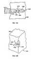
- the seed 1120E in the lumen 712 of the delivery catheter 615may be rotated by a torsional force 1168E from the elongate shaft 1160.
- the helical tine 1105Emay be "screwed" into the heart wall. In such circumstances, the helical tine 1105E penetrates through the endocardium 606 and into the myocardium 605.
- the detachment mechanism 1145Eincludes a threaded member
- the torsion force 1168E from the elongate shaft 1160Emay serve to maintain or tighten the threaded engagement.
- the seed's adjustable tines 1110Eare not extended from the central bore 1130E (as shown by the neighboring seed). As such, it is still possible for the physician to pull back the seed 1110E from this position by rotating the elongate shaft 1160E in a direction opposite of force 1168E, which would cause the helical tine 1105E to "unscrew" from the myocardium tissue.
- the seed's distal electrode 1135Eis in contact with the myocardium 605.
- seed 1120Emay be commanded to discharge a pacing electrical pulse while electrode 625 on the delivery catheter 615 monitors the electrical activity at the selected site.
- the seed 1120Emay be retracted into the delivery catheter lumen 712, which may then be moved to an alternate location. At the alternate location, the helical tine 1105E would again penetrate through the endocardium and into the myocardium 605, in which case further monitoring of electrical activity may occur.
- the adjustable tines 1110Emay be forced to an actuated position.
- the actuation rod 1170E disposed in the elongated shaft 1160Eis capable of applying a force on the junction member 1112E.
- the adjustable tines 1110Eextend from the distal end of the central bore 1130E.
- the adjustable tines 1110Eare biased to have a curled or hook shape when unconstrained by the central bore 1130E.
- the adjustable tines 1110Emay comprise a shape memory alloy material, such as nitinol or the like, that is capable of returning to its biased shape after being elastically deformed within the central bore 1130E.
- the adjustable tines 1110Eembed in the myocardium 605 to provide supplemental anchoring support and to substantially hinder additional rotation of the seed body 1122E.
- the elongate shaft 1160Emay be rotated backward relative to the seed body 1122E, which causes the threaded members of detachment mechanisms 1165E and 1145E to disengage one another.
- the elongate shaft 1160Emay be rotated relative to the seed body 1122E without extracting the seed 1120E from the myocardium 605 because the adjustable tines 1110E prevent the helical tine 1105E from being "unscrewed.” After the seed 1120E is detached from the elongate shaft 1160E, the delivery catheter 615 and the elongate shaft 1160E may be withdrawn from the implantation site.
- the adjustable tinesalso reduce the likelihood of the seed body 1122E being pulled or torn from the heart wall.
- the seed 1120Emay be exposed to various forces from the beating heart and the turbulence of the blood in the heart chambers.
- the seed 1120Emay be attached to the heart wall so that a threshold amount of pull force is required to remove the seed 1120E from the heart wall.
- Certain embodiments of seed 1120Emay be secured to the heart wall such that a pull force of greater than 0.3 lbs. is required to remove the seed body 1122E from the heart wall.
- the a seed 1120Emay be secured to the heart wall such that a pull force of greater than 0.5 lbs., and preferably greater than 1.0 lbs., is required to remove the seed body 1122E from the heart wall.
- Several seeds 1120Ewere secured to the myocardium of a porcine (pig) heart using the helical tine 1105E and three adjustable tines 1110E.
- the porcine heartwas delivered to a lab where a portion of it was removed by scalpel to reveal an internal heart chamber.
- Several seeds 1120Ewere secured to the porcine heart wall from the internal heart chamber-first by rotating the helical tine 1105E into the myocardium and then by actuating the adjustable tines 1110E to a curled shape substantially within the myocardium tissue.
- Each of the seeds 1120Ewas secured to the heart wall such that a pull force of greater than 0.3 lbs. was required to remove the seed body 1122E from the heart wall, and in some instances, a pull force of greater than 1.0 lbs. was required.
- helical tine 1105E and the adjustable tines 1110Emay secure the seed 1120E to the myocardium 605 such that at least a portion of the seed body 1122E (e.g., the tip portion 1123E) penetrates into the myocardium 605.
- the seed body 1122Emay be fully inserted into the myocardium tissue.
- a distal portion of the seed body 1122Eextends into the myocardium 605 while a proximal portion of the seed body 1122E is exposed to the heart chamber (e.g., left atrium 32, left ventricle 34, right atrium 36, or right ventricle 38).
- the seed body 1122Emay be secured to the myocardium 605 so that the distal electrode 1135E is in contact with the myocardium while the proximal electrode 1136E is exposed to the heart chamber (and the blood therein). In certain cases, such positioning of the seed body 1122E may be dictated by a limited thickness in the myocardium wall.
- the seed body 1122Emay not fully penetrate into the myocardium 605.
- a portion of the seed 1120Ee.g., the helical tine 1105E and the adjustable tines 1110E
- the tip portion 1123Emay contact or penetrate into the endocardium (and perhaps partially into the myocardium), but the other portions of the seed body 1122E may not penetrate into the heart wall.
- the seed 1120Emay be capable of providing a pacing electrical pulse to the proximal heart tissue.
- the delivery of the pacing electrical pulsemay be facilitated by using a surface of tip portion 1123E to function as the distal electrode 1135E.
- such positioning of the seed body 1122Emay provide operational advantages. For example, if the distal electrode 1135E is a cathode that generally depolarizes nearby tissue cells, and if the proximal electrode 1136E is an anode that may hyper-polarize nearby tissue cells, the position of the seed body 1122E shown in FIGS 11F-11I may reduce the effects of hyper-polarization. Because, in this example, the anode is generally exposed to blood in the heart chamber, the tissue cells in the myocardium are not necessarily hyper-polarized by the anode.
- the pacing electrical charge between the cathode, the nearby myocardium, the nearby blood in the heart chamber, and the anodemay reduce the hyper-polarization of local areas in the myocardium tissue-a factor that may limit pacing effectiveness.
- a distal end 676 of an access catheter 675may be guided to a heart chamber where the seed 1120E is to be delivered.
- the access catheter 675includes a lumen that extends from a proximal end to the distal end 676.
- the access catheteralso includes a distal opening through which the delivery catheter 615 slidably passes as it is directed to the selected site proximal to the heart wall.
- the access catheter 675may be used to establish and maintain a valve crossing. In such circumstances, the delivery catheter 615 may be fully withdrawn from the patient's body after a first seed 1120E has been successfully implanted, yet the access catheter 675 can maintain its position in the heart chamber.
- a new delivery catheter 615 and elongated shaft 1160Emay be guided through the access catheter 675 are into the heart chamber.
- the access catheter 675may approach the left ventricle 34 through the aorta (e.g., across the aortic valve and into the left ventricle 34).
- Other approachesare contemplated, depending on the targeted heart chamber, the conditions in the patient's heart vessels, the entry point into the patient's body, and other factors.
- the access catheter 675may approach the left ventricle 34 through the inferior vena cava, through a puncture in the atrial septum, and down through the mitral valve into the left ventricle 34.
- the delivery catheter 615may include a steering mechanism, such as push or pull wires, to aid in placement of the distal end of the catheter 615 against a selected site on the wall of the heart.
- the access catheter 675may include a steering mechanism, such as push or pull wires, to aid in placement of the distal end 676 in the selected heart chamber.
- the access catheter 675includes an image device 685, such as an ultrasound probe or the like, proximal to the distal end 676 of the access catheter 675. The image device 685 is capable of providing the physician with visualization of the implantation site in the heart chamber.
- the image device 685can be used by a physician to visualize the implantation site and possibly measure the myocardium wall thickness at that site. Such a feature may be particularly advantageous where the procedure is to be conducted on an active, beating heart.
- the adjustable tines 1110E of the seed 1120Emay be forced from a non-actuated position (e.g., FIG. 11J ) to an actuated position (e.g., FIG 11K ).
- the seed 1120Emay include a plurality of adjustable tines 1110E.
- the seed 1120Eincludes three adjustable tines 1110E that each extend from the common junction member 1112E.
- the junction member 1112Eis offset from the seed body 1122E, and at least a portion of the adjustable tines 1110E are constrained in the central bore 1130E.
- each of the tines 1110Emay be biased to extend in a curled or hooked shape after being released from the central bore 1130E.
- alternate embodiments of the seedmay include adjustable tines that are not disposed in a central bore of the seed body.
- a seed 1120Lmay include a plurality of adjustable tines 1110L that are disposed in non-central bores 1130L that extend in a longitudinal direction near the periphery of the seed body 1122L.
- the adjustable tines 1110L of the seed 1120Lmay be forced from a non-actuated position (e.g., FIG 11L ) to an actuated position (e.g., FIG. 11M ).
- the seed 1120Lincludes a helical tine 1105L that extends distally from the seed body 1122L and includes three adjustable tines 1110L that each extend from a common junction member 1112L.
- the junction member 1112Lis offset from the seed body 1122L, and at least a portion of the adjustable tines 1110L are constrained in the associated peripheral bores 1130L.
- the junction member 1112Lis forced in a generally distal direction toward the seed body 1122L, as shown in FIG. 11K , the adjustable tines 1110L are moved to an actuated position.
- each of the tines 1110Lmay be biased to extend in a curled or hook shape after being released from its associated bore 1130L.
- the tines 1110Lmay also extend from the sides of seed 1120L, such as through electrode 1135L, and could also operate to extend excitation signals from electrode 1135L into the tissue.
- this embodiment of the seed 1120Lmay be directed to the targeted site of the heart wall using a delivery catheter 615 and an elongate shaft 1160L.
- the elongated shaft 1160Lmay include a detachment mechanism 1165L that engages/disengages with the seed 1120L.
- the detachment mechanism 1165Lincludes a threaded member that engages a complementary threaded member of the seed's detachment mechanism 1145L.
- the seed 1120Lmay be rotated such that the helical tine 1105L penetrates through the endocardium 606 and into the myocardium 605.
- a force from an actuation rod 1170Lmay move the junction member 1112L in a distal direction toward the seed body 1122L.
- Such motioncauses the adjustable tines 1110L to extend from the distal ends of the peripheral bores 1130L, thereby causing the adjustable tines 1110L and the helical tine 1105L to secure the seed 1120L to the myocardium 605.
- the elongate shaft 1160Lmay be rotated to release the seed 1120L at the detachment mechanisms 1145L and 1165L, which permits the delivery catheter 615 and the elongated shaft 1160L to be withdrawn from the implantation site.
- a seed 1120Pmay include a body screw 1106P and adjustable tines 1110P to secure the seed 1120P to the myocardium 605.
- the body screw 1106Pmay include threads that are wound around the seed body 1122P so that rotation of the seed body 1122P causes that penetration through the endocardium 606 and into the myocardium 605.
- the threadsmay be interrupted and twisted in some circumstances to help ensure that the seed 1120P does not back out of the tissue.
- the adjustable tines 1110Pmay be actuated when a junction member 1112P is moved in a distal direction toward the seed body 1122P.
- some embodiments of a seedmay include a single adjustable tine that helps to secure the seed to the myocardium 605.
- the seed 1120Qmay include a body screw 1106Q and an adjustable tine 1110Q that is actuated by moving a junction member 1112Q toward the seed body 1122Q.
- FIGS. 11P-11Qmay provide additional benefits to advancing the seed 1120P into tissue.
- the seed 1120Pmay create an opening for the passage of the seed body 1122P more easily into the tissue.
- the distal portion of the helical tinecan pass into the heart wall tissue, but further progress may be blocked when the seed body 1122P abuts the tissue. Also, while the thread is shown in FIGS.
- 11P-11Qas being disposed tight to the seed body 1122P, it could also be separated slightly from the seed body 1122P, particularly around the front tapered portion of the seed body 1122P, and then connected back to the seed body 1122P, for example, by a thin webbed section that can itself cut into the tissue. While it is not necessary for all embodiments that the seed body be placed into the tissue, other appropriate arrangements may be used that allow the seed body 1122 to enter into the tissue without significant disruption to the physical structure of the tissue.
- some embodiments of a seedmay include an adjustable barb that helps to secure the seed to the myocardium 605.
- the adjustable barbmay include biased extensions that outwardly shift when no longer constrained in a bore.
- the seed 1120Rmay include a body screw 1106R that transitions into a helical tine 1105R and an adjustable barb 1111R that is actuated by moving a junction member 1112R toward the seed body 1122R.
- some embodiments of a seed 1120Smay include a helical tine 1105S and an adjustable barb 1111S to secure the seed 1120S to the myocardium 605.
- the adjustable barb 1111Smay be actuated by moving a junction member 1112S toward the seed body 1122S.
- some embodiments of a seedmay include one or more body barbs 1107T that help to secure the seed to the myocardium 605.
- the body barbs 1107Tmay extend from the seed body 1122T and acts as hooks that prevent the retraction from the myocardium 605.
- the seed 1120Tmay be fully embedded in the myocardium 605 and include body barbs 1107T and adjustable tines 1110T that can be actuated by moving a junction member 1112T toward the seed body 1122T.
- a seed 1120Umay include body barbs 1107U and an adjustable barb 1111U to secure the seed 1120U to the myocardium 605.
- the adjustable barb 1111Umay be actuated by moving a junction member 1112U toward the seed body 1122U.
- some embodiments of the detachment mechanism between the elongate shaft and the seedmay include a locking member that is movable between an engaged position (e.g., FIG. 11 V) and a disengaged position (e.g., FIG 11W ).
- the elongate shaftmay have a noncircular outer cross-section (such as a square or hexagonal cross-sectional outer shape) to facilitate translation of rotational motion to the seed body.
- the seed 1120Vmay include a body 1122V and electrodes 1135V and 1136V, as described in previous embodiments. Furthermore, the seed 1120V may include tines, screws, barbs, hooks, or other fasteners (such as a helical tine 1105V, adjustable tines 1110V that extend from a common junction member 1112V) as previously described. Also as previously described, the seed 1120V may be directed by an elongated shaft 1160V through a lumen 712 of a delivery catheter 615. The seed 1120V may include a detachment mechanism 1145V having a cavity 1146V shaped to receive at least a portion of a locking member 1166V.
- the cavity 1146Vmay be curved to fit a spherically shaped locking member 1166V like a small ball such that, when the locking member 1166V is engaged with the cavity 1146V, the elongate shaft 1160V is not retractable from the seed body 1122V.
- a force 1177Vmay be applied from the actuation rod 1170V may be to move the junction member 1112V toward the seed body 1122V
- Such motion of the junction member 1112Vmay cause the adjustable tines 1110V to extend from the seed body 1122V, thereby securing the seed 1120V to the myocardium 605.
- the motion of the actuation rod 1170Vmay cause the locking member to move to a disengaged position.
- the actuation rod 1170Vmay include a depressed surface 1176V that is substantially aligned with the locking member 1166V when the actuation rod 1170V forces the junction member 1112V to actuate the tines 1110V.
- the locking member 1166Vmoves toward the depressed surface 1176V and disengages with the cavity 1146V. This disengagement permits the actuation rod 1170V, the elongate shaft 1160V, and the delivery catheter 615 to be withdrawn from the seed implantation site while at least a portion of the seed 1120V remains secured to the myocardium 605.
- Detachment mechanisms other than those discussed abovemay also be used in appropriate situations.
- multiple spherically shaped locking members like that discussed abovemay be attached along the length of a wire, such as by soldering.
- the wiremay be passed down an interior passage of multiple seeds that are mounted end-to-end on the tip of a catheter.
- Each locking membermay be located so as to extend out of a central bore inside the seeds to lock against a corresponding cavity on an internal surface of a seed. In operation, and with locking member holding each seed in place, the most distal seed may be driven into the tissue by rotating the seeds.
- the wiremay then be withdrawn proximally the length of one seed, so that the locking member in the most distal seed is pulled back to the second-most-distal seed, and the other locking members move back one seed.
- a controlled withdrawal of the wiremay be accomplished, for example, using an indexed trigger mechanism that is handled by the surgeon.
- the second seed-now the most distal seed-may then be implanted, and the wire withdrawn again. In such a manner, multiple seeds may be implanted from a single introduction of the mechanism into a heart chamber.
- the seedsmay be provided with alternative mechanisms for removal, such as for use when the primary attachment mechanisms are damaged, occluded, or otherwise unavailable.
- several channelsmay be formed about the periphery of a proximal, nonimplanted electrode.
- the channelsmay proceed from shallow to deep so that, for example, a tool having radially-arranged fingers with inward extensions may position those extensions around the electrode.
- the fingerscan then be contracted, such as by a sleeve that is slid down around the exterior of the fingers, and the extensions may be received into the channels.
- the toolmay then be rotated so that the extensions move down into the deep portions of the channels and engage the seed in rotation so that the seed may be removed from the tissue.
- FIG. 12illustrates the possibility that seeds 1220 may be placed parallel to the heart wall 605, in addition or in preference to transverse placement. This may be particularly necessary where the heart wall is thin, for example in the atria or in regions of the ventricles that contain scar tissue. Placement parallel to the wall is particularly required when the wall thickness is less than the seed length.
- the catheter 1212may be curved near its tip to facilitate parallel placement. Since the heart wall 605 is moving during the cardiac cycle, it may be necessary to secure the tip of the catheter 1212 to the heart tissue during seed placement. This concept is illustrated in FIG 13 , showing a cork screw 1350 temporary securement of the catheter 1312 to the wall 605. Tines that extend from the distal end of the catheter for penetration into the heart wall to secure and stabilize the catheter tip during seed delivery are also envisioned. The tines would be extended into the heart wall before seed placement, and retracted from the heart wall after seed placement.
- FIGS. 14A and 14Bshow a seed embodiment in which a seed pick-up coil 1460 also serves the function as a distal attachment, extending into the epicardial space 1465.
- the seedincludes a seed body 1402, the distally extending coil 1460 and proximal tines 1465.
- the coil 1460is wrapped down in a delivery tube 1470 provided by a catheter 1412, and expands to its full diameter after being pushed into the epicardial space 1465.
- the seedis pushed using a push rod, or wire, 1475 that operates to push the coil 1460 from the distal opening in the delivery tube 1470 and into the epicardial space.
- the seed body 1402 and proximal tinesremain within the heart wall 605.
- the expanded coil 1460has the advantage of collecting more magnetic flux by virtue of its larger diameter, leading to better coupling to the antenna, and a more efficient pacing system.
- the seed in FIGS. 14A-Bcan have a reduced diameter because it does not contain a relatively bulky coil.
- the seed body 1402contains the capacitor and electronic components indicated in the schematic of FIG 4 . Proximal tines 1465 are shown attached to the seed for additional securement.
- tines 715, 720, 750 and 755may be plated with a suitable conductive material to serve as electrodes that extend into the epicardial space.
- the proximal tines 750 and 755could be plated with a conductive material and serve as an extension of proximal electrode 710. Current passing between distal and proximal tines would encounter refractory tissues with a high degree of probability.
- the epicardial coil 1460 of FIG 14may contain a central conducting coil surrounded by an electrical insulator, which is in turn coated with a conductive electrode material.
- FIG 15shown in FIG 15 is an alternative seed coil embodiment in which three orthogonal coils are wound on a single substrate.
- the substratemay be made from a permeable material. Currents induced in each of the three coils would be rectified, and passed to a single capacitor.
- the orientation of the seed relative to the transmit antennais immaterial. This is important because there is no coupling between a coil having its axis parallel to the plane of the antenna, and it may not always be possible to implant a seed with its axis perpendicular to the plane of the antenna.
- the seed of FIG. 15collects magnetic flux in each of three orthogonal directions, so that maximum flux is collected independent of the orientation of the incident magnetic field.
- the electrical parameters in the seed circuit of FIG. 4 , and the geometry of the antenna 260 of FIG. 6may be optimized by the use of a computer model for the response of the seed to the magnetic field generated by the antenna.
- the fundamental requirementis that the energy stored on capacitor 405 of FIG. 4 after charging is complete be equal to the pacing threshold energy for the tissue surrounding the seed.
- the total energy required to pace N sitesis then on the order ofN times the threshold energy E 0 .
- the energy that must be supplied by the antenna 260 on each heartbeatis this minimum pacing energy times the overall efficiency of coupling energy from the antenna to seeds.
- the energy delivered to each seed in a charging time, ⁇may be computed for a given set of seed circuit parameters and a measured or computed magnetic field versus time at the site of the seed in question. This is possible because the voltage induced in coil 410 is known to be equal to the time rate of change of magnetic flux linking the coil.
- the steps needed to compute the energy stored on a given seed capacitorare:
- the magnetic fieldfalls off rapidly as the separation between the seed and the antenna increases. While this may not be true for very large antennas, the body dimensions limit the practical dimensions of the antenna.
- the exact location (and orientation if the seed does not have a tri-axial coil) of the seedwill determine the antenna current magnitude and ON-time required to charge that seed.
- the seed that links the least magnetic flux from the antennawill then determine these antenna parameters, since all seeds must be capable of acquiring the threshold energy for pacing. We may refer to this seed as the "weakest link", and it alone will be used to compute optimal antenna current waveform and coupling efficiency.
- the energy coupling efficiencyis defined as the ratio of the total energy delivered to the seed capacitors, NE 0 , divided by the sum of all energy lost by the antenna during the on-time.
- Antenna losses that may be included in simulationsinclude:
- the energy coupling efficiencyis then given by NE 0 divided by the sum of losses listed above over the duration of the charging time.
- the Ohmic heat in the antenna circuitis primarily due to I 2 R losses in the antenna itself, and hysteresis losses in any magnetic materials that may be included in the antenna design. This statement is also true for Ohmic heating in the seed circuit.
- a seedcontained a coil 3 mm long by 2 mm diameter wound on a core with relative permeability equal to ten.
- the capacitancewas chosen to make the coil resonant at the frequency of the applied magnetic field.
- a further constraintwas made by choosing the Q of the coil (resonant frequency divided by the width of the resonance peak) equal to ten. This constraint of a modest Q provides a margin for possible frequency dispersion by conductive tissues, and a manufacturing margin. Given these assumptions it was found that a magnetic field directed along the axis of the coil must have a magnitude of about 0.001 Tesla (1 mT) to provide the minimum pacing energy of 4 ⁇ J.
- the antenna model in this calculationwas a five inch diameter circular loop of copper having a total weight of 100 grams.
- the tissue model employedwas a combination of heart muscle and blood, having about the same electrical conductivity.
- the optimal energy couplingoccurred at a frequency of about 30,000 Hz (30 kHz), where efficiency peaked at about 0.5%, and the lifetime of a 100 gram battery with 720 Joules/gram energy density was about 2 months.
- the efficiencycan be improved by improving magnetic coupling between the seeds and the antenna. This may be accomplished by using multiple antennas, for example one loop on the ribs over the anterior side of the heart, and one loop on the ribs over the posterior side of the heart. Two or more antenna loops may insure that the weakest link seed is closer to a loop than the three inches used in the example above.
- An alternative location for an antenna loopmay be a loop inserted into the right ventricle of the heart, and attached to a controller placed at the usual pectoral implant location. Such a loop would be located closer to all seeds, particularly since the antenna is energized during systole when the heart is contracted.
- Battery lifetimecan be extended indefinitely by employing a rechargeable battery.
- the batterymay receive energy for recharging by inductive coupling to antenna 260.
- External antennae and transmitters for rechargingcould be located under or around the patient's bed or chair, or be integrated into special clothing.
- the antenna, transmitter, and battery of Figure 3could be integrated into clothing or a disposable patch worn by the patient.
- ECG signals needed to time the seed pacingcould be received via an inductive link from a conventional pacemaker with right atrial and right ventricle leads.
- elaborate antenna designscould be incorporated into the special clothing.
- the antennacould have a portion that surrounds the chest at the latitude of the heart.
- FIG. 16shows a schematic diagram of an antenna 260 with the charging current waveform being supplied by capacitive discharge through the antenna 260, and capacitor recharge provided by a battery 1605.
- the value chosen for the capacitor 1610determines if the current waveform has a single peak or whether the current rings down in a damped sine waveform.
- Communications electronics 1615sends pacing discharge signals to the seeds, but may also receive ECG signals from the seeds or a conventional pacemaker.
- the charge electronics 1620receives energy via the antenna from an inductive link to an external antenna, to recharge the battery.
- a control circuit 1625controls the operation of the recharge circuit 1620 and the communications electronics 1615.
- the mechanical energy of the beating heartis many orders of magnitude larger than the energy required to pace the seeds.
- the heart musclethickens during systole and thins during diastole as the heart beats. It is estimated that a one mm diameter transducer placed across the heart muscle could generate 65 ⁇ J of energy due to the contraction of the heart, more than ten times the energy needed to pace.
- a simple mechanical to electrical transducer having nominal efficiencycould provide the energy to pace a seed.
- Other miniature local sources of energyhave been suggested in recent literature. These include: piezoelectric and electro-active polymer materials that transduce mechanical to electrical energy; bio-batteries that convert body heat and/or blood flow energy to electrical energy; and tiny amounts of radioactive material that emit short range alpha or beta particles that are readily shielded.
- the seed circuit of FIG 4can be simplified by omission of the capacitor and voltage controlled switch. That is, the seed circuit may consist simply of a coil connected across electrodes in contact with tissue. In this case a magnetic field pulse induces a voltage pulse in the seed coil, and the induced voltage directly discharges into tissue. If all seeds are the same, pacing of all seeds is simultaneous. However, the rise time of the induced voltage can be adjusted by adjustment of the coil parameter number of turns, core permeability, and adjustment of a resistor in series with the coil. Thus, a collection of seeds having varying rise times may be used to synchronize the firing sequence of the seeds.
- the controllermay sense a singe local ECG, for example the atrial or right ventricle electrode of a special transmitting seed or of a conventional pacemaker that transmits data to the controller. A burst of current into the antenna would then fire all seeds, with the precise time of firing determined by the electrical properties of each implanted seed.
- a singe local ECGfor example the atrial or right ventricle electrode of a special transmitting seed or of a conventional pacemaker that transmits data to the controller.
- a burst of current into the antennawould then fire all seeds, with the precise time of firing determined by the electrical properties of each implanted seed.
- FIGS 18A-18Cshow an end view, side view, and side view with equivalent circuit for a simplified seed 1800 for delivering stimulation to tissue, including myocardial tissue on the inside of a heart chamber.
- the seeddoes not have separate energy storage components such as a battery or a capacitor. It instead is comprised of a ferrite core 1805 which may be in the form of a cylinder approximately one mm in diameter and three mm long. At each end of the core 1805 are ferrite caps 1810 which may be in the form of circular disks about 1 mm thick and about 3 mm in diameter. The caps 1810 may be attached to the end of the core 1805, may have central holes through which the core 1805 is received, or may be integrally formed with the core 1805.
- Ring electrodes 1815may be formed about the periphery of each cap.
- the ring electrodes 1815may be formed of any appropriate materials such as platinum-iridium alloy.
- the ring electrodes 1815may be bonded to the caps 1810 using medical grade epoxy, cyanoacrelate, or the like. Other arrangements for the electrodes and other components may also be used, and the particular layout and shape of components that is meant to be illustrative rather than limiting. Because the seed does not have a distinct energy storage device such as a battery or capacitor, it is referred to in this document as a direct activation electrode assembly or device.
- the seed 1800may receive signals using a long loop of wire 1820 wrapped around the core.
- 99.99% silver wire that is 0.002 inches in diameter and is covered in a polyurethane nylon insulationmay be used.
- the wire 1820may be wrapped around the core 1805 in any appropriate manner and may comprise, for example, about 900 turns of wire.
- the voltage induced in the coilis proportional to the number of turns of wire. Wire having a smaller diameter yields more turns when the wire fills the empty volume over the core (nominally 3 mm long gap with 3 mm outside diameter and 1 mm inside diameter).
- smaller diameter wirehas a higher electrical resistance, and if the coil resistance becomes comparable to the impedance of the tissue being paced, the net energy delivered to the tissue will diminish.
- the electrical resistance of the wireshould not exceed a few hundred Ohms.
- the measured electrical resistance of the 900 turns of wire 1820is about 60 Ohms.
- the seed 1800may also be covered as appropriate to protect the materials in the seed 1800 and to insulate them from the tissue and fluids around the seed 1800.
- a hermetic epoxy layer 1830may be applied to the ends of both caps 1810, and another hermetic epoxy layer 1825 may be applied around the outside of the coiled wire 1820.
- the ring electrodeswill not be insulated, though they may otherwise be treated, so that they can deliver sufficient energy to the tissue surrounding the seed 1800.
- the coil 1105E and/or one or more of tines 1110E, and/or the seed distal curved face 1123Emay be electrically connected to and part of the distal electrode 1135E. Alternatively, one or more of 1105E, 1110E and 1123E may be used in place of ring 1135E as the distal electrode.
- the seed 1800should be small enough to be delivered easily, such as through a 9 French delivery catheter. Exemplary dimensions of such a seed are 5 mm long and 3 mm in diameter. Also, the seed just described may be incorporated with the delivery and anchoring mechanisms discussed earlier in this document. Typical parameters for the seed 1800 would be a voltage pulse amplitude greater than 0.5 volts (with 2 volts being typical), and a pulse duration of approximately 0.4 msec.
- the electrical waveform that seed 1800 delivers to the tissuewill generally have the pacing pulse described above (with the distal electrode being the cathode) followed by a smaller-amplitude, longer-duration pulse of the opposite polarity so that the integral of the waveform over time will be zero.
- the described seedis extremely uncomplicated and is thus capable of delivery one or more specific benefits.
- the simple designallows the seed to take a very small form factor.
- a small seedcan be used with less tissue trauma to a patient, and may also be implanted more easily and at more locations using, for example, percutaneous tranluminal implantation with catheters, as discussed above.
- This form factorcan be reached without extreme engineering for miniaturization, such as would be required for a system using electrical storage devices in the seed.
- the simple designis also likely to provide excellent reliability, as there are very few parts to the system, and very little to wear out or otherwise fail.
- the simple designalso contributes to manufacturability, as the seed is fairly simple to make, and thus should be lower in cost and also be manufactured with fewer errors.
- the described antenna circuitis small and simple, which may facilitate implantation, lower costs, and improve manufacturability and reliability in similar ways.
- the simple seedsalso provide operational flexibility. Specifically, the pacing waveform parameters may be adjusted at the antenna circuit without a need to communicate with each of the multiple implanted wireless electrodes.
- the seedcan provide extremely fast rise times (e.g., an "instant ON” characteristic), which allows possible voltage limiters in the seeds to give all electrodes the same pacing pulse amplitude with nearly the same rise time.
- the equivalent circuit attached to seed 1800 in FIG 18Cis designed to represent the features of tissue around the seed 1800.
- the equivalent circuitcomprises two parallel impedances 1830, 1835, with impedance 1830 representing extra-cellular conductive fluid with a resistor, and impedance 1835 representing muscle cell impedance by cell capacitance in series with a resistor representing intra-cellular fluid.
- the equivalent circuitis useful in testing candidate wireless electrode or seed designs to determine which will provide the best treatment under particular conditions.
- the equivalent circuitcan also be used after the design phase, during manufacture, to test seeds to ensure that they are working properly. For example, manufactured seeds can be placed in a magnetic field having a waveform substantially identical to that used in the implanted systems, and their reaction may be measured to ensure that they meet manufacturing requirements. In this manner, the equivalent circuit may be particularly useful in two phases of the process-design and manufacture.
- the magnetic fieldis assumed to be constant in space over the area of the surface.
- the induced voltageis present throughout space surrounding the source of the magnetic field.
- a currentwill flow in a conductive element placed in the time varying magnetic field.
- the source of the magnetic fieldmay be a current pulse flowing in an antenna, as described above.
- the voltage of Eq. (1)is induced in each turn of the coil. If the coil is wound on a magnetically permeable core material, the voltage is further multiplied by the effective permeability of the core. If the coil has multiple layers, the area of Eq. (1) is larger for each successive layer.
- V ind- ⁇ dB / dT
- the current, I, through the antennamay be made a pulse whose time derivative yields an appropriate pacing waveform when Eq. (3) is inserted into Eq. (2).
- a relatively simple circuit, like that shown in Figure 16can produce an appropriate pulse.
- the capacitor 1610may be charged to the voltage, V, of the battery 1605.
- a microprocessor controller, such as control circuit 1625may be configured to operate the switch near capacitor 1610 and may sense the p-wave in a patient's cardiac ECG
- the ECGmay be sensed, for example, near the site of the controller implant, or via skin patch electrodes in the case of an external antenna.
- an implanted sensing lead or wireless electrodemay transmit the ECG signal or p-wave trigger to he controller.
- the waveformis a damped sinusoid when Q > 0.5, and is a pulse waveform when Q ⁇ 0.5.
- Equation (7)is shown plotted in Figure 19 , with a voltage at time zero taken as 0.23 volts.
- the solid line in the figurerepresents computed values, while the triangles represent measure values using a seed like that shown in Figures 18A and 18B .
- the measured datawas taken with a seed electrode body 5 mm long comprising a coil wound on a ferrite bobbin having core dimension of 1 mm and end flange thickness of 1 mm on each end-the coil of wire being 3mm long with an inside diameter of 1 mm and an outside diameter of 3 mm, wound on the ferrite bobbin with 900 turns of 0.002 inch insulated silver wire.
- the measurementswere generated using an antenna having a diameter of seven inches that was constructed from four turns of AWG #8 copper wire.
- the figureindicates that the wireless electrodes are not loaded down significantly by the tissue impedance, and pacing voltages larger than one volt are readily attained in the presence of tissue.
- the waveform of the figureis also appropriate for cardiac pacing using a simple and small wireless electrode and simple antenna circuit.
- a passive voltage limiting elementsuch as a Zener diode may be added to the seed across the stimulation electrodes to control the voltage pulse amplitude. For example, when multiple seeds are located at multiple distances from the antenna, the magnitude of the applied magnetic field will vary from seed to seed according to Eq.(3).
- the voltage limiting elementmay help ensure that the pulse amplitude is the same for all seeds and all antenna configurations when the seeds are close enough to the antenna to generate the limit voltage.
- the systems and methods described hereinmay be used in certain neurological applications.
- the wireless electrode assemblies and the related systems described hereinmay be employed to limit pain, control muscle spasms, prevent seizures, treat neurohormonal disorders, and the like.
- the leadless electrode assembliesmay be delivered through other conduits other than blood vessels.
- wireless electrode assemblies described hereinmay be delivered through the esophagus to the stomach lining or other tissue in the digestive tract.
- the systems described hereinmay be used to treat digestive disorders or control hunger sensations.
- the wireless electrode assemblies described hereinmay be deployed in the urogenital tract.
- organs tissue in the abdominal areamay be accessed percutaneously via catheters through the peritoneal space.
- the apparatuses, systems, and methods described herein and related to leadless stimulation of tissuemay be combined with elements of other types of seeds and/or related apparatuses, systems, and methods.
- Such elementsmay be other than those described in this document, such as the seeds, also referred to as microstimulators, and related elements of apparatuses, systems, and methods described in the applications US-A-2004 059 392 , US-A-2004 098 068 , US-A-2005 119 716 , US-A-2005 131 495 , US-A-2005 021 108 , US-A-2005 131 494 , US-A-2005 057 205 , US-A-2004 058 186 and US-A-2004 088 032 each of which is assigned to Advanced Bionics Corporation.
- microstimulators described in these applicationsmay be employed as seeds (modified so as to provide an appropriate excitation or stimulation signal), may be provided with the delivery and attachment or anchoring features described herein, and may be implanted using the devices and methods described herein.
- the apparatuses, systems, and methods related to seeds as described hereinmay be modified so as to include at least one element of the apparatuses, systems, and methods related to microstimulators described in these incorporated applications.
- Such at least one elementmay relate to implantation and/or explantation; fixation and/or anchoring or seeds and/or microstimulators; power transfer and/or data communication between seeds, microstimulators, and other implanted or external power transfer and/or data communications devices; methods of manufacture; electronic circuitry; mechanical packaging of hermetically-sealed seeds and/or microstimulators; materials; and all other elements of apparatuses, systems, and methods described in these applications.
Landscapes
- Health & Medical Sciences (AREA)
- Life Sciences & Earth Sciences (AREA)
- Animal Behavior & Ethology (AREA)
- General Health & Medical Sciences (AREA)
- Biomedical Technology (AREA)
- Nuclear Medicine, Radiotherapy & Molecular Imaging (AREA)
- Radiology & Medical Imaging (AREA)
- Veterinary Medicine (AREA)
- Public Health (AREA)
- Engineering & Computer Science (AREA)
- Heart & Thoracic Surgery (AREA)
- Cardiology (AREA)
- Physics & Mathematics (AREA)
- Vascular Medicine (AREA)
- Electromagnetism (AREA)
- Acoustics & Sound (AREA)
- Biophysics (AREA)
- Electrotherapy Devices (AREA)
Description
- This document relates to systems that electrically stimulate cardiac or other tissue and that do so without using leads that extend into the heart or other surrounding tissue or organs, along with systems and methods for introducing such stimulators.
- Pacemakers provide electrical stimulus to heart tissue to cause the heart to contract and hence pump blood. Conventionally, pacemakers include a pulse generator that is implanted, typically in a patient's pectoral region just under the skin. One or more leads extend from the pulse generator and into chambers of the heart, most commonly into the right ventricle and the right atrium, although sometimes also into a vein over the left chambers of the heart. An electrode is at a far end of a lead and provides the electrical contact to the heart tissue for delivery of the electrical pulses generated by the pulse generator and delivered to the electrode through the lead.
- The conventional use of leads that extend from the pulse generator and into the heart chambers has various drawbacks. For example, leads have at their far ends a mechanism, such as tines or a "j-hook," that causes the lead to be secured to a tissue region where a physician positions the lead. Over time, the heart tissue becomes intertwined with the lead to keep the lead in place. Although this is advantageous in that it ensures the tissue region selected by the physician continues to be the region that is paced even after the patient has left the hospital, it is also disadvantageous in the event of a lead failure or in the event it is later found that it would be more desirable to pace a different location than the tissue region initially selected. Failed leads cannot always be left in the patient's body, due to any potential adverse reaction the leads may have on heart function, including infection, thrombosis, valve dysfunction, etc. Therefore, difficult lead removal procedures sometimes must be employed.
- The conventional use of leads also limits the number of sites of heart tissue at which electrical energy may be delivered. The reason the use of leads is limiting is that leads most commonly are positioned within cardiac veins. As shown in
FIG. 17 , up to three leads 2, 3 and 4 are implanted in conventional pacing systems that perform multiple-site pacing of theheart 1, with the leads exiting theright atrium 5 via thesuperior vena cava 6. Multiple leads may block a clinically significant fraction of the cross section of the vena cava and branching veins leading to the pacemaker implant. - No commercial pacing lead has been indicated for use in the chambers of the left side of the heart. This is because the high pumping pressure on the left side of the heart may eject a thrombus or clot that forms on a lead or electrode into distal arteries feeding critical tissues and causing stroke or other embolic injury. Thus, conventional systems, as shown in
FIG 17 , designed to pace the left side of the heart thread apacing lead 2 through thecoronary sinus ostium 7, located in theright atrium 5, and through the coronaryvenous system 8 to alocation 9 in a vein over the site to be paced on the left side. While a single lead may occlude a vein over the left heart locally, this is overcome by the fact that other veins may compensate for the occlusion and deliver more blood to the heart. Nevertheless, multiple leads positioned in veins would cause significant occlusion, particularly in veins such as the coronary sinus that would require multiple side-by-side leads. - There are several heart conditions that may benefit from pacing at multiple sites of heart tissue. One such condition is congestive heart failure (CHF). It has been found that CHF patients have benefited from bi-ventricular pacing, that is, pacing of both the left ventricle and the right ventricle in a timed relationship. Such therapy has been referred to as "resynchronization therapy." It is believed that many more patients could benefit if multiple sites in the left and right ventricles could be synchronously paced. In addition, pacing at multiple sites may be beneficial where heart tissue through which electrical energy must propagate is scarred or dysfunctional, which condition halts or alters the propagation of an electrical signal through that heart tissue. In these cases multiple-site pacing may be useful to restart the propagation of the electrical signal immediately downstream of the dead or sick tissue area. Synchronized pacing at multiple sites on the heart may inhibit the onset of fibrillation resulting from slow or aberrant conduction, thus reducing the need for implanted or external cardiac defibrillators. Arrhythmias may result from slow conduction or enlargement of the heart chamber. In these diseases, a depolarization wave that has taken a long and/or slow path around a heart chamber may return to its starting point after that tissue has had time to re-polarize. In this way, a never ending "race-track" or "circus" wave may exist in one or more chambers that is not synchronized with normal sinus rhythm. Atrial fibrillation, a common and life threatening condition, may often be associated with such conduction abnormalities. Pacing at a sufficient number of sites in one or more heart chambers, for example in the atria, may force all tissue to depolarize in a synchronous manner to prevent the race-track and circus rhythms that lead to fibrillation.
- Systems using wireless electrodes that are attached to the epicardial surface of the heart to stimulate heart tissue have been suggested as a way of overcoming the limitations that leads pose. In the suggested system, wireless electrodes receive energy for generating a pacing electrical pulse via inductive coupling of a coil in the electrode to a radio frequency (RF) antenna attached to a central pacing controller, which may also be implanted. The wireless electrodes are screwed into the outside surface of the heart wall. Such systems are known from
US-A-5 411 523 ,US-B-6 409 674 ,US-A-6 141 588 ,US-A-5 814 089 ,US-A-2002 183 791 andWO-A-03 053 491 - The invention is directed to a catheter delivery system according to
claim 1 and an implantable wireless electrode assembly according to claim 11 and addresses the problem of improving the attachment of the electrode assembly in cardiac tissue. - Preferred embodiments are defined in the dependent claims.
- The details of one or more embodiments of the invention are set forth in the accompanying drawings and the description below. Other features, objects, and advantages of the invention will be apparent from the description and drawings, and from the claims.
FIG 1 is a conceptual diagram of a leadless cardiac stimulation system (with leadless, or wireless, electrode assemblies shown implanted in a heart) and of an external programmer.FIGS. 2A and2B are exemplary systems of the type shown inFIG. 1 , and shown implanted in a body.FIG 3 is a block diagram of an exemplary embodiment of a combined controller/transmitter device and associated antenna that may be used as part of theFIG. 2A or2B system.FIG 4 is a schematic diagram of a portion of the circuitry included in a wireless electrode assembly as is shown inFIGS. 1 and2A-B .FIG 5 is a flow chart of a method of providing stimulation pulses in a pacing cycle in a system such as shown inFIGS. 1 and2A-B .FIG 6 is a diagram of the system shown inFIG 2A and of an example wireless electrode assembly delivery catheter.FIG 7 is a side-view diagram of the delivery catheter shown inFIG. 6 , with portions removed to show a wireless electrode assembly and additional assemblies inside the catheter.FIG 8 is a diagram similar toFIG. 7 , with a distal end of the delivery catheter pressed against a myocardial wall.FIG 9 is a diagram illustrating the delivery of a wireless electrode assembly from the delivery catheter and into the myocardial wall.FIG 10 is a flow chart of a method for delivering and implanting wireless electrode assemblies.FIGS. 11A-D are diagrams of alternative embodiments of wireless electrode assemblies and associated delivery catheters, with the wireless electrode assemblies shown being implanted within a myocardial wall.FIGS. 11E-W are diagrams of alternative embodiments of wireless electrode assemblies and associated delivery catheters.FIG 12 is a diagram of a wireless electrode assembly and associated delivery catheter, with the wireless electrode assembly shown implanted within a myocardial wall in a position such that its longitudinal axis is parallel with the myocardial wall.FIG. 13 is a diagram of a wireless electrode assembly and an another embodiment of an associated delivery catheter.FIGS. 14A and 14B are diagrams of an alternative embodiment of a wireless electrode assembly and associated delivery catheter, with the wireless electrode assembly being shown being implanted within a myocardial wall.FIG 15 is a diagram of an alternative embodiment of a coil for a wireless electrode assembly in which three orthogonal coils are wound on a single substrate.FIG 16 is a part schematic and part block diagram of a circuit that may be included within embodiments of wireless electrode assemblies to enable them to receive and to transmit information.FIG 17 is an example of a prior art, three-lead pacing system, showing one lead placed in a vein over the left ventricle.FIGS. 18A to 18C show views of a wireless electrode assembly and a wireless electrode assembly attached to a tissue equivalent circuit.FIG. 19 is a graph of voltage, both computed and measured, induced in a wireless electrode assembly versus time.FIG. 20 is a graph of voltage induced in a particular wireless electrode assembly versus time, with and without a tissue equivalent circuit attached across the electrodes.- Like reference symbols in the various drawings indicate like elements.
- This document describes various configurations of systems that employ leadless electrodes to provide pacing therapy or other tissue excitation and that are commercially practicable. One of the findings of the inventors is that a significant issue to be considered in achieving a commercially practicable system is the overall energy efficiency of the implanted system. For example, the energy transfer efficiency of two inductively coupled coils decreases dramatically as the distance between the coils increases. Thus, for example, a transmitter coil implanted in the usual upper pectoral region may only be able to couple negligible energy to a small seed electrode coil located within the heart.
FIG 1 shows a general depiction of such asystem 10 and anexternal programming device 70. Thesystem 10 includes a number ofwireless electrode assemblies 20, herein referred to simply as "seeds." Theseeds 20 are implanted within chambers of theheart 30. In this example, there are eightseeds 20, there being one implanted in theleft atrium 32, three implanted in theleft ventricle 34, one implanted in theright atrium 36, and three implanted in theright ventricle 38. In one embodiment, each of theseeds 20 has an internal coil that is inductively coupled with an external power source coil to charge an electrical charge storage device contained within theseed 20, and also has a triggering mechanism to deliver stored electrical charge to adjacent heart tissue.- In another embodiment, one or more of the seeds has no energy storage device such as a battery or capacitor. In such a situation, each seed may be comprised, for example, of a ferrite core having caps at each end with ring electrodes encircling the caps, so as to form a dumbbell-shaped configuration. A number of turns of fine insulated wire may be wrapped around the central portion of the core so as to receive energy from a magnetic field produced by a shaped driving signal and designed to activate the electrodes. Such a configuration is discussed below in greater detail with reference to
FIGS. 18A to 18C . - Referring again to
FIG. 1 , thesystem 10 also includes a pacingcontroller 40 and atransmitter 50 that drives anantenna 60 for communication with theseeds 20. Generally, the pacingcontroller 40 includes circuitry to sense and analyze the heart's electrical activity, and to determine if and when a pacing electrical pulse needs to be delivered and by which of theseeds 20. The sensing capability may be made possible by having sense electrodes included within the physical assembly of the pacingcontroller 40. Alternatively, a conventional single or dual lead pacemaker (not shown inFIG. 1 ; although seeFIG. 2B ) may sense the local cardiac electrocardiogram (ECG) and transmit this information toantenna 60 for use bycontroller 40 in determination of the timing of seed firing. In either case, theseed 20 need not be provided with sensing capability, and also theseeds 20 need not be equipped with the capability of communicating to the pacing controller 40 (for example, to communicate information about sensed electrical events). In alternative embodiments, the seeds may communicate sensed information to each other and/or to thecontroller 40. - The transmitter 50-which is in communication with, and is controlled by, the pacing controller 40-drives an RF signal onto the
antenna 60. In one embodiment, thetransmitter 50 provides both 1) a charging signal to charge the electrical charge storage devices contained within theseeds 20 by inductive coupling, and 2) an information signal, such as a pacing trigger signal, that is communicated to a selected one or more of theseeds 20, commanding that seed to deliver its stored charge to the adjacent tissue. - An important parameter of the
seed 20 that is a driver of thesystem 10 design is the maximum energy required to pace the ventricle. This energy requirement can include a typical value needed to pace ventricular myocardium, but also can include a margin to account for degradation of contact between the electrodes and tissue over time. It is assumed that each seed may require the maximum pacing threshold energy. This threshold energy is supplied to the seeds between heartbeats by an external radio frequency generator (which may also be implanted), or other suitable energy source that may be implanted within the body. Typical values are: - Threshold pacing voltage = 2.5 Volts
- Typical lead impedance = 600 Ohms
- Typical pulse duration = 0.4 mSec
- Derived threshold energy = 4 micro-Joules
- As will be seen later in some of the specifically described configurations of the
system 10, the pacingcontroller 40 and thetransmitter 50 may be housed in a single enclosure that is body implantable within a patient. In such a configuration, the single enclosure device may have a single energy source (battery) that may be either rechargeable or non-rechargeable. In another configuration, the pacingcontroller 40 and thetransmitter 50 may be physically separate components. As an example of such a configuration, the pacingcontroller 50 may be implantable, for example in the conventional pacemaker configuration, whereas the transmitter 50 (along with the antenna 60) may be adapted to be worn externally, such as in a harness that is worn by the patient. In the latter example, the pacingcontroller 40 would have its own energy source (battery), and that energy would not be rechargeable given the relatively small energy requirements of the pacingcontroller 40 as compared to the energy requirements of thetransmitter 50 to be able to electrically charge theseeds 20. In this case, the pacingcontroller 40 would sense the local cardiac ECG signal through a conventional pacing lead, and transmit the sensed information to the external controller. Again, transmission of information, as opposed to pacing energy, has a relatively low power requirement, so a conventional pacemaker enclosure and battery would suffice. - The
external programmer 70 is used to communicate with the pacingcontroller 40, including after the pacingcontroller 40 has been implanted. Theexternal programmer 70 may be used to program such parameters as the timing of stimulation pulses in relation to certain sensed electrical activity of the heart, the energy level of stimulation pulses, the duration of stimulation pulse (that is, pulse width), etc. Theprogrammer 70 includes anantenna 75 to communicate with the pacingcontroller 40, using, for example, RF signals. Theimplantable pacing controller 40 is accordingly equipped to communicate with theexternal programmer 70, using, for example, RF signals. Theantenna 60 may be used to provide such communications, or alternatively, the pacingcontroller 40 may have an additional antenna (not shown inFIG. 1 ) for external communications with theprogrammer 70, and in an embodiment where thetransmitter 50 andantenna 60 are housed separately from thecontroller 40, for communications with thetransmitter 50. FIG. 2A shows anexample system 200 of the type shown inFIG 1 . Thesystem 200 is shown as having been implanted in a patient, and in addition, aprogrammer 270 is also shown that is external to the patient. As shown, thesystem 200 is of a type that is entirely implantable. Thesystem 200 includes severalseed electrode assemblies 220, there being four such assemblies shown as having been implanted within theheart 230 inFIG. 2A . Thesystem 200 also includes an implantable combined pacing controller andtransmitter device 240 that has anantenna 260 for communicating, for example, to theseeds 220. The controller/transmitter device 240 is shaped generally elongate and slightly curved so that it may be anchored between two ribs of the patient, or possibly around two or more ribs. In one example, the controller/transmitter device 240 is 2 to 20 cm long and 1 to 10 centimeters (cm) in diameter, preferably 5 to 10 cm long and 3 to 6 cm in diameter. Such a shape of the controller/transmitter device 240, which allows thedevice 240 to be anchored on the ribs, allows an enclosure that is larger and heavier than conventional pacemakers, and allows a larger battery having more stored energy. Other sizes and configurations may also be employed as is practical.- The
antenna 260 in theFIG 2A example is a loop antenna comprised of a long wire whose two ends 270 and 272 extend out of the housing of the controller/transmitter device 240 at oneend 280 of the controller/transmitter device 240. The opposite ends 270 and 272 of theloop antenna 260 are electrically connected across an electronic circuit contained within the controller/transmitter device 240, which circuit delivers pulses of RF current to the antenna, generating a magnetic field in the space around the antenna to charge the seeds, as well as RF control magnetic field signals to command the seeds to discharge. Theloop antenna 260 may be made of a flexible conductive material so that it may be manipulated by a physician during implantation into a configuration that achieves improved inductive coupling between theantenna 260 and the coils within the implantedseeds 220. In one example, theloop antenna 260 may be 2 to 22 cm long, and 1 to 11 cm wide, preferably 5 to 11 cm long, and 3 to 7 cm wide. Placement of the antenna over the ribs allows a relatively large antenna to be constructed that has improved efficiency in coupling RF energy to the pacing seeds. - In
FIG 2A , theloop antenna 260 has been configured to extend generally around the periphery of the housing of the controller/transmitter device 240. In particular, theloop antenna 260 extends from its first end 270 (located at thefirst end 280 of the controller/transmitter device 240) outwardly and then generally parallel to the elongately shaped controller/transmitter device 240 to thesecond end 282 of the controller/transmitter device 240. From there, theloop antenna 260 extends outwardly and again generally parallel to the controller/transmitter device 240, albeit on an opposite side of the transmitter/controller device 240, and back to thefirst end 280 of the controller/transmitter device 240. As such, theloop antenna 260 may, like the controller/transmitter device 240, be anchored to the ribs of the patient. - In this configuration, the distance between the center of the
loop antenna 260 and theseed electrode assemblies 220 will typically be, on average, about three inches (3"). As will be shown later, such a distance puts significant power demands on the controller/transmitter device 240, and so an internal battery included within the controller/transmitter device 240 may need to be rechargeable. In some embodiments, however, the controller/transmitter device 240 may be non-rechargeable. Theloop antenna 260 may have a shape that is more complex than that shown inFIG. 2 , with a larger antenna area, or multiple antenna lobes to capture more tissue volume. The antenna may consist of two or more wire loops, for example, one on the front of the patient's rib cage, and a second on the back, to gain magnetic field access to a larger tissue region. - Referring to
FIG 2B , there is shown an embodiment as shown inFIG 2A , but which also includes a conventional pacemaker, or pulse generator, 290 and associated wired leads 295 which extend from thepulse generator 290 and into chambers of theheart 600. As such, thepulse generator 290 may be used to sense the internal ECG, and may also communicate with the controller/transmitter 240 as discussed previously. - Referring to
FIG. 3 , an embodiment of the controller/transmitter 240 and associatedloop antenna 260 is shown in block diagram form. Included within the pacingcontroller 240 is: abattery 302, which may be recharged by receiving RF energy from a source outside the body viaantenna 260;ECG sensing electrodes 304 and associatedsensing circuitry 306;circuitry 308 for transmitting firing commands to the implanted seeds, transmitting status information to the external programmer, receiving control instructions from the external programmer and receiving power to recharge the battery; and a controller orcomputer 310 that is programmed to control the overall functioning of the pacing control implant. In alternative embodiments,antenna 260 may receive signals from theindividual seeds 220 containing information regarding the local ECG at the site of each seed, and/orantenna 260 may receive signals from a more conventional implanted pacemaker regarding the ECG signal at the sites of one or more conventional leads implanted on the right side of the heart. FIG 4 is a schematic diagram of an exemplary wireless electrode assembly, or seed, 420 that may serve as theseeds FIG. 1 orFIGS. 2A-B . Theseed 420 includes, firstly, areceiver coil 410 that is capable of being inductively coupled to a magnetic field source generating a time-varying magnetic field at the location ofcoil 410, such as would be generated by thetransmitter 50 and theantenna 60 shown inFIG 1 . The RF current in the external antenna may be a pulsed alternating current (AC) or a pulsed DC current, and thus the current induced through thereceiver coil 410 would likewise be an AC or pulsed DC current. The current induced incoil 410 is proportional to the time rate of change of the magnetic field generated at the site ofcoil 410 by the external RF current source. A four-diode bridge rectifier 415 is connected across thereceiver coil 410 to rectify the AC or pulsed DC current that is induced in thereceiver coil 410. A three-position switch device 418 is connected so that when theswitch device 418 is in a first position, therectifier 415 produces a rectified output that is imposed across acapacitor 405. As such, when theswitch device 418 is in the position 1 (as is the case inFIG. 4 ), thecapacitor 405 stores the induced electrical energy.- The
switch device 418, in this example, is a voltage-controlled device and is connected to sense a voltage across thecapacitor 405 to determine when thecapacitor 405 has been sufficiently charged to a specified pacing threshold voltage level. When thecapacitor 405 is sensed to have reached the specified pacing threshold level, the voltage-controlledswitch device 418 moves to aposition 2, which disconnects thecapacitor 405 from thecoil 510. With theswitch device 418 in theposition 2, thecapacitor 405 is electrically isolated and remains charged, and thus is ready to be discharged. The voltage controlledswitch device 418 may consist of a solid state switch, such as a field effect transistor, with its gate connected to the output of a voltage comparator that compares the voltage oncapacitor 405 to a reference voltage. The reference voltage may be set at the factory, or adjusted remotely after implant via signals sent from the physician programmer unit, received bycoil 410 and processed by circuitry not shown inFIG 4 . Any electronic circuitry contained within the seed, including the voltage controlled switch, is constructed with components that consume very little power, for example CMOS. Power for such circuitry is either taken from a micro-battery contained within the seed, or supplied by draining a small amount of charge fromcapacitor 405. - A narrow band
pass filter device 425 is also connected across thereceiver coil 410, as well as being connected to the three-position switch device 418. The bandpass filter device 425 passes only a single frequency of communication signal that is induced in thecoil 410. The single frequency of the communication signal that is passed by thefilter device 425 is unique for theparticular seed 20 as compared to other implanted seeds. When thereceiver coil 410 receives a short magnetic field burst at this particular frequency, thefilter device 425 passes the voltage to theswitch device 418, which in turn moves to aposition 3. - With the switch device in the
position 3, thecapacitor 405 is connected in series through twobipolar electrodes capacitor 405 is discharged through the tissue. When this happens, the tissue becomes electrically depolarized. In one example embodiment that will be shown in more detail later, thebipolar electrodes seed 420. After a predetermined, or programmed, period of time, the switch returns to position 1 so thecapacitor 405 may be charged back up to the selected threshold level. - It should be noted that, for sake of clarity, the schematic diagram of
FIG. 4 shows only the seed electrical components for energy storage and switching. Not shown are electronics to condition the pacing pulse delivered to the tissues, which circuitry would be known to persons skilled in the art. Some aspects of the pulse, for example pulse width and amplitude, may be remotely programmable via encoded signals received through thefilter device 425 of theseed 420. In this regard,filter 425 may be a simple band pass filter with a frequency unique to a particular seed, and the incoming signal may be modulated with programming information. Alternatively, filter 425 may consist of any type of demodulator or decoder that receives analog or digital information induced by the external source incoil 410. The received information may contain a code unique to each seed to command discharge ofcapacitor 405, along with more elaborate instructions controlling discharge parameters such as threshold voltage for firing, duration and shape of the discharge pulse, etc. - Using seeds of the type shown in
FIG 4 , all of the implanted seeds may be charged simultaneously by a single burst of an RF charging field from atransmitter antenna 60. Because back reaction of the tiny seeds on theantenna 60 is small, transmitter 50 (FIG 1 ) losses are primarily due to Ohmic heating of the transmitantenna 60 during the transmit burst, Ohmic heating of the receivecoil 410, and Ohmic heating of conductive body tissues by eddy currents induced in these tissues by the applied RF magnetic field. By way of comparison, if eight seeds are implanted and each is addressed independently for charging, thetransmitter 50 would be turned ON eight times as long, requiring almost eight times more transmit energy, the additional energy being primarily lost in heating of the transmitantenna 60 and conductive body tissues. With theseed 420 ofFIG 4 , however, all implanted seeds are charged simultaneously with a burst of RF current inantenna 260, and antenna and body tissue heating occurs only during the time required for this single short burst. Each seed is addressed independently through itsfilter device 425 to trigger pacing. The transmitted trigger fields can be of much smaller amplitude, and therefore lose much less energy to Ohmic heating, than the transmitted charging pulse. FIG 5 is a flowchart of a pacing cycle that shows such a mode of operation of charging all implantedseeds 20 simultaneously, and triggering the discharge of eachseed 20 independently. The method starts atstep 510 with the start of a charging pulse that charges all of the seeds simultaneously. When a pacing threshold voltage is attained or exceeded, atstep 520, the seeds switch to a standby mode (for example,switch 418 inseed 420 moves to position 2). Next, instep 530, at the appropriate time, a controller/transmitter device such asdevice 240 shown inFIG 2 , transmits a trigger pulse at a particular frequency (f1) that is passed through a band pass filter (such as filter device 425) in the seed to be fired (for example, seed 1). Then, atstep 540, that seed, namelyseed 1, receives the trigger pulse through the band pass filter, which in turn trips the switch to pace the tissue. This process may be repeated for each of the N number of seeds that have been implanted, as indicated atstep 550, which returns to step 530 where there are additional seeds that have been charged and are to be fired. Next, atstep 560 there is a delay until the next diastole, after which time the process begins anew atstep 510. The exact time of firing of the first seed may be programmed by the physician in relation to the ECG signal features measured by thesensing electrodes 304 inFIG 3 , or in relation to ECG information transmitted to thecontroller 240 by the pacing seeds themselves, or in relation to pacing information transmitted to thecontroller 240 by a conventional implanted pacemaker, or in relation to pacing information received from a conventional implanted pacemaker through an implanted hard wire connection tocontroller 240. Subsequent timing of the firing of each additional seed may be programmed by the physician at the time of implant. Note that seeds may be programmed not to discharge. For example, an array of seeds may be implanted, but only a subset may be programmed to receive firing commands from thecontroller 240.- In the case of
FIG 2A and other similar embodiments, it is envisioned that the controller/transmitter device 240 and associatedantenna 260 would first be implanted subcutaneously in a designed location (for example, between the ribs in the case of theFIG. 2A embodiment). The physician then may program the controller/transmitter 240 by delivering telemetric signals through the skin using theprogrammer 270 in a conventional manner, although this programming may also be done, at least in part, before implantation. One of the adjustable parameters is the timing of firing of eachseed 220, determined by a time at which a short burst of current at the frequency for theparticular seed 220 is delivered to theantenna 260. The controller/transmitter device 240 may have a pair of sensing electrodes on its surface to detect the subcutaneous electrocardiogram (ECG), or it may contain multiple electrodes to provide a more detailed map of electrical activity from the heart. This local ECG signal sensed by the controller/transmitter device 240 may be used to trigger the onset of seed pacing when the patient has a functioning sinus node. In any case, the signals sensed by the controller/transmitter device 240 are used to monitor ECG signals from the paced heart. In some cases, these ECG signals, or other physiologic sensor input signals, may be used to adjust or adapt the timing of firing of the pacingseeds 220. - Alternatively, the
controller 240 may receive local ECG or pacing information through an RF link from aconventional pacemaker 290 implanted in the pectoral region of the patient, as shown inFIG. 2B . This may be desirable in patients who already have a conventional pacemaker, or when local ECG data from the conventional atrial or right ventricular apex pacing sites are desired to coordinate the timing of firing of the implantedseeds 220. Finally, theseeds 220 could themselves transmit information tocontroller 240 concerning the local bipolar ECG measured at their sites. Alternatively, theseeds 220 could sense the local ECG and discharge based upon this local data, with no firing instructions from thecontroller 240 required, or theseeds 220 could transmit information fromseed 220 to seed concerning local ECG and onset of their discharge. All of the above embodiments, a combination, or a subset, may be implemented in this invention. - In an example embodiment, the
seeds 220 would be delivered to their respective sites in the cardiac veins, within the heart wall, or on the epicardial surface of the heart via a catheter, as will be described in more detail later. A distal portion, or tip of the catheter, may contain a single electrode or a pair of electrodes, each being connected to a signal recorder via leads extending to a proximal end of the catheter. As such, it is possible to obtain a uni-polar or bipolar ECG at the catheter distal tip. The physician would select the implantation site based upon features of the ECG signal sensed using the catheter. The seed then may be injected through a needle extended from the catheter tip, or it may be pushed into the tissue and then released from the catheter. Many mechanisms may be used for seed release, including the release or addition of fluid pressure to the catheter tip. - Once implanted, the
seed 220 may be charged and then fired to observe the altered electrogram proximate the seed at the location of the catheter tip. The physician can adjust the timing of seed firing by programming the controller/transmitter device 240. When satisfied with the local and controller/transmitter device 240 electrograms, the catheter (or a seed delivery mechanism residing within the catheter) may be removed, and a new delivery mechanism containing the next pacing seed may be inserted and navigated to the next pacing site. Because seeds can be fired in any order, or not fired at all, a physician may deliver the seeds in any order. When the heart is deemed to be beating in synchrony, no further seeds need be implanted. Alternatively, if it has been determined that the seeds are small enough that they do not substantially impair local tissue function, then an array of seeds may be delivered to the veins and/or heart wall, and the physician can program a subset of seeds to fire in a sequence that optimizes the pumping efficiency of the heart. Ejection fraction and cardiac output may be measured to determine pumping efficiency. On any given heartbeat, some or all of the seeds would fire. Thecontroller 240 may be programmed to sequentially fire seeds, or some seeds may fire simultaneously. FIGS. 6-10 show an example of a mechanical design for a seed electrode assembly and an example seed delivery device and method. Referring first toFIG. 6 , a system of the type shown inFIG. 2 is shown where threeseed electrode assemblies 220 have been implanted within tissue of theheart 600, and in particular, within amyocardial wall 605 of theheart 600. In addition, the controller/transmitter device 240 is shown implanted beneath theskin 610 of the patient. Theantenna 260 extends from within the controller/transmitter device 240 at one end of thedevice 240, and then extends around the periphery of thedevice 240, as described previously. Theexternal programming device 270 is also shown, which is used to communicate with the implanted controller/transmitter 240.- Distal portions of two
seed delivery catheters 615 are shown inFIG 6 , each extending within a chamber of theheart 600 and to a site near where one of theseeds 220 is located. Generally, thedelivery catheter 615 enables placement of aseed 220 and the ability to sense the electrical activity at the distal tip ofdelivery catheter 615 throughcatheter tip electrode 625, so that a physician can determine if the location is a good candidate location for implantation ofseed 220. If the location is a good candidate, theseed 220 may be partially inserted into the tissue as shown inFIG 9 . With theseed 220 still tethered to apull wire 735A, theseed 220 may be charged and then discharged into the tissue, while the physician observes electrograms, including the local electrogram arising fromelectrode 625, and perhaps an electrogram from the distal seed electrode taken through thepull wire 735A. Upon firing the seed, if the physician determines it is not in the proper location to optimize cardiac output, then theseed 220 may be removed from that site and positioned elsewhere. If it is an appropriate location, then theseed 220 has an anchoring mechanism that can be activated to implant theseed 220 permanently within the tissue so that it retains its location. - Each of the
catheters 615 is shown inFIG. 6 extending into theheart 600 through aheart entry vessel 620 such as the inferior vena cava (for right chamber entry) or aortic valve (for left chamber entry). Adistal portion 625 of thedelivery catheter 615 includes a sensing electrode for sensing the electrical activity at a tissue site where theseed 220 may be implanted. FIG 7 shows one of many possible embodiments of a wireless electrode assembly, or seed, 220. Theseed 220 is shown inFIG 7 within a distal portion of theseed delivery catheter 615. Theseed 220 has amain body 702 that, in this example, is bullet shaped and has twobipolar electrodes electrode 705, is located at a distal tip of the bullet-shapedseed body 702, and theother electrode 710 is located at a proximal end of theseed body 702. The bullet shape of theseed body 702 enables it to be extended into tissue such as themyocardial wall 605, as will be illustrated in later figures. In other embodiments, the "nose," or distal tip, of theseed body 702 may be more cone-shaped than the embodiment shown inFIG. 7 . While the distal andproximal electrodes proximal electrodes - The
seed delivery catheter 615 consists of an elongate tube with amain lumen 712 extending though its entire length. Thecatheter 615 has anopening 713 at its distal end so that theseed 220 may be released from thedelivery catheter 615. Thecatheter 615 also has the previously discussedelectrode 625, which as shown extends around the periphery of thedistal opening 713. An electricallyconductive lead 716 is attached to theelectrode 625 and extends proximally through the entire length ofcatheter lumen 712, or through the wall of the catheter, and outside the body (not shown inFIG 7 ). Thelead 716 is made of an electrically conductive material, and thus provides the local electrocardiogram (ECG) appearing at thedistal electrode 625. As such, the electrical activity appearing at the location of thedistal seed electrode 705 may be viewed external of the patient to determine if that is an appropriate location to implant theseed 220. - By way of example, the
main lumen 712 of theseed delivery catheter 615 may have an internal diameter of about two-and-a-half millimeters, and theseed delivery catheter 615 may have an outside diameter that is slightly larger than that. In this case, theseed body 702 may have a width of about two millimeters, and the length of theseed body 702 may be about five to ten millimeters, for example. This enables theseed 220 to be implanted entirely within amyocardial wall 605, which may, for example, be about 20 millimeters thick in the left ventricle. - The
seed 220 has a pair of forward-end tines common junction point 725. Each of thetines seed body 702 also has acentral bore 730 extending longitudinally through a center of theseed body 702. InFIG. 7 , which shows theseed 220 not yet implanted, one of the forward-end tines, namelytine 720, extends proximally into thebore 730, while the other forward-end tine 715 extends distally to enable it to pierce through tissue. As will be described in more detail later, thejunction point 725 for thetines seed 220 body, and when theconstrained tine 720 clears thecentral bore 730, thetines junction point 725 is physically larger than the diameter of thecentral bore 730, and thus enables theseed 220 to be pulled in a proximal direction by pulling onextraction wire 735. - The
seed extraction wire 735 is attached to thejunction point 725, and extends proximally through the entire length of the seedcentral bore 730, and from there continues proximally through thedelivery catheter 615 and outside the body (not shown inFIG 7 ). Thewire 735 may be made of an electrically conductive material so as to sense an electrical signal appearing at a distal end of thewire 735, thus serving as an extraction pull wire and as a temporary ECG lead fordistal electrode 705. This is a means of sensing a bipolar electrocardiogram at a proposed implantation site before permanently implanting theseed 220, using electrode 705 (with wire lead 735) as a first electrode, and using thecatheter electrode 625 and lead 716 as a second electrode. - In that the
extraction wire 735 extends outside the patient's body, a physician may pull thewire 735, and given that thejunction point 725 is too large to be pulled into the seed bodycentral bore 730, pulling thewire 735 pulls theseed 220 proximally within thedelivery catheter 615. Theextraction wire 735 is also constructed of a material and of a diameter such that thewire 735 is rigid enough to be pushed forward to extend thejunction point 725 forward of theseed 220 body and hence free the forward-end tine 720 from the constrainingcentral bore 730. Thewire 735 hasstopper device 740 that is attached to thewire 735 at a point that is proximal of theseed 220 body. Thestopper device 740, like thejunction point 725, is larger than the seed bodycentral bore 730, and thus constrains how far thelead junction point 725 can be extended forward of theseed body 702. Thestopper device 740 is positioned on thewire 735 at a location that is far enough away from the rear-end of theseed body 702 such thatwire 735 may be pushed distally far enough to free theconstrained tine 720 from the seed bodycentral bore 730. - The
extraction wire 735 has adetachment mechanism 745 located on thewire 735 at a point that is immediately distal of thestopper device 740. Thedetachment mechanism 745 may be activated by a physician to detach the portion ofwire 735 that is proximal of thedetachment mechanism 745. Various detachment mechanisms may be used for thedetachment mechanism 745. For example, thedetachment mechanism 745 may be a high-resistance portion of a conductive line that extends proximally to a point external of the patient, and that can be heated and detached by injecting current of a specified amount into the conductive line. In this case thewire 735 may serve three purposes: extraction of aseed 220 from a location that does not provide optimal cardiac resynchronization; conduction of thetip electrode 705 ECG signal to a recorder outside the body; conduction of a burst of current to detach itself at apoint 745 of relatively high electrical resistance. Another example for thedetachment mechanism 745 is a mechanical configuration where the proximal detachable portion of thelead 735 may be unscrewed from the remainder of thelead 735, or where thelead 735 is pushed and turned in a certain way to effect detachment of the proximal portion from the remainder of thelead 735. A mechanical skiving or shearing means (not shown) may alternatively be applied atpoint 745. - The
seed 220 also has a pair oftines seed body 702. In the shown example, there are twosuch tines tines seed 220 at a desired location within the tissue, such as within a desired location of themyocardial wall 605, to prevent the seed from migrating under the repeated stress of heart muscle contraction. Thetines end electrode 710 near a periphery of theelectrode 710, and extend from their attachment points in a direction that is about 45 degrees from a longitudinal axis of theseed body 702. As shown inFIG 7 , however, far ends of thetines catheter lumen 712, and become bent toward the longitudinal axis of thecatheter 615. When theseed 220 is pushed out of the distal end ofcatheter 615, thetines FIG 7 ). - A
tube 760 that is movable longitudinally within thecatheter 615 is used to push theseed 220 distally within thecatheter 615 and out of the catheterdistal opening 713. The tube has alumen 765 extending longitudinally through its entire length so that thewire 735 extends through thetube lumen 765. The cross-sectional diameter of thepusher tube 760 may be, for example, about half that of thecatheter lumen 712. As such, where thecatheter lumen 712 diameter is about 2.5 mm, the tube cross-sectional diameter may be about 1.25 mm. - In
FIG 8 , theseed delivery catheter 615, with aseed 220 contained within, is shown with its circulardistal electrode 625 pressed against themyocardial wall 605. In the configuration shown, it is possible for the electrical activity occurring at that site of themyocardial wall 605 to be monitored at a proximal end of thelead 716 to determine if the site is an appropriate candidate site in which to implant theseed 220. - Turning now to
FIG 9 , twoseeds first seed 220A is shown during the process of implanting theseed 220A within themyocardial wall 605, with the assistance of theseed delivery catheter 615. Thesecond seed 220B is shown as having already been permanently implanted within themyocardial wall 605. - The
first seed 220A is shown as having been pushed nearly entirely within themyocardial wall 605. This was accomplished by the physician pushing thepush tube 760 within theseed delivery catheter 615 so as to push theseed 220A out of the catheter'sdistal opening 713. The forwardly extendingdistal tine 715 served to pierce themyocardial wall 615 and permit implantation within thewall 615. - In the position shown in
FIG 9 , the seed's rear-end tines seed delivery catheter 615 and thus are still being constrained from extending outwardly from the seed body's longitudinal axis. As such, it is still possible for the physician to pull back theseed 220A from this position by pulling on theseed extraction wire 735A. If theseed 220A were to have been pushed a little further so that theproximal tines seed 220A. As discussed previously,seed 220A may be charged and commanded to discharge whilewire 735 serves as a lead to monitor the electrical activity at the forward end of theseed 220A. The physician may determine that the present positioning is not appropriate, andwire 735 may then be pulled to extract the seed, which may then be moved to an alternate location. - Also in the position shown in
FIG. 9 , thewire 735 has not yet been pushed forward to deploy thedistal tines 715A and 720A (750A not shown inFIG. 9 ). Deploying thedistal tines 715A and 720A is done as follows. First, the pushingtube 760 is used to push theseed 220A so that, firstly, theproximal tines delivery catheter 615 and thus extend outwardly, and secondly, the seed's distaltine junction point 725A extends distally of the seed, and preferably entirely through themyocardial wall 605. In particular, thejunction point 725A and one of the forward-end tines 715 are both positioned outside themyocardial wall 605 inFigure 9 . Next, thewire 735A is pushed distally until thelead stopper device 740 becomes flush with theproximal seed electrode 710A. When this occurs, the constrained tine 720A becomes removed from the seed body central bore, thus allowing the twodistal tines 715A and 720A to pop into the lateral position.Seed 220B is shown in the deployed position, theproximal tines distal tines myocardial wall 605 and extend laterally from thejunction point 725B. - Referring now to
FIG 10 , a flowchart is shown that describes a method of delivering aseed 220 using thecatheter 615 or another similar delivery device. The method begins atstep 1010 with the percutaneous transluminal delivery of thecatheter 615 to the heart chamber. This may be accomplished in the following manner. First, an introducer is used to provide entry into, for example, the femoral vein or artery (depending on where theseed 220 is to be delivered). Thecatheter 615 is then inserted so that its distal end is snaked through the inferior vena cava and into the right atrium, for example. Thus, aseed 220 may be delivered in the right atrium. The distal end of thecatheter 615 may also be moved from the right atrium, through the tricuspid valve, and into the right ventricle, for delivery of aseed 220 there. The distal end of the catheter may also be pushed through the fossa ovalis, accessed on the right atrial septum, for placement ofseeds 220 in the left heart chambers. Alternatively, the distal end of thecatheter 615 may be snaked through the femoral artery and descending aorta, through the aortic valve and into the left ventricle, and from the left ventricle may be moved through the mitral valve into the left atrium. Navigating thecatheter 615 may require that thecatheter 615 have some type of navigational capability such as push and pull wires commonly used with electrophysiology catheters. - Next, at
step 1020, a sample ECG signal may be taken at sites on the heart inner wall. This may be done with thecatheter 615 positioned as shown inFIG. 8 , for example. Atstep 1030, the physician selects a site at which to deliver theseed 220. Then, atstep 1040, the physician delivers theseed 220 into the myocardial wall tissue, such as shown withseed 220A inFIG. 9 . At this point, theseed 220 is still tethered by thelead 735A so that the seed may be pulled back into thedelivery catheter 615 if necessary. Further at step 1040 a test pace is performed to test the response at this site. This may be done using theprogrammer 270 shown inFIG. 6 to instruct the controller/transmitter device 240 to send a charging signal and then a trigger signal to theparticular seed 220. - If the pacing response is found, at
step 1050, to be unacceptable, then theseed 220 may be removed and the process may be performed again starting atstep 1020. If, on the other hand, the pacing response is found to be acceptable, then, atstep 1060, the anchoring means for theseed 220 may be activated, for example, by moving theseed 220 entirely out of thecatheter 615 and freeing theproximal tines catheter 615 and pushing thelead 735 to release thedistal tines step 1060, the tether to theseed 220 may be released, for example, using thedetachment mechanism 745. Having completed the implantation of the seed, it is now possible at step 1070 to begin placement of thenext seed 220. - As discussed previously, each of the
seeds 220 may have a filter 425 (seeFIG. 4 ) that allows passage of a signal of a particular frequency. Thus, for example, where eightseeds 220 are implanted, each of theseeds 220 may have aband pass filter 425 of a different center frequency. To make this possible,seeds 220 may be manufactured as having one of sixteen different band pass frequencies. Thus, up to sixteenseeds 220 may be implanted so that each seed is separately controllable. A code for the particular pass frequency may be labeled directly on theseed 220 itself, or alternatively, may be labeled on the packaging for theseed 220. As such, when programming thesystem 200 using theprogrammer 270, the particular band pass frequency for eachseed 220 is communicated to thepacing controller 240. - A variety of alternative embodiments are envisioned for seed delivery and detachment. For example,
FIG. 11A shows aseed 1120A that is secured into themyocardium 605 with adistal spring 1105A, or "cork screw." Adelivery rod 1110 provided by adelivery catheter 1112 is detached from theseed 1120A by turning therod 1110 to engage the spring into tissue and also unscrew the threadeddistal rod section 1115 from theseed 1120A. InFIG 11B , adistal spring 1105B is screwed into themyocardium 605 using a clockwise rotation of theseed 1120B, which also unscrews the delivery rod from the seed. Upon removal of the delivery rod,proximal spring 1125 is exposed to themyocardium 605.Clockwise spring 1105B andcounter-clockwise spring 1125 together prevent rotation and translation of the seed through the myocardium. A mechanism for release of the springs is not shown in the figure. A small push rod passing through the delivery rod and seed could be used to push the distal spring from the seed and into a locked position. A thin sheath could coverproximal spring 1125. The thin sheath would be retracted along with the delivery rod. Alternate means for detachment of the delivery rod include Ohmic heating of a high resistance portion of the rod, and mechanical shearing. InFIG 11C-D ,tines 1130 are pushed, using apush rod 1135 provided through the main lumen of thedelivery catheter 1112, from the central portion of theseed 1120C, out throughchannels 1140 and into themyocardium 605, so that thetines 1130 extend laterally from theseed 1120C body (as shown inFIG 11D ), and so that theseed 1120C becomes secured within the tissue. Thepush rod 1135 is removable, at an attachment point, from a proximalend junction point 1145 of thetines 1130. Various mechanisms for removing, or detaching thepush rod 1135 from the tine proximalend junction point 1145 may be employed, as discussed previously in connection with theFIG 7 embodiment. - Referring now to
FIGS. 11E-K , some embodiments that are envisioned for seed delivery and detachment include aseed 1120E having ahelical tine 1105E and one or moreadjustable tines 1110E that secure theseed 1120E to themyocardium 605. In such embodiments,detachment mechanisms seed 1120E from anelongate shaft 1160E after theseed 1120E is secured to themyocardium 605. - Referring to
FIG 11E , theseed 1120E is shown within a distal portion of theseed delivery catheter 615. Theseed 1120E has amain body 1122E that, in this example, is cylindrically shaped with atip portion 1123E at a distal end. Theseed 1120E may include twobipolar electrodes Electrode 1135E is located at the distal end ofseed body 1122E, and theother electrode 1136E is located at a proximal end of theseed body 1122E. In this embodiment, thetip portion 1123E of theseed body 1122E has a modified cone shape that facilitates delivery of the distal end of theseed 1120E into tissue such as themyocardial wall 605, as will be illustrated in later figures. Thetip portion 1123E may serve as a strain relief mechanism for theadjustable tines 1110E that extend from thetip portion 1123E. Furthermore, thetip portion 1123E may also deliver a steroid elution to minimize the formation of fibrous tissue at the seed/myocardium interface. While the distal andproximal electrodes distal electrode 1135E may be disposed at the end of thehelical tine 1105E to achieve the maximum separation between electrodes, or may be an entire tine. In another example, the surface oftip portion 1123E on theseed body 1122E may function as thedistal electrode 1135E, which may provide a more efficient use of space when theseed body 1122E is substantially smaller in size. Furthermore, using the surface oftip portion 1123E to function as thedistal electrode 1135E may be desirable in circumstances where only thetip portion 1123E contacts the endocardium or myocardium tissue (described in more detail below). - As previously described, the
seed delivery catheter 615 includes an elongate tube with amain lumen 712 extending though its entire length. Thecatheter 615 has anopening 713 at its distal end so that theseed 1120E may be released from the distal end of thedelivery catheter 615. In some circumstances, all or a portion of theseed 1120E may extend from thedelivery catheter 615 before theseed 1120E is secured to the heart tissue. In those cases, themain lumen 712 may still be sized to slidably engage the elongate shaft. Thecatheter 615 may also have an electricallyconductive lead 716 and anelectrode 625 that extends around the periphery of thedistal opening 713 and is capable of providing local ECG information as previously described. In some embodiments, it may be necessary to secure the tip of thecatheter 615 to the heart tissue during seed placement. For example, the distal end of thecatheter 615 may include a screw mechanism to temporarily secure thecatheter 615 to the heart tissue (described in more detain below in connection withFIG 13 ). - In this embodiment, the
seed 1120E has a plurality ofadjustable tines 1110E that each extend from acommon junction member 1112E. As shown inFIG. 11E , each of theadjustable tines 1110E generally extend from thejunction member 1112E through acentral bore 1130E of theseed body 1122E.FIG 11E shows theseed 1120E not yet implanted, and only thehelical tine 1105E extends from theseed body 1122E while theadjustable tines 1110E are disposed in thecentral bore 1130E. As will be described in more detail later, thejunction member 1112E may be pushed in a distal direction by anactuation rod 1170E, thereby forcing theadjustable tines 1110E from the distal end of thecentral bore 1130E. When theconstrained tines 1110E extend from thecentral bore 1130E, thetines 1110E are biased to extend in a curled or hook configuration. Thejunction member 1112E may be physically larger than the diameter of thecentral bore 1130E, providing a stopping point for actuation of theadjustable tines 1110E. - Still referring to
FIG 11E , theelongate shaft 1160E includes adetachment mechanism 1165E at a distal end that is capable of engaging/disengaging thedetachment mechanism 1145E of theseed 1120E. In this embodiment, thedetachment mechanism 1165E includes a threaded member that engages a complementary threaded member on the seed'sdetachment mechanism 1145E. The threaded engagement between thedetachment mechanisms seed 1120E is being advanced into the tissue with the rotation of thehelical tine 1105E. - From the
detachment mechanism 1165E, theelongate shaft 1160E continues proximally through thedelivery catheter 615 and outside the patient's body (not shown inFIG 11E ). In that theelongate shaft 1160E extends outside the patient's body, a physician may direct theseed body 1122E (via theelongate shaft 1160E coupled thereto) through thelumen 712 of thedelivery catheter 615. (As described in more detail below in connection withFIG 11I , thedelivery catheter 615 may be navigated through an access catheter or other steerable sheath to the implantation site. The access catheter is capable of maintaining a stable valve crossing, which can reduce trauma to the valve and facilitate the implantation of multiple seeds into the wall of the heart chamber.) Theelongate shaft 1160E may be constructed of a material and of a size and design such that theelongate shaft 1160E is sufficiently rigid to be rotated within the main lumen for purposes of engaging thehelical tine 1105E with the myocardium tissue. Also, theelongate shaft 1160E may be sufficiently flexible so as to not impede navigation of theelongate shaft 1160E and thecatheter 615 to the implantation site. - The
actuation rod 1170E may be disposed in alumen 1162E of theelongate shaft 1160E. Theactuation rod 1170E includes anengagement surface 1172E that is adapted to contact thejunction member 1112E. From theengagement surface 1172E, theactuation rod 1170E may continue proximally through theelongate shaft 1160E and outside the patient's body. In such embodiments, a physician may apply a force at the proximal end of theactuation rod 1170E so as to slide therod 1170E within theelongate shaft 1160E. Such motion of theelongate rod 1170E may apply a distal force upon thejunction member 1112E. Theactuation rod 1170E may be constructed of a material and be of a size such that the actuation rod is sufficiently rigid to push against thejunction member 1112E and forceadjustable tines 1110E to extend from the distal end of thecentral bore 1130E. Also, theelongate rod 1170E may be sufficiently flexible so as to be guided through thelumen 1162E of theelongate shaft 1160E. - Referring now to
FIGS. 11F-11H , at least a portion of theseed 1120E shown inFIG 11E may be implanted intomyocardium 605. As previously described in connection withFIG 6 , thedelivery catheter 615 may be guided into a heart chamber (e.g., leftatrium 32,left ventricle 34,right atrium 36, or right ventricle 38) to enable placement of at least a portion of theseed 1120E from the heart chamber into themyocardium 605. In such circumstances, the seed may pass necessarily from thedistal opening 713 of thecatheter 615, through an inner lining of the heart wall (e.g., the endocardium 606), and into themyocardium 605.FIGS. 11F-11H show aseed 1120E that is being implanted into themyocardium 605 and also show a neighboringseed 1120E (below thefirst seed 1120E) that was previously secured to themyocardium 605. - Referring to
FIG 11F , theseed 1120E in thelumen 712 of thedelivery catheter 615 may be directed toward the distal end by aforce 1167E from the elongate shaft 1160. The distal end of thedelivery catheter 615 may abut (or be positioned proximate to) the inner surface of the heart chamber so that theseed 1120E is guided to a selected site of the heart wall. As shown inFIG 11E ,adjustable tines 1110E of theseed 1120E in thedelivery catheter 615 are not in an actuated position where they extend from the distal end of thecentral bore 1130E (theadjustable tines 1110E of the neighboringseed 1120E that was previously implanted are shown in an actuated position). Thehelical tine 1105E is configured to penetrate through theendocardium 606 and into themyocardium 605, as described in more detail below. - Referring to
FIG 11G , theseed 1120E in thelumen 712 of thedelivery catheter 615 may be rotated by atorsional force 1168E from the elongate shaft 1160. By rotating theseed body 1122E along its longitudinal axis, thehelical tine 1105E may be "screwed" into the heart wall. In such circumstances, thehelical tine 1105E penetrates through theendocardium 606 and into themyocardium 605. In some embodiments where thedetachment mechanism 1145E includes a threaded member, thetorsion force 1168E from theelongate shaft 1160E may serve to maintain or tighten the threaded engagement. - In the position shown in
FIG 11G , the seed'sadjustable tines 1110E are not extended from thecentral bore 1130E (as shown by the neighboring seed). As such, it is still possible for the physician to pull back theseed 1110E from this position by rotating theelongate shaft 1160E in a direction opposite offorce 1168E, which would cause thehelical tine 1105E to "unscrew" from the myocardium tissue. The seed'sdistal electrode 1135E is in contact with themyocardium 605. As discussed previously,seed 1120E may be commanded to discharge a pacing electrical pulse whileelectrode 625 on thedelivery catheter 615 monitors the electrical activity at the selected site. If the physician determines that the present positioning of theseed 1120E is not satisfactory, theseed 1120E may be retracted into thedelivery catheter lumen 712, which may then be moved to an alternate location. At the alternate location, thehelical tine 1105E would again penetrate through the endocardium and into themyocardium 605, in which case further monitoring of electrical activity may occur. - Referring to
FIG 11H , after theseed 1120E is secured to the heart wall (e.g., at least a portion of thehelical tine 1105E and perhaps a portion of theseed body 1122E is penetrated into the endocardium) and after the physician determines that the positioning of theseed 1120E is proper, theadjustable tines 1110E may be forced to an actuated position. In this embodiment, theactuation rod 1170E disposed in theelongated shaft 1160E is capable of applying a force on thejunction member 1112E. When thejunction member 1112E is forced toward theseed body 1122E, theadjustable tines 1110E extend from the distal end of thecentral bore 1130E. In this embodiment, theadjustable tines 1110E are biased to have a curled or hook shape when unconstrained by thecentral bore 1130E. For example, theadjustable tines 1110E may comprise a shape memory alloy material, such as nitinol or the like, that is capable of returning to its biased shape after being elastically deformed within thecentral bore 1130E. Theadjustable tines 1110E embed in themyocardium 605 to provide supplemental anchoring support and to substantially hinder additional rotation of theseed body 1122E. As such, theelongate shaft 1160E may be rotated backward relative to theseed body 1122E, which causes the threaded members ofdetachment mechanisms elongate shaft 1160E may be rotated relative to theseed body 1122E without extracting theseed 1120E from themyocardium 605 because theadjustable tines 1110E prevent thehelical tine 1105E from being "unscrewed." After theseed 1120E is detached from theelongate shaft 1160E, thedelivery catheter 615 and theelongate shaft 1160E may be withdrawn from the implantation site. - In addition to preventing the
seed body 1122E from substantially rotating within themyocardium 605, the adjustable tines also reduce the likelihood of theseed body 1122E being pulled or torn from the heart wall. Theseed 1120E may be exposed to various forces from the beating heart and the turbulence of the blood in the heart chambers. In some embodiments, theseed 1120E may be attached to the heart wall so that a threshold amount of pull force is required to remove theseed 1120E from the heart wall. Certain embodiments ofseed 1120E may be secured to the heart wall such that a pull force of greater than 0.3 lbs. is required to remove theseed body 1122E from the heart wall. In some embodiments, the aseed 1120E may be secured to the heart wall such that a pull force of greater than 0.5 lbs., and preferably greater than 1.0 lbs., is required to remove theseed body 1122E from the heart wall. - In one example,
several seeds 1120E were secured to the myocardium of a porcine (pig) heart using thehelical tine 1105E and threeadjustable tines 1110E. The porcine heart was delivered to a lab where a portion of it was removed by scalpel to reveal an internal heart chamber.Several seeds 1120E were secured to the porcine heart wall from the internal heart chamber-first by rotating thehelical tine 1105E into the myocardium and then by actuating theadjustable tines 1110E to a curled shape substantially within the myocardium tissue. Each of theseeds 1120E was secured to the heart wall such that a pull force of greater than 0.3 lbs. was required to remove theseed body 1122E from the heart wall, and in some instances, a pull force of greater than 1.0 lbs. was required. - Referring now to
FIG. 11I ,helical tine 1105E and theadjustable tines 1110E may secure theseed 1120E to themyocardium 605 such that at least a portion of theseed body 1122E (e.g., thetip portion 1123E) penetrates into themyocardium 605. In some embodiments where theseed 1120E is substantially smaller than the myocardium wall thickness, theseed body 1122E may be fully inserted into the myocardium tissue. In the embodiments described in connection withFIGS 11F-11H , a distal portion of theseed body 1122E extends into themyocardium 605 while a proximal portion of theseed body 1122E is exposed to the heart chamber (e.g., leftatrium 32,left ventricle 34,right atrium 36, or right ventricle 38). As shown in those figures and inFIG 11I , theseed body 1122E may be secured to themyocardium 605 so that thedistal electrode 1135E is in contact with the myocardium while theproximal electrode 1136E is exposed to the heart chamber (and the blood therein). In certain cases, such positioning of theseed body 1122E may be dictated by a limited thickness in the myocardium wall. - Still referring to
FIG. 11I , in some cases theseed body 1122E may not fully penetrate into themyocardium 605. For example, as shown by thelower seed 1120E secured in theleft ventricle 34 shown inFIG. 11 , a portion of theseed 1120E (e.g., thehelical tine 1105E and theadjustable tines 1110E) may penetrate through the endocardium while the a substantial portion of theseed body 1122E does not fully penetrate into the myocardium tissue. In such circumstances, thetip portion 1123E may contact or penetrate into the endocardium (and perhaps partially into the myocardium), but the other portions of theseed body 1122E may not penetrate into the heart wall. Yet in this position, theseed 1120E may be capable of providing a pacing electrical pulse to the proximal heart tissue. The delivery of the pacing electrical pulse may be facilitated by using a surface oftip portion 1123E to function as thedistal electrode 1135E. - In some cases, such positioning of the
seed body 1122E may provide operational advantages. For example, if thedistal electrode 1135E is a cathode that generally depolarizes nearby tissue cells, and if theproximal electrode 1136E is an anode that may hyper-polarize nearby tissue cells, the position of theseed body 1122E shown inFIGS 11F-11I may reduce the effects of hyper-polarization. Because, in this example, the anode is generally exposed to blood in the heart chamber, the tissue cells in the myocardium are not necessarily hyper-polarized by the anode. In such circumstances, the pacing electrical charge between the cathode, the nearby myocardium, the nearby blood in the heart chamber, and the anode may reduce the hyper-polarization of local areas in the myocardium tissue-a factor that may limit pacing effectiveness. - Still referring to
FIG 11I , adistal end 676 of anaccess catheter 675 may be guided to a heart chamber where theseed 1120E is to be delivered. Theaccess catheter 675 includes a lumen that extends from a proximal end to thedistal end 676. The access catheter also includes a distal opening through which thedelivery catheter 615 slidably passes as it is directed to the selected site proximal to the heart wall. In some embodiments, theaccess catheter 675 may be used to establish and maintain a valve crossing. In such circumstances, thedelivery catheter 615 may be fully withdrawn from the patient's body after afirst seed 1120E has been successfully implanted, yet theaccess catheter 675 can maintain its position in the heart chamber. Then, anew delivery catheter 615 andelongated shaft 1160E (with asecond seed 1120E attached thereto) may be guided through theaccess catheter 675 are into the heart chamber. As shown inFIG 11I , theaccess catheter 675 may approach theleft ventricle 34 through the aorta (e.g., across the aortic valve and into the left ventricle 34). Other approaches are contemplated, depending on the targeted heart chamber, the conditions in the patient's heart vessels, the entry point into the patient's body, and other factors. For example, theaccess catheter 675 may approach theleft ventricle 34 through the inferior vena cava, through a puncture in the atrial septum, and down through the mitral valve into theleft ventricle 34. - As previously described, the
delivery catheter 615 may include a steering mechanism, such as push or pull wires, to aid in placement of the distal end of thecatheter 615 against a selected site on the wall of the heart. Similarly, theaccess catheter 675 may include a steering mechanism, such as push or pull wires, to aid in placement of thedistal end 676 in the selected heart chamber. In this embodiment, theaccess catheter 675 includes animage device 685, such as an ultrasound probe or the like, proximal to thedistal end 676 of theaccess catheter 675. Theimage device 685 is capable of providing the physician with visualization of the implantation site in the heart chamber. Because the inner surface of the heart chambers may be substantially irregular in surface topology as well as thickness, theimage device 685 can be used by a physician to visualize the implantation site and possibly measure the myocardium wall thickness at that site. Such a feature may be particularly advantageous where the procedure is to be conducted on an active, beating heart. - Referring now to
FIGS. 11J-11K , theadjustable tines 1110E of theseed 1120E may be forced from a non-actuated position (e.g.,FIG. 11J ) to an actuated position (e.g.,FIG 11K ). As previously described, theseed 1120E may include a plurality ofadjustable tines 1110E. In this embodiment, theseed 1120E includes threeadjustable tines 1110E that each extend from thecommon junction member 1112E. As shown inFIG 11J , when theadjustable tines 1110E are in a non-actuated position, thejunction member 1112E is offset from theseed body 1122E, and at least a portion of theadjustable tines 1110E are constrained in thecentral bore 1130E. When thejunction member 1112E is forced in a generally distal direction toward theseed body 1122E, as shown inFIG. 11K , theadjustable tines 1110E are moved to an actuated position. As previously described, each of thetines 1110E may be biased to extend in a curled or hooked shape after being released from thecentral bore 1130E. - Referring now to
FIGS. 11L-11N , alternate embodiments of the seed may include adjustable tines that are not disposed in a central bore of the seed body. For example, some embodiments of aseed 1120L may include a plurality ofadjustable tines 1110L that are disposed innon-central bores 1130L that extend in a longitudinal direction near the periphery of theseed body 1122L. Theadjustable tines 1110L of theseed 1120L may be forced from a non-actuated position (e.g.,FIG 11L ) to an actuated position (e.g.,FIG. 11M ). In this embodiment, theseed 1120L includes ahelical tine 1105L that extends distally from theseed body 1122L and includes threeadjustable tines 1110L that each extend from acommon junction member 1112L. As shown inFIG 11J , when theadjustable tines 1110L are in a non-actuated position, thejunction member 1112L is offset from theseed body 1122L, and at least a portion of theadjustable tines 1110L are constrained in the associated peripheral bores 1130L. When thejunction member 1112L is forced in a generally distal direction toward theseed body 1122L, as shown inFIG. 11K , theadjustable tines 1110L are moved to an actuated position. As previously described, each of thetines 1110L may be biased to extend in a curled or hook shape after being released from its associatedbore 1130L. Thetines 1110L may also extend from the sides ofseed 1120L, such as throughelectrode 1135L, and could also operate to extend excitation signals fromelectrode 1135L into the tissue. - Referring to
FIG 11N , this embodiment of theseed 1120L may be directed to the targeted site of the heart wall using adelivery catheter 615 and anelongate shaft 1160L. Theelongated shaft 1160L may include adetachment mechanism 1165L that engages/disengages with theseed 1120L. In this embodiment, thedetachment mechanism 1165L includes a threaded member that engages a complementary threaded member of the seed'sdetachment mechanism 1145L. As previously described, theseed 1120L may be rotated such that thehelical tine 1105L penetrates through theendocardium 606 and into themyocardium 605. When theseed 1120L is properly positioned, a force from anactuation rod 1170L may move thejunction member 1112L in a distal direction toward theseed body 1122L. Such motion causes theadjustable tines 1110L to extend from the distal ends of theperipheral bores 1130L, thereby causing theadjustable tines 1110L and thehelical tine 1105L to secure theseed 1120L to themyocardium 605. After theadjustable tines 1110L are moved to the actuated position, theelongate shaft 1160L may be rotated to release theseed 1120L at thedetachment mechanisms delivery catheter 615 and theelongated shaft 1160L to be withdrawn from the implantation site. - As previously described, the seed body may be secured to the heart tissue using tines, screws, barbs, hooks, or other fasteners.
FIGS. 11P-11U illustrate further examples of such attachment mechanisms. Referring toFIG. 11P , some embodiments of aseed 1120P may include abody screw 1106P andadjustable tines 1110P to secure theseed 1120P to themyocardium 605. Thebody screw 1106P may include threads that are wound around theseed body 1122P so that rotation of theseed body 1122P causes that penetration through theendocardium 606 and into themyocardium 605. The threads may be interrupted and twisted in some circumstances to help ensure that theseed 1120P does not back out of the tissue. - The
adjustable tines 1110P may be actuated when ajunction member 1112P is moved in a distal direction toward theseed body 1122P. Referring toFIG. 11Q , some embodiments of a seed may include a single adjustable tine that helps to secure the seed to themyocardium 605. For example, theseed 1120Q may include abody screw 1106Q and anadjustable tine 1110Q that is actuated by moving ajunction member 1112Q toward theseed body 1122Q. - The embodiment of
FIGS. 11P-11Q may provide additional benefits to advancing theseed 1120P into tissue. By providing a more tapered end on theseed body 1122P and connecting thebody screw 1106Q to theseed body 1122P, theseed 1120P may create an opening for the passage of theseed body 1122P more easily into the tissue. In some cases where thebody screw 1106Q is not used, the distal portion of the helical tine can pass into the heart wall tissue, but further progress may be blocked when theseed body 1122P abuts the tissue. Also, while the thread is shown inFIGS. 11P-11Q as being disposed tight to theseed body 1122P, it could also be separated slightly from theseed body 1122P, particularly around the front tapered portion of theseed body 1122P, and then connected back to theseed body 1122P, for example, by a thin webbed section that can itself cut into the tissue. While it is not necessary for all embodiments that the seed body be placed into the tissue, other appropriate arrangements may be used that allow the seed body 1122 to enter into the tissue without significant disruption to the physical structure of the tissue. - Referring to
FIG 11R , some embodiments of a seed may include an adjustable barb that helps to secure the seed to themyocardium 605. The adjustable barb may include biased extensions that outwardly shift when no longer constrained in a bore. For example, theseed 1120R may include abody screw 1106R that transitions into ahelical tine 1105R and anadjustable barb 1111R that is actuated by moving ajunction member 1112R toward theseed body 1122R. Referring toFIG. 11S , some embodiments of aseed 1120S may include ahelical tine 1105S and anadjustable barb 1111S to secure theseed 1120S to themyocardium 605. Theadjustable barb 1111S may be actuated by moving ajunction member 1112S toward theseed body 1122S. Referring toFIG. 11T , some embodiments of a seed may include one ormore body barbs 1107T that help to secure the seed to themyocardium 605. Thebody barbs 1107T may extend from theseed body 1122T and acts as hooks that prevent the retraction from themyocardium 605. For example, theseed 1120T may be fully embedded in themyocardium 605 and includebody barbs 1107T andadjustable tines 1110T that can be actuated by moving ajunction member 1112T toward theseed body 1122T. Referring toFIG 11U , some embodiments of aseed 1120U may includebody barbs 1107U and anadjustable barb 1111U to secure theseed 1120U to themyocardium 605. Theadjustable barb 1111U may be actuated by moving ajunction member 1112U toward theseed body 1122U. - Referring now to
FIGS. 11V-11W , some embodiments of the detachment mechanism between the elongate shaft and the seed may include a locking member that is movable between an engaged position (e.g.,FIG. 11 V) and a disengaged position (e.g.,FIG 11W ). In such embodiments, the elongate shaft may have a noncircular outer cross-section (such as a square or hexagonal cross-sectional outer shape) to facilitate translation of rotational motion to the seed body. - Referring to
FIG 11V , theseed 1120V may include abody 1122V andelectrodes seed 1120V may include tines, screws, barbs, hooks, or other fasteners (such as ahelical tine 1105V,adjustable tines 1110V that extend from acommon junction member 1112V) as previously described. Also as previously described, theseed 1120V may be directed by anelongated shaft 1160V through alumen 712 of adelivery catheter 615. Theseed 1120V may include adetachment mechanism 1145V having acavity 1146V shaped to receive at least a portion of a lockingmember 1166V. In the depicted embodiment, thecavity 1146V may be curved to fit a spherically shaped lockingmember 1166V like a small ball such that, when the lockingmember 1166V is engaged with thecavity 1146V, theelongate shaft 1160V is not retractable from theseed body 1122V. - Referring to
FIG 11W , when at least a portion of theseed 1120V is properly positioned in themyocardium 605, aforce 1177V may be applied from theactuation rod 1170V may be to move thejunction member 1112V toward theseed body 1122V Such motion of thejunction member 1112V may cause theadjustable tines 1110V to extend from theseed body 1122V, thereby securing theseed 1120V to themyocardium 605. In addition, the motion of theactuation rod 1170V may cause the locking member to move to a disengaged position. For example, theactuation rod 1170V may include adepressed surface 1176V that is substantially aligned with the lockingmember 1166V when theactuation rod 1170V forces thejunction member 1112V to actuate thetines 1110V. As such, the lockingmember 1166V moves toward thedepressed surface 1176V and disengages with thecavity 1146V. This disengagement permits theactuation rod 1170V, theelongate shaft 1160V, and thedelivery catheter 615 to be withdrawn from the seed implantation site while at least a portion of theseed 1120V remains secured to themyocardium 605. - Detachment mechanisms other than those discussed above may also be used in appropriate situations. For example, multiple spherically shaped locking members like that discussed above may be attached along the length of a wire, such as by soldering. The wire may be passed down an interior passage of multiple seeds that are mounted end-to-end on the tip of a catheter. Each locking member may be located so as to extend out of a central bore inside the seeds to lock against a corresponding cavity on an internal surface of a seed. In operation, and with locking member holding each seed in place, the most distal seed may be driven into the tissue by rotating the seeds. The wire may then be withdrawn proximally the length of one seed, so that the locking member in the most distal seed is pulled back to the second-most-distal seed, and the other locking members move back one seed. Such a controlled withdrawal of the wire may be accomplished, for example, using an indexed trigger mechanism that is handled by the surgeon. The second seed-now the most distal seed-may then be implanted, and the wire withdrawn again. In such a manner, multiple seeds may be implanted from a single introduction of the mechanism into a heart chamber.
- In addition, the seeds may be provided with alternative mechanisms for removal, such as for use when the primary attachment mechanisms are damaged, occluded, or otherwise unavailable. For example, several channels may be formed about the periphery of a proximal, nonimplanted electrode. The channels may proceed from shallow to deep so that, for example, a tool having radially-arranged fingers with inward extensions may position those extensions around the electrode. The fingers can then be contracted, such as by a sleeve that is slid down around the exterior of the fingers, and the extensions may be received into the channels. The tool may then be rotated so that the extensions move down into the deep portions of the channels and engage the seed in rotation so that the seed may be removed from the tissue.
FIG. 12 illustrates the possibility thatseeds 1220 may be placed parallel to theheart wall 605, in addition or in preference to transverse placement. This may be particularly necessary where the heart wall is thin, for example in the atria or in regions of the ventricles that contain scar tissue. Placement parallel to the wall is particularly required when the wall thickness is less than the seed length. Note that thecatheter 1212 may be curved near its tip to facilitate parallel placement. Since theheart wall 605 is moving during the cardiac cycle, it may be necessary to secure the tip of thecatheter 1212 to the heart tissue during seed placement. This concept is illustrated inFIG 13 , showing acork screw 1350 temporary securement of thecatheter 1312 to thewall 605. Tines that extend from the distal end of the catheter for penetration into the heart wall to secure and stabilize the catheter tip during seed delivery are also envisioned. The tines would be extended into the heart wall before seed placement, and retracted from the heart wall after seed placement.FIGS. 14A and 14B show a seed embodiment in which a seed pick-upcoil 1460 also serves the function as a distal attachment, extending into theepicardial space 1465. The seed includes aseed body 1402, thedistally extending coil 1460 andproximal tines 1465. Thecoil 1460 is wrapped down in adelivery tube 1470 provided by acatheter 1412, and expands to its full diameter after being pushed into theepicardial space 1465. The seed is pushed using a push rod, or wire, 1475 that operates to push thecoil 1460 from the distal opening in thedelivery tube 1470 and into the epicardial space. Theseed body 1402 and proximal tines remain within theheart wall 605. The expandedcoil 1460 has the advantage of collecting more magnetic flux by virtue of its larger diameter, leading to better coupling to the antenna, and a more efficient pacing system. The seed inFIGS. 14A-B can have a reduced diameter because it does not contain a relatively bulky coil. Theseed body 1402 contains the capacitor and electronic components indicated in the schematic ofFIG 4 .Proximal tines 1465 are shown attached to the seed for additional securement.- It is noted again, that it may be desirable to achieve maximum spacing between the proximal and distal electrodes to ensure conduction through the maximum volume of refractory tissue. For example, it may be possible for the bullet shaped seed of
FIG. 4 to become encapsulated in fibrous, non-refractory tissue. In this case, the current density in tissue surrounding the fibrous capsule may be too low to cause depolarization. A solution to this problem is to use the furthest extremities of the seed as electrodes. For example,tines FIG. 7 ) may be plated with a suitable conductive material to serve as electrodes that extend into the epicardial space. Current passing between the distal tines and the proximal seed electrode would then pass through refractory tissues. As a further precaution, theproximal tines proximal electrode 710. Current passing between distal and proximal tines would encounter refractory tissues with a high degree of probability. Similarly, theepicardial coil 1460 ofFIG 14 may contain a central conducting coil surrounded by an electrical insulator, which is in turn coated with a conductive electrode material. - For completeness, shown in
FIG 15 is an alternative seed coil embodiment in which three orthogonal coils are wound on a single substrate. The substrate may be made from a permeable material. Currents induced in each of the three coils would be rectified, and passed to a single capacitor. In this embodiment, the orientation of the seed relative to the transmit antenna is immaterial. This is important because there is no coupling between a coil having its axis parallel to the plane of the antenna, and it may not always be possible to implant a seed with its axis perpendicular to the plane of the antenna. The seed ofFIG. 15 collects magnetic flux in each of three orthogonal directions, so that maximum flux is collected independent of the orientation of the incident magnetic field. - The electrical parameters in the seed circuit of
FIG. 4 , and the geometry of theantenna 260 ofFIG. 6 may be optimized by the use of a computer model for the response of the seed to the magnetic field generated by the antenna. The fundamental requirement is that the energy stored oncapacitor 405 ofFIG. 4 after charging is complete be equal to the pacing threshold energy for the tissue surrounding the seed. For example, conventional pacemaker electrodes deliver on the order of four micro-Joules (E0 = 4 µJ) of energy to pace the tissue each time the heart beats. This number depends upon the tissue type, pulse shape, and electrode geometry, but will be used here as an example. The total energy required to pace N sites is then on the order ofN times the threshold energy E0. For example, if ten sites are paced using ten seeds, then the total energy requirement will be on the order of NE0 = 40 µJ for every heart beat. The energy that must be supplied by theantenna 260 on each heartbeat is this minimum pacing energy times the overall efficiency of coupling energy from the antenna to seeds. - The energy delivered to each seed in a charging time, τ, may be computed for a given set of seed circuit parameters and a measured or computed magnetic field versus time at the site of the seed in question. This is possible because the voltage induced in
coil 410 is known to be equal to the time rate of change of magnetic flux linking the coil. The steps needed to compute the energy stored on a given seed capacitor are: - For a given antenna shape, location and orientation, and antenna current waveform, I(t):
- 1) Compute the magnetic flux linking a
seed coil 410 at a given location and a given orientation relative to the antenna, residing in a tissue medium having realistic frequency dependent values of electrical conductivity and permittivity. - 2) Compute voltage induced in the coil (and modeled as a voltage in series with the coil 410) as the time rate of change of the flux computed in step 1).
- 3) With the
switch 418 inposition 1, use seed circuit equations to compute the charge oncapacitor 405 versus time, and therefore the energy stored on the capacitor (equal to square of charge divided by two times the capacitance of 405).
- 1) Compute the magnetic flux linking a
- Generally speaking, the magnetic field falls off rapidly as the separation between the seed and the antenna increases. While this may not be true for very large antennas, the body dimensions limit the practical dimensions of the antenna. The exact location (and orientation if the seed does not have a tri-axial coil) of the seed will determine the antenna current magnitude and ON-time required to charge that seed. The seed that links the least magnetic flux from the antenna will then determine these antenna parameters, since all seeds must be capable of acquiring the threshold energy for pacing. We may refer to this seed as the "weakest link", and it alone will be used to compute optimal antenna current waveform and coupling efficiency.
- The energy coupling efficiency is defined as the ratio of the total energy delivered to the seed capacitors, NE0, divided by the sum of all energy lost by the antenna during the on-time. Antenna losses that may be included in simulations include:
- Energy delivered to all seeds = NE0
- Power dissipated (as Ohmic heat) in seed circuit during charging
- Power dissipated (as Ohmic heat) in antenna circuit during charging
- Power dissipated (as Ohmic heat) by eddy currents induced in conductive body tissues
- The energy coupling efficiency is then given by NE0 divided by the sum of losses listed above over the duration of the charging time. The Ohmic heat in the antenna circuit is primarily due to I2R losses in the antenna itself, and hysteresis losses in any magnetic materials that may be included in the antenna design. This statement is also true for Ohmic heating in the seed circuit. Once the parameters of the antenna current waveform needed to charge the weakest link seed to the pacing threshold energy have been determined, these losses may be computed. Once the antenna current waveform parameters have been determined, the electric field, E, generated at any point in the body may be computed. Then, given a knowledge of the electrical conductivity of all body parts affected by the antenna, the current density may be computed at any point in the body as J = σE, where σ is the electrical conductivity at that point. The Ohmic heating due to eddy currents is then found by integrating the power loss densityJ·E = σ|E|2 over the volume of the patient's body. Since both the magnetic field and the electric field produced by the antenna waveform at any point in space may be derived from the magnetic vector potential, the following further steps may be used to compute coupling efficiency:
- 4) Compute the vector potential,A, arising from a given current waveform in the seed medium, using realistic tissue conductivity and permittivity.
- 5) Compute the magnetic field at the site of the seeds asB = curl(A)
- 6) From 5) determine antenna current waveform parameters needed to charge the weakest link seed to the pacing threshold energy
- 7) Compute antenna circuit losses for the current waveform found in 6)
- 8) Compute the sum of all seed circuit losses given a set of seed locations and orientations to the field, and the field computed in 5) using 6)
- 9) Compute the electric field at points in space asE = -∂A/∂t
- 10) Integrate σ|E|2 over the patient's body using known or estimated values for the electrical conductivity σ at each point in space to determine energy lost to absorption by body tissues
- 11) Compute efficiency as charging energy delivered to seeds divided
- by the charging energy plus the losses computed in 7) - 10) Optimization of seed design, antenna design, and antenna circuit waveform is performed by iterating steps 1) - 11) to maximize coupling efficiency. The lifetime of the transmitter battery is readily computed from the energy coupling efficiency since on each heart beat the antenna must supply the total pacing energy, NE0 divided by the coupling efficiency. The total energy contained in the battery is its volume times its energy density. The total expected number of heartbeats that the system can pace is then the total battery energy times the energy coupling efficiency divided by the pacing energy per heartbeat, NE0. Making an assumption about the average heart rate, say 72 beats per minute, then yields the battery lifetime in minutes.
- In one example calculation a seed contained a
coil 3 mm long by 2 mm diameter wound on a core with relative permeability equal to ten. The capacitance was chosen to make the coil resonant at the frequency of the applied magnetic field. A further constraint was made by choosing the Q of the coil (resonant frequency divided by the width of the resonance peak) equal to ten. This constraint of a modest Q provides a margin for possible frequency dispersion by conductive tissues, and a manufacturing margin. Given these assumptions it was found that a magnetic field directed along the axis of the coil must have a magnitude of about 0.001 Tesla (1 mT) to provide the minimum pacing energy of 4 µJ. The antenna model in this calculation was a five inch diameter circular loop of copper having a total weight of 100 grams. The tissue model employed was a combination of heart muscle and blood, having about the same electrical conductivity. When the weakest link seed was placed at a distance of three inches from the plane of the antenna, the following was determined: The optimal energy coupling occurred at a frequency of about 30,000 Hz (30 kHz), where efficiency peaked at about 0.5%, and the lifetime of a 100 gram battery with 720 Joules/gram energy density was about 2 months. - The efficiency can be improved by improving magnetic coupling between the seeds and the antenna. This may be accomplished by using multiple antennas, for example one loop on the ribs over the anterior side of the heart, and one loop on the ribs over the posterior side of the heart. Two or more antenna loops may insure that the weakest link seed is closer to a loop than the three inches used in the example above. An alternative location for an antenna loop may be a loop inserted into the right ventricle of the heart, and attached to a controller placed at the usual pectoral implant location. Such a loop would be located closer to all seeds, particularly since the antenna is energized during systole when the heart is contracted.
- Battery lifetime can be extended indefinitely by employing a rechargeable battery. The battery may receive energy for recharging by inductive coupling to
antenna 260. External antennae and transmitters for recharging could be located under or around the patient's bed or chair, or be integrated into special clothing. As an alternative to a rechargeable battery, the antenna, transmitter, and battery ofFigure 3 could be integrated into clothing or a disposable patch worn by the patient. ECG signals needed to time the seed pacing could be received via an inductive link from a conventional pacemaker with right atrial and right ventricle leads. In this case, elaborate antenna designs could be incorporated into the special clothing. For example, the antenna could have a portion that surrounds the chest at the latitude of the heart. FIG. 16 shows a schematic diagram of anantenna 260 with the charging current waveform being supplied by capacitive discharge through theantenna 260, and capacitor recharge provided by abattery 1605. The value chosen for thecapacitor 1610 determines if the current waveform has a single peak or whether the current rings down in a damped sine waveform.Communications electronics 1615 sends pacing discharge signals to the seeds, but may also receive ECG signals from the seeds or a conventional pacemaker. Thecharge electronics 1620 receives energy via the antenna from an inductive link to an external antenna, to recharge the battery. Acontrol circuit 1625 controls the operation of therecharge circuit 1620 and thecommunications electronics 1615.- It is also noted that alternative sources of power for the seeds may be used. For example, the mechanical energy of the beating heart is many orders of magnitude larger than the energy required to pace the seeds. At the site of a seed, the heart muscle thickens during systole and thins during diastole as the heart beats. It is estimated that a one mm diameter transducer placed across the heart muscle could generate 65 µJ of energy due to the contraction of the heart, more than ten times the energy needed to pace. A simple mechanical to electrical transducer having nominal efficiency could provide the energy to pace a seed. Other miniature local sources of energy have been suggested in recent literature. These include: piezoelectric and electro-active polymer materials that transduce mechanical to electrical energy; bio-batteries that convert body heat and/or blood flow energy to electrical energy; and tiny amounts of radioactive material that emit short range alpha or beta particles that are readily shielded.
- In addition, the seed circuit of
FIG 4 can be simplified by omission of the capacitor and voltage controlled switch. That is, the seed circuit may consist simply of a coil connected across electrodes in contact with tissue. In this case a magnetic field pulse induces a voltage pulse in the seed coil, and the induced voltage directly discharges into tissue. If all seeds are the same, pacing of all seeds is simultaneous. However, the rise time of the induced voltage can be adjusted by adjustment of the coil parameter number of turns, core permeability, and adjustment of a resistor in series with the coil. Thus, a collection of seeds having varying rise times may be used to synchronize the firing sequence of the seeds. The controller may sense a singe local ECG, for example the atrial or right ventricle electrode of a special transmitting seed or of a conventional pacemaker that transmits data to the controller. A burst of current into the antenna would then fire all seeds, with the precise time of firing determined by the electrical properties of each implanted seed. FIGS 18A-18C show an end view, side view, and side view with equivalent circuit for asimplified seed 1800 for delivering stimulation to tissue, including myocardial tissue on the inside of a heart chamber. As shown, the seed does not have separate energy storage components such as a battery or a capacitor. It instead is comprised of aferrite core 1805 which may be in the form of a cylinder approximately one mm in diameter and three mm long. At each end of thecore 1805 areferrite caps 1810 which may be in the form of circular disks about 1 mm thick and about 3 mm in diameter. Thecaps 1810 may be attached to the end of thecore 1805, may have central holes through which thecore 1805 is received, or may be integrally formed with thecore 1805.Ring electrodes 1815 may be formed about the periphery of each cap. Thering electrodes 1815 may be formed of any appropriate materials such as platinum-iridium alloy. Thering electrodes 1815 may be bonded to thecaps 1810 using medical grade epoxy, cyanoacrelate, or the like. Other arrangements for the electrodes and other components may also be used, and the particular layout and shape of components that is meant to be illustrative rather than limiting. Because the seed does not have a distinct energy storage device such as a battery or capacitor, it is referred to in this document as a direct activation electrode assembly or device.- The
seed 1800 may receive signals using a long loop ofwire 1820 wrapped around the core. For example, 99.99% silver wire that is 0.002 inches in diameter and is covered in a polyurethane nylon insulation may be used. Thewire 1820 may be wrapped around thecore 1805 in any appropriate manner and may comprise, for example, about 900 turns of wire. In general, the voltage induced in the coil is proportional to the number of turns of wire. Wire having a smaller diameter yields more turns when the wire fills the empty volume over the core (nominally 3 mm long gap with 3 mm outside diameter and 1 mm inside diameter). However, smaller diameter wire has a higher electrical resistance, and if the coil resistance becomes comparable to the impedance of the tissue being paced, the net energy delivered to the tissue will diminish. In general the electrical resistance of the wire should not exceed a few hundred Ohms. The measured electrical resistance of the 900 turns ofwire 1820 is about 60 Ohms. - The
seed 1800 may also be covered as appropriate to protect the materials in theseed 1800 and to insulate them from the tissue and fluids around theseed 1800. For example, ahermetic epoxy layer 1830 may be applied to the ends of bothcaps 1810, and anotherhermetic epoxy layer 1825 may be applied around the outside of the coiledwire 1820. In general, the ring electrodes will not be insulated, though they may otherwise be treated, so that they can deliver sufficient energy to the tissue surrounding theseed 1800. Thecoil 1105E and/or one or more oftines 1110E, and/or the seed distalcurved face 1123E may be electrically connected to and part of thedistal electrode 1135E. Alternatively, one or more of 1105E, 1110E and 1123E may be used in place ofring 1135E as the distal electrode. - In general, the
seed 1800 should be small enough to be delivered easily, such as through a 9 French delivery catheter. Exemplary dimensions of such a seed are 5 mm long and 3 mm in diameter. Also, the seed just described may be incorporated with the delivery and anchoring mechanisms discussed earlier in this document. Typical parameters for theseed 1800 would be a voltage pulse amplitude greater than 0.5 volts (with 2 volts being typical), and a pulse duration of approximately 0.4 msec. In addition, to neutralize charge on the electrodes, the electrical waveform thatseed 1800 delivers to the tissue will generally have the pacing pulse described above (with the distal electrode being the cathode) followed by a smaller-amplitude, longer-duration pulse of the opposite polarity so that the integral of the waveform over time will be zero. - Advantageously, the described seed is extremely uncomplicated and is thus capable of delivery one or more specific benefits. First, the simple design allows the seed to take a very small form factor. A small seed can be used with less tissue trauma to a patient, and may also be implanted more easily and at more locations using, for example, percutaneous tranluminal implantation with catheters, as discussed above. This form factor can be reached without extreme engineering for miniaturization, such as would be required for a system using electrical storage devices in the seed.
- The simple design is also likely to provide excellent reliability, as there are very few parts to the system, and very little to wear out or otherwise fail. The simple design also contributes to manufacturability, as the seed is fairly simple to make, and thus should be lower in cost and also be manufactured with fewer errors. In addition, the described antenna circuit is small and simple, which may facilitate implantation, lower costs, and improve manufacturability and reliability in similar ways.
- The simple seeds also provide operational flexibility. Specifically, the pacing waveform parameters may be adjusted at the antenna circuit without a need to communicate with each of the multiple implanted wireless electrodes. In addition, the seed can provide extremely fast rise times (e.g., an "instant ON" characteristic), which allows possible voltage limiters in the seeds to give all electrodes the same pacing pulse amplitude with nearly the same rise time.
- The equivalent circuit attached to seed 1800 in
FIG 18C is designed to represent the features of tissue around theseed 1800. The equivalent circuit comprises twoparallel impedances 1830, 1835, withimpedance 1830 representing extra-celular conductive fluid with a resistor, and impedance 1835 representing muscle cell impedance by cell capacitance in series with a resistor representing intra-cellular fluid. The equivalent circuit is useful in testing candidate wireless electrode or seed designs to determine which will provide the best treatment under particular conditions. The equivalent circuit can also be used after the design phase, during manufacture, to test seeds to ensure that they are working properly. For example, manufactured seeds can be placed in a magnetic field having a waveform substantially identical to that used in the implanted systems, and their reaction may be measured to ensure that they meet manufacturing requirements. In this manner, the equivalent circuit may be particularly useful in two phases of the process-design and manufacture. - The design of the seed can be expressed mathematically by starting with an expression for the voltage induced around the perimeter of an area element whose surface is perpendicular to a time varying magnetic field:

where - Vind = induced voltage in volts
- A = surface area in m2
- B = applied magnetic field in Tesla
- In Eq. (1), the magnetic field is assumed to be constant in space over the area of the surface. The induced voltage is present throughout space surrounding the source of the magnetic field. A current will flow in a conductive element placed in the time varying magnetic field. For example, the source of the magnetic field may be a current pulse flowing in an antenna, as described above. In a coil aligned with the external magnetic field, the voltage of Eq. (1) is induced in each turn of the coil. If the coil is wound on a magnetically permeable core material, the voltage is further multiplied by the effective permeability of the core. If the coil has multiple layers, the area of Eq. (1) is larger for each successive layer.
- Under these observations, the net voltage induced in a coil wound on a permeable core is:

where - ß = µN (π/12) (Di2 + DiDo + Do2)
- µ = effective permeability of the core (unitless)
- N = the total number of windings on the coil
- Di = inside diameter of the coil in meters
- Do = outside diameter of the coil in meters
- If the magnetic field is created by a pulse of current in the antenna, then the time integral of the induced voltage in Eq. (2) is zero, because the field itself is zero at both time zero and after the pulse is delivered. Such a seed thus meets the standard, discussed above, that the integral of the waveform over time is zero.
- Considering now the case of a magnetic field generated by a circular loop antenna, the magnetic field at a distance, z, along the axis from the center of a circular loop carrying a current, I, is:

where - µo = permeability of free space = 4π x 10-7 Weber/Amp-m
- Na = number of windings on the antenna
- D = antenna diameter is meters
- z = distance along axis from antenna center in meters
- γ = (µoNa /D) [1 + (2z/D)2 ]-3/2 in Tesla/amp
- The current, I, through the antenna may be made a pulse whose time derivative yields an appropriate pacing waveform when Eq. (3) is inserted into Eq. (2). A relatively simple circuit, like that shown in
Figure 16 can produce an appropriate pulse. In that figure, thecapacitor 1610 may be charged to the voltage, V, of thebattery 1605. A microprocessor controller, such ascontrol circuit 1625 may be configured to operate the switch nearcapacitor 1610 and may sense the p-wave in a patient's cardiac ECG The ECG may be sensed, for example, near the site of the controller implant, or via skin patch electrodes in the case of an external antenna. Alternatively, an implanted sensing lead or wireless electrode may transmit the ECG signal or p-wave trigger to he controller. When the capacitor is switched across the circular loop antenna inFigure 16 , the current flowing in the antenna is given by:
where - C = capacitance in farads
- V = voltage applied in volts
- Q = quality factor (unitless) = (1/R)(L/C)1/2
- τ = L/R (time constant) in seconds
- L = antenna inductance in Henries
- R = antenna and capacitor resistance in Ohms

- Combining Eqs. (2) - (4) provides the voltage induced in the wireless electrode coil:

- By evaluating Eq. 5 numerically, one can determine that the waveform is a damped sinusoid when Q > 0.5, and is a pulse waveform when Q < 0.5. A pulse waveform is appropriate for pacing, and by numerical evaluation of Eq. (5), the pulse has maximum amplitude when Q = 0.5. Thus, for this idealized model, antenna components may be selected to achieve Q = 0.5, so that Eqs. (4) and (5) become (in the limit of Q→0.5 and S→0):


- The waveform of Eq. (7) has a positive pulse with a zero crossing at t = 2t, followed by a shallow negative wave that falls exponentially with time. The wave form of Eq. (7) integrates to zero, as is discussed above as being desirable. For a desired pulse width of 0.4 msec, τ is selected as 0.2 msec. Equation (7) is shown plotted in
Figure 19 , with a voltage at time zero taken as 0.23 volts. The solid line in the figure represents computed values, while the triangles represent measure values using a seed like that shown inFigures 18A and 18B . Specifically, the measured data was taken with aseed electrode body 5 mm long comprising a coil wound on a ferrite bobbin having core dimension of 1 mm and end flange thickness of 1 mm on each end-the coil of wire being 3mm long with an inside diameter of 1 mm and an outside diameter of 3 mm, wound on the ferrite bobbin with 900 turns of 0.002 inch insulated silver wire. Using Eq. (2), these parameters produce a value of β = 0.003 m2. The measurements were generated using an antenna having a diameter of seven inches that was constructed from four turns ofAWG # 8 copper wire. - The wireless electrode was placed at the center of the circular antenna, where the parameters of Eq. (3) yield γ = 2.8 x 10⁻⁵ Tesla/amp. The antenna circuit capacitorhad C = 0.02 Farads, and the applied voltage was V = 15 volts. With τ = 0.2 msec, the voltage at time zero computed from Eq. (7) and these parameter values is Vind = 0.16 volts, compared to Vind = 0.23 volts in the computed plot of
FIG 19 . - Further testing was conducted on seeds having end caps of varying thickness, with the coil wound on a 1 mm ferrite core and the gap filled with wound insulated silver wire. The seed with the highest induced voltage had
end caps 1 mm thick, with 3 mm of wound wire between them, and a total diameter of 3 mm. - This seed was tested with and without the equivalent circuit of
FIG. 18C attached to the electrodes.FIG 20 shows a plot of the voltage induced in such a seed when it is placed at the center of the seven inch circular loop antenna discussed above, with voltage V = 15 volts and conductance C = 0.02 Farads. The figure indicates that the wireless electrodes are not loaded down significantly by the tissue impedance, and pacing voltages larger than one volt are readily attained in the presence of tissue. The waveform of the figure is also appropriate for cardiac pacing using a simple and small wireless electrode and simple antenna circuit. A comparison ofFIG 20 without the equivalent circuit andFIG. 19 shows that the seed has an effective permeability of 1.8/0.18 = 10 (equal to the ratio of peak induced voltages, since the seeds have the same geometry and number of turns). - A passive voltage limiting element such as a Zener diode may be added to the seed across the stimulation electrodes to control the voltage pulse amplitude. For example, when multiple seeds are located at multiple distances from the antenna, the magnitude of the applied magnetic field will vary from seed to seed according to Eq.(3). The voltage limiting element may help ensure that the pulse amplitude is the same for all seeds and all antenna configurations when the seeds are close enough to the antenna to generate the limit voltage.
- A number of embodiments of the invention have been described. Nevertheless, it will be understood that various modifications may be made without departing from the scope of the invention. For example, although the disclosure discusses embodiments in relation to cardiac tissue, the systems and methods described herein are applicable to excitation of other cells, tissues, and organs that may be stimulated to achieve some benefit or result.
- In some embodiments, the systems and methods described herein may be used in certain neurological applications. For example, the wireless electrode assemblies and the related systems described herein may be employed to limit pain, control muscle spasms, prevent seizures, treat neurohormonal disorders, and the like.
- In other embodiments, the leadless electrode assemblies may be delivered through other conduits other than blood vessels. For example, wireless electrode assemblies described herein may be delivered through the esophagus to the stomach lining or other tissue in the digestive tract. By using the electrode assemblies to electrically stimulation of the stomach tissue or other tissue in the digestive tract, the systems described herein may be used to treat digestive disorders or control hunger sensations.
- In certain embodiments, the wireless electrode assemblies described herein may be deployed in the urogenital tract. In such embodiments, organs tissue in the abdominal area may be accessed percutaneously via catheters through the peritoneal space.
- Also, the apparatuses, systems, and methods described herein and related to leadless stimulation of tissue may be combined with elements of other types of seeds and/or related apparatuses, systems, and methods. Such elements may be other than those described in this document, such as the seeds, also referred to as microstimulators, and related elements of apparatuses, systems, and methods described in the applications
US-A-2004 059 392 ,US-A-2004 098 068 ,US-A-2005 119 716 ,US-A-2005 131 495 ,US-A-2005 021 108 ,US-A-2005 131 494 ,US-A-2005 057 205 ,US-A-2004 058 186 andUS-A-2004 088 032 each of which is assigned to Advanced Bionics Corporation. - For example, the microstimulators described in these applications may be employed as seeds (modified so as to provide an appropriate excitation or stimulation signal), may be provided with the delivery and attachment or anchoring features described herein, and may be implanted using the devices and methods described herein. Alternatively, the apparatuses, systems, and methods related to seeds as described herein may be modified so as to include at least one element of the apparatuses, systems, and methods related to microstimulators described in these incorporated applications. Such at least one element may relate to implantation and/or explantation; fixation and/or anchoring or seeds and/or microstimulators; power transfer and/or data communication between seeds, microstimulators, and other implanted or external power transfer and/or data communications devices; methods of manufacture; electronic circuitry; mechanical packaging of hermetically-sealed seeds and/or microstimulators; materials; and all other elements of apparatuses, systems, and methods described in these applications.


Claims (17)
- A catheter delivery system for implantation of at least a portion of a wireless electrode assembly (1120E, 1120L, 1120P, 1120Q, 1120V) through endocardium tissue (606) and into myocardium tissue (605), comprising:a first elongate member (615) having a proximal end and a distal end and defining a lumen passing therethrough;a second elongate member (1160E, 1160L, 1160V) having a proximal end and a distal end;a wireless electrode assembly (1120E, 1120L, 1120P, 1120Q) attachable to the distal end of the second elongate member, wherein when the electrode assembly (1120E, 1120L, 1120P, 1120Q, 1120V) is attached to the second elongate member (1160E, 1160L, 1160V), the second elongate member (1160E, 1160L, 1160V) is passable through the lumen to deliver at least a portion of the electrode assembly (1120E, 1120L, 1120P, 1120Q, 1120V) through the endocardium (606) and into the myocardium (605); andwherein the electrode assembly (1120E, 1120L, 1120P, 1120Q, 1120V) includes an attachment mechanism operable to secure at least a portion of the electrode assembly (1120E, 1120L, 1120P, 1120Q, 1120V) to the myocardium (605), the attachment mechanism including at least one helical tine (1105E, 1105L, 1105P, 1105Q, 1105V) and at least one curled tine (1110E, 1110L, 1110P, 1110Q, 1110V) both configured to penetrate through the endocardium (606) and into the myocardium (605).
- The system of claim 1, wherein the attachment mechanism includes a distally extending helical tine (1105E, 1105L, 1105P, 1105Q, 1105V) to penetrate through the endocardium (606) and into the myocardium (605) and a plurality of radially extending curled tines (1110E, 1110L, 1110P, 1110Q, 1110V).
- The system of claim 1, wherein the second elongate member (1160E, 1160L, 1160V) has a detachment mechanism at the distal end to release the electrode assembly from the second elongate member (1160E, 1160L, 1160V) after delivery of the electrode assembly to the myocardium.
- The system of claim 3, wherein the detachment mechanism includes a threaded member that releasably engages a portion of the electrode assembly.
- The system of claim 3, wherein the detachment mechanism includes an adjustable locking member that releasably engages a portion of the electrode assembly.
- The system of claim 1, wherein the first elongate member (615) includes a steering mechanism to direct the distal end of the first elongate member to a selected site proximate to the endocardium.
- The system of claim 6, wherein the first elongate member includes an electrode at its distal end for sensing a local electrocardiogram at the selected site proximate to the endocardium.
- The system of claim 1, further comprising an access catheter having a proximal end and a distal end and having a lumen passing therethrough, wherein the first elongate member is a delivery catheter that is passable through the lumen of the access catheter.
- The system of claim 8, further comprising an image device near the distal end of the access catheter.
- The system of claim 9, wherein the image device includes an ultrasonic device to provide visualization of a selected site distal of the access catheter.
- An implantable wireless electrode assembly (1120E, 1120L, 1120P, 1120Q, 1120V) comprising:a first electrode (1135E, 1135L, 1135P, 1135Q, 1135V) to discharge a pacing electrical pulse; andan attachment mechanism to penetrate through endocardium tissue (606) and into myocardium tissue (605); andwherein the attachment mechanism includes at least one helical tine (1105E, 1105L, 1105P, 1105Q, 1105V) and at least one curled tine (1110E, 1110L, 1110P, 1110Q, 1110V) both configured to penetrate through the endocardium (606) and into the myocardium (605), and at least a portion of the attachment mechanism disposed proximate to the first electrode (1135E, 1135L, 1135P, 1135Q, 1135V) such that, when the fastener penetrates through the endocardium (606) and into the myocardium (605), the electrode is positioned proximate to the myocardium (605).
- The wireless electrode assembly (1120E, 1120L, 1120P, 1120Q, 1120V) of claim 11, further comprising a second electrode spaced apart from the first electrode such that, when the fastener penetrates through endocardium and into the myocardium, the first electrode is positioned proximate to the myocardium while the second electrode is exposed to blood in an internal heart chamber.
- The wireless electrode assembly (1120E, 1120L, 1120P, 1120Q, 1120V) of claim 11, further comprising an induction device to receive electromagnetic energy from an external source, wherein the first electrode is electrically connected to a circuit such that the pacing electrical pulse is generated from at least a portion of the electromagnetic energy received by the induction device.
- The wireless electrode assembly (1120E, 1120L, 1120P, 1120Q, 1120V) of claim 11, wherein the circuit includes an energy storage element to store the electromagnetic energy received by the induction device, the energy storage element being operable to periodically discharge electrical energy to the electrode.
- The wireless electrode assembly (1120E, 1120L, 1120P, 1120Q, 1120V) of claim 11, wherein the induction device includes a coil that is inductively coupled to the external source.
- The wireless electrode assembly (1120E, 1120L, 1120P, 1120Q, 1120V) of claim 15, wherein the attachment mechanism includes a distally extending helical tine (1105E, 1105L, 1105P, 1105Q, 1105V) to penetrate through the endocardium (606) and into the myocardium (605) and includes a plurality of radially extending tines (1110E, 1110L, 1110P, 1110Q, 1110V) that are adapted to a curl into the endocardium (606) or myocardium after the helical tine penetrates into the myocardium (605).
- The wireless electrode assembly (1120E, 1120L, 1120P, 1120Q, 1120V) of claim 11, further comprising a detachment mechanism spaced apart from the fastener of the attachment mechanism, the detachment mechanism including a threaded member and being operable to release the wireless electrode assembly (1120E, 1120L, 1120P, 1120Q, 1120V) from a delivery system after the fastener penetrates through endocardium and into the myocardium.
Applications Claiming Priority (3)
| Application Number | Priority Date | Filing Date | Title |
|---|---|---|---|
| US10/971,550US7532933B2 (en) | 2004-10-20 | 2004-10-20 | Leadless cardiac stimulation systems |
| US11/075,376US7647109B2 (en) | 2004-10-20 | 2005-03-07 | Leadless cardiac stimulation systems |
| PCT/US2005/037979WO2006045075A1 (en) | 2004-10-20 | 2005-10-19 | Leadless cardiac stimulation systems |
Publications (2)
| Publication Number | Publication Date |
|---|---|
| EP1812104A1 EP1812104A1 (en) | 2007-08-01 |
| EP1812104B1true EP1812104B1 (en) | 2012-11-21 |
Family
ID=35841934
Family Applications (1)
| Application Number | Title | Priority Date | Filing Date |
|---|---|---|---|
| EP05815215AExpired - LifetimeEP1812104B1 (en) | 2004-10-20 | 2005-10-19 | Leadless cardiac stimulation systems |
Country Status (4)
| Country | Link |
|---|---|
| US (6) | US8340780B2 (en) |
| EP (1) | EP1812104B1 (en) |
| CA (1) | CA2583404A1 (en) |
| WO (1) | WO2006045075A1 (en) |
Cited By (3)
| Publication number | Priority date | Publication date | Assignee | Title |
|---|---|---|---|---|
| US9775982B2 (en) | 2010-12-29 | 2017-10-03 | Medtronic, Inc. | Implantable medical device fixation |
| US10112045B2 (en) | 2010-12-29 | 2018-10-30 | Medtronic, Inc. | Implantable medical device fixation |
| US10485435B2 (en) | 2012-03-26 | 2019-11-26 | Medtronic, Inc. | Pass-through implantable medical device delivery catheter with removeable distal tip |
Families Citing this family (216)
| Publication number | Priority date | Publication date | Assignee | Title |
|---|---|---|---|---|
| US20030036746A1 (en) | 2001-08-16 | 2003-02-20 | Avi Penner | Devices for intrabody delivery of molecules and systems and methods utilizing same |
| US8666495B2 (en) | 1999-03-05 | 2014-03-04 | Metacure Limited | Gastrointestinal methods and apparatus for use in treating disorders and controlling blood sugar |
| US9101765B2 (en) | 1999-03-05 | 2015-08-11 | Metacure Limited | Non-immediate effects of therapy |
| US7198603B2 (en) | 2003-04-14 | 2007-04-03 | Remon Medical Technologies, Inc. | Apparatus and methods using acoustic telemetry for intrabody communications |
| US7024248B2 (en) | 2000-10-16 | 2006-04-04 | Remon Medical Technologies Ltd | Systems and methods for communicating with implantable devices |
| US8301248B1 (en) | 2002-03-06 | 2012-10-30 | Boston Scientific Neuromodulation Corporation | Sequenced and simultaneous stimulation for treating congestive heart failure |
| US8571881B2 (en) | 2004-11-09 | 2013-10-29 | Spectrum Dynamics, Llc | Radiopharmaceutical dispensing, administration, and imaging |
| US20060064133A1 (en) | 2004-09-17 | 2006-03-23 | Cardiac Pacemakers, Inc. | System and method for deriving relative physiologic measurements using an external computing device |
| EP1812104B1 (en) | 2004-10-20 | 2012-11-21 | Boston Scientific Limited | Leadless cardiac stimulation systems |
| US7532933B2 (en) | 2004-10-20 | 2009-05-12 | Boston Scientific Scimed, Inc. | Leadless cardiac stimulation systems |
| US7650186B2 (en) | 2004-10-20 | 2010-01-19 | Boston Scientific Scimed, Inc. | Leadless cardiac stimulation systems |
| US7813808B1 (en) | 2004-11-24 | 2010-10-12 | Remon Medical Technologies Ltd | Implanted sensor system with optimized operational and sensing parameters |
| US9821158B2 (en) | 2005-02-17 | 2017-11-21 | Metacure Limited | Non-immediate effects of therapy |
| EP1880298B1 (en) | 2005-02-17 | 2016-07-13 | Metacure Limited | Charger with data transfer capabilities |
| WO2007080595A2 (en) | 2006-01-12 | 2007-07-19 | Metacure N.V. | Electrode assemblies, tools, and methods for gastric wall implantation |
| WO2006102626A2 (en) | 2005-03-24 | 2006-09-28 | Metacure Nv | Wireless leads for gastrointestinal tract applications |
| US8391990B2 (en) | 2005-05-18 | 2013-03-05 | Cardiac Pacemakers, Inc. | Modular antitachyarrhythmia therapy system |
| US7742815B2 (en) | 2005-09-09 | 2010-06-22 | Cardiac Pacemakers, Inc. | Using implanted sensors for feedback control of implanted medical devices |
| EP1957147B1 (en)* | 2005-12-09 | 2010-12-29 | Boston Scientific Scimed, Inc. | Cardiac stimulation system |
| US8050774B2 (en) | 2005-12-22 | 2011-11-01 | Boston Scientific Scimed, Inc. | Electrode apparatus, systems and methods |
| EP1971399A1 (en) | 2006-01-13 | 2008-09-24 | Universität Duisburg-Essen | Stimulation system, in particular a cardiac pacemaker |
| US8290600B2 (en) | 2006-07-21 | 2012-10-16 | Boston Scientific Scimed, Inc. | Electrical stimulation of body tissue using interconnected electrode assemblies |
| US7840281B2 (en) | 2006-07-21 | 2010-11-23 | Boston Scientific Scimed, Inc. | Delivery of cardiac stimulation devices |
| US7908334B2 (en) | 2006-07-21 | 2011-03-15 | Cardiac Pacemakers, Inc. | System and method for addressing implantable devices |
| US7955268B2 (en) | 2006-07-21 | 2011-06-07 | Cardiac Pacemakers, Inc. | Multiple sensor deployment |
| US8644934B2 (en) | 2006-09-13 | 2014-02-04 | Boston Scientific Scimed Inc. | Cardiac stimulation using leadless electrode assemblies |
| US8103359B2 (en) | 2007-05-17 | 2012-01-24 | Cardiac Pacemakers, Inc. | Systems and methods for fixating transvenously implanted medical devices |
| US8041431B2 (en) | 2008-01-07 | 2011-10-18 | Cardiac Pacemakers, Inc. | System and method for in situ trimming of oscillators in a pair of implantable medical devices |
| US8301262B2 (en) | 2008-02-06 | 2012-10-30 | Cardiac Pacemakers, Inc. | Direct inductive/acoustic converter for implantable medical device |
| JP5153892B2 (en) | 2008-02-07 | 2013-02-27 | カーディアック ペースメイカーズ, インコーポレイテッド | Wireless tissue electrical stimulation |
| WO2009102613A2 (en) | 2008-02-11 | 2009-08-20 | Cardiac Pacemakers, Inc. | Methods of monitoring hemodynamic status for ryhthm discrimination within the heart |
| US8369960B2 (en) | 2008-02-12 | 2013-02-05 | Cardiac Pacemakers, Inc. | Systems and methods for controlling wireless signal transfers between ultrasound-enabled medical devices |
| JP5154692B2 (en)* | 2008-04-15 | 2013-02-27 | カーディアック ペースメイカーズ, インコーポレイテッド | His bundle stimulation system |
| DE102008002228A1 (en)* | 2008-06-05 | 2009-12-10 | Biotronik Crm Patent Ag | Elongated implant with external energy input |
| WO2010019326A1 (en) | 2008-08-14 | 2010-02-18 | Cardiac Pacemakers, Inc. | Performance assessment and adaptation of an acoustic communication link |
| WO2010042291A1 (en) | 2008-10-10 | 2010-04-15 | Cardiac Pacemakers, Inc. | Systems and methods for determining cardiac output using pulmonary artery pressure measurements |
| US8527068B2 (en)* | 2009-02-02 | 2013-09-03 | Nanostim, Inc. | Leadless cardiac pacemaker with secondary fixation capability |
| US8170690B2 (en)* | 2009-02-13 | 2012-05-01 | Pacesetter, Inc. | Implantable medical lead having an anchor providing enhanced fixation |
| US20110125240A1 (en)* | 2009-11-20 | 2011-05-26 | Pacesetter, Inc. | Biocompatible inductor for implantable lead and method of making same |
| US8934975B2 (en) | 2010-02-01 | 2015-01-13 | Metacure Limited | Gastrointestinal electrical therapy |
| US20110270331A1 (en) | 2010-04-02 | 2011-11-03 | Sunshine Heart Company Pty Ltd | Combination heart assist systems, methods, and devices |
| US8594806B2 (en) | 2010-04-30 | 2013-11-26 | Cyberonics, Inc. | Recharging and communication lead for an implantable device |
| WO2012013342A2 (en) | 2010-07-27 | 2012-02-02 | Md Start Sa | Stimulation system with synchronized wireless electrode devices |
| WO2012013201A1 (en) | 2010-07-27 | 2012-02-02 | Universität Duisburg-Essen | Implantatable, electrode device, in particular for a cardiac pacemaker |
| JP2013537835A (en)* | 2010-09-28 | 2013-10-07 | ザ ボード オブ トラスティーズ オブ ザ リーランド スタンフォード ジュニア ユニバーシティ | Devices and methods for positioning electrodes in tissue |
| US9872981B2 (en) | 2010-09-28 | 2018-01-23 | Biotrace Medical, Inc. | Device and method for positioning an electrode in a body cavity |
| EP2627406A1 (en)* | 2010-10-13 | 2013-08-21 | Nanostim, Inc. | Leadless cardiac pacemaker with anti-unscrewing feature |
| US9072872B2 (en)* | 2010-10-29 | 2015-07-07 | Medtronic, Inc. | Telescoping catheter delivery system for left heart endocardial device placement |
| JP2013542838A (en) | 2010-11-16 | 2013-11-28 | ザ ボード オブ トラスティーズ オブ ザ レランド スタンフォード ジュニア ユニバーシティー | System and method for treating dry eye |
| US9821159B2 (en) | 2010-11-16 | 2017-11-21 | The Board Of Trustees Of The Leland Stanford Junior University | Stimulation devices and methods |
| ES2645204T3 (en)* | 2011-04-07 | 2017-12-04 | Oculeve, Inc. | Stimulation devices |
| EP2537555B1 (en)* | 2011-06-24 | 2013-05-01 | Sorin CRM SAS | Leadless autonomous intracardiac implant with disengageable attachment element |
| US9793579B2 (en) | 2013-11-08 | 2017-10-17 | Leviticus Cardio Ltd. | Batteries for use in implantable medical devices |
| US9343224B2 (en)* | 2011-08-19 | 2016-05-17 | Leviticus Cardio Ltd. | Coplanar energy transfer |
| US10543303B2 (en) | 2013-11-08 | 2020-01-28 | Leviticus Cardio Ltd. | Batteries for use in implantable medical devices |
| US20130123872A1 (en)* | 2011-11-03 | 2013-05-16 | Pacesetter, Inc. | Leadless implantable medical device with dual chamber sensing functionality |
| WO2013111137A2 (en) | 2012-01-26 | 2013-08-01 | Rainbow Medical Ltd. | Wireless neurqstimulatqrs |
| US9084539B2 (en)* | 2012-02-02 | 2015-07-21 | Volcano Corporation | Wireless pressure wire system with integrated power |
| EP2833964B1 (en)* | 2012-04-05 | 2021-06-23 | Childrens Hospital Los Angeles | Minimally invasive epicardial pacemaker |
| EP2662113B1 (en)* | 2012-05-08 | 2016-08-31 | BIOTRONIK SE & Co. KG | Leadless heart stimulation and/or monitoring device |
| EP2877239B1 (en) | 2012-07-26 | 2023-06-21 | Nyxoah SA | Electrical contacts on a medical device patch |
| US9343923B2 (en) | 2012-08-23 | 2016-05-17 | Cyberonics, Inc. | Implantable medical device with backscatter signal based communication |
| US8888709B2 (en) | 2012-09-12 | 2014-11-18 | Boston Scientific Scimed, Inc. | Method and apparatus for sensing and avoiding cardiac conduction system during valve deployment |
| US9935498B2 (en) | 2012-09-25 | 2018-04-03 | Cyberonics, Inc. | Communication efficiency with an implantable medical device using a circulator and a backscatter signal |
| WO2014087337A1 (en)* | 2012-12-06 | 2014-06-12 | Bluewind Medical Ltd. | Delivery of implantable neurostimulators |
| WO2014138709A1 (en) | 2013-03-08 | 2014-09-12 | Oculeve, Inc. | Devices and methods for treating dry eye in animals |
| WO2014165124A1 (en) | 2013-03-12 | 2014-10-09 | Oculeve, Inc. | Implant delivery devices, systems, and methods |
| NZ704579A (en) | 2013-04-19 | 2018-10-26 | Oculeve Inc | Nasal stimulation devices and methods |
| US10071243B2 (en) | 2013-07-31 | 2018-09-11 | Medtronic, Inc. | Fixation for implantable medical devices |
| US10842993B2 (en)* | 2013-08-16 | 2020-11-24 | Cardiac Pacemakers, Inc. | Leadless cardiac pacing devices |
| US8831747B1 (en) | 2013-11-19 | 2014-09-09 | Pacesetter, Inc. | Leadless neurostimulation device and method including the same |
| EP2881141B1 (en) | 2013-12-04 | 2016-06-01 | Sorin CRM SAS | Implantable intracardiac capsule on a thin wall, in particular the septal wall |
| AU2015204693B2 (en) | 2014-01-10 | 2017-03-23 | Cardiac Pacemakers, Inc. | Methods and systems for improved communication between medical devices |
| WO2015106015A1 (en) | 2014-01-10 | 2015-07-16 | Cardiac Pacemakers, Inc. | Systems and methods for detecting cardiac arrhythmias |
| ES2812752T3 (en) | 2014-02-25 | 2021-03-18 | Oculeve Inc | Polymer formulations for nasolacrimal stimulation |
| AU358535S (en) | 2014-04-18 | 2014-11-03 | Oculeve | Nasal stimulator device |
| EP3139994B1 (en) | 2014-05-09 | 2024-05-22 | Merit Medical Systems, Inc. | Device for positioning an electrode in a body cavity |
| US10390720B2 (en) | 2014-07-17 | 2019-08-27 | Medtronic, Inc. | Leadless pacing system including sensing extension |
| AU2015292278B2 (en) | 2014-07-25 | 2020-04-09 | Oculeve, Inc. | Stimulation patterns for treating dry eye |
| US9399140B2 (en) | 2014-07-25 | 2016-07-26 | Medtronic, Inc. | Atrial contraction detection by a ventricular leadless pacing device for atrio-synchronous ventricular pacing |
| US9757570B2 (en) | 2014-08-06 | 2017-09-12 | Cardiac Pacemakers, Inc. | Communications in a medical device system |
| US9694189B2 (en) | 2014-08-06 | 2017-07-04 | Cardiac Pacemakers, Inc. | Method and apparatus for communicating between medical devices |
| US9808631B2 (en) | 2014-08-06 | 2017-11-07 | Cardiac Pacemakers, Inc. | Communication between a plurality of medical devices using time delays between communication pulses to distinguish between symbols |
| EP2987526A1 (en)* | 2014-08-21 | 2016-02-24 | BIOTRONIK SE & Co. KG | Medical implant comprising a fixing device |
| US10478620B2 (en) | 2014-08-26 | 2019-11-19 | Medtronic, Inc. | Interventional medical systems, devices, and methods of use |
| CN107073275B (en) | 2014-08-28 | 2020-09-01 | 心脏起搏器股份公司 | Medical device with triggered blanking period |
| WO2016065211A1 (en) | 2014-10-22 | 2016-04-28 | Oculeve, Inc. | Contact lens for increasing tear production |
| CA2965363A1 (en) | 2014-10-22 | 2016-04-28 | Oculeve, Inc. | Implantable nasal stimulator systems and methods |
| EP3209372B1 (en) | 2014-10-22 | 2020-07-15 | Oculeve, Inc. | Stimulation devices for treating dry eye |
| US9724519B2 (en) | 2014-11-11 | 2017-08-08 | Medtronic, Inc. | Ventricular leadless pacing device mode switching |
| US9492668B2 (en) | 2014-11-11 | 2016-11-15 | Medtronic, Inc. | Mode switching by a ventricular leadless pacing device |
| US9623234B2 (en) | 2014-11-11 | 2017-04-18 | Medtronic, Inc. | Leadless pacing device implantation |
| US9492669B2 (en) | 2014-11-11 | 2016-11-15 | Medtronic, Inc. | Mode switching by a ventricular leadless pacing device |
| US9289612B1 (en) | 2014-12-11 | 2016-03-22 | Medtronic Inc. | Coordination of ventricular pacing in a leadless pacing system |
| US11207530B2 (en) | 2015-02-03 | 2021-12-28 | Medtronic, Inc. | Relatively compact implantable medical devices and associated methods for loading the devices into a delivery catheter |
| EP3253449B1 (en) | 2015-02-06 | 2018-12-12 | Cardiac Pacemakers, Inc. | Systems for safe delivery of electrical stimulation therapy |
| AU2016215606B2 (en) | 2015-02-06 | 2018-05-31 | Cardiac Pacemakers, Inc. | Systems and methods for treating cardiac arrhythmias |
| US10046167B2 (en) | 2015-02-09 | 2018-08-14 | Cardiac Pacemakers, Inc. | Implantable medical device with radiopaque ID tag |
| CN107530002B (en) | 2015-03-04 | 2021-04-30 | 心脏起搏器股份公司 | System and method for treating cardiac arrhythmias |
| EP3270768B1 (en) | 2015-03-18 | 2023-12-13 | Cardiac Pacemakers, Inc. | Communications in a medical device system with link quality assessment |
| US10050700B2 (en) | 2015-03-18 | 2018-08-14 | Cardiac Pacemakers, Inc. | Communications in a medical device system with temporal optimization |
| EP3294408B1 (en)* | 2015-05-13 | 2021-08-25 | Medtronic, Inc. | Securing an implantable medical device in position while reducing perforations |
| EP3103508A1 (en)* | 2015-06-11 | 2016-12-14 | Micron Devices, LLC | Embedded fixation devices or leads |
| CN108136186B (en) | 2015-08-20 | 2021-09-17 | 心脏起搏器股份公司 | System and method for communication between medical devices |
| CN108136187B (en) | 2015-08-20 | 2021-06-29 | 心脏起搏器股份公司 | System and method for communication between medical devices |
| US9968787B2 (en) | 2015-08-27 | 2018-05-15 | Cardiac Pacemakers, Inc. | Spatial configuration of a motion sensor in an implantable medical device |
| US9956414B2 (en) | 2015-08-27 | 2018-05-01 | Cardiac Pacemakers, Inc. | Temporal configuration of a motion sensor in an implantable medical device |
| US10137305B2 (en) | 2015-08-28 | 2018-11-27 | Cardiac Pacemakers, Inc. | Systems and methods for behaviorally responsive signal detection and therapy delivery |
| US10226631B2 (en) | 2015-08-28 | 2019-03-12 | Cardiac Pacemakers, Inc. | Systems and methods for infarct detection |
| WO2017040115A1 (en) | 2015-08-28 | 2017-03-09 | Cardiac Pacemakers, Inc. | System for detecting tamponade |
| WO2017044389A1 (en) | 2015-09-11 | 2017-03-16 | Cardiac Pacemakers, Inc. | Arrhythmia detection and confirmation |
| WO2017062806A1 (en) | 2015-10-08 | 2017-04-13 | Cardiac Pacemakers, Inc. | Devices and methods for adjusting pacing rates in an implantable medical device |
| US10434283B2 (en)* | 2015-10-29 | 2019-10-08 | Medtronic, Inc. | Interventional medical systems, associated assemblies and methods |
| US10105540B2 (en) | 2015-11-09 | 2018-10-23 | Bluewind Medical Ltd. | Optimization of application of current |
| US10426958B2 (en) | 2015-12-04 | 2019-10-01 | Oculeve, Inc. | Intranasal stimulation for enhanced release of ocular mucins and other tear proteins |
| EP3389775B1 (en) | 2015-12-17 | 2019-09-25 | Cardiac Pacemakers, Inc. | Conducted communication in a medical device system |
| US10905886B2 (en) | 2015-12-28 | 2021-02-02 | Cardiac Pacemakers, Inc. | Implantable medical device for deployment across the atrioventricular septum |
| CN108778187A (en) | 2015-12-30 | 2018-11-09 | 管道医疗技术股份有限公司 | tethered mitral valve leaflets |
| WO2017127548A1 (en) | 2016-01-19 | 2017-07-27 | Cardiac Pacemakers, Inc. | Devices for wirelessly recharging a rechargeable battery of an implantable medical device |
| US10099050B2 (en)* | 2016-01-21 | 2018-10-16 | Medtronic, Inc. | Interventional medical devices, device systems, and fixation components thereof |
| CN109069840B (en) | 2016-02-04 | 2022-03-15 | 心脏起搏器股份公司 | Delivery system with force sensor for leadless cardiac devices |
| US10252048B2 (en) | 2016-02-19 | 2019-04-09 | Oculeve, Inc. | Nasal stimulation for rhinitis, nasal congestion, and ocular allergies |
| EP3436142B1 (en) | 2016-03-31 | 2025-04-30 | Cardiac Pacemakers, Inc. | Implantable medical device with rechargeable battery |
| EP3439545A4 (en)* | 2016-04-01 | 2019-11-27 | Medical Inc. Kobara | MODULATED EPICARDIC DERIVATION AND PLACEMENT SYSTEM AND METHOD |
| US12364537B2 (en) | 2016-05-02 | 2025-07-22 | Santa Anna Tech Llc | Catheter with a double balloon structure to generate and apply a heated ablative zone to tissue |
| AU2017260237A1 (en) | 2016-05-02 | 2018-11-22 | Oculeve, Inc. | Intranasal stimulation for treatment of meibomian gland disease and blepharitis |
| US10328272B2 (en) | 2016-05-10 | 2019-06-25 | Cardiac Pacemakers, Inc. | Retrievability for implantable medical devices |
| US10668294B2 (en) | 2016-05-10 | 2020-06-02 | Cardiac Pacemakers, Inc. | Leadless cardiac pacemaker configured for over the wire delivery |
| US11331140B2 (en) | 2016-05-19 | 2022-05-17 | Aqua Heart, Inc. | Heated vapor ablation systems and methods for treating cardiac conditions |
| EP3474945B1 (en) | 2016-06-27 | 2022-12-28 | Cardiac Pacemakers, Inc. | Cardiac therapy system using subcutaneously sensed p-waves for resynchronization pacing management |
| US11207527B2 (en) | 2016-07-06 | 2021-12-28 | Cardiac Pacemakers, Inc. | Method and system for determining an atrial contraction timing fiducial in a leadless cardiac pacemaker system |
| WO2018009392A1 (en) | 2016-07-07 | 2018-01-11 | Cardiac Pacemakers, Inc. | Leadless pacemaker using pressure measurements for pacing capture verification |
| GB201612175D0 (en)* | 2016-07-13 | 2016-08-24 | Univ Oslo Hf | Medical implant with wireless communication |
| EP3487579B1 (en) | 2016-07-20 | 2020-11-25 | Cardiac Pacemakers, Inc. | System for utilizing an atrial contraction timing fiducial in a leadless cardiac pacemaker system |
| WO2018035343A1 (en) | 2016-08-19 | 2018-02-22 | Cardiac Pacemakers, Inc. | Trans septal implantable medical device |
| EP3503799B1 (en) | 2016-08-24 | 2021-06-30 | Cardiac Pacemakers, Inc. | Integrated multi-device cardiac resynchronization therapy using p-wave to pace timing |
| EP3503970B1 (en) | 2016-08-24 | 2023-01-04 | Cardiac Pacemakers, Inc. | Cardiac resynchronization using fusion promotion for timing management |
| EP3292884B1 (en) | 2016-09-12 | 2019-09-04 | BIOTRONIK SE & Co. KG | Modified implantation tool tip configuration for the improved installation of leadless pacemakers with short tine-based anchors |
| CN109803720B (en) | 2016-09-21 | 2023-08-15 | 心脏起搏器股份公司 | Leadless stimulation device having a housing containing its internal components and functioning as a terminal for a battery case and an internal battery |
| US10758737B2 (en) | 2016-09-21 | 2020-09-01 | Cardiac Pacemakers, Inc. | Using sensor data from an intracardially implanted medical device to influence operation of an extracardially implantable cardioverter |
| US10994145B2 (en) | 2016-09-21 | 2021-05-04 | Cardiac Pacemakers, Inc. | Implantable cardiac monitor |
| EP3532161B1 (en) | 2016-10-27 | 2023-08-30 | Cardiac Pacemakers, Inc. | Implantable medical device with pressure sensor |
| US10413733B2 (en) | 2016-10-27 | 2019-09-17 | Cardiac Pacemakers, Inc. | Implantable medical device with gyroscope |
| WO2018081275A1 (en) | 2016-10-27 | 2018-05-03 | Cardiac Pacemakers, Inc. | Multi-device cardiac resynchronization therapy with timing enhancements |
| CN109922860B (en) | 2016-10-27 | 2023-07-04 | 心脏起搏器股份公司 | Implantable medical device delivery system with integrated sensor |
| US10434314B2 (en) | 2016-10-27 | 2019-10-08 | Cardiac Pacemakers, Inc. | Use of a separate device in managing the pace pulse energy of a cardiac pacemaker |
| US10328257B2 (en)* | 2016-10-27 | 2019-06-25 | Medtronic, Inc. | Electrode fixation in interventional medical systems |
| US10561330B2 (en) | 2016-10-27 | 2020-02-18 | Cardiac Pacemakers, Inc. | Implantable medical device having a sense channel with performance adjustment |
| US10434317B2 (en) | 2016-10-31 | 2019-10-08 | Cardiac Pacemakers, Inc. | Systems and methods for activity level pacing |
| EP3532157B1 (en) | 2016-10-31 | 2020-08-26 | Cardiac Pacemakers, Inc. | Systems for activity level pacing |
| WO2018089311A1 (en) | 2016-11-08 | 2018-05-17 | Cardiac Pacemakers, Inc | Implantable medical device for atrial deployment |
| WO2018089308A1 (en) | 2016-11-09 | 2018-05-17 | Cardiac Pacemakers, Inc. | Systems, devices, and methods for setting cardiac pacing pulse parameters for a cardiac pacing device |
| EP3329962B1 (en)* | 2016-11-15 | 2020-05-13 | Brainsgate Ltd. | Implant and delivery system for neural stimulator |
| WO2018093605A1 (en) | 2016-11-21 | 2018-05-24 | Cardiac Pacemakers, Inc. | Leadless cardiac pacemaker providing cardiac resynchronization therapy |
| CN109963618B (en) | 2016-11-21 | 2023-07-04 | 心脏起搏器股份公司 | Leadless cardiac pacemaker with multi-mode communication |
| US11147979B2 (en) | 2016-11-21 | 2021-10-19 | Cardiac Pacemakers, Inc. | Implantable medical device with a magnetically permeable housing and an inductive coil disposed about the housing |
| US10881869B2 (en) | 2016-11-21 | 2021-01-05 | Cardiac Pacemakers, Inc. | Wireless re-charge of an implantable medical device |
| US10639486B2 (en) | 2016-11-21 | 2020-05-05 | Cardiac Pacemakers, Inc. | Implantable medical device with recharge coil |
| US10124178B2 (en) | 2016-11-23 | 2018-11-13 | Bluewind Medical Ltd. | Implant and delivery tool therefor |
| WO2018102535A1 (en) | 2016-12-02 | 2018-06-07 | Oculeve, Inc. | Apparatus and method for dry eye forecast and treatment recommendation |
| US10925731B2 (en) | 2016-12-30 | 2021-02-23 | Pipeline Medical Technologies, Inc. | Method and apparatus for transvascular implantation of neo chordae tendinae |
| US9877833B1 (en) | 2016-12-30 | 2018-01-30 | Pipeline Medical Technologies, Inc. | Method and apparatus for transvascular implantation of neo chordae tendinae |
| US11083580B2 (en) | 2016-12-30 | 2021-08-10 | Pipeline Medical Technologies, Inc. | Method of securing a leaflet anchor to a mitral valve leaflet |
| US11207532B2 (en) | 2017-01-04 | 2021-12-28 | Cardiac Pacemakers, Inc. | Dynamic sensing updates using postural input in a multiple device cardiac rhythm management system |
| JP7000438B2 (en) | 2017-01-26 | 2022-01-19 | カーディアック ペースメイカーズ, インコーポレイテッド | Human device communication with redundant message transmission |
| US10029107B1 (en) | 2017-01-26 | 2018-07-24 | Cardiac Pacemakers, Inc. | Leadless device with overmolded components |
| CN110198759B (en) | 2017-01-26 | 2023-08-11 | 心脏起搏器股份公司 | Leadless implantable device with removable fasteners |
| US11376039B2 (en) | 2017-03-30 | 2022-07-05 | Medtronic, Inc. | Interventional medical systems and associated assemblies |
| US10905872B2 (en) | 2017-04-03 | 2021-02-02 | Cardiac Pacemakers, Inc. | Implantable medical device with a movable electrode biased toward an extended position |
| CN110740779B (en) | 2017-04-03 | 2024-03-08 | 心脏起搏器股份公司 | Cardiac pacemaker with pacing pulse energy modulation based on sensed heart rate |
| US20180353764A1 (en) | 2017-06-13 | 2018-12-13 | Bluewind Medical Ltd. | Antenna configuration |
| NL2019577B1 (en) | 2017-09-19 | 2019-03-28 | Cardiac Pacemakers Inc | Stimulation/sensing electrode fixation device and electrical lead |
| US10918875B2 (en) | 2017-08-18 | 2021-02-16 | Cardiac Pacemakers, Inc. | Implantable medical device with a flux concentrator and a receiving coil disposed about the flux concentrator |
| CN111032148B (en) | 2017-08-18 | 2024-04-02 | 心脏起搏器股份公司 | Implantable medical device with pressure sensor |
| EP3459592B1 (en)* | 2017-09-20 | 2024-08-14 | Sorin CRM SAS | Implantable lead |
| US11235163B2 (en) | 2017-09-20 | 2022-02-01 | Cardiac Pacemakers, Inc. | Implantable medical device with multiple modes of operation |
| US11185703B2 (en) | 2017-11-07 | 2021-11-30 | Cardiac Pacemakers, Inc. | Leadless cardiac pacemaker for bundle of his pacing |
| CN111417433B (en) | 2017-12-01 | 2024-04-30 | 心脏起搏器股份公司 | Method and system for detecting atrial contraction timing reference during ventricular filling from a ventricularly implanted leadless cardiac pacemaker |
| WO2019108830A1 (en) | 2017-12-01 | 2019-06-06 | Cardiac Pacemakers, Inc. | Leadless cardiac pacemaker with reversionary behavior |
| WO2019108482A1 (en) | 2017-12-01 | 2019-06-06 | Cardiac Pacemakers, Inc. | Methods and systems for detecting atrial contraction timing fiducials and determining a cardiac interval from a ventricularly implanted leadless cardiac pacemaker |
| EP3717059B1 (en) | 2017-12-01 | 2024-11-20 | Cardiac Pacemakers, Inc. | Systems for detecting atrial contraction timing fiducials within a search window from a ventricularly implanted leadless cardiac pacemaker |
| US11529523B2 (en) | 2018-01-04 | 2022-12-20 | Cardiac Pacemakers, Inc. | Handheld bridge device for providing a communication bridge between an implanted medical device and a smartphone |
| WO2019136148A1 (en) | 2018-01-04 | 2019-07-11 | Cardiac Pacemakers, Inc. | Dual chamber pacing without beat-to-beat communication |
| CN112020376B (en) | 2018-03-09 | 2024-06-25 | 先导者股份有限公司 | Leadless pacemaker with attachment features |
| JP2021518192A (en) | 2018-03-23 | 2021-08-02 | メドトロニック,インコーポレイテッド | VfA cardiac resynchronization therapy |
| CN111886046B (en) | 2018-03-23 | 2025-05-27 | 美敦力公司 | AV-synchronized VFA cardiac therapy |
| EP3768160B1 (en) | 2018-03-23 | 2023-06-07 | Medtronic, Inc. | Vfa cardiac therapy for tachycardia |
| CN112020374B (en)* | 2018-04-23 | 2024-05-07 | 心脏起搏器股份公司 | Multipolar lead for his bundle pacing |
| US11564641B2 (en) | 2018-04-26 | 2023-01-31 | Vektor Medical, Inc. | Generating simulated anatomies of an electromagnetic source |
| US11259871B2 (en) | 2018-04-26 | 2022-03-01 | Vektor Medical, Inc. | Identify ablation pattern for use in an ablation |
| CN109001615B (en)* | 2018-07-23 | 2021-07-06 | 清华大学 | Automated Test System for Active Implantable Medical Instrument Inspection |
| US11235161B2 (en) | 2018-09-26 | 2022-02-01 | Medtronic, Inc. | Capture in ventricle-from-atrium cardiac therapy |
| US11517747B2 (en) | 2018-10-16 | 2022-12-06 | Cardiac Pacemakers, Inc. | His lead with extensible electrode and repositioning features |
| FR3087344B1 (en)* | 2018-10-17 | 2021-04-23 | Cairdac | COUPLING SYSTEM BETWEEN AN AUTONOMOUS HEART CAPSULE AND ITS IMPLEMENTATION TOOL |
| US11951313B2 (en) | 2018-11-17 | 2024-04-09 | Medtronic, Inc. | VFA delivery systems and methods |
| CN113228464A (en)* | 2018-11-20 | 2021-08-06 | 加利福尼亚大学董事会 | System and method for controlling a wirelessly powered leadless pacemaker |
| JP2022513793A (en) | 2018-12-12 | 2022-02-09 | パイプライン メディカル テクノロジーズ, インコーポレイテッド | Methods and equipment for mitral valve chordae tendineae repair |
| US12296177B2 (en) | 2018-12-21 | 2025-05-13 | Medtronic, Inc. | Delivery systems and methods for left ventricular pacing |
| US11679265B2 (en) | 2019-02-14 | 2023-06-20 | Medtronic, Inc. | Lead-in-lead systems and methods for cardiac therapy |
| US11697025B2 (en) | 2019-03-29 | 2023-07-11 | Medtronic, Inc. | Cardiac conduction system capture |
| US11213676B2 (en) | 2019-04-01 | 2022-01-04 | Medtronic, Inc. | Delivery systems for VfA cardiac therapy |
| US11712188B2 (en) | 2019-05-07 | 2023-08-01 | Medtronic, Inc. | Posterior left bundle branch engagement |
| US10709347B1 (en) | 2019-06-10 | 2020-07-14 | Vektor Medical, Inc. | Heart graphic display system |
| US11305127B2 (en) | 2019-08-26 | 2022-04-19 | Medtronic Inc. | VfA delivery and implant region detection |
| US20210154477A1 (en)* | 2019-11-26 | 2021-05-27 | Medtronic, Inc. | Implantable medical devices for multi-chamber pacing |
| US11813466B2 (en) | 2020-01-27 | 2023-11-14 | Medtronic, Inc. | Atrioventricular nodal stimulation |
| US11911168B2 (en) | 2020-04-03 | 2024-02-27 | Medtronic, Inc. | Cardiac conduction system therapy benefit determination |
| JP7701390B2 (en) | 2020-06-17 | 2025-07-01 | パイプライン メディカル テクノロジーズ, インコーポレイテッド | Methods and devices for mitral valve chordae repair |
| US11813464B2 (en) | 2020-07-31 | 2023-11-14 | Medtronic, Inc. | Cardiac conduction system evaluation |
| WO2022125775A1 (en)* | 2020-12-10 | 2022-06-16 | Boston Scientific Scimed, Inc. | Anchoring devices, systems, and methods for implantable device |
| US20220266039A1 (en)* | 2021-02-24 | 2022-08-25 | Medtronic, Inc. | Medical device patient two-way communication based on sensed event |
| US20220415518A1 (en)* | 2021-06-29 | 2022-12-29 | Vektor Medical, Inc. | Digestive system simulation and pacing |
| CN118103924A (en) | 2021-08-09 | 2024-05-28 | 维克多医疗股份有限公司 | Organization status graphic display system |
| CN113644405B (en)* | 2021-08-10 | 2023-12-29 | 苏州无双医疗设备有限公司 | Implantable medical equipment |
| US11400299B1 (en) | 2021-09-14 | 2022-08-02 | Rainbow Medical Ltd. | Flexible antenna for stimulator |
| CN120603622A (en)* | 2022-12-02 | 2025-09-05 | 索林Crm联合股份公司 | Cut-off screw for lead fixation |
Citations (1)
| Publication number | Priority date | Publication date | Assignee | Title |
|---|---|---|---|---|
| US6409674B1 (en)* | 1998-09-24 | 2002-06-25 | Data Sciences International, Inc. | Implantable sensor with wireless communication |
Family Cites Families (248)
| Publication number | Priority date | Publication date | Assignee | Title |
|---|---|---|---|---|
| US1076658A (en) | 1913-05-02 | 1913-10-28 | Claud Bechdoldt | Gun-sight. |
| US3057356A (en) | 1960-07-22 | 1962-10-09 | Wilson Greatbatch Inc | Medical cardiac pacemaker |
| US3357434A (en) | 1964-04-06 | 1967-12-12 | Avco Corp | Inductively linked receiver |
| US3667477A (en) | 1966-11-25 | 1972-06-06 | Canadian Patents Dev | Implantable vesical stimulator |
| US3596662A (en) | 1968-09-04 | 1971-08-03 | Medtronic Inc | Electrode for cardiac stimulator |
| US3713449A (en) | 1970-08-31 | 1973-01-30 | P Mulier | Cardiac pacer with externally controllable variable width output pulse |
| US3943936A (en) | 1970-09-21 | 1976-03-16 | Rasor Associates, Inc. | Self powered pacers and stimulators |
| US3835864A (en) | 1970-09-21 | 1974-09-17 | Rasor Ass Inc | Intra-cardiac stimulator |
| US3727616A (en) | 1971-06-15 | 1973-04-17 | Gen Dynamics Corp | Electronic system for the stimulation of biological systems |
| US3814104A (en)* | 1971-07-05 | 1974-06-04 | W Irnich | Pacemaker-electrode |
| US3902501A (en)* | 1973-06-21 | 1975-09-02 | Medtronic Inc | Endocardial electrode |
| US3942535A (en) | 1973-09-27 | 1976-03-09 | G. D. Searle & Co. | Rechargeable tissue stimulating system |
| FR2300580A1 (en) | 1975-02-14 | 1976-09-10 | Ethicon Inc | NEEDLE SURGICAL ELECTRODES IMPROVEMENT |
| SE7610696L (en) | 1976-09-28 | 1978-03-29 | Reenstierna Bertil | KIT AND DEVICE FOR INSERTING AND FIXING "PACEMAKER - ELECTROD" IN (HUMAN) HEART |
| US4256115A (en) | 1976-12-20 | 1981-03-17 | American Technology, Inc. | Leadless cardiac pacer |
| US4157720A (en) | 1977-09-16 | 1979-06-12 | Greatbatch W | Cardiac pacemaker |
| US4198991A (en) | 1978-05-17 | 1980-04-22 | Cordis Corporation | Cardiac pacer lead |
| US4721118A (en) | 1981-04-20 | 1988-01-26 | Cordis Leads, Inc. | Pervenous electrical pacing lead with foldable fins |
| DE3130104A1 (en) | 1981-07-30 | 1983-02-17 | Messerschmitt-Bölkow-Blohm GmbH, 8000 München | ARRANGEMENT FOR STIMULATING A HUMAN MUSCLE |
| US4441210A (en) | 1981-09-18 | 1984-04-03 | Hochmair Erwin S | Transcutaneous signal transmission system and methods |
| JPS5889075A (en) | 1981-11-24 | 1983-05-27 | Hitachi Ltd | Resonance type switching power source |
| FR2559391B3 (en) | 1984-02-09 | 1986-12-19 | Martin Jacques | IMPLANTABLE HEART STIMULATOR |
| DE3414072A1 (en) | 1984-04-13 | 1985-10-17 | Siemens AG, 1000 Berlin und 8000 München | ENDOCARDIAL ELECTRODE ARRANGEMENT |
| JPS61203730A (en) | 1985-03-07 | 1986-09-09 | Yanase & Assoc:Kk | Radio receiver |
| US4681111A (en) | 1985-04-05 | 1987-07-21 | Siemens-Pacesetter, Inc. | Analog and digital telemetry system for an implantable device |
| US4644957A (en) | 1985-04-08 | 1987-02-24 | Ricciardelli Robert H | Applicator structure for biological needle probes employing spiral-shaped retaining coils |
| US4860750A (en) | 1986-04-17 | 1989-08-29 | Intermedics Inc. | Sidelock pacer lead connector |
| US4830006B1 (en) | 1986-06-17 | 1997-10-28 | Intermedics Inc | Implantable cardiac stimulator for detection and treatment of ventricular arrhythmias |
| IT1214738B (en) | 1986-11-11 | 1990-01-18 | Sbm Soc Brevetti Medicina | IMPROVEMENT IN CARDIAC STIMULATION SYSTEMS VIA PACEMAKER |
| US4858623A (en) | 1987-07-13 | 1989-08-22 | Intermedics, Inc. | Active fixation mechanism for lead assembly of an implantable cardiac stimulator |
| JPH02307481A (en) | 1989-05-08 | 1990-12-20 | Intermedics Inc | Positive fixing mechanism for lead assembly of buried cardiotonic device |
| US4953564A (en) | 1989-08-23 | 1990-09-04 | Medtronic, Inc. | Screw-in drug eluting lead |
| US4987897A (en) | 1989-09-18 | 1991-01-29 | Medtronic, Inc. | Body bus medical device communication system |
| US5143090A (en) | 1989-11-02 | 1992-09-01 | Possis Medical, Inc. | Cardiac lead |
| US5255693A (en) | 1989-11-02 | 1993-10-26 | Possis Medical, Inc. | Cardiac lead |
| US5178149A (en) | 1989-11-06 | 1993-01-12 | Michael Imburgia | Transesophageal probe having simultaneous pacing and echocardiographic capability, and method of diagnosing heart disease using same |
| US5078736A (en) | 1990-05-04 | 1992-01-07 | Interventional Thermodynamics, Inc. | Method and apparatus for maintaining patency in the body passages |
| DE4014305C2 (en)* | 1990-05-04 | 1996-07-18 | Rmo Systempack Gmbh | Device for connecting overlapping sections of a thermoplastic tape |
| US5383915A (en) | 1991-04-10 | 1995-01-24 | Angeion Corporation | Wireless programmer/repeater system for an implanted medical device |
| US5324325A (en) | 1991-06-27 | 1994-06-28 | Siemens Pacesetter, Inc. | Myocardial steroid releasing lead |
| JPH0576501A (en) | 1991-09-17 | 1993-03-30 | Casio Comput Co Ltd | Surveillance system and portable electronic device used in the surveillance system |
| US5246014A (en) | 1991-11-08 | 1993-09-21 | Medtronic, Inc. | Implantable lead system |
| US5312439A (en) | 1991-12-12 | 1994-05-17 | Loeb Gerald E | Implantable device having an electrolytic storage electrode |
| US5234437A (en) | 1991-12-12 | 1993-08-10 | Target Therapeutics, Inc. | Detachable pusher-vasoocclusion coil assembly with threaded coupling |
| DE69230385T2 (en) | 1991-12-12 | 2000-04-06 | Target Therapeutics, Inc. | Detachable, slidable, vessel-closing spiral with interlocking coupling elements |
| US5261916A (en) | 1991-12-12 | 1993-11-16 | Target Therapeutics | Detachable pusher-vasoocclusive coil assembly with interlocking ball and keyway coupling |
| US5193540A (en) | 1991-12-18 | 1993-03-16 | Alfred E. Mann Foundation For Scientific Research | Structure and method of manufacture of an implantable microstimulator |
| US5193539A (en) | 1991-12-18 | 1993-03-16 | Alfred E. Mann Foundation For Scientific Research | Implantable microstimulator |
| JPH05245215A (en) | 1992-03-03 | 1993-09-24 | Terumo Corp | Heart pace maker |
| FR2691905B1 (en) | 1992-06-03 | 1998-10-16 | Jacques Brehier | EXTRACTIBLE CARDIAC PROBE AND METHOD FOR IMPLEMENTING SAME. |
| US5447533A (en) | 1992-09-03 | 1995-09-05 | Pacesetter, Inc. | Implantable stimulation lead having an advanceable therapeutic drug delivery system |
| US5250071A (en) | 1992-09-22 | 1993-10-05 | Target Therapeutics, Inc. | Detachable embolic coil assembly using interlocking clasps and method of use |
| US5312415A (en) | 1992-09-22 | 1994-05-17 | Target Therapeutics, Inc. | Assembly for placement of embolic coils using frictional placement |
| US5350397A (en) | 1992-11-13 | 1994-09-27 | Target Therapeutics, Inc. | Axially detachable embolic coil assembly |
| US5300107A (en) | 1992-10-22 | 1994-04-05 | Medtronic, Inc. | Universal tined myocardial pacing lead |
| US5622168A (en) | 1992-11-18 | 1997-04-22 | John L. Essmyer | Conductive hydrogels and physiological electrodes and electrode assemblies therefrom |
| US5342408A (en) | 1993-01-07 | 1994-08-30 | Incontrol, Inc. | Telemetry system for an implantable cardiac device |
| WO1995010226A1 (en) | 1993-10-14 | 1995-04-20 | Ep Technologies, Inc. | Locating and ablating pathways in the heart |
| US5411537A (en) | 1993-10-29 | 1995-05-02 | Intermedics, Inc. | Rechargeable biomedical battery powered devices with recharging and control system therefor |
| US5800535A (en) | 1994-02-09 | 1998-09-01 | The University Of Iowa Research Foundation | Wireless prosthetic electrode for the brain |
| US5487760A (en) | 1994-03-08 | 1996-01-30 | Ats Medical, Inc. | Heart valve prosthesis incorporating electronic sensing, monitoring and/or pacing circuitry |
| JP3398773B2 (en) | 1994-06-21 | 2003-04-21 | 株式会社リコー | Electrostatic image developing toner and electrophotographic developer using the same |
| US5571148A (en) | 1994-08-10 | 1996-11-05 | Loeb; Gerald E. | Implantable multichannel stimulator |
| US5628778A (en) | 1994-11-21 | 1997-05-13 | Medtronic Inc. | Single pass medical electrical lead |
| IL116561A0 (en) | 1994-12-30 | 1996-03-31 | Target Therapeutics Inc | Severable joint for detachable devices placed within the body |
| US5591217A (en) | 1995-01-04 | 1997-01-07 | Plexus, Inc. | Implantable stimulator with replenishable, high value capacitive power source and method therefor |
| US5775331A (en) | 1995-06-07 | 1998-07-07 | Uromed Corporation | Apparatus and method for locating a nerve |
| DE758542T1 (en) | 1995-08-16 | 1997-07-17 | Ats Med Inc | Heart valve prosthesis with electronic monitoring and / or pacemaker circuit |
| DE69633411T2 (en) | 1995-10-13 | 2005-10-20 | Transvascular, Inc., Menlo Park | METHOD AND DEVICE FOR PREVENTING ARTERIAL ATTRACTIONS AND / OR FOR CARRYING OUT OTHER TRANSVASCULAR INTERVENTIONS |
| EP0910429B1 (en) | 1996-01-08 | 2005-03-16 | Impulse Dynamics N.V. | Heart activity control apparatus using synchronized non-excitatory pre-stimulation |
| JP4175662B2 (en) | 1996-01-08 | 2008-11-05 | インパルス ダイナミクス エヌ.ヴイ. | Electric muscle control device |
| US6141591A (en) | 1996-03-06 | 2000-10-31 | Advanced Bionics Corporation | Magnetless implantable stimulator and external transmitter and implant tools for aligning same |
| US5755764A (en) | 1996-09-10 | 1998-05-26 | Sulzer Intermedics Inc. | Implantable cardiac stimulation catheter |
| US5735887A (en) | 1996-12-10 | 1998-04-07 | Exonix Corporation | Closed-loop, RF-coupled implanted medical device |
| US5814089A (en) | 1996-12-18 | 1998-09-29 | Medtronic, Inc. | Leadless multisite implantable stimulus and diagnostic system |
| DE69724781T2 (en) | 1997-01-03 | 2004-07-01 | Biosense, Inc., Miami | STENT FOR MEASURING PRESSURE |
| US6164284A (en) | 1997-02-26 | 2000-12-26 | Schulman; Joseph H. | System of implantable devices for monitoring and/or affecting body parameters |
| US7114502B2 (en) | 1997-02-26 | 2006-10-03 | Alfred E. Mann Foundation For Scientific Research | Battery-powered patient implantable device |
| US6695885B2 (en) | 1997-02-26 | 2004-02-24 | Alfred E. Mann Foundation For Scientific Research | Method and apparatus for coupling an implantable stimulator/sensor to a prosthetic device |
| US6208894B1 (en) | 1997-02-26 | 2001-03-27 | Alfred E. Mann Foundation For Scientific Research And Advanced Bionics | System of implantable devices for monitoring and/or affecting body parameters |
| US6200303B1 (en) | 1997-04-30 | 2001-03-13 | Beth Israel Deaconess Medical Center, Inc. | Method and kit for transvenously accessing the pericardial space via the right atrium |
| US5871532A (en) | 1997-05-22 | 1999-02-16 | Sulzer Intermedics Inc. | Epicardial lead for minimally invasive implantation |
| US6381495B1 (en) | 1997-05-28 | 2002-04-30 | Transneuronix, Inc. | Medical device for use in laparoscopic surgery |
| IT1292016B1 (en) | 1997-05-28 | 1999-01-25 | Valerio Cigaina | IMPLANT DEVICE PARTICULARLY FOR ELECTROSTIMULATION AND / OR ELECTRO-REGISTRATION OF ENDOABDOMINAL VISCERS |
| DE69739334D1 (en) | 1997-07-16 | 2009-05-07 | Metacure N V | Device for controlling a smooth muscle |
| US5779715A (en) | 1997-07-28 | 1998-07-14 | Irvine Biomedical, Inc. | Lead extraction system and methods thereof |
| US5851227A (en) | 1997-07-30 | 1998-12-22 | Sulzer Intermedics Inc. | Cardiac pacemaker cable lead |
| US5876431A (en) | 1997-07-30 | 1999-03-02 | Sulzer Intermedics Inc. | Small cable endocardial lead with exposed guide tube |
| AU1093099A (en) | 1997-10-17 | 1999-05-10 | Penn State Research Foundation; The | Muscle stimulating device and method for diagnosing and treating a breathin g disorder |
| US7031775B2 (en) | 1997-11-07 | 2006-04-18 | Medtronic, Inc. | Method and system for myocardial infarction repair |
| US6070100A (en) | 1997-12-15 | 2000-05-30 | Medtronic Inc. | Pacing system for optimizing cardiac output and determining heart condition |
| US6144880A (en) | 1998-05-08 | 2000-11-07 | Cardiac Pacemakers, Inc. | Cardiac pacing using adjustable atrio-ventricular delays |
| WO1999058191A1 (en) | 1998-05-08 | 1999-11-18 | Cardiac Pacemakers, Inc. | Cardiac pacing using adjustable atrio-ventricular delays |
| SE9802104D0 (en) | 1998-06-12 | 1998-06-12 | Pacesetter Ab | Medical electrode device |
| US6322559B1 (en) | 1998-07-06 | 2001-11-27 | Vnus Medical Technologies, Inc. | Electrode catheter having coil structure |
| US6537248B2 (en) | 1998-07-07 | 2003-03-25 | Medtronic, Inc. | Helical needle apparatus for creating a virtual electrode used for the ablation of tissue |
| US6141588A (en)* | 1998-07-24 | 2000-10-31 | Intermedics Inc. | Cardiac simulation system having multiple stimulators for anti-arrhythmia therapy |
| CA2339506C (en) | 1998-08-07 | 2011-05-31 | Infinite Biomedical Technologies, Incorporated | Implantable myocardial ischemia detection, indication and action technology |
| US6240316B1 (en) | 1998-08-14 | 2001-05-29 | Advanced Bionics Corporation | Implantable microstimulation system for treatment of sleep apnea |
| US6385472B1 (en) | 1999-09-10 | 2002-05-07 | Stereotaxis, Inc. | Magnetically navigable telescoping catheter and method of navigating telescoping catheter |
| US6035239A (en)* | 1998-11-10 | 2000-03-07 | Intermedics Inc. | Cardiac lead with reduced inner crimp sleeve |
| US7313444B2 (en) | 1998-11-20 | 2007-12-25 | Pacesetter, Inc. | Self-anchoring coronary sinus lead |
| WO2000030534A1 (en) | 1998-11-25 | 2000-06-02 | Ball Semiconductor, Inc. | Spherically-shaped biomedical ic |
| US6115636A (en) | 1998-12-22 | 2000-09-05 | Medtronic, Inc. | Telemetry for implantable devices using the body as an antenna |
| US6363938B2 (en) | 1998-12-22 | 2002-04-02 | Angiotrax, Inc. | Methods and apparatus for perfusing tissue and/or stimulating revascularization and tissue growth |
| US6161029A (en) | 1999-03-08 | 2000-12-12 | Medtronic, Inc. | Apparatus and method for fixing electrodes in a blood vessel |
| US7020530B1 (en) | 1999-03-30 | 2006-03-28 | The Uab Research Foundation | Method and apparatus for passive cardiac stimulation |
| US6647291B1 (en) | 1999-04-05 | 2003-11-11 | Medtronic, Inc. | Method and apparatus for cardiac defibrillation |
| US6317615B1 (en) | 1999-04-19 | 2001-11-13 | Cardiac Pacemakers, Inc. | Method and system for reducing arterial restenosis in the presence of an intravascular stent |
| US6266567B1 (en) | 1999-06-01 | 2001-07-24 | Ball Semiconductor, Inc. | Implantable epicardial electrode |
| AU5884400A (en) | 1999-06-25 | 2001-01-31 | Vahid Saadat | Apparatus and methods for treating tissue |
| US6516227B1 (en) | 1999-07-27 | 2003-02-04 | Advanced Bionics Corporation | Rechargeable spinal cord stimulator system |
| US20020026228A1 (en) | 1999-11-30 | 2002-02-28 | Patrick Schauerte | Electrode for intravascular stimulation, cardioversion and/or defibrillation |
| US7483743B2 (en) | 2000-01-11 | 2009-01-27 | Cedars-Sinai Medical Center | System for detecting, diagnosing, and treating cardiovascular disease |
| US6582441B1 (en) | 2000-02-24 | 2003-06-24 | Advanced Bionics Corporation | Surgical insertion tool |
| US6370434B1 (en) | 2000-02-28 | 2002-04-09 | Cardiac Pacemakers, Inc. | Cardiac lead and method for lead implantation |
| DE10011572A1 (en) | 2000-03-02 | 2001-09-06 | Biotronik Mess & Therapieg | Electrode arrangement |
| US6510345B1 (en) | 2000-04-24 | 2003-01-21 | Medtronic, Inc. | System and method of bridging a transreceiver coil of an implantable medical device during non-communication periods |
| US6442413B1 (en) | 2000-05-15 | 2002-08-27 | James H. Silver | Implantable sensor |
| US7181261B2 (en) | 2000-05-15 | 2007-02-20 | Silver James H | Implantable, retrievable, thrombus minimizing sensors |
| US7006858B2 (en) | 2000-05-15 | 2006-02-28 | Silver James H | Implantable, retrievable sensors and immunosensors |
| EP1166820B1 (en) | 2000-06-19 | 2009-09-30 | Medtronic, Inc. | Implantable medical device with external recharging coil |
| FR2810250B1 (en) | 2000-06-20 | 2002-08-02 | Rossignol Sa | SNOW SNOWBOARD WITH UPPER REINFORCEMENT |
| JP4475618B2 (en) | 2000-07-07 | 2010-06-09 | インターナショナル・ビジネス・マシーンズ・コーポレーション | Device start-up control method, device self-diagnosis test method, control board, equipment, inspection system |
| US6584362B1 (en) | 2000-08-30 | 2003-06-24 | Cardiac Pacemakers, Inc. | Leads for pacing and/or sensing the heart from within the coronary veins |
| WO2002032499A1 (en) | 2000-09-14 | 2002-04-25 | Alfred E. Mann Institute For Biomedical Engineering At The University Of Southern California | Method and apparatus to treat disorders of gastrointestinal peristalsis |
| US6988003B2 (en) | 2000-09-18 | 2006-01-17 | Cameron Health, Inc. | Implantable cardioverter-defibrillator having two spaced apart shocking electrodes on housing |
| US6647292B1 (en) | 2000-09-18 | 2003-11-11 | Cameron Health | Unitary subcutaneous only implantable cardioverter-defibrillator and optional pacer |
| US7616997B2 (en) | 2000-09-27 | 2009-11-10 | Kieval Robert S | Devices and methods for cardiovascular reflex control via coupled electrodes |
| US6522926B1 (en) | 2000-09-27 | 2003-02-18 | Cvrx, Inc. | Devices and methods for cardiovascular reflex control |
| US7283874B2 (en) | 2000-10-16 | 2007-10-16 | Remon Medical Technologies Ltd. | Acoustically powered implantable stimulating device |
| DE10055686A1 (en) | 2000-11-03 | 2002-05-08 | Biotronik Mess & Therapieg | Device for influencing cell proliferation mechanisms in vessels of the human or animal body |
| US6611710B2 (en) | 2000-11-29 | 2003-08-26 | Pacesetter, Inc. | Double threaded stylet for extraction of leads with a threaded electrode |
| US6574510B2 (en) | 2000-11-30 | 2003-06-03 | Cardiac Pacemakers, Inc. | Telemetry apparatus and method for an implantable medical device |
| US6783499B2 (en) | 2000-12-18 | 2004-08-31 | Biosense, Inc. | Anchoring mechanism for implantable telemetric medical sensor |
| US6567704B2 (en) | 2000-12-20 | 2003-05-20 | Medtronic, Inc. | Medical electrical lead and method of use |
| WO2002049714A2 (en) | 2000-12-21 | 2002-06-27 | Medtronic, Inc. | Electrically responsive promoter system |
| US6890295B2 (en) | 2002-10-31 | 2005-05-10 | Medtronic, Inc. | Anatomical space access tools and methods |
| US6445953B1 (en)* | 2001-01-16 | 2002-09-03 | Kenergy, Inc. | Wireless cardiac pacing system with vascular electrode-stents |
| US6754536B2 (en)* | 2001-01-31 | 2004-06-22 | Medtronic, Inc | Implantable medical device affixed internally within the gastrointestinal tract |
| US20020123785A1 (en) | 2001-03-02 | 2002-09-05 | Cardiac Pacemakers, Inc. | Cardiac lead permitting easy extraction |
| US20020188323A1 (en) | 2001-03-19 | 2002-12-12 | Remon Medical Technologies Ltd. | Methods, systems and devices for in vivo electrochemical production of therapeutic agents |
| US6901294B1 (en) | 2001-05-25 | 2005-05-31 | Advanced Bionics Corporation | Methods and systems for direct electrical current stimulation as a therapy for prostatic hypertrophy |
| US6535764B2 (en) | 2001-05-01 | 2003-03-18 | Intrapace, Inc. | Gastric treatment and diagnosis device and method |
| US7209783B2 (en) | 2001-06-15 | 2007-04-24 | Cardiac Pacemakers, Inc. | Ablation stent for treating atrial fibrillation |
| US6675049B2 (en) | 2001-07-17 | 2004-01-06 | Medtronic, Inc. | Method and apparatus for automatic implantable medical lead recognition and configuration |
| US6456256B1 (en) | 2001-08-03 | 2002-09-24 | Cardiac Pacemakers, Inc. | Circumferential antenna for an implantable medical device |
| US7481759B2 (en) | 2001-08-03 | 2009-01-27 | Cardiac Pacemakers, Inc. | Systems and methods for treatment of coronary artery disease |
| EP1432345B1 (en) | 2001-09-24 | 2011-11-09 | Given Imaging Ltd. | System for controlling a device in vivo |
| US6718212B2 (en) | 2001-10-12 | 2004-04-06 | Medtronic, Inc. | Implantable medical electrical lead with light-activated adhesive fixation |
| JP2005512686A (en)* | 2001-11-09 | 2005-05-12 | カーディオ−オプティクス, インコーポレイテッド | Coronary sinus access catheter with anterior imaging means |
| US6671562B2 (en) | 2001-11-09 | 2003-12-30 | Oscor Inc. | High impedance drug eluting cardiac lead |
| US7236821B2 (en) | 2002-02-19 | 2007-06-26 | Cardiac Pacemakers, Inc. | Chronically-implanted device for sensing and therapy |
| AUPS101502A0 (en) | 2002-03-11 | 2002-04-11 | Neopraxis Pty Ltd | Wireless fes system |
| US7236822B2 (en) | 2002-03-22 | 2007-06-26 | Leptos Biomedical, Inc. | Wireless electric modulation of sympathetic nervous system |
| US7551964B2 (en) | 2002-03-22 | 2009-06-23 | Leptos Biomedical, Inc. | Splanchnic nerve stimulation for treatment of obesity |
| US7239912B2 (en) | 2002-03-22 | 2007-07-03 | Leptos Biomedical, Inc. | Electric modulation of sympathetic nervous system |
| US7689276B2 (en) | 2002-09-13 | 2010-03-30 | Leptos Biomedical, Inc. | Dynamic nerve stimulation for treatment of disorders |
| WO2003082403A2 (en) | 2002-03-27 | 2003-10-09 | Cvrx, Inc. | Devices and methods for cardiovascular reflex control via coupled electrodes |
| US7588565B2 (en) | 2002-05-15 | 2009-09-15 | Rocky Mountain Biosystems, Inc. | Method and device for anastomoses |
| US20040193229A1 (en) | 2002-05-17 | 2004-09-30 | Medtronic, Inc. | Gastric electrical stimulation for treatment of gastro-esophageal reflux disease |
| US7967839B2 (en) | 2002-05-20 | 2011-06-28 | Rocky Mountain Biosystems, Inc. | Electromagnetic treatment of tissues and cells |
| US20040127895A1 (en) | 2002-05-20 | 2004-07-01 | Flock Stephen T. | Electromagnetic treatment of tissues and cells |
| WO2003099102A2 (en) | 2002-05-20 | 2003-12-04 | Kevin Marchitto | Device and method for wound healing and uses therefor |
| US20040147973A1 (en) | 2002-06-27 | 2004-07-29 | Hauser Robert G. | Intra cardiac pacer and method |
| ES2426255T3 (en) | 2002-06-28 | 2013-10-22 | Boston Scientific Neuromodulation Corporation | Microstimulator that has a built-in power source and a two-way telemetry system |
| US7822480B2 (en) | 2002-06-28 | 2010-10-26 | Boston Scientific Neuromodulation Corporation | Systems and methods for communicating with an implantable stimulator |
| US8386048B2 (en) | 2002-06-28 | 2013-02-26 | Boston Scientific Neuromodulation Corporation | Systems and methods for communicating with or providing power to an implantable stimulator |
| US7428438B2 (en) | 2002-06-28 | 2008-09-23 | Boston Scientific Neuromodulation Corporation | Systems and methods for providing power to a battery in an implantable stimulator |
| AU2002323811A1 (en) | 2002-08-05 | 2004-02-23 | Japan As Represented By President Of National Cardiovascular Center | Subminiature integrated heart pace maker and dispersed heart pacing system |
| US7731655B2 (en)* | 2002-09-20 | 2010-06-08 | Id, Llc | Tissue retractor and method for using the retractor |
| US7558623B2 (en) | 2002-09-20 | 2009-07-07 | Angel Medical Systems, Inc. | Means and method for the detection of cardiac events |
| US7615010B1 (en) | 2002-10-03 | 2009-11-10 | Integrated Sensing Systems, Inc. | System for monitoring the physiologic parameters of patients with congestive heart failure |
| US20040230090A1 (en) | 2002-10-07 | 2004-11-18 | Hegde Anant V. | Vascular assist device and methods |
| US20040073267A1 (en) | 2002-10-09 | 2004-04-15 | Asher Holzer | Micro-generator implant |
| US20050256549A1 (en) | 2002-10-09 | 2005-11-17 | Sirius Implantable Systems Ltd. | Micro-generator implant |
| US20040106954A1 (en) | 2002-11-15 | 2004-06-03 | Whitehurst Todd K. | Treatment of congestive heart failure |
| US7697972B2 (en) | 2002-11-19 | 2010-04-13 | Medtronic Navigation, Inc. | Navigation system for cardiac therapies |
| US20040102830A1 (en) | 2002-11-22 | 2004-05-27 | Williams Terrell M. | System for coupling an implanatable medical device to an epicardial site |
| JP2004173790A (en) | 2002-11-25 | 2004-06-24 | Terumo Corp | Heart treatment equipment |
| US7452334B2 (en) | 2002-12-16 | 2008-11-18 | The Regents Of The University Of Michigan | Antenna stent device for wireless, intraluminal monitoring |
| TWI235523B (en) | 2002-12-31 | 2005-07-01 | Ind Tech Res Inst | A radio transmitter and receiver of an implantable medical device |
| US7357818B2 (en) | 2003-03-26 | 2008-04-15 | Boston Scientific Scimed, Inc. | Self-retaining stent |
| US20050025797A1 (en) | 2003-04-08 | 2005-02-03 | Xingwu Wang | Medical device with low magnetic susceptibility |
| US7349742B2 (en)* | 2003-04-11 | 2008-03-25 | Cardiac Pacemakers, Inc. | Expandable fixation elements for subcutaneous electrodes |
| NZ526115A (en) | 2003-05-23 | 2006-10-27 | Auckland Uniservices Ltd | Methods and apparatus for detuning a pick-up of a contactless power supply |
| CA2527909A1 (en) | 2003-06-04 | 2005-01-06 | Synecor Llc | Intravascular electrophysiological system and methods |
| US7006864B2 (en) | 2003-06-17 | 2006-02-28 | Ebr Systems, Inc. | Methods and systems for vibrational treatment of cardiac arrhythmias |
| US7184830B2 (en) | 2003-08-18 | 2007-02-27 | Ebr Systems, Inc. | Methods and systems for treating arrhythmias using a combination of vibrational and electrical energy |
| US6917833B2 (en) | 2003-09-16 | 2005-07-12 | Kenergy, Inc. | Omnidirectional antenna for wireless communication with implanted medical devices |
| US7186209B2 (en) | 2003-10-09 | 2007-03-06 | Jacobson Jerry I | Cardioelectromagnetic treatment |
| US20050137672A1 (en)* | 2003-10-24 | 2005-06-23 | Cardiac Pacemakers, Inc. | Myocardial lead |
| US7003350B2 (en) | 2003-11-03 | 2006-02-21 | Kenergy, Inc. | Intravenous cardiac pacing system with wireless power supply |
| US7050849B2 (en) | 2003-11-06 | 2006-05-23 | Ebr Systems, Inc. | Vibrational therapy device used for resynchronization pacing in a treatment for heart failure |
| US7197362B2 (en) | 2003-12-11 | 2007-03-27 | Cardiac Pacemakers, Inc. | Cardiac lead having coated fixation arrangement |
| EP1711222A4 (en) | 2003-12-19 | 2011-02-09 | Savacor Inc | Digital electrode for cardiac rhythm management |
| US7186214B2 (en) | 2004-02-12 | 2007-03-06 | Medtronic, Inc. | Instruments and methods for accessing an anatomic space |
| US20050182456A1 (en) | 2004-02-18 | 2005-08-18 | Ziobro John F. | Automated cortical mapping |
| JP2005245215A (en) | 2004-03-01 | 2005-09-15 | Fu Sheng Industrial Co Ltd | Method for producing reel seat for fishing rod |
| WO2005101660A1 (en) | 2004-04-12 | 2005-10-27 | Advanced Neuromodulation Systems, Inc. | Voltage limited systems and methods |
| WO2005107863A2 (en) | 2004-05-04 | 2005-11-17 | University Of Rochester | Implantable bio-electro-physiologic interface matrix |
| EP1744809A4 (en) | 2004-05-04 | 2008-05-07 | Univ Rochester | WIRELESS IMPLANTABLE INTRAVASCULAR ELECTROPHYSIOLOGICAL DEVICE FOR DETECTION AND NEUROLOGIC / CARDIOVASCULAR STIMULATION |
| US8412348B2 (en) | 2004-05-06 | 2013-04-02 | Boston Scientific Neuromodulation Corporation | Intravascular self-anchoring integrated tubular electrode body |
| US7162310B2 (en) | 2004-05-10 | 2007-01-09 | Pacesetter, Inc. | Flat wire helix electrode used in screw-in cardiac stimulation leads |
| US7260431B2 (en) | 2004-05-20 | 2007-08-21 | Cardiac Pacemakers, Inc. | Combined remodeling control therapy and anti-remodeling therapy by implantable cardiac device |
| US20050288727A1 (en) | 2004-06-01 | 2005-12-29 | Abraham Penner | Wireless sensing devices for evaluating heart performance |
| US20060020316A1 (en) | 2004-06-03 | 2006-01-26 | Medtronic, Inc. | Implantable cardioversion and defibrillation system including intramural myocardial elecrtode |
| US7922667B2 (en) | 2004-06-04 | 2011-04-12 | The Regents Of The University Of Michigan | Electromagnetic flow sensor device |
| US20070106357A1 (en) | 2005-11-04 | 2007-05-10 | Stephen Denker | Intravascular Electronics Carrier Electrode for a Transvascular Tissue Stimulation System |
| US7765001B2 (en) | 2005-08-31 | 2010-07-27 | Ebr Systems, Inc. | Methods and systems for heart failure prevention and treatments using ultrasound and leadless implantable devices |
| US7610092B2 (en) | 2004-12-21 | 2009-10-27 | Ebr Systems, Inc. | Leadless tissue stimulation systems and methods |
| US7229438B2 (en)* | 2004-10-14 | 2007-06-12 | Boston Scientific Scimed, Inc. | Ablation probe with distal inverted electrode array |
| EP1812104B1 (en) | 2004-10-20 | 2012-11-21 | Boston Scientific Limited | Leadless cardiac stimulation systems |
| US7650186B2 (en) | 2004-10-20 | 2010-01-19 | Boston Scientific Scimed, Inc. | Leadless cardiac stimulation systems |
| US7532933B2 (en) | 2004-10-20 | 2009-05-12 | Boston Scientific Scimed, Inc. | Leadless cardiac stimulation systems |
| US7522962B1 (en) | 2004-12-03 | 2009-04-21 | Remon Medical Technologies, Ltd | Implantable medical device with integrated acoustic transducer |
| US7410497B2 (en) | 2004-12-14 | 2008-08-12 | Boston Scientific Scimed, Inc. | Stimulation of cell growth at implant surfaces |
| AR047851A1 (en) | 2004-12-20 | 2006-03-01 | Giniger Alberto German | A NEW MARCAPASOS THAT RESTORES OR PRESERVES THE PHYSIOLOGICAL ELECTRIC DRIVING OF THE HEART AND A METHOD OF APPLICATION |
| US7558631B2 (en) | 2004-12-21 | 2009-07-07 | Ebr Systems, Inc. | Leadless tissue stimulation systems and methods |
| JP5153343B2 (en) | 2004-12-21 | 2013-02-27 | イービーアール システムズ, インコーポレイテッド | Implantable transducer device |
| US20060173505A1 (en) | 2005-01-28 | 2006-08-03 | Salo Rodney W | Controlled delivery of electrical pacing therapy for treating mitral regurgitation |
| US20060173504A1 (en) | 2005-01-28 | 2006-08-03 | Qingsheng Zhu | Electrical pacing therapy for treating mitral regurgitation |
| US7532932B2 (en) | 2005-03-08 | 2009-05-12 | Kenergy, Inc. | Implantable medical apparatus having an omnidirectional antenna for receiving radio frequency signals |
| NZ539771A (en) | 2005-04-29 | 2007-10-26 | Auckland Uniservices Ltd | Tuning methods and apparatus for inductively coupled power transfer (ICPT) systems |
| NZ539770A (en) | 2005-04-29 | 2007-10-26 | Auckland Uniservices Ltd | Inductively coupled power transfer system |
| JP5245215B2 (en) | 2005-06-16 | 2013-07-24 | 株式会社竹屋 | Amusement center membership management system |
| US7702392B2 (en) | 2005-09-12 | 2010-04-20 | Ebr Systems, Inc. | Methods and apparatus for determining cardiac stimulation sites using hemodynamic data |
| US7749265B2 (en) | 2005-10-05 | 2010-07-06 | Kenergy, Inc. | Radio frequency antenna for a wireless intravascular medical device |
| EP1957147B1 (en) | 2005-12-09 | 2010-12-29 | Boston Scientific Scimed, Inc. | Cardiac stimulation system |
| US8050774B2 (en) | 2005-12-22 | 2011-11-01 | Boston Scientific Scimed, Inc. | Electrode apparatus, systems and methods |
| US8160722B2 (en) | 2006-02-28 | 2012-04-17 | Medtronic, Inc. | Subcutaneous lead fixation mechanisms |
| US7937161B2 (en) | 2006-03-31 | 2011-05-03 | Boston Scientific Scimed, Inc. | Cardiac stimulation electrodes, delivery devices, and implantation configurations |
| US8116862B2 (en) | 2006-06-08 | 2012-02-14 | Greatbatch Ltd. | Tank filters placed in series with the lead wires or circuits of active medical devices to enhance MRI compatibility |
| US7899542B2 (en) | 2006-06-20 | 2011-03-01 | Ebr Systems, Inc. | Systems and methods for implantable leadless spine stimulation |
| US7894907B2 (en) | 2006-06-20 | 2011-02-22 | Ebr Systems, Inc. | Systems and methods for implantable leadless nerve stimulation |
| US7894904B2 (en) | 2006-06-20 | 2011-02-22 | Ebr Systems, Inc. | Systems and methods for implantable leadless brain stimulation |
| US7894910B2 (en) | 2006-06-20 | 2011-02-22 | Ebr Systems, Inc. | Systems and methods for implantable leadless cochlear stimulation |
| US7899541B2 (en) | 2006-06-20 | 2011-03-01 | Ebr Systems, Inc. | Systems and methods for implantable leadless gastrointestinal tissue stimulation |
| US8290600B2 (en) | 2006-07-21 | 2012-10-16 | Boston Scientific Scimed, Inc. | Electrical stimulation of body tissue using interconnected electrode assemblies |
| US7840281B2 (en) | 2006-07-21 | 2010-11-23 | Boston Scientific Scimed, Inc. | Delivery of cardiac stimulation devices |
| US20080039904A1 (en) | 2006-08-08 | 2008-02-14 | Cherik Bulkes | Intravascular implant system |
| US7643879B2 (en) | 2006-08-24 | 2010-01-05 | Cardiac Pacemakers, Inc. | Integrated cardiac rhythm management system with heart valve |
| US8644934B2 (en) | 2006-09-13 | 2014-02-04 | Boston Scientific Scimed Inc. | Cardiac stimulation using leadless electrode assemblies |
| US20080077184A1 (en) | 2006-09-27 | 2008-03-27 | Stephen Denker | Intravascular Stimulation System With Wireless Power Supply |
| DE102006055340A1 (en) | 2006-11-23 | 2008-05-29 | Siemens Ag | Explosion-proof module construction for power components, in particular power semiconductor components and its manufacture |
| JP5153892B2 (en) | 2008-02-07 | 2013-02-27 | カーディアック ペースメイカーズ, インコーポレイテッド | Wireless tissue electrical stimulation |
| JP2013254770A (en) | 2012-06-05 | 2013-12-19 | Renesas Electronics Corp | Photocoupler |
| CN108349626A (en) | 2015-09-30 | 2018-07-31 | 竹本直文 | Pallet, box, fixture, and manufacturing method of resin molded body |
- 2005
- 2005-10-19EPEP05815215Apatent/EP1812104B1/ennot_activeExpired - Lifetime
- 2005-10-19WOPCT/US2005/037979patent/WO2006045075A1/enactiveApplication Filing
- 2005-10-19CACA002583404Apatent/CA2583404A1/ennot_activeAbandoned
- 2007
- 2007-05-07USUS11/745,105patent/US8340780B2/ennot_activeExpired - Fee Related
- 2012
- 2012-12-17USUS13/717,027patent/US10076658B2/ennot_activeExpired - Lifetime
- 2014
- 2014-03-24USUS14/223,506patent/US9545513B2/ennot_activeExpired - Lifetime
- 2016
- 2016-12-15USUS15/380,160patent/US10029092B2/ennot_activeExpired - Lifetime
- 2018
- 2018-07-20USUS16/041,138patent/US10850092B2/ennot_activeExpired - Lifetime
- 2020
- 2020-10-21USUS17/076,519patent/US12377263B2/enactiveActive
Patent Citations (1)
| Publication number | Priority date | Publication date | Assignee | Title |
|---|---|---|---|---|
| US6409674B1 (en)* | 1998-09-24 | 2002-06-25 | Data Sciences International, Inc. | Implantable sensor with wireless communication |
Cited By (10)
| Publication number | Priority date | Publication date | Assignee | Title |
|---|---|---|---|---|
| US9775982B2 (en) | 2010-12-29 | 2017-10-03 | Medtronic, Inc. | Implantable medical device fixation |
| US9844659B2 (en) | 2010-12-29 | 2017-12-19 | Medtronic, Inc. | Implantable medical device fixation |
| US10112045B2 (en) | 2010-12-29 | 2018-10-30 | Medtronic, Inc. | Implantable medical device fixation |
| US10118026B2 (en) | 2010-12-29 | 2018-11-06 | Medtronic, Inc. | Implantable medical device fixation |
| US10173050B2 (en) | 2010-12-29 | 2019-01-08 | Medtronic, Inc. | Implantable medical device fixation |
| US10835737B2 (en) | 2010-12-29 | 2020-11-17 | Medtronic, Inc. | Implantable medical device fixation |
| US12157003B2 (en) | 2010-12-29 | 2024-12-03 | Medtronic, Inc. | Implantable medical device fixation |
| US12268868B2 (en) | 2010-12-29 | 2025-04-08 | Medtronic, Inc. | Implantable medical device fixation |
| US12268867B2 (en) | 2010-12-29 | 2025-04-08 | Medtronic, Inc. | Implantable medical device fixation |
| US10485435B2 (en) | 2012-03-26 | 2019-11-26 | Medtronic, Inc. | Pass-through implantable medical device delivery catheter with removeable distal tip |
Also Published As
| Publication number | Publication date |
|---|---|
| US9545513B2 (en) | 2017-01-17 |
| US20210052886A1 (en) | 2021-02-25 |
| US20180326203A1 (en) | 2018-11-15 |
| US20130268042A1 (en) | 2013-10-10 |
| US10029092B2 (en) | 2018-07-24 |
| US20080109054A1 (en) | 2008-05-08 |
| US8340780B2 (en) | 2012-12-25 |
| CA2583404A1 (en) | 2006-04-27 |
| US20170136233A1 (en) | 2017-05-18 |
| US10850092B2 (en) | 2020-12-01 |
| US12377263B2 (en) | 2025-08-05 |
| EP1812104A1 (en) | 2007-08-01 |
| WO2006045075A1 (en) | 2006-04-27 |
| US10076658B2 (en) | 2018-09-18 |
| US20140207149A1 (en) | 2014-07-24 |
Similar Documents
| Publication | Publication Date | Title |
|---|---|---|
| US12377263B2 (en) | Leadless cardiac stimulation systems | |
| EP1835962B1 (en) | Leadless cardiac stimulation systems | |
| US10493288B2 (en) | Leadless cardiac stimulation systems |
Legal Events
| Date | Code | Title | Description |
|---|---|---|---|
| PUAI | Public reference made under article 153(3) epc to a published international application that has entered the european phase | Free format text:ORIGINAL CODE: 0009012 | |
| 17P | Request for examination filed | Effective date:20070413 | |
| AK | Designated contracting states | Kind code of ref document:A1 Designated state(s):AT BE BG CH CY CZ DE DK EE ES FI FR GB GR HU IE IS IT LI LT LU LV MC NL PL PT RO SE SI SK TR | |
| RIN1 | Information on inventor provided before grant (corrected) | Inventor name:HASTINGS, ROGER N. Inventor name:SADASIVA, ANUPAMA Inventor name:PIKUS, MICHAEL J. Inventor name:KVEEN, GRAIG | |
| DAX | Request for extension of the european patent (deleted) | ||
| 17Q | First examination report despatched | Effective date:20091218 | |
| GRAP | Despatch of communication of intention to grant a patent | Free format text:ORIGINAL CODE: EPIDOSNIGR1 | |
| RIC1 | Information provided on ipc code assigned before grant | Ipc:A61N 1/05 20060101AFI20120509BHEP Ipc:A61N 1/375 20060101ALI20120509BHEP Ipc:A61N 1/08 20060101ALN20120509BHEP Ipc:A61N 1/378 20060101ALI20120509BHEP | |
| GRAS | Grant fee paid | Free format text:ORIGINAL CODE: EPIDOSNIGR3 | |
| GRAA | (expected) grant | Free format text:ORIGINAL CODE: 0009210 | |
| AK | Designated contracting states | Kind code of ref document:B1 Designated state(s):AT BE BG CH CY CZ DE DK EE ES FI FR GB GR HU IE IS IT LI LT LU LV MC NL PL PT RO SE SI SK TR | |
| REG | Reference to a national code | Ref country code:GB Ref legal event code:FG4D | |
| REG | Reference to a national code | Ref country code:CH Ref legal event code:EP | |
| REG | Reference to a national code | Ref country code:AT Ref legal event code:REF Ref document number:584723 Country of ref document:AT Kind code of ref document:T Effective date:20121215 | |
| REG | Reference to a national code | Ref country code:IE Ref legal event code:FG4D | |
| REG | Reference to a national code | Ref country code:DE Ref legal event code:R096 Ref document number:602005037120 Country of ref document:DE Effective date:20130117 | |
| REG | Reference to a national code | Ref country code:NL Ref legal event code:VDEP Effective date:20121121 | |
| REG | Reference to a national code | Ref country code:AT Ref legal event code:MK05 Ref document number:584723 Country of ref document:AT Kind code of ref document:T Effective date:20121121 | |
| REG | Reference to a national code | Ref country code:LT Ref legal event code:MG4D | |
| PG25 | Lapsed in a contracting state [announced via postgrant information from national office to epo] | Ref country code:LT Free format text:LAPSE BECAUSE OF FAILURE TO SUBMIT A TRANSLATION OF THE DESCRIPTION OR TO PAY THE FEE WITHIN THE PRESCRIBED TIME-LIMIT Effective date:20121121 Ref country code:FI Free format text:LAPSE BECAUSE OF FAILURE TO SUBMIT A TRANSLATION OF THE DESCRIPTION OR TO PAY THE FEE WITHIN THE PRESCRIBED TIME-LIMIT Effective date:20121121 Ref country code:ES Free format text:LAPSE BECAUSE OF FAILURE TO SUBMIT A TRANSLATION OF THE DESCRIPTION OR TO PAY THE FEE WITHIN THE PRESCRIBED TIME-LIMIT Effective date:20130304 Ref country code:SE Free format text:LAPSE BECAUSE OF FAILURE TO SUBMIT A TRANSLATION OF THE DESCRIPTION OR TO PAY THE FEE WITHIN THE PRESCRIBED TIME-LIMIT Effective date:20121121 | |
| PG25 | Lapsed in a contracting state [announced via postgrant information from national office to epo] | Ref country code:PT Free format text:LAPSE BECAUSE OF FAILURE TO SUBMIT A TRANSLATION OF THE DESCRIPTION OR TO PAY THE FEE WITHIN THE PRESCRIBED TIME-LIMIT Effective date:20130321 Ref country code:BE Free format text:LAPSE BECAUSE OF FAILURE TO SUBMIT A TRANSLATION OF THE DESCRIPTION OR TO PAY THE FEE WITHIN THE PRESCRIBED TIME-LIMIT Effective date:20121121 Ref country code:LV Free format text:LAPSE BECAUSE OF FAILURE TO SUBMIT A TRANSLATION OF THE DESCRIPTION OR TO PAY THE FEE WITHIN THE PRESCRIBED TIME-LIMIT Effective date:20121121 Ref country code:GR Free format text:LAPSE BECAUSE OF FAILURE TO SUBMIT A TRANSLATION OF THE DESCRIPTION OR TO PAY THE FEE WITHIN THE PRESCRIBED TIME-LIMIT Effective date:20130222 Ref country code:SI Free format text:LAPSE BECAUSE OF FAILURE TO SUBMIT A TRANSLATION OF THE DESCRIPTION OR TO PAY THE FEE WITHIN THE PRESCRIBED TIME-LIMIT Effective date:20121121 Ref country code:PL Free format text:LAPSE BECAUSE OF FAILURE TO SUBMIT A TRANSLATION OF THE DESCRIPTION OR TO PAY THE FEE WITHIN THE PRESCRIBED TIME-LIMIT Effective date:20121121 | |
| PG25 | Lapsed in a contracting state [announced via postgrant information from national office to epo] | Ref country code:AT Free format text:LAPSE BECAUSE OF FAILURE TO SUBMIT A TRANSLATION OF THE DESCRIPTION OR TO PAY THE FEE WITHIN THE PRESCRIBED TIME-LIMIT Effective date:20121121 | |
| PG25 | Lapsed in a contracting state [announced via postgrant information from national office to epo] | Ref country code:SK Free format text:LAPSE BECAUSE OF FAILURE TO SUBMIT A TRANSLATION OF THE DESCRIPTION OR TO PAY THE FEE WITHIN THE PRESCRIBED TIME-LIMIT Effective date:20121121 Ref country code:CZ Free format text:LAPSE BECAUSE OF FAILURE TO SUBMIT A TRANSLATION OF THE DESCRIPTION OR TO PAY THE FEE WITHIN THE PRESCRIBED TIME-LIMIT Effective date:20121121 Ref country code:DK Free format text:LAPSE BECAUSE OF FAILURE TO SUBMIT A TRANSLATION OF THE DESCRIPTION OR TO PAY THE FEE WITHIN THE PRESCRIBED TIME-LIMIT Effective date:20121121 Ref country code:BG Free format text:LAPSE BECAUSE OF FAILURE TO SUBMIT A TRANSLATION OF THE DESCRIPTION OR TO PAY THE FEE WITHIN THE PRESCRIBED TIME-LIMIT Effective date:20130221 Ref country code:EE Free format text:LAPSE BECAUSE OF FAILURE TO SUBMIT A TRANSLATION OF THE DESCRIPTION OR TO PAY THE FEE WITHIN THE PRESCRIBED TIME-LIMIT Effective date:20121121 | |
| PG25 | Lapsed in a contracting state [announced via postgrant information from national office to epo] | Ref country code:RO Free format text:LAPSE BECAUSE OF FAILURE TO SUBMIT A TRANSLATION OF THE DESCRIPTION OR TO PAY THE FEE WITHIN THE PRESCRIBED TIME-LIMIT Effective date:20121121 Ref country code:NL Free format text:LAPSE BECAUSE OF FAILURE TO SUBMIT A TRANSLATION OF THE DESCRIPTION OR TO PAY THE FEE WITHIN THE PRESCRIBED TIME-LIMIT Effective date:20121121 | |
| PLBE | No opposition filed within time limit | Free format text:ORIGINAL CODE: 0009261 | |
| STAA | Information on the status of an ep patent application or granted ep patent | Free format text:STATUS: NO OPPOSITION FILED WITHIN TIME LIMIT | |
| 26N | No opposition filed | Effective date:20130822 | |
| REG | Reference to a national code | Ref country code:DE Ref legal event code:R097 Ref document number:602005037120 Country of ref document:DE Effective date:20130822 | |
| PG25 | Lapsed in a contracting state [announced via postgrant information from national office to epo] | Ref country code:MC Free format text:LAPSE BECAUSE OF FAILURE TO SUBMIT A TRANSLATION OF THE DESCRIPTION OR TO PAY THE FEE WITHIN THE PRESCRIBED TIME-LIMIT Effective date:20121121 | |
| REG | Reference to a national code | Ref country code:CH Ref legal event code:PL | |
| GBPC | Gb: european patent ceased through non-payment of renewal fee | Effective date:20131019 | |
| REG | Reference to a national code | Ref country code:IE Ref legal event code:MM4A | |
| PG25 | Lapsed in a contracting state [announced via postgrant information from national office to epo] | Ref country code:GB Free format text:LAPSE BECAUSE OF NON-PAYMENT OF DUE FEES Effective date:20131019 Ref country code:LI Free format text:LAPSE BECAUSE OF NON-PAYMENT OF DUE FEES Effective date:20131031 Ref country code:CH Free format text:LAPSE BECAUSE OF NON-PAYMENT OF DUE FEES Effective date:20131031 | |
| REG | Reference to a national code | Ref country code:FR Ref legal event code:ST Effective date:20140630 | |
| REG | Reference to a national code | Ref country code:DE Ref legal event code:R082 Ref document number:602005037120 Country of ref document:DE Representative=s name:PFENNING MEINIG & PARTNER GBR, DE Ref country code:DE Ref legal event code:R082 Ref document number:602005037120 Country of ref document:DE Representative=s name:PFENNING, MEINIG & PARTNER MBB PATENTANWAELTE, DE | |
| PG25 | Lapsed in a contracting state [announced via postgrant information from national office to epo] | Ref country code:FR Free format text:LAPSE BECAUSE OF NON-PAYMENT OF DUE FEES Effective date:20131031 | |
| PG25 | Lapsed in a contracting state [announced via postgrant information from national office to epo] | Ref country code:IE Free format text:LAPSE BECAUSE OF NON-PAYMENT OF DUE FEES Effective date:20131019 | |
| PG25 | Lapsed in a contracting state [announced via postgrant information from national office to epo] | Ref country code:TR Free format text:LAPSE BECAUSE OF FAILURE TO SUBMIT A TRANSLATION OF THE DESCRIPTION OR TO PAY THE FEE WITHIN THE PRESCRIBED TIME-LIMIT Effective date:20121121 Ref country code:CY Free format text:LAPSE BECAUSE OF FAILURE TO SUBMIT A TRANSLATION OF THE DESCRIPTION OR TO PAY THE FEE WITHIN THE PRESCRIBED TIME-LIMIT Effective date:20121121 | |
| PG25 | Lapsed in a contracting state [announced via postgrant information from national office to epo] | Ref country code:LU Free format text:LAPSE BECAUSE OF NON-PAYMENT OF DUE FEES Effective date:20131019 Ref country code:HU Free format text:LAPSE BECAUSE OF FAILURE TO SUBMIT A TRANSLATION OF THE DESCRIPTION OR TO PAY THE FEE WITHIN THE PRESCRIBED TIME-LIMIT; INVALID AB INITIO Effective date:20051019 | |
| PG25 | Lapsed in a contracting state [announced via postgrant information from national office to epo] | Ref country code:IS Free format text:LAPSE BECAUSE OF FAILURE TO SUBMIT A TRANSLATION OF THE DESCRIPTION OR TO PAY THE FEE WITHIN THE PRESCRIBED TIME-LIMIT Effective date:20121121 | |
| PGFP | Annual fee paid to national office [announced via postgrant information from national office to epo] | Ref country code:DE Payment date:20171011 Year of fee payment:13 | |
| PGFP | Annual fee paid to national office [announced via postgrant information from national office to epo] | Ref country code:IT Payment date:20171024 Year of fee payment:13 | |
| REG | Reference to a national code | Ref country code:DE Ref legal event code:R119 Ref document number:602005037120 Country of ref document:DE | |
| PG25 | Lapsed in a contracting state [announced via postgrant information from national office to epo] | Ref country code:DE Free format text:LAPSE BECAUSE OF NON-PAYMENT OF DUE FEES Effective date:20190501 | |
| PG25 | Lapsed in a contracting state [announced via postgrant information from national office to epo] | Ref country code:IT Free format text:LAPSE BECAUSE OF NON-PAYMENT OF DUE FEES Effective date:20181019 |