EP1811928B1 - Instruments for setting acetabular cup - Google Patents
Instruments for setting acetabular cupDownload PDFInfo
- Publication number
- EP1811928B1 EP1811928B1EP05809187AEP05809187AEP1811928B1EP 1811928 B1EP1811928 B1EP 1811928B1EP 05809187 AEP05809187 AEP 05809187AEP 05809187 AEP05809187 AEP 05809187AEP 1811928 B1EP1811928 B1EP 1811928B1
- Authority
- EP
- European Patent Office
- Prior art keywords
- cup
- adapter
- set according
- impactor
- annular
- Prior art date
- Legal status (The legal status is an assumption and is not a legal conclusion. Google has not performed a legal analysis and makes no representation as to the accuracy of the status listed.)
- Expired - Lifetime
Links
Images


Classifications
- A—HUMAN NECESSITIES
- A61—MEDICAL OR VETERINARY SCIENCE; HYGIENE
- A61F—FILTERS IMPLANTABLE INTO BLOOD VESSELS; PROSTHESES; DEVICES PROVIDING PATENCY TO, OR PREVENTING COLLAPSING OF, TUBULAR STRUCTURES OF THE BODY, e.g. STENTS; ORTHOPAEDIC, NURSING OR CONTRACEPTIVE DEVICES; FOMENTATION; TREATMENT OR PROTECTION OF EYES OR EARS; BANDAGES, DRESSINGS OR ABSORBENT PADS; FIRST-AID KITS
- A61F2/00—Filters implantable into blood vessels; Prostheses, i.e. artificial substitutes or replacements for parts of the body; Appliances for connecting them with the body; Devices providing patency to, or preventing collapsing of, tubular structures of the body, e.g. stents
- A61F2/02—Prostheses implantable into the body
- A61F2/30—Joints
- A61F2/46—Special tools for implanting artificial joints
- A61F2/4603—Special tools for implanting artificial joints for insertion or extraction of endoprosthetic joints or of accessories thereof
- A61F2/4609—Special tools for implanting artificial joints for insertion or extraction of endoprosthetic joints or of accessories thereof of acetabular cups
- A—HUMAN NECESSITIES
- A61—MEDICAL OR VETERINARY SCIENCE; HYGIENE
- A61F—FILTERS IMPLANTABLE INTO BLOOD VESSELS; PROSTHESES; DEVICES PROVIDING PATENCY TO, OR PREVENTING COLLAPSING OF, TUBULAR STRUCTURES OF THE BODY, e.g. STENTS; ORTHOPAEDIC, NURSING OR CONTRACEPTIVE DEVICES; FOMENTATION; TREATMENT OR PROTECTION OF EYES OR EARS; BANDAGES, DRESSINGS OR ABSORBENT PADS; FIRST-AID KITS
- A61F2/00—Filters implantable into blood vessels; Prostheses, i.e. artificial substitutes or replacements for parts of the body; Appliances for connecting them with the body; Devices providing patency to, or preventing collapsing of, tubular structures of the body, e.g. stents
- A61F2/02—Prostheses implantable into the body
- A61F2/30—Joints
- A61F2/32—Joints for the hip
- A61F2/34—Acetabular cups
- A—HUMAN NECESSITIES
- A61—MEDICAL OR VETERINARY SCIENCE; HYGIENE
- A61F—FILTERS IMPLANTABLE INTO BLOOD VESSELS; PROSTHESES; DEVICES PROVIDING PATENCY TO, OR PREVENTING COLLAPSING OF, TUBULAR STRUCTURES OF THE BODY, e.g. STENTS; ORTHOPAEDIC, NURSING OR CONTRACEPTIVE DEVICES; FOMENTATION; TREATMENT OR PROTECTION OF EYES OR EARS; BANDAGES, DRESSINGS OR ABSORBENT PADS; FIRST-AID KITS
- A61F2/00—Filters implantable into blood vessels; Prostheses, i.e. artificial substitutes or replacements for parts of the body; Appliances for connecting them with the body; Devices providing patency to, or preventing collapsing of, tubular structures of the body, e.g. stents
- A61F2/02—Prostheses implantable into the body
- A61F2/30—Joints
- A61F2/46—Special tools for implanting artificial joints
- A61F2/4637—Special tools for implanting artificial joints for connecting or disconnecting two parts of a prosthesis
- A—HUMAN NECESSITIES
- A61—MEDICAL OR VETERINARY SCIENCE; HYGIENE
- A61F—FILTERS IMPLANTABLE INTO BLOOD VESSELS; PROSTHESES; DEVICES PROVIDING PATENCY TO, OR PREVENTING COLLAPSING OF, TUBULAR STRUCTURES OF THE BODY, e.g. STENTS; ORTHOPAEDIC, NURSING OR CONTRACEPTIVE DEVICES; FOMENTATION; TREATMENT OR PROTECTION OF EYES OR EARS; BANDAGES, DRESSINGS OR ABSORBENT PADS; FIRST-AID KITS
- A61F2/00—Filters implantable into blood vessels; Prostheses, i.e. artificial substitutes or replacements for parts of the body; Appliances for connecting them with the body; Devices providing patency to, or preventing collapsing of, tubular structures of the body, e.g. stents
- A61F2/02—Prostheses implantable into the body
- A61F2/30—Joints
- A61F2/46—Special tools for implanting artificial joints
- A61F2/4684—Trial or dummy prostheses
- A—HUMAN NECESSITIES
- A61—MEDICAL OR VETERINARY SCIENCE; HYGIENE
- A61F—FILTERS IMPLANTABLE INTO BLOOD VESSELS; PROSTHESES; DEVICES PROVIDING PATENCY TO, OR PREVENTING COLLAPSING OF, TUBULAR STRUCTURES OF THE BODY, e.g. STENTS; ORTHOPAEDIC, NURSING OR CONTRACEPTIVE DEVICES; FOMENTATION; TREATMENT OR PROTECTION OF EYES OR EARS; BANDAGES, DRESSINGS OR ABSORBENT PADS; FIRST-AID KITS
- A61F2/00—Filters implantable into blood vessels; Prostheses, i.e. artificial substitutes or replacements for parts of the body; Appliances for connecting them with the body; Devices providing patency to, or preventing collapsing of, tubular structures of the body, e.g. stents
- A61F2/0095—Packages or dispensers for prostheses or other implants
- A—HUMAN NECESSITIES
- A61—MEDICAL OR VETERINARY SCIENCE; HYGIENE
- A61F—FILTERS IMPLANTABLE INTO BLOOD VESSELS; PROSTHESES; DEVICES PROVIDING PATENCY TO, OR PREVENTING COLLAPSING OF, TUBULAR STRUCTURES OF THE BODY, e.g. STENTS; ORTHOPAEDIC, NURSING OR CONTRACEPTIVE DEVICES; FOMENTATION; TREATMENT OR PROTECTION OF EYES OR EARS; BANDAGES, DRESSINGS OR ABSORBENT PADS; FIRST-AID KITS
- A61F2/00—Filters implantable into blood vessels; Prostheses, i.e. artificial substitutes or replacements for parts of the body; Appliances for connecting them with the body; Devices providing patency to, or preventing collapsing of, tubular structures of the body, e.g. stents
- A61F2/02—Prostheses implantable into the body
- A61F2/30—Joints
- A61F2/46—Special tools for implanting artificial joints
- A61F2/4603—Special tools for implanting artificial joints for insertion or extraction of endoprosthetic joints or of accessories thereof
- A—HUMAN NECESSITIES
- A61—MEDICAL OR VETERINARY SCIENCE; HYGIENE
- A61F—FILTERS IMPLANTABLE INTO BLOOD VESSELS; PROSTHESES; DEVICES PROVIDING PATENCY TO, OR PREVENTING COLLAPSING OF, TUBULAR STRUCTURES OF THE BODY, e.g. STENTS; ORTHOPAEDIC, NURSING OR CONTRACEPTIVE DEVICES; FOMENTATION; TREATMENT OR PROTECTION OF EYES OR EARS; BANDAGES, DRESSINGS OR ABSORBENT PADS; FIRST-AID KITS
- A61F2/00—Filters implantable into blood vessels; Prostheses, i.e. artificial substitutes or replacements for parts of the body; Appliances for connecting them with the body; Devices providing patency to, or preventing collapsing of, tubular structures of the body, e.g. stents
- A61F2/02—Prostheses implantable into the body
- A61F2/30—Joints
- A61F2002/30001—Additional features of subject-matter classified in A61F2/28, A61F2/30 and subgroups thereof
- A61F2002/30003—Material related properties of the prosthesis or of a coating on the prosthesis
- A61F2002/3006—Properties of materials and coating materials
- A61F2002/30077—Properties of materials and coating materials shrinkable
- A—HUMAN NECESSITIES
- A61—MEDICAL OR VETERINARY SCIENCE; HYGIENE
- A61F—FILTERS IMPLANTABLE INTO BLOOD VESSELS; PROSTHESES; DEVICES PROVIDING PATENCY TO, OR PREVENTING COLLAPSING OF, TUBULAR STRUCTURES OF THE BODY, e.g. STENTS; ORTHOPAEDIC, NURSING OR CONTRACEPTIVE DEVICES; FOMENTATION; TREATMENT OR PROTECTION OF EYES OR EARS; BANDAGES, DRESSINGS OR ABSORBENT PADS; FIRST-AID KITS
- A61F2/00—Filters implantable into blood vessels; Prostheses, i.e. artificial substitutes or replacements for parts of the body; Appliances for connecting them with the body; Devices providing patency to, or preventing collapsing of, tubular structures of the body, e.g. stents
- A61F2/02—Prostheses implantable into the body
- A61F2/30—Joints
- A61F2002/30001—Additional features of subject-matter classified in A61F2/28, A61F2/30 and subgroups thereof
- A61F2002/30316—The prosthesis having different structural features at different locations within the same prosthesis; Connections between prosthetic parts; Special structural features of bone or joint prostheses not otherwise provided for
- A61F2002/30329—Connections or couplings between prosthetic parts, e.g. between modular parts; Connecting elements
- A61F2002/30331—Connections or couplings between prosthetic parts, e.g. between modular parts; Connecting elements made by longitudinally pushing a protrusion into a complementarily-shaped recess, e.g. held by friction fit
- A61F2002/30354—Cylindrically-shaped protrusion and recess, e.g. cylinder of circular basis
- A—HUMAN NECESSITIES
- A61—MEDICAL OR VETERINARY SCIENCE; HYGIENE
- A61F—FILTERS IMPLANTABLE INTO BLOOD VESSELS; PROSTHESES; DEVICES PROVIDING PATENCY TO, OR PREVENTING COLLAPSING OF, TUBULAR STRUCTURES OF THE BODY, e.g. STENTS; ORTHOPAEDIC, NURSING OR CONTRACEPTIVE DEVICES; FOMENTATION; TREATMENT OR PROTECTION OF EYES OR EARS; BANDAGES, DRESSINGS OR ABSORBENT PADS; FIRST-AID KITS
- A61F2/00—Filters implantable into blood vessels; Prostheses, i.e. artificial substitutes or replacements for parts of the body; Appliances for connecting them with the body; Devices providing patency to, or preventing collapsing of, tubular structures of the body, e.g. stents
- A61F2/02—Prostheses implantable into the body
- A61F2/30—Joints
- A61F2002/30001—Additional features of subject-matter classified in A61F2/28, A61F2/30 and subgroups thereof
- A61F2002/30667—Features concerning an interaction with the environment or a particular use of the prosthesis
- A61F2002/30672—Features concerning an interaction with the environment or a particular use of the prosthesis temporary
- A—HUMAN NECESSITIES
- A61—MEDICAL OR VETERINARY SCIENCE; HYGIENE
- A61F—FILTERS IMPLANTABLE INTO BLOOD VESSELS; PROSTHESES; DEVICES PROVIDING PATENCY TO, OR PREVENTING COLLAPSING OF, TUBULAR STRUCTURES OF THE BODY, e.g. STENTS; ORTHOPAEDIC, NURSING OR CONTRACEPTIVE DEVICES; FOMENTATION; TREATMENT OR PROTECTION OF EYES OR EARS; BANDAGES, DRESSINGS OR ABSORBENT PADS; FIRST-AID KITS
- A61F2/00—Filters implantable into blood vessels; Prostheses, i.e. artificial substitutes or replacements for parts of the body; Appliances for connecting them with the body; Devices providing patency to, or preventing collapsing of, tubular structures of the body, e.g. stents
- A61F2/02—Prostheses implantable into the body
- A61F2/30—Joints
- A61F2/32—Joints for the hip
- A61F2002/3208—Bipolar or multipolar joints, e.g. having a femoral head articulating within an intermediate acetabular shell whilst said shell articulates within the natural acetabular socket or within an artificial outer shell
- A—HUMAN NECESSITIES
- A61—MEDICAL OR VETERINARY SCIENCE; HYGIENE
- A61F—FILTERS IMPLANTABLE INTO BLOOD VESSELS; PROSTHESES; DEVICES PROVIDING PATENCY TO, OR PREVENTING COLLAPSING OF, TUBULAR STRUCTURES OF THE BODY, e.g. STENTS; ORTHOPAEDIC, NURSING OR CONTRACEPTIVE DEVICES; FOMENTATION; TREATMENT OR PROTECTION OF EYES OR EARS; BANDAGES, DRESSINGS OR ABSORBENT PADS; FIRST-AID KITS
- A61F2/00—Filters implantable into blood vessels; Prostheses, i.e. artificial substitutes or replacements for parts of the body; Appliances for connecting them with the body; Devices providing patency to, or preventing collapsing of, tubular structures of the body, e.g. stents
- A61F2/02—Prostheses implantable into the body
- A61F2/30—Joints
- A61F2/32—Joints for the hip
- A61F2/34—Acetabular cups
- A61F2002/3401—Acetabular cups with radial apertures, e.g. radial bores for receiving fixation screws
- A61F2002/3403—Polar aperture
- A—HUMAN NECESSITIES
- A61—MEDICAL OR VETERINARY SCIENCE; HYGIENE
- A61F—FILTERS IMPLANTABLE INTO BLOOD VESSELS; PROSTHESES; DEVICES PROVIDING PATENCY TO, OR PREVENTING COLLAPSING OF, TUBULAR STRUCTURES OF THE BODY, e.g. STENTS; ORTHOPAEDIC, NURSING OR CONTRACEPTIVE DEVICES; FOMENTATION; TREATMENT OR PROTECTION OF EYES OR EARS; BANDAGES, DRESSINGS OR ABSORBENT PADS; FIRST-AID KITS
- A61F2/00—Filters implantable into blood vessels; Prostheses, i.e. artificial substitutes or replacements for parts of the body; Appliances for connecting them with the body; Devices providing patency to, or preventing collapsing of, tubular structures of the body, e.g. stents
- A61F2/02—Prostheses implantable into the body
- A61F2/30—Joints
- A61F2/32—Joints for the hip
- A61F2/34—Acetabular cups
- A61F2002/3412—Acetabular cups with pins or protrusions, e.g. non-sharp pins or protrusions projecting from a shell surface
- A61F2002/3417—Acetabular cups with pins or protrusions, e.g. non-sharp pins or protrusions projecting from a shell surface the outer shell having protrusions on meridian lines, e.g. equidistant fins or wings around the equatorial zone
- A—HUMAN NECESSITIES
- A61—MEDICAL OR VETERINARY SCIENCE; HYGIENE
- A61F—FILTERS IMPLANTABLE INTO BLOOD VESSELS; PROSTHESES; DEVICES PROVIDING PATENCY TO, OR PREVENTING COLLAPSING OF, TUBULAR STRUCTURES OF THE BODY, e.g. STENTS; ORTHOPAEDIC, NURSING OR CONTRACEPTIVE DEVICES; FOMENTATION; TREATMENT OR PROTECTION OF EYES OR EARS; BANDAGES, DRESSINGS OR ABSORBENT PADS; FIRST-AID KITS
- A61F2/00—Filters implantable into blood vessels; Prostheses, i.e. artificial substitutes or replacements for parts of the body; Appliances for connecting them with the body; Devices providing patency to, or preventing collapsing of, tubular structures of the body, e.g. stents
- A61F2/02—Prostheses implantable into the body
- A61F2/30—Joints
- A61F2/46—Special tools for implanting artificial joints
- A61F2/4603—Special tools for implanting artificial joints for insertion or extraction of endoprosthetic joints or of accessories thereof
- A61F2002/4629—Special tools for implanting artificial joints for insertion or extraction of endoprosthetic joints or of accessories thereof connected to the endoprosthesis or implant via a threaded connection
- A—HUMAN NECESSITIES
- A61—MEDICAL OR VETERINARY SCIENCE; HYGIENE
- A61F—FILTERS IMPLANTABLE INTO BLOOD VESSELS; PROSTHESES; DEVICES PROVIDING PATENCY TO, OR PREVENTING COLLAPSING OF, TUBULAR STRUCTURES OF THE BODY, e.g. STENTS; ORTHOPAEDIC, NURSING OR CONTRACEPTIVE DEVICES; FOMENTATION; TREATMENT OR PROTECTION OF EYES OR EARS; BANDAGES, DRESSINGS OR ABSORBENT PADS; FIRST-AID KITS
- A61F2/00—Filters implantable into blood vessels; Prostheses, i.e. artificial substitutes or replacements for parts of the body; Appliances for connecting them with the body; Devices providing patency to, or preventing collapsing of, tubular structures of the body, e.g. stents
- A61F2/02—Prostheses implantable into the body
- A61F2/30—Joints
- A61F2/46—Special tools for implanting artificial joints
- A61F2/4637—Special tools for implanting artificial joints for connecting or disconnecting two parts of a prosthesis
- A61F2002/4641—Special tools for implanting artificial joints for connecting or disconnecting two parts of a prosthesis for disconnecting
- A—HUMAN NECESSITIES
- A61—MEDICAL OR VETERINARY SCIENCE; HYGIENE
- A61F—FILTERS IMPLANTABLE INTO BLOOD VESSELS; PROSTHESES; DEVICES PROVIDING PATENCY TO, OR PREVENTING COLLAPSING OF, TUBULAR STRUCTURES OF THE BODY, e.g. STENTS; ORTHOPAEDIC, NURSING OR CONTRACEPTIVE DEVICES; FOMENTATION; TREATMENT OR PROTECTION OF EYES OR EARS; BANDAGES, DRESSINGS OR ABSORBENT PADS; FIRST-AID KITS
- A61F2/00—Filters implantable into blood vessels; Prostheses, i.e. artificial substitutes or replacements for parts of the body; Appliances for connecting them with the body; Devices providing patency to, or preventing collapsing of, tubular structures of the body, e.g. stents
- A61F2/02—Prostheses implantable into the body
- A61F2/30—Joints
- A61F2/46—Special tools for implanting artificial joints
- A61F2002/4653—Special tools for implanting artificial joints using cooling means
- A—HUMAN NECESSITIES
- A61—MEDICAL OR VETERINARY SCIENCE; HYGIENE
- A61F—FILTERS IMPLANTABLE INTO BLOOD VESSELS; PROSTHESES; DEVICES PROVIDING PATENCY TO, OR PREVENTING COLLAPSING OF, TUBULAR STRUCTURES OF THE BODY, e.g. STENTS; ORTHOPAEDIC, NURSING OR CONTRACEPTIVE DEVICES; FOMENTATION; TREATMENT OR PROTECTION OF EYES OR EARS; BANDAGES, DRESSINGS OR ABSORBENT PADS; FIRST-AID KITS
- A61F2/00—Filters implantable into blood vessels; Prostheses, i.e. artificial substitutes or replacements for parts of the body; Appliances for connecting them with the body; Devices providing patency to, or preventing collapsing of, tubular structures of the body, e.g. stents
- A61F2/02—Prostheses implantable into the body
- A61F2/30—Joints
- A61F2/46—Special tools for implanting artificial joints
- A61F2002/4681—Special tools for implanting artificial joints by applying mechanical shocks, e.g. by hammering
- A—HUMAN NECESSITIES
- A61—MEDICAL OR VETERINARY SCIENCE; HYGIENE
- A61F—FILTERS IMPLANTABLE INTO BLOOD VESSELS; PROSTHESES; DEVICES PROVIDING PATENCY TO, OR PREVENTING COLLAPSING OF, TUBULAR STRUCTURES OF THE BODY, e.g. STENTS; ORTHOPAEDIC, NURSING OR CONTRACEPTIVE DEVICES; FOMENTATION; TREATMENT OR PROTECTION OF EYES OR EARS; BANDAGES, DRESSINGS OR ABSORBENT PADS; FIRST-AID KITS
- A61F2/00—Filters implantable into blood vessels; Prostheses, i.e. artificial substitutes or replacements for parts of the body; Appliances for connecting them with the body; Devices providing patency to, or preventing collapsing of, tubular structures of the body, e.g. stents
- A61F2/02—Prostheses implantable into the body
- A61F2/30—Joints
- A61F2/46—Special tools for implanting artificial joints
- A61F2002/4688—Special tools for implanting artificial joints having operating or control means
- A61F2002/4692—Special tools for implanting artificial joints having operating or control means fluid
- A61F2002/4693—Special tools for implanting artificial joints having operating or control means fluid hydraulic
- A—HUMAN NECESSITIES
- A61—MEDICAL OR VETERINARY SCIENCE; HYGIENE
- A61F—FILTERS IMPLANTABLE INTO BLOOD VESSELS; PROSTHESES; DEVICES PROVIDING PATENCY TO, OR PREVENTING COLLAPSING OF, TUBULAR STRUCTURES OF THE BODY, e.g. STENTS; ORTHOPAEDIC, NURSING OR CONTRACEPTIVE DEVICES; FOMENTATION; TREATMENT OR PROTECTION OF EYES OR EARS; BANDAGES, DRESSINGS OR ABSORBENT PADS; FIRST-AID KITS
- A61F2210/00—Particular material properties of prostheses classified in groups A61F2/00 - A61F2/26 or A61F2/82 or A61F9/00 or A61F11/00 or subgroups thereof
- A61F2210/0066—Particular material properties of prostheses classified in groups A61F2/00 - A61F2/26 or A61F2/82 or A61F9/00 or A61F11/00 or subgroups thereof shrinkable
- A—HUMAN NECESSITIES
- A61—MEDICAL OR VETERINARY SCIENCE; HYGIENE
- A61F—FILTERS IMPLANTABLE INTO BLOOD VESSELS; PROSTHESES; DEVICES PROVIDING PATENCY TO, OR PREVENTING COLLAPSING OF, TUBULAR STRUCTURES OF THE BODY, e.g. STENTS; ORTHOPAEDIC, NURSING OR CONTRACEPTIVE DEVICES; FOMENTATION; TREATMENT OR PROTECTION OF EYES OR EARS; BANDAGES, DRESSINGS OR ABSORBENT PADS; FIRST-AID KITS
- A61F2220/00—Fixations or connections for prostheses classified in groups A61F2/00 - A61F2/26 or A61F2/82 or A61F9/00 or A61F11/00 or subgroups thereof
- A61F2220/0025—Connections or couplings between prosthetic parts, e.g. between modular parts; Connecting elements
- A61F2220/0033—Connections or couplings between prosthetic parts, e.g. between modular parts; Connecting elements made by longitudinally pushing a protrusion into a complementary-shaped recess, e.g. held by friction fit
Definitions
- the present inventionrelates to instruments for fitting a prosthetic acetabulum to replace the natural acetabulum of the hip.
- a total hip prosthesiscomprises two parts constituting a ball joint, namely a female part intended to replace the natural acetabulum of the hip and a male part intended to replace the head of the femur.
- the male part of the jointgenerally comprises a rod, intended to penetrate the medullary canal of the femur, and whose proximal end is connected by a neck to a spherical head intended to penetrate the acetabulum.
- the female part of the jointwhich must replace the natural acetabulum of the hip, and which will be generally referred to as the acetabulum, usually comprises a hemispherical metal cup with a convex proximal face and a concave distal surface, the convex proximal surface.
- the concave distal surfaceaccommodating the hemispherical convex proximal face of an insert made of a low friction plastic material such as polyethylene or a ceramic, the insert having itself a coaxial hemispherical distal cavity that receives the spherical head of the male part of the joint.
- an impactorthat allows to apply a force of depression of the cup in the acetabular cavity of the bone, which allows to apply pairs of rotation to adjust the orientation of the cup, and which keeps the cup in a fixed position for a sufficient period of time including for taking a cement between the convex proximal surface of the cup and the acetabulum cavity of the bone. It must then be possible to remove the impactor without exerting force on the cup, so as not to degrade the quality of its fixation in the acetabulum.
- the document EP 0 504 521 A1teaches to provide a proximal convex face impactor snapping into the distal concave face of the cup. After fixing the cup in the acetabular cavity, the impactor is separated from the cup by means of a sliding axial bar bearing axially in the center of the convex distal convex sliding face of the cup and set in motion by means of a trigger operated by the surgeon. The support of the sliding bar is likely to locally degrade the sliding face of the cup, which is not acceptable.
- the document FR 2 809 305 A1teaches to maintain a cup on an impactor end head by creating a void in a free space left between the end head and the concave distal face of the cup.
- the impactor bodyis therefore provided with a manual piston pump that draws air from the free space through a through hole of the end head.
- An annular sealopposes the air supply of the free space.
- the percussion forceis applied by the end head to the concave distal cup face portion around the free space.
- the deviceis complex, requiring assembly of many parts, with several gas-tight means, and the document does not cite or solve the problem of deformations of the concave distal cup face as a result of unequal support constraints.
- the document US 4,632,111Adiscloses a suitable means for use in fixing an undercut cup.
- the impactorcomprises a hemispherical head mounted at the end of a handle and engaging in the distal concave face of the cup.
- An annular flangeis slidably mounted on the handle and is pushed towards the head by a socket screwed on the handle.
- An elastomeric ringis pressed axially between the head and the flange, and expands radially thereby coming to bear against the annular portion undercut the distal concave cup face for fixing the impactor.
- the unscrewing of the sleeveallows the removal of the flange, the retraction of the elastomeric ring, and the removal of the impactor.
- This deviceis complex, consisting of an assembly of relatively numerous parts, and unsuitable for fixing cups without undercut. In addition, its screwing maneuver induces parasitic couples on the cup, risking to alter the quality of its fixation in the ace
- the document DE 196 28 193 Adiscloses an impactor head with a peripheral elastic annular seal and a centering pin engaging in a through-hole in the cup bottom. This pierced cup structure is not applicable to a dual mobility prosthesis.
- the document FR 2 785 523 A1describes a set of means for the acetabulum fitting which is in accordance with the preamble of claim 1.
- the adapteris provided with elastically deformable fins allowing, thanks to their elastic deformation, an easy assembly of the adapter and of the cup without risk of degrading the cup.
- the disadvantageis that the bond created through the elastic fins between the adapter and the cup is too weak to endure the cup orientation torques applied for the orientation thereof in the acetabulum cavity of the cup. 'bone.
- cup placement instrumentsdo not allow satisfactory maintenance of the cup for free orientation and sufficient support of the cup in the bone, without degrading the cup or the adjacent bone.
- test inserthaving substantially the same shape as the final insert of the prosthesis, and intended to receive in one or more times male parts of articulation. This allows the surgeon to test several sizes of male joint part, and to do the movement tests. The goal is to allow the surgeon to choose the most appropriate size of male joint part, depending on the morphology of the patient. And it then removes the test insert, to adapt the final insert in which will be housed the chosen male joint head.
- the problem proposed by the present inventionis to avoid the drawbacks of known acetabulum-fitting instruments, by proposing a new instrument structure which ensures both a mechanically resistant cup-shaped resistance on an impactor for handling and fitting. of the cup in an acetabular cavity, and a total absence of deformation or degradation of the concave distal face of the cup by the instruments.
- the means according to the inventionmust be able to be applied indifferently to prostheses with simple mobility and to prostheses with double mobility.
- Another object of the inventionis to reduce the number of sterile parts that the surgeon must assemble during the installation of a prosthesis. It is thus possible to reduce the stocks of instruments, and to facilitate the work of the surgeon, by reducing the operational risks.
- the instrumentsmust be able to be separated from the cup without applying to the cup a mechanical force tending to move it by translation or rotation vis-à-vis the bone in which it is fixed, of to ensure a good quality of fixation of the cup in the bone.
- the adapteris designed to be retained in force sealingly around its periphery in the cup, it is supported on the distal concave cup surface according to the single annular retaining surface, away from the surface slip, avoiding any irregularity on the sliding surface of the cup.
- the adaptercan be withdrawn away from the cup by injecting through the access hole a pressurized fluid, advantageously a liquid under pressure, into the free space between the adapter and the cup.
- a pressurized fluidadvantageously a liquid under pressure
- the pressurized fluidproduces a resultant force of symmetrical axial ejection of the adapter away from the cup, and produces on the sliding surface of the cup a mechanical stress regularly distributed by the fact that this stress is a pressure of fluid. This avoids any localized deformation of the sliding surface of the cup and avoids any tensile stress, oscillation or rotation on the cup.
- Blocking the force of the adapter in the cupmay be sufficient to ensure strong attachment of the adapter, and therefore a strong solidarity of the cup on the impactor.
- stop meansfor pressing axially on the peripheral lip of the cup to limit the penetration of the adapter into the cup.
- the impactorcan apply to the adapter a higher impaction force force that is transmitted to the cup on the one hand by the annular surface of engagement of the adapter in the cup, and other part by the abutments resting on the peripheral lip of the cup.
- annular retaining surface of the cupcomprises at least one annular groove
- annular engagement surface of the adaptercomprises at least one annular rib. corresponding to engage in the annular groove.
- the depth of the grooves and ribswill be chosen relatively low, to improve the joining without compromising the subsequent separation of the adapter away from the cup.
- the cupmay comprise a substantially hemispherical sliding surface advantageously polished mirror, extended by a cylindrical retaining surface or slightly short conical.
- the adaptercan be supported on the annular retaining surface, which is not a sliding surface of the cup, so that the mechanical stresses applied on the hemispherical sliding surface are reduced.
- the adaptercan be secured to the impactor by any means. However, it may be preferred means for fixing the adapter on the impactor comprising a tapped mounting hole made in the adapter, allowing the screwing of a corresponding threaded portion of the impactor. If the mounting hole differs from the access hole, it must be blind.
- the adapter according to the inventionis used as a connecting means between the impactor and the cup.
- the adaptera second function, namely a temporary test insert function, by providing an adapter which comprises, on its distal face, a hemispherical cavity sized to allow the engagement of a femoral prosthesis head.
- the hemispherical cavitymay be concentric with the convex proximal face of the adapter, particularly for dual mobility prostheses. It is understood that this reduces the number of parts to be assembled by the surgeon for fitting the prosthesis, since there is no longer a specific test insert separate from the adapter.
- the access hole to the free space between the cup and the adapteris advantageously shaped and dimensioned to engage the end of a syringe sealingly.
- the fluid under pressurecan be injected by a simple syringe, an instrument that is generally available to the surgeon, without this requiring additional equipment.
- the access hole of the adaptercan be threaded to simultaneously fulfill the function of fixing hole of the adapter by allowing the screwing of a corresponding threaded portion of the impactor in the adapter.
- the access hole of the adaptercan then advantageously be located in the bottom of a hemispherical cavity dimensioned to allow the engagement of a femoral prosthesis head.
- test insert type adaptermay be polyethylene.
- the definitive insertcan instead be polyethylene or ceramic.
- An impactor having a threaded portionis also provided for screwing into a threaded fastening hole provided on the adapter.
- the impactormay further comprise, at the base of the threaded portion, a hemispherical portion shaped and dimensioned to be housed in a corresponding hemispherical cavity of the adapter.
- the mechanical stresses between the impactor and the adapterare thus more evenly distributed, relatively large stresses occurring during the impaction of the cup in the acetabulum.
- the assemblycan advantageously be packaged in the sterile state in a sealed protective envelope.
- the adaptercan be separated from the cup by a step during which a pressurized fluid, advantageously a liquid under pressure, is injected into the space through the access hole. free between the adapter and the cup.
- a pressurized fluidadvantageously a liquid under pressure
- the acetabulum insertion instrumentscomprise a cup 1 and an adapter 2 shaped as a temporary impaction and test insert.
- the cup 1constitutes the final cup intended to be fixed in an acetabular cavity of the pelvic bone.
- the adapter 2has at least the function of an intermediate part between the cup 1 and an impactor which serves to manipulate the cup 1 when it is placed in the acetabular cavity, and the adapter 2 is intended to be subsequently replaced by a definitive insert.
- the cup 1is a hemisphere with a relatively thin wall, having a convex proximal face 3, better visible on the figure 4 , of generally hemispherical shape with possibly anchoring fins 4, and having a concave distal surface 5 comprising a hemispherical surface 5a of sliding extended by a cylindrical or slightly conical annular retaining surface 5b, to a peripheral lip 6.
- the hemispherical surface 5a of the cup 1is perfectly smooth and regular, preferably polished mirror; to form a sliding surface in which can pivot perfectly a final hemispherical insert subsequently introduced into the cup 1 after its installation in the acetabular cavity.
- the adapter 2has a generally rounded shape limited by a convex proximal face 7 and a distal face 11 with a hemispherical cavity 8.
- the convex proximal face 7 of the adapter 2comprises a cylindrical or slightly conical annular engagement surface 7a, and a central cap 7b which remains set back from the hemispherical shape constituted by the hemispherical sliding surface 5a of the cup 1. in this way, there remains a free space 9 between the temporary insert 2 and the cup 1 in the fitted position as illustrated in FIG. figure 4 .
- the annular engagement surface 7ahas a shape which corresponds to that of the annular retaining surface 5b, and a diameter such that it is held in force in the annular retaining surface 5b of the cup 1, so that the adapter 2 and the cup 1 may constitute a solidarity subassembly capable of withstanding, without relative movement from one with respect to the other, high mechanical stresses, greater than the efforts that must be applied to a cup during its poses in the acetabular cavity.
- annular engagement surface 7a and the annular retaining surface 5bare smooth.
- the annular retaining surface 5b of the cup 1comprises at least one annular groove 5c
- the annular engagement surface 7a of the adapter 2comprises at least one annular rib 7c corresponding adapted to engage in the annular groove 5c .
- the hemispherical cavity 8 of the adapter 2is dimensioned to receive a knee joint head of the femoral joint. In this way, the adapter 2 may constitute a temporary test insert.
- an access hole 10is provided which communicates with the outside the free space 9 between the adapter 2 and the cup 1.
- the distal face 11 of the adapter 2is bordered by a circular peripheral rib 12 which constitutes an abutment means bearing on the peripheral lip 6 of the cup 1 in the fitted position illustrated on FIG. figure 4 .
- the peripheral rib 12opposes further penetration of the adapter 2 into the cup 1.
- the Access hole 10also constitutes a detachable attachment means of an impactor. It comprises for this an internal thread 10a.
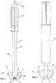
- This figurealso shows an impactor 13, comprising a handle 13a, a rod 13b and a threaded end 13c which is screwed into the threaded access hole 10.
- the impactor 13comprises, at the base of the threaded portion 13c, a hemispherical portion 13d shaped and dimensioned to be housed in the corresponding hemispherical cavity 8 of the adapter 2.
- the impactor 13makes it possible to manipulate the cup 1 during its insertion and its positioning in the acetabular cavity.
- a step of separating the adapter 2 from the cup 1has been illustrated.
- a syringe 14 containing a suitable liquid, for example physiological saline, and comprising a tip 14ais provided.
- the syringe 14then makes it possible to inject a liquid under pressure into the free space 9, causing the separation of the adapter 2 screws. to the cup 1.
- the impactor 13comprises a tubular handle: it has thus been illustrated on the figure 5 an impactor 13 comprising an axial channel 13e.
- an impactor 13comprising an axial channel 13e.
- liquid and a piston rod 13fcan be introduced into the axial channel 13e, which forces the liquid into the free space 9.
- the adapter 2comprises the hemispherical cavity 8, to fulfill the function of provisional test insert.
- an adapter 2 devoid of hemispherical cavitythen serving only as an adapter for the positioning of the cup 1 in the acetabulum cavity by an impactor 13.
- the access hole 10simultaneously serves as a means for attaching the impactor 13 to the adapter 2.
- itcould be provided in the central portion of the adapter 2 a hole for the attachment of the impactor 13, while the access hole 10 for the injection of fluid could be deported. The hole for the attachment of the impactor should then be blind.
- the gamma adapter-cup assemblyis then sterilized in a sealed protective envelope 15 ( figure 2 ). From there, the adapter-cup assembly is thus packaged in the sterile state in the sealed protective envelope 15.
- the surgeonremoves the sealed protective envelope 15, and can engage a sterile impactor 13 by screwing into the access hole 10. The surgeon can then manipulate the cup 1 through the impactor 13 and the adapter 2 fitted, printing cup 1 all the mechanical forces necessary for its positioning and orientation.
- the surgeoncan adapt a ball head in the hemispherical cavity 8 of the adapter 2 of the temporary insert type, which then serves as a temporary test insert.
- the surgeoncan remove the temporary insert 2 away from the cup 1 by introducing a liquid or other fluid under pressure, by means of a syringe 14 as illustrated on the drawing. figure 6 , or in the impactor 13 with rod-piston 13f and axial channel 13e as illustrated in FIG. figure 5 .
Landscapes
- Health & Medical Sciences (AREA)
- Orthopedic Medicine & Surgery (AREA)
- Transplantation (AREA)
- Heart & Thoracic Surgery (AREA)
- Life Sciences & Earth Sciences (AREA)
- Oral & Maxillofacial Surgery (AREA)
- Engineering & Computer Science (AREA)
- Biomedical Technology (AREA)
- Veterinary Medicine (AREA)
- Vascular Medicine (AREA)
- Cardiology (AREA)
- Animal Behavior & Ethology (AREA)
- General Health & Medical Sciences (AREA)
- Public Health (AREA)
- Physical Education & Sports Medicine (AREA)
- Prostheses (AREA)
- Surgical Instruments (AREA)
Abstract
Description
Translated fromFrenchLa présente invention concerne les instruments de pose d'un cotyle prothétique destiné à remplacer le cotyle naturel de la hanche.The present invention relates to instruments for fitting a prosthetic acetabulum to replace the natural acetabulum of the hip.
Une prothèse totale de hanche comprend deux parties constituant une articulation à rotule, à savoir une partie femelle destinée à remplacer le cotyle naturel de la hanche et une partie mâle destinée à remplacer la tête du fémur.A total hip prosthesis comprises two parts constituting a ball joint, namely a female part intended to replace the natural acetabulum of the hip and a male part intended to replace the head of the femur.
La partie mâle de l'articulation comporte généralement une tige, destinée à pénétrer dans le canal médullaire du fémur, et dont l'extrémité proximale se raccorde par un col à une tête sphérique destinée à pénétrer dans le cotyle.The male part of the joint generally comprises a rod, intended to penetrate the medullary canal of the femur, and whose proximal end is connected by a neck to a spherical head intended to penetrate the acetabulum.
La partie femelle de l'articulation, qui doit remplacer le cotyle naturel de la hanche, et que l'on désignera globalement par l'appellation cotyle, comprend habituellement une cupule hémisphérique métallique à face proximale convexe et face distale concave, la face proximale convexe venant se loger dans une cavité cotyloïdienne préparée de l'os du bassin, la face distale concave recevant la face proximale convexe hémisphérique d'un insert en une matière plastique à faible coefficient de frottement tel que le polyéthylène ou une céramique, l'insert ayant lui-même une cavité distale hémisphérique coaxiale qui reçoit la tête sphérique de la partie mâle de l'articulation.The female part of the joint, which must replace the natural acetabulum of the hip, and which will be generally referred to as the acetabulum, usually comprises a hemispherical metal cup with a convex proximal face and a concave distal surface, the convex proximal surface. accommodated in an acetabular cavity prepared from the pelvic bone, the concave distal surface receiving the hemispherical convex proximal face of an insert made of a low friction plastic material such as polyethylene or a ceramic, the insert having itself a coaxial hemispherical distal cavity that receives the spherical head of the male part of the joint.
On a déjà prévu des prothèses à simple mobilité, dans lesquelles l'insert en polyéthylène ou en céramique est fixe dans la face distale concave de la cupule métallique, les mouvements de rotation de l'articulation se faisant entre la tête sphérique de la partie mâle de prothèse et la cavité distale hémisphérique de l'insert.It has already provided for single mobility prostheses, in which the polyethylene or ceramic insert is fixed in the concave distal face of the metal cup, the rotational movements of the joint being between the spherical head of the male part. prosthesis and the hemispherical distal cavity of the insert.
On a par ailleurs déjà proposé des prothèses à double mobilité, dans lesquelles l'insert en polyéthylène ou en céramique a lui-même une capacité de rotation dans la face distale concave de la cupule métallique, de sorte que les mouvements de rotation de l'articulation se font d'une part entre la face proximale convexe de l'insert et la face distale concave de la cupule métallique, et d'autre part entre la cavité distale hémisphérique de l'insert et la tête sphérique de partie mâle d'articulation.It has also been proposed dual mobility prostheses, in which the polyethylene or ceramic insert itself has a rotational capacity in the concave distal face of the metal cup, so that the rotational movements of the articulation are made on the one hand between the convex proximal face of the insert and the concave distal face of the metal cup, and on the other hand between the hemispherical distal cavity of the insert and the spherical head of the male articulation part. .
Dans tous les cas, l'une des difficultés réside dans le positionnement et la fixation de la cupule métallique dans la cavité cotyloïdienne de l'os. La qualité de l'adaptation et de la fixation de la cupule dans la cavité cotyloïdienne est en effet essentielle pour la longévité de la prothèse, c'est-à-dire pour la durabilité de la liaison entre l'os et la cupule métallique.In all cases, one of the difficulties lies in the positioning and fixation of the metal cup in the acetabular cavity of the bone. The quality of the adaptation and fixation of the cup in the acetabular cavity is indeed essential for the longevity of the prosthesis, that is to say for the durability of the connection between the bone and the metal cup.
Ainsi, lors de la pose de la cupule dans la cavité cotyloïdienne, il faut pouvoir utiliser un impacteur qui permet d'appliquer une force d'enfoncement de la cupule dans la cavité cotyloïdienne de l'os, qui permet d'appliquer des couples de rotation pour régler l'orientation de la cupule, et qui permet de maintenir la cupule en position fixe pendant une durée suffisante notamment pour la prise d'un ciment entre la face proximale convexe de la cupule et la cavité cotyloïdienne de l'os. Il faut ensuite pouvoir retirer l'impacteur sans exercer d'effort sur la cupule, afin de ne pas dégrader la qualité de sa fixation dans la cavité cotyloïdienne.Thus, during the placement of the cup in the acetabular cavity, it must be possible to use an impactor that allows to apply a force of depression of the cup in the acetabular cavity of the bone, which allows to apply pairs of rotation to adjust the orientation of the cup, and which keeps the cup in a fixed position for a sufficient period of time including for taking a cement between the convex proximal surface of the cup and the acetabulum cavity of the bone. It must then be possible to remove the impactor without exerting force on the cup, so as not to degrade the quality of its fixation in the acetabulum.
Mais, notamment pour les prothèses à double mobilité dans lesquelles la face distale concave de la cupule constitue une surface de glissement qui doit être parfaitement lisse, et qui est pour cela généralement polie miroir, pour un pivotement libre de l'insert dans la cupule, il faut éviter tout risque de dégradation de cette face distale concave de cupule par les instruments de pose de la cupule dans la cavité cotyloïdienne. Par exemple, un instrument radialement expansible et rétractible, qui prendrait appui en plusieurs zones discontinues de la face distale concave de cupule pour tenir la cupule au moment de la pose, conduirait nécessairement soit à une déformation permanente et localisée de la face distale concave de la cupule, soit à un maintien insuffisant, de sorte que ce type de maintien n'est pas acceptable.But especially for dual mobility prostheses in which the concave distal face of the cup is a sliding surface which must be perfectly smooth, and which is therefore generally polished mirror for free pivoting of the insert in the cup, it is necessary to avoid any risk of degradation of this distal concave cup face by the instruments for placing the cup in the acetabulum. For example, a radially expandable and retractable instrument, which would support in several discontinuous areas of the concave distal cup face to hold the cup at the time of insertion, would necessarily lead to either a permanent and localized distortion of the concave distal face of the cup. cup, or to an insufficient maintenance, so that this type of maintenance is not acceptable.
Le document
Le document
On a imaginé divers autres moyens pour tenir la cupule sans prendre appui sur sa face distale concave. Un premier moyen consiste à tenir la cupule par sa lèvre circulaire, et par la partie adjacente de sa surface externe. Mais cela conduit à dégrader localement l'os dans la zone de maintien autour de la cupule, ce qui fragilise le maintien ultérieur de la cupule dans l'os.Various other means have been devised for holding the cup without bearing on its concave distal surface. A first way is to hold the cup by its circular lip, and the adjacent portion of its outer surface. But this leads to locally degrade the bone in the holding zone around the cup, which weakens the subsequent maintenance of the cup in the bone.
Le document
Le document
Le document
Ainsi, les instruments de pose de cupule actuellement connus ne permettent pas un maintien satisfaisant de la cupule pour une libre orientation et un appui suffisant de la cupule dans l'os, sans dégrader la cupule ou l'os adjacent.Thus, the currently known cup placement instruments do not allow satisfactory maintenance of the cup for free orientation and sufficient support of the cup in the bone, without degrading the cup or the adjacent bone.
Après la pose de la cupule dans la cavité cotyloïdienne, le chirurgien a généralement besoin d'adapter dans la cupule un insert d'essai, ayant sensiblement la même forme que l'insert définitif de la prothèse, et destiné à recevoir en une ou plusieurs fois des parties mâles d'articulation. Cela permet au chirurgien de tester plusieurs tailles de partie mâle d'articulation, et de faire les essais de mouvement. Le but est de permettre au chirurgien de choisir la taille la plus appropriée de partie mâle d'articulation, en fonction de la morphologie du patient. Et il enlève ensuite l'insert d'essai, pour adapter l'insert définitif dans lequel viendra se loger la tête d'articulation mâle choisie.After placing the cup in the acetabular cavity, the surgeon generally needs to fit into the cup a test insert, having substantially the same shape as the final insert of the prosthesis, and intended to receive in one or more times male parts of articulation. This allows the surgeon to test several sizes of male joint part, and to do the movement tests. The goal is to allow the surgeon to choose the most appropriate size of male joint part, depending on the morphology of the patient. And it then removes the test insert, to adapt the final insert in which will be housed the chosen male joint head.
Pour ces opérations, en utilisant les dispositifs décrits dans les documents mentionnés ci-dessus, le chirurgien doit donc disposer d'un nombre assez important de pièces à assembler, chaque pièce devant être stérile : une cupule cotyloïdienne, un insert d'essai, un insert définitif, plusieurs parties mâles de prothèse, et des instruments complexes pour tenir la cupule pendant sa pose. En particulier, aucun des documents ci-dessus ne décrit ni ne permet de donner à la tête d'impacteur une fonction d'insert d'essai pouvant recevoir une tête fémorale.For these operations, using the devices described in the documents mentioned above, the surgeon must have a large number of parts to assemble, each piece to be sterile: an acetabulum cup, a test insert, a definitive insert, several male prosthesis parts, and complex instruments to hold the cup during its installation. In particular, none of the above documents describes or allows to give the impactor head a test insert function that can receive a femoral head.
Considérant que les patients ont des tailles diverses, le chirurgien doit nécessairement disposer d'un stock assez important de pièces, ce qui augmente le coût d'immobilisation de l'ensemble.Considering that the patients have various sizes, the surgeon must necessarily have a fairly large stock of parts, which increases the cost of immobilization of the whole.
Le problème proposé par la présente invention est d'éviter les inconvénients des instruments connus de pose de cotyle, en proposant une nouvelle structure d'instruments qui assure à la fois une tenue mécaniquement résistante de la cupule sur un impacteur pour la manipulation et la pose de la cupule dans une cavité cotyloidienne, et une absence totale de déformation ou de dégradation de la face distale concave de la cupule par les instruments.The problem proposed by the present invention is to avoid the drawbacks of known acetabulum-fitting instruments, by proposing a new instrument structure which ensures both a mechanically resistant cup-shaped resistance on an impactor for handling and fitting. of the cup in an acetabular cavity, and a total absence of deformation or degradation of the concave distal face of the cup by the instruments.
Avec les moyens selon l'invention, on doit pouvoir impacter la cupule dans la cavité cotyloïdienne, l'orienter de manière précise et satisfaisante, et la fixer correctement dans la cavité cotyloïdienne, sans détériorer la surface distale concave de glissement de la cupule, et sans aucune excroissance de surface externe de la cupule ni dégradation de la zone périphérique d'os autour de la cupule.With the means according to the invention, it must be possible to impact the cup in the acetabulum, to guide it precisely and satisfactorily, and to fix it correctly in the acetabular cavity, without damaging the concave distal sliding surface of the cup, and without any outgrowth of the outer surface of the cup or degradation of the peripheral zone of bone around the cup.
Les moyens selon l'invention doivent pouvoir s'appliquer indifféremment à des prothèses à simple mobilité et à des prothèses à double mobilité.The means according to the invention must be able to be applied indifferently to prostheses with simple mobility and to prostheses with double mobility.
Un autre but de l'invention est de réduire le nombre de pièces stériles que le chirurgien doit assembler lors de la pose d'une prothèse. On peut ainsi réduire les stocks d'instruments, et faciliter le travail du chirurgien, en réduisant les risques opératoires.Another object of the invention is to reduce the number of sterile parts that the surgeon must assemble during the installation of a prosthesis. It is thus possible to reduce the stocks of instruments, and to facilitate the work of the surgeon, by reducing the operational risks.
Selon un autre but de l'invention, les instruments doivent pouvoir être séparés de la cupule sans appliquer à la cupule un effort mécanique tendant à la déplacer par translation ou rotation vis-à-vis de l'os dans lequel elle est fixée, de façon à garantir une bonne qualité de fixation de la cupule dans l'os.According to another object of the invention, the instruments must be able to be separated from the cup without applying to the cup a mechanical force tending to move it by translation or rotation vis-à-vis the bone in which it is fixed, of to ensure a good quality of fixation of the cup in the bone.
Pour atteindre ces buts ainsi que d'autres, l'invention propose un ensemble de moyens pour la pose de cotyle, comprenant une cupule limitée par une face proximale convexe, par une face distale concave à surface de glissement, et par une lèvre périphérique, et comprenant un adaptateur pour solidariser la cupule sur un impacteur, l'adaptateur comportant :
- des moyens de fixation, pour fixer de manière détachable l'adaptateur sur l'impacteur,
- des moyens de fixation sur la cupule, laissant un espace libre entre l'adaptateur et la cupule une fois l'adaptateur fixé à la cupule,
- un trou d'accès mettant en communication avec l'extérieur l'espace libre entre l'adaptateur et la cupule,
- la cupule comprend, sur sa face distale concave, une surface annulaire de retenue, cylindrique ou légèrement conique, prolongeant la surface de glissement vers la lèvre périphérique,
- l'adaptateur comprend une surface annulaire d'engagement, cylindrique ou légèrement conique et conforme à la surface annulaire de retenue de la cupule,
- de sorte que l'adaptateur peut être retenu en force de façon étanche avec sa surface annulaire d'engagement serrée radialement dans la surface annulaire de retenue de la cupule.
- fastening means for releasably securing the adapter to the impactor,
- fastening means on the cup, leaving a free space between the adapter and the cup once the adapter is attached to the cup,
- an access hole communicating with the outside the free space between the adapter and the cup,
- the cup comprises, on its concave distal surface, an annular retaining surface, cylindrical or slightly conical, extending the sliding surface towards the peripheral lip,
- the adapter comprises an annular engagement surface, cylindrical or slightly conical and conforming to the annular retaining surface of the cup,
- so that the adapter can be retained in force in a sealed manner with its radially tight annular engagement surface in the annular retaining surface of the cup.
Par le fait que l'adaptateur est conformé pour être retenu en force de façon étanche selon sa périphérie dans la cupule, il est en appui sur la face distale concave de cupule selon la seule surface annulaire de retenue, à l'écart de la surface de glissement, évitant de produire toute irrégularité sur la surface de glissement de la cupule.In that the adapter is designed to be retained in force sealingly around its periphery in the cup, it is supported on the distal concave cup surface according to the single annular retaining surface, away from the surface slip, avoiding any irregularity on the sliding surface of the cup.
D'autre part, grâce au fait qu'il reste un espace libre entre l'adaptateur et la cupule une fois l'adaptateur retenu en force de façon étanche selon sa surface annulaire d'engagement dans la cupule, et par le fait que l'adaptateur comporte un trou d'accès, on peut retirer ultérieurement l'adaptateur à l'écart de la cupule en injectant par le trou d'accès un fluide sous pression, avantageusement un liquide sous pression, dans l'espace libre entre l'adaptateur et la cupule. Le fluide sous pression produit une force résultante d'éjection axiale symétrique de l'adaptateur à l'écart de la cupule, et produit sur la surface de glissement de la cupule une contrainte mécanique régulièrement répartie par le fait que cette contrainte est une pression de fluide. On évite ainsi à nouveau toute déformation localisée de la surface de glissement de la cupule, et on évite toute contrainte de traction, d'oscillation ou de rotation sur la cupule.On the other hand, thanks to the fact that there remains a free space between the adapter and the cup once the adapter retained in force sealingly along its annular engagement surface in the cup, and by the fact that the adapter has an access hole, the adapter can be withdrawn away from the cup by injecting through the access hole a pressurized fluid, advantageously a liquid under pressure, into the free space between the adapter and the cup. The pressurized fluid produces a resultant force of symmetrical axial ejection of the adapter away from the cup, and produces on the sliding surface of the cup a mechanical stress regularly distributed by the fact that this stress is a pressure of fluid. This avoids any localized deformation of the sliding surface of the cup and avoids any tensile stress, oscillation or rotation on the cup.
Le blocage en force de l'adaptateur dans la cupule peut suffire pour assurer une solidarisation forte de l'adaptateur, et donc une solidarisation forte de la cupule sur l'impacteur.Blocking the force of the adapter in the cup may be sufficient to ensure strong attachment of the adapter, and therefore a strong solidarity of the cup on the impactor.
On pourra toutefois préférer prévoir en outre, sur l'adaptateur, des moyens de butée destinés à venir en appui axial sur la lèvre périphérique de la cupule pour limiter la pénétration de l'adaptateur dans la cupule. De la sorte, l'impacteur peut appliquer à l'adaptateur une force d'impaction supérieure, force qui est transmise à la cupule d'une part par la surface annulaire d'engagement de l'adaptateur dans la cupule, et d'autre part par les butées en appui sur la lèvre périphérique de la cupule.However, it may be preferable to further provide, on the adapter, stop means for pressing axially on the peripheral lip of the cup to limit the penetration of the adapter into the cup. In this way, the impactor can apply to the adapter a higher impaction force force that is transmitted to the cup on the one hand by the annular surface of engagement of the adapter in the cup, and other part by the abutments resting on the peripheral lip of the cup.
Une solidarisation encore améliorée de la cupule sur l'adaptateur peut avantageusement être obtenue en prévoyant que la surface annulaire de retenue de la cupule comprend au moins une rainure annulaire, et la surface annulaire d'engagement de l'adaptateur comprend au moins une nervure annulaire correspondante apte à s'engager dans la rainure annulaire. La profondeur des rainures et nervures sera choisie relativement faible, pour améliorer la solidarisation sans toutefois compromettre la séparation ultérieure de l'adaptateur à l'écart de la cupule.Further improved attachment of the cup to the adapter can advantageously be obtained by providing that the annular retaining surface of the cup comprises at least one annular groove, and the annular engagement surface of the adapter comprises at least one annular rib. corresponding to engage in the annular groove. The depth of the grooves and ribs will be chosen relatively low, to improve the joining without compromising the subsequent separation of the adapter away from the cup.
De préférence, la cupule peut comprendre une surface de glissement sensiblement hémisphérique avantageusement polie miroir, prolongée par une surface annulaire de retenue cylindrique ou légèrement conique courte. De la sorte, l'adaptateur peut prendre appui sur la surface annulaire de retenue, qui n'est pas une surface de glissement de la cupule, de sorte que l'on réduit les contraintes mécaniques appliquées sur la surface hémisphérique de glissement.Preferably, the cup may comprise a substantially hemispherical sliding surface advantageously polished mirror, extended by a cylindrical retaining surface or slightly short conical. In this way, the adapter can be supported on the annular retaining surface, which is not a sliding surface of the cup, so that the mechanical stresses applied on the hemispherical sliding surface are reduced.
L'adaptateur peut être solidarisé à l'impacteur par tous moyens. Toutefois, on pourra préférer des moyens de fixation de l'adaptateur sur l'impacteur comprenant un trou de fixation taraudé pratiqué dans l'adaptateur, permettant le vissage d'une portion filetée correspondante de l'impacteur. Si le trou de fixation diffère du trou d'accès, il doit être borgne.The adapter can be secured to the impactor by any means. However, it may be preferred means for fixing the adapter on the impactor comprising a tapped mounting hole made in the adapter, allowing the screwing of a corresponding threaded portion of the impactor. If the mounting hole differs from the access hole, it must be blind.
L'adaptateur selon l'invention est utilisé comme moyen de liaison entre l'impacteur et la cupule.The adapter according to the invention is used as a connecting means between the impactor and the cup.
Toutefois, on peut avantageusement donner à l'adaptateur une seconde fonction, à savoir une fonction d'insert provisoire d'essai, en prévoyant un adaptateur qui comprend, sur sa face distale, une cavité hémisphérique dimensionnée pour permettre l'engagement d'une tête de prothèse fémorale. La cavité hémisphérique peut être concentrique avec la face proximale convexe de l'adaptateur, en particulier pour les prothèses à double mobilité. On comprend que cela réduit le nombre de pièces à assembler par le chirurgien pour la pose de la prothèse, puisqu'il n'y a plus besoin d'un insert d'essai spécifique distinct de l'adaptateur.However, it is advantageous to give the adapter a second function, namely a temporary test insert function, by providing an adapter which comprises, on its distal face, a hemispherical cavity sized to allow the engagement of a femoral prosthesis head. The hemispherical cavity may be concentric with the convex proximal face of the adapter, particularly for dual mobility prostheses. It is understood that this reduces the number of parts to be assembled by the surgeon for fitting the prosthesis, since there is no longer a specific test insert separate from the adapter.
Le trou d'accès à l'espace libre entre la cupule et l'adaptateur est avantageusement conformé et dimensionné pour y engager l'extrémité d'une seringue de façon étanche. De la sorte, le fluide sous pression peut être injecté par une simple seringue, instrument qui est généralement à la disposition du chirurgien, sans que cela nécessite un appareillage supplémentaire.The access hole to the free space between the cup and the adapter is advantageously shaped and dimensioned to engage the end of a syringe sealingly. In this way, the fluid under pressure can be injected by a simple syringe, an instrument that is generally available to the surgeon, without this requiring additional equipment.
De préférence, le trou d'accès de l'adaptateur peut être taraudé pour remplir simultanément la fonction de trou de fixation de l'adaptateur en permettant le vissage d'une portion filetée correspondante de l'impacteur dans l'adaptateur.Preferably, the access hole of the adapter can be threaded to simultaneously fulfill the function of fixing hole of the adapter by allowing the screwing of a corresponding threaded portion of the impactor in the adapter.
Le trou d'accès de l'adaptateur peut alors avantageusement être localisé dans le fond d'une cavité hémisphérique dimensionnée pour permettre l'engagement d'une tête de prothèse fémorale.The access hole of the adapter can then advantageously be located in the bottom of a hemispherical cavity dimensioned to allow the engagement of a femoral prosthesis head.
Comme dans les prothèses connues, l'adaptateur de type insert d'essai peut être en polyéthylène. L'insert définitif peut par contre être en polyéthylène ou en céramique.As in known prostheses, the test insert type adapter may be polyethylene. The definitive insert can instead be polyethylene or ceramic.
On prévoit en outre un impacteur ayant une portion filetée pour se visser dans un trou de fixation taraudé prévu sur l'adaptateur.An impactor having a threaded portion is also provided for screwing into a threaded fastening hole provided on the adapter.
De préférence, l'impacteur peut comporter en outre, à la base de la portion filetée, une portion hémisphérique conformée et dimensionnée pour se loger dans une cavité hémisphérique correspondante de l'adaptateur. On répartit ainsi de manière plus régulière les contraintes mécaniques entre l'impacteur et l'adaptateur, contraintes relativement importantes qui apparaissent lors de l'impaction de la cupule dans la cavité cotyloïdienne.Preferably, the impactor may further comprise, at the base of the threaded portion, a hemispherical portion shaped and dimensioned to be housed in a corresponding hemispherical cavity of the adapter. The mechanical stresses between the impactor and the adapter are thus more evenly distributed, relatively large stresses occurring during the impaction of the cup in the acetabulum.
Selon l'invention, on peut avantageusement concevoir de distribuer au chirurgien un adaptateur de type insert provisoire d'essai préalablement bloqué en force de façon étanche selon sa surface annulaire d'engagement dans la surface annulaire de retenue de la cupule, l'ensemble pouvant avantageusement être conditionné à l'état stérile dans une enveloppe protectrice étanche.According to the invention, it is advantageously conceivable to distribute to the surgeon an adapter type temporary test insert previously sealed in force in a sealed manner along its annular engagement surface in the annular retaining surface of the cup, the assembly can advantageously be packaged in the sterile state in a sealed protective envelope.
Lors de l'assemblage de l'adaptateur et de la cupule, assemblage qui peut être réalisé en usine de production, on peut avantageusement utiliser la succession des étapes suivantes :
- a) refroidir l'adaptateur afin d'en diminuer les dimensions,
- b) positionner l'adaptateur dans la cupule,
- c) revenir à température ambiante pour dilater l'adaptateur une fois en place dans la cupule, l'adaptateur se trouvant ainsi bloqué en force de façon étanche selon sa surface annulaire d'engagement dans la surface annulaire de retenue de la cupule.
- a) cool the adapter to reduce its size,
- b) position the adapter in the cup,
- c) return to ambient temperature to expand the adapter once in place in the cup, the adapter thus being sealed in force against its annular engagement surface in the annular retaining surface of the cup.
On prévoit en outre de préférence une étape de stérilisation par rayons gamma de l'adaptateur et de la cupule une fois solidarisés.It is further preferably provided a gamma sterilization step of the adapter and the cup once secured.
Après la pose de la cupule, on peut séparer l'adaptateur à l'écart de la cupule par une étape au cours de laquelle on injecte par le trou d'accès un fluide sous pression, avantageusement un liquide sous pression, dans l'espace libre entre l'adaptateur et la cupule.After the cup has been placed, the adapter can be separated from the cup by a step during which a pressurized fluid, advantageously a liquid under pressure, is injected into the space through the access hole. free between the adapter and the cup.
D'autres objets, caractéristiques et avantages de la présente invention ressortiront de la description suivante de modes de réalisation particuliers, faite en relation avec les figures jointes, parmi lesquelles :
- la
figure 1 est une vue en perspective d'un ensemble selon un mode de réalisation de l'invention, comprenant une cupule cotyloïdienne dans laquelle est engagé en force un adaptateur de type insert provisoire d'impaction et d'essai ; - la
figure 2 est une vue de côté de l'ensemble de lafigure 1 , inséré dans une enveloppe protectrice étanche ; - la
figure 3 est une vue de face de l'ensemble de lafigure 1 ; - la
figure 4 est une vue de côté en coupe diamétrale selon le plan A-A de lafigure 3 ; - la
figure 5 est une vue de côté en coupe montrant un impacteur engagé dans l'insert provisoire de l'ensemble insert-cupule de lafigure 4 ; et - la
figure 6 est une vue de côté en coupe illustrant une seringue engagée dans le passage de l'insert provisoire dans un ensemble insert-cupule selon l'invention.
- the
figure 1 is a perspective view of an assembly according to one embodiment of the invention, comprising an acetabulum cup in which is engaged in force a temporary type of impaction and test insert adapter; - the
figure 2 is a side view of the whole of thefigure 1 , inserted in a waterproof protective envelope; - the
figure 3 is a front view of the whole of thefigure 1 ; - the
figure 4 is a side view in diametrical section along the plane AA of thefigure 3 ; - the
figure 5 is a sectional side view showing an impactor engaged in the temporary insert of the insert-cupule assembly of thefigure 4 ; and - the
figure 6 is a sectional side view illustrating a syringe engaged in the passage of the temporary insert in an insert-cup assembly according to the invention.
Dans le mode de réalisation illustré sur les
La cupule 1 constitue la cupule définitive destinée à être fixée dans une cavité cotyloïdienne de l'os du bassin.The
Par contre, l'adaptateur 2 a au moins la fonction de pièce intermédiaire entre la cupule 1 et un impacteur qui sert à manipuler la cupule 1 lors de sa pose dans la cavité cotyloïdienne, et l'adaptateur 2 est destiné à être ensuite remplacé par un insert définitif.On the other hand, the
La cupule 1 est une hémisphère à paroi relativement mince, ayant une face proximale convexe 3, mieux visible sur la
La surface hémisphérique 5a de la cupule 1 est parfaitement lisse et régulière, de préférence polie miroir; afin de constituer une surface de glissement dans laquelle peut pivoter parfaitement un insert définitif hémisphérique ultérieurement introduit dans la cupule 1 après sa pose dans la cavité cotyloïdienne.The
L'adaptateur 2 présente une forme générale arrondie limitée par une face proximale convexe 7 et une face distale 11 à cavité hémisphérique 8.The
La face proximale convexe 7 de l'adaptateur 2 comprend une surface annulaire d'engagement 7a cylindrique ou légèrement conique, et une calotte centrale 7b qui reste en retrait de la forme hémisphérique constituée par la surface hémisphérique 5a de glissement de la cupule 1. De la sorte, il reste un espace libre 9 entre l'insert provisoire 2 et la cupule 1 en position emmanchée telle qu'illustrée sur la
La surface annulaire d'engagement 7a présente une forme qui correspond à celle de la surface annulaire de retenue 5b, et un diamètre tel qu'elle est retenue en force dans la surface annulaire de retenue 5b de la cupule 1, de sorte que l'adaptateur 2 et la cupule 1 puissent constituer un sous-ensemble solidaire capable de supporter, sans mouvement relatif de l'un par rapport à l'autre, des contraintes mécaniques élevées, supérieures aux efforts qu'il faut appliquer à une cupule lors de sa pose dans la cavité cotyloïdienne.The
Sur les
En alternative, dans le mode de réalisation de la
La cavité hémisphérique 8 de l'adaptateur 2 est dimensionnée pour recevoir une tête de rotule de partie mâle d'articulation fémorale. De la sorte, l'adaptateur 2 peut constituer un insert provisoire d'essai.The
Dans le fond de l'adaptateur 2, on prévoit un trou d'accès 10 qui met en communication avec l'extérieur l'espace libre 9 entre l'adaptateur 2 et la cupule 1.In the bottom of the
La face distale 11 de l'adaptateur 2 est bordée d'une nervure périphérique 12 circulaire qui constitue un moyen de butée venant en appui sur la lèvre périphérique 6 de la cupule 1 en position emmanchée illustrée sur la
On considère maintenant la
Sur cette figure, on a également représenté un impacteur 13, comprenant un manche 13a, une tige 13b et une extrémité filetée 13c qui vient se visser dans le trou d'accès 10 fileté. De préférence, l'impacteur 13 comporte, à la base de la portion filetée 13c, une portion hémisphérique 13d conformée et dimensionnée pour se loger dans la cavité hémisphérique correspondante 8 de l'adaptateur 2. Ainsi, l'impacteur 13 permet de manipuler la cupule 1 lors de son insertion et de son positionnement dans la cavité cotyloïdienne.This figure also shows an impactor 13, comprising a
Sur la
En alternative, pour éviter d'utiliser une seringue supplémentaire, on peut prévoir que l'impacteur 13 comprend un manche tubulaire : on a illustré ainsi sur la
Dans le mode de réalisation illustré sur les figures, l'adaptateur 2 comporte la cavité hémisphérique 8, pour remplir la fonction d'insert provisoire d'essai. On pourra toutefois, sans sortir du cadre de l'invention, prévoir un adaptateur 2 dépourvu de cavité hémisphérique, servant alors uniquement d'adaptateur pour le positionnement de la cupule 1 dans la cavité cotyloïdienne par un impacteur 13.In the embodiment illustrated in the figures, the
Egalement, dans le mode de réalisation illustré, le trou d'accès 10 sert simultanément de moyen de fixation de l'impacteur 13 sur l'adaptateur 2. En alternative, on pourrait prévoir dans la partie centrale de l'adaptateur 2 un trou pour la fixation de l'impacteur 13, tandis que le trou d'accès 10 pour l'injection de fluide pourrait être déporté. Le trou pour la fixation de l'impacteur devrait alors être borgne.Also, in the illustrated embodiment, the
L'utilisation des instruments selon l'invention est expliquée ci-après.The use of the instruments according to the invention is explained below.
En usine, on peut assembler l'adaptateur 2 dans la cupule 1 par une procédure-comprenant les étapes :
- a) on
refroidit l'adaptateur 2 à une température suffisamment basse pour en diminuer légèrement les dimensions, lesdites dimensions étant initialement telles que le diamètre de la surface annulaire d'engagement 7a de l'adaptateur 2 soit légèrement plus grand que le diamètre de la surface annulaire de retenue 5b de la cupule 1 à la même température. En abaissant la température de l'adaptateur 2, on réduit son diamètre externe, afin de faciliter son engagement à l'entrée de la cupule 1 elle-même conservée à température ambiante ; - b) on positionne alors l'adaptateur 2 dans
la cupule 1, jusqu'à venir en butée par la nervure périphérique 12 contre la lèvre périphérique 6 ; - c) on revient à température ambiante pour laisser dilater l'adaptateur 2 une fois en place dans
la cupule 1, l'adaptateur 2 se trouvant ainsi emmanché et retenu en force de façon étanche selon sa surface annulaire d'engagement 7a dans la cupule 1.
- a) the
adapter 2 is cooled to a sufficiently low temperature to slightly reduce its dimensions, said dimensions being initially such that the diameter of theannular engagement surface 7a of theadapter 2 is slightly larger than the diameter of theannular retaining surface 5b of thecup 1 at the same temperature. By lowering the temperature of theadapter 2, the outer diameter thereof is reduced, in order to facilitate its engagement with the inlet of thecup 1, itself kept at ambient temperature; - b) the
adapter 2 is then positioned in thecup 1, until it comes into abutment with theperipheral rib 12 against theperipheral lip 6; - c) it returns to room temperature to allow the
adapter 2 to expand once in place in thecup 1, theadapter 2 thus being fitted and retained in force in a sealed manner along itsannular engagement surface 7a in thecup 1 .
On stérilise ensuite l'ensemble adaptateur-cupule par rayons gamma, dans une enveloppe protectrice étanche 15 (
Sur le lieu d'utilisation, c'est-à-dire dans la salle d'opération, le chirurgien retire l'enveloppe protectrice étanche 15, et peut engager un impacteur 13 stérile par vissage dans le trou d'accès 10. Le chirurgien peut ensuite manipuler la cupule 1 grâce à l'impacteur 13 et à l'adaptateur 2 emmanché, imprimant à la cupule 1 tous les efforts mécaniques nécessaires pour son positionnement et son orientation.At the place of use, that is to say in the operating room, the surgeon removes the sealed
Le chirurgien retire ensuite l'impacteur 13 par dévissage.The surgeon then removes the impactor 13 by unscrewing.
Ensuite, le chirurgien peut adapter une tête de rotule dans la cavité hémisphérique 8 de l'adaptateur 2 de type insert provisoire, qui sert alors d'insert provisoire d'essai.Then, the surgeon can adapt a ball head in the
Une fois la partie mâle de prothèse choisie, le chirurgien peut retirer l'insert provisoire 2 à l'écart de la cupule 1 par introduction d'un liquide ou autre fluide sous pression, au moyen d'une seringue 14 comme illustré sur la
Il adapte ensuite un insert définitif, dans la cupule 1 elle-même en place dans une cavité cotyloïdienne.He then adapts a definitive insert in the
Toutes ces opérations ont été effectuées sans risque de déformation de la surface hémisphérique 8 de glissement de la cupule 1, et sans effort parasite sur la cupule 1.All these operations were performed without risk of deformation of the
La présente invention n'est pas limitée aux modes de réalisation qui ont été explicitement décrits, mais elle en inclut les diverses variantes et généralisations contenues dans le domaine des revendications ci-après.The present invention is not limited to the embodiments which have been explicitly described, but it includes the various variants and generalizations thereof within the scope of the claims below.
Claims (17)
- Set of acetabular cup prosthesis setting means, comprising a cup (1) delimited by a convex proximal face (3), a concave distal face (5) with a sliding surface (5a), and a peripheral lip (6), and further comprising an adapter (2) for fastening the cup (1) to an impactor (13), the adapter (2) including:- fixing means (10, 10a) for detachably fixing the adapter (2) to the impactor (13),- fixing means on the cup (1), leaving a free space (9) between the adapter (2) and the cup (1) once the adapter (2) is fixed to the cup (1),- an access hole (10) through which the free space (9) between the adapter (2) and the cup (1) communicates with the outside,- the cup (1) comprises, on its concave distal face (5), a cylindrical or slightly conical annular retaining surface (5b) extending the sliding surface (5a) toward the peripheral lip (6),characterized in that:- the adapter (2) comprises a cylindrical or slightly conical annular engagement surface (7a) the same shape as the annular retaining surface (5b) of the cup (1),- with the result that the adapter (2) may be forcibly retained in fluid-tight manner with its annular engagement surface (7a) gripped radially in the annular retaining surface (5b) of the cup (1).
- Set according to claim 1,characterized in that the adapter (2) comprises abutment means (12) adapted to bear axially on the peripheral lip (6) of the cup (1) to limit the penetration of the adapter (2) into the cup (1).
- Set according to either of claims 1 or 2,characterized in that the sliding surface (5a) of the cup (1) is substantially hemispherical, extended by a short cylindrical or slightly conical annular retaining surface (5b).
- Set according to any one of claims 1 to 3,characterized in that the annular retaining surface (5b) of the cup (1) comprises at least one annular groove (5c) and the annular engagement surface (7a) of the adapter (2) comprises at least one corresponding annular rib (7c) adapted to be engaged in the annular groove (5c).
- Set according to any one of claims 1 to 4,characterized in that the means for fixing the adapter (2) to the impactor (13) comprise a threaded fixing hole (10) in the adapter (2) for screwing in a corresponding threaded portion (13c) of the impactor (13).
- Set according to any one of claims 1 to 5,characterized in that the access hole (10) to the free space (9) between the cup (1) and the adapter (2) is conformed and dimensioned for the fluid-tight engagement therein of the end (14a) of a syringe (14).
- Set according to any one of claims 1 to 6,characterized in that the access hole (10) of the adapter (2) is threaded (10a) to fulfill the function of an adapter fixing hole by enabling a corresponding threaded portion (13c) of the impactor (13) to be screwed into the adapter (2).
- Set according to claim 7,characterized in that the impactor (13) comprises a tubular handle with an axial passage (13e) into which may be introduced a liquid and a piston-rod (13f) that forces the liquid into the free space (9).
- Set according to any one of claims 1 to 8,characterized in that the adapter (2) is a temporary trial insert comprising, on its distal face (11), a hemispherical cavity (8) dimensioned to enable the engagement of the head of a femoral prosthesis.
- Set according to claim 9,characterized in that the access hole (10) of the adapter (2) is located in the bottom of the hemispherical cavity (8).
- Set according to either of claims 9 or 10,characterized in that the adapter (2) is made of polyethylene.
- Set according to any one of claims 1 to 11,characterized in that it further comprises an impactor (13) having a threaded portion (13c) for screwing into a threaded fixing hole (10) in the adapter (2).
- Set according to claim 12,characterized in that the impactor (13) further includes, at the base of the threaded portion (13c), a hemispherical portion (13d) conformed and dimensioned to be accommodated in a corresponding hemispherical cavity (8) of the adapter (2).
- Set according to any one of claims 1 to 13,characterized in that the annular engagement surface (7a) of the adapter (2) is forcibly immobilized in fluid-tight manner in the annular retaining surface (5b) of the cup (1).
- Set according to claim 14,characterized in that the adapter-cup assembly is packaged in a sterile state in a sealed protective envelope (15).
- Method of assembling an adapter (2) and a cup (1) of the set according to any one of claims 1 to 15,characterized in that it comprises the steps of:a) cooling the adapter (2) to reduce its dimensions,b) positioning the adapter (2) in the cup (1),c) allowing the adapter (2), once in place in the cup (1), to return to room temperature to expand it so that the annular engagement surface (7a) of the adapter (2) is forcibly immobilized in fluid-tight manner in the annular retaining surface (5b) of the cup (1).
- Assembly method according to claim 16,characterized in that it comprises a step of sterilizing the adapter (2) and the cup (1) by means of gamma rays once they have been fastened together.
Applications Claiming Priority (2)
| Application Number | Priority Date | Filing Date | Title |
|---|---|---|---|
| FR0410879AFR2876278B1 (en) | 2004-10-13 | 2004-10-13 | COTYL APPLICATION INSTRUMENTS |
| PCT/FR2005/002542WO2006040483A1 (en) | 2004-10-13 | 2005-10-13 | Instruments for setting acetabular cup |
Publications (2)
| Publication Number | Publication Date |
|---|---|
| EP1811928A1 EP1811928A1 (en) | 2007-08-01 |
| EP1811928B1true EP1811928B1 (en) | 2012-05-16 |
Family
ID=34952812
Family Applications (1)
| Application Number | Title | Priority Date | Filing Date |
|---|---|---|---|
| EP05809187AExpired - LifetimeEP1811928B1 (en) | 2004-10-13 | 2005-10-13 | Instruments for setting acetabular cup |
Country Status (7)
| Country | Link |
|---|---|
| US (3) | US9814603B2 (en) |
| EP (1) | EP1811928B1 (en) |
| JP (2) | JP2008515579A (en) |
| CN (1) | CN101039638B (en) |
| ES (1) | ES2388143T3 (en) |
| FR (1) | FR2876278B1 (en) |
| WO (1) | WO2006040483A1 (en) |
Families Citing this family (43)
| Publication number | Priority date | Publication date | Assignee | Title |
|---|---|---|---|---|
| US8806973B2 (en) | 2009-12-02 | 2014-08-19 | Covidien Lp | Adapters for use between surgical handle assembly and surgical end effector |
| US20090088846A1 (en) | 2007-04-17 | 2009-04-02 | David Myung | Hydrogel arthroplasty device |
| US8277457B1 (en) | 2004-12-09 | 2012-10-02 | Greatbatch Medical S.A. | Orthopaedic inserter using a collet mechanism |
| US7621921B2 (en)* | 2006-01-25 | 2009-11-24 | Symmetry Medical, Inc | Split thread orthopaedic implant impactor |
| DE102007020484A1 (en)* | 2006-05-01 | 2007-12-13 | Precimed S.A. | Insertion instrument for minimally invasive joint surgery with exchangeable thread |
| DE202006010069U1 (en)* | 2006-06-28 | 2007-11-08 | Waldemar Link Gmbh & Co. Kg | Insertion device for joint sockets of prostheses |
| FR2911062B1 (en)* | 2007-01-08 | 2009-07-03 | Thomas Gradel | COTYL WITH STERILE INTERFACE |
| US8517241B2 (en) | 2010-04-16 | 2013-08-27 | Covidien Lp | Hand-held surgical devices |
| FR2921821B1 (en)* | 2007-10-09 | 2011-03-18 | Rech S Et De Fabrication Serf Soc Et | ANCILLARY FOR DETERMINING THE DIMENSIONS AND POSITIONING OF A COTYLOID IMPLANT OF A HIP PROSTHESIS |
| US20120209396A1 (en) | 2008-07-07 | 2012-08-16 | David Myung | Orthopedic implants having gradient polymer alloys |
| WO2010017282A1 (en)* | 2008-08-05 | 2010-02-11 | Biomimedica, Inc. | Polyurethane-grafted hydrogels |
| GB0819380D0 (en)* | 2008-10-23 | 2008-11-26 | Depuy Int Ltd | A surgical instrument |
| US8398650B1 (en) | 2009-01-27 | 2013-03-19 | Greatbatch Medical S.A. | Offset cup impactor with an expandable dome for double mobility implants |
| US10420648B2 (en)* | 2009-06-10 | 2019-09-24 | Jean-Pierre LAFFAY | Acetabular prosthetic system with simplified impaction |
| FR2950525B1 (en) | 2009-09-28 | 2013-05-10 | Thomas Gradel | HIP PROTHETIC COTYL WITH EXTERNAL FASTENING |
| FR2951071B1 (en)* | 2009-10-12 | 2011-10-28 | Thomas Gradel | PROTHETIC COTYLE WITH LARGE RETENTION CAPACITY |
| EP2512354A4 (en)* | 2009-12-18 | 2015-09-09 | Biomimedica Inc | Method, device, and system for shaving and shaping of a joint |
| FR2961387B1 (en)* | 2010-06-17 | 2013-06-07 | Thomas Gradel | CERAMIC COTYL WITH EXTERNAL FASTENING |
| EP2422754B1 (en)* | 2010-08-27 | 2014-11-05 | Greatbatch Medical SA | Offset cup impactor with a grasping plate for double mobility implants |
| EP2609154B1 (en) | 2010-08-27 | 2020-04-22 | Hyalex Orthopaedics, Inc. | Hydrophobic and hydrophilic interpenetrating polymer networks derived from hydrophobic polymers and methods of preparing the same |
| CH703945A1 (en)* | 2010-10-07 | 2012-04-13 | Jossi Holding Ag | Acetabular cup and method for making a joint socket. |
| EP2476397B1 (en) | 2011-01-17 | 2015-10-21 | Greatbatch Medical SA | Straight cup impactor with lever arm |
| US9119731B2 (en) | 2011-01-17 | 2015-09-01 | Greatbach Medical S.A. | Straight cup impactor |
| CA2834937A1 (en)* | 2011-05-03 | 2012-11-08 | Smith & Nephew, Inc. | Patient-matched guides for orthopedic implants |
| EP2561835B1 (en)* | 2011-08-26 | 2016-03-16 | Greatbatch Medical SA | Straight cup impactor |
| US9028502B2 (en)* | 2011-09-23 | 2015-05-12 | Greatbatch Medical S.A. | Ceramic implant holder |
| KR20140115294A (en) | 2011-10-03 | 2014-09-30 | 바이오미메디카, 인코포레이티드 | Polymeric adhesive for anchoring compliant materials to another surface |
| KR20140113655A (en) | 2011-11-21 | 2014-09-24 | 바이오미메디카, 인코포레이티드 | Systems, devices, and methods for anchoring orthopaedic implants to bone |
| AU2012342194A1 (en)* | 2011-11-23 | 2014-07-03 | Depuy (Ireland) | Surgical instrument head and assembly including tab separation member |
| CN102908214B (en)* | 2012-09-21 | 2015-01-28 | 联合骨科器材股份有限公司 | Acetabular cup implanter |
| EP2815726B1 (en)* | 2013-06-19 | 2015-08-12 | Arthrex, Inc. | Humerus implant |
| CN112773580B (en)* | 2015-07-27 | 2024-06-18 | 黑普创新技术有限责任公司 | Ball and cup impactor for implanting hip joint prosthesis |
| US11077228B2 (en) | 2015-08-10 | 2021-08-03 | Hyalex Orthopaedics, Inc. | Interpenetrating polymer networks |
| GB2552173A (en)* | 2016-07-12 | 2018-01-17 | Susannah Germaine Clarke | Holder for acetabular cup implant |
| FR3066908B1 (en)* | 2017-05-31 | 2019-07-19 | Science Et Medecine | ORTHOPEDIC ASSEMBLY COMPRISING A CUPULE AND AN APPARATUS FOR THE PLACEMENT OF THIS CUP IN AN ANATOMIC CAVITY |
| US10869950B2 (en) | 2018-07-17 | 2020-12-22 | Hyalex Orthopaedics, Inc. | Ionic polymer compositions |
| US11103367B2 (en) | 2019-02-15 | 2021-08-31 | Encore Medical, L.P. | Acetabular liner |
| CN111150481B (en)* | 2020-01-17 | 2024-09-03 | 北京市春立正达医疗器械股份有限公司 | Acetabular cup installer |
| US20220331119A1 (en) | 2020-09-18 | 2022-10-20 | Globus Medical, Inc. | Hip arthroplasty implants |
| FR3117771B1 (en)* | 2020-12-23 | 2023-02-24 | Soc Detudes De Recherches Et De Fabrication Serf | Device for engaging a spherical head in an insert |
| US12064356B2 (en) | 2021-08-19 | 2024-08-20 | Howmedica Osteonics Corp. | Multi-size acetabular impactor |
| FR3134309B1 (en)* | 2022-04-08 | 2024-05-10 | Fx Solutions | Implant mainly made of ceramic and assembly with gripping and placement device |
| WO2025151759A1 (en)* | 2024-01-11 | 2025-07-17 | Zimmer, Inc. | Taper connection separation device and method |
Family Cites Families (24)
| Publication number | Priority date | Publication date | Assignee | Title |
|---|---|---|---|---|
| US4632111A (en)* | 1985-03-21 | 1986-12-30 | Minnesota Mining And Manufacturing Company | Acetabular cup positioning apparatus |
| US5061270A (en)* | 1991-03-18 | 1991-10-29 | Aboczky Robert I | System for orienting, inserting and impacting an acetabular cup prosthesis |
| US5169399A (en)* | 1991-10-17 | 1992-12-08 | Boehringer Mannheim Corporation | Acetabular cup impactor |
| US5320625A (en)* | 1993-01-21 | 1994-06-14 | Bertin Kim C | Apparatus and method for implanting a prosthetic acetabular cup and then testing the stability of the implant |
| US6048269A (en)* | 1993-01-22 | 2000-04-11 | Mgm Grand, Inc. | Coinless slot machine system and method |
| US5954727A (en)* | 1993-10-29 | 1999-09-21 | Howmedica Inc. | Acetabular cup positioning tool and method of positioning an acetabular cup |
| US5486181A (en)* | 1994-08-04 | 1996-01-23 | Implex Corporation | Acetabular cup, method and tool and installing the same |
| US5474560A (en)* | 1994-09-26 | 1995-12-12 | Zimmer, Inc. | Prosthetic acetabular cup inserter |
| DE29608453U1 (en)* | 1996-05-09 | 1997-09-11 | Waldemar Link GmbH & Co, 22339 Hamburg | Hip cup and surgical instrument for inserting the same |
| GB9623942D0 (en)* | 1996-11-15 | 1997-01-08 | Johnson & Johnson Professional | Extraction device |
| DE19628193C2 (en)* | 1996-07-12 | 1998-06-04 | Eska Implants Gmbh & Co | Pelvic socket setting instrument |
| ATE230247T1 (en)* | 1997-07-04 | 2003-01-15 | Sulzer Orthopaedie Ag | INSTRUMENT FOR INSERTING AN INSERT OF AN IMPLANT INTO THE ASSOCIATED SHELL |
| US5904688A (en)* | 1997-12-30 | 1999-05-18 | Bristol-Myers Squibb Co. | Orthopaedic assembly including an acetabular cup and cup inserter |
| WO1999056677A1 (en)* | 1998-04-30 | 1999-11-11 | Ceramtec Ag | Instrument for manipulating components of joint prostheses |
| US6152930A (en)* | 1998-10-28 | 2000-11-28 | Depuy Orthopaedics, Inc. | Acetabular cup extraction system |
| FR2785523B1 (en) | 1998-11-10 | 2001-02-23 | Rech S Et De Fabrication S E R | METAL CUP FOR COTYLOID IMPLANT OF TOTAL HIP PROSTHESIS |
| AU783205C (en)* | 2000-03-15 | 2006-08-17 | Depuy Orthopaedics, Inc. | Prosthetic cup assembly which includes components possessing self-locking taper |
| FR2809305B1 (en)* | 2000-05-26 | 2003-04-04 | Amplitude | ANCILLARY INSTRUMENT FOR LAYING A COTYLOIDIAN CUP FOR A HIP JOINT PROSTHESIS |
| US7597715B2 (en)* | 2005-04-21 | 2009-10-06 | Biomet Manufacturing Corp. | Method and apparatus for use of porous implants |
| US20030229357A1 (en)* | 2002-06-10 | 2003-12-11 | Donald Dye | Femoral head holder and impaction instrument and method of use |
| US6875237B2 (en)* | 2003-02-27 | 2005-04-05 | Zimmer Austin, Inc. | Driving instrument with variably angled joint and extended tip and method of use for minimally invasive hip surgery |
| US20050149047A1 (en)* | 2004-01-05 | 2005-07-07 | Paramount Medical Instruments, L.L.C. | Method of attaching an implant to an impactor |
| US7744602B2 (en)* | 2005-01-28 | 2010-06-29 | Steven M. Teeny | Acetabular shell removal tool |
| GB2423715A (en)* | 2005-03-01 | 2006-09-06 | Corin Ltd | Surgical introducer |
- 2004
- 2004-10-13FRFR0410879Apatent/FR2876278B1/ennot_activeExpired - Lifetime
- 2005
- 2005-10-13CNCN2005800346530Apatent/CN101039638B/ennot_activeExpired - Fee Related
- 2005-10-13USUS11/576,894patent/US9814603B2/enactiveActive
- 2005-10-13JPJP2007536222Apatent/JP2008515579A/enactivePending
- 2005-10-13ESES05809187Tpatent/ES2388143T3/ennot_activeExpired - Lifetime
- 2005-10-13WOPCT/FR2005/002542patent/WO2006040483A1/enactiveApplication Filing
- 2005-10-13EPEP05809187Apatent/EP1811928B1/ennot_activeExpired - Lifetime
- 2012
- 2012-02-21JPJP2012035576Apatent/JP5367104B2/ennot_activeExpired - Fee Related
- 2016
- 2016-01-28USUS15/008,655patent/US9474628B2/ennot_activeExpired - Lifetime
- 2017
- 2017-10-04USUS15/724,327patent/US10398570B2/ennot_activeExpired - Lifetime
Also Published As
| Publication number | Publication date |
|---|---|
| US20080077249A1 (en) | 2008-03-27 |
| FR2876278B1 (en) | 2007-10-26 |
| ES2388143T3 (en) | 2012-10-09 |
| JP5367104B2 (en) | 2013-12-11 |
| US10398570B2 (en) | 2019-09-03 |
| CN101039638B (en) | 2012-02-29 |
| US20160135965A1 (en) | 2016-05-19 |
| FR2876278A1 (en) | 2006-04-14 |
| JP2008515579A (en) | 2008-05-15 |
| CN101039638A (en) | 2007-09-19 |
| US9474628B2 (en) | 2016-10-25 |
| US20180055656A1 (en) | 2018-03-01 |
| JP2012120870A (en) | 2012-06-28 |
| WO2006040483A1 (en) | 2006-04-20 |
| EP1811928A1 (en) | 2007-08-01 |
| US9814603B2 (en) | 2017-11-14 |
Similar Documents
| Publication | Publication Date | Title |
|---|---|---|
| EP1811928B1 (en) | Instruments for setting acetabular cup | |
| CA2888895C (en) | Cotyle comprising a sterile interface | |
| CA2776736C (en) | Acetabular cup with high retention capacity | |
| FR2755603A1 (en) | ASSEMBLY OF ANCILLARS FOR LAYING HIP PROSTHESIS COTYLS, AND READY-TO-FIT COTYL PROSTHETIC ASSEMBLY | |
| EP2482762B1 (en) | Method for manufacturing a prosthetic hip acetabulum | |
| FR2948013A1 (en) | Metal cup for ancillary during cotyloidal implant of total hip prosthesis of patient, has restricted section provided at free edge of part with respect to section of part at equatorial plane to form undercut | |
| EP2582329B1 (en) | Method for producing a ceramic acetabulum | |
| FR2765100A1 (en) | Retentive articulated joint prosthesis | |
| FR2748656A1 (en) | Femoral prosthesis assembly | |
| FR2583634A1 (en) | Retention system for osteosynthesis devices | |
| FR2907664A1 (en) | Femoral implant for hip prosthesis, has rod with groove oriented in transverse direction with respect to metaphyseal part by connecting anterior and posterior surfaces of rod, where rod has screwed hole emerged in base of groove | |
| FR2686015A1 (en) | Hip prosthesis | |
| EP1181909A1 (en) | Elastic acetabular anchoring brace for hip acetabular joint insert made of rigid material | |
| FR3013210A1 (en) | METHOD FOR PACKAGING A PROSTHETIC JOINT HEAD AND ARTICULAR PIECE FORMING A JOINT CAVITY FOR RECEIVING THIS JOINT HEAD | |
| EP2158877A1 (en) | Articular prosthetic acetabulum |
Legal Events
| Date | Code | Title | Description |
|---|---|---|---|
| PUAI | Public reference made under article 153(3) epc to a published international application that has entered the european phase | Free format text:ORIGINAL CODE: 0009012 | |
| 17P | Request for examination filed | Effective date:20070413 | |
| AK | Designated contracting states | Kind code of ref document:A1 Designated state(s):AT BE BG CH CY CZ DE DK EE ES FI FR GB GR HU IE IS IT LI LT LU LV MC NL PL PT RO SE SI SK TR | |
| DAX | Request for extension of the european patent (deleted) | ||
| RAP1 | Party data changed (applicant data changed or rights of an application transferred) | Owner name:GRADEL, THOMAS | |
| RIN1 | Information on inventor provided before grant (corrected) | Inventor name:GRADEL, THOMAS | |
| 17Q | First examination report despatched | Effective date:20090824 | |
| GRAP | Despatch of communication of intention to grant a patent | Free format text:ORIGINAL CODE: EPIDOSNIGR1 | |
| GRAS | Grant fee paid | Free format text:ORIGINAL CODE: EPIDOSNIGR3 | |
| GRAA | (expected) grant | Free format text:ORIGINAL CODE: 0009210 | |
| AK | Designated contracting states | Kind code of ref document:B1 Designated state(s):AT BE BG CH CY CZ DE DK EE ES FI FR GB GR HU IE IS IT LI LT LU LV MC NL PL PT RO SE SI SK TR | |
| REG | Reference to a national code | Ref country code:GB Ref legal event code:FG4D Free format text:NOT ENGLISH | |
| REG | Reference to a national code | Ref country code:CH Ref legal event code:EP | |
| REG | Reference to a national code | Ref country code:AT Ref legal event code:REF Ref document number:557677 Country of ref document:AT Kind code of ref document:T Effective date:20120615 | |
| REG | Reference to a national code | Ref country code:IE Ref legal event code:FG4D Free format text:LANGUAGE OF EP DOCUMENT: FRENCH | |
| REG | Reference to a national code | Ref country code:DE Ref legal event code:R096 Ref document number:602005034223 Country of ref document:DE Effective date:20120719 | |
| REG | Reference to a national code | Ref country code:NL Ref legal event code:T3 | |
| REG | Reference to a national code | Ref country code:CH Ref legal event code:NV Representative=s name:ZIMMERLI, WAGNER & PARTNER AG | |
| REG | Reference to a national code | Ref country code:SE Ref legal event code:TRGR | |
| REG | Reference to a national code | Ref country code:ES Ref legal event code:FG2A Ref document number:2388143 Country of ref document:ES Kind code of ref document:T3 Effective date:20121009 | |
| REG | Reference to a national code | Ref country code:LT Ref legal event code:MG4D Effective date:20120516 | |
| PG25 | Lapsed in a contracting state [announced via postgrant information from national office to epo] | Ref country code:CY Free format text:LAPSE BECAUSE OF FAILURE TO SUBMIT A TRANSLATION OF THE DESCRIPTION OR TO PAY THE FEE WITHIN THE PRESCRIBED TIME-LIMIT Effective date:20120516 Ref country code:FI Free format text:LAPSE BECAUSE OF FAILURE TO SUBMIT A TRANSLATION OF THE DESCRIPTION OR TO PAY THE FEE WITHIN THE PRESCRIBED TIME-LIMIT Effective date:20120516 Ref country code:LT Free format text:LAPSE BECAUSE OF FAILURE TO SUBMIT A TRANSLATION OF THE DESCRIPTION OR TO PAY THE FEE WITHIN THE PRESCRIBED TIME-LIMIT Effective date:20120516 Ref country code:IS Free format text:LAPSE BECAUSE OF FAILURE TO SUBMIT A TRANSLATION OF THE DESCRIPTION OR TO PAY THE FEE WITHIN THE PRESCRIBED TIME-LIMIT Effective date:20120916 Ref country code:PL Free format text:LAPSE BECAUSE OF FAILURE TO SUBMIT A TRANSLATION OF THE DESCRIPTION OR TO PAY THE FEE WITHIN THE PRESCRIBED TIME-LIMIT Effective date:20120516 | |
| REG | Reference to a national code | Ref country code:AT Ref legal event code:MK05 Ref document number:557677 Country of ref document:AT Kind code of ref document:T Effective date:20120516 | |
| PG25 | Lapsed in a contracting state [announced via postgrant information from national office to epo] | Ref country code:SI Free format text:LAPSE BECAUSE OF FAILURE TO SUBMIT A TRANSLATION OF THE DESCRIPTION OR TO PAY THE FEE WITHIN THE PRESCRIBED TIME-LIMIT Effective date:20120516 Ref country code:GR Free format text:LAPSE BECAUSE OF FAILURE TO SUBMIT A TRANSLATION OF THE DESCRIPTION OR TO PAY THE FEE WITHIN THE PRESCRIBED TIME-LIMIT Effective date:20120817 Ref country code:PT Free format text:LAPSE BECAUSE OF FAILURE TO SUBMIT A TRANSLATION OF THE DESCRIPTION OR TO PAY THE FEE WITHIN THE PRESCRIBED TIME-LIMIT Effective date:20120917 Ref country code:LV Free format text:LAPSE BECAUSE OF FAILURE TO SUBMIT A TRANSLATION OF THE DESCRIPTION OR TO PAY THE FEE WITHIN THE PRESCRIBED TIME-LIMIT Effective date:20120516 | |
| PG25 | Lapsed in a contracting state [announced via postgrant information from national office to epo] | Ref country code:EE Free format text:LAPSE BECAUSE OF FAILURE TO SUBMIT A TRANSLATION OF THE DESCRIPTION OR TO PAY THE FEE WITHIN THE PRESCRIBED TIME-LIMIT Effective date:20120516 Ref country code:AT Free format text:LAPSE BECAUSE OF FAILURE TO SUBMIT A TRANSLATION OF THE DESCRIPTION OR TO PAY THE FEE WITHIN THE PRESCRIBED TIME-LIMIT Effective date:20120516 Ref country code:SK Free format text:LAPSE BECAUSE OF FAILURE TO SUBMIT A TRANSLATION OF THE DESCRIPTION OR TO PAY THE FEE WITHIN THE PRESCRIBED TIME-LIMIT Effective date:20120516 Ref country code:RO Free format text:LAPSE BECAUSE OF FAILURE TO SUBMIT A TRANSLATION OF THE DESCRIPTION OR TO PAY THE FEE WITHIN THE PRESCRIBED TIME-LIMIT Effective date:20120516 Ref country code:CZ Free format text:LAPSE BECAUSE OF FAILURE TO SUBMIT A TRANSLATION OF THE DESCRIPTION OR TO PAY THE FEE WITHIN THE PRESCRIBED TIME-LIMIT Effective date:20120516 Ref country code:DK Free format text:LAPSE BECAUSE OF FAILURE TO SUBMIT A TRANSLATION OF THE DESCRIPTION OR TO PAY THE FEE WITHIN THE PRESCRIBED TIME-LIMIT Effective date:20120516 | |
| PLBE | No opposition filed within time limit | Free format text:ORIGINAL CODE: 0009261 | |
| STAA | Information on the status of an ep patent application or granted ep patent | Free format text:STATUS: NO OPPOSITION FILED WITHIN TIME LIMIT | |
| 26N | No opposition filed | Effective date:20130219 | |
| PG25 | Lapsed in a contracting state [announced via postgrant information from national office to epo] | Ref country code:MC Free format text:LAPSE BECAUSE OF NON-PAYMENT OF DUE FEES Effective date:20121031 | |
| REG | Reference to a national code | Ref country code:DE Ref legal event code:R097 Ref document number:602005034223 Country of ref document:DE Effective date:20130219 | |
| PG25 | Lapsed in a contracting state [announced via postgrant information from national office to epo] | Ref country code:BG Free format text:LAPSE BECAUSE OF FAILURE TO SUBMIT A TRANSLATION OF THE DESCRIPTION OR TO PAY THE FEE WITHIN THE PRESCRIBED TIME-LIMIT Effective date:20120816 | |
| REG | Reference to a national code | Ref country code:CH Ref legal event code:NV Representative=s name:WAGNER PATENT AG, CH | |
| PG25 | Lapsed in a contracting state [announced via postgrant information from national office to epo] | Ref country code:TR Free format text:LAPSE BECAUSE OF FAILURE TO SUBMIT A TRANSLATION OF THE DESCRIPTION OR TO PAY THE FEE WITHIN THE PRESCRIBED TIME-LIMIT Effective date:20120516 | |
| PG25 | Lapsed in a contracting state [announced via postgrant information from national office to epo] | Ref country code:LU Free format text:LAPSE BECAUSE OF NON-PAYMENT OF DUE FEES Effective date:20121013 | |
| PG25 | Lapsed in a contracting state [announced via postgrant information from national office to epo] | Ref country code:HU Free format text:LAPSE BECAUSE OF FAILURE TO SUBMIT A TRANSLATION OF THE DESCRIPTION OR TO PAY THE FEE WITHIN THE PRESCRIBED TIME-LIMIT Effective date:20051013 | |
| REG | Reference to a national code | Ref country code:FR Ref legal event code:PLFP Year of fee payment:11 | |
| REG | Reference to a national code | Ref country code:FR Ref legal event code:PLFP Year of fee payment:12 | |
| REG | Reference to a national code | Ref country code:FR Ref legal event code:PLFP Year of fee payment:13 | |
| REG | Reference to a national code | Ref country code:FR Ref legal event code:PLFP Year of fee payment:14 | |
| P01 | Opt-out of the competence of the unified patent court (upc) registered | Effective date:20230522 | |
| PGFP | Annual fee paid to national office [announced via postgrant information from national office to epo] | Ref country code:NL Payment date:20230926 Year of fee payment:19 Ref country code:IE Payment date:20230919 Year of fee payment:19 | |
| PGFP | Annual fee paid to national office [announced via postgrant information from national office to epo] | Ref country code:FR Payment date:20230907 Year of fee payment:19 | |
| PGFP | Annual fee paid to national office [announced via postgrant information from national office to epo] | Ref country code:GB Payment date:20231019 Year of fee payment:19 | |
| PGFP | Annual fee paid to national office [announced via postgrant information from national office to epo] | Ref country code:ES Payment date:20231102 Year of fee payment:19 | |
| PGFP | Annual fee paid to national office [announced via postgrant information from national office to epo] | Ref country code:SE Payment date:20231017 Year of fee payment:19 Ref country code:IT Payment date:20231009 Year of fee payment:19 Ref country code:DE Payment date:20231011 Year of fee payment:19 Ref country code:CH Payment date:20231102 Year of fee payment:19 | |
| PGFP | Annual fee paid to national office [announced via postgrant information from national office to epo] | Ref country code:BE Payment date:20231016 Year of fee payment:19 | |
| REG | Reference to a national code | Ref country code:DE Ref legal event code:R119 Ref document number:602005034223 Country of ref document:DE | |
| REG | Reference to a national code | Ref country code:CH Ref legal event code:PL | |
| REG | Reference to a national code | Ref country code:SE Ref legal event code:EUG | |
| REG | Reference to a national code | Ref country code:NL Ref legal event code:MM Effective date:20241101 | |
| GBPC | Gb: european patent ceased through non-payment of renewal fee | Effective date:20241013 | |
| PG25 | Lapsed in a contracting state [announced via postgrant information from national office to epo] | Ref country code:DE Free format text:LAPSE BECAUSE OF NON-PAYMENT OF DUE FEES Effective date:20250501 | |
| PG25 | Lapsed in a contracting state [announced via postgrant information from national office to epo] | Ref country code:GB Free format text:LAPSE BECAUSE OF NON-PAYMENT OF DUE FEES Effective date:20241013 | |
| PG25 | Lapsed in a contracting state [announced via postgrant information from national office to epo] | Ref country code:BE Free format text:LAPSE BECAUSE OF NON-PAYMENT OF DUE FEES Effective date:20241031 Ref country code:NL Free format text:LAPSE BECAUSE OF NON-PAYMENT OF DUE FEES Effective date:20241101 | |
| PG25 | Lapsed in a contracting state [announced via postgrant information from national office to epo] | Ref country code:FR Free format text:LAPSE BECAUSE OF NON-PAYMENT OF DUE FEES Effective date:20241031 | |
| PG25 | Lapsed in a contracting state [announced via postgrant information from national office to epo] | Ref country code:CH Free format text:LAPSE BECAUSE OF NON-PAYMENT OF DUE FEES Effective date:20241031 | |
| REG | Reference to a national code | Ref country code:BE Ref legal event code:MM Effective date:20241031 |