EP1810206B1 - Method associated with anisotropic shrink in sintered ceramic items - Google Patents
Method associated with anisotropic shrink in sintered ceramic itemsDownload PDFInfo
- Publication number
- EP1810206B1 EP1810206B1EP05816262.9AEP05816262AEP1810206B1EP 1810206 B1EP1810206 B1EP 1810206B1EP 05816262 AEP05816262 AEP 05816262AEP 1810206 B1EP1810206 B1EP 1810206B1
- Authority
- EP
- European Patent Office
- Prior art keywords
- item
- photo
- layers
- polymerizable material
- ceramic
- Prior art date
- Legal status (The legal status is an assumption and is not a legal conclusion. Google has not performed a legal analysis and makes no representation as to the accuracy of the status listed.)
- Expired - Lifetime
Links
Images


Classifications
- B—PERFORMING OPERATIONS; TRANSPORTING
- B28—WORKING CEMENT, CLAY, OR STONE
- B28B—SHAPING CLAY OR OTHER CERAMIC COMPOSITIONS; SHAPING SLAG; SHAPING MIXTURES CONTAINING CEMENTITIOUS MATERIAL, e.g. PLASTER
- B28B1/00—Producing shaped prefabricated articles from the material
- B28B1/001—Rapid manufacturing of 3D objects by additive depositing, agglomerating or laminating of material
- B—PERFORMING OPERATIONS; TRANSPORTING
- B28—WORKING CEMENT, CLAY, OR STONE
- B28B—SHAPING CLAY OR OTHER CERAMIC COMPOSITIONS; SHAPING SLAG; SHAPING MIXTURES CONTAINING CEMENTITIOUS MATERIAL, e.g. PLASTER
- B28B1/00—Producing shaped prefabricated articles from the material
- B—PERFORMING OPERATIONS; TRANSPORTING
- B29—WORKING OF PLASTICS; WORKING OF SUBSTANCES IN A PLASTIC STATE IN GENERAL
- B29C—SHAPING OR JOINING OF PLASTICS; SHAPING OF MATERIAL IN A PLASTIC STATE, NOT OTHERWISE PROVIDED FOR; AFTER-TREATMENT OF THE SHAPED PRODUCTS, e.g. REPAIRING
- B29C64/00—Additive manufacturing, i.e. manufacturing of three-dimensional [3D] objects by additive deposition, additive agglomeration or additive layering, e.g. by 3D printing, stereolithography or selective laser sintering
- B29C64/10—Processes of additive manufacturing
- B29C64/106—Processes of additive manufacturing using only liquids or viscous materials, e.g. depositing a continuous bead of viscous material
- B29C64/124—Processes of additive manufacturing using only liquids or viscous materials, e.g. depositing a continuous bead of viscous material using layers of liquid which are selectively solidified
- B29C64/129—Processes of additive manufacturing using only liquids or viscous materials, e.g. depositing a continuous bead of viscous material using layers of liquid which are selectively solidified characterised by the energy source therefor, e.g. by global irradiation combined with a mask
- B29C64/135—Processes of additive manufacturing using only liquids or viscous materials, e.g. depositing a continuous bead of viscous material using layers of liquid which are selectively solidified characterised by the energy source therefor, e.g. by global irradiation combined with a mask the energy source being concentrated, e.g. scanning lasers or focused light sources
- B—PERFORMING OPERATIONS; TRANSPORTING
- B33—ADDITIVE MANUFACTURING TECHNOLOGY
- B33Y—ADDITIVE MANUFACTURING, i.e. MANUFACTURING OF THREE-DIMENSIONAL [3-D] OBJECTS BY ADDITIVE DEPOSITION, ADDITIVE AGGLOMERATION OR ADDITIVE LAYERING, e.g. BY 3-D PRINTING, STEREOLITHOGRAPHY OR SELECTIVE LASER SINTERING
- B33Y10/00—Processes of additive manufacturing
- B—PERFORMING OPERATIONS; TRANSPORTING
- B33—ADDITIVE MANUFACTURING TECHNOLOGY
- B33Y—ADDITIVE MANUFACTURING, i.e. MANUFACTURING OF THREE-DIMENSIONAL [3-D] OBJECTS BY ADDITIVE DEPOSITION, ADDITIVE AGGLOMERATION OR ADDITIVE LAYERING, e.g. BY 3-D PRINTING, STEREOLITHOGRAPHY OR SELECTIVE LASER SINTERING
- B33Y30/00—Apparatus for additive manufacturing; Details thereof or accessories therefor
- B—PERFORMING OPERATIONS; TRANSPORTING
- B33—ADDITIVE MANUFACTURING TECHNOLOGY
- B33Y—ADDITIVE MANUFACTURING, i.e. MANUFACTURING OF THREE-DIMENSIONAL [3-D] OBJECTS BY ADDITIVE DEPOSITION, ADDITIVE AGGLOMERATION OR ADDITIVE LAYERING, e.g. BY 3-D PRINTING, STEREOLITHOGRAPHY OR SELECTIVE LASER SINTERING
- B33Y50/00—Data acquisition or data processing for additive manufacturing
- B33Y50/02—Data acquisition or data processing for additive manufacturing for controlling or regulating additive manufacturing processes
- B—PERFORMING OPERATIONS; TRANSPORTING
- B33—ADDITIVE MANUFACTURING TECHNOLOGY
- B33Y—ADDITIVE MANUFACTURING, i.e. MANUFACTURING OF THREE-DIMENSIONAL [3-D] OBJECTS BY ADDITIVE DEPOSITION, ADDITIVE AGGLOMERATION OR ADDITIVE LAYERING, e.g. BY 3-D PRINTING, STEREOLITHOGRAPHY OR SELECTIVE LASER SINTERING
- B33Y70/00—Materials specially adapted for additive manufacturing
- C—CHEMISTRY; METALLURGY
- C04—CEMENTS; CONCRETE; ARTIFICIAL STONE; CERAMICS; REFRACTORIES
- C04B—LIME, MAGNESIA; SLAG; CEMENTS; COMPOSITIONS THEREOF, e.g. MORTARS, CONCRETE OR LIKE BUILDING MATERIALS; ARTIFICIAL STONE; CERAMICS; REFRACTORIES; TREATMENT OF NATURAL STONE
- C04B35/00—Shaped ceramic products characterised by their composition; Ceramics compositions; Processing powders of inorganic compounds preparatory to the manufacturing of ceramic products
- C04B35/01—Shaped ceramic products characterised by their composition; Ceramics compositions; Processing powders of inorganic compounds preparatory to the manufacturing of ceramic products based on oxide ceramics
- C04B35/10—Shaped ceramic products characterised by their composition; Ceramics compositions; Processing powders of inorganic compounds preparatory to the manufacturing of ceramic products based on oxide ceramics based on aluminium oxide
- C04B35/111—Fine ceramics
- C—CHEMISTRY; METALLURGY
- C04—CEMENTS; CONCRETE; ARTIFICIAL STONE; CERAMICS; REFRACTORIES
- C04B—LIME, MAGNESIA; SLAG; CEMENTS; COMPOSITIONS THEREOF, e.g. MORTARS, CONCRETE OR LIKE BUILDING MATERIALS; ARTIFICIAL STONE; CERAMICS; REFRACTORIES; TREATMENT OF NATURAL STONE
- C04B35/00—Shaped ceramic products characterised by their composition; Ceramics compositions; Processing powders of inorganic compounds preparatory to the manufacturing of ceramic products
- C04B35/622—Forming processes; Processing powders of inorganic compounds preparatory to the manufacturing of ceramic products
- C04B35/626—Preparing or treating the powders individually or as batches ; preparing or treating macroscopic reinforcing agents for ceramic products, e.g. fibres; mechanical aspects section B
- C04B35/62605—Treating the starting powders individually or as mixtures
- C04B35/62625—Wet mixtures
- C04B35/6263—Wet mixtures characterised by their solids loadings, i.e. the percentage of solids
- C—CHEMISTRY; METALLURGY
- C04—CEMENTS; CONCRETE; ARTIFICIAL STONE; CERAMICS; REFRACTORIES
- C04B—LIME, MAGNESIA; SLAG; CEMENTS; COMPOSITIONS THEREOF, e.g. MORTARS, CONCRETE OR LIKE BUILDING MATERIALS; ARTIFICIAL STONE; CERAMICS; REFRACTORIES; TREATMENT OF NATURAL STONE
- C04B35/00—Shaped ceramic products characterised by their composition; Ceramics compositions; Processing powders of inorganic compounds preparatory to the manufacturing of ceramic products
- C04B35/622—Forming processes; Processing powders of inorganic compounds preparatory to the manufacturing of ceramic products
- C04B35/626—Preparing or treating the powders individually or as batches ; preparing or treating macroscopic reinforcing agents for ceramic products, e.g. fibres; mechanical aspects section B
- C04B35/62605—Treating the starting powders individually or as mixtures
- C04B35/6269—Curing of mixtures
- C—CHEMISTRY; METALLURGY
- C04—CEMENTS; CONCRETE; ARTIFICIAL STONE; CERAMICS; REFRACTORIES
- C04B—LIME, MAGNESIA; SLAG; CEMENTS; COMPOSITIONS THEREOF, e.g. MORTARS, CONCRETE OR LIKE BUILDING MATERIALS; ARTIFICIAL STONE; CERAMICS; REFRACTORIES; TREATMENT OF NATURAL STONE
- C04B35/00—Shaped ceramic products characterised by their composition; Ceramics compositions; Processing powders of inorganic compounds preparatory to the manufacturing of ceramic products
- C04B35/622—Forming processes; Processing powders of inorganic compounds preparatory to the manufacturing of ceramic products
- C04B35/626—Preparing or treating the powders individually or as batches ; preparing or treating macroscopic reinforcing agents for ceramic products, e.g. fibres; mechanical aspects section B
- C04B35/63—Preparing or treating the powders individually or as batches ; preparing or treating macroscopic reinforcing agents for ceramic products, e.g. fibres; mechanical aspects section B using additives specially adapted for forming the products, e.g.. binder binders
- C04B35/632—Organic additives
- C—CHEMISTRY; METALLURGY
- C04—CEMENTS; CONCRETE; ARTIFICIAL STONE; CERAMICS; REFRACTORIES
- C04B—LIME, MAGNESIA; SLAG; CEMENTS; COMPOSITIONS THEREOF, e.g. MORTARS, CONCRETE OR LIKE BUILDING MATERIALS; ARTIFICIAL STONE; CERAMICS; REFRACTORIES; TREATMENT OF NATURAL STONE
- C04B38/00—Porous mortars, concrete, artificial stone or ceramic ware; Preparation thereof
- C04B38/0022—Porous mortars, concrete, artificial stone or ceramic ware; Preparation thereof obtained by a chemical conversion or reaction other than those relating to the setting or hardening of cement-like material or to the formation of a sol or a gel, e.g. by carbonising or pyrolysing preformed cellular materials based on polymers, organo-metallic or organo-silicon precursors
- B—PERFORMING OPERATIONS; TRANSPORTING
- B33—ADDITIVE MANUFACTURING TECHNOLOGY
- B33Y—ADDITIVE MANUFACTURING, i.e. MANUFACTURING OF THREE-DIMENSIONAL [3-D] OBJECTS BY ADDITIVE DEPOSITION, ADDITIVE AGGLOMERATION OR ADDITIVE LAYERING, e.g. BY 3-D PRINTING, STEREOLITHOGRAPHY OR SELECTIVE LASER SINTERING
- B33Y80/00—Products made by additive manufacturing
- C—CHEMISTRY; METALLURGY
- C04—CEMENTS; CONCRETE; ARTIFICIAL STONE; CERAMICS; REFRACTORIES
- C04B—LIME, MAGNESIA; SLAG; CEMENTS; COMPOSITIONS THEREOF, e.g. MORTARS, CONCRETE OR LIKE BUILDING MATERIALS; ARTIFICIAL STONE; CERAMICS; REFRACTORIES; TREATMENT OF NATURAL STONE
- C04B2111/00—Mortars, concrete or artificial stone or mixtures to prepare them, characterised by specific function, property or use
- C04B2111/00034—Physico-chemical characteristics of the mixtures
- C04B2111/00181—Mixtures specially adapted for three-dimensional printing (3DP), stereo-lithography or prototyping
- C—CHEMISTRY; METALLURGY
- C04—CEMENTS; CONCRETE; ARTIFICIAL STONE; CERAMICS; REFRACTORIES
- C04B—LIME, MAGNESIA; SLAG; CEMENTS; COMPOSITIONS THEREOF, e.g. MORTARS, CONCRETE OR LIKE BUILDING MATERIALS; ARTIFICIAL STONE; CERAMICS; REFRACTORIES; TREATMENT OF NATURAL STONE
- C04B2201/00—Mortars, concrete or artificial stone characterised by specific physical values
- C04B2201/20—Mortars, concrete or artificial stone characterised by specific physical values for the density
- C—CHEMISTRY; METALLURGY
- C04—CEMENTS; CONCRETE; ARTIFICIAL STONE; CERAMICS; REFRACTORIES
- C04B—LIME, MAGNESIA; SLAG; CEMENTS; COMPOSITIONS THEREOF, e.g. MORTARS, CONCRETE OR LIKE BUILDING MATERIALS; ARTIFICIAL STONE; CERAMICS; REFRACTORIES; TREATMENT OF NATURAL STONE
- C04B2235/00—Aspects relating to ceramic starting mixtures or sintered ceramic products
- C04B2235/02—Composition of constituents of the starting material or of secondary phases of the final product
- C04B2235/50—Constituents or additives of the starting mixture chosen for their shape or used because of their shape or their physical appearance
- C04B2235/54—Particle size related information
- C04B2235/5418—Particle size related information expressed by the size of the particles or aggregates thereof
- C04B2235/5436—Particle size related information expressed by the size of the particles or aggregates thereof micrometer sized, i.e. from 1 to 100 micron
- C—CHEMISTRY; METALLURGY
- C04—CEMENTS; CONCRETE; ARTIFICIAL STONE; CERAMICS; REFRACTORIES
- C04B—LIME, MAGNESIA; SLAG; CEMENTS; COMPOSITIONS THEREOF, e.g. MORTARS, CONCRETE OR LIKE BUILDING MATERIALS; ARTIFICIAL STONE; CERAMICS; REFRACTORIES; TREATMENT OF NATURAL STONE
- C04B2235/00—Aspects relating to ceramic starting mixtures or sintered ceramic products
- C04B2235/02—Composition of constituents of the starting material or of secondary phases of the final product
- C04B2235/50—Constituents or additives of the starting mixture chosen for their shape or used because of their shape or their physical appearance
- C04B2235/54—Particle size related information
- C04B2235/5418—Particle size related information expressed by the size of the particles or aggregates thereof
- C04B2235/5445—Particle size related information expressed by the size of the particles or aggregates thereof submicron sized, i.e. from 0,1 to 1 micron
- C—CHEMISTRY; METALLURGY
- C04—CEMENTS; CONCRETE; ARTIFICIAL STONE; CERAMICS; REFRACTORIES
- C04B—LIME, MAGNESIA; SLAG; CEMENTS; COMPOSITIONS THEREOF, e.g. MORTARS, CONCRETE OR LIKE BUILDING MATERIALS; ARTIFICIAL STONE; CERAMICS; REFRACTORIES; TREATMENT OF NATURAL STONE
- C04B2235/00—Aspects relating to ceramic starting mixtures or sintered ceramic products
- C04B2235/70—Aspects relating to sintered or melt-casted ceramic products
- C04B2235/74—Physical characteristics
- C04B2235/77—Density
- C—CHEMISTRY; METALLURGY
- C04—CEMENTS; CONCRETE; ARTIFICIAL STONE; CERAMICS; REFRACTORIES
- C04B—LIME, MAGNESIA; SLAG; CEMENTS; COMPOSITIONS THEREOF, e.g. MORTARS, CONCRETE OR LIKE BUILDING MATERIALS; ARTIFICIAL STONE; CERAMICS; REFRACTORIES; TREATMENT OF NATURAL STONE
- C04B2235/00—Aspects relating to ceramic starting mixtures or sintered ceramic products
- C04B2235/70—Aspects relating to sintered or melt-casted ceramic products
- C04B2235/96—Properties of ceramic products, e.g. mechanical properties such as strength, toughness, wear resistance
- C04B2235/9607—Thermal properties, e.g. thermal expansion coefficient
- C04B2235/9615—Linear firing shrinkage
- Y—GENERAL TAGGING OF NEW TECHNOLOGICAL DEVELOPMENTS; GENERAL TAGGING OF CROSS-SECTIONAL TECHNOLOGIES SPANNING OVER SEVERAL SECTIONS OF THE IPC; TECHNICAL SUBJECTS COVERED BY FORMER USPC CROSS-REFERENCE ART COLLECTIONS [XRACs] AND DIGESTS
- Y10—TECHNICAL SUBJECTS COVERED BY FORMER USPC
- Y10T—TECHNICAL SUBJECTS COVERED BY FORMER US CLASSIFICATION
- Y10T428/00—Stock material or miscellaneous articles
- Y10T428/29—Coated or structually defined flake, particle, cell, strand, strand portion, rod, filament, macroscopic fiber or mass thereof
- Y10T428/2982—Particulate matter [e.g., sphere, flake, etc.]
Definitions
- the present inventionrelates generally to a method for producing ceramic items utilizing ceramic stereolithography. More specifically, in one form the invention relates to a method for compensating for the anisotropic shrinkage of a ceramic item to produce dimensionally accurate ceramic stereolithography items.
- a method of forming a ceramic item in a stereolithography apparatus from a photo-polymerizable material including ceramic particlesis disclosed in the article " Stereolithography of Ceramic Suspensions", Greco et al, Journal of Materials Science, Volume 36, Number 1, 1st January 2001 (pages 99 - 105 ).
- Shrinking in one plane (length and width)is commented upon and contrasted for the different formulations of ceramic suspension used in the process.
- a methodcomprising: representing an item including its dimensions relative to a three dimensional coordinate system, the item adapted to be formed as a green ceramic item in a stereolithography apparatus from a photo-polymerizable material including ceramic particles; applying three unequal scaling factors to the dimensions to compensate for the anisotropic shrinkage of the green ceramic item relative to the axes of the coordinate system upon the green ceramic item being sintered; building the green ceramic item in the stereolithography apparatus after said applying; and heating the green ceramic item to form a sintered ceramic item substantially conforming to the dimensions.
- the present Inventionsare set forth literally in the claims.
- the inventiongenerally can be summarized as a method for compensating for the anisotropic shrinkage of a ceramic items when it is sintered.
- One object of the present inventionis to provide a unique method for producing a ceramic item.
- ceramic stereolithographyutilizes a photo-polymerizable resin containing ceramic particles that solidifies when exposed to an appropriate energy dose.
- the present inventioncontemplates that the photo-polymerizable material including ceramic particles can be described in many ways including, but not limited to filled and loaded.
- the photo-polymerizable materialincludes ceramic particles within a range of 35% to 65% by volume; however other relationships are contemplated herein.
- the photo-polymerizable ceramic resin after being dosed with energyforms a green state ceramic item.
- the green state ceramic itemis subjected to a burning off act to remove the photo-polymer and then a sintering act is applied to the ceramic material.
- a sintering actis applied to the ceramic material.
- the inventorshave recognized that there is generally very little volumetric change occurring during the burning off act of the photo-polymer.
- ceramic stereolithographyis accomplished in a machine adapted for stereolithography operations and available from 3D Systems of Valencia, California.
- the present inventionsare applicable with virtually any type of apparatus or techniques for producing an item by stereolithography. Further, information related to selective laser activation and/or stereolithography is disclosed in U. S. Patents Nos. 5,256,340 , 5,556,590 , 5,571,471 and in U. S. Patent Application US 2003 062145 A .
- FIG. 1there is illustrated one embodiment of an item 45 being formed by a ceramic stereolithography process.
- Ceramic stereolithographyas utilized herein should be broadly construed and includes the utilization of ceramic material within a photo-polymerizabele resin.
- the term itemis intended to be read broadly and includes, but is not limited to, molds, parts, components and/or subcomponents.
- Item 45is merely illustrative and is shown being formed by the photo-polymerization of the ceramic filled resin into layers (e.g. 50, 51, 52, 53) of ceramic particles that are held together by a polymer binder.
- layerse.g. 50, 51, 52, 53
- Stereolithography apparatus 500is illustrated in a simplified manner to facilitate the explanation of one method of making ceramic item 45.
- the formation of the layersutilizes a leveling technique to level each of the layers of photo-polymerizable ceramic filled resin prior to receiving a dose of energy.
- the present applicationcontemplates the following techniques to level the resin: ultrasonic processing; time delay; and/or mechanically assisted sweep such a wiper blade.
- the present applicationalso contemplates an embodiment that does not utilize express techniques for leveling each of the layers prior to receiving a dose of energy.
- a three dimensional coordinate system including a first axis, a second axis and a third axisis utilized as a reference for the item being fabricated.
- the three dimensional coordinate systemis a Cartesian coordinate system. More preferably, the Cartesian coordinate system includes an X, Y and Z axis utilized as a reference for the item being fabricated correspond to the axis of the stereolithography apparatus.
- the Cartesian coordinate systemincludes an X, Y and Z axis utilized as a reference for the item being fabricated correspond to the axis of the stereolithography apparatus.
- other three dimensional coordinate systemsare contemplated herein, including but not limited to polar, cylindrical, spherical. The text will generally describe the present invention in terms of a Cartesian coordinate system, however it is understood that it is equally applicable to other three dimensional coordinate systems.
- stereolithography apparatus 500includes a fluid/resin containment reservoir 501, an elevation-changing member 502, and a laser 46.
- the reservoir 501is filled with a quantity of the photocurable ceramic filled resin from which the item 45 is fabricated.
- Item 45is illustrated being fabricated in layer by layer fashion in the stereolithography apparatus 500 in the direction of axis Z; which is referred to as the build direction.
- the item 45is built at a build orientation angle as measured from the axis Z.
- the build orientation angle illustratedis zero o; however there is no limitation intended herein regarding the build orientation angle as other build orientation angles are fully contemplated herein.
- the three dimensional coordinate systemis aligned with the build orientation angle. More specifically, in a preferred form the three dimensional coordinate system of the item being fabricated and the stereolithography apparatus' coordinate system are coextensive.
- the item 45includes a plurality of cured layers 50, 51, 52 which define a portion of the item.
- the present applicationcontemplates that the term cured includes partially or totally cured layers.
- the layersare contemplated as having the same or different shapes, may be solid or contain voids or holes, may have the same or differing thickness as required by the design parameters.
- the cured layershave a thickness within a range of about 0.025mm to about 0.202mm (about 0.001 to about 0.008 inches).
- each of the layershas a thickness of about 0.050mm (about 0.002 inches).
- other cured layer thicknessare contemplated herein.
- Layer 53represents a portion of a layer formed in a stereolithography apparatus 500 that utilized a wiper blade moved in the direction of axis Y to level the photo-polymerizable ceramic filled resin prior to receiving a dose of energy.
- the wiper bladeinteracts with the photo-polymerizable ceramic filled material and affects the homogeneity in at least two dimensions.
- the inventorshave discovered that the shrinkage in the item associated with a subsequent sintering act is anisotropic in the three directions; for example the X, Y and Z directions.
- Anisotropic shrinkagecan be considered to occur when isotropic shrinkage is not sufficient to keep the sintered item within a predetermined geometric tolerance.
- the Z axisrepresents the build direction and the Y axis represents the direction of the movement of the wiper blade.
- the inventorshave determined that shrinkage in the Z direction (build direction) is greater than in the X and Y directions.
- Factors to consider when evaluating the shrinkageare the solid loading in the photo-polymerizable resin, the resin formulation, the build style and orientation and how the item is sintered.
- a shrinkage measurement test model 300there is illustrated one embodiment of a shrinkage measurement test model 300.
- the shrinkage measurement test model 300is created as a solid body model and then generated as an STL file.
- the itemis oriented such that the back corner represents the origin of a Cartesian coordinate system X, Y, Z.
- the vertical direction of the STLbeing aligned with the Z axis and the two sides 301 and 302 being aligned with the X and Y axis respectively.
- the itemis than built in a stereolithography apparatus with the Cartesian coordinate system of the item aligned with the coordinate system of the stereolithography apparatus.
- the present inventioncan be utilized with any suitable file format and/or hardware.
- the shrinkage measurement test model 300 in the green stateis then subjected to a comprehensive inspection to quantify dimensions of the item.
- the measurements taken during inspectioncan be obtained with known equipment such as, but not limited to calipers and/or coordinate measuring machines.
- the shrinkage measurement test modelhas been designed so that all of the inspection dimensions line up along the X, Y and/or Z axis.
- the itemis then subjected to a firing act to burn off the photo-polymer and sinter the ceramic material.
- the comprehensive inspectionis repeated to quantify the dimensions of the item after being sintered.
- the measured values from the comprehensive inspection after firingare than compared with the inspection values from the green state item.
- the comparisonis done by plotting the measured values of the fired item against the measured values from the green state item.
- a least squares analysisis performed to obtain a linear equation.
- the resulting slope of the equationsis the shrinkage factors for each of the X, Y and Z direction/dimensions.
- the shrinkage for each of the X, Y and Z directions/dimensionsare applied to one of the STL file or the solid body model to expand the dimensions in the respective directions of the coordinate system.
- the processwill modify one of the STL file or the solid body model in the directions of the coordinate system to account for the anisotropic shrinkage of the item.
- the shrinkage factors to account for shrinkageare 118%, 115% and 120 % in the X, Y, Z direction respectively for an item having a length of about 5.1cm (two inches).
- the present applicationcontemplates a wide variety of shrinkage factors and is not limited in any manner to these factors unless specifically provided o the contrary.
- the application of the present inventionenables the production of sintered ceramic items having substantially conformity with the item's design parameters.
- the dimensional accuracy of the sintered ceramic item to the design parametersis within a range of 0.0% to 1.5% and in another form the dimensional accuracy is within a range of 0.0% to 0.5%.
- the present inventionis also applicable to form sintered ceramic items in either near net shape or net shape. Additionally, other degrees of dimensional accuracy are contemplated herein.
- the comparison utilized to calculate the shrinkage factors of the shrinkage measurement test modelis between the inspection values of the fired test model and the dimensional design values from the solid body model. The process as described above is then continued to find the shrinkage factors for the X, Y and Z dimensions/directions.
- a system for creating a build file 1005that determines how the item 45 is created in the stereolithography apparatus.
- This processis representative of a technique that can be utilized to produce the build file, but the present application is not intended to be limited to the one embodiment in Fig. 5 unless specifically stated to the contrary.
- act 1000data defining parameters of the item are collected and processed to define a specification for the item design.
- the data from act 1000is utilized in act 1001 to construct an item model using, for example, a computer modeling system.
- the computer modeling systemcreates an electronic model such as but not limited to a solid body model.
- other modeling systemsare contemplated herein.
- the item model from act 1001is then processed in a modified item model act 1002 to create a model of the item taking into account the anisotropic shrinkage. While the present application discusses the process in terms of modification of the item model it is understood that the same type of modification is applicable to the STUSTC files to create a modified item file.
- the modified item act 1002utilizes an X shrinkage factor, a Y shrinkage factor and a Z shrinkage factor.
- the shrinkage factorsare used to increase the respective underlaying dimensions to a modified dimension.
- the X, Y and Z shrinkage factorswill be applied so that they correspond to the coordinate system of the stereolithography apparatus.
- a conversion act 1003is utilized to convert the modified item model, produced in act 1002 to a file format, such as STL or SLC.
- a file formatsuch as STL or SLC.
- the file from act 1003is processed in act 1004 to create discrete two-dimensional slices appropriate for drawing the layers of the item and any required supports.
- act 1005the build file is completed, which will be utilized to drive the energy source of the stereolithography apparatus and produce the green ceramic item.
- the ceramic filled resincomprises a sinterable ceramic material, a photocurable monomer, a photoinitiator and a dispersant.
- the ceramic filled resinis adapted for use in stereolithography to produce a green ceramic item.
- the filled resinis prepared by admixing the components to provide a filled resin having viscosity within a range of about 300 centipoise to about 3,500 centipoise at a shear rate of about .4 per second; in another form the filled resin has a viscosity of about 2,500 centipoise at a shear rate of about .4 per second.
- the present applicationcontemplates filled resins having other viscosity values.
- the loading of ceramic material within the resinis contemplated within a range of 35% to 65% by volume. Another form of the ceramic loading within the resin is contemplated as being about 50.3 % by volume. In one preferred resin the ceramic loading has the volume percent of ceramic material substantially equal to the weight percent of ceramic material within the resin. However, resins having other ceramic loadings are fully contemplated herein. More specifically, the present application contemplates that the volume percent of the ceramic material in the resin may be equal to the weight percent of the ceramic material in the resin or that the volume percent of the ceramic material in the resin may be unequal to the weight percent of the ceramic material in the resin.
- the sinterable ceramic materialcan be selected from a wide variety of ceramic materials. Specific examples include, but are not limited to, alumina, yttria, magnesia, silicon nitride, silica and mixtures thereof.
- aluminais selected as the sinterable ceramic material.
- Aluminacan be provided as a dry powder having an average particle size suitable for sintering to provide an item having the desired characteristics.
- the powdered aluminahas an average particle size within a range of 0.1 microns to 5.0 microns.
- the powdered aluminais selected to have an average particle size within a range of 0.5 microns to 1.0 microns.
- other particle sizes for the alumina materialare contemplated herein.
- the monomeris selected from any suitable monomer that can be induced to polymerize when irradiated in the presence of a photoinitiator.
- monomersinclude acrylate esters and substituted acrylate esters.
- a combination of two or more monomersmay be used.
- Preferably at least one of the monomersis a multifunctional monomer.
- multifunctional monomerit is understood that the monomer includes more than two functional moieties capable of forming bonds with a growing polymer chain.
- monomers that can be used with this inventioninclude 1,6-hexanediol diacrylate (HDDA) and 2-phenoxyethyl acrylate (POEA).
- the photocurable monomersare present in an amount between about 10 wt % to about 40 wt %, and in another form about 10 wt % to about 35 wt % , and in yet another form about 20 wt % to 35 wt % based upon the total weight of the filled resin.
- the present applicationcontemplates other amounts of monomers.
- the dispersantis provided in an amount suitable to maintain a substantially uniform colloidal suspension of the alumina in the filled resin.
- the dispersantcan be selected from a wide variety of known surfactants.
- Dispersants contemplated hereininclude, but are not limited to, ammonium salts, more preferably tetraalkyl ammonium salts.
- examples of dispersants for use in this inventioninclude, but are not limited to: polyoxypropylene diethyl-2-hydroxyethyl ammonium acetate, and ammonium chloride.
- the amount of dispersantis between about 1.0 wt % and about 10 wt % based upon the total weight of the ceramic within the filled resin.
- the present applicationcontemplates other amounts of dispersants.
- the initiatoris selected from a number of commercially available photoinitiators believed known to those skilled in the art.
- the photoinitiatoris selected to be suitable to induce polymerization of the desired monomer when irradiated. Typically the selection of a photoinitiator will be dictated by the wavelength of radiation used to induce polymerization.
- Photoinitiators contemplated hereininclude, but are not limited to benzophenone, trimethyl benzophenone, 1-hydroxycyclohexyl phenyl ketone, isopropylthioxanthone, 2-methyl-1-[4 (methylthio)phenyl]-2-morpholinoprophanone and mixtures thereof.
- the photoinitiatoris added in an amount sufficient to polymerize the monomers when the filled resin is irradiated with radiation of appropriate wavelength.
- the amount of photoinitiatoris between about 0.05 wt % and about 5 wt % based upon the total weight of the monomer within the filled resin.
- other amounts of photoiniatorsare contemplated herein.
- a quantity of a nonreactive diluentis substituted for a quantity of the monomer.
- the amount of substituted nonreactive diluentis equal to between about 5% and about 20% (by weight) of the monomer in the resin.
- the present applicationcontemplates that other amounts of non-reactive diluents are considered herein.
- An illustration of a given ceramic resin compositionrequires 100 grams of a monomer that in the alternate form will replace about 5 -20 wt % of the monomer with a nonreactive diluent (i.e. 95 - 80 grams of monomer + 5-20 grams of nonreactive diluent).
- the nonreactive diluentincludes but is not limited to a dibasic ester or a decahydronaphthalene.
- dibasic estersinclude dimethyl succinate, dimethyl glutarate, and dimethyl adipate, which are available in a pure form or a mixture.
- the filled resinis prepared by combining the monomer, the dispersant and the sinterable ceramic to form a homogeneous mixture.
- the order of additionis not critical to this invention typically, the monomer and the dispersant are combined first and then the sinterable ceramic is added.
- the sinterable ceramic materialis added to the monomer/dispersant combination in increments of about 5 to about 20 vol. %. Between each incremental addition of the ceramic material, the resulting mixture is thoroughly mixed by any suitable method, for example, ball milling for about 5 to about 120 minutes. When all of the sinterable ceramic material has been added, the resulting mixture is mixed for an additional amount of time up to 10 hours or more.
- the photoinitiatoris added and blended into the mixture.
- the green ceramic itemis sintered to a temperature within a ra nge of 1100 °C to 1700 oC.
- the present inventioncontemplates other sintering parameters. Further, the present invention contemplates sintering to a variety of theoretical densities, including but not limited to about 60% of theoretical density.
- the density of the sintered materialis preferably greater than sixty percent of the theoretical density, and densities equal to or greater than about ninety-four percent of the theoretical density are more preferred. However, the present invention contemplates other densities.
- the present applicationcontemplates the utilization of a three dimensional coordinate system as a reference for an item being fabricated from the photo-polymerizable ceramic filled resin.
- a three dimensional coordinate systemas a reference for an item being fabricated from the photo-polymerizable ceramic filled resin.
Landscapes
- Chemical & Material Sciences (AREA)
- Engineering & Computer Science (AREA)
- Manufacturing & Machinery (AREA)
- Ceramic Engineering (AREA)
- Materials Engineering (AREA)
- Structural Engineering (AREA)
- Organic Chemistry (AREA)
- Inorganic Chemistry (AREA)
- Mechanical Engineering (AREA)
- Physics & Mathematics (AREA)
- Optics & Photonics (AREA)
- Chemical Kinetics & Catalysis (AREA)
- Dispersion Chemistry (AREA)
- Compositions Of Oxide Ceramics (AREA)
- Producing Shaped Articles From Materials (AREA)
Description
- The present invention relates generally to a method for producing ceramic items utilizing ceramic stereolithography. More specifically, in one form the invention relates to a method for compensating for the anisotropic shrinkage of a ceramic item to produce dimensionally accurate ceramic stereolithography items.
- Engineers and scientists are working in the field of stereolithography to develop additional processes for the production of components- In the area of non-ceramic stereolithography the scientific community is mainly concerned with shrinkage associated with the curing of the polymeric material. The types of materials used in non-ceramic stereolithography generally have very small shrink rates associated with post cure processing; such as by ultraviolet lamps.
- In the area of ceramic stereolithography, there presently does not appear to be significant developmental activity going on associated with the study of dimensional accuracy of sintered ceramic stereolithography items. An interest in producing dimensionally accurate parts through ceramic stereolithography provided motivation for the development of the present inventions. The present invention satisfies this need and others in a novel and unobvious way.
- A method of forming a ceramic item in a stereolithography apparatus from a photo-polymerizable material including ceramic particles is disclosed in the article "Stereolithography of Ceramic Suspensions", Greco et al, Journal of Materials Science, Volume 36,). Shrinking in one plane (length and width) is commented upon and contrasted for the different formulations of ceramic suspension used in the process.
- According to the present invention there is provided a method, comprising: representing an item including its dimensions relative to a three dimensional coordinate system, the item adapted to be formed as a green ceramic item in a stereolithography apparatus from a photo-polymerizable material including ceramic particles; applying three unequal scaling factors to the dimensions to compensate for the anisotropic shrinkage of the green ceramic item relative to the axes of the coordinate system upon the green ceramic item being sintered; building the green ceramic item in the stereolithography apparatus after said applying; and heating the green ceramic item to form a sintered ceramic item substantially conforming to the dimensions.
- The present Inventions are set forth literally in the claims. The invention generally can be summarized as a method for compensating for the anisotropic shrinkage of a ceramic items when it is sintered.
- One object of the present invention is to provide a unique method for producing a ceramic item.
- Related objects and advantages of the present invention will be apparent from the following description.
Fig. 1 is an illustrative view of one form of an item being fabricated by a stereolithography process.Fig. 2 is an illustrative view of the layer built item ofFig. 1 .Fig. 3 is an illustrative top plan view of a portion of one of the layers of the item ofFig. 2 .Fig. 4 is a perspective view of one embodiment of a shrinkage measurement test item.Fig. 5 is a flow chart illustrating one embodiment of a system for creating a build file that determines how the item is built.- For purposes of promoting an understanding of the principles of the invention, reference will now be made to the embodiments illustrated in the drawings and specific language will be used to describe the same. It will nevertheless be understood that no limitation of the scope of the invention is thereby intended, such alterations and further modifications in the illustrated device, and such further applications of the principles of the invention as illustrated therein being contemplated as would normally occur to one skilled in the art to which the invention relates.
- The general field of ceramic stereolithography is believed known to those of ordinary skill in the art. More specifically, ceramic stereolithography utilizes a photo-polymerizable resin containing ceramic particles that solidifies when exposed to an appropriate energy dose. The present invention contemplates that the photo-polymerizable material including ceramic particles can be described in many ways including, but not limited to filled and loaded. In one form of the present invention the photo-polymerizable material includes ceramic particles within a range of 35% to 65% by volume; however other relationships are contemplated herein.
- The photo-polymerizable ceramic resin after being dosed with energy forms a green state ceramic item. The green state ceramic item is subjected to a burning off act to remove the photo-polymer and then a sintering act is applied to the ceramic material. During the sintering of the ceramic material there is a volumetric change in the item. Further, the inventors have recognized that there is generally very little volumetric change occurring during the burning off act of the photo-polymer. In one form ceramic stereolithography is accomplished in a machine adapted for stereolithography operations and available from 3D Systems of Valencia, California. However, the present inventions are applicable with virtually any type of apparatus or techniques for producing an item by stereolithography. Further, information related to selective laser activation and/or stereolithography is disclosed in
U. S. Patents Nos. 5,256,340 ,5,556,590 ,5,571,471 and in U. S. Patent ApplicationUS 2003 062145 A . - With reference to
Fig. 1 , there is illustrated one embodiment of an item 45 being formed by a ceramic stereolithography process. Ceramic stereolithography as utilized herein should be broadly construed and includes the utilization of ceramic material within a photo-polymerizabele resin. The term item is intended to be read broadly and includes, but is not limited to, molds, parts, components and/or subcomponents. Item 45 is merely illustrative and is shown being formed by the photo-polymerization of the ceramic filled resin into layers (e.g. 50, 51, 52, 53) of ceramic particles that are held together by a polymer binder. The reader should understand that there is no intention herein to limit the present application to any particular number of layers unless specifically provided to the contrary. Stereolithography apparatus 500 is illustrated in a simplified manner to facilitate the explanation of one method of making ceramic item 45. In one form the formation of the layers (e.g. 50-53) utilizes a leveling technique to level each of the layers of photo-polymerizable ceramic filled resin prior to receiving a dose of energy. The present application contemplates the following techniques to level the resin: ultrasonic processing; time delay; and/or mechanically assisted sweep such a wiper blade. However, the present application also contemplates an embodiment that does not utilize express techniques for leveling each of the layers prior to receiving a dose of energy. A three dimensional coordinate system including a first axis, a second axis and a third axis is utilized as a reference for the item being fabricated. In one form the three dimensional coordinate system is a Cartesian coordinate system. More preferably, the Cartesian coordinate system includes an X, Y and Z axis utilized as a reference for the item being fabricated correspond to the axis of the stereolithography apparatus. However, other three dimensional coordinate systems are contemplated herein, including but not limited to polar, cylindrical, spherical. The text will generally describe the present invention in terms of a Cartesian coordinate system, however it is understood that it is equally applicable to other three dimensional coordinate systems.- In one
form stereolithography apparatus 500 includes a fluid/resin containment reservoir 501, an elevation-changingmember 502, and alaser 46. Thereservoir 501 is filled with a quantity of the photocurable ceramic filled resin from which the item 45 is fabricated. Item 45 is illustrated being fabricated in layer by layer fashion in thestereolithography apparatus 500 in the direction of axis Z; which is referred to as the build direction. The item 45 is built at a build orientation angle as measured from the axis Z. The build orientation angle illustrated is zero º; however there is no limitation intended herein regarding the build orientation angle as other build orientation angles are fully contemplated herein. The three dimensional coordinate system is aligned with the build orientation angle. More specifically, in a preferred form the three dimensional coordinate system of the item being fabricated and the stereolithography apparatus' coordinate system are coextensive. - With reference to
Fig. 2 , there is illustrated an enlarged view of a portion of the item 45. The item 45 includes a plurality of curedlayers - With reference to
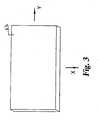
Fig. 3 , there is set forth a purely illustrative plan view of a portion of alayer 53.Layer 53 represents a portion of a layer formed in astereolithography apparatus 500 that utilized a wiper blade moved in the direction of axis Y to level the photo-polymerizable ceramic filled resin prior to receiving a dose of energy. The wiper blade interacts with the photo-polymerizable ceramic filled material and affects the homogeneity in at least two dimensions. The inventors have discovered that the shrinkage in the item associated with a subsequent sintering act is anisotropic in the three directions; for example the X, Y and Z directions. Anisotropic shrinkage can be considered to occur when isotropic shrinkage is not sufficient to keep the sintered item within a predetermined geometric tolerance. In the discussion of the anisotropic shrinkage relative to the X, Y and Z axis the Z axis represents the build direction and the Y axis represents the direction of the movement of the wiper blade. The inventors have determined that shrinkage in the Z direction (build direction) is greater than in the X and Y directions. Factors to consider when evaluating the shrinkage are the solid loading in the photo-polymerizable resin, the resin formulation, the build style and orientation and how the item is sintered. - With reference to
Fig. 4 , there is illustrated one embodiment of a shrinkage measurement test model 300. In one form the shrinkage measurement test model 300 is created as a solid body model and then generated as an STL file. In one form the item is oriented such that the back corner represents the origin of a Cartesian coordinate system X, Y, Z. The vertical direction of the STL being aligned with the Z axis and the twosides 301 and 302 being aligned with the X and Y axis respectively. The item is than built in a stereolithography apparatus with the Cartesian coordinate system of the item aligned with the coordinate system of the stereolithography apparatus. The present invention can be utilized with any suitable file format and/or hardware. - The shrinkage measurement test model 300 in the green state is then subjected to a comprehensive inspection to quantify dimensions of the item. The measurements taken during inspection can be obtained with known equipment such as, but not limited to calipers and/or coordinate measuring machines. In one form the shrinkage measurement test model has been designed so that all of the inspection dimensions line up along the X, Y and/or Z axis. The item is then subjected to a firing act to burn off the photo-polymer and sinter the ceramic material. The comprehensive inspection is repeated to quantify the dimensions of the item after being sintered.
- The measured values from the comprehensive inspection after firing are than compared with the inspection values from the green state item. In one form the comparison is done by plotting the measured values of the fired item against the measured values from the green state item. A least squares analysis is performed to obtain a linear equation. The resulting slope of the equations is the shrinkage factors for each of the X, Y and Z direction/dimensions. The shrinkage for each of the X, Y and Z directions/dimensions are applied to one of the STL file or the solid body model to expand the dimensions in the respective directions of the coordinate system. The process will modify one of the STL file or the solid body model in the directions of the coordinate system to account for the anisotropic shrinkage of the item. In one non-limiting example the shrinkage factors to account for shrinkage are 118%, 115% and 120 % in the X, Y, Z direction respectively for an item having a length of about 5.1cm (two inches). The present application contemplates a wide variety of shrinkage factors and is not limited in any manner to these factors unless specifically provided o the contrary.
- The application of the present invention enables the production of sintered ceramic items having substantially conformity with the item's design parameters. In one form the dimensional accuracy of the sintered ceramic item to the design parameters is within a range of 0.0% to 1.5% and in another form the dimensional accuracy is within a range of 0.0% to 0.5%. Further, the present invention is also applicable to form sintered ceramic items in either near net shape or net shape. Additionally, other degrees of dimensional accuracy are contemplated herein.
- In an alternate form the comparison utilized to calculate the shrinkage factors of the shrinkage measurement test model is between the inspection values of the fired test model and the dimensional design values from the solid body model. The process as described above is then continued to find the shrinkage factors for the X, Y and Z dimensions/directions.
- With reference to
Fig. 5 , there is illustrated one non-limiting embodiment of a system for creating abuild file 1005 that determines how the item 45 is created in the stereolithography apparatus. This process is representative of a technique that can be utilized to produce the build file, but the present application is not intended to be limited to the one embodiment inFig. 5 unless specifically stated to the contrary. Inact 1000 data defining parameters of the item are collected and processed to define a specification for the item design. The data fromact 1000 is utilized inact 1001 to construct an item model using, for example, a computer modeling system. In one embodiment the computer modeling system creates an electronic model such as but not limited to a solid body model. However, other modeling systems are contemplated herein. The item model fromact 1001 is then processed in a modifieditem model act 1002 to create a model of the item taking into account the anisotropic shrinkage. While the present application discusses the process in terms of modification of the item model it is understood that the same type of modification is applicable to the STUSTC files to create a modified item file. The modifieditem act 1002 utilizes an X shrinkage factor, a Y shrinkage factor and a Z shrinkage factor. The shrinkage factors are used to increase the respective underlaying dimensions to a modified dimension. The X, Y and Z shrinkage factors will be applied so that they correspond to the coordinate system of the stereolithography apparatus. - In one form a
conversion act 1003 is utilized to convert the modified item model, produced inact 1002 to a file format, such as STL or SLC. Next, the file fromact 1003 is processed inact 1004 to create discrete two-dimensional slices appropriate for drawing the layers of the item and any required supports. Inact 1005 the build file is completed, which will be utilized to drive the energy source of the stereolithography apparatus and produce the green ceramic item. - In one form the ceramic filled resin comprises a sinterable ceramic material, a photocurable monomer, a photoinitiator and a dispersant. The ceramic filled resin is adapted for use in stereolithography to produce a green ceramic item. In one form the filled resin is prepared by admixing the components to provide a filled resin having viscosity within a range of about 300 centipoise to about 3,500 centipoise at a shear rate of about .4 per second; in another form the filled resin has a viscosity of about 2,500 centipoise at a shear rate of about .4 per second. However, the present application contemplates filled resins having other viscosity values.
- The loading of ceramic material within the resin is contemplated within a range of 35% to 65% by volume. Another form of the ceramic loading within the resin is contemplated as being about 50.3 % by volume. In one preferred resin the ceramic loading has the volume percent of ceramic material substantially equal to the weight percent of ceramic material within the resin. However, resins having other ceramic loadings are fully contemplated herein. More specifically, the present application contemplates that the volume percent of the ceramic material in the resin may be equal to the weight percent of the ceramic material in the resin or that the volume percent of the ceramic material in the resin may be unequal to the weight percent of the ceramic material in the resin. The sinterable ceramic material can be selected from a wide variety of ceramic materials. Specific examples include, but are not limited to, alumina, yttria, magnesia, silicon nitride, silica and mixtures thereof.
- In one example alumina is selected as the sinterable ceramic material. Alumina can be provided as a dry powder having an average particle size suitable for sintering to provide an item having the desired characteristics. In one form the powdered alumina has an average particle size within a range of 0.1 microns to 5.0 microns. In another form the powdered alumina is selected to have an average particle size within a range of 0.5 microns to 1.0 microns. However, other particle sizes for the alumina material are contemplated herein.
- The monomer is selected from any suitable monomer that can be induced to polymerize when irradiated in the presence of a photoinitiator. Examples of monomers include acrylate esters and substituted acrylate esters. A combination of two or more monomers may be used. Preferably at least one of the monomers is a multifunctional monomer. By multifunctional monomer it is understood that the monomer includes more than two functional moieties capable of forming bonds with a growing polymer chain. Specific examples of monomers that can be used with this invention include 1,6-hexanediol diacrylate (HDDA) and 2-phenoxyethyl acrylate (POEA). In one form the photocurable monomers are present in an amount between about 10 wt % to about 40 wt %, and in another form about 10 wt % to about 35 wt % , and in yet another form about 20 wt % to 35 wt % based upon the total weight of the filled resin. However, the present application contemplates other amounts of monomers.
- The dispersant is provided in an amount suitable to maintain a substantially uniform colloidal suspension of the alumina in the filled resin. The dispersant can be selected from a wide variety of known surfactants. Dispersants contemplated herein include, but are not limited to, ammonium salts, more preferably tetraalkyl ammonium salts. Examples of dispersants for use in this invention include, but are not limited to: polyoxypropylene diethyl-2-hydroxyethyl ammonium acetate, and ammonium chloride. In one form the amount of dispersant is between about 1.0 wt % and about 10 wt % based upon the total weight of the ceramic within the filled resin. However, the present application contemplates other amounts of dispersants.
- The initiator is selected from a number of commercially available photoinitiators believed known to those skilled in the art. The photoinitiator is selected to be suitable to induce polymerization of the desired monomer when irradiated. Typically the selection of a photoinitiator will be dictated by the wavelength of radiation used to induce polymerization. Photoinitiators contemplated herein include, but are not limited to benzophenone, trimethyl benzophenone, 1-hydroxycyclohexyl phenyl ketone, isopropylthioxanthone, 2-methyl-1-[4 (methylthio)phenyl]-2-morpholinoprophanone and mixtures thereof. The photoinitiator is added in an amount sufficient to polymerize the monomers when the filled resin is irradiated with radiation of appropriate wavelength. In one form the amount of photoinitiator is between about 0.05 wt % and about 5 wt % based upon the total weight of the monomer within the filled resin. However, other amounts of photoiniators are contemplated herein.
- In an alternate form of the ceramic filled resin a quantity of a nonreactive diluent is substituted for a quantity of the monomer. In one form the amount of substituted nonreactive diluent is equal to between about 5% and about 20% (by weight) of the monomer in the resin. However, the present application contemplates that other amounts of non-reactive diluents are considered herein. An illustration of a given ceramic resin composition requires 100 grams of a monomer that in the alternate form will replace about 5 -20 wt % of the monomer with a nonreactive diluent (i.e. 95 - 80 grams of monomer + 5-20 grams of nonreactive diluent). The nonreactive diluent includes but is not limited to a dibasic ester or a decahydronaphthalene. Examples of dibasic esters include dimethyl succinate, dimethyl glutarate, and dimethyl adipate, which are available in a pure form or a mixture.
- The filled resin is prepared by combining the monomer, the dispersant and the sinterable ceramic to form a homogeneous mixture. Although the order of addition is not critical to this invention typically, the monomer and the dispersant are combined first and then the sinterable ceramic is added. In one form the sinterable ceramic material is added to the monomer/dispersant combination in increments of about 5 to about 20 vol. %. Between each incremental addition of the ceramic material, the resulting mixture is thoroughly mixed by any suitable method, for example, ball milling for about 5 to about 120 minutes. When all of the sinterable ceramic material has been added, the resulting mixture is mixed for an additional amount of time up to 10 hours or more. The photoinitiator is added and blended into the mixture.
- With reference to Table I there is set forth one example of an alumina filled resin. However, the present application is not intended to be limited to the specific composition set forth below unless specifically stated to the contrary.
wt/g vol cc wt% vol % Alumina 1980 500 78.2 48.0 Monomer 510 500 20.1 48.0 Dispersant 39.6 38.8 1.56 3.73 Photoinitiator 2.55 2.32 0.101 0.223 Total 2532 1041 100% 100% - In one form the green ceramic item is sintered to a temperature within a ra nge of 1100 °C to 1700 ºC. The present invention contemplates other sintering parameters. Further, the present invention contemplates sintering to a variety of theoretical densities, including but not limited to about 60% of theoretical density. The density of the sintered material is preferably greater than sixty percent of the theoretical density, and densities equal to or greater than about ninety-four percent of the theoretical density are more preferred. However, the present invention contemplates other densities.
- The present application contemplates the utilization of a three dimensional coordinate system as a reference for an item being fabricated from the photo-polymerizable ceramic filled resin. As discussed above the inventors have discovered that the shrinkage of the item in a subsequent sintering act is anisotropic in the three directions. Therefore, in the present invention there are utilized three unequal scaling factors to take into consideration the respective shrinkage in the dimensions of the item in all three directions.
- While the inventions have been illustrated and described in detail in the drawings and foregoing description, the same is to be considered as illustrative and not restrictive in character, it being understood that only the preferred embodiment has been shown and described. It should be understood that while the use of the word preferable, preferably or preferred in the description above indicates that the feature so described may be more desirable, it nonetheless may not be necessary and embodiments lacking the same may be contemplated as within the scope of the invention, that scope being defined by the claims that follow. In reading the claims it is intended that when words such as "a," "an," "at least one," "at least a portion" are used there is no intention to limit the claim to only one item unless specifically stated to the contrary in the claim. Further, when the language "at least a portion" and/or "a portion" is used the item may include a portion and/or the entire item unless specifically stated to the contrary.
Claims (16)
- A method, comprising:representing an item including its dimensions relative to a three dimensional coordinate system, the item adapted to be formed as a green ceramic item in a stereolithography apparatus from a photo-polymerizable material including ceramic particles;applying three unequal scaling factors to the dimensions to compensate for the anisotropic shrinkage of the green ceramic item relative to the axes of the coordinate system upon the green ceramic item being sintered;building the green ceramic item in the stereolithography apparatus after said applying; andheating the green ceramic item to form a sintered ceramic item substantially conforming to the dimensions.
- The method of claim 1, further comprising applying a largest scaling value to one of the unequal scaling factors corresponding to a build direction.
- The method of claim 1, wherein said building includes forming a plurality of layers of the photo-polymerizable material; and
which further includes leveling at least one of the plurality of layers of the photo-polymerizable material prior to forming the next of the plurality of layers of the photo-polymerizable material; and
which further includes exposing the at least one of the plurality of layers of the photo-polymerizable material with a dose of energy prior to forming the next of the plurality of layers of the photo-polymerizable material. - The method of claim 3, wherein said leveling including mechanically wiping a surface of the at least one of the plurality of layers of the photo-polymerizable material.
- The method of claim 4, wherein said mechanically wiping changes the homogeneity of the ceramic particles in at least two dimensions.
- The method of claim 4, wherein said leveling includes leveling each of the plurality of layers of the photo-polymerizable material; and
which further includes exposing each of the plurality of layers of the photo-polymerizable material with a dose of energy. - The method of claim 1, wherein the stereolothography apparatus includes a machine three dimensional coordinate system coextensive with the three dimensional coordinate system.
- The method of claim 1, wherein the sintered ceramic item is of a near net shape.
- The method of claim 1, wherein the sintered ceramic item is of a net shape.
- The method of claim 1, wherein the sintered ceramic item is dimensionally accurate with the dimensions within about 1.5%.
- The method of claim 1, wherein the sintered ceramic item is dimensionally accurate with the dimensions within about 0.5%.
- The method of claim 1, wherein said heating includes burning off a polymer in the green ceramic item.
- The method of claim 2, wherein the three dimensional coordinate system is a Cartesian coordinate system including a first axis corresponding to the X axis and a second axis corresponding to the Y axis and a third axis corresponding to the Z axis;
wherein the stereolothography apparatus includes a machine three dimensional coordinate system coextensive with the three dimensional coordinate system;
which further includes the Z axis corresponding to the build direction;
wherein said building includes forming a plurality of layers from the photo-polymerizable material in the build direction; and
which further includes wiping an upper surface of each of the plurality of layers of the photo-polymerizable material prior to being exposed to an energy dose, said wiping in the direction of one of the other axes. - The method of claim 1, wherein the photo-polymerizable material includes ceramic particles within a range of 35% to 65% by volume.
- The method of claim 1, wherein said representing is associated with any of electronic data, digital data, virtual data, computer files, solid body modeling, computer modeling, computer aided manufacturing.
- The method of claim 1, wherein said heating is to a temperature within a range of about 1100 °C to 1700 °C.
Priority Applications (1)
| Application Number | Priority Date | Filing Date | Title |
|---|---|---|---|
| EP11005327.9AEP2402127B1 (en) | 2004-10-19 | 2005-10-18 | Method associated with anisotropic shrink in sintered ceramic items |
Applications Claiming Priority (2)
| Application Number | Priority Date | Filing Date | Title |
|---|---|---|---|
| US62010404P | 2004-10-19 | 2004-10-19 | |
| PCT/US2005/037681WO2006045002A2 (en) | 2004-10-19 | 2005-10-18 | Method and apparatus associated with anisotropic shrink in sintered ceramic items |
Related Child Applications (3)
| Application Number | Title | Priority Date | Filing Date |
|---|---|---|---|
| EP11005327.9ADivisionEP2402127B1 (en) | 2004-10-19 | 2005-10-18 | Method associated with anisotropic shrink in sintered ceramic items |
| EP11005327.9ADivision-IntoEP2402127B1 (en) | 2004-10-19 | 2005-10-18 | Method associated with anisotropic shrink in sintered ceramic items |
| EP13173393Division-Into | 2013-06-24 |
Publications (3)
| Publication Number | Publication Date |
|---|---|
| EP1810206A2 EP1810206A2 (en) | 2007-07-25 |
| EP1810206A4 EP1810206A4 (en) | 2009-04-08 |
| EP1810206B1true EP1810206B1 (en) | 2014-07-09 |
Family
ID=36203691
Family Applications (2)
| Application Number | Title | Priority Date | Filing Date |
|---|---|---|---|
| EP11005327.9AExpired - LifetimeEP2402127B1 (en) | 2004-10-19 | 2005-10-18 | Method associated with anisotropic shrink in sintered ceramic items |
| EP05816262.9AExpired - LifetimeEP1810206B1 (en) | 2004-10-19 | 2005-10-18 | Method associated with anisotropic shrink in sintered ceramic items |
Family Applications Before (1)
| Application Number | Title | Priority Date | Filing Date |
|---|---|---|---|
| EP11005327.9AExpired - LifetimeEP2402127B1 (en) | 2004-10-19 | 2005-10-18 | Method associated with anisotropic shrink in sintered ceramic items |
Country Status (5)
| Country | Link |
|---|---|
| US (4) | US7551977B2 (en) |
| EP (2) | EP2402127B1 (en) |
| JP (2) | JP2008516820A (en) |
| CA (1) | CA2584104C (en) |
| WO (1) | WO2006045002A2 (en) |
Families Citing this family (52)
| Publication number | Priority date | Publication date | Assignee | Title |
|---|---|---|---|---|
| US8784723B2 (en) | 2007-04-01 | 2014-07-22 | Stratasys Ltd. | Method and system for three-dimensional fabrication |
| KR20090032543A (en)* | 2007-09-28 | 2009-04-01 | 한국과학기술원 | How to make 3D large sculptures |
| EP2279499B1 (en)* | 2008-04-14 | 2016-11-23 | Rolls-Royce Corporation | Method for producing ceramic stereolithography parts |
| US20100028645A1 (en) | 2008-08-04 | 2010-02-04 | Michael Maguire | Adaptive supports for green state articles and methods of processing thereof |
| US20100052197A1 (en)* | 2008-08-27 | 2010-03-04 | Thomas James Deneka | Method for Manufacturing Ceramic Honeycombs |
| GB0816258D0 (en)* | 2008-09-05 | 2008-10-15 | Ulive Entpr Ltd | Process |
| US20100140852A1 (en) | 2008-12-04 | 2010-06-10 | Objet Geometries Ltd. | Preparation of building material for solid freeform fabrication |
| US8794298B2 (en) | 2009-12-30 | 2014-08-05 | Rolls-Royce Corporation | Systems and methods for filtering molten metal |
| DE102011085154A1 (en)* | 2011-10-25 | 2013-04-25 | Evonik Industries Ag | Device for preventing deposits on optical components in laser sintering |
| CN105122135B (en) | 2013-02-12 | 2020-03-20 | 卡本有限公司 | Continuous liquid mesophase printing |
| US9498920B2 (en) | 2013-02-12 | 2016-11-22 | Carbon3D, Inc. | Method and apparatus for three-dimensional fabrication |
| US11260208B2 (en) | 2018-06-08 | 2022-03-01 | Acclarent, Inc. | Dilation catheter with removable bulb tip |
| US12151073B2 (en) | 2013-08-14 | 2024-11-26 | Carbon, Inc. | Continuous liquid interphase printing |
| US9360757B2 (en) | 2013-08-14 | 2016-06-07 | Carbon3D, Inc. | Continuous liquid interphase printing |
| WO2015080888A2 (en)* | 2013-11-26 | 2015-06-04 | Eipi Systems, Inc. | Rapid 3d continuous printing of casting molds for metals and other materials |
| EP3094471B1 (en)* | 2014-01-16 | 2021-06-02 | Hewlett-Packard Development Company, L.P. | Processing three-dimensional object data of an object to be generated by an additive manufacturing process |
| US10471699B2 (en) | 2014-06-20 | 2019-11-12 | Carbon, Inc. | Three-dimensional printing with reciprocal feeding of polymerizable liquid |
| AU2015280230B2 (en) | 2014-06-23 | 2019-05-16 | Carbon, Inc. | Polyurethane resins having multiple mechanisms of hardening for use in producing three-dimensional objects |
| WO2016126796A2 (en) | 2015-02-05 | 2016-08-11 | Carbon3D, Inc. | Method of additive manufacturing by intermittent exposure |
| JP6458543B2 (en)* | 2015-02-23 | 2019-01-30 | 株式会社リコー | Modeling data creation device, program, modeling device |
| EP3061546A1 (en)* | 2015-02-25 | 2016-08-31 | General Electric Technology GmbH | Method for manufacturing a part by means of an additive manufacturing technique |
| WO2016140886A1 (en) | 2015-03-05 | 2016-09-09 | Carbon3D, Inc. | Fabrication of three dimensional objects with multiple operating modes |
| EP3344676B1 (en) | 2015-09-04 | 2023-04-12 | Carbon, Inc. | Cyanate ester dual cure resins for additive manufacturing |
| CN108291011B (en) | 2015-09-09 | 2021-03-02 | 卡本有限公司 | Epoxy dual cure resin for additive manufacturing |
| US10647873B2 (en) | 2015-10-30 | 2020-05-12 | Carbon, Inc. | Dual cure article of manufacture with portions of differing solubility |
| US11891485B2 (en) | 2015-11-05 | 2024-02-06 | Carbon, Inc. | Silicone dual cure resins for additive manufacturing |
| WO2017112751A1 (en) | 2015-12-22 | 2017-06-29 | Carbon, Inc. | Blocked silicone dual cure resins for additive manufacturing |
| US10343331B2 (en) | 2015-12-22 | 2019-07-09 | Carbon, Inc. | Wash liquids for use in additive manufacturing with dual cure resins |
| JP6944935B2 (en) | 2015-12-22 | 2021-10-06 | カーボン,インコーポレイテッド | Manufacture of composite products from multiple intermediates by laminated molding using double-cured resin |
| US10647054B2 (en) | 2015-12-22 | 2020-05-12 | Carbon, Inc. | Accelerants for additive manufacturing with dual cure resins |
| WO2017112571A1 (en)* | 2015-12-22 | 2017-06-29 | Carbon, Inc. | Dual cure additive manufacturing of rigid intermediates that generate semi-rigid, flexible, or elastic final products |
| CN115195104B (en) | 2015-12-22 | 2023-12-05 | 卡本有限公司 | Dual precursor resin system for additive manufacturing with dual cure resins |
| US10501572B2 (en) | 2015-12-22 | 2019-12-10 | Carbon, Inc. | Cyclic ester dual cure resins for additive manufacturing |
| US11072088B2 (en) | 2016-01-29 | 2021-07-27 | Hewlett-Packard Development Company, L.P. | Three-dimensional printer |
| US10493523B1 (en) | 2016-02-04 | 2019-12-03 | Williams International Co., L.L.C. | Method of producing a cast component |
| KR101859642B1 (en)* | 2016-04-26 | 2018-05-18 | 고려대학교 산학협력단 | System for manufacturing three-dimensional porous scaffolds using photocurable slurry and method for manufacturing photocurable slurry |
| KR20170122101A (en)* | 2016-04-26 | 2017-11-03 | 고려대학교 산학협력단 | System and method for manufacturing three-dimensional porous scaffolds |
| US10500786B2 (en) | 2016-06-22 | 2019-12-10 | Carbon, Inc. | Dual cure resins containing microwave absorbing materials and methods of using the same |
| US20180009128A1 (en)* | 2016-07-08 | 2018-01-11 | Renaissance Services, Inc. | Generation of casting molds by additive manufacturing |
| WO2018094131A1 (en) | 2016-11-21 | 2018-05-24 | Carbon, Inc. | Method of making three-dimensional object by delivering reactive component for subsequent cure |
| WO2018119067A1 (en)* | 2016-12-20 | 2018-06-28 | Basf Se | Photopolymer ceramic dispersion |
| US11535686B2 (en) | 2017-03-09 | 2022-12-27 | Carbon, Inc. | Tough, high temperature polymers produced by stereolithography |
| CN110446609A (en) | 2017-04-21 | 2019-11-12 | 惠普发展公司,有限责任合伙企业 | Compensate the contraction of object in 3D printing |
| US10316213B1 (en) | 2017-05-01 | 2019-06-11 | Formlabs, Inc. | Dual-cure resins and related methods |
| IT201700050248A1 (en)* | 2017-05-09 | 2018-11-09 | Graf Synergy Srl | PROCEDURE FOR THREE-DIMENSIONAL PRINTING, PARTICULARLY FOR THE IMPLEMENTATION OF WINDOWS, ELASTIC ELEMENTS FOR FLOORS OR SIMILAR |
| JP6894015B2 (en) | 2017-06-21 | 2021-06-23 | カーボン,インコーポレイテッド | Laminated modeling method |
| US10538460B2 (en)* | 2018-03-15 | 2020-01-21 | General Electric Company | Ceramic slurries for additive manufacturing techniques |
| US11504903B2 (en) | 2018-08-28 | 2022-11-22 | Carbon, Inc. | 1K alcohol dual cure resins for additive manufacturing |
| US11794412B2 (en) | 2019-02-20 | 2023-10-24 | General Electric Company | Method and apparatus for layer thickness control in additive manufacturing |
| WO2021046615A1 (en)* | 2019-09-12 | 2021-03-18 | The University Of Sydney | Compositions and method of printing ceramic materials |
| CN112776341B (en)* | 2020-12-15 | 2022-07-08 | 同济大学 | Shaft action optimization method of six-shaft robot in three-dimensional printing equipment |
| KR102844266B1 (en)* | 2022-08-02 | 2025-08-11 | 주식회사 엠오피(M.O.P Co., Ltd.) | High precision photocurable 3D printing method and high precision sculpture manufacturing method using the same |
Family Cites Families (39)
| Publication number | Priority date | Publication date | Assignee | Title |
|---|---|---|---|---|
| US5554336A (en) | 1984-08-08 | 1996-09-10 | 3D Systems, Inc. | Method and apparatus for production of three-dimensional objects by stereolithography |
| JPS61192520A (en)* | 1985-02-20 | 1986-08-27 | 斉藤 長男 | Manufacture of powder sintering product |
| ATE138293T1 (en) | 1986-10-17 | 1996-06-15 | Univ Texas | METHOD AND DEVICE FOR PRODUCING SINTERED MOLDED BODIES BY PARTIAL INTERNATION |
| US5017753A (en) | 1986-10-17 | 1991-05-21 | Board Of Regents, The University Of Texas System | Method and apparatus for producing parts by selective sintering |
| US5256340A (en) | 1988-04-18 | 1993-10-26 | 3D Systems, Inc. | Method of making a three-dimensional object by stereolithography |
| US5258146A (en) | 1988-09-26 | 1993-11-02 | 3D Systems, Inc. | Method of and apparatus for measuring and controlling fluid level in stereolithography |
| US5430666A (en) | 1992-12-18 | 1995-07-04 | Dtm Corporation | Automated method and apparatus for calibration of laser scanning in a selective laser sintering apparatus |
| JP3173212B2 (en)* | 1993-03-19 | 2001-06-04 | ソニー株式会社 | Optical shaping method and optical shaping apparatus |
| JPH06329460A (en)* | 1993-05-24 | 1994-11-29 | Toshiba Ceramics Co Ltd | Method for optical forming of ceramic |
| US5552995A (en)* | 1993-11-24 | 1996-09-03 | The Trustees Of The Stevens Institute Of Technology | Concurrent engineering design tool and method |
| JPH0812442A (en)* | 1994-06-22 | 1996-01-16 | Toshiba Ceramics Co Ltd | Slurry for ceramic composite material and method for molding the same |
| US5733497A (en) | 1995-03-31 | 1998-03-31 | Dtm Corporation | Selective laser sintering with composite plastic material |
| JPH0985839A (en)* | 1995-09-27 | 1997-03-31 | Olympus Optical Co Ltd | Preparation of sintered structural body |
| US6270335B2 (en)* | 1995-09-27 | 2001-08-07 | 3D Systems, Inc. | Selective deposition modeling method and apparatus for forming three-dimensional objects and supports |
| DE69700945T2 (en) | 1996-04-17 | 2000-07-20 | Koninklijke Philips Electronics N.V., Eindhoven | METHOD FOR PRODUCING A SINTERED STRUCTURE ON A SUBSTRATE |
| US5951304A (en)* | 1997-05-21 | 1999-09-14 | General Electric Company | Fanout interconnection pad arrays |
| US5849238A (en) | 1997-06-26 | 1998-12-15 | Ut Automotive Dearborn, Inc. | Helical conformal channels for solid freeform fabrication and tooling applications |
| DE19747309B4 (en) | 1997-10-27 | 2007-11-15 | Degussa Gmbh | Use of a polyamide 12 for selective laser sintering |
| US6027326A (en) | 1997-10-28 | 2000-02-22 | Sandia Corporation | Freeforming objects with low-binder slurry |
| JPH11171651A (en)* | 1997-12-09 | 1999-06-29 | Toto Ltd | Production of ceramic compact |
| US5989476A (en) | 1998-06-12 | 1999-11-23 | 3D Systems, Inc. | Process of making a molded refractory article |
| US6932145B2 (en)* | 1998-11-20 | 2005-08-23 | Rolls-Royce Corporation | Method and apparatus for production of a cast component |
| US6399010B1 (en) | 1999-02-08 | 2002-06-04 | 3D Systems, Inc. | Method and apparatus for stereolithographically forming three dimensional objects with reduced distortion |
| US6656409B1 (en) | 1999-07-07 | 2003-12-02 | Optomec Design Company | Manufacturable geometries for thermal management of complex three-dimensional shapes |
| US6517773B1 (en) | 1999-09-23 | 2003-02-11 | Innovative Technology Licensing, Llc | Direct metal fabrication of parts with surface features only |
| IL135936A (en)* | 2000-05-02 | 2004-06-20 | Cohen Michael | Alumina ceramic products |
| US6782940B2 (en)* | 2000-06-07 | 2004-08-31 | Romain L. Billiet | Method for rapid reproduction of molds and mold components |
| DE10065960C5 (en) | 2000-06-07 | 2005-10-06 | (bu:st) GmbH Beratungsunternehmen für Systeme und Technologien | Method for producing a workpiece with exact geometry |
| US7108801B2 (en) | 2001-01-23 | 2006-09-19 | Southwest Reasearch Institute | Methods and blends for controlling rheology and transition temperature of liquid crystals |
| US6896839B2 (en) | 2001-02-07 | 2005-05-24 | Minolta Co., Ltd. | Three-dimensional molding apparatus and three-dimensional molding method |
| DE10108612C1 (en) | 2001-02-22 | 2002-06-27 | Daimler Chrysler Ag | Selective laser sintering of a powder used as a rapid prototyping process comprises adding the powder to an encapsulated chamber, and forming a powder cake |
| US7087200B2 (en) | 2001-06-22 | 2006-08-08 | The Regents Of The University Of Michigan | Controlled local/global and micro/macro-porous 3D plastic, polymer and ceramic/cement composite scaffold fabrication and applications thereof |
| US7381283B2 (en)* | 2002-03-07 | 2008-06-03 | Yageo Corporation | Method for reducing shrinkage during sintering low-temperature-cofired ceramics |
| JP2004136647A (en)* | 2002-06-06 | 2004-05-13 | Ngk Insulators Ltd | Manufacturing method of composite sintered body, manufacturing method of composite molded body, and composite sintered body and composite molded body |
| JP2004017295A (en)* | 2002-06-12 | 2004-01-22 | Matsushita Electric Ind Co Ltd | Manufacturing method of ceramic green sheet |
| JP2004042546A (en)* | 2002-07-15 | 2004-02-12 | Inst Of Physical & Chemical Res | Additive manufacturing method for functional materials |
| DE60333019D1 (en) | 2002-07-23 | 2010-07-29 | Univ Southern California | MANUFACTURE OF METAL PARTS USING SIS SINTERING (SIS - SELECTIVE INHIBITION OF SINTERING) |
| US20040021256A1 (en) | 2002-07-25 | 2004-02-05 | Degrange Jeffrey E. | Direct manufacture of aerospace parts |
| JP2004203643A (en)* | 2002-12-24 | 2004-07-22 | Kyocera Corp | Manufacturing method of ceramic green sheet |
- 2005
- 2005-10-18EPEP11005327.9Apatent/EP2402127B1/ennot_activeExpired - Lifetime
- 2005-10-18WOPCT/US2005/037681patent/WO2006045002A2/enactiveApplication Filing
- 2005-10-18EPEP05816262.9Apatent/EP1810206B1/ennot_activeExpired - Lifetime
- 2005-10-18JPJP2007538019Apatent/JP2008516820A/ennot_activeWithdrawn
- 2005-10-18CACA2584104Apatent/CA2584104C/ennot_activeExpired - Fee Related
- 2007
- 2007-04-19USUS11/788,286patent/US7551977B2/ennot_activeExpired - Fee Related
- 2009
- 2009-06-22USUS12/456,766patent/US20100114357A1/ennot_activeAbandoned
- 2011
- 2011-09-26USUS13/245,442patent/US20120015797A1/ennot_activeAbandoned
- 2012
- 2012-10-01JPJP2012219549Apatent/JP5795756B2/ennot_activeExpired - Fee Related
- 2012-10-02USUS13/633,565patent/US20140284848A9/ennot_activeAbandoned
Also Published As
| Publication number | Publication date |
|---|---|
| EP1810206A4 (en) | 2009-04-08 |
| US7551977B2 (en) | 2009-06-23 |
| WO2006045002A3 (en) | 2007-04-12 |
| JP2008516820A (en) | 2008-05-22 |
| EP2402127A2 (en) | 2012-01-04 |
| JP5795756B2 (en) | 2015-10-14 |
| US20100114357A1 (en) | 2010-05-06 |
| CA2584104C (en) | 2012-12-11 |
| US20140284848A9 (en) | 2014-09-25 |
| EP1810206A2 (en) | 2007-07-25 |
| EP2402127B1 (en) | 2018-07-18 |
| CA2584104A1 (en) | 2006-04-27 |
| JP2013056548A (en) | 2013-03-28 |
| WO2006045002A2 (en) | 2006-04-27 |
| US20120015797A1 (en) | 2012-01-19 |
| US20130154161A1 (en) | 2013-06-20 |
| US20080063867A1 (en) | 2008-03-13 |
| EP2402127A3 (en) | 2012-06-06 |
Similar Documents
| Publication | Publication Date | Title |
|---|---|---|
| EP1810206B1 (en) | Method associated with anisotropic shrink in sintered ceramic items | |
| Hu et al. | Design of a shaping system for stereolithography with high solid loading ceramic suspensions | |
| Schwarzer et al. | Process development for additive manufacturing of functionally graded alumina toughened zirconia components intended for medical implant application | |
| Wang et al. | Fabrication of zirconia ceramic parts by using solvent-based slurry stereolithography and sintering | |
| Revilla-León et al. | Additive manufacturing technologies for processing zirconia in dental applications | |
| Kovacev et al. | Effect of the preparation techniques of photopolymerizable ceramic slurry and printing parameters on the accuracy of 3D printed lattice structures | |
| JP7547050B2 (en) | Method and apparatus for forming, particularly applicable to metals and/or ceramics | |
| Wang et al. | Additive manufacturing of silica ceramics from aqueous acrylamide based suspension | |
| CN113316460A (en) | Paste for photocuring 3D printing, preparation method and use method thereof | |
| Utela et al. | Development process for custom three-dimensional printing (3DP) material systems | |
| JP2008516820A5 (en) | ||
| CN107353036A (en) | A kind of porous silicon nitride ceramic based on increases material manufacturing technology, its preparation method and its application | |
| Tian et al. | Preliminary research on mechanical properties of 3D printed rock structures | |
| Huang et al. | Reinforcement effect in printing precision and sintering performance for liquid crystal display stereolithography additive manufacturing of alumina ceramics | |
| JP7323361B2 (en) | Layered manufacturing powder, layered manufacturing slurry, three-dimensional layered manufacturing body, sintered body, manufacturing method of layered manufacturing slurry, layered manufacturing method, and sintering method | |
| Wang et al. | Photopolymerization-based three-dimensional ceramic printing technology | |
| CN114378918B (en) | Additive manufacturing apparatus for ceramic and additive manufacturing method for ceramic | |
| Fu et al. | Silicon carbide ceramics manufactured by digital light processing and low temperature sintering | |
| Brady et al. | Solid freeform fabrication of ceramics by stereolithography | |
| Saqib et al. | Systematic optimization of silicon nitride slurries for high-precision photopolymerization 3D printing | |
| US20210069969A1 (en) | Method of 3d printing metal part | |
| Wu | Parametric study and optimization of ceramic stereolithography | |
| Chen | Advances in ceramic 3D printing technologies and optimization research | |
| Sarwar et al. | Optimized Zirconia 3D Printing Using Digital Light Processing with Continuous Film Supply and Recyclable Slurry System. Materials 2021, 14, 3446 | |
| JP2021142739A (en) | Method for producing ceramic molded body, and ceramic molded body |
Legal Events
| Date | Code | Title | Description |
|---|---|---|---|
| PUAI | Public reference made under article 153(3) epc to a published international application that has entered the european phase | Free format text:ORIGINAL CODE: 0009012 | |
| 17P | Request for examination filed | Effective date:20070426 | |
| AK | Designated contracting states | Kind code of ref document:A2 Designated state(s):AT BE BG CH CY CZ DE DK EE ES FI FR GB GR HU IE IS IT LI LT LU LV MC NL PL PT RO SE SI SK TR | |
| AX | Request for extension of the european patent | Extension state:AL BA HR MK YU | |
| DAX | Request for extension of the european patent (deleted) | ||
| A4 | Supplementary search report drawn up and despatched | Effective date:20090310 | |
| 17Q | First examination report despatched | Effective date:20090619 | |
| DAC | Divisional application: reference to earlier application (deleted) | ||
| GRAP | Despatch of communication of intention to grant a patent | Free format text:ORIGINAL CODE: EPIDOSNIGR1 | |
| INTG | Intention to grant announced | Effective date:20140127 | |
| GRAS | Grant fee paid | Free format text:ORIGINAL CODE: EPIDOSNIGR3 | |
| GRAA | (expected) grant | Free format text:ORIGINAL CODE: 0009210 | |
| AK | Designated contracting states | Kind code of ref document:B1 Designated state(s):AT BE BG CH CY CZ DE DK EE ES FI FR GB GR HU IE IS IT LI LT LU LV MC NL PL PT RO SE SI SK TR | |
| REG | Reference to a national code | Ref country code:GB Ref legal event code:FG4D | |
| REG | Reference to a national code | Ref country code:AT Ref legal event code:REF Ref document number:676801 Country of ref document:AT Kind code of ref document:T Effective date:20140715 Ref country code:CH Ref legal event code:EP | |
| REG | Reference to a national code | Ref country code:IE Ref legal event code:FG4D | |
| REG | Reference to a national code | Ref country code:DE Ref legal event code:R096 Ref document number:602005044155 Country of ref document:DE Effective date:20140821 | |
| REG | Reference to a national code | Ref country code:AT Ref legal event code:MK05 Ref document number:676801 Country of ref document:AT Kind code of ref document:T Effective date:20140709 | |
| REG | Reference to a national code | Ref country code:NL Ref legal event code:VDEP Effective date:20140709 | |
| REG | Reference to a national code | Ref country code:LT Ref legal event code:MG4D | |
| PG25 | Lapsed in a contracting state [announced via postgrant information from national office to epo] | Ref country code:LT Free format text:LAPSE BECAUSE OF FAILURE TO SUBMIT A TRANSLATION OF THE DESCRIPTION OR TO PAY THE FEE WITHIN THE PRESCRIBED TIME-LIMIT Effective date:20140709 Ref country code:BG Free format text:LAPSE BECAUSE OF FAILURE TO SUBMIT A TRANSLATION OF THE DESCRIPTION OR TO PAY THE FEE WITHIN THE PRESCRIBED TIME-LIMIT Effective date:20141009 Ref country code:FI Free format text:LAPSE BECAUSE OF FAILURE TO SUBMIT A TRANSLATION OF THE DESCRIPTION OR TO PAY THE FEE WITHIN THE PRESCRIBED TIME-LIMIT Effective date:20140709 Ref country code:ES Free format text:LAPSE BECAUSE OF FAILURE TO SUBMIT A TRANSLATION OF THE DESCRIPTION OR TO PAY THE FEE WITHIN THE PRESCRIBED TIME-LIMIT Effective date:20140709 Ref country code:SE Free format text:LAPSE BECAUSE OF FAILURE TO SUBMIT A TRANSLATION OF THE DESCRIPTION OR TO PAY THE FEE WITHIN THE PRESCRIBED TIME-LIMIT Effective date:20140709 Ref country code:GR Free format text:LAPSE BECAUSE OF FAILURE TO SUBMIT A TRANSLATION OF THE DESCRIPTION OR TO PAY THE FEE WITHIN THE PRESCRIBED TIME-LIMIT Effective date:20141010 | |
| PG25 | Lapsed in a contracting state [announced via postgrant information from national office to epo] | Ref country code:PL Free format text:LAPSE BECAUSE OF FAILURE TO SUBMIT A TRANSLATION OF THE DESCRIPTION OR TO PAY THE FEE WITHIN THE PRESCRIBED TIME-LIMIT Effective date:20140709 Ref country code:LV Free format text:LAPSE BECAUSE OF FAILURE TO SUBMIT A TRANSLATION OF THE DESCRIPTION OR TO PAY THE FEE WITHIN THE PRESCRIBED TIME-LIMIT Effective date:20140709 Ref country code:CY Free format text:LAPSE BECAUSE OF FAILURE TO SUBMIT A TRANSLATION OF THE DESCRIPTION OR TO PAY THE FEE WITHIN THE PRESCRIBED TIME-LIMIT Effective date:20140709 Ref country code:IS Free format text:LAPSE BECAUSE OF FAILURE TO SUBMIT A TRANSLATION OF THE DESCRIPTION OR TO PAY THE FEE WITHIN THE PRESCRIBED TIME-LIMIT Effective date:20141109 Ref country code:AT Free format text:LAPSE BECAUSE OF FAILURE TO SUBMIT A TRANSLATION OF THE DESCRIPTION OR TO PAY THE FEE WITHIN THE PRESCRIBED TIME-LIMIT Effective date:20140709 Ref country code:NL Free format text:LAPSE BECAUSE OF FAILURE TO SUBMIT A TRANSLATION OF THE DESCRIPTION OR TO PAY THE FEE WITHIN THE PRESCRIBED TIME-LIMIT Effective date:20140709 | |
| REG | Reference to a national code | Ref country code:DE Ref legal event code:R097 Ref document number:602005044155 Country of ref document:DE | |
| PG25 | Lapsed in a contracting state [announced via postgrant information from national office to epo] | Ref country code:SK Free format text:LAPSE BECAUSE OF FAILURE TO SUBMIT A TRANSLATION OF THE DESCRIPTION OR TO PAY THE FEE WITHIN THE PRESCRIBED TIME-LIMIT Effective date:20140709 Ref country code:EE Free format text:LAPSE BECAUSE OF FAILURE TO SUBMIT A TRANSLATION OF THE DESCRIPTION OR TO PAY THE FEE WITHIN THE PRESCRIBED TIME-LIMIT Effective date:20140709 Ref country code:DK Free format text:LAPSE BECAUSE OF FAILURE TO SUBMIT A TRANSLATION OF THE DESCRIPTION OR TO PAY THE FEE WITHIN THE PRESCRIBED TIME-LIMIT Effective date:20140709 Ref country code:CZ Free format text:LAPSE BECAUSE OF FAILURE TO SUBMIT A TRANSLATION OF THE DESCRIPTION OR TO PAY THE FEE WITHIN THE PRESCRIBED TIME-LIMIT Effective date:20140709 Ref country code:IT Free format text:LAPSE BECAUSE OF FAILURE TO SUBMIT A TRANSLATION OF THE DESCRIPTION OR TO PAY THE FEE WITHIN THE PRESCRIBED TIME-LIMIT Effective date:20140709 Ref country code:RO Free format text:LAPSE BECAUSE OF FAILURE TO SUBMIT A TRANSLATION OF THE DESCRIPTION OR TO PAY THE FEE WITHIN THE PRESCRIBED TIME-LIMIT Effective date:20140709 | |
| PLBE | No opposition filed within time limit | Free format text:ORIGINAL CODE: 0009261 | |
| STAA | Information on the status of an ep patent application or granted ep patent | Free format text:STATUS: NO OPPOSITION FILED WITHIN TIME LIMIT | |
| PG25 | Lapsed in a contracting state [announced via postgrant information from national office to epo] | Ref country code:LU Free format text:LAPSE BECAUSE OF FAILURE TO SUBMIT A TRANSLATION OF THE DESCRIPTION OR TO PAY THE FEE WITHIN THE PRESCRIBED TIME-LIMIT Effective date:20141018 Ref country code:MC Free format text:LAPSE BECAUSE OF FAILURE TO SUBMIT A TRANSLATION OF THE DESCRIPTION OR TO PAY THE FEE WITHIN THE PRESCRIBED TIME-LIMIT Effective date:20140709 | |
| REG | Reference to a national code | Ref country code:CH Ref legal event code:PL | |
| 26N | No opposition filed | Effective date:20150410 | |
| PG25 | Lapsed in a contracting state [announced via postgrant information from national office to epo] | Ref country code:BE Free format text:LAPSE BECAUSE OF NON-PAYMENT OF DUE FEES Effective date:20141031 | |
| REG | Reference to a national code | Ref country code:IE Ref legal event code:MM4A | |
| PG25 | Lapsed in a contracting state [announced via postgrant information from national office to epo] | Ref country code:LI Free format text:LAPSE BECAUSE OF NON-PAYMENT OF DUE FEES Effective date:20141031 Ref country code:CH Free format text:LAPSE BECAUSE OF NON-PAYMENT OF DUE FEES Effective date:20141031 | |
| REG | Reference to a national code | Ref country code:FR Ref legal event code:PLFP Year of fee payment:11 | |
| PG25 | Lapsed in a contracting state [announced via postgrant information from national office to epo] | Ref country code:IE Free format text:LAPSE BECAUSE OF NON-PAYMENT OF DUE FEES Effective date:20141018 | |
| PG25 | Lapsed in a contracting state [announced via postgrant information from national office to epo] | Ref country code:SI Free format text:LAPSE BECAUSE OF FAILURE TO SUBMIT A TRANSLATION OF THE DESCRIPTION OR TO PAY THE FEE WITHIN THE PRESCRIBED TIME-LIMIT Effective date:20140709 | |
| PG25 | Lapsed in a contracting state [announced via postgrant information from national office to epo] | Ref country code:PT Free format text:LAPSE BECAUSE OF FAILURE TO SUBMIT A TRANSLATION OF THE DESCRIPTION OR TO PAY THE FEE WITHIN THE PRESCRIBED TIME-LIMIT Effective date:20140709 | |
| PG25 | Lapsed in a contracting state [announced via postgrant information from national office to epo] | Ref country code:HU Free format text:LAPSE BECAUSE OF FAILURE TO SUBMIT A TRANSLATION OF THE DESCRIPTION OR TO PAY THE FEE WITHIN THE PRESCRIBED TIME-LIMIT; INVALID AB INITIO Effective date:20051018 Ref country code:BE Free format text:LAPSE BECAUSE OF FAILURE TO SUBMIT A TRANSLATION OF THE DESCRIPTION OR TO PAY THE FEE WITHIN THE PRESCRIBED TIME-LIMIT Effective date:20140709 Ref country code:TR Free format text:LAPSE BECAUSE OF FAILURE TO SUBMIT A TRANSLATION OF THE DESCRIPTION OR TO PAY THE FEE WITHIN THE PRESCRIBED TIME-LIMIT Effective date:20140709 | |
| REG | Reference to a national code | Ref country code:FR Ref legal event code:PLFP Year of fee payment:12 | |
| REG | Reference to a national code | Ref country code:FR Ref legal event code:PLFP Year of fee payment:13 | |
| REG | Reference to a national code | Ref country code:FR Ref legal event code:PLFP Year of fee payment:14 | |
| REG | Reference to a national code | Ref country code:DE Ref legal event code:R079 Ref document number:602005044155 Country of ref document:DE Free format text:PREVIOUS MAIN CLASS: G06F0019000000 Ipc:G16Z0099000000 | |
| PGFP | Annual fee paid to national office [announced via postgrant information from national office to epo] | Ref country code:DE Payment date:20191029 Year of fee payment:15 | |
| PGFP | Annual fee paid to national office [announced via postgrant information from national office to epo] | Ref country code:FR Payment date:20191025 Year of fee payment:15 | |
| PGFP | Annual fee paid to national office [announced via postgrant information from national office to epo] | Ref country code:GB Payment date:20191028 Year of fee payment:15 | |
| REG | Reference to a national code | Ref country code:DE Ref legal event code:R119 Ref document number:602005044155 Country of ref document:DE | |
| GBPC | Gb: european patent ceased through non-payment of renewal fee | Effective date:20201018 | |
| PG25 | Lapsed in a contracting state [announced via postgrant information from national office to epo] | Ref country code:DE Free format text:LAPSE BECAUSE OF NON-PAYMENT OF DUE FEES Effective date:20210501 Ref country code:FR Free format text:LAPSE BECAUSE OF NON-PAYMENT OF DUE FEES Effective date:20201031 | |
| PG25 | Lapsed in a contracting state [announced via postgrant information from national office to epo] | Ref country code:GB Free format text:LAPSE BECAUSE OF NON-PAYMENT OF DUE FEES Effective date:20201018 |