EP1809361B1 - Cutting balloon catheter having a segmented blade - Google Patents
Cutting balloon catheter having a segmented bladeDownload PDFInfo
- Publication number
- EP1809361B1 EP1809361B1EP05813772.0AEP05813772AEP1809361B1EP 1809361 B1EP1809361 B1EP 1809361B1EP 05813772 AEP05813772 AEP 05813772AEP 1809361 B1EP1809361 B1EP 1809361B1
- Authority
- EP
- European Patent Office
- Prior art keywords
- segment
- bridge
- balloon
- cutting
- cutting member
- Prior art date
- Legal status (The legal status is an assumption and is not a legal conclusion. Google has not performed a legal analysis and makes no representation as to the accuracy of the status listed.)
- Active
Links
Images


Classifications
- A—HUMAN NECESSITIES
- A61—MEDICAL OR VETERINARY SCIENCE; HYGIENE
- A61B—DIAGNOSIS; SURGERY; IDENTIFICATION
- A61B17/00—Surgical instruments, devices or methods
- A61B17/32—Surgical cutting instruments
- A61B17/3205—Excision instruments
- A61B17/3207—Atherectomy devices working by cutting or abrading; Similar devices specially adapted for non-vascular obstructions
- A61B17/320725—Atherectomy devices working by cutting or abrading; Similar devices specially adapted for non-vascular obstructions with radially expandable cutting or abrading elements
- A—HUMAN NECESSITIES
- A61—MEDICAL OR VETERINARY SCIENCE; HYGIENE
- A61M—DEVICES FOR INTRODUCING MEDIA INTO, OR ONTO, THE BODY; DEVICES FOR TRANSDUCING BODY MEDIA OR FOR TAKING MEDIA FROM THE BODY; DEVICES FOR PRODUCING OR ENDING SLEEP OR STUPOR
- A61M25/00—Catheters; Hollow probes
- A61M25/10—Balloon catheters
- A61M25/1002—Balloon catheters characterised by balloon shape
- A—HUMAN NECESSITIES
- A61—MEDICAL OR VETERINARY SCIENCE; HYGIENE
- A61B—DIAGNOSIS; SURGERY; IDENTIFICATION
- A61B17/00—Surgical instruments, devices or methods
- A61B17/22—Implements for squeezing-off ulcers or the like on inner organs of the body; Implements for scraping-out cavities of body organs, e.g. bones; for invasive removal or destruction of calculus using mechanical vibrations; for removing obstructions in blood vessels, not otherwise provided for
- A61B2017/22051—Implements for squeezing-off ulcers or the like on inner organs of the body; Implements for scraping-out cavities of body organs, e.g. bones; for invasive removal or destruction of calculus using mechanical vibrations; for removing obstructions in blood vessels, not otherwise provided for with an inflatable part, e.g. balloon, for positioning, blocking, or immobilisation
- A61B2017/22061—Implements for squeezing-off ulcers or the like on inner organs of the body; Implements for scraping-out cavities of body organs, e.g. bones; for invasive removal or destruction of calculus using mechanical vibrations; for removing obstructions in blood vessels, not otherwise provided for with an inflatable part, e.g. balloon, for positioning, blocking, or immobilisation for spreading elements apart
- A—HUMAN NECESSITIES
- A61—MEDICAL OR VETERINARY SCIENCE; HYGIENE
- A61M—DEVICES FOR INTRODUCING MEDIA INTO, OR ONTO, THE BODY; DEVICES FOR TRANSDUCING BODY MEDIA OR FOR TAKING MEDIA FROM THE BODY; DEVICES FOR PRODUCING OR ENDING SLEEP OR STUPOR
- A61M25/00—Catheters; Hollow probes
- A61M25/10—Balloon catheters
- A61M2025/1043—Balloon catheters with special features or adapted for special applications
- A61M2025/1086—Balloon catheters with special features or adapted for special applications having a special balloon surface topography, e.g. pores, protuberances, spikes or grooves
Definitions
- the present inventionpertains to angioplasty and angioplasty balloon catheters. More particularly, the present invention pertains to angioplasty balloon catheters that include one or more cutting blades coupled to the angioplasty balloon.
- Heart and vascular diseaseare major problems in the United States and throughout the world. Conditions such as atherosclerosis result in blood vessels becoming blocked or narrowed. This blockage can result in lack of oxygenation of the heart, which has significant consequences, since the heart muscle must be well oxygenated in order to maintain its blood pumping action.
- Occluded, stenotic, or narrowed blood vesselsmay be treated with a number of relatively non-invasive medical procedures including percutaneous transluminal angioplasty (PTA), percutaneous transluminal coronary angioplasty (PTCA), and atherectomy.
- Angioplasty techniquestypically involve the use of a balloon catheter. The balloon catheter is advanced over a guidewire so that the balloon is positioned adjacent a stenotic lesion. The balloon is then inflated, and the restriction of the vessel is opened.
- angioplasty balloonsequipped with a cutting blade during treatment
- cutting the stenosismay reduce trauma at the treatment site and/or may reduce the trauma to adjacent healthy tissue.
- Cutting bladesmay also be beneficial additions to angioplasty procedures when the targeted occlusion is hardened or calcified. It is believed typical angioplasty balloons, alone, may not be able to expand certain of these hardened lesions.
- angioplasty balloons equipped with cutting edgeshave been developed to attempt to enhance angioplasty treatments.
- improved angioplasty devicesincluding cutting angioplasty balloons, and improved methods of treating intravascular stenoses and occlusions.
- US 2002/010489 A1discloses a stiffened balloon which can be used in angioplasty, endovascular, and valvuloplasty procedures, or as a delivery balloon to deliver a stent or a stent-graft.
- Longitudinally discontinuous stiffening members connected to the expandable balloonstiffen the balloon but allow it to be navigated through curved passages. Projections on the stiffening members may engage, incise, crush, fracture, or pierce occlusions or retain a stent or stent-graft.
- EP 0 565 796 Adiscloses a stenotic dilation device including a plurality of elongated atherotomes with cutters mounted on the outer surface of a flexible balloon along predetermined crease lines.
- the atherotomesare aligned along the longitudinal axis of the catheter.
- the atherotomesare urged against the stenosis to incise the stenosis.
- an example balloon catheterincludes a catheter shaft having a balloon coupled thereto.
- One or more cutting members or bladesare coupled to the balloon.
- the cutting membersinclude a first section, a second section, and a bridge section disposed between the first and second sections.
- the bridge sectionis designed to yield, fracture or separate from the first section, second section, or both when the catheter is disposed within the body.
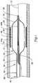
- Figure 1is a partial cross-sectional side view of an example catheter 10 disposed in a blood vessel 12 and positioned adjacent an intravascular lesion 14.
- Catheter 10includes a balloon 16 coupled to a catheter shaft 18.
- One or more cutting members or blades 20are coupled to balloon 16.
- catheter 10may be advanced over a guidewire 22, through the vasculature, to a target area.
- Balloon 16can then be inflated to expand lesion 14, and cutting members 20 may cut lesion 14.
- the target areamay be within any suitable peripheral or cardiac vessel lumen location.
- Cutting members 20may vary in number, position, and arrangement about balloon 16.
- catheter 10may include one, two, three, four, five, six, or more cutting members 20 that are disposed at any position along balloon 16 and in a regular, irregular, or any other suitable pattern.
- cutting members 20may be configured to be have variable flexibility or otherwise vary the flexibility of catheter 10. Increasing the flexibility of cutting members 20 and/or catheter 10 may be desirable, for example, because it may improve the tracking ability and general deliverability of catheter 10 through the often tortuous anatomy. Additionally, increasing the flexibility may allow catheter 10 to be navigable to a larger number of intravascular locations, including some that may not be readily reachable by other, less flexible, cutting balloon catheters.
- cutting members 20include a first section 44a, a second section 44b, and a bridge or bridge section 46 disposed between first section 44a and second section 44b.
- Bridge 46is configured to separate from first section 44a, second section 44b, or both. Separation of bridge 46 from sections 44a/b can increase the flexibility of cutting member 20 and/or the overall flexibility of catheter 10.
- Cutting members 20may be made from any suitable material such as a metal, metal alloy, polymer, metal-polymer composite, and the like, or any other suitable material.
- cutting members 20may be made from stainless steel such as 304V, 304L, or 316L stainless steel.
- cutting member 20can be made from a glass/KEVLAR® complex material such as ARAMAT®, which is commercially available.
- Balloon 16may be made from typical angioplasty balloon materials including polymers such as polyethylene terephthalate (PET), polyetherimid (PEI), polyethylene (PE), etc.
- suitable polymersincluding lubricious polymers, may include polytetrafluoroethylene (PTFE), ethylene tetrafluoroethylene (ETFE), fluorinated ethylene propylene (FEP), polyoxymethylene (POM), polybutylene terephthalate (PBT), polyether block ester, polyurethane, polypropylene (PP), polyvinylchloride (PVC), polyether-ester (for example, a polyether-ester elastomer such as ARNITEL® available from DSM Engineering Plastics), polyester (for example, a polyester elastomer such as HYTREL® available from DuPont), polyamide (for example, DURETHAN® available from Bayer or CRISTAMID® available from Elf Atochem), elastomeric polyamides, block polymers
- the above list of materialsincludes some examples of higher modulus materials.
- Some other examples of stiffer materialsinclude polymers blended with liquid crystal polymer (LCP) as well as the materials listed above.
- LCPliquid crystal polymer
- the mixturecan contain up to about 5% LCP.
- Balloon 16may be configured so that it includes one or more "wings" or wing-shaped regions when balloon 16 is deflated. These wings may appear as a plurality of alternating inward and outward radial deflections in balloon 16 when balloon 16 is deflated. These wings may be desirable for a number of reasons. For example, by including balloon 16 with wings, balloon 16 may have more predictable and consistent re-folding characteristics. Additionally, the wings may be configured so that cutting members 20 can be positioned at the inward-most positions of the deflated balloon 16. This arrangement allows cutting members 20 to be positioned more closely to shaft 18 when balloon 16 is deflated.
- cutting members 20can be moved away from the vessel walls where they might otherwise result in contact and, possibly, damage to healthy tissue during movement of catheter 10 within a body lumen. Additionally, alternating the wings and cutting members 20 as well as positioning cutting members 20 relatively close to shaft 18 may allow the wings to fold over and cover cutting members 20 when balloon 16 is deflated. Again, this feature may reduce the exposure of cutting members 20 to the blood vessel.
- Shaft 18may be a catheter shaft, similar to typical catheter shafts.
- shaft 18may include an inner tubular member 24 and outer tubular member 26.
- Tubular members 24/26may be manufactured from a number of different materials.
- tubular members 24/26may be made of metals, metal alloys, polymers, metal-polymer composites or any other suitable materials.
- suitable metals and metal alloysinclude stainless steel, such as 300 series stainless steel (including 304V, 304L, and 316L); 400 series martensitic stainless steel; tool steel; nickel-titanium alloy such as linear-elastic or super-elastic Nitinol, nickel-chromium alloy, nickel-chromium-iron alloy, cobalt alloy, tungsten or tungsten alloys, MP35-N (having a composition of about 35% Ni, 35% Co, 20% Cr, 9.75% Mo, a maximum 1% Fe, a maximum 1% Ti, a maximum 0.25% C, a maximum 0.15% Mn, and a maximum 0.15% Si), hastelloy, monel 400, inconel 825, or the like; or other suitable material.
- stainless steelsuch as 300 series stainless steel (including 304V, 304L, and 316L); 400 series martensitic stainless steel; tool steel; nickel-titanium alloy such as linear-elastic or super-elastic
- suitable polymersinclude those described above in relation to balloon 16. Of course, any other polymer or other suitable material including ceramics may be used without departing from the spirit of the invention.
- the materials used to manufacture inner tubular member 24may be the same as or be different from the materials used to manufacture outer tubular member 26. Those materials listed herein may also be used for manufacturing other components of catheter 10 including cutting members 20.
- Tubular members 24/26may be arranged in any appropriate way.
- inner tubular member 24can be disposed coaxially within outer tubular member 26.
- inner and outer tubular members 24/26may or may not be secured to one another along the general longitudinal axis of shaft 18.
- inner tubular member 24may follow the inner wall or otherwise be disposed adjacent the inner wall of outer tubular member 26.
- inner and outer tubular members 24/26may or may not be secured to one another.
- inner and outer tubular members 24/26may be bonded, welded (including tack welding or any other welding technique), or otherwise secured at a bond point.
- the bond pointmay be generally disposed near the distal end of shaft 18.
- one or more bond pointsmay be disposed at any position along shaft 18.
- the bondmay desirably impact, for example, the stability and the ability of tubular members 24/26 to maintain their position relative to one another.
- inner and outer tubular member 24/26may be adjacent to and substantially parallel to one another so that they are non-overlapping.
- shaft 18may include an outer sheath that is disposed over tubular members 24/26.
- Inner tubular member 24may include an inner lumen 28.
- inner lumen 28is a guidewire lumen. Accordingly, catheter 10 can be advanced over guidewire 22 to the desired location.
- the guidewire lumenmay extend along essentially the entire length of catheter shaft 18 so that catheter 10 resembles a traditional "over-the-wire" catheter. Alternatively, the guidewire lumen may extend along only a portion of shaft 18 so that catheter 10 resembles a "single-operator-exchange" or "rapid-exchange” catheter.
- catheter 10may be configured so that balloon 16 is disposed over at least a region of inner lumen 28.
- inner lumen 28i.e., the portion of inner lumen 28 that balloon 16 is disposed over
- Shaft 18may also include an inflation lumen 30 that may be used, for example, to transport inflation media to and from balloon 16.
- inflation lumen 30may vary, depending on the configuration of tubular members 24/26. For example, when outer tubular member 26 is disposed over inner tubular member 24, inflation lumen 30 may be defined within the space between tubular members 24/26.
- shape of lumen 30i.e., the shape adjacent shaft 18 may vary.
- inflation lumen 30may be generally half-moon in shape; whereas, if inner tubular member 24 is generally coaxial with outer tubular member 26, then inflation lumen 30 may be generally ring-shaped or annular in shape. It can be appreciated that if outer tubular member 26 is disposed alongside inner tubular member 24, then lumen 30 may be the lumen of outer tubular member 26 or it may be the space defined between the outer surface of tubular members 24/26 and the outer sheath disposed thereover.
- Balloon 16may be coupled to catheter shaft 18 in any of a number of suitable ways.
- balloon 16may be adhesively or thermally bonded to shaft 18.
- a proximal waist 32 of balloon 16may be bonded to shaft 18, for example, at outer tubular member 26, and a distal waist 34 may be bonded to shaft 18, for example, at inner tubular member 24.
- the exact bonding positions, however,may vary. It can be appreciated that a section of proximal waist 32 may not have sections 36 extending therefrom in order for suitable bonding between balloon 16 and outer tubular member 30.
- shaft 18may also include a number of other structural elements, including those typically associated with catheter shafts.
- shaft 18may include a radiopaque marker coupled thereto that may aid a user in determining the location of catheter 10 within the vasculature.
- catheter 10may include a folding spring (not shown) coupled to balloon 16, for example, adjacent proximal waist 32, which may further help in balloon folding and refolding.
- a folding springcan be found in U.S. Patent No. 6,425,882 .
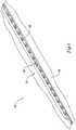
- FIG. 2An exploded view illustrating the attachment of cutting members 20 to balloon 16 is shown in Figure 2 .
- a joining member or polymeric strip 38is coupled to cutting member 20 and to balloon 16.
- Joining member 38may be formed from a generally flexible or soft material that allows the interface between cutting member 20 and balloon 16 to be somewhat elastic or pliable.
- joining member 38may be manufactured from a low durometer polyurethane or any other suitable material (including any of the polymers and other materials disclosed herein). Accordingly, cutting member 20 may be securely coupled to balloon 16 while still being able to move laterally about eight degrees or less. In addition, different portions of cutting member 20 may be able to bend or flex, while other portions remain essentially unchanged.
- joining member 38is attached to and disposed between cutting member 20 and balloon 16.
- joining member 38can be attached to an outer surface 40 of balloon 16 and to a base 50 of the cutting member 20.
- the attachment of joining member 38 with cutting member 20 and balloon 16may be achieved in any appropriate manner, such as by adhesive bonding, casting, thermal bonding, mechanically connecting, welding, brazing, and the like, or in any other suitable way.
- the attachment meansneed not be the same for the attachment between cutting member 20 and joining member 38 as the means used to attach balloon 16 and joining member 38.
- bridge 46may be defined by a downward deflection or slot that is formed in the cutting surface 48 of cutting member 20.
- this particular exampleis not intended to be limiting, because bridge 46 can be defined in a number of alternative manners.
- bridge 46may comprise an exogenous connector that is connected to both first section 44a and second section 44b in order to connect sections 44a/44b.
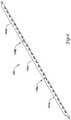
- cutting member 20may include a cutting surface 48 and base 50.
- cutting member 20may also include a series of alternating tabs 52 and holes or openings 54 that are disposed along the base 50 of cutting member 20.
- Tabs 52 and openings 54may be formed in any suitable manner, such as with a wire electric discharge milling technique or any other suitable methodology.
- Tabs 52 and openings 54may have a number of functions.
- openings 54(or, more precisely, the portions of cutting member 20 adjacent openings 54) may provide a location for an adhesive (e.g., polyurethane or any other suitable material) or polymer strip 38 to flow into so as to improve the bonding of cutting member 20 with balloon 16.
- an adhesivee.g., polyurethane or any other suitable material
- the bonding media(e.g., polymeric strip 38) may encapsulate the base 50 of cutting member 20 and, thus, may interlock with cutting member 20 so as to improve the bonding between balloon 16 and cutting member 20. This feature is better seen in Figures 5 and 6 .
- tabs 52 and openings 54may desirably impact the flexibility of cutting member 20. Additionally, the shape of tabs 52 and opening 54 may vary. For example, tabs 52 may have a shape similar to an inverted T (when viewed from the side) or otherwise have a splayed pillar-like shape, and openings 54 may be somewhat rounded or oval. It can be appreciated, however, that tabs 52 and openings 54 are not intended to be limited to these or any other particular shape. Moreover, the size and number of tabs 52 and openings 54 may also vary, typically in relation to the length of cutting member 20.
- openings 54may have a height in the range of about 0.0508 to about 0.254 mm (about 0.002 to about 0.010 inches) and a width in the range of about 0.1778 to about 0.381 mm (about 0.007 to about 0.015 inches).
- bridge 46may be defined by a downward deflection in cutting surface 48 of cutting member 20.
- the bottom 56 of bridge 46may also be spatially altered.
- Figure 4illustrates that the bottom 56 of bridge 46 may be raised a distance D relative to the base 50 of cutting member 20.
- Distance Dmay be about 0.00254 to about 0.254mm (about 0.0001 inches to about 0.010 inches). This feature may be desirable, for example, because it raises bridge 46 up from balloon 16 (when cutting member 20 is coupled to balloon 16) so that bridge 46 is spatially separated from balloon 16 when bridge 46 separates from first section 44a, second section 44b, or both.
- bridge 46Prior to inserting catheter 10 into the body of a patient, bridge 46 is connected with both first section 44a and 44b, as shown in Figure 5 .
- This featureallows cutting member 20 to be longitudinally continuous so as to provide a desirable amount of pushability to catheter 10 when, for example, advancing catheter 10 through the vasculature.
- Some interventions, however,will require that catheter 10 pass through a bend in the vasculature. In some instances, the bend may be significant so that only devices having a certain amount of flexibility can be easily navigated through the bend.
- Catheter 10is configured to be adaptable to changes in the vasculature by being able to vary its flexibility. This variability allows catheter 10 to be easily navigated through tortuous sections of the vasculature.
- Varying the flexibility of catheter 10may be accomplished by the inclusion of bridge 46.
- bridge 46may be configured to fracture or separate from first section 44a, second section 44b, or both, as shown in Figure 6 .
- the bridgecan include a polymer that is soluble in the environment of use, which in turn weakens the bridge, resulting in yielding in response to the vascular curvature. Accordingly, when catheter 10 encounters a sufficient bend in the vasculature, bridge 46 can separate from first section 44a, second section 44b, or both, thereby increasing the flexibility of cutting member 20 and catheter 10. This increase in flexibility allows catheter 10 to be navigated through the bend in the vasculature and, ultimately, to the final target area. Therefore, catheter 10 is adaptable to varying vasculature conditions and possesses the desired amount of pushability and flexibility when needed for the particular conditions encountered.
- bridge 46is shown in Figures 6 and 7 .
- bridge 46is shown in Figures 6 and 7 as being separated from both first section 44a and second section 44b, this is not intended to be limiting as bridge 46 may separate from only one of sections 44a/b.
- bridge 46is configured to separate from first section 44a, second section 44b, or both after catheter 10 is inserted into the body (e.g., the vasculature) of a patient. For example, bridge 46 may separate when catheter 10 encounters a bend in the vasculature as described above.
- bridge 46allows the separation to be isolated at the bottom 56 of bridge 46 and, thus, the bottom or base 50 of cutting member 20. Therefore, polymer strip 38 at the base 50 of cutting member 20 can surround the separated segments 58 of bridge 46 and shield balloon 16, other portions of the catheter 10, and surrounding tissue from unintentional damage that might otherwise occur if not shielded. The raising of the bottom 56 of bridge 46 can also contribute to this shielding effect by raising bottom 56 away from balloon 16.
- the length of cutting member 20, and the number and position of bridge 46may vary.
- the length of cutting member 20may range from about 4 millimeters to about 20 millimeter or so.
- the number of sections (e.g., sections 44a/b) and bridges (e.g., bridge 46) that can be includedalso increases.
- relatively short or moderate cutting memberse.g., about 4-14 millimeters
- Longer cutting memberse.g., about 12 millimeters or longer
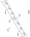
- Figure 8illustrates cutting member 120 that has two bridges 146a/b.
- Bridge 146ais disposed between first section 144a and second section 144b.
- Bridge 146bis disposed between second section 144b and a third section 144c.
- additional embodiments of cutting membersare contemplated that have a variety of lengths and a various numbers of bridges and sections.
- Figures 9-12illustrate alternative example cutting members for use with any suitable cutting balloon catheter.
- Figure 9illustrates cutting member 220 (which is similar to cutting member 20) that has a thinned base or bottom 256. Although this may be somewhat difficult to see in Figure 9 alone, the thinning of base 256 can be more easily visualized by comparing the thickness of base 256 in Figure 9 with the thickness of base 356 in Figure 10 .
- the thinning featuremay enhance the ability of cutting member 220 to fracture or separate from sections 244a/b, which may be desirable for some interventions.
- the example cutting member 320 depicted in Figure 10has a hole or opening 360 defined in bridge 346. Hole 360 may similarly enhance the ability of cutting member 220 to separate.
- Figure 1-1illustrates cutting member 420 that has one or more etches formed in bridge 446 that can enhance the ability of cutting member 420 to separate.
- Figure 12illustrates another example cutting member 520 where bridge 546 is defined by a general thinning of cutting member 520 between sections 544a/b. Thinned bridge 546 can be formed with a wire electric discharge method or with other suitable methods such as grinding, machining, and the like.
Landscapes
- Health & Medical Sciences (AREA)
- Life Sciences & Earth Sciences (AREA)
- Heart & Thoracic Surgery (AREA)
- Animal Behavior & Ethology (AREA)
- Surgery (AREA)
- Veterinary Medicine (AREA)
- Engineering & Computer Science (AREA)
- Public Health (AREA)
- Biomedical Technology (AREA)
- General Health & Medical Sciences (AREA)
- Pulmonology (AREA)
- Hematology (AREA)
- Anesthesiology (AREA)
- Biophysics (AREA)
- Vascular Medicine (AREA)
- Nuclear Medicine, Radiotherapy & Molecular Imaging (AREA)
- Child & Adolescent Psychology (AREA)
- Medical Informatics (AREA)
- Molecular Biology (AREA)
- Surgical Instruments (AREA)
Description
- The present invention pertains to angioplasty and angioplasty balloon catheters. More particularly, the present invention pertains to angioplasty balloon catheters that include one or more cutting blades coupled to the angioplasty balloon.
- Heart and vascular disease are major problems in the United States and throughout the world. Conditions such as atherosclerosis result in blood vessels becoming blocked or narrowed. This blockage can result in lack of oxygenation of the heart, which has significant consequences, since the heart muscle must be well oxygenated in order to maintain its blood pumping action.
- Occluded, stenotic, or narrowed blood vessels may be treated with a number of relatively non-invasive medical procedures including percutaneous transluminal angioplasty (PTA), percutaneous transluminal coronary angioplasty (PTCA), and atherectomy. Angioplasty techniques typically involve the use of a balloon catheter. The balloon catheter is advanced over a guidewire so that the balloon is positioned adjacent a stenotic lesion. The balloon is then inflated, and the restriction of the vessel is opened.
- One of the major obstacles in treating coronary artery disease and/or treating blocked blood vessels is re-stenosis. Evidence has shown that cutting the stenosis, for example, with an angioplasty balloon equipped with a cutting blade during treatment, can reduce incidence of re-stenosis. Additionally, cutting the stenosis may reduce trauma at the treatment site and/or may reduce the trauma to adjacent healthy tissue. Cutting blades may also be beneficial additions to angioplasty procedures when the targeted occlusion is hardened or calcified. It is believed typical angioplasty balloons, alone, may not be able to expand certain of these hardened lesions. Thus, angioplasty balloons equipped with cutting edges have been developed to attempt to enhance angioplasty treatments. There is an ongoing need for improved angioplasty devices, including cutting angioplasty balloons, and improved methods of treating intravascular stenoses and occlusions.
US 2002/010489 A1 discloses a stiffened balloon which can be used in angioplasty, endovascular, and valvuloplasty procedures, or as a delivery balloon to deliver a stent or a stent-graft. Longitudinally discontinuous stiffening members connected to the expandable balloon stiffen the balloon but allow it to be navigated through curved passages. Projections on the stiffening members may engage, incise, crush, fracture, or pierce occlusions or retain a stent or stent-graft.EP 0 565 796 A discloses a stenotic dilation device including a plurality of elongated atherotomes with cutters mounted on the outer surface of a flexible balloon along predetermined crease lines. The atherotomes are aligned along the longitudinal axis of the catheter. On inflation of the balloon at a stenotic site, the atherotomes are urged against the stenosis to incise the stenosis.- The present invention relates to a medical device as defined in the claims. Specifically, the present invention relates to angioplasty balloon catheters. In at least some embodiments, an example balloon catheter includes a catheter shaft having a balloon coupled thereto. One or more cutting members or blades are coupled to the balloon. The cutting members include a first section, a second section, and a bridge section disposed between the first and second sections. The bridge section is designed to yield, fracture or separate from the first section, second section, or both when the catheter is disposed within the body. These and other features are described in more detail below.
Figure 1 is a partial cross-sectional side view of an example cutting balloon catheter disposed in a blood vessel;Figure 2 is a partial perspective view of a representative cutting member and a joining member for connecting the cutting member to a balloon;Figure 3 is a perspective view of the cutting member ofFigure 2 ;Figure 4 is an enlarged perspective view of a bridge portion included in the cutting member shown inFigure 3 ;Figure 5 is a cutaway perspective view of a portion of the cutting member shown attached to a balloon;Figure 6 is a cutaway perspective view of a portion of the cutting member shown attached to a balloon where the bridge is separated from a first section and a second section of the cutting member;Figure 7 is an enlarged view of the bridge inFigure 6 as separated from the first section and the second section of the cutting member;Figure 8 is a perspective view of another example cutting member;Figure 9 is a perspective view of another example cutting member;Figure 10 is a perspective view of another example cutting member;Figure 11 is a perspective view of another example cutting member; andFigure 12 is a perspective view of another example cutting member.- The following description should be read with reference to the drawings wherein like reference numerals indicate like elements throughout the several views. The detailed description and drawings illustrate example embodiments of the claimed invention.
Figure 1 is a partial cross-sectional side view of anexample catheter 10 disposed in ablood vessel 12 and positioned adjacent anintravascular lesion 14.Catheter 10 includes aballoon 16 coupled to acatheter shaft 18. One or more cutting members orblades 20 are coupled toballoon 16. In general,catheter 10 may be advanced over aguidewire 22, through the vasculature, to a target area.Balloon 16 can then be inflated to expandlesion 14, and cuttingmembers 20 may cutlesion 14. The target area may be within any suitable peripheral or cardiac vessel lumen location.- Cutting
members 20 may vary in number, position, and arrangement aboutballoon 16. For example,catheter 10 may include one, two, three, four, five, six, or more cuttingmembers 20 that are disposed at any position alongballoon 16 and in a regular, irregular, or any other suitable pattern. In general, cuttingmembers 20 may be configured to be have variable flexibility or otherwise vary the flexibility ofcatheter 10. Increasing the flexibility of cuttingmembers 20 and/orcatheter 10 may be desirable, for example, because it may improve the tracking ability and general deliverability ofcatheter 10 through the often tortuous anatomy. Additionally, increasing the flexibility may allowcatheter 10 to be navigable to a larger number of intravascular locations, including some that may not be readily reachable by other, less flexible, cutting balloon catheters. In general, the enhanced flexibility is the result of a structural feature of cuttingmembers 20 or a structural modification to cuttingmembers 20. For example, cuttingmembers 20 include afirst section 44a, asecond section 44b, and a bridge orbridge section 46 disposed betweenfirst section 44a andsecond section 44b.Bridge 46 is configured to separate fromfirst section 44a,second section 44b, or both. Separation ofbridge 46 fromsections 44a/b can increase the flexibility of cuttingmember 20 and/or the overall flexibility ofcatheter 10. Some further discussion of this and other examples, features, and modifications are described in more detail below. - Cutting
members 20 may be made from any suitable material such as a metal, metal alloy, polymer, metal-polymer composite, and the like, or any other suitable material. For example, cuttingmembers 20 may be made from stainless steel such as 304V, 304L, or 316L stainless steel. In other embodiments, cuttingmember 20 can be made from a glass/KEVLAR® complex material such as ARAMAT®, which is commercially available. Some examples of other suitable materials are listed below in relation toballoon 16 andshaft 18. Balloon 16 may be made from typical angioplasty balloon materials including polymers such as polyethylene terephthalate (PET), polyetherimid (PEI), polyethylene (PE), etc. Some other examples of suitable polymers, including lubricious polymers, may include polytetrafluoroethylene (PTFE), ethylene tetrafluoroethylene (ETFE), fluorinated ethylene propylene (FEP), polyoxymethylene (POM), polybutylene terephthalate (PBT), polyether block ester, polyurethane, polypropylene (PP), polyvinylchloride (PVC), polyether-ester (for example, a polyether-ester elastomer such as ARNITEL® available from DSM Engineering Plastics), polyester (for example, a polyester elastomer such as HYTREL® available from DuPont), polyamide (for example, DURETHAN® available from Bayer or CRISTAMID® available from Elf Atochem), elastomeric polyamides, block polyamide/ethers, polyether block amide (PEBA, for example, available under the trade name PEBAX®), silicones, Marlex high-density polyethylene, Marlex low-density polyethylene, linear low density polyethylene (for example, REXELL®), polyetheretherketone (PEEK), polyimide (PI), polyphenylene sulfide (PPS), polyphenylene oxide (PPO), polysulfone, nylon, perfluoro(propyl vinyl ether) (PFA), other suitable materials, or mixtures, combinations, copolymers thereof, polymer/metal composites, and the like. In some embodiments, it may be desirable to use high modulus or generally stiffer materials so as to reduce balloon elongation. The above list of materials includes some examples of higher modulus materials. Some other examples of stiffer materials include polymers blended with liquid crystal polymer (LCP) as well as the materials listed above. For example, the mixture can contain up to about 5% LCP.Balloon 16 may be configured so that it includes one or more "wings" or wing-shaped regions whenballoon 16 is deflated. These wings may appear as a plurality of alternating inward and outward radial deflections inballoon 16 whenballoon 16 is deflated. These wings may be desirable for a number of reasons. For example, by includingballoon 16 with wings,balloon 16 may have more predictable and consistent re-folding characteristics. Additionally, the wings may be configured so that cuttingmembers 20 can be positioned at the inward-most positions of the deflatedballoon 16. This arrangement allows cuttingmembers 20 to be positioned more closely toshaft 18 whenballoon 16 is deflated. Accordingly, cuttingmembers 20 can be moved away from the vessel walls where they might otherwise result in contact and, possibly, damage to healthy tissue during movement ofcatheter 10 within a body lumen. Additionally, alternating the wings and cuttingmembers 20 as well as positioning cuttingmembers 20 relatively close toshaft 18 may allow the wings to fold over andcover cutting members 20 whenballoon 16 is deflated. Again, this feature may reduce the exposure of cuttingmembers 20 to the blood vessel.Shaft 18 may be a catheter shaft, similar to typical catheter shafts. For example,shaft 18 may include aninner tubular member 24 and outertubular member 26.Tubular members 24/26 may be manufactured from a number of different materials. For example,tubular members 24/26 may be made of metals, metal alloys, polymers, metal-polymer composites or any other suitable materials. Some examples of suitable metals and metal alloys include stainless steel, such as 300 series stainless steel (including 304V, 304L, and 316L); 400 series martensitic stainless steel; tool steel; nickel-titanium alloy such as linear-elastic or super-elastic Nitinol, nickel-chromium alloy, nickel-chromium-iron alloy, cobalt alloy, tungsten or tungsten alloys, MP35-N (having a composition of about 35% Ni, 35% Co, 20% Cr, 9.75% Mo, a maximum 1% Fe, a maximum 1% Ti, a maximum 0.25% C, a maximum 0.15% Mn, and a maximum 0.15% Si), hastelloy, monel 400, inconel 825, or the like; or other suitable material. Some examples of suitable polymers include those described above in relation toballoon 16. Of course, any other polymer or other suitable material including ceramics may be used without departing from the spirit of the invention. The materials used to manufacture innertubular member 24 may be the same as or be different from the materials used to manufacture outertubular member 26. Those materials listed herein may also be used for manufacturing other components ofcatheter 10 including cuttingmembers 20.Tubular members 24/26 may be arranged in any appropriate way. For example, in some embodiments,inner tubular member 24 can be disposed coaxially within outertubular member 26. According to these embodiments, inner and outertubular members 24/26 may or may not be secured to one another along the general longitudinal axis ofshaft 18. Alternatively,inner tubular member 24 may follow the inner wall or otherwise be disposed adjacent the inner wall of outertubular member 26. Again, inner and outertubular members 24/26 may or may not be secured to one another. For example, inner and outertubular members 24/26 may be bonded, welded (including tack welding or any other welding technique), or otherwise secured at a bond point. In some embodiments, the bond point may be generally disposed near the distal end ofshaft 18. However, one or more bond points may be disposed at any position alongshaft 18. The bond may desirably impact, for example, the stability and the ability oftubular members 24/26 to maintain their position relative to one another. In still other embodiments, inner and outertubular member 24/26 may be adjacent to and substantially parallel to one another so that they are non-overlapping. In these embodiments,shaft 18 may include an outer sheath that is disposed overtubular members 24/26.- Inner
tubular member 24 may include aninner lumen 28. In at least some embodiments,inner lumen 28 is a guidewire lumen. Accordingly,catheter 10 can be advanced overguidewire 22 to the desired location. The guidewire lumen may extend along essentially the entire length ofcatheter shaft 18 so thatcatheter 10 resembles a traditional "over-the-wire" catheter. Alternatively, the guidewire lumen may extend along only a portion ofshaft 18 so thatcatheter 10 resembles a "single-operator-exchange" or "rapid-exchange" catheter. Regardless of which type of catheter is contemplated,catheter 10 may be configured so thatballoon 16 is disposed over at least a region ofinner lumen 28. In at least some of these embodiments, inner lumen 28 (i.e., the portion ofinner lumen 28 thatballoon 16 is disposed over) may be substantially coaxial withballoon 16. Shaft 18 may also include aninflation lumen 30 that may be used, for example, to transport inflation media to and fromballoon 16. The location and position ofinflation lumen 30 may vary, depending on the configuration oftubular members 24/26. For example, when outertubular member 26 is disposed over innertubular member 24,inflation lumen 30 may be defined within the space betweentubular members 24/26. Moreover, depending on the position of innertubular member 24 within outertubular member 26, the shape of lumen 30 (i.e., the shape adjacent shaft 18) may vary. For example, if innertubular member 24 is attached to or disposed adjacent to the inside surface of outertubular member 26, theninflation lumen 30 may be generally half-moon in shape; whereas, if innertubular member 24 is generally coaxial with outertubular member 26, theninflation lumen 30 may be generally ring-shaped or annular in shape. It can be appreciated that if outertubular member 26 is disposed alongside innertubular member 24, then lumen 30 may be the lumen of outertubular member 26 or it may be the space defined between the outer surface oftubular members 24/26 and the outer sheath disposed thereover.Balloon 16 may be coupled tocatheter shaft 18 in any of a number of suitable ways. For example,balloon 16 may be adhesively or thermally bonded toshaft 18. In some embodiments, aproximal waist 32 ofballoon 16 may be bonded toshaft 18, for example, at outertubular member 26, and adistal waist 34 may be bonded toshaft 18, for example, at innertubular member 24. The exact bonding positions, however, may vary. It can be appreciated that a section ofproximal waist 32 may not havesections 36 extending therefrom in order for suitable bonding betweenballoon 16 and outertubular member 30.- In addition to some of the structures described above,
shaft 18 may also include a number of other structural elements, including those typically associated with catheter shafts. For example,shaft 18 may include a radiopaque marker coupled thereto that may aid a user in determining the location ofcatheter 10 within the vasculature. In addition,catheter 10 may include a folding spring (not shown) coupled toballoon 16, for example, adjacentproximal waist 32, which may further help in balloon folding and refolding. A description of a suitable folding spring can be found inU.S. Patent No. 6,425,882 . - An exploded view illustrating the attachment of cutting
members 20 to balloon 16 is shown inFigure 2 . Here it can be seen that a joining member orpolymeric strip 38 is coupled to cuttingmember 20 and to balloon 16. Joiningmember 38 may be formed from a generally flexible or soft material that allows the interface between cuttingmember 20 andballoon 16 to be somewhat elastic or pliable. For example, joiningmember 38 may be manufactured from a low durometer polyurethane or any other suitable material (including any of the polymers and other materials disclosed herein). Accordingly, cuttingmember 20 may be securely coupled toballoon 16 while still being able to move laterally about eight degrees or less. In addition, different portions of cuttingmember 20 may be able to bend or flex, while other portions remain essentially unchanged. According to the invention, joiningmember 38 is attached to and disposed between cuttingmember 20 andballoon 16. For example, joiningmember 38 can be attached to anouter surface 40 ofballoon 16 and to abase 50 of the cuttingmember 20. The attachment of joiningmember 38 with cuttingmember 20 andballoon 16 may be achieved in any appropriate manner, such as by adhesive bonding, casting, thermal bonding, mechanically connecting, welding, brazing, and the like, or in any other suitable way. The attachment means need not be the same for the attachment between cuttingmember 20 and joiningmember 38 as the means used to attachballoon 16 and joiningmember 38. - A more detailed view of cutting
member 20 is shown inFigure 3 . Here,first section 44a,second section 44b, andbridge 46 can be more clearly seen. In at least some embodiments,bridge 46 may be defined by a downward deflection or slot that is formed in the cuttingsurface 48 of cuttingmember 20. However, this particular example is not intended to be limiting, becausebridge 46 can be defined in a number of alternative manners. For example,bridge 46 may comprise an exogenous connector that is connected to bothfirst section 44a andsecond section 44b in order to connectsections 44a/44b. Some other examples are shown in later figures and described below. - Some of the other features of cutting
member 20 can also be seen inFigure 3 . For example, cuttingmember 20 may include a cuttingsurface 48 andbase 50. Moreover, cuttingmember 20 may also include a series of alternatingtabs 52 and holes oropenings 54 that are disposed along thebase 50 of cuttingmember 20.Tabs 52 andopenings 54 may be formed in any suitable manner, such as with a wire electric discharge milling technique or any other suitable methodology.Tabs 52 andopenings 54 may have a number of functions. For example, openings 54 (or, more precisely, the portions of cuttingmember 20 adjacent openings 54) may provide a location for an adhesive (e.g., polyurethane or any other suitable material) orpolymer strip 38 to flow into so as to improve the bonding of cuttingmember 20 withballoon 16. The bonding media (e.g., polymeric strip 38) may encapsulate thebase 50 of cuttingmember 20 and, thus, may interlock with cuttingmember 20 so as to improve the bonding betweenballoon 16 and cuttingmember 20. This feature is better seen inFigures 5 and6 . - In some embodiments,
tabs 52 andopenings 54 may desirably impact the flexibility of cuttingmember 20. Additionally, the shape oftabs 52 andopening 54 may vary. For example,tabs 52 may have a shape similar to an inverted T (when viewed from the side) or otherwise have a splayed pillar-like shape, andopenings 54 may be somewhat rounded or oval. It can be appreciated, however, thattabs 52 andopenings 54 are not intended to be limited to these or any other particular shape. Moreover, the size and number oftabs 52 andopenings 54 may also vary, typically in relation to the length of cuttingmember 20. For example,openings 54 may have a height in the range of about 0.0508 to about 0.254 mm (about 0.002 to about 0.010 inches) and a width in the range of about 0.1778 to about 0.381 mm (about 0.007 to about 0.015 inches). - As described above,
bridge 46 may be defined by a downward deflection in cuttingsurface 48 of cuttingmember 20. In addition to this, the bottom 56 ofbridge 46 may also be spatially altered. For example,Figure 4 illustrates that the bottom 56 ofbridge 46 may be raised a distance D relative to thebase 50 of cuttingmember 20. Distance D may be about 0.00254 to about 0.254mm (about 0.0001 inches to about 0.010 inches). This feature may be desirable, for example, because it raisesbridge 46 up from balloon 16 (when cuttingmember 20 is coupled to balloon 16) so thatbridge 46 is spatially separated fromballoon 16 whenbridge 46 separates fromfirst section 44a,second section 44b, or both. - Prior to inserting
catheter 10 into the body of a patient,bridge 46 is connected with bothfirst section Figure 5 . This feature allows cuttingmember 20 to be longitudinally continuous so as to provide a desirable amount of pushability tocatheter 10 when, for example, advancingcatheter 10 through the vasculature. Some interventions, however, will require thatcatheter 10 pass through a bend in the vasculature. In some instances, the bend may be significant so that only devices having a certain amount of flexibility can be easily navigated through the bend.Catheter 10 is configured to be adaptable to changes in the vasculature by being able to vary its flexibility. This variability allowscatheter 10 to be easily navigated through tortuous sections of the vasculature. Varying the flexibility ofcatheter 10 may be accomplished by the inclusion ofbridge 46. For example,bridge 46 may be configured to fracture or separate fromfirst section 44a,second section 44b, or both, as shown inFigure 6 . Alternatively, the bridge can include a polymer that is soluble in the environment of use, which in turn weakens the bridge, resulting in yielding in response to the vascular curvature. Accordingly, whencatheter 10 encounters a sufficient bend in the vasculature,bridge 46 can separate fromfirst section 44a,second section 44b, or both, thereby increasing the flexibility of cuttingmember 20 andcatheter 10. This increase in flexibility allowscatheter 10 to be navigated through the bend in the vasculature and, ultimately, to the final target area. Therefore,catheter 10 is adaptable to varying vasculature conditions and possesses the desired amount of pushability and flexibility when needed for the particular conditions encountered. - The separation of
bridge 46 fromfirst section 44a andsecond section 44b is shown inFigures 6 and7 . Althoughbridge 46 is shown inFigures 6 and7 as being separated from bothfirst section 44a andsecond section 44b, this is not intended to be limiting asbridge 46 may separate from only one ofsections 44a/b. In at least some embodiments,bridge 46 is configured to separate fromfirst section 44a,second section 44b, or both aftercatheter 10 is inserted into the body (e.g., the vasculature) of a patient. For example,bridge 46 may separate whencatheter 10 encounters a bend in the vasculature as described above. - Turning now to
Figure 7 , it can be seen how the design ofbridge 46 allows the separation to be isolated at the bottom 56 ofbridge 46 and, thus, the bottom orbase 50 of cuttingmember 20. Therefore,polymer strip 38 at thebase 50 of cuttingmember 20 can surround the separatedsegments 58 ofbridge 46 andshield balloon 16, other portions of thecatheter 10, and surrounding tissue from unintentional damage that might otherwise occur if not shielded. The raising of the bottom 56 ofbridge 46 can also contribute to this shielding effect by raising bottom 56 away fromballoon 16. - It can be appreciated that the length of cutting
member 20, and the number and position ofbridge 46 may vary. For example, the length of cuttingmember 20 may range from about 4 millimeters to about 20 millimeter or so. Generally, as the length of cuttingmember 20 increases, the number of sections (e.g.,sections 44a/b) and bridges (e.g., bridge 46) that can be included also increases. Accordingly, relatively short or moderate cutting members (e.g., about 4-14 millimeters) may include one bridge similar tobridge 46. Longer cutting members (e.g., about 12 millimeters or longer) may include more than one bridge. For example,Figure 8 illustrates cuttingmember 120 that has twobridges 146a/b.Bridge 146a is disposed betweenfirst section 144a andsecond section 144b.Bridge 146b is disposed betweensecond section 144b and athird section 144c. Of course, a number of additional embodiments of cutting members are contemplated that have a variety of lengths and a various numbers of bridges and sections. Figures 9-12 illustrate alternative example cutting members for use with any suitable cutting balloon catheter. For example,Figure 9 illustrates cutting member 220 (which is similar to cutting member 20) that has a thinned base orbottom 256. Although this may be somewhat difficult to see inFigure 9 alone, the thinning ofbase 256 can be more easily visualized by comparing the thickness ofbase 256 inFigure 9 with the thickness ofbase 356 inFigure 10 . The thinning feature may enhance the ability of cuttingmember 220 to fracture or separate fromsections 244a/b, which may be desirable for some interventions. Theexample cutting member 320 depicted inFigure 10 has a hole or opening 360 defined inbridge 346.Hole 360 may similarly enhance the ability of cuttingmember 220 to separate. Likewise,Figure 1-1 illustrates cuttingmember 420 that has one or more etches formed inbridge 446 that can enhance the ability of cuttingmember 420 to separate. Finally,Figure 12 illustrates anotherexample cutting member 520 wherebridge 546 is defined by a general thinning of cuttingmember 520 betweensections 544a/b. Thinnedbridge 546 can be formed with a wire electric discharge method or with other suitable methods such as grinding, machining, and the like.- It should be understood that this disclosure is, in many respects, only illustrative. Changes may be made in details, particularly in matters of shape, size, and arrangement of steps without exceeding the scope of the invention. The invention's scope is, of course, defined in the language in which the appended claims are expressed.
Claims (12)
- A medical device, comprising:an elongate shaft (18) having a distal end region;a balloon (16) coupled to the distal end region;a cutting member (20, 120, 220, 320, 420, 520) coupled to the balloon, the cutting member having a cutting surface (48), a base (50), a first segment (44a, 144a, 244a, 544a), a second segment (44b, 144b, 244b, 544b), and a bridge segment (46, 146a, 246, 346, 446, 546) extending between the first segment and the second segment, wherein the bridge segment is configured to yield when flexed beyond a selected curvature during use; anda joining member (38) disposed adjacent the base of the cutting member and coupled to the balloon;wherein the joining member encapsulates the bridge segment;wherein the bridge segment is configured to separate from the first segment, the second segment, or both during use of the medical device.
- The medical device of claim 1, wherein the bridge segment is defined by a slot formed in the cutting surface.
- The medical device of claim 1, wherein the bridge segment has a base, and wherein the base of the bridge segment is thinned relative to the base of the cutting member.
- The medical device of claim 1, wherein the bridge segment has a base, and wherein the base of the bridge segment is raised relative to the base of the cutting member.
- The medical device of claim 1, wherein the bridge segment has a hole defined therein.
- The medical device of claim 1, wherein the bridge segment includes one or more etches formed therein.
- The medical device of claim 1, wherein the bridge segment is defined by an inward deflection formed in the cutting member.
- The medical device of claim 1, wherein the cutting member further comprises a third segment (144c) and a second bridge segment (146b) extending between the second segment and the third segment.
- The medical device of claim 1, wherein the cutting member includes a plurality of tabs (52) disposed along the base thereof.
- The medical device of claim 1, wherein the bridge segment remains encapsulated in the joining member when the bridge is separated from the first segment, the second segment, or both.
- The medical device of claim 1, wherein the joining member includes a polymer.
- The medical device of claim 1, further comprising one or more additional cutting members coupled to the balloon.
Applications Claiming Priority (2)
| Application Number | Priority Date | Filing Date | Title |
|---|---|---|---|
| US10/987,011US7291158B2 (en) | 2004-11-12 | 2004-11-12 | Cutting balloon catheter having a segmented blade |
| PCT/US2005/038753WO2006055206A1 (en) | 2004-11-12 | 2005-10-26 | Cutting balloon catheter having a segmented blade |
Publications (2)
| Publication Number | Publication Date |
|---|---|
| EP1809361A1 EP1809361A1 (en) | 2007-07-25 |
| EP1809361B1true EP1809361B1 (en) | 2018-03-21 |
Family
ID=35788853
Family Applications (1)
| Application Number | Title | Priority Date | Filing Date |
|---|---|---|---|
| EP05813772.0AActiveEP1809361B1 (en) | 2004-11-12 | 2005-10-26 | Cutting balloon catheter having a segmented blade |
Country Status (5)
| Country | Link |
|---|---|
| US (1) | US7291158B2 (en) |
| EP (1) | EP1809361B1 (en) |
| JP (1) | JP4929179B2 (en) |
| CA (1) | CA2584443C (en) |
| WO (1) | WO2006055206A1 (en) |
Families Citing this family (59)
| Publication number | Priority date | Publication date | Assignee | Title |
|---|---|---|---|---|
| US7976557B2 (en) | 2004-06-23 | 2011-07-12 | Boston Scientific Scimed, Inc. | Cutting balloon and process |
| US8038691B2 (en) | 2004-11-12 | 2011-10-18 | Boston Scientific Scimed, Inc. | Cutting balloon catheter having flexible atherotomes |
| US20060184191A1 (en) | 2005-02-11 | 2006-08-17 | Boston Scientific Scimed, Inc. | Cutting balloon catheter having increased flexibility regions |
| US7722674B1 (en)* | 2005-08-12 | 2010-05-25 | Innvotec Surgical Inc. | Linearly expanding spine cage for enhanced spinal fusion |
| US9028550B2 (en) | 2005-09-26 | 2015-05-12 | Coalign Innovations, Inc. | Selectively expanding spine cage with enhanced bone graft infusion |
| US8070813B2 (en) | 2005-09-26 | 2011-12-06 | Coalign Innovations, Inc. | Selectively expanding spine cage, hydraulically controllable in three dimensions for vertebral body replacement |
| US7985256B2 (en) | 2005-09-26 | 2011-07-26 | Coalign Innovations, Inc. | Selectively expanding spine cage, hydraulically controllable in three dimensions for enhanced spinal fusion |
| US20080077164A1 (en)* | 2006-02-24 | 2008-03-27 | National University Of Ireland, Galway | Minimally Invasive Intravascular Treatment Device |
| US7691116B2 (en)* | 2006-03-09 | 2010-04-06 | Boston Scientific Scimed, Inc. | Cutting blade for medical devices |
| US7842056B2 (en)* | 2007-05-18 | 2010-11-30 | Boston Scientific Scimed, Inc. | Cutting member for bifurcation catheter assembly |
| US20100145455A1 (en)* | 2008-12-10 | 2010-06-10 | Innvotec Surgical, Inc. | Lockable spinal implant |
| US12232975B2 (en) | 2008-02-22 | 2025-02-25 | Howmedica Osteonics Corp. | Lockable spinal implant |
| US8696751B2 (en) | 2008-12-10 | 2014-04-15 | Coalign Innovations, Inc. | Adjustable distraction cage with linked locking mechanisms |
| US8992620B2 (en) | 2008-12-10 | 2015-03-31 | Coalign Innovations, Inc. | Adjustable distraction cage with linked locking mechanisms |
| US8932355B2 (en) | 2008-02-22 | 2015-01-13 | Coalign Innovations, Inc. | Spinal implant with expandable fixation |
| WO2009114425A1 (en) | 2008-03-13 | 2009-09-17 | Cook Incorporated | Cutting balloon with connector and dilation element |
| US11229777B2 (en) | 2008-03-21 | 2022-01-25 | Cagent Vascular, Inc. | System and method for plaque serration |
| EP2254641B1 (en) | 2008-03-21 | 2016-09-21 | Cagent Vascular, LLC | Device for pre-angioplasty serration and dilatation |
| US9480826B2 (en) | 2008-03-21 | 2016-11-01 | Cagent Vascular, Llc | Intravascular device |
| US20100010521A1 (en)* | 2008-07-10 | 2010-01-14 | Cook Incorporated | Cutting balloon with movable member |
| US20100069837A1 (en)* | 2008-09-16 | 2010-03-18 | Boston Scientific Scimed, Inc. | Balloon Assembly and Method for Therapeutic Agent Delivery |
| US20100179517A1 (en)* | 2009-01-09 | 2010-07-15 | Jiro Takashima | Catheter |
| WO2010096570A2 (en)* | 2009-02-23 | 2010-08-26 | John To | Stent strut appositioner |
| IT1395280B1 (en) | 2009-08-12 | 2012-09-05 | London Equitable Ltd In Its Capacity As Trustee Of The Think Tank Trust | GROUP OF EXPANSION AND RELATED CATHETER OR KIT |
| US8992553B2 (en)* | 2009-10-01 | 2015-03-31 | Cardioniti | Cutting balloon assembly and method of manufacturing thereof |
| WO2011103370A1 (en) | 2010-02-17 | 2011-08-25 | Reprise Technologies, Llc | System and method for image-guided arthroscopy |
| EP2544605B1 (en) | 2010-03-11 | 2016-04-27 | Advanced Catheter Therapies, Inc. | Atherectomy device |
| EP2566562A1 (en) | 2010-05-07 | 2013-03-13 | Cook Medical Technologies LLC | Balloon with integral segmented dilation elements |
| US8685050B2 (en) | 2010-10-06 | 2014-04-01 | Rex Medical L.P. | Cutting wire assembly for use with a catheter |
| US8685049B2 (en) | 2010-11-18 | 2014-04-01 | Rex Medical L.P. | Cutting wire assembly for use with a catheter |
| US9282991B2 (en) | 2010-10-06 | 2016-03-15 | Rex Medical, L.P. | Cutting wire assembly with coating for use with a catheter |
| AU2011226821B2 (en)* | 2010-10-06 | 2015-09-17 | Rex Medical, L.P. | Cutting wire assembly for use with a catheter |
| US8702736B2 (en) | 2010-11-22 | 2014-04-22 | Rex Medical L.P. | Cutting wire assembly for use with a catheter |
| US8491615B2 (en) | 2010-12-29 | 2013-07-23 | Boston Scientific Scimed, Inc. | Cutting balloon catheter |
| GB2487400B (en) | 2011-01-20 | 2013-07-10 | Cook Medical Technologies Llc | Scoring balloon with offset scoring elements |
| US20120316589A1 (en)* | 2011-06-07 | 2012-12-13 | Cook Medical Technologies Llc | Balloon catheter with raised elements and visual marker |
| EP2731518B1 (en)* | 2011-07-15 | 2018-05-30 | Boston Scientific Scimed, Inc. | Cutting balloon catheter with flexible cutting blades |
| US9302079B2 (en) | 2011-12-02 | 2016-04-05 | Cook Medical Technologies Llc | Integral dilation element for a balloon catheter |
| US10286190B2 (en) | 2013-12-11 | 2019-05-14 | Cook Medical Technologies Llc | Balloon catheter with dynamic vessel engaging member |
| EP2898920B1 (en) | 2014-01-24 | 2018-06-06 | Cook Medical Technologies LLC | Articulating balloon catheter |
| WO2015187872A1 (en) | 2014-06-04 | 2015-12-10 | Cagent Vascular, Llc | Cage for medical balloon |
| CA2969535A1 (en) | 2014-11-03 | 2016-05-12 | Cagent Vascular, Llc | Serration balloon |
| EP3226783B1 (en) | 2014-12-03 | 2024-01-10 | PAVmed Inc. | Systems for percutaneous division of fibrous structures |
| CN107405473A (en)* | 2015-04-10 | 2017-11-28 | 株式会社戈德曼 | Foley's tube |
| US10182841B1 (en)* | 2015-06-16 | 2019-01-22 | C.R. Bard, Inc. | Medical balloon with enhanced focused force control |
| CN113907834A (en) | 2015-09-17 | 2022-01-11 | 开金血管公司 | Wedge cutter for medical balloon |
| US10548738B2 (en) | 2016-04-07 | 2020-02-04 | Howmedica Osteonics Corp. | Expandable interbody implant |
| AU2017203369B2 (en) | 2016-05-20 | 2022-04-28 | Vb Spine Us Opco Llc | Expandable interbody implant with lordosis correction |
| AU2017228529B2 (en) | 2016-09-12 | 2022-03-10 | Vb Spine Us Opco Llc | Interbody implant with independent control of expansion at multiple locations |
| EP3518796A1 (en)* | 2016-09-30 | 2019-08-07 | Merit Medical Ireland Limited | Finned angioplasty balloon |
| AU2017251734B2 (en) | 2016-10-26 | 2022-10-20 | Vb Spine Us Opco Llc | Expandable interbody implant with lateral articulation |
| CN110114108B (en)* | 2016-11-16 | 2022-12-06 | 开金血管公司 | System and method for depositing a drug into tissue through teeth |
| EP3456294B1 (en) | 2017-09-15 | 2024-06-05 | Stryker European Operations Holdings LLC | Intervertebral body fusion device expanded with hardening material |
| EP4295892B1 (en) | 2018-04-09 | 2025-08-20 | Boston Scientific Scimed, Inc. | Cutting balloon catheter |
| AU2019310102B2 (en) | 2018-07-25 | 2025-03-06 | Cagent Vascular, Inc. | Medical balloon catheters with enhanced pushability |
| KR102736802B1 (en)* | 2019-06-21 | 2024-11-29 | 가부시키가이샤 굿맨 | BALLOON CATHETER |
| US12156693B2 (en) | 2020-05-27 | 2024-12-03 | PAVmed Inc. | Systems and methods for minimally-invasive division of fibrous structures |
| CN114768057B (en)* | 2022-04-09 | 2023-08-15 | 四川大学华西医院 | A drug-loaded cutting balloon catheter |
| WO2025009449A1 (en)* | 2023-07-03 | 2025-01-09 | 株式会社カネカ | Balloon for balloon catheter and balloon catheter |
Citations (1)
| Publication number | Priority date | Publication date | Assignee | Title |
|---|---|---|---|---|
| US20030229370A1 (en)* | 2002-06-11 | 2003-12-11 | Miller Paul James | Catheter balloon with ultrasonic microscalpel blades |
Family Cites Families (221)
| Publication number | Priority date | Publication date | Assignee | Title |
|---|---|---|---|---|
| US2816552A (en) | 1954-06-29 | 1957-12-17 | Roy D Hoffman | Teat bistoury with improved cutter blade adjusting means |
| US3174851A (en)* | 1961-12-01 | 1965-03-23 | William J Buehler | Nickel-base alloys |
| US3351463A (en) | 1965-08-20 | 1967-11-07 | Alexander G Rozner | High strength nickel-base alloys |
| US3635223A (en)* | 1969-12-02 | 1972-01-18 | Us Catheter & Instr Corp | Embolectomy catheter |
| US3749085A (en) | 1970-06-26 | 1973-07-31 | J Willson | Vascular tissue removing device |
| US3753700A (en) | 1970-07-02 | 1973-08-21 | Raychem Corp | Heat recoverable alloy |
| US3990453A (en) | 1973-04-25 | 1976-11-09 | Douvas Nicholas G | Apparatus for cataract surgery |
| US4140126A (en)* | 1977-02-18 | 1979-02-20 | Choudhury M Hasan | Method for performing aneurysm repair |
| US4141364A (en)* | 1977-03-18 | 1979-02-27 | Jorge Schultze | Expandable endotracheal or urethral tube |
| GB1581955A (en)* | 1977-08-25 | 1980-12-31 | Matburn Holdings Ltd | Catheter |
| GB1547328A (en) | 1978-01-19 | 1979-06-13 | Celestin L R | Apparatus for insertion into a body cavity |
| US4574781A (en)* | 1979-09-02 | 1986-03-11 | Thomas J. Fogarty | Endarterectomy process |
| US4273128A (en)* | 1980-01-14 | 1981-06-16 | Lary Banning G | Coronary cutting and dilating instrument |
| US4292974A (en) | 1980-01-30 | 1981-10-06 | Thomas J. Fogarty | Dilatation catheter apparatus and method |
| US4608984A (en) | 1980-10-17 | 1986-09-02 | Fogarty Thomas J | Self-retracting dilatation catheter |
| US4406656A (en) | 1981-06-01 | 1983-09-27 | Brack Gillium Hattler | Venous catheter having collapsible multi-lumens |
| US4465072A (en) | 1983-02-22 | 1984-08-14 | Taheri Syde A | Needle catheter |
| USRE32983E (en) | 1983-07-05 | 1989-07-11 | E. I. Du Pont De Nemours And Company | Balloon and manufacture thereof |
| USRE33561E (en)* | 1983-07-05 | 1991-03-26 | E. I. Du Pont De Nemours And Company | Balloon and manufacture thereof |
| US4490421A (en) | 1983-07-05 | 1984-12-25 | E. I. Du Pont De Nemours And Company | Balloon and manufacture thereof |
| DE3402573A1 (en) | 1983-07-23 | 1985-08-22 | Werner Dr.med. 4330 Mülheim Schubert | Balloon dilation apparatus with a cutting tool on a primarily single-lumen multi-purpose catheter |
| DE3400416A1 (en) | 1983-10-01 | 1985-07-18 | Werner Dr.med. 4330 Mülheim Schubert | Tele-surgery instrument in a probe/catheter |
| US4572186A (en)* | 1983-12-07 | 1986-02-25 | Cordis Corporation | Vessel dilation |
| US4685458A (en) | 1984-03-01 | 1987-08-11 | Vaser, Inc. | Angioplasty catheter and method for use thereof |
| US4747405A (en)* | 1984-03-01 | 1988-05-31 | Vaser, Inc. | Angioplasty catheter |
| US4627436A (en) | 1984-03-01 | 1986-12-09 | Innoventions Biomedical Inc. | Angioplasty catheter and method for use thereof |
| US4781186A (en) | 1984-05-30 | 1988-11-01 | Devices For Vascular Intervention, Inc. | Atherectomy device having a flexible housing |
| US4979951A (en) | 1984-05-30 | 1990-12-25 | Simpson John B | Atherectomy device and method |
| US4799479A (en)* | 1984-10-24 | 1989-01-24 | The Beth Israel Hospital Association | Method and apparatus for angioplasty |
| US5226430A (en) | 1984-10-24 | 1993-07-13 | The Beth Israel Hospital | Method for angioplasty |
| US4790813A (en) | 1984-12-17 | 1988-12-13 | Intravascular Surgical Instruments, Inc. | Method and apparatus for surgically removing remote deposits |
| US4686982A (en) | 1985-06-19 | 1987-08-18 | John Nash | Spiral wire bearing for rotating wire drive catheter |
| US5102390A (en)* | 1985-05-02 | 1992-04-07 | C. R. Bard, Inc. | Microdilatation probe and system for performing angioplasty in highly stenosed blood vessels |
| DE3519626A1 (en) | 1985-05-31 | 1986-12-04 | Stöckert Instrumente GmbH, 8000 München | BALLOON CATHETER |
| US5449343A (en) | 1985-07-30 | 1995-09-12 | Advanced Cardiovascular Systems, Inc. | Steerable dilatation catheter |
| US4705517A (en) | 1985-09-03 | 1987-11-10 | Becton, Dickinson And Company | Percutaneously deliverable intravascular occlusion prosthesis |
| CH668192A5 (en) | 1985-11-29 | 1988-12-15 | Schneider Medintag Ag | CATHETER FOR TREATING NARROW BODIES, FOR EXAMPLE IN A BLOOD VESSEL. |
| US4921483A (en)* | 1985-12-19 | 1990-05-01 | Leocor, Inc. | Angioplasty catheter |
| US5135482A (en) | 1985-12-31 | 1992-08-04 | Arnold Neracher | Hydrodynamic device for the elimination of an organic deposit obstructing a vessel of a human body |
| US4669469A (en)* | 1986-02-28 | 1987-06-02 | Devices For Vascular Intervention | Single lumen atherectomy catheter device |
| US4696667A (en) | 1986-03-20 | 1987-09-29 | Helmut Masch | Intravascular catheter and method |
| US4728319A (en)* | 1986-03-20 | 1988-03-01 | Helmut Masch | Intravascular catheter |
| US4723549A (en)* | 1986-09-18 | 1988-02-09 | Wholey Mark H | Method and apparatus for dilating blood vessels |
| US4793348A (en) | 1986-11-15 | 1988-12-27 | Palmaz Julio C | Balloon expandable vena cava filter to prevent migration of lower extremity venous clots into the pulmonary circulation |
| US4748982A (en)* | 1987-01-06 | 1988-06-07 | Advanced Cardiovascular Systems, Inc. | Reinforced balloon dilatation catheter with slitted exchange sleeve and method |
| US4936845A (en)* | 1987-03-17 | 1990-06-26 | Cordis Corporation | Catheter system having distal tip for opening obstructions |
| US4846192A (en) | 1987-04-17 | 1989-07-11 | Eastman Kodak Company | Rearwardly acting surgical catheter |
| US4784636A (en) | 1987-04-30 | 1988-11-15 | Schneider-Shiley (U.S.A.) Inc. | Balloon atheroectomy catheter |
| US4796629A (en)* | 1987-06-03 | 1989-01-10 | Joseph Grayzel | Stiffened dilation balloon catheter device |
| US4867157A (en) | 1987-08-13 | 1989-09-19 | Baxter Travenol Laboratories, Inc. | Surgical cutting instrument |
| US5047040A (en) | 1987-11-05 | 1991-09-10 | Devices For Vascular Intervention, Inc. | Atherectomy device and method |
| US4887613A (en) | 1987-11-23 | 1989-12-19 | Interventional Technologies Inc. | Cutter for atherectomy device |
| US4963313A (en) | 1987-11-30 | 1990-10-16 | Boston Scientific Corporation | Balloon catheter |
| US5053044A (en) | 1988-01-11 | 1991-10-01 | Devices For Vascular Intervention, Inc. | Catheter and method for making intravascular incisions |
| US4886061A (en) | 1988-02-09 | 1989-12-12 | Medinnovations, Inc. | Expandable pullback atherectomy catheter system |
| US5156594A (en) | 1990-08-28 | 1992-10-20 | Scimed Life Systems, Inc. | Balloon catheter with distal guide wire lumen |
| US5425711A (en)* | 1988-02-29 | 1995-06-20 | Scimed Life Systems, Inc. | Intravascular catheter with distal guide wire lumen and transition member |
| US4909781A (en)* | 1988-04-08 | 1990-03-20 | Husted Royce Hill | Catheter with flexible cutter |
| US5423745A (en) | 1988-04-28 | 1995-06-13 | Research Medical, Inc. | Irregular surface balloon catheters for body passageways and methods of use |
| US4921484A (en)* | 1988-07-25 | 1990-05-01 | Cordis Corporation | Mesh balloon catheter device |
| US6730105B2 (en)* | 1988-07-29 | 2004-05-04 | Samuel Shiber | Clover leaf shaped tubular medical device |
| US4896669A (en)* | 1988-08-31 | 1990-01-30 | Meadox Medicals, Inc. | Dilatation catheter |
| DE3830704A1 (en) | 1988-09-09 | 1990-03-22 | Falah Redha | MEDICAL INSTRUMENT |
| US5087246A (en)* | 1988-12-29 | 1992-02-11 | C. R. Bard, Inc. | Dilation catheter with fluted balloon |
| AU5098290A (en) | 1989-01-18 | 1990-08-13 | Applied Urology, Inc. | Dilatation catheter assembly with cutting element |
| US4986807A (en)* | 1989-01-23 | 1991-01-22 | Interventional Technologies, Inc. | Atherectomy cutter with radially projecting blade |
| US4966604A (en) | 1989-01-23 | 1990-10-30 | Interventional Technologies Inc. | Expandable atherectomy cutter with flexibly bowed blades |
| US5041125A (en) | 1989-01-26 | 1991-08-20 | Cordis Corporation | Balloon catheter |
| US5087265A (en)* | 1989-02-17 | 1992-02-11 | American Biomed, Inc. | Distal atherectomy catheter |
| US4960410A (en) | 1989-03-31 | 1990-10-02 | Cordis Corporation | Flexible tubular member for catheter construction |
| US5147302A (en) | 1989-04-21 | 1992-09-15 | Scimed Life Systems, Inc. | Method of shaping a balloon of a balloon catheter |
| US5015231A (en)* | 1989-04-21 | 1991-05-14 | Scimed Life Systems, Inc. | Multipart split sleeve balloon protector for dilatation catheter |
| US5042985A (en) | 1989-05-11 | 1991-08-27 | Advanced Cardiovascular Systems, Inc. | Dilatation catheter suitable for peripheral arteries |
| US4994018A (en)* | 1989-05-31 | 1991-02-19 | Datascope Corporation | Intra-aortic balloon assembly |
| US5116318A (en)* | 1989-06-06 | 1992-05-26 | Cordis Corporation | Dilatation balloon within an elastic sleeve |
| US5759191A (en) | 1989-06-27 | 1998-06-02 | C. R. Bard, Inc. | Coaxial PTCA catheter with anchor joint |
| US5234450A (en) | 1989-07-28 | 1993-08-10 | Jacob Segalowitz | Valvulotome catheter |
| US5071424A (en) | 1989-08-18 | 1991-12-10 | Evi Corporation | Catheter atherotome |
| US5156610A (en) | 1989-08-18 | 1992-10-20 | Evi Corporation | Catheter atherotome |
| EP0414350B1 (en) | 1989-08-25 | 1994-08-24 | C.R. Bard, Inc. | Pleated balloon dilatation catheter and method of manufacture |
| US5180368A (en)* | 1989-09-08 | 1993-01-19 | Advanced Cardiovascular Systems, Inc. | Rapidly exchangeable and expandable cage catheter for repairing damaged blood vessels |
| US5226909A (en) | 1989-09-12 | 1993-07-13 | Devices For Vascular Intervention, Inc. | Atherectomy device having helical blade and blade guide |
| US5100425A (en)* | 1989-09-14 | 1992-03-31 | Medintec R&D Limited Partnership | Expandable transluminal atherectomy catheter system and method for the treatment of arterial stenoses |
| US5009659A (en)* | 1989-10-30 | 1991-04-23 | Schneider (Usa) Inc. | Fiber tip atherectomy catheter |
| US5078725A (en)* | 1989-11-09 | 1992-01-07 | C. R. Bard, Inc. | Balloon catheter and techniques for dilating obstructed lumens and other luminal procedures |
| US5085662A (en)* | 1989-11-13 | 1992-02-04 | Scimed Life Systems, Inc. | Atherectomy catheter and related components |
| US5030201A (en) | 1989-11-24 | 1991-07-09 | Aubrey Palestrant | Expandable atherectomy catheter device |
| US5178625A (en)* | 1989-12-07 | 1993-01-12 | Evi Corporation | Catheter atherotome |
| US5074871A (en) | 1989-12-07 | 1991-12-24 | Evi Corporation | Catheter atherotome |
| US5053007A (en) | 1989-12-14 | 1991-10-01 | Scimed Life Systems, Inc. | Compression balloon protector for a balloon dilatation catheter and method of use thereof |
| US5074841A (en) | 1990-01-30 | 1991-12-24 | Microcision, Inc. | Atherectomy device with helical cutter |
| US5158564A (en) | 1990-02-14 | 1992-10-27 | Angiomed Ag | Atherectomy apparatus |
| US5084010A (en)* | 1990-02-20 | 1992-01-28 | Devices For Vascular Intervention, Inc. | System and method for catheter construction |
| US5342301A (en) | 1992-08-13 | 1994-08-30 | Advanced Polymers Incorporated | Multi-lumen balloons and catheters made therewith |
| US5209749A (en)* | 1990-05-11 | 1993-05-11 | Applied Urology Inc. | Fluoroscopically alignable cutter assembly and method of using the same |
| JP3466183B2 (en) | 1990-05-11 | 2003-11-10 | アプライド メディカル リソーセス コーポレイション | Dilatation catheter assembly with cutting element |
| US5100424A (en)* | 1990-05-21 | 1992-03-31 | Cardiovascular Imaging Systems, Inc. | Intravascular catheter having combined imaging abrasion head |
| US5196025A (en)* | 1990-05-21 | 1993-03-23 | Ryder International Corporation | Lancet actuator with retractable mechanism |
| US5181920A (en)* | 1990-06-08 | 1993-01-26 | Devices For Vascular Intervention, Inc. | Atherectomy device with angioplasty balloon and method |
| US5102403A (en)* | 1990-06-18 | 1992-04-07 | Eckhard Alt | Therapeutic medical instrument for insertion into body |
| US5320634A (en)* | 1990-07-03 | 1994-06-14 | Interventional Technologies, Inc. | Balloon catheter with seated cutting edges |
| US5196024A (en)* | 1990-07-03 | 1993-03-23 | Cedars-Sinai Medical Center | Balloon catheter with cutting edge |
| US5078722A (en)* | 1990-08-14 | 1992-01-07 | Cordis Corporation | Method and apparatus for removing deposits from a vessel |
| US5217482A (en) | 1990-08-28 | 1993-06-08 | Scimed Life Systems, Inc. | Balloon catheter with distal guide wire lumen |
| US6165292A (en) | 1990-12-18 | 2000-12-26 | Advanced Cardiovascular Systems, Inc. | Superelastic guiding member |
| CA2075973A1 (en)* | 1991-02-19 | 1992-08-20 | Robert E. Fischell | Apparatus and method for atherectomy |
| US5743875A (en)* | 1991-05-15 | 1998-04-28 | Advanced Cardiovascular Systems, Inc. | Catheter shaft with an oblong transverse cross-section |
| US5154725A (en) | 1991-06-07 | 1992-10-13 | Advanced Cardiovascular Systems, Inc. | Easily exchangeable catheter system |
| US5302168A (en)* | 1991-09-05 | 1994-04-12 | Hess Robert L | Method and apparatus for restenosis treatment |
| US5242396A (en) | 1991-12-19 | 1993-09-07 | Advanced Cardiovascular Systems, Inc. | Dilatation catheter with reinforcing mandrel |
| US5224945A (en) | 1992-01-13 | 1993-07-06 | Interventional Technologies, Inc. | Compressible/expandable atherectomy cutter |
| US5192291A (en)* | 1992-01-13 | 1993-03-09 | Interventional Technologies, Inc. | Rotationally expandable atherectomy cutter assembly |
| US5250059A (en) | 1992-01-22 | 1993-10-05 | Devices For Vascular Intervention, Inc. | Atherectomy catheter having flexible nose cone |
| US5226887A (en) | 1992-02-07 | 1993-07-13 | Interventional Technologies, Inc. | Collapsible folding angioplasty balloon |
| US5571087A (en) | 1992-02-10 | 1996-11-05 | Scimed Life Systems, Inc. | Intravascular catheter with distal tip guide wire lumen |
| US5295959A (en)* | 1992-03-13 | 1994-03-22 | Medtronic, Inc. | Autoperfusion dilatation catheter having a bonded channel |
| US5209799A (en)* | 1992-04-17 | 1993-05-11 | Inverventional Technologies, Inc. | Method for manufacturing a folding balloon catheter |
| US5176693A (en)* | 1992-05-11 | 1993-01-05 | Interventional Technologies, Inc. | Balloon expandable atherectomy cutter |
| US5399164A (en) | 1992-11-02 | 1995-03-21 | Catheter Imaging Systems | Catheter having a multiple durometer |
| US5292320A (en)* | 1992-07-06 | 1994-03-08 | Ceramoptec, Inc. | Radial medical laser delivery device |
| US5328472A (en) | 1992-07-27 | 1994-07-12 | Medtronic, Inc. | Catheter with flexible side port entry |
| US5248311A (en) | 1992-09-14 | 1993-09-28 | Michael Black | Fiber-optic probe for soft-tissue laser surgery |
| US5300025A (en)* | 1992-09-30 | 1994-04-05 | Advanced Cardiovascular Systems, Inc. | Dilatation catheter having a coil supported inflation lumen |
| US5549556A (en) | 1992-11-19 | 1996-08-27 | Medtronic, Inc. | Rapid exchange catheter with external wire lumen |
| US5318576A (en)* | 1992-12-16 | 1994-06-07 | Plassche Jr Walter M | Endovascular surgery systems |
| US5487730A (en)* | 1992-12-30 | 1996-01-30 | Medtronic, Inc. | Balloon catheter with balloon surface retention means |
| US5417653A (en)* | 1993-01-21 | 1995-05-23 | Sahota; Harvinder | Method for minimizing restenosis |
| CH685738A5 (en) | 1993-03-25 | 1995-09-29 | Ferromec Sa | Medical instrument for removing deposits formed on the inner walls of the arteries or veins. |
| US5372601A (en) | 1993-03-30 | 1994-12-13 | Lary; Banning G. | Longitudinal reciprocating incisor |
| ES2118392T3 (en) | 1993-04-09 | 1998-09-16 | Schneider Usa Inc | DILATOR CATHETER WITH FLEXIBLE CUSHION POINT. |
| CA2118886C (en) | 1993-05-07 | 1998-12-08 | Dennis Vigil | Method and apparatus for dilatation of a stenotic vessel |
| US5527325A (en) | 1993-07-09 | 1996-06-18 | Device For Vascular Intervention, Inc. | Atherectomy catheter and method |
| US5411478A (en)* | 1993-07-12 | 1995-05-02 | Michael E. Stillabower | Angioplasty apparatus and process |
| US5417703A (en)* | 1993-07-13 | 1995-05-23 | Scimed Life Systems, Inc. | Thrombectomy devices and methods of using same |
| US5441510A (en) | 1993-09-01 | 1995-08-15 | Technology Development Center | Bi-axial cutter apparatus for catheter |
| US5415654A (en)* | 1993-10-05 | 1995-05-16 | S.L.T. Japan Co., Ltd. | Laser balloon catheter apparatus |
| US5961765A (en) | 1994-09-20 | 1999-10-05 | Schneider (Europe) A. G. | Method of making a catheter |
| US5507760A (en)* | 1993-11-09 | 1996-04-16 | Devices For Vascular Intervention, Inc. | Cutter device |
| US5350361A (en) | 1993-11-10 | 1994-09-27 | Medtronic, Inc. | Tri-fold balloon for dilatation catheter and related method |
| WO1995018647A2 (en)* | 1994-01-06 | 1995-07-13 | Scimed Life Systems Inc | Thermoplastic polyimide balloon catheter |
| US5538510A (en) | 1994-01-31 | 1996-07-23 | Cordis Corporation | Catheter having coextruded tubing |
| US5456666A (en) | 1994-04-26 | 1995-10-10 | Boston Scientific Corp | Medical balloon folding into predetermined shapes and method |
| US6139510A (en) | 1994-05-11 | 2000-10-31 | Target Therapeutics Inc. | Super elastic alloy guidewire |
| US5456681A (en) | 1994-06-03 | 1995-10-10 | Hajjar; John H. | Laser therapy system |
| US5395361A (en)* | 1994-06-16 | 1995-03-07 | Pillco Limited Partnership | Expandable fiberoptic catheter and method of intraluminal laser transmission |
| US5458572A (en) | 1994-07-01 | 1995-10-17 | Boston Scientific Corp. | Catheter with balloon folding into predetermined configurations and method of manufacture |
| US5628761A (en)* | 1994-07-08 | 1997-05-13 | Rizik; David G. | Guide wire passage creation device |
| US5554121B1 (en) | 1994-07-25 | 1998-07-14 | Advanced Cardiovascular System | Intraluminal catheter with high strength proximal shaft |
| AU3498295A (en) | 1994-09-26 | 1996-04-19 | Medtronic, Inc. | Cathether flexible distal tip |
| US5507761A (en)* | 1994-10-11 | 1996-04-16 | Duer; Edward Y. | Embolic cutting catheter |
| US5643296A (en) | 1994-12-16 | 1997-07-01 | Devices For Vasclar Intervention | Intravascular catheter with guiding structure |
| CA2157697C (en) | 1995-01-10 | 2007-03-13 | Banning Gray Lary | Vascular incisor/dilator |
| US5728123A (en)* | 1995-04-26 | 1998-03-17 | Lemelson; Jerome H. | Balloon actuated catheter |
| US5556408A (en) | 1995-04-27 | 1996-09-17 | Interventional Technologies Inc. | Expandable and compressible atherectomy cutter |
| US5681336A (en) | 1995-09-07 | 1997-10-28 | Boston Scientific Corporation | Therapeutic device for treating vien graft lesions |
| US5817034A (en)* | 1995-09-08 | 1998-10-06 | United States Surgical Corporation | Apparatus and method for removing tissue |
| US5556405A (en) | 1995-10-13 | 1996-09-17 | Interventional Technologies Inc. | Universal dilator with reciprocal incisor |
| US5697944A (en) | 1995-11-15 | 1997-12-16 | Interventional Technologies Inc. | Universal dilator with expandable incisor |
| US5792158A (en) | 1995-11-15 | 1998-08-11 | Lary; Banning Gray | University dilator with expandable incisor |
| US5643209A (en) | 1995-12-15 | 1997-07-01 | Medtronic, Inc. | High pressure balloon tip |
| US5690642A (en) | 1996-01-18 | 1997-11-25 | Cook Incorporated | Rapid exchange stent delivery balloon catheter |
| US6039699A (en)* | 1996-01-22 | 2000-03-21 | Cordis Corporation | Stiff catheter guidewire with flexible distal portion |
| NO970866L (en) | 1996-02-28 | 1997-08-29 | Target Therapeutics Inc | Infusion catheter with inflatable membrane |
| US5931819A (en) | 1996-04-18 | 1999-08-03 | Advanced Cardiovascular Systems, Inc. | Guidewire with a variable stiffness distal portion |
| EP0901393B1 (en)* | 1996-04-26 | 2003-12-10 | Medtronic, Inc. | Intravascular balloon occlusion device and vessel punch member |
| US6544276B1 (en)* | 1996-05-20 | 2003-04-08 | Medtronic Ave. Inc. | Exchange method for emboli containment |
| US6068623A (en)* | 1997-03-06 | 2000-05-30 | Percusurge, Inc. | Hollow medical wires and methods of constructing same |
| US5718684A (en)* | 1996-05-24 | 1998-02-17 | Gupta; Mukesh | Multi-lobed balloon catheter |
| US5662671A (en) | 1996-07-17 | 1997-09-02 | Embol-X, Inc. | Atherectomy device having trapping and excising means for removal of plaque from the aorta and other arteries |
| US5827201A (en) | 1996-07-26 | 1998-10-27 | Target Therapeutics, Inc. | Micro-braided guidewire |
| WO1998007523A1 (en)* | 1996-08-23 | 1998-02-26 | Pursley Matt D | Apparatus and method for nonextrusion manufacturing of catheters |
| CA2209366C (en) | 1996-09-13 | 2004-11-02 | Interventional Technologies, Inc. | Incisor-dilator with tapered balloon |
| US5954740A (en) | 1996-09-23 | 1999-09-21 | Boston Scientific Corporation | Catheter balloon having raised radial segments |
| US5797935A (en) | 1996-09-26 | 1998-08-25 | Interventional Technologies Inc. | Balloon activated forced concentrators for incising stenotic segments |
| US6117153A (en) | 1996-10-03 | 2000-09-12 | Interventional Technologies, Inc. | Neovascularization catheter |
| US5800450A (en) | 1996-10-03 | 1998-09-01 | Interventional Technologies Inc. | Neovascularization catheter |
| US5713913A (en)* | 1996-11-12 | 1998-02-03 | Interventional Technologies Inc. | Device and method for transecting a coronary artery |
| US5827310A (en) | 1997-01-14 | 1998-10-27 | Endovascular Systems, Inc. | Apparatus for forming custom length grafts after endoluminal insertion |
| JP2001512334A (en) | 1997-02-12 | 2001-08-21 | プロリフィックス メディカル,インコーポレイテッド | Equipment for removing material from stents |
| US5769865A (en) | 1997-02-25 | 1998-06-23 | Surgical Insight, Inc. | Instrument and method for transection of a ligament |
| US6217549B1 (en)* | 1997-02-28 | 2001-04-17 | Lumend, Inc. | Methods and apparatus for treating vascular occlusions |
| US6355016B1 (en)* | 1997-03-06 | 2002-03-12 | Medtronic Percusurge, Inc. | Catheter core wire |
| US6190332B1 (en)* | 1998-02-19 | 2001-02-20 | Percusurge, Inc. | Core wire with shapeable tip |
| US6042553A (en)* | 1997-04-15 | 2000-03-28 | Symbiosis Corporation | Linear elastic member |
| US5769819A (en) | 1997-04-24 | 1998-06-23 | Medtronic, Inc. | Catheter distal tip component |
| ATE265247T1 (en) | 1997-06-10 | 2004-05-15 | Schneider Europ Gmbh | CATHETER SYSTEM |
| US6066149A (en)* | 1997-09-30 | 2000-05-23 | Target Therapeutics, Inc. | Mechanical clot treatment device with distal filter |
| US6010521A (en)* | 1997-11-25 | 2000-01-04 | Advanced Cardiovasular Systems, Inc. | Catheter member with bondable layer |
| WO1999039648A1 (en)* | 1998-02-10 | 1999-08-12 | Dubrul William R | Entrapping apparatus and method for use |
| US6602265B2 (en) | 1998-02-10 | 2003-08-05 | Artemis Medical, Inc. | Tissue separation medical device and method |
| US6398798B2 (en) | 1998-02-28 | 2002-06-04 | Lumend, Inc. | Catheter system for treating a vascular occlusion |
| US6283743B1 (en) | 1998-03-04 | 2001-09-04 | Scimed Life Systems, Inc. | Balloon wrap device |
| US6306151B1 (en) | 1998-03-31 | 2001-10-23 | Interventional Technologies Inc. | Balloon with reciprocating stent incisor |
| US6306105B1 (en) | 1998-05-14 | 2001-10-23 | Scimed Life Systems, Inc. | High performance coil wire |
| CA2330134A1 (en)* | 1998-05-15 | 1999-11-25 | Medgination, Inc. | Enhanced balloon dilatation system |
| US6241690B1 (en) | 1998-05-26 | 2001-06-05 | Advanced Cardiovascular Systems, Inc. | Guidewire having exchangeable inner member |
| EP1105181B1 (en) | 1998-08-19 | 2004-02-04 | Cook Incorporated | Preformed wire guide |
| US6102890A (en)* | 1998-10-23 | 2000-08-15 | Scimed Life Systems, Inc. | Catheter having improved proximal shaft design |
| US6165140A (en) | 1998-12-28 | 2000-12-26 | Micrus Corporation | Composite guidewire |
| US6142975A (en) | 1998-12-31 | 2000-11-07 | Advanced Cardiovascular Systems, Inc. | Guidewire having braided wire over drawn tube construction |
| US20020082592A1 (en) | 1999-03-17 | 2002-06-27 | Banning Lary | Coronary cutting, dilating, tamponading, and perfusing instrument |
| ATE266442T1 (en)* | 1999-03-29 | 2004-05-15 | Cook William Europ | A GUIDE WIRE |
| US6048350A (en) | 1999-06-14 | 2000-04-11 | Scimed Life Systems, Inc. | Segmented balloon delivery system |
| US6193686B1 (en)* | 1999-06-30 | 2001-02-27 | Advanced Cardiovascular Systems, Inc. | Catheter with enhanced flexibility |
| EP1103281A3 (en)* | 1999-11-26 | 2002-05-02 | Terumo Kabushiki Kaisha | Catheter having sections with different rigidity |
| US6409863B1 (en) | 2000-06-12 | 2002-06-25 | Scimed Life Systems, Inc. | Methods of fabricating a catheter shaft having one or more guidewire ports |
| US6942680B2 (en)* | 2000-07-24 | 2005-09-13 | Jeffrey Grayzel | Stiffened balloon catheter for dilatation and stenting |
| US6471713B1 (en) | 2000-11-13 | 2002-10-29 | Cardica, Inc. | System for deploying an anastomosis device and method of performing anastomosis |
| US6428552B1 (en) | 2001-01-22 | 2002-08-06 | Lumend, Inc. | Method and apparatus for crossing intravascular occlusions |
| US20040098014A1 (en)* | 2001-03-30 | 2004-05-20 | Moshe Flugelman | Inflatable medical device with combination cutting elements and drug delivery conduits |
| US6425882B1 (en) | 2001-05-01 | 2002-07-30 | Interventional Technologies Inc. | Folding spring for a catheter balloon |
| US6562062B2 (en)* | 2001-08-10 | 2003-05-13 | Scimed Life Systems, Inc. | Balloon anchoring system |
| US6632231B2 (en)* | 2001-08-23 | 2003-10-14 | Scimed Life Systems, Inc. | Segmented balloon catheter blade |
| US6951566B2 (en) | 2002-01-25 | 2005-10-04 | Scimed Life Systems, Inc. | Reciprocating cutting and dilating balloon |
| US7985234B2 (en) | 2002-02-27 | 2011-07-26 | Boston Scientific Scimed, Inc. | Medical device |
| US7037319B2 (en)* | 2002-10-15 | 2006-05-02 | Scimed Life Systems, Inc. | Nanotube paper-based medical device |
| US7329267B2 (en) | 2002-12-23 | 2008-02-12 | Boston Scientific Scimed, Inc. | Medical cutting devices and methods of use |
| US7494497B2 (en) | 2003-01-02 | 2009-02-24 | Boston Scientific Scimed, Inc. | Medical devices |
| US6746463B1 (en)* | 2003-01-27 | 2004-06-08 | Scimed Life Systems, Inc | Device for percutaneous cutting and dilating a stenosis of the aortic valve |
| US7632288B2 (en) | 2003-05-12 | 2009-12-15 | Boston Scientific Scimed, Inc. | Cutting balloon catheter with improved pushability |
| US7758604B2 (en) | 2003-05-29 | 2010-07-20 | Boston Scientific Scimed, Inc. | Cutting balloon catheter with improved balloon configuration |
- 2004
- 2004-11-12USUS10/987,011patent/US7291158B2/ennot_activeExpired - Lifetime
- 2005
- 2005-10-26WOPCT/US2005/038753patent/WO2006055206A1/enactiveApplication Filing
- 2005-10-26JPJP2007541218Apatent/JP4929179B2/ennot_activeExpired - Fee Related
- 2005-10-26CACA2584443Apatent/CA2584443C/ennot_activeExpired - Fee Related
- 2005-10-26EPEP05813772.0Apatent/EP1809361B1/enactiveActive
Patent Citations (1)
| Publication number | Priority date | Publication date | Assignee | Title |
|---|---|---|---|---|
| US20030229370A1 (en)* | 2002-06-11 | 2003-12-11 | Miller Paul James | Catheter balloon with ultrasonic microscalpel blades |
Also Published As
| Publication number | Publication date |
|---|---|
| WO2006055206A1 (en) | 2006-05-26 |
| EP1809361A1 (en) | 2007-07-25 |
| JP2008519655A (en) | 2008-06-12 |
| US20060106412A1 (en) | 2006-05-18 |
| US7291158B2 (en) | 2007-11-06 |
| JP4929179B2 (en) | 2012-05-09 |
| CA2584443A1 (en) | 2006-05-26 |
| CA2584443C (en) | 2013-10-15 |
Similar Documents
| Publication | Publication Date | Title |
|---|---|---|
| EP1809361B1 (en) | Cutting balloon catheter having a segmented blade | |
| EP2277463B1 (en) | Cutting balloon catheter having flexible atherotomes | |
| EP1654027B1 (en) | Catheter shaft for regulation of inflation and deflation | |
| EP1734875B1 (en) | Method for mounting blades to a cutting balloon catheter | |
| EP1628703B1 (en) | Cutting balloon catheter with improved balloon configuration | |
| EP1737530B1 (en) | Traction balloon | |
| EP1737358B1 (en) | Traction cutting balloon |
Legal Events
| Date | Code | Title | Description |
|---|---|---|---|
| PUAI | Public reference made under article 153(3) epc to a published international application that has entered the european phase | Free format text:ORIGINAL CODE: 0009012 | |
| 17P | Request for examination filed | Effective date:20070510 | |
| AK | Designated contracting states | Kind code of ref document:A1 Designated state(s):AT BE BG CH CY CZ DE DK EE ES FI FR GB GR HU IE IS IT LI LT LU LV MC NL PL PT RO SE SI SK TR | |
| DAX | Request for extension of the european patent (deleted) | ||
| 17Q | First examination report despatched | Effective date:20130521 | |
| RAP1 | Party data changed (applicant data changed or rights of an application transferred) | Owner name:BOSTON SCIENTIFIC LIMITED | |
| RIC1 | Information provided on ipc code assigned before grant | Ipc:A61B 17/22 20060101ALI20170704BHEP Ipc:A61M 25/10 20130101AFI20170704BHEP | |
| GRAP | Despatch of communication of intention to grant a patent | Free format text:ORIGINAL CODE: EPIDOSNIGR1 | |
| INTG | Intention to grant announced | Effective date:20170926 | |
| GRAS | Grant fee paid | Free format text:ORIGINAL CODE: EPIDOSNIGR3 | |
| GRAA | (expected) grant | Free format text:ORIGINAL CODE: 0009210 | |
| AK | Designated contracting states | Kind code of ref document:B1 Designated state(s):AT BE BG CH CY CZ DE DK EE ES FI FR GB GR HU IE IS IT LI LT LU LV MC NL PL PT RO SE SI SK TR | |
| REG | Reference to a national code | Ref country code:GB Ref legal event code:FG4D | |
| REG | Reference to a national code | Ref country code:CH Ref legal event code:EP | |
| REG | Reference to a national code | Ref country code:AT Ref legal event code:REF Ref document number:980444 Country of ref document:AT Kind code of ref document:T Effective date:20180415 | |
| REG | Reference to a national code | Ref country code:IE Ref legal event code:FG4D | |
| REG | Reference to a national code | Ref country code:DE Ref legal event code:R096 Ref document number:602005053703 Country of ref document:DE | |
| REG | Reference to a national code | Ref country code:NL Ref legal event code:FP | |
| PG25 | Lapsed in a contracting state [announced via postgrant information from national office to epo] | Ref country code:LT Free format text:LAPSE BECAUSE OF FAILURE TO SUBMIT A TRANSLATION OF THE DESCRIPTION OR TO PAY THE FEE WITHIN THE PRESCRIBED TIME-LIMIT Effective date:20180321 Ref country code:CY Free format text:LAPSE BECAUSE OF FAILURE TO SUBMIT A TRANSLATION OF THE DESCRIPTION OR TO PAY THE FEE WITHIN THE PRESCRIBED TIME-LIMIT Effective date:20180321 Ref country code:FI Free format text:LAPSE BECAUSE OF FAILURE TO SUBMIT A TRANSLATION OF THE DESCRIPTION OR TO PAY THE FEE WITHIN THE PRESCRIBED TIME-LIMIT Effective date:20180321 | |
| REG | Reference to a national code | Ref country code:LT Ref legal event code:MG4D | |
| REG | Reference to a national code | Ref country code:AT Ref legal event code:MK05 Ref document number:980444 Country of ref document:AT Kind code of ref document:T Effective date:20180321 | |
| PG25 | Lapsed in a contracting state [announced via postgrant information from national office to epo] | Ref country code:SE Free format text:LAPSE BECAUSE OF FAILURE TO SUBMIT A TRANSLATION OF THE DESCRIPTION OR TO PAY THE FEE WITHIN THE PRESCRIBED TIME-LIMIT Effective date:20180321 Ref country code:LV Free format text:LAPSE BECAUSE OF FAILURE TO SUBMIT A TRANSLATION OF THE DESCRIPTION OR TO PAY THE FEE WITHIN THE PRESCRIBED TIME-LIMIT Effective date:20180321 Ref country code:GR Free format text:LAPSE BECAUSE OF FAILURE TO SUBMIT A TRANSLATION OF THE DESCRIPTION OR TO PAY THE FEE WITHIN THE PRESCRIBED TIME-LIMIT Effective date:20180622 Ref country code:BG Free format text:LAPSE BECAUSE OF FAILURE TO SUBMIT A TRANSLATION OF THE DESCRIPTION OR TO PAY THE FEE WITHIN THE PRESCRIBED TIME-LIMIT Effective date:20180621 | |
| REG | Reference to a national code | Ref country code:FR Ref legal event code:PLFP Year of fee payment:14 | |
| PG25 | Lapsed in a contracting state [announced via postgrant information from national office to epo] | Ref country code:ES Free format text:LAPSE BECAUSE OF FAILURE TO SUBMIT A TRANSLATION OF THE DESCRIPTION OR TO PAY THE FEE WITHIN THE PRESCRIBED TIME-LIMIT Effective date:20180321 Ref country code:IT Free format text:LAPSE BECAUSE OF FAILURE TO SUBMIT A TRANSLATION OF THE DESCRIPTION OR TO PAY THE FEE WITHIN THE PRESCRIBED TIME-LIMIT Effective date:20180321 Ref country code:EE Free format text:LAPSE BECAUSE OF FAILURE TO SUBMIT A TRANSLATION OF THE DESCRIPTION OR TO PAY THE FEE WITHIN THE PRESCRIBED TIME-LIMIT Effective date:20180321 Ref country code:PL Free format text:LAPSE BECAUSE OF FAILURE TO SUBMIT A TRANSLATION OF THE DESCRIPTION OR TO PAY THE FEE WITHIN THE PRESCRIBED TIME-LIMIT Effective date:20180321 Ref country code:RO Free format text:LAPSE BECAUSE OF FAILURE TO SUBMIT A TRANSLATION OF THE DESCRIPTION OR TO PAY THE FEE WITHIN THE PRESCRIBED TIME-LIMIT Effective date:20180321 | |
| PG25 | Lapsed in a contracting state [announced via postgrant information from national office to epo] | Ref country code:SK Free format text:LAPSE BECAUSE OF FAILURE TO SUBMIT A TRANSLATION OF THE DESCRIPTION OR TO PAY THE FEE WITHIN THE PRESCRIBED TIME-LIMIT Effective date:20180321 Ref country code:CZ Free format text:LAPSE BECAUSE OF FAILURE TO SUBMIT A TRANSLATION OF THE DESCRIPTION OR TO PAY THE FEE WITHIN THE PRESCRIBED TIME-LIMIT Effective date:20180321 Ref country code:AT Free format text:LAPSE BECAUSE OF FAILURE TO SUBMIT A TRANSLATION OF THE DESCRIPTION OR TO PAY THE FEE WITHIN THE PRESCRIBED TIME-LIMIT Effective date:20180321 | |
| REG | Reference to a national code | Ref country code:DE Ref legal event code:R097 Ref document number:602005053703 Country of ref document:DE | |
| PLBE | No opposition filed within time limit | Free format text:ORIGINAL CODE: 0009261 | |
| STAA | Information on the status of an ep patent application or granted ep patent | Free format text:STATUS: NO OPPOSITION FILED WITHIN TIME LIMIT | |
| PG25 | Lapsed in a contracting state [announced via postgrant information from national office to epo] | Ref country code:DK Free format text:LAPSE BECAUSE OF FAILURE TO SUBMIT A TRANSLATION OF THE DESCRIPTION OR TO PAY THE FEE WITHIN THE PRESCRIBED TIME-LIMIT Effective date:20180321 | |
| 26N | No opposition filed | Effective date:20190102 | |
| PG25 | Lapsed in a contracting state [announced via postgrant information from national office to epo] | Ref country code:SI Free format text:LAPSE BECAUSE OF FAILURE TO SUBMIT A TRANSLATION OF THE DESCRIPTION OR TO PAY THE FEE WITHIN THE PRESCRIBED TIME-LIMIT Effective date:20180321 | |
| REG | Reference to a national code | Ref country code:CH Ref legal event code:PL | |
| REG | Reference to a national code | Ref country code:BE Ref legal event code:MM Effective date:20181031 | |
| PG25 | Lapsed in a contracting state [announced via postgrant information from national office to epo] | Ref country code:LU Free format text:LAPSE BECAUSE OF NON-PAYMENT OF DUE FEES Effective date:20181026 Ref country code:MC Free format text:LAPSE BECAUSE OF FAILURE TO SUBMIT A TRANSLATION OF THE DESCRIPTION OR TO PAY THE FEE WITHIN THE PRESCRIBED TIME-LIMIT Effective date:20180321 | |
| PG25 | Lapsed in a contracting state [announced via postgrant information from national office to epo] | Ref country code:CH Free format text:LAPSE BECAUSE OF NON-PAYMENT OF DUE FEES Effective date:20181031 Ref country code:LI Free format text:LAPSE BECAUSE OF NON-PAYMENT OF DUE FEES Effective date:20181031 Ref country code:BE Free format text:LAPSE BECAUSE OF NON-PAYMENT OF DUE FEES Effective date:20181031 | |
| PGFP | Annual fee paid to national office [announced via postgrant information from national office to epo] | Ref country code:FR Payment date:20190913 Year of fee payment:15 | |
| PG25 | Lapsed in a contracting state [announced via postgrant information from national office to epo] | Ref country code:TR Free format text:LAPSE BECAUSE OF FAILURE TO SUBMIT A TRANSLATION OF THE DESCRIPTION OR TO PAY THE FEE WITHIN THE PRESCRIBED TIME-LIMIT Effective date:20180321 | |
| PG25 | Lapsed in a contracting state [announced via postgrant information from national office to epo] | Ref country code:PT Free format text:LAPSE BECAUSE OF FAILURE TO SUBMIT A TRANSLATION OF THE DESCRIPTION OR TO PAY THE FEE WITHIN THE PRESCRIBED TIME-LIMIT Effective date:20180321 | |
| PG25 | Lapsed in a contracting state [announced via postgrant information from national office to epo] | Ref country code:HU Free format text:LAPSE BECAUSE OF FAILURE TO SUBMIT A TRANSLATION OF THE DESCRIPTION OR TO PAY THE FEE WITHIN THE PRESCRIBED TIME-LIMIT; INVALID AB INITIO Effective date:20051026 | |
| PG25 | Lapsed in a contracting state [announced via postgrant information from national office to epo] | Ref country code:IS Free format text:LAPSE BECAUSE OF FAILURE TO SUBMIT A TRANSLATION OF THE DESCRIPTION OR TO PAY THE FEE WITHIN THE PRESCRIBED TIME-LIMIT Effective date:20180721 | |
| PG25 | Lapsed in a contracting state [announced via postgrant information from national office to epo] | Ref country code:FR Free format text:LAPSE BECAUSE OF NON-PAYMENT OF DUE FEES Effective date:20201031 | |
| PGFP | Annual fee paid to national office [announced via postgrant information from national office to epo] | Ref country code:GB Payment date:20210914 Year of fee payment:17 | |
| GBPC | Gb: european patent ceased through non-payment of renewal fee | Effective date:20221026 | |
| P01 | Opt-out of the competence of the unified patent court (upc) registered | Effective date:20230523 | |
| PG25 | Lapsed in a contracting state [announced via postgrant information from national office to epo] | Ref country code:GB Free format text:LAPSE BECAUSE OF NON-PAYMENT OF DUE FEES Effective date:20221026 | |
| PGFP | Annual fee paid to national office [announced via postgrant information from national office to epo] | Ref country code:NL Payment date:20230922 Year of fee payment:19 Ref country code:IE Payment date:20230921 Year of fee payment:19 | |
| PGFP | Annual fee paid to national office [announced via postgrant information from national office to epo] | Ref country code:DE Payment date:20240919 Year of fee payment:20 | |
| REG | Reference to a national code | Ref country code:NL Ref legal event code:MM Effective date:20241101 | |
| PG25 | Lapsed in a contracting state [announced via postgrant information from national office to epo] | Ref country code:NL Free format text:LAPSE BECAUSE OF NON-PAYMENT OF DUE FEES Effective date:20241101 |