EP1807710B1 - Kelvin connector including temperature sensor - Google Patents
Kelvin connector including temperature sensorDownload PDFInfo
- Publication number
- EP1807710B1 EP1807710B1EP05807242AEP05807242AEP1807710B1EP 1807710 B1EP1807710 B1EP 1807710B1EP 05807242 AEP05807242 AEP 05807242AEP 05807242 AEP05807242 AEP 05807242AEP 1807710 B1EP1807710 B1EP 1807710B1
- Authority
- EP
- European Patent Office
- Prior art keywords
- battery
- connector
- contact
- temperature
- measuring apparatus
- Prior art date
- Legal status (The legal status is an assumption and is not a legal conclusion. Google has not performed a legal analysis and makes no representation as to the accuracy of the status listed.)
- Not-in-force
Links
- 238000000034methodMethods0.000claimsdescription18
- 238000005259measurementMethods0.000claimsdescription12
- 238000012360testing methodMethods0.000claimsdescription10
- 238000004891communicationMethods0.000claimsdescription6
- 238000012544monitoring processMethods0.000abstractdescription3
- 238000010586diagramMethods0.000description5
- 238000002847impedance measurementMethods0.000description3
- 239000000463materialSubstances0.000description2
- 239000002253acidSubstances0.000description1
- 238000010276constructionMethods0.000description1
- 230000008878couplingEffects0.000description1
- 238000010168coupling processMethods0.000description1
- 238000005859coupling reactionMethods0.000description1
- 230000001934delayEffects0.000description1
- 230000001419dependent effectEffects0.000description1
- 239000003792electrolyteSubstances0.000description1
- 238000011156evaluationMethods0.000description1
- 239000011521glassSubstances0.000description1
- 238000009413insulationMethods0.000description1
- 238000004519manufacturing processMethods0.000description1
- 238000005215recombinationMethods0.000description1
- 230000006798recombinationEffects0.000description1
- 230000001105regulatory effectEffects0.000description1
- 239000000126substanceSubstances0.000description1
- 208000024891symptomDiseases0.000description1
Images


Classifications
- H—ELECTRICITY
- H01—ELECTRIC ELEMENTS
- H01M—PROCESSES OR MEANS, e.g. BATTERIES, FOR THE DIRECT CONVERSION OF CHEMICAL ENERGY INTO ELECTRICAL ENERGY
- H01M10/00—Secondary cells; Manufacture thereof
- H01M10/42—Methods or arrangements for servicing or maintenance of secondary cells or secondary half-cells
- H01M10/4285—Testing apparatus
- G—PHYSICS
- G01—MEASURING; TESTING
- G01R—MEASURING ELECTRIC VARIABLES; MEASURING MAGNETIC VARIABLES
- G01R31/00—Arrangements for testing electric properties; Arrangements for locating electric faults; Arrangements for electrical testing characterised by what is being tested not provided for elsewhere
- G01R31/36—Arrangements for testing, measuring or monitoring the electrical condition of accumulators or electric batteries, e.g. capacity or state of charge [SoC]
- G01R31/374—Arrangements for testing, measuring or monitoring the electrical condition of accumulators or electric batteries, e.g. capacity or state of charge [SoC] with means for correcting the measurement for temperature or ageing
- H—ELECTRICITY
- H01—ELECTRIC ELEMENTS
- H01M—PROCESSES OR MEANS, e.g. BATTERIES, FOR THE DIRECT CONVERSION OF CHEMICAL ENERGY INTO ELECTRICAL ENERGY
- H01M10/00—Secondary cells; Manufacture thereof
- H01M10/42—Methods or arrangements for servicing or maintenance of secondary cells or secondary half-cells
- H01M10/48—Accumulators combined with arrangements for measuring, testing or indicating the condition of cells, e.g. the level or density of the electrolyte
- H01M10/486—Accumulators combined with arrangements for measuring, testing or indicating the condition of cells, e.g. the level or density of the electrolyte for measuring temperature
- G—PHYSICS
- G01—MEASURING; TESTING
- G01R—MEASURING ELECTRIC VARIABLES; MEASURING MAGNETIC VARIABLES
- G01R31/00—Arrangements for testing electric properties; Arrangements for locating electric faults; Arrangements for electrical testing characterised by what is being tested not provided for elsewhere
- G01R31/36—Arrangements for testing, measuring or monitoring the electrical condition of accumulators or electric batteries, e.g. capacity or state of charge [SoC]
- G01R31/364—Battery terminal connectors with integrated measuring arrangements
- G—PHYSICS
- G01—MEASURING; TESTING
- G01R—MEASURING ELECTRIC VARIABLES; MEASURING MAGNETIC VARIABLES
- G01R31/00—Arrangements for testing electric properties; Arrangements for locating electric faults; Arrangements for electrical testing characterised by what is being tested not provided for elsewhere
- G01R31/36—Arrangements for testing, measuring or monitoring the electrical condition of accumulators or electric batteries, e.g. capacity or state of charge [SoC]
- G01R31/382—Arrangements for monitoring battery or accumulator variables, e.g. SoC
- G—PHYSICS
- G01—MEASURING; TESTING
- G01R—MEASURING ELECTRIC VARIABLES; MEASURING MAGNETIC VARIABLES
- G01R31/00—Arrangements for testing electric properties; Arrangements for locating electric faults; Arrangements for electrical testing characterised by what is being tested not provided for elsewhere
- G01R31/36—Arrangements for testing, measuring or monitoring the electrical condition of accumulators or electric batteries, e.g. capacity or state of charge [SoC]
- G01R31/389—Measuring internal impedance, internal conductance or related variables
- H—ELECTRICITY
- H01—ELECTRIC ELEMENTS
- H01R—ELECTRICALLY-CONDUCTIVE CONNECTIONS; STRUCTURAL ASSOCIATIONS OF A PLURALITY OF MUTUALLY-INSULATED ELECTRICAL CONNECTING ELEMENTS; COUPLING DEVICES; CURRENT COLLECTORS
- H01R11/00—Individual connecting elements providing two or more spaced connecting locations for conductive members which are, or may be, thereby interconnected, e.g. end pieces for wires or cables supported by the wire or cable and having means for facilitating electrical connection to some other wire, terminal, or conductive member, blocks of binding posts
- H01R11/11—End pieces or tapping pieces for wires, supported by the wire and for facilitating electrical connection to some other wire, terminal or conductive member
- H01R11/28—End pieces consisting of a ferrule or sleeve
- H01R11/281—End pieces consisting of a ferrule or sleeve for connections to batteries
- H01R11/287—Intermediate parts between battery post and cable end piece
- H—ELECTRICITY
- H01—ELECTRIC ELEMENTS
- H01R—ELECTRICALLY-CONDUCTIVE CONNECTIONS; STRUCTURAL ASSOCIATIONS OF A PLURALITY OF MUTUALLY-INSULATED ELECTRICAL CONNECTING ELEMENTS; COUPLING DEVICES; CURRENT COLLECTORS
- H01R13/00—Details of coupling devices of the kinds covered by groups H01R12/70 or H01R24/00 - H01R33/00
- H01R13/66—Structural association with built-in electrical component
- H01R13/665—Structural association with built-in electrical component with built-in electronic circuit
- H01R13/6683—Structural association with built-in electrical component with built-in electronic circuit with built-in sensor
- Y—GENERAL TAGGING OF NEW TECHNOLOGICAL DEVELOPMENTS; GENERAL TAGGING OF CROSS-SECTIONAL TECHNOLOGIES SPANNING OVER SEVERAL SECTIONS OF THE IPC; TECHNICAL SUBJECTS COVERED BY FORMER USPC CROSS-REFERENCE ART COLLECTIONS [XRACs] AND DIGESTS
- Y02—TECHNOLOGIES OR APPLICATIONS FOR MITIGATION OR ADAPTATION AGAINST CLIMATE CHANGE
- Y02E—REDUCTION OF GREENHOUSE GAS [GHG] EMISSIONS, RELATED TO ENERGY GENERATION, TRANSMISSION OR DISTRIBUTION
- Y02E60/00—Enabling technologies; Technologies with a potential or indirect contribution to GHG emissions mitigation
- Y02E60/10—Energy storage using batteries
Definitions
- the present inventionrelates to battery measuring apparatus, an assembly comprising battery measuring apparatus and a battery, a Kelvin connector including a temperature sensor, an assembly comprising a Kelvin connector including a temperature sensor and a battery and a method of measuring the temperature of a battery.
- the cellWhen undertaking AC impedance measurement of electrochemical cells, the cell may be perturbed by injecting or drawing a current in an oscillating pattern or frequency, through the cell.
- the example, in Figure 1shows measurement apparatus 3 incorporating a transistor 1 to "short" the cell 2 in a current controlled manner.
- connection resistancecan be higher that the internal impedance of the cell and therefore the cell voltage response measurement will be distorted.
- any change in the cell impedancewill be reduced, as a function of the total measurement, by 5:1. This will significantly reduce the ability of the measurement system 3 to detect key changes in cell impedance.
- batteries for standby useare manufactured with contacts, for example, with 6 to 12 mm studs, or lugs through which a bolt may be fitted, for connection of the load carrying cables/straps to the battery posts.
- Standard ring-tab washerssometimes called spade terminal washers 20, or LUCAR connectors 20 can be procured for this type of connection as shown in Figure 3 .
- the connector 24which connects the current and sense wires to these tab washers, is, for example, a push-fit type as shown in Figure 4 .
- FIG. 5shows an example of the construction of a Valve Regulated Lead-Acid (VRLA) cell 18. It can be seen that the terminal post 6, 7 (lug) is in direct thermal contact with the positive and negative plates 10, 11.
- the cell 18comprises positive and negative group bars, positive and negative plates, a spun glass separator 14 containing electrolyte and a gassing and chemical recombination space 15.
- WO 99/54744discloses a battery measuring terminal connected to a positive terminal pole of a rechargeable battery in both a thermally and electrically conductive manner.
- DE 35 32 044discloses a battery terminal clamp for fixing to a conventional battery terminal pole, in which a Hall element and evaluation electronic circuit is incorporated for measuring electrical current.
- US 2003/0092308discloses a Kelvin connector for coupling to a post of a battery.
- US 2003/124417discloses a battery test module mounted to a battery housing of a storage battery and electrically coupled to the terminals of the battery through Kelvin connections.
- a temperature sensormay be thermally coupled to the battery through an additional connector.
- battery measuring apparatuscomprising temperature sensing means and electrical measuring means wherein the apparatus comprise a first connection means which is arranged, in use, to connect both the temperature sensing means and the electrical measuring means to a first contact of the battery and the apparatus comprises a second connection means which is arranged, in use, to connect the electrical measuring means to a second contact of the battery.
- first connection meanscomprise a first Kelvin connector.
- second connection meanscomprises a second Kelvin connector.
- the temperature sensing meansis connected using a lead of the electrical testing means.
- the temperature sensing meanscomprises temperature measuring means.
- the electrical measuring meansis arranged to measure an electrical parameter of the battery.
- the electrical measuring meansmay measure the impedance and/or current and/or voltage of the battery.
- the first connection meanscomprises a single ended connector.
- the first connection meansmay comprise a first connector and a second connector each relating to a respective first connection lead and a second connection lead.
- the first connectormay comprise a first push fit connector and the second connector may comprise a second push fit connector.
- the first push fit connectormay be arranged, in use, to be secured to a first tab provided on a first contact of the battery and the second push fit connector may be arranged, in use, to be secured to a second tab provided on a first contact of the battery.
- the first tabmay be provided on a first washer and the second tab may be provided on a second washer.
- the first tab and the second tabmay be provided on a single washer.
- the first connection meanscomprise a single ended connector.
- the second connection meansmay comprise a first connector and a second connector each relating to a respective first connection lead and a second connection lead.
- the first connectormay comprise a first push fit connector and the second connector may comprise a second push fit connector.
- the first push fit connectormay be arranged, in use, to be secured to a first tab provided on a second contact of the battery and the second push fit connector may be arranged, in use, to be secured to a second tab provided on a second contact of the battery.
- the first tabmay be provided on a first washer and the second tab may be provided on a second washer.
- the first tab and the second tabmay be provided on a single washer.
- the first connection meanscomprise a single ended connector.
- the temperature sensing meansis arranged, in use, to be in thermal contact (or communication, for example through conduction) with a first contact of the battery.
- the temperature sensing meansis arranged to indicate or measure the internal temperature of the battery and preferably the core temperature of the battery.
- the temperature sensing meanscomprises a thermistor.
- the first connection meansincorporates the thermistor.
- the first connection meansmay comprise a push fit connector.
- the connection meansmay comprise a first push fit connector and a second push fit connector.
- the second connection meansmay comprise a push fit connector.
- the second connection meansmay comprise a first push fit connector and a second push fit connector.
- the or each contact of the batterymay comprise a washer and preferably comprises a tab washer.
- the or each contact of the batterymay comprise a first tab washer and a second tab washer.
- Each (both) contact of the batterymay comprise a first tab and a second tab in order for a first connector and a second connector to be secured to each (both) contact of the battery.
- the first connection meanscomprises a first connection lead and a second connection lead.
- the first connection leadmay comprise a sense lead.
- the second connection leadmay comprise a current lead.
- the thermistoris located in series along the first connection lead (the sense lead) of the first connection means.
- the first connection lead of the first connection meansmay be arranged, in use, to be connected to the first tab washer of a first contact of the battery and the second connection lead of the first connection means may be arranged, in use, to be connected to the second tab washer of a first contact of the battery.
- the first connection lead of the second connection meansmay be arranged, in use, to be connected to the first tab washer of a second contact of the battery and the second connection lead of the second connection means may be arranged, in use, to be connected to the second tab washer of a second contact of the battery.
- the second connection meanscomprises a first connection lead and a second connection lead.
- the first connection leadmay comprise a sense lead.
- the second connection leadmay comprise a current lead.
- the or each current leadapplies a current to the respective contact of the battery.
- the second connection meansmay incorporate second temperature sensing means.
- the second temperature sensing meansmay comprise a second thermistor.
- the second thermistorlocates in series along the first connection lead (the sense lead) of the second connection means.
- the battery measuring apparatusmay be arranged to continuously measure an electrical parameter or characteristic of the battery and may be arranged to continuously sense and/or measure the temperature of the battery.
- an assemblycomprising battery measuring apparatus and a battery, the battery measuring apparatus comprising temperature sensing means and electrical measuring means wherein the apparatus comprise a first connection means which is arranged, in use, to connect both the temperature sensing means and the electrical measuring means to a first contact of the battery and the apparatus comprises a second connection means which is arranged, in use, to connect the electrical measuring means to a second contact of the battery.
- the batterymay comprise a cell or may comprise a monobloc.
- a method of measuring the temperature of a batterycomprising securing electrical measuring apparatus to a contact of the battery and measuring the temperature of the battery and wherein the measuring apparatus comprises temperature sensing means and electrical measuring means.
- the methodsimultaneously measures the temperature and an electrical parameter or characteristic of the battery.
- the methodmay comprise measuring the impedance and/or current and/or voltage of the battery.
- the methodcomprises locating a temperature sensor of the temperature sensing means in thermal communication with the battery and more preferably in thermal communication within an internal part of the battery.
- the methodmay comprise securing a first connector to a first contact of the battery and may comprise securing a second connector to a second contact of the battery.
- the methodmay comprise securing a first connector and a second connector to a first contact of the battery and may comprise securing a third connector and a fourth connector to a second contact of the battery.
- the methodmay comprise connecting only two leads to a first contact of the battery and only two leads to a second contact of the battery in order to measure both the temperature of the battery and en electrical measurement of the battery.
- a Kelvin connectorcomprising temperature sensing means, the Kelvin connector comprising a sense lead and a current lead and connection means to connect the Kelvin connector to a contact of a battery wherein the temperature sensing means is connected along a lead of the Kelvin connector.
- the temperature sensing meansis arranged to measure the temperature of the battery and more preferably indicate or measure the internal temperature of the battery.
- the temperature sensing meansmay comprises a thermistor.
- the thermistoris connected to the sense lead.
- the thermistoris connected in series along the sense lead.
- an assemblycomprising a Kelvin connector and a battery, the Kelvin connector comprising temperature sensing means, the Kelvin connector further comprising a sense lead and a current lead and connection means to connect the Kelvin connector to a contact of a battery wherein the temperature sensing means is connected along a lead of the Kelvin connector.
- a method of measuring the temperature of a batterycomprising securing a Kelvin connector to a contact of the battery wherein the Kelvin connector includes temperature sensing means.
- the temperature sensing meansis located internally in the Kelvin connector.
- the temperature sensing meansis connected using a lead of the Kelvin connector.
- the methodcomprises thermally connecting the temperature sensing means to a contact of the battery.
- the cellmay be effected and, in particular, may be perturbed by applying (or injecting) or drawing a current in an oscillating pattern or frequency through the battery.
- ACalternating current
- a test instrument or systemuses a transistor to "short" the cell in a current controlled manner.
- the test instrumentcomprises a first connector which connects to a first terminal of an electrochemical cell and a second connector which connects to a second terminal.
- batteryis interpreted and used to include all references to cells, batteries and monoblocs etc.
- the present inventioncomprises combined electrical measuring apparatus 17 and temperature sensing apparatus wherein the number of connections required to each contract 30, 31 of the battery 18 (or cell etc) is minimised.
- the present inventionmeasures the core temperature of the battery 18 which may be useful in monitoring the health of the battery.
- Prior art apparatusmeasures the temperature of the outside of the battery.
- the outside of the casewill be at a lower temperature than the core because of the thermal insulation properties of the case material.
- the outside temperaturebecomes an equilibrium between the core temperature and the ambient temperature.
- the case materialis likely to introduce time delays before an equilibrium is reached and the measurements can be made.
- the apparatuscomprises first connection means to connect to the first contact 30 of the battery 18 and second connection means to connect to the second contact 31 of the battery 18.
- Each connection meanscomprises a first lead 32, 34 and a second lead 33, 35 in order to measure an electrical parameter of the battery 18.
- the apparatus 17includes temperature sensing means, and in particular a thermistor 36, which connects in series with one lead 32 of the connecting means in order for the temperature of the battery 18 to also be measured. Accordingly, the present invention does not require the temperature sensor to be independently connected to the battery 18. The present invention only requires four measurement leads 32, 33, 34, 35 together with two or four associated connectors as will be described in more detail.
- the present inventioncomprises impedance measurement means and temperature sensing means in order to measure both the temperature and impedance of a battery 18 or cell, monobloc etc.
- the apparatus 17includes a first connection means in the form of a first Kelvin connector and a second connection means in the form of a second Kelvin connector.
- the apparatus 17does not include any further leads or connectors.
- prior art apparatusneeds leads for connecting a temperature sensor and separate leads for connecting the electrical test apparatus to each post or terminal 30, 32 of a battery 18.
- the first connection meanscomprises a first push fit connector 24 (as shown in Figures 4a, 4b and 4c ) in order to be simply and quickly connected to a tab 22 located on a first terminal 30 of the battery 18.
- the push fit connector 24comprises a channel into which a lug or tab 22 of the tab washer 20 inserts in order to provide both a good electrical and thermal connection between the Kelvin connector and the post or terminal 30.
- the connectoris arranged to secure the sense lead 32 to the contact 30 of the tab washer 20 located between a first nut 23 and a second nut 21 which are located on a threaded shaft or part of the contact 30. As can be seen from Figure 7 , there is little room or space for numerous washers to be individually secured to the contact 30.
- the first connection meansalso comprises a second push fit connector 24 in order to simply and quickly connect a second lead 34 of the Kelvin connector to the first terminal 30 of the battery 18.
- the first terminal of the battery 18has a first tab washer and a second tab washer located thereon.
- the first push fit connector 24is connected by a wire, or a section of lead 32, to temperature sensing means in the form of a thermistor 36.
- the thermistor 36is connected in series with the connecting lead 32, as shown in Figure 8 and Figure 9 .
- the second Kelvin connectoris identical to the first Kelvin connector apart from the thermistor which is only provided on the first Kelvin connector.
- the first Kelvin connectorincludes a connecting lead comprising a current lead 33 and a sense lead 32.
- the second Kelvin connectorincludes a connecting lead comprising a current lead 35 and a sense lead 34.
- the apparatuscomprises four wire Kelvin testing apparatus.
- the thermistor 36is arranged in series with the sense lead 32 of the first Kelvin connector. Since the current lead 33 and the sense lead 32 effectively form a short circuit at the post 30. the resistance of the thermistor 36 can be calculated.
- the temperature sensing meanscomprises calculating means which measures the current induced in the sense lead 32 and the voltage drop across the thermistor 36.
- Figure 6shows an example of a mechanical connection of a temperature dependent resistor, or thermistor 36, with the thermistor 36 in thermal connection with the push-fit connector 24 and in series electrical connection with the sense lead 32.
- Figure 7shows how this connector 24 would attach to the battery post 30, in this case a bolt, perpendicular to the battery case 40, bringing the thermistor 36 into thermal connection with the post 30 itself.
- the current carrying leadattaches to another tab washer (not shown) on the same post 30.
- Figure 8shows how in the present invention the two Kelvin leads may now be used to measure the temperature of the battery 18 and an electrical parameter of the battery, via the posts 30, 31.
- a transistor 52is used to draw a current from the battery 18 through the thermistor 36 in the sense lead 32 to ground (battery negative). For the purpose of calculation, this current may be measured across the current limiting resistor 50, or assumed as a constant, since the measured temperature may be calibrated at manufacture.
- the potential difference across the thermistor 36 via the existing current leads 33 and sense leads 32will be measured by the Analogue to Digital Converter (ADC) 56 and may be stored for calculation purposes in the microprocessor 58.
- ADCAnalogue to Digital Converter
- the resistance of the thermistor 36may be calculated within the processor 58 from the current induced in the sense lead 32 by the transistor 52 and the voltage drop across the thermistor 36.
- the voltage drop across thermistor 36will vary directly in accordance with the temperature of the post 30.
- the two wires 32 and 33 of an existing Kelvin connectorare used to calculate the internal temperature of a cell or battery 18, without any additional connections or wiring external to the measuring instrument or system.
- the present inventionhowever uses only the two existing Kelvin connectors each having the two usual leads themselves, and not a third or more dedicated lead(s) to acquire the post temperature.
- the apparatus 17may comprise a first thermistor 36 in the first Kelvin connection and a second thermistor 37 in the second Kelvin connection.
- the first connection meansmay comprise a single push fit connector 70 which is arranged to be secured to a single spade tab 76 provided on a contact 30 of the battery 18.
- the single push fit connector 70provides a first connecting (conducting) portion 72 or surface associated with the sense lead 32 and a second connecting (conducting) portion 73 or surface associated with the current lead 33.
- a thermistor 36is provided in series along the sense lead 32.
- the tab 76may be attached to the post 30 or may be provided on a tab washer.
- only a single ended connector 70is required to be secured to each contact 30, 31 of the battery 18.
- the second connection meansmay be the same as the first connection means apart from the thermistor.
- a tab washer 89may comprise a first tab 82 and a second tab 84 in order for both the first (push fit) connector and the second (push fit) connector of the or each Kelvin connector to be secured to respective contact 30 of the battery 18.
- the use of a single washerreduces the space required along the contact 30 of the battery 18 since in some situations it may be difficult for two or more separate washers to be secured to a single contact 30, 31, for example when the contact 30, 31 is small in height.
- the or each connecting nut 21, 23 which secures the washer 80 to the contact 30 (post) of the battery 18is arranged to form a connection 86 (i.e.
Landscapes
- Engineering & Computer Science (AREA)
- Manufacturing & Machinery (AREA)
- Chemical & Material Sciences (AREA)
- Chemical Kinetics & Catalysis (AREA)
- Electrochemistry (AREA)
- General Chemical & Material Sciences (AREA)
- Physics & Mathematics (AREA)
- General Physics & Mathematics (AREA)
- Secondary Cells (AREA)
- Measuring And Recording Apparatus For Diagnosis (AREA)
- Details Of Connecting Devices For Male And Female Coupling (AREA)
Abstract
Description
- The present invention relates to battery measuring apparatus, an assembly comprising battery measuring apparatus and a battery, a Kelvin connector including a temperature sensor, an assembly comprising a Kelvin connector including a temperature sensor and a battery and a method of measuring the temperature of a battery.
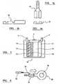
- When undertaking AC impedance measurement of electrochemical cells, the cell may be perturbed by injecting or drawing a current in an oscillating pattern or frequency, through the cell. The example, in
Figure 1 shows measurement apparatus 3 incorporating atransistor 1 to "short" the cell 2 in a current controlled manner. - One of the problems encountered when using this method is that, due to the very low impedances of the cells 2, the values of voltage response measured can be very small or minute.
- In this case, measurement of the voltage response cannot be undertaken using the same connector to the cell/battery as the one that carries the test current, since the test current, due to the connection resistance, will create a voltage drop across the connection and this will be measured by the sense electrode in addition to the cell voltage response.
- This connection resistance can be higher that the internal impedance of the cell and therefore the cell voltage response measurement will be distorted.
- If, for example, the cell impedance is 200 micro-Ohms and the connection resistance in the order of 1 milli-Ohm, any change in the cell impedance will be reduced, as a function of the total measurement, by 5:1. This will significantly reduce the ability of the measurement system 3 to detect key changes in cell impedance.
- It is therefore necessary to connect the current and sense leads using two
different connectors 4, 5, each of which must contact thecell termination post Figure 2 . - Most batteries for standby use are manufactured with contacts, for example, with 6 to 12 mm studs, or lugs through which a bolt may be fitted, for connection of the load carrying cables/straps to the battery posts.
- Standard ring-tab washers, sometimes called
spade terminal washers 20, or LUCARconnectors 20 can be procured for this type of connection as shown inFigure 3 . - It is normal for continuous battery monitoring systems to be connected to these
tab washers 20, so that the cell or battery may be monitored for failure conditions. Theconnector 24, which connects the current and sense wires to these tab washers, is, for example, a push-fit type as shown inFigure 4 . - Furthermore, it is desirable to know the temperature of the cell 2 as accurately as possible, since many failure modes in service manifest raised cell temperature as a symptom.
- However, measuring the internal temperature of a battery 2 is difficult in the field; since the external temperature of the base, due to its insulating properties, may be several degrees higher than the internal temperature of the plates, etc.
- It would therefore be more effective to measure the post temperature or temperature of the
cell termination posts Figure 5 shows an example of the construction of a Valve Regulated Lead-Acid (VRLA)cell 18. It can be seen that theterminal post 6, 7 (lug) is in direct thermal contact with the positive andnegative plates cell 18 comprises positive and negative group bars, positive and negative plates, aspun glass separator 14 containing electrolyte and a gassing andchemical recombination space 15.- Other prior instruments have used temperature measuring devices in contact with the cell post, using dedicated wires or leads additional to the existing Kelvin leads. However, this may result in several (for example, three or four)
connectors 24 being attached to severalcorresponding washers 20 on each contact of the battery. This is not possible in certain circumstances and particularly when the cell termination posts 6, 7 are relatively small or where access to theposts - It is an aim of the present invention to overcome at least one problem associated with the prior art whether referred to herein or otherwise.
WO 99/54744 DE 35 32 044US 2003/0092308 discloses a Kelvin connector for coupling to a post of a battery.US 2003/124417 discloses a battery test module mounted to a battery housing of a storage battery and electrically coupled to the terminals of the battery through Kelvin connections. A temperature sensor may be thermally coupled to the battery through an additional connector.- According to a first aspect of the present invention there is provided battery measuring apparatus comprising temperature sensing means and electrical measuring means wherein the apparatus comprise a first connection means which is arranged, in use, to connect both the temperature sensing means and the electrical measuring means to a first contact of the battery and the apparatus comprises a second connection means which is arranged, in use, to connect the electrical measuring means to a second contact of the battery.
- Preferably the first connection means comprise a first Kelvin connector. Preferably the second connection means comprises a second Kelvin connector.
- Preferably the temperature sensing means is connected using a lead of the electrical testing means.
- Preferably the temperature sensing means comprises temperature measuring means.
- Preferably the electrical measuring means is arranged to measure an electrical parameter of the battery. The electrical measuring means may measure the impedance and/or current and/or voltage of the battery.
- Preferably the first connection means comprises a single ended connector.
- The first connection means may comprise a first connector and a second connector each relating to a respective first connection lead and a second connection lead. The first connector may comprise a first push fit connector and the second connector may comprise a second push fit connector. The first push fit connector may be arranged, in use, to be secured to a first tab provided on a first contact of the battery and the second push fit connector may be arranged, in use, to be secured to a second tab provided on a first contact of the battery.
- The first tab may be provided on a first washer and the second tab may be provided on a second washer.
- The first tab and the second tab may be provided on a single washer.
- Preferably the first connection means comprise a single ended connector.
- The second connection means may comprise a first connector and a second connector each relating to a respective first connection lead and a second connection lead. The first connector may comprise a first push fit connector and the second connector may comprise a second push fit connector.
- The first push fit connector may be arranged, in use, to be secured to a first tab provided on a second contact of the battery and the second push fit connector may be arranged, in use, to be secured to a second tab provided on a second contact of the battery.
- The first tab may be provided on a first washer and the second tab may be provided on a second washer.
- The first tab and the second tab may be provided on a single washer.
- Preferably the first connection means comprise a single ended connector.
- Preferably the temperature sensing means is arranged, in use, to be in thermal contact (or communication, for example through conduction) with a first contact of the battery.
- Preferably the temperature sensing means is arranged to indicate or measure the internal temperature of the battery and preferably the core temperature of the battery.
- Preferably the temperature sensing means comprises a thermistor.
- Preferably the first connection means incorporates the thermistor.
- The first connection means may comprise a push fit connector. The connection means may comprise a first push fit connector and a second push fit connector.
- The second connection means may comprise a push fit connector. The second connection means may comprise a first push fit connector and a second push fit connector.
- The or each contact of the battery may comprise a washer and preferably comprises a tab washer. The or each contact of the battery may comprise a first tab washer and a second tab washer.
- Each (both) contact of the battery may comprise a first tab and a second tab in order for a first connector and a second connector to be secured to each (both) contact of the battery.
- Preferably the first connection means comprises a first connection lead and a second connection lead. The first connection lead may comprise a sense lead. The second connection lead may comprise a current lead.
- Preferably the thermistor is located in series along the first connection lead (the sense lead) of the first connection means.
- The first connection lead of the first connection means may be arranged, in use, to be connected to the first tab washer of a first contact of the battery and the second connection lead of the first connection means may be arranged, in use, to be connected to the second tab washer of a first contact of the battery.
- The first connection lead of the second connection means may be arranged, in use, to be connected to the first tab washer of a second contact of the battery and the second connection lead of the second connection means may be arranged, in use, to be connected to the second tab washer of a second contact of the battery.
- Preferably the second connection means comprises a first connection lead and a second connection lead.
- The first connection lead may comprise a sense lead. The second connection lead may comprise a current lead.
- Preferably the or each current lead applies a current to the respective contact of the battery.
- The second connection means may incorporate second temperature sensing means. The second temperature sensing means may comprise a second thermistor.
- Preferably the second thermistor locates in series along the first connection lead (the sense lead) of the second connection means.
- The battery measuring apparatus may be arranged to continuously measure an electrical parameter or characteristic of the battery and may be arranged to continuously sense and/or measure the temperature of the battery.
- According to a second aspect of the present invention there is provided an assembly comprising battery measuring apparatus and a battery, the battery measuring apparatus comprising temperature sensing means and electrical measuring means wherein the apparatus comprise a first connection means which is arranged, in use, to connect both the temperature sensing means and the electrical measuring means to a first contact of the battery and the apparatus comprises a second connection means which is arranged, in use, to connect the electrical measuring means to a second contact of the battery.
- The battery may comprise a cell or may comprise a monobloc.
- According to a third aspect of the present invention there is provided a method of measuring the temperature of a battery comprising securing electrical measuring apparatus to a contact of the battery and measuring the temperature of the battery and wherein the measuring apparatus comprises temperature sensing means and electrical measuring means.
- Preferably the method simultaneously measures the temperature and an electrical parameter or characteristic of the battery. The method may comprise measuring the impedance and/or current and/or voltage of the battery.
- Preferably the method comprises locating a temperature sensor of the temperature sensing means in thermal communication with the battery and more preferably in thermal communication within an internal part of the battery.
- The method may comprise securing a first connector to a first contact of the battery and may comprise securing a second connector to a second contact of the battery.
- The method may comprise securing a first connector and a second connector to a first contact of the battery and may comprise securing a third connector and a fourth connector to a second contact of the battery.
- The method may comprise connecting only two leads to a first contact of the battery and only two leads to a second contact of the battery in order to measure both the temperature of the battery and en electrical measurement of the battery.
- According to a fourth aspect of the present invention there is provided a Kelvin connector comprising temperature sensing means, the Kelvin connector comprising a sense lead and a current lead and connection means to connect the Kelvin connector to a contact of a battery wherein the temperature sensing means is connected along a lead of the Kelvin connector.
- Preferably, when the Kelvin connector is connected to the battery contact, the temperature sensing means is arranged to measure the temperature of the battery and more preferably indicate or measure the internal temperature of the battery.
- The temperature sensing means may comprises a thermistor.
- Preferably the thermistor is connected to the sense lead. Preferably the thermistor is connected in series along the sense lead.
- According to a fifth aspect of the present invention there is provided an assembly comprising a Kelvin connector and a battery, the Kelvin connector comprising temperature sensing means, the Kelvin connector further comprising a sense lead and a current lead and connection means to connect the Kelvin connector to a contact of a battery wherein the temperature sensing means is connected along a lead of the Kelvin connector.
- According to a sixth aspect of the present invention there is provided a method of measuring the temperature of a battery comprising securing a Kelvin connector to a contact of the battery wherein the Kelvin connector includes temperature sensing means.
- Preferably the temperature sensing means is located internally in the Kelvin connector.
- Preferably the temperature sensing means is connected using a lead of the Kelvin connector.
- Preferably the method comprises thermally connecting the temperature sensing means to a contact of the battery.
- The present invention will now be described, by way of example only, with reference to the drawings that follow, in which:
Figure 1 is a schematic diagram of prior art electrical measuring apparatus.Figure 2 is a schematic diagram of prior art electrical testing apparatus.Figure 3 is a plan view of an embodiment of a washer.Figure 4a is a plan view of a connector.Figure 4b is a side view of a connector.Figure 4c is a front view of a connector.Figure 5 is a schematic cross-section of a battery.Figure 6 is a plan view of a part of a preferred embodiment of a Kelvin connector including a temperature sensor.Figure 7 is a side view of a part of a preferred embodiment of a Kelvin connector including a temperature sensor.Figure 8 is a schematic diagram of a part of preferred embodiment of a Kelvin connector including a temperature sensor.Figure 9 is a schematic diagram of a preferred embodiment of combined electrical measuring and temperature sensing apparatus.Figure 10 is a schematic diagram of another embodiment of combined electrical measuring and temperature sensing apparatus.Figure 11 is a schematic view of an embodiment of part of first connection means of battery measuring apparatus.Figure 12 is a schematic view of an alternative embodiment of a washer.- During alternating current (AC) impedance measurement of electrochemical cells, the cell may be effected and, in particular, may be perturbed by applying (or injecting) or drawing a current in an oscillating pattern or frequency through the battery. As shown in
Figure 1 , a test instrument or system, uses a transistor to "short" the cell in a current controlled manner. The test instrument comprises a first connector which connects to a first terminal of an electrochemical cell and a second connector which connects to a second terminal. The term "battery" is interpreted and used to include all references to cells, batteries and monoblocs etc. - In many cases it would be inconvenient to utilise additional wires to connect a temperature sensitive device to the post, since this would necessitate having a separate connector at both the battery and the measuring device/instrument.
- Briefly, as shown in
Figure 9 , the present invention comprises combinedelectrical measuring apparatus 17 and temperature sensing apparatus wherein the number of connections required to eachcontract battery 18 which may be useful in monitoring the health of the battery. Prior art apparatus measures the temperature of the outside of the battery. However, the outside of the case will be at a lower temperature than the core because of the thermal insulation properties of the case material. The outside temperature becomes an equilibrium between the core temperature and the ambient temperature. Furthermore, the case material is likely to introduce time delays before an equilibrium is reached and the measurements can be made. - The apparatus comprises first connection means to connect to the
first contact 30 of thebattery 18 and second connection means to connect to thesecond contact 31 of thebattery 18. Each connection means comprises afirst lead second lead battery 18. Theapparatus 17 includes temperature sensing means, and in particular athermistor 36, which connects in series with onelead 32 of the connecting means in order for the temperature of thebattery 18 to also be measured. Accordingly, the present invention does not require the temperature sensor to be independently connected to thebattery 18. The present invention only requires four measurement leads 32, 33, 34, 35 together with two or four associated connectors as will be described in more detail. - More particularly, the present invention comprises impedance measurement means and temperature sensing means in order to measure both the temperature and impedance of a
battery 18 or cell, monobloc etc. Theapparatus 17 includes a first connection means in the form of a first Kelvin connector and a second connection means in the form of a second Kelvin connector. Theapparatus 17 does not include any further leads or connectors. As previously mentioned, prior art apparatus needs leads for connecting a temperature sensor and separate leads for connecting the electrical test apparatus to each post or terminal 30, 32 of abattery 18. - As shown in
Figure 6 andFigure 7 , the first connection means comprises a first push fit connector 24 (as shown inFigures 4a, 4b and 4c ) in order to be simply and quickly connected to a tab 22 located on afirst terminal 30 of thebattery 18. The pushfit connector 24 comprises a channel into which a lug or tab 22 of thetab washer 20 inserts in order to provide both a good electrical and thermal connection between the Kelvin connector and the post or terminal 30. The connector is arranged to secure thesense lead 32 to thecontact 30 of thetab washer 20 located between afirst nut 23 and asecond nut 21 which are located on a threaded shaft or part of thecontact 30. As can be seen fromFigure 7 , there is little room or space for numerous washers to be individually secured to thecontact 30. - The first connection means also comprises a second push
fit connector 24 in order to simply and quickly connect asecond lead 34 of the Kelvin connector to thefirst terminal 30 of the battery 18.Accordingly, the first terminal of thebattery 18 has a first tab washer and a second tab washer located thereon. - The first push
fit connector 24 is connected by a wire, or a section oflead 32, to temperature sensing means in the form of athermistor 36. Thethermistor 36 is connected in series with the connectinglead 32, as shown inFigure 8 andFigure 9 . - The second Kelvin connector is identical to the first Kelvin connector apart from the thermistor which is only provided on the first Kelvin connector.
- As shown in
Figure 7 , only a single connection is required at the battery post or terminal 30, 32 in order for both the temperature and impedance of thebattery 17 to be measured. It is appreciated that this single connection may comprise afirst connector 24 and asecond connector 24. In prior art apparatus, any temperature sensor required separate leads in order for the temperature sensor to be independently connected to the battery post or terminal 30, 32. This may require the use of three tab washers on a single terminal. These three separate connectors to a single terminal can be manually difficult to achieve, especially in relatively confined areas, and also may result in poor connection being made which may lead to measurement errors or inaccuracies. - As shown in
Figure 8 andFigure 9 , the first Kelvin connector includes a connecting lead comprising acurrent lead 33 and asense lead 32. Similarly, the second Kelvin connector includes a connecting lead comprising acurrent lead 35 and asense lead 34. Accordingly, the apparatus comprises four wire Kelvin testing apparatus. Thethermistor 36 is arranged in series with thesense lead 32 of the first Kelvin connector. Since thecurrent lead 33 and thesense lead 32 effectively form a short circuit at thepost 30. the resistance of thethermistor 36 can be calculated. The temperature sensing means comprises calculating means which measures the current induced in thesense lead 32 and the voltage drop across thethermistor 36. Figure 6 shows an example of a mechanical connection of a temperature dependent resistor, orthermistor 36, with thethermistor 36 in thermal connection with the push-fit connector 24 and in series electrical connection with thesense lead 32.- Similarly,
Figure 7 shows how thisconnector 24 would attach to thebattery post 30, in this case a bolt, perpendicular to the battery case 40, bringing thethermistor 36 into thermal connection with thepost 30 itself. - The current carrying lead attaches to another tab washer (not shown) on the
same post 30. - In the above illustration the ends of both leads 32 and 33 (34 and 35) of the positive (or negative) Kelvin connection are now effectively shortened by the
post 30, (31)/washer 20 junction, via thethermistor 36. Figure 8 shows how in the present invention the two Kelvin leads may now be used to measure the temperature of thebattery 18 and an electrical parameter of the battery, via theposts - As shown in
Figure 8 , atransistor 52 is used to draw a current from thebattery 18 through thethermistor 36 in thesense lead 32 to ground (battery negative). For the purpose of calculation, this current may be measured across the current limitingresistor 50, or assumed as a constant, since the measured temperature may be calibrated at manufacture. - The potential difference across the
thermistor 36 via the existing current leads 33 and sense leads 32 will be measured by the Analogue to Digital Converter (ADC) 56 and may be stored for calculation purposes in themicroprocessor 58. - Since the current carrying
Kelvin lead 33 and the signal sensing Kelvin lead 32 are effectively a short circuit at thebattery post 30, the resistance of thethermistor 36 may be calculated within theprocessor 58 from the current induced in thesense lead 32 by thetransistor 52 and the voltage drop across thethermistor 36. - The voltage drop across
thermistor 36 will vary directly in accordance with the temperature of thepost 30. - In the present invention, the two
wires battery 18, without any additional connections or wiring external to the measuring instrument or system. - The present invention however uses only the two existing Kelvin connectors each having the two usual leads themselves, and not a third or more dedicated lead(s) to acquire the post temperature.
- As shown in
Figure 10 , in an alternative embodiment theapparatus 17 may comprise afirst thermistor 36 in the first Kelvin connection and asecond thermistor 37 in the second Kelvin connection. - As shown in
Figure 11 , the first connection means may comprise a single pushfit connector 70 which is arranged to be secured to asingle spade tab 76 provided on acontact 30 of thebattery 18. The single pushfit connector 70 provides a first connecting (conducting)portion 72 or surface associated with thesense lead 32 and a second connecting (conducting)portion 73 or surface associated with thecurrent lead 33. Again, athermistor 36 is provided in series along thesense lead 32. Thetab 76 may be attached to thepost 30 or may be provided on a tab washer. In this embodiment, only a single endedconnector 70 is required to be secured to eachcontact battery 18. The second connection means may be the same as the first connection means apart from the thermistor. - As shown in
Figure 12 , a tab washer 89 may comprise afirst tab 82 and asecond tab 84 in order for both the first (push fit) connector and the second (push fit) connector of the or each Kelvin connector to be secured torespective contact 30 of thebattery 18. The use of a single washer reduces the space required along thecontact 30 of thebattery 18 since in some situations it may be difficult for two or more separate washers to be secured to asingle contact contact Figure 12 , the or each connectingnut washer 80 to the contact 30 (post) of thebattery 18 is arranged to form a connection 86 (i.e. an overlapping portion) over the separating portion between thefirst tab 82 and thesecond tab 84. This is required to provide an electrical communication from thefirst tab 82 and thesecond tab 84 rather than solely a direct electrical communication from thefirst tab 82 to thesecond tab 84.
Claims (18)
- Battery measuring apparatus (17) comprising temperature sensing means and electrical measuring means wherein the apparatus comprise a first connection means which is arranged, in use, to connect both the temperature sensing means and the electrical measuring means to a first contact (30) of the battery (18) and the apparatus comprises a second connection means which is arranged, in use, to connect the electrical measuring means to a second contact (31) of the battery (18),characterised in that the first connection means comprises a first Kelvin connector.
- Battery measuring apparatus according to claim 1 in which the second connection means comprises a second Kelvin connector.
- Battery measuring apparatus according to any preceding claim in which the temperature sensing means is connected using a lead of the electrical testing means.
- Battery measuring apparatus according to any preceding claim in which the electrical measuring means is arranged to measure an electrical parameter of the battery.
- Battery measuring apparatus according to claim 2 in which the first Kelvin connector comprises a first push fit connector (24, 70) and the second Kelvin connector comprises a second push fit connector.
- Battery measuring apparatus according to claim 5 in which the first push fit connector (24) is arranged, in use, to be secured to a first tab (82) provided on a first contact (30) of the battery (18) and the second push fit connector (24) is arranged, in use, to be secured to a second tab (84) provided on a first contact of the battery.
- Battery measuring apparatus according to claim 2 in which the first Kelvin connector comprises a first push fit connector (24, 70) and the second Kelvin connector comprises a second push fit connector (24, 70).
- Battery measuring apparatus according to claim 7 in which the first push fit connector (24) is arranged, in use, to be secured to a first tab (82) provided on a second contact (31) of the battery and the second push fit connector (24) is arranged, in use, to be secured to a second tab (84) provided on a second contact (31) of the battery.
- Battery measuring apparatus according to any preceding claim in which the temperature sensing means is arranged, in use, to be in thermal contact (or communication, for example through conduction) with a first contact of the battery.
- Battery measuring apparatus according to any preceding claim in which the temperature sensing means is arranged to indicate or measure the core temperature of the battery.
- Battery measuring apparatus according to any preceding claim in which the temperature sensing means comprises a thermistor (36).
- Battery measuring apparatus according to any preceding claim in which the battery measuring apparatus is arranged to continuously measure an electrical parameter or characteristic of the battery and is arranged to continuously sense and/or measure the temperature of the battery.
- Battery measuring apparatus according to any preceding claim wherein the first Kelvin connector comprises a sense lead (32) and a current lead (33) and wherein the temperature sensing means is connected along a lead (32, 33) of the first Kelvin connector.
- An assembly comprising a battery measuring apparatus according to any preceding claim and a battery.
- A method of measuring the temperature of a battery (18) comprising securing a first Kelvin connector of an electrical measuring apparatus (17) to a first contact (30) of the battery (18) and securing a second connector to a second contact (31) of the battery (18) and measuring the temperature of the battery and wherein the measuring apparatus comprises temperature sensing means and electrical measuring means,characterised in that the first Kelvin connector connects both the temperature sensing means and the electrical measuring means to the first contact of the battery.
- A method according to claim 15 in which the method simultaneously measures the temperature and an electrical parameter or characteristic of the battery.
- A method according to claim 15 or claim 16 in which the method comprises measuring the impedance and/or current and/or voltage of the battery.
- A method according to any one of claims 15 to 17 in which the method comprises connecting only two leads (32, 33) to the first contact (30) of the battery and only two leads (34, 35) to the second contact (31) of the battery in order to measure both the temperature of the battery and en electrical measurement of the battery.
Applications Claiming Priority (2)
| Application Number | Priority Date | Filing Date | Title |
|---|---|---|---|
| GB0424333AGB0424333D0 (en) | 2004-11-03 | 2004-11-03 | Kelvin connector including temperature sensor |
| PCT/GB2005/004209WO2006048625A1 (en) | 2004-11-03 | 2005-11-02 | Kelvin connector including temperature sensor |
Publications (2)
| Publication Number | Publication Date |
|---|---|
| EP1807710A1 EP1807710A1 (en) | 2007-07-18 |
| EP1807710B1true EP1807710B1 (en) | 2010-01-20 |
Family
ID=33523126
Family Applications (1)
| Application Number | Title | Priority Date | Filing Date |
|---|---|---|---|
| EP05807242ANot-in-forceEP1807710B1 (en) | 2004-11-03 | 2005-11-02 | Kelvin connector including temperature sensor |
Country Status (8)
| Country | Link |
|---|---|
| US (1) | US20080094068A1 (en) |
| EP (1) | EP1807710B1 (en) |
| JP (1) | JP2008519253A (en) |
| CN (1) | CN101048670A (en) |
| AT (1) | ATE456059T1 (en) |
| DE (1) | DE602005019080D1 (en) |
| GB (1) | GB0424333D0 (en) |
| WO (1) | WO2006048625A1 (en) |
Cited By (47)
| Publication number | Priority date | Publication date | Assignee | Title |
|---|---|---|---|---|
| US20110218747A1 (en)* | 2010-03-03 | 2011-09-08 | Bertness Kevin I | Monitor for front terminal batteries |
| US8493022B2 (en) | 1997-11-03 | 2013-07-23 | Midtronics, Inc. | Automotive vehicle electrical system diagnostic device |
| US8674711B2 (en) | 2003-09-05 | 2014-03-18 | Midtronics, Inc. | Method and apparatus for measuring a parameter of a vehicle electrical system |
| US8674654B2 (en) | 1997-11-03 | 2014-03-18 | Midtronics, Inc. | In-vehicle battery monitor |
| US8738309B2 (en) | 2010-09-30 | 2014-05-27 | Midtronics, Inc. | Battery pack maintenance for electric vehicles |
| US8754653B2 (en) | 1999-11-01 | 2014-06-17 | Midtronics, Inc. | Electronic battery tester |
| US8872516B2 (en) | 2000-03-27 | 2014-10-28 | Midtronics, Inc. | Electronic battery tester mounted in a vehicle |
| US8872517B2 (en) | 1996-07-29 | 2014-10-28 | Midtronics, Inc. | Electronic battery tester with battery age input |
| US8958998B2 (en) | 1997-11-03 | 2015-02-17 | Midtronics, Inc. | Electronic battery tester with network communication |
| US8963550B2 (en) | 2004-08-20 | 2015-02-24 | Midtronics, Inc. | System for automatically gathering battery information |
| US9018958B2 (en) | 2003-09-05 | 2015-04-28 | Midtronics, Inc. | Method and apparatus for measuring a parameter of a vehicle electrical system |
| US9052366B2 (en) | 2000-03-27 | 2015-06-09 | Midtronics, Inc. | Battery testers with secondary functionality |
| US9201120B2 (en) | 2010-08-12 | 2015-12-01 | Midtronics, Inc. | Electronic battery tester for testing storage battery |
| US9229062B2 (en) | 2010-05-27 | 2016-01-05 | Midtronics, Inc. | Electronic storage battery diagnostic system |
| US9244100B2 (en) | 2013-03-15 | 2016-01-26 | Midtronics, Inc. | Current clamp with jaw closure detection |
| US9255955B2 (en) | 2003-09-05 | 2016-02-09 | Midtronics, Inc. | Method and apparatus for measuring a parameter of a vehicle electrical system |
| US9274157B2 (en) | 2007-07-17 | 2016-03-01 | Midtronics, Inc. | Battery tester for electric vehicle |
| US9312575B2 (en) | 2013-05-16 | 2016-04-12 | Midtronics, Inc. | Battery testing system and method |
| US9335362B2 (en) | 2007-07-17 | 2016-05-10 | Midtronics, Inc. | Battery tester for electric vehicle |
| US9419311B2 (en) | 2010-06-18 | 2016-08-16 | Midtronics, Inc. | Battery maintenance device with thermal buffer |
| US9496720B2 (en) | 2004-08-20 | 2016-11-15 | Midtronics, Inc. | System for automatically gathering battery information |
| US9588185B2 (en) | 2010-02-25 | 2017-03-07 | Keith S. Champlin | Method and apparatus for detecting cell deterioration in an electrochemical cell or battery |
| US9851411B2 (en) | 2012-06-28 | 2017-12-26 | Keith S. Champlin | Suppressing HF cable oscillations during dynamic measurements of cells and batteries |
| US9923289B2 (en) | 2014-01-16 | 2018-03-20 | Midtronics, Inc. | Battery clamp with endoskeleton design |
| US9966676B2 (en) | 2015-09-28 | 2018-05-08 | Midtronics, Inc. | Kelvin connector adapter for storage battery |
| US10046649B2 (en) | 2012-06-28 | 2018-08-14 | Midtronics, Inc. | Hybrid and electric vehicle battery pack maintenance device |
| US10222397B2 (en) | 2014-09-26 | 2019-03-05 | Midtronics, Inc. | Cable connector for electronic battery tester |
| US10317468B2 (en) | 2015-01-26 | 2019-06-11 | Midtronics, Inc. | Alternator tester |
| US10429449B2 (en) | 2011-11-10 | 2019-10-01 | Midtronics, Inc. | Battery pack tester |
| US10473555B2 (en) | 2014-07-14 | 2019-11-12 | Midtronics, Inc. | Automotive maintenance system |
| US10608353B2 (en) | 2016-06-28 | 2020-03-31 | Midtronics, Inc. | Battery clamp |
| US10843574B2 (en) | 2013-12-12 | 2020-11-24 | Midtronics, Inc. | Calibration and programming of in-vehicle battery sensors |
| US11054480B2 (en) | 2016-10-25 | 2021-07-06 | Midtronics, Inc. | Electrical load for electronic battery tester and electronic battery tester including such electrical load |
| US11325479B2 (en) | 2012-06-28 | 2022-05-10 | Midtronics, Inc. | Hybrid and electric vehicle battery maintenance device |
| US11474153B2 (en) | 2019-11-12 | 2022-10-18 | Midtronics, Inc. | Battery pack maintenance system |
| US11486930B2 (en) | 2020-01-23 | 2022-11-01 | Midtronics, Inc. | Electronic battery tester with battery clamp storage holsters |
| US11513160B2 (en) | 2018-11-29 | 2022-11-29 | Midtronics, Inc. | Vehicle battery maintenance device |
| US11545839B2 (en) | 2019-11-05 | 2023-01-03 | Midtronics, Inc. | System for charging a series of connected batteries |
| US11566972B2 (en) | 2019-07-31 | 2023-01-31 | Midtronics, Inc. | Tire tread gauge using visual indicator |
| US11650259B2 (en) | 2010-06-03 | 2023-05-16 | Midtronics, Inc. | Battery pack maintenance for electric vehicle |
| US11668779B2 (en) | 2019-11-11 | 2023-06-06 | Midtronics, Inc. | Hybrid and electric vehicle battery pack maintenance device |
| US11740294B2 (en) | 2010-06-03 | 2023-08-29 | Midtronics, Inc. | High use battery pack maintenance |
| US11973202B2 (en) | 2019-12-31 | 2024-04-30 | Midtronics, Inc. | Intelligent module interface for battery maintenance device |
| US12237482B2 (en) | 2019-12-31 | 2025-02-25 | Midtronics, Inc. | Intelligent module interface for battery maintenance device |
| US12320857B2 (en) | 2016-10-25 | 2025-06-03 | Midtronics, Inc. | Electrical load for electronic battery tester and electronic battery tester including such electrical load |
| US12330513B2 (en) | 2022-02-14 | 2025-06-17 | Midtronics, Inc. | Battery maintenance device with high voltage connector |
| US12392833B2 (en) | 2022-05-09 | 2025-08-19 | Midtronics, Inc. | Electronic battery tester |
Families Citing this family (19)
| Publication number | Priority date | Publication date | Assignee | Title |
|---|---|---|---|---|
| US8436619B2 (en) | 2004-08-20 | 2013-05-07 | Midtronics, Inc. | Integrated tag reader and environment sensor |
| JP4836909B2 (en)* | 2007-09-26 | 2011-12-14 | 古河電池株式会社 | Terminal for measurement |
| CN102308432B (en)* | 2010-04-28 | 2013-12-18 | 丰田自动车株式会社 | Cell temperature measurement device, cell temperature measurement method and cell production method |
| DE102010026435B4 (en)* | 2010-07-08 | 2023-01-26 | Vitesco Technologies Germany Gmbh | Device for classifying an electrical contact between two connection elements |
| CN102163808A (en)* | 2011-01-28 | 2011-08-24 | 南京大全电气有限公司 | Small control bus of low-voltage cabinet top |
| CN102288791B (en)* | 2011-05-10 | 2013-06-19 | 无锡市汇博普纳电子有限公司 | Wire frame and gold finger structure for Kelvin testing and sorting |
| JP2013195145A (en)* | 2012-03-16 | 2013-09-30 | Furukawa Battery Co Ltd:The | Internal resistance measuring terminal |
| DE202013100811U1 (en) | 2013-02-25 | 2014-06-02 | Rp-Technik E.K. | Power supply device with battery monitoring |
| DE102014102366B4 (en) | 2013-02-25 | 2021-03-04 | Rp-Technik Gmbh | Energy supply device with battery monitoring and battery monitoring process |
| KR101720614B1 (en)* | 2013-08-30 | 2017-03-28 | 삼성에스디아이 주식회사 | Battery pack |
| EP2911269B1 (en) | 2014-02-24 | 2017-07-05 | RP-Technik GmbH | Power supply device with battery monitoring and battery monitoring method |
| US10023112B2 (en)* | 2015-04-23 | 2018-07-17 | Ford Global Technologies, Llc | Battery joint monitoring method and assembly |
| CN106640047A (en)* | 2015-10-30 | 2017-05-10 | 中石化石油工程技术服务有限公司 | Underground integrated measurement connector |
| TWI622780B (en)* | 2016-11-28 | 2018-05-01 | Dhc Specialty Corp | Asymmetric battery detection device |
| US10177542B2 (en)* | 2017-02-10 | 2019-01-08 | Hamilton Sundstrand Corporation | Contactor health monitoring systems and methods |
| DE102017209182A1 (en) | 2017-05-31 | 2018-12-06 | Bayerische Motoren Werke Aktiengesellschaft | Method and device for determining an operating temperature, operating method for a battery cell, control unit for a battery cell and working device |
| US10516221B1 (en)* | 2018-08-24 | 2019-12-24 | Franklin Grid Solutions, Llc | Kelvin connection mounting terminal |
| EP3786905A1 (en)* | 2019-09-02 | 2021-03-03 | Valeo Comfort and Driving Assistance | Vehicle telecommunicating unit and backup battery for vehicle telematics system |
| CN113777536B (en)* | 2021-11-10 | 2022-01-21 | 杭州维纳安可医疗科技有限责任公司 | Testing jig, testing device and testing method for electrode patches |
Family Cites Families (6)
| Publication number | Priority date | Publication date | Assignee | Title |
|---|---|---|---|---|
| DE3532044A1 (en)* | 1985-09-09 | 1987-03-19 | Vdo Schindling | POLE CLAMP |
| US6850037B2 (en)* | 1997-11-03 | 2005-02-01 | Midtronics, Inc. | In-vehicle battery monitor |
| EP0990167B1 (en)* | 1998-04-17 | 2006-06-07 | AK Systemtechnik AG | Battery measuring terminal |
| US7039533B2 (en)* | 1999-04-08 | 2006-05-02 | Midtronics, Inc. | Battery test module |
| US6257911B1 (en)* | 1999-11-10 | 2001-07-10 | Frank S. Shelby | Low insertion force connector with wipe |
| US7198510B2 (en)* | 2001-11-14 | 2007-04-03 | Midtronics, Inc. | Kelvin connector for a battery post |
- 2004
- 2004-11-03GBGB0424333Apatent/GB0424333D0/ennot_activeCeased
- 2005
- 2005-11-02EPEP05807242Apatent/EP1807710B1/ennot_activeNot-in-force
- 2005-11-02WOPCT/GB2005/004209patent/WO2006048625A1/enactiveApplication Filing
- 2005-11-02ATAT05807242Tpatent/ATE456059T1/ennot_activeIP Right Cessation
- 2005-11-02JPJP2007538520Apatent/JP2008519253A/ennot_activeWithdrawn
- 2005-11-02USUS11/666,036patent/US20080094068A1/ennot_activeAbandoned
- 2005-11-02CNCNA2005800373059Apatent/CN101048670A/enactivePending
- 2005-11-02DEDE602005019080Tpatent/DE602005019080D1/enactiveActive
Cited By (53)
| Publication number | Priority date | Publication date | Assignee | Title |
|---|---|---|---|---|
| US8872517B2 (en) | 1996-07-29 | 2014-10-28 | Midtronics, Inc. | Electronic battery tester with battery age input |
| US8674654B2 (en) | 1997-11-03 | 2014-03-18 | Midtronics, Inc. | In-vehicle battery monitor |
| US8958998B2 (en) | 1997-11-03 | 2015-02-17 | Midtronics, Inc. | Electronic battery tester with network communication |
| US8493022B2 (en) | 1997-11-03 | 2013-07-23 | Midtronics, Inc. | Automotive vehicle electrical system diagnostic device |
| US8754653B2 (en) | 1999-11-01 | 2014-06-17 | Midtronics, Inc. | Electronic battery tester |
| US8872516B2 (en) | 2000-03-27 | 2014-10-28 | Midtronics, Inc. | Electronic battery tester mounted in a vehicle |
| US9052366B2 (en) | 2000-03-27 | 2015-06-09 | Midtronics, Inc. | Battery testers with secondary functionality |
| US9255955B2 (en) | 2003-09-05 | 2016-02-09 | Midtronics, Inc. | Method and apparatus for measuring a parameter of a vehicle electrical system |
| US8674711B2 (en) | 2003-09-05 | 2014-03-18 | Midtronics, Inc. | Method and apparatus for measuring a parameter of a vehicle electrical system |
| US9018958B2 (en) | 2003-09-05 | 2015-04-28 | Midtronics, Inc. | Method and apparatus for measuring a parameter of a vehicle electrical system |
| US9496720B2 (en) | 2004-08-20 | 2016-11-15 | Midtronics, Inc. | System for automatically gathering battery information |
| US8963550B2 (en) | 2004-08-20 | 2015-02-24 | Midtronics, Inc. | System for automatically gathering battery information |
| US9335362B2 (en) | 2007-07-17 | 2016-05-10 | Midtronics, Inc. | Battery tester for electric vehicle |
| US9274157B2 (en) | 2007-07-17 | 2016-03-01 | Midtronics, Inc. | Battery tester for electric vehicle |
| US9588185B2 (en) | 2010-02-25 | 2017-03-07 | Keith S. Champlin | Method and apparatus for detecting cell deterioration in an electrochemical cell or battery |
| US20110218747A1 (en)* | 2010-03-03 | 2011-09-08 | Bertness Kevin I | Monitor for front terminal batteries |
| CN102804478B (en)* | 2010-03-03 | 2015-12-16 | 密特电子公司 | For the watch-dog of front terminals battery |
| US9425487B2 (en)* | 2010-03-03 | 2016-08-23 | Midtronics, Inc. | Monitor for front terminal batteries |
| CN102804478A (en)* | 2010-03-03 | 2012-11-28 | 密特电子公司 | Monitor for front terminal batteries |
| US9229062B2 (en) | 2010-05-27 | 2016-01-05 | Midtronics, Inc. | Electronic storage battery diagnostic system |
| US11650259B2 (en) | 2010-06-03 | 2023-05-16 | Midtronics, Inc. | Battery pack maintenance for electric vehicle |
| US11740294B2 (en) | 2010-06-03 | 2023-08-29 | Midtronics, Inc. | High use battery pack maintenance |
| US12196813B2 (en) | 2010-06-03 | 2025-01-14 | Midtronics, Inc. | High use battery pack maintenance |
| US9419311B2 (en) | 2010-06-18 | 2016-08-16 | Midtronics, Inc. | Battery maintenance device with thermal buffer |
| US9201120B2 (en) | 2010-08-12 | 2015-12-01 | Midtronics, Inc. | Electronic battery tester for testing storage battery |
| US8738309B2 (en) | 2010-09-30 | 2014-05-27 | Midtronics, Inc. | Battery pack maintenance for electric vehicles |
| US10429449B2 (en) | 2011-11-10 | 2019-10-01 | Midtronics, Inc. | Battery pack tester |
| US9851411B2 (en) | 2012-06-28 | 2017-12-26 | Keith S. Champlin | Suppressing HF cable oscillations during dynamic measurements of cells and batteries |
| US11325479B2 (en) | 2012-06-28 | 2022-05-10 | Midtronics, Inc. | Hybrid and electric vehicle battery maintenance device |
| US10046649B2 (en) | 2012-06-28 | 2018-08-14 | Midtronics, Inc. | Hybrid and electric vehicle battery pack maintenance device |
| US11926224B2 (en) | 2012-06-28 | 2024-03-12 | Midtronics, Inc. | Hybrid and electric vehicle battery pack maintenance device |
| US11548404B2 (en) | 2012-06-28 | 2023-01-10 | Midtronics, Inc. | Hybrid and electric vehicle battery pack maintenance device |
| US9244100B2 (en) | 2013-03-15 | 2016-01-26 | Midtronics, Inc. | Current clamp with jaw closure detection |
| US9312575B2 (en) | 2013-05-16 | 2016-04-12 | Midtronics, Inc. | Battery testing system and method |
| US10843574B2 (en) | 2013-12-12 | 2020-11-24 | Midtronics, Inc. | Calibration and programming of in-vehicle battery sensors |
| US9923289B2 (en) | 2014-01-16 | 2018-03-20 | Midtronics, Inc. | Battery clamp with endoskeleton design |
| US10473555B2 (en) | 2014-07-14 | 2019-11-12 | Midtronics, Inc. | Automotive maintenance system |
| US10222397B2 (en) | 2014-09-26 | 2019-03-05 | Midtronics, Inc. | Cable connector for electronic battery tester |
| US10317468B2 (en) | 2015-01-26 | 2019-06-11 | Midtronics, Inc. | Alternator tester |
| US9966676B2 (en) | 2015-09-28 | 2018-05-08 | Midtronics, Inc. | Kelvin connector adapter for storage battery |
| US10608353B2 (en) | 2016-06-28 | 2020-03-31 | Midtronics, Inc. | Battery clamp |
| US12320857B2 (en) | 2016-10-25 | 2025-06-03 | Midtronics, Inc. | Electrical load for electronic battery tester and electronic battery tester including such electrical load |
| US11054480B2 (en) | 2016-10-25 | 2021-07-06 | Midtronics, Inc. | Electrical load for electronic battery tester and electronic battery tester including such electrical load |
| US11513160B2 (en) | 2018-11-29 | 2022-11-29 | Midtronics, Inc. | Vehicle battery maintenance device |
| US11566972B2 (en) | 2019-07-31 | 2023-01-31 | Midtronics, Inc. | Tire tread gauge using visual indicator |
| US11545839B2 (en) | 2019-11-05 | 2023-01-03 | Midtronics, Inc. | System for charging a series of connected batteries |
| US11668779B2 (en) | 2019-11-11 | 2023-06-06 | Midtronics, Inc. | Hybrid and electric vehicle battery pack maintenance device |
| US11474153B2 (en) | 2019-11-12 | 2022-10-18 | Midtronics, Inc. | Battery pack maintenance system |
| US11973202B2 (en) | 2019-12-31 | 2024-04-30 | Midtronics, Inc. | Intelligent module interface for battery maintenance device |
| US12237482B2 (en) | 2019-12-31 | 2025-02-25 | Midtronics, Inc. | Intelligent module interface for battery maintenance device |
| US11486930B2 (en) | 2020-01-23 | 2022-11-01 | Midtronics, Inc. | Electronic battery tester with battery clamp storage holsters |
| US12330513B2 (en) | 2022-02-14 | 2025-06-17 | Midtronics, Inc. | Battery maintenance device with high voltage connector |
| US12392833B2 (en) | 2022-05-09 | 2025-08-19 | Midtronics, Inc. | Electronic battery tester |
Also Published As
| Publication number | Publication date |
|---|---|
| JP2008519253A (en) | 2008-06-05 |
| EP1807710A1 (en) | 2007-07-18 |
| US20080094068A1 (en) | 2008-04-24 |
| GB0424333D0 (en) | 2004-12-08 |
| CN101048670A (en) | 2007-10-03 |
| DE602005019080D1 (en) | 2010-03-11 |
| WO2006048625A1 (en) | 2006-05-11 |
| ATE456059T1 (en) | 2010-02-15 |
Similar Documents
| Publication | Publication Date | Title |
|---|---|---|
| EP1807710B1 (en) | Kelvin connector including temperature sensor | |
| EP1247304B1 (en) | Shunt resistance device for monitoring battery state of charge | |
| EP2256900B1 (en) | Terminal Assembly for a Battery | |
| US7598699B2 (en) | Replaceable clamp for electronic battery tester | |
| US20120119745A1 (en) | Battery monitor with correction for internal ohmic measurements of battery cells in parallel connected battery strings | |
| KR20150018412A (en) | Battery pack | |
| EP2257823B1 (en) | Current measurement apparatus with shunt resistor and heat sink | |
| CN112858933B (en) | Sensor systems for battery modules | |
| US10066999B2 (en) | System and method for monitoring exceptional watt hour meter terminal temperature | |
| KR101802926B1 (en) | Battery having Sensing Assembly Structure for Processing Signal of Cell | |
| EP3346524A1 (en) | Battery module with thermocouple unit | |
| US20110279124A1 (en) | Float current monitor | |
| KR101080127B1 (en) | Precise Detector of Charge and Discharge Conditions | |
| CN113167658B (en) | Sensor, electrical energy storage device and apparatus | |
| EP3823076B1 (en) | Sensor system for a battery module | |
| CN222215171U (en) | Protection board circuit and electronic equipment | |
| CN219417581U (en) | Shunt and battery system | |
| CN223180376U (en) | Wireless cell detection device and battery module | |
| US20250076384A1 (en) | Integrated current sensing device and battery pack including the same | |
| CN209460288U (en) | It is a kind of for connecting the measurement terminal of battery | |
| WO2024145591A9 (en) | Battery cell temperature measurement system | |
| CN117517984A (en) | Battery cell sampling device and battery module | |
| CN117517824A (en) | Device and method for measuring current carrying capacity of battery tab | |
| CN116298451A (en) | Current divider, current measurement method and battery system |
Legal Events
| Date | Code | Title | Description |
|---|---|---|---|
| PUAI | Public reference made under article 153(3) epc to a published international application that has entered the european phase | Free format text:ORIGINAL CODE: 0009012 | |
| 17P | Request for examination filed | Effective date:20070424 | |
| AK | Designated contracting states | Kind code of ref document:A1 Designated state(s):AT BE BG CH CY CZ DE DK EE ES FI FR GB GR HU IE IS IT LI LT LU LV MC NL PL PT RO SE SI SK TR | |
| 17Q | First examination report despatched | Effective date:20070904 | |
| DAX | Request for extension of the european patent (deleted) | ||
| GRAP | Despatch of communication of intention to grant a patent | Free format text:ORIGINAL CODE: EPIDOSNIGR1 | |
| GRAS | Grant fee paid | Free format text:ORIGINAL CODE: EPIDOSNIGR3 | |
| GRAA | (expected) grant | Free format text:ORIGINAL CODE: 0009210 | |
| AK | Designated contracting states | Kind code of ref document:B1 Designated state(s):AT BE BG CH CY CZ DE DK EE ES FI FR GB GR HU IE IS IT LI LT LU LV MC NL PL PT RO SE SI SK TR | |
| REG | Reference to a national code | Ref country code:GB Ref legal event code:FG4D | |
| REG | Reference to a national code | Ref country code:CH Ref legal event code:EP | |
| REG | Reference to a national code | Ref country code:IE Ref legal event code:FG4D | |
| REF | Corresponds to: | Ref document number:602005019080 Country of ref document:DE Date of ref document:20100311 Kind code of ref document:P | |
| REG | Reference to a national code | Ref country code:NL Ref legal event code:VDEP Effective date:20100120 | |
| LTIE | Lt: invalidation of european patent or patent extension | Effective date:20100120 | |
| PG25 | Lapsed in a contracting state [announced via postgrant information from national office to epo] | Ref country code:AT Free format text:LAPSE BECAUSE OF FAILURE TO SUBMIT A TRANSLATION OF THE DESCRIPTION OR TO PAY THE FEE WITHIN THE PRESCRIBED TIME-LIMIT Effective date:20100120 | |
| PG25 | Lapsed in a contracting state [announced via postgrant information from national office to epo] | Ref country code:ES Free format text:LAPSE BECAUSE OF FAILURE TO SUBMIT A TRANSLATION OF THE DESCRIPTION OR TO PAY THE FEE WITHIN THE PRESCRIBED TIME-LIMIT Effective date:20100501 Ref country code:IS Free format text:LAPSE BECAUSE OF FAILURE TO SUBMIT A TRANSLATION OF THE DESCRIPTION OR TO PAY THE FEE WITHIN THE PRESCRIBED TIME-LIMIT Effective date:20100520 Ref country code:PT Free format text:LAPSE BECAUSE OF FAILURE TO SUBMIT A TRANSLATION OF THE DESCRIPTION OR TO PAY THE FEE WITHIN THE PRESCRIBED TIME-LIMIT Effective date:20100520 Ref country code:NL Free format text:LAPSE BECAUSE OF FAILURE TO SUBMIT A TRANSLATION OF THE DESCRIPTION OR TO PAY THE FEE WITHIN THE PRESCRIBED TIME-LIMIT Effective date:20100120 Ref country code:LT Free format text:LAPSE BECAUSE OF FAILURE TO SUBMIT A TRANSLATION OF THE DESCRIPTION OR TO PAY THE FEE WITHIN THE PRESCRIBED TIME-LIMIT Effective date:20100120 | |
| PG25 | Lapsed in a contracting state [announced via postgrant information from national office to epo] | Ref country code:SI Free format text:LAPSE BECAUSE OF FAILURE TO SUBMIT A TRANSLATION OF THE DESCRIPTION OR TO PAY THE FEE WITHIN THE PRESCRIBED TIME-LIMIT Effective date:20100120 Ref country code:PL Free format text:LAPSE BECAUSE OF FAILURE TO SUBMIT A TRANSLATION OF THE DESCRIPTION OR TO PAY THE FEE WITHIN THE PRESCRIBED TIME-LIMIT Effective date:20100120 Ref country code:LV Free format text:LAPSE BECAUSE OF FAILURE TO SUBMIT A TRANSLATION OF THE DESCRIPTION OR TO PAY THE FEE WITHIN THE PRESCRIBED TIME-LIMIT Effective date:20100120 Ref country code:FI Free format text:LAPSE BECAUSE OF FAILURE TO SUBMIT A TRANSLATION OF THE DESCRIPTION OR TO PAY THE FEE WITHIN THE PRESCRIBED TIME-LIMIT Effective date:20100120 | |
| PG25 | Lapsed in a contracting state [announced via postgrant information from national office to epo] | Ref country code:GR Free format text:LAPSE BECAUSE OF FAILURE TO SUBMIT A TRANSLATION OF THE DESCRIPTION OR TO PAY THE FEE WITHIN THE PRESCRIBED TIME-LIMIT Effective date:20100421 Ref country code:SE Free format text:LAPSE BECAUSE OF FAILURE TO SUBMIT A TRANSLATION OF THE DESCRIPTION OR TO PAY THE FEE WITHIN THE PRESCRIBED TIME-LIMIT Effective date:20100120 Ref country code:RO Free format text:LAPSE BECAUSE OF FAILURE TO SUBMIT A TRANSLATION OF THE DESCRIPTION OR TO PAY THE FEE WITHIN THE PRESCRIBED TIME-LIMIT Effective date:20100120 Ref country code:EE Free format text:LAPSE BECAUSE OF FAILURE TO SUBMIT A TRANSLATION OF THE DESCRIPTION OR TO PAY THE FEE WITHIN THE PRESCRIBED TIME-LIMIT Effective date:20100120 Ref country code:CY Free format text:LAPSE BECAUSE OF FAILURE TO SUBMIT A TRANSLATION OF THE DESCRIPTION OR TO PAY THE FEE WITHIN THE PRESCRIBED TIME-LIMIT Effective date:20100120 Ref country code:BE Free format text:LAPSE BECAUSE OF FAILURE TO SUBMIT A TRANSLATION OF THE DESCRIPTION OR TO PAY THE FEE WITHIN THE PRESCRIBED TIME-LIMIT Effective date:20100120 | |
| PLBE | No opposition filed within time limit | Free format text:ORIGINAL CODE: 0009261 | |
| STAA | Information on the status of an ep patent application or granted ep patent | Free format text:STATUS: NO OPPOSITION FILED WITHIN TIME LIMIT | |
| PG25 | Lapsed in a contracting state [announced via postgrant information from national office to epo] | Ref country code:SK Free format text:LAPSE BECAUSE OF FAILURE TO SUBMIT A TRANSLATION OF THE DESCRIPTION OR TO PAY THE FEE WITHIN THE PRESCRIBED TIME-LIMIT Effective date:20100120 Ref country code:CZ Free format text:LAPSE BECAUSE OF FAILURE TO SUBMIT A TRANSLATION OF THE DESCRIPTION OR TO PAY THE FEE WITHIN THE PRESCRIBED TIME-LIMIT Effective date:20100120 Ref country code:BG Free format text:LAPSE BECAUSE OF FAILURE TO SUBMIT A TRANSLATION OF THE DESCRIPTION OR TO PAY THE FEE WITHIN THE PRESCRIBED TIME-LIMIT Effective date:20100420 | |
| 26N | No opposition filed | Effective date:20101021 | |
| PG25 | Lapsed in a contracting state [announced via postgrant information from national office to epo] | Ref country code:DK Free format text:LAPSE BECAUSE OF FAILURE TO SUBMIT A TRANSLATION OF THE DESCRIPTION OR TO PAY THE FEE WITHIN THE PRESCRIBED TIME-LIMIT Effective date:20100120 | |
| PG25 | Lapsed in a contracting state [announced via postgrant information from national office to epo] | Ref country code:IT Free format text:LAPSE BECAUSE OF FAILURE TO SUBMIT A TRANSLATION OF THE DESCRIPTION OR TO PAY THE FEE WITHIN THE PRESCRIBED TIME-LIMIT Effective date:20100120 | |
| PG25 | Lapsed in a contracting state [announced via postgrant information from national office to epo] | Ref country code:MC Free format text:LAPSE BECAUSE OF NON-PAYMENT OF DUE FEES Effective date:20101130 | |
| REG | Reference to a national code | Ref country code:CH Ref legal event code:PL | |
| GBPC | Gb: european patent ceased through non-payment of renewal fee | Effective date:20101102 | |
| PG25 | Lapsed in a contracting state [announced via postgrant information from national office to epo] | Ref country code:CH Free format text:LAPSE BECAUSE OF NON-PAYMENT OF DUE FEES Effective date:20101130 Ref country code:LI Free format text:LAPSE BECAUSE OF NON-PAYMENT OF DUE FEES Effective date:20101130 | |
| PG25 | Lapsed in a contracting state [announced via postgrant information from national office to epo] | Ref country code:IE Free format text:LAPSE BECAUSE OF NON-PAYMENT OF DUE FEES Effective date:20101102 | |
| PG25 | Lapsed in a contracting state [announced via postgrant information from national office to epo] | Ref country code:GB Free format text:LAPSE BECAUSE OF NON-PAYMENT OF DUE FEES Effective date:20101102 | |
| PG25 | Lapsed in a contracting state [announced via postgrant information from national office to epo] | Ref country code:HU Free format text:LAPSE BECAUSE OF FAILURE TO SUBMIT A TRANSLATION OF THE DESCRIPTION OR TO PAY THE FEE WITHIN THE PRESCRIBED TIME-LIMIT Effective date:20100721 Ref country code:LU Free format text:LAPSE BECAUSE OF NON-PAYMENT OF DUE FEES Effective date:20101102 | |
| PG25 | Lapsed in a contracting state [announced via postgrant information from national office to epo] | Ref country code:TR Free format text:LAPSE BECAUSE OF FAILURE TO SUBMIT A TRANSLATION OF THE DESCRIPTION OR TO PAY THE FEE WITHIN THE PRESCRIBED TIME-LIMIT Effective date:20100120 | |
| REG | Reference to a national code | Ref country code:FR Ref legal event code:PLFP Year of fee payment:11 | |
| REG | Reference to a national code | Ref country code:FR Ref legal event code:PLFP Year of fee payment:12 | |
| REG | Reference to a national code | Ref country code:FR Ref legal event code:PLFP Year of fee payment:13 | |
| PGFP | Annual fee paid to national office [announced via postgrant information from national office to epo] | Ref country code:DE Payment date:20191121 Year of fee payment:15 | |
| PGFP | Annual fee paid to national office [announced via postgrant information from national office to epo] | Ref country code:FR Payment date:20191120 Year of fee payment:15 | |
| REG | Reference to a national code | Ref country code:DE Ref legal event code:R119 Ref document number:602005019080 Country of ref document:DE | |
| PG25 | Lapsed in a contracting state [announced via postgrant information from national office to epo] | Ref country code:FR Free format text:LAPSE BECAUSE OF NON-PAYMENT OF DUE FEES Effective date:20201130 | |
| PG25 | Lapsed in a contracting state [announced via postgrant information from national office to epo] | Ref country code:DE Free format text:LAPSE BECAUSE OF NON-PAYMENT OF DUE FEES Effective date:20210601 |