EP1807304B1 - Method and device for enhancing the braking efficiency of an aircraft during the ground run thereof - Google Patents
Method and device for enhancing the braking efficiency of an aircraft during the ground run thereofDownload PDFInfo
- Publication number
- EP1807304B1 EP1807304B1EP05809326AEP05809326AEP1807304B1EP 1807304 B1EP1807304 B1EP 1807304B1EP 05809326 AEP05809326 AEP 05809326AEP 05809326 AEP05809326 AEP 05809326AEP 1807304 B1EP1807304 B1EP 1807304B1
- Authority
- EP
- European Patent Office
- Prior art keywords
- value
- aircraft
- elevators
- ground
- characteristic
- Prior art date
- Legal status (The legal status is an assumption and is not a legal conclusion. Google has not performed a legal analysis and makes no representation as to the accuracy of the status listed.)
- Expired - Lifetime
Links
Images


Classifications
- B—PERFORMING OPERATIONS; TRANSPORTING
- B64—AIRCRAFT; AVIATION; COSMONAUTICS
- B64C—AEROPLANES; HELICOPTERS
- B64C13/00—Control systems or transmitting systems for actuating flying-control surfaces, lift-increasing flaps, air brakes, or spoilers
- B64C13/02—Initiating means
- B64C13/16—Initiating means actuated automatically, e.g. responsive to gust detectors
- B—PERFORMING OPERATIONS; TRANSPORTING
- B64—AIRCRAFT; AVIATION; COSMONAUTICS
- B64C—AEROPLANES; HELICOPTERS
- B64C25/00—Alighting gear
- B64C25/32—Alighting gear characterised by elements which contact the ground or similar surface
- B64C25/42—Arrangement or adaptation of brakes
Definitions
- the present inventionrelates to a method and a device for improving the braking efficiency of an aircraft taxiing on the ground.
- EP-A-0 936 114describes a process according to the preamble of claim 1.
- the present inventionaims to overcome this disadvantage and to confer such an aircraft rolling on the ground braking efficiency always optimal.
- Said reference value for the vertical force applied by the ground on said nose gearcan be determined by calculation or by direct experimental measurement on said nose gear. It is chosen to ensure sufficient lateral control of the aircraft and to maintain a margin of authority on the stick.
- the generation of said deportation valuecan be obtained either by action on said adjustable horizontal stabilizer, or by action on said elevators or by simultaneous actions on said adjustable horizontal stabilizer and on said elevators.
- the implementation of the method according to the present inventionis particularly easy when using the only elevators.
- the jumbo jet 1shown schematically in flight by the figure 1 , comprises a fuselage 2, elongate along a longitudinal axis LL, and wings 3, provided with trailing edge flaps 4 and leading edge slats 5. It further comprises a horizontal tail 6 adjustable in inclination , as shown by the double arrow 7. At the rear edge of said adjustable horizontal stabilizer 6 are hinged elevators 8 rotatable relative to said horizontal stabilizer 6, as illustrated by the double arrows 9.
- the aircraft 1comprises a main landing gear 10, disposed in an intermediate position relative to the fuselage 2 and provided with wheels 1 provided - known and not shown - brakes, and a steerable front gear 12 (generally called roulette nose), disposed at the front of the fuselage 2 and for guiding said aircraft 1, when it rolls on the ground.
- Said front axle 12comprises unbraked wheels 13.
- the aircraft 1is represented in three different situations, while it moves on the ground S in the direction A with a speed V, resting on its trains 10 and 12, whose wheels 11 and 13 roll on said S.
- the wings 3 and the associated flaps and spouts 4, 5generate an equal lift P
- the horizontal stabilizer 6 and / or the elevators 8generate a DP offset of value DP1 or DP2.
- the aircraft 1is subjected to the action of its weight Mxg, an expression in which M represents the mass of said airplane and g the acceleration of gravity.
- Fav1 and Ftp1depend on the deportation DP1, the weight Mxg, the longitudinal position of the center of gravity of the aircraft 1, the lift P (that is to say, the speed V and the configuration of the flaps 4 and the spouts 5) and the longitudinal aerodynamic moment.
- the method according to the present inventionmakes use of the adjustable horizontal stabilizer 6 and / or the elevators 8 to increase, at least during the braking of the wheels 11, the DP offset to a value DP2, greater than DP1.
- this increase in offsetcreates a trailing torque CDP which opposes the action of the braking torque CB and which, during braking of the wheels 11 of the main gear 10, discharges the front gear 12 and loads the main gear 10, the vertical force Fav on the front gear 12 can then take a value Fav3 less than Fav2, while the vertical force Ftp on the main gear 10 can take a value Ftp3 greater than Ftp2.
- the value DP2is chosen so that the value Fav3 taken by the vertical force Fav on the front axle 12 allows said front axle 12, like Fav1, to guide the aircraft 1 on the ground.
- the method according to the present inventiontherefore consists in controlling, at the value Fav3 serving as a reference, the vertical force Fav applied by the ground on the front axle 12, by controlling the offset DP.
- the increase of the DP offset from the value DP1 to the value DP2can be obtained either by action of the adjustable horizontal stabilizer 6 or by action of the elevators 8, or even by a combined action adjustable horizontal empennage 6 and elevators 8.
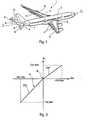
- the characteristic of the airplane 1giving, in a system of rectangular axes, the steering angle ⁇ q of the elevators 8 as a function of the steering order ⁇ m at the handle comprises a portion to be stitched PAP, generally linear, and a PAC nose-up portion, generally linear as well, said nose-and-nose portions being connected to each other at a neutral point N.
- the steer-deflection of the control surfaces 8varies between 0 and a maximum value + ⁇ qmax (and conversely between + ⁇ qmax and 0).
- the steering pitch of the control surfaces 8varies. between 0 and a maximum value - ⁇ qmax (and conversely between - ⁇ qmax and 0).
- the characteristic 14 of the figure 3so that the steering angle ⁇ q takes a value to pitch - ⁇ qo (capable of generating the offset value DP2) when the steering command ⁇ m is zero (see FIG. Figures 4 and 5 ).
- an intermediate portion 16Bfor example rectilinear
- the DP2 value of the offset DPmust also decrease accordingly.
- the value DP2must therefore decrease with the feedrate V of the airplane 1, so that the same is true of the absolute value
- the switching device 18switches back to reconnect the contacts a and c and the characteristic 14 is again available on the common contact c.
- the gradient limiter 19makes it possible to eliminate the additional pitch-up moment when the braking moment CB disappears.
- the system for improving the braking efficiency of an aircraftis not limited to the embodiment shown schematically by the figure 6 and given by way of example to make the invention better understood.
- the system of figure 6could be modified so that the device 17, generating the characteristic 14, and the computer 27, generating the characteristics 15 or 16, have common parts.
Landscapes
- Engineering & Computer Science (AREA)
- Aviation & Aerospace Engineering (AREA)
- Automation & Control Theory (AREA)
- Mechanical Engineering (AREA)
- Braking Arrangements (AREA)
- Vehicle Body Suspensions (AREA)
- Elevator Control (AREA)
- Hydraulic Control Valves For Brake Systems (AREA)
- Consolidation Of Soil By Introduction Of Solidifying Substances Into Soil (AREA)
- Testing Of Balance (AREA)
Abstract
Description
Translated fromFrenchLa présente invention concerne un procédé et un dispositif pour améliorer l'efficacité de freinage d'un aéronef roulant sur le sol.The present invention relates to a method and a device for improving the braking efficiency of an aircraft taxiing on the ground.
On sait que les avions actuels, notamment les avions de transport civil, comportent un fuselage allongé supporté, au sol, par un train d'atterrissage principal, disposé en position intermédiaire dudit fuselage, et par un train avant orientable, généralement appelé roulette de nez. De plus, les roues du train principal sont munies de freins, alors que ledit train avant, qui sert au guidage latéral de l'avion au sol, comporte des roues non freinées.It is known that current aircraft, including civil transport aircraft, comprise an elongated fuselage supported, on the ground, by a main landing gear disposed in an intermediate position of said fuselage, and by a steerable nose gear, generally called a nose wheel. . In addition, the wheels of the main gear are provided with brakes, while said nose gear, which serves for lateral guidance of the aircraft on the ground, has unrestrained wheels.
Il résulte de ces dispositions que, lorsqu'un tel avion roulant sur le sol est freiné, la force de freinage exercée par les roues du train principal engendre un moment piqueur ayant tendance à décharger ledit train principal et à charger ledit train avant. Par suite, le train principal ne s'applique pas sur le sol avec une pression suffisante pour permettre une efficacité du freinage optimale à l'avion.It follows from these provisions that, when such a plane rolling on the ground is braked, the braking force exerted by the wheels of the main gear generates a breaker moment tending to unload said main gear and to load said nose gear. As a result, the main gear does not apply to the ground with sufficient pressure to allow optimal braking efficiency to the aircraft.
La présente invention a pour objet de remédier à cet inconvénient et à conférer à un tel avion roulant sur le sol une efficacité de freinage toujours optimale.The present invention aims to overcome this disadvantage and to confer such an aircraft rolling on the ground braking efficiency always optimal.
A cette fin, selon l'invention, le procédé pour améliorer l'efficacité de freinage d'un aéronef roulant sur le sol, ledit aéronef comportant un fuselage allongé et étant pourvu :
- d'un train principal disposé en position intermédiaire dudit fuselage et comprenant des roues munies de freins ;
- d'un train avant orientable, disposé à l'avant dudit fuselage et servant au guidage latéral dudit aéronef au sol, ledit train avant comportant des roues non freinées ; et
- des surfaces aérodynamiques commandables, disposées à l'arrière du fuselage et aptes à engendrer une force de déportance variable,
- dans une phase préalable, on détermine une valeur de référence pour l'effort vertical appliqué par le sol sur ledit train avant, ladite valeur de référence étant apte à assurer une efficacité satisfaisante audit train avant pour le guidage latéral dudit aéronef lorsque celui-ci roule sur le sol ; puis
- pendant le freinage dudit aéronef roulant sur le sol :
- ■ on mesure l'effort vertical instantané appliqué réellement par le sol sur ledit train avant ; et
- ■ on commande lesdites surfaces aérodynamiques arrière pour qu'elles engendrent une valeur de déportance apte à maintenir ledit effort vertical instantané à une valeur au moins approximativement égale à ladite valeur de référence.
- a main gear disposed in an intermediate position of said fuselage and comprising wheels provided with brakes;
- a steerable front train, arranged in front of said fuselage and serving for lateral guidance of said aircraft on the ground, said front axle comprising unbraked wheels; and
- controllable aerodynamic surfaces arranged at the rear of the fuselage and capable of generating a variable deportation force,
- in a prior phase, a reference value is determined for the vertical force applied by the ground on said nose gear, said reference value being able to ensure satisfactory efficiency to said nose gear for lateral guidance of said aircraft when it is rolling. On the ground ; then
- during braking of said aircraft taxiing on the ground:
- ■ the instantaneous vertical force actually applied by the ground on said nose gear is measured; and
- Said rear aerodynamic surfaces are controlled so that they generate a deportance value able to maintain said instantaneous vertical force at a value at least approximately equal to said reference value.
Ainsi, grâce à la présente invention, on crée un moment cabreur antagoniste dudit moment piqueur de freinage et on augmente l'efficacité du freinage de l'aéronef -et donc on réduit la longueur de piste nécessaire à l'arrêt de ce dernier- par contrôle de l'effort vertical sur le train avant, tout en gardant une possibilité de guidage latéral suffisant de l'aéronef par le train avant. On remarquera de plus que, par braquage desdites surfaces aérodynamiques arrière, on augmente la traînée de l'aéronef, ce qui est favorable au freinage.Thus, by virtue of the present invention, an upward tilting moment of said braking moment is created and the braking efficiency of the aircraft is increased, and thus the length of the track necessary for stopping the latter is reduced by control of the vertical force on the front axle, while keeping a possibility of sufficient lateral guidance of the aircraft by the nose gear. It will further be noted that, by deflection of said rear aerodynamic surfaces, the drag of the aircraft is increased, which is favorable to braking.
Ladite valeur de référence pour l'effort vertical appliqué par le sol sur ledit train avant peut être déterminée par le calcul ou bien par mesure expérimentale directe sur ledit train avant. Elle est choisie pour permettre d'assurer un contrôle latéral suffisant de l'aéronef et pour conserver une marge d'autorité au manche.Said reference value for the vertical force applied by the ground on said nose gear can be determined by calculation or by direct experimental measurement on said nose gear. It is chosen to ensure sufficient lateral control of the aircraft and to maintain a margin of authority on the stick.
Lorsque ledit aéronef comporte, comme surfaces aérodynamiques arrière commandables, à la fois un empennage horizontal réglable et des gouvernes de profondeur articulées audit empennage, la génération de ladite valeur de déportance peut être obtenue soit par action sur ledit empennage horizontal réglable, soit par action sur lesdites gouvernes de profondeur ou bien encore par actions simultanées sur ledit empennage horizontal réglable et sur lesdites gouvernes de profondeur.When said aircraft comprises, as controllable rear aerodynamic surfaces, both an adjustable horizontal stabilizer and elevators articulated to said empennage, the generation of said deportation value can be obtained either by action on said adjustable horizontal stabilizer, or by action on said elevators or by simultaneous actions on said adjustable horizontal stabilizer and on said elevators.
Cependant, la mise en oeuvre du procédé conforme à la présente invention est particulièrement aisée lorsqu'on utilise les seules gouvernes de profondeur. En effet, il suffit alors de modifier, pendant la phase de roulement freiné de l'aéronef, la caractéristique de celui-ci donnant le braquage des gouvernes de profondeur en fonction de l'ordre de braquage commandé de façon que, lorsque celui-ci est nul, l'angle de braquage desdites gouvernes prenne une valeur à cabrer.However, the implementation of the method according to the present invention is particularly easy when using the only elevators. In fact, it suffices then to modify, during the braking phase of the aircraft, the characteristic of the latter giving the steering of the elevators as a function of the controlled steering order so that, when the latter is zero, the steering angle of said control surfaces takes a pitching value.
La présente invention concerne de plus un dispositif pour la mise en oeuvre du procédé décrit ci-dessus. Outre des moyens engendrant une caractéristique donnant l'angle de braquage des gouvernes de profondeur en fonction d'un ordre de braquage, ladite caractéristique ayant un point neutre, le dispositif selon l'invention peut comporter :
- des moyens pour la mesure en continu de l'effort vertical appliqué audit train avant orientable, lorsque ledit aéronef roule sur le sol en étant freiné ;
- des moyens de mémoire, dans lesquels est stockée ladite valeur de référence ;
- des moyens de comparaison recevant ladite mesure continue dudit effort vertical et ladite valeur de référence et en faisant la différence ;
- des moyens de calcul recevant ladite différence et une mesure de la vitesse de roulement dudit aéronef et délivrant, pour l'angle de braquage desdites gouvernes de profondeur, une valeur à cabrer non nulle lorsque l'ordre de braquage est nul, ladite valeur à cabrer non nulle décroissant avec la vitesse de l'aéronef ;
- des moyens de calcul qui, à partir de ladite valeur à cabrer non nulle, détermine une caractéristique modifiée donnant l'angle de braquage des gouvernes de profondeur en fonction de l'ordre de braquage ; et
- des moyens de commutation permettant d'appliquer auxdites gouvernes de profondeur soit ladite caractéristique usuelle, soit ladite caractéristique modifiée, en fonction du fait que les roues du train principal ne sont pas ou sont freinées.
- means for continuously measuring the vertical force applied to said steerable nose gear, when said aircraft rolls on the ground while being braked;
- memory means, in which said reference value is stored;
- comparison means receiving said continuous measurement of said vertical force and said reference value and making the difference;
- calculation means receiving said difference and a measurement of the running speed of said aircraft and delivering, for the steering angle of said elevators, a non-zero nose-up value; when the steering order is zero, said non-zero pitch up value decreasing with the speed of the aircraft;
- calculating means which, from said non-zero nose up value, determines a modified characteristic giving the steering angle of the elevators as a function of the steering order; and
- switching means for applying to said elevators either said usual characteristic or said modified characteristic, depending on the fact that the wheels of the main gear are not or are braked.
Les figures du dessin annexé feront bien comprendre comment l'invention peut être réalisée. Sur ces figures, des références identiques désignent des éléments semblables.
- La
figure 1 montre, en perspective schématique du dessus, un aéronef civil gros porteur. - Les
figures 2A, 2B et 2C illustrent le procédé de la présente invention. - La
figure 3 montre une caractéristique usuelle d'avion indiquant la valeur de l'angle de braquage δq des gouvernes de profondeur dudit avion en fonction de l'ordre de braquage δm. - Les
figures 4 et 5 montrent deux exemples de caractéristique δq, δm modifiée conformément à la présente invention. - La
figure 6 est le schéma synoptique d'un exemple de réalisation d'un système mettant en oeuvre le procédé conforme à la présente invention.
- The
figure 1 shows, in schematic perspective from above, a large civil aircraft. - The
FIGS. 2A, 2B and 2C illustrate the process of the present invention. - The
figure 3 shows a usual aircraft characteristic indicating the value of the steering angle δq of the elevators of said airplane as a function of the steering order δm. - The
Figures 4 and 5 show two examples of characteristic δq, δm modified according to the present invention. - The
figure 6 is the block diagram of an exemplary embodiment of a system implementing the method according to the present invention.
L'avion gros porteur 1, montré schématiquement en vol par la
Par ailleurs, comme cela est illustré sur les
Sur les
Dans la situation représentée sur la
Sur la
Pour permettre d'accroître l'effort de freinage au-delà de la valeur B1, le procédé conforme à la présente invention (voir la
Ainsi, en communiquant à la déportance DP une valeur DP2 supérieure à la valeur usuelle DP1 utilisée dans les situations des
Le procédé conforme à la présente invention consiste donc à asservir, à la valeur Fav3 servant de référence, l'effort vertical Fav appliqué par le sol sur le train avant 12, par commande de la déportance DP.The method according to the present invention therefore consists in controlling, at the value Fav3 serving as a reference, the vertical force Fav applied by the ground on the
Comme mentionné ci-dessus, l'augmentation de la déportance DP de la valeur DP1 à la valeur DP2 peut être obtenue soit par action de l'empennage horizontal réglable 6, soit par action des gouvernes de profondeur 8, ou bien encore par action combinée de l'empennage horizontal réglable 6 et des gouvernes de profondeur 8. Toutefois, dans une forme de réalisation particulièrement aisée à mettre en oeuvre, il est avantageux de ne faire intervenir que les gouvernes de profondeur 8.As mentioned above, the increase of the DP offset from the value DP1 to the value DP2 can be obtained either by action of the adjustable
On sait en effet que, de façon connue, comme cela est illustré par la courbe 14 de la
Selon une particularité importante de la présente invention, pour obtenir une valeur de déportance DP2 supérieure à la valeur DP1, alors que le manche est au neutre, on modifie la caractéristique 14 de la
Dans l'exemple de réalisation illustré par la
En variante, dans l'exemple de modification de caractéristique montré par la
On comprendra aisément que les caractéristiques 15 et 16 des
Par ailleurs, puisque, au fur et à mesure de l'action de freinage B, la vitesse d'avance V de l'avion 1 sur le sol S décroît, il en résulte que la valeur de la portance P décroît, augmentant en conséquence la valeur des efforts Ftp et Fav et que, pour obtenir la même valeur Fav3 de l'effort vertical Fav sur le train avant 12, la valeur DP2 de la déportance DP doit également décroître en conséquence. La valeur DP2 doit donc décroître avec la vitesse d'avance V de l'avion 1, de sorte qu'il en est de même de la valeur absolue |δqo| de l'angle de braquage -δqo engendrant la valeur de déportance DP2, lorsque l'ordre de braquage δm est nul.Moreover, since, as the braking action B, the speed of advance V of the
Sur la
un dispositif 17 connu, engendrant la caractéristique usuelle 14 (ou tout autre caractéristique analogue) présentant un point neutre N, pour lequel δm = 0 et δq = 0 ;- un dispositif de
commutation 18 comportant un contact de repos a auquel ledit dispositif 17 est relié par l'intermédiaire d'un limiteur de gradient (par exemple 20°/s), ledit dispositif decommutation 18 comportant un autre contact de travail b et un contact commun c relié à la chaîne de commande des gouvernes de profondeur 8 ; un dispositif 20 pour engendrer un ordre de freinage des roues 11 dutrain d'atterrissage principal 10,ledit dispositif 20 commandant le basculement du dispositif decommutation 18 de sa position de repos à sa position de travail, par l'intermédiaire d'un compteur 21 ;- des moyens 22 de mesure de l'effort vertical réel Fav appliqué au train avant orientable 12 pendant le roulement de l'avion 1 sur le sol S, lesdits moyens étant par exemple du type capteur d'effort ou capteur de pression ;
- des moyens à mémoire 23, dans lesquels est stockée la valeur de référence Fav3 pour ledit effort vertical Fav ;
- des moyens de comparaison 24 recevant à leurs entrées, respectivement la valeur de référence Fav3 provenant des moyens à mémoire 23 et la mesure de l'effort vertical Fav provenant des moyens de mesure 22 par l'intermédiaire d'un filtre 25 ;
un multiplicateur 26, permettant de multiplier le signal de différence, issu des moyens de comparaison 24, par un coefficient K, constant ou fonction de la vitesse V, représentatif de l'efficacité des gouvernes de profondeur 8 sur l'effort vertical Fav appliquéau train avant 12 ;un calculateur 27, recevant le signal issu du multiplicateur 26 et un signal représentatif de la vitesse instantanée de l'avion 1 et engendrant la valeur absolue |δqo|, décroissant avec la vitesse V, apte à assurer à chaque instant la déportance DP2 nécessaire pour obtenir la valeur d'effort désirée sur letrain avant 12 ;- un limiteur de gradient 28 (
par exemple 5°/s) recevant ladite valeur absolue |δqo| ; et - des moyens de calcul 29 qui, à partir de ladite valeur absolue |δqo| reçue du limiteur de
gradient 28, détermine la caractéristique 15 ou 16 (ou toute autre caractéristique analogue) et la transmet au contact de travail b du dispositif decommutation 18.
- a known
device 17, generating the usual characteristic 14 (or any other similar characteristic) having a neutral point N, for which δm = 0 and δq = 0; - a
switching device 18 comprising a quiescent contact to which saiddevice 17 is connected via a gradient limiter (for example 20 ° / s), said switchingdevice 18 comprising another working contact b and a common contact c connected to the control chain ofelevators 8; - a
device 20 for generating a braking order of thewheels 11 of themain landing gear 10, saiddevice 20 controlling the tilting of theswitching device 18 from its rest position to its working position, via acounter 21; - means 22 for measuring the actual vertical force Fav applied to the steerable
front axle 12 during the rolling of theaircraft 1 on the ground S, said means being for example of the force sensor or pressure sensor type; - memory means 23, in which is stored the reference value Fav3 for said vertical force Fav;
- comparison means 24 receiving at their inputs respectively the reference value Fav3 from the memory means 23 and the measurement of the vertical force Fav from the measuring means 22 via a
filter 25; - a
multiplier 26, making it possible to multiply the difference signal, derived from the comparison means 24, by a coefficient K, constant or a function of the speed V, representative of the efficiency of theelevators 8 on the vertical force Fav applied to thefront train 12; - a
computer 27, receiving the signal from themultiplier 26 and a signal representative of the instantaneous speed of theaircraft 1 and generating the absolute value | δqo |, decreasing with the speed V, able to ensure at every moment the DP2 offset necessary for obtain the desired force value on thefront axle 12; - a gradient limiter 28 (for example 5 ° / s) receiving said absolute value | δqo | ; and
- calculating means 29 which, from said absolute value | δqo | received from the
gradient limiter 28, determines the characteristic 15 or 16 (or any other similar characteristic) and transmits it to the working contact b of theswitching device 18.
Ainsi, lorsque l'avion 1 roule sur le sol S sans freiner, c'est la caractéristique 14 (ou toute caractéristique analogue avec point neutre N) qui est disponible pour commander les gouvernes de profondeur 8, à travers la chaîne 17, 19, a et c.Thus, when the
En revanche, lorsqu'un ordre de freinage engendré par le dispositif 20 est appliqué sur les roues 1 du train principal 10 pendant un temps prédéterminé par le compteur 21, ce dernier fait basculer le dispositif de commutation 18, de façon que le contact commun c soit alors relié au contact b. Dans ce cas, c'est la caractéristique 15 (ou la caractéristique 16 -ou tout autre caractéristique avec un point δm = 0,δq = -δqo) qui apparaît sur le contact commun c pour commander les gouvernes de profondeur 8.In contrast, when a braking command generated by the
Lorsque l'ordre de freinage cesse, le dispositif de commutation 18 rebascule de façon à relier de nouveau les contacts a et c et la caractéristique 14 est de nouveau disponible sur le contact commun c. Le limiteur de gradient 19 permet d'éliminer le moment à cabrer supplémentaire lorsque le moment de freinage CB disparaît.When the braking command ceases, the switching
Le système pour améliorer l'efficacité de freinage d'un aéronef, conforme à la présente invention, n'est pas limité au mode de réalisation montré schématiquement par la
Claims (7)
- A method for enhancing the braking efficiency of an aircraft (1) taxiing on the ground (S), said aircraft (1) comprising an elongated fuselage (2) and being provided:- with a main landing gear (10), disposed in an intermediate position of said fuselage (2) and comprising wheels (11) provided with brakes;- with a steerable front landing gear (12), disposed at the front of said fuselage (2) and being used to laterally guide said aircraft (1) on the ground, said front landing gear (12) comprising wheels (13) without brakes; and- with controllable aerodynamic surfaces (6, 8) disposed at the rear of the fuselage (2) and capable of generating a variable negative lift force (DP),characterized in that:- in a preliminary phase, a reference value (Fav3) is determined for the vertical force (Fav) exerted by the ground (S) on said front landing gear (12), said reference value being capable of ensuring a satisfactory efficiency of said front landing gear (12) for the lateral guiding of said aircraft (1) when the latter is taxiing on the ground (S); then- while said aircraft (1) taxiing on the ground (S) is braking:• the instantaneous vertical force (Fav) actually exerted by the ground (S) on said front landing gear (12) is measured; and• said rear aerodynamic surfaces (6, 8) are controlled so that they generate a negative lift value (DP2) capable of maintaining said instantaneous vertical force (Fav) at a value at least approximately equal to said reference value (Fav3).
- The method as claimed in claim 1,characterized in that said negative lift value (DP2) decreases with the speed of said aircraft (1).
- The method as claimed in one of claims 1 or 2, applied to an aircraft (1) comprising an adjustable horizontal stabilizer (6) and elevators (8) hinged on said adjustable horizontal stabilizer (6),
characterized in that said negative lift value (DP2) is obtained at least partly by controlling said adjustable horizontal stabilizer (6). - The method as claimed in one of claims 1 to 3, applied to an aircraft (1) with rear aerodynamic surfaces that include elevators (8),
characterized in that said negative lift value (DP2) is obtained at least partly by controlling said elevators (8). - The method as claimed in claim 4,
characterized in that said negative lift value (DP2) is obtained by controlling the elevators (8) alone andin that the characteristic giving the deflection angle (δq) of said elevators (8) is modified according to the deflection command (δm), such that, when said deflection command (δm) is zero, the deflection angle (δq) assumes a nose-up value (-δqo). - The method as claimed in claim 5,
characterized in that the absolute value |δqo| of said nose-up value (-δqo) decreases with the speed of said aircraft (1). - A device for implementing the method as claimed in claim 6, provided with means (17, 19) generating a characteristic (14) giving the deflection angle (δq) of the elevators (8) according to a deflection command (δm), said characteristic (14) having a neutral point (N) (for which δq = 0 and δm = 0),
characterized in that it comprises:- means (22) for continuously measuring the vertical force (Fav) exerted on said steerable front landing gear (12), when said aircraft (1) is taxiing on the ground with the brakes being applied;- memory means (23), in which is stored said reference value (Fav3);- comparison means (24) receiving said continuous measurement of said vertical force (Fav) and said reference value (Fav3) and calculating the difference;- computation means (27) receiving said difference and a measurement of the taxiing speed (V) of said aircraft and delivering, for the deflection angle (δq) of said elevators (8), a nose-up value (-δqo) that is non-zero when the deflection command (δm) is zero, said non-zero nose-up value decreasing with the speed (V) of the aircraft;- computation means (29) which, from said non-zero nose-up value, determine a modified characteristic (15, 16) giving the deflection angle (δq) of the elevators (8) according to the deflection command (δm) ; and- switching means (18) for applying to said elevators (8) either said usual characteristic (14), or said modified characteristic (15, 16), depending on whether the wheels (11) of the main landing gear (10) have the brakes applied or not.
Applications Claiming Priority (2)
| Application Number | Priority Date | Filing Date | Title |
|---|---|---|---|
| FR0411634AFR2877312B1 (en) | 2004-11-02 | 2004-11-02 | METHOD AND DEVICE FOR IMPROVING THE BRAKING EFFICIENCY OF A FLYING AIRCRAFT ON THE GROUND |
| PCT/FR2005/002574WO2006048519A1 (en) | 2004-11-02 | 2005-10-18 | Method and device for enhancing the braking efficiency of an aircraft during the ground run thereof |
Publications (2)
| Publication Number | Publication Date |
|---|---|
| EP1807304A1 EP1807304A1 (en) | 2007-07-18 |
| EP1807304B1true EP1807304B1 (en) | 2008-03-19 |
Family
ID=34950931
Family Applications (1)
| Application Number | Title | Priority Date | Filing Date |
|---|---|---|---|
| EP05809326AExpired - LifetimeEP1807304B1 (en) | 2004-11-02 | 2005-10-18 | Method and device for enhancing the braking efficiency of an aircraft during the ground run thereof |
Country Status (11)
| Country | Link |
|---|---|
| US (1) | US7708223B2 (en) |
| EP (1) | EP1807304B1 (en) |
| JP (1) | JP4714221B2 (en) |
| CN (1) | CN100509557C (en) |
| AT (1) | ATE389582T1 (en) |
| BR (1) | BRPI0516920B1 (en) |
| CA (1) | CA2581436C (en) |
| DE (1) | DE602005005513T2 (en) |
| FR (1) | FR2877312B1 (en) |
| RU (1) | RU2341409C1 (en) |
| WO (1) | WO2006048519A1 (en) |
Families Citing this family (20)
| Publication number | Priority date | Publication date | Assignee | Title |
|---|---|---|---|---|
| FR2893909B1 (en)* | 2005-11-29 | 2007-12-21 | Airbus France Sas | METHOD FOR ENSURING THE SAFETY OF A HORIZONTALLY LOW SPEED AIRCRAFT. |
| US8548652B2 (en)* | 2006-01-31 | 2013-10-01 | Hydro-Aire, Inc., Subsidiary Of Crane Co. | System for reducing carbon brake wear |
| FR2918638B1 (en)* | 2007-07-09 | 2010-02-26 | Airbus France | SYSTEM FOR LIMITING TANGUE OSCILLATIONS APPLIED TO AN AIRCRAFT. |
| US20100301170A1 (en)* | 2009-05-29 | 2010-12-02 | Arin Boseroy | Control system for actuation system |
| FR2973776B1 (en)* | 2011-04-07 | 2013-04-05 | Messier Bugatti | ARCHITECTURE OF BRAKING SYSTEM FOR AIRCRAFT. |
| FR2982822B1 (en)* | 2011-11-22 | 2014-08-01 | Messier Bugatti Dowty | METHOD FOR BRAKING AN AIRCRAFT FOR LIMITING ITS TANGING |
| RU2484279C1 (en)* | 2011-12-19 | 2013-06-10 | Николай Евгеньевич Староверов | Method for improving braking efficiency of aircraft during ground rolling and increasing safety at takeoff and landing, and device for its implementation |
| CN102582602B (en)* | 2012-03-05 | 2014-12-31 | 西安航空制动科技有限公司 | Method for controlling brake efficiency of aircraft carbon brake disc in wet state |
| GB201315012D0 (en) | 2013-08-22 | 2013-10-02 | Airbus Uk Ltd | Aircraft autonomous pushback |
| CN103612750A (en)* | 2013-11-20 | 2014-03-05 | 渭南高新区晨星专利技术咨询有限公司 | Anti-skid brake control system of airplane |
| CN106794899B (en)* | 2014-10-14 | 2019-07-05 | 特温技术公司 | Flight equipment |
| US9731813B2 (en)* | 2014-11-12 | 2017-08-15 | The Boeing Company | Methods and apparatus to control aircraft horizontal stabilizers |
| EP3448749B1 (en)* | 2016-04-25 | 2020-07-01 | Bombardier Inc. | Aircraft pitch control system with electronically geared elevator |
| US10086925B2 (en)* | 2016-07-13 | 2018-10-02 | Embraer S.A. | Use of automatic pitch control to improve braking performance |
| CN108398883B (en)* | 2018-02-27 | 2021-02-09 | 北京控制工程研究所 | RLV approach landing trajectory rapid deduction and determination method |
| CN109157847B (en)* | 2018-11-06 | 2023-11-24 | 大连理工大学 | Fixed wing aeromodelling structure based on carbon rod and installation method |
| RU2722597C1 (en)* | 2019-10-18 | 2020-06-02 | Федеральное государственное унитарное предприятие "Центральный аэрогидродинамический институт имени профессора Н.Е. Жуковского" (ФГУП "ЦАГИ") | Method of aircraft braking during landing |
| CN111976963A (en)* | 2020-07-08 | 2020-11-24 | 西安航空制动科技有限公司 | 6-wheel frame main landing gear airplane fly-by-wire brake control system and method |
| US11897597B2 (en)* | 2020-07-20 | 2024-02-13 | The Boeing Company | Flap pressure shape biasing |
| WO2025030231A1 (en)* | 2023-08-10 | 2025-02-13 | Safran Landing Systems Canada Inc. | Pitch attitude control system for increasing aircraft braking efficiency |
Family Cites Families (11)
| Publication number | Priority date | Publication date | Assignee | Title |
|---|---|---|---|---|
| GB754405A (en)* | 1954-04-13 | 1956-08-08 | Goodyear Tire & Rubber | Apparatus for landing aircraft |
| FR2542277B1 (en)* | 1983-03-08 | 1985-06-28 | Messier Hispano Sa | METHOD AND DEVICE FOR CONTROLLING THE BRAKING OF AN AIRCRAFT DURING THE LANDING WHEN IT HAS CONTACT WITH THE GROUND OF A RUNWAY THROUGH ITS MAIN LANDING GEARS AND WHEN THE FRONT AXLE HAS NOT YET TAKEN CONTACT WITH FLOOR |
| DE3481943D1 (en)* | 1984-01-27 | 1990-05-17 | Boeing Co | AUTOMATIC BRAKE SYSTEM FOR AIRCRAFT. |
| US4646254A (en)* | 1984-10-09 | 1987-02-24 | Gte Government Systems Corporation | Noise threshold estimating method for multichannel signal processing |
| JPH01106765A (en)* | 1987-10-19 | 1989-04-24 | Yokogawa Electric Corp | anti-skid brake system |
| DE3803015A1 (en)* | 1988-02-02 | 1989-08-10 | Pfister Gmbh | Method and system for operating (driving) an aircraft |
| RU2009077C1 (en)* | 1991-12-16 | 1994-03-15 | Мамулин Андрей Викторович | Device for regulating vehicles wheels braking |
| EP0754405A1 (en)* | 1995-07-21 | 1997-01-22 | Tiziano Faccia | Improved machine for shredding and mixing fibrous products for technical use in zoo |
| JPH09164932A (en)* | 1995-12-15 | 1997-06-24 | Aisin Seiki Co Ltd | Vehicle motion control device |
| US5823479A (en)* | 1996-05-20 | 1998-10-20 | The Boeing Company | Landing attitude modifier for airplane |
| US6220676B1 (en)* | 1997-05-09 | 2001-04-24 | The B. F. Goodrich Company | Antiskid control of multi-wheel vehicles using coupled and decoupled Kalman filtering incorporating pitch weight transfer |
- 2004
- 2004-11-02FRFR0411634Apatent/FR2877312B1/ennot_activeExpired - Fee Related
- 2005
- 2005-10-18USUS11/718,490patent/US7708223B2/ennot_activeExpired - Fee Related
- 2005-10-18BRBRPI0516920-8Apatent/BRPI0516920B1/ennot_activeIP Right Cessation
- 2005-10-18CNCNB2005800377666Apatent/CN100509557C/ennot_activeExpired - Fee Related
- 2005-10-18RURU2007116106/11Apatent/RU2341409C1/ennot_activeIP Right Cessation
- 2005-10-18WOPCT/FR2005/002574patent/WO2006048519A1/enactiveIP Right Grant
- 2005-10-18JPJP2007538461Apatent/JP4714221B2/ennot_activeExpired - Lifetime
- 2005-10-18EPEP05809326Apatent/EP1807304B1/ennot_activeExpired - Lifetime
- 2005-10-18ATAT05809326Tpatent/ATE389582T1/ennot_activeIP Right Cessation
- 2005-10-18DEDE602005005513Tpatent/DE602005005513T2/ennot_activeExpired - Lifetime
- 2005-10-18CACA2581436Apatent/CA2581436C/ennot_activeExpired - Fee Related
Also Published As
| Publication number | Publication date |
|---|---|
| WO2006048519A1 (en) | 2006-05-11 |
| DE602005005513D1 (en) | 2008-04-30 |
| FR2877312B1 (en) | 2007-01-12 |
| FR2877312A1 (en) | 2006-05-05 |
| CA2581436A1 (en) | 2006-05-11 |
| JP4714221B2 (en) | 2011-06-29 |
| CA2581436C (en) | 2012-05-29 |
| EP1807304A1 (en) | 2007-07-18 |
| RU2341409C1 (en) | 2008-12-20 |
| BRPI0516920B1 (en) | 2018-01-16 |
| ATE389582T1 (en) | 2008-04-15 |
| US7708223B2 (en) | 2010-05-04 |
| US20090065636A1 (en) | 2009-03-12 |
| CN101052564A (en) | 2007-10-10 |
| BRPI0516920A (en) | 2008-09-23 |
| CN100509557C (en) | 2009-07-08 |
| DE602005005513T2 (en) | 2009-04-23 |
| JP2008518821A (en) | 2008-06-05 |
Similar Documents
| Publication | Publication Date | Title |
|---|---|---|
| EP1807304B1 (en) | Method and device for enhancing the braking efficiency of an aircraft during the ground run thereof | |
| EP0296951B1 (en) | Yaw and roll control system for an aircraft | |
| CA2427357C (en) | Aircraft with wing active wash control | |
| EP0032853B1 (en) | Process and device for braking an aircraft by defining optimum slip of the braked wheels | |
| EP0566452B1 (en) | Single-rotor helicopter with mixed counter-torque system and method to counter the torque induced by this single rotor | |
| EP1989104B1 (en) | Electrical control system for an aircraft steering vane | |
| EP1880259A2 (en) | Assisted take-off method for aircraft | |
| EP1904359A1 (en) | Vehicle steering system comprising a degraded operating mode in case of breakdown of a wheel steering actuator | |
| EP1591854B1 (en) | Aircraft take off procedure | |
| EP1440880B1 (en) | Method and system for actuating aircraft control surfaces | |
| FR3024249A1 (en) | METHOD AND SYSTEM FOR CONTROLLING FLIGHT OF AN AIRCRAFT | |
| EP0454549B1 (en) | Aircraft pitch attitude control system | |
| EP3271244B1 (en) | Aircraft flight control device | |
| EP0953504B1 (en) | Aircraft with reduced wing loads | |
| FR2769284A1 (en) | Control device of helicopter tail rotor aerodynamic steering surface | |
| CA2437216C (en) | Procedure and system to move the elevator of an aircraft | |
| FR3080362A1 (en) | IMPROVED FIXED SAIL DRONE, CONTROL AND LANDING METHOD | |
| CA2586892C (en) | Method for improving roll steering of an aircraft and aircraft using same | |
| CA2500838C (en) | Process and unit for controlling and braking a taxiing aircraft | |
| FR3035235A1 (en) | METHOD AND SYSTEM FOR CONTROLLING FLIGHT OF AN AIRCRAFT ACCORDING TO THE AXIS OF TANGING | |
| FR3008368A1 (en) | METHOD FOR MANAGING THE BRAKING OF AN AIRCRAFT | |
| FR2769285A1 (en) | Control device for helicopter tail rotor | |
| FR2771706A1 (en) | Aerodynamic pitch and trim control for helicopter | |
| EP2597002B1 (en) | Braking control method for landed airplane, aiming to optimise its pitching anle. |
Legal Events
| Date | Code | Title | Description |
|---|---|---|---|
| PUAI | Public reference made under article 153(3) epc to a published international application that has entered the european phase | Free format text:ORIGINAL CODE: 0009012 | |
| 17P | Request for examination filed | Effective date:20070410 | |
| AK | Designated contracting states | Kind code of ref document:A1 Designated state(s):AT BE BG CH CY CZ DE DK EE ES FI FR GB GR HU IE IS IT LI LT LU LV MC NL PL PT RO SE SI SK TR | |
| GRAP | Despatch of communication of intention to grant a patent | Free format text:ORIGINAL CODE: EPIDOSNIGR1 | |
| DAX | Request for extension of the european patent (deleted) | ||
| GRAS | Grant fee paid | Free format text:ORIGINAL CODE: EPIDOSNIGR3 | |
| GRAA | (expected) grant | Free format text:ORIGINAL CODE: 0009210 | |
| AK | Designated contracting states | Kind code of ref document:B1 Designated state(s):AT BE BG CH CY CZ DE DK EE ES FI FR GB GR HU IE IS IT LI LT LU LV MC NL PL PT RO SE SI SK TR | |
| REG | Reference to a national code | Ref country code:GB Ref legal event code:FG4D Free format text:NOT ENGLISH | |
| REG | Reference to a national code | Ref country code:CH Ref legal event code:EP | |
| REF | Corresponds to: | Ref document number:602005005513 Country of ref document:DE Date of ref document:20080430 Kind code of ref document:P | |
| REG | Reference to a national code | Ref country code:IE Ref legal event code:FG4D Free format text:LANGUAGE OF EP DOCUMENT: FRENCH | |
| REG | Reference to a national code | Ref country code:SE Ref legal event code:TRGR | |
| PG25 | Lapsed in a contracting state [announced via postgrant information from national office to epo] | Ref country code:FI Free format text:LAPSE BECAUSE OF FAILURE TO SUBMIT A TRANSLATION OF THE DESCRIPTION OR TO PAY THE FEE WITHIN THE PRESCRIBED TIME-LIMIT Effective date:20080319 Ref country code:LT Free format text:LAPSE BECAUSE OF FAILURE TO SUBMIT A TRANSLATION OF THE DESCRIPTION OR TO PAY THE FEE WITHIN THE PRESCRIBED TIME-LIMIT Effective date:20080319 | |
| PG25 | Lapsed in a contracting state [announced via postgrant information from national office to epo] | Ref country code:AT Free format text:LAPSE BECAUSE OF FAILURE TO SUBMIT A TRANSLATION OF THE DESCRIPTION OR TO PAY THE FEE WITHIN THE PRESCRIBED TIME-LIMIT Effective date:20080319 | |
| NLV1 | Nl: lapsed or annulled due to failure to fulfill the requirements of art. 29p and 29m of the patents act | ||
| PG25 | Lapsed in a contracting state [announced via postgrant information from national office to epo] | Ref country code:PL Free format text:LAPSE BECAUSE OF FAILURE TO SUBMIT A TRANSLATION OF THE DESCRIPTION OR TO PAY THE FEE WITHIN THE PRESCRIBED TIME-LIMIT Effective date:20080319 Ref country code:SI Free format text:LAPSE BECAUSE OF FAILURE TO SUBMIT A TRANSLATION OF THE DESCRIPTION OR TO PAY THE FEE WITHIN THE PRESCRIBED TIME-LIMIT Effective date:20080319 Ref country code:LV Free format text:LAPSE BECAUSE OF FAILURE TO SUBMIT A TRANSLATION OF THE DESCRIPTION OR TO PAY THE FEE WITHIN THE PRESCRIBED TIME-LIMIT Effective date:20080319 | |
| REG | Reference to a national code | Ref country code:IE Ref legal event code:FD4D | |
| PG25 | Lapsed in a contracting state [announced via postgrant information from national office to epo] | Ref country code:SK Free format text:LAPSE BECAUSE OF FAILURE TO SUBMIT A TRANSLATION OF THE DESCRIPTION OR TO PAY THE FEE WITHIN THE PRESCRIBED TIME-LIMIT Effective date:20080319 Ref country code:CZ Free format text:LAPSE BECAUSE OF FAILURE TO SUBMIT A TRANSLATION OF THE DESCRIPTION OR TO PAY THE FEE WITHIN THE PRESCRIBED TIME-LIMIT Effective date:20080319 Ref country code:ES Free format text:LAPSE BECAUSE OF FAILURE TO SUBMIT A TRANSLATION OF THE DESCRIPTION OR TO PAY THE FEE WITHIN THE PRESCRIBED TIME-LIMIT Effective date:20080630 Ref country code:PT Free format text:LAPSE BECAUSE OF FAILURE TO SUBMIT A TRANSLATION OF THE DESCRIPTION OR TO PAY THE FEE WITHIN THE PRESCRIBED TIME-LIMIT Effective date:20080827 | |
| PG25 | Lapsed in a contracting state [announced via postgrant information from national office to epo] | Ref country code:NL Free format text:LAPSE BECAUSE OF FAILURE TO SUBMIT A TRANSLATION OF THE DESCRIPTION OR TO PAY THE FEE WITHIN THE PRESCRIBED TIME-LIMIT Effective date:20080319 Ref country code:RO Free format text:LAPSE BECAUSE OF FAILURE TO SUBMIT A TRANSLATION OF THE DESCRIPTION OR TO PAY THE FEE WITHIN THE PRESCRIBED TIME-LIMIT Effective date:20080319 | |
| PG25 | Lapsed in a contracting state [announced via postgrant information from national office to epo] | Ref country code:IS Free format text:LAPSE BECAUSE OF FAILURE TO SUBMIT A TRANSLATION OF THE DESCRIPTION OR TO PAY THE FEE WITHIN THE PRESCRIBED TIME-LIMIT Effective date:20080719 | |
| PLBE | No opposition filed within time limit | Free format text:ORIGINAL CODE: 0009261 | |
| STAA | Information on the status of an ep patent application or granted ep patent | Free format text:STATUS: NO OPPOSITION FILED WITHIN TIME LIMIT | |
| PG25 | Lapsed in a contracting state [announced via postgrant information from national office to epo] | Ref country code:IE Free format text:LAPSE BECAUSE OF FAILURE TO SUBMIT A TRANSLATION OF THE DESCRIPTION OR TO PAY THE FEE WITHIN THE PRESCRIBED TIME-LIMIT Effective date:20080319 Ref country code:DK Free format text:LAPSE BECAUSE OF FAILURE TO SUBMIT A TRANSLATION OF THE DESCRIPTION OR TO PAY THE FEE WITHIN THE PRESCRIBED TIME-LIMIT Effective date:20080319 | |
| 26N | No opposition filed | Effective date:20081222 | |
| BERE | Be: lapsed | Owner name:AIRBUS FRANCE Effective date:20081031 | |
| PG25 | Lapsed in a contracting state [announced via postgrant information from national office to epo] | Ref country code:EE Free format text:LAPSE BECAUSE OF FAILURE TO SUBMIT A TRANSLATION OF THE DESCRIPTION OR TO PAY THE FEE WITHIN THE PRESCRIBED TIME-LIMIT Effective date:20080319 Ref country code:BG Free format text:LAPSE BECAUSE OF FAILURE TO SUBMIT A TRANSLATION OF THE DESCRIPTION OR TO PAY THE FEE WITHIN THE PRESCRIBED TIME-LIMIT Effective date:20080619 | |
| PG25 | Lapsed in a contracting state [announced via postgrant information from national office to epo] | Ref country code:MC Free format text:LAPSE BECAUSE OF NON-PAYMENT OF DUE FEES Effective date:20081031 | |
| PG25 | Lapsed in a contracting state [announced via postgrant information from national office to epo] | Ref country code:CY Free format text:LAPSE BECAUSE OF FAILURE TO SUBMIT A TRANSLATION OF THE DESCRIPTION OR TO PAY THE FEE WITHIN THE PRESCRIBED TIME-LIMIT Effective date:20080319 Ref country code:BE Free format text:LAPSE BECAUSE OF NON-PAYMENT OF DUE FEES Effective date:20081031 | |
| REG | Reference to a national code | Ref country code:CH Ref legal event code:PL | |
| PG25 | Lapsed in a contracting state [announced via postgrant information from national office to epo] | Ref country code:LU Free format text:LAPSE BECAUSE OF NON-PAYMENT OF DUE FEES Effective date:20081018 Ref country code:HU Free format text:LAPSE BECAUSE OF FAILURE TO SUBMIT A TRANSLATION OF THE DESCRIPTION OR TO PAY THE FEE WITHIN THE PRESCRIBED TIME-LIMIT Effective date:20080920 | |
| PG25 | Lapsed in a contracting state [announced via postgrant information from national office to epo] | Ref country code:TR Free format text:LAPSE BECAUSE OF FAILURE TO SUBMIT A TRANSLATION OF THE DESCRIPTION OR TO PAY THE FEE WITHIN THE PRESCRIBED TIME-LIMIT Effective date:20080319 | |
| PG25 | Lapsed in a contracting state [announced via postgrant information from national office to epo] | Ref country code:GR Free format text:LAPSE BECAUSE OF FAILURE TO SUBMIT A TRANSLATION OF THE DESCRIPTION OR TO PAY THE FEE WITHIN THE PRESCRIBED TIME-LIMIT Effective date:20080620 Ref country code:CH Free format text:LAPSE BECAUSE OF NON-PAYMENT OF DUE FEES Effective date:20091031 Ref country code:LI Free format text:LAPSE BECAUSE OF NON-PAYMENT OF DUE FEES Effective date:20091031 | |
| REG | Reference to a national code | Ref country code:GB Ref legal event code:732E Free format text:REGISTERED BETWEEN 20110721 AND 20110727 | |
| REG | Reference to a national code | Ref country code:FR Ref legal event code:CD Owner name:AIRBUS HOLDING, FR Effective date:20110916 Ref country code:FR Ref legal event code:CA Effective date:20110916 Ref country code:FR Ref legal event code:TP Owner name:AIRBUS HOLDING, FR Effective date:20110913 Ref country code:FR Ref legal event code:CJ Effective date:20110916 | |
| REG | Reference to a national code | Ref country code:DE Ref legal event code:R082 Ref document number:602005005513 Country of ref document:DE Representative=s name:MEISSNER & MEISSNER, DE | |
| REG | Reference to a national code | Ref country code:DE Ref legal event code:R082 Ref document number:602005005513 Country of ref document:DE Representative=s name:MEISSNER & MEISSNER, DE Effective date:20120326 Ref country code:DE Ref legal event code:R081 Ref document number:602005005513 Country of ref document:DE Owner name:AIRBUS OPERATIONS SAS, FR Free format text:FORMER OWNER: AIRBUS FRANCE, TOULOUSE, FR Effective date:20120326 Ref country code:DE Ref legal event code:R082 Ref document number:602005005513 Country of ref document:DE Representative=s name:ANWALTSKANZLEI MEISSNER & MEISSNER, DE Effective date:20120326 | |
| PGFP | Annual fee paid to national office [announced via postgrant information from national office to epo] | Ref country code:IT Payment date:20121024 Year of fee payment:8 Ref country code:SE Payment date:20121019 Year of fee payment:8 | |
| REG | Reference to a national code | Ref country code:SE Ref legal event code:EUG | |
| PG25 | Lapsed in a contracting state [announced via postgrant information from national office to epo] | Ref country code:SE Free format text:LAPSE BECAUSE OF NON-PAYMENT OF DUE FEES Effective date:20131019 Ref country code:IT Free format text:LAPSE BECAUSE OF NON-PAYMENT OF DUE FEES Effective date:20131018 | |
| REG | Reference to a national code | Ref country code:FR Ref legal event code:PLFP Year of fee payment:11 | |
| REG | Reference to a national code | Ref country code:FR Ref legal event code:PLFP Year of fee payment:12 | |
| REG | Reference to a national code | Ref country code:FR Ref legal event code:PLFP Year of fee payment:13 | |
| REG | Reference to a national code | Ref country code:FR Ref legal event code:PLFP Year of fee payment:14 | |
| PGFP | Annual fee paid to national office [announced via postgrant information from national office to epo] | Ref country code:DE Payment date:20191021 Year of fee payment:15 | |
| PGFP | Annual fee paid to national office [announced via postgrant information from national office to epo] | Ref country code:FR Payment date:20191028 Year of fee payment:15 | |
| PGFP | Annual fee paid to national office [announced via postgrant information from national office to epo] | Ref country code:GB Payment date:20191021 Year of fee payment:15 | |
| REG | Reference to a national code | Ref country code:DE Ref legal event code:R119 Ref document number:602005005513 Country of ref document:DE | |
| GBPC | Gb: european patent ceased through non-payment of renewal fee | Effective date:20201018 | |
| PG25 | Lapsed in a contracting state [announced via postgrant information from national office to epo] | Ref country code:FR Free format text:LAPSE BECAUSE OF NON-PAYMENT OF DUE FEES Effective date:20201031 Ref country code:DE Free format text:LAPSE BECAUSE OF NON-PAYMENT OF DUE FEES Effective date:20210501 | |
| PG25 | Lapsed in a contracting state [announced via postgrant information from national office to epo] | Ref country code:GB Free format text:LAPSE BECAUSE OF NON-PAYMENT OF DUE FEES Effective date:20201018 |