EP1807245B1 - Cage and offset upper probe assembly for fastener-driving tool - Google Patents
Cage and offset upper probe assembly for fastener-driving toolDownload PDFInfo
- Publication number
- EP1807245B1 EP1807245B1EP05776701AEP05776701AEP1807245B1EP 1807245 B1EP1807245 B1EP 1807245B1EP 05776701 AEP05776701 AEP 05776701AEP 05776701 AEP05776701 AEP 05776701AEP 1807245 B1EP1807245 B1EP 1807245B1
- Authority
- EP
- European Patent Office
- Prior art keywords
- probe
- cage
- probe assembly
- base
- lobe
- Prior art date
- Legal status (The legal status is an assumption and is not a legal conclusion. Google has not performed a legal analysis and makes no representation as to the accuracy of the status listed.)
- Expired - Lifetime
Links
Images

Classifications
- B—PERFORMING OPERATIONS; TRANSPORTING
- B27—WORKING OR PRESERVING WOOD OR SIMILAR MATERIAL; NAILING OR STAPLING MACHINES IN GENERAL
- B27F—DOVETAILED WORK; TENONS; SLOTTING MACHINES FOR WOOD OR SIMILAR MATERIAL; NAILING OR STAPLING MACHINES
- B27F7/00—Nailing or stapling; Nailed or stapled work
- B27F7/02—Nailing machines
- B27F7/05—Driving means
- B—PERFORMING OPERATIONS; TRANSPORTING
- B25—HAND TOOLS; PORTABLE POWER-DRIVEN TOOLS; MANIPULATORS
- B25C—HAND-HELD NAILING OR STAPLING TOOLS; MANUALLY OPERATED PORTABLE STAPLING TOOLS
- B25C1/00—Hand-held nailing tools; Nail feeding devices
- B25C1/008—Safety devices
- B—PERFORMING OPERATIONS; TRANSPORTING
- B25—HAND TOOLS; PORTABLE POWER-DRIVEN TOOLS; MANIPULATORS
- B25C—HAND-HELD NAILING OR STAPLING TOOLS; MANUALLY OPERATED PORTABLE STAPLING TOOLS
- B25C1/00—Hand-held nailing tools; Nail feeding devices
- B25C1/08—Hand-held nailing tools; Nail feeding devices operated by combustion pressure
- F—MECHANICAL ENGINEERING; LIGHTING; HEATING; WEAPONS; BLASTING
- F16—ENGINEERING ELEMENTS AND UNITS; GENERAL MEASURES FOR PRODUCING AND MAINTAINING EFFECTIVE FUNCTIONING OF MACHINES OR INSTALLATIONS; THERMAL INSULATION IN GENERAL
- F16B—DEVICES FOR FASTENING OR SECURING CONSTRUCTIONAL ELEMENTS OR MACHINE PARTS TOGETHER, e.g. NAILS, BOLTS, CIRCLIPS, CLAMPS, CLIPS OR WEDGES; JOINTS OR JOINTING
- F16B35/00—Screw-bolts; Stay-bolts; Screw-threaded studs; Screws; Set screws
Definitions
- the present inventionrelates generally to fastener-driving tools used to drive fasteners into workpieces, and specifically to combustion-powered fastener-driving tools, also referred to as combustion tools.
- Combustion-powered toolsare known in the art, and one type of such tools, also known as IMPULSE® brand tools for use in driving fasteners into workpieces, is described in commonly assigned patents to Nikolich U.S. Pat. Re. No. 32,452 , and U.S. Pat. Nos. 4,522,162 ; 4,483,473 ; 4,483,474 ; 4,403,722 ; 5,197,646 ; 5,263,439 and 6,145,724 . Similar combustion- powered nail and staple driving tools are available commercially from ITW-Paslode of Vernon Hills, Illinois under the IMPULSE®, BUILDEX® and PASLODE® brands.
- Such toolsincorporate a generally pistol-shaped tool housing enclosing a small internal combustion engine.
- the engineis powered by a canister of pressurized fuel gas, also called a fuel cell.
- a battery-powered electronic power distribution unitproduces a spark for ignition, and a fan located in a combustion chamber provides for both an efficient combustion within the chamber, while facilitating processes ancillary to the combustion operation of the device.
- Such ancillary processesinclude: inserting the fuel into the combustion chamber; mixing the fuel and air within the chamber; and removing, or scavenging, combustion by-products.
- the engineincludes a reciprocating piston with an elongated, rigid driver blade disposed within a single cylinder body.
- the combustion engineincludes a reciprocating piston with an elongated, rigid driver blade disposed within a cylinder body.
- a valve sleeveis axially reciprocable about the cylinder and, through a linkage, moves to close the combustion chamber when a workpiece contact element (WCE) at the end of the linkage is pressed against a workpiece. This pressing action also triggers a fuel metering valve to introduce a specified volume of fuel into the closed combustion chamber.
- WCEworkpiece contact element
- the combined piston and driver bladeUpon the pulling of a trigger switch, which causes the spark to ignite a charge of gas in the combustion chamber of the engine, the combined piston and driver blade is forced downward to impact a positioned fastener and drive it into the workpiece. The piston then returns to its original, or pre-firing position, through differential gas pressures within the cylinder. Fasteners are fed magazine-style into the nosepiece, where they are held in a properly positioned orientation for receiving the impact of the driver blade.
- the WCEincludes a pusher rod which reciprocates with the WCE relative to a nosepiece fixed to the tool.
- a pusher rodwhich reciprocates with the WCE relative to a nosepiece fixed to the tool.
- an upper end of the pusher rodimpacts a cage assembly, which is ultimately connected to the valve sleeve.
- a rubber-like grommetwas placed at the impact point of the pusher rod. Disadvantages of that arrangement included that the grommet deteriorated relatively quickly compared to the useful life of the tool, and that the shock-absorbing function of the grommet resulted in inefficiency through lost motion and extra play in the system.
- the above-listed needsare met or exceeded by the present cage and probe assembly, designed for use with combustion-powered fastener driving tools.
- the present cage and probe assemblyprovides a direct, positive connection between the probe and the cage. As such, the movement of the pusher rod of the WCE is transmitted more efficiently to the valve sleeve.
- the probeis made of a rigid material for facilitating the direct transfer of forces.
- the present probeis provided with an axially thickened lobe which withstands repeated impacts from the pusher rod.
- the present cage and probe assemblyis configured for longterm operation of the type contemplated with typical fastener-driving tools. Another feature is that the lobe is sufficiently offset from an operational axis of the tool so that the operation of the pusher rod is remote from that of the driver blade.
- a cage and upper probe assemblyaccording to claim 7.
- a combustion-powered fastener-driving toolcomprising: a driver blade; a nosepiece configured for slidably receiving said driver blade; a workpiece contact element reciprocating relative to said nosepiece; a pusher rod secured to said workpiece contact element for common movement; and a cage and upper probe assembly according to any preceding claim.
- a combustion-powered fastener-driving toolis generally designated 10 and includes a main housing 12 enclosing a power source 14.
- the power source 14includes a cylinder 16 defining a reciprocating pathway for a piston 18 to which is attached a driver blade 20.
- the driver blade 20has a tip 21 for engaging fasteners and driving them into a workpiece.
- a valve sleeve 22surrounds and axially reciprocates relative to the cylinder 16.
- An upper portion 24 of the valve sleeve, the piston 18 and a cylinder head 26combine to define a combustion chamber 28.
- a nosepiece 30is secured to the power source 14 and has a workpiece end 32 opposite the power source and configured for being placed nearest a workpiece into which a fastener is to be driven.
- a workpiece contact element 34is positioned at the workpiece end 32 and slidingly reciprocates relative to the nosepiece 30 and is biased by a spring (not shown) to an extended position, seen in FIG. 1 .
- the workpiece contact element 34has a threadable depth adjuster 36 for adjusting the depth of penetration of driven fasteners.
- a pusher rod 38projects vertically relative to the depth adjuster 36 in a direction generally parallel to an operational axis of the driver blade 20. The pusher rod 38 moves in concert with the workpiece contact element 34.
- an upper or free end 40 of the pusher rod 38impacts an upper probe 42 of a cage and upper probe assembly, generally designated 44.
- the assembly 44includes the upper probe 42 and a cage 46 including a plate-like base 48 and a plurality of generally normally extending arms 50 configured for attachment to the valve sleeve 22.
- a feature of the present assembly 44is that the upper probe 42 is configured for direct attachment to the cage 46. Such attachment is achieved in the preferred embodiment by at least one and preferably three fastener apertures 52 on the upper probe 42 which are in registry with three fastener apertures 54 on the cage base 48, at least the latter preferably being countersunk. Corresponding threaded fasteners 56 secure the probe 42 and the cage 46 together. Alternative fastening technologies are contemplated, including welding, chemical adhesives and other types of fasteners. Regardless of the type of fastening technology, the probe 42 is attached to the cage 46 so that impact of the pusher rod 38 upon the probe is directly transmitted to the cage.
- the upper probe 42is generally circular when viewed from above, and has at least one lobe formation 58 projecting radially from a center 60 defined by the probe.
- the lobe formation 58is constructed and arranged for receiving and engaging the upper end 40 of the pusher rod 38.
- the lobe formation 58narrows with increasing distance from said center, or in other words is generally wedge-shaped when viewed from above ( FIG. 3 ).
- a distal end 62 of the lobe formation 58is configured for engaging the upper end 40 of the pusher rod 38.
- the lobe formation 58, and especially the distal end 62is sufficiently offset from an operational axis of the tool exemplified by the path of the driver blade 20 so that the operation of the pusher rod 38 is remote from that of the driver blade.
- the upper probe 42defines a central aperture 64 configured for accommodating the driver blade 20 (best seen in FIG. 1 ). Also, the base 48 defines a throughbore 66 in communication with, and preferably in registry with the central aperture 64 for receiving the driver blade 20.
- the upper probe 42is axially thickened relative to the base 48. The relative thickening of the upper probe 42 is significant, and in the order of five times a thickness 'T' of the base. In one preferred embodiment, and for purposes of example only, the base thickness 'T' is approximately 1.524 mm (0.060 inch) and a probe thickness 'PT' is approximately 7.950 mm (0.313 inch). Other relative dimensions are contemplated depending on the application. Also, it is contemplated that the lobe formation 58 has a thickness less than the probe thickness PT.
- the cage 46has four arms 50 projecting from the base 48, each arm having a radially extending shoulder 68 and a distal eyelet 70 located at an eyelet end 72 for attachment to the valve sleeve 22.
- the shoulders 68are provided to allow the arms 50 to clear internal components of the tool 10.
- the arms 50are provided in a sufficient length to permit the valve sleeve 22 to reciprocate from an open position shown in FIG. 1 to a closed position in which the combustion chamber 28 is sealed.
- the present cage and upper probe assembly 44addresses the drawbacks of the prior art configurations. Motion from the pusher rod 38 is directly transmitted through the probe 42 to the cage 46 and ultimately to the valve sleeve 22. Also, the probe thickness PT is sufficient to withstand the operational impact of the pusher rod 38 over the operational life of the tool 10.
Landscapes
- Engineering & Computer Science (AREA)
- Mechanical Engineering (AREA)
- Chemical & Material Sciences (AREA)
- Combustion & Propulsion (AREA)
- General Engineering & Computer Science (AREA)
- Life Sciences & Earth Sciences (AREA)
- Forests & Forestry (AREA)
- Portable Nailing Machines And Staplers (AREA)
Description
- The present invention relates generally to fastener-driving tools used to drive fasteners into workpieces, and specifically to combustion-powered fastener-driving tools, also referred to as combustion tools.
- Combustion-powered tools are known in the art, and one type of such tools, also known as IMPULSE® brand tools for use in driving fasteners into workpieces, is described in commonly assigned patents to
Nikolich U.S. Pat. Re. No. 32,452 U.S. Pat. Nos. 4,522,162 ;4,483,473 ;4,483,474 ;4,403,722 ;5,197,646 ;5,263,439 and6,145,724 . Similar combustion- powered nail and staple driving tools are available commercially from ITW-Paslode of Vernon Hills, Illinois under the IMPULSE®, BUILDEX® and PASLODE® brands. - Such tools incorporate a generally pistol-shaped tool housing enclosing a small internal combustion engine. The engine is powered by a canister of pressurized fuel gas, also called a fuel cell. A battery-powered electronic power distribution unit produces a spark for ignition, and a fan located in a combustion chamber provides for both an efficient combustion within the chamber, while facilitating processes ancillary to the combustion operation of the device. Such ancillary processes include: inserting the fuel into the combustion chamber; mixing the fuel and air within the chamber; and removing, or scavenging, combustion by-products. The engine includes a reciprocating piston with an elongated, rigid driver blade disposed within a single cylinder body.
- The combustion engine includes a reciprocating piston with an elongated, rigid driver blade disposed within a cylinder body. A valve sleeve is axially reciprocable about the cylinder and, through a linkage, moves to close the combustion chamber when a workpiece contact element (WCE) at the end of the linkage is pressed against a workpiece. This pressing action also triggers a fuel metering valve to introduce a specified volume of fuel into the closed combustion chamber.
- Upon the pulling of a trigger switch, which causes the spark to ignite a charge of gas in the combustion chamber of the engine, the combined piston and driver blade is forced downward to impact a positioned fastener and drive it into the workpiece. The piston then returns to its original, or pre-firing position, through differential gas pressures within the cylinder. Fasteners are fed magazine-style into the nosepiece, where they are held in a properly positioned orientation for receiving the impact of the driver blade.
- In many types of combustion tools, the WCE includes a pusher rod which reciprocates with the WCE relative to a nosepiece fixed to the tool. As the tool is depressed against the workpiece, causing movement of the WCE relative to the tool nosepiece, an upper end of the pusher rod impacts a cage assembly, which is ultimately connected to the valve sleeve. To reduce impact damage to the cage assembly through repeated use, a rubber-like grommet was placed at the impact point of the pusher rod. Disadvantages of that arrangement included that the grommet deteriorated relatively quickly compared to the useful life of the tool, and that the shock-absorbing function of the grommet resulted in inefficiency through lost motion and extra play in the system.
US 4,522,162 describes a similar tool in which a spring is disposed between the pusher rod and the cage assembly.- Thus, there is a need for a cage and probe assembly for a combustion-powered fastener-driving tool which addresses the drawbacks of the prior art.
- The above-listed needs are met or exceeded by the present cage and probe assembly, designed for use with combustion-powered fastener driving tools. The present cage and probe assembly provides a direct, positive connection between the probe and the cage. As such, the movement of the pusher rod of the WCE is transmitted more efficiently to the valve sleeve. In addition, the probe is made of a rigid material for facilitating the direct transfer of forces. To prevent damage to the probe and cage, the present probe is provided with an axially thickened lobe which withstands repeated impacts from the pusher rod. Thus, the present cage and probe assembly is configured for longterm operation of the type contemplated with typical fastener-driving tools. Another feature is that the lobe is sufficiently offset from an operational axis of the tool so that the operation of the pusher rod is remote from that of the driver blade.
- According to a first aspect of the present invention, there is provided a cage and upper probe assembly according to claim 7.
- According to a second aspect of the present invention, there is provided a combustion-powered fastener-driving tool, comprising: a driver blade; a nosepiece configured for slidably receiving said driver blade; a workpiece contact element reciprocating relative to said nosepiece; a pusher rod secured to said workpiece contact element for common movement; and a cage and upper probe assembly according to any preceding claim.
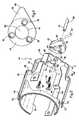
FIG. 1 is a fragmentary front vertical section of a combustion-powered fastener-driving tool incorporating the present cage and upper probe assembly;FIG. 2 is an exploded perspective view of the present cage and upper probe assembly with the tool shown fragmentarily; andFIG. 3 is a top plan view of the present probe.- Referring now to
FIG. 1 , a combustion-powered fastener-driving tool is generally designated 10 and includes amain housing 12 enclosing apower source 14. As is known in the art, thepower source 14 includes acylinder 16 defining a reciprocating pathway for apiston 18 to which is attached adriver blade 20. Thedriver blade 20 has atip 21 for engaging fasteners and driving them into a workpiece. Avalve sleeve 22 surrounds and axially reciprocates relative to thecylinder 16. Anupper portion 24 of the valve sleeve, thepiston 18 and acylinder head 26 combine to define acombustion chamber 28. - A
nosepiece 30 is secured to thepower source 14 and has aworkpiece end 32 opposite the power source and configured for being placed nearest a workpiece into which a fastener is to be driven. Aworkpiece contact element 34 is positioned at theworkpiece end 32 and slidingly reciprocates relative to thenosepiece 30 and is biased by a spring (not shown) to an extended position, seen inFIG. 1 . As is known in the art, theworkpiece contact element 34 has athreadable depth adjuster 36 for adjusting the depth of penetration of driven fasteners. Apusher rod 38 projects vertically relative to the depth adjuster 36 in a direction generally parallel to an operational axis of thedriver blade 20. Thepusher rod 38 moves in concert with theworkpiece contact element 34. - Referring now to
FIGs. 1 and2 , an upper orfree end 40 of thepusher rod 38 impacts anupper probe 42 of a cage and upper probe assembly, generally designated 44. Theassembly 44 includes theupper probe 42 and acage 46 including a plate-like base 48 and a plurality of generally normally extendingarms 50 configured for attachment to thevalve sleeve 22. - A feature of the
present assembly 44 is that theupper probe 42 is configured for direct attachment to thecage 46. Such attachment is achieved in the preferred embodiment by at least one and preferably threefastener apertures 52 on theupper probe 42 which are in registry with threefastener apertures 54 on thecage base 48, at least the latter preferably being countersunk. Corresponding threadedfasteners 56 secure theprobe 42 and thecage 46 together. Alternative fastening technologies are contemplated, including welding, chemical adhesives and other types of fasteners. Regardless of the type of fastening technology, theprobe 42 is attached to thecage 46 so that impact of thepusher rod 38 upon the probe is directly transmitted to the cage. - Referring now to
FIGs. 2 and 3 , theupper probe 42 is generally circular when viewed from above, and has at least onelobe formation 58 projecting radially from acenter 60 defined by the probe. Thelobe formation 58 is constructed and arranged for receiving and engaging theupper end 40 of thepusher rod 38. In the preferred embodiment, for reducing manufacturing cost and facilitating fit within thetool 10, thelobe formation 58 narrows with increasing distance from said center, or in other words is generally wedge-shaped when viewed from above (FIG. 3 ). Adistal end 62 of thelobe formation 58 is configured for engaging theupper end 40 of thepusher rod 38. Thelobe formation 58, and especially thedistal end 62 is sufficiently offset from an operational axis of the tool exemplified by the path of thedriver blade 20 so that the operation of thepusher rod 38 is remote from that of the driver blade. - The
upper probe 42 defines acentral aperture 64 configured for accommodating the driver blade 20 (best seen inFIG. 1 ). Also, thebase 48 defines athroughbore 66 in communication with, and preferably in registry with thecentral aperture 64 for receiving thedriver blade 20. To withstand repeated impact from thepusher rod 38 encountered through longterm use of thetool 10, theupper probe 42 is axially thickened relative to thebase 48. The relative thickening of theupper probe 42 is significant, and in the order of five times a thickness 'T' of the base. In one preferred embodiment, and for purposes of example only, the base thickness 'T' is approximately 1.524 mm (0.060 inch) and a probe thickness 'PT' is approximately 7.950 mm (0.313 inch). Other relative dimensions are contemplated depending on the application. Also, it is contemplated that thelobe formation 58 has a thickness less than the probe thickness PT. - Referring now to
FIG. 2 , thecage 46 has fourarms 50 projecting from thebase 48, each arm having aradially extending shoulder 68 and adistal eyelet 70 located at aneyelet end 72 for attachment to thevalve sleeve 22. Theshoulders 68 are provided to allow thearms 50 to clear internal components of thetool 10. As is known in the art, thearms 50 are provided in a sufficient length to permit thevalve sleeve 22 to reciprocate from an open position shown inFIG. 1 to a closed position in which thecombustion chamber 28 is sealed. - It will be seen that the present cage and
upper probe assembly 44 addresses the drawbacks of the prior art configurations. Motion from thepusher rod 38 is directly transmitted through theprobe 42 to thecage 46 and ultimately to thevalve sleeve 22. Also, the probe thickness PT is sufficient to withstand the operational impact of thepusher rod 38 over the operational life of thetool 10. - While a particular embodiment of the present cage and upper probe assembly for a fastener-driving tool has been described herein, it will be appreciated by those skilled in the art that changes and modifications may be made thereto without departing from the invention in its broader aspects and as set forth in the following claims.
Claims (12)
- A cage and upper probe assembly (66) for use in a fastener-driving tool (10) comprising a driver blade (20) a nosepiece (30) configured for slidably receiving said driver blade; a workpiece contact element (34) reciprocating relative to said nosepiece and a pusher rod (28) secured to said workpiece contact element for common movement; said cage and upper probe assembly comprising:a cage (46) including a base (48) and a plurality of arms (50) configured for attachment to a valve sleeve (22);a probe (42) configured for direct attachment to said cage and having at least one lobe formation (58); andsaid probe being attached to said cage so that impact of a pusher rod (38) upon said probe is directly transmitted to said cage,characterized in that said at least one lobe formation (58) is constructed and arranged for receiving an impact form said pusher rod (38).
- The probe assembly (44) of claim 1 wherein said probe (42) is generally circular when viewed from above, and said at least one lobe (58) projects radially from a center of said probe.
- The probe assembly (44) of claim 2 wherein said lobe (58) narrows with increasing distance from said center.
- The probe assembly (44) of claim 2 or claim 3 wherein said lobe (58) is generally wedge-shaped when viewed from above.
- The probe assembly (44) of any of claims 2 to 4 wherein said probe (42) defines a central aperture (64) configured for accommodating a driver blade (20).
- The probe assembly (44) of claim 5 wherein said base (48) defines a throughbore (66) in communication with said central aperture (64).
- The probe assembly (44) of any preceding claim wherein said probe (42) is axially thickened relative to said base (48).
- The probe assembly (44) of claim 7 wherein said probe (42) has an axial thickness approximately five times a thickness of said base (48).
- The probe assembly (44) of any preceding claim wherein said cage (46) has four arms (50) projecting from said base (48), each said arm having a radially extending shoulder (68) and a distal eyelet (70) for attachment to a valve sleeve (22).
- The probe assembly (44) of any preceding claim wherein said probe (42) is constructed and arranged so that said lobe (58) has a distal end (62) and engages the pusher rod (38) at said distal end (40).
- The probe assembly (44) of any preceding claim wherein said probe (42) and said base (48) have corresponding fastener apertures (52,54) for receiving threaded fasteners (56) used to join said probe to said base.
- A combustion-powered fastener-driving tool (10), comprising:a driver blade (20);a nosepiece (30) configured for slidably receiving said driver blade;a workpiece contact element (34) reciprocating relative to said nosepiece;a pusher rod (28) secured to said workpiece contact element for common movement; anda cage and upper probe assembly (44) according to any preceding claim.
Applications Claiming Priority (2)
| Application Number | Priority Date | Filing Date | Title |
|---|---|---|---|
| US10/931,351US7097083B2 (en) | 2004-09-01 | 2004-09-01 | Cage and offset upper probe assembly for fastener-driving tool |
| PCT/IB2005/052810WO2006025009A1 (en) | 2004-09-01 | 2005-08-26 | Cage and offset upper probe assembly for fastener-driving tool |
Publications (2)
| Publication Number | Publication Date |
|---|---|
| EP1807245A1 EP1807245A1 (en) | 2007-07-18 |
| EP1807245B1true EP1807245B1 (en) | 2009-04-15 |
Family
ID=35219601
Family Applications (1)
| Application Number | Title | Priority Date | Filing Date |
|---|---|---|---|
| EP05776701AExpired - LifetimeEP1807245B1 (en) | 2004-09-01 | 2005-08-26 | Cage and offset upper probe assembly for fastener-driving tool |
Country Status (9)
| Country | Link |
|---|---|
| US (1) | US7097083B2 (en) |
| EP (1) | EP1807245B1 (en) |
| JP (1) | JP5059610B2 (en) |
| KR (1) | KR20070044503A (en) |
| CN (1) | CN100551631C (en) |
| AU (1) | AU2005278792B2 (en) |
| CA (1) | CA2578916C (en) |
| DE (1) | DE602005013996D1 (en) |
| WO (1) | WO2006025009A1 (en) |
Families Citing this family (7)
| Publication number | Priority date | Publication date | Assignee | Title |
|---|---|---|---|---|
| JP4622437B2 (en)* | 2004-10-08 | 2011-02-02 | マックス株式会社 | Driving depth adjusting device for combustion gas driven nailer |
| US8152038B2 (en)* | 2007-03-16 | 2012-04-10 | Illinois Tool Works Inc. | Nose assembly for a fastener driving tool |
| US8220686B2 (en)* | 2007-07-17 | 2012-07-17 | Illinois Tool Works Inc. | Actuator pin guide for a fastener driving tool |
| TWI361128B (en)* | 2009-03-18 | 2012-04-01 | Basso Ind Corp | A demountable safety device of a power tool |
| KR200461017Y1 (en)* | 2009-03-27 | 2012-06-15 | 선 그레이스 홀딩스 리미티드 | Apparatus for shooting a nail |
| CN201389838Y (en) | 2009-03-27 | 2010-01-27 | 张汉勤 | Nail shooting device |
| CN104144770A (en)* | 2011-10-13 | 2014-11-12 | 多系统私人有限公司 | Hand held power tool for driving fasteners |
Family Cites Families (13)
| Publication number | Priority date | Publication date | Assignee | Title |
|---|---|---|---|---|
| US4403722A (en)* | 1981-01-22 | 1983-09-13 | Signode Corporation | Combustion gas powered fastener driving tool |
| US4483474A (en)* | 1981-01-22 | 1984-11-20 | Signode Corporation | Combustion gas-powered fastener driving tool |
| IN157475B (en)* | 1981-01-22 | 1986-04-05 | Signode Corp | |
| US5197646A (en)* | 1992-03-09 | 1993-03-30 | Illinois Tool Works Inc. | Combustion-powered tool assembly |
| US5558264A (en)* | 1995-02-13 | 1996-09-24 | Illinois Tool Works Inc. | Combustion-powered, fastener-driving tool with gas-actuated, fastener-feeding mechanism |
| JPH08290370A (en) | 1995-04-19 | 1996-11-05 | Japan Power Fastening Co Ltd | Gas combustion-type portable driving tool |
| US6123241A (en)* | 1995-05-23 | 2000-09-26 | Applied Tool Development Corporation | Internal combustion powered tool |
| US6145724A (en)* | 1997-10-31 | 2000-11-14 | Illinois Tool Works, Inc. | Combustion powered tool with combustion chamber delay |
| US5909836A (en)* | 1997-10-31 | 1999-06-08 | Illinois Tool Works Inc. | Combustion powered tool with combustion chamber lockout |
| FR2774017B1 (en)* | 1998-01-27 | 2000-03-17 | Spit Soc Prospect Inv Techn | COMPRESSED GAS-PISTON FIXING APPARATUS |
| JP2001170874A (en)* | 1999-12-16 | 2001-06-26 | Japan Power Fastening Co Ltd | Safety device for hand-held driving tools |
| US20030034377A1 (en) | 2001-08-16 | 2003-02-20 | Porth Chris H. | Combustion tool with coil magazine |
| US6959850B2 (en)* | 2004-02-27 | 2005-11-01 | Illinois Tool Works Inc. | Tool-less depth adjustment for fastener-driving tool |
- 2004
- 2004-09-01USUS10/931,351patent/US7097083B2/ennot_activeExpired - Lifetime
- 2005
- 2005-08-26KRKR1020077007007Apatent/KR20070044503A/ennot_activeCeased
- 2005-08-26WOPCT/IB2005/052810patent/WO2006025009A1/enactiveApplication Filing
- 2005-08-26DEDE602005013996Tpatent/DE602005013996D1/ennot_activeExpired - Lifetime
- 2005-08-26JPJP2007529109Apatent/JP5059610B2/ennot_activeExpired - Fee Related
- 2005-08-26CACA2578916Apatent/CA2578916C/ennot_activeExpired - Lifetime
- 2005-08-26EPEP05776701Apatent/EP1807245B1/ennot_activeExpired - Lifetime
- 2005-08-26CNCNB2005800317631Apatent/CN100551631C/ennot_activeExpired - Fee Related
- 2005-08-26AUAU2005278792Apatent/AU2005278792B2/ennot_activeExpired
Also Published As
| Publication number | Publication date |
|---|---|
| CN100551631C (en) | 2009-10-21 |
| AU2005278792A1 (en) | 2006-03-09 |
| JP2008511456A (en) | 2008-04-17 |
| EP1807245A1 (en) | 2007-07-18 |
| CA2578916A1 (en) | 2006-03-09 |
| US20060043139A1 (en) | 2006-03-02 |
| AU2005278792B2 (en) | 2009-03-05 |
| US7097083B2 (en) | 2006-08-29 |
| WO2006025009A1 (en) | 2006-03-09 |
| DE602005013996D1 (en) | 2009-05-28 |
| KR20070044503A (en) | 2007-04-27 |
| CA2578916C (en) | 2010-08-03 |
| JP5059610B2 (en) | 2012-10-24 |
| CN101022922A (en) | 2007-08-22 |
Similar Documents
| Publication | Publication Date | Title |
|---|---|---|
| EP2340153B1 (en) | Combustion power source with back pressure release for combustion powered fastener-driving tool | |
| EP2750832B1 (en) | Combustion tool | |
| KR101473351B1 (en) | A nosepiece of a fastener-driving tool equipped with a fastener magazine | |
| AU714594B1 (en) | Nosepiece shield for combustion powered tool | |
| AU2006311558A1 (en) | Combustion nailer workpiece contact element with enhanced gripping | |
| AU2006315949B2 (en) | Motor control for combustion nailer based on operating mode | |
| EP1807245B1 (en) | Cage and offset upper probe assembly for fastener-driving tool | |
| US6671163B2 (en) | Integrated spark and switch unit for combustion fastener driving tool | |
| EP1784286B1 (en) | Driver blade with auxiliary combustion chamber for combustion powered fastener-driving tool | |
| JP3677193B2 (en) | Tools with combustion power | |
| AU2009292089B9 (en) | Combustion power source with back pressure release for combustion powered fastener-driving tool | |
| NZ621620B2 (en) | High efficiency engine for combustion nailer |
Legal Events
| Date | Code | Title | Description |
|---|---|---|---|
| PUAI | Public reference made under article 153(3) epc to a published international application that has entered the european phase | Free format text:ORIGINAL CODE: 0009012 | |
| 17P | Request for examination filed | Effective date:20070322 | |
| AK | Designated contracting states | Kind code of ref document:A1 Designated state(s):DE FR GB | |
| RBV | Designated contracting states (corrected) | Designated state(s):DE FR GB | |
| DAX | Request for extension of the european patent (deleted) | ||
| 17Q | First examination report despatched | Effective date:20071221 | |
| GRAP | Despatch of communication of intention to grant a patent | Free format text:ORIGINAL CODE: EPIDOSNIGR1 | |
| GRAP | Despatch of communication of intention to grant a patent | Free format text:ORIGINAL CODE: EPIDOSNIGR1 | |
| GRAS | Grant fee paid | Free format text:ORIGINAL CODE: EPIDOSNIGR3 | |
| GRAA | (expected) grant | Free format text:ORIGINAL CODE: 0009210 | |
| AK | Designated contracting states | Kind code of ref document:B1 Designated state(s):DE FR GB | |
| REG | Reference to a national code | Ref country code:GB Ref legal event code:FG4D | |
| REF | Corresponds to: | Ref document number:602005013996 Country of ref document:DE Date of ref document:20090528 Kind code of ref document:P | |
| PLBE | No opposition filed within time limit | Free format text:ORIGINAL CODE: 0009261 | |
| STAA | Information on the status of an ep patent application or granted ep patent | Free format text:STATUS: NO OPPOSITION FILED WITHIN TIME LIMIT | |
| 26N | No opposition filed | Effective date:20100118 | |
| REG | Reference to a national code | Ref country code:FR Ref legal event code:PLFP Year of fee payment:11 | |
| PGFP | Annual fee paid to national office [announced via postgrant information from national office to epo] | Ref country code:GB Payment date:20150827 Year of fee payment:11 Ref country code:DE Payment date:20150827 Year of fee payment:11 | |
| PGFP | Annual fee paid to national office [announced via postgrant information from national office to epo] | Ref country code:FR Payment date:20150817 Year of fee payment:11 | |
| REG | Reference to a national code | Ref country code:DE Ref legal event code:R119 Ref document number:602005013996 Country of ref document:DE | |
| GBPC | Gb: european patent ceased through non-payment of renewal fee | Effective date:20160826 | |
| REG | Reference to a national code | Ref country code:FR Ref legal event code:ST Effective date:20170428 | |
| PG25 | Lapsed in a contracting state [announced via postgrant information from national office to epo] | Ref country code:DE Free format text:LAPSE BECAUSE OF NON-PAYMENT OF DUE FEES Effective date:20170301 Ref country code:GB Free format text:LAPSE BECAUSE OF NON-PAYMENT OF DUE FEES Effective date:20160826 Ref country code:FR Free format text:LAPSE BECAUSE OF NON-PAYMENT OF DUE FEES Effective date:20160831 |