EP1806783B1 - Improved interdigitated capacitive structure for an integrated circuit - Google Patents
Improved interdigitated capacitive structure for an integrated circuitDownload PDFInfo
- Publication number
- EP1806783B1 EP1806783B1EP06013378AEP06013378AEP1806783B1EP 1806783 B1EP1806783 B1EP 1806783B1EP 06013378 AEP06013378 AEP 06013378AEP 06013378 AEP06013378 AEP 06013378AEP 1806783 B1EP1806783 B1EP 1806783B1
- Authority
- EP
- European Patent Office
- Prior art keywords
- polarity
- strip
- layer
- extension
- strips
- Prior art date
- Legal status (The legal status is an assumption and is not a legal conclusion. Google has not performed a legal analysis and makes no representation as to the accuracy of the status listed.)
- Active
Links
Images


Classifications
- H—ELECTRICITY
- H10—SEMICONDUCTOR DEVICES; ELECTRIC SOLID-STATE DEVICES NOT OTHERWISE PROVIDED FOR
- H10B—ELECTRONIC MEMORY DEVICES
- H10B12/00—Dynamic random access memory [DRAM] devices
- H—ELECTRICITY
- H01—ELECTRIC ELEMENTS
- H01L—SEMICONDUCTOR DEVICES NOT COVERED BY CLASS H10
- H01L23/00—Details of semiconductor or other solid state devices
- H01L23/52—Arrangements for conducting electric current within the device in operation from one component to another, i.e. interconnections, e.g. wires, lead frames
- H01L23/522—Arrangements for conducting electric current within the device in operation from one component to another, i.e. interconnections, e.g. wires, lead frames including external interconnections consisting of a multilayer structure of conductive and insulating layers inseparably formed on the semiconductor body
- H01L23/5222—Capacitive arrangements or effects of, or between wiring layers
- H01L23/5223—Capacitor integral with wiring layers
- H—ELECTRICITY
- H10—SEMICONDUCTOR DEVICES; ELECTRIC SOLID-STATE DEVICES NOT OTHERWISE PROVIDED FOR
- H10B—ELECTRONIC MEMORY DEVICES
- H10B99/00—Subject matter not provided for in other groups of this subclass
- H—ELECTRICITY
- H10—SEMICONDUCTOR DEVICES; ELECTRIC SOLID-STATE DEVICES NOT OTHERWISE PROVIDED FOR
- H10D—INORGANIC ELECTRIC SEMICONDUCTOR DEVICES
- H10D1/00—Resistors, capacitors or inductors
- H10D1/60—Capacitors
- H10D1/68—Capacitors having no potential barriers
- H10D1/692—Electrodes
- H—ELECTRICITY
- H01—ELECTRIC ELEMENTS
- H01L—SEMICONDUCTOR DEVICES NOT COVERED BY CLASS H10
- H01L2924/00—Indexing scheme for arrangements or methods for connecting or disconnecting semiconductor or solid-state bodies as covered by H01L24/00
- H01L2924/0001—Technical content checked by a classifier
- H01L2924/0002—Not covered by any one of groups H01L24/00, H01L24/00 and H01L2224/00
Definitions
- the present inventionrelates generally to capacitors for integrated circuits, and more particularly to system and method for an improved interdigitated capacitive structure for an integrated circuit.
- capacitorsare employed in integrated circuits to perform a variety of functions. Capacitors can be used to construct band pass filters, phase locked loops (PLLs), dynamic random access memory (DRAM) components, and a host of other useful devices. In some instances, some common elements of an integrated circuit exhibit inherent capacitance.
- PLLsphase locked loops
- DRAMdynamic random access memory
- certain active integrated circuit elementssuch as, for example, bipolar and metal-oxide-semiconductor (MOS) transistors, contain electrical junctions that exhibit capacitance.
- MOSmetal-oxide-semiconductor
- a depletion region of an electrical junctioncan be described as functionally equivalent to a small parallel-plate capacitor.
- Such a capacitorcan be modeled as a fixed-value capacitor, or as a variable capacitor, with a capacitance that changes as a function of the voltage applied to the junction.
- certain passive integrated circuit elementssuch as, for example, polycrystalline silicon (polysilicon) and metal lines, also have inherent capacitance with respect to each other and to any other conductors.
- MIMmetal-insulator-metal
- MOM capacitorsconsist of strips of conductive material of opposite polarity separated by dielectric material. MOM capacitors can often take advantage of existing process steps. For example, the dual-damascene techniques typically used with copper multilevel interconnection metallization on integrated circuits can be used to construct stacks of copper-filled vias and trenches. Two or more such copper-filled vias or trenches, separated by oxide dielectrics, can form a MOM capacitor. MOM capacitors offer greater capacitance per unit area than traditional capacitors, with an efficient form. However, MOM capacitors also typically require a complex design, which can overcome benefits gained by taking advantage of standard semiconductor device manufacture process steps.
- Some modem methodsemploy both MOM and MIM capacitors: However, typically these capacitors, when combined, are formed on separate layers of an integrated circuit, with a MIM capacitor layer stacked above a MOM capacitor layer. Thus, while the capacitance is increased, the vertical chip area required is also increased, which can also add complexity to the design and manufacturing process.
- MOM capacitorsare formed with vertical stacks of MOM layers. While these stacked MOM capacitors can offer increased capacitance, however, mismatches in alignment between layers can cause uncertainty in the manufacturing process and performance degradation. At the very least, where the stacks are not aligned the actual capacitance deviates from the expected capacitance, which can cause other devices that depend on the capacitor to behave unpredictably, cascading through the chip.
- a first layer of the interdigitated capacitorcomprises substantially parallel strips alternately connected to a first L-shaped bus and a second L-shaped bus.
- a second layer of the interdigitated capacitoralso comprises substantially parallel strips alternately connected to a first L-shaped bus and a second L-shaped bus.
- strips of the second layerare oriented approximately perpendicular to the strips of the first layer.
- the first bus of the first layerconnects to the first bus of the second layer and the second bus of the first layer connects to the second bus of the second layer through vias.
- a dielectric materialis formed between the strips of the same and different layers.
- the layers of parallel strips of the interdigitated capacitorcould be stacked by means of further vias.
- WO 01/99163 A2describes a multilayer pillar array capacitor structure.
- a multilayer pillar array capacitor structurecomprises a two-directional parallel array of electrically conductive, vertical pillars sandwiched between top and bottom parallel inline arrays of electrically conductive horizontal plates.
- the vertical pillars and the horizontal platesoperate as electrodes for the multilayer pillar array capacitor.
- the vertical pillars and the horizontal platesare constructed over a substrate of semiconductor material in a multiple conductor level process having five levels being intersected by dielectric layers.
- each level of a vertical pillarhas a different polarity, wherein the sequence of polarity in a neighboring pillar is alternated, thus, a cross-over type capacitance between each other and parallel plate type capacitance between the horizontal plates is generated.
- EP 1 398 834 A2describes an electronic device having a voltage supply and a method of manufacturing the same.
- the electronic devicecomprises a semiconductor chip having two upper metallization layers which include voltage supply structures, having isolation layers disposed in-between and vias for connection to module areas of an integrated circuit.
- the voltage supply structurehas a layer of supply lines being aligned in parallel, wherein a further layer of a subsequent metallization layer has a alignment structure being perpendicular to the precedent metallization layer.
- US2003/0092259 A1describes a method to fabricate MIM capacitor structures using a damascene process.
- a metal-insulator-metal capacitoris formed in a damascene process.
- the capacitorhas a substrate of inter-metal dielectric, in which copper electrodes and copper interconnects are formed via a damascene or or dual damascene process. Gaps between the electrode plates comprise low-k dielectrical material.
- small copper electrode platesare electrically connected by metal regions.
- a high-k dielectric materialresides between the copper electrode plates, wherein the high-k dielectric overlaps the bottom and top copper electrode plates.
- the top and bottom copper electrode platesmay be formed in pairs, wherein each member of the pair has substantially the same size and shape of the other.
- a method for fabricating a capacitor structurecomprises forming a first layer of a sequence of substantially parallel interdigitated strips, each strip of either a first polarity or a second polarity, the sequence alternating between a strip of the first polarity and a strip of the second polarity.
- a first dielectric layeris deposited over each strip of the first layer of strips.
- a first extension layer of a sequence of substantially interdigitated extension stripsis formed over the first dielectric layer, each extension strip of either the first polarity or the second polarity, the sequence alternating between an extension strip of the first polarity and an extension strip of the second polarity, each extension strip deposited over a strip of the first layer of the opposite polarity and parallel thereto.
- a first sequence of viasis formed over the first extension layer, each via of either the first polarity or the second polarity, the sequence alternating between a via of the first polarity and a via of the second polarity, each via deposited over an extension strip of the same polarity.
- a second layer of a sequence of substantially parallel interdigitated stripsis formed over the first sequence of vias, each strip of either the first polarity or the second polarity, each strip deposited over a via of the same polarity.
- a capacitor structure for an integrated circuitcomprises a first layer of a sequence of substantially parallel interdigitated strips, each strip of either a first polarity or a second polarity, the sequence alternating between a strip of the first polarity and a strip of the second polarity.
- a first dielectric layeris deposited over each strip of the first layer of strips.
- a first extension layer of a sequence of substantially interdigitated extension stripsis deposited over the first dielectric layer, each extension strip of either the first polarity or the second polarity, the sequence alternating between an extension strip of the first polarity and an extension strip of the second polarity, each extension strip deposited over a strip of the first layer of the opposite polarity and parallel thereto.
- a first sequence of viasis coupled to the first extension layer, each via of either the first polarity or the second polarity, the sequence alternating between a via of the first polarity and a via of the second polarity, each via deposited over an extension strip of the same polarity.
- a second layer of a sequence of substantially parallel interdigitated stripsis coupled to the first sequence of vias, each strip of either the first polarity or the second polarity, each strip deposited over a via of the same polarity.
- An advantage of the present inventionis efficiently combining MOM and MIM-type capacitors.
- the layers of substantially parallel interdigitated stripscan be configured similarly to existing MOM capacitors.
- the first dielectric layer and the first extension layeradd MIM-type capacitance to the first layer of interdigitated strips.
- the MIM-type capacitoris sandwiched between layers of MOM capacitors, connected through vias.
- a further advantage of the present inventionis reducing vertical chip area required for a desired capacitance per unit area.
- the addition of MIM-type capacitance between layers of a MOM capacitoradds surface area and extends the capacitive effect of one layer of MOM capacitor strips on the layer below it, between strips on the same layer, and between adjacent vias. Accordingly, the effective capacitance per unit area is increased, without additional process steps or expanding the vertical chip area required for a MOM capacitor.
- Yet another advantage of the present inventionis improving mismatch performance.
- the addition of MIM-type capacitance between layers, coupled through vias to a layer above the MIM-type layeradds structural support that can offset mismatches in alignment between MOM capacitor strips. Further, the expanded capacitive field of the MIM-type layer and the associated vias improves the capacitive performance in the presence of mismatches in alignment between MOM capacitor strips.
- Figure 1is a schematic cross sectional view illustrating features of a preferred embodiment of a capacitive structure for an integrated circuit
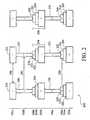
- Figure 2is a side view illustrating features of a preferred embodiment of a capacitive structure for an integrated circuit
- Figures 3 and 4are schematic cross-sectional views illustrating features of a , capacitive structure for an integrated circuit in accordance with other embodiments of the present invention.
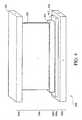
- FIGS. 5A through 5Lillustrate the steps of forming a capacitive structure for an integrated circuit, in accordance with one embodiment of the present invention.
- the present inventionwill be described with respect to preferred embodiments in a specific context, namely an improved interdigitated capacitive structure for an integrated circuit.
- the inventionmay also be applied, however, to other capacitive structures, such as, for example, standard MOM capacitors, multi-level MOM capacitors, standard MIM capacitors, and other suitable capacitive structures, as one skilled in the art will understand.
- capacitor 100includes a layer 102 of substantially parallel interdigitated capacitive strips 110, 112, 114, and 116.
- Each capacitive stripis of either a first polarity or a second polarity, indicated by either a "plus” sign (+) or a "minus” sign (-):
- the capacitive stripsare interdigitated, with alternating polarities. Accordingly, strip 110 is of positive polarity, strip 112 is of negative polarity, strip 114 is of positive polarity, and strip 116 is of negative polarity.
- the plurality of conductive stripsform a first layer of a MOM-type capacitive structure.
- four conductive stripsare shown.
- any number of conductive strips, and the structures formed above each strip,can also be employed.
- a layer 104 of dielectric materialis disposed on top of the layer 102. As illustrated, layer 104 is comprised of strips of dielectric material 120, 122, 124, and 126 deposited on top of each strip. As shown, each strip of dielectric material is thinner than the capacitive strip of layer 102 to which it is coupled. Furthermore, one skilled in the art will understand that a dielectric material (not shown) can be employed to separate the other structures as described below.
- a layer 106 of extension strips 130, 132, 134, and 136is disposed on top of the layer 104.
- Each extension stripis of either a first or second polarity and is of the opposite polarity than the conductive strip directly below it.
- extension strip 130is of negative polarity and capacitive strip 110 is of positive polarity.
- extension strip 132is of positive polarity and capacitive strip 112 is of negative polarity.
- the layer 106is coupled to another layer of capacitive strips above (not shown) through a layer 108 of vias.
- Each viais of either a first or second polarity and is of the same polarity as the extension strip to which it is coupled.
- extension strip 130is of negative polarity and vias 140, 142, 144, and 146 are also of negative polarity.
- extension strip 132is of positive polarity and vias 150, 152, 154, and 156 are also of positive polarity.
- extension strip 134is of negative polarity, and vias 160, 162. 164, and 166 are also of negative polarity.
- extension strip 136is of positive polarity, and vias 160, 162 , 164, and 166 are also of positive polarity.
- a second capacitor 100can be stacked on top of capacitor 100 for an additional layer of MOM/MIM-type capacitance.
- the layer 108 of viascouples to a layer 102 above it of the same polarity as the vias.
- the capacitive strip that couples to vias 140-146would be of negative polarity and the capacitive strip that couples to vias 150-156 would be of negative polarity.
- capacitor 200is configured with two stacks of capacitors 100, with a final top layer 102c above the top layer 108b.
- each layer 102is shown with three capacitive strips.
- layer 102ais shows with a negative polarity capacitive strip 202, a positive polarity capacitive strip 204, and a negative polarity capacitive strip 206.
- a negative polarity capacitive strip 202is shown with a negative polarity capacitive strip 202, a positive polarity capacitive strip 204, and a negative polarity capacitive strip 206.
- any number of conductive strips, and the structures formed above each stripcan also be employed.
- Layer 104ais shown with three dielectric strips 210, 212, and 214.
- Layer 106ais shown with three extension strips 220, 222, and 224.
- Each extension stripis of a polarity opposite that of the conductive strip directly below it.
- extension strip 220is of a positive polarity
- capacitive strip 202is of a negative polarity.
- Layer 108ais shown with three vias 230, 232, and 234. As described above, each via is of the same polarity as the extension strip to which it is coupled above and the capacitive strip to which it is coupled below. Thus, for example, via 230 is of the same (positive) polarity as extension strip 220 and capacitive strip 240.
- Capacitor 200thus illustrates the stacking of two or more capacitors 100.
- Layer 108ais coupled to a layer 102b above layer 108a.
- layer 108bis coupled to a layer 102c above layer 108b.
- the capacitors 100can be stacked in any number of iterations and configurations, adding or subtracting capacitors 100 to obtain an interdigitated capacitor with a predetermined number of layers to obtain a desired capacitance value.
- capacitor 200exhibits the improved capacitance of a MIM capacitor, with the reduced chip area of a MOM capacitor.
- capacitor 200exhibits a capacitance 298 between extension strip 220 and extension strip 222 of layer 106a.
- capacitance 298is highlighted as illustrative and should not be construed as the only capacitive interactions of capacitor 200.
- the capacitive strips, extension strips, and viascomprise a conductive material, including but not limited to copper, aluminum, titanium nitride (TiN), doped polysilicon, and any combinations thereof.
- a conductive materialincluding but not limited to copper, aluminum, titanium nitride (TiN), doped polysilicon, and any combinations thereof.
- the composition of one strip and/or viacan vary from that of another strip and/or via, and the composition of the capacitive strips, extension strips, and vias need not be identical.
- the dielectric stripscomprise a dielectric material, including but not limited to silicon dioxide (SiO 2 ), silicon nitride (SiN), tantalum pentoxide (Ta 5 O 2 ), and any combinations thereof.
- a dielectric materialincluding but not limited to silicon dioxide (SiO 2 ), silicon nitride (SiN), tantalum pentoxide (Ta 5 O 2 ), and any combinations thereof.
- the selection of conductive materials and dielectric materialsdepends, in part, on the manufacturing process and the application intended for the capacitive elements, as one skilled in the art will understand.
- the first layer 102acomprises a capacitive strip 310, as described above.
- the second layer 104acomprises a dielectric strip 312, as described above.
- the third layer 106acomprises an extension strip segmented into a plurality of blocks 320, 322, and 324. Each block is coupled to a via of layer 108a.
- block 320is coupled to via 330.
- the vias of layer 108aare coupled to a capacitive strip 340 (of the same polarity as the vias) of layer 102b. Therefore, capacitor 100 can be configured with block-type extension strips. Forming the extension strips as block-type segments can simplify the manufacturing process, as one skilled in the art will understand.
- the first layer 102acomprises a capacitive strip 410, as described above.
- the second layer 104acomprises a dielectric strip 412, as described above.
- the third layer 106acomprises an extension strip 420, as described above.
- the fourth layer 108acomprises a horizontally continuous via configured as a substantially vertical trench-type via 430, as opposed to the plurality of columns shown in Figures 1-3 for the vias.
- the continuous via 430 of layer 108ais coupled to a capacitive strip 440 (of the same polarity) of layer 102b. Therefore, capacitor 100 can be configured with vertical trench-type vias. Forming the vias as vertical trench-type vias can simplify the manufacturing process, as one skilled in the art will understand.
- FIG. 5A-5Lthere is shown a method of fabricating an improved interdigitated capacitive structure such as structure shown in Figure 2 .
- the process shownis limited to two adjacent conductive strips and the features formed above them.
- One skilled in the artwill understand that other features and devices can also be formed concurrently with the features as described below.
- a metal layer 520is deposited on an isolation layer 510 by, for example, chemical vapor deposition (CVP), physical vapor deposition (PVD), or other suitable method.
- CVPchemical vapor deposition
- PVDphysical vapor deposition
- a layer of antireflective coatingcan be deposited over the metal layer 520.
- a layer of photoresist 530is then formed over the metal layer 520.
- the photoresistis then exposed through a mask (not shown) with a pattern including conductive strips and other circuit elements.
- the patternis developed on the photoresist, which is subsequently removed to expose strips 532 and 534, as shown in Figure 5B .
- the uncovered area of metal layer 520is then etched away and the remaining photoresist is removed, as one skilled in the art will understand.
- conductive strips 522 and 524remain as shown in Figure 5C .
- IMDinter-metal dielectric
- CMPchemical mechanical polishing
- Another layer of photoresist 560is formed over IMD 550. Following another exposure and development process, photoresist on the areas where dielectric strips are located is removed and holes 562 and 564 are left, as shown in Figure 5E .
- dielectric strips 552 and 554are formed, as shown in Figure 5F .
- dielectric strips 552 and 554can be formed from the same inter-metal dielectric that comprises IMD 550, in which case the holes etched into IMD 550 stop above the surface of the underlying features (i.e., conductive strips 522 and 524), forming an appropriate shape as desired.
- photoresist 570 on the areas where extension strips are locatedis removed and holes 572 and 574 are left, as shown in Figure 5G .
- a conductive materialis deposited and extension strips 582 and 584 are formed, as shown in Figure 5H .
- ILD 590is formed over the remaining structures, as shown in Figure 5I .
- ILD 590can be formed from the same dielectric material as IMD 550.
- the upper surface of ILD 590can also be planarized by any of a number of methods known to one skilled in the art.
- Another layer of photoresist 600is formed over ILD 590. Following an exposure and development process, photoresist on the area where vias are located is removed and holes 602 and 604 are left. After etching down to the surface of the underlying features (i.e., extension strips 582 and 584), vias 592 and 594 are formed, as shown in Figure 5J .
- an improved interdigitated capacitive structure for an integrated circuitis formed.
- One skilled in the artwill understand that the above process can be repeated to form another capacitive unit on top of IMD 620, with conductive strips 622 and 624 forming a layer 102 for the structure above.
Landscapes
- Engineering & Computer Science (AREA)
- Power Engineering (AREA)
- Physics & Mathematics (AREA)
- Condensed Matter Physics & Semiconductors (AREA)
- General Physics & Mathematics (AREA)
- Computer Hardware Design (AREA)
- Microelectronics & Electronic Packaging (AREA)
- Semiconductor Integrated Circuits (AREA)
Description
- The present invention relates generally to capacitors for integrated circuits, and more particularly to system and method for an improved interdigitated capacitive structure for an integrated circuit.
- Generally, capacitors are employed in integrated circuits to perform a variety of functions. Capacitors can be used to construct band pass filters, phase locked loops (PLLs), dynamic random access memory (DRAM) components, and a host of other useful devices. In some instances, some common elements of an integrated circuit exhibit inherent capacitance.
- For example, certain active integrated circuit elements, such as, for example, bipolar and metal-oxide-semiconductor (MOS) transistors, contain electrical junctions that exhibit capacitance. In fact, depending on the particular type of transistor, a depletion region of an electrical junction can be described as functionally equivalent to a small parallel-plate capacitor. Such a capacitor can be modeled as a fixed-value capacitor, or as a variable capacitor, with a capacitance that changes as a function of the voltage applied to the junction. Furthermore, certain passive integrated circuit elements, such as, for example, polycrystalline silicon (polysilicon) and metal lines, also have inherent capacitance with respect to each other and to any other conductors.
- One disadvantage, however, in employing such inherent capacitance to achieve certain functionality, is that the inherent capacitance is often insufficient and difficult to engineer. For example, because this inherent capacitance is typically a byproduct of some other functionality for which the particular element is designed, the inherent capacitance cannot be a higher design priority than the primary functionality. Moreover, because inherent capacitance is tied to a particular element, the capacitive effect is tied to that element's location in a circuit and cannot be relocated. Thus, integrated circuits often employ dedicated capacitors as circuit elements in their own right.
- Traditional capacitors are two conductive materials separated by a dielectric. In integrated circuits, the two conductive materials are often flat plates with an intervening layer of dielectric material. One significant disadvantage of this approach, however, is that a relatively large area of the integrated circuit chip is typically required to achieve the desired capacitance.
- One structure employed to increase capacitance is a metal-insulator-metal (MIM) capacitor. In its simplest configuration, a number of horizontal parallel plates of metal are stacked into several layers, separated by dielectrics. The plates are conductive and alternately coupled to form opposite electrodes of a capacitor. The vertical stack of plates is simple to construct, and offers more capacitance per unit area than two conductive surfaces alone. However, while simple to construct, forming a MIM capacitor with many layers often requires additional processing steps, which can add prohibitive cost to the manufacturing process.
- Another structure employed to increase capacitance is a metal-oxide-metal (MOM) capacitor. Generally, MOM capacitors consist of strips of conductive material of opposite polarity separated by dielectric material. MOM capacitors can often take advantage of existing process steps. For example, the dual-damascene techniques typically used with copper multilevel interconnection metallization on integrated circuits can be used to construct stacks of copper-filled vias and trenches. Two or more such copper-filled vias or trenches, separated by oxide dielectrics, can form a MOM capacitor. MOM capacitors offer greater capacitance per unit area than traditional capacitors, with an efficient form. However, MOM capacitors also typically require a complex design, which can overcome benefits gained by taking advantage of standard semiconductor device manufacture process steps.
- Some modem methods employ both MOM and MIM capacitors: However, typically these capacitors, when combined, are formed on separate layers of an integrated circuit, with a MIM capacitor layer stacked above a MOM capacitor layer. Thus, while the capacitance is increased, the vertical chip area required is also increased, which can also add complexity to the design and manufacturing process.
- Furthermore, some MOM capacitors are formed with vertical stacks of MOM layers. While these stacked MOM capacitors can offer increased capacitance, however, mismatches in alignment between layers can cause uncertainty in the manufacturing process and performance degradation. At the very least, where the stacks are not aligned the actual capacitance deviates from the expected capacitance, which can cause other devices that depend on the capacitor to behave unpredictably, cascading through the chip.
- Therefore, there is a need for a system and/or method for forming improved integrated circuit capacitors that overcomes at least some of the disadvantages associated with previous systems and methods.
US 2004/0174655 A1 describes an interdigitated capacitor structure for an integrated circuit. Herein, a first layer of the interdigitated capacitor comprises substantially parallel strips alternately connected to a first L-shaped bus and a second L-shaped bus. A second layer of the interdigitated capacitor also comprises substantially parallel strips alternately connected to a first L-shaped bus and a second L-shaped bus. Herein, strips of the second layer are oriented approximately perpendicular to the strips of the first layer. The first bus of the first layer connects to the first bus of the second layer and the second bus of the first layer connects to the second bus of the second layer through vias. A dielectric material is formed between the strips of the same and different layers. The layers of parallel strips of the interdigitated capacitor could be stacked by means of further vias.WO 01/99163 A2 EP 1 398 834 A2 describes an electronic device having a voltage supply and a method of manufacturing the same. Herein, the electronic device comprises a semiconductor chip having two upper metallization layers which include voltage supply structures, having isolation layers disposed in-between and vias for connection to module areas of an integrated circuit. The voltage supply structure has a layer of supply lines being aligned in parallel, wherein a further layer of a subsequent metallization layer has a alignment structure being perpendicular to the precedent metallization layer.US2003/0092259 A1 describes a method to fabricate MIM capacitor structures using a damascene process. Herein, a metal-insulator-metal capacitor is formed in a damascene process. The capacitor has a substrate of inter-metal dielectric, in which copper electrodes and copper interconnects are formed via a damascene or or dual damascene process. Gaps between the electrode plates comprise low-k dielectrical material. In addition, small copper electrode plates are electrically connected by metal regions. A high-k dielectric material resides between the copper electrode plates, wherein the high-k dielectric overlaps the bottom and top copper electrode plates. The top and bottom copper electrode plates may be formed in pairs, wherein each member of the pair has substantially the same size and shape of the other.- It is an object of the present invention to provide a system for and a method for fabricating an improved interdigitated capacitive structure for an integrated circuit.
- This object is solved by a capacitor structure according to claim 1 and a method for fabricating the same according to claim 8. Further advantages, refinements and embodiments of the invention are described in the respective sub-claims.
- Herein, a method for fabricating a capacitor structure comprises forming a first layer of a sequence of substantially parallel interdigitated strips, each strip of either a first polarity or a second polarity, the sequence alternating between a strip of the first polarity and a strip of the second polarity. A first dielectric layer is deposited over each strip of the first layer of strips. A first extension layer of a sequence of substantially interdigitated extension strips is formed over the first dielectric layer, each extension strip of either the first polarity or the second polarity, the sequence alternating between an extension strip of the first polarity and an extension strip of the second polarity, each extension strip deposited over a strip of the first layer of the opposite polarity and parallel thereto. A first sequence of vias is formed over the first extension layer, each via of either the first polarity or the second polarity, the sequence alternating between a via of the first polarity and a via of the second polarity, each via deposited over an extension strip of the same polarity. A second layer of a sequence of substantially parallel interdigitated strips is formed over the first sequence of vias, each strip of either the first polarity or the second polarity, each strip deposited over a via of the same polarity.
- Further, a capacitor structure for an integrated circuit comprises a first layer of a sequence of substantially parallel interdigitated strips, each strip of either a first polarity or a second polarity, the sequence alternating between a strip of the first polarity and a strip of the second polarity. A first dielectric layer is deposited over each strip of the first layer of strips. A first extension layer of a sequence of substantially interdigitated extension strips is deposited over the first dielectric layer, each extension strip of either the first polarity or the second polarity, the sequence alternating between an extension strip of the first polarity and an extension strip of the second polarity, each extension strip deposited over a strip of the first layer of the opposite polarity and parallel thereto. A first sequence of vias is coupled to the first extension layer, each via of either the first polarity or the second polarity, the sequence alternating between a via of the first polarity and a via of the second polarity, each via deposited over an extension strip of the same polarity. A second layer of a sequence of substantially parallel interdigitated strips is coupled to the first sequence of vias, each strip of either the first polarity or the second polarity, each strip deposited over a via of the same polarity.
- An advantage of the present invention is efficiently combining MOM and MIM-type capacitors. The layers of substantially parallel interdigitated strips can be configured similarly to existing MOM capacitors. The first dielectric layer and the first extension layer add MIM-type capacitance to the first layer of interdigitated strips. Thus, the MIM-type capacitor is sandwiched between layers of MOM capacitors, connected through vias.
- A further advantage of the present invention is reducing vertical chip area required for a desired capacitance per unit area. The addition of MIM-type capacitance between layers of a MOM capacitor adds surface area and extends the capacitive effect of one layer of MOM capacitor strips on the layer below it, between strips on the same layer, and between adjacent vias. Accordingly, the effective capacitance per unit area is increased, without additional process steps or expanding the vertical chip area required for a MOM capacitor.
- Yet another advantage of the present invention is improving mismatch performance. The addition of MIM-type capacitance between layers, coupled through vias to a layer above the MIM-type layer adds structural support that can offset mismatches in alignment between MOM capacitor strips. Further, the expanded capacitive field of the MIM-type layer and the associated vias improves the capacitive performance in the presence of mismatches in alignment between MOM capacitor strips.
- For a more complete understanding of the present invention, and the advantages thereof, reference is now made to the following descriptions taken in conjunction with the accompanying drawing, in which:
Figure 1 is a schematic cross sectional view illustrating features of a preferred embodiment of a capacitive structure for an integrated circuit;Figure 2 is a side view illustrating features of a preferred embodiment of a capacitive structure for an integrated circuit;Figures 3 and4 are schematic cross-sectional views illustrating features of a , capacitive structure for an integrated circuit in accordance with other embodiments of the present invention; andFigures 5A through 5L illustrate the steps of forming a capacitive structure for an integrated circuit, in accordance with one embodiment of the present invention.- The making and using of the presently preferred embodiments are discussed in detail below. It should be appreciated, however, that the present invention provides many applicable inventive concepts that can be embodied in a wide variety of specific contexts. The specific embodiments discussed are merely illustrative of specific ways to make and use the invention, and do not limit the scope of the invention.
- The present invention will be described with respect to preferred embodiments in a specific context, namely an improved interdigitated capacitive structure for an integrated circuit. The invention may also be applied, however, to other capacitive structures, such as, for example, standard MOM capacitors, multi-level MOM capacitors, standard MIM capacitors, and other suitable capacitive structures, as one skilled in the art will understand.
- With reference now to
Figure 1 , there is shown a schematic cross sectional view of a capacitive structure for an integrated circuit, generally indicated byreference numeral 100. As illustrated,capacitor 100 includes alayer 102 of substantially parallel interdigitatedcapacitive strips strip 110 is of positive polarity,strip 112 is of negative polarity,strip 114 is of positive polarity, andstrip 116 is of negative polarity. - One skilled in the art will understand that the plurality of conductive strips form a first layer of a MOM-type capacitive structure. In the illustrated embodiment, four conductive strips are shown. One skilled in the art will understand that any number of conductive strips, and the structures formed above each strip, can also be employed.
- A
layer 104 of dielectric material is disposed on top of thelayer 102. As illustrated,layer 104 is comprised of strips ofdielectric material layer 102 to which it is coupled. Furthermore, one skilled in the art will understand that a dielectric material (not shown) can be employed to separate the other structures as described below. - A
layer 106 of extension strips 130, 132, 134, and 136 is disposed on top of thelayer 104. Each extension strip is of either a first or second polarity and is of the opposite polarity than the conductive strip directly below it. For example,extension strip 130 is of negative polarity andcapacitive strip 110 is of positive polarity. Similarly,extension strip 132 is of positive polarity andcapacitive strip 112 is of negative polarity. One skilled in the art will understand that the combination of an extension strip, dielectric material, and underlying capacitive strip of opposite polarity form a MIM-type capacitive structure. - The
layer 106 is coupled to another layer of capacitive strips above (not shown) through alayer 108 of vias. Each via is of either a first or second polarity and is of the same polarity as the extension strip to which it is coupled. For example,extension strip 130 is of negative polarity andvias extension strip 132 is of positive polarity andvias extension strip 134 is of negative polarity, and vias 160, 162. 164, and 166 are also of negative polarity. Moreover,extension strip 136 is of positive polarity, and vias 160, 162,164, and 166 are also of positive polarity. - Together layers 102, 104, 106, and 108 make up a stackable capacitance unit. Thus, a
second capacitor 100 can be stacked on top ofcapacitor 100 for an additional layer of MOM/MIM-type capacitance. When thus stacked, thelayer 108 of vias couples to alayer 102 above it of the same polarity as the vias. For example, in asecond layer 102 stacked abovelayer 108, the capacitive strip that couples to vias 140-146 would be of negative polarity and the capacitive strip that couples to vias 150-156 would be of negative polarity. Further, in a preferred embodiment, there is a singleadditional layer 102 coupled to thelast layer 108 of a series of stackedcapacitors 100. - With reference now to
Figure 2 , there is shown a side view of a stacked capacitive structure for an integrated circuit, generally indicated byreference numeral 200. As illustrated,capacitor 200 is configured with two stacks ofcapacitors 100, with a finaltop layer 102c above thetop layer 108b. - For purposes of clarity, each
layer 102 is shown with three capacitive strips. For example,layer 102a is shows with a negativepolarity capacitive strip 202, a positive polarity capacitive strip 204, and a negativepolarity capacitive strip 206. One skilled in the art will understand that any number of conductive strips, and the structures formed above each strip, can also be employed. Layer 104a is shown with threedielectric strips Layer 106a is shown with threeextension strips extension strip 220 is of a positive polarity andcapacitive strip 202 is of a negative polarity.Layer 108a is shown with threevias extension strip 220 andcapacitive strip 240.Capacitor 200 thus illustrates the stacking of two ormore capacitors 100.Layer 108a is coupled to alayer 102b abovelayer 108a. Andlayer 108b is coupled to alayer 102c abovelayer 108b. Thecapacitors 100 can be stacked in any number of iterations and configurations, adding or subtractingcapacitors 100 to obtain an interdigitated capacitor with a predetermined number of layers to obtain a desired capacitance value. Thus,capacitor 200 exhibits the improved capacitance of a MIM capacitor, with the reduced chip area of a MOM capacitor.- For example,
capacitor 200 exhibits acapacitance 290 betweencapacitive strip 250 andcapacitive strip 252 oflayer 102c.Capacitor 200 also exhibits acapacitance 292 between via 260 and via 262 oflayer 108b. The unique MIM-type capacitance added by the extension strips and dielectric strips also provides additional capacitance. - For example,
capacitor 200 exhibits acapacitance 294 betweenextension strip 270 oflayer 106b andcapacitive strip 242 oflayer 102b, supported bydielectric strip 272 oflayer 104b. Similarly,capacitor 200 exhibits a capacitance 296.betweenextension strip 280 oflayer 106b and capacitive strip 244 oflayer 102b, supported by dielectric strip 282 oflayer 104b. - Moreover, the extension strips themselves add capacitance. For example,
capacitor 200 exhibits acapacitance 298 betweenextension strip 220 andextension strip 222 oflayer 106a. One skilled in the art will understand that the above capacitances are highlighted as illustrative and should not be construed as the only capacitive interactions ofcapacitor 200. - The capacitive strips, extension strips, and vias comprise a conductive material, including but not limited to copper, aluminum, titanium nitride (TiN), doped polysilicon, and any combinations thereof. The composition of one strip and/or via can vary from that of another strip and/or via, and the composition of the capacitive strips, extension strips, and vias need not be identical.
- The dielectric strips comprise a dielectric material, including but not limited to silicon dioxide (SiO2), silicon nitride (SiN), tantalum pentoxide (Ta5O2), and any combinations thereof. The selection of conductive materials and dielectric materials depends, in part, on the manufacturing process and the application intended for the capacitive elements, as one skilled in the art will understand.
- With reference now to
Figure 3 , there is shown a cross-sectional view of a capacitive structure for an integrated circuit, generally indicated byreference numeral 300. Thefirst layer 102a comprises acapacitive strip 310, as described above. Thesecond layer 104a comprises adielectric strip 312, as described above. - In the illustrated embodiment, the
third layer 106a comprises an extension strip segmented into a plurality ofblocks layer 108a. Thus, for example, block 320 is coupled to via 330. As described above, the vias oflayer 108a are coupled to a capacitive strip 340 (of the same polarity as the vias) oflayer 102b. Therefore,capacitor 100 can be configured with block-type extension strips. Forming the extension strips as block-type segments can simplify the manufacturing process, as one skilled in the art will understand. - With reference now to
Figure 4 , there is shown a cross-sectional view of a capacitive structure for an integrated circuit, generally indicated byreference numeral 400. Thefirst layer 102a comprises acapacitive strip 410, as described above. Thesecond layer 104a comprises adielectric strip 412, as described above. Thethird layer 106a comprises anextension strip 420, as described above. - In the illustrated embodiment, the
fourth layer 108a comprises a horizontally continuous via configured as a substantially vertical trench-type via 430, as opposed to the plurality of columns shown inFigures 1-3 for the vias. As described above, the continuous via 430 oflayer 108a is coupled to a capacitive strip 440 (of the same polarity) oflayer 102b. Therefore,capacitor 100 can be configured with vertical trench-type vias. Forming the vias as vertical trench-type vias can simplify the manufacturing process, as one skilled in the art will understand. - With reference now to
Figures 5A-5L , there is shown a method of fabricating an improved interdigitated capacitive structure such as structure shown inFigure 2 . For ease of illustration, the process shown is limited to two adjacent conductive strips and the features formed above them. One skilled in the art will understand that other features and devices can also be formed concurrently with the features as described below. - A
metal layer 520, as illustrated inFigure 5A , is deposited on anisolation layer 510 by, for example, chemical vapor deposition (CVP), physical vapor deposition (PVD), or other suitable method. In some embodiments, a layer of antireflective coating can be deposited over themetal layer 520. A layer ofphotoresist 530 is then formed over themetal layer 520. - The photoresist is then exposed through a mask (not shown) with a pattern including conductive strips and other circuit elements. The pattern is developed on the photoresist, which is subsequently removed to expose
strips Figure 5B . The uncovered area ofmetal layer 520 is then etched away and the remaining photoresist is removed, as one skilled in the art will understand. Thus,conductive strips Figure 5C . - A layer of inter-metal dielectric (IMD) 550 is formed between the conductive strips and covers all other vacant areas, as shown in
Figure 5D . The upper surface of theIMD 550 can then be planarized by, for example, chemical mechanical polishing (CMP). Another layer ofphotoresist 560 is formed overIMD 550. Following another exposure and development process, photoresist on the areas where dielectric strips are located is removed andholes Figure 5E . - After etching holes through
IMD 550 to the surface of the underlying features, a dielectric material is deposited anddielectric strips Figure 5F . In an alternate embodiment,dielectric strips IMD 550, in which case the holes etched intoIMD 550 stop above the surface of the underlying features (i.e.,conductive strips 522 and 524), forming an appropriate shape as desired. - Following another exposure and development process,
photoresist 570 on the areas where extension strips are located is removed andholes Figure 5G . After etching holes throughIMD 550 to the surface of the underlying features (i.e.,dielectric strips 552 and 554), a conductive material is deposited and extension strips 582 and 584 are formed, as shown inFigure 5H . - An inter-layer dielectric (ILD) 590 is formed over the remaining structures, as shown in
Figure 5I . In an alternate embodiment;ILD 590 can be formed from the same dielectric material asIMD 550. The upper surface ofILD 590 can also be planarized by any of a number of methods known to one skilled in the art. Another layer ofphotoresist 600 is formed overILD 590. Following an exposure and development process, photoresist on the area where vias are located is removed andholes vias Figure 5J . - The
vias metal layer 610, as shown inFigure 5K . A layer of photoresist (not shown) can deposited and exposed through a mask (not shown) with a pattern including conductive strips and other circuit elements. The pattern is developed on the photoresist, which is subsequently removed to expose strips that, when etched away and the remaining photoresist removed, formconductive strips vias Figure 5L . A layer of inter-metal dielectric (IMD) 620 is formed between the conductive strips and covers all other vacant areas. - Thus, an improved interdigitated capacitive structure for an integrated circuit is formed. One skilled in the art will understand that the above process can be repeated to form another capacitive unit on top of
IMD 620, withconductive strips layer 102 for the structure above. - Although the present invention and its advantages have been described in detail, it should be understood that various changes, substitutions and alterations can be made herein without departing from the scope of the invention as defined by the appended claims. For example, it will be readily understood by those skilled in the art that the various conductive and dielectric materials may be varied while remaining within the scope of the present invention. Further, as described above, the number of capacitive units and the number of conductive strips and associated structures can be varied as necessary to achieve a desired capacitance for a particular circuit or function.
Claims (14)
- A capacitor structure (100) for an integrated circuit, comprising:- a first layer (102; 102a) of a sequence of parallel interdigitated strips (110, 112, 114, 116; 202, 204, 206), each strip (110, 112, 114, 116; 202, 204, 206) of either a first polarity or a second polarity, the sequence alternating between a strip (110, 114; 204) of the first polarity and a strip (112, 116; 202, 206) of the second polarity;- a first dielectric layer (104; 104a) deposited over each strip of the first layer (102; 102a) of strips (110, 112, 114, 116; 202, 204, 206);- a first extension layer (106; 106a) of a sequence of interdigitated extension strips (130, 132, 134, 136; 220, 222, 224) deposited over the first dielectric layer (104; 104a), each extension strip (130, 132, 134, 136; 220, 222, 224) of either the first polarity or the second polarity, the sequence alternating between an extension strip (132, 136; 220, 224) of the first polarity and an extension strip (130, 134; 222) of the second polarity, each extension strip (130, 132, 134, 136; 220, 222, 224) deposited over a strip (110, 112, 114, 116; 202, 204, 206) of the first layer (102; 102a) of the opposite polarity and parallel thereto;- a first sequence of vias (108; 108a) coupled to the first extension layer (106; 106a), each via (108; 108a) of either the first polarity or the second polarity, the sequence alternating between a via (150, 152, 154, 156, 170, 172, 174, 176; 230, 234) of the first polarity and a via (140, 142, 144, 146, 160, 162, 164, 166; 232) of the second polarity, each via (108; 108a) deposited over an extension strip (130, 132, 134, 136; 220, 222, 224) of the same polarity; and- a second layer (102b) of a sequence of parallel interdigitated strips (240, 242, 244) coupled to the first sequence of vias (108a), each strip (240, 242, 244) of either the first polarity or the second polarity, each strip (240, 242, 244) deposited over a via (230, 232, 234) of the same polarity.
- The capacitor structure (100) of Claim 1, wherein each extension strip (130, 132, 134, 136; 220, 222, 224) comprises a continuous trench.
- The capacitor structure (100) of Claim 1, wherein each extension strip comprises a plurality of blocks (320, 322. 324).
- The capacitor structure (100) of Claim 1, wherein each via (430) comprises a continuous vertical trench.
- The capacitor structure (100) of Claim 1, wherein each via (108; 108a) comprises a plurality of vertical columns.
- The capacitor structure (100) of Claim 5, wherein each extension strip comprises a plurality of blocks (320, 322, 324), each block (320, 322, 324) coupled to one of the plurality of vertical columns.
- The capacitor structure (100) of Claim 1, further comprising:- a second dielectric layer (104b) deposited over each strip of the second layer (102b) of strips (240, 242, 244);- a second extension layer (106b) of a sequence of interdigitated extension strips (270, 280) deposited over the second dielectric layer (104b), each extension strip (270, 280) of either the first polarity or the second polarity, the sequence alternating between an extension strip (270) of the first polarity and an extension strip (280) of the second polarity, each extension strip (270, 280) deposited over a strip (242, 244) of the second layer (102b) of the opposite polarity;- a second sequence of vias (108b) coupled to the second extension layer (106b), each via (108b) of either the first polarity or the second polarity, the sequence alternating between a via (262) of the first polarity and a via (260) of the second polarity, each via (108b) deposited over an extension strip (270, 280) of the same polarity; and- a third layer (102c) of a sequence of parallel interdigitated strips (250, 252) coupled to the second sequence of vias (108b), each strip (250, 252) of either the first polarity or the second polarity, each strip (250, 252) deposited over a via (260, 262) of the same polarity.
- A method of fabricating a capacitor structure (100) for an integrated circuit, comprising:- forming a first layer (102; 102a) of a sequence of parallel interdigitated strips (110, 112, 114, 116; 202, 204, 206), each strip (110, 112, 114. 116; 202, 204, 206) of either a first polarity or a second polarity, the sequence alternating between a strip (110, 114; 204) of the first polarity and a strip (112, 116; 202, 206) of the second polarity;- depositing a first dielectric layer (104; 104a) over each strip of the first layer (102; 102a) of strips (110, 112, 114, 116; 202, 204, 206);- forming a first extension layer (106; 106a) of a sequence of interdigitated extension strips (130, 132, 134, 136; 220, 222, 224) over the first dielectric layer (104; 104a), each extension strip (130, 132, 134. 136; 220, 222, 224) of either the first polarity or the second polarity, the sequence alternating between an extension strip (132, 136: 220, 224) of the first polarity and an extension strip (130, 134; 222) of the second polarity, each extension strip (130, 132, 134, 136; 220, 222. 224) deposited over a strip (110, 112, 114, 116; 202, 204, 206) of the first layer (102; 102a) of the opposite polarity and parallel thereto;- forming a first sequence of vias (108; 108a) over the first extension layer (106; 106a), each via (108; 108a) of either the first polarity or the second polarity, the sequence alternating between a via (150, 152, 154, 156, 170, 172, 174, 176; 230, 234) of the first polarity and a via (140, 142, 144, 146, 160, 162, 164, 166; 232) of the second polarity, each via (108; 108a) deposited over an extension strip (130, 132, 134, 136; 220, 222, 224) of the same polarity; and- forming a second layer (102b) of a sequence of parallel interdigitated strips (240, 242, 244) over the first sequence of vias (108a), each strip (240, 242, 244) of either the first polarity or the second polarity, each strip (240, 242, 244) deposited over a via (230, 232, 234) of the same polarity.
- The method of Claim 8, wherein each extension strip (130, 132, 134, 136; 220, 222, 224) comprises a continuous trench.
- The method of Claim 8, wherein each extension strip comprises a plurality of blocks (320, 322, 324).
- The method of Claim 8, wherein each via (430) comprises a continuous vertical trench.
- The method of Claim 8, wherein each via (108; 108a) comprises a plurality of vertical columns.
- The method of Claim 12, wherein each extension strip comprises a plurality of blocks (320, 322, 324), further comprising coupling each block (320, 322, 324) to one of the plurality of vertical columns.
- The method of Claim 8, further comprising:- forming a second dielectric layer (104b) over each strip of the second layer (102b) of strips (240, 242, 244);- forming a second extension layer (106b) of a sequence of interdigitated extension strips (270. 280) over the second dielectric layer (104b), each extension strip (270, 280) of either the first polarity or the second polarity, the sequence alternating between an extension strip (270) of the first polarity and an extension strip (280) of the second polarity, each extension strip (270, 280) deposited over a strip (242, 244) of the second layer (102b) of the opposite polarity;- forming a second sequence of vias (108b) over the second extension layer (106b), each via (108b) of either the first polarity or the second polarity, the sequence alternating between a via (262) of the first polarity and a via (260) of the second polarity, each via (108b) deposited over an extension strip (270, 280) of the same polarity; and- forming a third layer (102c) of a sequence of parallel interdigitated strips (250, 252) over the second sequence of vias (108b), each strip (250, 252) of either the first polarity or the second polarity, each strip (250, 252) deposited over a via (260, 262) of the same polarity.
Applications Claiming Priority (1)
| Application Number | Priority Date | Filing Date | Title |
|---|---|---|---|
| US11/328,502US8169014B2 (en) | 2006-01-09 | 2006-01-09 | Interdigitated capacitive structure for an integrated circuit |
Publications (3)
| Publication Number | Publication Date |
|---|---|
| EP1806783A2 EP1806783A2 (en) | 2007-07-11 |
| EP1806783A3 EP1806783A3 (en) | 2008-05-28 |
| EP1806783B1true EP1806783B1 (en) | 2009-12-16 |
Family
ID=37806118
Family Applications (1)
| Application Number | Title | Priority Date | Filing Date |
|---|---|---|---|
| EP06013378AActiveEP1806783B1 (en) | 2006-01-09 | 2006-06-28 | Improved interdigitated capacitive structure for an integrated circuit |
Country Status (7)
| Country | Link |
|---|---|
| US (1) | US8169014B2 (en) |
| EP (1) | EP1806783B1 (en) |
| JP (1) | JP4621630B2 (en) |
| KR (1) | KR100793200B1 (en) |
| CN (1) | CN100477214C (en) |
| DE (1) | DE602006011118D1 (en) |
| TW (1) | TWI297951B (en) |
Families Citing this family (20)
| Publication number | Priority date | Publication date | Assignee | Title |
|---|---|---|---|---|
| US8207567B2 (en)* | 2008-11-19 | 2012-06-26 | Taiwan Semiconductor Manufacturing Co., Ltd. | Metal-oxide-metal structure with improved capacitive coupling area |
| US8362589B2 (en)* | 2008-11-21 | 2013-01-29 | Xilinx, Inc. | Integrated capacitor with cabled plates |
| KR101024652B1 (en) | 2008-12-09 | 2011-03-25 | 매그나칩 반도체 유한회사 | Capacitor structure |
| US10283443B2 (en) | 2009-11-10 | 2019-05-07 | Taiwan Semiconductor Manufacturing Co., Ltd. | Chip package having integrated capacitor |
| US9941195B2 (en) | 2009-11-10 | 2018-04-10 | Taiwan Semiconductor Manufacturing Co., Ltd. | Vertical metal insulator metal capacitor |
| US8810002B2 (en)* | 2009-11-10 | 2014-08-19 | Taiwan Semiconductor Manufacturing Company, Ltd. | Vertical metal insulator metal capacitor |
| US9343237B2 (en) | 2009-11-10 | 2016-05-17 | Taiwan Semiconductor Manufacturing Company, Ltd. | Vertical metal insulator metal capacitor |
| CN102820279B (en)* | 2011-06-10 | 2015-06-17 | 台湾积体电路制造股份有限公司 | Vertically mutual crossing semiconductor capacitor |
| US8759893B2 (en)* | 2011-09-07 | 2014-06-24 | Taiwan Semiconductor Manufacturing Company, Ltd. | Horizontal interdigitated capacitor structure with vias |
| CN103247592B (en)* | 2012-02-14 | 2015-11-25 | 无锡华润上华半导体有限公司 | MOM capacitor and preparation method thereof |
| DE102012024339B3 (en) | 2012-12-13 | 2013-08-08 | Otto-Von-Guericke-Universität Magdeburg | High-miniaturized plug-socket testing device for e.g. testing plug connections of electrical connection for drive systems of passenger car, has cells, where signals are transferred from cells into region for evaluation by electrical contact |
| US8980708B2 (en) | 2013-02-19 | 2015-03-17 | Qualcomm Incorporated | Complementary back end of line (BEOL) capacitor |
| US9606155B2 (en)* | 2013-12-18 | 2017-03-28 | Taiwan Semiconductor Manufacturing Co., Ltd. | Capacitance measurement circuit and method |
| US9640532B2 (en) | 2014-02-14 | 2017-05-02 | Qualcomm Incorporated | Stacked metal oxide semiconductor (MOS) and metal oxide metal (MOM) capacitor architecture |
| KR20150119746A (en)* | 2014-04-16 | 2015-10-26 | 에스케이하이닉스 주식회사 | Semiconductor device, resistor and manufacturing method of the same |
| US9520461B1 (en)* | 2015-08-28 | 2016-12-13 | Texas Instruments Incorporated | Integrated circuit with lateral flux capacitor |
| US10510688B2 (en)* | 2015-10-26 | 2019-12-17 | Taiwan Semiconductor Manufacturing Co., Ltd. | Via rail solution for high power electromigration |
| US11610999B2 (en) | 2020-06-10 | 2023-03-21 | Globalfoundries Dresden Module One Limited Liability Company & Co. Kg | Floating-gate devices in high voltage applications |
| CN112490221A (en)* | 2020-11-26 | 2021-03-12 | 无锡市晶源微电子有限公司 | Capacitor with three-dimensional structure |
| WO2023100807A1 (en)* | 2021-12-01 | 2023-06-08 | ローム株式会社 | Insulating chip and signal propagating device |
Family Cites Families (100)
| Publication number | Priority date | Publication date | Assignee | Title |
|---|---|---|---|---|
| US2861321A (en)* | 1952-11-14 | 1958-11-25 | Int Standard Electric Corp | Manufacture of electrical capacitors |
| BE525387A (en)* | 1952-12-29 | 1900-01-01 | ||
| DE1803883A1 (en)* | 1968-10-18 | 1970-05-27 | Siemens Ag | Electrical arrangement controlled by at least two tunable capacitance diodes |
| US3649878A (en)* | 1970-07-23 | 1972-03-14 | Components Inc | Nonpolar solid electrolytic capacitor |
| US3879645A (en)* | 1973-09-24 | 1975-04-22 | Nl Industries Inc | Ceramic capacitors |
| US4071878A (en)* | 1975-02-18 | 1978-01-31 | N L Industries, Inc. | Method for producing capacitors and ceramic body therefore |
| US4005377A (en)* | 1975-09-02 | 1977-01-25 | General Electric Company | Conductivity coupled split capacitor signal processing device and apparatus therefor |
| NL7609587A (en)* | 1975-09-08 | 1977-03-10 | Ncr Co | ELECTRICALLY TUNABLE MNOS CAPACITY. |
| US5168075A (en)* | 1976-09-13 | 1992-12-01 | Texas Instruments Incorporated | Random access memory cell with implanted capacitor region |
| US4126836A (en)* | 1977-03-30 | 1978-11-21 | Rca Corporation | Balanced capacitance charge transfer device |
| US4301580A (en)* | 1977-04-16 | 1981-11-24 | Wallace Clarence L | Manufacture of multi-layered electrical assemblies |
| NL7802688A (en)* | 1978-03-13 | 1979-09-17 | Philips Nv | DEVICE FOR CONVERSION FROM ACOUSTIC TO ELECTRICAL VIBRATIONS AND VERSIONS, EQUIPPED WITH AT LEAST ONE CONDENSER ELECTRICAL ELEMENT CONNECTED TO AN ELECTRONIC CIRCUIT. |
| US4249196A (en)* | 1978-08-21 | 1981-02-03 | Burroughs Corporation | Integrated circuit module with integral capacitor |
| FR2437734A1 (en)* | 1978-09-26 | 1980-04-25 | Thomson Csf | SWITCHED CAPACITY AMPLIFIER, SWITCHED CAPACITY FILTER AND CHARGE TRANSFER FILTER COMPRISING SUCH AMPLIFIER |
| US4347650A (en)* | 1980-09-22 | 1982-09-07 | Avx Corporation | Method of making marginless multi-layer ceramic capacitors |
| JPS57103366A (en)* | 1980-12-18 | 1982-06-26 | Clarion Co Ltd | Variable-capacitance device |
| US4427457A (en)* | 1981-04-07 | 1984-01-24 | Oregon Graduate Center | Method of making depthwise-oriented integrated circuit capacitors |
| US4409608A (en)* | 1981-04-28 | 1983-10-11 | The United States Of America As Represented By The Secretary Of The Navy | Recessed interdigitated integrated capacitor |
| GB2115223B (en)* | 1982-02-18 | 1985-07-10 | Standard Telephones Cables Ltd | Multilayer ceramic dielectric capacitors |
| US4419714A (en)* | 1982-04-02 | 1983-12-06 | International Business Machines Corporation | Low inductance ceramic capacitor and method for its making |
| US4430522A (en)* | 1982-07-16 | 1984-02-07 | Eldre Components, Inc. | Laminated bus bar with capacitors and method of making same |
| US4458294A (en)* | 1982-07-28 | 1984-07-03 | Corning Glass Works | Compliant termination for ceramic chip capacitors |
| US4584074A (en)* | 1982-12-07 | 1986-04-22 | International Standard Electric Corporation | Capacitors |
| EP0111890B1 (en)* | 1982-12-15 | 1991-03-13 | Nec Corporation | Monolithic multicomponents ceramic substrate with at least one dielectric layer of a composition having a perovskite structure |
| US4453199A (en)* | 1983-06-17 | 1984-06-05 | Avx Corporation | Low cost thin film capacitor |
| FR2548440B1 (en)* | 1983-06-28 | 1986-03-21 | Europ Composants Electron | METALLIZED FILM FOR PRODUCING CAPACITORS AND METHOD FOR MANUFACTURING SAID CAPACITORS |
| US5125138A (en)* | 1983-12-19 | 1992-06-30 | Spectrum Control, Inc. | Miniaturized monolithic multi-layer capacitor and apparatus and method for making same |
| US4517406A (en)* | 1984-05-14 | 1985-05-14 | Eldre Components, Inc. | Laminated bus bar containing multilayer ceramic capacitors |
| JPH0656826B2 (en)* | 1984-06-04 | 1994-07-27 | 東レ株式会社 | Capacitor |
| US4599788A (en)* | 1984-07-13 | 1986-07-15 | Sprague Electric Company | Solid electrolytic capacitor manufacture |
| WO1986002489A1 (en)* | 1984-10-17 | 1986-04-24 | L'ETAT FRANCAIS représenté par LE MINISTRE DES PTT | Method for producing electronic circuits based on thin layers transistors and capacitors |
| US4697159A (en)* | 1984-10-31 | 1987-09-29 | Rca Corporation | Tuning capacitors with selectable capacitance configurations for coupling between microwave circuits |
| NL8403932A (en)* | 1984-12-24 | 1986-07-16 | Philips Nv | INTEGRATED CIRCUIT WITH CAPACITIES OF DIFFERENT CAPACITY VALUES. |
| JPH0682783B2 (en)* | 1985-03-29 | 1994-10-19 | 三菱電機株式会社 | Capacity and manufacturing method thereof |
| JPS61283108A (en) | 1985-06-07 | 1986-12-13 | 株式会社村田製作所 | Laminate capacitor |
| FR2583216B1 (en)* | 1985-06-11 | 1987-08-07 | Europ Composants Electron | METHOD FOR MANUFACTURING ELECTROLYTIC CAPACITORS AND CAPACITOR OBTAINED BY SUCH A METHOD |
| US4687540A (en)* | 1985-12-20 | 1987-08-18 | Olin Corporation | Method of manufacturing glass capacitors and resulting product |
| US4836861A (en)* | 1987-04-24 | 1989-06-06 | Tactical Fabs, Inc. | Solar cell and cell mount |
| DE3715674A1 (en)* | 1987-05-11 | 1988-12-01 | Messerschmitt Boelkow Blohm | SEMICONDUCTOR WITH CAPACITIVE READING OF THE CARGO CARRIERS AND INTEGRATED DC VOLTAGE SUPPLY |
| DE3853513T2 (en)* | 1987-11-20 | 1995-11-23 | Oki Electric Ind Co Ltd | Surface acoustic wave arrangement. |
| US5140389A (en)* | 1988-01-08 | 1992-08-18 | Hitachi, Ltd. | Semiconductor memory device having stacked capacitor cells |
| KR910010167B1 (en)* | 1988-06-07 | 1991-12-17 | 삼성전자 주식회사 | Stacked Capacitor DRAM Cells and Manufacturing Method Thereof |
| US4831494A (en) | 1988-06-27 | 1989-05-16 | International Business Machines Corporation | Multilayer capacitor |
| US4918454A (en)* | 1988-10-13 | 1990-04-17 | Crystal Semiconductor Corporation | Compensated capacitors for switched capacitor input of an analog-to-digital converter |
| DE68927959T2 (en) | 1988-12-07 | 1997-11-27 | Oji Paper Co | METHOD FOR PRODUCING A METALIZED FILM FOR CHIP LAYER CAPACITORS |
| US4866567A (en) | 1989-01-06 | 1989-09-12 | Ncr Corporation | High frequency integrated circuit channel capacitor |
| US4870539A (en)* | 1989-01-17 | 1989-09-26 | International Business Machines Corporation | Doped titanate glass-ceramic for grain boundary barrier layer capacitors |
| US4931899A (en)* | 1989-01-17 | 1990-06-05 | Sierra Aerospace Technology, Inc. | Ceramic cased capacitor |
| US4916576A (en)* | 1989-02-27 | 1990-04-10 | Fmtt, Inc. | Matrix capacitor |
| US5053916A (en) | 1989-03-13 | 1991-10-01 | U.S. Philips Corporation | Surface-mounted multilayer capacitor and printed circuit board having such a multilayer capacitor |
| EP0391123A3 (en) | 1989-04-04 | 1991-09-11 | Texas Instruments Incorporated | Extended length trench resistor and capacitor |
| US4949217A (en)* | 1989-06-23 | 1990-08-14 | General Electric Company | Multilayer capacitor suitable for substrate integration and multimegahertz filtering |
| US5196365A (en)* | 1989-07-05 | 1993-03-23 | Fujitsu Limited | Method of making semiconductor memory device having stacked capacitor |
| JP2753887B2 (en)* | 1989-09-29 | 1998-05-20 | 京セラ株式会社 | Composite circuit board with built-in capacitor |
| US5006481A (en) | 1989-11-30 | 1991-04-09 | Sgs-Thomson Microelectronics, Inc. | Method of making a stacked capacitor DRAM cell |
| US5298775A (en)* | 1990-02-26 | 1994-03-29 | Nec Corporation | Semiconductor memory device having stacked-type capacitor of large capacitance |
| FR2662290B1 (en)* | 1990-05-15 | 1992-07-24 | France Telecom | METHOD FOR PRODUCING A DISPLAY SCREEN WITH ACTIVE MATRIX AND STORAGE CAPACITORS AND SCREEN OBTAINED BY THIS PROCESS. |
| US5062025A (en)* | 1990-05-25 | 1991-10-29 | Iowa State University Research Foundation | Electrolytic capacitor and large surface area electrode element therefor |
| EP0461904A3 (en)* | 1990-06-14 | 1992-09-09 | Creative Integrated Systems, Inc. | An improved semiconductor read-only vlsi memory |
| KR930007192B1 (en)* | 1990-06-29 | 1993-07-31 | 삼성전자 주식회사 | Stacked capacitor of dram and its manufacturing method |
| US5217918A (en)* | 1990-08-14 | 1993-06-08 | Samsung Electronics Co., Ltd. | Method of manufacturing a highly integrated semiconductor memory device with trench capacitors and stacked capacitors |
| JP2973499B2 (en)* | 1990-09-13 | 1999-11-08 | 松下電器産業株式会社 | Chip type solid electrolytic capacitor |
| KR930008583B1 (en)* | 1990-10-25 | 1993-09-09 | 현대전자산업주식회사 | Stacked capacitor and manufacturing method thereof |
| US5055966A (en) | 1990-12-17 | 1991-10-08 | Hughes Aircraft Company | Via capacitors within multi-layer, 3 dimensional structures/substrates |
| US5236860A (en)* | 1991-01-04 | 1993-08-17 | Micron Technology, Inc. | Lateral extension stacked capacitor |
| US5177670A (en)* | 1991-02-08 | 1993-01-05 | Hitachi, Ltd. | Capacitor-carrying semiconductor module |
| KR920017248A (en)* | 1991-02-18 | 1992-09-26 | 문정환 | Capacitor Manufacturing Method of Semiconductor Memory Device |
| US5153540A (en)* | 1991-04-01 | 1992-10-06 | Amphenol Corporation | Capacitor array utilizing a substrate and discoidal capacitors |
| US5072329A (en)* | 1991-04-01 | 1991-12-10 | Avx Corporation | Delamination resistant ceramic capacitor and method of making same |
| US5262343A (en)* | 1991-04-12 | 1993-11-16 | Micron Technology, Inc. | DRAM stacked capacitor fabrication process |
| JPH04354316A (en)* | 1991-05-31 | 1992-12-08 | Sumitomo Electric Ind Ltd | capacitor element |
| KR940007391B1 (en)* | 1991-08-23 | 1994-08-16 | 삼성전자 주식회사 | Method of fabricating a semiconductor memory device |
| US5179773A (en)* | 1991-08-30 | 1993-01-19 | Bmc Technology Corporation | Process of manufacturing multilayer ceramic capacitors |
| US5266512A (en)* | 1991-10-23 | 1993-11-30 | Motorola, Inc. | Method for forming a nested surface capacitor |
| US5262662A (en)* | 1991-10-31 | 1993-11-16 | Micron Technology, Inc. | Storage node capacitor having tungsten and etched tin storage node capacitor plate |
| US5573967A (en)* | 1991-12-20 | 1996-11-12 | Industrial Technology Research Institute | Method for making dynamic random access memory with fin-type stacked capacitor |
| US5220483A (en)* | 1992-01-16 | 1993-06-15 | Crystal Semiconductor | Tri-level capacitor structure in switched-capacitor filter |
| US5212402A (en)* | 1992-02-14 | 1993-05-18 | Motorola, Inc. | Semiconductor device with integral decoupling capacitor |
| US5214564A (en)* | 1992-04-23 | 1993-05-25 | Sunstrand Corporation | Capacitor assembly with integral cooling apparatus |
| US5229911A (en)* | 1992-06-04 | 1993-07-20 | Voltronics Corporation | Variable trimmer capacitor |
| US5208725A (en)* | 1992-08-19 | 1993-05-04 | Akcasu Osman E | High capacitance structure in a semiconductor device |
| US5583359A (en)* | 1995-03-03 | 1996-12-10 | Northern Telecom Limited | Capacitor structure for an integrated circuit |
| JPH08264721A (en)* | 1995-03-28 | 1996-10-11 | Olympus Optical Co Ltd | Dielectric capacitor |
| US5926359A (en)* | 1996-04-01 | 1999-07-20 | International Business Machines Corporation | Metal-insulator-metal capacitor |
| US6117747A (en)* | 1999-11-22 | 2000-09-12 | Chartered Semiconductor Manufacturing Ltd. | Integration of MOM capacitor into dual damascene process |
| JP2001177056A (en)* | 1999-12-16 | 2001-06-29 | Hitachi Ltd | Semiconductor integrated circuit device |
| US6383858B1 (en)* | 2000-02-16 | 2002-05-07 | Agere Systems Guardian Corp. | Interdigitated capacitor structure for use in an integrated circuit |
| EP1130654A1 (en)* | 2000-03-01 | 2001-09-05 | Infineon Technologies AG | Integrated device including a metal- insulator-metal capacitor |
| US6822312B2 (en)* | 2000-04-07 | 2004-11-23 | Koninklijke Philips Electronics N.V. | Interdigitated multilayer capacitor structure for deep sub-micron CMOS |
| US6680542B1 (en)* | 2000-05-18 | 2004-01-20 | Agere Systems Inc. | Damascene structure having a metal-oxide-metal capacitor associated therewith |
| US6570210B1 (en) | 2000-06-19 | 2003-05-27 | Koninklijke Philips Electronics N.V. | Multilayer pillar array capacitor structure for deep sub-micron CMOS |
| US6690570B2 (en)* | 2000-09-14 | 2004-02-10 | California Institute Of Technology | Highly efficient capacitor structures with enhanced matching properties |
| US6717193B2 (en)* | 2001-10-09 | 2004-04-06 | Koninklijke Philips Electronics N.V. | Metal-insulator-metal (MIM) capacitor structure and methods of fabricating same |
| US6645810B2 (en)* | 2001-11-13 | 2003-11-11 | Chartered Semiconductors Manufacturing Limited | Method to fabricate MIM capacitor using damascene process |
| JP3861669B2 (en)* | 2001-11-22 | 2006-12-20 | ソニー株式会社 | Manufacturing method of multichip circuit module |
| TW548779B (en)* | 2002-08-09 | 2003-08-21 | Acer Labs Inc | Integrated capacitor and method of making same |
| EP1398834A3 (en) | 2002-09-12 | 2006-03-22 | Infineon Technologies AG | Electronic device with voltage supply structure and method of producing it |
| JP2004241762A (en)* | 2003-01-16 | 2004-08-26 | Nec Electronics Corp | Semiconductor device |
| US6819542B2 (en)* | 2003-03-04 | 2004-11-16 | Taiwan Semiconductor Manufacturing Co., Ltd. | Interdigitated capacitor structure for an integrated circuit |
| US6680521B1 (en)* | 2003-04-09 | 2004-01-20 | Newport Fab, Llc | High density composite MIM capacitor with reduced voltage dependence in semiconductor dies |
- 2006
- 2006-01-09USUS11/328,502patent/US8169014B2/enactiveActive
- 2006-06-07JPJP2006158318Apatent/JP4621630B2/enactiveActive
- 2006-06-09TWTW095120618Apatent/TWI297951B/enactive
- 2006-06-27CNCNB2006100941994Apatent/CN100477214C/enactiveActive
- 2006-06-28EPEP06013378Apatent/EP1806783B1/enactiveActive
- 2006-06-28DEDE602006011118Tpatent/DE602006011118D1/enactiveActive
- 2006-07-27KRKR1020060070744Apatent/KR100793200B1/enactiveActive
Also Published As
| Publication number | Publication date |
|---|---|
| US8169014B2 (en) | 2012-05-01 |
| CN101000908A (en) | 2007-07-18 |
| TW200727469A (en) | 2007-07-16 |
| KR20070074441A (en) | 2007-07-12 |
| US20070158783A1 (en) | 2007-07-12 |
| DE602006011118D1 (en) | 2010-01-28 |
| KR100793200B1 (en) | 2008-01-10 |
| EP1806783A2 (en) | 2007-07-11 |
| EP1806783A3 (en) | 2008-05-28 |
| JP4621630B2 (en) | 2011-01-26 |
| TWI297951B (en) | 2008-06-11 |
| JP2007184521A (en) | 2007-07-19 |
| CN100477214C (en) | 2009-04-08 |
Similar Documents
| Publication | Publication Date | Title |
|---|---|---|
| EP1806783B1 (en) | Improved interdigitated capacitive structure for an integrated circuit | |
| US6819542B2 (en) | Interdigitated capacitor structure for an integrated circuit | |
| US10950689B2 (en) | Semiconductor device with a through-substrate via hole having therein a capacitor and a through-substrate via conductor | |
| US6949781B2 (en) | Metal-over-metal devices and the method for manufacturing same | |
| US5583359A (en) | Capacitor structure for an integrated circuit | |
| US7879681B2 (en) | Methods of fabricating three-dimensional capacitor structures having planar metal-insulator-metal and vertical capacitors therein | |
| US6635916B2 (en) | On-chip capacitor | |
| US6646323B2 (en) | Zero mask high density metal/insulator/metal capacitor | |
| JP5033807B2 (en) | Integrated capacitor placement for extremely high capacitance values | |
| US5978206A (en) | Stacked-fringe integrated circuit capacitors | |
| CN102956440B (en) | Electrical condenser and manufacture method thereof | |
| US6391707B1 (en) | Method of manufacturing a zero mask high density metal/insulator/metal capacitor | |
| KR20010082647A (en) | Interdigitated capacitor structure for use in an integrated circuit | |
| US20100090308A1 (en) | Metal-oxide-metal capacitors with bar vias | |
| EP3627576B1 (en) | Capacitor and manufacturing method for same | |
| EP1275154A2 (en) | Interdigitated multilayer capacitor structure for deep-sub-micron cmos | |
| EP1228527A2 (en) | Multilayer pillar array capacitor structure for deep-sub-micron cmos | |
| KR20000053364A (en) | Beol decoupling capacitor | |
| US20080055816A1 (en) | Capacitor of Semiconductor Device and Fabrication Method Thereof | |
| JP7643807B2 (en) | Integrated circuit structure and method for manufacturing the integrated circuit structure (MIM capacitor structure) | |
| US12324168B2 (en) | Semiconductor device and manufacturing method thereof | |
| US20250241057A1 (en) | Semiconductor device and manufacturing method thereof | |
| CN108346676B (en) | Semiconductor device with a plurality of transistors | |
| KR20070052484A (en) | MM capacitor and its formation method |
Legal Events
| Date | Code | Title | Description |
|---|---|---|---|
| PUAI | Public reference made under article 153(3) epc to a published international application that has entered the european phase | Free format text:ORIGINAL CODE: 0009012 | |
| AK | Designated contracting states | Kind code of ref document:A2 Designated state(s):AT BE BG CH CY CZ DE DK EE ES FI FR GB GR HU IE IS IT LI LT LU LV MC NL PL PT RO SE SI SK TR | |
| AX | Request for extension of the european patent | Extension state:AL BA HR MK YU | |
| PUAL | Search report despatched | Free format text:ORIGINAL CODE: 0009013 | |
| AK | Designated contracting states | Kind code of ref document:A3 Designated state(s):AT BE BG CH CY CZ DE DK EE ES FI FR GB GR HU IE IS IT LI LT LU LV MC NL PL PT RO SE SI SK TR | |
| AX | Request for extension of the european patent | Extension state:AL BA HR MK RS | |
| 17P | Request for examination filed | Effective date:20080606 | |
| 17Q | First examination report despatched | Effective date:20080710 | |
| AKX | Designation fees paid | Designated state(s):DE FR GB NL | |
| GRAP | Despatch of communication of intention to grant a patent | Free format text:ORIGINAL CODE: EPIDOSNIGR1 | |
| GRAS | Grant fee paid | Free format text:ORIGINAL CODE: EPIDOSNIGR3 | |
| GRAA | (expected) grant | Free format text:ORIGINAL CODE: 0009210 | |
| AK | Designated contracting states | Kind code of ref document:B1 Designated state(s):DE FR GB NL | |
| REG | Reference to a national code | Ref country code:GB Ref legal event code:FG4D | |
| REF | Corresponds to: | Ref document number:602006011118 Country of ref document:DE Date of ref document:20100128 Kind code of ref document:P | |
| REG | Reference to a national code | Ref country code:NL Ref legal event code:T3 | |
| PLBE | No opposition filed within time limit | Free format text:ORIGINAL CODE: 0009261 | |
| STAA | Information on the status of an ep patent application or granted ep patent | Free format text:STATUS: NO OPPOSITION FILED WITHIN TIME LIMIT | |
| 26N | No opposition filed | Effective date:20100917 | |
| REG | Reference to a national code | Ref country code:FR Ref legal event code:PLFP Year of fee payment:11 | |
| REG | Reference to a national code | Ref country code:FR Ref legal event code:PLFP Year of fee payment:12 | |
| REG | Reference to a national code | Ref country code:FR Ref legal event code:PLFP Year of fee payment:13 | |
| PGFP | Annual fee paid to national office [announced via postgrant information from national office to epo] | Ref country code:DE Payment date:20250627 Year of fee payment:20 | |
| PGFP | Annual fee paid to national office [announced via postgrant information from national office to epo] | Ref country code:GB Payment date:20250627 Year of fee payment:20 | |
| PGFP | Annual fee paid to national office [announced via postgrant information from national office to epo] | Ref country code:NL Payment date:20250626 Year of fee payment:20 | |
| PGFP | Annual fee paid to national office [announced via postgrant information from national office to epo] | Ref country code:FR Payment date:20250625 Year of fee payment:20 |