EP1805413B1 - Wave power generating plant - Google Patents
Wave power generating plantDownload PDFInfo
- Publication number
- EP1805413B1 EP1805413B1EP05786626.1AEP05786626AEP1805413B1EP 1805413 B1EP1805413 B1EP 1805413B1EP 05786626 AEP05786626 AEP 05786626AEP 1805413 B1EP1805413 B1EP 1805413B1
- Authority
- EP
- European Patent Office
- Prior art keywords
- floating
- unit
- units
- power generating
- wave power
- Prior art date
- Legal status (The legal status is an assumption and is not a legal conclusion. Google has not performed a legal analysis and makes no representation as to the accuracy of the status listed.)
- Ceased
Links
Images


Classifications
- F—MECHANICAL ENGINEERING; LIGHTING; HEATING; WEAPONS; BLASTING
- F03—MACHINES OR ENGINES FOR LIQUIDS; WIND, SPRING, OR WEIGHT MOTORS; PRODUCING MECHANICAL POWER OR A REACTIVE PROPULSIVE THRUST, NOT OTHERWISE PROVIDED FOR
- F03B—MACHINES OR ENGINES FOR LIQUIDS
- F03B13/00—Adaptations of machines or engines for special use; Combinations of machines or engines with driving or driven apparatus; Power stations or aggregates
- F03B13/12—Adaptations of machines or engines for special use; Combinations of machines or engines with driving or driven apparatus; Power stations or aggregates characterised by using wave or tide energy
- F03B13/14—Adaptations of machines or engines for special use; Combinations of machines or engines with driving or driven apparatus; Power stations or aggregates characterised by using wave or tide energy using wave energy
- F03B13/16—Adaptations of machines or engines for special use; Combinations of machines or engines with driving or driven apparatus; Power stations or aggregates characterised by using wave or tide energy using wave energy using the relative movement between a wave-operated member, i.e. a "wom" and another member, i.e. a reaction member or "rem"
- F03B13/18—Adaptations of machines or engines for special use; Combinations of machines or engines with driving or driven apparatus; Power stations or aggregates characterised by using wave or tide energy using wave energy using the relative movement between a wave-operated member, i.e. a "wom" and another member, i.e. a reaction member or "rem" where the other member, i.e. rem is fixed, at least at one point, with respect to the sea bed or shore
- F03B13/1845—Adaptations of machines or engines for special use; Combinations of machines or engines with driving or driven apparatus; Power stations or aggregates characterised by using wave or tide energy using wave energy using the relative movement between a wave-operated member, i.e. a "wom" and another member, i.e. a reaction member or "rem" where the other member, i.e. rem is fixed, at least at one point, with respect to the sea bed or shore and the wom slides relative to the rem
- F03B13/1855—Adaptations of machines or engines for special use; Combinations of machines or engines with driving or driven apparatus; Power stations or aggregates characterised by using wave or tide energy using wave energy using the relative movement between a wave-operated member, i.e. a "wom" and another member, i.e. a reaction member or "rem" where the other member, i.e. rem is fixed, at least at one point, with respect to the sea bed or shore and the wom slides relative to the rem where the connection between wom and conversion system takes tension and compression
- F03B13/186—Adaptations of machines or engines for special use; Combinations of machines or engines with driving or driven apparatus; Power stations or aggregates characterised by using wave or tide energy using wave energy using the relative movement between a wave-operated member, i.e. a "wom" and another member, i.e. a reaction member or "rem" where the other member, i.e. rem is fixed, at least at one point, with respect to the sea bed or shore and the wom slides relative to the rem where the connection between wom and conversion system takes tension and compression the connection being of the rack-and-pinion type
- F—MECHANICAL ENGINEERING; LIGHTING; HEATING; WEAPONS; BLASTING
- F03—MACHINES OR ENGINES FOR LIQUIDS; WIND, SPRING, OR WEIGHT MOTORS; PRODUCING MECHANICAL POWER OR A REACTIVE PROPULSIVE THRUST, NOT OTHERWISE PROVIDED FOR
- F03B—MACHINES OR ENGINES FOR LIQUIDS
- F03B13/00—Adaptations of machines or engines for special use; Combinations of machines or engines with driving or driven apparatus; Power stations or aggregates
- F03B13/12—Adaptations of machines or engines for special use; Combinations of machines or engines with driving or driven apparatus; Power stations or aggregates characterised by using wave or tide energy
- F03B13/14—Adaptations of machines or engines for special use; Combinations of machines or engines with driving or driven apparatus; Power stations or aggregates characterised by using wave or tide energy using wave energy
- F03B13/16—Adaptations of machines or engines for special use; Combinations of machines or engines with driving or driven apparatus; Power stations or aggregates characterised by using wave or tide energy using wave energy using the relative movement between a wave-operated member, i.e. a "wom" and another member, i.e. a reaction member or "rem"
- F03B13/20—Adaptations of machines or engines for special use; Combinations of machines or engines with driving or driven apparatus; Power stations or aggregates characterised by using wave or tide energy using wave energy using the relative movement between a wave-operated member, i.e. a "wom" and another member, i.e. a reaction member or "rem" wherein both members, i.e. wom and rem are movable relative to the sea bed or shore
- E—FIXED CONSTRUCTIONS
- E02—HYDRAULIC ENGINEERING; FOUNDATIONS; SOIL SHIFTING
- E02B—HYDRAULIC ENGINEERING
- E02B17/00—Artificial islands mounted on piles or like supports, e.g. platforms on raisable legs or offshore constructions; Construction methods therefor
- E02B2017/0091—Offshore structures for wind turbines
- F—MECHANICAL ENGINEERING; LIGHTING; HEATING; WEAPONS; BLASTING
- F05—INDEXING SCHEMES RELATING TO ENGINES OR PUMPS IN VARIOUS SUBCLASSES OF CLASSES F01-F04
- F05B—INDEXING SCHEME RELATING TO WIND, SPRING, WEIGHT, INERTIA OR LIKE MOTORS, TO MACHINES OR ENGINES FOR LIQUIDS COVERED BY SUBCLASSES F03B, F03D AND F03G
- F05B2240/00—Components
- F05B2240/40—Use of a multiplicity of similar components
- F—MECHANICAL ENGINEERING; LIGHTING; HEATING; WEAPONS; BLASTING
- F05—INDEXING SCHEMES RELATING TO ENGINES OR PUMPS IN VARIOUS SUBCLASSES OF CLASSES F01-F04
- F05B—INDEXING SCHEME RELATING TO WIND, SPRING, WEIGHT, INERTIA OR LIKE MOTORS, TO MACHINES OR ENGINES FOR LIQUIDS COVERED BY SUBCLASSES F03B, F03D AND F03G
- F05B2240/00—Components
- F05B2240/90—Mounting on supporting structures or systems
- F05B2240/95—Mounting on supporting structures or systems offshore
- F—MECHANICAL ENGINEERING; LIGHTING; HEATING; WEAPONS; BLASTING
- F05—INDEXING SCHEMES RELATING TO ENGINES OR PUMPS IN VARIOUS SUBCLASSES OF CLASSES F01-F04
- F05B—INDEXING SCHEME RELATING TO WIND, SPRING, WEIGHT, INERTIA OR LIKE MOTORS, TO MACHINES OR ENGINES FOR LIQUIDS COVERED BY SUBCLASSES F03B, F03D AND F03G
- F05B2260/00—Function
- F05B2260/40—Transmission of power
- F05B2260/406—Transmission of power through hydraulic systems
- Y—GENERAL TAGGING OF NEW TECHNOLOGICAL DEVELOPMENTS; GENERAL TAGGING OF CROSS-SECTIONAL TECHNOLOGIES SPANNING OVER SEVERAL SECTIONS OF THE IPC; TECHNICAL SUBJECTS COVERED BY FORMER USPC CROSS-REFERENCE ART COLLECTIONS [XRACs] AND DIGESTS
- Y02—TECHNOLOGIES OR APPLICATIONS FOR MITIGATION OR ADAPTATION AGAINST CLIMATE CHANGE
- Y02E—REDUCTION OF GREENHOUSE GAS [GHG] EMISSIONS, RELATED TO ENERGY GENERATION, TRANSMISSION OR DISTRIBUTION
- Y02E10/00—Energy generation through renewable energy sources
- Y02E10/30—Energy from the sea, e.g. using wave energy or salinity gradient
Definitions
- the present inventionrelates to a wave power generating plant comprising an arrangement of interconnected floating units, where each floating unit comprises a floating pontoon, a stabiliser unit and connecting means for the interconnection of the floating units.
- the poweris produced by relative vertical motion of the floating units while each floating unit is locked in the horizontal plane, with the result that the waves move the floating units in a controlled manner in the horizontal plane so that they only move vertically.
- US 4,742,241discloses a device for converting wave energy into an exploitable form of energy, and particularly into fluid pressure.
- the devicecomprises a common frame structure with a large number of floating devices connected to energy converters.
- US 4,622,473discloses an offshore platform with a plurality of floating elements suspended beneath it.
- the floating elementsmove vertically upwards as a wave crest passes, and gravity causes the floating elements to move vertically downwards as a wave trough passes.
- the vertical motionis utilised to pump a fluid at pressure through a hydraulic system, whereupon the pressure is utilised to generate electric energy which is brought ashore by means of cables.
- US 3,204,110discloses a wave power generating plant with two floating bodies that are interconnected by a bolt connection, where there is also provided a curved toothed rack and a cogwheel for transfer of energy to a shaft by means of relative motion between the floating bodies and the bolt connection.
- US 1,497,205discloses a wave power generating plant comprising floating bodies that can move vertically in the waves.
- a post and toothed racksare mounted to the floating body, and the toothed racks drive a shaft mounted on the top of the wave power generating plant.
- GB 291 265describes a wave power generating plant of the type having vertically-reciprocated rods driving a shaft in one direction through suitable gearing, where the rods are each provided with one or more horizontal plates 6, and, if desired, with a float 3.
- DE 24 15 517 A1describes a wave power generating plant with floating elements, where the floating elements are connected to each other by means of rods or links.
- DE 195 15 138 A1describes a wave power generating plant several floating bodies each connected to a vertical rod. The rod is guided through an opening in a platform and reciprocates up and down according to wave movements.
- DE 19615115describes an energy generation plant having at least one body which is moved by the wave movement relative to a second body, which remains stationary, or which only moves slightly in response to the wave movement.
- the stationary bodycan be provided by a floating core of large mass, provided around its periphery with a number of lightweight floats displaced by the wave movement for operation of compressors via respective crank rods.
- the object of the present inventionis to provide a wave power generating plant that avoids the drawbacks mentioned above.
- a further objectis to achieve a relative motion between the various floating units that is suitable for creating a hydraulic pressure while at the same time the connection between the units can be employed for driving a hydraulic pump, preferably concealed in order to shield it from the influence of the waves and the environment.
- the relative motionshould be as stable as possible. Altogether this permits hydraulic fluid to be pumped in several "links" from one element to the next and on to a generator, thus optimising the wave motion. This solution, moreover, will be favourable from the economic point of view as it offers a solution with few generators and many pump units.
- the present inventionhas been produced for a wave power generating plant comprising an arrangement of interconnected floating units.
- the arrangementis anchored to the seabed via mooring buoys, where each floating unit comprises a floating pontoon, a stabiliser unit and connecting means for the interconnection of the floating units.
- the present inventionis characterised in that the connecting means (48) keep the interconnected floating units (22) in a constant relative relationship in the horizontal plane, the framework (46) is absorbing forces in the horizontal and vertical direction for each floating unit (22); and that the connecting means (48) comprise a substantially protruding element (50) adapted to be able to be received in a substantially hollow element (52) of the at least one adjacent floating unit (22).
- the connecting meanspermit a free vertical motion of the floating units relative to one another, while at the same time the connecting means keep the interconnected floating units in a substantially constant relationship to one another in the horizontal plane, whereby the relative vertical motion of the floating units due to wave influence is transferred through an energy transmission device which in turn drives a power-producing unit.
- the pumping motioncan be performed between each unit by a suitable transmission and several units can pump to a common generator unit either in series or in parallel.
- the wave power generating plantcomprises a hydraulic system comprising a number of pump units for generating pressure in a hydraulic fluid in the hydraulic system, and at least one unit for utilisation of the pressure generated in the hydraulic fluid for production of electric energy.
- the pump unitsare driven by the relative vertical motion of the floating units, preferably by the floating units comprising a horizontal toothed rack which by means of relative motion of the floating unit relative to adjacent floating units rotates a cogwheel in the adjacent floating unit, whereupon the cogwheel drives one of the pump units.
- energyis generated by providing hydraulic cylinders between the floating units, which drive the fluid in the hydraulic system by the relative motion of the floating units.
- the floating unitsare locked in the horizontal direction so that they only move vertically, thus enabling this relative motion to be exploited in order to drive a pump for hydraulic fluid which in turn drives a generator for electric power.
- the fluidmay be both liquid and gas.
- a submarine cable 11conveys the produced electric energy to land, where power lines 14 transport the energy on to consumers.
- the power plant in the preferred embodimentconsists of an arrangement 20 of floating units 22 ( fig. 2 ).
- the arrangement 20consists of an array of ten times seven floating units 22.
- the arrangement 20is mounted by means of one or more wires 24 in a mooring buoy 26, which anchors the arrangement 20 to the seabed.
- a row 27 of floating unitscomprises generating units 28, this row being illustrated at the top of fig. 2 and marked by black areas.
- the generating units 28will be described in detail later.
- Fig. 3illustrates how the mooring buoys 26 are anchored to the seabed. It should be noted that the wires 24 are equipped with tension accumulators (not shown) for absorbing tension forces. At the same time the wires 24 are adapted in length so that tidal variations do not influence the arrangement.
- a floating unit 22is illustrated in detail in fig. 4 .
- the floating unit 22comprises a float 40 attached by means of an articulated joint 42 to a cylindrical rod or stabiliser unit 44.
- a framework 46which absorbs forces in the horizontal and vertical direction for each floating unit 22.
- the float 40is made of an outer layer of glass fibre or the like, and provides buoyancy to the floating unit 22.
- the float 40is substantially rounded in shape to enable it to move flexibly over the waves, and the articulated joint 42 also assists in this since the float 40 can pivot both about the longitudinal axis of the articulated joint 42 and about the axis perpendicular thereto, at the attachment of the articulated joint 42 to the stabiliser unit 44.
- the stabiliser unit 44is elongated, extending at a depth beneath the surface.
- the stabiliser unit 44preferably consists of a steel pipe filled with concrete or the like, and its purpose is to stabilise the floating unit 22 in the water so that it maintains a stable vertical position, while at the same time the stabiliser unit 44 will be able to have a damping effect on the dynamic moment forces that may influence the floating unit 22 due to wave motion.
- the floating units 22are interconnected by attachment means 48 in the framework 46.
- the attachment means 48are illustrated in detail in sections A and B in fig. 5 , taken from fig. 4 .
- the attachment means 48are mounted at each corner of the framework 46, and comprise a substantially protruding element 50 (section A) adapted to be able to be received in a substantially hollow element 52 (section B). In the embodiment, therefore, each floating element can be attached to four other floating elements.
- attachment means 48 in fig. 5are illustrated from above, and that in fig. 4 it can be seen that the attachment means 48 have a longitudinal extension. By this means the protruding element 50 can be moved up and down in the vertical direction relative to the hollow element 52. At the same time it can be seen that the attachment means 48 prevent relative horizontal motion of the floating units 22.
- the hydraulic system 60comprises a number of pump units, which can be seen as a number of rectangular boxes in fig. 6 . These pump units are driven by a rotating cogwheel that runs along a toothed rack along the corner of the framework 46 in the adjacent floating unit. The pump unit will be driven when there is relative vertical motion of the floating units, and hydraulic fluid will be pumped to the above-mentioned generating units 28.
- the energyis produced by hydraulic cylinders 80 driving the fluid and thereby driving the units.
- the generating units 28utilise the hydraulic pressure to produce electric energy, which is then transferred via the submarine cables 12 to land.
- the hydraulic fluid at low pressureis then returned to the pump units.
- the hydraulic systemmay also include accumulator units for balancing pressure variations.
- transmission channels in the hydraulic systemare preferably provided inside hollow tubes composed of the framework 46, whereby the transmission channels can be shielded from external stresses.
- the float 40is integrated in a lower part of the framework.
- the attachment meansmay comprise rails with track wheels, etc.
Landscapes
- Engineering & Computer Science (AREA)
- Chemical & Material Sciences (AREA)
- Combustion & Propulsion (AREA)
- Mechanical Engineering (AREA)
- General Engineering & Computer Science (AREA)
- Other Liquid Machine Or Engine Such As Wave Power Use (AREA)
- Transition And Organic Metals Composition Catalysts For Addition Polymerization (AREA)
- Photoreceptors In Electrophotography (AREA)
Description
- The present invention relates to a wave power generating plant comprising an arrangement of interconnected floating units, where each floating unit comprises a floating pontoon, a stabiliser unit and connecting means for the interconnection of the floating units. The power is produced by relative vertical motion of the floating units while each floating unit is locked in the horizontal plane, with the result that the waves move the floating units in a controlled manner in the horizontal plane so that they only move vertically.
- In the patent literature a number of proposals are known for the design of wave power generating plants in order to exploit the energy in the waves to produce electric energy.
US 4,742,241 discloses a device for converting wave energy into an exploitable form of energy, and particularly into fluid pressure. The device comprises a common frame structure with a large number of floating devices connected to energy converters.US 4,622,473 discloses an offshore platform with a plurality of floating elements suspended beneath it. The floating elements move vertically upwards as a wave crest passes, and gravity causes the floating elements to move vertically downwards as a wave trough passes. The vertical motion is utilised to pump a fluid at pressure through a hydraulic system, whereupon the pressure is utilised to generate electric energy which is brought ashore by means of cables.US 3,204,110 discloses a wave power generating plant with two floating bodies that are interconnected by a bolt connection, where there is also provided a curved toothed rack and a cogwheel for transfer of energy to a shaft by means of relative motion between the floating bodies and the bolt connection.- Furthermore,
US 1,497,205 discloses a wave power generating plant comprising floating bodies that can move vertically in the waves. In each corner of each floating body, a post and toothed racks are mounted to the floating body, and the toothed racks drive a shaft mounted on the top of the wave power generating plant. GB 291 265 DE 24 15 517 A1 describes a wave power generating plant with floating elements, where the floating elements are connected to each other by means of rods or links.DE 195 15 138 A1 describes a wave power generating plant several floating bodies each connected to a vertical rod. The rod is guided through an opening in a platform and reciprocates up and down according to wave movements.DE 19615115 describes an energy generation plant having at least one body which is moved by the wave movement relative to a second body, which remains stationary, or which only moves slightly in response to the wave movement. The stationary body can be provided by a floating core of large mass, provided around its periphery with a number of lightweight floats displaced by the wave movement for operation of compressors via respective crank rods.- In other words, it is generally known that power can be produced by converting a hydraulic pressure generated by waves into electric power in a generator. The disadvantages of the prior art, however, are many, but above all there is the problem that floating bodies moving in the waves are unstable, moving in an unfavourable manner relative to one another so that it is difficult to achieve a good relative motion that can be utilised for creating, for example, a hydraulic pressure.
- The object of the present invention is to provide a wave power generating plant that avoids the drawbacks mentioned above. A further object is to achieve a relative motion between the various floating units that is suitable for creating a hydraulic pressure while at the same time the connection between the units can be employed for driving a hydraulic pump, preferably concealed in order to shield it from the influence of the waves and the environment. Furthermore, it is an object that the relative motion should be as stable as possible. Altogether this permits hydraulic fluid to be pumped in several "links" from one element to the next and on to a generator, thus optimising the wave motion. This solution, moreover, will be favourable from the economic point of view as it offers a solution with few generators and many pump units.
- On the basis of the above-mentioned objects and prior art, therefore, the present invention has been produced for a wave power generating plant comprising an arrangement of interconnected floating units. The arrangement is anchored to the seabed via mooring buoys, where each floating unit comprises a floating pontoon, a stabiliser unit and connecting means for the interconnection of the floating units. The present invention is characterised in that the connecting means (48) keep the interconnected floating units (22) in a constant relative relationship in the horizontal plane, the framework (46) is absorbing forces in the horizontal and vertical direction for each floating unit (22); and that the connecting means (48) comprise a substantially protruding element (50) adapted to be able to be received in a substantially hollow element (52) of the at least one adjacent floating unit (22). The connecting means permit a free vertical motion of the floating units relative to one another, while at the same time the connecting means keep the interconnected floating units in a substantially constant relationship to one another in the horizontal plane, whereby the relative vertical motion of the floating units due to wave influence is transferred through an energy transmission device which in turn drives a power-producing unit.
- This provides a solution where the floating units move in a controlled manner in a relative vertical motion. The pumping motion can be performed between each unit by a suitable transmission and several units can pump to a common generator unit either in series or in parallel.
- In a preferred embodiment the wave power generating plant comprises a hydraulic system comprising a number of pump units for generating pressure in a hydraulic fluid in the hydraulic system, and at least one unit for utilisation of the pressure generated in the hydraulic fluid for production of electric energy.
- It is also preferred that the pump units are driven by the relative vertical motion of the floating units, preferably by the floating units comprising a horizontal toothed rack which by means of relative motion of the floating unit relative to adjacent floating units rotates a cogwheel in the adjacent floating unit, whereupon the cogwheel drives one of the pump units. In an alternative embodiment, energy is generated by providing hydraulic cylinders between the floating units, which drive the fluid in the hydraulic system by the relative motion of the floating units.
- It is a significant advantage of the present invention that the floating units are locked in the horizontal direction so that they only move vertically, thus enabling this relative motion to be exploited in order to drive a pump for hydraulic fluid which in turn drives a generator for electric power. In different embodiments the fluid may be both liquid and gas.
- The present invention will now be described by means of a preferred embodiment with reference to the attached drawings:
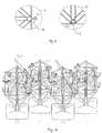
Fig. 1 illustrates the power plant according to the invention located in the water;Fig. 2 is an illustration of the power plant viewed from above;Fig. 3 is an illustration of the power plant viewed from the side;Fig. 4 illustrates the floating unit and components thereof;Fig. 5 is a cross section of connecting means for interconnecting several floating units, taken as a section fromfig. 4 ;Fig. 6 illustrates the relative vertical motion of several interconnected floating units in perspective, andFig. 7 illustrates an alternative embodiment of the invention, where a hydraulic cylinder is placed between two floating elements, and where the relative motion of the floating elements drives the hydraulic cylinder. Infig. 7 the float is integrated in and attached to the framework.- We now refer to
fig. 1 , where apower plant 10 according to the invention is placed in the water. A submarine cable 11 conveys the produced electric energy to land, wherepower lines 14 transport the energy on to consumers. - The power plant in the preferred embodiment consists of an arrangement 20 of floating units 22 (
fig. 2 ). Here the arrangement 20 consists of an array of ten times sevenfloating units 22. In each corner the arrangement 20 is mounted by means of one ormore wires 24 in amooring buoy 26, which anchors the arrangement 20 to the seabed. - A
row 27 of floating units comprises generatingunits 28, this row being illustrated at the top offig. 2 and marked by black areas. The generatingunits 28 will be described in detail later. Fig. 3 illustrates how themooring buoys 26 are anchored to the seabed. It should be noted that thewires 24 are equipped with tension accumulators (not shown) for absorbing tension forces. At the same time thewires 24 are adapted in length so that tidal variations do not influence the arrangement.- A
floating unit 22 is illustrated in detail infig. 4 . Thefloating unit 22 comprises afloat 40 attached by means of an articulatedjoint 42 to a cylindrical rod orstabiliser unit 44. To thestabiliser unit 44, above thefloat 40, is attached aframework 46, which absorbs forces in the horizontal and vertical direction for eachfloating unit 22. Thefloat 40 is made of an outer layer of glass fibre or the like, and provides buoyancy to thefloating unit 22. Thefloat 40 is substantially rounded in shape to enable it to move flexibly over the waves, and the articulatedjoint 42 also assists in this since thefloat 40 can pivot both about the longitudinal axis of the articulatedjoint 42 and about the axis perpendicular thereto, at the attachment of the articulatedjoint 42 to thestabiliser unit 44. - The
stabiliser unit 44 is elongated, extending at a depth beneath the surface. Thestabiliser unit 44 preferably consists of a steel pipe filled with concrete or the like, and its purpose is to stabilise thefloating unit 22 in the water so that it maintains a stable vertical position, while at the same time thestabiliser unit 44 will be able to have a damping effect on the dynamic moment forces that may influence thefloating unit 22 due to wave motion. - The
floating units 22 are interconnected by attachment means 48 in theframework 46. The attachment means 48 are illustrated in detail in sections A and B infig. 5 , taken fromfig. 4 . The attachment means 48 are mounted at each corner of theframework 46, and comprise a substantially protruding element 50 (section A) adapted to be able to be received in a substantially hollow element 52 (section B). In the embodiment, therefore, each floating element can be attached to four other floating elements. - It should be noted that the attachment means 48 in
fig. 5 are illustrated from above, and that infig. 4 it can be seen that the attachment means 48 have a longitudinal extension. By this means the protruding element 50 can be moved up and down in the vertical direction relative to the hollow element 52. At the same time it can be seen that the attachment means 48 prevent relative horizontal motion of the floatingunits 22. - This is also illustrated in more detail in
fig. 6 , where four floatingunits 22 are shown displaced relative to one another in the vertical direction. Also depicted here are parts of ahydraulic system 60. Thehydraulic system 60 comprises a number of pump units, which can be seen as a number of rectangular boxes infig. 6 . These pump units are driven by a rotating cogwheel that runs along a toothed rack along the corner of theframework 46 in the adjacent floating unit. The pump unit will be driven when there is relative vertical motion of the floating units, and hydraulic fluid will be pumped to the above-mentionedgenerating units 28. - In an alternative embodiment (
fig. 7 ) the energy is produced by hydraulic cylinders 80 driving the fluid and thereby driving the units. - The generating
units 28 utilise the hydraulic pressure to produce electric energy, which is then transferred via thesubmarine cables 12 to land. The hydraulic fluid at low pressure is then returned to the pump units. The hydraulic system may also include accumulator units for balancing pressure variations. Furthermore, transmission channels in the hydraulic system are preferably provided inside hollow tubes composed of theframework 46, whereby the transmission channels can be shielded from external stresses. - A number of alternative embodiments of the invention may be envisaged. In one alternative embodiment (illustrated in
fig. 7 ) thefloat 40 is integrated in a lower part of the framework. Moreover, there are a number of alternative ways of joining the floating units together, where, for example, the attachment means may comprise rails with track wheels, etc.
Claims (8)
- A wave power generating plant, comprising an arrangement (20) of interconnected floating units (22), where the arrangement (20) is anchored to the seabed via mooring buoys (26), and where each floating unit comprises a floating pontoon (40) connected to a stabiliser unit (44) and where each floating unit (22) is further connected to at least one adjacent floating unit (22) by connecting means (48),
where the connecting means (48) permit a free vertical motion of the floating units (22) relative to one another; where the relative vertical motion of the floating units (22) due to wave influence is transferred via an energy transmission device which in turn drives a power-producing unit;
the stabiliser unit (44) is attached to a framework (46) above the pontoon (40);
where the connecting means (48) keep the interconnected floating units (22) in a constant relative relationship in the horizontal plane;
where the framework (46) is absorbing forces in the horizontal and vertical direction for each floating unit (22); andcharacterized in that
the connecting means (48) comprise a substantially protruding element (50) adapted to be able to be received in a substantially hollow element (52) of the at least one adjacent floating unit (22). - A wave power generating plant according to patent claim 1,
characterised in that the energy transmission device comprises a hydraulic system (60) comprising a number of pump units for generating pressure in a hydraulic fluid in the hydraulic system, and at least one generating unit (28) for utilising the pressure generated in the hydraulic fluid for production of electric energy. - A wave power generating plant according to patent claim 2,
characterised in that the pump units are driven by the relative vertical motion of the floating units (22). - A wave power generating plant according to patent claim 3,
characterised in that the floating units comprise a horizontal toothed rack which, on relative motion of the floating unit relative to adjacent floating units, rotates a cogwheel in the adjacent floating unit, whereupon the cogwheel drives one of the pump units. - A wave power generating plant according to one or more of the preceding claims, where the floating units pump hydraulic fluid to the unit in series or in parallel.
- A wave power generating plant according to one or more of the preceding claims, where the pontoon (40) is attached by means of an articulated joint (42) to the stabiliser unit (44).
- A wave power generating plant according to claim 6, where the pontoon (40) is pivotable both about the longitudinal axis of the articulated joint (42) and about the axis perpendicular thereto, at the attachment of the articulated joint (42) to the stabiliser unit (44).
- A wave power generating plant according to one or more of the preceding claims, where the connecting means (48) are mounted at each corner of the framework (46).
Applications Claiming Priority (2)
| Application Number | Priority Date | Filing Date | Title |
|---|---|---|---|
| NO20043825ANO320518B1 (en) | 2004-09-13 | 2004-09-13 | Bolgekraftverk |
| PCT/NO2005/000326WO2006031121A1 (en) | 2004-09-13 | 2005-09-08 | Wave power generating plant |
Publications (3)
| Publication Number | Publication Date |
|---|---|
| EP1805413A1 EP1805413A1 (en) | 2007-07-11 |
| EP1805413A4 EP1805413A4 (en) | 2012-08-22 |
| EP1805413B1true EP1805413B1 (en) | 2014-08-20 |
Family
ID=35057602
Family Applications (1)
| Application Number | Title | Priority Date | Filing Date |
|---|---|---|---|
| EP05786626.1ACeasedEP1805413B1 (en) | 2004-09-13 | 2005-09-08 | Wave power generating plant |
Country Status (4)
| Country | Link |
|---|---|
| US (1) | US7629703B2 (en) |
| EP (1) | EP1805413B1 (en) |
| NO (1) | NO320518B1 (en) |
| WO (1) | WO2006031121A1 (en) |
Families Citing this family (20)
| Publication number | Priority date | Publication date | Assignee | Title |
|---|---|---|---|---|
| CA2621244C (en)* | 2005-09-02 | 2012-10-30 | John Christopher Burtch | Apparatus for production of hydrogen gas using wind and wave action |
| US7755211B2 (en)* | 2006-06-17 | 2010-07-13 | Montgomery James Scott | Rigid structural array |
| NO326269B1 (en)* | 2007-01-30 | 2008-10-27 | Ernst Johnny Svelund | Facility for utilization of ocean energy. |
| IL190300A0 (en)* | 2008-03-19 | 2009-09-22 | S D E Ltd | System and method for water desalination and other uses |
| ES2365461B1 (en)* | 2008-03-24 | 2013-02-15 | Manuel MUÑOZ SÁIZ | ENTREPRENEUR SYSTEM AND ATENUADOR OF THE ENERGY OF THE WAVES OF THE SEA THROUGH IRONS, PLATES, CANVAS AND SIMILAR. |
| US8183708B2 (en)* | 2008-07-25 | 2012-05-22 | Carl Stanley Reiff | Open ocean wave energy converter with isolated stabilization floats |
| DE102008048730B4 (en)* | 2008-09-24 | 2010-10-07 | Philipp Sinn | Wave or pulse power plant |
| WO2010042358A2 (en)* | 2008-10-09 | 2010-04-15 | E. I. Du Pont De Nemours And Company | Wave energy conversion device |
| CN102414443A (en)* | 2009-03-09 | 2012-04-11 | 自然动力概念公司 | System and method for generating electricity using grid of wind and water energy capture devices |
| BR112012014103B1 (en)* | 2009-12-04 | 2017-02-14 | Henry Terry | ocean powered power plant |
| NO20100589A1 (en)* | 2009-12-23 | 2011-06-24 | Nader Hassavari | Device for utilization of bulge energy |
| US8727872B2 (en) | 2011-02-23 | 2014-05-20 | Igt | Gaming system, gaming device and method for normalizing different features of an on-demand bonus game |
| FR2982648A1 (en)* | 2011-11-16 | 2013-05-17 | Claude Windeck | PONTON INERTIAL FLOATING HUMMER, HAS A NUMBER OF SMALL FLOATER / PUMP MODULES, THAT TRANSFORM THE ENERGY OF THE HELL INTO ELECTRICAL ENERGY |
| DE102013201716B4 (en)* | 2013-02-01 | 2015-06-03 | Sinn Power Gmbh | LINEAR GENERATOR AND LINEAR DRIVE |
| US10221829B2 (en) | 2014-02-27 | 2019-03-05 | Maciej STAMIRSKI | Modular, scalable and mobile wave energy conversion arrangement |
| US9347425B2 (en)* | 2014-06-03 | 2016-05-24 | Christopher Wright | Offshore floating barge to support sustainable power generation |
| DE102015121371B4 (en)* | 2015-12-08 | 2018-11-15 | Aerodyn Consulting Singapore Pte Ltd | Offshore wind farm |
| TWI680229B (en) | 2016-11-25 | 2019-12-21 | 財團法人工業技術研究院 | Separable buoy |
| US9957018B1 (en)* | 2017-02-07 | 2018-05-01 | Cvetan Angeliev | System for wave amplifying, wave energy harnessing, and energy storage |
| GB2559996A (en)* | 2017-02-23 | 2018-08-29 | Sustainable Marine Energy Ltd | Flowing water power generating device |
Family Cites Families (74)
| Publication number | Priority date | Publication date | Assignee | Title |
|---|---|---|---|---|
| US632826A (en)* | 1898-11-04 | 1899-09-12 | Merrill B Rice | Wave-motor. |
| US1244309A (en)* | 1916-09-14 | 1917-10-23 | William Clay Fox | Wave-motor. |
| US1497205A (en)* | 1922-06-14 | 1924-06-10 | Charles F Boosinger | Wave motor |
| DE487512C (en) | 1927-08-27 | 1929-12-10 | Soma Prisner | Wave power plant |
| US1766457A (en)* | 1928-04-23 | 1930-06-24 | Charles H Ruth | Wave and tide motor |
| US3204110A (en)* | 1961-07-07 | 1965-08-31 | Masuda Yoshio | Ocean wave electric generator |
| US3758788A (en)* | 1971-06-14 | 1973-09-11 | D Richeson | Conversion system for providing useful energy from water surface motion |
| US3777494A (en)* | 1972-01-10 | 1973-12-11 | A Soderlund | Wave energy motors |
| FR2225042A5 (en) | 1973-04-04 | 1974-10-31 | Zanetti Streccia Giuseppe | |
| US4111610A (en)* | 1974-06-03 | 1978-09-05 | Brown Henry C | Wave-powered, pivoted float pumping system with increasing opposition to extreme movement of lever arm |
| US4013382A (en)* | 1975-10-14 | 1977-03-22 | Diggs Richard E | Wave power apparatus supported and operated by floats in water |
| US4125346A (en)* | 1975-10-15 | 1978-11-14 | Pickle William H | Random wave hydraulic engine |
| US4077213A (en)* | 1976-02-13 | 1978-03-07 | Williams, Inc. | Wave driven generator |
| USRE31111E (en)* | 1976-02-13 | 1982-12-28 | Williams, Inc. | Wave driven generator |
| GB1571283A (en)* | 1976-03-31 | 1980-07-09 | Wavepower Ltd | Apparatus for extracting energy from movement of water |
| US4092828A (en)* | 1976-05-10 | 1978-06-06 | Garza Roberto M | Hydroelectric plant |
| US4091618A (en)* | 1976-06-14 | 1978-05-30 | Jackson Arlyn H | Ocean motion power generating system |
| US4076463A (en)* | 1976-10-26 | 1978-02-28 | Mordechai Welczer | Wave motor |
| US4105368A (en)* | 1976-11-15 | 1978-08-08 | Waters Fred L | Floating wave powered pump |
| US4206601A (en)* | 1978-06-26 | 1980-06-10 | Benasutti Asst., Ltd. | Compressed air producing, tidal and wave-power collection apparatus for installation in large bodies of water |
| US4241579A (en)* | 1978-09-14 | 1980-12-30 | Hydrodynamic Energy Systems Corporation | Apparatus for producing electrical energy from multidirectional water wave action |
| US4560884A (en)* | 1979-07-16 | 1985-12-24 | Whittecar William C | Wave power energizer |
| WO1981000284A1 (en)* | 1979-07-24 | 1981-02-05 | A Paolucci | Wave driven generator |
| US4421461A (en)* | 1979-09-17 | 1983-12-20 | University Of Delaware | Wave-powered desalination of seawater |
| US4326840A (en)* | 1980-03-10 | 1982-04-27 | University Of Delaware | Wave driven pump |
| US4392349A (en)* | 1980-07-21 | 1983-07-12 | Hagen Glenn E | Spaced apart wave generator float array |
| US4408454A (en)* | 1980-07-21 | 1983-10-11 | Sea Energy Corporation | Fluid coupled wave generator array with subsea structure |
| GB2084259B (en)* | 1980-07-22 | 1984-06-13 | Kawasaki Heavy Ind Ltd | Wave activated power generation system |
| US4512886A (en)* | 1981-05-26 | 1985-04-23 | University Of Delaware | Wave-powered desalination of water |
| US4594853A (en)* | 1984-03-12 | 1986-06-17 | Wave Power Industries | Wave powered generator |
| US4698969A (en)* | 1984-03-12 | 1987-10-13 | Wave Power Industries, Ltd. | Wave power converter |
| US4622473A (en) | 1984-07-16 | 1986-11-11 | Adolph Curry | Wave-action power generator platform |
| US4754157A (en)* | 1985-10-01 | 1988-06-28 | Windle Tom J | Float type wave energy extraction apparatus and method |
| US4684815A (en)* | 1986-01-10 | 1987-08-04 | Gary Gargos | Power plant driven by waves |
| US4742241A (en) | 1986-04-01 | 1988-05-03 | Melvin Kenneth P | Wave energy engine |
| DK166969B1 (en)* | 1990-10-03 | 1993-08-09 | Danish Wave Power | HUMAN POWER PLANT |
| US5186822A (en)* | 1991-02-25 | 1993-02-16 | Ocean Resources Engineering, Inc. | Wave powered desalination apparatus with turbine-driven pressurization |
| WO1994015096A1 (en)* | 1991-04-02 | 1994-07-07 | Sieber Joseph D | Wave powered energy generator |
| US5247899A (en)* | 1992-06-04 | 1993-09-28 | Boesser Sara L | Ramp and platform harbor access system |
| US5411377A (en)* | 1993-03-17 | 1995-05-02 | Houser; Michael P. | Mass displacement wave energy conversion system |
| DE19515138C2 (en) | 1995-04-25 | 1998-07-30 | Marcus Dr Fedder | Wave power station |
| DE19615115A1 (en) | 1996-04-17 | 1997-10-23 | Hagenbaeumer Michael A | Wave-powered power generation plant |
| KR100254657B1 (en)* | 1996-04-18 | 2000-05-01 | 심현진 | Wave power generation method and device |
| SE508307C2 (en)* | 1996-04-29 | 1998-09-21 | Ips Interproject Service Ab | wave energy converters |
| SE508308C2 (en)* | 1996-04-29 | 1998-09-21 | Ips Interproject Service Ab | wave energy converters |
| JP4128241B2 (en)* | 1996-12-03 | 2008-07-30 | 大洋プラント株式会社 | Wave power pump operating with wave energy |
| US5846028A (en)* | 1997-08-01 | 1998-12-08 | Hydralift, Inc. | Controlled pressure multi-cylinder riser tensioner and method |
| DE69817608D1 (en)* | 1997-12-03 | 2003-10-02 | William Dick | SEA wave transducer |
| GB9804770D0 (en)* | 1998-03-07 | 1998-04-29 | Engineering Business Ltd | Apparatus for extracting power from moving water |
| US6291904B1 (en)* | 1998-08-21 | 2001-09-18 | Ocean Power Technologies, Inc. | Wave energy converter utilizing pressure differences |
| GB9820704D0 (en)* | 1998-09-24 | 1998-11-18 | Yemm Richard | Wave energy convertor |
| US6388342B1 (en)* | 1999-07-28 | 2002-05-14 | Richard C. Vetterick, Sr. | Hydro electric plant |
| US6768216B1 (en)* | 2000-05-26 | 2004-07-27 | Ocean Power Technologies, Inc. | Wave energy converters utilizing pressure differences |
| US6647716B2 (en)* | 2000-06-08 | 2003-11-18 | Secil Boyd | Ocean wave power generator (a “modular power-producing network”) |
| IES20000493A2 (en)* | 2000-06-16 | 2002-02-06 | Wavebob Ltd | Wave energy converter |
| US6328539B1 (en)* | 2000-06-30 | 2001-12-11 | Sheng Hu Hung | Hydraulic device powered by wave |
| US7121536B2 (en)* | 2002-01-09 | 2006-10-17 | Pond Doctor, Inc. | Wave generator with oxygen injection for treatment of a body of fluid |
| WO2004007953A1 (en)* | 2002-07-11 | 2004-01-22 | Alvin Kobashikawa | Wave energy conversion device for desalination, etc. |
| US7257946B2 (en)* | 2002-10-10 | 2007-08-21 | Independent Natural Resources, Inc. | Buoyancy pump power system |
| AP2009004875A0 (en)* | 2002-10-10 | 2009-06-30 | Independent Natural Resources | Sea wave energy converter |
| US6953328B2 (en)* | 2002-10-10 | 2005-10-11 | Independent Natural Resources, Inc. | Buoyancy pump device |
| GB0307827D0 (en)* | 2003-04-04 | 2003-05-07 | Ocean Power Delivery Ltd | Wave power apparatus |
| PT1678419E (en)* | 2003-10-14 | 2012-11-29 | Wave Star As | Wave power apparatus |
| US6812588B1 (en)* | 2003-10-21 | 2004-11-02 | Stephen J. Zadig | Wave energy converter |
| NO321085B1 (en)* | 2004-04-02 | 2006-03-13 | Asbjorn Skotte | Bolgekraftverk. |
| US7391127B2 (en)* | 2004-11-09 | 2008-06-24 | Shamil Sami Ayntrazi | Renewable energy wave pump |
| CA2590612A1 (en)* | 2004-12-16 | 2006-06-22 | Independent Natural Resources, Inc. | Buoyancy pump power system |
| GB0501553D0 (en)* | 2005-01-26 | 2005-03-02 | Nordeng Scot Ltd | Method and apparatus for energy generation |
| US20060202483A1 (en)* | 2005-03-14 | 2006-09-14 | Gonzalez Enrique J | Capturing energy from the rise and fall of the tides and waves of the ocean |
| US20070130929A1 (en)* | 2005-12-13 | 2007-06-14 | Ghazi Khan | Wave power generator |
| US7339285B2 (en)* | 2006-01-12 | 2008-03-04 | Negron Crespo Jorge | Hydroelectric wave-energy conversion system |
| US7245041B1 (en)* | 2006-05-05 | 2007-07-17 | Olson Chris F | Ocean wave energy converter |
| US7755211B2 (en)* | 2006-06-17 | 2010-07-13 | Montgomery James Scott | Rigid structural array |
| US7535117B2 (en)* | 2006-06-17 | 2009-05-19 | Montgomery James Scott | Ocean wave power recovery and conversion spar buoy engine |
- 2004
- 2004-09-13NONO20043825Apatent/NO320518B1/ennot_activeIP Right Cessation
- 2005
- 2005-09-08EPEP05786626.1Apatent/EP1805413B1/ennot_activeCeased
- 2005-09-08USUS11/575,133patent/US7629703B2/ennot_activeExpired - Fee Related
- 2005-09-08WOPCT/NO2005/000326patent/WO2006031121A1/enactiveApplication Filing
Also Published As
| Publication number | Publication date |
|---|---|
| US20080036213A1 (en) | 2008-02-14 |
| EP1805413A1 (en) | 2007-07-11 |
| NO20043825A (en) | 2005-12-12 |
| EP1805413A4 (en) | 2012-08-22 |
| NO20043825D0 (en) | 2004-09-13 |
| WO2006031121A1 (en) | 2006-03-23 |
| US7629703B2 (en) | 2009-12-08 |
| NO320518B1 (en) | 2005-12-12 |
Similar Documents
| Publication | Publication Date | Title |
|---|---|---|
| EP1805413B1 (en) | Wave power generating plant | |
| US8912677B2 (en) | Method and apparatus for converting ocean wave energy into electricity | |
| EP2016281B1 (en) | Improved wave energy converter (wec) with heave plates | |
| US9309860B2 (en) | Wave energy conversion device | |
| US10227961B2 (en) | System for conversion of wave energy into electrical energy | |
| US9523346B2 (en) | Modular array type energy converter | |
| CN101611226B (en) | Energy extraction method and apparatus | |
| US20090066085A1 (en) | Energy Transformation Device | |
| CN102149918A (en) | Wave powered generator | |
| CN103221682A (en) | Systems and methods for renewable electricity production using wave energy | |
| CN110015384A (en) | Semi-submersible type offshore wind power and aquaculture fishing ground platform integrated structure | |
| RU2150021C1 (en) | Method and megawatt-capacity power-plant module for recovering energy of reusable sources (options) | |
| CN107476930A (en) | A kind of twin float, damping riser wave energy generating set | |
| KR20150072491A (en) | Oscillating Water Column Type Wave Energy Harvest | |
| KR20110059880A (en) | Marine wave energy converter | |
| US20180202414A1 (en) | Dynamic wave power energy converter | |
| US11441532B2 (en) | Submerged oscillating water column energy harvester | |
| HU201829B (en) | Combined wave power machine | |
| CN117028124B (en) | Single pile foundation wave energy power generation device and cluster power generation system | |
| US20190136823A1 (en) | Modular lattice wave motion energy conversion apparatus | |
| JP2025532221A (en) | Integrated floating wave power generation system for offshore platforms |
Legal Events
| Date | Code | Title | Description |
|---|---|---|---|
| PUAI | Public reference made under article 153(3) epc to a published international application that has entered the european phase | Free format text:ORIGINAL CODE: 0009012 | |
| 17P | Request for examination filed | Effective date:20070413 | |
| AK | Designated contracting states | Kind code of ref document:A1 Designated state(s):AT BE BG CH CY CZ DE DK EE ES FI FR GB GR HU IE IS IT LI LT LU LV MC NL PL PT RO SE SI SK TR | |
| DAX | Request for extension of the european patent (deleted) | ||
| A4 | Supplementary search report drawn up and despatched | Effective date:20120725 | |
| RIC1 | Information provided on ipc code assigned before grant | Ipc:F03B 13/18 20060101ALI20120719BHEP Ipc:F03B 13/20 20060101AFI20120719BHEP | |
| REG | Reference to a national code | Ref country code:DE Ref legal event code:R079 Ref document number:602005044545 Country of ref document:DE Free format text:PREVIOUS MAIN CLASS: F03B0013200000 Ipc:E02B0017000000 | |
| RIC1 | Information provided on ipc code assigned before grant | Ipc:F03B 13/18 20060101ALI20131219BHEP Ipc:F03B 13/20 20060101ALI20131219BHEP Ipc:E02B 17/00 20060101AFI20131219BHEP | |
| GRAP | Despatch of communication of intention to grant a patent | Free format text:ORIGINAL CODE: EPIDOSNIGR1 | |
| INTG | Intention to grant announced | Effective date:20140320 | |
| GRAS | Grant fee paid | Free format text:ORIGINAL CODE: EPIDOSNIGR3 | |
| GRAA | (expected) grant | Free format text:ORIGINAL CODE: 0009210 | |
| AK | Designated contracting states | Kind code of ref document:B1 Designated state(s):AT BE BG CH CY CZ DE DK EE ES FI FR GB GR HU IE IS IT LI LT LU LV MC NL PL PT RO SE SI SK TR | |
| REG | Reference to a national code | Ref country code:GB Ref legal event code:FG4D | |
| REG | Reference to a national code | Ref country code:CH Ref legal event code:EP | |
| REG | Reference to a national code | Ref country code:AT Ref legal event code:REF Ref document number:683551 Country of ref document:AT Kind code of ref document:T Effective date:20140915 | |
| REG | Reference to a national code | Ref country code:IE Ref legal event code:FG4D | |
| REG | Reference to a national code | Ref country code:DE Ref legal event code:R096 Ref document number:602005044545 Country of ref document:DE Effective date:20141002 | |
| REG | Reference to a national code | Ref country code:AT Ref legal event code:MK05 Ref document number:683551 Country of ref document:AT Kind code of ref document:T Effective date:20140820 | |
| REG | Reference to a national code | Ref country code:NL Ref legal event code:VDEP Effective date:20140820 | |
| REG | Reference to a national code | Ref country code:LT Ref legal event code:MG4D | |
| PG25 | Lapsed in a contracting state [announced via postgrant information from national office to epo] | Ref country code:GR Free format text:LAPSE BECAUSE OF FAILURE TO SUBMIT A TRANSLATION OF THE DESCRIPTION OR TO PAY THE FEE WITHIN THE PRESCRIBED TIME-LIMIT Effective date:20141121 Ref country code:BG Free format text:LAPSE BECAUSE OF FAILURE TO SUBMIT A TRANSLATION OF THE DESCRIPTION OR TO PAY THE FEE WITHIN THE PRESCRIBED TIME-LIMIT Effective date:20141120 Ref country code:LT Free format text:LAPSE BECAUSE OF FAILURE TO SUBMIT A TRANSLATION OF THE DESCRIPTION OR TO PAY THE FEE WITHIN THE PRESCRIBED TIME-LIMIT Effective date:20140820 Ref country code:SE Free format text:LAPSE BECAUSE OF FAILURE TO SUBMIT A TRANSLATION OF THE DESCRIPTION OR TO PAY THE FEE WITHIN THE PRESCRIBED TIME-LIMIT Effective date:20140820 Ref country code:FI Free format text:LAPSE BECAUSE OF FAILURE TO SUBMIT A TRANSLATION OF THE DESCRIPTION OR TO PAY THE FEE WITHIN THE PRESCRIBED TIME-LIMIT Effective date:20140820 Ref country code:PT Free format text:LAPSE BECAUSE OF FAILURE TO SUBMIT A TRANSLATION OF THE DESCRIPTION OR TO PAY THE FEE WITHIN THE PRESCRIBED TIME-LIMIT Effective date:20141222 Ref country code:ES Free format text:LAPSE BECAUSE OF FAILURE TO SUBMIT A TRANSLATION OF THE DESCRIPTION OR TO PAY THE FEE WITHIN THE PRESCRIBED TIME-LIMIT Effective date:20140820 | |
| PG25 | Lapsed in a contracting state [announced via postgrant information from national office to epo] | Ref country code:IS Free format text:LAPSE BECAUSE OF FAILURE TO SUBMIT A TRANSLATION OF THE DESCRIPTION OR TO PAY THE FEE WITHIN THE PRESCRIBED TIME-LIMIT Effective date:20141220 Ref country code:AT Free format text:LAPSE BECAUSE OF FAILURE TO SUBMIT A TRANSLATION OF THE DESCRIPTION OR TO PAY THE FEE WITHIN THE PRESCRIBED TIME-LIMIT Effective date:20140820 Ref country code:LV Free format text:LAPSE BECAUSE OF FAILURE TO SUBMIT A TRANSLATION OF THE DESCRIPTION OR TO PAY THE FEE WITHIN THE PRESCRIBED TIME-LIMIT Effective date:20140820 | |
| PG25 | Lapsed in a contracting state [announced via postgrant information from national office to epo] | Ref country code:NL Free format text:LAPSE BECAUSE OF FAILURE TO SUBMIT A TRANSLATION OF THE DESCRIPTION OR TO PAY THE FEE WITHIN THE PRESCRIBED TIME-LIMIT Effective date:20140820 | |
| PG25 | Lapsed in a contracting state [announced via postgrant information from national office to epo] | Ref country code:RO Free format text:LAPSE BECAUSE OF FAILURE TO SUBMIT A TRANSLATION OF THE DESCRIPTION OR TO PAY THE FEE WITHIN THE PRESCRIBED TIME-LIMIT Effective date:20140820 Ref country code:CZ Free format text:LAPSE BECAUSE OF FAILURE TO SUBMIT A TRANSLATION OF THE DESCRIPTION OR TO PAY THE FEE WITHIN THE PRESCRIBED TIME-LIMIT Effective date:20140820 Ref country code:SK Free format text:LAPSE BECAUSE OF FAILURE TO SUBMIT A TRANSLATION OF THE DESCRIPTION OR TO PAY THE FEE WITHIN THE PRESCRIBED TIME-LIMIT Effective date:20140820 Ref country code:IT Free format text:LAPSE BECAUSE OF FAILURE TO SUBMIT A TRANSLATION OF THE DESCRIPTION OR TO PAY THE FEE WITHIN THE PRESCRIBED TIME-LIMIT Effective date:20140820 Ref country code:EE Free format text:LAPSE BECAUSE OF FAILURE TO SUBMIT A TRANSLATION OF THE DESCRIPTION OR TO PAY THE FEE WITHIN THE PRESCRIBED TIME-LIMIT Effective date:20140820 Ref country code:DK Free format text:LAPSE BECAUSE OF FAILURE TO SUBMIT A TRANSLATION OF THE DESCRIPTION OR TO PAY THE FEE WITHIN THE PRESCRIBED TIME-LIMIT Effective date:20140820 | |
| REG | Reference to a national code | Ref country code:CH Ref legal event code:PL | |
| REG | Reference to a national code | Ref country code:DE Ref legal event code:R097 Ref document number:602005044545 Country of ref document:DE | |
| PG25 | Lapsed in a contracting state [announced via postgrant information from national office to epo] | Ref country code:MC Free format text:LAPSE BECAUSE OF FAILURE TO SUBMIT A TRANSLATION OF THE DESCRIPTION OR TO PAY THE FEE WITHIN THE PRESCRIBED TIME-LIMIT Effective date:20140820 Ref country code:PL Free format text:LAPSE BECAUSE OF FAILURE TO SUBMIT A TRANSLATION OF THE DESCRIPTION OR TO PAY THE FEE WITHIN THE PRESCRIBED TIME-LIMIT Effective date:20140820 | |
| PLBE | No opposition filed within time limit | Free format text:ORIGINAL CODE: 0009261 | |
| STAA | Information on the status of an ep patent application or granted ep patent | Free format text:STATUS: NO OPPOSITION FILED WITHIN TIME LIMIT | |
| PG25 | Lapsed in a contracting state [announced via postgrant information from national office to epo] | Ref country code:BE Free format text:LAPSE BECAUSE OF NON-PAYMENT OF DUE FEES Effective date:20140930 | |
| 26N | No opposition filed | Effective date:20150521 | |
| PG25 | Lapsed in a contracting state [announced via postgrant information from national office to epo] | Ref country code:CH Free format text:LAPSE BECAUSE OF NON-PAYMENT OF DUE FEES Effective date:20140930 Ref country code:LI Free format text:LAPSE BECAUSE OF NON-PAYMENT OF DUE FEES Effective date:20140930 | |
| PG25 | Lapsed in a contracting state [announced via postgrant information from national office to epo] | Ref country code:SI Free format text:LAPSE BECAUSE OF FAILURE TO SUBMIT A TRANSLATION OF THE DESCRIPTION OR TO PAY THE FEE WITHIN THE PRESCRIBED TIME-LIMIT Effective date:20140820 | |
| PG25 | Lapsed in a contracting state [announced via postgrant information from national office to epo] | Ref country code:CY Free format text:LAPSE BECAUSE OF FAILURE TO SUBMIT A TRANSLATION OF THE DESCRIPTION OR TO PAY THE FEE WITHIN THE PRESCRIBED TIME-LIMIT Effective date:20140820 | |
| PG25 | Lapsed in a contracting state [announced via postgrant information from national office to epo] | Ref country code:LU Free format text:LAPSE BECAUSE OF NON-PAYMENT OF DUE FEES Effective date:20140908 Ref country code:BE Free format text:LAPSE BECAUSE OF FAILURE TO SUBMIT A TRANSLATION OF THE DESCRIPTION OR TO PAY THE FEE WITHIN THE PRESCRIBED TIME-LIMIT Effective date:20140820 Ref country code:TR Free format text:LAPSE BECAUSE OF FAILURE TO SUBMIT A TRANSLATION OF THE DESCRIPTION OR TO PAY THE FEE WITHIN THE PRESCRIBED TIME-LIMIT Effective date:20140820 Ref country code:HU Free format text:LAPSE BECAUSE OF FAILURE TO SUBMIT A TRANSLATION OF THE DESCRIPTION OR TO PAY THE FEE WITHIN THE PRESCRIBED TIME-LIMIT; INVALID AB INITIO Effective date:20050908 | |
| REG | Reference to a national code | Ref country code:FR Ref legal event code:PLFP Year of fee payment:12 | |
| PGFP | Annual fee paid to national office [announced via postgrant information from national office to epo] | Ref country code:DE Payment date:20160831 Year of fee payment:12 | |
| REG | Reference to a national code | Ref country code:FR Ref legal event code:PLFP Year of fee payment:13 | |
| PGFP | Annual fee paid to national office [announced via postgrant information from national office to epo] | Ref country code:FR Payment date:20170904 Year of fee payment:13 | |
| REG | Reference to a national code | Ref country code:DE Ref legal event code:R119 Ref document number:602005044545 Country of ref document:DE | |
| PG25 | Lapsed in a contracting state [announced via postgrant information from national office to epo] | Ref country code:DE Free format text:LAPSE BECAUSE OF NON-PAYMENT OF DUE FEES Effective date:20180404 | |
| PGFP | Annual fee paid to national office [announced via postgrant information from national office to epo] | Ref country code:IE Payment date:20180711 Year of fee payment:14 | |
| PGFP | Annual fee paid to national office [announced via postgrant information from national office to epo] | Ref country code:GB Payment date:20180711 Year of fee payment:14 | |
| PG25 | Lapsed in a contracting state [announced via postgrant information from national office to epo] | Ref country code:FR Free format text:LAPSE BECAUSE OF NON-PAYMENT OF DUE FEES Effective date:20180930 | |
| PG25 | Lapsed in a contracting state [announced via postgrant information from national office to epo] | Ref country code:IE Free format text:LAPSE BECAUSE OF NON-PAYMENT OF DUE FEES Effective date:20190908 | |
| GBPC | Gb: european patent ceased through non-payment of renewal fee | Effective date:20190908 | |
| PG25 | Lapsed in a contracting state [announced via postgrant information from national office to epo] | Ref country code:GB Free format text:LAPSE BECAUSE OF NON-PAYMENT OF DUE FEES Effective date:20190908 |