EP1800615B1 - Bone plate - Google Patents
Bone plateDownload PDFInfo
- Publication number
- EP1800615B1 EP1800615B1EP05028290AEP05028290AEP1800615B1EP 1800615 B1EP1800615 B1EP 1800615B1EP 05028290 AEP05028290 AEP 05028290AEP 05028290 AEP05028290 AEP 05028290AEP 1800615 B1EP1800615 B1EP 1800615B1
- Authority
- EP
- European Patent Office
- Prior art keywords
- bone
- bone plate
- thread
- screw
- elongated hole
- Prior art date
- Legal status (The legal status is an assumption and is not a legal conclusion. Google has not performed a legal analysis and makes no representation as to the accuracy of the status listed.)
- Not-in-force
Links
- 210000000988bone and boneAnatomy0.000titleclaimsabstractdescription135
- 230000007704transitionEffects0.000claimsdescription4
- 238000004873anchoringMethods0.000claims1
- 230000006835compressionEffects0.000description7
- 238000007906compressionMethods0.000description7
- 230000000694effectsEffects0.000description6
- 230000003993interactionEffects0.000description5
- 230000000295complement effectEffects0.000description4
- 230000001054cortical effectEffects0.000description2
- 238000011161developmentMethods0.000description2
- 230000018109developmental processEffects0.000description2
- 230000013011matingEffects0.000description2
- 230000004888barrier functionEffects0.000description1
- 230000001419dependent effectEffects0.000description1
- 238000006073displacement reactionMethods0.000description1
- 238000005553drillingMethods0.000description1
- 230000009977dual effectEffects0.000description1
- 238000003780insertionMethods0.000description1
- 230000037431insertionEffects0.000description1
- 238000003754machiningMethods0.000description1
- 238000000034methodMethods0.000description1
- 238000003801millingMethods0.000description1
- 230000002093peripheral effectEffects0.000description1
- 230000008569processEffects0.000description1
- 230000000284resting effectEffects0.000description1
- 230000001960triggered effectEffects0.000description1
Images


Classifications
- A—HUMAN NECESSITIES
- A61—MEDICAL OR VETERINARY SCIENCE; HYGIENE
- A61B—DIAGNOSIS; SURGERY; IDENTIFICATION
- A61B17/00—Surgical instruments, devices or methods
- A61B17/56—Surgical instruments or methods for treatment of bones or joints; Devices specially adapted therefor
- A61B17/58—Surgical instruments or methods for treatment of bones or joints; Devices specially adapted therefor for osteosynthesis, e.g. bone plates, screws or setting implements
- A61B17/68—Internal fixation devices, including fasteners and spinal fixators, even if a part thereof projects from the skin
- A61B17/80—Cortical plates, i.e. bone plates; Instruments for holding or positioning cortical plates, or for compressing bones attached to cortical plates
- A61B17/8052—Cortical plates, i.e. bone plates; Instruments for holding or positioning cortical plates, or for compressing bones attached to cortical plates immobilised relative to screws by interlocking form of the heads and plate holes, e.g. conical or threaded
- A61B17/8057—Cortical plates, i.e. bone plates; Instruments for holding or positioning cortical plates, or for compressing bones attached to cortical plates immobilised relative to screws by interlocking form of the heads and plate holes, e.g. conical or threaded the interlocking form comprising a thread
- A—HUMAN NECESSITIES
- A61—MEDICAL OR VETERINARY SCIENCE; HYGIENE
- A61B—DIAGNOSIS; SURGERY; IDENTIFICATION
- A61B17/00—Surgical instruments, devices or methods
- A61B17/16—Instruments for performing osteoclasis; Drills or chisels for bones; Trepans
- A61B17/17—Guides or aligning means for drills, mills, pins or wires
- A61B17/1728—Guides or aligning means for drills, mills, pins or wires for holes for bone plates or plate screws
- A—HUMAN NECESSITIES
- A61—MEDICAL OR VETERINARY SCIENCE; HYGIENE
- A61B—DIAGNOSIS; SURGERY; IDENTIFICATION
- A61B17/00—Surgical instruments, devices or methods
- A61B17/56—Surgical instruments or methods for treatment of bones or joints; Devices specially adapted therefor
- A61B17/58—Surgical instruments or methods for treatment of bones or joints; Devices specially adapted therefor for osteosynthesis, e.g. bone plates, screws or setting implements
- A61B17/68—Internal fixation devices, including fasteners and spinal fixators, even if a part thereof projects from the skin
- A61B17/80—Cortical plates, i.e. bone plates; Instruments for holding or positioning cortical plates, or for compressing bones attached to cortical plates
- A61B17/8004—Cortical plates, i.e. bone plates; Instruments for holding or positioning cortical plates, or for compressing bones attached to cortical plates with means for distracting or compressing the bone or bones
- A61B17/8014—Cortical plates, i.e. bone plates; Instruments for holding or positioning cortical plates, or for compressing bones attached to cortical plates with means for distracting or compressing the bone or bones the extension or compression force being caused by interaction of the plate hole and the screws
- A—HUMAN NECESSITIES
- A61—MEDICAL OR VETERINARY SCIENCE; HYGIENE
- A61B—DIAGNOSIS; SURGERY; IDENTIFICATION
- A61B17/00—Surgical instruments, devices or methods
- A61B17/56—Surgical instruments or methods for treatment of bones or joints; Devices specially adapted therefor
- A61B17/58—Surgical instruments or methods for treatment of bones or joints; Devices specially adapted therefor for osteosynthesis, e.g. bone plates, screws or setting implements
- A61B17/68—Internal fixation devices, including fasteners and spinal fixators, even if a part thereof projects from the skin
- A61B17/84—Fasteners therefor or fasteners being internal fixation devices
- A61B17/86—Pins or screws or threaded wires; nuts therefor
- A61B17/8605—Heads, i.e. proximal ends projecting from bone
Definitions
- the inventionrelates to a bone plate.
- Bone platesare known, for example from the CH 462375 , of the WO 2000/53111 , of the WO 2001/54601 or the EP 0760632 B1 ,
- the configuration of the holes in this prior artis that they consist of the combination of two intersecting holes of different diameters and combined to a through hole and each side of the through hole with its fixed diameter has its own functionality and also considered separately must become.
- the other side of the through holewhich has no threaded portion, is only for the insertion of a standard cortex screw suitable, which can also be applied with compression and angle variability.
- a bone screwwhich seen at its screw head in the direction of the screw longitudinal axis arranged one above the other has a threaded portion and smooth-walled portions. These smooth-walled sections serve to pivotally receive the screw in corresponding guides.
- both a thread and a smooth-walled holding structureare equally arranged one above the other in a subsection.
- Thread and smooth-walled holding structurecan be held in a particularly effective position fixed in the bone plate with a bone screw formed with corresponding counter-structures. Due to the interaction of the thread in the oblong hole with a correspondingly formed mating thread on the head or neck of the bone screw, the bone screw is pressed firmly into this holding structure with a counter-structure or abutment structure formed corresponding to the holding structure and thus securely fixed.
- the holding structureis arranged first and in the lower region of the bone plate, the thread or vice versa.
- the thread or vice versamay be provided alternately and interrupted by at least one portion having a holding structure a plurality of threaded portions in the bone plate.
- Preferredis an embodiment in which the threaded portion is close to the top of the bone plate and a support structure near the bottom of the bone plate (see claim 4).
- the provided with thread and support structure portion of the elongated holeis inventively limited to a portion of the elongated hole, it is preferably located on a narrow side of the elongated hole (see claim 8).
- the thread in the plane of the surface seenengages a maximum of 180 ° of a circular circumference of a to be engaged with this screw head or a neck of a bone screw.
- This configurationcauses a bone screw along the longitudinal axis of the elongated hole is freely displaced, thus thus both for applying a force applied to the fracture site contact force can be used as well as the angle-fixed fixing of the plate.
- a part-spherical surfaceis preferred as the support structure.
- a correspondingly spherical or partially spherical trained surface of the head or Hal ses bone screwcan be set.
- puncture in the transition region between the thread and the support structurefacilitates transfer of the screw head or neck, more precisely of the threaded portion thereof, in the threaded portion of the elongated hole, in particular during a displacement the bone screw along the long hole.
- the slothas a circumferential guide structure at the top of the bone plate.
- This guide structuremay be, for example, a peripheral edge with a part-circular cross-section in which a correspondingly spherical or partially spherical counter-structure can slide on the head or neck of a bone screw.
- the guide structuredefines a management plane. This guide plane is one such plane within which an imaginary point slides on the screw head as the screw is displaced along the guide structure.
- this guide plane of a longitudinal axis of the threadthis is in the context of the invention, the axis about which a screwed into the thread counter thread during a screwing, cut by a 90 ° angle shifting.
- This kind of Tilting between the thread and the guide planeensures that even with a lying in the plane of the surface wrap of a maximum of 180 °, the thread respectively the support structure the screw head or -hals a secure grip, since the tilting to an effective further wrap around at least in a partial area of the thread leads. This effect is achieved by a "clamping" or “wedging effect” triggered by the tilting.
- the guide planeis inclined at an angle between 0 ° and 90 ° with respect to the plane of the plate (claim 7).
- the thread or the support structureare arranged in a portion of the elongated hole in which the guide plane at the lowest, i. farthest from the top of the bone plate lies (see claim 8).
- elongated holeis understood not merely to be a hole image produced by displacing a circle along a straight axis, but basically to any opening shape which is longer in a first extension direction than in a second extension direction and which is continuous, ie. without “barriers” protruding into the hole.
- a slot in the context of the invention“triangular tapering” may be formed and oval.
- a systemcomprising a bone plate as described above and a bone screw is specified with the invention.
- the bone screw of this system according to the inventionhas a screw head or screw neck, arranged on which one above the other and arranged to match the corresponding counter-structures in the bone plate a threaded structure and a complementary to the holding structure of the elongated hole formed investment structure.
- the bone platecan be fixed and clamped at the same time angle-stable with such a specially trained bone screw.
- the bone plate according to the inventioncan also be fixed with standard bone screws or bone screws that are similar to standard bone screws, which in particular have neither a thread nor an abutment structure on their screw head or neck.
- a portion of a system belonging, inventively designed bone screw(for example, the thread) is formed in its outer contour corresponding to the cross section of the guide structure, so that a bone screw according to the invention can be performed in the guide structure.
- a bone screw otherwise designed for fixing the bone plate in an angle-stable mannercan also be used for "clamping" the bone plate.
- the bone plate according to the inventionoffers - also together with the system associated bone screw - a wide variety of applications, which makes them suitable for fixing a variety of fractures.
- all openings in the bone plateare formed as slots with the properties of the invention.
- an embodiment of a bone plate according to the inventionis shown schematically and generally designated 1.
- the exemplary embodiment shownis by no means to scale, but merely serves to explain in principle.
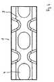
- the bone plate 1 according to the inventionhas an upper side and a lower side 3, which serves for resting on the bone to be fixed. Between top and bottom continuous openings in the form of slots 4 are placed in the bone plate.
- the slots 4are continuous, i. formed without any inward-reaching projections or similar obstacles.
- the bone plate 1 according to the inventionhas in this embodiment a total of eight slots 4, but without being limited to this number.
- the elongated holes 4are formed tapering in the preferred embodiment to one of the longitudinal sides. However, as shown, for example, in an alternative embodiment according to FIG. 4, they can also run straight and correspond to the shape that arises by displacing a circle along a predetermined path. Of course, all other conceivable forms of oblong holes are possible as long as they are continuous, i. are designed in their inner obstacle free.
- each elongated holeOn a front side of each elongated hole a thread 5 and a support structure 6 are formed.
- the thread 5 and the support structure 6are arranged one above the other in a direction transverse to the plane of the plate, in this embodiment, the thread 5 above (the top 2 of the bone plate 1 facing) and the support structure 6 below (the Bottom 3 of the bone plate 1 facing) are arranged.
- a recess 7is introduced in the transition region between thread 5 and holding structure 6, a recess 7 is introduced.
- the support structure 6is formed by a smooth-walled, part-spherical wall portion of the elongated hole.
- the thread 5 and holding structures 6 of the elongated holes 4are arranged on the narrow sides of the latter in the illustrated embodiment, namely on the narrow tapered sides, which are each aligned in the direction of the center of the plate ,
- the longer longitudinal axes of the oblong holes 4extend along a plate longitudinal axis.
- the slot 4contains on its upper side 2 of the bone plate 1 facing opening a circumferential guide structure 8.
- Thisis formed by an edge with teilnikförmigem cross section, which is introduced into the slot 4, for example by a machining step (eg milling).
- a "bathtub-like" profile of this edge, that is to say the guide structure 8,is shown for illustrative purposes.
- the guide structure 8is inclined at an angle ⁇ to the course of the plate plane E P determined by the course of the upper side 2 of the bone plate 1.
- the guide plane E Lis also inclined relative to a thread longitudinal axis A G , namely by an angle ⁇ .
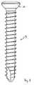
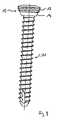
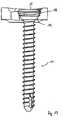
- FIGS. 8 and 9show a standard bone screw 9 (FIG. 8) with a screw head 10, which is smooth and spherically shaped on the underside, or a bone screw 11 (FIG. 9) designed especially for interaction with the bone plate 1 according to the invention Screw head 12 shown.
- the screw head 12includes at an upper Section a spherically shaped in this embodiment thread 13 and seen in the direction of the longitudinal axis of the screw below a portion with a contact structure 14.
- This investment structure 14is smooth-walled formed with spherical or teilsphärischen course, and it is complementary to the shape of the support structure 6 of the bone plate 1.
- FIGS. 10 to 13show the interaction between a bone screw 9 of the conventional type or a bone screw 11 of the type adapted according to the invention and the bone plate 1 according to the invention.
- the function of the bone plate 1 according to the invention and its elementswill now be explained with reference to these figures.
- FIGS. 10 and 11a conventional bone screw 9 inserted in the oblong hole 4 of the bone plate 1 is shown in two different positions.
- This bone screwrests with the spherically smooth underside of the screw head 10 on the complementarily shaped guide structure 8 of the elongated hole 4 and can thus be moved along the longitudinal axis of the elongated hole 4 following the guide plane E L. Due to the misalignment of the guide plane E L , when the bone screw 9 is screwed in, a compression effect is achieved by pressing the bone plate 1 in one direction or pulling a bone to be fixed in the other direction. As can be seen in FIG.
- the serrations of the thread 5 pointing into the interior of the oblong hole 4are shaped such that they likewise form a guide surface formed complementary to the conically shaped underside of the screw head 10. This thus forms part of the guide structure 8.
- the conventional bone screw 9 relative to the vertical(according to the direction the thread axis A G ) are tilted. This gives a variety of ways to fix the bone screw 9 in the bone. This tilting is possible not only in one direction along the longitudinal axis of the elongated hole here, but also in directions transverse thereto, so that ultimately results in a range of substantially 360 °, in which the screw relative to the threaded axis A G can be tilted.
- Such a conventional bone screw 9can be used with the bone plate 1 according to the invention to achieve a compression effect.
- this bone screwis not suitable for achieving an angularly stable fixation in bone plate 1 and bone.
- the bone screw 11 adapted to the bone plate according to the inventioncan be used, as described below with reference to FIGS. 12 and 13.
- the threaded portion 13 of the screw head 12has an outer contour (an envelope of the thread), which is also spherical and complementary to the contour of the guide structure 8.
- the bone screw 11can be performed in the same way in the guide structure 8, as the bone screw 9.
- the peculiarity of the bone screw 11is, however, that it can be fixed in a stable position in the slot 4 of the bone plate 1. This situation is shown in FIG. In this position, the thread 13 of the screw head 12 engages in the thread 5 in the slot 4, and the contact structure 14 is positively against the support structure 6 at.
- the investment structure 14is pressed firmly against the support structure 6, wherein noted is that the support structure 6 and the thread 5 are also formed coaxially, as the thread 13 and the abutment structure 14 on the screw head 12.
- the transition of the screw head 12, more precisely the thread 13 on the screw head 12 in the thread 5 in the slot 4is facilitated by the groove 7.
- the beginning of the thread of the thread 13can be safely transferred into the thread 5, so that he ultimately engages in the thread 5 without tilting.
- the thread 5surrounds the screw head 12 and the thread 13 at the same in a plane of the surface 2 of the bone plate 1 as seen by a maximum of 180 °.
- the screw 11is maintained in its position due to a clamping effect achieved by tilting the guide plane E L relative to the longitudinal thread axis A G.
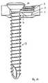
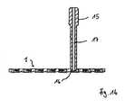
- FIGS. 14 and 15show how, for the operation for installing the bone plate, drill sleeves are connected to the bone plate.
- the situation illustrated in FIG. 14shows a simple drill sleeve 15 which has spherical thread 16 and bearing structure (corresponding to the structures on the screw head 12 of the bone screw 11) formed in its lower end into the thread 5 and the holding structure 6 on the inner side of the elongated hole 4 is screwed in.
- the drill sleeve 15is in its interior a drill channel 17 which extends through the mating fit of the thread 16 and the investment structure of the drill sleeve 15 along the axis A G.
- the drill sleeve 15serves as an aid to the Bore the bone to be supplied with the bone plate 1 ensure that the borehole perpendicular to the bone plate 1 and so a bone screw 11 can be screwed angle stable so in the bone that her screw head 12 with the thread 13 and the contact structure 14 easily into the thread 5 or the holding structure 15 engages.
- FIG. 15shows a variant in which a further drill sleeve 18 is placed on a drill sleeve 15 such that the drill channel 19 of this drill sleeve 18 lies exactly parallel to the axis A G.
- screw holescan be drilled in the bone, which allow the above-described dual function of a bone screw 11.
- the bone screw 11is thereby screwed in such a vertical angle in the bone, which allows it to slide first for compression along the inclined plane E L of the guide structure 8 and then with the thread 13 and the abutment structure 14 at its screw head 12th securely and unscored into the thread 5 and the support structure 6 on the inside of the elongated hole 4 intervene to be fixed in their angle ultimately.
- This processultimately allows the simultaneous compression and angle fixation with only one screw in a single operation.
- drill sleeves shownare purely exemplary, and there are several ways to achieve the same results with differently designed drill sleeves.
Landscapes
- Health & Medical Sciences (AREA)
- Orthopedic Medicine & Surgery (AREA)
- Surgery (AREA)
- Life Sciences & Earth Sciences (AREA)
- Molecular Biology (AREA)
- Animal Behavior & Ethology (AREA)
- Engineering & Computer Science (AREA)
- Biomedical Technology (AREA)
- Heart & Thoracic Surgery (AREA)
- Medical Informatics (AREA)
- Veterinary Medicine (AREA)
- Nuclear Medicine, Radiotherapy & Molecular Imaging (AREA)
- General Health & Medical Sciences (AREA)
- Public Health (AREA)
- Neurology (AREA)
- Dentistry (AREA)
- Oral & Maxillofacial Surgery (AREA)
- Surgical Instruments (AREA)
- Polishing Bodies And Polishing Tools (AREA)
- Materials For Photolithography (AREA)
Abstract
Description
Translated fromGermanDie Erfindung betrifft eine Knochenplatte.The invention relates to a bone plate.
Knochenplatten sind beispielsweise bekannt aus der
Die Ausgestaltung der Löcher ist bei diesem Stand der Technik so, dass sie aus der Kombination von zwei sich überschneidenden Löchern bestehen mit unterschiedlichen Durchmessern und zu einem Durchgangsloch kombiniert sind und jede Seite des Durchgangslochs mit seinem festen Durchmesser seine eigene Funktionalität aufweist und auch getrennt voneinander betrachtet werden muss.The configuration of the holes in this prior art is that they consist of the combination of two intersecting holes of different diameters and combined to a through hole and each side of the through hole with its fixed diameter has its own functionality and also considered separately must become.
So ist es beispielsweise nicht möglich, auf der gewindeanteiligen Seite des Durchgangsloches eine Standard-Kortikalisschraube einzubringen, sondern nur eine Schraube mit Kopfgewinde.For example, it is not possible to insert a standard cortical screw on the threaded part side of the through-hole, but only one screw with a head thread.
Die andere Seite des Durchgangsloches, die keinen Gewindeanteil aufweist, ist nur für die Einbringung einer Standard-Kortikalisschraube geeignet, die auch mit Kompression und Winkelvariabilität appliziert werden kann.The other side of the through hole, which has no threaded portion, is only for the insertion of a standard cortex screw suitable, which can also be applied with compression and angle variability.
Somit könnte man die Löcher auch völlig voneinander trennen da sie keine funktionellen Schnittpunkte aufweisen.Thus, one could also separate the holes completely from each other because they have no functional intersections.
Dieser Nachteil zieht sich dann auch durch die gesamte Anwendung hin, denn beim Einbringen einer Standard-Kortikalisschraube muss auch darauf geachtet werden, dass man sich auch immer auf der richtigen Seite des Durchgangsloches befindet.This drawback then also runs through the entire application, because when introducing a standard cortical screw must also be taken to ensure that you are always on the right side of the through hole.
Aus der
Ausgehend hiervon ist es die Aufgabe der Erfindung, die Einsatzmöglichkeiten einer Knochenplatte zu verbessern und deren Flexibilität in der Handhabung zu erhöhen.Based on this, it is the object of the invention to improve the possible uses of a bone plate and to increase its flexibility in handling.
Gelöst wird diese Aufgabe durch eine Knochenplatte mit den Merkmalen des Anspruchs 1. Vorteilhafte Weiterbildungen sind in den abhängigen Ansprüchen 2 bis 8 angegeben. In Anspruch 9 schließlich ist ein System aus einer erfindungsgemäßen Knochenplatte und wenigstens einer dazu passenden Knochenschraube angegeben, das insgesamt als ein Fixierungssystem angesehen werden kann.This object is achieved by a bone plate with the features of
Erfindungswesentlich ist für die neuartige Knochenplatte, dass in einer Richtung quer zu der Ebene ihrer Oberseite gesehen gleichermaßen übereinander angeordnet in einem Teilabschnitt sowohl ein Gewinde als auch eine glattwandige Haltestruktur angeordnet sind. Durch das Zusammenwirken von Gewinde und glattwandiger Haltestruktur kann eine mit entsprechenden Gegenstrukturen ausgebildete Knochenschraube besonders effektiv lagefixiert in der Knochenplatte gehalten werden. Durch das Zusammenwirken des Gewindes in dem Langloch mit einem entsprechend ausgebildeten Gegengewinde am Kopf bzw. Hals der Knochenschraube wird die Knochenschraube mit einer korrespondierend zu der Haltestruktur ausgebildeten Gegenstruktur bzw. Anlagestruktur fest in diese Haltestruktur gepresst und so sicher fixiert.It is essential to the invention for the novel bone plate that, viewed in a direction transverse to the plane of its upper side, both a thread and a smooth-walled holding structure are equally arranged one above the other in a subsection. Through the interaction of Thread and smooth-walled holding structure can be held in a particularly effective position fixed in the bone plate with a bone screw formed with corresponding counter-structures. Due to the interaction of the thread in the oblong hole with a correspondingly formed mating thread on the head or neck of the bone screw, the bone screw is pressed firmly into this holding structure with a counter-structure or abutment structure formed corresponding to the holding structure and thus securely fixed.
Dabei ist es grundsätzlich egal, ob von der Oberseite der Platte her gesehen die Haltestruktur zuerst und im unteren Bereich der Knochenplatte das Gewinde angeordnet ist oder umgekehrt. Ebenso gut können wechselnd und jeweils unterbrochen durch wenigstens einen Abschnitt mit einer Haltestruktur mehrere Gewindeabschnitte in der Knochenplatte vorgesehen sein. Bevorzugt wird ein Ausführungsbeispiel, bei dem der Gewindeabschnitt nahe der Oberseite der Knochenplatte liegt und eine Haltestruktur nahe der Unterseite der Knochenplatte (vgl. Anspruch 4).It basically does not matter whether seen from the top of the plate, the holding structure is arranged first and in the lower region of the bone plate, the thread or vice versa. Just as well may be provided alternately and interrupted by at least one portion having a holding structure a plurality of threaded portions in the bone plate. Preferred is an embodiment in which the threaded portion is close to the top of the bone plate and a support structure near the bottom of the bone plate (see claim 4).
Der mit Gewinde und Haltestruktur versehene Abschnitt des Langloches ist erfindungsgemäß auf einen Teilabschnitt des Langloches beschränkt, er liegt vorzugsweise an einer Schmalseite des Langloches (vgl. Anspruch 8).The provided with thread and support structure portion of the elongated hole is inventively limited to a portion of the elongated hole, it is preferably located on a narrow side of the elongated hole (see claim 8).
Insbesondere ist in einer vorteilhaften Weiterbildung vorgesehen, dass das Gewinde in der Ebene der Oberfläche gesehen maximal 180° eines kreisförmigen Umfanges eines mit diesem in Eingriff zu bringenden Schraubenkopfes bzw. eines -halses einer Knochenschraube umgreift. Diese Ausgestaltung bewirkt, dass eine Knochenschraube entlang der Längsachse des Langloches frei verschiebbar ist, somit also sowohl zum Aufbringen einer auf die Frakturstelle hingerichteten Anpresskraft als auch zum winkelfesten Fixieren der Platte verwendet werden kann.In particular, it is provided in an advantageous development that the thread in the plane of the surface seen engages a maximum of 180 ° of a circular circumference of a to be engaged with this screw head or a neck of a bone screw. This configuration causes a bone screw along the longitudinal axis of the elongated hole is freely displaced, thus thus both for applying a force applied to the fracture site contact force can be used as well as the angle-fixed fixing of the plate.
Derzeit wird als Haltestruktur eine teilsphärische Fläche bevorzugt. In dieser kann eine entsprechend sphärisch bzw. teilsphärisch ausgebildete Oberfläche des Kopfes bzw. Hal ses der Knochenschraube festgelegt werden. Prinzipiell ist es auch möglich, andere Formen der Oberflächen der Haltestrukturen einzusetzen, beispielsweise konisch.Currently, a part-spherical surface is preferred as the support structure. In this a correspondingly spherical or partially spherical trained surface of the head or Hal ses bone screw can be set. In principle, it is also possible to use other forms of the surfaces of the support structures, for example conical.
Ein wie gemäß einer vorteilhaften Weiterbildung nach Anspruch 5 vorgesehener Einstich im Übergangsbereich zwischen Gewinde und Haltestruktur erleichtert eine Überführung des Schraubenkopfes bzw. -halses, genauer des mit einem Gewinde versehenen Bereiches desselben, in den mit dem Gewinde versehenen Abschnitt des Langloches, insbesondere bei einem Verschieben der Knochenschraube entlang des Langloches.A as provided according to an advantageous embodiment according to claim 5 puncture in the transition region between the thread and the support structure facilitates transfer of the screw head or neck, more precisely of the threaded portion thereof, in the threaded portion of the elongated hole, in particular during a displacement the bone screw along the long hole.
In einer Ausgestaltung gemäß Anspruch 6 ist vorgesehen, dass das Langloch an der Oberseite der Knochenplatte eine umlaufende Führungsstruktur aufweist. Diese dient der Führung des Kopfes oder Halses einer Knochenschraube. Diese Führungsstruktur kann beispielsweise ein umlaufender Rand mit teilkreisförmig ausgebildetem Querschnitt sein, in dem eine entsprechend sphärisch bzw. teilsphärisch ausgebildete Gegenstruktur am Kopf bzw. Hals einer Knochenschraube gleiten kann. Gemäß Anspruch 6 definiert die Führungsstruktur eine Führungsebene. Diese Führungsebene ist eine solche Ebene, innerhalb derer ein gedachter Punkt am Schraubenkopf gleitet, wenn die Schraube entlang der Führungsstruktur verschoben wird. Ferner wird diese Führungsebene von einer Längsachse des Gewindes, dies ist im Sinne der Erfindung die Achse, um die ein in das Gewinde einzuschraubendes Gegengewinde bei einem Einschraubvorgang rotiert, um einen von 90° verschiebenden Winkel geschnitten. Diese Art der Verkippung zwischen Gewinde und Führungsebene bewirkt, dass auch bei einer in der Ebene der Oberfläche gelegenen Umschlingung von maximal 180° das Gewinde respektive die Haltestruktur dem Schraubkopf bzw. -hals einen sicheren Halt verleiht, da die Verkippung zu einer effektiv weitergehenden Umschlingung zumindest in einem Teilbereich des Gewindes führt. Dieser Effekt wird durch eine aufgrund der Verkippung ausgelöste "Klemm-" bzw. "Verkeilwirkung" erzielt.In one embodiment according to
Ferner wird bevorzugt, dass die Führungsebene um einen Winkel zwischen 0° und 90° gegenüber der Plattenebene geneigt ist (Anspruch 7). Hier wird ferner eine Ausführungsvariante bevorzugt, bei welcher das Gewinde bzw. die Haltestruktur in einem Abschnitt des Langloches geordnet sind, in dem die Führungsebene am tiefsten, d.h. am weitesten von der Oberseite der Knochenplatte entfernt, liegt (vgl. Anspruch 8).It is further preferred that the guide plane is inclined at an angle between 0 ° and 90 ° with respect to the plane of the plate (claim 7). Here, a variant is further preferred in which the thread or the support structure are arranged in a portion of the elongated hole in which the guide plane at the lowest, i. farthest from the top of the bone plate lies (see claim 8).
Unter Langloch wird im Sinne dieser Erfindung nicht lediglich ein durch Verschieben eines Kreises entlang einer geraden Achse hervorgerufenes Lochbild verstanden, sondern grundsätzlich jegliche Öffnungsform, die in einer ersten Erstreckungsrichtung länger ist als in einer zweiten Erstreckungsrichtung und die durchgehend, d.h. ohne in das Loch hineinragende "Barrieren" verläuft. Somit kann ein Langloch im Sinne der Erfindung auch "sich dreieckig verjüngend" ausgebildet sein und oval.For the purposes of this invention, elongated hole is understood not merely to be a hole image produced by displacing a circle along a straight axis, but basically to any opening shape which is longer in a first extension direction than in a second extension direction and which is continuous, ie. without "barriers" protruding into the hole. Thus, a slot in the context of the invention "triangular tapering" may be formed and oval.
Mit der Erfindung wird schließlich noch ein System bestehend aus einer wie oben beschriebenen Knochenplatte und einer Knochenschraube angegeben. Die Knochenschraube dieses Systems hat erfindungsgemäß einen Schraubenkopf bzw. Schraubenhals, an welchem übereinander geordnet und zu den entsprechenden Gegenstrukturen in der Knochenplatte passend arrangiert eine Gewindestruktur und eine komplementär zu der Haltestruktur des Langloches ausgebildete Anlagestruktur aufweist.Finally, a system comprising a bone plate as described above and a bone screw is specified with the invention. The bone screw of this system according to the invention has a screw head or screw neck, arranged on which one above the other and arranged to match the corresponding counter-structures in the bone plate a threaded structure and a complementary to the holding structure of the elongated hole formed investment structure.
Die Knochenplatte kann mit einer solchen, speziell ausgebildeten Knochenschraube zugleich winkelstabil fixiert und gespannt werden. Es soll hier jedoch betont werden, dass die erfindungsgemäße Knochenplatte auch mit Standardknochenschrauben bzw. an solche Standardknochenschrauben angelehnten Knochenschrauben fixiert werden kann, die insbesondere weder ein Gewinde noch eine Anlagestruktur an ihrem Schraubenkopf bzw. -hals aufweisen.The bone plate can be fixed and clamped at the same time angle-stable with such a specially trained bone screw. However, it should be emphasized here that the bone plate according to the invention can also be fixed with standard bone screws or bone screws that are similar to standard bone screws, which in particular have neither a thread nor an abutment structure on their screw head or neck.
Insgesamt wird bevorzugt, dass bei einer Ausgestaltung des Langloches mit der Führungsstruktur ein Abschnitt einer systemzugehörigen, erfindungsgemäß ausgebildeten Knochenschraube (beispielsweise das Gewinde) in seiner Außenkontur entsprechend dem Querschnitt der Führungsstruktur ausgebildet ist, so dass auch eine erfindungsgemäße Knochenschraube in der Führungsstruktur geführt werden kann. Damit kann auch eine ansonsten zum winkelstabilen Fixieren der Knochenplatte ausgebildete Knochenschraube zum "Spannen" der Knochenplatte Verwendung finden.Overall, it is preferred that in one embodiment of the oblong hole with the guide structure, a portion of a system belonging, inventively designed bone screw (for example, the thread) is formed in its outer contour corresponding to the cross section of the guide structure, so that a bone screw according to the invention can be performed in the guide structure. Thus, a bone screw otherwise designed for fixing the bone plate in an angle-stable manner can also be used for "clamping" the bone plate.
Die erfindungsgemäße Knochenplatte bietet - auch zusammen mit der systemzugehörigen Knochenschraube - eine große Vielzahl von Einsatzmöglichkeiten, die sie zum Fixieren von unterschiedlichsten Frakturen geeignet macht.The bone plate according to the invention offers - also together with the system associated bone screw - a wide variety of applications, which makes them suitable for fixing a variety of fractures.
Hierfür wird insbesondere bevorzugt, dass sämtliche Öffnungen in der Knochenplatte als Langlöcher mit den erfindungsgemäßen Eigenschaften ausgebildet sind.For this purpose, it is particularly preferred that all openings in the bone plate are formed as slots with the properties of the invention.
Weitere Vorteile und Merkmale der Erfindung ergeben sich aus der nachfolgenden Beschreibung eines Ausführungsbeispieles anhand der beigefügten Figuren. Dabei zeigen:
- Fig. 1
- ein Ausführungsbeispiel für eine erfindungsgemäße Knochenplatte in einer dreidimensionalen Ansicht,
- Fig. 2
- die Knochenplatte aus
Figur 1 in einer Ansicht von oben, - Fig. 3
- in einem vergrößerten Ausschnitt die Unterseite der Knochenplatte aus Fig. 1,
- Fig. 4
- in einer vergrößerten Darstellung die Unterseite einer alternativen Ausgestaltung einer erfindungsgemäßen Knochenplatte,
- Fig. 5
- einen Querschnitt durch eine Knochenplatte aus Fig. 1 entlang ihrer Mittellängsebene,
- Fig. 6
- in vergrößerter Darstellung einen Querschnitt entsprechend Fig. 5 mit nur einem dargestellten Langloch,
- Fig. 7
- eine Darstellung wie in Fig. 6 mit zur Veranschaulichung eingetragenem Verlauf der Führungsstruktur,
- Fig. 8
- eine Ansicht einer Standardknochenschraube,
- Fig. 9
- eine mit Fig. 8 vergleichbare Ansicht einer erfindungsgemäßen Knochenschraube zum Zusammenwirken mit dem Gewinde und der Haltestruktur in der erfindungsgemäßen Knochenplatte,
- Fig. 10
- in einer schematischen Darstellung eine in ein Langloch der erfindungsgemäßen Knochenplatte eingesetzte Standardknochenschraube,
- Fig. 11
- eine ähnliche Darstellung wie Fig. 10 mit der Standardknochenschraube in eine anderen Position,
- Fig. 12
- eine der Fig. 10 vergleichbare Darstellung mit einer Knochenschraube gemäß Fig. 9 anstelle der Standardknochenschraube,
- Fig. 13
- eine in dem Gewinde und der Haltestruktur festgelegte Knochenschraube gemäß Fig. 9,
- Fig. 14
- eine Ansicht der erfindungsgemäßen Knochenplatte mit für das Bohren eines Schraubenloches in einem Knochen aufgesetzter Bohrhülse, und
- Fig. 15
- eine ähnliche Ansicht wie Fig. 14 jedoch mit einer alternativen Variante einer Bohrhülse.
- Fig. 1
- an embodiment of a bone plate according to the invention in a three-dimensional view,
- Fig. 2
- the bone plate of Figure 1 in a view from above,
- Fig. 3
- in an enlarged section of the underside of the bone plate of Fig. 1,
- Fig. 4
- in an enlarged view the underside of an alternative embodiment of a bone plate according to the invention,
- Fig. 5
- a cross section through a bone plate of FIG. 1 along its central longitudinal plane,
- Fig. 6
- in an enlarged view a cross section corresponding to FIG. 5 with only one illustrated slot,
- Fig. 7
- a representation as in FIG. 6 with an illustration of the course of the management structure,
- Fig. 8
- a view of a standard bone screw,
- Fig. 9
- 8 is a view similar to FIG. 8 of a bone screw according to the invention for interacting with the thread and the holding structure in the bone plate according to the invention,
- Fig. 10
- in a schematic representation, a standard bone screw inserted into a slot of the bone plate according to the invention,
- Fig. 11
- a view similar to FIG. 10 with the standard bone screw in another position,
- Fig. 12
- 10 comparable view with a bone screw according to FIG. 9 instead of the standard bone screw,
- Fig. 13
- a fixed in the thread and the support structure bone screw of FIG. 9,
- Fig. 14
- a view of the bone plate according to the invention with attached for drilling a screw hole in a bone drill sleeve, and
- Fig. 15
- a view similar to FIG. 14 but with an alternative variant of a drill sleeve.
In den Figuren ist schematisch ein Ausführungsbeispiel einer erfindungsgemäßen Knochenplatte gezeigt und allgemein mit 1 bezeichnet. Das gezeigte Ausführungsbeispiel ist keinesfalls maßstabsgerecht, sondern dient lediglich einer prinzipiellen Erläuterung.In the figures, an embodiment of a bone plate according to the invention is shown schematically and generally designated 1. The exemplary embodiment shown is by no means to scale, but merely serves to explain in principle.
Die erfindungsgemäße Knochenplatte 1 hat eine Oberseite und eine Unterseite 3, welche zur Auflage auf den zu fixierenden Knochen dient. Zwischen Oberseite und Unterseite sind durchgehende Öffnungen in Form von Langlöchern 4 in der Knochenplatte eingebracht. Die Langlöcher 4 sind durchgehend, d.h. ohne etwaige nach innen reichende Vorsprünge oder ähnliche Hindernisse ausgebildet. Die erfindungsgemäße Knochenplatte 1 weist in diesem Ausführungsbeispiel insgesamt acht Langlöcher 4 auf, ohne jedoch auf diese Anzahl beschränkt zu sein. Die Langlöcher 4 sind in dem bevorzugten Ausführungsbeispiel sich zu einer der Längsseiten hin verjüngend ausgebildet. Sie können jedoch, wie beispielsweise in einer alternativen Ausgestaltung gemäß Fig. 4 gezeigt, auch gerade verlaufen und der Form entsprechen, wie sie durch Verschieben eines Kreises entlang einer vorgegebenen Strecke entsteht. Selbstverständlich sind auch alle anderen denkbaren Formen von Langlöchern möglich, solange diese durchgehend, d.h. in ihrem inneren hindernisfrei gestaltet sind.The
An einer Stirnseite eines jeden Langloches sind ein Gewinde 5 sowie eine Haltestruktur 6 gebildet. Das Gewinde 5 und die Haltestruktur 6 liegen in einer Richtung quer zu der Plattenebene übereinander geordnet, wobei in diesem Ausführungsbeispiel das Gewinde 5 oben (der Oberseite 2 der Knochenplatte 1 zugewandt) und die Haltestruktur 6 unten (der Unterseite 3 der Knochenplatte 1 zugewandt) angeordnet sind. Im Übergangsbereich zwischen Gewinde 5 und Haltestruktur 6 ist ein Einstich 7 eingebracht. Die Haltestruktur 6 ist durch einen glattwandigen, teilsphärischen Wandabschnitt des Langloches gebildet.On a front side of each elongated hole a
Wie insbesondere in den Figuren 1, 2 und 3 zu erkennen ist, sind bei dem gezeigten Ausführungsbeispiel die Gewinde 5 bzw. Haltestrukturen 6 der Langlöcher 4 an Schmalseiten der letztgenannten angeordnet, und zwar an den verjüngten Schmalseiten, die jeweils in Richtung der Plattenmitte ausgerichtet sind. Hierbei verlaufen die längeren Längsachsen der Langlöcher 4 entlang einer Plattenlängsachse.As can be seen in particular in Figures 1, 2 and 3, the
Das Langloch 4 enthält an seiner der Oberseite 2 der Knochenplatte 1 zugewandten Öffnung eine umlaufende Führungsstruktur 8. Diese ist durch einen Rand mit teilkreisförmigem Querschnitt gebildet, der in das Langloch 4 beispielsweise durch einen spanenden Bearbeitungsschritt (z.B. Fräsen) eingebracht wird. In Fig. 7 ist hierzu zur Veranschaulichung ein "badewannenartiger" Verlauf dieses Randes, also der Führungsstruktur 8 eingezeichnet. Hier ist auch besonders gut zu erkennen, dass die Führungsstruktur 8 um einen Winkel α zur durch den Verlauf der Oberseite 2 der Knochenplatte 1 festgelegten Verlauf der Plattenebene EP geneigt ist. Gleichermaßen ist die Führungsebene EL gegenüber einer Gewindelängsachse AG ebenfalls geneigt, und zwar um einen Winkel β.The
In den Figuren 8 und 9 sind eine Standard-Knochenschraube 9 (Fig. 8) mit einem glatt und an der Unterseite sphärisch geformten Schraubenkopf 10 bzw. eine speziell für das Zusammenwirken mit der erfindungsgemäßen Knochenplatte 1 konzipierte Knochenschraube 11 (Fig. 9) mit einem Schraubenkopf 12 gezeigt. Der Schraubenkopf 12 enthält an einem oberen Abschnitt ein in diesem Ausführungsbeispiel sphärisch gestaltetes Gewinde 13 und in Richtung der Längsachse der Schraube gesehen darunter einen Abschnitt mit einer Anlagestruktur 14. Diese Anlagestruktur 14 ist glattwandig gebildet mit sphärischen bzw. teilsphärischen Verlauf, und sie ist komplementär zu der Form der Haltestruktur 6 der Knochenplatte 1.FIGS. 8 and 9 show a standard bone screw 9 (FIG. 8) with a screw head 10, which is smooth and spherically shaped on the underside, or a bone screw 11 (FIG. 9) designed especially for interaction with the
In den Figuren 10 bis 13 ist das Zusammenwirken zwischen einer Knochenschraube 9 der herkömmlichen Art bzw. einer Knochenschraube 11 der erfindungsgemäß angepassten Art und der erfindungsgemäßen Knochenplatte 1 gezeigt. So soll anhand dieser Figuren auch die Funktion der erfindungsgemäßen Knochenplatte 1 und ihrer Elemente nun erläutert werden.FIGS. 10 to 13 show the interaction between a
In den Figuren 10 und 11 ist in zwei unterschiedlichen Positionen eine in das Langloch 4 der Knochenplatte 1 eingesetzte, herkömmliche Knochenschraube 9 dargestellt. Diese Knochenschraube liegt mit der sphärisch glatt geformten Unterseite des Schraubenkopfes 10 auf der komplementär geformten Führungsstruktur 8 des Langloches 4 auf und kann so der Führungsebene EL folgend entlang der Längsachse des Langloches 4 verschoben werden. Durch die Schiefstellung der Führungsebene EL wird beim Einschrauben der Knochenschraube 9 eine Kompressionswirkung erzielt, indem die Knochenplatte 1 in eine Richtung gedrückt bzw. ein damit zu fixierender Knochen in die andere Richtung gezogen wird. Wie in Fig. 11 zu erkennen, sind die ins Innere des Langloches 4 weisenden Zahnungen des Gewindes 5 so geformt, dass sie ebenfalls eine komplementär zu der konisch geformten Unterseite des Schraubenkopfes 10 geformte Führungsfläche bilden. Diese bildet somit Bestandteil der Führungsstruktur 8. An dieser Führungsfläche kann die herkömmliche Knochenschraube 9 gegenüber der lotrechten (entsprechend der Richtung der Gewindeachse AG) verkippt werden. Dies gibt eine Vielzahl von Möglichkeiten, die Knochenschraube 9 im Knochen festzulegen. Diese Verkippung ist nicht nur in einer Richtung entlang der Längsachse des Langloches hier möglich, sondern auch in Richtungen quer dazu, so dass sich letztlich ein Bereich von im wesentlichen 360° ergibt, in dem die Schraube gegenüber der Gewindeachse AG gekippt werden kann.In FIGS. 10 and 11, a
Eine solche herkömmliche Knochenschraube 9 kann mit der erfindungsgemäßen Knochenplatte 1 verwendet werden, um eine Kompressionswirkung zu erzielen. Nicht geeignet ist diese Knochenschraube allerdings, um eine winkelstabile Festlegung in Knochenplatte 1 und Knochen zu erzielen. Hierzu kann die erfindungsgemäß an die Knochenplatte angepasste Knochenschraube 11 verwendet werden, wie nachfolgend anhand der Figuren 12 und 13 beschrieben.Such a
Der mit dem Gewinde 13 versehene Abschnitt des Schraubenkopfes 12 weist eine Außenkontur (eine Einhüllende der Gewindezüge) auf, die ebenfalls sphärisch und komplementär zu der Kontur der Führungsstruktur 8 ist. Auf diese Weise kann die Knochenschraube 11 genauso in der Führungsstruktur 8 geführt werden, wie die Knochenschraube 9. So kann auch die Knochenschraube 11 zunächst zum Erzielen einer Kompressionswirkung eingesetzt werden. Die Besonderheit der Knochenschraube 11 liegt jedoch darin, dass sie in dem Langloch 4 der Knochenplatte 1 lagestabil festgelegt werden kann. Diese Situation ist in Fig. 13 dargestellt. In dieser Stellung greift das Gewinde 13 des Schraubenkopfes 12 in das Gewinde 5 in dem Langloch 4 ein, und die Anlagestruktur 14 liegt formschlüssig an der Haltestruktur 6 an. Durch das Zusammenwirken der Gewinde 5 und 13 wird die Anlagestruktur 14 fest gegen die Haltestruktur 6 gepresst, wobei anzumerken ist, dass die Haltestruktur 6 und das Gewinde 5 ebenso koaxial ausgebildet sind, wie das Gewinde 13 und die Anlagestruktur 14 an dem Schraubenkopf 12. Der Übergang des Schraubenkopfes 12, genauer des Gewindes 13 an dem Schraubenkopf 12 in das Gewinde 5 in dem Langloch 4 wird erleichtert durch den Einstich 7. Hier kann der Anfang des Gewindezuges des Gewindes 13 sicher in das Gewinde 5 überführt werden, so dass er letztlich in dem Gewinde 5 eingreift, ohne zu verkanten.The threaded
In einer wie in Fig. 13 gezeigten Position umgreift das Gewinde 5 den Schraubenkopf 12 bzw. das Gewinde 13 an demselben in einer Ebene der Oberfläche 2 der Knochenplatte 1 gesehen um maximal 180°. Gehalten wird die Schraube 11 in ihrer Position aufgrund eines durch die Verkippung der Führungsebene EL gegenüber der Gewindelängsachse AG erzielten Klemmeffekt.In a position as shown in Fig. 13, the
Nur aufgrund der letztgenannten Tatsache ist es möglich, das Langloch 4 tatsächlich durchgehend und über die volle Länge alternativ für die Kompression oder für die winkelstabile Fixierung nutzbar zu gestalten.Only because of the latter fact, it is possible to make the
In den Figuren 14 und 15 ist dargestellt, wie für die Operation zum Einbau der Knochenplatte Bohrhülsen mit der Knochenplatte verbunden sind. Die in Figur 14 dargestellte Situation zeigt eine einfache Bohrhülse 15, die mit an ihrem unteren Ende gebildeten sphärischen Gewinde 16 und Anlagestruktur (entsprechend den Strukturen an dem Schraubenkopf 12 der Knochenschraube 11) in das Gewinde 5 und die Haltestruktur 6 auf der Innenseite des Langloches 4 eingeschraubt wird. Die Bohrhülse 15 gibt in ihrem Innern einen Bohrkanal 17 vor, der durch die passgerechte Aufnahme des Gewindes 16 und der Anlagestruktur der Bohrhülse 15 entlang der Achse AG verläuft. Die Bohrhülse 15 dient als Hilfsmittel, um beim Anbohren des mit der Knochenplatte 1 zu versorgenden Knochens sicherzustellen, dass das Bohrloch lotrecht zu der Knochenplatte 1 verläuft und so eine Knochenschraube 11 winkelstabil so in den Knochen geschraubt werden kann, dass ihr Schraubenkopf 12 mit dem Gewinde 13 und der Anlagestruktur 14 problemlos in das Gewinde 5 bzw. die Haltestruktur 15 eingreift.FIGS. 14 and 15 show how, for the operation for installing the bone plate, drill sleeves are connected to the bone plate. The situation illustrated in FIG. 14 shows a
In Figur 15 ist eine Variante gezeigt, in der auf eine Bohrhülse 15 eine weitere Bohrhülse 18 so aufgesetzt ist, dass der Bohrkanal 19 dieser Bohrhülse 18 exakt parallel zu der Achse AG liegt. Mit dieser Bohrhülse 18 können in den Knochen Schraubenlöcher gebohrt werden, die die oben beschriebene Doppelfunktion einer Knochenschraube 11 erlauben. Die Knochenschraube 11 wird dabei in einem solchen, lotrechten Winkel in den Knochen geschraubt, der es ihr erlaubt, zunächst für eine Kompression entlang der schiefen Ebene EL der Führungsstruktur 8 zu gleiten und anschließend mit dem Gewinde 13 und der Anlagestruktur 14 an ihrem Schraubenkopf 12 sicher und unverkantet in das Gewinde 5 bzw. die Haltestruktur 6 auf der Innenseite des Langloches 4 einzugreifen, um letztlich in ihrem Winkel fixiert zu werden. Dieser Vorgang erlaubt letztlich die gleichzeitige Kompression und Winkelfixierung mit nur einer Schraube in einem Arbeitsgang.FIG. 15 shows a variant in which a
Die gezeigten Bohrhülsen sind rein exemplarisch, und es gibt verschiedene Wege, dieselben Ergebnisse mit anders konstruierten Bohrhülsen zu erzielen.The drill sleeves shown are purely exemplary, and there are several ways to achieve the same results with differently designed drill sleeves.
- 11
- Knochenplattebone plate
- 22
- Oberseitetop
- 33
- Unterseitebottom
- 44
- LanglochLong hole
- 55
- Gewindethread
- 66
- Haltestrukturholding structure
- 77
- Einstichpuncture
- 88th
- Führungsstrukturmanagement structure
- 99
- Knochenschraubebone screw
- 1010
- Schraubenkopfscrew head
- 1111
- Knochenschraubebone screw
- 1212
- Schraubenkopfscrew head
- 1313
- Gewindethread
- 1414
- Anlagestrukturinvestment structure
- 1515
- Bohrhülsedrill sleeve
- 1616
- Gewindethread
- 1717
- Bohrkanaldrill hole
- 1818
- Bohrhülsedrill sleeve
- 1919
- Bohrkanaldrill hole
- AGAG
- Gewindelängsachsethreaded longitudinal axis
- ELEL
- Führungsebenemanagement level
- EPEP
- Plattenebeneboard plane
- αα
- Winkelangle
- ββ
- Winkelangle
Claims (9)
- Bone plate (1) with an underside (3) constructed for engagement on the bone and a bone-remote top side (2), as well as with a plurality of holes provided essentially along the plate longitudinal axis through which by anchoring bone screws (9, 11) can be engaged with the bone, at least one of the holes being constructed as a through elongated hole (4), with the longer axis in the direction of the plate longitudinal axis and in a partial area of the lateral edge of the elongated holes are provided thread grooves (5) which in a direction at right angles to the plane of the top side (2) are provided only over part of the depth of elongated hole (4),characterized in that above and/or below the thread grooves (5) in the direction at right angles to the plane of the top side (2) there is a smooth-walled holding structure (6) for positive engagement with a correspondingly designed counterstructure (14) on a screw head (10, 12) or neck of a bone screw (9, 11).
- Bone plate according to claim 1,characterized in that, considered in the plane of surface (3), the thread grooves (4) engage round a maximum of 180° of a circular circumference of a screw head (10, 12) or neck to be brought into engagement therewith.
- Bone plate according to one of the preceding claims,characterized in that the holding structure (6) is a part spherical surface.
- Bone plate according to one of the preceding claims,characterized in that the thread grooves (5) are located in a portion close to the top side (2) of bone plate (1) and the holding structure (6) in a portion located close to the underside (3).
- Bone plate according to one of the preceding claims,characterized in that a recess (7) is provided in a transition area between thread grooves (5) and holding structure (6).
- Bone plate according to one of the preceding claims,characterized in that, on the top side (2) of bone plate (1), elongated hole (4) has a circumferential guide structure (8) for guiding the head (10, 12) or neck of a bone screw (9, 11), the guide structure (8) defining a guide plate (EL), which is intersected by a longitudinal axis of the thread formed by thread grooves (5) by an angle (β) differing from 90°.
- Bone plate according to claim 6,characterized in that the guide plate (EL) is inclined relative to the plate plane (EP) by an angle (α) greater than 0° and smaller than 90°.
- Bone plate according to claim 7,characterized in that the thread grooves (5) are located on a narrow side of the elongated hole (4) and preferably symmetrically to the longer axis thereof and in this area of the elongated hole (4) the guide structure (8) has the maximum spacing from the top side (2) of bone plate (1).
- System comprising a bone plate (1) according to one of the preceding claims and at least one bone screw (11), which on a screw head (12) and/or neck in a direction along its longitudinal axis are successively provided in a first area a thread (13) and in a second area an engagement structure (14) constructed in complimentary manner to the holding structure (6) of elongated hole (4) of bone plate (1).
Priority Applications (12)
| Application Number | Priority Date | Filing Date | Title |
|---|---|---|---|
| PL05028290TPL1800615T3 (en) | 2005-12-23 | 2005-12-23 | Bone plate |
| EP05028290AEP1800615B1 (en) | 2005-12-23 | 2005-12-23 | Bone plate |
| DE502005002257TDE502005002257D1 (en) | 2005-12-23 | 2005-12-23 | bone plate |
| AT05028290TATE380512T1 (en) | 2005-12-23 | 2005-12-23 | BONE PLATE |
| ES05028290TES2298921T3 (en) | 2005-12-23 | 2005-12-23 | OSEA PLATE. |
| US11/817,651US8852249B2 (en) | 2005-12-23 | 2006-11-16 | Bone plate |
| KR1020087018168AKR101245888B1 (en) | 2005-12-23 | 2006-11-16 | Bone plate |
| JP2008546158AJP4979712B2 (en) | 2005-12-23 | 2006-11-16 | Bone plate and immobilization system |
| CN2006800489670ACN101355911B (en) | 2005-12-23 | 2006-11-16 | Bone plate |
| PCT/EP2006/010985WO2007079814A1 (en) | 2005-12-23 | 2006-11-16 | Bone plate |
| RU2008130357/14ARU2412669C2 (en) | 2005-12-23 | 2006-11-16 | Bone plate |
| US14/507,333US9492212B2 (en) | 2005-12-23 | 2014-10-06 | Bone plate |
Applications Claiming Priority (2)
| Application Number | Priority Date | Filing Date | Title |
|---|---|---|---|
| EP05028290AEP1800615B1 (en) | 2005-12-23 | 2005-12-23 | Bone plate |
| EP06010835AEP1859752B1 (en) | 2006-05-26 | 2006-05-26 | Bone plate |
Publications (2)
| Publication Number | Publication Date |
|---|---|
| EP1800615A1 EP1800615A1 (en) | 2007-06-27 |
| EP1800615B1true EP1800615B1 (en) | 2007-12-12 |
Family
ID=37730040
Family Applications (1)
| Application Number | Title | Priority Date | Filing Date |
|---|---|---|---|
| EP05028290ANot-in-forceEP1800615B1 (en) | 2005-12-23 | 2005-12-23 | Bone plate |
Country Status (11)
| Country | Link |
|---|---|
| US (2) | US8852249B2 (en) |
| EP (1) | EP1800615B1 (en) |
| JP (1) | JP4979712B2 (en) |
| KR (1) | KR101245888B1 (en) |
| CN (1) | CN101355911B (en) |
| AT (1) | ATE380512T1 (en) |
| DE (1) | DE502005002257D1 (en) |
| ES (1) | ES2298921T3 (en) |
| PL (1) | PL1800615T3 (en) |
| RU (1) | RU2412669C2 (en) |
| WO (1) | WO2007079814A1 (en) |
Families Citing this family (86)
| Publication number | Priority date | Publication date | Assignee | Title |
|---|---|---|---|---|
| US11259851B2 (en) | 2003-08-26 | 2022-03-01 | DePuy Synthes Products, Inc. | Bone plate |
| US11291484B2 (en) | 2004-01-26 | 2022-04-05 | DePuy Synthes Products, Inc. | Highly-versatile variable-angle bone plate system |
| GB2414673A (en)* | 2004-06-02 | 2005-12-07 | Vineet Dev Tandon | A bone plate |
| US20080234749A1 (en)* | 2007-01-26 | 2008-09-25 | Zimmer Technology, Inc. | Bone plate providing threaded locking head screw capture |
| BRPI0815259A2 (en)* | 2007-08-27 | 2015-09-01 | Sushrut Surgicals Pvt Ltd | Bone plates and bone plate assemblies |
| EP2397094B1 (en)* | 2007-11-02 | 2013-06-26 | Biomet C.V. | Elbow fracture fixation system |
| US20090228010A1 (en) | 2008-03-10 | 2009-09-10 | Eduardo Gonzalez-Hernandez | Bone fixation system |
| AU2008354730A1 (en) | 2008-04-17 | 2009-10-22 | Toby Orthopaedics, Inc. | Soft tissue attachment system and clip |
| US8257407B2 (en)* | 2008-04-23 | 2012-09-04 | Aryan Henry E | Bone plate system and method |
| US10251757B2 (en)* | 2008-09-17 | 2019-04-09 | Skeletal Dynamics Llc | Grooved slot allowing adjustment of the position of a bone fixation device for osteosynthesis |
| FR2936700B1 (en) | 2008-10-02 | 2012-04-13 | Memometal Technologies | ORTHOPEDIC IMPLANT IN THE FORM OF A PLATE TO BE FIXED BETWEEN TWO BONE PARTS |
| FR2936699B1 (en)* | 2008-10-02 | 2012-01-13 | Memometal Technologies | ORTHOPEDIC IMPLANT IN THE FORM OF A PLATE TO BE FIXED BETWEEN TWO BONE PARTS |
| US8808292B2 (en) | 2008-11-11 | 2014-08-19 | Zimmer Gmbh | Orthopedic screw |
| DE102009016394B4 (en)* | 2009-04-07 | 2016-02-11 | Merete Medical Gmbh | Device for stable-angle fixation and compression of a fracture site or osteotomy on a bone |
| ES2394257T3 (en)* | 2010-03-10 | 2013-01-30 | Aap Implantate Ag | Bone plate system |
| DE102010025001B4 (en)* | 2010-06-24 | 2016-08-04 | Aap Implantate Ag | Fixation system with bone plate and bone screw |
| US8961573B2 (en) | 2010-10-05 | 2015-02-24 | Toby Orthopaedics, Inc. | System and method for facilitating repair and reattachment of comminuted bone portions |
| WO2012058448A2 (en) | 2010-10-27 | 2012-05-03 | Toby Orthopaedics, Llc | System and method for fracture replacement of comminuted bone fractures or portions thereof adjacent bone joints |
| US8551095B2 (en)* | 2011-02-02 | 2013-10-08 | Bionet Manufacturing, LLC | Bone plate having combination locking and compression screw holes |
| WO2012119146A2 (en) | 2011-03-03 | 2012-09-07 | Toby Orthopaedics, Llc | Anterior lesser tuberosity fixed angle fixation device and method of use associated therewith |
| US9730797B2 (en) | 2011-10-27 | 2017-08-15 | Toby Orthopaedics, Inc. | Bone joint replacement and repair assembly and method of repairing and replacing a bone joint |
| US9271772B2 (en) | 2011-10-27 | 2016-03-01 | Toby Orthopaedics, Inc. | System and method for fracture replacement of comminuted bone fractures or portions thereof adjacent bone joints |
| US9402667B2 (en) | 2011-11-09 | 2016-08-02 | Eduardo Gonzalez-Hernandez | Apparatus and method for use of the apparatus for fracture fixation of the distal humerus |
| US20130289630A1 (en)* | 2012-04-26 | 2013-10-31 | Daniel Duane Fritzinger | Conical-spherical thread form for variable angle locking systems |
| WO2014021805A2 (en)* | 2012-08-03 | 2014-02-06 | Dursunoglu Hayri | A modular piece and low profile lock plate system |
| US9283008B2 (en) | 2012-12-17 | 2016-03-15 | Toby Orthopaedics, Inc. | Bone plate for plate osteosynthesis and method for use thereof |
| US10544891B2 (en)* | 2013-01-25 | 2020-01-28 | H J Fischer Llc | System and method for joining and hanging ducts |
| US9333014B2 (en) | 2013-03-15 | 2016-05-10 | Eduardo Gonzalez-Hernandez | Bone fixation and reduction apparatus and method for fixation and reduction of a distal bone fracture and malunion |
| US9510880B2 (en) | 2013-08-13 | 2016-12-06 | Zimmer, Inc. | Polyaxial locking mechanism |
| US8950710B1 (en) | 2014-01-31 | 2015-02-10 | Kitefarms LLC | Apparatus for extracting power from fluid flow |
| US10226287B2 (en)* | 2014-03-31 | 2019-03-12 | Association For The Advancement Of Musculoskeletal | Bone plate with versatile screw holes |
| US9055983B1 (en)* | 2014-04-24 | 2015-06-16 | Amendia, Inc. | Self-locking bone screw receiver |
| WO2016032273A1 (en)* | 2014-08-28 | 2016-03-03 | 주식회사 케이씨스 | Bone plate for fracture |
| KR101687112B1 (en)* | 2014-08-28 | 2016-12-15 | 주식회사 케이씨스 | A Bone plate for osteosynthesis |
| US10245088B2 (en) | 2015-01-07 | 2019-04-02 | Treace Medical Concepts, Inc. | Bone plating system and method |
| WO2016134160A1 (en) | 2015-02-18 | 2016-08-25 | Treace Medical Concepts, Inc. | Bone plating kit for foot and ankle applications |
| AU2015383955B2 (en)* | 2015-02-26 | 2020-10-15 | Medartis Holding Ag | Bone plate and surgical kit for fixing bone fragments |
| US11197682B2 (en) | 2015-08-27 | 2021-12-14 | Globus Medical, Inc. | Proximal humeral stabilization system |
| US11076898B2 (en) | 2015-08-27 | 2021-08-03 | Globus Medical, Inc. | Proximal humeral stabilization system |
| US10687874B2 (en) | 2015-08-27 | 2020-06-23 | Globus Medical, Inc | Proximal humeral stabilization system |
| CN105125270B (en)* | 2015-09-07 | 2018-01-09 | 山东康盛医疗器械有限公司 | A kind of screw press locking synchronization bone plate and its application method |
| CN105215446B (en)* | 2015-09-08 | 2017-12-12 | 创生医疗器械(中国)有限公司 | Milling cutter, formed threading tool, the processing method of lock hole and lock hole |
| US10130402B2 (en) | 2015-09-25 | 2018-11-20 | Globus Medical, Inc. | Bone fixation devices having a locking feature |
| US9974581B2 (en) | 2015-11-20 | 2018-05-22 | Globus Medical, Inc. | Expandable intramedullary systems and methods of using the same |
| US9795411B2 (en) | 2016-03-02 | 2017-10-24 | Globus Medical, Inc. | Fixators for bone stabilization and associated systems and methods |
| US10531905B2 (en) | 2016-04-19 | 2020-01-14 | Globus Medical, Inc. | Implantable compression screws |
| US10575884B2 (en) | 2016-08-17 | 2020-03-03 | Globus Medical, Inc. | Fracture plates, systems, and methods |
| US11213327B2 (en) | 2016-08-17 | 2022-01-04 | Globus Medical, Inc. | Fracture plates, systems, and methods |
| US11197701B2 (en) | 2016-08-17 | 2021-12-14 | Globus Medical, Inc. | Stabilization systems |
| US10687873B2 (en) | 2016-08-17 | 2020-06-23 | Globus Medical Inc. | Stabilization systems |
| US11331128B2 (en) | 2016-08-17 | 2022-05-17 | Globus Medical Inc. | Distal radius stabilization system |
| US10751098B2 (en) | 2016-08-17 | 2020-08-25 | Globus Medical Inc. | Stabilization systems |
| US11432857B2 (en) | 2016-08-17 | 2022-09-06 | Globus Medical, Inc. | Stabilization systems |
| US10420596B2 (en) | 2016-08-17 | 2019-09-24 | Globus Medical, Inc. | Volar distal radius stabilization system |
| US11141204B2 (en) | 2016-08-17 | 2021-10-12 | Globus Medical Inc. | Wrist stabilization systems |
| US10383668B2 (en) | 2016-08-17 | 2019-08-20 | Globus Medical, Inc. | Volar distal radius stabilization system |
| US10624686B2 (en) | 2016-09-08 | 2020-04-21 | DePuy Synthes Products, Inc. | Variable angel bone plate |
| US10299847B2 (en) | 2016-09-22 | 2019-05-28 | Globus Medical, Inc. | Systems and methods for intramedullary nail implantation |
| EP3354217B1 (en)* | 2017-01-31 | 2022-09-28 | Globus Medical, Inc. | Fracture plates and systems |
| US10881438B2 (en) | 2017-03-10 | 2021-01-05 | Globus Medical, Inc. | Clavicle fixation system |
| US10905477B2 (en) | 2017-03-13 | 2021-02-02 | Globus Medical, Inc. | Bone stabilization systems |
| US10368928B2 (en) | 2017-03-13 | 2019-08-06 | Globus Medical, Inc. | Bone stabilization systems |
| US10869702B2 (en)* | 2017-05-12 | 2020-12-22 | Nextremity Solutions, Inc. | Compression force magnifier |
| US12318122B2 (en) | 2017-09-13 | 2025-06-03 | Globus Medical, Inc. | Bone stabilization systems |
| US11096730B2 (en) | 2017-09-13 | 2021-08-24 | Globus Medical Inc. | Bone stabilization systems |
| US10856920B2 (en) | 2017-09-13 | 2020-12-08 | Globus Medical Inc. | Bone stabilization systems |
| US11224468B2 (en) | 2018-03-02 | 2022-01-18 | Globus Medical, Inc. | Distal tibial plating system |
| US11071570B2 (en) | 2018-03-02 | 2021-07-27 | Globus Medical, Inc. | Distal tibial plating system |
| US11026727B2 (en)* | 2018-03-20 | 2021-06-08 | DePuy Synthes Products, Inc. | Bone plate with form-fitting variable-angle locking hole |
| US11141172B2 (en) | 2018-04-11 | 2021-10-12 | Globus Medical, Inc. | Method and apparatus for locking a drill guide in a polyaxial hole |
| EP3808294B1 (en) | 2018-06-12 | 2024-08-07 | Olympus Terumo Biomaterials Corp. | Bone plate and bone plate kit |
| US11583323B2 (en) | 2018-07-12 | 2023-02-21 | Treace Medical Concepts, Inc. | Multi-diameter bone pin for installing and aligning bone fixation plate while minimizing bone damage |
| US11202663B2 (en) | 2019-02-13 | 2021-12-21 | Globus Medical, Inc. | Proximal humeral stabilization systems and methods thereof |
| US11944360B2 (en) | 2019-06-11 | 2024-04-02 | DePuy Synthes Products, Inc. | Deformable threaded locking structures, and related systems and methods |
| US11877719B2 (en)* | 2019-06-25 | 2024-01-23 | OrthoNovis, Inc. | Bone plate with orientation indicator and positional adjustment mechanism |
| FR3098387B1 (en) | 2019-07-08 | 2021-07-02 | Novastep | Osteosynthesis plate with an anchoring hole intended to cooperate with an osteosynthesis screw for compression of two bone fragments |
| US11890039B1 (en) | 2019-09-13 | 2024-02-06 | Treace Medical Concepts, Inc. | Multi-diameter K-wire for orthopedic applications |
| US12185995B2 (en) | 2019-10-09 | 2025-01-07 | Globus Medical, Inc. | Bone stabilization systems |
| US11129627B2 (en) | 2019-10-30 | 2021-09-28 | Globus Medical, Inc. | Method and apparatus for inserting a bone plate |
| US11723647B2 (en) | 2019-12-17 | 2023-08-15 | Globus Medical, Inc. | Syndesmosis fixation assembly |
| AU2021371085A1 (en) | 2020-10-30 | 2023-06-22 | DePuy Synthes Products, Inc. | Bone plates having multi-use screw holes for locking and compression screws |
| KR102623573B1 (en) | 2021-01-14 | 2024-01-10 | 주식회사 트라디쏠 | Fracture fixation plate |
| US12178481B2 (en)* | 2021-01-22 | 2024-12-31 | DePuy Synthes Products, Inc. | Bone plates having multi-use combination holes for locking and dynamic compression, and related systems and methods |
| CN116407242A (en)* | 2021-12-29 | 2023-07-11 | 武汉迈瑞科技有限公司 | bone plate |
| US12064150B2 (en) | 2022-01-19 | 2024-08-20 | Globus Medical Inc. | System and method for treating bone fractures |
| DE102023123768A1 (en)* | 2023-09-04 | 2025-03-06 | Matthias Rutschinski | Method for producing an elongated component having an upper and a lower side |
Family Cites Families (33)
| Publication number | Priority date | Publication date | Assignee | Title |
|---|---|---|---|---|
| CH462375A (en)* | 1966-06-22 | 1968-09-15 | Synthes Ag | Osteosynthetic pressure plate |
| US3779240A (en)* | 1972-03-31 | 1973-12-18 | S Kondo | Compression plate for osteosynthesis |
| CH645013A5 (en) | 1980-04-14 | 1984-09-14 | Wenk Wilh Ag | Osteosynthetic COMPRESSION PLATE. |
| CH650915A5 (en)* | 1981-03-16 | 1985-08-30 | Synthes Ag | DEVICE FOR STABILIZING THE AREA OF A BONE BREAK OR OSTEOTOMY. |
| DE4343117C2 (en)* | 1993-12-17 | 1999-11-04 | Dietmar Wolter | Bone fixation system |
| CA2189744C (en) | 1995-03-27 | 2003-09-16 | Gilbert Talos | Bone plate |
| US6533786B1 (en)* | 1999-10-13 | 2003-03-18 | Sdgi Holdings, Inc. | Anterior cervical plating system |
| DE19858889B4 (en) | 1998-12-19 | 2008-08-07 | Wolter, Dietmar, Prof. Dr.Med. | Fixation system for bones |
| CN1149057C (en)* | 1999-03-09 | 2004-05-12 | 库尔斯恩蒂斯股份公司 | Bone plate with conical screw threads |
| DK1158915T3 (en) | 1999-03-09 | 2004-11-08 | Synthes Ag | bone plate |
| AU3954200A (en) | 1999-05-03 | 2000-11-17 | Medartis Ag | Blockable bone plate |
| EP1255498B1 (en)* | 2000-01-27 | 2005-11-23 | SYNTHES AG Chur | Bone plate |
| US6719795B1 (en) | 2001-04-25 | 2004-04-13 | Macropore Biosurgery, Inc. | Resorbable posterior spinal fusion system |
| SE517818C2 (en)* | 2001-05-08 | 2002-07-16 | Henrik Hansson | Implant to fix bone fragments in femur fractures |
| US7186256B2 (en)* | 2001-06-04 | 2007-03-06 | Warsaw Orthopedic, Inc. | Dynamic, modular, single-lock anterior cervical plate system having assembleable and movable segments |
| US20060129151A1 (en)* | 2002-08-28 | 2006-06-15 | Allen C W | Systems and methods for securing fractures using plates and cable clamps |
| US7179260B2 (en)* | 2003-09-29 | 2007-02-20 | Smith & Nephew, Inc. | Bone plates and bone plate assemblies |
| US7524325B2 (en)* | 2002-11-04 | 2009-04-28 | Farid Bruce Khalili | Fastener retention system |
| BRPI0408769A (en) | 2003-03-26 | 2006-03-28 | Swiss Orthopedic Solutions Sa | lock bone plate |
| US7776076B2 (en)* | 2004-05-11 | 2010-08-17 | Synthes Usa, Llc | Bone plate |
| US7951176B2 (en)* | 2003-05-30 | 2011-05-31 | Synthes Usa, Llc | Bone plate |
| GB2414673A (en)* | 2004-06-02 | 2005-12-07 | Vineet Dev Tandon | A bone plate |
| US7229445B2 (en)* | 2004-06-21 | 2007-06-12 | Synthes (Usa) | Bone plate with bladed portion |
| EP1649819A1 (en) | 2004-10-19 | 2006-04-26 | Christian Maier | Bone plate |
| DE102005004841B4 (en)* | 2004-12-30 | 2009-10-29 | Königsee Implantate und Instrumente zur Osteosynthese GmbH | Osteosynthesis plate with a variety of holes for receiving bone screws |
| FR2880929B1 (en) | 2005-01-17 | 2007-03-30 | Didier Roux | IMPERFIT SELF-TYPE FIXING SYSTEM |
| ATE420603T1 (en) | 2005-04-11 | 2009-01-15 | Aap Implantate Ag | BONE PLATE |
| US7766948B1 (en)* | 2005-05-05 | 2010-08-03 | Ebi, Llc | Bone fixation assembly |
| US7951178B2 (en) | 2006-04-03 | 2011-05-31 | Acumed Llc | Bone plates with hybrid apertures |
| US20080015592A1 (en)* | 2006-06-28 | 2008-01-17 | Depuy Products, Inc. | CAM/compression lock plate |
| US20080234749A1 (en) | 2007-01-26 | 2008-09-25 | Zimmer Technology, Inc. | Bone plate providing threaded locking head screw capture |
| AR061999A1 (en) | 2007-07-18 | 2008-08-10 | Pizzicara Mario Angel | BLOCKED PLATE OF COMBINED HOLES, STABILITY CONTROL AND DOUBLE ANGULATION, FOR UNION OF FRACTURED BONES |
| BRPI0815259A2 (en)* | 2007-08-27 | 2015-09-01 | Sushrut Surgicals Pvt Ltd | Bone plates and bone plate assemblies |
- 2005
- 2005-12-23ESES05028290Tpatent/ES2298921T3/enactiveActive
- 2005-12-23EPEP05028290Apatent/EP1800615B1/ennot_activeNot-in-force
- 2005-12-23DEDE502005002257Tpatent/DE502005002257D1/enactiveActive
- 2005-12-23PLPL05028290Tpatent/PL1800615T3/enunknown
- 2005-12-23ATAT05028290Tpatent/ATE380512T1/enactive
- 2006
- 2006-11-16USUS11/817,651patent/US8852249B2/enactiveActive
- 2006-11-16WOPCT/EP2006/010985patent/WO2007079814A1/enactiveApplication Filing
- 2006-11-16KRKR1020087018168Apatent/KR101245888B1/ennot_activeExpired - Fee Related
- 2006-11-16RURU2008130357/14Apatent/RU2412669C2/ennot_activeIP Right Cessation
- 2006-11-16CNCN2006800489670Apatent/CN101355911B/ennot_activeExpired - Fee Related
- 2006-11-16JPJP2008546158Apatent/JP4979712B2/ennot_activeExpired - Fee Related
- 2014
- 2014-10-06USUS14/507,333patent/US9492212B2/enactiveActive
Also Published As
| Publication number | Publication date |
|---|---|
| CN101355911A (en) | 2009-01-28 |
| US20080161860A1 (en) | 2008-07-03 |
| RU2008130357A (en) | 2010-01-27 |
| JP2009520528A (en) | 2009-05-28 |
| KR20080088611A (en) | 2008-10-02 |
| ES2298921T3 (en) | 2008-05-16 |
| CN101355911B (en) | 2010-08-25 |
| ATE380512T1 (en) | 2007-12-15 |
| US8852249B2 (en) | 2014-10-07 |
| WO2007079814A1 (en) | 2007-07-19 |
| US9492212B2 (en) | 2016-11-15 |
| RU2412669C2 (en) | 2011-02-27 |
| EP1800615A1 (en) | 2007-06-27 |
| US20150201983A1 (en) | 2015-07-23 |
| KR101245888B1 (en) | 2013-03-20 |
| PL1800615T3 (en) | 2008-04-30 |
| JP4979712B2 (en) | 2012-07-18 |
| DE502005002257D1 (en) | 2008-01-24 |
Similar Documents
| Publication | Publication Date | Title |
|---|---|---|
| EP1800615B1 (en) | Bone plate | |
| EP1935359B1 (en) | Orthopaedic screw lock system | |
| DE4341980B4 (en) | Osteosynthetic bone plate | |
| DE102010025001B4 (en) | Fixation system with bone plate and bone screw | |
| DE19858889B4 (en) | Fixation system for bones | |
| EP3081180B1 (en) | Fixation system for bones | |
| EP1712197B1 (en) | Bone plate | |
| DE202011106835U1 (en) | bone plate | |
| WO2004086990A1 (en) | Housing for a locking element and locking element | |
| DE202016008130U1 (en) | Connecting device between the components of a piece of furniture | |
| DE102005004841B4 (en) | Osteosynthesis plate with a variety of holes for receiving bone screws | |
| EP1415604A1 (en) | Bone fixationsystem | |
| EP1859752B1 (en) | Bone plate | |
| EP1210019B1 (en) | Bone screw | |
| EP3726072B1 (en) | Screw for wooden materials | |
| DE19607820A1 (en) | Device for connecting two profiles | |
| EP1675517B1 (en) | Bone fixation device | |
| DE102019108264A1 (en) | Implant with fixation body for screw locking | |
| DE102006044815B4 (en) | Device for drilling a hole with a conical undercut | |
| EP2039845B1 (en) | Mounting element for attaching insulation boards to a substructure | |
| DE102010025000A1 (en) | Bone plate for use with bone screws of fixation system to fix parts of broken or damaged bone, has radial rib forming inner peripheral edge that occupies circumferential angle of specific degree, where rib is arranged in one of two holes | |
| EP1287915A1 (en) | Adhesive adapter for dent removing tool | |
| AT506192B1 (en) | CONNECTOR | |
| EP3856059B1 (en) | Fixation system for bones | |
| EP3085860A1 (en) | Closing device |
Legal Events
| Date | Code | Title | Description |
|---|---|---|---|
| PUAI | Public reference made under article 153(3) epc to a published international application that has entered the european phase | Free format text:ORIGINAL CODE: 0009012 | |
| 17P | Request for examination filed | Effective date:20060614 | |
| AK | Designated contracting states | Kind code of ref document:A1 Designated state(s):AT BE BG CH CY CZ DE DK EE ES FI FR GB GR HU IE IS IT LI LT LU LV MC NL PL PT RO SE SI SK TR | |
| AX | Request for extension of the european patent | Extension state:AL BA HR MK YU | |
| GRAP | Despatch of communication of intention to grant a patent | Free format text:ORIGINAL CODE: EPIDOSNIGR1 | |
| GRAS | Grant fee paid | Free format text:ORIGINAL CODE: EPIDOSNIGR3 | |
| GRAA | (expected) grant | Free format text:ORIGINAL CODE: 0009210 | |
| AK | Designated contracting states | Kind code of ref document:B1 Designated state(s):AT BE BG CH CY CZ DE DK EE ES FI FR GB GR HU IE IS IT LI LT LU LV MC NL PL PT RO SE SI SK TR | |
| REG | Reference to a national code | Ref country code:GB Ref legal event code:FG4D Free format text:NOT ENGLISH | |
| REG | Reference to a national code | Ref country code:CH Ref legal event code:EP | |
| REG | Reference to a national code | Ref country code:IE Ref legal event code:FG4D Free format text:LANGUAGE OF EP DOCUMENT: GERMAN | |
| REF | Corresponds to: | Ref document number:502005002257 Country of ref document:DE Date of ref document:20080124 Kind code of ref document:P | |
| GBT | Gb: translation of ep patent filed (gb section 77(6)(a)/1977) | Effective date:20080204 | |
| AKX | Designation fees paid | Designated state(s):AT BE BG CH CY CZ DE DK EE ES FI FR GB GR HU IE IS IT LI LT LU LV MC NL PL PT RO SE SI SK TR | |
| RAP4 | Party data changed (patent owner data changed or rights of a patent transferred) | Owner name:AAP IMPLANTATE AG | |
| PG25 | Lapsed in a contracting state [announced via postgrant information from national office to epo] | Ref country code:SE Free format text:LAPSE BECAUSE OF FAILURE TO SUBMIT A TRANSLATION OF THE DESCRIPTION OR TO PAY THE FEE WITHIN THE PRESCRIBED TIME-LIMIT Effective date:20080312 | |
| REG | Reference to a national code | Ref country code:PL Ref legal event code:T3 | |
| REG | Reference to a national code | Ref country code:ES Ref legal event code:FG2A Ref document number:2298921 Country of ref document:ES Kind code of ref document:T3 | |
| PG25 | Lapsed in a contracting state [announced via postgrant information from national office to epo] | Ref country code:LT Free format text:LAPSE BECAUSE OF FAILURE TO SUBMIT A TRANSLATION OF THE DESCRIPTION OR TO PAY THE FEE WITHIN THE PRESCRIBED TIME-LIMIT Effective date:20071212 Ref country code:NL Free format text:LAPSE BECAUSE OF FAILURE TO SUBMIT A TRANSLATION OF THE DESCRIPTION OR TO PAY THE FEE WITHIN THE PRESCRIBED TIME-LIMIT Effective date:20071212 Ref country code:LV Free format text:LAPSE BECAUSE OF FAILURE TO SUBMIT A TRANSLATION OF THE DESCRIPTION OR TO PAY THE FEE WITHIN THE PRESCRIBED TIME-LIMIT Effective date:20071212 Ref country code:FI Free format text:LAPSE BECAUSE OF FAILURE TO SUBMIT A TRANSLATION OF THE DESCRIPTION OR TO PAY THE FEE WITHIN THE PRESCRIBED TIME-LIMIT Effective date:20071212 Ref country code:SI Free format text:LAPSE BECAUSE OF FAILURE TO SUBMIT A TRANSLATION OF THE DESCRIPTION OR TO PAY THE FEE WITHIN THE PRESCRIBED TIME-LIMIT Effective date:20071212 | |
| NLV1 | Nl: lapsed or annulled due to failure to fulfill the requirements of art. 29p and 29m of the patents act | ||
| BERE | Be: lapsed | Owner name:AAP IMPLANTATE A.G. Effective date:20071231 | |
| PG25 | Lapsed in a contracting state [announced via postgrant information from national office to epo] | Ref country code:CZ Free format text:LAPSE BECAUSE OF FAILURE TO SUBMIT A TRANSLATION OF THE DESCRIPTION OR TO PAY THE FEE WITHIN THE PRESCRIBED TIME-LIMIT Effective date:20071212 Ref country code:MC Free format text:LAPSE BECAUSE OF NON-PAYMENT OF DUE FEES Effective date:20071231 Ref country code:IS Free format text:LAPSE BECAUSE OF FAILURE TO SUBMIT A TRANSLATION OF THE DESCRIPTION OR TO PAY THE FEE WITHIN THE PRESCRIBED TIME-LIMIT Effective date:20080412 | |
| ET | Fr: translation filed | ||
| PG25 | Lapsed in a contracting state [announced via postgrant information from national office to epo] | Ref country code:SK Free format text:LAPSE BECAUSE OF FAILURE TO SUBMIT A TRANSLATION OF THE DESCRIPTION OR TO PAY THE FEE WITHIN THE PRESCRIBED TIME-LIMIT Effective date:20071212 Ref country code:RO Free format text:LAPSE BECAUSE OF FAILURE TO SUBMIT A TRANSLATION OF THE DESCRIPTION OR TO PAY THE FEE WITHIN THE PRESCRIBED TIME-LIMIT Effective date:20071212 | |
| PG25 | Lapsed in a contracting state [announced via postgrant information from national office to epo] | Ref country code:PT Free format text:LAPSE BECAUSE OF FAILURE TO SUBMIT A TRANSLATION OF THE DESCRIPTION OR TO PAY THE FEE WITHIN THE PRESCRIBED TIME-LIMIT Effective date:20080512 Ref country code:BE Free format text:LAPSE BECAUSE OF NON-PAYMENT OF DUE FEES Effective date:20071231 | |
| PLBE | No opposition filed within time limit | Free format text:ORIGINAL CODE: 0009261 | |
| STAA | Information on the status of an ep patent application or granted ep patent | Free format text:STATUS: NO OPPOSITION FILED WITHIN TIME LIMIT | |
| PG25 | Lapsed in a contracting state [announced via postgrant information from national office to epo] | Ref country code:IE Free format text:LAPSE BECAUSE OF NON-PAYMENT OF DUE FEES Effective date:20071224 Ref country code:DK Free format text:LAPSE BECAUSE OF FAILURE TO SUBMIT A TRANSLATION OF THE DESCRIPTION OR TO PAY THE FEE WITHIN THE PRESCRIBED TIME-LIMIT Effective date:20071212 | |
| 26N | No opposition filed | Effective date:20080915 | |
| PG25 | Lapsed in a contracting state [announced via postgrant information from national office to epo] | Ref country code:GR Free format text:LAPSE BECAUSE OF FAILURE TO SUBMIT A TRANSLATION OF THE DESCRIPTION OR TO PAY THE FEE WITHIN THE PRESCRIBED TIME-LIMIT Effective date:20080313 Ref country code:EE Free format text:LAPSE BECAUSE OF FAILURE TO SUBMIT A TRANSLATION OF THE DESCRIPTION OR TO PAY THE FEE WITHIN THE PRESCRIBED TIME-LIMIT Effective date:20071212 | |
| PG25 | Lapsed in a contracting state [announced via postgrant information from national office to epo] | Ref country code:BG Free format text:LAPSE BECAUSE OF FAILURE TO SUBMIT A TRANSLATION OF THE DESCRIPTION OR TO PAY THE FEE WITHIN THE PRESCRIBED TIME-LIMIT Effective date:20080312 | |
| PG25 | Lapsed in a contracting state [announced via postgrant information from national office to epo] | Ref country code:CY Free format text:LAPSE BECAUSE OF FAILURE TO SUBMIT A TRANSLATION OF THE DESCRIPTION OR TO PAY THE FEE WITHIN THE PRESCRIBED TIME-LIMIT Effective date:20071212 | |
| PG25 | Lapsed in a contracting state [announced via postgrant information from national office to epo] | Ref country code:LU Free format text:LAPSE BECAUSE OF NON-PAYMENT OF DUE FEES Effective date:20071223 | |
| PG25 | Lapsed in a contracting state [announced via postgrant information from national office to epo] | Ref country code:HU Free format text:LAPSE BECAUSE OF FAILURE TO SUBMIT A TRANSLATION OF THE DESCRIPTION OR TO PAY THE FEE WITHIN THE PRESCRIBED TIME-LIMIT Effective date:20080613 | |
| PGFP | Annual fee paid to national office [announced via postgrant information from national office to epo] | Ref country code:TR Payment date:20131223 Year of fee payment:9 | |
| REG | Reference to a national code | Ref country code:FR Ref legal event code:PLFP Year of fee payment:11 | |
| REG | Reference to a national code | Ref country code:FR Ref legal event code:PLFP Year of fee payment:12 | |
| REG | Reference to a national code | Ref country code:FR Ref legal event code:PLFP Year of fee payment:13 | |
| REG | Reference to a national code | Ref country code:DE Ref legal event code:R082 Ref document number:502005002257 Country of ref document:DE Representative=s name:AUGSPURGER - TESCH - FRIDERICHS PATENT- UND RE, DE Ref country code:DE Ref legal event code:R082 Ref document number:502005002257 Country of ref document:DE Representative=s name:BLUMBACH ZINNGREBE PATENT- UND RECHTSANWAELTE , DE | |
| PGFP | Annual fee paid to national office [announced via postgrant information from national office to epo] | Ref country code:PL Payment date:20181129 Year of fee payment:14 | |
| PGFP | Annual fee paid to national office [announced via postgrant information from national office to epo] | Ref country code:CH Payment date:20181219 Year of fee payment:14 Ref country code:FR Payment date:20181218 Year of fee payment:14 Ref country code:GB Payment date:20181219 Year of fee payment:14 Ref country code:IT Payment date:20181218 Year of fee payment:14 | |
| PGFP | Annual fee paid to national office [announced via postgrant information from national office to epo] | Ref country code:ES Payment date:20190121 Year of fee payment:14 | |
| REG | Reference to a national code | Ref country code:DE Ref legal event code:R082 Ref document number:502005002257 Country of ref document:DE Representative=s name:AUGSPURGER - TESCH - FRIDERICHS PATENT- UND RE, DE | |
| REG | Reference to a national code | Ref country code:CH Ref legal event code:PL | |
| REG | Reference to a national code | Ref country code:AT Ref legal event code:MM01 Ref document number:380512 Country of ref document:AT Kind code of ref document:T Effective date:20191223 | |
| GBPC | Gb: european patent ceased through non-payment of renewal fee | Effective date:20191223 | |
| PG25 | Lapsed in a contracting state [announced via postgrant information from national office to epo] | Ref country code:GB Free format text:LAPSE BECAUSE OF NON-PAYMENT OF DUE FEES Effective date:20191223 Ref country code:FR Free format text:LAPSE BECAUSE OF NON-PAYMENT OF DUE FEES Effective date:20191231 Ref country code:IT Free format text:LAPSE BECAUSE OF NON-PAYMENT OF DUE FEES Effective date:20191223 | |
| PG25 | Lapsed in a contracting state [announced via postgrant information from national office to epo] | Ref country code:CH Free format text:LAPSE BECAUSE OF NON-PAYMENT OF DUE FEES Effective date:20191231 Ref country code:AT Free format text:LAPSE BECAUSE OF NON-PAYMENT OF DUE FEES Effective date:20191223 Ref country code:LI Free format text:LAPSE BECAUSE OF NON-PAYMENT OF DUE FEES Effective date:20191231 | |
| REG | Reference to a national code | Ref country code:ES Ref legal event code:FD2A Effective date:20210525 | |
| PG25 | Lapsed in a contracting state [announced via postgrant information from national office to epo] | Ref country code:PL Free format text:LAPSE BECAUSE OF NON-PAYMENT OF DUE FEES Effective date:20191223 Ref country code:ES Free format text:LAPSE BECAUSE OF NON-PAYMENT OF DUE FEES Effective date:20191224 | |
| PG25 | Lapsed in a contracting state [announced via postgrant information from national office to epo] | Ref country code:TR Free format text:LAPSE BECAUSE OF NON-PAYMENT OF DUE FEES Effective date:20191223 | |
| PGFP | Annual fee paid to national office [announced via postgrant information from national office to epo] | Ref country code:DE Payment date:20221221 Year of fee payment:18 | |
| P01 | Opt-out of the competence of the unified patent court (upc) registered | Effective date:20230525 | |
| REG | Reference to a national code | Ref country code:DE Ref legal event code:R119 Ref document number:502005002257 Country of ref document:DE | |
| PG25 | Lapsed in a contracting state [announced via postgrant information from national office to epo] | Ref country code:DE Free format text:LAPSE BECAUSE OF NON-PAYMENT OF DUE FEES Effective date:20240702 | |
| PG25 | Lapsed in a contracting state [announced via postgrant information from national office to epo] | Ref country code:DE Free format text:LAPSE BECAUSE OF NON-PAYMENT OF DUE FEES Effective date:20240702 |