EP1795220A1 - Syringe with cap - Google Patents
Syringe with capDownload PDFInfo
- Publication number
- EP1795220A1 EP1795220A1EP06023871AEP06023871AEP1795220A1EP 1795220 A1EP1795220 A1EP 1795220A1EP 06023871 AEP06023871 AEP 06023871AEP 06023871 AEP06023871 AEP 06023871AEP 1795220 A1EP1795220 A1EP 1795220A1
- Authority
- EP
- European Patent Office
- Prior art keywords
- closure
- syringe
- cannula
- closed position
- sealing element
- Prior art date
- Legal status (The legal status is an assumption and is not a legal conclusion. Google has not performed a legal analysis and makes no representation as to the accuracy of the status listed.)
- Withdrawn
Links
- 238000007789sealingMethods0.000claimsabstractdescription70
- 239000011324beadSubstances0.000claimsdescription7
- 239000000463materialSubstances0.000claimsdescription5
- 206010053648Vascular occlusionDiseases0.000description5
- 238000002347injectionMethods0.000description5
- 239000007924injectionSubstances0.000description5
- 230000006378damageEffects0.000description4
- 239000011521glassSubstances0.000description4
- 239000007788liquidSubstances0.000description4
- 230000004048modificationEffects0.000description4
- 238000012986modificationMethods0.000description4
- 241001631457CannulaSpecies0.000description3
- 238000011109contaminationMethods0.000description3
- 239000013013elastic materialSubstances0.000description3
- 239000004033plasticSubstances0.000description3
- 239000003566sealing materialSubstances0.000description3
- 239000000853adhesiveSubstances0.000description2
- 230000001070adhesive effectEffects0.000description2
- 238000006073displacement reactionMethods0.000description2
- 229940071643prefilled syringeDrugs0.000description2
- 206010018852HaematomaDiseases0.000description1
- 208000032843HemorrhageDiseases0.000description1
- 206010000269abscessDiseases0.000description1
- 208000034158bleedingDiseases0.000description1
- 230000000740bleeding effectEffects0.000description1
- 230000006835compressionEffects0.000description1
- 238000007906compressionMethods0.000description1
- 230000001066destructive effectEffects0.000description1
- 239000003814drugSubstances0.000description1
- 230000000694effectsEffects0.000description1
- 229910052500inorganic mineralInorganic materials0.000description1
- 238000002955isolationMethods0.000description1
- 239000011707mineralSubstances0.000description1
- 239000002245particleSubstances0.000description1
- 230000001681protective effectEffects0.000description1
- 238000004080punchingMethods0.000description1
- 239000007779soft materialSubstances0.000description1
- 239000007787solidSubstances0.000description1
- 210000002023somiteAnatomy0.000description1
- 239000000126substanceSubstances0.000description1
- 229920003051synthetic elastomerPolymers0.000description1
- 239000005061synthetic rubberSubstances0.000description1
- 230000000007visual effectEffects0.000description1
Images

Classifications
- A—HUMAN NECESSITIES
- A61—MEDICAL OR VETERINARY SCIENCE; HYGIENE
- A61M—DEVICES FOR INTRODUCING MEDIA INTO, OR ONTO, THE BODY; DEVICES FOR TRANSDUCING BODY MEDIA OR FOR TAKING MEDIA FROM THE BODY; DEVICES FOR PRODUCING OR ENDING SLEEP OR STUPOR
- A61M5/00—Devices for bringing media into the body in a subcutaneous, intra-vascular or intramuscular way; Accessories therefor, e.g. filling or cleaning devices, arm-rests
- A61M5/178—Syringes
- A61M5/31—Details
- A61M5/32—Needles; Details of needles pertaining to their connection with syringe or hub; Accessories for bringing the needle into, or holding the needle on, the body; Devices for protection of needles
- A61M5/3202—Devices for protection of the needle before use, e.g. caps
Definitions
- the inventionrelates to a syringe with a closure, with a protruding from a syringe body cannula, the tip is enclosed in a closed position of the syringe by a closure cap, and with a sealing element for sealing the cannula in the closed position.
- the inventionfurther relates to a closure for a syringe having a cannula projecting from a syringe body, the closure being adapted for mounting on an end of the syringe body and having a closure cap which encloses a tip of the cannula in a closed position and a sealing element for sealing the cannula in the closed position.
- Such a syringe with such a closureis, for example, from the EP 0 873 758 B1 known.
- the injection needleis inserted into a sealing element which is enclosed by the closure cap.
- syringesare filled with liquid substances and sealed by a cap, which is usually referred to in international usage as a "needle shield". It is usually made of a rubber-elastic material, usually a mineral-filled synthetic rubber with a Shore hardness between 40 A and 60 A. To make these caps mechanically stable, they are often installed in a solid housing. Such an embodiment is referred to as a "rigid needle shield”.
- Syringes and closures of the type mentionedinitially meet two essential functions. On the one hand they cover the tip of the cannula built into the syringe body, on the other hand they seal the interior of the syringe body distally in a liquid-tight manner. This is done in a simple manner in that the cannula tip is inserted into the soft material of the protective cap.
- the inventionis therefore based on the object to provide an improved syringe and an improved closure for a syringe, whereby a secure closure of a prefilled syringe is made possible without the tip of the cannula is pierced in a sealing material.
- the sealing elementhas an annular, elastically deformable region which is sealingly pressed by means of the cap to the outer surface of the cannula.
- the object of the inventionis further achieved in a closure of the type mentioned above in that the sealing element has an annular, elastically deformable region which is sealingly compressible by means of the closure cap to the outer surface of the cannula.
- any piercing of the tip of the cannula into a sealing elementis avoided. Rather, a liquid-tight seal of the cannula at the distal end takes place in that the annular, elastically deformable Area in the closed position is sealingly pressed against the outer surface of the cannula.
- the disadvantages existing in the prior artcan be avoided.
- any contact of the tip of the cannula with the sealing materialcan be avoided. So no deformation of the tip can take place.
- a punching effectis avoided, so that no foreign material punched out by piercing the cannula into a sealing material can contribute to contamination.
- the sealing elementhas a cavity in which the tip of the cannula is preferably received without contact in the closed position.
- the sealing elementis connected via the annular region with a pressure element, wherein the annular region can be pressed by a relative movement between the sealing element and pressure element on the outer surface of the cannula.
- At least the sealing elementis at least partially enclosed by the closure cap and movable relative to the pressure element by means of the closure cap.
- the sealing elementcan be moved through the closure cap in order to achieve a sealing of the annular region.
- the sealing element and the pressure elementare axially movable relative to each other.
- the sealing element and the pressure elementcan be rotated against each other.
- a contact pressure of the annular regioncan be achieved on the outer surface of the cannula.
- the closure capcan be latched in the closed position.
- a beadis provided at the distal end of the syringe body, to which the closure cap or the pressure element is fixed in the closed position.
- the closure capcan be fixed to the syringe body by means of a thread, preferably by means of a Luer-Lock thread.
- an indicator elementis provided which indicates a first-time movement of the closure cap from the closed position.
- the closure caphas a snap connection with stirrup elements, which in the closed position press the annular area onto the outer surface of the cannula.
- the snap connectionis designed as a non-destructive releasable snap connection, in which a first-time movement of the closure cap from the closed position is visually recognizable.
- the sealing element and the pressure elementmade of the same material and are integrally formed.
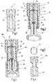
- Fig. 1an insert 13 is shown in longitudinal section, at the first a possible principle of the closure according to the invention is to be explained.
- the insert 13is made of a rubber-elastic material and has a sealing element 14 and a pressure element 20, which are connected to each other via an annular, elastically deformable region 18 to form a gap 42 therebetween.
- the sealing element 14is cylindrical and has a cylindrical cavity 16, which continues in a corresponding cylindrical cavity 22 of the same diameter in the pressure element 20.
- the annular, elastically deformable region 18represents a diameter taper between the two cavities 16, 22.
- the pressure element 20has a slightly smaller outer diameter than the sealing element 14 and is closed at its lower end by a recess 24 with a larger diameter than the cavity 22 , The pressure element 20 can be placed with the recess 24 on the distal end of a syringe body.
- distalis understood to mean the side of the syringe facing the patient or facing away from the user.
- Such an insert 13can now be used to seal the cannula of a syringe filled with a liquid.
- a relative movement between the sealing element 14 and the pressure element 20must be achieved either by an axial displacement or by a rotation between these two elements, whereby the inner diameter of the annular Area 18 is reduced and at the same time reduces the size of the gap 42 between the sealing member 14 and the pressure element 20.
- the inner diameter of the annular Area 18is reduced and at the same time reduces the size of the gap 42 between the sealing member 14 and the pressure element 20.
- the outer diameter of the sealing member 14is slightly larger than the outer diameter of the pressure member 20 to facilitate manipulation of the sealing member 14 by a closure cap of the closure to bring about the desired reduction in diameter.
- FIG. 2A first possible practical embodiment of a syringe according to the invention is shown in FIG. 2 and designated overall by the numeral 10.
- the syringe 10has a syringe body 26 made of glass, in the distal end of a cannula 28 is glued with an adhesive 32.
- a generally designated 12 closureTo close the syringe 10 at the distal end and to protect the cannula 28 is a generally designated 12 closure.
- the closure 12has an insert 13 of the type previously explained with reference to FIG. 1 with a sealing element 14 and a pressure element 20.
- the pressure element 20is provided on its side facing the syringe body 26 with a suitable recess, so that the pressure element 20 can be placed on a correspondingly shaped bead 36 at the end of the syringe body 26 and latched hereby.
- a projection 38which engages behind the bead 36.
- the insert 13is enclosed by a closure cap 34, by means of which the sealing element 14 is displaced somewhat in the direction of the pressure element 20.
- the closure cap 34In the closed position shown in FIG. 2, the closure cap 34 thus engages behind the proximal end of the pressure element 20 with a projection 40 projecting radially inward and engages it. In this way, the closure 12 can be locked securely in the closed position on the bead 36 of the syringe body 26.
- the gap 42 between the sealing element 14 and the pressure element 20is significantly reduced in comparison to the illustration according to FIG. 1, whereby the annular, elastically deformable region 18 seals against the outer surface of the cannula 28 invests.
- a liquid-tight seal of the cannula 28shortly behind the tip 30 of the cannula 28 through the annular region 18, a liquid-tight seal of the cannula 28, so that from the lumen of the syringe and the cannula 28 no liquid can escape to the outside.
- the tip 30 of the cannula 28is received without contact in the cavity 16 of the sealing element 14, so that damage to the tip 30 or contamination by piercing into the material of the sealing element 14 is reliably avoided.
- the cap 34has to be withdrawn to the outside and removed from the detent position.
- the seal member 14is moved outwardly so that the gap 42 between the seal member 14 and pressure member 20 increases and the closure 12 can be easily pulled off the cannula 28.
- FIG. 3A modification of the embodiment of FIG. 2 is shown in Fig. 3 and generally designated by the numeral 10 a.
- the syringe 10ais a plastic syringe in which the closure cap 34 is screwed into the distal end of the syringe body 26 with a Luer-lock thread 48.
- the cannula 28is glued into a correspondingly shaped recess at the distal end 44 of the syringe body 26 by means of an adhesive 32.
- the inner diameter of the annular region 18is reduced in this way, so that it bears sealingly behind the tip 30 of the cannula 28 on its outer surface and seals it in a liquid-tight manner in the closed position shown in FIG.
- the closure 12acan be easily released by unscrewing the luer-lock thread from the closed position so that the closure cap 34 can be pulled off to use the syringe.
- the closurein turn has an insert 13b which consists of a sealing element 14 and a pressure element 20, which are connected to one another via an annular, elastically deformable region 18.
- the sealing member 14may have approximately at its two outer surfaces flats 50 to allow easy rotation of the sealing element 14 by means of an attached cap.
- the syringe 10bhas a closure 12b with a closure cap 34, by means of which the sealing element 14 can be rotated relative to the pressure element 20. This leads to a reduction in the diameter of the annular region 18, by which the sealing element 14 and the pressure element 20 are connected to one another. Thus, the cannula 28 is again sealed in the vicinity of its tip 30 by the annular region 18.
- the closure cap 34is latched in the closed position shown in FIG. 6 with suitable latching elements 56 on associated latching elements 54 of a fastening element held on the distal end 44 of the syringe body 26.
- a safeguard against removal to the outsidecan be frictionally ensured in the simplest case, or possibly by further locking elements (not shown).
- FIG. 10A further embodiment of a syringe 10c according to the invention with a closure 12c according to the invention is shown in FIG.
- the closure 12cin this case again has a sealing element 14 and a pressure element 20, which are connected to one another via an elastically deformable, annular region 18.
- the pressure element 20is placed at its proximal end on a bead 36 of the syringe body 26 and locked with this.
- a cap 68is pushed from the outside and locked at the proximal end of the pressure element 20 with this.
- the closure cap 34surrounds the sealing element 14 on its outer side and has at its proximal end two folding brackets 58, which are connected via film hinges 60 on both sides with the closure cap 34 and are pivotable relative thereto.
- This folding bracket 58are passed through correspondingly shaped recesses of the attachment 68 and locked with their ends 64 in associated slots 66 of the attachment 68.
- the folding bracket 58engage in the closed position shown in Fig. 7 with corresponding radial projections 62 in the annular region 18 from the outside and press it onto the outer surface of the cannula 28th
- the closure cap 34is locked in the closed position shown in Fig. 7 with the ends 64 in the slots 66 that a release by peeling the cap 34 to the outside only after a corresponding destruction of the hinged bracket 58 is possible, which is visually recognizable.
Landscapes
- Health & Medical Sciences (AREA)
- Vascular Medicine (AREA)
- Engineering & Computer Science (AREA)
- Anesthesiology (AREA)
- Biomedical Technology (AREA)
- Heart & Thoracic Surgery (AREA)
- Hematology (AREA)
- Life Sciences & Earth Sciences (AREA)
- Animal Behavior & Ethology (AREA)
- General Health & Medical Sciences (AREA)
- Public Health (AREA)
- Veterinary Medicine (AREA)
- Infusion, Injection, And Reservoir Apparatuses (AREA)
Abstract
Description
Translated fromGermanDie Erfindung betrifft eine Spritze mit einem Verschluss, mit einer aus einem Spritzenkörper hervorstehenden Kanüle, deren Spitze in einer Schließstellung der Spritze von einer Verschlusskappe umschlossen ist, und mit einem Dichtungselement zur Abdichtung der Kanüle in der Schließstellung.The invention relates to a syringe with a closure, with a protruding from a syringe body cannula, the tip is enclosed in a closed position of the syringe by a closure cap, and with a sealing element for sealing the cannula in the closed position.
Die Erfindung betrifft ferner einen Verschluss für eine Spritze, die eine aus einem Spritzenkörper hervorstehende Kanüle aufweist, wobei der Verschluss zur Montage auf einem Ende des Spritzenkörpers ausgebildet ist und eine Verschlusskappe aufweist, die eine Spitze der Kanüle in einer Schließstellung umschließt, und mit einem Dichtungselement zur Abdichtung der Kanüle in der Schließstellung.The invention further relates to a closure for a syringe having a cannula projecting from a syringe body, the closure being adapted for mounting on an end of the syringe body and having a closure cap which encloses a tip of the cannula in a closed position and a sealing element for sealing the cannula in the closed position.
Eine derartige Spritze mit einem derartigen Verschluss ist bspw. aus der
Es handelt sich hierbei um eine Einmalspritze mit einer im Spritzenkörper fest aufgenommenen Injektionsnadel und mit einer Verschlusskappe zum Schutz der Injektionsnadel. Um eine Abdichtung der vorgefüllten Spritze zu gewährleisten, ist die Injektionsnadel in ein Dichtungselement eingestochen, das von der Verschlusskappe umschlossen ist.This is a disposable syringe with an injection needle firmly held in the syringe body and with a cap to protect the injection needle. In order to ensure a seal of the pre-filled syringe, the injection needle is inserted into a sealing element which is enclosed by the closure cap.
Ähnliche Spritzen sind aus der
Die im Stand der Technik bekannten Spritzen werden mit flüssigen Substanzen befüllt und durch eine Kappe verschlossen, die man im internationalen Sprachgebrauch meist als "needle shield" bezeichnet. Sie besteht in der Regel aus einem gummielastischen Material, meist einem mineralgefüllten Synthesekautschuk mit einer Shore-Härte zwischen 40 A und 60 A. Um diese Verschlusskappen mechanisch stabiler zu machen, werden sie oft in ein festes Gehäuse eingebaut. Eine derartige Ausführungsform bezeichnet man dann als "rigid needle shield". Spritzen und Verschlüsse der eingangs genannten Art erfüllen grundsätzlich zwei wesentliche Funktionen. Zum einen verdecken sie die Spitze der in den Spritzenkörper eingebauten Kanüle, zum anderen verschließen sie distal den Innenraum des Spritzenkörpers in einer flüssigkeitsdichten Weise. Dies geschieht auf einfache Weise dadurch, dass die Kanülenspitze in das weiche Material der Schutzkappe eingestochen wird.The known in the art syringes are filled with liquid substances and sealed by a cap, which is usually referred to in international usage as a "needle shield". It is usually made of a rubber-elastic material, usually a mineral-filled synthetic rubber with a Shore hardness between 40 A and 60 A. To make these caps mechanically stable, they are often installed in a solid housing. Such an embodiment is referred to as a "rigid needle shield". Syringes and closures of the type mentioned initially meet two essential functions. On the one hand they cover the tip of the cannula built into the syringe body, on the other hand they seal the interior of the syringe body distally in a liquid-tight manner. This is done in a simple manner in that the cannula tip is inserted into the soft material of the protective cap.
Diese Art der Abdichtung ist mit erheblichen Nachteilen für die Spritze und letztlich für die Patienten verbunden, die mit dieser Spritze behandelt werden. Insbesondere dünnwandige Kanülen mit geringen Außendurchmessern, wie sie heutzutage für vorgefüllte Spritzen meist verwendet werden, besitzen einen mechanisch äußerst empfindlichen Schliff. Je filigraner die Kanüle, desto anfälliger ist der Schliff für Beschädigungen. Eine Kanüle, die einmal in ein beliebiges Medium eingestochen wurde, kann bereits einen Teil ihrer Schärfe eingebüßt haben. In manchen Fällen kann es selbst beim Einstich in sehr weiche Medien zu einer häkelnadelartigen Deformation der Kanülenspitze kommen. Die Verwendung nicht optimal scharfer und an der Spitze deformierter Kanülen führt jedoch beim Patienten zu einer erheblichen Erhöhung des Punktionsschmerzes. Auch besteht die Gefahr, dass durch verformte Kanülenschliffe Blutungen, Hämatome oder sogar Abszesse entstehen. Ferner ist es seit Langem bekannt, dass beim Einstechen von Kanülen in gummielastische Materialien Partikel ausgestanzt werden, die im schlimmsten Fall die Kanüle verstopfen und die Injektion des Medikaments verhindern können. Bleiben sie dagegen beweglich, können sie mit der Injektion in den Patienten gespült werden.This type of seal involves considerable disadvantages for the syringe and ultimately for the patients being treated with this syringe. In particular, thin-walled cannulas with small outer diameters, as they are usually used today for prefilled syringes, have a mechanically extremely sensitive cut. The more filigree the cannula, the more susceptible the cut is to damage. A cannula, once inserted into any medium has already lost some of its sharpness. In some cases, even when punctured in very soft media, a crochet needle-like deformation of the cannula tip may occur. However, the use of non-optimally sharp and tip-deformed cannulas results in a significant increase in puncture pain in the patient. There is also the danger that deformed cannulae may cause bleeding, hematomas or even abscesses. Furthermore, it has been known for a long time that when piercing cannulas into rubber-elastic materials, particles are punched out which in the worst case can clog the cannula and prevent the injection of the medicament. If they remain mobile, they can be flushed with the injection into the patient.
Der Erfindung liegt somit die Aufgabe zu Grunde, eine verbesserte Spritze und einen verbesserten Verschluss für eine Spritze zu schaffen, womit ein sicherer Verschluss einer vorgefüllten Spritze ermöglicht ist, ohne dass die Spitze der Kanüle in ein Dichtungsmaterial eingestochen wird.The invention is therefore based on the object to provide an improved syringe and an improved closure for a syringe, whereby a secure closure of a prefilled syringe is made possible without the tip of the cannula is pierced in a sealing material.
Diese Aufgabe wird erfindungsgemäß bei einer Spritze gemäß der eingangs genannten Art dadurch gelöst, dass das Dichtungselement einen ringförmigen, elastisch verformbaren Bereich aufweist, der mittels der Verschlusskappe an die Außenoberfläche der Kanüle dichtend anpressbar ist.This object is achieved in a syringe according to the type mentioned fact that the sealing element has an annular, elastically deformable region which is sealingly pressed by means of the cap to the outer surface of the cannula.
Die Aufgabe der Erfindung wird ferner bei einem Verschluss der eingangs genannten Art dadurch gelöst, dass das Dichtungselement einen ringförmigen, elastisch verformbaren Bereich aufweist, der mittels der Verschlusskappe an die Außenoberfläche der Kanüle dichtend anpressbar ist.The object of the invention is further achieved in a closure of the type mentioned above in that the sealing element has an annular, elastically deformable region which is sealingly compressible by means of the closure cap to the outer surface of the cannula.
Die Aufgabe der Erfindung wird auf diese Weise vollkommen gelöst.The object of the invention is completely solved in this way.
Erfindungsgemäß wird nämlich jegliches Einstechen der Spitze der Kanüle in ein Dichtungselement vermieden. Vielmehr erfolgt eine flüssigkeitsdichte Abdichtung der Kanüle am distalen Ende dadurch, dass der ringförmige, elastisch verformbare Bereich in der Schließstellung dichtend an die Außenoberfläche der Kanüle anpressbar ist. Auf diese Weise können die im Stand der Technik vorhandenen Nachteile vermieden werden. Insbesondere kann jegliche Berührung der Spitze der Kanüle mit dem Dichtungsmaterial vermieden werden. So kann keine Deformation der Spitze erfolgen. Gleichfalls wird ein Stanzeffekt vermieden, so dass kein durch Einstechen der Kanüle in ein Dichtungsmaterial ausgestanztes Fremdmaterial zu einer Kontamination beitragen kann.In fact, according to the invention, any piercing of the tip of the cannula into a sealing element is avoided. Rather, a liquid-tight seal of the cannula at the distal end takes place in that the annular, elastically deformable Area in the closed position is sealingly pressed against the outer surface of the cannula. In this way, the disadvantages existing in the prior art can be avoided. In particular, any contact of the tip of the cannula with the sealing material can be avoided. So no deformation of the tip can take place. Likewise, a punching effect is avoided, so that no foreign material punched out by piercing the cannula into a sealing material can contribute to contamination.
In einer vorteilhaften Weiterbildung der Erfindung weist das Dichtungselement einen Hohlraum auf, in dem die Spitze der Kanüle in der Schließstellung vorzugsweise berührungsfrei aufgenommen ist.In an advantageous development of the invention, the sealing element has a cavity in which the tip of the cannula is preferably received without contact in the closed position.
Auf diese Weise wird die Gefahr einer möglichen Kontamination der Spritze im Bereich der Spitze der Kanüle weiter verringert.In this way, the risk of possible contamination of the syringe in the region of the tip of the cannula is further reduced.
Gemäß einer weiteren Ausgestaltung der Erfindung ist das Dichtungselement über den ringförmigen Bereich mit einem Druckelement verbunden, wobei der ringförmige Bereich durch eine Relativbewegung zwischen Dichtelement und Druckelement auf die Außenoberfläche der Kanüle anpressbar ist.According to a further embodiment of the invention, the sealing element is connected via the annular region with a pressure element, wherein the annular region can be pressed by a relative movement between the sealing element and pressure element on the outer surface of the cannula.
Auf diese Weise kann eine saubere Abdichtung der Spritze nach einem Füllvorgang gewährleistet werden, indem nach Beendigung eines Füllvorgangs der Spritze das Dichtelement und das Druckelement relativ zueinander bewegt werden, um den ringförmigen Bereich auf die Außenoberfläche der Kanüle anzupressen.In this way, a clean seal of the syringe after a filling operation can be ensured by, after completion of a filling operation of the syringe, the sealing element and the pressure element are moved relative to each other to press the annular area on the outer surface of the cannula.
Gemäß einer weiteren Ausgestaltung der Erfindung ist zumindest das Dichtungselement von der Verschlusskappe zumindest teilweise umschlossen und mittels der Verschlusskappe relativ zum Druckelement bewegbar.According to a further embodiment of the invention, at least the sealing element is at least partially enclosed by the closure cap and movable relative to the pressure element by means of the closure cap.
So kann durch eine Bewegung der Verschlusskappe relativ zum Druckelement das Dichtungselement durch die Verschlusskappe bewegt werden, um eine Abdichtung des ringförmigen Bereiches zu erreichen.Thus, by a movement of the closure cap relative to the pressure element, the sealing element can be moved through the closure cap in order to achieve a sealing of the annular region.
Gemäß einer weiteren Ausgestaltung der Erfindung sind das Dichtelement und das Druckelement axial zueinander beweglich.According to a further embodiment of the invention, the sealing element and the pressure element are axially movable relative to each other.
Zusätzlich oder alternativ können das Dichtelement und das Druckelement gegeneinander verdrehbar sein.Additionally or alternatively, the sealing element and the pressure element can be rotated against each other.
So kann durch eine Axialbewegung oder durch eine Drehbewegung zwischen Dichtungselement und Druckelement eine Anpressung des ringförmigen Bereiches auf die Außenoberfläche der Kanüle erreicht werden.Thus, by an axial movement or by a rotational movement between the sealing element and pressure element, a contact pressure of the annular region can be achieved on the outer surface of the cannula.
Gemäß einer weiteren Ausgestaltung der Erfindung ist die Verschlusskappe in der Schließstellung verrastbar.According to a further embodiment of the invention, the closure cap can be latched in the closed position.
Dies ist eine besonders einfache Möglichkeit, um die Verschlusskappe in der Schließstellung in befülltem Zustand der Spritze gegen ein unbeabsichtigtes Öffnen zu sichern.This is a particularly simple way to secure the cap in the closed position in the filled state of the syringe against accidental opening.
Gemäß einer weiteren Ausgestaltung der Erfindung ist am distalen Ende des Spritzenkörpers ein Wulst vorgesehen, an dem die Verschlusskappe oder das Druckelement in der Schließstellung befestigt ist.According to a further embodiment of the invention, a bead is provided at the distal end of the syringe body, to which the closure cap or the pressure element is fixed in the closed position.
Auf diese Weise ist eine einfache Befestigung der Verschlusskappe am Spritzenkörper ermöglicht.In this way, a simple attachment of the cap on the syringe body is possible.
Gemäß einer weiteren Ausgestaltung der Erfindung ist die Verschlusskappe mittels eines Gewindes, vorzugsweise mittels eines Luer-Lock-Gewindes, am Spritzenkörper festlegbar.According to a further embodiment of the invention, the closure cap can be fixed to the syringe body by means of a thread, preferably by means of a Luer-Lock thread.
Auch auf diese weise kann eine einfache Sicherung der Verschlusskappe in der Schließstellung erreicht werden.In this way, a simple backup of the cap can be achieved in the closed position.
Gemäß einer weiteren Ausgestaltung der Erfindung ist ein Indikatorelement vorgesehen, das eine erstmalige Bewegung der Verschlusskappe aus der Schließstellung anzeigt.According to a further embodiment of the invention, an indicator element is provided which indicates a first-time movement of the closure cap from the closed position.
So kann eine vormalige Betätigung der Spritze optisch erkennbar gemacht werden, um sicherzustellen, dass nur eine Spritze verwendet wird, bei der sich die Verschlusskappe noch in der Schließstellung mit der Originalbefüllung befindet.Thus, a previous operation of the syringe can be made visually recognizable to ensure that only one syringe is used, in which the cap is still in the closed position with the original filling.
Gemäß einer weiteren Ausgestaltung der Erfindung weist die Verschlusskappe eine Schnappverbindung mit Bügelelementen auf, die in der Schließstellung den ringförmigen Bereich auf die Außenoberfläche der Kanüle pressen.According to a further embodiment of the invention, the closure cap has a snap connection with stirrup elements, which in the closed position press the annular area onto the outer surface of the cannula.
Auf diese Weise wird die Abdichtung der Kanüle weiter verbessert.In this way, the sealing of the cannula is further improved.
In zusätzlicher Weiterbildung dieser Ausgestaltung ist die Schnappverbindung als nicht zerstörungsfrei lösbare Schnappverbindung ausgebildet, bei der eine erstmalige Bewegung der Verschlusskappe aus der Schließstellung optisch erkennbar ist.In an additional development of this embodiment, the snap connection is designed as a non-destructive releasable snap connection, in which a first-time movement of the closure cap from the closed position is visually recognizable.
Auf diese Weise kann die optische Anzeige einer erstmaligen Bewegung der Verschlusskappe aus der Schließstellung mit einfachen Mitteln verwirklicht werden.In this way, the visual indication of a first movement of the closure cap from the closed position can be realized with simple means.
Gemäß einer weiteren Ausgestaltung der Erfindung bestehen das Dichtungselement und das Druckelement aus demselben Material und sind einstückig ausgebildet.According to a further embodiment of the invention, the sealing element and the pressure element made of the same material and are integrally formed.
Auf diese Weise kann eine Durchmesserverringerung im ringförmigen Bereich zwecks Abdichtung der Kanüle an der Außenoberfläche durch eine Relativbewegung zwischen Dichtungselement und Druckelement auf besonders einfache Weise erzielt werden.In this way, a reduction in diameter in the annular region for the purpose of sealing the cannula on the outer surface can be achieved in a particularly simple manner by a relative movement between the sealing element and the pressure element.
Es versteht sich, dass die vorstehend genannten und die nachstehend noch zu erläuternden Merkmale der Erfindung nicht nur in der jeweils angegebenen Kombination, sondern auch in anderen Kombinationen oder in Alleinstellung verwendbar sind, ohne den Rahmen der Erfindung zu verlassen.It is understood that the features of the invention mentioned above and those yet to be explained below can be used not only in the particular combination indicated, but also in other combinations or in isolation, without departing from the scope of the invention.
Weitere Merkmale und Vorteile der Erfindung ergeben sich aus der nachfolgenden Beschreibung bevorzugter Ausführungsbeispiele unter Bezugnahme auf die Zeichnung. Es zeigen:
- Fig. 1
- einen Längsschnitt durch einen Einsatz mit einem Dichtungselement und einem Druckelement, der für einen erfindungsgemäßen Verschluss verwendet werden kann;
- Fig. 2
- eine praktische Anwendung des Einsatzes gemäß Fig. 1 bei einer ersten Ausführung eines erfindungsgemäßen Verschlusses am Beispiel einer Glasspritze mit eingeklebter Kanüle, in längsgeschnittener Darstellung;
- Fig. 3
- eine Abwandlung der Ausführung gemäß Fig. 2 in einer Ausgestaltung als Kunststoffspritze, wobei die Verschlusskappe in ein Luer-Lock-Gewinde geschraubt wird;
- Fig. 4
- eine Abwandlung des Einsatzes gemäß Fig. 1 im Längsschnitt, wobei das Dichtungselement und das Druckelement relativ zueinander verdrehbar sind;
- Fig. 5
- eine Aufsicht des Einsatzes gemäß Fig. 4;
- Fig. 6
- eine praktische Anwendung des Einsatzes gemäß der
Figuren 4 und 5 bei einer Spritze aus Glas mit einem drehmäßig verrastbaren Verschluss; und - Fig. 7
- eine weitere Abwandlung einer erfindungsgemäßen Spritze mit einem in einer Schließstellung verrastbaren Verschluss mit einer Schnappverbindung, der beim Lösen aus der Schließstellung zerstört wird und somit als Indikationselement für ein erstmaliges Öffnen des Verschlusses dient.
- Fig. 1
- a longitudinal section through an insert with a sealing element and a pressure element, which can be used for a closure according to the invention;
- Fig. 2
- a practical application of the insert of Figure 1 in a first embodiment of a closure according to the invention on the example of a glass syringe with glued cannula, in longitudinal section.
- Fig. 3
- a modification of the embodiment of Figure 2 in an embodiment as a plastic syringe, wherein the cap is screwed into a Luer-lock thread.
- Fig. 4
- a modification of the insert according to Figure 1 in longitudinal section, wherein the sealing element and the pressure element are rotatable relative to each other.
- Fig. 5
- a plan view of the insert of FIG. 4;
- Fig. 6
- a practical application of the insert according to Figures 4 and 5 in a syringe made of glass with a rotationally lockable closure; and
- Fig. 7
- a further modification of a syringe according to the invention with a latchable in a closed position closure with a snap connection, which is destroyed upon release from the closed position and thus serves as an indication element for a first-time opening of the closure.
In Fig. 1 ist ein Einsatz 13 in längsgeschnittener Darstellung dargestellt, an dem zunächst ein mögliches Prinzip des erfindungsgemäßen Verschlusses erläutert werden soll.In Fig. 1, an
Der Einsatz 13 besteht aus einem gummielastischen Material und weist ein Dichtungselement 14 und ein Druckelement 20 auf, die über einen ringförmigen, elastisch verformbaren Bereich 18 unter Bildung eines Spaltes 42 dazwischen miteinander verbunden sind. Das Dichtungselement 14 ist zylindrisch ausgebildet und weist einen zylindrischen Hohlraum 16 auf, der sich in einem entsprechenden zylindrischen Hohlraum 22 mit gleichem Durchmesser im Druckelement 20 fortsetzt. Der ringförmige, elastisch verformbare Bereich 18 stellt eine Durchmesserverjüngung zwischen den beiden Hohlräumen 16, 22 dar. Das Druckelement 20 weist einen etwas geringeren Außendurchmesser als das Dichtungselement 14 auf und ist an seinem unteren Ende durch eine Ausnehmung 24 mit größerem Durchmesser als der Hohlraum 22 abgeschlossen. Das Druckelement 20 kann mit der Ausnehmung 24 auf das distale Ende eines Spritzenkörpers aufgesetzt werden.The
Unter "distal" wird in dieser Anmeldung die dem Patienten zugewandte bzw. dem Benutzer abgewandte Seite der Spritze verstanden.In this application, "distal" is understood to mean the side of the syringe facing the patient or facing away from the user.
Ein derartiger Einsatz 13 kann nun zur Abdichtung der Kanüle einer mit einer Flüssigkeit befüllten Spritze verwendet werden. Hierzu muss lediglich eine Relativbewegung zwischen dem Dichtungselement 14 und dem Druckelement 20 entweder durch eine Axialverschiebung oder durch ein Verdrehen zwischen diesen beiden Elementen erreicht werden, wodurch sich der Innendurchmesser des ringförmigen Bereiches 18 verringert und sich gleichzeitig die Größe des Spaltes 42 zwischen dem Dichtungselement 14 und dem Druckelement 20 verkleinert. Durch eine entsprechende Verringerung des Innendurchmessers des ringförmigen Bereiches 18 legt sich dieser an die Außenoberfläche einer Kanüle der Spritze an und kann diese flüssigkeitsdicht abdichten.Such an
Auf diese Weise kann ein sicherer Verschluss einer mit einem Pharmazeutikum gefüllten Spritze aus Glas oder Kunststoff auf der distalen Seite erreicht werden, damit die enthaltene Flüssigkeit nicht austreten kann, auch nicht nach einer Lagerzeit von mehreren Jahren.In this way, a secure closure of a pharmaceutical-filled syringe made of glass or plastic on the distal side can be achieved so that the liquid contained can not escape, even after a storage period of several years.
Zweckmäßigerweise ist der Außendurchmesser des Dichtungselementes 14 etwas größer als der Außendurchmesser des Druckelementes 20, um eine Manipulation des Dichtungselementes 14 durch eine Verschlusskappe des Verschlusses zu erleichtern, um die gewünschte Durchmesserverringerung herbeizuführen.Conveniently, the outer diameter of the sealing
Eine erste mögliche praktische Ausführung einer erfindungsgemäßen Spritze ist in Fig. 2 dargestellt und insgesamt mit der Ziffer 10 bezeichnet.A first possible practical embodiment of a syringe according to the invention is shown in FIG. 2 and designated overall by the numeral 10.
Die Spritze 10 weist einen aus Glas bestehenden Spritzenkörper 26 auf, in dessen distales Ende eine Kanüle 28 mit einem Kleber 32 eingeklebt ist. Zum Verschluss der Spritze 10 am distalen Ende und zum Schutz der Kanüle 28 dient ein insgesamt mit 12 bezeichneter Verschluss. Der Verschluss 12 weist einen Einsatz 13 der zuvor anhand von Fig. 1 erläuterten Art mit einem Dichtungselement 14 und einem Druckelement 20 auf. Das Druckelement 20 ist an seiner, dem Spritzenkörper 26 zugewandten Seite mit einer geeigneten Ausnehmung versehen, so dass das Druckelement 20 auf einen entsprechend geformten Wulst 36 am Ende des Spritzenkörpers 26 aufgesetzt und hiermit verrastet werden kann. Zur Verrastung dient ein Vorsprung 38, der den Wulst 36 hintergreift.The
Der Einsatz 13 ist von einer Verschlusskappe 34 umschlossen, mittels derer das Dichtungselement 14 etwas in Richtung auf das Druckelement 20 verschoben ist. In der in Fig. 2 gezeigten Schließstellung hintergreift so die Verschlusskappe 34 mit einem radial nach innen hervorstehenden Vorsprung 40 das proximale Ende des Druckelementes 20 und rastet daran ein. Auf diese Weise kann der Verschluss 12 in der Schließstellung am Wulst 36 des Spritzenkörpers 26 sicher verrastet werden.The
Durch die Axialverschiebung des Dichtungselementes 14 in Richtung auf das Druckelement 20 ist der Spalt 42 zwischen Dichtungselement 14 und Druckelement 20 im Vergleich zu der Darstellung gemäß Fig. 1 deutlich verkleinert, wodurch der ringförmige, elastisch verformbare Bereich 18 sich auf die Außenoberfläche der Kanüle 28 dichtend anlegt. So erfolgt kurz hinter der Spitze 30 der Kanüle 28 durch den ringförmigen Bereich 18 eine flüssigkeitsdichte Abdichtung der Kanüle 28, so dass aus dem Lumen der Spritze und der Kanüle 28 keine Flüssigkeit nach außen gelangen kann.As a result of the axial displacement of the sealing
Hierbei ist die Spitze 30 der Kanüle 28 im Hohlraum 16 des Dichtungselementes 14 berührungsfrei aufgenommen, so dass eine Beschädigung der Spitze 30 oder eine Kontamination durch Einstechen in das Material des Dichtungselementes 14 sicher vermieden wird. Zur Benutzung der Spritze 10 muss lediglich die Verschlusskappe 34 nach außen abgezogen und aus der Raststellung entfernt werden. Während der Abziehbewegung wird das Dichtungselement 14 nach außen bewegt, so dass sich der Spalt 42 zwischen Dichtungselement 14 und Druckelement 20 vergrößert und der Verschluss 12 leicht von der Kanüle 28 abgezogen werden kann.Here, the
Eine Abwandlung der Ausführung gemäß Fig. 2 ist in Fig. 3 dargestellt und insgesamt mit der Ziffer 10a bezeichnet.A modification of the embodiment of FIG. 2 is shown in Fig. 3 and generally designated by the numeral 10 a.
Hierbei werden, wie auch bei den nachfolgenden Ausführungen, für entsprechende Teile entsprechende Bezugsziffern verwendet.Here, as in the following remarks, corresponding reference numerals are used for corresponding parts.
Bei der Spritze 10a handelt es sich um eine Kunststoffspritze, bei der die Verschlusskappe 34 mit einem Luer-Lock-Gewinde 48 in das distale Ende des Spritzenkörpers 26 eingeschraubt ist. Die Kanüle 28 ist in eine entsprechend geformte Ausnehmung am distalen Ende 44 des Spritzenkörpers 26 mittels eines Klebers 32 eingeklebt. Durch eine Drehbewegung der Verschlusskappe 34 kann beim Verschluss 12a das Dichtungselement 14 in Axialrichtung zum Druckelement 20 hin bewegt werden, um, wie zuvor anhand von Fig. 2 beschrieben, den Spalt 42 zwischen Dichtungselement 14 und Druckelement 20 zu verkleinern.The
Wie bei der Ausführung gemäß Fig. 2 wird auf diese Weise der Innendurchmesser des ringförmigen Bereiches 18 verkleinert, so dass sich dieser kurz hinter der Spitze 30 der Kanüle 28 auf deren Außenoberfläche dichtend anlegt und diese in der in Fig. 3 dargestellten Schließstellung flüssigkeitsdicht abdichtet. Der Verschluss 12a kann leicht durch Aufschrauben des Luer-Lock-Gewindes aus der Schließstellung gelöst werden, so dass die Verschlusskappe 34 abgezogen werden kann, um die Spritze zu benutzen.As in the embodiment according to FIG. 2, the inner diameter of the
Eine weitere Variante des erfindungsgemäßen Verschlusses wird im Folgenden anhand der Figuren 4 bis 6 näher erläutert. Der Verschluss weist wiederum einen Einsatz 13b auf, der aus einem Dichtungselement 14 und einem Druckelement 20 besteht, die über einen ringförmigen, elastisch verformbaren Bereich 18 miteinander verbunden sind.A further variant of the closure according to the invention is explained in more detail below with reference to FIGS. 4 to 6. The closure in turn has an
Im Unterschied zu den zuvor erläuterten Ausführungen kann hierbei eine Durchmesserverringerung des ringförmigen Bereiches 18 nicht durch ein Zusammendrücken, sondern durch ein Verdrehen erreicht werden. Indem das Dichtungselement 14 und das Druckelement 20 gegeneinander verdreht werden, ergibt sich eine Durchmesserverringerung des ringförmigen Bereiches 18, um eine Abdichtung einer zuvor eingeführten Kanüle in diesem Bereich zu erzielen. Wie aus Fig. 5 zu ersehen ist, kann das Dichtungselement 14 etwa an seinen beiden Außenflächen Abflachungen 50 aufweisen, um ein einfaches Verdrehen des Dichtungselementes 14 mit Hilfe einer aufgesetzten Verschlusskappe zu ermöglichen.In contrast to the previously explained embodiments, in this case a reduction in the diameter of the
Eine derartige Ausführung einer solchen Spritze mit einem solchen Verschluss in Fig. 6 dargestellt und insgesamt mit 10b bezeichnet. Die Spritze 10b weist einen Verschluss 12b mit einer Verschlusskappe 34 auf, mittels derer das Dichtungselement 14 relativ zum Druckelement 20 verdreht werden kann. Dies führt zu einer Durchmesserverringerung des ringförmigen Bereiches 18, durch den das Dichtungselement 14 und das Druckelement 20 miteinander verbunden sind. So wird die Kanüle 28 wiederum in der Nähe ihrer Spitze 30 durch den ringförmigen Bereich 18 abgedichtet. Die Verschlusskappe 34 ist in der in Fig. 6 dargestellten Schließstellung mit geeigneten Rastelementen 56 an zugeordneten Rastelementen 54 eines auf dem distalen Ende 44 des Spritzenkörpers 26 gehaltenen Befestigungselement verrastet. Eine Sicherung gegen ein Abziehen nach außen kann im einfachsten Fall reibschlüssig gewährleistet werden oder etwadurch weitere Rastelemente (nicht dargestellt).Such an embodiment of such a syringe with such a closure shown in Fig. 6 and indicated generally at 10b. The
Eine weitere Ausführung einer erfindungsgemäßen Spritze 10c mit einem erfindungsgemäßen Verschluss 12c ist in Fig. 7 dargestellt.A further embodiment of a syringe 10c according to the invention with a
Der Verschluss 12c weist hierbei wiederum ein Dichtungselement 14 und ein Druckelement 20 auf, die über einen elastisch verformbaren, ringförmigen Bereich 18 miteinander verbunden sind. Das Druckelement 20 ist an seinem proximalen Ende auf einen Wulst 36 des Spritzenkörpers 26 aufgesetzt und mit diesem verrastet. Über das Druckelement 20 ist ein Aufsatz 68 von außen aufgeschoben und am proximalen Ende des Druckelementes 20 mit diesem verrastet.The
Die Verschlusskappe 34 umschließt das Dichtungselement 14 an seiner Außenseite und weist an ihrem proximalen Ende zwei Klappbügel 58 auf, die über Filmscharniere 60 an beiden Seiten mit der Verschlusskappe 34 verbunden sind und relativ zu dieser verschwenkbar sind. Diese Klappbügel 58 sind durch entsprechend geformte Ausnehmungen des Aufsatzes 68 hindurchgeführt und mit ihren Enden 64 in zugeordnete Schlitze 66 des Aufsatzes 68 eingerastet. Die Klappbügel 58 greifen in der in Fig. 7 dargestellten Schließstellung mit entsprechenden radialen Vorsprüngen 62 in den ringförmigen Bereich 18 von außen ein und pressen diesen auf die Außenoberfläche der Kanüle 28.The
Die Verschlusskappe 34 ist in der in Fig. 7 gezeigten Schließstellung derart mit den Enden 64 in den Schlitzen 66 verrastet, dass ein Lösen durch ein Abziehen der Verschlusskappe 34 nach außen nur nach einer entsprechenden Zerstörung der Klappbügel 58 ermöglicht ist, was optisch erkennbar ist.The
Auf diese Weise ist ein Originalitätsverschluss gewährleistet, da ein erstmaliges Abziehen der Verschlusskappe 34 aus der Schließstellung heraus zu einer Zerstörung der Klappbügel 58 im Bereich ihrer Enden 64 führt.In this way, a tamper-evident closure is ensured, since a first-time removal of the
Claims (26)
Translated fromGermanApplications Claiming Priority (1)
| Application Number | Priority Date | Filing Date | Title |
|---|---|---|---|
| DE102005058133ADE102005058133A1 (en) | 2005-11-30 | 2005-11-30 | Syringe, has sealing element and syringe body whereby annular, flexible deformable area can be pressed in sealing manner, by means of closing cap, on outer surface of cannula |
Publications (1)
| Publication Number | Publication Date |
|---|---|
| EP1795220A1true EP1795220A1 (en) | 2007-06-13 |
Family
ID=37858999
Family Applications (1)
| Application Number | Title | Priority Date | Filing Date |
|---|---|---|---|
| EP06023871AWithdrawnEP1795220A1 (en) | 2005-11-30 | 2006-11-17 | Syringe with cap |
Country Status (3)
| Country | Link |
|---|---|
| US (1) | US7641636B2 (en) |
| EP (1) | EP1795220A1 (en) |
| DE (1) | DE102005058133A1 (en) |
Cited By (4)
| Publication number | Priority date | Publication date | Assignee | Title |
|---|---|---|---|---|
| FR2913200A1 (en)* | 2007-03-02 | 2008-09-05 | Becton Dickinson France Soc Pa | NEEDLE PROTECTION DEVICE |
| EP2913076A4 (en)* | 2012-10-25 | 2016-08-17 | Taisei Kako Co | SYRINGE |
| US10183123B2 (en) | 2013-03-01 | 2019-01-22 | Aptar Stelmi Sas | Needle protection device |
| US10973985B2 (en) | 2013-03-01 | 2021-04-13 | Aptar Stelmi Sas | Injection device having a needle protection device |
Families Citing this family (80)
| Publication number | Priority date | Publication date | Assignee | Title |
|---|---|---|---|---|
| JP4994775B2 (en) | 2006-10-12 | 2012-08-08 | 日本コヴィディエン株式会社 | Needle point protector |
| DK2240222T3 (en) | 2008-01-11 | 2018-06-25 | Ucb Biopharma Sprl | SYSTEMS FOR THE ADMINISTRATION OF PHARMACEUTICALS FOR PATIENTS WITH RHEUMATOID ARTHRITIS |
| USD641078S1 (en) | 2008-12-29 | 2011-07-05 | Ucb Pharma, S.A. | Medical syringe with needle tip cap |
| EP3581223B1 (en) | 2008-07-18 | 2024-07-10 | UCB Biopharma SRL | Systems for automatically administering medication |
| DE202008010494U1 (en) | 2008-08-06 | 2008-11-20 | Beier, Wolfram, Prof. Dr. | Medical syringe with safety device |
| EP2251454B1 (en) | 2009-05-13 | 2014-07-23 | SiO2 Medical Products, Inc. | Vessel coating and inspection |
| WO2013170052A1 (en) | 2012-05-09 | 2013-11-14 | Sio2 Medical Products, Inc. | Saccharide protective coating for pharmaceutical package |
| USD660958S1 (en) | 2009-07-20 | 2012-05-29 | Ucb Pharma, S.A. | Device for administering medication |
| EP2374497B1 (en)* | 2010-04-08 | 2016-10-19 | West Pharmaceutical Services Deutschland GmbH & Co. KG | Syringe tip cap having fluoropolymer coated insert |
| US11624115B2 (en) | 2010-05-12 | 2023-04-11 | Sio2 Medical Products, Inc. | Syringe with PECVD lubrication |
| US8348895B1 (en)* | 2010-05-27 | 2013-01-08 | Medical Device Engineering, LLC. | Tamper evident cap assembly |
| US9402967B1 (en) | 2010-05-27 | 2016-08-02 | Medical Device Engineering, Llc | Tamper evident cap assembly |
| EP2585145B1 (en) | 2010-08-19 | 2014-03-05 | West Pharmaceutical Services, Inc. | Rigid needle shield |
| US9878101B2 (en) | 2010-11-12 | 2018-01-30 | Sio2 Medical Products, Inc. | Cyclic olefin polymer vessels and vessel coating methods |
| US8864708B1 (en) | 2010-12-03 | 2014-10-21 | Medical Device Engineering, LLC. | Tamper indicating closure assembly |
| US8591462B1 (en) | 2011-04-26 | 2013-11-26 | Medical Device Engineering, LLC. | Assembly and system for connecting a closure to a syringe |
| ES2662356T3 (en) | 2011-04-27 | 2018-04-06 | Kpr U.S., Llc | Safety IV catheter assemblies |
| USD655001S1 (en) | 2011-05-10 | 2012-02-28 | West Pharmaceutical Services Deutschland Gmbh & Co. Kg | Needle shield |
| WO2013048975A1 (en) | 2011-09-26 | 2013-04-04 | Covidien Lp | Safety catheter |
| EP2760521B1 (en) | 2011-09-26 | 2016-01-06 | Covidien LP | Safety iv catheter and needle assembly |
| US8834422B2 (en) | 2011-10-14 | 2014-09-16 | Covidien Lp | Vascular access assembly and safety device |
| CA2855353C (en) | 2011-11-11 | 2021-01-19 | Sio2 Medical Products, Inc. | Passivation, ph protective or lubricity coating for pharmaceutical package, coating process and apparatus |
| US11116695B2 (en) | 2011-11-11 | 2021-09-14 | Sio2 Medical Products, Inc. | Blood sample collection tube |
| FR2985669B1 (en) | 2012-01-12 | 2015-10-02 | Biocorp Rech Et Dev | DEVICE FOR PROTECTING THE NEEDLE OF A SYRINGE |
| US20150297800A1 (en) | 2012-07-03 | 2015-10-22 | Sio2 Medical Products, Inc. | SiOx BARRIER FOR PHARMACEUTICAL PACKAGE AND COATING PROCESS |
| US9311592B1 (en) | 2012-08-31 | 2016-04-12 | Medical Device Engineering, LLC. | Support and closure assembly for discharge port of a syringe and tracking system therefore |
| US9664626B2 (en) | 2012-11-01 | 2017-05-30 | Sio2 Medical Products, Inc. | Coating inspection method |
| US9903782B2 (en) | 2012-11-16 | 2018-02-27 | Sio2 Medical Products, Inc. | Method and apparatus for detecting rapid barrier coating integrity characteristics |
| AU2013352436B2 (en) | 2012-11-30 | 2018-10-25 | Sio2 Medical Products, Inc. | Controlling the uniformity of PECVD deposition on medical syringes, cartridges, and the like |
| US9764093B2 (en) | 2012-11-30 | 2017-09-19 | Sio2 Medical Products, Inc. | Controlling the uniformity of PECVD deposition |
| FR3002741B1 (en)* | 2013-03-01 | 2016-01-08 | Transformation Des Elastomeres A Usages Medicaux Et Ind Soc D | NEEDLE PROTECTION DEVICE. |
| US9821152B1 (en) | 2013-03-04 | 2017-11-21 | Medical Device Engineering, LLC. | Closure assembly |
| JP6453841B2 (en) | 2013-03-11 | 2019-01-16 | エスアイオーツー・メディカル・プロダクツ・インコーポレイテッド | Coated packaging |
| US9937099B2 (en) | 2013-03-11 | 2018-04-10 | Sio2 Medical Products, Inc. | Trilayer coated pharmaceutical packaging with low oxygen transmission rate |
| EP2974762B1 (en)* | 2013-03-15 | 2021-12-08 | Terumo Kabushiki Kaisha | Syringe assembly, syringe assembly packaging, and pre-filled syringe |
| WO2014155536A1 (en)* | 2013-03-26 | 2014-10-02 | テルモ株式会社 | Elastic cap and syringe assembly provided therewith |
| GB201313782D0 (en) | 2013-08-01 | 2013-09-18 | Oval Medical Technologies Ltd | Drug delivery device |
| AU2014312881B2 (en)* | 2013-09-02 | 2019-05-09 | 3-D Matrix, Ltd. | Syringe and syringe set |
| US9855191B1 (en) | 2013-12-09 | 2018-01-02 | Jonathan J. Vitello | Tamper evident shield assembly with tracking |
| US10912898B1 (en) | 2014-02-03 | 2021-02-09 | Medical Device Engineering Llc | Tamper evident cap for medical fitting |
| US10207099B1 (en) | 2014-02-21 | 2019-02-19 | Patrick Vitello | Closure assembly for medical fitting |
| EP3122917B1 (en) | 2014-03-28 | 2020-05-06 | SiO2 Medical Products, Inc. | Antistatic coatings for plastic vessels |
| US10166347B1 (en) | 2014-07-18 | 2019-01-01 | Patrick Vitello | Closure assembly for a medical device |
| US10300263B1 (en) | 2015-02-27 | 2019-05-28 | Timothy Brandon Hunt | Closure assembly for a medical connector |
| US10166343B1 (en) | 2015-03-13 | 2019-01-01 | Timothy Brandon Hunt | Noise evident tamper cap |
| US10315024B1 (en) | 2015-03-19 | 2019-06-11 | Patick Vitello | Torque limiting closure assembly |
| DE102015111840B4 (en)* | 2015-07-21 | 2019-08-01 | Gerresheimer Bünde Gmbh | Safety device for a syringe |
| KR102786617B1 (en) | 2015-08-18 | 2025-03-26 | 에스아이오2 메디컬 프로덕츠, 엘엘씨 | Packaging containers for pharmaceuticals and other products with low oxygen permeability |
| CN105597196B (en)* | 2016-03-22 | 2021-12-17 | 珠海德瑞医疗器械有限公司 | Safety self-destruction syringe |
| US10307548B1 (en) | 2016-12-14 | 2019-06-04 | Timothy Brandon Hunt | Tracking system and method for medical devices |
| US11097071B1 (en) | 2016-12-14 | 2021-08-24 | International Medical Industries Inc. | Tamper evident assembly |
| US10953162B1 (en) | 2016-12-28 | 2021-03-23 | Timothy Brandon Hunt | Tamper evident closure assembly |
| US10758684B1 (en) | 2017-03-03 | 2020-09-01 | Jonathan J. Vitello | Tamper evident assembly |
| US11040149B1 (en) | 2017-03-30 | 2021-06-22 | International Medical Industries | Tamper evident closure assembly for a medical device |
| US10888672B1 (en) | 2017-04-06 | 2021-01-12 | International Medical Industries, Inc. | Tamper evident closure assembly for a medical device |
| US10933202B1 (en) | 2017-05-19 | 2021-03-02 | International Medical Industries Inc. | Indicator member of low strength resistance for a tamper evident closure |
| US10898659B1 (en) | 2017-05-19 | 2021-01-26 | International Medical Industries Inc. | System for handling and dispensing a plurality of products |
| US11541180B1 (en) | 2017-12-21 | 2023-01-03 | Patrick Vitello | Closure assembly having a snap-fit construction |
| US11278681B1 (en) | 2018-02-20 | 2022-03-22 | Robert Banik | Tamper evident adaptor closure |
| US11413406B1 (en) | 2018-03-05 | 2022-08-16 | Jonathan J. Vitello | Tamper evident assembly |
| US11857751B1 (en) | 2018-07-02 | 2024-01-02 | International Medical Industries Inc. | Assembly for a medical connector |
| US11779520B1 (en) | 2018-07-02 | 2023-10-10 | Patrick Vitello | Closure for a medical dispenser including a one-piece tip cap |
| US11793987B1 (en) | 2018-07-02 | 2023-10-24 | Patrick Vitello | Flex tec closure assembly for a medical dispenser |
| US11690994B1 (en) | 2018-07-13 | 2023-07-04 | Robert Banik | Modular medical connector |
| US11426328B1 (en) | 2018-08-31 | 2022-08-30 | Alexander Ollmann | Closure for a medical container |
| US11471610B1 (en) | 2018-10-18 | 2022-10-18 | Robert Banik | Asymmetrical closure for a medical device |
| USD948713S1 (en) | 2019-09-03 | 2022-04-12 | International Medical Industries, Inc. | Asymmetrical self righting tip cap |
| USD903865S1 (en) | 2018-11-19 | 2020-12-01 | International Medical Industries, Inc. | Self-righting tip cap |
| EP3958936B1 (en) | 2019-04-26 | 2024-12-18 | Becton Dickinson France | Needle cover with undercut |
| DE102019119011A1 (en)* | 2019-07-12 | 2021-01-14 | Schreiner Group Gmbh & Co. Kg | Protective cap for attaching to a needle stick protection device for a syringe, syringe safety system and syringe system |
| US11911339B1 (en) | 2019-08-15 | 2024-02-27 | Peter Lehel | Universal additive port cap |
| US11697527B1 (en) | 2019-09-11 | 2023-07-11 | Logan Hendren | Tamper evident closure assembly |
| US11357588B1 (en) | 2019-11-25 | 2022-06-14 | Patrick Vitello | Needle packaging and disposal assembly |
| US11904149B1 (en) | 2020-02-18 | 2024-02-20 | Jonathan Vitello | Oral tamper evident closure with retained indicator |
| WO2021187182A1 (en)* | 2020-03-17 | 2021-09-23 | テルモ株式会社 | Syringe assembly and drug solution administration device |
| US11523970B1 (en) | 2020-08-28 | 2022-12-13 | Jonathan Vitello | Tamper evident shield |
| US12070591B1 (en) | 2020-12-14 | 2024-08-27 | Patrick Vitello | Snap action tamper evident closure assembly |
| US11872187B1 (en) | 2020-12-28 | 2024-01-16 | Jonathan Vitello | Tamper evident seal for a vial cover |
| US12172803B1 (en) | 2021-10-04 | 2024-12-24 | Patrick Vitello | Tamper evident integrated closure |
| US20230263963A1 (en)* | 2022-02-21 | 2023-08-24 | Becton, Dickinson And Company | Rigid Needle Shield for Prefillable Staked Needle Syringe |
Citations (3)
| Publication number | Priority date | Publication date | Assignee | Title |
|---|---|---|---|---|
| FR2370482A1 (en)* | 1976-11-15 | 1978-06-09 | Baxter Travenol Lab | PERFECTED NEEDLE CAP |
| US4474734A (en)* | 1983-07-05 | 1984-10-02 | Microbiological Applications, Inc. | Syringe shield and closure sterilization method |
| WO1993010840A1 (en)* | 1991-12-05 | 1993-06-10 | Süddeutsche Feinmechanik GmbH | Protective cover for a blood-sample needle |
Family Cites Families (10)
| Publication number | Priority date | Publication date | Assignee | Title |
|---|---|---|---|---|
| US2671449A (en)* | 1953-02-04 | 1954-03-09 | American Home Prod | Cartridge-syringe unit |
| US5098400A (en)* | 1991-02-14 | 1992-03-24 | Sherwood Medical Company | Needle shield |
| US5336200A (en)* | 1992-03-10 | 1994-08-09 | Injectimed, Inc. | Retractable sleeve-protection for injection apparatus employing carpules |
| NL9401173A (en)* | 1994-07-15 | 1996-02-01 | A P I S Medical Bv | Pre-filled syringe assembly. |
| US5882337A (en)* | 1995-06-07 | 1999-03-16 | Johnson & Johnson Medical, Inc. | Tip protection device |
| DE19717033A1 (en) | 1997-04-23 | 1998-11-12 | Schott Glas | Needle cap for a prefillable disposable syringe |
| FR2816848B1 (en)* | 2000-11-17 | 2003-06-20 | Rumpler Technologies | PROTECTION DEVICE FOR SYRINGE NEEDLE |
| DE602004003549T2 (en)* | 2003-02-11 | 2007-09-27 | Salvus Technology Ltd., Stradbroke | SAFETY PIN |
| DE10316127A1 (en)* | 2003-04-09 | 2004-11-04 | Arzneimittel Gmbh Apotheker Vetter & Co. Ravensburg | Pre-filled syringe or cartridge for medical purposes |
| EP1502616A1 (en) | 2003-08-01 | 2005-02-02 | Bünder Glas GmbH | Needle protector for a glass syringe |
- 2005
- 2005-11-30DEDE102005058133Apatent/DE102005058133A1/ennot_activeWithdrawn
- 2006
- 2006-11-17EPEP06023871Apatent/EP1795220A1/ennot_activeWithdrawn
- 2006-11-27USUS11/604,506patent/US7641636B2/ennot_activeExpired - Fee Related
Patent Citations (3)
| Publication number | Priority date | Publication date | Assignee | Title |
|---|---|---|---|---|
| FR2370482A1 (en)* | 1976-11-15 | 1978-06-09 | Baxter Travenol Lab | PERFECTED NEEDLE CAP |
| US4474734A (en)* | 1983-07-05 | 1984-10-02 | Microbiological Applications, Inc. | Syringe shield and closure sterilization method |
| WO1993010840A1 (en)* | 1991-12-05 | 1993-06-10 | Süddeutsche Feinmechanik GmbH | Protective cover for a blood-sample needle |
Cited By (6)
| Publication number | Priority date | Publication date | Assignee | Title |
|---|---|---|---|---|
| FR2913200A1 (en)* | 2007-03-02 | 2008-09-05 | Becton Dickinson France Soc Pa | NEEDLE PROTECTION DEVICE |
| EP3492128A1 (en)* | 2007-03-02 | 2019-06-05 | Becton Dickinson France | Protection device for a needle |
| EP2913076A4 (en)* | 2012-10-25 | 2016-08-17 | Taisei Kako Co | SYRINGE |
| US9962498B2 (en) | 2012-10-25 | 2018-05-08 | Taisei Kako Co., Ltd. | Syringe |
| US10183123B2 (en) | 2013-03-01 | 2019-01-22 | Aptar Stelmi Sas | Needle protection device |
| US10973985B2 (en) | 2013-03-01 | 2021-04-13 | Aptar Stelmi Sas | Injection device having a needle protection device |
Also Published As
| Publication number | Publication date |
|---|---|
| DE102005058133A1 (en) | 2007-05-31 |
| US20070156100A1 (en) | 2007-07-05 |
| US7641636B2 (en) | 2010-01-05 |
Similar Documents
| Publication | Publication Date | Title |
|---|---|---|
| EP1795220A1 (en) | Syringe with cap | |
| EP1032446B2 (en) | Needle arrangement | |
| DE69725282T2 (en) | Sealing and protective arrangement for cannulas | |
| DE2434046C3 (en) | Needle holder for medical syringes | |
| EP1557189B1 (en) | Injection device | |
| AT404430B (en) | INJECTION SYRINGE HEAD WITH ORIGINAL LOCK | |
| EP1566195B1 (en) | Device for storage, transport and administration of a preferably medical liquid | |
| EP1986926B1 (en) | Syringe | |
| DE102004009919B4 (en) | Syringe, especially for medical applications | |
| DE19717033A1 (en) | Needle cap for a prefillable disposable syringe | |
| AT511259A2 (en) | INJECTION SPRAY HEAD, SPRING UNIT, AND INJECTION SPREADING THEREFOR | |
| EP3106191B1 (en) | Safety device for a syringe | |
| DE102015111840B4 (en) | Safety device for a syringe | |
| EP3020432B1 (en) | Syringe with finger flange and finger flange | |
| EP1463552B1 (en) | Hypodermic-syringe head comprising a tamper-proof seal | |
| DE102004044288A1 (en) | Device for connecting a tubular part, in particular a cannula, to the inside of a bottle or the like | |
| DE29503750U1 (en) | Fixing device | |
| EP3002021B1 (en) | Plug for mounting on a connecting element of a medical syringe | |
| WO2000059563A1 (en) | Medicinal syringe | |
| AT400926B (en) | INJECTION SYRINGE HEAD | |
| DE102019207970A1 (en) | Medical hollow body, medical hollow body with a closure cap, method for producing a medical hollow body, and kit | |
| DE2915338C2 (en) | Reusable spray rack | |
| EP4368224A1 (en) | Multi-component stopper for medical syringe and medical syringe | |
| EP3484417A1 (en) | Mixing and delivery system for bone replacement material | |
| EP2987519B1 (en) | Hypodermic needle |
Legal Events
| Date | Code | Title | Description |
|---|---|---|---|
| PUAI | Public reference made under article 153(3) epc to a published international application that has entered the european phase | Free format text:ORIGINAL CODE: 0009012 | |
| AK | Designated contracting states | Kind code of ref document:A1 Designated state(s):AT BE BG CH CY CZ DE DK EE ES FI FR GB GR HU IE IS IT LI LT LU LV MC NL PL PT RO SE SI SK TR | |
| AX | Request for extension of the european patent | Extension state:AL BA HR MK YU | |
| 17P | Request for examination filed | Effective date:20070907 | |
| AKX | Designation fees paid | Designated state(s):AT BE BG CH CY CZ DE DK EE ES FI FR GB GR HU IE IS IT LI LT LU LV MC NL PL PT RO SE SI SK TR | |
| STAA | Information on the status of an ep patent application or granted ep patent | Free format text:STATUS: THE APPLICATION HAS BEEN WITHDRAWN | |
| 18W | Application withdrawn | Effective date:20130729 |