EP1795140B1 - Electrode assembly for sealing and cutting tissue - Google Patents
Electrode assembly for sealing and cutting tissueDownload PDFInfo
- Publication number
- EP1795140B1 EP1795140B1EP07004429.2AEP07004429AEP1795140B1EP 1795140 B1EP1795140 B1EP 1795140B1EP 07004429 AEP07004429 AEP 07004429AEP 1795140 B1EP1795140 B1EP 1795140B1
- Authority
- EP
- European Patent Office
- Prior art keywords
- tissue
- cutting element
- electrode assembly
- cutting
- sealing
- Prior art date
- Legal status (The legal status is an assumption and is not a legal conclusion. Google has not performed a legal analysis and makes no representation as to the accuracy of the status listed.)
- Expired - Lifetime
Links
- 238000005520cutting processMethods0.000titleclaimsdescription152
- 238000007789sealingMethods0.000titleclaimsdescription69
- 239000012212insulatorSubstances0.000claimsdescription30
- 230000000694effectsEffects0.000claimsdescription27
- 230000004913activationEffects0.000claimsdescription13
- 230000000007visual effectEffects0.000claimsdescription7
- 230000003213activating effectEffects0.000claimsdescription3
- 239000000463materialSubstances0.000description25
- 238000000034methodMethods0.000description22
- 238000001994activationMethods0.000description12
- 238000000576coating methodMethods0.000description12
- 230000008569processEffects0.000description12
- PXHVJJICTQNCMI-UHFFFAOYSA-NNickelChemical compound[Ni]PXHVJJICTQNCMI-UHFFFAOYSA-N0.000description11
- 239000011248coating agentSubstances0.000description10
- 229910052751metalInorganic materials0.000description6
- 239000002184metalSubstances0.000description6
- 229910052759nickelInorganic materials0.000description6
- 230000007797corrosionEffects0.000description4
- 238000005260corrosionMethods0.000description4
- 238000013461designMethods0.000description4
- 238000010438heat treatmentMethods0.000description4
- 229910001055inconels 600Inorganic materials0.000description4
- 238000004519manufacturing processMethods0.000description4
- -1Polybutylene TerephthalatePolymers0.000description3
- 229910045601alloyInorganic materials0.000description3
- 239000000956alloySubstances0.000description3
- 230000008901benefitEffects0.000description3
- 238000005266castingMethods0.000description3
- 229920001778nylonPolymers0.000description3
- 230000037361pathwayEffects0.000description3
- 238000012800visualizationMethods0.000description3
- VYZAMTAEIAYCRO-UHFFFAOYSA-NChromiumChemical compound[Cr]VYZAMTAEIAYCRO-UHFFFAOYSA-N0.000description2
- 102000008186CollagenHuman genes0.000description2
- 108010035532CollagenProteins0.000description2
- 239000004954PolyphthalamideSubstances0.000description2
- 239000004793PolystyreneSubstances0.000description2
- SJKRCWUQJZIWQB-UHFFFAOYSA-Nazane;chromiumChemical compoundN.[Cr]SJKRCWUQJZIWQB-UHFFFAOYSA-N0.000description2
- 230000008859changeEffects0.000description2
- 230000001112coagulating effectEffects0.000description2
- 238000005345coagulationMethods0.000description2
- 230000015271coagulationEffects0.000description2
- 229920001436collagenPolymers0.000description2
- 230000008713feedback mechanismEffects0.000description2
- 229910001026inconelInorganic materials0.000description2
- 238000001746injection mouldingMethods0.000description2
- CLDVQCMGOSGNIW-UHFFFAOYSA-Nnickel tinChemical compound[Ni].[Sn]CLDVQCMGOSGNIW-UHFFFAOYSA-N0.000description2
- 150000004767nitridesChemical class0.000description2
- 238000005240physical vapour depositionMethods0.000description2
- 229920001707polybutylene terephthalatePolymers0.000description2
- 229920000139polyethylene terephthalatePolymers0.000description2
- 239000005020polyethylene terephthalateSubstances0.000description2
- 229920006375polyphtalamidePolymers0.000description2
- 239000004814polyurethaneSubstances0.000description2
- 239000010935stainless steelSubstances0.000description2
- 229910001220stainless steelInorganic materials0.000description2
- 238000001356surgical procedureMethods0.000description2
- 230000002792vascularEffects0.000description2
- 239000004677NylonSubstances0.000description1
- 229920012266Poly(ether sulfone) PESPolymers0.000description1
- 239000004721Polyphenylene oxideSubstances0.000description1
- 229910010037TiAlNInorganic materials0.000description1
- ATJFFYVFTNAWJD-UHFFFAOYSA-NTinChemical compound[Sn]ATJFFYVFTNAWJD-UHFFFAOYSA-N0.000description1
- 208000031737Tissue AdhesionsDiseases0.000description1
- DHKHKXVYLBGOIT-UHFFFAOYSA-Nacetaldehyde Diethyl AcetalNatural productsCCOC(C)OCCDHKHKXVYLBGOIT-UHFFFAOYSA-N0.000description1
- 125000002777acetyl groupChemical class[H]C([H])([H])C(*)=O0.000description1
- NIXOWILDQLNWCW-UHFFFAOYSA-Nacrylic acid groupChemical groupC(C=C)(=O)ONIXOWILDQLNWCW-UHFFFAOYSA-N0.000description1
- 229920002877acrylic styrene acrylonitrilePolymers0.000description1
- 239000004676acrylonitrile butadiene styreneSubstances0.000description1
- 230000009471actionEffects0.000description1
- 125000001931aliphatic groupChemical group0.000description1
- 210000001367arteryAnatomy0.000description1
- 238000000429assemblyMethods0.000description1
- 230000000712assemblyEffects0.000description1
- CXOWYMLTGOFURZ-UHFFFAOYSA-NazanylidynechromiumChemical compound[Cr]#NCXOWYMLTGOFURZ-UHFFFAOYSA-N0.000description1
- 230000000740bleeding effectEffects0.000description1
- 230000015556catabolic processEffects0.000description1
- 229910010293ceramic materialInorganic materials0.000description1
- 239000011651chromiumSubstances0.000description1
- 230000000052comparative effectEffects0.000description1
- 230000006835compressionEffects0.000description1
- 238000007906compressionMethods0.000description1
- 239000004020conductorSubstances0.000description1
- 238000010276constructionMethods0.000description1
- 229920001577copolymerPolymers0.000description1
- 230000001419dependent effectEffects0.000description1
- 239000006185dispersionSubstances0.000description1
- 230000009977dual effectEffects0.000description1
- 230000005684electric fieldEffects0.000description1
- 238000012976endoscopic surgical procedureMethods0.000description1
- 230000023597hemostasisEffects0.000description1
- 229920005669high impact polystyrenePolymers0.000description1
- 239000004797high-impact polystyreneSubstances0.000description1
- 238000002347injectionMethods0.000description1
- 239000007924injectionSubstances0.000description1
- 238000003754machiningMethods0.000description1
- 239000000155meltSubstances0.000description1
- 150000002739metalsChemical class0.000description1
- 238000012986modificationMethods0.000description1
- 230000004048modificationEffects0.000description1
- 229910052755nonmetalInorganic materials0.000description1
- 238000002355open surgical procedureMethods0.000description1
- 238000011017operating methodMethods0.000description1
- 239000005416organic matterSubstances0.000description1
- 230000003647oxidationEffects0.000description1
- 238000007254oxidation reactionMethods0.000description1
- 230000002093peripheral effectEffects0.000description1
- 229920002312polyamide-imidePolymers0.000description1
- 239000004417polycarbonateSubstances0.000description1
- 229920000515polycarbonatePolymers0.000description1
- 229920001470polyketonePolymers0.000description1
- 229920006380polyphenylene oxidePolymers0.000description1
- 229920002223polystyrenePolymers0.000description1
- 229920002635polyurethanePolymers0.000description1
- 230000002028prematureEffects0.000description1
- QMRNDFMLWNAFQR-UHFFFAOYSA-Nprop-2-enenitrile;prop-2-enoic acid;styreneChemical compoundC=CC#N.OC(=O)C=C.C=CC1=CC=CC=C1QMRNDFMLWNAFQR-UHFFFAOYSA-N0.000description1
- 238000000926separation methodMethods0.000description1
- 238000010008shearingMethods0.000description1
- 239000000126substanceSubstances0.000description1
- 229910000601superalloyInorganic materials0.000description1
- 238000012546transferMethods0.000description1
- 230000001960triggered effectEffects0.000description1
- 238000007740vapor depositionMethods0.000description1
Images


Classifications
- A—HUMAN NECESSITIES
- A61—MEDICAL OR VETERINARY SCIENCE; HYGIENE
- A61B—DIAGNOSIS; SURGERY; IDENTIFICATION
- A61B18/00—Surgical instruments, devices or methods for transferring non-mechanical forms of energy to or from the body
- A61B18/04—Surgical instruments, devices or methods for transferring non-mechanical forms of energy to or from the body by heating
- A61B18/12—Surgical instruments, devices or methods for transferring non-mechanical forms of energy to or from the body by heating by passing a current through the tissue to be heated, e.g. high-frequency current
- A61B18/14—Probes or electrodes therefor
- A61B18/1442—Probes having pivoting end effectors, e.g. forceps
- A—HUMAN NECESSITIES
- A61—MEDICAL OR VETERINARY SCIENCE; HYGIENE
- A61B—DIAGNOSIS; SURGERY; IDENTIFICATION
- A61B17/00—Surgical instruments, devices or methods
- A61B2017/00017—Electrical control of surgical instruments
- A61B2017/00022—Sensing or detecting at the treatment site
- A61B2017/00026—Conductivity or impedance, e.g. of tissue
- A—HUMAN NECESSITIES
- A61—MEDICAL OR VETERINARY SCIENCE; HYGIENE
- A61B—DIAGNOSIS; SURGERY; IDENTIFICATION
- A61B17/00—Surgical instruments, devices or methods
- A61B2017/00017—Electrical control of surgical instruments
- A61B2017/00022—Sensing or detecting at the treatment site
- A61B2017/00084—Temperature
- A—HUMAN NECESSITIES
- A61—MEDICAL OR VETERINARY SCIENCE; HYGIENE
- A61B—DIAGNOSIS; SURGERY; IDENTIFICATION
- A61B18/00—Surgical instruments, devices or methods for transferring non-mechanical forms of energy to or from the body
- A61B2018/00571—Surgical instruments, devices or methods for transferring non-mechanical forms of energy to or from the body for achieving a particular surgical effect
- A61B2018/00601—Cutting
- A—HUMAN NECESSITIES
- A61—MEDICAL OR VETERINARY SCIENCE; HYGIENE
- A61B—DIAGNOSIS; SURGERY; IDENTIFICATION
- A61B18/00—Surgical instruments, devices or methods for transferring non-mechanical forms of energy to or from the body
- A61B2018/00571—Surgical instruments, devices or methods for transferring non-mechanical forms of energy to or from the body for achieving a particular surgical effect
- A61B2018/0063—Sealing
- A—HUMAN NECESSITIES
- A61—MEDICAL OR VETERINARY SCIENCE; HYGIENE
- A61B—DIAGNOSIS; SURGERY; IDENTIFICATION
- A61B18/00—Surgical instruments, devices or methods for transferring non-mechanical forms of energy to or from the body
- A61B2018/00636—Sensing and controlling the application of energy
- A61B2018/00696—Controlled or regulated parameters
- A61B2018/00702—Power or energy
- A—HUMAN NECESSITIES
- A61—MEDICAL OR VETERINARY SCIENCE; HYGIENE
- A61B—DIAGNOSIS; SURGERY; IDENTIFICATION
- A61B18/00—Surgical instruments, devices or methods for transferring non-mechanical forms of energy to or from the body
- A61B2018/00636—Sensing and controlling the application of energy
- A61B2018/00773—Sensed parameters
- A61B2018/00791—Temperature
- A—HUMAN NECESSITIES
- A61—MEDICAL OR VETERINARY SCIENCE; HYGIENE
- A61B—DIAGNOSIS; SURGERY; IDENTIFICATION
- A61B18/00—Surgical instruments, devices or methods for transferring non-mechanical forms of energy to or from the body
- A61B2018/00636—Sensing and controlling the application of energy
- A61B2018/00773—Sensed parameters
- A61B2018/00875—Resistance or impedance
- A—HUMAN NECESSITIES
- A61—MEDICAL OR VETERINARY SCIENCE; HYGIENE
- A61B—DIAGNOSIS; SURGERY; IDENTIFICATION
- A61B90/00—Instruments, implements or accessories specially adapted for surgery or diagnosis and not covered by any of the groups A61B1/00 - A61B50/00, e.g. for luxation treatment or for protecting wound edges
- A61B90/03—Automatic limiting or abutting means, e.g. for safety
- A61B2090/033—Abutting means, stops, e.g. abutting on tissue or skin
- A61B2090/034—Abutting means, stops, e.g. abutting on tissue or skin abutting on parts of the device itself
Definitions
- the present disclosurerelates to an electrode assembly for use with electrosurgical instruments and, more particularly, the present disclosure relates to an electrode assembly for use with an open or endoscopic electrosurgical forceps for sealing and cutting tissue.
- the two part form A claim 1 belowis based on US-B1-6174309 .
- Open or endoscopic electrosurgical forcepsutilize both mechanical clamping action and electrical energy to effect hemostasis.
- the electrode of each opposing jaw membersis charged to a different electric potential such that when the jaw members grasp tissue, electrical energy can be selectively transferred through the tissue.
- a surgeoncan either cauterize, coagulate/desiccate and/or simply reduce or slow bleeding, by controlling the intensity, frequency and duration of the electrosurgical energy applied between the electrodes and through the tissue.
- tissue or vesselsespecially thick tissue and large vessels
- two predominant mechanical parametersmust be accurately controlled: 1) the pressure applied to the vessel; and 2) the gap distance between the conductive tissue contacting surfaces (electrodes).
- both of these parametersare affected by the thickness of the vessel being sealed.
- Accurate application of pressureis important for several reasons: to oppose the walls of the vessel; to reduce the tissue impedance to a low enough value that allows enough electrosurgical energy through the tissue; to overcome the forces of expansion during tissue heating; and to contribute to the end tissue thickness which is an indication of a good seal. It has been determined that a typical fused vessel wall is optimum between 0.001 and 0.006 inches (about 25 to 155 ⁇ m). Below this range, the seal may shred or tear and above this range the lumens may not be properly or effectively sealed.
- coagulationis defined as a process of desiccating tissue wherein the tissue cells are ruptured and dried.
- vessel sealingis defined as the process of liquefying the collagen in the tissue so that it reforms into a fused mass with significantly-reduced demarcation between the opposing tissue structures (opposing walls of the lumen). Coagulation of small vessels is usually sufficient to permanently close them. Larger vessels need to be sealed to assure permanent closure.
- U.S. Patent No. 5,674,220 to Fox et al.discloses a transparent instrument which includes a longitudinally reciprocating knife which severs the tissue once sealed.
- the instrumentincludes a plurality of openings which enable direct visualization of the tissue during the treatment and severing processes. This direct visualization allows a user to visually and manually regulate the closure force and gap distance between jaw members to reduce and/or limit certain undesirable visual effects known to occur when treating vessels, thermal spread, charring, etc.
- U.S. Patent No. 5,702,390 to Austin et al.discloses an instrument which includes a triangularly-shaped electrode which is rotatable from a first position to treat tissue to a second position to cut tissue. Again, the user must rely on direct visualization and expertise to control the various effects of treating and cutting tissue.
- an electrosurgical instrumentwhich includes an electrode assembly which enables the surgeon to both seal the tissue in an effective and consistent manner and subsequently separate the tissue along the tissue seal without re-grasping the tissue or removing the instrument from the operating cavity.
- the present disclosurerelates to an electrode assembly for use with an instrument for sealing vessels.
- the electrode assemblyincludes a pair of opposing first and second jaw members which are movable relative to one another from a first position wherein the jaw members are disposed in spaced relation relative to one another to a second position wherein the jaw members cooperate to grasp tissue therebetween.
- Each jaw memberincludes an electrically conductive tissue contacting surface which is connected to an electrosurgical generator (ESU) such that the tissue contacting surfaces are capable of conducting electrosurgical energy through the tissue held therebetween to effect a tissue seal.
- ESUelectrosurgical generator
- the first jaw memberincludes an electrically conductive cutting element dielectrically disposed within the first tissue contacting surface and the second jaw member includes an insulator disposed therein opposite the cutting element.
- the cutting elementextends outwardly from the first tissue contacting surface towards the second tissue contacting surface to create a gap between the tissue contacting surfaces during sealing.
- One advantage of the present inventionis that the cutting element and the first tissue contacting surface are independently activatable by the surgeon to selectively "cut” or “seal” the tissue, respectively.
- Another advantage of the present inventionis that the cutting element is substantially dull and only capable of cutting tissue through electrosurgical activation.
- the electrode assemblyincludes a smart sensor for determining overall seal quality prior to activating the cutting element.
- the smart sensormay employ an audible or visual indicator depending upon a particular purpose to provide feedback to the surgeon regarding overall seal quality. It may be advantageous to have the smart sensor determine seal quality by measuring the drop in current across the tissue, by measuring the tissue impedance across the tissue and/or by measuring the tissue temperature or moisture content of the tissue.
- the same or a second smart sensoris employed to measure or determine various tissue parameters to regulate / control the electrosurgical energy supplied to the cutting element during cutting.
- the smart sensormeasures at least one of tissue thickness, tissue moisture, tissue density and/or tissue impedance to regulate / control the electrosurgical energy supplied to the cutting element during cutting.
- the ESUcan be designed to send a calibrating pulse through the tissue which enables the smart sensor to measures various tissue parameters to control the electrosurgical energy supplied to the cutting element during cutting.
- a smart sensoris employed to automatically switch electrosurgical energy to the cutting element once the tissue is sealed.
- the ESUis configured to deliver electrosurgical energy in a pulse-like manner to effect at least one of cutting and sealing.
- a smart sensorwhich includes a variable resistor which automatically regulates the electrosurgical energy from the ESU during both the sealing and cutting processes.
- the present disclosureincludes description of a method for sealing and cutting tissue and includes the steps of: providing an electrode assembly having a pair of opposing first and second jaw members which are movable relative to one another from a first position wherein the jaw members are disposed in spaced relation relative to one another to a second position wherein the jaw members cooperate to grasp tissue therebetween.
- each of the electrically conductive tissue contacting surfacesis connected to the ESU.
- An electrically conductive cutting elementis dielectrically disposed within the first tissue contacting surface.
- the cutting elementextends from the first tissue contacting surface towards the second tissue contacting surface.
- the cutting elementcreates a gap "G" between the first and second tissue contacting surfaces.
- An insulatoris disposed within the second tissue contacting surface opposite the cutting element.
- the methodfurther includes the steps of: actuating the jaw members to grasp tissue between tissue contacting surfaces; applying a closure force "F" between tissue contacting surfaces such that the cutting element creates a gap "G" between the first and second tissue contacting surfaces; energizing the first and second tissue contacting surfaces to deliver electrosurgical energy through the tissue to effect a tissue seal; and energizing the cutting element and the second tissue contacting surface to deliver electrosurgical energy through the tissue to effectively cut the tissue along the tissue seal.
- the methodincludes the step of: utilizing a smart sensor to determine seal quality prior to cutting the tissue.
- a bipolar forceps 10is shown for use with various surgical procedures.
- Forceps 10generally includes a housing 20, a handle assembly 30, a rotating assembly 80, a trigger assembly 70 and an electrode assembly 110 which mutually cooperate to grasp, seal and divide tubular vessels and vascular tissue 400 (See Fig. 4A ).
- an open forceps 200is also contemplated for use in connection with traditional open surgical procedures and is shown by way of example in Fig. 1B and is described below.
- either an endoscopic instrument or an open instrumentmay be utilized with the electrode assembly described herein.
- different electrical and mechanical connections and considerationsapply to each particular type of instrument, however, the novel aspects with respect to the electrode assembly and its operating characteristics remain generally consistent with respect to both the open or endoscopic designs.
- forceps 10includes a shaft 12 which has a distal end 14 dimensioned to mechanically engage the electrode assembly 110 and a proximal end 16 which mechanically engages the housing 20.
- the shaft 12may be bifurcated at the distal end 14 thereof to receive the electrode assembly 110.
- the proximal end 16 of shaft 12mechanically engages the rotating assembly 80 to facilitate rotation of the electrode assembly 110.
- proximalas is traditional, will refer to the end of the forceps 10 which is closer to the user, while the term “distal” will refer to the end which is further from the user.
- forceps 10also includes an electrical interface or plug 300 which connects the forceps 10 to a source of electrosurgical energy, e.g., an electrosurgical generator 340 (See Fig. 3B ).
- Plug 300includes a pair of prong members 302a and 302b which are dimensioned to mechanically and electrically connect the forceps 10 to the electrosurgical generator 340.
- An electrical cable 310extends from the plug 300 to a sleeve 99 which securely connects the cable 310 to the forceps 10. Cable 310 is internally divided within the housing 20 to transmit electrosurgical energy through various electrical feed paths to the electrode assembly 110.
- Handle assembly 30includes a fixed handle 50 and a movable handle 40.
- Fixed handle 50is integrally associated with housing 20 and handle 40 is movable relative to fixed handle 50 to actuate a pair of opposing jaw members 280 and 282 of the electrode assembly 110 as explained in more detail below.
- Movable handle 40 and trigger assembly 70are preferably of unitary construction and are operatively connected to the housing 20 and the fixed handle 50 during the assembly process.
- electrode assembly 110is attached to the distal end 14 of shaft 12 and includes a pair of opposing jaw members 280 and 282.
- Movable handle 40 of handle assembly 30imparts movement of the jaw members 280 and 282 from an open position wherein the jaw members 280 and 282 are disposed in spaced relation relative to one another, to a clamping or closed position wherein the jaw members 280 and 282 cooperate to grasp tissue 400 therebetween (See Fig. 4A ).
- the forceps 10may be designed such that it is fully or partially disposable depending upon a particular purpose or to achieve a particular result.
- electrode assembly 110may be selectively and releasably engageable with the distal end 14 of the shaft 12 and/or the proximal end 16 of shaft 12 may be selectively and releasably engageable with the housing 20 and the handle assembly 30.
- the forceps 10would be considered "partially disposable" or "reposable", i.e., a new or different electrode assembly 110 (or electrode assembly 110 and shaft 12) selectively replaces the old electrode assembly 110 as needed.
- an open forceps 200includes a pair of elongated shaft portions 212a each having a proximal end 216a and 216b, respectively, and a distal end 214a and 214b, respectively.
- the forceps 200includes electrode assembly 210 which attaches to distal ends 214a and 214b of shafts 212a and 212b, respectively.
- Electrode assembly 210includes opposing jaw members 280 and 282 which are pivotably connected about a pivot pin 219.
- each shaft 212a and 212bincludes a handle 217a and 217b disposed at the proximal end 216a and 216b thereof which each define a finger hole 218a and 218b, respectively, therethrough for receiving a finger of the user.
- finger holes 218a and 218bfacilitate movement of the shafts 212a and 212b relative to one another which, in turn, pivot the jaw members 280 and 282 from an open position wherein the jaw members 280 and 282 are disposed in spaced relation relative to one another to a clamping or closed position wherein the jaw members 280 and 282 cooperate to grasp tissue 400 therebetween.
- a ratchet 230is preferably included for selectively locking the jaw members 280 and 282 relative to one another at various positions during pivoting.
- each position associated with the cooperating ratchet interfaces 230holds a specific, i.e., constant, strain energy in the shaft members 212a and 212b which, in turn, transmits a specific closing force to the jaw members 280 and 282.
- the ratchet 230may include graduations or other visual markings which enable the user to easily and quickly ascertain and control the amount of closure force desired between the jaw members 280 and 282.
- One of the shaftsincludes a proximal shaft connector /flange 221 which is designed to connect the forceps 200 to a source of electrosurgical energy such as an electrosurgical generator 342. More particularly, flange 221 mechanically secures electrosurgical cable 310 to the forceps 200 such that the user may selectively apply electrosurgical energy as needed.
- the proximal end of the cable 310includes a similar plug 300 as described above with respect to Fig. 1A .
- the interior of cable 310houses a pair of leads which conduct different electrical potentials from the electrosurgical generator 340 to the jaw members 280 and 282 as explained below with respect to Fig. 2 .
- the jaw members 280 and 282are generally symmetrical and include similar component features which cooperate to permit facile rotation about pivot 219 to effect the grasping and sealing of tissue 400.
- Each jaw member 280 and 282includes an electrically conductive tissue contacting surface 284 and 286, respectively, which cooperate to engage the tissue 400 during sealing and cutting.
- One of the jaw membersincludes a cutting element 295 disposed therein which is explained in detail below.
- the various electrical connections of the electrode assembly 210are preferably configured to provide electrical continuity to the tissue contacting surfaces 284 and 286 and the cutting element 295 through the electrode assembly 210. More particularly, two connector pins 307 and 308 are located at the proximal end of the electrode assembly 210. Connections 307 and 308 are preferably mechanically and electrically interfaced with corresponding electrical connections (not shown) disposed within shafts 212a and 212b, respectively. As can be appreciated, the electrical connectors 307 and 308 may be permanently soldered to the shafts 212a and 212b during the assembly process of a disposable instrument or, alternatively, selectively removable for use with a reposable instrument.
- Connector 307is internally connected to lead 298 disposed within the electrode assembly 210 to provide electrical continuity to tissue contacting surface 286 of jaw member 282.
- connector 308is internally connected to lead 297 which provides electrical continuity to tissue contacting surface 284 of jaw member 280.
- Connector 308also includes a second electrical interface 309 which provides electrical continuity to the cutting element 295 through electrode assembly 210.
- Interfaces 308 and 309are preferably dielectrically insulated from one another to allow selective and independent activation of either the tissue contacting surface 284 or the cutting element 295.
- the electrode assembly 210may include a single connector, e.g., 308, which includes an internal switch to allow selective and independent activation of the tissue contacting surface 284 and the cutting element 195.
- the leads 297, 298 and 299do not encumber the movement of the jaw members 280 and 282 relative to one another during the manipulation and grasping of tissue 400. Likewise, the movement of the jaw members 280 and 282 do not unnecessarily strain the lead connections.
- jaw members 280 and 282both include conductive tissue contacting surfaces 284 and 286, respectively, disposed along substantially the entire longitudinal length thereof (i.e., extending substantially from the proximal to distal end of the respective jaw member 280 and 284). It is envisioned that tissue contacting surfaces 284 and 286 may be attached to the jaw member 280, 284 by stamping, by overmolding, by casting, by overmolding a casting, by coating a casting, by overmolding a stamped electrically conductive sealing plate and/or by overmolding a metal injection molded seal plate. All of these manufacturing techniques can be employed to produce jaw member 280 and 284 having electrically conductive tissue contacting surfaces 284 and 286 disposed thereon for contacting and grasping tissue.
- the electrically conductive sealing surfaces 284 and 286may also include a pinch trim (not shown) which facilitates secure engagement of the electrically conductive surfaces 284 and 286 to the jaw members 280 and 282 and also simplifies the overall manufacturing process. It is envisioned that each electrically conductive sealing surface 284, 286 may also include an outer peripheral edge which has a radius and the respective jaw member 280, 282 meets the electrically conductive sealing surface 284, 286 along an adjoining edge which is generally tangential to the radius and/or meets along the radius..
- the electrically conductive tissue contacting surfaces 284 and 286 of the jaw members 280 and 282both include an insulator or insulative material 290 and 292, respectively, disposed substantially along the entire longitudinal length thereof.
- Each insulator 290 and 292is generally centered across the width of its respective tissue contacting surface 284 and 286, respectively, along substantially the entire length of the tissue contacting surface 284 and 286 such that the two insulators 290 and 292 generally oppose one another.
- one or both of the insulators 290, 292is made from a ceramic material due to its hardness and inherent ability to withstand high temperature fluctuations.
- one or both of the insulators 290, 292may be made from a material having a high Comparative Tracking Index (CTI) having a value in the range of about 300 to about 600 volts.
- CTI materialsinclude nylons and syndiotactic polystryrenes such as QUESTRA ® manufactured by DOW Chemical.
- Jaw member 280includes an electrically conductive cutting element 295 disposed substantially within the insulator 190.
- the cutting element 295plays a dual role during the sealing and cutting processes.
- the entire cutting element 295is electrically conductive, however, it is envisioned that the cutting element 295 may be made from an insulative material with a conductive coating disposed thereon.
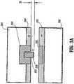
- Cutting element 295is configured to extend from insulator 290 and the tissue contacting surface 284 a distance "B" (See Fig. 3A ) such that the cutting element 295 acts as a gap stop (i.e., creates a gap distance "G" (See Fig. 4A ) between conductive sealing surfaces 284 and 286) which promotes accurate, consistent and effective tissue sealing.
- the cutting element 295also prevents the two tissue contacting surfaces 284 and 286 from touching which eliminates the chances of the instrument shorting during sealing.
- the cutting element 295extends from the tissue contacting surface 284 a predetermined distance "B" according to the specific material properties (e.g., compressive strength, thermal expansion, etc.) to yield a consistent and accurate gap distance "G" during sealing ( Fig. 4A ).
- the gap distance "G" during sealingranges from about 0.001 inches to about 0.006 inches (about 25 ⁇ m to about 150 ⁇ m) and, more preferably, between about 0.002 inches and about 0.003 inches (about 50 ⁇ m to about 75 ⁇ m).
- the clamping pressure between the opposing tissue contacting surfaces 284 and 286is preferably between about 3 kg/cm 2 to about 16 kg/cm 2 .
- the pressure between the cutting element 295 and the opposite insulator 292is much higher due to the smaller surface area of the cutting element 295 against the insulator 292.
- the conductive cutting element 295is oriented in opposing, vertical registration with the insulator 292 of jaw member 282. It is envisioned that the cutting element 295 is substantially dull which, as can be appreciated, does not inhibit the sealing process (i.e., premature cutting) during initial electrosurgical activation. In other words, the surgeon is free to manipulate, grasp and clamp the tissue 400 for sealing purposes without the cutting element 295 mechanically cutting into the tissue 400. Moreover, tissue cutting can only be achieved through a combination of mechanically clamping the tissue between the cutting element 295 and the opposing insulator 292 and applying electrosurgical energy from the cutting element 295, through the tissue 400 and to the return electrode, i.e., the electrically conductive tissue contacting surface 286.
- the geometrical configuration of the cutting element 295plays an important role in determining the overall effectiveness of tissue cut.
- the power/current concentration around the cutting element 295is based upon the particular geometrical configuration of the cutting element 295 and the cutting element's 295 proximity to the return electrode, i.e., tissue contacting surface 286.
- Certain geometries on the cutting elementcreate areas of high power/current concentration.
- the spacing of the return electrode 286 to these power/current concentrationseffects the electrical fields through the tissue 400. Therefore, by configuring the cutting element 295 and insulator 292 within close proximity to one another the electrical current field remains high which is ideal for cutting but the instrument will not short due to accidental contact between conductive surfaces.
- the relative size of the cutting element 295 and/or the size of the insulator 292may be selectively altered to accomplish this purpose.
- Figs. 3B and 3Cshows schematic examples of how the tissue contacting surfaces 284 and 286 and the cutting element 295 may be electrically coupled to an electrosurgical generator 340 (ESU) and switch controllers. More particularly, Fig. 3B shows an electrical lead 297 extending from tissue contacting surface 284 and an electrical lead 298 extending from tissue contacting surface 286. More particularly, lead 297 couples the tissue contacting surface 284 to a switch 350, lead 352 couples the switch 350 to a smart sensor 355 and lead 342 couples the smart sensor 355 to the ESU 340, respectively. Lead 298 couples the tissue contacting surface 286 directly to the ESU 340. With respect to the cutting element 295, lead 299 couples the cutting element 295 to switch 350, lead 354 couples the switch 350 to the smart sensor 355 and lead 342 couples the smart sensor 355 to the ESU 340, respectively.
- ESUelectrosurgical generator 340
- this electrical arrangementallows the surgeon to initially activate the two opposing tissue contacting surfaces 284 and 286 to seal the tissue 400 and, subsequently, selectively and independently activate the cutting element 295 and tissue contacting surface 286 to cut the tissue 400. Hence, the tissue 400 is initially sealed and thereafter cut without re-grasping the tissue.
- the cutting element 295 and the tissue contacting surface 286may also be activated to simply cut tissue/vessels without initially sealing.
- the jaw members 280 and 282may be opened and the cutting element 295 may be selectively activated to dissect or coagulate tissue 400.
- This type of alternative embodimentmay be particularly useful during certain endoscopic procedures wherein an electrosurgical pencil is typically introduced to coagulate and/or dissect tissue during the operating procedure.
- a switch 350may be employed to allow the surgeon to selectively activate tissue contacting surface 284 or the cutting element 295 independently of one another. As can be appreciated, this allows the surgeon to initially seal tissue 400 and then activate the cutting element 295 by simply turning the switch 350. Rocker switches, toggle switches, flip switches, dials, etc. are types of switches which can be commonly employed to accomplish this purpose. It is also envisioned that the switch 350 may cooperate with the smart sensor 355 (or smart circuit, computer, feedback loop, etc.) which automatically triggers the switch 350 to change between the "sealing" mode and the "cutting" mode upon the satisfaction of a particular parameter.
- the smart sensor 355may include a feedback loop which indicates when a tissue seal is complete based upon one or more of the following parameters: tissue temperature, tissue impedance at the seal 410, change in impedance of the tissue over time and/or changes in the power or current applied to the tissue over time.
- An audible or visual feedback monitor 360may be employed to convey information to the surgeon regarding the overall seal quality or the completion of an effective tissue seal 410.
- a separate lead 346may be connected between the smart sensor 355 and the ESU for visual and/or audible feedback purposes.
- the ESU 340delivers energy to the tissue in a pulse-like waveform. It has been determined that delivering the energy in pulses increases the amount of sealing energy which can be effectively delivered to the tissue and reduces unwanted tissue effects such as charring.
- the feedback loop of the smart sensor 355can be configured to automatically measure various tissue parameters during sealing (i.e., tissue temperature, tissue impedance, current through the tissue) and automatically adjust the energy intensity and number of pulses as needed to reduce various tissue effects such as charring and thermal spread.
- RF pulsingmay be used to more effectively cut tissue.
- an initial pulse from the cutting element 295 through the tissue 400may be delivered to provide feedback to the smart sensor 355 for selection of the ideal number of subsequent pulses and subsequent pulse intensity to effectively and consistently cut the amount or type of tissue 400 with minimal effect on the tissue seal 410.
- electrical cuttingoccurs in spikes which are generally within the first 0.01 seconds to 0.5 seconds of energy application. If the energy is not pulsed, the tissue may not initially cut but desiccate since tissue impedance remains high during the initial stages of cutting. By providing the energy in short, high energy pulses, it has been found that the tissue 400 is more likely to cut.
- switch 350may be configured to activate based upon a desired cutting parameter and/or after an effective seal is created or has been verified. For example, after effectively sealing the tissue 400, the cutting element 295 may be automatically activated based upon a desired end tissue thickness at the seal 410.
- Fig. 3Cshows another alternative embodiment of the present disclosure which utilizes two active switches 350a and 350b to separately and independently energize the conductive elements, i.e., tissue contacting surface 284 and cutting element 295. As such, the surgeon actively depresses switch 350a to effect sealing and switch 350b to effect cutting. Tissue contacting surface 286 is directly coupled to the ESU 340 and acts as the return electrode in either instance.
- FIG. 4Ashows the pathway of the electrosurgical energy 420 from the opposing conductive surfaces 284 and 286 and through the tissue 400 during the sealing process and Figs. 4B and 4C show the pathway of the electrosurgical energy 420 from the cutting element 295 and through the tissue 400 during the cutting process. More particularly, Fig. 4A shows the tissue 40 being compressed between the conductive tissue contacting surfaces 284 and 286 of the jaw member 280 and 282 under a closure pressure "F" in the range of about 3 kg/cm 2 to about 16 kg/cm 2 .
- Applying the correct force "F"is also important for other reasons: to oppose the walls of the vessel; to reduce the tissue impedance to a low enough value that allows enough current through the tissue 400; and to overcome the forces of expansion during tissue heating in addition to contributing towards creating the required end tissue thickness which is an indication of a good tissue seal 410.
- Tissue pressures within a working range of about 7 kg/cm 2 to about 13 kg/cm 2have been shown to be particularly effective for sealing arteries and vascular bundles.
- the cutting element 295Upon compression, the cutting element 295 acts as a stop member and creates a gap "G" between the opposing conductive tissue contacting surfaces 284 and 286.
- the gap distanceis in the range of (about 0.001 to about 0.006 inches) (about 25 ⁇ m to about 150 ⁇ m).
- controlling both the gap distance "G” and clamping pressure "F” between conductive surfaces 284 and 286are two important mechanical parameters which need to be properly controlled to assure a consistent and effective tissue seal.
- the surgeonactivates the ESU 340 and the switch 350 (either manually or automatically as described above) to transmit electrosurgical energy 420 to the tissue contacting surfaces 284 and 286 and through the tissue 400 to effect a seal 410.
- the tissue collagenmelts into a fused mass with limited demarcation between opposing vessel walls.
- the surgeonactivates the cutting element 295 as illustrated in Figs. 4B and 4C . More particularly, the surgeon activates the switch 350 to energize the cutting element 295 to cut the tissue 400. As mentioned above, the surgeon does not necessarily need to re-grasp the tissue 400 to cut, i.e., the cutting element 295 is already positioned proximate the ideal, center cutting line of the seal. As best seen in Fig. 4C , the highly concentrated electrosurgical energy 420 (see current field lines) travels from the tip of the cutting element 295 through the tissue 400 to cut the tissue 400 into two distinct halves 430a and 430b.
- the number of pulses required to effectively cut the tissue 400 and the intensity of the cutting energy 420may be determined by measuring the seal thickness and/or tissue impedance and/or based upon an initial calibrating energy pulse which measures similar parameters.
- a smart sensor 355See Fig. 3B ) or feedback loop may be employed for this purpose.
- the cutting element 295may include opposing corner edges 296 having substantially rounded corners.
- Other cutting element 295 geometriesare envisioned as well to create different power concentrations depending upon a particular purpose.
- Fig. 5Ashows one alternate example of an electrode assembly 500 wherein jaw member 582 includes a tissue contacting surface 584 having an insulator 590 extending along the longitudinal length thereof.
- the insulator 590extends a distance "E” toward the opposing tissue contacting surface 586 to create the stop gap "G" between opposing tissue contacting surfaces 584 and 586 during sealing.
- a cutting element 595is recessed within the insulator 590 a distance "R" such that the cutting element 595 does not touch the opposing tissue contacting surface 586 during the sealing and cutting processes.
- tissue contacting surface 586does not include an insulator oriented opposite the cutting element 595 thus simplifying the overall manufacturing process.
- the recessed cutting element 595is designed to create very high current densities due to the proximity of the insulator 590 relative to the edge 597 of the cutting element 595, i.e., high current densities are created at the insulator/electrode interface 599.
- this particular design of the electrode assembly 510places the cutting element 595 next to the high pressure insulator/electrode interface 599 (high-pressure clamping zone).
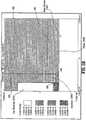
- a finite element modelshows a concentration of high current density near the insulator/electrode interface 599 as a result of placing the cutting element 595 in close proximity to the high-pressure clamping zone 598. It is envisioned that this particular configuration of the cutting element 595 allows for cutting with lower power requirements.
- a pulsing RF output from the ESU 340may be employed to more effectively cut the tissue 400 as described above.
- Figs. 6A and 6bshow an alternate embodiment of the present disclosure wherein the polarities of the sealing electrodes are changed after sealing to effect tissue cutting. More particularly, as best shown in Fig. 6A , a first pair of sealing electrodes 284a and 284b having a first polarity are disposed on jaw member 280 and a second pair of sealing electrodes 286a and 286b having a second polarity are disposed on jaw member 282.
- a plurality of electrical connections 293, 297, 298 and 299connect each electrode 286b, 284b, 286a and 284a, respectively, to the electrosurgical generator 340. Electrodes 284a and 286a and electrodes 284b and 286b are positioned in opposing relation relative to one another such that electrosurgical energy 420 can be effectively communicated through tissue 400 when held between the two jaw members 280 and 282.
- electrosurgical energyis transferred between opposing electrodes 284a and 286a and electrodes 284b and 286b and through the tissue 400 generally in the manner shown in Fig. 6A .
- electrosurgical energycontrolled gap distance between opposing electrodes 284a and 286a and electrodes 284b and 286b and controlled closing pressure will assure a consistent and effective tissue seal.
- the surgeoncan opt to cut or divide the tissue along the tissue seal.
- the instrumentmay be configured to automatically cut the tissue 400 once sealed or the instrument may be configured to permit the surgeon to selectively divide the tissue 400 once sealed.
- an audible or visual indicatormay be triggered by a sensor (not shown) to alert the surgeon when an effective seal has been created.
- the sensormay, for example, determine if a seal is complete by measuring one of tissue impedance, tissue opaqueness and/or tissue temperature.
- Commonly-owned U.S. Application Serial No. 10/427,832 published as US-A-2004 015163describes several electrical systems which may be employed to provide positive feedback to the surgeon to determine tissue parameters during and after sealing and to determine the overall effectiveness of the tissue seal.
- the electrical potential of two of the four electrodese.g., electrode 284b and electrode 286a
- an electrical or electromechanical switchmay be activated after the sealing stage to switch the electrical potential of two of the four electrodes. It is contemplated that the electrical potentials of the electrodes 284a, 284b, 286a and 286b may be reconfigured in any fashion to effect cutting depending upon a particular purpose.
- the electrical potentials of electrodes 286a and 284bhave been changed to encourage a substantially diagonal electrosurgical cutting path through the tissue 400. More particularly, as the tissue impedance rises, the electrosurgical energy will be directed diagonally towards the electrically opposing electrodes on the opposite jaw member. It is contemplated that the two electrical paths will cross and cut tissue generally along a center line "C".
- the electrosurgical intensity from each of the electrodes 284a, 284b, 286a and 286bis selectively or automatically controllable to assure consistent and accurate cutting along the centerline "C" in view of the inherent variations in tissue type and/or tissue thickness.
- the entire surgical processmay be automatically controlled such that after the tissue is initially grasped the surgeon may simply activate the forceps to seal and subsequently cut tissue.
- the generator 340may be configured to communicate with one or more sensors (not shown) to provide positive feedback to the generator 340 during both the sealing and cutting processes to insure accurate and consistent sealing and division of tissue 400.
- commonly-owned U.S. Patent Application Serial No. 10/427,832discloses a variety of feedback mechanisms which may be employed for this purpose.
- the present disclosureincludes description A a method for sealing and cutting tissue and includes the steps of: providing an electrode assembly, e.g., 210, having a pair of opposing first and second jaw members 280, 282 which are movable relative to one another from a first position wherein the jaw members 280, 282 are disposed in spaced relation relative to one another to a second position wherein the jaw members 280, 282 cooperate to grasp tissue 400 therebetween.
- Each of the jaw members 280, 282includes an electrically conductive tissue contacting surface 284, 286, respectively, which is connected to the ESU 340.
- An electrically conductive cutting element 295is dielectrically disposed within the first tissue contacting surface 284 and the cutting element 295 extends from the first tissue contacting surface 284 towards the second tissue contacting surface 286.
- the cutting element 295creates a gap "G" between the first and second tissue contacting surfaces 284, 286 between about 0.001 inches to about 0.006 inches (about 25 ⁇ m to about 150 ⁇ m).
- An insulatoris disposed within the second tissue contacting surface 286 in substantially opposing relation to the cutting element.
- the methodfurther includes the steps of: actuating the jaw members 280, 282 to grasp tissue 400 between tissue contacting surfaces 284, 286; applying a closure force "F" between tissue contacting surfaces 284, 286 between about 3 kg/cm 2 to about 16 kg/cm 2 such that the cutting element 295 creates a gap "G" between the first and second tissue contacting surfaces 284, 286; energizing the first and second tissue contacting surfaces 284, 286 to deliver electrosurgical energy 420 through the tissue 400 to effect a tissue seal 410; and energizing the cutting element 295 and the second tissue contacting surface 286 to deliver electrosurgical energy 420 through the tissue 400 to effectively cut the tissue 400 along the tissue seal 410.
- the methodmay include the step of: utilizing a smart sensor to determine seal quality prior to cutting tissue 400.
- tissue contacting surfaces 284 and 286may include radiused edges to facilitate sealing and reduce possible collateral damage to tissue during sealing.
- the forceps 10may include a second smart sensor or additional feedback mechanism (not shown) which automatically selects the appropriate amount of electrosurgical energy to effectively seal the particularly-sized tissue grasped between the jaw members 280 and 282.
- the outer surface of the jaw members 280 and 282may include a nickel-based material, coating, stamping and/or metal injection molding which is designed to reduce adhesion between the jaw members 280, 282 (or components thereof) with the surrounding tissue during activation, sealing and cutting.
- the tissue contacting surfaces 284 and 286may be manufactured from one (or a combination of one or more) of the following materials: nickel-chrome, chromium nitride, MedCoat 2000 manufactured by The Electrolizing Corporation of OHIO, inconel 600 and tin-nickel.
- the tissue contacting surfaces 284, 286 and/or the conductive cutting element 295may also be coated with one or more of the above materials to achieve the same result, i.e., a "non-stick surface".
- the non-stick materialsare of a class of materials that provide a smooth surface to prevent mechanical tooth adhesions.
- these materialsprovide an optimal surface energy for eliminating sticking due in part to surface texture and susceptibility to surface breakdown due electrical effects and corrosion in the presence of biologic tissues. It is envisioned that these materials exhibit superior non-stick qualities over stainless steel and should be utilized on the forceps 10, 200 in areas where the exposure to pressure and electrosurgical energy can create localized "hot spots" more susceptible to tissue adhesion. As can be appreciated, reducing the amount that the tissue "sticks" during sealing improves the overall efficacy of the instrument.
- the non-stick materialsmay be manufactured from one (or a combination of one or more) of the following “non-stick” materials: nickel-chrome, chromium nitride, MedCoat 2000, Inconel 600 and tin-nickel.
- nickel-chromenickel-chrome
- chromium nitrideMedCoat 2000, Inconel 600
- tin-nickelhigh nickel chrome alloys, Ni200, Ni201 ( ⁇ 100% Ni) may be made into the sealing surfaces 284, 286 or the cutting element 295 by metal injection molding, stamping, machining or any like process.
- the tissue sealing surfaces 284 and 286 and/or the conductive cutting element 295may also be "coated” with one or more of the above materials to achieve the same result, i.e., a "non-stick surface".
- Nitride coatings(or one or more of the other above-identified materials) may be deposited as a coating on another base material (metal or nonmetal) using a vapor de
- nitride coatingswhich include, but not are not limited to: TiN, ZrN, TiAlN, and CrN are preferred materials used for non-stick purposes. CrN has been found to be particularly useful for non-stick purposes due to its overall surface properties and optimal performance. Other classes of materials have also been found to reducing overall sticking. For example, high nickel/chrome alloys with a Ni/Cr ratio of approximately 5:1 have been found to significantly reduce sticking in bipolar instrumentation.
- One particularly useful non-stick material in this classis Inconel 600. Bipolar instrumentation having sealing surfaces 284 and 286 made from or coated with Ni200, Ni201 ( ⁇ 100% Ni) also showed improved non-stick performance over typical bipolar stainless steel electrodes.
- chromium nitridemay be applied using a physical vapor deposition (PVD) process that applies a thin uniform coating to the entire conductive surface.
- PVDphysical vapor deposition
- This coatingproduces several effects: 1) the coating fills in the microstructures on the metal surface that contribute to mechanical adhesion of tissue to surfaces; 2) the coating is very hard and is a non-reactive material which minimizes oxidation and corrosion; and 3) the coating tends to be more resistive than the base material causing conductive surface heating which further enhances desiccation and seal quality.
- the Inconel 600 coatingis a so-called "super alloy” which is manufactured by Special Metals, Inc. located in Conroe Texas.
- the alloyis primarily used in environments which require resistance to corrosion and heat.
- the high Nickel content of Inconelmakes the material especially resistant to organic corrosion. As can be appreciated, these properties are desirable for bipolar electrosurgical instruments which are naturally exposed to high temperatures, high RF energy and organic matter.
- the resistivity of Inconelis typically higher than the base conductive material which further enhances desiccation and seal quality.
- the present inventionrelates to the transfer of electrosurgical energy though opposing electrically conductive sealing surfaces having different electrical potentials to effect vessel sealing.
- the presently disclosed embodiments discussed hereinmay be designed to seal the tissue structure using so-called "resistive heating” whereby the tissue contacting surfaces 284 and 286 are not necessarily electrically conductive surfaces. Rather, each of the surfaces 284 and 286 is heated much like a conventional "hot plate” such that the surfaces 284 and 286 cooperate to seal the tissue upon contact (or upon activation of a switch (not shown) which selectively heats each surface 284 and 286 upon activation).
- the presently disclosed forceps 10, 200is designed to electrically couple to a foot switch (not shown) which allows the surgeon to selectively control the electrosurgical energy transferred to the tissue either to effect sealing and/or cutting.
- a handswitch(not shown) may also be utilized.
- the handswitchreduces the amount of electrical cable in the operating room and virtually eliminates the possibility of activating the wrong instrument or feature during a surgical procedure due to "line-of-sight" activation.
- cutting element 295may be dimensioned as a cutting wire which is selectively activatable by the surgeon to divide the tissue 400 after sealing. More particularly, a wire is mounted within the insulator 290 between the jaw members 280 and 282 and is selectively energizable upon activation of the switch 350.
- the electrode assembly 110, 210could be selectively detachable (i.e., reposable) from the shaft 12, 212, respectively, depending upon a particular purpose.
- the entire instrumentcould be disposable.
- specific forceps 10, 200could be configured for different tissue types or thicknesses.
- a reusable forceps 10, 200could be sold as a kit having different electrodes assemblies 110, 210 for different tissue types. The surgeon simply selects the appropriate electrode assembly for a particular tissue type.
- variable resistorcould be employed to regulate the electrosurgical energy to effect sealing and or cutting a particular tissue type.
- the variable resistorcould be coupled to a sensor which determines tissue type, tissue impedance, tissue moisture, tissue thickness, etc. and regulates the appropriate electrosurgical energy intensity by automatically adjusting the variable resistor to seal and /or the cut tissue.
- Figs. 1-4Cshow the cutting element 295 as extending from the insulator 290 toward the second tissue contacting surface 286, it is envisioned that other jaw arrangements are plausible which would accomplish the same or similar purposes.
- the cutting element 295could be relatively flush within the insulator 290 and the bottom insulating surface 292 could extend beyond the tissue contacting surface 286 towards the opposing first tissue contacting surface 284.
- both the cutting element and the insulating surface 292are flush and a gap stop is created elsewhere on the tissue contacting surfaces or elsewhere in the instrument.
- Various embodiments of stop member configurations and stop gap actuatorsare disclosed in commonly-owned PCT Patent Application Serial Nos. PCT US 02/01890 and PCT/US01/11413 .
Landscapes
- Health & Medical Sciences (AREA)
- Surgery (AREA)
- Engineering & Computer Science (AREA)
- Life Sciences & Earth Sciences (AREA)
- Biomedical Technology (AREA)
- Otolaryngology (AREA)
- Nuclear Medicine, Radiotherapy & Molecular Imaging (AREA)
- Plasma & Fusion (AREA)
- Physics & Mathematics (AREA)
- Heart & Thoracic Surgery (AREA)
- Medical Informatics (AREA)
- Molecular Biology (AREA)
- Animal Behavior & Ethology (AREA)
- General Health & Medical Sciences (AREA)
- Public Health (AREA)
- Veterinary Medicine (AREA)
- Surgical Instruments (AREA)
Description
- The present disclosure relates to an electrode assembly for use with electrosurgical instruments and, more particularly, the present disclosure relates to an electrode assembly for use with an open or endoscopic electrosurgical forceps for sealing and cutting tissue. The two part form
A claim 1 below is based onUS-B1-6174309 . - Open or endoscopic electrosurgical forceps utilize both mechanical clamping action and electrical energy to effect hemostasis. The electrode of each opposing jaw members is charged to a different electric potential such that when the jaw members grasp tissue, electrical energy can be selectively transferred through the tissue. A surgeon can either cauterize, coagulate/desiccate and/or simply reduce or slow bleeding, by controlling the intensity, frequency and duration of the electrosurgical energy applied between the electrodes and through the tissue.
- To effectively seal tissue or vessels, especially thick tissue and large vessels, two predominant mechanical parameters must be accurately controlled: 1) the pressure applied to the vessel; and 2) the gap distance between the conductive tissue contacting surfaces (electrodes). As can be appreciated, both of these parameters are affected by the thickness of the vessel being sealed. Accurate application of pressure is important for several reasons: to oppose the walls of the vessel; to reduce the tissue impedance to a low enough value that allows enough electrosurgical energy through the tissue; to overcome the forces of expansion during tissue heating; and to contribute to the end tissue thickness which is an indication of a good seal. It has been determined that a typical fused vessel wall is optimum between 0.001 and 0.006 inches (about 25 to 155 µm). Below this range, the seal may shred or tear and above this range the lumens may not be properly or effectively sealed.
- With respect to smaller vessels, the pressure applied becomes less relevant and the gap distance between the electrically conductive surfaces becomes more significant for effective sealing. In other words, the chances of the two electrically conductive surfaces touching during activation increases as the tissue thickness and the vessels become smaller. However, the process of "coagulating" small vessels is fundamentally different than electrosurgically "sealing" vessels. For the purposes herein, "coagulation" is defined as a process of desiccating tissue wherein the tissue cells are ruptured and dried. "Vessel sealing" is defined as the process of liquefying the collagen in the tissue so that it reforms into a fused mass with significantly-reduced demarcation between the opposing tissue structures (opposing walls of the lumen). Coagulation of small vessels is usually sufficient to permanently close them. Larger vessels need to be sealed to assure permanent closure.
U.S. Patent No. 2,176,479 to Willis ,U.S. Patent Nos. 4,005,714 and4,031,898 to Hiltebrandt ,U.S. Patent Nos. 5,827,274 ,5,290,287 and5,312,433 to Boebel et al. ,U.S. Patent Nos. 4,370,980 ,4,552,143 ,5,026,370 and5,116,332 to Lottick ,U.S. Patent No. 5,443,463 to Stern et al. ,U.S. Patent No. 5,484,436 to Eggers et al. andU.S. Patent No. 5,951,549 to Richardson et al. , all relate to electrosurgical instruments for coagulating and cutting vessels or tissue. So far as is known, none of these designs provide uniformly reproducible pressure to the vessel or control the gap distance between electrically conductive surfaces and, thus, do not result in a uniform, consistent or effective seal.- Many of these instruments include blade members or shearing members which simply cut tissue in a mechanical and/or electromechanical manner and are relatively ineffective for vessel sealing purposes. Other instruments rely on clamping pressure alone to procure proper sealing thickness and are not designed to take into account gap tolerances and/or parallelism and flatness requirements which are parameters which, if properly controlled, can assure a consistent and effective tissue seal. For example, it is known that it is difficult to adequately control thickness of the resulting sealed tissue by controlling clamping pressure alone for either of two reasons: 1) if too much force is applied, there is a possibility that the two poles will touch and energy will not be transferred through the tissue resulting in an ineffective seal; or 2) if too low a force is applied the tissue may pre-maturely move prior to activation and sealing and/or a thicker, less reliable seal may be created.
- Typically and particularly with respect to endoscopic electrosurgical procedures, once a vessel is sealed, the surgeon has to remove the sealing instrument from the operative site, substitute a new instrument through the cannula and accurately sever the vessel along the newly formed tissue seal. As can be appreciated, this additional step may be both time consuming (particularly when sealing a significant number of vessels) and may contribute to imprecise separation of the tissue along the sealing line due to the misalignment or misplacement of the severing instrument along the center of the tissue seal.
- Several attempts have been made to design an instrument which incorporates a knife or blade member which effectively severs the tissue after forming a tissue seal. For example,
U.S. Patent No. 5,674,220 to Fox et al. discloses a transparent instrument which includes a longitudinally reciprocating knife which severs the tissue once sealed. The instrument includes a plurality of openings which enable direct visualization of the tissue during the treatment and severing processes. This direct visualization allows a user to visually and manually regulate the closure force and gap distance between jaw members to reduce and/or limit certain undesirable visual effects known to occur when treating vessels, thermal spread, charring, etc. As can be appreciated, the overall success of creating an effective tissue seal with this instrument is greatly reliant upon the user's expertise, vision, dexterity, and experience in judging the appropriate closure force, gap distance and length of reciprocation of the knife to uniformly, consistently and effectively seal the vessel and separate the tissue at the seal along an ideal cutting plane. U.S. Patent No. 5,702,390 to Austin et al. discloses an instrument which includes a triangularly-shaped electrode which is rotatable from a first position to treat tissue to a second position to cut tissue. Again, the user must rely on direct visualization and expertise to control the various effects of treating and cutting tissue.- Thus, a need exists to develop an electrosurgical instrument which includes an electrode assembly which enables the surgeon to both seal the tissue in an effective and consistent manner and subsequently separate the tissue along the tissue seal without re-grasping the tissue or removing the instrument from the operating cavity.
- The invention in defined in
claim 1 below. The dependent claims are directed to optional features and preferred embodiments. - The present disclosure relates to an electrode assembly for use with an instrument for sealing vessels. The electrode assembly includes a pair of opposing first and second jaw members which are movable relative to one another from a first position wherein the jaw members are disposed in spaced relation relative to one another to a second position wherein the jaw members cooperate to grasp tissue therebetween. Each jaw member includes an electrically conductive tissue contacting surface which is connected to an electrosurgical generator (ESU) such that the tissue contacting surfaces are capable of conducting electrosurgical energy through the tissue held therebetween to effect a tissue seal.
- The first jaw member includes an electrically conductive cutting element dielectrically disposed within the first tissue contacting surface and the second jaw member includes an insulator disposed therein opposite the cutting element. The cutting element extends outwardly from the first tissue contacting surface towards the second tissue contacting surface to create a gap between the tissue contacting surfaces during sealing. One advantage of the present invention is that the cutting element and the first tissue contacting surface are independently activatable by the surgeon to selectively "cut" or "seal" the tissue, respectively. Another advantage of the present invention is that the cutting element is substantially dull and only capable of cutting tissue through electrosurgical activation.
- The electrode assembly includes a smart sensor for determining overall seal quality prior to activating the cutting element. The smart sensor may employ an audible or visual indicator depending upon a particular purpose to provide feedback to the surgeon regarding overall seal quality. It may be advantageous to have the smart sensor determine seal quality by measuring the drop in current across the tissue, by measuring the tissue impedance across the tissue and/or by measuring the tissue temperature or moisture content of the tissue.
- The same or a second smart sensor is employed to measure or determine various tissue parameters to regulate / control the electrosurgical energy supplied to the cutting element during cutting. Preferably, after a tissue seal is created, the smart sensor measures at least one of tissue thickness, tissue moisture, tissue density and/or tissue impedance to regulate / control the electrosurgical energy supplied to the cutting element during cutting. Advantageously, the ESU can be designed to send a calibrating pulse through the tissue which enables the smart sensor to measures various tissue parameters to control the electrosurgical energy supplied to the cutting element during cutting.
- Yet, in another advantageous embodiment according to the present disclosure, a smart sensor is employed to automatically switch electrosurgical energy to the cutting element once the tissue is sealed. In still yet another particularly useful embodiment, the ESU is configured to deliver electrosurgical energy in a pulse-like manner to effect at least one of cutting and sealing. Another advantageous embodiment employs a smart sensor which includes a variable resistor which automatically regulates the electrosurgical energy from the ESU during both the sealing and cutting processes.
- The present disclosure includes description of a method for sealing and cutting tissue and includes the steps of: providing an electrode assembly having a pair of opposing first and second jaw members which are movable relative to one another from a first position wherein the jaw members are disposed in spaced relation relative to one another to a second position wherein the jaw members cooperate to grasp tissue therebetween. Preferably, each of the electrically conductive tissue contacting surfaces is connected to the ESU.
- An electrically conductive cutting element is dielectrically disposed within the first tissue contacting surface. The cutting element extends from the first tissue contacting surface towards the second tissue contacting surface. Preferably, when the tissue contacting surfaces are closed about the tissue, the cutting element creates a gap "G" between the first and second tissue contacting surfaces. An insulator is disposed within the second tissue contacting surface opposite the cutting element.
- The method further includes the steps of: actuating the jaw members to grasp tissue between tissue contacting surfaces; applying a closure force "F" between tissue contacting surfaces such that the cutting element creates a gap "G" between the first and second tissue contacting surfaces; energizing the first and second tissue contacting surfaces to deliver electrosurgical energy through the tissue to effect a tissue seal; and energizing the cutting element and the second tissue contacting surface to deliver electrosurgical energy through the tissue to effectively cut the tissue along the tissue seal.
- After the step of energizing the first and second tissue contacting surfaces to effect a tissue seal, the method includes the step of: utilizing a smart sensor to determine seal quality prior to cutting the tissue.
- Various embodiments of the subject instrument are described herein with reference to the drawings wherein:
Fig. 1A is a left, perspective view of an endoscopic bipolar forceps showing a housing, a shaft and an electrode assembly according to the present disclosure;Fig. 1B is a left, perspective view of an open bipolar forceps having an electrode assembly according to the present disclosure;Fig. 2 is an enlarged view of a selectively detachable electrode assembly according to the present disclosure;Fig. 3A is a schematic, front view showing a first jaw member having a tissue contacting surface with a cutting element disposed therein and a second jaw member having a tissue contacting surface with an insulator disposed therein opposite the cutting element;Fig. 3B is a schematic, front view showing the tissue contacting surfaces and their respective electrical connections to a switch controller, a smart sensor and/or an electrosurgical generator;Fig. 3C is a schematic, front view showing alternate electrical connections to the switch controller and the electrosurgical generator;Fig. 4A is a schematic, front view showing tissue being sealed between tissue contacting surfaces through a combination of clamping the tissue in a particular pressure range, maintaining a desired gap range between opposing tissue contacting surfaces during sealing and applying a predetermined amount of electrosurgical energy through the tissue;Fig. 4B is a schematic, front view showing tissue being cut by the cutting element through a combination of applying a cutting pressure within a particular range and applying electrosurgical energy from the cutting element through the tissue;Fig. 4C is an enlarged, schematic view ofFig. 4B showing the path of the electrosurgical current from the cutting element, through the tissue and to the second tissue contacting surface;Fig. 5A is a schematic, front view of an alternate jaw configuration for the electrode assembly;Fig. 5B is a finite element analysis model of showing the current
density during cutting utilizing the alternate jaw member configuration ofFig. 5A ; andFigs. 6A and 6B are schematic views of an alternate embodiment of instrument wherein the polarities of the electrodes are changed to effect tissue cutting.- Referring now to
Figs. 1A and 1 B , a bipolar forceps 10 is shown for use with various surgical procedures. Forceps 10 generally includes ahousing 20, ahandle assembly 30, a rotatingassembly 80, atrigger assembly 70 and anelectrode assembly 110 which mutually cooperate to grasp, seal and divide tubular vessels and vascular tissue 400 (SeeFig. 4A ). Although the majority of the figure drawings depict a bipolar forceps 10 for use in connection with endoscopic surgical procedures, anopen forceps 200 is also contemplated for use in connection with traditional open surgical procedures and is shown by way of example inFig. 1B and is described below. For the purposes herein, either an endoscopic instrument or an open instrument may be utilized with the electrode assembly described herein. Obviously, different electrical and mechanical connections and considerations apply to each particular type of instrument, however, the novel aspects with respect to the electrode assembly and its operating characteristics remain generally consistent with respect to both the open or endoscopic designs. - More particularly, forceps 10 includes a
shaft 12 which has adistal end 14 dimensioned to mechanically engage theelectrode assembly 110 and a proximal end 16 which mechanically engages thehousing 20. Theshaft 12 may be bifurcated at thedistal end 14 thereof to receive theelectrode assembly 110. The proximal end 16 ofshaft 12 mechanically engages the rotatingassembly 80 to facilitate rotation of theelectrode assembly 110. In the drawings and in the descriptions which follow, the term "proximal", as is traditional, will refer to the end of the forceps 10 which is closer to the user, while the term "distal" will refer to the end which is further from the user. - As best seen in
Fig. 1A , forceps 10 also includes an electrical interface or plug 300 which connects the forceps 10 to a source of electrosurgical energy, e.g., an electrosurgical generator 340 (SeeFig. 3B ).Plug 300 includes a pair ofprong members 302a and 302b which are dimensioned to mechanically and electrically connect the forceps 10 to theelectrosurgical generator 340. Anelectrical cable 310 extends from theplug 300 to asleeve 99 which securely connects thecable 310 to the forceps 10.Cable 310 is internally divided within thehousing 20 to transmit electrosurgical energy through various electrical feed paths to theelectrode assembly 110. - Handle
assembly 30 includes a fixedhandle 50 and amovable handle 40. Fixedhandle 50 is integrally associated withhousing 20 and handle 40 is movable relative to fixedhandle 50 to actuate a pair of opposingjaw members electrode assembly 110 as explained in more detail below.Movable handle 40 and triggerassembly 70 are preferably of unitary construction and are operatively connected to thehousing 20 and the fixedhandle 50 during the assembly process. - As mentioned above,
electrode assembly 110 is attached to thedistal end 14 ofshaft 12 and includes a pair of opposingjaw members Movable handle 40 ofhandle assembly 30 imparts movement of thejaw members jaw members jaw members tissue 400 therebetween (SeeFig. 4A ). - It is envisioned that the forceps 10 may be designed such that it is fully or partially disposable depending upon a particular purpose or to achieve a particular result. For example,
electrode assembly 110 may be selectively and releasably engageable with thedistal end 14 of theshaft 12 and/or the proximal end 16 ofshaft 12 may be selectively and releasably engageable with thehousing 20 and thehandle assembly 30. In either of these two instances, the forceps 10 would be considered "partially disposable" or "reposable", i.e., a new or different electrode assembly 110 (orelectrode assembly 110 and shaft 12) selectively replaces theold electrode assembly 110 as needed. - Referring now to
Figs. 1B , anopen forceps 200 includes a pair ofelongated shaft portions 212a each having aproximal end distal end forceps 200 includeselectrode assembly 210 which attaches todistal ends shafts 212a and 212b, respectively.Electrode assembly 210 includes opposingjaw members pivot pin 219. - Preferably, each
shaft 212a and 212b includes ahandle 217a and 217b disposed at theproximal end finger hole 218a and 218b, respectively, therethrough for receiving a finger of the user. As can be appreciated,finger holes 218a and 218b facilitate movement of theshafts 212a and 212b relative to one another which, in turn, pivot thejaw members jaw members jaw members tissue 400 therebetween. Aratchet 230 is preferably included for selectively locking thejaw members - Preferably, each position associated with the cooperating ratchet interfaces 230 holds a specific, i.e., constant, strain energy in the
shaft members 212a and 212b which, in turn, transmits a specific closing force to thejaw members ratchet 230 may include graduations or other visual markings which enable the user to easily and quickly ascertain and control the amount of closure force desired between thejaw members - One of the shafts, e.g., 212b, includes a proximal shaft connector /
flange 221 which is designed to connect theforceps 200 to a source of electrosurgical energy such as anelectrosurgical generator 342. More particularly,flange 221 mechanically secureselectrosurgical cable 310 to theforceps 200 such that the user may selectively apply electrosurgical energy as needed. The proximal end of thecable 310 includes asimilar plug 300 as described above with respect toFig. 1A . The interior ofcable 310 houses a pair of leads which conduct different electrical potentials from theelectrosurgical generator 340 to thejaw members Fig. 2 . - Preferably, the
jaw members pivot 219 to effect the grasping and sealing oftissue 400. Eachjaw member tissue contacting surface tissue 400 during sealing and cutting. One of the jaw members includes acutting element 295 disposed therein which is explained in detail below. - As best shown in
Fig. 2 , the various electrical connections of theelectrode assembly 210 are preferably configured to provide electrical continuity to thetissue contacting surfaces cutting element 295 through theelectrode assembly 210. More particularly, twoconnector pins electrode assembly 210.Connections shafts 212a and 212b, respectively. As can be appreciated, theelectrical connectors shafts 212a and 212b during the assembly process of a disposable instrument or, alternatively, selectively removable for use with a reposable instrument. Connector 307 is internally connected to lead 298 disposed within theelectrode assembly 210 to provide electrical continuity totissue contacting surface 286 ofjaw member 282. Likewise,connector 308 is internally connected to lead 297 which provides electrical continuity totissue contacting surface 284 ofjaw member 280.Connector 308 also includes a secondelectrical interface 309 which provides electrical continuity to thecutting element 295 throughelectrode assembly 210.Interfaces tissue contacting surface 284 or thecutting element 295. Alternatively, theelectrode assembly 210 may include a single connector, e.g., 308, which includes an internal switch to allow selective and independent activation of thetissue contacting surface 284 and the cutting element 195. Preferably, theleads jaw members tissue 400. Likewise, the movement of thejaw members - As best seen in
Figs. 2 and3A- 3B jaw members tissue contacting surfaces respective jaw member 280 and 284). It is envisioned thattissue contacting surfaces jaw member jaw member tissue contacting surfaces - Preferably, the electrically conductive sealing surfaces 284 and 286 may also include a pinch trim (not shown) which facilitates secure engagement of the electrically
conductive surfaces jaw members conductive sealing surface respective jaw member conductive sealing surface - The electrically conductive
tissue contacting surfaces jaw members insulative material insulator tissue contacting surface tissue contacting surface insulators - Preferably, one or both of the
insulators insulators Jaw member 280 includes an electricallyconductive cutting element 295 disposed substantially within the insulator 190. As described in detail below, the cuttingelement 295 plays a dual role during the sealing and cutting processes. Preferably, theentire cutting element 295 is electrically conductive, however, it is envisioned that the cuttingelement 295 may be made from an insulative material with a conductive coating disposed thereon. Cuttingelement 295 is configured to extend frominsulator 290 and thetissue contacting surface 284 a distance "B" (SeeFig. 3A ) such that the cuttingelement 295 acts as a gap stop (i.e., creates a gap distance "G" (SeeFig. 4A ) between conductive sealing surfaces 284 and 286) which promotes accurate, consistent and effective tissue sealing. As can be appreciated, the cuttingelement 295 also prevents the twotissue contacting surfaces - As mentioned above, two mechanical factors play an important role in determining the resulting thickness of the sealed tissue and effectiveness of a
tissue seal 410, i.e., the pressure applied between opposingjaw members tissue contacting surfaces element 295 extends from thetissue contacting surface 284 a predetermined distance "B" according to the specific material properties (e.g., compressive strength, thermal expansion, etc.) to yield a consistent and accurate gap distance "G" during sealing (Fig. 4A ). Preferably, the gap distance "G" during sealing ranges from about 0.001 inches to about 0.006 inches (about 25 µm to about 150 µm) and, more preferably, between about 0.002 inches and about 0.003 inches (about 50 µm to about 75 µm). The clamping pressure between the opposingtissue contacting surfaces element 295 and theopposite insulator 292 is much higher due to the smaller surface area of the cuttingelement 295 against theinsulator 292. - As best seen in
Fig. 3A , theconductive cutting element 295 is oriented in opposing, vertical registration with theinsulator 292 ofjaw member 282. It is envisioned that the cuttingelement 295 is substantially dull which, as can be appreciated, does not inhibit the sealing process (i.e., premature cutting) during initial electrosurgical activation. In other words, the surgeon is free to manipulate, grasp and clamp thetissue 400 for sealing purposes without the cuttingelement 295 mechanically cutting into thetissue 400. Moreover, tissue cutting can only be achieved through a combination of mechanically clamping the tissue between the cuttingelement 295 and the opposinginsulator 292 and applying electrosurgical energy from the cuttingelement 295, through thetissue 400 and to the return electrode, i.e., the electrically conductivetissue contacting surface 286. - It is envisioned that the geometrical configuration of the cutting
element 295 plays an important role in determining the overall effectiveness of tissue cut. For example, the power/current concentration around the cuttingelement 295 is based upon the particular geometrical configuration of the cuttingelement 295 and the cutting element's 295 proximity to the return electrode, i.e.,tissue contacting surface 286. Certain geometries on the cutting element create areas of high power/current concentration. Moreover, the spacing of thereturn electrode 286 to these power/current concentrations effects the electrical fields through thetissue 400. Therefore, by configuring the cuttingelement 295 andinsulator 292 within close proximity to one another the electrical current field remains high which is ideal for cutting but the instrument will not short due to accidental contact between conductive surfaces. As can be appreciated, the relative size of the cuttingelement 295 and/or the size of theinsulator 292 may be selectively altered to accomplish this purpose. Figs. 3B and3C shows schematic examples of how thetissue contacting surfaces cutting element 295 may be electrically coupled to an electrosurgical generator 340 (ESU) and switch controllers. More particularly,Fig. 3B shows anelectrical lead 297 extending fromtissue contacting surface 284 and anelectrical lead 298 extending fromtissue contacting surface 286. More particularly, lead 297 couples thetissue contacting surface 284 to aswitch 350, lead 352 couples theswitch 350 to asmart sensor 355 and lead 342 couples thesmart sensor 355 to theESU 340, respectively. Lead 298 couples thetissue contacting surface 286 directly to theESU 340. With respect to thecutting element 295, lead 299 couples the cuttingelement 295 to switch 350, lead 354 couples theswitch 350 to thesmart sensor 355 and lead 342 couples thesmart sensor 355 to theESU 340, respectively.- As can be appreciated, this electrical arrangement allows the surgeon to initially activate the two opposing
tissue contacting surfaces tissue 400 and, subsequently, selectively and independently activate thecutting element 295 andtissue contacting surface 286 to cut thetissue 400. Hence, thetissue 400 is initially sealed and thereafter cut without re-grasping the tissue. - However, it is envisioned that the cutting
element 295 and thetissue contacting surface 286 may also be activated to simply cut tissue/vessels without initially sealing. For example, thejaw members cutting element 295 may be selectively activated to dissect or coagulatetissue 400. This type of alternative embodiment may be particularly useful during certain endoscopic procedures wherein an electrosurgical pencil is typically introduced to coagulate and/or dissect tissue during the operating procedure. - A
switch 350 may be employed to allow the surgeon to selectively activatetissue contacting surface 284 or thecutting element 295 independently of one another. As can be appreciated, this allows the surgeon to initially sealtissue 400 and then activate thecutting element 295 by simply turning theswitch 350. Rocker switches, toggle switches, flip switches, dials, etc. are types of switches which can be commonly employed to accomplish this purpose. It is also envisioned that theswitch 350 may cooperate with the smart sensor 355 (or smart circuit, computer, feedback loop, etc.) which automatically triggers theswitch 350 to change between the "sealing" mode and the "cutting" mode upon the satisfaction of a particular parameter. For example, thesmart sensor 355 may include a feedback loop which indicates when a tissue seal is complete based upon one or more of the following parameters: tissue temperature, tissue impedance at theseal 410, change in impedance of the tissue over time and/or changes in the power or current applied to the tissue over time. An audible or visual feedback monitor 360 may be employed to convey information to the surgeon regarding the overall seal quality or the completion of aneffective tissue seal 410. Aseparate lead 346 may be connected between thesmart sensor 355 and the ESU for visual and/or audible feedback purposes. - Preferably, the
ESU 340 delivers energy to the tissue in a pulse-like waveform. It has been determined that delivering the energy in pulses increases the amount of sealing energy which can be effectively delivered to the tissue and reduces unwanted tissue effects such as charring. Moreover, the feedback loop of thesmart sensor 355 can be configured to automatically measure various tissue parameters during sealing (i.e., tissue temperature, tissue impedance, current through the tissue) and automatically adjust the energy intensity and number of pulses as needed to reduce various tissue effects such as charring and thermal spread. - It has also been determined that RF pulsing may be used to more effectively cut tissue. For example, an initial pulse from the cutting
element 295 through the tissue 400 (or thetissue contacting surfaces smart sensor 355 for selection of the ideal number of subsequent pulses and subsequent pulse intensity to effectively and consistently cut the amount or type oftissue 400 with minimal effect on thetissue seal 410. It is believed that electrical cutting occurs in spikes which are generally within the first 0.01 seconds to 0.5 seconds of energy application. If the energy is not pulsed, the tissue may not initially cut but desiccate since tissue impedance remains high during the initial stages of cutting. By providing the energy in short, high energy pulses, it has been found that thetissue 400 is more likely to cut. - Alternatively, switch 350 may be configured to activate based upon a desired cutting parameter and/or after an effective seal is created or has been verified. For example, after effectively sealing the
tissue 400, the cuttingelement 295 may be automatically activated based upon a desired end tissue thickness at theseal 410. Fig. 3C shows another alternative embodiment of the present disclosure which utilizes twoactive switches tissue contacting surface 284 and cuttingelement 295. As such, the surgeon actively depressesswitch 350a to effect sealing and switch 350b to effect cutting.Tissue contacting surface 286 is directly coupled to theESU 340 and acts as the return electrode in either instance.- Turning now to the operation of the electrosurgical instrument 10 (or 200),
Fig. 4A shows the pathway of theelectrosurgical energy 420 from the opposingconductive surfaces tissue 400 during the sealing process andFigs. 4B and4C show the pathway of theelectrosurgical energy 420 from the cuttingelement 295 and through thetissue 400 during the cutting process. More particularly,Fig. 4A shows thetissue 40 being compressed between the conductivetissue contacting surfaces jaw member tissue 400; and to overcome the forces of expansion during tissue heating in addition to contributing towards creating the required end tissue thickness which is an indication of agood tissue seal 410. Tissue pressures within a working range of about 7 kg/cm2 to about 13 kg/cm2 have been shown to be particularly effective for sealing arteries and vascular bundles. - Upon compression, the cutting
element 295 acts as a stop member and creates a gap "G" between the opposing conductivetissue contacting surfaces conductive surfaces ESU 340 and the switch 350 (either manually or automatically as described above) to transmitelectrosurgical energy 420 to thetissue contacting surfaces tissue 400 to effect aseal 410. As a result of the unique combination of the clamping pressure "F", gap distance "G" andelectrosurgical energy 420, the tissue collagen melts into a fused mass with limited demarcation between opposing vessel walls. - Once sealed, the surgeon activates the cutting
element 295 as illustrated inFigs. 4B and4C . More particularly, the surgeon activates theswitch 350 to energize thecutting element 295 to cut thetissue 400. As mentioned above, the surgeon does not necessarily need to re-grasp thetissue 400 to cut, i.e., the cuttingelement 295 is already positioned proximate the ideal, center cutting line of the seal. As best seen inFig. 4C , the highly concentrated electrosurgical energy 420 (see current field lines) travels from the tip of the cuttingelement 295 through thetissue 400 to cut thetissue 400 into twodistinct halves 430a and 430b. As mentioned above, the number of pulses required to effectively cut thetissue 400 and the intensity of the cuttingenergy 420 may be determined by measuring the seal thickness and/or tissue impedance and/or based upon an initial calibrating energy pulse which measures similar parameters. A smart sensor 355 (SeeFig. 3B ) or feedback loop may be employed for this purpose. - As best seen in
Fig. 4C , the cuttingelement 295 may include opposing corner edges 296 having substantially rounded corners. Other cuttingelement 295 geometries are envisioned as well to create different power concentrations depending upon a particular purpose. - For example,
Fig. 5A shows one alternate example of an electrode assembly 500 whereinjaw member 582 includes atissue contacting surface 584 having aninsulator 590 extending along the longitudinal length thereof. In this embodiment, theinsulator 590 extends a distance "E" toward the opposingtissue contacting surface 586 to create the stop gap "G" between opposingtissue contacting surfaces element 595 is recessed within the insulator 590 a distance "R" such that the cuttingelement 595 does not touch the opposingtissue contacting surface 586 during the sealing and cutting processes. As can be appreciated,tissue contacting surface 586 does not include an insulator oriented opposite the cuttingelement 595 thus simplifying the overall manufacturing process. - In this embodiment, the recessed
cutting element 595 is designed to create very high current densities due to the proximity of theinsulator 590 relative to theedge 597 of the cuttingelement 595, i.e., high current densities are created at the insulator/electrode interface 599. As can be appreciated, this particular design of theelectrode assembly 510 places the cuttingelement 595 next to the high pressure insulator/electrode interface 599 (high-pressure clamping zone). As best illustrated inFig. 5B , a finite element model shows a concentration of high current density near the insulator/electrode interface 599 as a result of placing the cuttingelement 595 in close proximity to the high-pressure clamping zone 598. It is envisioned that this particular configuration of the cuttingelement 595 allows for cutting with lower power requirements. Preferably, a pulsing RF output from theESU 340 may be employed to more effectively cut thetissue 400 as described above. Figs. 6A and 6b show an alternate embodiment of the present disclosure wherein the polarities of the sealing electrodes are changed after sealing to effect tissue cutting. More particularly, as best shown inFig. 6A , a first pair of sealingelectrodes jaw member 280 and a second pair of sealingelectrodes 286a and 286b having a second polarity are disposed onjaw member 282. A plurality ofelectrical connections electrode electrosurgical generator 340.Electrodes electrodes 284b and 286b are positioned in opposing relation relative to one another such thatelectrosurgical energy 420 can be effectively communicated throughtissue 400 when held between the twojaw members - Upon initial activation and after the
tissue 400 is grasped betweenjaw members electrodes electrodes 284b and 286b and through thetissue 400 generally in the manner shown inFig. 6A . As mentioned above, the combination of electrosurgical energy, controlled gap distance between opposingelectrodes electrodes 284b and 286b and controlled closing pressure will assure a consistent and effective tissue seal. - Once the tissue is effectively sealed between opposing jaw members, the surgeon can opt to cut or divide the tissue along the tissue seal. As can be appreciated, the instrument may be configured to automatically cut the
tissue 400 once sealed or the instrument may be configured to permit the surgeon to selectively divide thetissue 400 once sealed. Moreover, it is envisioned that an audible or visual indicator (not shown) may be triggered by a sensor (not shown) to alert the surgeon when an effective seal has been created. The sensor may, for example, determine if a seal is complete by measuring one of tissue impedance, tissue opaqueness and/or tissue temperature. Commonly-ownedU.S. Application Serial No. 10/427,832 published asUS-A-2004 015163 , describes several electrical systems which may be employed to provide positive feedback to the surgeon to determine tissue parameters during and after sealing and to determine the overall effectiveness of the tissue seal. - As best seen in
Fig. 6B , during the cutting stage the electrical potential of two of the four electrodes, e.g.,electrode 284b andelectrode 286a, is changed which, as can be appreciated, alters the path of the electrosurgical energy through thetissue 400 when activated. More particularly, an electrical or electromechanical switch (not shown) may be activated after the sealing stage to switch the electrical potential of two of the four electrodes. It is contemplated that the electrical potentials of theelectrodes - For example and as shown in
Fig. 6B , the electrical potentials ofelectrodes tissue 400. More particularly, as the tissue impedance rises, the electrosurgical energy will be directed diagonally towards the electrically opposing electrodes on the opposite jaw member. It is contemplated that the two electrical paths will cross and cut tissue generally along a center line "C". - Preferably, the electrosurgical intensity from each of the
electrodes generator 340 may be configured to communicate with one or more sensors (not shown) to provide positive feedback to thegenerator 340 during both the sealing and cutting processes to insure accurate and consistent sealing and division oftissue 400. As mentioned above, commonly-ownedU.S. Patent Application Serial No. 10/427,832 discloses a variety of feedback mechanisms which may be employed for this purpose. - The present disclosure includes description A a method for sealing and cutting tissue and includes the steps of: providing an electrode assembly, e.g., 210, having a pair of opposing first and
second jaw members jaw members jaw members tissue 400 therebetween. Each of thejaw members tissue contacting surface ESU 340. - An electrically
conductive cutting element 295 is dielectrically disposed within the firsttissue contacting surface 284 and thecutting element 295 extends from the firsttissue contacting surface 284 towards the secondtissue contacting surface 286. When thetissue contacting surfaces tissue 400, the cuttingelement 295 creates a gap "G" between the first and secondtissue contacting surfaces tissue contacting surface 286 in substantially opposing relation to the cutting element. - The method further includes the steps of: actuating the
jaw members tissue 400 betweentissue contacting surfaces tissue contacting surfaces element 295 creates a gap "G" between the first and secondtissue contacting surfaces tissue contacting surfaces electrosurgical energy 420 through thetissue 400 to effect atissue seal 410; and energizing thecutting element 295 and the secondtissue contacting surface 286 to deliverelectrosurgical energy 420 through thetissue 400 to effectively cut thetissue 400 along thetissue seal 410. - After the step of energizing the first and second
tissue contacting surfaces seal 410, the method may include the step of: utilizing a smart sensor to determine seal quality prior to cuttingtissue 400. - From the foregoing and with reference to the various figure drawings, those skilled in the art will appreciate that certain modifications can also be made. For example, it may be preferable to add other features to the
forceps 10 or 200, e.g., an articulating assembly to axially displace theelectrode assembly elongated shaft 12, 212. Thetissue contacting surfaces - It is also contemplated that the forceps 10 (and/or the
ESU 340 used in connection with the forceps 10) may include a second smart sensor or additional feedback mechanism (not shown) which automatically selects the appropriate amount of electrosurgical energy to effectively seal the particularly-sized tissue grasped between thejaw members - It is envisioned that the outer surface of the
jaw members jaw members 280, 282 (or components thereof) with the surrounding tissue during activation, sealing and cutting. Moreover, it is also contemplated that thetissue contacting surfaces tissue contacting surfaces conductive cutting element 295 may also be coated with one or more of the above materials to achieve the same result, i.e., a "non-stick surface". - Preferably, the non-stick materials are of a class of materials that provide a smooth surface to prevent mechanical tooth adhesions. When utilized on the sealing surfaces 284 and 286 and/or the
conductive cutting element 295, these materials provide an optimal surface energy for eliminating sticking due in part to surface texture and susceptibility to surface breakdown due electrical effects and corrosion in the presence of biologic tissues. It is envisioned that these materials exhibit superior non-stick qualities over stainless steel and should be utilized on theforceps 10, 200 in areas where the exposure to pressure and electrosurgical energy can create localized "hot spots" more susceptible to tissue adhesion. As can be appreciated, reducing the amount that the tissue "sticks" during sealing improves the overall efficacy of the instrument. - As mentioned above, the non-stick materials may be manufactured from one (or a combination of one or more) of the following "non-stick" materials: nickel-chrome, chromium nitride, MedCoat 2000, Inconel 600 and tin-nickel. For example, high nickel chrome alloys, Ni200, Ni201 (∼100% Ni) may be made into the sealing surfaces 284, 286 or the
cutting element 295 by metal injection molding, stamping, machining or any like process. Also and as mentioned above, the tissue sealing surfaces 284 and 286 and/or theconductive cutting element 295 may also be "coated" with one or more of the above materials to achieve the same result, i.e., a "non-stick surface". For example, Nitride coatings (or one or more of the other above-identified materials) may be deposited as a coating on another base material (metal or nonmetal) using a vapor deposition manufacturing technique. - One particular class of materials disclosed herein has demonstrated superior non-stick properties and, in some instances, superior seal quality. For example, nitride coatings which include, but not are not limited to: TiN, ZrN, TiAlN, and CrN are preferred materials used for non-stick purposes. CrN has been found to be particularly useful for non-stick purposes due to its overall surface properties and optimal performance. Other classes of materials have also been found to reducing overall sticking. For example, high nickel/chrome alloys with a Ni/Cr ratio of approximately 5:1 have been found to significantly reduce sticking in bipolar instrumentation. One particularly useful non-stick material in this class is Inconel 600. Bipolar instrumentation having sealing
surfaces - By way of example, chromium nitride may be applied using a physical vapor deposition (PVD) process that applies a thin uniform coating to the entire conductive surface. This coating produces several effects: 1) the coating fills in the microstructures on the metal surface that contribute to mechanical adhesion of tissue to surfaces; 2) the coating is very hard and is a non-reactive material which minimizes oxidation and corrosion; and 3) the coating tends to be more resistive than the base material causing conductive surface heating which further enhances desiccation and seal quality.
- The Inconel 600 coating is a so-called "super alloy" which is manufactured by Special Metals, Inc. located in Conroe Texas. The alloy is primarily used in environments which require resistance to corrosion and heat. The high Nickel content of Inconel makes the material especially resistant to organic corrosion. As can be appreciated, these properties are desirable for bipolar electrosurgical instruments which are naturally exposed to high temperatures, high RF energy and organic matter. Moreover, the resistivity of Inconel is typically higher than the base conductive material which further enhances desiccation and seal quality.
- As disclosed herein the present invention relates to the transfer of electrosurgical energy though opposing electrically conductive sealing surfaces having different electrical potentials to effect vessel sealing. However, it is also contemplated that the presently disclosed embodiments discussed herein may be designed to seal the tissue structure using so-called "resistive heating" whereby the
tissue contacting surfaces surfaces surfaces surface - Preferably, the presently disclosed
forceps 10, 200 is designed to electrically couple to a foot switch (not shown) which allows the surgeon to selectively control the electrosurgical energy transferred to the tissue either to effect sealing and/or cutting. A handswitch (not shown) may also be utilized. As can be appreciated, locating a handswitch on theforceps 10, 200 has many advantages. For example, the handswitch reduces the amount of electrical cable in the operating room and virtually eliminates the possibility of activating the wrong instrument or feature during a surgical procedure due to "line-of-sight" activation. - It is also contemplated that cutting
element 295 may be dimensioned as a cutting wire which is selectively activatable by the surgeon to divide thetissue 400 after sealing. More particularly, a wire is mounted within theinsulator 290 between thejaw members switch 350. - It is envisioned that the
electrode assembly shaft 12, 212, respectively, depending upon a particular purpose. Alternatively, the entire instrument could be disposable. For example, it is contemplated thatspecific forceps 10, 200 could be configured for different tissue types or thicknesses. Moreover, it is envisioned that areusable forceps 10, 200 could be sold as a kit havingdifferent electrodes assemblies - It is also envisioned that a variable resistor could be employed to regulate the electrosurgical energy to effect sealing and or cutting a particular tissue type. The variable resistor could be coupled to a sensor which determines tissue type, tissue impedance, tissue moisture, tissue thickness, etc. and regulates the appropriate electrosurgical energy intensity by automatically adjusting the variable resistor to seal and /or the cut tissue.
- Although
Figs. 1-4C show the cuttingelement 295 as extending from theinsulator 290 toward the secondtissue contacting surface 286, it is envisioned that other jaw arrangements are plausible which would accomplish the same or similar purposes. For example, the cuttingelement 295 could be relatively flush within theinsulator 290 and thebottom insulating surface 292 could extend beyond thetissue contacting surface 286 towards the opposing firsttissue contacting surface 284. In addition, both the cutting element and the insulatingsurface 292 are flush and a gap stop is created elsewhere on the tissue contacting surfaces or elsewhere in the instrument. Various embodiments of stop member configurations and stop gap actuators are disclosed in commonly-owned PCT Patent Application Serial Nos.PCT US 02/01890 andPCT/US01/11413 .
Claims (12)
- An electrode assembly (110) for use with an instrument (10) for sealing vessels, the electrode assembly comprising:a pair of opposing first (280) and second (282) jaw members being movable relative to one another from a first position wherein the jaw members are disposed in spaced relation relative to one another to a second position wherein the jaw members cooperate to grasp tissue therebetween;each jaw member including an electrically conductive tissue contacting surface (284, 286), each tissue contacting surface being connectable to a source (240) of electrosurgical energy such that the tissue contacting surfaces are capable of conducting electrosurgical energy through the tissue held therebetween to affect at least a partial seal;the first jaw member including an electrically conductive cutting element (295) within the first tissue contacting surface and the second jaw member including an insulator (292) disposed at least partially therein, the insulator being disposed in substantially opposing relation to the cutting element;characterized by:a smart sensor (355) interposed between the cutting element (295) and a connection for an electrosurgical generator (340) for the cutting element, for determining overall seal quality prior to activating the cutting element and for measuring or determining a tissue parameter to regulate/control the electrosurgical energy supplied to the cutting element during cutting, whereby tissue (400) can be initially sealed and thereafter cut without re-grasping the tissue;and furthercharacterized in thatthe cutting element extends from the first tissue contacting surface towards the second tissue contacting surface to create a gap between the tissue contacting surfaces during sealing and wherein the cutting element and the first tissue contacting surface are independently activatable by the surgeon.
- An electrode assembly according to claim 1, wherein the cutting element is substantially dull and only capable of cutting tissue through electrosurgical activation.
- An electrode assembly according to claim 1 or 2, wherein the smart sensor includes an audible indicator (360) for indicating seal quality.
- An electrode assembly according to any one of the preceding claims wherein the smart sensor includes a visual indicator (360) for indicating seal quality.
- An electrode assembly according to any one of the preceding claims wherein smart sensor determines seal quality based upon a drop in electrical current through the tissue.
- An electrode assembly according to any one of the preceding claims wherein the smart sensor determines seal quality based upon tissue impedance.
- An electrode assembly according to any one of the preceding claims wherein the second smart sensor determines seal quality based upon tissue temperature.
- An electrode assembly according to any one of the preceding claims wherein the smart sensor is constructed and arranged to measure at least one of tissue thickness, tissue moisture, tissue density and tissue impedance in use, after the tissue seal is created, to control the electrosurgical energy supplied to the cutting element during cutting.
- An electrode assembly according to any one of the preceding claims wherein the source of electrosurgical energy is constructed and arranged to send a calibrating pulse through the tissue after the tissue seal is created, to enable the smart sensor to measure various tissue parameters to control the electrosurgical energy supplied to the cutting element during cutting.
- An electrode assembly according to any one of the preceding claims wherein the source of electrosurgical energy is constructed and arranged to deliver electrosurgical energy in a pulse-like manner to effect at least one of cutting and sealing.
- An electrode assembly according to any one of the preceding claims wherein the smart sensor includes a variable resistor to regulate the electrosurgical energy during both the sealing and cutting processes.
- An electrode assembly according to any one of the preceding claims, and further comprising a first switch (350a) for energizing the opposing first and second tissue contacting surfaces to effect tissue sealing and a second switch (350b) for energizing the cutting element and the second tissue contacting surface to effect tissue cutting.
Applications Claiming Priority (2)
| Application Number | Priority Date | Filing Date | Title |
|---|---|---|---|
| US41606402P | 2002-10-04 | 2002-10-04 | |
| EP03752267AEP1545360B1 (en) | 2002-10-04 | 2003-09-11 | Electrode assembly for sealing and cutting tissue |
Related Parent Applications (2)
| Application Number | Title | Priority Date | Filing Date |
|---|---|---|---|
| EP03752267ADivisionEP1545360B1 (en) | 2002-10-04 | 2003-09-11 | Electrode assembly for sealing and cutting tissue |
| EP03752267.9Division | 2003-09-11 |
Publications (3)
| Publication Number | Publication Date |
|---|---|
| EP1795140A2 EP1795140A2 (en) | 2007-06-13 |
| EP1795140A3 EP1795140A3 (en) | 2010-12-01 |
| EP1795140B1true EP1795140B1 (en) | 2017-02-22 |
Family
ID=32093809
Family Applications (2)
| Application Number | Title | Priority Date | Filing Date |
|---|---|---|---|
| EP07004429.2AExpired - LifetimeEP1795140B1 (en) | 2002-10-04 | 2003-09-11 | Electrode assembly for sealing and cutting tissue |
| EP03752267AExpired - LifetimeEP1545360B1 (en) | 2002-10-04 | 2003-09-11 | Electrode assembly for sealing and cutting tissue |
Family Applications After (1)
| Application Number | Title | Priority Date | Filing Date |
|---|---|---|---|
| EP03752267AExpired - LifetimeEP1545360B1 (en) | 2002-10-04 | 2003-09-11 | Electrode assembly for sealing and cutting tissue |
Country Status (7)
| Country | Link |
|---|---|
| EP (2) | EP1795140B1 (en) |
| JP (3) | JP4459814B2 (en) |
| AU (2) | AU2003270566B2 (en) |
| CA (1) | CA2500593C (en) |
| DE (1) | DE60312348T2 (en) |
| ES (1) | ES2283808T3 (en) |
| WO (1) | WO2004032777A1 (en) |
Families Citing this family (300)
| Publication number | Priority date | Publication date | Assignee | Title |
|---|---|---|---|---|
| US6267761B1 (en) | 1997-09-09 | 2001-07-31 | Sherwood Services Ag | Apparatus and method for sealing and cutting tissue |
| US6352536B1 (en) | 2000-02-11 | 2002-03-05 | Sherwood Services Ag | Bipolar electrosurgical instrument for sealing vessels |
| US6726686B2 (en) | 1997-11-12 | 2004-04-27 | Sherwood Services Ag | Bipolar electrosurgical instrument for sealing vessels |
| US7435249B2 (en) | 1997-11-12 | 2008-10-14 | Covidien Ag | Electrosurgical instruments which reduces collateral damage to adjacent tissue |
| US6050996A (en) | 1997-11-12 | 2000-04-18 | Sherwood Services Ag | Bipolar electrosurgical instrument with replaceable electrodes |
| US20030014052A1 (en) | 1997-11-14 | 2003-01-16 | Buysse Steven P. | Laparoscopic bipolar electrosurgical instrument |
| US6228083B1 (en) | 1997-11-14 | 2001-05-08 | Sherwood Services Ag | Laparoscopic bipolar electrosurgical instrument |
| US7267677B2 (en) | 1998-10-23 | 2007-09-11 | Sherwood Services Ag | Vessel sealing instrument |
| US20040249374A1 (en) | 1998-10-23 | 2004-12-09 | Tetzlaff Philip M. | Vessel sealing instrument |
| US7118570B2 (en) | 2001-04-06 | 2006-10-10 | Sherwood Services Ag | Vessel sealing forceps with disposable electrodes |
| US7582087B2 (en) | 1998-10-23 | 2009-09-01 | Covidien Ag | Vessel sealing instrument |
| US7364577B2 (en) | 2002-02-11 | 2008-04-29 | Sherwood Services Ag | Vessel sealing system |
| EP1372505B1 (en) | 1999-09-01 | 2006-06-21 | Sherwood Services AG | Electrosurgical instrument reducing thermal spread |
| US7887535B2 (en) | 1999-10-18 | 2011-02-15 | Covidien Ag | Vessel sealing wave jaw |
| US7101372B2 (en) | 2001-04-06 | 2006-09-05 | Sherwood Sevices Ag | Vessel sealer and divider |
| US7101371B2 (en) | 2001-04-06 | 2006-09-05 | Dycus Sean T | Vessel sealer and divider |
| AU2001249937B2 (en) | 2001-04-06 | 2006-02-09 | Covidien Ag | Vessel sealing instrument |
| US7118587B2 (en) | 2001-04-06 | 2006-10-10 | Sherwood Services Ag | Vessel sealer and divider |
| US7083618B2 (en) | 2001-04-06 | 2006-08-01 | Sherwood Services Ag | Vessel sealer and divider |
| US10849681B2 (en) | 2001-04-06 | 2020-12-01 | Covidien Ag | Vessel sealer and divider |
| ES2262639T3 (en) | 2001-04-06 | 2006-12-01 | Sherwood Services Ag | SHUTTER AND DIVIDER OF GLASSES WITH BUMPER MEMBERS N OCONDUCTIVES. |
| US7101373B2 (en) | 2001-04-06 | 2006-09-05 | Sherwood Services Ag | Vessel sealer and divider |
| US7270664B2 (en) | 2002-10-04 | 2007-09-18 | Sherwood Services Ag | Vessel sealing instrument with electrical cutting mechanism |
| US7931649B2 (en) | 2002-10-04 | 2011-04-26 | Tyco Healthcare Group Lp | Vessel sealing instrument with electrical cutting mechanism |
| US7276068B2 (en) | 2002-10-04 | 2007-10-02 | Sherwood Services Ag | Vessel sealing instrument with electrical cutting mechanism |
| US7799026B2 (en) | 2002-11-14 | 2010-09-21 | Covidien Ag | Compressible jaw configuration with bipolar RF output electrodes for soft tissue fusion |
| US7033354B2 (en) | 2002-12-10 | 2006-04-25 | Sherwood Services Ag | Electrosurgical electrode having a non-conductive porous ceramic coating |
| EP1601298B1 (en) | 2003-03-13 | 2016-09-07 | Covidien AG | Bipolar concentric electrode assembly for soft tissue fusion |
| US7160299B2 (en) | 2003-05-01 | 2007-01-09 | Sherwood Services Ag | Method of fusing biomaterials with radiofrequency energy |
| US8128624B2 (en) | 2003-05-01 | 2012-03-06 | Covidien Ag | Electrosurgical instrument that directs energy delivery and protects adjacent tissue |
| CA2523675C (en) | 2003-05-01 | 2016-04-26 | Sherwood Services Ag | Electrosurgical instrument which reduces thermal damage to adjacent tissue |
| JP5137230B2 (en) | 2003-05-15 | 2013-02-06 | コヴィディエン・アクチェンゲゼルシャフト | Tissue sealer with non-conductive variable stop member and method for sealing tissue |
| US7156846B2 (en) | 2003-06-13 | 2007-01-02 | Sherwood Services Ag | Vessel sealer and divider for use with small trocars and cannulas |
| US7150749B2 (en) | 2003-06-13 | 2006-12-19 | Sherwood Services Ag | Vessel sealer and divider having elongated knife stroke and safety cutting mechanism |
| USD956973S1 (en) | 2003-06-13 | 2022-07-05 | Covidien Ag | Movable handle for endoscopic vessel sealer and divider |
| US7150097B2 (en) | 2003-06-13 | 2006-12-19 | Sherwood Services Ag | Method of manufacturing jaw assembly for vessel sealer and divider |
| US7597693B2 (en) | 2003-06-13 | 2009-10-06 | Covidien Ag | Vessel sealer and divider for use with small trocars and cannulas |
| US9848938B2 (en) | 2003-11-13 | 2017-12-26 | Covidien Ag | Compressible jaw configuration with bipolar RF output electrodes for soft tissue fusion |
| US7367976B2 (en) | 2003-11-17 | 2008-05-06 | Sherwood Services Ag | Bipolar forceps having monopolar extension |
| US7232440B2 (en) | 2003-11-17 | 2007-06-19 | Sherwood Services Ag | Bipolar forceps having monopolar extension |
| US7811283B2 (en) | 2003-11-19 | 2010-10-12 | Covidien Ag | Open vessel sealing instrument with hourglass cutting mechanism and over-ratchet safety |
| US7500975B2 (en) | 2003-11-19 | 2009-03-10 | Covidien Ag | Spring loaded reciprocating tissue cutting mechanism in a forceps-style electrosurgical instrument |
| US7252667B2 (en) | 2003-11-19 | 2007-08-07 | Sherwood Services Ag | Open vessel sealing instrument with cutting mechanism and distal lockout |
| US7131970B2 (en) | 2003-11-19 | 2006-11-07 | Sherwood Services Ag | Open vessel sealing instrument with cutting mechanism |
| US7442193B2 (en) | 2003-11-20 | 2008-10-28 | Covidien Ag | Electrically conductive/insulative over-shoe for tissue fusion |
| USD541938S1 (en) | 2004-04-09 | 2007-05-01 | Sherwood Services Ag | Open vessel sealer with mechanical cutter |
| DE102004026179B4 (en)* | 2004-05-14 | 2009-01-22 | Erbe Elektromedizin Gmbh | Electrosurgical instrument |
| DE102004031141A1 (en)* | 2004-06-28 | 2006-01-26 | Erbe Elektromedizin Gmbh | Electrosurgical instrument |
| DE102004055671B4 (en) | 2004-08-11 | 2010-01-07 | Erbe Elektromedizin Gmbh | Electrosurgical instrument |
| US7195631B2 (en) | 2004-09-09 | 2007-03-27 | Sherwood Services Ag | Forceps with spring loaded end effector assembly |
| US7540872B2 (en) | 2004-09-21 | 2009-06-02 | Covidien Ag | Articulating bipolar electrosurgical instrument |
| US7384421B2 (en) | 2004-10-06 | 2008-06-10 | Sherwood Services Ag | Slide-activated cutting assembly |
| USD567943S1 (en) | 2004-10-08 | 2008-04-29 | Sherwood Services Ag | Over-ratchet safety for a vessel sealing instrument |
| US7628792B2 (en) | 2004-10-08 | 2009-12-08 | Covidien Ag | Bilateral foot jaws |
| USD564662S1 (en) | 2004-10-13 | 2008-03-18 | Sherwood Services Ag | Hourglass-shaped knife for electrosurgical forceps |
| US7686827B2 (en) | 2004-10-21 | 2010-03-30 | Covidien Ag | Magnetic closure mechanism for hemostat |
| US7686804B2 (en) | 2005-01-14 | 2010-03-30 | Covidien Ag | Vessel sealer and divider with rotating sealer and cutter |
| US7909823B2 (en) | 2005-01-14 | 2011-03-22 | Covidien Ag | Open vessel sealing instrument |
| US7491202B2 (en) | 2005-03-31 | 2009-02-17 | Covidien Ag | Electrosurgical forceps with slow closure sealing plates and method of sealing tissue |
| US7837685B2 (en) | 2005-07-13 | 2010-11-23 | Covidien Ag | Switch mechanisms for safe activation of energy on an electrosurgical instrument |
| US7628791B2 (en) | 2005-08-19 | 2009-12-08 | Covidien Ag | Single action tissue sealer |
| CA2561034C (en) | 2005-09-30 | 2014-12-09 | Sherwood Services Ag | Flexible endoscopic catheter with an end effector for coagulating and transfecting tissue |
| US7789878B2 (en) | 2005-09-30 | 2010-09-07 | Covidien Ag | In-line vessel sealer and divider |
| US7722607B2 (en) | 2005-09-30 | 2010-05-25 | Covidien Ag | In-line vessel sealer and divider |
| ES2381560T3 (en) | 2005-09-30 | 2012-05-29 | Covidien Ag | Insulating sleeve for electrosurgical forceps |
| US7879035B2 (en) | 2005-09-30 | 2011-02-01 | Covidien Ag | Insulating boot for electrosurgical forceps |
| US7922953B2 (en) | 2005-09-30 | 2011-04-12 | Covidien Ag | Method for manufacturing an end effector assembly |
| US7594916B2 (en) | 2005-11-22 | 2009-09-29 | Covidien Ag | Electrosurgical forceps with energy based tissue division |
| US8882766B2 (en)* | 2006-01-24 | 2014-11-11 | Covidien Ag | Method and system for controlling delivery of energy to divide tissue |
| US8298232B2 (en) | 2006-01-24 | 2012-10-30 | Tyco Healthcare Group Lp | Endoscopic vessel sealer and divider for large tissue structures |
| US8734443B2 (en) | 2006-01-24 | 2014-05-27 | Covidien Lp | Vessel sealer and divider for large tissue structures |
| US7641653B2 (en) | 2006-05-04 | 2010-01-05 | Covidien Ag | Open vessel sealing forceps disposable handswitch |
| US7846158B2 (en) | 2006-05-05 | 2010-12-07 | Covidien Ag | Apparatus and method for electrode thermosurgery |
| US20070265616A1 (en)* | 2006-05-10 | 2007-11-15 | Sherwood Services Ag | Vessel sealing instrument with optimized power density |
| US7776037B2 (en) | 2006-07-07 | 2010-08-17 | Covidien Ag | System and method for controlling electrode gap during tissue sealing |
| US7717914B2 (en)* | 2006-07-11 | 2010-05-18 | Olympus Medical Systems Corporation | Treatment device |
| US7744615B2 (en) | 2006-07-18 | 2010-06-29 | Covidien Ag | Apparatus and method for transecting tissue on a bipolar vessel sealing instrument |
| US8597297B2 (en)* | 2006-08-29 | 2013-12-03 | Covidien Ag | Vessel sealing instrument with multiple electrode configurations |
| US8475453B2 (en) | 2006-10-06 | 2013-07-02 | Covidien Lp | Endoscopic vessel sealer and divider having a flexible articulating shaft |
| USD575395S1 (en) | 2007-02-15 | 2008-08-19 | Tyco Healthcare Group Lp | Hemostat style elongated dissecting and dividing instrument |
| USD575401S1 (en) | 2007-06-12 | 2008-08-19 | Tyco Healthcare Group Lp | Vessel sealer |
| AU2008221509B2 (en) | 2007-09-28 | 2013-10-10 | Covidien Lp | Dual durometer insulating boot for electrosurgical forceps |
| US9023043B2 (en) | 2007-09-28 | 2015-05-05 | Covidien Lp | Insulating mechanically-interfaced boot and jaws for electrosurgical forceps |
| US8623276B2 (en) | 2008-02-15 | 2014-01-07 | Covidien Lp | Method and system for sterilizing an electrosurgical instrument |
| GB0804688D0 (en)* | 2008-03-13 | 2008-04-16 | Gyrus Group Plc | Surgical instrument |
| ES2442241T3 (en) | 2008-03-31 | 2014-02-10 | Applied Medical Resources Corporation | Electrosurgical system with a switching mechanism |
| EP2272453B1 (en) | 2008-04-21 | 2015-08-19 | Olympus Medical Systems Corp. | Treatment system |
| US8357158B2 (en) | 2008-04-22 | 2013-01-22 | Covidien Lp | Jaw closure detection system |
| US8469956B2 (en) | 2008-07-21 | 2013-06-25 | Covidien Lp | Variable resistor jaw |
| GB2462453B (en) | 2008-08-06 | 2012-05-09 | Gyrus Medical Ltd | Electrosurgical instrument and system |
| US9603652B2 (en) | 2008-08-21 | 2017-03-28 | Covidien Lp | Electrosurgical instrument including a sensor |
| US9375254B2 (en) | 2008-09-25 | 2016-06-28 | Covidien Lp | Seal and separate algorithm |
| US8968314B2 (en) | 2008-09-25 | 2015-03-03 | Covidien Lp | Apparatus, system and method for performing an electrosurgical procedure |
| US8142473B2 (en) | 2008-10-03 | 2012-03-27 | Tyco Healthcare Group Lp | Method of transferring rotational motion in an articulating surgical instrument |
| US8016827B2 (en) | 2008-10-09 | 2011-09-13 | Tyco Healthcare Group Lp | Apparatus, system, and method for performing an electrosurgical procedure |
| US8197479B2 (en) | 2008-12-10 | 2012-06-12 | Tyco Healthcare Group Lp | Vessel sealer and divider |
| US8114122B2 (en) | 2009-01-13 | 2012-02-14 | Tyco Healthcare Group Lp | Apparatus, system, and method for performing an electrosurgical procedure |
| US8187273B2 (en) | 2009-05-07 | 2012-05-29 | Tyco Healthcare Group Lp | Apparatus, system, and method for performing an electrosurgical procedure |
| US8246618B2 (en) | 2009-07-08 | 2012-08-21 | Tyco Healthcare Group Lp | Electrosurgical jaws with offset knife |
| US8430876B2 (en) | 2009-08-27 | 2013-04-30 | Tyco Healthcare Group Lp | Vessel sealer and divider with knife lockout |
| US8357159B2 (en) | 2009-09-03 | 2013-01-22 | Covidien Lp | Open vessel sealing instrument with pivot assembly |
| US8133254B2 (en) | 2009-09-18 | 2012-03-13 | Tyco Healthcare Group Lp | In vivo attachable and detachable end effector assembly and laparoscopic surgical instrument and methods therefor |
| US8112871B2 (en) | 2009-09-28 | 2012-02-14 | Tyco Healthcare Group Lp | Method for manufacturing electrosurgical seal plates |
| US9024237B2 (en) | 2009-09-29 | 2015-05-05 | Covidien Lp | Material fusing apparatus, system and method of use |
| US8512371B2 (en) | 2009-10-06 | 2013-08-20 | Covidien Lp | Jaw, blade and gap manufacturing for surgical instruments with small jaws |
| US8480671B2 (en) | 2010-01-22 | 2013-07-09 | Covidien Lp | Compact jaw including split pivot pin |
| US8556929B2 (en) | 2010-01-29 | 2013-10-15 | Covidien Lp | Surgical forceps capable of adjusting seal plate width based on vessel size |
| US8597295B2 (en) | 2010-04-12 | 2013-12-03 | Covidien Lp | Surgical instrument with non-contact electrical coupling |
| US8439913B2 (en) | 2010-04-29 | 2013-05-14 | Covidien Lp | Pressure sensing sealing plate |
| US8409247B2 (en) | 2010-06-02 | 2013-04-02 | Covidien Lp | Apparatus for performing an electrosurgical procedure |
| US8491624B2 (en) | 2010-06-02 | 2013-07-23 | Covidien Lp | Apparatus for performing an electrosurgical procedure |
| US8469991B2 (en) | 2010-06-02 | 2013-06-25 | Covidien Lp | Apparatus for performing an electrosurgical procedure |
| US8430877B2 (en) | 2010-06-02 | 2013-04-30 | Covidien Lp | Apparatus for performing an electrosurgical procedure |
| US8409246B2 (en) | 2010-06-02 | 2013-04-02 | Covidien Lp | Apparatus for performing an electrosurgical procedure |
| US8512336B2 (en)* | 2010-07-08 | 2013-08-20 | Covidien Lp | Optimal geometries for creating current densities in a bipolar electrode configuration |
| DE102010036534B4 (en) | 2010-07-21 | 2019-01-31 | Erbe Elektromedizin Gmbh | Electrosurgical device |
| US8641712B2 (en) | 2010-07-28 | 2014-02-04 | Covidien Lp | Local optimization of electrode current densities |
| US8298233B2 (en) | 2010-08-20 | 2012-10-30 | Tyco Healthcare Group Lp | Surgical instrument configured for use with interchangeable hand grips |
| US8814864B2 (en) | 2010-08-23 | 2014-08-26 | Covidien Lp | Method of manufacturing tissue sealing electrodes |
| US8899461B2 (en)* | 2010-10-01 | 2014-12-02 | Covidien Lp | Tissue stop for surgical instrument |
| AU2011308509B8 (en) | 2010-10-01 | 2015-04-02 | Applied Medical Resources Corporation | Electrosurgical instrument |
| US9655672B2 (en)* | 2010-10-04 | 2017-05-23 | Covidien Lp | Vessel sealing instrument |
| US9113940B2 (en) | 2011-01-14 | 2015-08-25 | Covidien Lp | Trigger lockout and kickback mechanism for surgical instruments |
| US9198724B2 (en) | 2011-04-08 | 2015-12-01 | Covidien Lp | Microwave tissue dissection and coagulation |
| US8900232B2 (en) | 2011-05-06 | 2014-12-02 | Covidien Lp | Bifurcated shaft for surgical instrument |
| US8685009B2 (en) | 2011-05-16 | 2014-04-01 | Covidien Lp | Thread-like knife for tissue cutting |
| US9844384B2 (en) | 2011-07-11 | 2017-12-19 | Covidien Lp | Stand alone energy-based tissue clips |
| US8968306B2 (en) | 2011-08-09 | 2015-03-03 | Covidien Lp | Surgical forceps |
| US9060780B2 (en) | 2011-09-29 | 2015-06-23 | Covidien Lp | Methods of manufacturing shafts for surgical instruments |
| US8968309B2 (en) | 2011-11-10 | 2015-03-03 | Covidien Lp | Surgical forceps |
| US8864753B2 (en) | 2011-12-13 | 2014-10-21 | Covidien Lp | Surgical Forceps Connected to Treatment Light Source |
| US9113897B2 (en) | 2012-01-23 | 2015-08-25 | Covidien Lp | Partitioned surgical instrument |
| US8747434B2 (en) | 2012-02-20 | 2014-06-10 | Covidien Lp | Knife deployment mechanisms for surgical forceps |
| US9011435B2 (en) | 2012-02-24 | 2015-04-21 | Covidien Lp | Method for manufacturing vessel sealing instrument with reduced thermal spread |
| US8887373B2 (en) | 2012-02-24 | 2014-11-18 | Covidien Lp | Vessel sealing instrument with reduced thermal spread and method of manufacture therefor |
| US8920461B2 (en) | 2012-05-01 | 2014-12-30 | Covidien Lp | Surgical forceps with bifurcated flanged jaw components |
| US9668807B2 (en) | 2012-05-01 | 2017-06-06 | Covidien Lp | Simplified spring load mechanism for delivering shaft force of a surgical instrument |
| US9820765B2 (en) | 2012-05-01 | 2017-11-21 | Covidien Lp | Surgical instrument with stamped double-flange jaws |
| US9034009B2 (en) | 2012-05-01 | 2015-05-19 | Covidien Lp | Surgical forceps |
| US8968311B2 (en) | 2012-05-01 | 2015-03-03 | Covidien Lp | Surgical instrument with stamped double-flag jaws and actuation mechanism |
| US9039731B2 (en) | 2012-05-08 | 2015-05-26 | Covidien Lp | Surgical forceps including blade safety mechanism |
| US9375258B2 (en) | 2012-05-08 | 2016-06-28 | Covidien Lp | Surgical forceps |
| US9113901B2 (en) | 2012-05-14 | 2015-08-25 | Covidien Lp | Modular surgical instrument with contained electrical or mechanical systems |
| US9192432B2 (en) | 2012-05-29 | 2015-11-24 | Covidien Lp | Lever latch assemblies for surgical improvements |
| US8679140B2 (en) | 2012-05-30 | 2014-03-25 | Covidien Lp | Surgical clamping device with ratcheting grip lock |
| US8968313B2 (en) | 2012-06-12 | 2015-03-03 | Covidien Lp | Electrosurgical instrument with a knife blade stop |
| US9510891B2 (en) | 2012-06-26 | 2016-12-06 | Covidien Lp | Surgical instruments with structures to provide access for cleaning |
| US9770255B2 (en) | 2012-06-26 | 2017-09-26 | Covidien Lp | One-piece handle assembly |
| US9011436B2 (en) | 2012-06-26 | 2015-04-21 | Covidien Lp | Double-length jaw system for electrosurgical instrument |
| US9072524B2 (en) | 2012-06-29 | 2015-07-07 | Covidien Lp | Surgical forceps |
| US9039691B2 (en) | 2012-06-29 | 2015-05-26 | Covidien Lp | Surgical forceps |
| US9833285B2 (en) | 2012-07-17 | 2017-12-05 | Covidien Lp | Optical sealing device with cutting ability |
| US10368945B2 (en) | 2012-07-17 | 2019-08-06 | Covidien Lp | Surgical instrument for energy-based tissue treatment |
| US8939975B2 (en) | 2012-07-17 | 2015-01-27 | Covidien Lp | Gap control via overmold teeth and hard stops |
| US9301798B2 (en) | 2012-07-19 | 2016-04-05 | Covidien Lp | Surgical forceps including reposable end effector assemblies |
| US9192421B2 (en) | 2012-07-24 | 2015-11-24 | Covidien Lp | Blade lockout mechanism for surgical forceps |
| EP2879753B1 (en)* | 2012-08-01 | 2025-04-16 | Avenu Medical, Inc. | Systems for percutaneous intravascular access for arteriovenous fistula |
| US9636168B2 (en) | 2012-08-09 | 2017-05-02 | Covidien Lp | Electrosurgical instrument including nested knife assembly |
| US9433461B2 (en) | 2012-09-07 | 2016-09-06 | Covidien Lp | Instruments, systems, and methods for sealing tissue structures |
| US9687290B2 (en) | 2012-10-02 | 2017-06-27 | Covidien Lp | Energy-based medical devices |
| US9439711B2 (en) | 2012-10-02 | 2016-09-13 | Covidien Lp | Medical devices for thermally treating tissue |
| US9681908B2 (en) | 2012-10-08 | 2017-06-20 | Covidien Lp | Jaw assemblies for electrosurgical instruments and methods of manufacturing jaw assemblies |
| US9549749B2 (en) | 2012-10-08 | 2017-01-24 | Covidien Lp | Surgical forceps |
| US9526564B2 (en) | 2012-10-08 | 2016-12-27 | Covidien Lp | Electric stapler device |
| US9375259B2 (en) | 2012-10-24 | 2016-06-28 | Covidien Lp | Electrosurgical instrument including an adhesive applicator assembly |
| US9572529B2 (en) | 2012-10-31 | 2017-02-21 | Covidien Lp | Surgical devices and methods utilizing optical coherence tomography (OCT) to monitor and control tissue sealing |
| US10206583B2 (en) | 2012-10-31 | 2019-02-19 | Covidien Lp | Surgical devices and methods utilizing optical coherence tomography (OCT) to monitor and control tissue sealing |
| US9375205B2 (en) | 2012-11-15 | 2016-06-28 | Covidien Lp | Deployment mechanisms for surgical instruments |
| US10772674B2 (en) | 2012-11-15 | 2020-09-15 | Covidien Lp | Deployment mechanisms for surgical instruments |
| US9498281B2 (en) | 2012-11-27 | 2016-11-22 | Covidien Lp | Surgical apparatus |
| US9757185B2 (en) | 2012-11-29 | 2017-09-12 | Gyrus Acmi, Inc. | Quadripolar forceps |
| US9375256B2 (en) | 2013-02-05 | 2016-06-28 | Covidien Lp | Electrosurgical forceps |
| US10265119B2 (en) | 2013-02-15 | 2019-04-23 | Covidien Lp | Electrosurgical forceps |
| US9713491B2 (en) | 2013-02-19 | 2017-07-25 | Covidien Lp | Method for manufacturing an electrode assembly configured for use with an electrosurigcal instrument |
| US9375262B2 (en) | 2013-02-27 | 2016-06-28 | Covidien Lp | Limited use medical devices |
| US9655673B2 (en) | 2013-03-11 | 2017-05-23 | Covidien Lp | Surgical instrument |
| US9456863B2 (en) | 2013-03-11 | 2016-10-04 | Covidien Lp | Surgical instrument with switch activation control |
| US10070916B2 (en) | 2013-03-11 | 2018-09-11 | Covidien Lp | Surgical instrument with system and method for springing open jaw members |
| US9877775B2 (en) | 2013-03-12 | 2018-01-30 | Covidien Lp | Electrosurgical instrument with a knife blade stop |
| US9468453B2 (en) | 2013-05-03 | 2016-10-18 | Covidien Lp | Endoscopic surgical forceps |
| USD728786S1 (en) | 2013-05-03 | 2015-05-05 | Covidien Lp | Vessel sealer with mechanical cutter and pistol-grip-style trigger |
| US9622810B2 (en) | 2013-05-10 | 2017-04-18 | Covidien Lp | Surgical forceps |
| US10722292B2 (en) | 2013-05-31 | 2020-07-28 | Covidien Lp | Surgical device with an end-effector assembly and system for monitoring of tissue during a surgical procedure |
| US9649151B2 (en) | 2013-05-31 | 2017-05-16 | Covidien Lp | End effector assemblies and methods of manufacturing end effector assemblies for treating and/or cutting tissue |
| US9554845B2 (en) | 2013-07-18 | 2017-01-31 | Covidien Lp | Surgical forceps for treating and cutting tissue |
| USD726910S1 (en) | 2013-08-07 | 2015-04-14 | Covidien Lp | Reusable forceps for open vessel sealer with mechanical cutter |
| CN105451670B (en) | 2013-08-07 | 2018-09-04 | 柯惠有限合伙公司 | Surgery forceps |
| USD738499S1 (en) | 2013-08-07 | 2015-09-08 | Covidien Lp | Open vessel sealer with mechanical cutter |
| USD744644S1 (en) | 2013-08-07 | 2015-12-01 | Covidien Lp | Disposable housing for open vessel sealer with mechanical cutter |
| US10499975B2 (en) | 2013-08-07 | 2019-12-10 | Covidien Lp | Bipolar surgical instrument |
| US9439717B2 (en) | 2013-08-13 | 2016-09-13 | Covidien Lp | Surgical forceps including thermal spread control |
| US10405874B2 (en) | 2013-08-13 | 2019-09-10 | Covidien Lp | Surgical instrument |
| US9445865B2 (en) | 2013-09-16 | 2016-09-20 | Covidien Lp | Electrosurgical instrument with end-effector assembly including electrically-conductive, tissue-engaging surfaces and switchable bipolar electrodes |
| US9943357B2 (en) | 2013-09-16 | 2018-04-17 | Covidien Lp | Split electrode for use in a bipolar electrosurgical instrument |
| US9717548B2 (en) | 2013-09-24 | 2017-08-01 | Covidien Lp | Electrode for use in a bipolar electrosurgical instrument |
| US10231772B2 (en) | 2013-09-25 | 2019-03-19 | Covidien Lp | Wire retention unit for a surgical instrument |
| US10610289B2 (en) | 2013-09-25 | 2020-04-07 | Covidien Lp | Devices, systems, and methods for grasping, treating, and dividing tissue |
| US9642671B2 (en) | 2013-09-30 | 2017-05-09 | Covidien Lp | Limited-use medical device |
| US9974601B2 (en) | 2013-11-19 | 2018-05-22 | Covidien Lp | Vessel sealing instrument with suction system |
| US10231776B2 (en) | 2014-01-29 | 2019-03-19 | Covidien Lp | Tissue sealing instrument with tissue-dissecting electrode |
| US10130413B2 (en) | 2014-02-11 | 2018-11-20 | Covidien Lp | Temperature-sensing electrically-conductive tissue-contacting plate and methods of manufacturing same |
| US11090109B2 (en) | 2014-02-11 | 2021-08-17 | Covidien Lp | Temperature-sensing electrically-conductive tissue-contacting plate configured for use in an electrosurgical jaw member, electrosurgical system including same, and methods of controlling vessel sealing using same |
| US10278768B2 (en) | 2014-04-02 | 2019-05-07 | Covidien Lp | Electrosurgical devices including transverse electrode configurations |
| US10123835B2 (en) | 2014-04-02 | 2018-11-13 | Covidien Lp | Electrosurgical devices including transverse electrode configurations and methods relating to the same |
| US9687295B2 (en) | 2014-04-17 | 2017-06-27 | Covidien Lp | Methods of manufacturing a pair of jaw members of an end-effector assembly for a surgical instrument |
| US20150324317A1 (en) | 2014-05-07 | 2015-11-12 | Covidien Lp | Authentication and information system for reusable surgical instruments |
| WO2015176074A2 (en) | 2014-05-16 | 2015-11-19 | Applied Medical Resources Corporation | Electrosurgical system |
| JP6735272B2 (en) | 2014-05-30 | 2020-08-05 | アプライド メディカル リソーシーズ コーポレイション | Electrosurgical sealing and incision system |
| US10660694B2 (en) | 2014-08-27 | 2020-05-26 | Covidien Lp | Vessel sealing instrument and switch assemblies thereof |
| EP2992849B1 (en) | 2014-09-08 | 2020-06-17 | Erbe Elektromedizin GmbH | System for simultaneous tissue coagulation and tissue dissection |
| US10820939B2 (en) | 2014-09-15 | 2020-11-03 | Covidien Lp | Vessel-sealing device including force-balance interface and electrosurgical system including same |
| US9918785B2 (en) | 2014-09-17 | 2018-03-20 | Covidien Lp | Deployment mechanisms for surgical instruments |
| US10080605B2 (en) | 2014-09-17 | 2018-09-25 | Covidien Lp | Deployment mechanisms for surgical instruments |
| US9877777B2 (en) | 2014-09-17 | 2018-01-30 | Covidien Lp | Surgical instrument having a bipolar end effector assembly and a deployable monopolar assembly |
| US10039592B2 (en) | 2014-09-17 | 2018-08-07 | Covidien Lp | Deployment mechanisms for surgical instruments |
| US9987076B2 (en) | 2014-09-17 | 2018-06-05 | Covidien Lp | Multi-function surgical instruments |
| US10080606B2 (en) | 2014-09-17 | 2018-09-25 | Covidien Lp | Method of forming a member of an end effector |
| US10258360B2 (en) | 2014-09-25 | 2019-04-16 | Covidien Lp | Surgical instruments |
| US10463422B2 (en) | 2014-12-18 | 2019-11-05 | Covidien Lp | Surgical instrument with stopper assembly |
| KR102545505B1 (en) | 2014-12-23 | 2023-06-20 | 어플라이드 메디컬 리소시스 코포레이션 | Bipolar Electrosurgical Sealers and Dividers |
| GB2535003B (en) | 2015-01-14 | 2018-12-12 | Gyrus Medical Ltd | Electrosurgical instrument |
| GB2535006B (en) | 2015-01-14 | 2018-12-12 | Gyrus Medical Ltd | End effector for electrosurgical instrument |
| GB2535627B (en)* | 2015-01-14 | 2017-06-28 | Gyrus Medical Ltd | Electrosurgical system |
| GB2534147B (en) | 2015-01-14 | 2018-11-14 | Gyrus Medical Ltd | Manufacturing electrosurgical instruments |
| US10172612B2 (en) | 2015-01-21 | 2019-01-08 | Covidien Lp | Surgical instruments with force applier and methods of use |
| US10653476B2 (en) | 2015-03-12 | 2020-05-19 | Covidien Lp | Mapping vessels for resecting body tissue |
| US10206736B2 (en) | 2015-03-13 | 2019-02-19 | Covidien Lp | Surgical forceps with scalpel functionality |
| US10758257B2 (en) | 2015-04-24 | 2020-09-01 | Covidien Lp | Vessel sealing device with fine dissection function |
| WO2016169038A1 (en) | 2015-04-24 | 2016-10-27 | Covidien Lp | Multifunctional vessel sealing and divider device |
| US9848935B2 (en) | 2015-05-27 | 2017-12-26 | Covidien Lp | Surgical instruments including components and features facilitating the assembly and manufacturing thereof |
| US9956022B2 (en) | 2015-05-27 | 2018-05-01 | Covidien Lp | Surgical forceps and methods of manufacturing the same |
| US10441340B2 (en) | 2015-05-27 | 2019-10-15 | Covidien Lp | Surgical forceps |
| US10226269B2 (en) | 2015-05-27 | 2019-03-12 | Covidien Lp | Surgical forceps |
| US9974602B2 (en) | 2015-05-27 | 2018-05-22 | Covidien Lp | Surgical instruments and devices and methods facilitating the manufacture of the same |
| DE102015108469A1 (en) | 2015-05-28 | 2016-12-01 | Wellcomet Gmbh | Method and device for treating tissue by means of at least one at least bipolar electrode |
| US10722293B2 (en) | 2015-05-29 | 2020-07-28 | Covidien Lp | Surgical device with an end effector assembly and system for monitoring of tissue before and after a surgical procedure |
| US10213221B2 (en) | 2015-10-28 | 2019-02-26 | Covidien Lp | Surgical instruments including cam surfaces |
| US10154877B2 (en) | 2015-11-04 | 2018-12-18 | Covidien Lp | Endoscopic surgical instrument |
| US10213250B2 (en) | 2015-11-05 | 2019-02-26 | Covidien Lp | Deployment and safety mechanisms for surgical instruments |
| EP3386408B1 (en) | 2016-01-11 | 2024-10-16 | Gyrus ACMI, Inc. (D.B.A. Olympus Surgical Technologies America) | Advanced energy device with bipolar dissection capability |
| US11523860B2 (en) | 2016-01-11 | 2022-12-13 | Gyrus Acmi, Inc. | Electrosurgical device for vessel sealing and cutting |
| WO2017123468A1 (en)* | 2016-01-11 | 2017-07-20 | GYRUS ACMI, INC. (d/b/a OLYMPUS SURGICAL TECHNOLOGIES AMERICA) | Electrosurgical device for vessel sealing and cutting |
| US10172672B2 (en) | 2016-01-11 | 2019-01-08 | Covidien Lp | Jaw force control for electrosurgical forceps |
| US10695123B2 (en) | 2016-01-29 | 2020-06-30 | Covidien Lp | Surgical instrument with sensor |
| US10864003B2 (en) | 2016-02-05 | 2020-12-15 | Covidien Lp | Articulation assemblies for use with endoscopic surgical instruments |
| US10537381B2 (en) | 2016-02-26 | 2020-01-21 | Covidien Lp | Surgical instrument having a bipolar end effector assembly and a deployable monopolar assembly |
| USD828554S1 (en) | 2016-03-09 | 2018-09-11 | Covidien Lp | Contoured blade trigger for an electrosurgical instrument |
| USD819815S1 (en) | 2016-03-09 | 2018-06-05 | Covidien Lp | L-shaped blade trigger for an electrosurgical instrument |
| US10517665B2 (en) | 2016-07-14 | 2019-12-31 | Covidien Lp | Devices and methods for tissue sealing and mechanical clipping |
| US10856933B2 (en) | 2016-08-02 | 2020-12-08 | Covidien Lp | Surgical instrument housing incorporating a channel and methods of manufacturing the same |
| US10631887B2 (en) | 2016-08-15 | 2020-04-28 | Covidien Lp | Electrosurgical forceps for video assisted thoracoscopic surgery and other surgical procedures |
| US10772642B2 (en) | 2016-08-18 | 2020-09-15 | Covidien Lp | Surgical forceps |
| US10441305B2 (en) | 2016-08-18 | 2019-10-15 | Covidien Lp | Surgical forceps |
| US10751117B2 (en) | 2016-09-23 | 2020-08-25 | Ethicon Llc | Electrosurgical instrument with fluid diverter |
| US10918407B2 (en) | 2016-11-08 | 2021-02-16 | Covidien Lp | Surgical instrument for grasping, treating, and/or dividing tissue |
| US11207091B2 (en) | 2016-11-08 | 2021-12-28 | Covidien Lp | Surgical instrument for grasping, treating, and/or dividing tissue |
| US10813695B2 (en) | 2017-01-27 | 2020-10-27 | Covidien Lp | Reflectors for optical-based vessel sealing |
| US11229480B2 (en) | 2017-02-02 | 2022-01-25 | Covidien Lp | Latching mechanism for in-line activated electrosurgical device |
| US10881445B2 (en) | 2017-02-09 | 2021-01-05 | Covidien Lp | Adapters, systems incorporating the same, and methods for providing an electrosurgical forceps with clip-applying functionality |
| US11540872B2 (en) | 2017-03-13 | 2023-01-03 | Covidien Lp | Electrosurgical instrument with trigger driven cutting function |
| US10799284B2 (en)* | 2017-03-15 | 2020-10-13 | Ethicon Llc | Electrosurgical instrument with textured jaws |
| JP2020517371A (en) | 2017-04-28 | 2020-06-18 | ストライカー・コーポレイション | Control console and accessory for RF nerve ablation and method for performing RF nerve ablation |
| US10973567B2 (en) | 2017-05-12 | 2021-04-13 | Covidien Lp | Electrosurgical forceps for grasping, treating, and/or dividing tissue |
| US11172980B2 (en) | 2017-05-12 | 2021-11-16 | Covidien Lp | Electrosurgical forceps for grasping, treating, and/or dividing tissue |
| US11166759B2 (en) | 2017-05-16 | 2021-11-09 | Covidien Lp | Surgical forceps |
| USD854684S1 (en) | 2017-06-08 | 2019-07-23 | Covidien Lp | Open vessel sealer with mechanical cutter |
| USD854149S1 (en) | 2017-06-08 | 2019-07-16 | Covidien Lp | End effector for open vessel sealer |
| US10512501B2 (en) | 2017-06-08 | 2019-12-24 | Covidien Lp | Electrosurgical apparatus |
| US10653475B2 (en) | 2017-06-08 | 2020-05-19 | Covidien Lp | Knife lockout for electrosurgical forceps |
| USD859658S1 (en) | 2017-06-16 | 2019-09-10 | Covidien Lp | Vessel sealer for tonsillectomy |
| US11154348B2 (en) | 2017-08-29 | 2021-10-26 | Covidien Lp | Surgical instruments and methods of assembling surgical instruments |
| US11123132B2 (en) | 2018-04-09 | 2021-09-21 | Covidien Lp | Multi-function surgical instruments and assemblies therefor |
| US10828756B2 (en) | 2018-04-24 | 2020-11-10 | Covidien Lp | Disassembly methods facilitating reprocessing of multi-function surgical instruments |
| US11033289B2 (en) | 2018-05-02 | 2021-06-15 | Covidien Lp | Jaw guard for surgical forceps |
| US11109930B2 (en) | 2018-06-08 | 2021-09-07 | Covidien Lp | Enhanced haptic feedback system |
| US11896291B2 (en) | 2018-07-02 | 2024-02-13 | Covidien Lp | Electrically-insulative shafts, methods of manufacturing electrically-insulative shafts, and energy-based surgical instruments incorporating electrically-insulative shafts |
| JP7610777B2 (en) | 2018-09-05 | 2025-01-09 | アプライド メディカル リソーシーズ コーポレイション | Electrosurgical Generator Control System |
| CN109452967B (en)* | 2018-09-10 | 2020-12-15 | 上海圣哲医疗科技有限公司 | A feedback-based thermal cutting device and method |
| US11612403B2 (en) | 2018-10-03 | 2023-03-28 | Covidien Lp | Multi-function surgical transection instrument |
| US11471211B2 (en) | 2018-10-12 | 2022-10-18 | Covidien Lp | Electrosurgical forceps |
| US11376062B2 (en) | 2018-10-12 | 2022-07-05 | Covidien Lp | Electrosurgical forceps |
| US10881452B2 (en) | 2018-10-16 | 2021-01-05 | Covidien Lp | Method of assembling an end effector for a surgical instrument |
| US11696796B2 (en) | 2018-11-16 | 2023-07-11 | Applied Medical Resources Corporation | Electrosurgical system |
| US11350982B2 (en) | 2018-12-05 | 2022-06-07 | Covidien Lp | Electrosurgical forceps |
| US11246648B2 (en) | 2018-12-10 | 2022-02-15 | Covidien Lp | Surgical forceps with bilateral and unilateral jaw members |
| US11147613B2 (en) | 2019-03-15 | 2021-10-19 | Covidien Lp | Surgical instrument with increased lever stroke |
| US12220159B2 (en) | 2019-03-15 | 2025-02-11 | Covidien Lp | Surgical instrument with eccentric cam |
| US11523861B2 (en) | 2019-03-22 | 2022-12-13 | Covidien Lp | Methods for manufacturing a jaw assembly for an electrosurgical forceps |
| US11576696B2 (en) | 2019-03-29 | 2023-02-14 | Covidien Lp | Engagement features and methods for attaching a drive rod to a knife blade in an articulating surgical instrument |
| US11490916B2 (en) | 2019-03-29 | 2022-11-08 | Covidien Lp | Engagement features and methods for attaching a drive rod to a knife blade in an articulating surgical instrument |
| US11490917B2 (en) | 2019-03-29 | 2022-11-08 | Covidien Lp | Drive rod and knife blade for an articulating surgical instrument |
| US11607267B2 (en) | 2019-06-10 | 2023-03-21 | Covidien Lp | Electrosurgical forceps |
| BR112022012756A2 (en)* | 2019-12-30 | 2022-09-06 | Cilag Gmbh Int | ELECTROSURGICAL INSTRUMENT WITH ASYNCHRONOUS ENERGIZATION ELECTRODES |
| US11937866B2 (en) | 2019-12-30 | 2024-03-26 | Cilag Gmbh International | Method for an electrosurgical procedure |
| US20210196357A1 (en)* | 2019-12-30 | 2021-07-01 | Ethicon Llc | Electrosurgical instrument with asynchronous energizing electrodes |
| US11376030B2 (en) | 2020-02-10 | 2022-07-05 | Covidien Lp | Devices and methods facilitating the manufacture of surgical instruments |
| US11622804B2 (en) | 2020-03-16 | 2023-04-11 | Covidien Lp | Forceps with linear trigger mechanism |
| US11844562B2 (en) | 2020-03-23 | 2023-12-19 | Covidien Lp | Electrosurgical forceps for grasping, treating, and/or dividing tissue |
| US12408970B2 (en) | 2020-04-02 | 2025-09-09 | Covidien Lp | Systems and methods for sealing and dissecting tissue using an electrosurgical forceps including a thermal cutting element |
| CA3204986A1 (en)* | 2021-02-01 | 2022-08-04 | Bolder Surgical, Llc | E-cut sealer-divider |
Family Cites Families (24)
| Publication number | Priority date | Publication date | Assignee | Title |
|---|---|---|---|---|
| US2176479A (en) | 1937-03-20 | 1939-10-17 | David A Willis | Apparatus for finding and removing metal particles from human and animal bodies |
| US4031898A (en) | 1974-12-03 | 1977-06-28 | Siegfried Hiltebrandt | Surgical instrument for coagulation purposes |
| US4005714A (en) | 1975-05-03 | 1977-02-01 | Richard Wolf Gmbh | Bipolar coagulation forceps |
| US5026370A (en) | 1981-03-11 | 1991-06-25 | Lottick Edward A | Electrocautery instrument |
| CA1192465A (en) | 1981-03-11 | 1985-08-27 | Edward A. Lottick | Removable switch electrocautery instruments |
| US5116332A (en) | 1981-03-11 | 1992-05-26 | Lottick Edward A | Electrocautery hemostat |
| US5484436A (en) | 1991-06-07 | 1996-01-16 | Hemostatic Surgery Corporation | Bi-polar electrosurgical instruments and methods of making |
| DE4130064A1 (en) | 1991-09-11 | 1993-03-18 | Wolf Gmbh Richard | ENDOSCOPIC COAGULATION GRIPPER |
| DE4131176C2 (en) | 1991-09-19 | 1994-12-08 | Wolf Gmbh Richard | Medical forceps |
| US5443463A (en) | 1992-05-01 | 1995-08-22 | Vesta Medical, Inc. | Coagulating forceps |
| US5403312A (en)* | 1993-07-22 | 1995-04-04 | Ethicon, Inc. | Electrosurgical hemostatic device |
| US5810811A (en)* | 1993-07-22 | 1998-09-22 | Ethicon Endo-Surgery, Inc. | Electrosurgical hemostatic device |
| US5827274A (en) | 1995-07-18 | 1998-10-27 | Richard Wolf Gmbh | Electrode for vaporizing tissue |
| US5674220A (en) | 1995-09-29 | 1997-10-07 | Ethicon Endo-Surgery, Inc. | Bipolar electrosurgical clamping device |
| US5702390A (en) | 1996-03-12 | 1997-12-30 | Ethicon Endo-Surgery, Inc. | Bioplar cutting and coagulation instrument |
| US5951549A (en) | 1996-12-20 | 1999-09-14 | Enable Medical Corporation | Bipolar electrosurgical scissors |
| JP3384750B2 (en)* | 1998-09-02 | 2003-03-10 | オリンパス光学工業株式会社 | High frequency treatment tool |
| JP2000139943A (en)* | 1998-09-02 | 2000-05-23 | Olympus Optical Co Ltd | High-frequency treating instrument |
| JP4136118B2 (en)* | 1998-09-30 | 2008-08-20 | オリンパス株式会社 | Electrosurgical equipment |
| JP3693836B2 (en)* | 1999-01-14 | 2005-09-14 | オリンパス株式会社 | Electrosurgical equipment |
| US6174309B1 (en)* | 1999-02-11 | 2001-01-16 | Medical Scientific, Inc. | Seal & cut electrosurgical instrument |
| JP4499893B2 (en)* | 2000-08-23 | 2010-07-07 | オリンパス株式会社 | Electrosurgical equipment |
| JP4436552B2 (en)* | 2000-09-22 | 2010-03-24 | オリンパス株式会社 | High frequency treatment tool |
| US20020107517A1 (en)* | 2001-01-26 | 2002-08-08 | Witt David A. | Electrosurgical instrument for coagulation and cutting |
- 2003
- 2003-09-11EPEP07004429.2Apatent/EP1795140B1/ennot_activeExpired - Lifetime
- 2003-09-11EPEP03752267Apatent/EP1545360B1/ennot_activeExpired - Lifetime
- 2003-09-11ESES03752267Tpatent/ES2283808T3/ennot_activeExpired - Lifetime
- 2003-09-11DEDE60312348Tpatent/DE60312348T2/ennot_activeExpired - Lifetime
- 2003-09-11JPJP2004543287Apatent/JP4459814B2/ennot_activeExpired - Fee Related
- 2003-09-11CACA2500593Apatent/CA2500593C/ennot_activeExpired - Lifetime
- 2003-09-11WOPCT/US2003/028539patent/WO2004032777A1/enactiveIP Right Grant
- 2003-09-11AUAU2003270566Apatent/AU2003270566B2/ennot_activeCeased
- 2008
- 2008-08-29AUAU2008207623Apatent/AU2008207623B2/ennot_activeCeased
- 2009
- 2009-08-11JPJP2009186889Apatent/JP4944171B2/ennot_activeExpired - Fee Related
- 2011
- 2011-10-24JPJP2011233415Apatent/JP2012045405A/enactivePending
Non-Patent Citations (1)
| Title |
|---|
| None* |
Also Published As
| Publication number | Publication date |
|---|---|
| EP1795140A2 (en) | 2007-06-13 |
| EP1545360A1 (en) | 2005-06-29 |
| CA2500593A1 (en) | 2004-04-22 |
| JP2006501939A (en) | 2006-01-19 |
| JP2009254910A (en) | 2009-11-05 |
| AU2008207623A1 (en) | 2008-09-25 |
| CA2500593C (en) | 2012-11-13 |
| JP4459814B2 (en) | 2010-04-28 |
| WO2004032777A9 (en) | 2004-07-01 |
| JP4944171B2 (en) | 2012-05-30 |
| EP1795140A3 (en) | 2010-12-01 |
| EP1545360B1 (en) | 2007-03-07 |
| DE60312348D1 (en) | 2007-04-19 |
| DE60312348T2 (en) | 2008-01-24 |
| ES2283808T3 (en) | 2007-11-01 |
| AU2003270566B2 (en) | 2008-05-29 |
| AU2008207623B2 (en) | 2011-03-03 |
| JP2012045405A (en) | 2012-03-08 |
| AU2003270566A1 (en) | 2004-05-04 |
| WO2004032777A1 (en) | 2004-04-22 |
Similar Documents
| Publication | Publication Date | Title |
|---|---|---|
| EP1795140B1 (en) | Electrode assembly for sealing and cutting tissue | |
| US10987160B2 (en) | Vessel sealing instrument with cutting mechanism | |
| US7686804B2 (en) | Vessel sealer and divider with rotating sealer and cutter | |
| JP2006501939A5 (en) | ||
| AU2011202663B2 (en) | Electrode assembly for sealing and cutting tissue and method for performing same | |
| CA2532713C (en) | Vessel sealer and divider with rotating sealer and cutter | |
| AU2011226909B2 (en) | Vessel sealing instrument with electrical cutting mechanism |
Legal Events
| Date | Code | Title | Description |
|---|---|---|---|
| PUAI | Public reference made under article 153(3) epc to a published international application that has entered the european phase | Free format text:ORIGINAL CODE: 0009012 | |
| AC | Divisional application: reference to earlier application | Ref document number:1545360 Country of ref document:EP Kind code of ref document:P | |
| AK | Designated contracting states | Kind code of ref document:A2 Designated state(s):DE ES FR GB IE IT | |
| RAP1 | Party data changed (applicant data changed or rights of an application transferred) | Owner name:COVIDIEN AG | |
| PUAL | Search report despatched | Free format text:ORIGINAL CODE: 0009013 | |
| AK | Designated contracting states | Kind code of ref document:A3 Designated state(s):DE ES FR GB IE IT | |
| 17P | Request for examination filed | Effective date:20110518 | |
| AKX | Designation fees paid | Designated state(s):DE ES FR GB IE IT | |
| GRAP | Despatch of communication of intention to grant a patent | Free format text:ORIGINAL CODE: EPIDOSNIGR1 | |
| RIC1 | Information provided on ipc code assigned before grant | Ipc:A61B 90/00 20160101ALN20160825BHEP Ipc:A61B 18/14 20060101AFI20160825BHEP | |
| INTG | Intention to grant announced | Effective date:20160908 | |
| GRAS | Grant fee paid | Free format text:ORIGINAL CODE: EPIDOSNIGR3 | |
| GRAJ | Information related to disapproval of communication of intention to grant by the applicant or resumption of examination proceedings by the epo deleted | Free format text:ORIGINAL CODE: EPIDOSDIGR1 | |
| GRAL | Information related to payment of fee for publishing/printing deleted | Free format text:ORIGINAL CODE: EPIDOSDIGR3 | |
| GRAR | Information related to intention to grant a patent recorded | Free format text:ORIGINAL CODE: EPIDOSNIGR71 | |
| GRAA | (expected) grant | Free format text:ORIGINAL CODE: 0009210 | |
| INTC | Intention to grant announced (deleted) | ||
| AC | Divisional application: reference to earlier application | Ref document number:1545360 Country of ref document:EP Kind code of ref document:P | |
| AK | Designated contracting states | Kind code of ref document:B1 Designated state(s):DE ES FR GB IE IT | |
| INTG | Intention to grant announced | Effective date:20170113 | |
| REG | Reference to a national code | Ref country code:GB Ref legal event code:FG4D | |
| RIC1 | Information provided on ipc code assigned before grant | Ipc:A61B 18/14 20060101AFI20170113BHEP Ipc:A61B 90/00 20160101ALN20170113BHEP | |
| REG | Reference to a national code | Ref country code:IE Ref legal event code:FG4D | |
| REG | Reference to a national code | Ref country code:DE Ref legal event code:R096 Ref document number:60349927 Country of ref document:DE | |
| REG | Reference to a national code | Ref country code:FR Ref legal event code:PLFP Year of fee payment:15 | |
| PG25 | Lapsed in a contracting state [announced via postgrant information from national office to epo] | Ref country code:ES Free format text:LAPSE BECAUSE OF FAILURE TO SUBMIT A TRANSLATION OF THE DESCRIPTION OR TO PAY THE FEE WITHIN THE PRESCRIBED TIME-LIMIT Effective date:20170222 | |
| PG25 | Lapsed in a contracting state [announced via postgrant information from national office to epo] | Ref country code:IT Free format text:LAPSE BECAUSE OF FAILURE TO SUBMIT A TRANSLATION OF THE DESCRIPTION OR TO PAY THE FEE WITHIN THE PRESCRIBED TIME-LIMIT Effective date:20170222 | |
| REG | Reference to a national code | Ref country code:DE Ref legal event code:R097 Ref document number:60349927 Country of ref document:DE | |
| PLBE | No opposition filed within time limit | Free format text:ORIGINAL CODE: 0009261 | |
| STAA | Information on the status of an ep patent application or granted ep patent | Free format text:STATUS: NO OPPOSITION FILED WITHIN TIME LIMIT | |
| 26N | No opposition filed | Effective date:20171123 | |
| REG | Reference to a national code | Ref country code:FR Ref legal event code:PLFP Year of fee payment:16 | |
| PGFP | Annual fee paid to national office [announced via postgrant information from national office to epo] | Ref country code:IE Payment date:20210820 Year of fee payment:19 Ref country code:FR Payment date:20210819 Year of fee payment:19 | |
| PGFP | Annual fee paid to national office [announced via postgrant information from national office to epo] | Ref country code:GB Payment date:20210820 Year of fee payment:19 Ref country code:DE Payment date:20210818 Year of fee payment:19 | |
| REG | Reference to a national code | Ref country code:DE Ref legal event code:R119 Ref document number:60349927 Country of ref document:DE | |
| GBPC | Gb: european patent ceased through non-payment of renewal fee | Effective date:20220911 | |
| PG25 | Lapsed in a contracting state [announced via postgrant information from national office to epo] | Ref country code:IE Free format text:LAPSE BECAUSE OF NON-PAYMENT OF DUE FEES Effective date:20220911 Ref country code:FR Free format text:LAPSE BECAUSE OF NON-PAYMENT OF DUE FEES Effective date:20220930 Ref country code:DE Free format text:LAPSE BECAUSE OF NON-PAYMENT OF DUE FEES Effective date:20230401 | |
| PG25 | Lapsed in a contracting state [announced via postgrant information from national office to epo] | Ref country code:GB Free format text:LAPSE BECAUSE OF NON-PAYMENT OF DUE FEES Effective date:20220911 |