EP1791519B1 - Therapeutic foams with a sclerosant and a viscosity-improving agent, methods for its manufacturing - Google Patents
Therapeutic foams with a sclerosant and a viscosity-improving agent, methods for its manufacturingDownload PDFInfo
- Publication number
- EP1791519B1 EP1791519B1EP04798550.2AEP04798550AEP1791519B1EP 1791519 B1EP1791519 B1EP 1791519B1EP 04798550 AEP04798550 AEP 04798550AEP 1791519 B1EP1791519 B1EP 1791519B1
- Authority
- EP
- European Patent Office
- Prior art keywords
- foam
- gas
- liquid
- solution
- glycerol
- Prior art date
- Legal status (The legal status is an assumption and is not a legal conclusion. Google has not performed a legal analysis and makes no representation as to the accuracy of the status listed.)
- Expired - Lifetime
Links
- 239000006260foamSubstances0.000titleclaimsabstractdescription204
- 238000000034methodMethods0.000titleclaimsabstractdescription48
- 239000003229sclerosing agentSubstances0.000titleclaimsdescription38
- 239000003795chemical substances by applicationSubstances0.000titleclaimsdescription18
- 238000004519manufacturing processMethods0.000titleclaimsdescription7
- 230000001225therapeutic effectEffects0.000titleabstractdescription6
- CURLTUGMZLYLDI-UHFFFAOYSA-NCarbon dioxideChemical compoundO=C=OCURLTUGMZLYLDI-UHFFFAOYSA-N0.000claimsabstractdescription112
- 239000007788liquidSubstances0.000claimsabstractdescription102
- 229910002092carbon dioxideInorganic materials0.000claimsabstractdescription65
- 239000000243solutionSubstances0.000claimsabstractdescription48
- 239000000203mixtureSubstances0.000claimsabstractdescription43
- 239000001569carbon dioxideSubstances0.000claimsabstractdescription26
- PEDCQBHIVMGVHV-UHFFFAOYSA-NGlycerineChemical compoundOCC(O)COPEDCQBHIVMGVHV-UHFFFAOYSA-N0.000claimsdescription204
- 229920001363PolidocanolPolymers0.000claimsdescription59
- ONJQDTZCDSESIW-UHFFFAOYSA-NpolidocanolChemical compoundCCCCCCCCCCCCOCCOCCOCCOCCOCCOCCOCCOCCOCCOONJQDTZCDSESIW-UHFFFAOYSA-N0.000claimsdescription59
- 229960002226polidocanolDrugs0.000claimsdescription59
- 239000008280bloodSubstances0.000claimsdescription23
- 210000004369bloodAnatomy0.000claimsdescription23
- 230000037361pathwayEffects0.000claimsdescription21
- 239000007791liquid phaseSubstances0.000claimsdescription17
- 230000002708enhancing effectEffects0.000claimsdescription15
- 238000002347injectionMethods0.000claimsdescription13
- 239000007924injectionSubstances0.000claimsdescription13
- 239000012071phaseSubstances0.000claimsdescription13
- 230000007246mechanismEffects0.000claimsdescription6
- 210000003752saphenous veinAnatomy0.000claimsdescription4
- 239000002904solventSubstances0.000claimsdescription3
- 230000004913activationEffects0.000claimsdescription2
- FVEFRICMTUKAML-UHFFFAOYSA-Msodium tetradecyl sulfateChemical compound[Na+].CCCCC(CC)CCC(CC(C)C)OS([O-])(=O)=OFVEFRICMTUKAML-UHFFFAOYSA-M0.000claims1
- 239000007789gasSubstances0.000abstractdescription140
- IJGRMHOSHXDMSA-UHFFFAOYSA-NAtomic nitrogenChemical compoundN#NIJGRMHOSHXDMSA-UHFFFAOYSA-N0.000abstractdescription33
- 239000001301oxygenSubstances0.000abstractdescription19
- 229910052760oxygenInorganic materials0.000abstractdescription19
- QVGXLLKOCUKJST-UHFFFAOYSA-Natomic oxygenChemical compound[O]QVGXLLKOCUKJST-UHFFFAOYSA-N0.000abstractdescription18
- 229910052757nitrogenInorganic materials0.000abstractdescription16
- 206010046996Varicose veinDiseases0.000abstractdescription7
- 208000027185varicose diseaseDiseases0.000abstractdescription7
- 239000008152sclerosing solutionSubstances0.000abstractdescription2
- 238000005187foamingMethods0.000description23
- 239000003570airSubstances0.000description18
- 238000002156mixingMethods0.000description18
- 210000003462veinAnatomy0.000description16
- XLYOFNOQVPJJNP-UHFFFAOYSA-NwaterSubstancesOXLYOFNOQVPJJNP-UHFFFAOYSA-N0.000description13
- 239000011521glassSubstances0.000description12
- LFQSCWFLJHTTHZ-UHFFFAOYSA-NEthanolChemical compoundCCOLFQSCWFLJHTTHZ-UHFFFAOYSA-N0.000description11
- 229920000036polyvinylpyrrolidonePolymers0.000description11
- 230000000994depressogenic effectEffects0.000description9
- 230000000694effectsEffects0.000description9
- 238000007632sclerotherapyMethods0.000description9
- 238000000926separation methodMethods0.000description9
- 239000000443aerosolSubstances0.000description8
- 210000004204blood vesselAnatomy0.000description8
- 239000008366buffered solutionSubstances0.000description8
- 239000000463materialSubstances0.000description8
- FAPWRFPIFSIZLT-UHFFFAOYSA-MSodium chlorideChemical compound[Na+].[Cl-]FAPWRFPIFSIZLT-UHFFFAOYSA-M0.000description6
- 230000001965increasing effectEffects0.000description6
- 239000011780sodium chlorideSubstances0.000description6
- 229920003082Povidone K 90Polymers0.000description5
- 230000008859changeEffects0.000description5
- 238000011049fillingMethods0.000description5
- 238000002360preparation methodMethods0.000description5
- 238000007789sealingMethods0.000description5
- 238000003860storageMethods0.000description5
- 238000002474experimental methodMethods0.000description4
- 229920003023plasticPolymers0.000description4
- 239000004033plasticSubstances0.000description4
- 238000001356surgical procedureMethods0.000description4
- 238000012546transferMethods0.000description4
- HEMHJVSKTPXQMS-UHFFFAOYSA-MSodium hydroxideChemical compound[OH-].[Na+]HEMHJVSKTPXQMS-UHFFFAOYSA-M0.000description3
- 230000000052comparative effectEffects0.000description3
- 230000000881depressing effectEffects0.000description3
- 239000006185dispersionSubstances0.000description3
- 239000012153distilled waterSubstances0.000description3
- 238000009826distributionMethods0.000description3
- 238000009472formulationMethods0.000description3
- -1polypropylenePolymers0.000description3
- 239000011148porous materialSubstances0.000description3
- 230000008569processEffects0.000description3
- 239000000126substanceSubstances0.000description3
- 229920002302Nylon 6,6Polymers0.000description2
- 239000004743PolypropyleneSubstances0.000description2
- 208000034189SclerosisDiseases0.000description2
- 239000004411aluminiumSubstances0.000description2
- 229910052782aluminiumInorganic materials0.000description2
- XAGFODPZIPBFFR-UHFFFAOYSA-NaluminiumChemical compound[Al]XAGFODPZIPBFFR-UHFFFAOYSA-N0.000description2
- 238000010009beatingMethods0.000description2
- 210000002421cell wallAnatomy0.000description2
- 238000006243chemical reactionMethods0.000description2
- 238000013461designMethods0.000description2
- LOKCTEFSRHRXRJ-UHFFFAOYSA-Idipotassium trisodium dihydrogen phosphate hydrogen phosphate dichlorideChemical groupP(=O)(O)(O)[O-].[K+].P(=O)(O)([O-])[O-].[Na+].[Na+].[Cl-].[K+].[Cl-].[Na+]LOKCTEFSRHRXRJ-UHFFFAOYSA-I0.000description2
- 229940079593drugDrugs0.000description2
- 239000003814drugSubstances0.000description2
- 230000008030eliminationEffects0.000description2
- 238000003379elimination reactionMethods0.000description2
- 239000012530fluidSubstances0.000description2
- 229920001903high density polyethylenePolymers0.000description2
- 239000004700high-density polyethyleneSubstances0.000description2
- 230000036512infertilityEffects0.000description2
- 239000004615ingredientSubstances0.000description2
- 238000001746injection mouldingMethods0.000description2
- 230000013011matingEffects0.000description2
- 229910052751metalInorganic materials0.000description2
- 239000002184metalSubstances0.000description2
- 239000002953phosphate buffered salineSubstances0.000description2
- 229920001155polypropylenePolymers0.000description2
- 238000005086pumpingMethods0.000description2
- 230000000717retained effectEffects0.000description2
- 230000003068static effectEffects0.000description2
- 230000001954sterilising effectEffects0.000description2
- 238000004659sterilization and disinfectionMethods0.000description2
- 238000012360testing methodMethods0.000description2
- 239000002699waste materialSubstances0.000description2
- CMCBDXRRFKYBDG-UHFFFAOYSA-N1-dodecoxydodecaneChemical classCCCCCCCCCCCCOCCCCCCCCCCCCCMCBDXRRFKYBDG-UHFFFAOYSA-N0.000description1
- TVZRAEYQIKYCPH-UHFFFAOYSA-N3-(trimethylsilyl)propane-1-sulfonic acidChemical compoundC[Si](C)(C)CCCS(O)(=O)=OTVZRAEYQIKYCPH-UHFFFAOYSA-N0.000description1
- 241000195940BryophytaSpecies0.000description1
- 239000004429CalibreSubstances0.000description1
- MYMOFIZGZYHOMD-UHFFFAOYSA-NDioxygenChemical compoundO=OMYMOFIZGZYHOMD-UHFFFAOYSA-N0.000description1
- 206010014513Embolism arterialDiseases0.000description1
- 206010061218InflammationDiseases0.000description1
- 208000000588Klippel-Trenaunay-Weber SyndromeDiseases0.000description1
- 208000034642Klippel-Trénaunay syndromeDiseases0.000description1
- WHNWPMSKXPGLAX-UHFFFAOYSA-NN-Vinyl-2-pyrrolidoneChemical compoundC=CN1CCCC1=OWHNWPMSKXPGLAX-UHFFFAOYSA-N0.000description1
- 239000004698PolyethyleneSubstances0.000description1
- 108010002885PolygelineProteins0.000description1
- 229920001213Polysorbate 20Polymers0.000description1
- 102100040678Programmed cell death protein 1Human genes0.000description1
- 101710089372Programmed cell death protein 1Proteins0.000description1
- 208000009443Vascular MalformationsDiseases0.000description1
- 230000002159abnormal effectEffects0.000description1
- 230000005856abnormalityEffects0.000description1
- 239000000654additiveSubstances0.000description1
- 230000000996additive effectEffects0.000description1
- 238000013019agitationMethods0.000description1
- 125000000217alkyl groupChemical group0.000description1
- 239000005030aluminium foilSubstances0.000description1
- 239000012080ambient airSubstances0.000description1
- 208000012948angioosteohypertrophic syndromeDiseases0.000description1
- 239000008365aqueous carrierSubstances0.000description1
- 230000004888barrier functionEffects0.000description1
- 239000000872bufferSubstances0.000description1
- 239000007975buffered salineSubstances0.000description1
- 238000004891communicationMethods0.000description1
- 238000010276constructionMethods0.000description1
- 239000013256coordination polymerSubstances0.000description1
- 230000008878couplingEffects0.000description1
- 238000010168coupling processMethods0.000description1
- 238000005859coupling reactionMethods0.000description1
- 230000001351cycling effectEffects0.000description1
- 238000001739density measurementMethods0.000description1
- 230000001419dependent effectEffects0.000description1
- 230000008021depositionEffects0.000description1
- 238000009792diffusion processMethods0.000description1
- 229910001873dinitrogenInorganic materials0.000description1
- 229910001882dioxygenInorganic materials0.000description1
- 208000037265diseases, disorders, signs and symptomsDiseases0.000description1
- 208000035475disorderDiseases0.000description1
- 238000004090dissolutionMethods0.000description1
- 238000001035dryingMethods0.000description1
- 210000003038endotheliumAnatomy0.000description1
- 239000003822epoxy resinSubstances0.000description1
- 239000004744fabricSubstances0.000description1
- 238000011010flushing procedureMethods0.000description1
- 239000011261inert gasSubstances0.000description1
- 230000004054inflammatory processEffects0.000description1
- 229940076549injectable foamDrugs0.000description1
- 238000003780insertionMethods0.000description1
- 230000037431insertionEffects0.000description1
- 238000010253intravenous injectionMethods0.000description1
- 239000002648laminated materialSubstances0.000description1
- 239000002650laminated plasticSubstances0.000description1
- 238000005259measurementMethods0.000description1
- 229910000402monopotassium phosphateInorganic materials0.000description1
- 235000019796monopotassium phosphateNutrition0.000description1
- 238000000465mouldingMethods0.000description1
- 235000011929mousseNutrition0.000description1
- 125000005429oxyalkyl groupChemical group0.000description1
- PJNZPQUBCPKICU-UHFFFAOYSA-Nphosphoric acid;potassiumChemical compound[K].OP(O)(O)=OPJNZPQUBCPKICU-UHFFFAOYSA-N0.000description1
- 230000000704physical effectEffects0.000description1
- 108010020002platelet endothelial cell activated proteaseProteins0.000description1
- 229920000647polyepoxidePolymers0.000description1
- 229920000573polyethylenePolymers0.000description1
- 229960004250polygelineDrugs0.000description1
- 229920000098polyolefinPolymers0.000description1
- 239000000256polyoxyethylene sorbitan monolaurateSubstances0.000description1
- 235000010486polyoxyethylene sorbitan monolaurateNutrition0.000description1
- 239000000244polyoxyethylene sorbitan monooleateSubstances0.000description1
- 235000010482polyoxyethylene sorbitan monooleateNutrition0.000description1
- 229940068977polysorbate 20Drugs0.000description1
- 229920000053polysorbate 80Polymers0.000description1
- 229940068968polysorbate 80Drugs0.000description1
- 210000003492pulmonary veinAnatomy0.000description1
- 238000011160researchMethods0.000description1
- 230000005070ripeningEffects0.000description1
- 229960000776sodium tetradecyl sulfateDrugs0.000description1
- UPUIQOIQVMNQAP-UHFFFAOYSA-Msodium;tetradecyl sulfateChemical compound[Na+].CCCCCCCCCCCCCCOS([O-])(=O)=OUPUIQOIQVMNQAP-UHFFFAOYSA-M0.000description1
- 239000007787solidSubstances0.000description1
- 239000003381stabilizerSubstances0.000description1
- 238000012859sterile fillingMethods0.000description1
- 239000008223sterile waterSubstances0.000description1
- 230000002792vascularEffects0.000description1
- 201000009371venous hemangiomaDiseases0.000description1
Images


Classifications
- A—HUMAN NECESSITIES
- A61—MEDICAL OR VETERINARY SCIENCE; HYGIENE
- A61K—PREPARATIONS FOR MEDICAL, DENTAL OR TOILETRY PURPOSES
- A61K9/00—Medicinal preparations characterised by special physical form
- A61K9/10—Dispersions; Emulsions
- A61K9/12—Aerosols; Foams
- B—PERFORMING OPERATIONS; TRANSPORTING
- B65—CONVEYING; PACKING; STORING; HANDLING THIN OR FILAMENTARY MATERIAL
- B65B—MACHINES, APPARATUS OR DEVICES FOR, OR METHODS OF, PACKAGING ARTICLES OR MATERIALS; UNPACKING
- B65B3/00—Packaging plastic material, semiliquids, liquids or mixed solids and liquids, in individual containers or receptacles, e.g. bags, sacks, boxes, cartons, cans, or jars
- B65B3/003—Filling medical containers such as ampoules, vials, syringes or the like
- A—HUMAN NECESSITIES
- A61—MEDICAL OR VETERINARY SCIENCE; HYGIENE
- A61B—DIAGNOSIS; SURGERY; IDENTIFICATION
- A61B17/00—Surgical instruments, devices or methods
- A61B17/00008—Vein tendon strippers
- A—HUMAN NECESSITIES
- A61—MEDICAL OR VETERINARY SCIENCE; HYGIENE
- A61B—DIAGNOSIS; SURGERY; IDENTIFICATION
- A61B17/00—Surgical instruments, devices or methods
- A61B17/00491—Surgical glue applicators
- A—HUMAN NECESSITIES
- A61—MEDICAL OR VETERINARY SCIENCE; HYGIENE
- A61B—DIAGNOSIS; SURGERY; IDENTIFICATION
- A61B17/00—Surgical instruments, devices or methods
- A61B17/12—Surgical instruments, devices or methods for ligaturing or otherwise compressing tubular parts of the body, e.g. blood vessels or umbilical cord
- A61B17/12022—Occluding by internal devices, e.g. balloons or releasable wires
- A61B17/12099—Occluding by internal devices, e.g. balloons or releasable wires characterised by the location of the occluder
- A61B17/12109—Occluding by internal devices, e.g. balloons or releasable wires characterised by the location of the occluder in a blood vessel
- A—HUMAN NECESSITIES
- A61—MEDICAL OR VETERINARY SCIENCE; HYGIENE
- A61B—DIAGNOSIS; SURGERY; IDENTIFICATION
- A61B17/00—Surgical instruments, devices or methods
- A61B17/12—Surgical instruments, devices or methods for ligaturing or otherwise compressing tubular parts of the body, e.g. blood vessels or umbilical cord
- A61B17/12022—Occluding by internal devices, e.g. balloons or releasable wires
- A61B17/12131—Occluding by internal devices, e.g. balloons or releasable wires characterised by the type of occluding device
- A61B17/12181—Occluding by internal devices, e.g. balloons or releasable wires characterised by the type of occluding device formed by fluidized, gelatinous or cellular remodelable materials, e.g. embolic liquids, foams or extracellular matrices
- A61B17/12186—Occluding by internal devices, e.g. balloons or releasable wires characterised by the type of occluding device formed by fluidized, gelatinous or cellular remodelable materials, e.g. embolic liquids, foams or extracellular matrices liquid materials adapted to be injected
- A—HUMAN NECESSITIES
- A61—MEDICAL OR VETERINARY SCIENCE; HYGIENE
- A61K—PREPARATIONS FOR MEDICAL, DENTAL OR TOILETRY PURPOSES
- A61K31/00—Medicinal preparations containing organic active ingredients
- A61K31/075—Ethers or acetals
- A61K31/08—Ethers or acetals acyclic, e.g. paraformaldehyde
- A—HUMAN NECESSITIES
- A61—MEDICAL OR VETERINARY SCIENCE; HYGIENE
- A61K—PREPARATIONS FOR MEDICAL, DENTAL OR TOILETRY PURPOSES
- A61K47/00—Medicinal preparations characterised by the non-active ingredients used, e.g. carriers or inert additives; Targeting or modifying agents chemically bound to the active ingredient
- A61K47/02—Inorganic compounds
- A—HUMAN NECESSITIES
- A61—MEDICAL OR VETERINARY SCIENCE; HYGIENE
- A61K—PREPARATIONS FOR MEDICAL, DENTAL OR TOILETRY PURPOSES
- A61K47/00—Medicinal preparations characterised by the non-active ingredients used, e.g. carriers or inert additives; Targeting or modifying agents chemically bound to the active ingredient
- A61K47/06—Organic compounds, e.g. natural or synthetic hydrocarbons, polyolefins, mineral oil, petrolatum or ozokerite
- A61K47/08—Organic compounds, e.g. natural or synthetic hydrocarbons, polyolefins, mineral oil, petrolatum or ozokerite containing oxygen, e.g. ethers, acetals, ketones, quinones, aldehydes, peroxides
- A61K47/10—Alcohols; Phenols; Salts thereof, e.g. glycerol; Polyethylene glycols [PEG]; Poloxamers; PEG/POE alkyl ethers
- A—HUMAN NECESSITIES
- A61—MEDICAL OR VETERINARY SCIENCE; HYGIENE
- A61K—PREPARATIONS FOR MEDICAL, DENTAL OR TOILETRY PURPOSES
- A61K47/00—Medicinal preparations characterised by the non-active ingredients used, e.g. carriers or inert additives; Targeting or modifying agents chemically bound to the active ingredient
- A61K47/06—Organic compounds, e.g. natural or synthetic hydrocarbons, polyolefins, mineral oil, petrolatum or ozokerite
- A61K47/20—Organic compounds, e.g. natural or synthetic hydrocarbons, polyolefins, mineral oil, petrolatum or ozokerite containing sulfur, e.g. dimethyl sulfoxide [DMSO], docusate, sodium lauryl sulfate or aminosulfonic acids
- A—HUMAN NECESSITIES
- A61—MEDICAL OR VETERINARY SCIENCE; HYGIENE
- A61K—PREPARATIONS FOR MEDICAL, DENTAL OR TOILETRY PURPOSES
- A61K47/00—Medicinal preparations characterised by the non-active ingredients used, e.g. carriers or inert additives; Targeting or modifying agents chemically bound to the active ingredient
- A61K47/30—Macromolecular organic or inorganic compounds, e.g. inorganic polyphosphates
- A61K47/32—Macromolecular compounds obtained by reactions only involving carbon-to-carbon unsaturated bonds, e.g. carbomers, poly(meth)acrylates, or polyvinyl pyrrolidone
- A—HUMAN NECESSITIES
- A61—MEDICAL OR VETERINARY SCIENCE; HYGIENE
- A61K—PREPARATIONS FOR MEDICAL, DENTAL OR TOILETRY PURPOSES
- A61K9/00—Medicinal preparations characterised by special physical form
- A61K9/0012—Galenical forms characterised by the site of application
- A61K9/0019—Injectable compositions; Intramuscular, intravenous, arterial, subcutaneous administration; Compositions to be administered through the skin in an invasive manner
- A—HUMAN NECESSITIES
- A61—MEDICAL OR VETERINARY SCIENCE; HYGIENE
- A61K—PREPARATIONS FOR MEDICAL, DENTAL OR TOILETRY PURPOSES
- A61K9/00—Medicinal preparations characterised by special physical form
- A61K9/10—Dispersions; Emulsions
- A61K9/12—Aerosols; Foams
- A61K9/122—Foams; Dry foams
- A—HUMAN NECESSITIES
- A61—MEDICAL OR VETERINARY SCIENCE; HYGIENE
- A61K—PREPARATIONS FOR MEDICAL, DENTAL OR TOILETRY PURPOSES
- A61K9/00—Medicinal preparations characterised by special physical form
- A61K9/10—Dispersions; Emulsions
- A61K9/12—Aerosols; Foams
- A61K9/124—Aerosols; Foams characterised by the propellant
- A—HUMAN NECESSITIES
- A61—MEDICAL OR VETERINARY SCIENCE; HYGIENE
- A61M—DEVICES FOR INTRODUCING MEDIA INTO, OR ONTO, THE BODY; DEVICES FOR TRANSDUCING BODY MEDIA OR FOR TAKING MEDIA FROM THE BODY; DEVICES FOR PRODUCING OR ENDING SLEEP OR STUPOR
- A61M5/00—Devices for bringing media into the body in a subcutaneous, intra-vascular or intramuscular way; Accessories therefor, e.g. filling or cleaning devices, arm-rests
- A61M5/14—Infusion devices, e.g. infusing by gravity; Blood infusion; Accessories therefor
- A61M5/142—Pressure infusion, e.g. using pumps
- A61M5/145—Pressure infusion, e.g. using pumps using pressurised reservoirs, e.g. pressurised by means of pistons
- A61M5/155—Pressure infusion, e.g. using pumps using pressurised reservoirs, e.g. pressurised by means of pistons pressurised by gas introduced into the reservoir
- A—HUMAN NECESSITIES
- A61—MEDICAL OR VETERINARY SCIENCE; HYGIENE
- A61M—DEVICES FOR INTRODUCING MEDIA INTO, OR ONTO, THE BODY; DEVICES FOR TRANSDUCING BODY MEDIA OR FOR TAKING MEDIA FROM THE BODY; DEVICES FOR PRODUCING OR ENDING SLEEP OR STUPOR
- A61M5/00—Devices for bringing media into the body in a subcutaneous, intra-vascular or intramuscular way; Accessories therefor, e.g. filling or cleaning devices, arm-rests
- A61M5/178—Syringes
- A—HUMAN NECESSITIES
- A61—MEDICAL OR VETERINARY SCIENCE; HYGIENE
- A61P—SPECIFIC THERAPEUTIC ACTIVITY OF CHEMICAL COMPOUNDS OR MEDICINAL PREPARATIONS
- A61P41/00—Drugs used in surgical methods, e.g. surgery adjuvants for preventing adhesion or for vitreum substitution
- A—HUMAN NECESSITIES
- A61—MEDICAL OR VETERINARY SCIENCE; HYGIENE
- A61P—SPECIFIC THERAPEUTIC ACTIVITY OF CHEMICAL COMPOUNDS OR MEDICINAL PREPARATIONS
- A61P43/00—Drugs for specific purposes, not provided for in groups A61P1/00-A61P41/00
- A—HUMAN NECESSITIES
- A61—MEDICAL OR VETERINARY SCIENCE; HYGIENE
- A61P—SPECIFIC THERAPEUTIC ACTIVITY OF CHEMICAL COMPOUNDS OR MEDICINAL PREPARATIONS
- A61P9/00—Drugs for disorders of the cardiovascular system
- A—HUMAN NECESSITIES
- A61—MEDICAL OR VETERINARY SCIENCE; HYGIENE
- A61P—SPECIFIC THERAPEUTIC ACTIVITY OF CHEMICAL COMPOUNDS OR MEDICINAL PREPARATIONS
- A61P9/00—Drugs for disorders of the cardiovascular system
- A61P9/14—Vasoprotectives; Antihaemorrhoidals; Drugs for varicose therapy; Capillary stabilisers
- B—PERFORMING OPERATIONS; TRANSPORTING
- B01—PHYSICAL OR CHEMICAL PROCESSES OR APPARATUS IN GENERAL
- B01F—MIXING, e.g. DISSOLVING, EMULSIFYING OR DISPERSING
- B01F23/00—Mixing according to the phases to be mixed, e.g. dispersing or emulsifying
- B01F23/20—Mixing gases with liquids
- B01F23/23—Mixing gases with liquids by introducing gases into liquid media, e.g. for producing aerated liquids
- B01F23/235—Mixing gases with liquids by introducing gases into liquid media, e.g. for producing aerated liquids for making foam
- B—PERFORMING OPERATIONS; TRANSPORTING
- B01—PHYSICAL OR CHEMICAL PROCESSES OR APPARATUS IN GENERAL
- B01F—MIXING, e.g. DISSOLVING, EMULSIFYING OR DISPERSING
- B01F25/00—Flow mixers; Mixers for falling materials, e.g. solid particles
- B01F25/40—Static mixers
- B01F25/45—Mixers in which the materials to be mixed are pressed together through orifices or interstitial spaces, e.g. between beads
- B01F25/451—Mixers in which the materials to be mixed are pressed together through orifices or interstitial spaces, e.g. between beads characterised by means for moving the materials to be mixed or the mixture
- B01F25/4512—Mixers in which the materials to be mixed are pressed together through orifices or interstitial spaces, e.g. between beads characterised by means for moving the materials to be mixed or the mixture with reciprocating pistons
- B—PERFORMING OPERATIONS; TRANSPORTING
- B01—PHYSICAL OR CHEMICAL PROCESSES OR APPARATUS IN GENERAL
- B01F—MIXING, e.g. DISSOLVING, EMULSIFYING OR DISPERSING
- B01F25/00—Flow mixers; Mixers for falling materials, e.g. solid particles
- B01F25/40—Static mixers
- B01F25/45—Mixers in which the materials to be mixed are pressed together through orifices or interstitial spaces, e.g. between beads
- B01F25/452—Mixers in which the materials to be mixed are pressed together through orifices or interstitial spaces, e.g. between beads characterised by elements provided with orifices or interstitial spaces
- B01F25/4523—Mixers in which the materials to be mixed are pressed together through orifices or interstitial spaces, e.g. between beads characterised by elements provided with orifices or interstitial spaces the components being pressed through sieves, screens or meshes which obstruct the whole diameter of the tube
- B—PERFORMING OPERATIONS; TRANSPORTING
- B01—PHYSICAL OR CHEMICAL PROCESSES OR APPARATUS IN GENERAL
- B01F—MIXING, e.g. DISSOLVING, EMULSIFYING OR DISPERSING
- B01F33/00—Other mixers; Mixing plants; Combinations of mixers
- B01F33/50—Movable or transportable mixing devices or plants
- B01F33/501—Movable mixing devices, i.e. readily shifted or displaced from one place to another, e.g. portable during use
- B01F33/5011—Movable mixing devices, i.e. readily shifted or displaced from one place to another, e.g. portable during use portable during use, e.g. hand-held
- B01F33/50112—Movable mixing devices, i.e. readily shifted or displaced from one place to another, e.g. portable during use portable during use, e.g. hand-held of the syringe or cartridge type
- B—PERFORMING OPERATIONS; TRANSPORTING
- B65—CONVEYING; PACKING; STORING; HANDLING THIN OR FILAMENTARY MATERIAL
- B65B—MACHINES, APPARATUS OR DEVICES FOR, OR METHODS OF, PACKAGING ARTICLES OR MATERIALS; UNPACKING
- B65B31/00—Packaging articles or materials under special atmospheric or gaseous conditions; Adding propellants to aerosol containers
- A—HUMAN NECESSITIES
- A61—MEDICAL OR VETERINARY SCIENCE; HYGIENE
- A61B—DIAGNOSIS; SURGERY; IDENTIFICATION
- A61B17/00—Surgical instruments, devices or methods
- A61B17/12—Surgical instruments, devices or methods for ligaturing or otherwise compressing tubular parts of the body, e.g. blood vessels or umbilical cord
- A61B17/12022—Occluding by internal devices, e.g. balloons or releasable wires
- A—HUMAN NECESSITIES
- A61—MEDICAL OR VETERINARY SCIENCE; HYGIENE
- A61B—DIAGNOSIS; SURGERY; IDENTIFICATION
- A61B17/00—Surgical instruments, devices or methods
- A61B17/00491—Surgical glue applicators
- A61B2017/00495—Surgical glue applicators for two-component glue
- A—HUMAN NECESSITIES
- A61—MEDICAL OR VETERINARY SCIENCE; HYGIENE
- A61K—PREPARATIONS FOR MEDICAL, DENTAL OR TOILETRY PURPOSES
- A61K9/00—Medicinal preparations characterised by special physical form
- A61K9/08—Solutions
- A—HUMAN NECESSITIES
- A61—MEDICAL OR VETERINARY SCIENCE; HYGIENE
- A61M—DEVICES FOR INTRODUCING MEDIA INTO, OR ONTO, THE BODY; DEVICES FOR TRANSDUCING BODY MEDIA OR FOR TAKING MEDIA FROM THE BODY; DEVICES FOR PRODUCING OR ENDING SLEEP OR STUPOR
- A61M16/00—Devices for influencing the respiratory system of patients by gas treatment, e.g. ventilators; Tracheal tubes
- A—HUMAN NECESSITIES
- A61—MEDICAL OR VETERINARY SCIENCE; HYGIENE
- A61M—DEVICES FOR INTRODUCING MEDIA INTO, OR ONTO, THE BODY; DEVICES FOR TRANSDUCING BODY MEDIA OR FOR TAKING MEDIA FROM THE BODY; DEVICES FOR PRODUCING OR ENDING SLEEP OR STUPOR
- A61M2202/00—Special media to be introduced, removed or treated
- A—HUMAN NECESSITIES
- A61—MEDICAL OR VETERINARY SCIENCE; HYGIENE
- A61M—DEVICES FOR INTRODUCING MEDIA INTO, OR ONTO, THE BODY; DEVICES FOR TRANSDUCING BODY MEDIA OR FOR TAKING MEDIA FROM THE BODY; DEVICES FOR PRODUCING OR ENDING SLEEP OR STUPOR
- A61M2210/00—Anatomical parts of the body
- A61M2210/08—Limbs
- A61M2210/086—Legs
- A—HUMAN NECESSITIES
- A61—MEDICAL OR VETERINARY SCIENCE; HYGIENE
- A61M—DEVICES FOR INTRODUCING MEDIA INTO, OR ONTO, THE BODY; DEVICES FOR TRANSDUCING BODY MEDIA OR FOR TAKING MEDIA FROM THE BODY; DEVICES FOR PRODUCING OR ENDING SLEEP OR STUPOR
- A61M2210/00—Anatomical parts of the body
- A61M2210/12—Blood circulatory system
- A—HUMAN NECESSITIES
- A61—MEDICAL OR VETERINARY SCIENCE; HYGIENE
- A61M—DEVICES FOR INTRODUCING MEDIA INTO, OR ONTO, THE BODY; DEVICES FOR TRANSDUCING BODY MEDIA OR FOR TAKING MEDIA FROM THE BODY; DEVICES FOR PRODUCING OR ENDING SLEEP OR STUPOR
- A61M5/00—Devices for bringing media into the body in a subcutaneous, intra-vascular or intramuscular way; Accessories therefor, e.g. filling or cleaning devices, arm-rests
- A61M5/178—Syringes
- A61M5/19—Syringes having more than one chamber, e.g. including a manifold coupling two parallelly aligned syringes through separate channels to a common discharge assembly
Definitions
- the present inventionrelates to the generation of foam comprising a sclerosing material, particularly a sclerosing solution, which is suitable for use in the treatment of various medical conditions involving blood vessels, particularly varicose veins and other disorders involving venous malformation.
- Sclerosis of varicose veinsis based on the injection into the veins of liquid sclerosant substances which, by inter alia causing a localised inflammatory reaction, favour the elimination of these abnormal veins.
- sclerotherapywas a technique selected in cases of small and medium calibre varicose veins, those with diameters equal to or greater than 7 mm being treated by surgery.
- EP-A-0656203 and US 5676962(Cabrera & Cabrera). These describe a low-density microfoam produced with a sclerosing substance which, when injected into a vein, displaces blood and ensures that the sclerosing agent contacts the endothelium of the vessel in a known concentration and for a controllable time, achieving sclerosis of the entire segment occupied.
- the Cabrerasproposed the use of a microfoam, that is to say a microfoam with microscopically small bubbles, e.g ., where the majority of the bubbles are not visible to the naked eye, for injection into varicose veins.
- a microfoamas opposed to larger bubbled foam or froth, gives rise to many advantages in terms of controllability and ability to displace blood in even the largest varicose veins, allowing treatment of virtually all varicose veins without recourse to surgery.
- the term foamencompasses foams with bubbles of all sizes including microfoams.
- the CabrerasIn addition to being the first to propose a microfoam as opposed to a larger bubbled foam, and to propose treatment of even the largest veins without surgery, the Cabreras also proposed that the microfoam be made with oxygen or a mixture of carbon dioxide and oxygen.
- the Cabreras' contributioncan be seen to be highly innovative in a number of respects - appreciating against the prevailing thinking at the time (i) the potential of a sclerosant microfoam, (ii) the need for soluble gases, (iii) the use of oxygen which does not degrade the microfoam yet is taken up by blood, (iv) the safety of oxygen but also (v) the possibility of incorporating a percentage of highly soluble carbon dioxide.
- the Cabreras' microfoamis prepared extemporaneously in the clinic immediately prior to use.
- the preparationinvolves beating sclerosant solution with a small brush rotated at high speed by a motor, under a cover which is connected to a source of oxygen or oxygen and carbon dioxide.
- Most practitioners who have followed the Cabrerasuse an alternative technique for extemporaneous preparation of foam which involves passing sclerosant solution and air repeatedly between two connected syringes.
- Another alternativeis a syringe with a second plunger with holes in its face and which is independently movable in the syringe barrel to froth a liquid and gas mixture in the syringe.
- a product which aims essentially to reproduce the Cabreras' microfoam in a more convenient and easily reproducible wayis currently being developed and is in clinical trials in Europe and the USA.
- This productis a pressurised canister system, in which the foam is produced by passing gas and sclerosant solution under pressure through a number of fine meshes.
- the aimis to treat an entire long saphenous vein and its varicosed tributaries in a single treatment, which can mean injection of 25ml or even 50ml of foam.
- WO 00/72821-A1(BTG International Limited) describes the fundamental concepts underlying this canister product.
- the foamis produced by passing gas and sclerosant liquid through one or more meshes having small apertures measured in microns. Like the Cabrera patents, this document acknowledges the potential issues with air / nitrogen and seeks to reduce the levels of nitrogen in the foam.
- a preferred form of gas described in WO 00/72821-A1comprises 50% vol/vol or more oxygen, the remainder being carbon dioxide, or carbon dioxide, nitrogen and trace gases in the proportion found in atmospheric air.
- WO 02/41872-A1(BTG International Limited), incorporated herein by reference, the sclerosant liquid and an oxygen-rich physiologically acceptable blood dispersible gas are stored in separate containers until immediately prior to use, when the blood-dispersible gas is introduced into the container holding the sclerosant liquid.
- the mixture of blood-dispersible gas and sclerosant liquidis then released, the components of the mixture interacting upon release of the mixture to form a sclerosing foam.
- a proportion of nitrogen(25%) is deliberately introduced into the polidocanol canister. After charging of the sclerosing liquid (polidocanol) can with oxygen from the higher pressure oxygen canister, the percentage of nitrogen is reduced to about 7 or 8%. It was believed that this level of nitrogen could be tolerated.
- the device disclosed in WO 02/41872-A1gives a good uniform injectable foam, irrespective of the gases used.
- Use of 100% CO 2 as the filling gas in the polidocanol canisteris preferred, as CO 2 is very soluble in the bloodstream, but the present inventors have observed that increasing CO 2 percentage in the final gas mix may cause an undesirable decrease in foam stability, resulting in a shorter half separation time.
- the half-life of the foamcan fall short of the figure of 2.5 minutes which is indicated in WO 00/72821-A1 as being preferable.
- the present inventorsare continuing to research clinical aspects of the injection of sclerosing foam as well as developing the canister foam product and putting it through clinical trials in Europe and the USA. It has always been the intention to develop a safe foam product which is as well defined as possible but whose specification has achievable tolerances.
- There are many parameters of a foamwhich may be varied. These include, without limitation: the chemical, its purity and the strength of the solution; the size of bubbles, or more accurately the distribution of sizes, the density (i.e. ratio of liquid to gas), the longevity of the foam (measured in terms of "half life", or the time taken for half the foam to revert to liquid) and the gas mixture.
- Nitrogenwhich makes up approximately 80% of air, is difficult as a practical matter to exclude totally from a foam. This is true whether the foam is made using a canister system, in which case nitrogen tends to creep into the canister during manufacture, or using either of the syringe techniques or the Cabreras' rotating brush technique, or indeed any of a number of other less common techniques which have been developed since the Cabreras' disclosure of microfoam.
- One of the objectives of the foam product being developed by the inventorsis to treat an entire greater saphenous vein together with major varicose tributaries in a human patient with one injection. This requires up to 25ml, 30ml or possibly even 50ml of foam.
- the inventorsalso recognise that techniques such as those described above using syringes, together with a variety of other techniques for extemporaneous preparation of sclerosing foam which have been developed since the Cabreras disclosure, may have their place in the field of foam scleropathy. These techniques may well provide a less expensive option than a canister product. The inventors believe that it is possible to prepare foams having a very low percentage of nitrogen, as set out above, using these types of technique as well as using a canister system.
- a predominantly insoluble gas mixsuch as air will yield a stable, stiff foam with a half separation time of 150-200 seconds using the Cabrera method.
- highly soluble gas atmospheressuch as 100% CO 2 yield foams with much shorter half separation times. It is thought that the rapid dissolution and transport of CO 2 in the lamellar cell walls of the foam is responsible for the reduced stability of some CO 2 foams. This allows the smaller, high pressure bubbles of the foam to rapidly transfer all their gas content to adjacent larger low pressure bubbles, which then rise through the foam to burst or accumulate at a surface. This process is called Ostwalt ripening, and with all-CO2 foams the liquid cell wall is no longer a significant barrier to diffusion between adjacent bubbles at different Laplace pressures. Drainage and separation of foam into gas and liquid components is also influenced by the viscosity of the liquid component.
- Oxygen foamsdo not have this problem, but the injection of oxygen gas has been reported to be dangerous and, in fact, has been said to be almost as dangerous as air when injected into the venous system. See, for example, Moore & Braselton "Injections of Air and carbon Dioxide into a Pulmonary Vein", Annals of Surgery, Vol 112, 1940, pp 212-218 . While another study suggests that for some high risk patient groups high concentrations of 02 in foams used for sclerotherapy may increase the risk of side effects.
- the present inventorshave discovered that it is possible to make an effective foam for use in sclerotherapy using high concentrations of CO 2 as the gas phase and the addition of a viscosity enhancing agent to the liquid phase.
- the addition of a viscosity enhancing agentwhile increasing the half life of a CO 2 foam, also increases the density of the foam. Too high of a density can hinder a foams ability to displace blood and therefore be an effective foam for sclerotherapy. It was discovered that a balance of density and half life enables the production of an effective foam. In one embodiment, this balance of density and half life is achieved by increasing the viscosity enhancing agent to at least 20% wt/wt and using various methods as described herein to produce the foam.
- the present inventionprovides a foam as described in claim 1.
- Viscosity enhancing agentsinclude any agent that will increase the viscosity of the liquid phase, such as PVP and glycerol. In one embodiment, at least 20% wt/wt viscosity enhancing agent is present in the liquid phase, such as for example 25%, 30%, 35%, 40%.
- Viscosity of the liquid phase before production of the foammay also be a factor in the half life of the foam. For example, increasing viscosity of the liquid phase will increase half life of the foam. However, a higher viscosity may raise the density of the resulting foam in some systems.
- the foam of the inventioncomprises a liquid phase and a gas phase wherein the liquid phase comprises at least one sclerosing agent and is at least 20% wt/wt of at least one viscosity enhancing agent; and the gas phase comprises at least 90% CO2; and wherein the foam has a density less than 0.25 g/cm and half life of greater than 100 secs.
- the gas phasemay, for example be at least 99% CO2.
- the gas phaseconsists essentially of CO2.
- the foammay have a half life of at least 100, such as at least 110, such as at least 120 seconds, such as at least 130 seconds, such as at least 140 seconds, such as at least 150 seconds, such as at least 160 seconds, such as at least 170 seconds, such as at least 180 seconds, and such as at least 3.5 minutes.
- the density of the foammay range from 0.07 to 0.22, such as 0.07 to 0.19 g/ml, 0.07 to 0.16 g/ml, such as 0.08 to 0.14, also such as 0.8 to 0.15 g/ml, such as 0.9 to 0.13 g/ml and such as 0.10 to 0.14 g/ml.
- the gas phasemay further comprises another physiologically acceptable gas that is dispersible in blood, such as 02.
- the viscosity of the liquid phasemay range from 2.0 to 10 cP, such 2.0 to 7.0 cP, such as 2.0 to 5.0 cP, such as 2.0 to 3.5 cP, such as from 2.0 to 3.0 cP, such as 2.0 ta 2.5 cP.
- a sclerosant liquidis a liquid that is capable of sclerosing blood vessels when injected into the vessel lumen.
- Scleropathy or sclerotherapyrelates to the treatment of blood vessels to eliminate them.
- An aerosolis a dispersion of liquid in gas. A major proportion of a gas is over 50% volume/volume. A minor proportion of a gas is under 50% volume/volume A minor amount of one liquid in another liquid is under 50% of the total volume. Atmospheric pressure and bar are 1000 mbar gauge.
- Half-life of a foamis the time taken for half the liquid in the foam to revert to unfoamed liquid phase.
- the foamis such that 50% or more by number of its gas bubbles of 25 ⁇ m diameter and over are no more than 200 ⁇ m diameter.
- Half-lifeis conveniently measured by filling vessel with a known volume and weight of foam and allowing liquid from this to drain into a graduated vessel, the amount drained in a given time allowing calculation of half-life i.e. of conversion of foam back into its component liquid and gas phases. This is preferably carried out at standard temperature and pressure, but in practice ambient clinic or laboratory conditions will suffice.
- the viscosityis determined by Brookfield DVII+Pro made by Brookfield Engineering Labs at room temperature.
- the mixture of gas and sclerosant liquidis in the form of a macrofoam.
- macrofoamis meant a foam that has gas bubbles that are measured in millimetres largest dimension, e.g. approximately 1 mm and over, and over such as can be produced by lightly agitating the two phases by shaking. It may be that a macrofoam is first produced where the liquid and gas are brought together only at the point of use.
- the ratio of gas to liquid used in the mixturemay be important in order to control the structure of the foam produced such that its stability is optimized for the procedure and the circumstances in which it is being carried out.
- 1 gram sclerosant liquidwith from approximately 6.25 to 14.3 volumes (STP), more preferably 7 to 12 volumes (STP), of gas.
- the sclerosing agentis a solution of polidocanol or sodium tetradecylsulfate in an aqueous carrier, e.g. water, particularly in a saline.
- an aqueous carriere.g. water
- the solutionis from 0.5 to 5% v/v polidocanol, preferably in sterile water or a physiologically acceptable saline, e.g. in 0.5 to 1.5% v/v saline.
- Concentration of sclerosant in the solutionwill be advantageously increased for certain abnormalities such as Klippel-Trenaunay syndrome.
- Polidocanolis a mixture of monolauryl ethers of macrogols of formula C12C25(OCH2CH2)nOH with an average value of n of 9. It will be realized that mixtures with other alkyl chains, oxyalkyl repeat units and/or average values of n might also be used, e.g. 7 to 11, but that 9 is most conveniently obtainable, e.g. from Kreussler, Germany, e.g. as AethoxysklerolTM, a dilute buffered solution of polidocanol.
- the concentration of sclerosant in the aqueous liquidis a 1-3% vol/vol solution, such as polidocanol, in water or saline, such as about 1% vol/vol.
- the water or salinealso, in some cases at least, contain 2-4% vol/vol physiologically acceptable alcohol, e.g. ethanol.
- Salinemay be buffered.
- Some buffered salineis phosphate buffered saline.
- the pH of the buffermay be adjusted to be physiological, e.g. from pH 6.0 to pH 8.0, more preferably about pH 7.0.
- Another aspect of the present inventionis a method for producing a foam suitable for use in scleropathy of blood vessels, particularly veins, characterized in that it comprises passing a mixture of gas and an aqueous sclerosant liquid through one or more passages having at least one cross-sectional dimension of from 0.1 to 15 ⁇ m, the ratio of gas to liquid being controlled such that a foam is produced having a density of between 0.07 g/mL to 0.19 g/mL and a half-life of at least 100 seconds, such as 2 minutes, such as 2.5 minutes.
- the said one or more passageshave at least one cross-sectional dimension of from 1-7 micron, more preferably about 5 micron.
- the foamis preferably such that 50% or more by number of its gas bubbles of 25 ⁇ m diameter and over are no more than 200 ⁇ m diameter.
- the methodprovides a foam characterised in that at least 50% by number of its gas bubbles of 25 ⁇ m diameter and over are of no more than 150 ⁇ m diameter. More preferably at least 95% of these gas bubbles by number are of no more than 280 ⁇ m diameter. Still more preferably at least 50% by number of these gas bubbles are of no more than 130 ⁇ m diameter and still more preferably at least 95% of these gas bubbles by number are of no more than 250 ⁇ m diameter.
- a sclerosant foamis composed of bubbles of which, ignoring bubbles of 1 micron or less diameter, 95% or more are of 150micron diameter or less and 50% or more are of 100micron diameter or less.
- 95% or more of the bubblesare of 100micron diameter or less and 50% or more of the bubbles are of 50micron diameter or less.
- 95% or more of the bubblesare of 75micron diameter or less and 50% or more of the bubbles are of 30micron diameter or less.
- 95% or more of the bubblesare of 60micron diameter or less and 70% or more of the bubbles are of 30micron diameter or less. Examples are presented below showing how foams with these sorts of bubble distributions have been made.
- Such ingredientscould be, without limitation, Polysorbate 20, Polysorbate 80 or Polygeline.
- glycerol and PVPmay be added.
- a foam with a bubble size distribution falling within the definitions set out abovemay be created by passing gas and liquid repeatedly through a fine mesh, e.g. a 5 micron mesh. Repeated passages through the mesh reduce the bubble size, though there appears to be a limit on this.
- a further aspect of the inventionis a device according to claim 12, which is a pressurised canister product adapted to dispense a sterile gas and sclerosing liquid mixture in predetermined proportions into a syringe, as a solution to some of the issues with extemporaneous preparation of foam.
- a pressurised canisteris provided - which may be of any suitable material such as anodised aluminium or even glass - containing sterile gas and sclerosing liquid and arranged to dispense the correct volume of liquid and gas into a syringe. It is envisaged that the canister would contain sterile gas with a very low nitrogen concentration etc. as defined above.
- the canistermay have a pierceable septum for puncturing with a hypodermic needle, or it may have a break seal which is arranged to be broken by insertion of a syringe luer nozzle.
- a syringe luer nozzlecould be inserted into the canister in a sealing fashion, with the syringe nozzle pointing upwards.
- Liquid in the canisterwould be dispensed first under pressure, followed by equalisation of the pressure in the canister and syringe.
- the pressure and volume of gas in the canistercould of course be arranged so that the correct proportions of gas and liquid are dispensed.
- the canistercould be provided with an internal dip tube so that the same effect is achieved with the canister in an upright orientation.
- Another embodiment of the present inventionprovides a foam, that, for example, can be used in the elimination of blood vessels and vascular malformations, that are made available by the method and devices of the invention, comprising a physiologically acceptable gas that is readily dispersible in blood together with an aqueous sclerosant liquid wherein in that the foam has a density of from 0.07 to 0.19 g/cm.
- the foamis capable of being passed down a 21 gauge needle without reverting back to gas and liquid by more than 10%, based on liquid content reverting back to unfoamed liquid phase.
- Half-lifeis conveniently measured by filling vessel with a known volume and weight of foam and allowing liquid from this to drain into a graduated vessel, the amount drained in a given time allowing calculation of half-life i.e. of conversion of microfoam back into its component liquid and gas phases. This is preferably carried out at standard temperature and pressure, but in practice ambient clinic or laboratory conditions will suffice.
- the funnelis pre-equilibrated in a water bath to ensure a temperature of 25°C before drying and application of foam. Placing of a foam filled syringe upside down, without its plunger, above the funnel leading into a graduated receptacle allows convenient measurement of this parameter.
- the foamon passage through said needle, does not revert back to unfoamed liquid by more than 5% based on liquid content, still more preferably by no more than 2%. This is measured by measuring the change in volume of the foam versus the liquid.
- the foamis capable of being passed down a needle while retaining at least 50% by number of its gas bubbles of at least 25 ⁇ m diameter at no more than 200 ⁇ m diameter. This is conveniently measured under ambient conditions, more preferably at STP.
- the gasincludes less than 40% v/v nitrogen.
- the density of the foamis from 0.09 to 0.16 g/mL, more preferably 0.11 g/mL to 0.14 g/mL.
- the foam densitywhich is a measure of liquid/gas ratio, is from 0.13 to 0.14 g/cm and the half-life is at least 2.5 minutes.
- the foammore preferably does not move outside of its parameters of bubble size set out above in such time.
- the gasconsists of at least 99% carbon dioxide, e.g. substantially 100% carbon dioxide.
- the carbon dioxideis medical grade.
- glycerolmay increase density and also produces a tendency for the meshes to block up when using a mesh device as described above, so should be used carefully where the device it is produced from may be used multiple times or the bag-on-valve concept is used.
- the one aspect of the present inventionprovides a method for producing a foam suitable for use in scleropathy of blood vessels, particularly veins, as described in claim 11, and characterized in that it comprises passing a mixture of a physiologically acceptable blood dispersible gas and an aqueous sclerosant liquid through one or more passages having at least one cross-sectional dimension of from 0.1 to 15 ⁇ m, the ratio of gas to liquid being controlled such that a foam is produced having a density of between 0.07 g/mL to 0.19 g/mL and a half-life of at least 100 seconds.
- Devices for producing a foam suitable for use in scleropathy of blood vessels, particularly veinscomprise a housing in which is situated a pressurisable chamber containing a solution of the sclerosing agent in a physiologically acceptable solvent referred to above; a pathway with one or more outlet orifices by which the solution may pass from the pressurisable chamber to exterior of the device through said one or more outlet orifices and a mechanism by which the pathway from the chamber to the exterior can be opened or closed such that, when the container is pressurized and the pathway is open, fluid will be forced along the pathway and through the one or more outlet orifices
- said housingincorporating one or more of (a) a pressurized source of physiologically acceptable gas that is dispersible in blood and (b) an inlet for the admission of said gas; the gas being in contacted with the solution on activation of the mechanism such as to produce a gas solution mixture said pathway to the exterior of the housing including one or more elements defining one or more passages of cross sectional dimension, preferably diameter
- the apparatusincludes a chamber, e.g. such as in a sealed canister, charged with the blood dispersible gas and the sclerosant liquid, e.g. in a single chamber, the device pathway including a dip tube with an inlet opening under the level of the liquid in this chamber when the device is positioned upright.
- the dip-tubehas an outlet opening at a gas liquid interface junction where the gas, which resides in the chamber above the liquid, has access to the pathway to the device outlet.
- the pathwayis opened or closed by a valve element which is depressed or tilted to open up a pathway to the exterior of the device, whereby the liquid rises up the dip tube under gas pressure and is mixed in the interface junction with that gas to produce an aerosol, dispersion of bubbles in liquid or macrofoam.
- This elementmay conveniently be located in a cap on the canister in between the valve mounting and an outlet nozzle. Conveniently depression of the cap operates the valve. Alternatively the element is within the canister mounted above the gas liquid interface.
- the gas liquid interfacemay comprise holes in the dip tube above the level of the liquid in the canister inner chamber.
- the gas pressure employedwill be dependent upon materials being used and their configuration, but conveniently will be 0.01 to 9 bar over atmospheric, more preferably 0.1-3 bar over atmospheric, and still more preferably 1.5-1.7 bar over atmospheric pressure.
- a preferred device of this aspect of the inventionis of the 'bag-on-valve' type.
- Such deviceincludes a flexible gas and liquid tight container, forming a second inner chamber within the pressurisable chamber, which is sealed around the dip-tube and filled with the liquid.
- the dip-tubehas a one-way valve located at a position between its end located in the sclerosant liquid and the gas liquid interface junction, which when the passage to the exterior is closed, remains closed such as to separate the liquid from the physiologically acceptable blood dispersible gas around it in the chamber.
- the one way valveOn opening the pathway to the exterior, the one way valve also opens and releases liquid up the dip-tube to the gas liquid interface where an aerosol is produced which is in turn then passed through the passages to be converted to foam.
- a suitable one-way valveis a duck-bill type valve, e.g. such as available from Vernay Labs Inc, Yellow Springs, Ohio, USA.
- Suitable bag-on-valve can constructionsare available from Coster Aerosols, Stevenage, UK and comprise an aluminium foil/plastics laminate.
- the one way valveis located at the top of the dip-tube between that and the gas liquid interface junction, i.e. an Ecosol device. This allows filling of the bag before application of the one way valve, followed by sterilization of the contents, whether in the canister or otherwise.
- Such a preferred devicehas several potential advantages. Where oxygen is the gas, this is kept separate from the liquid before use and thus reduces possibility of oxygen radicals reacting with organic components in the liquid, e.g. during sterilization processes such as irradiation. Where carbon dioxide is the gas, storage can lead to high volumes of gas dissolving in the liquid, which on release to the atmosphere or lower pressure, could out-gas and start to destroy the foam too quickly. Such separation also prevents the deposition of solidified sclerosing agent components in the dimension sensitive orifices of the device in an unused can in storage or transit, particularly should that be oriented other than upright.
- the gas liquid interfaceis provided as a defined orifice size device such as the Ecosol device provided by Precision Valve Peterborough UK.
- the ratio of area of the gas holes to the liquid holesshould be of the order of 3 to 5, preferably about 4. Where the passages are inside the pressurized chamber this is preferably higher.
- Another aspect of the inventionprovides a device for producing a foam suitable for use in sclerotherapy of blood vessels, particularly veins, comprising a housing in which is situated a pressurisable chamber, at least part filled or fillable with a solution of a sclerosing agent in a physiologically acceptable solvent and/or a physiologically acceptable blood dispersible gas; a pathway by which the contents of the chamber may be passed to exterior of the housing through one or more outlet orifices and a mechanism by which the chamber can be pressurized such that its contents pass to the exterior along the pathway and through one or more outlet orifices said pathway to the exterior of the housing or the chamber including one or more elements defining one or more passages of cross sectional dimension, preferably diameter, 0.1 ⁇ m to 15 ⁇ m through which the contents of the chamber may be passed, whereby on passing through the passages the solution and gas form a foam of from 0.07 to 0.19 g/mL density and having a half-life of at least 2 minutes.
- the elements defining the passages in the pathway or chambermay be static or may be moveable by manipulation of the device from outside of its interior chamber.
- the housingis a container defining a chamber in which is situated the solution and gas under pressure and the pathway is a conduit leading from the chamber in the interior of the container to a valve closing an opening in the container wall.
- Preferred forms of the one or more elements defining the multiple passages for use in the device of the present inventionare meshes, screens or sinters.
- meshes, screens or sinterswill be provided, with some preferred forms employing a series of such elements arranged in parallel with their major surfaces perpendicular to the path of solution/gas expulsion.
- elements of any of the devices according to the invention having a critical dimensionare made of a material that does not change dimension when exposed to aqueous material.
- elements with such functionsuch as the air liquid interface and the element defining the passages of 0.1 ⁇ m-15 ⁇ m dimension preferably should not be of a water swellable material such as Nylon 66 where they are likely to be exposed to the solution for more than a few minutes. Where such exposure is likely these parts are more preferably being fashioned from a polyolefin such as polypropylene or polyethylene.
- the canisteris sized such that it contains sufficient gas and solution to form up to 500 mL of foam, more preferably from 1 mL up to 200 mL and most preferably from 10 to 60 mL of foam.
- the amount of gas under pressure in such canistersshould be sufficient to produce enough foam to treat, i.e. fill, at least one varicosed human saphenous vein.
- preferred canisters of the inventionmay be smaller than those currently used for supply of domestic used mousse type foams.
- the most preferred canister deviceis disposable after use, or cannot be reused once opened such as to avoid problems of maintaining sterility.
- a device which maintains gas pressure in the canister as foam is expelledIt may be preferred to incorporate a device which maintains gas pressure in the canister as foam is expelled. Suitable devices are such as described under trademarked devices PECAP and Atmosol. However, where a significant headspace or pressure of gas is provided this will not be necessary.
- the canister systemhas some drawbacks, however. It is relatively complex and thus expensive. Furthermore, the initial quantity of foam generated using a canister system can be of unpredictable quality and thus tends to be diverted off to waste prior dispensing foam for use. It is not easy to deliver foam direct from a pressurized canister into a cannula in a patient's vein; although this is theoretically possible, it would require special valve/control arrangements on the canister output to allow for the delivery rate to be highly controllable by the clinician administering the treatment. A further issue is that, whenever dispensing of foam is stopped or slowed significantly, it is necessary on re-starting to divert a quantity of foam to waste again before dispensing usable foam.
- the canister product mentioned abovethough a well designed and highly effective system, is designed to deliver foam product into a syringe for subsequent administration to a patient.
- a special foam transfer unitis used for this purpose.
- the syringe nozzleis inserted into a port on this transfer device and the device is then used to divert the first portion of foam before charging the syringe with usable foam.
- a further issueis that the foam, once made, immediately starts to change - liquid drains out and bubbles coalesce.
- a period of timeis required time for the clinician to divert an initial quantity of foam from a canister, charge a syringe with good foam, connect it to a line to a patient's vein and administer the foam. This time will vary with different clinicians and even the same clinician will not always take the same length of time.
- each treatmentis different and the foam will be injected over a different period; sometimes the clinician will stop dispensing foam for a short period and then recommence. All this time, the properties of the foam will be changing.
- FIG. 1shows a syringe barrel 1 in a storage condition with its open ends closed with seals 2 of metal/plastic laminate material.
- the barrel 1comprises an outer cylindrical wall 3 having a conical tapered end portion 4 at the front, from which extends a standard luer nozzle 5.
- Disposed within the outer cylindrical wallis an inner cylindrical wall 6 defining an inner chamber 14.
- the front of the inner wall 6is partly closed by and end face 8, in which is formed an orifice 9 with a frangible seal 10.
- the inner wallis supported at the front end by a web 11, in which apertures 12 are formed.
- annular space 7which is filled with substantially 100% pure carbon dioxide gas.
- the annular space 7communicates with the interior space of the luer nozzle 5 via the apertures 12 in the web 11.
- annular plunger seal 13Located at the rear of the barrel, in the annular space 7, is an annular plunger seal 13 of resilient plastics material which seals against the outer and inner cylindrical walls 3, 6.
- Figure 2shows a cartridge comprising a glass tube 20 filled with 1 % polidocanol and sealed at each end by a resilient plastics bung 21.
- One or both of the bungsmay function as a plunger seal, that is to say it may be movable down the length of the tube whilst retaining a sealing contain with the interior wall of the tube.
- the cartridge of Figure 2is not suitable for use with the syringe barrel described above, but could be used with a modified version of the barrel as discussed below.
- FIG 3shows a cartridge suitable for use with the syringe barrel described above with reference to Figure 1 .
- the cartridgecomprises a glass tube 30 which is filled with 1% polidocanol solution.
- a resilient bung 31which is capable of functioning as a plunger seal as described above.
- an end face 32At the front end of the tube is an end face 32 in which is located a nozzle 33, sealed with an end cap 34.
- the size and shape of the tube 30complements the shape of the inner wall 6 of the syringe barrel of Figure 1 .
- the diameter of the tube 30is such that the tube is a close fit in the interior space 14 defined within the inner wall 6 of the barrel 1, and the nozzle 33 of the cartridge is sized so that, when fully inserted into the interior chamber 14 of the barrel, it protrudes through the orifice 9 in the front of the chamber 14 (the end cap 34 having first been removed).
- Cartridges of the type shown in Figures 2 and 3are well known for liquid drugs.
- the cartridgesare fitted to specially designed injection devices to administer the drug, and the empty cartridge then removed from the device and disposed of.
- Figure 4shows a cartridge 30 as shown in Figure 3 being inserted into the barrel of Figure 1 . Note that the end cap 34 of the cartridge has been removed.
- Figure 5shows the cartridge 30 fully inserted into the barrel 1 such that the nozzle 32 seals in the orifice 9 of the interior chamber 14 of the barrel.
- a syringe plunger stem 40is fitted to the rear of the syringe barrel 1.
- the plunger stem 40comprises a disc 43 for applying manual pressure, connected via shafts 44 to a central disc shaped pressure pad 41 and an annular pressure pad 42.
- the pressure pads 41, 42are engaged with bungs / plunger seals 31, 13, respectively, of the annular barrel chamber 7 and of the cartridge 30.
- a foaming unit 50is fitted to the luer nozzle 5.
- the foaming unitcomprises a stack of mesh elements with microscopic perforations. The foaming unit will be described in more detail below in relation to Figures 11, 12 and 13 .
- the plunger stem 40is depressed either manually or in a syringe driver such as the one shown schematically in Figure 8 and discussed below.
- a syringe driversuch as the one shown schematically in Figure 8 and discussed below.
- the syringe with partly depressed plunger stem and foaming unit fittedis shown in Figure 6 .
- the plunger seals 13, 31 in the annular carbon dioxide chamber and in the chamber defined within the cartridgeare advanced as the plunger stem is depressed, thereby driving carbon dioxide and polidocanol solution through the apertures 12 and the orifice 9. Mixing of the gas and liquid takes place in the region 15 in front of the orifice 9 where the annular gas flow interacts with the liquid flow.
- the mixturethen proceeds as indicated by arrow A in Figure 6 through the syringe nozzle 5 into the foaming unit 50 where the gas and liquid are passed through microscopic perforations of average dimension 5micron to create a fine foam or foam with an average bubble size of around 100micron.
- FIG 7shows an alternative syringe-based design.
- a syringe barrel 101houses twin parallel gas and liquid chambers 107, 114 which receive respective cartridges 170, 120 of the type shown in Figure 2 with resilient bungs 171a, 71b, 121 a, 121b at each end.
- the gas chamber 107contains cartridge 170 which is filled with substantially 100% pure carbon dioxide at substantially atmospheric pressure.
- the liquid chamber 114contains cartridge 120 which is filled with 1% polidocanol solution.
- a plunger stemis fitted, comprising a disc 143 for applying manual pressure, connected via shafts 144 to two disc shaped pressure pads 41, 42 received within the gas and liquid chambers 107, 114 respectively.
- an end wall 104from which projects a cylindrical hub 116 with a nozzle 105 at the end.
- a mixing chamber or mixing region 115Within the hub 116 is a mixing chamber or mixing region 115. In this region are located static mixing fins 117.
- hollow needle-like members 118, 119Located at the front of the chambers 107, 114 are hollow needle-like members 118, 119 respectively, each with a point 118a, 119a facing into the respective chamber.
- Each needle-like memberis contoured to lie along the front face of its respective chamber and to extend into the mixing chamber 115.
- a foaming unit 50Fitted to the nozzle 105 of the syringe is a foaming unit 50 of similar design to that used in the device of Figures 1 to 6 .
- the foaming unitwill be described more fully below with reference to Figures 11-13 .
- the syringeis supplied with cartridges 120, 170 pre-fitted.
- a clip 119prevents depression of the plunger stem 140 until the clip is removed immediately prior to use.
- the clip 119is removed and the plunger manually depressed so that the cartridges 120, 170, which are a snug fit in their respective chambers 114, 107, are advanced into contact with the needle elements 119, 118 respectively.
- Further depression of the plunger stem 140causes the needle points 119a, 118a to penetrate the resilient bungs 121 a, 171 a at the front of the cartridges, thereby opening a communication channel between the interior of the cartridges and the mixing chamber 115.
- the clinicianWhen treating a patient, the clinician would go through the above steps and ensure that consistent foam is being discharged from the foaming unit 50. Pressure is then released from the plunger stem 140 and a line from a cannula, which has previously been inserted into a vein to be treated, is connected by a standard luer fitting to the exit of the foaming unit. Pressure would then be applied again to the plunger stem 140 to produce foam and at the same time inject it through the line and cannula and into the patient's vein.
- a syringe driveris shown schematically in Figure 8 , with the syringe of Figure 7 fitted in it.
- the driver 200comprises a base 201, syringe clamp 202 and motor 204 fitted in a motor mounting 203.
- the motor 204is coupled via a coupling 209 to a drive shaft 206 having an external thread 210.
- Received on the drive shaftis annular member 207 having an internal thread 211 engaged with the external thread 210 of the drive shaft. From the annular member 207 extends a driving member which bears on the plunger stem 140 of the syringe which is clamped in the syringe clamp 202.
- the motoris connected to a DC power supply 212, has a speed calibration control 209 for setting the correct drive speed, and also an on/off control 205.
- the clinicianwould remove the clip 119 from the syringe of Figure 7 , depress the plunger stem 140 to the point where consistent foam is being produced, then insert the syringe into the driver and connect up to a line 80 previously installed in a patient's vein.
- the speed of the motor 204would previously have been calibrated to a speed appropriate for the syringe being used.
- the clinicianthen has control of the delivery of foam to the patient by means of the on/off switch.
- FIGS 9 and 10show an alternative embodiment 300 of foam generating and dispensing device.
- This embodimentis based on a bag 301 of metal / plastics laminate material.
- the chambers 302, 303contain carbon dioxide and 1% polidocanol solution respectively.
- the chambersare disposed in parallel along substantially the whole length of the bag, and the cross sections of the chambers, when filled, is selected so as to ensure a correct gas/air mix as with the syringe embodiments.
- Each chamber 302, 303has a channel 304, 305 leading to a mixing region or mixing chamber 306 defined within a housing 307.
- On the front of the housing 307is a luer nozzle 308, to which is fitted a foaming unit 50 as with previous embodiments.
- Within the mixing chamber 306are located mixing fins 311.
- the bag 301is rolled around the rod 309 to expel gas and liquid from the chambers 302, 303 respectively.
- the gas and liquidenter the mixing chamber where they are well mixed before entering the foaming unit 50 and being converted to foam of preset density.
- the bagis preferably used with a driver device such as is shown schematically in Figure 10 .
- the bag 301can be seen in side view, held in place on a movable carriage 321, slidably mounted on a base plate 320.
- the rear of the bag 301is clamped by a bag clamp 322 at the rear of the carriage 321; the rod 309 in this situation serves to help prevent the bag slipping through the clamp.
- the mixing chamber housing 307 at the front of the bagis clamped in a mixing chamber clamp 323 at the front of the carriage 321.
- the carriagecomplete with bag, is slid sideways under a roller 324 mounted on the base plate 320.
- the bagis manually depressed at the rear end, adjacent the rod 309 to allow it to fit under the roller 324.
- the roller 324is driven by an electric motor 325 supplied from a DC power supply 326.
- the speed of the motormay be calibrated using speed control 327 and stopped and started using on/off switch 328.
- the rollerrotates in the sense indicated by arrow B, causing the carriage, complete with bag, to slide under the roller. Gas and liquid contained in the bag is thereby forced through the mixing chamber 306 and foaming unit 50, and out of an exit of the foaming unit.
- the clinicianwould ensure that consistent foam is being produced before connecting up a line 80 to a cannula installed in a patient's vein.
- the foaming unitcomprises four mesh elements, each comprising a ring 51 having a mesh 52 secured across it.
- the meshhas perforations of diameter approximately 5micron.
- Each mesh elementhas male and female sealing surfaces 53, 54 respectively - these are best seen in Figure 12 .
- Figure 13shows four mesh elements stacked together such that the male sealing surface of one element engages the female surface of the element next to it.
- the elementsare retained in housing 55 having a socket half 56 and a nozzle half 57. Between these halves of the housing, the mesh elements are retained under pressure, with the sealing surfaces 53, 54 engaging with each other and with the interior of the housing 55 at each end. In this way a good seal is created between the mesh elements, so that all flow through the foaming unit must pass through the mesh.
- the socket end 56 of the housingis formed with a standard luer socket 58 which, in use, fits over the luer nozzle output of the various devices described above.
- the nozzle end 57 of the housingincorporates a standard luer nozzle 59 onto which a medical line having a standard luer socket may be fitted.
- FIG. 14A typical apparatus for the generation of therapeutic foam according to the invention, as disclosed in WO 00/72821-A1 , is shown in Figure 14 .
- the canisterhas an aluminium wall (1), the inside surface of which is coated with an epoxy resin.
- the bottom of the canister (2)is domed inward.
- the canister inner chamber (4)is pre-purged with 100% oxygen for 1 minute, containing 15 ml of a 1% vol/vol polidocanol / 20 mmol phosphate buffered saline solution / 4% ethanol, then filled with the required gas mixture.
- a standard 1 inch diameter EcosolTM aerosol valve (5)(Precision Valve, Peterborough, UK) is crimped into the top of the canister after sterile part filling with the solution and may be activated by depressing an actuator cap (6) to release content via an outlet nozzle (13) sized to engage a Luer fitting of a syringe or multi-way connector (not shown).
- a further connector (7)locates on the bottom of the standard valve and mounts four Nylon 66 meshes held in high density polyethylene (HDPE) rings (8), all within an open-ended polypropylene casing. These meshes have diameter of 6 mm and have a 14% open area made up of 20 ⁇ m pores, with the meshes spaced 3.5 mm apart.
- HDPEhigh density polyethylene
- a further connector (9)locates on the bottom of the connector holding the meshes and receives a housing (10) which mounts the dip tube (12) and includes gas receiving holes (11 a, 11b) which admit gas from chamber (4) into the flow of liquid which rises up the dip-tube on operation of the actuator (6).
- gas receiving holes (11 a, 11b)which admit gas from chamber (4) into the flow of liquid which rises up the dip-tube on operation of the actuator (6).
- Holes (11a, 11 b)have cross-sectional area such that the sum total ratio of this to the cross-sectional area of the liquid control orifice at the base of the valve housing (at the top of the dip-tube) is controlled to provide the required gas/liquid ratio
- Comparative Example 2container with engaging means and mesh stack shuttle
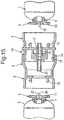
- a devicecomprising a container provided with engaging means and a mesh stack shuttle according to the invention, as disclosed in WO 02/41872-A1 , is shown in Figure 15 .
- the devicecomprises a low pressure container (1) for an aqueous sclerosant liquid and an unreactive gas atmosphere, a container (2) for a physiologically acceptable blood-dispersible gas and an engaging means comprising a connector (3).
- the container (2) for a physiologically acceptable blood-dispersible gasis charged at 5.8 bar absolute pressure with the required gas mixture, whereas the container (1) is charged with an inert gas.
- Container (2)is used to pressurise container (1) at the point of use to approx 3.5 bar absolute and is then discarded, just before the foam is required.
- the two containerswill thus be referred to hereinafter as the PD [polidocanol] can (1) and the 02 can (2), and the term "bi-can" will be used to refer to the concept of two containers.
- Each of the cans (1, 2)is provided with a snap-fit mounting (4, 5). These may be made as identical mouldings.
- the snap-fit parts (4, 5)engage the crimped-on mounting cup (6, 7) of each can (1, 2) with high frictional force.
- the connectoris made in two halves (8, 9), and the high frictional force allows the user to grip the two connected cans (1, 2) and rotate the connector halves (8, 9) relative to each other without slippage between connector (3) and cans.
- Each of these can mountings (6, 7)has snap-fit holes (10, 11) for engaging mating prongs (12, 13) which are on the appropriate surfaces of the two halves (8, 9) of the connector.
- the connector (3)is an assembly comprising a number of injection mouldings.
- the two halves (8, 9) of the connectorare in the form of cam track sleeves which fit together as two concentric tubes. These tubes are linked by proud pins (14) on one half that engage sunken cam tracks (15) on the other half.
- the cam trackshave three detented stop positions.
- the first of these detentsis the stop position for storage. An extra security on this detent is given by placing a removable collar (16) in a gap between the end of one sleeve and the other. Until this collar (16) is removed it is not possible to rotate the sleeves past the first detent position. This ensures against accidental actuation of the connector.
- the cam track sleeves (8, 9)are injection moulded from ABS as separate items, and are later assembled so that they engage one another on the first stop of the detented cam track.
- the assembled sleevesare snap-fitted as a unit onto the 02 can (2) mounting plate (5) via four locating prongs.
- the security collaris added at this point to make an 02 can subassembly.
- the connector (3)includes in its interior a series of foaming elements comprising a mesh stack shuttle (17) on the connector half (8) adjacent to the PD can (1).
- the mesh stack shuttle (17)is comprised of four injection moulded disk filters with mesh hole size of 20 ⁇ m and an open area of approx. 14%, and two end fittings, suitable for leak-free connection to the two canisters. These elements are pre-assembled and used as an insert in a further injection moulding operation that encases them in an overmoulding (18) that provides a gas-tight seal around the meshes, and defines the outer surfaces of the mesh stack shuttle.
- the end fittings of the stack (17)are designed to give gas-tight face and/or rim seals against the stem valves (19, 20) of the two cans (1, 2) to ensure sterility of gas transfer between the two cans.
- the mesh stack shuttle (17)is assembled onto the PD can valve (19) by push-fitting the components together in a aseptic environment.
- the PD can (1) and attached shuttle (17)are offered up to the connector (3) and the attached 02 can (2), and a sliding fit made to allow snap-fitting of the four locating prongs (12) on the PD can side of the connector (3) into the mating holes (10) in the mounting plate (4) on the PD can (1).
- the PD can valve (19)opens fully.
- the gas flow from the 02 can (2)is restricted by a small outlet hole (21) in the stem valve (20). It takes about 45 seconds at the second detent position for the gas pressure to (almost) equilibrate between the two cans to a level of 3.45 bar ⁇ 0.15 bar.
- the connector (3)is rotated further to the third detent position by the user.
- the two cans (1, 2)can be separated, leaving the PD can (1) with half (8) of the connector and the shuttle assembly (17) captive between the connector and the PD can.
- the 02 can (2)is discarded at this point.
- a standard 1 inch diameter aerosol valve (19)(Precision Valve, Peterborough, UK) is crimped into the top of the PD can (1) before or after sterile filling with the solution and may be activated by depressing the mesh stack shuttle (17), which functions as an aerosol valve actuator mechanism, to release the contents via an outlet nozzle (22) sized to engage a Luer fitting of a syringe or multi-way connector (not shown).
- All sample preparationwas performed under controlled laboratory conditions at temperatures within the range 18-22 degrees C, using polidocanol solution obtained from Kreussler 1% Aethoxysclerol.
- the containerwas a 100ml beaker.
- the beaker and the 10ml of solutionwas placed in a small glass aquarium tank which was modified to allow the internal space to be sealed from atmosphere, then flushed and flooded with the test gas mix.
- a flexible drive shaftwas attached to the micromotor to allow the micromotor to stay outside of the glass tank, whilst driving the brush inside the glass tank at the required speed. Where the flexible drive shaft entered the glass tank, it was sealed to avoid leaks from atmosphere
- the flushing of the glass tankwas performed for 30 seconds with the gas mix supplied at 0.2 bar above atmospheric pressure to the glass tank. After the 30 second flush, the regulator was turned down to allow a trickle of ingressing gas for the rest of the experiment. The speed of rotation and duration of whipping was fixed at 11500 rpm and 90 seconds.
- Example 1Polidocanol, glycerol and CO 2 foams
- Foamswere made with polidocanol, glycerol and CO 2 using various techniques.
- the technique used to make the foamplays an important role in the half life and density of the resulting foam.
- 500ml of a buffered solution of 1% polidocanol and 30% glycerolwas made up using the following procedure. 100 % polidocanol pd ⁇ a waxy solid ⁇ was melted by placing in a bath of warm water
- Distilled waterwas added to make up to 500g on scale
- the solutionwas filtered through a 0.25micron filter.
- the carbon dioxide and pd/glycerol solutionwere then manually pumped back and forth between the two syringes as fast as possible for in excess of 30 cycles. A foam formed in the syringes during this process. After the final cycle, the foam was quickly transferred to half-life and density measuring apparatus and the half life and density of the foam determined.
- a so called “mesh stack” devicewas prepared having a flow path which incorporated a series of four mesh elements. Each mesh element measured about 2-3mm in diameter and had pores with diameter 5 micron. At each end of the device was a luer connection.
- Pressurised canisters with a capacity of approximately 100mlwere made up with about 20ml of buffered polidocanol/glycerol solution. The canisters were then pressurised with substantially pure carbon dioxide to a pressure of 3.5bar absolute.
- the canistersare each fitted with a valve, with a dip tube extending from the valve to the base of the canister. On each side of the valve are apertures which draw in gas as liquid passes up the dup tube under pressure. Above the valve, each canister is fitted with a mesh stack unit as described above.
- the foam produced by the 30% glycerol solutionwas relatively stiff and formed a compact, rounded blob on a surface.
- the blobcould be seen to start decaying within a few seconds, but remained as a blob rather than a liquid puddle for much longer. Observations were not recorded for the 40% glycerol.
- Viscositywas determined at 23oC using the Brookfield device described above.
- Foamswere prepared using the polidocanol (PD) and different percentages of viscosity enhancing agents (wt/wt) and the Cabrerra method described above. The half life and density of the resulting foam was determined as described above. Similar experiments can be used to determine if a particular combination of viscosity enhancing agent, sclerosing agent, and gas provide a foam with a suitable half-life and density. Foams were also produced using a canister as described above and the results are presented in Table 16.
- Table 16Canister CO2/glycerol results Composition (all compositions are 100% CO2 & 1% polidocanol) Density (g/ml) Half life (seconds) Overage Density (g/ml) Average Half life (seconds) Viscosity of Liquid Component (cP) 5% glycerol 0.105 76 0.112 63 1.5 5% glycerol 0.109 58 5% glycerol 0.111 60 5% glycerol 0.117 59 5% glycerol 0.121 61 10% glycerol 0.112 78 0.117 76 1.6 10% glycerol 0.115 75 10% glycerol 0.118 78 10% glycerol 0.124 73 20% glycerol 0.113 92 0.115 96 2.2 20% glycerol 0.113 99 20% glycerol 0.113 104 20% glycerol 0.120 95 20% glycerol 0.114 90 25% glycerol 0.105 111 0.109 111 2.6
Landscapes
- Health & Medical Sciences (AREA)
- Chemical & Material Sciences (AREA)
- Life Sciences & Earth Sciences (AREA)
- Veterinary Medicine (AREA)
- Public Health (AREA)
- General Health & Medical Sciences (AREA)
- Animal Behavior & Ethology (AREA)
- Engineering & Computer Science (AREA)
- Pharmacology & Pharmacy (AREA)
- Medicinal Chemistry (AREA)
- Surgery (AREA)
- Epidemiology (AREA)
- Chemical Kinetics & Catalysis (AREA)
- Dispersion Chemistry (AREA)
- Heart & Thoracic Surgery (AREA)
- Nuclear Medicine, Radiotherapy & Molecular Imaging (AREA)
- Biomedical Technology (AREA)
- Molecular Biology (AREA)
- Medical Informatics (AREA)
- Vascular Medicine (AREA)
- General Chemical & Material Sciences (AREA)
- Reproductive Health (AREA)
- Bioinformatics & Cheminformatics (AREA)
- Inorganic Chemistry (AREA)
- Oil, Petroleum & Natural Gas (AREA)
- Organic Chemistry (AREA)
- Mechanical Engineering (AREA)
- Anesthesiology (AREA)
- Hematology (AREA)
- Dermatology (AREA)
- Rheumatology (AREA)
- Cardiology (AREA)
- Pharmaceuticals Containing Other Organic And Inorganic Compounds (AREA)
- Medicinal Preparation (AREA)
- Infusion, Injection, And Reservoir Apparatuses (AREA)
- Polyurethanes Or Polyureas (AREA)
- Manufacture Of Porous Articles, And Recovery And Treatment Of Waste Products (AREA)
- Emulsifying, Dispersing, Foam-Producing Or Wetting Agents (AREA)
- Medicines That Contain Protein Lipid Enzymes And Other Medicines (AREA)
- Acyclic And Carbocyclic Compounds In Medicinal Compositions (AREA)
Abstract
Description
- The present invention relates to the generation of foam comprising a sclerosing material, particularly a sclerosing solution, which is suitable for use in the treatment of various medical conditions involving blood vessels, particularly varicose veins and other disorders involving venous malformation.
- Sclerosis of varicose veins is based on the injection into the veins of liquid sclerosant substances which, byinter alia causing a localised inflammatory reaction, favour the elimination of these abnormal veins. Until recently, sclerotherapy was a technique selected in cases of small and medium calibre varicose veins, those with diameters equal to or greater than 7 mm being treated by surgery.
- An injectable microfoam suitable for therapeutic use, on larger veins in particular, has now been developed and is described in
EP-A-0656203 andUS 5676962 (Cabrera & Cabrera). These describe a low-density microfoam produced with a sclerosing substance which, when injected into a vein, displaces blood and ensures that the sclerosing agent contacts the endothelium of the vessel in a known concentration and for a controllable time, achieving sclerosis of the entire segment occupied. - The Cabreras proposed the use of a microfoam, that is to say a microfoam with microscopically small bubbles,e.g., where the majority of the bubbles are not visible to the naked eye, for injection into varicose veins. The use of a microfoam, as opposed to larger bubbled foam or froth, gives rise to many advantages in terms of controllability and ability to displace blood in even the largest varicose veins, allowing treatment of virtually all varicose veins without recourse to surgery. As used here, the term foam encompasses foams with bubbles of all sizes including microfoams.
- The first teaching that potential issues with intravenous injection of a microfoam product made with air are serious enough to warrant change is to be found in the Cabrera patent references mentioned above. These documents indicate that the prior air based techniques are "dangerous owing to the side effects of atmospheric nitrogen which is only slightly soluble in blood", though it is not mentioned exactly what the dangers are nor what volumes or rates of injection of air or nitrogen gas give rise to these dangers.
- In addition to being the first to propose a microfoam as opposed to a larger bubbled foam, and to propose treatment of even the largest veins without surgery, the Cabreras also proposed that the microfoam be made with oxygen or a mixture of carbon dioxide and oxygen. In the context of this background, the Cabreras' contribution can be seen to be highly innovative in a number of respects - appreciating against the prevailing thinking at the time (i) the potential of a sclerosant microfoam, (ii) the need for soluble gases, (iii) the use of oxygen which does not degrade the microfoam yet is taken up by blood, (iv) the safety of oxygen but also (v) the possibility of incorporating a percentage of highly soluble carbon dioxide.
- The Cabreras' microfoam is prepared extemporaneously in the clinic immediately prior to use. The preparation involves beating sclerosant solution with a small brush rotated at high speed by a motor, under a cover which is connected to a source of oxygen or oxygen and carbon dioxide. Most practitioners who have followed the Cabreras use an alternative technique for extemporaneous preparation of foam which involves passing sclerosant solution and air repeatedly between two connected syringes. Another alternative is a syringe with a second plunger with holes in its face and which is independently movable in the syringe barrel to froth a liquid and gas mixture in the syringe. Both of these latter types of procedure are somewhat inconvenient and allow for variation of the foam composition depending upon the person preparing it: gas content, bubble size, density and stability all require attention. These techniques require a high degree of care and knowledge that may be difficult to replicate under pressure, i.e. when time available to prepare the foam is short.
- A product which aims essentially to reproduce the Cabreras' microfoam in a more convenient and easily reproducible way is currently being developed and is in clinical trials in Europe and the USA. This product is a pressurised canister system, in which the foam is produced by passing gas and sclerosant solution under pressure through a number of fine meshes. In the trials of this product the aim is to treat an entire long saphenous vein and its varicosed tributaries in a single treatment, which can mean injection of 25ml or even 50ml of foam.
WO 00/72821-A1 WO 00/72821-A1 - In a later patent application,
WO 02/41872-A1 - The device disclosed in
WO 02/41872-A1 WO 00/72821-A1 - The present inventors are continuing to research clinical aspects of the injection of sclerosing foam as well as developing the canister foam product and putting it through clinical trials in Europe and the USA. It has always been the intention to develop a safe foam product which is as well defined as possible but whose specification has achievable tolerances. There are many parameters of a foam which may be varied. These include, without limitation: the chemical, its purity and the strength of the solution; the size of bubbles, or more accurately the distribution of sizes, the density (i.e. ratio of liquid to gas), the longevity of the foam (measured in terms of "half life", or the time taken for half the foam to revert to liquid) and the gas mixture.
- Nitrogen, which makes up approximately 80% of air, is difficult as a practical matter to exclude totally from a foam. This is true whether the foam is made using a canister system, in which case nitrogen tends to creep into the canister during manufacture, or using either of the syringe techniques or the Cabreras' rotating brush technique, or indeed any of a number of other less common techniques which have been developed since the Cabreras' disclosure of microfoam.
- One of the objectives of the foam product being developed by the inventors is to treat an entire greater saphenous vein together with major varicose tributaries in a human patient with one injection. This requires up to 25ml, 30ml or possibly even 50ml of foam.
- The inventors also recognise that techniques such as those described above using syringes, together with a variety of other techniques for extemporaneous preparation of sclerosing foam which have been developed since the Cabreras disclosure, may have their place in the field of foam scleropathy. These techniques may well provide a less expensive option than a canister product. The inventors believe that it is possible to prepare foams having a very low percentage of nitrogen, as set out above, using these types of technique as well as using a canister system.
- As suggested by Cabrera and discussed above, one could use oxygen or mixtures of oxygen and carbon dioxide of the gas component. Carbon dioxide is very soluble in water (and hence blood) and oxygen is not very soluble in water but is taken up relatively rapidly by haemoglobin in blood. The present inventors have also done studies that have shown that CO2 and 02 are taken up in blood much faster than N2 or air. However, foams made solely with carbon dioxide, or other highly water-soluble gases, tend to be very unstable and do not last long enough to be usable. Because CO2 foams have a very short half life, foams with a high concentration of CO2 have not been used in the past to prepare foams for sclerotherapy.
- For example, a predominantly insoluble gas mix such as air will yield a stable, stiff foam with a half separation time of 150-200 seconds using the Cabrera method. However, highly soluble gas atmospheres such as 100% CO2 yield foams with much shorter half separation times. It is thought that the rapid dissolution and transport of CO2 in the lamellar cell walls of the foam is responsible for the reduced stability of some CO2 foams. This allows the smaller, high pressure bubbles of the foam to rapidly transfer all their gas content to adjacent larger low pressure bubbles, which then rise through the foam to burst or accumulate at a surface. This process is called Ostwalt ripening, and with all-CO2 foams the liquid cell wall is no longer a significant barrier to diffusion between adjacent bubbles at different Laplace pressures. Drainage and separation of foam into gas and liquid components is also influenced by the viscosity of the liquid component.
- Oxygen foams do not have this problem, but the injection of oxygen gas has been reported to be dangerous and, in fact, has been said to be almost as dangerous as air when injected into the venous system. See, for example,Moore & Braselton "Injections of Air and carbon Dioxide into a Pulmonary Vein", Annals of Surgery, Vol 112, 1940, pp 212-218. While another study suggests that for some high risk patient groups high concentrations of 02 in foams used for sclerotherapy may increase the risk of side effects.
- Recent studies have also suggested that foams for sclerotherapy made with high concentrations of N2 or 02 may lead to potential side effects in certain patient groups. More specifically, one study suggests that high concentrations of nitrogen may lead to a higher risk of arterial embolism in certain patient populations.
- The present inventors, however, have discovered that it is possible to make an effective foam for use in sclerotherapy using high concentrations of CO2 as the gas phase and the addition of a viscosity enhancing agent to the liquid phase. The addition of a viscosity enhancing agent, however, while increasing the half life of a CO2 foam, also increases the density of the foam. Too high of a density can hinder a foams ability to displace blood and therefore be an effective foam for sclerotherapy. It was discovered that a balance of density and half life enables the production of an effective foam. In one embodiment, this balance of density and half life is achieved by increasing the viscosity enhancing agent to at least 20% wt/wt and using various methods as described herein to produce the foam.
- Accordingly, the present invention provides a foam as described in
claim 1. - Viscosity enhancing agents include any agent that will increase the viscosity of the liquid phase, such as PVP and glycerol. In one embodiment, at least 20% wt/wt viscosity enhancing agent is present in the liquid phase, such as for example 25%, 30%, 35%, 40%.
- Viscosity of the liquid phase before production of the foam may also be a factor in the half life of the foam. For example, increasing viscosity of the liquid phase will increase half life of the foam. However, a higher viscosity may raise the density of the resulting foam in some systems.
- Thus the foam of the invention comprises a liquid phase and a gas phase wherein the liquid phase comprises at least one sclerosing agent and is at least 20% wt/wt of at least one viscosity enhancing agent; and the gas phase comprises at least 90% CO2; and wherein the foam has a density less than 0.25 g/cm and half life of greater than 100 secs. The gas phase may, for example be at least 99% CO2. In one embodiment, the gas phase consists essentially of CO2.
- The foam, for example, may have a half life of at least 100, such as at least 110, such as at least 120 seconds, such as at least 130 seconds, such as at least 140 seconds, such as at least 150 seconds, such as at least 160 seconds, such as at least 170 seconds, such as at least 180 seconds, and such as at least 3.5 minutes. The density of the foam may range from 0.07 to 0.22, such as 0.07 to 0.19 g/ml, 0.07 to 0.16 g/ml, such as 0.08 to 0.14, also such as 0.8 to 0.15 g/ml, such as 0.9 to 0.13 g/ml and such as 0.10 to 0.14 g/ml. The gas phase may further comprises another physiologically acceptable gas that is dispersible in blood, such as 02. The viscosity of the liquid phase may range from 2.0 to 10 cP, such 2.0 to 7.0 cP, such as 2.0 to 5.0 cP, such as 2.0 to 3.5 cP, such as from 2.0 to 3.0 cP, such as 2.0 ta 2.5 cP.
Figure 1 is a schematic representation of a syringe barrel part of a device which may be used in accordance with the invention, showing it in a sealed state for storage;Figure 2 is a schematic representation of a cartridge for use with the syringe barrel ofFigure 1 ;Figure 3 is a schematic representation of a modified cartridge for use with the syringe barrel ofFigure 1 ;Figure 4 is a further schematic representation of the syringe barrel ofFigure 1 with a cartridge of the type shown inFigure 3 being installed;Figure 5 is a further schematic representation of the syringe barrel ofFigure 1 with a foaming unit and plunger stem fitted;Figure 6 is a schematic representation of the syringe, cartridge and foaming device ofFigure 5 , with the plunger stem of the syringe partially depressed;Figure 7 is a schematic representation of a second embodiment of device in accordance with the invention, comprising charged syringe with foaming unit fitted;Figure 8 is a schematic representation of the device ofFigure 7 installed in a syringe driver for generation and delivery of foam at a controlled rate;Figure 9 is a schematic representation of an alternative device according to the invention;Figure 10 is a schematic representation of the device ofFigure 9 fitted to a motorized driver;Figure 11 is a plan view of a mesh element of an embodiment of a foaming unit forming part of the invention;Figure 12 is a side sectional view along the line I-I inFigure 11 ; andFigure 13 is a side sectional view of an embodiment of foaming unit forming part of the invention.Figure 14 shows a cross-sectional view of a pre-pressurised container for the generation of therapeutic foam according to the invention, as disclosed inWO 00/72821-A1 Figure 15 shows a shows a cross-sectional view of a device comprising a container provided with engaging means and a mesh stack shuttle according to the invention, as disclosed inWO 02/41872-A1 Figure 16 shows the effects of (a)glycerol concentration on viscosity of the liquid phase before mixing with the gas phase to form a foam and (b) the effects of various viscosity enhancing agents on viscosity of the liquid phase.Figure 17 (a, b, and c) shows the effects of various viscosity enhancing agents on the density and half life of a Cabrerra foam.- For the purpose of this application terms have the following definitions: A sclerosant liquid is a liquid that is capable of sclerosing blood vessels when injected into the vessel lumen. Scleropathy or sclerotherapy relates to the treatment of blood vessels to eliminate them. An aerosol is a dispersion of liquid in gas. A major proportion of a gas is over 50% volume/volume. A minor proportion of a gas is under 50% volume/volume A minor amount of one liquid in another liquid is under 50% of the total volume. Atmospheric pressure and bar are 1000 mbar gauge. Half-life of a foam is the time taken for half the liquid in the foam to revert to unfoamed liquid phase.
- In one embodiment, the foam is such that 50% or more by number of its gas bubbles of 25 µm diameter and over are no more than 200 µm diameter.
- Half-life is conveniently measured by filling vessel with a known volume and weight of foam and allowing liquid from this to drain into a graduated vessel, the amount drained in a given time allowing calculation of half-life i.e. of conversion of foam back into its component liquid and gas phases. This is preferably carried out at standard temperature and pressure, but in practice ambient clinic or laboratory conditions will suffice.
- As used here, the viscosity is determined by Brookfield DVII+Pro made by Brookfield Engineering Labs at room temperature.
- The mixture of gas and sclerosant liquid is in the form of a macrofoam. By macrofoam is meant a foam that has gas bubbles that are measured in millimetres largest dimension, e.g. approximately 1 mm and over, and over such as can be produced by lightly agitating the two phases by shaking. It may be that a macrofoam is first produced where the liquid and gas are brought together only at the point of use.
- The ratio of gas to liquid used in the mixture may be important in order to control the structure of the foam produced such that its stability is optimized for the procedure and the circumstances in which it is being carried out. For some foams, one may mix 1 gram sclerosant liquid with from approximately 6.25 to 14.3 volumes (STP), more preferably 7 to 12 volumes (STP), of gas.
- The sclerosing agent is a solution of polidocanol or sodium tetradecylsulfate in an aqueous carrier, e.g. water, particularly in a saline. Preferably the solution is from 0.5 to 5% v/v polidocanol, preferably in sterile water or a physiologically acceptable saline, e.g. in 0.5 to 1.5% v/v saline. Concentration of sclerosant in the solution will be advantageously increased for certain abnormalities such as Klippel-Trenaunay syndrome.
- Polidocanol is a mixture of monolauryl ethers of macrogols of formula C12C25(OCH2CH2)nOH with an average value of n of 9. It will be realized that mixtures with other alkyl chains, oxyalkyl repeat units and/or average values of n might also be used, e.g. 7 to 11, but that 9 is most conveniently obtainable, e.g. from Kreussler, Germany, e.g. as Aethoxysklerol™, a dilute buffered solution of polidocanol.
- The concentration of sclerosant in the aqueous liquid is a 1-3% vol/vol solution, such as polidocanol, in water or saline, such as about 1% vol/vol. The water or saline also, in some cases at least, contain 2-4% vol/vol physiologically acceptable alcohol, e.g. ethanol. Saline may be buffered. Some buffered saline is phosphate buffered saline. The pH of the buffer may be adjusted to be physiological, e.g. from pH 6.0 to pH 8.0, more preferably about pH 7.0.
- Another aspect of the present invention is a method for producing a foam suitable for use in scleropathy of blood vessels, particularly veins, characterized in that it comprises passing a mixture of gas and an aqueous sclerosant liquid through one or more passages having at least one cross-sectional dimension of from 0.1 to 15 µm, the ratio of gas to liquid being controlled such that a foam is produced having a density of between 0.07 g/mL to 0.19 g/mL and a half-life of at least 100 seconds, such as 2 minutes, such as 2.5 minutes.
- Preferably, the said one or more passages have at least one cross-sectional dimension of from 1-7 micron, more preferably about 5 micron.
- In accordance with the original specification (as set out in
WO00172821-A1 WO00/72821-A1 - According to an aspect of the invention a sclerosant foam is composed of bubbles of which, ignoring bubbles of 1 micron or less diameter, 95% or more are of 150micron diameter or less and 50% or more are of 100micron diameter or less. Preferably, 95% or more of the bubbles are of 100micron diameter or less and 50% or more of the bubbles are of 50micron diameter or less. More preferably, 95% or more of the bubbles are of 75micron diameter or less and 50% or more of the bubbles are of 30micron diameter or less. Still more preferably, 95% or more of the bubbles are of 60micron diameter or less and 70% or more of the bubbles are of 30micron diameter or less. Examples are presented below showing how foams with these sorts of bubble distributions have been made.
- These very small bubble foams have only to date been obtained by the inventors by having a relatively dense formulation of the order of 0.3 to 0.5 g/ml, with a relatively high ratio of liquid to gas. Such a wet foam is still considerably less dense than blood and therefore will be buoyant when in a vein full of blood. It is speculated that this buoyant characteristic may to some extent be responsible for the advantageous behaviour of foam in the vascular system in terms of displacing blood. However, the dense foams produced to date by the inventors behave essentially as a liquid in terms of their rheological properties - they are not "stiff'.
- It is not impossible that these dense but somewhat fluid foams may have a sufficiently good therapeutic effect to be useful and may also eliminate or reduce the residual gas problem. However, it is probable that the rheological properties of the foam in blood are important, and that a "stiff" foam is desirable effectively to displace blood and thus allow consistent, uniform application of the active to the interior of the vessel wall. For this reason it is desirable to add a further ingredient to the foam in order to increase its stiffness/viscosity, either by adding a viscosity-enhancing additive to the formulation or by adding an agent which increases the foaming capacity of the formulation.
- Such ingredients could be, without limitation,
Polysorbate 20,Polysorbate 80 or Polygeline. Alternatively, glycerol and PVP may be added. - A foam with a bubble size distribution falling within the definitions set out above may be created by passing gas and liquid repeatedly through a fine mesh, e.g. a 5 micron mesh. Repeated passages through the mesh reduce the bubble size, though there appears to be a limit on this.
- It is envisaged that other known techniques for agitating a gas and liquid mixture at high energy could be applied to make even finer bubbles. For example sonic or ultrasonic agitation of a mixing stream of gas and liquid could be used, or alternatively a mixture of beating the gas and liquid by mechanical means, supplemented by the application of sonic or ultrasonic energy.
- The inventors have also prepared a foam having an average bubble size in the range 50micron to 80micron by adapting a canister to alter the ratio of liquid and gas being passed through a mesh.
- A further aspect of the invention is a device according to
claim 12, which is a pressurised canister product adapted to dispense a sterile gas and sclerosing liquid mixture in predetermined proportions into a syringe, as a solution to some of the issues with extemporaneous preparation of foam. Thus a pressurised canister is provided - which may be of any suitable material such as anodised aluminium or even glass - containing sterile gas and sclerosing liquid and arranged to dispense the correct volume of liquid and gas into a syringe. It is envisaged that the canister would contain sterile gas with a very low nitrogen concentration etc. as defined above. The canister may have a pierceable septum for puncturing with a hypodermic needle, or it may have a break seal which is arranged to be broken by insertion of a syringe luer nozzle. - In the latter case, a syringe luer nozzle could be inserted into the canister in a sealing fashion, with the syringe nozzle pointing upwards. Liquid in the canister would be dispensed first under pressure, followed by equalisation of the pressure in the canister and syringe. The pressure and volume of gas in the canister could of course be arranged so that the correct proportions of gas and liquid are dispensed. Alternatively, the canister could be provided with an internal dip tube so that the same effect is achieved with the canister in an upright orientation.
- Another embodiment of the present invention provides a foam, that, for example, can be used in the elimination of blood vessels and vascular malformations, that are made available by the method and devices of the invention, comprising a physiologically acceptable gas that is readily dispersible in blood together with an aqueous sclerosant liquid wherein in that the foam has a density of from 0.07 to 0.19 g/cm.
- In one embodiment, the foam is capable of being passed down a 21 gauge needle without reverting back to gas and liquid by more than 10%, based on liquid content reverting back to unfoamed liquid phase.
- Half-life is conveniently measured by filling vessel with a known volume and weight of foam and allowing liquid from this to drain into a graduated vessel, the amount drained in a given time allowing calculation of half-life i.e. of conversion of microfoam back into its component liquid and gas phases. This is preferably carried out at standard temperature and pressure, but in practice ambient clinic or laboratory conditions will suffice.
- Most conveniently the funnel is pre-equilibrated in a water bath to ensure a temperature of 25°C before drying and application of foam. Placing of a foam filled syringe upside down, without its plunger, above the funnel leading into a graduated receptacle allows convenient measurement of this parameter.
- In one embodiment, the foam, on passage through said needle, does not revert back to unfoamed liquid by more than 5% based on liquid content, still more preferably by no more than 2%. This is measured by measuring the change in volume of the foam versus the liquid.
- In one embodiment, the foam is capable of being passed down a needle while retaining at least 50% by number of its gas bubbles of at least 25 µm diameter at no more than 200 µm diameter. This is conveniently measured under ambient conditions, more preferably at STP.
- In one embodiment, the gas includes less than 40% v/v nitrogen. Preferably the density of the foam is from 0.09 to 0.16 g/mL, more preferably 0.11 g/mL to 0.14 g/mL.
- In one embodiment, the foam density, which is a measure of liquid/gas ratio, is from 0.13 to 0.14 g/cm and the half-life is at least 2.5 minutes. The foam more preferably does not move outside of its parameters of bubble size set out above in such time.
- In one embodiment, the gas consists of at least 99% carbon dioxide, e.g. substantially 100% carbon dioxide. Preferably the carbon dioxide is medical grade.
- As discussed above, addition of glycerol to the aforesaid sclerosant imparts a longer half-life to the resultant foam. However, glycerol may increase density and also produces a tendency for the meshes to block up when using a mesh device as described above, so should be used carefully where the device it is produced from may be used multiple times or the bag-on-valve concept is used.
- Accordingly the one aspect of the present invention provides a method for producing a foam suitable for use in scleropathy of blood vessels, particularly veins, as described in
claim 11, and characterized in that it comprises passing a mixture of a physiologically acceptable blood dispersible gas and an aqueous sclerosant liquid through one or more passages having at least one cross-sectional dimension of from 0.1 to 15 µm, the ratio of gas to liquid being controlled such that a foam is produced having a density of between 0.07 g/mL to 0.19 g/mL and a half-life of at least 100 seconds. - Devices for producing a foam suitable for use in scleropathy of blood vessels, particularly veins, comprise a housing in which is situated a pressurisable chamber containing a solution of the sclerosing agent in a physiologically acceptable solvent referred to above; a pathway with one or more outlet orifices by which the solution may pass from the pressurisable chamber to exterior of the device through said one or more outlet orifices and a mechanism by which the pathway from the chamber to the exterior can be opened or closed such that, when the container is pressurized and the pathway is open, fluid will be forced along the pathway and through the one or more outlet orifices
said housing incorporating one or more of (a) a pressurized source of physiologically acceptable gas that is dispersible in blood and (b) an inlet for the admission of said gas; the gas being in contacted with the solution on activation of the mechanism such as to produce a gas solution mixture
said pathway to the exterior of the housing including one or more elements defining one or more passages of cross sectional dimension, preferably diameter, 0.1 µm to 15 µm, through which the solution and gas mixture is passed to reach the exterior of the device, said passing of said mixture through the passages forming a foam of from 0.07 to 0.19 g/mL density and of half-life at least 2 minutes. - Preferably the apparatus includes a chamber, e.g. such as in a sealed canister, charged with the blood dispersible gas and the sclerosant liquid, e.g. in a single chamber, the device pathway including a dip tube with an inlet opening under the level of the liquid in this chamber when the device is positioned upright. Preferably the dip-tube has an outlet opening at a gas liquid interface junction where the gas, which resides in the chamber above the liquid, has access to the pathway to the device outlet. The pathway is opened or closed by a valve element which is depressed or tilted to open up a pathway to the exterior of the device, whereby the liquid rises up the dip tube under gas pressure and is mixed in the interface junction with that gas to produce an aerosol, dispersion of bubbles in liquid or macrofoam.
- Either inside the pressurisable chamber disposed in the pathway to the valve, or on the downstream side of the valve, is provided an element having the one or more passages described in the first aspect mounted such that the gas liquid mixture, i.e. dispersion of bubbles in liquid, aerosol or macrofoam" passes through the passage or passages and is caused to foam. This element may conveniently be located in a cap on the canister in between the valve mounting and an outlet nozzle. Conveniently depression of the cap operates the valve. Alternatively the element is within the canister mounted above the gas liquid interface.
- In an alternate embodiment of this device the gas liquid interface may comprise holes in the dip tube above the level of the liquid in the canister inner chamber.
- The gas pressure employed will be dependent upon materials being used and their configuration, but conveniently will be 0.01 to 9 bar over atmospheric, more preferably 0.1-3 bar over atmospheric, and still more preferably 1.5-1.7 bar over atmospheric pressure.
- A preferred device of this aspect of the invention is of the 'bag-on-valve' type. Such device includes a flexible gas and liquid tight container, forming a second inner chamber within the pressurisable chamber, which is sealed around the dip-tube and filled with the liquid. More preferably the dip-tube has a one-way valve located at a position between its end located in the sclerosant liquid and the gas liquid interface junction, which when the passage to the exterior is closed, remains closed such as to separate the liquid from the physiologically acceptable blood dispersible gas around it in the chamber. On opening the pathway to the exterior, the one way valve also opens and releases liquid up the dip-tube to the gas liquid interface where an aerosol is produced which is in turn then passed through the passages to be converted to foam. A suitable one-way valve is a duck-bill type valve, e.g. such as available from Vernay Labs Inc, Yellow Springs, Ohio, USA. Suitable bag-on-valve can constructions are available from Coster Aerosols, Stevenage, UK and comprise an aluminium foil/plastics laminate.
- Conveniently the one way valve is located at the top of the dip-tube between that and the gas liquid interface junction, i.e. an Ecosol device. This allows filling of the bag before application of the one way valve, followed by sterilization of the contents, whether in the canister or otherwise.
- Such a preferred device has several potential advantages. Where oxygen is the gas, this is kept separate from the liquid before use and thus reduces possibility of oxygen radicals reacting with organic components in the liquid, e.g. during sterilization processes such as irradiation. Where carbon dioxide is the gas, storage can lead to high volumes of gas dissolving in the liquid, which on release to the atmosphere or lower pressure, could out-gas and start to destroy the foam too quickly. Such separation also prevents the deposition of solidified sclerosing agent components in the dimension sensitive orifices of the device in an unused can in storage or transit, particularly should that be oriented other than upright.
- It is preferred that the gas liquid interface is provided as a defined orifice size device such as the Ecosol device provided by Precision Valve Peterborough UK. For a device where the passages of defined dimension are outside of the pressurized chamber, i.e. mounted on the valve stem, the ratio of area of the gas holes to the liquid holes should be of the order of 3 to 5, preferably about 4. Where the passages are inside the pressurized chamber this is preferably higher.
- Another aspect of the invention provides a device for producing a foam suitable for use in sclerotherapy of blood vessels, particularly veins, comprising a housing in which is situated a pressurisable chamber, at least part filled or fillable with a solution of a sclerosing agent in a physiologically acceptable solvent and/or a physiologically acceptable blood dispersible gas; a pathway by which the contents of the chamber may be passed to exterior of the housing through one or more outlet orifices and a mechanism by which the chamber can be pressurized such that its contents pass to the exterior along the pathway and through one or more outlet orifices
said pathway to the exterior of the housing or the chamber including one or more elements defining one or more passages of cross sectional dimension, preferably diameter, 0.1 µm to 15 µm through which the contents of the chamber may be passed, whereby on passing through the passages the solution and gas form a foam of from 0.07 to 0.19 g/mL density and having a half-life of at least 2 minutes. - The elements defining the passages in the pathway or chamber may be static or may be moveable by manipulation of the device from outside of its interior chamber.
- Preferably the housing is a container defining a chamber in which is situated the solution and gas under pressure and the pathway is a conduit leading from the chamber in the interior of the container to a valve closing an opening in the container wall.
- Preferred forms of the one or more elements defining the multiple passages for use in the device of the present invention are meshes, screens or sinters. Thus one or more meshes or perforated screens or sinters will be provided, with some preferred forms employing a series of such elements arranged in parallel with their major surfaces perpendicular to the path of solution/gas expulsion.
- It is preferred that all elements of any of the devices according to the invention having a critical dimension are made of a material that does not change dimension when exposed to aqueous material. Thus elements with such function such as the air liquid interface and the element defining the passages of 0.1 µm-15 µm dimension preferably should not be of a water swellable material such as Nylon 66 where they are likely to be exposed to the solution for more than a few minutes. Where such exposure is likely these parts are more preferably being fashioned from a polyolefin such as polypropylene or polyethylene.
- Preferably the canister is sized such that it contains sufficient gas and solution to form up to 500 mL of foam, more preferably from 1 mL up to 200 mL and most preferably from 10 to 60 mL of foam. Particularly the amount of gas under pressure in such canisters should be sufficient to produce enough foam to treat, i.e. fill, at least one varicosed human saphenous vein. Thus preferred canisters of the invention may be smaller than those currently used for supply of domestic used mousse type foams. The most preferred canister device is disposable after use, or cannot be reused once opened such as to avoid problems of maintaining sterility.
- It may be preferred to incorporate a device which maintains gas pressure in the canister as foam is expelled. Suitable devices are such as described under trademarked devices PECAP and Atmosol. However, where a significant headspace or pressure of gas is provided this will not be necessary.
- The canister system has some drawbacks, however. It is relatively complex and thus expensive. Furthermore, the initial quantity of foam generated using a canister system can be of unpredictable quality and thus tends to be diverted off to waste prior dispensing foam for use. It is not easy to deliver foam direct from a pressurized canister into a cannula in a patient's vein; although this is theoretically possible, it would require special valve/control arrangements on the canister output to allow for the delivery rate to be highly controllable by the clinician administering the treatment. A further issue is that, whenever dispensing of foam is stopped or slowed significantly, it is necessary on re-starting to divert a quantity of foam to waste again before dispensing usable foam.
- For all these reasons, the canister product mentioned above, though a well designed and highly effective system, is designed to deliver foam product into a syringe for subsequent administration to a patient. A special foam transfer unit is used for this purpose. The syringe nozzle is inserted into a port on this transfer device and the device is then used to divert the first portion of foam before charging the syringe with usable foam.
- A further issue is that the foam, once made, immediately starts to change - liquid drains out and bubbles coalesce. A period of time is required time for the clinician to divert an initial quantity of foam from a canister, charge a syringe with good foam, connect it to a line to a patient's vein and administer the foam. This time will vary with different clinicians and even the same clinician will not always take the same length of time. Furthermore, each treatment is different and the foam will be injected over a different period; sometimes the clinician will stop dispensing foam for a short period and then recommence. All this time, the properties of the foam will be changing.
- There are other techniques for generating foam for use in sclerotherapy, including the so called "Tessari" and "DSS" techniques, each of which involves pumping liquid sclerosant and gas between two syringes. These two techniques are widely used for generating sclerosing foams made with air, and there are also a number of other less widely used techniques. Although these techniques are simpler than a canister system, they offer no solutions to the problems mentioned above and they also have their own problems such as unpredictability of the product and the difficulty in using any gas other than ambient air.
- Further features and advantages of the invention will be apparent from the following description of various specific embodiments, which is made with reference to the accompanying drawings:
- One embodiment of a device according to the invention comprises a syringe type device comprising a syringe barrel having an annular chamber containing gas and a central chamber for receiving a cartridge of sclerosant solution, e.g. 1% polidocanol solution.
Figure 1 shows asyringe barrel 1 in a storage condition with its open ends closed withseals 2 of metal/plastic laminate material. Thebarrel 1 comprises an outercylindrical wall 3 having a conicaltapered end portion 4 at the front, from which extends astandard luer nozzle 5. Disposed within the outer cylindrical wall is an innercylindrical wall 6 defining aninner chamber 14. The front of theinner wall 6 is partly closed by andend face 8, in which is formed anorifice 9 with afrangible seal 10. The inner wall is supported at the front end by aweb 11, in which apertures 12 are formed. - The outer and
inner walls annular space 7 which is filled with substantially 100% pure carbon dioxide gas. Theannular space 7 communicates with the interior space of theluer nozzle 5 via theapertures 12 in theweb 11. Located at the rear of the barrel, in theannular space 7, is anannular plunger seal 13 of resilient plastics material which seals against the outer and innercylindrical walls Figure 2 shows a cartridge comprising aglass tube 20 filled with 1 % polidocanol and sealed at each end by aresilient plastics bung 21. One or both of the bungs may function as a plunger seal, that is to say it may be movable down the length of the tube whilst retaining a sealing contain with the interior wall of the tube. The cartridge ofFigure 2 is not suitable for use with the syringe barrel described above, but could be used with a modified version of the barrel as discussed below.Figure 3 shows a cartridge suitable for use with the syringe barrel described above with reference toFigure 1 . The cartridge comprises aglass tube 30 which is filled with 1% polidocanol solution. At the rear end of thetube 30 is aresilient bung 31 which is capable of functioning as a plunger seal as described above. At the front end of the tube is anend face 32 in which is located anozzle 33, sealed with anend cap 34. The size and shape of thetube 30 complements the shape of theinner wall 6 of the syringe barrel ofFigure 1 . In particular, the diameter of thetube 30 is such that the tube is a close fit in theinterior space 14 defined within theinner wall 6 of thebarrel 1, and thenozzle 33 of the cartridge is sized so that, when fully inserted into theinterior chamber 14 of the barrel, it protrudes through theorifice 9 in the front of the chamber 14 (theend cap 34 having first been removed).- Cartridges of the type shown in
Figures 2 and 3 are well known for liquid drugs. The cartridges are fitted to specially designed injection devices to administer the drug, and the empty cartridge then removed from the device and disposed of. Figure 4 shows acartridge 30 as shown inFigure 3 being inserted into the barrel ofFigure 1 . Note that theend cap 34 of the cartridge has been removed.Figure 5 shows thecartridge 30 fully inserted into thebarrel 1 such that thenozzle 32 seals in theorifice 9 of theinterior chamber 14 of the barrel. A syringe plunger stem 40 is fitted to the rear of thesyringe barrel 1. The plunger stem 40 comprises adisc 43 for applying manual pressure, connected viashafts 44 to a central disc shapedpressure pad 41 and anannular pressure pad 42. Thepressure pads annular barrel chamber 7 and of thecartridge 30.- At the front of the
barrel 1, a foamingunit 50 is fitted to theluer nozzle 5. The foaming unit comprises a stack of mesh elements with microscopic perforations. The foaming unit will be described in more detail below in relation toFigures 11, 12 and13 . - In use, the
plunger stem 40 is depressed either manually or in a syringe driver such as the one shown schematically inFigure 8 and discussed below. The syringe with partly depressed plunger stem and foaming unit fitted is shown inFigure 6 . The plunger seals 13, 31 in the annular carbon dioxide chamber and in the chamber defined within the cartridge are advanced as the plunger stem is depressed, thereby driving carbon dioxide and polidocanol solution through theapertures 12 and theorifice 9. Mixing of the gas and liquid takes place in theregion 15 in front of theorifice 9 where the annular gas flow interacts with the liquid flow. The mixture then proceeds as indicated by arrow A inFigure 6 through thesyringe nozzle 5 into the foamingunit 50 where the gas and liquid are passed through microscopic perforations of average dimension 5micron to create a fine foam or foam with an average bubble size of around 100micron. Figure 7 shows an alternative syringe-based design. Asyringe barrel 101 houses twin parallel gas andliquid chambers respective cartridges Figure 2 withresilient bungs gas chamber 107 containscartridge 170 which is filled with substantially 100% pure carbon dioxide at substantially atmospheric pressure. Theliquid chamber 114 containscartridge 120 which is filled with 1% polidocanol solution.- At the rear end of the barrel 101 a plunger stem is fitted, comprising a
disc 143 for applying manual pressure, connected viashafts 144 to two disc shapedpressure pads liquid chambers - At the front end of the syringe barrel is an
end wall 104 from which projects acylindrical hub 116 with anozzle 105 at the end. Within thehub 116 is a mixing chamber or mixingregion 115. In this region are locatedstatic mixing fins 117. Located at the front of thechambers like members point chamber 115. - Fitted to the
nozzle 105 of the syringe is a foamingunit 50 of similar design to that used in the device ofFigures 1 to 6 . The foaming unit will be described more fully below with reference toFigures 11-13 . - The syringe is supplied with
cartridges clip 119 prevents depression of theplunger stem 140 until the clip is removed immediately prior to use. When it is desired to use the syringe, theclip 119 is removed and the plunger manually depressed so that thecartridges respective chambers needle elements plunger stem 140 causes theneedle points resilient bungs chamber 115. - Further depression of the
plunger stem 140 causes carbon dioxide and polidocanol solution to flow together into the mixing chamber, in a ratio predetermined by the cross-sectional areas of the cartridges.Fins 117 in the mixing chamber ensure that the gas and liquid are thoroughly mixed prior to entering the foamingunit 50 where the liquid and gas is converted into a foam. - When treating a patient, the clinician would go through the above steps and ensure that consistent foam is being discharged from the foaming
unit 50. Pressure is then released from theplunger stem 140 and a line from a cannula, which has previously been inserted into a vein to be treated, is connected by a standard luer fitting to the exit of the foaming unit. Pressure would then be applied again to theplunger stem 140 to produce foam and at the same time inject it through the line and cannula and into the patient's vein. - The exact properties of the foam will depend to some extent on the speed at which the
plunger stem 140 is depressed. For this reason it is preferable that a syringe driver is used to administer the foam. A syringe driver is shown schematically inFigure 8 , with the syringe ofFigure 7 fitted in it. Thedriver 200 comprises abase 201,syringe clamp 202 andmotor 204 fitted in a motor mounting 203. Themotor 204 is coupled via acoupling 209 to adrive shaft 206 having anexternal thread 210. Received on the drive shaft isannular member 207 having aninternal thread 211 engaged with theexternal thread 210 of the drive shaft. From theannular member 207 extends a driving member which bears on theplunger stem 140 of the syringe which is clamped in thesyringe clamp 202. - The motor is connected to a
DC power supply 212, has aspeed calibration control 209 for setting the correct drive speed, and also an on/offcontrol 205. - In use, the clinician would remove the
clip 119 from the syringe ofFigure 7 , depress theplunger stem 140 to the point where consistent foam is being produced, then insert the syringe into the driver and connect up to aline 80 previously installed in a patient's vein. The speed of themotor 204 would previously have been calibrated to a speed appropriate for the syringe being used. The clinician then has control of the delivery of foam to the patient by means of the on/off switch. - As short a line as possible is used, so that a very small quantity of foam resides in the line when the motor is switched off. In this way, it is ensured that almost all the foam delivered to the patient has been generated only a few moments previously and has had very little opportunity to degrade.
Figures 9 and 10 show analternative embodiment 300 of foam generating and dispensing device. This embodiment is based on abag 301 of metal / plastics laminate material. In the bag are locatedchambers seams 310. Thechambers chamber channel chamber 306 defined within ahousing 307. On the front of thehousing 307 is aluer nozzle 308, to which is fitted a foamingunit 50 as with previous embodiments. Within the mixingchamber 306 are located mixing fins 311.- At the rear of the
bag 301 is a relativelystiff rod 309. In use, thebag 301 is rolled around therod 309 to expel gas and liquid from thechambers unit 50 and being converted to foam of preset density. - As with the other embodiments, the bag is preferably used with a driver device such as is shown schematically in
Figure 10 . InFigure 10 thebag 301 can be seen in side view, held in place on amovable carriage 321, slidably mounted on abase plate 320. The rear of thebag 301 is clamped by abag clamp 322 at the rear of thecarriage 321; therod 309 in this situation serves to help prevent the bag slipping through the clamp. The mixingchamber housing 307 at the front of the bag is clamped in a mixingchamber clamp 323 at the front of thecarriage 321. - To set up the driver, the carriage, complete with bag, is slid sideways under a
roller 324 mounted on thebase plate 320. In order to do this, the bag is manually depressed at the rear end, adjacent therod 309 to allow it to fit under theroller 324. - The
roller 324 is driven by anelectric motor 325 supplied from aDC power supply 326. The speed of the motor may be calibrated usingspeed control 327 and stopped and started using on/offswitch 328. - On starting the motor, the roller rotates in the sense indicated by arrow B, causing the carriage, complete with bag, to slide under the roller. Gas and liquid contained in the bag is thereby forced through the mixing
chamber 306 and foamingunit 50, and out of an exit of the foaming unit. - As with the previous embodiments, the clinician would ensure that consistent foam is being produced before connecting up a
line 80 to a cannula installed in a patient's vein. - Referring now to
Figures 11 to 13 , the foaming unit comprises four mesh elements, each comprising aring 51 having amesh 52 secured across it. The mesh has perforations of diameter approximately 5micron. Each mesh element has male and female sealing surfaces 53, 54 respectively - these are best seen inFigure 12 . Figure 13 shows four mesh elements stacked together such that the male sealing surface of one element engages the female surface of the element next to it. The elements are retained inhousing 55 having asocket half 56 and anozzle half 57. Between these halves of the housing, the mesh elements are retained under pressure, with the sealing surfaces 53, 54 engaging with each other and with the interior of thehousing 55 at each end. In this way a good seal is created between the mesh elements, so that all flow through the foaming unit must pass through the mesh.- The
socket end 56 of the housing is formed with astandard luer socket 58 which, in use, fits over the luer nozzle output of the various devices described above. Thenozzle end 57 of the housing incorporates astandard luer nozzle 59 onto which a medical line having a standard luer socket may be fitted. - Alternatives to the mesh elements described are contemplated: anything which provides pores, perforations, interstices, etc with a dimension in a direction approximately transverse to the direction of flow of between 0.1 micron and 100micron may be suitable. Examples might include a fabric, perforated screen or sinter.
- The following examples are provided in support of the inventive concepts described herein.
- The present invention will now be described further by way of illustration only by reference to the following Figures and Examples. Further embodiments falling within the scope of the invention will occur to those skilled in the art in the light of these.
- A typical apparatus for the generation of therapeutic foam according to the invention, as disclosed in
WO 00/72821-A1 Figure 14 . - The canister has an aluminium wall (1), the inside surface of which is coated with an epoxy resin. The bottom of the canister (2) is domed inward. The canister inner chamber (4) is pre-purged with 100% oxygen for 1 minute, containing 15 ml of a 1% vol/vol polidocanol / 20 mmol phosphate buffered saline solution / 4% ethanol, then filled with the required gas mixture.
- A standard 1 inch diameter Ecosol™ aerosol valve (5) (Precision Valve, Peterborough, UK) is crimped into the top of the canister after sterile part filling with the solution and may be activated by depressing an actuator cap (6) to release content via an outlet nozzle (13) sized to engage a Luer fitting of a syringe or multi-way connector (not shown). A further connector (7) locates on the bottom of the standard valve and mounts four Nylon 66 meshes held in high density polyethylene (HDPE) rings (8), all within an open-ended polypropylene casing. These meshes have diameter of 6 mm and have a 14% open area made up of 20 µm pores, with the meshes spaced 3.5 mm apart.
- A further connector (9) locates on the bottom of the connector holding the meshes and receives a housing (10) which mounts the dip tube (12) and includes gas receiving holes (11 a, 11b) which admit gas from chamber (4) into the flow of liquid which rises up the dip-tube on operation of the actuator (6). These are conveniently defined by an Ecosol™ device provided by Precision Valve, Peterborough, UK, provided with an insert. Holes (11a, 11 b) have cross-sectional area such that the sum total ratio of this to the cross-sectional area of the liquid control orifice at the base of the valve housing (at the top of the dip-tube) is controlled to provide the required gas/liquid ratio
- .
- A device comprising a container provided with engaging means and a mesh stack shuttle according to the invention, as disclosed in
WO 02/41872-A1 Figure 15 . The device comprises a low pressure container (1) for an aqueous sclerosant liquid and an unreactive gas atmosphere, a container (2) for a physiologically acceptable blood-dispersible gas and an engaging means comprising a connector (3). - The container (2) for a physiologically acceptable blood-dispersible gas is charged at 5.8 bar absolute pressure with the required gas mixture, whereas the container (1) is charged with an inert gas. Container (2) is used to pressurise container (1) at the point of use to approx 3.5 bar absolute and is then discarded, just before the foam is required. The two containers will thus be referred to hereinafter as the PD [polidocanol] can (1) and the 02 can (2), and the term "bi-can" will be used to refer to the concept of two containers.
- Each of the cans (1, 2) is provided with a snap-fit mounting (4, 5). These may be made as identical mouldings. The snap-fit parts (4, 5) engage the crimped-on mounting cup (6, 7) of each can (1, 2) with high frictional force. The connector is made in two halves (8, 9), and the high frictional force allows the user to grip the two connected cans (1, 2) and rotate the connector halves (8, 9) relative to each other without slippage between connector (3) and cans. Each of these can mountings (6, 7) has snap-fit holes (10, 11) for engaging mating prongs (12, 13) which are on the appropriate surfaces of the two halves (8, 9) of the connector.
- The connector (3) is an assembly comprising a number of injection mouldings. The two halves (8, 9) of the connector are in the form of cam track sleeves which fit together as two concentric tubes. These tubes are linked by proud pins (14) on one half that engage sunken cam tracks (15) on the other half. The cam tracks have three detented stop positions. The first of these detents is the stop position for storage. An extra security on this detent is given by placing a removable collar (16) in a gap between the end of one sleeve and the other. Until this collar (16) is removed it is not possible to rotate the sleeves past the first detent position. This ensures against accidental actuation of the connector.
- The cam track sleeves (8, 9) are injection moulded from ABS as separate items, and are later assembled so that they engage one another on the first stop of the detented cam track. The assembled sleeves are snap-fitted as a unit onto the 02 can (2) mounting plate (5) via four locating prongs. The security collar is added at this point to make an 02 can subassembly.
- The connector (3) includes in its interior a series of foaming elements comprising a mesh stack shuttle (17) on the connector half (8) adjacent to the PD can (1). The mesh stack shuttle (17) is comprised of four injection moulded disk filters with mesh hole size of 20 µm and an open area of approx. 14%, and two end fittings, suitable for leak-free connection to the two canisters. These elements are pre-assembled and used as an insert in a further injection moulding operation that encases them in an overmoulding (18) that provides a gas-tight seal around the meshes, and defines the outer surfaces of the mesh stack shuttle. The end fittings of the stack (17) are designed to give gas-tight face and/or rim seals against the stem valves (19, 20) of the two cans (1, 2) to ensure sterility of gas transfer between the two cans.
- The mesh stack shuttle (17) is assembled onto the PD can valve (19) by push-fitting the components together in a aseptic environment.
- The PD can (1) and attached shuttle (17) are offered up to the connector (3) and the attached 02 can (2), and a sliding fit made to allow snap-fitting of the four locating prongs (12) on the PD can side of the connector (3) into the mating holes (10) in the mounting plate (4) on the PD can (1). This completes the assembly of the system. In this state, there is around 2 mm of clearance between the stem valve (20) of the 02 can (2) and the point at which it will form a seal against a female Luer outlet from the stack.
- When the security collar (16) is removed, it is possible to grasp the two cans (1,2) and rotate one half of the connector (3) against the other half to engage and open the 02 can valve (20).
- As the rotation of the connector (3) continues to its second detent position, the PD can valve (19) opens fully. The gas flow from the 02 can (2) is restricted by a small outlet hole (21) in the stem valve (20). It takes about 45 seconds at the second detent position for the gas pressure to (almost) equilibrate between the two cans to a level of 3.45 bar ± 0.15 bar.
- After the 45 second wait at the second detent position, the connector (3) is rotated further to the third detent position by the user. At this position, the two cans (1, 2) can be separated, leaving the PD can (1) with half (8) of the connector and the shuttle assembly (17) captive between the connector and the PD can. The 02 can (2) is discarded at this point.
- A standard 1 inch diameter aerosol valve (19) (Precision Valve, Peterborough, UK) is crimped into the top of the PD can (1) before or after sterile filling with the solution and may be activated by depressing the mesh stack shuttle (17), which functions as an aerosol valve actuator mechanism, to release the contents via an outlet nozzle (22) sized to engage a Luer fitting of a syringe or multi-way connector (not shown).
- Experiments were conducted to compare the physical properties of sclerosing foam made by the methods of Cabrera, using a range of CO2/O2 gas mixtures as the ambient atmosphere in which a small brush is rotated at high speed to whip polidocanol (PD) solution into a foam, as disclosed in
EP 0656203 . - All sample preparation was performed under controlled laboratory conditions at temperatures within the range 18-22 degrees C, using polidocanol solution obtained from
Kreussler 1% Aethoxysclerol. The container was a 100ml beaker. The beaker and the 10ml of solution was placed in a small glass aquarium tank which was modified to allow the internal space to be sealed from atmosphere, then flushed and flooded with the test gas mix. - During the experiments, a small ingress of the test gas mix was present to ensure that atmospheric nitrogen and oxygen cannot enter the glass tank and change the known gas mix. A flexible drive shaft was attached to the micromotor to allow the micromotor to stay outside of the glass tank, whilst driving the brush inside the glass tank at the required speed. Where the flexible drive shaft entered the glass tank, it was sealed to avoid leaks from atmosphere
- The flushing of the glass tank was performed for 30 seconds with the gas mix supplied at 0.2 bar above atmospheric pressure to the glass tank. After the 30 second flush, the regulator was turned down to allow a trickle of ingressing gas for the rest of the experiment. The speed of rotation and duration of whipping was fixed at 11500 rpm and 90 seconds.
- The results in Table 15 show the density and half life of foams made with 100% CO2, 100% 02, 75% CO2/25%O2 and air. For each gas, foams were made with plain polidocanol, polidocanol and 5% glycerol, polidocanol and 25% glycerol and polidocanol and 40% glycerol. Two runs are reported (1 and 2) for each foam. The results show that higher percentages of glycerol enable one to make a CO2 foam with adequate density and half life.
Table 15(a) Air Density and Half Separation Time Density (g/ml) Half Life (Sec) Plain PD air 1 0.16 173 Plain PD air 2 0.17 170 5% glycerol 1 0.20 188 5% glycerol 2 0.20 195 25% glycerol 1 0.30 539 25% glycerol 2 0.27 535 40% glycerol 1 0.44 459 40% glycerol 2 0.45 575 Table 15(b) 100% 02 Density and Half Separation Time Density (g/ml) Half Life (Sec) Plain PD O2 1 0.18 122 Plain PD O2 2 0.17 120 O25GA 0.18 144 O25GB 0.18 140 O225ga 0.30 343 O225gb 0.34 429 O240ga 0.47 432 O240gb 0.44 525 Table 15( c) 75% CO2 / 25% 02 Density and Half Separation Time Density (g/ml) Half Life (sec) 2575 plain PD 1 0.20 72 2575 plain PD 2 0.18 78 2575 5%G A 0.16 81 2576 5%G B 0.19 82 2575 25% G A 0.33 216 2576 25% G B 0.29 229 2575 40% G A 0.46 399 2576 40% G B 0.47 410 Table 15 (d) 100& CO2 Density and Half Separation Time Density (g/ml) Half Life (Min) Plain PD CO2 1 0.19 55 Plain PD CO2 2 0.19 71 CO25GA 0.24 57 CO25GB 0.20 66 CO225ga 0.29 187 CO225gb 0.33 239 co240ga 0.48 227 co240gb 0.51 273 - Foams were made with polidocanol, glycerol and CO2 using various techniques. The technique used to make the foam plays an important role in the half life and density of the resulting foam.
- 500ml of a buffered solution of 1% polidocanol and 30% glycerol was made up using the following procedure.

- 100ml distilled water was weighed out in a 1000ml beaker
0.425g potassium dihydrogen phosphate was added as a stabiliser
5g of the liquefied pd was weighed out
21 g of 96% ethanol was weighed out
The ethanol and pd were mixed, then added to distilled water
150g glycerol was added
Water was added to the 425ml mark
pH was adjusted by adding 0.1 M sodium hydroxide to between 7.34 and 7.38 pH. - Distilled water was added to make up to 500g on scale
The solution was filtered through a 0.25micron filter. - The same procedure was followed, with an increased amount of glycerol, to make the 40% glycerol solution.
- Into a 50ml glass syringe was drawn 10ml of the pd/glycerol solution. The nozzle of another 50ml glass syringe was connected to a line from a cylinder of carbon dioxide (B.O.C. "CP grade" having a purity level of 99.995%). The syringe was filled with carbon dioxide and then removed from the line, the plunger depressed and the syringe then re-filled to the 50ml graduation on the syringe barrel and then detached from the line. A connector having a female luer at each end and a through bore of diameter approximately 1 mm was then connected to the line and flushed through. The two syringes were then each connected to the connector device.
- The carbon dioxide and pd/glycerol solution were then manually pumped back and forth between the two syringes as fast as possible for in excess of 30 cycles. A foam formed in the syringes during this process. After the final cycle, the foam was quickly transferred to half-life and density measuring apparatus and the half life and density of the foam determined.
- The procedure was carried out for a buffered solution of 1 % polidocanol and 30% glycerol and for a buffered solution of 1 % polidocanol and 40% glycerol.
- In each case the resulting foam was observed to be somewhat runny, though not like a liquid. It would form very flat, gently rounded "blob" on a surface which decayed and ran away as liquid within five seconds.
- The procedure outline above for the double syringe technique was followed, with the following variations.
- Instead of using a connector with a 1 mm bore, a so called "mesh stack" device was prepared having a flow path which incorporated a series of four mesh elements. Each mesh element measured about 2-3mm in diameter and had pores with
diameter 5 micron. At each end of the device was a luer connection. - The syringes were again cycled as fast as possible but this was considerably slower than was possible with the simple connector having a 1 mm bore. After 10 cycles the pumping of the syringes was stopped since no further changes in the foam could be observed. Two operators were necessary to perform this cycling, each operator depressing the plunger on a respective syringe.
- The procedure was carried out for a buffered solution of 1% polidocanol and 30% glycerol and for a buffered solution of 1% polidocanol and 40% glycerol.
- The appearance of the foams made with the double syringe and mesh stack technique was quite similar to those produced with the double syringe style technique; however the "blobs" were less flat and took somewhat longer to decay.
- Pressurised canisters with a capacity of approximately 100ml were made up with about 20ml of buffered polidocanol/glycerol solution. The canisters were then pressurised with substantially pure carbon dioxide to a pressure of 3.5bar absolute.
- The canisters are each fitted with a valve, with a dip tube extending from the valve to the base of the canister. On each side of the valve are apertures which draw in gas as liquid passes up the dup tube under pressure. Above the valve, each canister is fitted with a mesh stack unit as described above.
- To dispense foam, the canister valve is opened. The first portion of foam is discarded and then foam is dispensed directly into the half life and density measurement apparatus.
- The procedure was carried out with canisters containing a buffered solution of 1 % polidocanol and 30% glycerol and with canisters containing a buffered solution of 1 % polidocanol and 40% glycerol.
- The foam produced by the 30% glycerol solution was relatively stiff and formed a compact, rounded blob on a surface. The blob could be seen to start decaying within a few seconds, but remained as a blob rather than a liquid puddle for much longer. Observations were not recorded for the 40% glycerol.
- 1) (100 % CO2, 1% polidocanol, 30% glycerol)
Density = 0.231; Half life = 99 secs - 2) (100 % CO2, 1% polidocanol, 40% glycerol)
Unable to make sufficient amount of foam - 1) (100 % CO2, 1% polidocanol, 30% glycerol)
Density = 0.174; Half life = 155 secs - 2) (100 % CO2, 1% polidocanol, 40% glycerol)
Density = 0.186; Half life = 166 secs - 1) (100 % CO2, 1% polidocanol, 30% glycerol)
Density = 0.094; Half life = 121 secs - 2) (100 % CO2, 1% polidocanol, 30% glycerol)
Density = 0.124; Half life = 166 secs - 3) (100 % CO2, 1% polidocanol, 30% glycerol)
Density = 0.124; Half life = 108 secs - The effects of different viscosity enhancing agents (glycerol, PVP and ethanol) on the viscosity of the liquid phase before producing a foam were examined. Viscosity was determined at 23oC using the Brookfield device described above.
- The effects of additional components on the density and half life of CO2 foams made using the methods of Cabrerra was also studied. Foams were prepared using the polidocanol (PD) and different percentages of viscosity enhancing agents (wt/wt) and the Cabrerra method described above. The half life and density of the resulting foam was determined as described above. Similar experiments can be used to determine if a particular combination of viscosity enhancing agent, sclerosing agent, and gas provide a foam with a suitable half-life and density. Foams were also produced using a canister as described above and the results are presented in Table 16.
Table 16: Canister CO2/glycerol results Composition (all compositions are 100% CO2 & 1% polidocanol) Density (g/ml) Half life (seconds) Overage Density (g/ml) Average Half life (seconds) Viscosity of Liquid Component (cP) 5% glycerol 0.105 76 0.112 63 1.5 5% glycerol 0.109 58 5% glycerol 0.111 60 5% glycerol 0.117 59 5% glycerol 0.121 61 10% glycerol 0.112 78 0.117 76 1.6 10% glycerol 0.115 75 10% glycerol 0.118 78 10% glycerol 0.124 73 20% glycerol 0.113 92 0.115 96 2.2 20% glycerol 0.113 99 20% glycerol 0.113 104 20% glycerol 0.120 95 20% glycerol 0.114 90 25% glycerol 0.105 111 0.109 111 2.6 25% glycerol 0.106 109 25% glycerol 0.108 109 25% glycerol 0.109 118 25% glycerol 0.115 106 30% glycerol 0.094 121 0.114 132 - 30% glycerol 0.124 166 30% glycerol 0.124 108 40% glycerol 0.083 172 0.118 173 - 40% glycerol 0.133 174 40% glycerol 0.137 174 1% PVP C30 0.091 73 0.107 67 1.6 1% PVP C30 0.107 62 1% PVP C30 0.111 69 1% PVP C30 0.119 64 2% PVP C30 0.102 70 0.107 68 2.0 2% PVP C30 0.105 69 2% PVP C30 0.106 69 2% PVP C30 0.114 63 1% PVP K90 0.068 142 0.073 135 5.0 1% PVP K90 0.071 118 1% PVP K90 0.072 129 1% PVP K90 0.074 159 1% PVP K90 0.078 129

Claims (12)
- A foam comprising a liquid phase and a gas phase wherein
the liquid phase comprises at least one sclerosing agent and at least 20% vol/vol of at least one viscosity enhancing agent, the liquid phase having a viscosity between 2cP and 5cP as measured using a Brookfield DVII+Pro device at room temperature; and
the gas phase comprises at least 90% CO2;
and wherein the foam has a density less than 0.25 g/ml and half life of greater than 100 seconds. - A foam of claim 1, wherein the gas phase comprises at least 99% CO2, preferably consists essentially of CO2.
- A foam as claimed in any preceding claim, wherein the density ranges from 0.07 to 0.19 g/ml.
- A foam as claimed in any preceding claim, wherein the at least one viscosity enhancing agent is chosen from glycerol and PVP.
- A foam as claimed in any preceding claim, wherein the at least one sclerosing agent is chosen from polidocanol, and sodium tetradecyl sulphate.
- A foam of claim 5, wherein the sclerosing agent is polidocanol, present in a concentration ranging from 0.5 to 4% vol/vol in the liquid phase.
- A foam as claimed in any preceding claim, wherein at least 50% by number of the gas bubbles of at least 25µm diameter are of no more than 120µm diameter and at least 95% of these gas bubbles are of no more than 250µm.
- A foam as claimed in any preceding claim for use in a method for phlebologic treatment comprising injecting the foam into vessels to be treated.
- A foam of claim 8 wherein substantially the entire greater saphenous vein of one leg of a human patient is treated by a single injection of foam.
- A foam of claim 9 wherein the single injection uses an amount ranging from 10ml to 50ml of foam.
- A method for producing a foam as claimed in any preceding claim comprising
passing a mixture comprising at least one physiologically acceptable blood dispersible gas, the said gas being at least 90% carbon dioxide, and at least one aqueous sclerosant liquid, the liquid comprising at least one sclerosing agent and 20% vol/vol of at least one viscosity enhancing agent and having a viscosity between 2cP and 5cP as measured using a Brookfield DVII+Pro device at room temperature, through one or more passages having at least one cross-sectional dimension of from 0.1 to 15 µm,
the ratio of gas to liquid being controlled such that the foam is produced having a density less than 0.25 g/cm and a half-life of greater than 100 secs. - A device for producing a foam as claimed in any of claims 1 to 10 comprising a housing comprising
a pressurisable chamber comprising a solution comprising at least one sclerosing agent in a physiologically acceptable solvent and 20% vol/vol of at least one viscosity enhancing agent, the solution having a viscosity of between 2cP and 5cP as measured using a Brookfield DVII+Pro device at room temperature;
a pathway with one or more outlet orifices by which the solution may pass from the pressurisable chamber to exterior of the device through said one or more outlet orifices and a mechanism by which the pathway from the pressurisable chamber to the exterior can be opened or closed such that, when the pressurisable chamber is pressurized and the pathway is open, the solution will be forced along the pathway and through the one or more outlet orifices ;
said housing incorporating a pressurized source of at least one physiologically acceptable gas that is dispersible in blood, the gas being at least 90% carbon dioxide; the gas being in contact with the solution on activation of the mechanism such as to produce a gas/solution mixture; and
said pathway to the exterior of the housing including one or more elements defining one or more passages of cross sectional dimension ranging from 0.1 µm to 15 µm, through which the solution and gas mixture is passed to reach the exterior of the device, said passing of said mixture through the passages forming a foam with a density ranging from 0.07 to 0.19 g/mL and a half-life of at least 100 seconds.
Applications Claiming Priority (5)
| Application Number | Priority Date | Filing Date | Title |
|---|---|---|---|
| GB0326768AGB0326768D0 (en) | 2003-11-17 | 2003-11-17 | Generation of therapeutic microfoam |
| US54286604P | 2004-02-10 | 2004-02-10 | |
| US54286704P | 2004-02-10 | 2004-02-10 | |
| GB0422307AGB0422307D0 (en) | 2004-10-07 | 2004-10-07 | Generation and delivery of therapeutic microfoam |
| PCT/GB2004/004831WO2005048976A2 (en) | 2003-11-17 | 2004-11-17 | Foams comprising a sclerosing and a viscosity enhancing agent, methods for production thereof |
Publications (2)
| Publication Number | Publication Date |
|---|---|
| EP1791519A2 EP1791519A2 (en) | 2007-06-06 |
| EP1791519B1true EP1791519B1 (en) | 2017-07-19 |
Family
ID=43013737
Family Applications (4)
| Application Number | Title | Priority Date | Filing Date |
|---|---|---|---|
| EP04798564.3AExpired - LifetimeEP1701701B2 (en) | 2003-11-17 | 2004-11-17 | Methods of preparing a foam comprising a sclerosing agent |
| EP04798566.8AExpired - LifetimeEP1694292B2 (en) | 2003-11-17 | 2004-11-17 | Therapeutic foam comprising a sclerosing solution and a low quantity of gaseous nitrogen |
| EP04798543AWithdrawnEP1684718A1 (en) | 2003-11-17 | 2004-11-17 | Methods of preparing a foam comprising a sclerosing agent |
| EP04798550.2AExpired - LifetimeEP1791519B1 (en) | 2003-11-17 | 2004-11-17 | Therapeutic foams with a sclerosant and a viscosity-improving agent, methods for its manufacturing |
Family Applications Before (3)
| Application Number | Title | Priority Date | Filing Date |
|---|---|---|---|
| EP04798564.3AExpired - LifetimeEP1701701B2 (en) | 2003-11-17 | 2004-11-17 | Methods of preparing a foam comprising a sclerosing agent |
| EP04798566.8AExpired - LifetimeEP1694292B2 (en) | 2003-11-17 | 2004-11-17 | Therapeutic foam comprising a sclerosing solution and a low quantity of gaseous nitrogen |
| EP04798543AWithdrawnEP1684718A1 (en) | 2003-11-17 | 2004-11-17 | Methods of preparing a foam comprising a sclerosing agent |
Country Status (27)
| Country | Link |
|---|---|
| US (8) | US7763269B2 (en) |
| EP (4) | EP1701701B2 (en) |
| JP (4) | JP2007511312A (en) |
| KR (4) | KR20060127001A (en) |
| CN (1) | CN1960705B (en) |
| AT (1) | ATE453379T2 (en) |
| AU (4) | AU2004290963A1 (en) |
| BR (1) | BRPI0416611B8 (en) |
| CA (4) | CA2546108A1 (en) |
| CY (2) | CY1110513T1 (en) |
| CZ (1) | CZ2006315A3 (en) |
| DE (2) | DE602004022190D1 (en) |
| DK (2) | DK1694292T4 (en) |
| EA (1) | EA009362B1 (en) |
| EC (1) | ECSP066574A (en) |
| ES (2) | ES2330341T5 (en) |
| IL (1) | IL175672A (en) |
| IN (1) | IN2014DN07569A (en) |
| MA (1) | MA31041B1 (en) |
| MX (1) | MXPA06005526A (en) |
| NO (1) | NO20062866L (en) |
| NZ (1) | NZ547265A (en) |
| OA (1) | OA13287A (en) |
| PL (3) | PL1701701T5 (en) |
| PT (2) | PT1701701E (en) |
| SI (3) | SI1694292T2 (en) |
| WO (4) | WO2005048984A1 (en) |
Families Citing this family (101)
| Publication number | Priority date | Publication date | Assignee | Title |
|---|---|---|---|---|
| GB9912356D0 (en)* | 1999-05-26 | 1999-07-28 | Btg Int Ltd | Generation of microfoam |
| GB0028692D0 (en)* | 2000-11-24 | 2001-01-10 | Btg Int Ltd | Generation of therapeutic microform |
| US8512680B2 (en)* | 2001-08-08 | 2013-08-20 | Btg International Ltd. | Injectables in foam, new pharmaceutical applications |
| US8048439B2 (en)* | 2003-11-17 | 2011-11-01 | Btg International Ltd. | Therapeutic foam |
| JP2007511312A (en)* | 2003-11-17 | 2007-05-10 | ビーティージー・インターナショナル・リミテッド | Method for producing foam containing a curing agent |
| ITMI20041056A1 (en)* | 2004-05-26 | 2004-08-26 | Garrido Antonio Luis Cabrera | USE IN THE DIAGNOSTIC MEDICAL FIELD AND LOGICAL FLEBUS OF A KISCELA OF STERILE AND PHYSIOLOGICALLY ACCEPTABLE GASES |
| GB0509845D0 (en)* | 2005-05-13 | 2005-06-22 | Btg Int Ltd | Preparation of therapeutic foam |
| WO2006120469A2 (en)* | 2005-05-13 | 2006-11-16 | Btg International Limited | Therapeutic sclerosing foam made preferably xenon |
| GB0509819D0 (en)* | 2005-05-13 | 2005-06-22 | Btg Int Ltd | Therapeutic foam |
| GB0509824D0 (en)* | 2005-05-13 | 2005-06-22 | Btg Int Ltd | Therapeutic foam |
| EP1945533B1 (en) | 2005-10-21 | 2011-05-18 | Btg International Limited | Aerosol valve |
| US20080243068A1 (en)* | 2005-12-29 | 2008-10-02 | Kamal Ramzipoor | Methods and apparatus for treatment of venous insufficiency |
| AU2013213741B2 (en)* | 2006-01-17 | 2016-01-28 | Baxter Healthcare Sa | Device, system and method for mixing |
| US20090038701A1 (en) | 2006-01-17 | 2009-02-12 | Baxter International Inc. | Device, system and method for mixing |
| CA2632608C (en)* | 2006-01-17 | 2013-08-06 | Baxter International Inc. | Device, system and method for mixing |
| US8876749B2 (en) | 2006-11-27 | 2014-11-04 | Frank Levy | Apparatus and process for producing CO2 enriched medical foam |
| US20100101579A1 (en)* | 2006-11-27 | 2010-04-29 | Frank Levy | Portable Medical Gas Delivery System |
| US9486594B2 (en) | 2006-11-27 | 2016-11-08 | Frank Levy | Portable medical gas delivery system |
| US9662435B2 (en) | 2006-01-31 | 2017-05-30 | Frank Levy | System and method for the effective, reliable and foolproof delivery of controlled amounts of a medical fluid |
| EP2010249A2 (en) | 2006-04-04 | 2009-01-07 | Vnus Medical Technologies, Inc. | Method and apparatus for generating vascular treatment foam |
| EP2015702A2 (en)* | 2006-05-11 | 2009-01-21 | Dentsply International Inc. | Aerosol delivery system for dispensing dental compositions |
| ES2289947B1 (en)* | 2006-07-25 | 2009-02-16 | Universidade De Santiago De Compostela | MICROESPUMA CLOSING WITH CO2, PREPARATION DEVICE AND ITS APPLICATIONS. |
| US9427522B2 (en) | 2006-11-27 | 2016-08-30 | Frank Levy | Delivery system for the effective and reliable delivery of controlled amounts of a medical fluid |
| US10149935B2 (en) | 2006-11-27 | 2018-12-11 | Frank Levy | Delivery system and method for the effective and reliable delivery of controlled amounts of a medical fluid |
| US10155093B2 (en) | 2006-11-27 | 2018-12-18 | Frank Levy | Apparatus and method for producing CO2 enriched medical foam |
| US10350399B2 (en) | 2006-11-27 | 2019-07-16 | Frank Levy | Apparatus and method for producing an enriched medical suspension of carbon dioxide |
| US11185671B2 (en) | 2006-11-27 | 2021-11-30 | Frank Levy | Apparatus and process for producing CO2 enriched medical foam |
| US20190070397A1 (en)* | 2006-11-27 | 2019-03-07 | Frank Levy | Apparatus and method for producing co2 enriched medical foam |
| US11833320B2 (en) | 2006-11-27 | 2023-12-05 | Frank Levy | Apparatus and process for producing CO2 enriched medical foam |
| US12377251B2 (en) | 2006-11-27 | 2025-08-05 | Frank Levy | Apparatus and method for producing an enriched medical suspension of carbon dioxide |
| US11712510B2 (en) | 2006-11-27 | 2023-08-01 | Frank Levy | Delivery system and method for the effective, reliable and foolproof delivery of controlled amounts of a medical fluid |
| US10322271B2 (en) | 2006-11-27 | 2019-06-18 | Frank Levy | Delivery system and method for the effective and reliable delivery of controlled amounts of a medical fluid |
| US20080140002A1 (en)* | 2006-12-06 | 2008-06-12 | Kamal Ramzipoor | System for delivery of biologically active substances with actuating three dimensional surface |
| US8235935B2 (en) | 2006-12-21 | 2012-08-07 | BTG International, Ltd | Device and method for producing therapeutic foam |
| AU2008207828B2 (en) | 2007-01-25 | 2013-09-19 | Hyperbranch Medical Technology, Inc. | Applicators for multiple component formulations and the like, and methods of use thereof |
| JP2011502630A (en)* | 2007-11-08 | 2011-01-27 | ネクスメツド・ホールデイングス・インコーポレイテツド | Instruments and systems for mixing and dispensing separately stored ingredients |
| US8512740B2 (en) | 2008-03-26 | 2013-08-20 | Baxter International Inc. | Fibrin foam and process for making |
| US8753670B2 (en) | 2008-03-26 | 2014-06-17 | Baxter International Inc. | Fibrin foam and process |
| CN102159141B (en)* | 2008-09-22 | 2014-10-15 | 药物混合系统股份公司 | Connector having mixing element for discharge arrangement |
| US8560968B1 (en)* | 2009-03-26 | 2013-10-15 | Vinod Nair | Method and apparatus for evaluating a heart patient |
| US8376989B2 (en)* | 2009-03-30 | 2013-02-19 | Covidien Lp | Compartmented syringe |
| EP2475308A1 (en)* | 2009-09-08 | 2012-07-18 | Baxter International Inc | Reconstitution and applicator system for wound sealant product |
| US20110082340A1 (en)* | 2009-10-07 | 2011-04-07 | Tyco Healthercare Group LP | Foam collar for surgical access devices |
| US8641661B2 (en) | 2010-01-05 | 2014-02-04 | Baxter International Inc. | Mixing system, kit and mixer adapter |
| EP2384703A1 (en)* | 2010-05-05 | 2011-11-09 | Bioadhesives Meditech Solutions, S.L. | Device for dispensing a two-component tissue adhesive or sealant |
| US10364053B2 (en)* | 2010-08-06 | 2019-07-30 | Hospira Australia Pty Ltd | Vial preparation method and system |
| WO2013070692A1 (en)* | 2011-11-07 | 2013-05-16 | Battelle Memorial Institute | Processes for delivery of viscous drug therapies |
| US9937317B2 (en)* | 2012-01-30 | 2018-04-10 | Ipsumpro, S.L. | Modified medical syringe with a flow regulator for the administration of local anaesthetic |
| CN204395138U (en)* | 2012-04-09 | 2015-06-17 | 贝克顿·迪金森公司 | For the induction system of point medicine |
| ES2843482T3 (en)* | 2012-04-24 | 2021-07-19 | Angioclinic Ag | Composition to treat venous insufficiency and varicose veins |
| US8968449B2 (en)* | 2012-07-04 | 2015-03-03 | Vki Technologies Inc. | Spout, system, and method for producing a foam |
| WO2014031150A1 (en)* | 2012-08-24 | 2014-02-27 | St. Jude Medical Puerto Rico Llc | Sealant storage, preparation, and delivery systems and related methods |
| EP2722008B1 (en)* | 2012-10-16 | 2018-01-17 | Erbe Elektromedizin GmbH | Nozzle for feeding of biological material, in particular cells, medical device having such a nozzle, use of a nozzle, method for mixing fluids and apparatus |
| PT2925391T (en)* | 2012-11-30 | 2017-08-10 | Unitract Syringe Pty Ltd | Combination plunger device for a dual chamber mixing syringe |
| CA2906026A1 (en)* | 2013-03-15 | 2014-09-18 | Arsenal Medical, Inc. | Systems and methods for the treatment of aneurysms |
| WO2015004709A1 (en)* | 2013-07-08 | 2015-01-15 | テルモ株式会社 | Application tool |
| RU2678592C1 (en) | 2013-12-11 | 2019-01-30 | Ферросан Медикал Дивайсиз А/С | Dry composition comprising extrusion enhancer |
| US10000009B2 (en)* | 2014-02-05 | 2018-06-19 | Nathan Christopher Maier | Sterile environment for additive manufacturing |
| WO2015125736A1 (en)* | 2014-02-19 | 2015-08-27 | 株式会社モリタ製作所 | Medical instrument element, medical instrument, medical instrument component, medical handpiece, method for manufacturing medical instrument element, and medical cutting device |
| WO2015153828A1 (en) | 2014-04-04 | 2015-10-08 | Hyperbranch Medical Technology, Inc. | Extended tip spray applicator for two-component surgical selant, and methods of use thereof |
| US9861752B2 (en) | 2014-04-18 | 2018-01-09 | Covidien Lp | Mixing nozzle |
| CN106102601B (en)* | 2014-04-18 | 2019-01-29 | 柯惠有限合伙公司 | Mixing syringe |
| CA2950483C (en) | 2014-06-03 | 2022-06-28 | Antoni PUIG DOMENECH | Methods, devices, systems and kits for preparing compositions for care and repair of varicose veins |
| EP2962681A1 (en)* | 2014-07-03 | 2016-01-06 | Swiss VX Venentherapie und Forschung GmbH | Devices and methods for injectable vascular sclerofoams using a carrier made of human blood and uses thereof |
| ES2763098T3 (en)* | 2014-08-05 | 2020-05-27 | Coop Goizper S | Pressure spraying device |
| US9687455B2 (en) | 2014-08-14 | 2017-06-27 | John Daniel Dobak | Sodium tetradecyl sulfate formulations for treatment of adipose tissue |
| US9351945B1 (en)* | 2015-02-27 | 2016-05-31 | John Daniel Dobak, III | Reduction of adipose tissue |
| US20170014569A1 (en)* | 2015-07-14 | 2017-01-19 | Boston Scientific Scimed, Inc. | Gel delivery catheters, systems, and methods |
| US11415019B2 (en)* | 2015-12-11 | 2022-08-16 | General Electric Company | Meta-stable detergent based foam cleaning system and method for gas turbine engines |
| EP3251654A1 (en)* | 2016-05-30 | 2017-12-06 | Chemische Fabrik Kreussler & Co. Gmbh | Nonionic surfactants for reduction of adipose tissue |
| GB201612925D0 (en)* | 2016-07-26 | 2016-09-07 | Provensis Ltd | Method and device for generating injectable foam |
| GB201612948D0 (en)* | 2016-07-26 | 2016-09-07 | Provensis Ltd | syringe for administering foam |
| IL248775A0 (en)* | 2016-11-06 | 2017-02-28 | Technion Res & Dev Foundation | Foam for pulmonary drug delivery |
| GB201703299D0 (en)* | 2017-03-01 | 2017-04-12 | Triple Line Tech Ltd | Apparatus and method for generating a microfoam |
| KR20190135021A (en)* | 2017-03-27 | 2019-12-05 | 융화 둥 | Train-like pharmaceutical configurations and their manufacturing and storage devices |
| RU2659632C1 (en)* | 2017-04-04 | 2018-07-03 | Федеральное государственное бюджетное образовательное учреждение высшего образования "Рязанский государственный медицинский университет имени академика И.П. Павлова" Министерства здравоохранения Российской Федерации | Device for foaming and administering a medicament |
| EP3664770B1 (en)* | 2017-08-08 | 2024-12-04 | Tetrous, Inc. | Therapeutic gas infused cosmetic and methods of infusion |
| US10786433B2 (en)* | 2017-09-13 | 2020-09-29 | William J Moore | Buffering agent cartridge |
| JP2019074486A (en)* | 2017-10-19 | 2019-05-16 | 大陽日酸株式会社 | Method and device for analyzing nitrogen gas in carbon dioxide gas |
| CA3095939C (en) | 2018-04-06 | 2023-09-26 | Frank Levy | Apparatus and method for producing an enriched medical suspension |
| RU2693344C1 (en)* | 2018-07-05 | 2019-07-02 | Федеральное Государственное Бюджетное Образовательное Учреждение Высшего Образования "Московский государственный медико-стоматологический университет имени А.И. Евдокимова" Министерства здравоохранения Российской Федерации (ФГБОУ ВО МГМСУ имени А.И. Евдокимова Минздрава России) | Method of sclerotherapy of micropenny arteriovenous malformations of patient's maxillofacial area under ultrasound control |
| CN112584919B (en)* | 2018-08-21 | 2023-08-25 | 巴塞罗那血管设备有限责任公司 | Preparation method, device, system and kit of varicose vein repair composition |
| US11517527B2 (en)* | 2018-11-05 | 2022-12-06 | Ethicon, Inc. | Systems, devices and methods for making and expressing foam used in medical procedures |
| WO2020231429A1 (en)* | 2019-05-10 | 2020-11-19 | Coll Mazzei Jose Vicente | New use of a milk frother apparatus and a method for the preparation of a therapeutic foam for the treatment of varicose veins and other medical conditions. |
| CN110123757B (en)* | 2019-05-28 | 2020-09-01 | 山东大学齐鲁医院 | A kind of ethanol foam sclerosing agent used in the treatment of vascular abnormalities and preparation method |
| EP3756705A1 (en)* | 2019-06-27 | 2020-12-30 | Adhesys Medical GmbH | Applicator for a two-component tissue adhesive |
| US11912975B2 (en) | 2019-09-02 | 2024-02-27 | Mirai Medical Limited | Electroporation apparatus and method |
| EP3798138A1 (en)* | 2019-09-30 | 2021-03-31 | SCHOTT Schweiz AG | Device and process for stoppering from below |
| US12109372B2 (en) | 2019-12-03 | 2024-10-08 | Boston Scientific Scimed, Inc. | Agent delivery devices |
| US20230070984A1 (en)* | 2020-02-18 | 2023-03-09 | Aviation Works Limited | Oxygen/carbon dioxide compositions for medical uses |
| CN111437504B (en)* | 2020-04-28 | 2022-02-18 | 山东大学齐鲁医院 | Three-way valve for generating stable foam |
| WO2022152930A1 (en)* | 2021-01-18 | 2022-07-21 | Bonsens Ab | A swirl nozzle and methods of fabricating the same |
| WO2023022675A1 (en)* | 2021-08-19 | 2023-02-23 | Nanortopedi Teknoloji Sanayi Ve Ticaret A.S. | Microfluidic injection device and method for use in cartilage repair |
| US12409271B2 (en) | 2022-04-25 | 2025-09-09 | Frank Levy | Apparatus and method for producing an enriched medical suspension |
| CN115708693B (en)* | 2022-10-24 | 2024-02-27 | 无忧跳动医疗科技(深圳)有限公司 | Full-automatic foaming device and method |
| EP4611658A1 (en) | 2022-11-04 | 2025-09-10 | Solvein Inc. | Catheters and related methods for aspiration and controlled delivery of closure agents |
| US20240149020A1 (en) | 2022-11-04 | 2024-05-09 | Controlled Delivery Systems, Inc. | Catheters for the aspiration controlled delivery of closure agents |
| KR102744414B1 (en)* | 2022-11-15 | 2024-12-19 | 원광대학교산학협력단 | Pre-filled syringe charged medicine |
| US20240165294A1 (en)* | 2022-11-23 | 2024-05-23 | Case Western Reserve University | Tunable, stable sclerosing foam for vascular interventions |
| DE102023112792A1 (en)* | 2023-05-15 | 2024-11-21 | Santa Isabel International Foundation | Microfoam generation system with reaction vessel, cartridge and automated system, method and computer program for generating a microfoam |
| PL445663A1 (en)* | 2023-07-24 | 2025-01-27 | Biotreat Vascular Spółka Z Ograniczoną Odpowiedzialnością | Device for administering glue and use of this device in vascular surgery, in particular for endovascular glue administration |
Citations (5)
| Publication number | Priority date | Publication date | Assignee | Title |
|---|---|---|---|---|
| WO1995003835A1 (en) | 1993-07-30 | 1995-02-09 | Alliance Pharmaceutical Corp. | Stabilized microbubble compositions for ultrasound |
| US5733572A (en) | 1989-12-22 | 1998-03-31 | Imarx Pharmaceutical Corp. | Gas and gaseous precursor filled microspheres as topical and subcutaneous delivery vehicles |
| WO2000072821A1 (en) | 1999-05-26 | 2000-12-07 | Btg International Limited | Generation of therapeutic microfoam |
| WO2002041872A1 (en) | 2000-11-24 | 2002-05-30 | Btg International Limited | Generation of therapeutic microfoam |
| GB2369996A (en) | 2000-12-18 | 2002-06-19 | S T D Pharmaceutical Products | Method and apparatus for producing an injectable foam |
Family Cites Families (80)
| Publication number | Priority date | Publication date | Assignee | Title |
|---|---|---|---|---|
| US2630183A (en) | 1950-01-26 | 1953-03-03 | Foutz Clinton Root | Apparatus for forming and projecting a foam mixture |
| US2724383A (en)* | 1951-06-28 | 1955-11-22 | Compule Corp | Combined mixing container structure and hypodermic syringe for segregated ingredients of hypodermically injectable preparations |
| FR1547768A (en) | 1967-10-09 | 1968-11-29 | Fillable container with pressure relief device | |
| US3670786A (en)* | 1970-06-02 | 1972-06-20 | American Home Prod | Container filling apparatus |
| FR2105332A5 (en) | 1970-09-01 | 1972-04-28 | Oreal | |
| US3767085A (en) | 1971-08-02 | 1973-10-23 | J Cannon | Mixing syringe |
| US3763900A (en)* | 1971-09-10 | 1973-10-09 | Milchwirlschaftliche Forschung | Process for sterilizing and filling aerosol containers |
| US3955720A (en) | 1972-11-15 | 1976-05-11 | Malone David C | Low pressure dispensing apparatus with air pump |
| US4019657A (en)* | 1975-03-03 | 1977-04-26 | Spitzer Joseph G | Aerosol containers for foaming and delivering aerosols |
| US3970219A (en)* | 1975-03-03 | 1976-07-20 | Spitzer Joseph G | Aerosol containers for foaming and delivering aerosols and process |
| US4019357A (en)* | 1975-11-10 | 1977-04-26 | Nippon Concrete Industries Co. Ltd. | Method of making reinforcements for concrete |
| US4040420A (en) | 1976-04-22 | 1977-08-09 | General Dynamics | Packaging and dispensing kit |
| US4127131A (en)* | 1977-06-20 | 1978-11-28 | Johnson & Johnson | Hub assembly for use in the filtration of fluids and method of making the same |
| FR2445018A1 (en) | 1978-12-22 | 1980-07-18 | Anvar | ELECTRON MULTIPLIER TUBE WITH AXIAL MAGNETIC FIELD |
| US4276885A (en) | 1979-05-04 | 1981-07-07 | Rasor Associates, Inc | Ultrasonic image enhancement |
| US4292975A (en)* | 1979-08-20 | 1981-10-06 | Carolyn Champion | Brassiere |
| US4358107A (en)* | 1980-02-19 | 1982-11-09 | Nissen George P | Weight lifting machine |
| US4292972A (en) | 1980-07-09 | 1981-10-06 | E. R. Squibb & Sons, Inc. | Lyophilized hydrocolloio foam |
| DE3048774C2 (en) | 1980-12-23 | 1984-03-08 | B. Braun Melsungen Ag, 3508 Melsungen | Catheterization device |
| DE3048744A1 (en) | 1980-12-23 | 1982-07-22 | Metzeler Kautschuk GmbH, 8000 München | Multiple window pane sealed to timber frame - with elastomer strip and sealing cpd. laid in groove of elastomer |
| DE3050812C2 (en) | 1980-12-23 | 1985-03-21 | B. Braun Melsungen Ag, 3508 Melsungen | Catheterization device |
| DE3141641A1 (en) | 1981-10-16 | 1983-04-28 | Schering Ag, 1000 Berlin Und 4619 Bergkamen | ULTRASONIC CONTRAST AGENTS AND THEIR PRODUCTION |
| US4718433A (en) | 1983-01-27 | 1988-01-12 | Feinstein Steven B | Contrast agents for ultrasonic imaging |
| US4538920A (en)* | 1983-03-03 | 1985-09-03 | Minnesota Mining And Manufacturing Company | Static mixing device |
| DE3313947A1 (en) | 1983-04-15 | 1984-10-18 | Schering AG, 1000 Berlin und 4709 Bergkamen | MICROPARTICLES AND GAS BUBBLES CONTAINING ULTRASONIC CONTRASTING AGENTS |
| US5141738A (en) | 1983-04-15 | 1992-08-25 | Schering Aktiengesellschaft | Ultrasonic contrast medium comprising gas bubbles and solid lipophilic surfactant-containing microparticles and use thereof |
| DE3324754A1 (en) | 1983-07-06 | 1985-01-17 | Schering AG, 1000 Berlin und 4709 Bergkamen | ULTRASONIC CONTRASTING AGENTS AND THEIR PRODUCTION |
| DE3417182A1 (en) | 1984-05-09 | 1985-11-14 | Gerald Dr. 8000 München Hauer | Syringe set |
| US4719433A (en)* | 1984-09-14 | 1988-01-12 | Siemens Aktiengesellschaft | Attenuation bead for the suppression of interference radiation |
| GB8522813D0 (en) | 1985-09-16 | 1985-10-23 | Unilever Plc | Package |
| DE8704600U1 (en) | 1987-03-27 | 1987-10-15 | Cocon Kunststoffen B.V., Arkel | Device for the ready-to-use preparation of the two components of a two-component assembly foam, in particular polyurethane foam |
| IE61591B1 (en) | 1987-12-29 | 1994-11-16 | Molecular Biosystems Inc | Concentrated stabilized microbubble-type ultrasonic imaging agent and method of production |
| US5425366A (en)* | 1988-02-05 | 1995-06-20 | Schering Aktiengesellschaft | Ultrasonic contrast agents for color Doppler imaging |
| AU635200B2 (en) | 1988-02-05 | 1993-03-18 | Schering Aktiengesellschaft Berlin Und Bergkamen | Ultrasonic contrast agents, process for producing them and their use as diagnostic and therapeutic agents |
| CH676456A5 (en)* | 1988-04-05 | 1991-01-31 | Supermatic Kunststoff Ag | |
| US4957656A (en) | 1988-09-14 | 1990-09-18 | Molecular Biosystems, Inc. | Continuous sonication method for preparing protein encapsulated microbubbles |
| FR2641202B1 (en)* | 1989-01-03 | 1991-03-15 | Poizot Francis | FOAM PRODUCTION DEVICE |
| US5542935A (en) | 1989-12-22 | 1996-08-06 | Imarx Pharmaceutical Corp. | Therapeutic delivery systems related applications |
| US5084011A (en) | 1990-01-25 | 1992-01-28 | Grady Daniel J | Method for oxygen therapy using hyperbarically oxygenated liquid |
| US5556610A (en)* | 1992-01-24 | 1996-09-17 | Bracco Research S.A. | Gas mixtures useful as ultrasound contrast media, contrast agents containing the media and method |
| US5064103A (en)* | 1990-05-23 | 1991-11-12 | Rjs Industries, Inc. | Foam dispenser having a plurality of sieves |
| JP2910784B2 (en)* | 1990-09-14 | 1999-06-23 | 大和製罐株式会社 | Method for producing aerosol cans |
| DE69110656T2 (en) | 1990-10-05 | 1995-11-09 | Bracco Int Bv | METHOD FOR PRODUCING STABLE SUSPENSIONS FROM CAVES WITH GAS-FILLED MICROSPHERES FOR USE IN ULTRASOUND CHALOGRAPHY. |
| US5425580A (en)* | 1990-12-28 | 1995-06-20 | Byk Gulden Lomberg Chemische Fabrik Gmbh | Dosage form for micro-bubble echo contrast agents |
| AU9103391A (en) | 1990-12-28 | 1992-08-17 | Byk Gulden Lomberg Chemische Fabrik Gmbh | Dosage form for micro-bubble echo contrast agents |
| DE4100470A1 (en) | 1991-01-09 | 1992-07-16 | Byk Gulden Lomberg Chem Fab | Echo contrast agent |
| FR2672038B1 (en) | 1991-01-25 | 1993-05-14 | Oreal | FOAM DISPENSING DEVICE FROM A PRESSURIZED CONTAINER. |
| EP0605477B2 (en) | 1991-09-17 | 2007-06-20 | GE Healthcare AS | Gaseous ultrasound contrast media |
| DE4301820C2 (en) | 1993-01-23 | 1996-04-25 | Henkel Kgaa | Foaming emulsions, processes for their preparation and their use |
| FR2702196B1 (en)* | 1993-03-05 | 1995-05-12 | Oreal | Pressure foam dispenser. |
| NL9300517A (en) | 1993-03-23 | 1994-10-17 | Airspray Int Bv | Foam forming assembly, a suitable spray head and a spray can comprising such an assembly. |
| US5695740A (en) | 1993-05-12 | 1997-12-09 | The Board Of Regents Of The University Of Nebraska | Perfluorocarbon ultrasound contrast agent comprising microbubbles containing a filmogenic protein and a saccharide |
| ES2068151B1 (en) | 1993-06-23 | 1995-11-16 | Cabrera Garrido Juan | INJECTABLE MICROS FOAM FOR SCLEROSIS. |
| US5798091A (en)* | 1993-07-30 | 1998-08-25 | Alliance Pharmaceutical Corp. | Stabilized gas emulsion containing phospholipid for ultrasound contrast enhancement |
| US5454805A (en) | 1994-03-14 | 1995-10-03 | Brony; Seth K. | Medicine vial link for needleless syringes |
| DE4432993C1 (en) | 1994-09-16 | 1996-06-20 | Byk Gulden Lomberg Chem Fab | Mixing device for agents to be administered by means of a syringe |
| US5623085A (en) | 1994-09-23 | 1997-04-22 | Rohm And Haas Company | Method for reducing microfoam in a spray-applied waterborne composition |
| WO1996011162A1 (en) | 1994-10-11 | 1996-04-18 | Monson James A | Dispensing apparatus for foaming compositions and method |
| TW319763B (en) | 1995-02-01 | 1997-11-11 | Epix Medical Inc | |
| GB9503119D0 (en) | 1995-02-17 | 1995-04-05 | Durand Ltd | Medication and apparatus and method of applying medication |
| NL1001366C2 (en)* | 1995-10-06 | 1997-04-08 | Airspray Int Bv | Device for dispensing an air-liquid mixture, in particular foam and operating unit intended for this purpose. |
| JP2751899B2 (en) | 1995-12-15 | 1998-05-18 | ソニー株式会社 | Optical pickup device |
| JPH1081895A (en) | 1996-09-05 | 1998-03-31 | Lion Corp | Bleach detergent products |
| GB9823029D0 (en) | 1998-10-22 | 1998-12-16 | Giltech Ltd | Packaging system |
| FR2775433A1 (en) | 1998-02-27 | 1999-09-03 | Alain Monfreux | DEVICE FOR PRODUCING FOAM IN A SYRINGE BODY |
| FR2775436A1 (en) | 1998-02-27 | 1999-09-03 | Alain Monfreux | Syringe for parenteral administration of substance in foam form |
| FR2784296B1 (en) | 1998-09-18 | 2001-01-05 | Imedex Biomateriaux | DEVICE FOR FORMULATING AND DELIVERING A MIXTURE, PARTICULARLY FOR THE SURGICAL APPLICATION OF THIS MIXTURE |
| DE29819174U1 (en) | 1998-10-28 | 1999-01-28 | Kurt Vogelsang GmbH, 74855 Haßmersheim | Protective cap for a two-component paint spray can |
| ES1043183Y (en) | 1999-05-03 | 2000-04-01 | Mingo Fco Javier Garcia | DEVICE FOR PRODUCING FOAMED SCLEROSANT. |
| NL1012419C2 (en) | 1999-06-23 | 2000-12-28 | Airspray Nv | Aerosol for dispensing a liquid. |
| US6561237B1 (en)* | 2000-11-28 | 2003-05-13 | Brasscorp Ltd. | Apparatus and method for urging fluid into a pressurized system |
| US6592251B2 (en)* | 2001-01-26 | 2003-07-15 | Howmedica Osteonics Corp. | Cement mixing and dispensing device |
| ES2346955T3 (en) | 2001-08-08 | 2010-10-22 | Btg International Limited | INJECTABLE FOAM AND NEW PHARMACEUTICAL APPLICATIONS OF THE SAME. |
| GB0212047D0 (en)* | 2002-05-24 | 2002-07-03 | Btg Int Ltd | Generation of therapeutic microfoam |
| DE20218493U1 (en) | 2002-11-28 | 2004-04-08 | Chemische Fabrik Kreussler & Co. Gmbh | Device for producing medical foam |
| GB0300586D0 (en)* | 2003-01-10 | 2003-02-12 | Btg Int Ltd | Therapeutic microfoam |
| JP4333186B2 (en)* | 2003-04-07 | 2009-09-16 | ソニー株式会社 | Communication system and communication lighting device |
| US8048439B2 (en) | 2003-11-17 | 2011-11-01 | Btg International Ltd. | Therapeutic foam |
| JP2007511312A (en)* | 2003-11-17 | 2007-05-10 | ビーティージー・インターナショナル・リミテッド | Method for producing foam containing a curing agent |
| GB0509819D0 (en) | 2005-05-13 | 2005-06-22 | Btg Int Ltd | Therapeutic foam |
- 2004
- 2004-11-17JPJP2006540579Apatent/JP2007511312A/enactivePending
- 2004-11-17DKDK04798566.8Tpatent/DK1694292T4/enactive
- 2004-11-17WOPCT/GB2004/004846patent/WO2005048984A1/enactiveApplication Filing
- 2004-11-17EPEP04798564.3Apatent/EP1701701B2/ennot_activeExpired - Lifetime
- 2004-11-17WOPCT/GB2004/004848patent/WO2005048977A2/enactiveApplication Filing
- 2004-11-17JPJP2006540585Apatent/JP2007511591A/enactivePending
- 2004-11-17MXMXPA06005526Apatent/MXPA06005526A/enactiveIP Right Grant
- 2004-11-17KRKR1020067012049Apatent/KR20060127001A/ennot_activeWithdrawn
- 2004-11-17CACA002546108Apatent/CA2546108A1/ennot_activeAbandoned
- 2004-11-17EPEP04798566.8Apatent/EP1694292B2/ennot_activeExpired - Lifetime
- 2004-11-17PTPT04798564Tpatent/PT1701701E/enunknown
- 2004-11-17KRKR1020067012047Apatent/KR20070005551A/ennot_activeWithdrawn
- 2004-11-17CZCZ20060315Apatent/CZ2006315A3/enunknown
- 2004-11-17DKDK04798564.3Tpatent/DK1701701T3/enactive
- 2004-11-17PLPL04798564Tpatent/PL1701701T5/enunknown
- 2004-11-17OAOA1200600161Apatent/OA13287A/enunknown
- 2004-11-17SISI200431254Apatent/SI1694292T2/enunknown
- 2004-11-17DEDE602004022190Tpatent/DE602004022190D1/ennot_activeExpired - Lifetime
- 2004-11-17PLPL04798566Tpatent/PL1694292T5/enunknown
- 2004-11-17CNCN2004800339138Apatent/CN1960705B/ennot_activeExpired - Lifetime
- 2004-11-17WOPCT/GB2004/004824patent/WO2005048983A1/enactiveApplication Filing
- 2004-11-17EPEP04798543Apatent/EP1684718A1/ennot_activeWithdrawn
- 2004-11-17CACA002546076Apatent/CA2546076A1/ennot_activeAbandoned
- 2004-11-17ESES04798566.8Tpatent/ES2330341T5/ennot_activeExpired - Lifetime
- 2004-11-17AUAU2004290963Apatent/AU2004290963A1/ennot_activeAbandoned
- 2004-11-17EAEA200600985Apatent/EA009362B1/ennot_activeIP Right Cessation
- 2004-11-17AUAU2004290965Apatent/AU2004290965B2/ennot_activeExpired
- 2004-11-17USUS10/522,528patent/US7763269B2/enactiveActive
- 2004-11-17JPJP2006540586Apatent/JP4988353B2/ennot_activeExpired - Fee Related
- 2004-11-17KRKR1020067012055Apatent/KR101172081B1/ennot_activeExpired - Fee Related
- 2004-11-17USUS10/522,529patent/US20060280690A1/ennot_activeAbandoned
- 2004-11-17BRBRPI0416611Apatent/BRPI0416611B8/ennot_activeIP Right Cessation
- 2004-11-17CACA002546227Apatent/CA2546227A1/ennot_activeAbandoned
- 2004-11-17NZNZ547265Apatent/NZ547265A/ennot_activeIP Right Cessation
- 2004-11-17KRKR1020067012051Apatent/KR20060130074A/ennot_activeWithdrawn
- 2004-11-17AUAU2004290957Apatent/AU2004290957A1/ennot_activeAbandoned
- 2004-11-17AUAU2004290959Apatent/AU2004290959A1/ennot_activeAbandoned
- 2004-11-17ESES04798564Tpatent/ES2339117T5/ennot_activeExpired - Lifetime
- 2004-11-17WOPCT/GB2004/004831patent/WO2005048976A2/enactiveApplication Filing
- 2004-11-17USUS10/522,525patent/US20060062736A1/ennot_activeAbandoned
- 2004-11-17ATAT04798564Tpatent/ATE453379T2/enactive
- 2004-11-17USUS10/522,527patent/US7731986B2/ennot_activeExpired - Lifetime
- 2004-11-17ININ7569DEN2014patent/IN2014DN07569A/enunknown
- 2004-11-17PTPT04798566Tpatent/PT1694292E/enunknown
- 2004-11-17DEDE602004024925Tpatent/DE602004024925D1/ennot_activeExpired - Lifetime
- 2004-11-17SISI200431254Tpatent/SI1694292T1/enunknown
- 2004-11-17EPEP04798550.2Apatent/EP1791519B1/ennot_activeExpired - Lifetime
- 2004-11-17SISI200431374Tpatent/SI1701701T1/enunknown
- 2004-11-17JPJP2006540581Apatent/JP2007511590A/enactivePending
- 2004-11-17PLPL380484Apatent/PL223344B1/enunknown
- 2004-11-17CACA2546232Apatent/CA2546232C/ennot_activeExpired - Lifetime
- 2006
- 2006-05-16ILIL175672Apatent/IL175672A/enactiveIP Right Grant
- 2006-05-16ECEC2006006574Apatent/ECSP066574A/enunknown
- 2006-05-30MAMA29064Apatent/MA31041B1/enunknown
- 2006-06-19NONO20062866Apatent/NO20062866L/ennot_activeApplication Discontinuation
- 2009
- 2009-10-22CYCY20091101097Tpatent/CY1110513T1/enunknown
- 2010
- 2010-03-29CYCY20101100292Tpatent/CY1110621T1/enunknown
- 2010-04-23USUS12/765,980patent/US8323677B2/ennot_activeExpired - Fee Related
- 2012
- 2012-11-02USUS13/667,296patent/US8734833B2/ennot_activeExpired - Fee Related
- 2014
- 2014-04-09USUS14/248,715patent/US20140221501A1/ennot_activeAbandoned
- 2015
- 2015-05-08USUS14/708,096patent/US10472100B2/ennot_activeExpired - Lifetime
Patent Citations (5)
| Publication number | Priority date | Publication date | Assignee | Title |
|---|---|---|---|---|
| US5733572A (en) | 1989-12-22 | 1998-03-31 | Imarx Pharmaceutical Corp. | Gas and gaseous precursor filled microspheres as topical and subcutaneous delivery vehicles |
| WO1995003835A1 (en) | 1993-07-30 | 1995-02-09 | Alliance Pharmaceutical Corp. | Stabilized microbubble compositions for ultrasound |
| WO2000072821A1 (en) | 1999-05-26 | 2000-12-07 | Btg International Limited | Generation of therapeutic microfoam |
| WO2002041872A1 (en) | 2000-11-24 | 2002-05-30 | Btg International Limited | Generation of therapeutic microfoam |
| GB2369996A (en) | 2000-12-18 | 2002-06-19 | S T D Pharmaceutical Products | Method and apparatus for producing an injectable foam |
Non-Patent Citations (8)
| Title |
|---|
| "Deutsche Übersetzung der D5a, einer Veröffentlichung in der Zeitschrift Phlebologie aus dem Jahr 1994", ZEITSCHRIFT PHLEBOLOGIE, January 1994 (1994-01-01) |
| AWMF ONLINE - LEITLINIEN DER DEUTSCHEN GESELLSCHAFT FÜR PHLEBOLOGIE |
| ERGEBNISBERICHT DER UNIVERSITÄT PARIS-SÜD, 15 March 1995 (1995-03-15) |
| F. GROSSE-BROCKHOFF ET AL.: "Koblendioxyd als Kontrastmittel für die Rontgendarstellung des Herzens und der Gefässe", RÖNTGENFORTSCHRITTE, vol. 86, no. 3, pages 285 - 291 |
| H. HESS: "Digitale Subtraktionsarteriographie mit Kohlendioxid: eine Alternative zur Extremitatenarteriographie mitjodhaltigen Kontrastmitteln", FORTSCHR. RÖNTGENSTR., vol. 153, no. 3, 1990, pages 233 - 238, XP055494927 |
| H. MAYER ET AL.: "Zur Atiologie und Behandlung der Varizen der unteren Extreimität", CHIRURGISCHE PRAXIS, 1957, pages 521 - 528, XP055494925 |
| J. M. SEEGER ET AL.: "Carbon Dioxide Gas as an Arterial Contrast Agent", ANNALS OF SURGERY, vol. 6, 2017, pages 688 - 698, XP055494958 |
| T. KÖNIG ET AL.: "C02-Angiographie: Untersuchungen zur GasausfOllung der GefaBe und Erfassung von EinfluBfaktoren auf den lnjektionsvorgang am Kreislaufmodell", BIOMED. TECHNIK, vol. 36, 1991, pages 266 - 270, XP055494954 |
Also Published As
Similar Documents
| Publication | Publication Date | Title |
|---|---|---|
| EP1791519B1 (en) | Therapeutic foams with a sclerosant and a viscosity-improving agent, methods for its manufacturing | |
| EP1890678B1 (en) | Therapeutic sclerosing foam containing xenon | |
| US8048439B2 (en) | Therapeutic foam | |
| ZA200604366B (en) | Therapeutic foam |
Legal Events
| Date | Code | Title | Description |
|---|---|---|---|
| PUAI | Public reference made under article 153(3) epc to a published international application that has entered the european phase | Free format text:ORIGINAL CODE: 0009012 | |
| 17P | Request for examination filed | Effective date:20060616 | |
| AK | Designated contracting states | Kind code of ref document:A2 Designated state(s):AT BE BG CH CY CZ DE DK EE ES FI FR GB GR HU IE IS IT LI LU MC NL PL PT RO SE SI SK TR | |
| AX | Request for extension of the european patent | Extension state:AL HR LT LV MK YU | |
| 17Q | First examination report despatched | Effective date:20070719 | |
| RAP1 | Party data changed (applicant data changed or rights of an application transferred) | Owner name:BTG INTERNATIONAL LIMITED | |
| REG | Reference to a national code | Ref country code:DE Ref legal event code:R079 Ref document number:602004051552 Country of ref document:DE Free format text:PREVIOUS MAIN CLASS: A61K0009000000 Ipc:A61B0017000000 | |
| RIC1 | Information provided on ipc code assigned before grant | Ipc:B65B 3/00 20060101ALI20160923BHEP Ipc:A61K 9/12 20060101ALI20160923BHEP Ipc:A61K 31/08 20060101ALI20160923BHEP Ipc:A61B 17/20 20060101ALI20160923BHEP Ipc:A61K 47/10 20060101ALI20160923BHEP Ipc:A61K 47/32 20060101ALI20160923BHEP Ipc:A61M 5/19 20060101ALI20160923BHEP Ipc:A61K 9/08 20060101ALI20160923BHEP Ipc:A61B 17/12 20060101ALI20160923BHEP Ipc:A61M 16/00 20060101ALI20160923BHEP Ipc:A61B 17/00 20060101AFI20160923BHEP Ipc:B01F 5/06 20060101ALI20160923BHEP Ipc:A61K 47/20 20060101ALI20160923BHEP Ipc:B01F 13/00 20060101ALI20160923BHEP Ipc:B01F 3/04 20060101ALI20160923BHEP Ipc:A61K 47/02 20060101ALI20160923BHEP Ipc:A61K 9/00 20060101ALI20160923BHEP | |
| GRAP | Despatch of communication of intention to grant a patent | Free format text:ORIGINAL CODE: EPIDOSNIGR1 | |
| STAA | Information on the status of an ep patent application or granted ep patent | Free format text:STATUS: GRANT OF PATENT IS INTENDED | |
| INTG | Intention to grant announced | Effective date:20170120 | |
| RIN1 | Information on inventor provided before grant (corrected) | Inventor name:HARMAN, ANTHONY, DAVID Inventor name:MOGGRIDGE, GEOFFREY, D., UNIVERSITY OF CAMBRIDGE Inventor name:WRIGHT, DAVID, DAKIN, IORWERTH Inventor name:ROBINSON, NIKKI Inventor name:VAN LIEW, HUGH Inventor name:HODGES, GARY Inventor name:KADAR, ADIL | |
| GRAS | Grant fee paid | Free format text:ORIGINAL CODE: EPIDOSNIGR3 | |
| GRAJ | Information related to disapproval of communication of intention to grant by the applicant or resumption of examination proceedings by the epo deleted | Free format text:ORIGINAL CODE: EPIDOSDIGR1 | |
| GRAL | Information related to payment of fee for publishing/printing deleted | Free format text:ORIGINAL CODE: EPIDOSDIGR3 | |
| STAA | Information on the status of an ep patent application or granted ep patent | Free format text:STATUS: EXAMINATION IS IN PROGRESS | |
| GRAR | Information related to intention to grant a patent recorded | Free format text:ORIGINAL CODE: EPIDOSNIGR71 | |
| STAA | Information on the status of an ep patent application or granted ep patent | Free format text:STATUS: GRANT OF PATENT IS INTENDED | |
| GRAA | (expected) grant | Free format text:ORIGINAL CODE: 0009210 | |
| STAA | Information on the status of an ep patent application or granted ep patent | Free format text:STATUS: THE PATENT HAS BEEN GRANTED | |
| INTC | Intention to grant announced (deleted) | ||
| AK | Designated contracting states | Kind code of ref document:B1 Designated state(s):AT BE BG CH CY CZ DE DK EE ES FI FR GB GR HU IE IS IT LI LU MC NL PL PT RO SE SI SK TR | |
| AX | Request for extension of the european patent | Extension state:AL HR LT LV MK YU | |
| INTG | Intention to grant announced | Effective date:20170613 | |
| REG | Reference to a national code | Ref country code:GB Ref legal event code:FG4D | |
| REG | Reference to a national code | Ref country code:CH Ref legal event code:EP | |
| REG | Reference to a national code | Ref country code:IE Ref legal event code:FG4D | |
| REG | Reference to a national code | Ref country code:AT Ref legal event code:REF Ref document number:909571 Country of ref document:AT Kind code of ref document:T Effective date:20170815 | |
| REG | Reference to a national code | Ref country code:DE Ref legal event code:R096 Ref document number:602004051552 Country of ref document:DE | |
| REG | Reference to a national code | Ref country code:FR Ref legal event code:PLFP Year of fee payment:14 | |
| REG | Reference to a national code | Ref country code:NL Ref legal event code:MP Effective date:20170719 | |
| REG | Reference to a national code | Ref country code:LT Ref legal event code:MG9D | |
| REG | Reference to a national code | Ref country code:AT Ref legal event code:MK05 Ref document number:909571 Country of ref document:AT Kind code of ref document:T Effective date:20170719 | |
| PG25 | Lapsed in a contracting state [announced via postgrant information from national office to epo] | Ref country code:AT Free format text:LAPSE BECAUSE OF FAILURE TO SUBMIT A TRANSLATION OF THE DESCRIPTION OR TO PAY THE FEE WITHIN THE PRESCRIBED TIME-LIMIT Effective date:20170719 Ref country code:NL Free format text:LAPSE BECAUSE OF FAILURE TO SUBMIT A TRANSLATION OF THE DESCRIPTION OR TO PAY THE FEE WITHIN THE PRESCRIBED TIME-LIMIT Effective date:20170719 Ref country code:FI Free format text:LAPSE BECAUSE OF FAILURE TO SUBMIT A TRANSLATION OF THE DESCRIPTION OR TO PAY THE FEE WITHIN THE PRESCRIBED TIME-LIMIT Effective date:20170719 Ref country code:SE Free format text:LAPSE BECAUSE OF FAILURE TO SUBMIT A TRANSLATION OF THE DESCRIPTION OR TO PAY THE FEE WITHIN THE PRESCRIBED TIME-LIMIT Effective date:20170719 | |
| PG25 | Lapsed in a contracting state [announced via postgrant information from national office to epo] | Ref country code:ES Free format text:LAPSE BECAUSE OF FAILURE TO SUBMIT A TRANSLATION OF THE DESCRIPTION OR TO PAY THE FEE WITHIN THE PRESCRIBED TIME-LIMIT Effective date:20170719 Ref country code:GR Free format text:LAPSE BECAUSE OF FAILURE TO SUBMIT A TRANSLATION OF THE DESCRIPTION OR TO PAY THE FEE WITHIN THE PRESCRIBED TIME-LIMIT Effective date:20171020 Ref country code:PL Free format text:LAPSE BECAUSE OF FAILURE TO SUBMIT A TRANSLATION OF THE DESCRIPTION OR TO PAY THE FEE WITHIN THE PRESCRIBED TIME-LIMIT Effective date:20170719 Ref country code:BG Free format text:LAPSE BECAUSE OF FAILURE TO SUBMIT A TRANSLATION OF THE DESCRIPTION OR TO PAY THE FEE WITHIN THE PRESCRIBED TIME-LIMIT Effective date:20171019 Ref country code:IS Free format text:LAPSE BECAUSE OF FAILURE TO SUBMIT A TRANSLATION OF THE DESCRIPTION OR TO PAY THE FEE WITHIN THE PRESCRIBED TIME-LIMIT Effective date:20171119 | |
| REG | Reference to a national code | Ref country code:DE Ref legal event code:R026 Ref document number:602004051552 Country of ref document:DE | |
| PLBI | Opposition filed | Free format text:ORIGINAL CODE: 0009260 | |
| PG25 | Lapsed in a contracting state [announced via postgrant information from national office to epo] | Ref country code:CZ Free format text:LAPSE BECAUSE OF FAILURE TO SUBMIT A TRANSLATION OF THE DESCRIPTION OR TO PAY THE FEE WITHIN THE PRESCRIBED TIME-LIMIT Effective date:20170719 Ref country code:RO Free format text:LAPSE BECAUSE OF FAILURE TO SUBMIT A TRANSLATION OF THE DESCRIPTION OR TO PAY THE FEE WITHIN THE PRESCRIBED TIME-LIMIT Effective date:20170719 Ref country code:DK Free format text:LAPSE BECAUSE OF FAILURE TO SUBMIT A TRANSLATION OF THE DESCRIPTION OR TO PAY THE FEE WITHIN THE PRESCRIBED TIME-LIMIT Effective date:20170719 | |
| PLAX | Notice of opposition and request to file observation + time limit sent | Free format text:ORIGINAL CODE: EPIDOSNOBS2 | |
| 26 | Opposition filed | Opponent name:CHEMISCHE FABRIK KREUSSLER & CO. GMBH Effective date:20180419 | |
| PG25 | Lapsed in a contracting state [announced via postgrant information from national office to epo] | Ref country code:SK Free format text:LAPSE BECAUSE OF FAILURE TO SUBMIT A TRANSLATION OF THE DESCRIPTION OR TO PAY THE FEE WITHIN THE PRESCRIBED TIME-LIMIT Effective date:20170719 Ref country code:EE Free format text:LAPSE BECAUSE OF FAILURE TO SUBMIT A TRANSLATION OF THE DESCRIPTION OR TO PAY THE FEE WITHIN THE PRESCRIBED TIME-LIMIT Effective date:20170719 Ref country code:IT Free format text:LAPSE BECAUSE OF FAILURE TO SUBMIT A TRANSLATION OF THE DESCRIPTION OR TO PAY THE FEE WITHIN THE PRESCRIBED TIME-LIMIT Effective date:20170719 | |
| PG25 | Lapsed in a contracting state [announced via postgrant information from national office to epo] | Ref country code:MC Free format text:LAPSE BECAUSE OF FAILURE TO SUBMIT A TRANSLATION OF THE DESCRIPTION OR TO PAY THE FEE WITHIN THE PRESCRIBED TIME-LIMIT Effective date:20170719 | |
| PG25 | Lapsed in a contracting state [announced via postgrant information from national office to epo] | Ref country code:CH Free format text:LAPSE BECAUSE OF NON-PAYMENT OF DUE FEES Effective date:20171130 Ref country code:LI Free format text:LAPSE BECAUSE OF NON-PAYMENT OF DUE FEES Effective date:20171130 | |
| PG25 | Lapsed in a contracting state [announced via postgrant information from national office to epo] | Ref country code:SI Free format text:LAPSE BECAUSE OF FAILURE TO SUBMIT A TRANSLATION OF THE DESCRIPTION OR TO PAY THE FEE WITHIN THE PRESCRIBED TIME-LIMIT Effective date:20170719 Ref country code:LU Free format text:LAPSE BECAUSE OF NON-PAYMENT OF DUE FEES Effective date:20171117 | |
| REG | Reference to a national code | Ref country code:BE Ref legal event code:MM Effective date:20171130 | |
| REG | Reference to a national code | Ref country code:IE Ref legal event code:MM4A | |
| PLBB | Reply of patent proprietor to notice(s) of opposition received | Free format text:ORIGINAL CODE: EPIDOSNOBS3 | |
| REG | Reference to a national code | Ref country code:FR Ref legal event code:PLFP Year of fee payment:15 | |
| PG25 | Lapsed in a contracting state [announced via postgrant information from national office to epo] | Ref country code:IE Free format text:LAPSE BECAUSE OF NON-PAYMENT OF DUE FEES Effective date:20171117 | |
| PG25 | Lapsed in a contracting state [announced via postgrant information from national office to epo] | Ref country code:BE Free format text:LAPSE BECAUSE OF NON-PAYMENT OF DUE FEES Effective date:20171130 | |
| PG25 | Lapsed in a contracting state [announced via postgrant information from national office to epo] | Ref country code:HU Free format text:LAPSE BECAUSE OF FAILURE TO SUBMIT A TRANSLATION OF THE DESCRIPTION OR TO PAY THE FEE WITHIN THE PRESCRIBED TIME-LIMIT; INVALID AB INITIO Effective date:20041117 | |
| PLCK | Communication despatched that opposition was rejected | Free format text:ORIGINAL CODE: EPIDOSNREJ1 | |
| APBM | Appeal reference recorded | Free format text:ORIGINAL CODE: EPIDOSNREFNO | |
| APBP | Date of receipt of notice of appeal recorded | Free format text:ORIGINAL CODE: EPIDOSNNOA2O | |
| APAH | Appeal reference modified | Free format text:ORIGINAL CODE: EPIDOSCREFNO | |
| PG25 | Lapsed in a contracting state [announced via postgrant information from national office to epo] | Ref country code:CY Free format text:LAPSE BECAUSE OF NON-PAYMENT OF DUE FEES Effective date:20170719 | |
| APBQ | Date of receipt of statement of grounds of appeal recorded | Free format text:ORIGINAL CODE: EPIDOSNNOA3O | |
| APAH | Appeal reference modified | Free format text:ORIGINAL CODE: EPIDOSCREFNO | |
| PG25 | Lapsed in a contracting state [announced via postgrant information from national office to epo] | Ref country code:TR Free format text:LAPSE BECAUSE OF FAILURE TO SUBMIT A TRANSLATION OF THE DESCRIPTION OR TO PAY THE FEE WITHIN THE PRESCRIBED TIME-LIMIT Effective date:20170719 | |
| PG25 | Lapsed in a contracting state [announced via postgrant information from national office to epo] | Ref country code:PT Free format text:LAPSE BECAUSE OF FAILURE TO SUBMIT A TRANSLATION OF THE DESCRIPTION OR TO PAY THE FEE WITHIN THE PRESCRIBED TIME-LIMIT Effective date:20170719 | |
| REG | Reference to a national code | Ref country code:DE Ref legal event code:R100 Ref document number:602004051552 Country of ref document:DE | |
| APBU | Appeal procedure closed | Free format text:ORIGINAL CODE: EPIDOSNNOA9O | |
| PLBN | Opposition rejected | Free format text:ORIGINAL CODE: 0009273 | |
| STAA | Information on the status of an ep patent application or granted ep patent | Free format text:STATUS: OPPOSITION REJECTED | |
| 27O | Opposition rejected | Effective date:20210722 | |
| PGFP | Annual fee paid to national office [announced via postgrant information from national office to epo] | Ref country code:GB Payment date:20231019 Year of fee payment:20 | |
| PGFP | Annual fee paid to national office [announced via postgrant information from national office to epo] | Ref country code:FR Payment date:20231019 Year of fee payment:20 Ref country code:DE Payment date:20231019 Year of fee payment:20 | |
| REG | Reference to a national code | Ref country code:DE Ref legal event code:R071 Ref document number:602004051552 Country of ref document:DE | |
| REG | Reference to a national code | Ref country code:GB Ref legal event code:PE20 Expiry date:20241116 | |
| PG25 | Lapsed in a contracting state [announced via postgrant information from national office to epo] | Ref country code:GB Free format text:LAPSE BECAUSE OF EXPIRATION OF PROTECTION Effective date:20241116 | |
| PG25 | Lapsed in a contracting state [announced via postgrant information from national office to epo] | Ref country code:GB Free format text:LAPSE BECAUSE OF EXPIRATION OF PROTECTION Effective date:20241116 |