EP1785871A1 - Method for displaying and analyzing computer performance information - Google Patents
Method for displaying and analyzing computer performance informationDownload PDFInfo
- Publication number
- EP1785871A1 EP1785871A1EP06023724AEP06023724AEP1785871A1EP 1785871 A1EP1785871 A1EP 1785871A1EP 06023724 AEP06023724 AEP 06023724AEP 06023724 AEP06023724 AEP 06023724AEP 1785871 A1EP1785871 A1EP 1785871A1
- Authority
- EP
- European Patent Office
- Prior art keywords
- performance information
- server
- storage device
- volumes
- storage
- Prior art date
- Legal status (The legal status is an assumption and is not a legal conclusion. Google has not performed a legal analysis and makes no representation as to the accuracy of the status listed.)
- Granted
Links
Images


Classifications
- G—PHYSICS
- G06—COMPUTING OR CALCULATING; COUNTING
- G06F—ELECTRIC DIGITAL DATA PROCESSING
- G06F11/00—Error detection; Error correction; Monitoring
- G06F11/30—Monitoring
- G06F11/34—Recording or statistical evaluation of computer activity, e.g. of down time, of input/output operation ; Recording or statistical evaluation of user activity, e.g. usability assessment
- G06F11/3466—Performance evaluation by tracing or monitoring
- G06F11/3495—Performance evaluation by tracing or monitoring for systems
- G—PHYSICS
- G06—COMPUTING OR CALCULATING; COUNTING
- G06F—ELECTRIC DIGITAL DATA PROCESSING
- G06F11/00—Error detection; Error correction; Monitoring
- G06F11/30—Monitoring
- G06F11/32—Monitoring with visual or acoustical indication of the functioning of the machine
- G06F11/324—Display of status information
- G06F11/328—Computer systems status display
- G—PHYSICS
- G06—COMPUTING OR CALCULATING; COUNTING
- G06F—ELECTRIC DIGITAL DATA PROCESSING
- G06F11/00—Error detection; Error correction; Monitoring
- G06F11/30—Monitoring
- G06F11/34—Recording or statistical evaluation of computer activity, e.g. of down time, of input/output operation ; Recording or statistical evaluation of user activity, e.g. usability assessment
- G06F11/3409—Recording or statistical evaluation of computer activity, e.g. of down time, of input/output operation ; Recording or statistical evaluation of user activity, e.g. usability assessment for performance assessment
- G06F11/3433—Recording or statistical evaluation of computer activity, e.g. of down time, of input/output operation ; Recording or statistical evaluation of user activity, e.g. usability assessment for performance assessment for load management
- G—PHYSICS
- G06—COMPUTING OR CALCULATING; COUNTING
- G06F—ELECTRIC DIGITAL DATA PROCESSING
- G06F11/00—Error detection; Error correction; Monitoring
- G06F11/30—Monitoring
- G06F11/34—Recording or statistical evaluation of computer activity, e.g. of down time, of input/output operation ; Recording or statistical evaluation of user activity, e.g. usability assessment
- G06F11/3466—Performance evaluation by tracing or monitoring
- G06F11/3476—Data logging
- G—PHYSICS
- G06—COMPUTING OR CALCULATING; COUNTING
- G06F—ELECTRIC DIGITAL DATA PROCESSING
- G06F11/00—Error detection; Error correction; Monitoring
- G06F11/30—Monitoring
- G06F11/34—Recording or statistical evaluation of computer activity, e.g. of down time, of input/output operation ; Recording or statistical evaluation of user activity, e.g. usability assessment
- G06F11/3466—Performance evaluation by tracing or monitoring
- G06F11/3485—Performance evaluation by tracing or monitoring for I/O devices
- G—PHYSICS
- G06—COMPUTING OR CALCULATING; COUNTING
- G06F—ELECTRIC DIGITAL DATA PROCESSING
- G06F3/00—Input arrangements for transferring data to be processed into a form capable of being handled by the computer; Output arrangements for transferring data from processing unit to output unit, e.g. interface arrangements
- G06F3/06—Digital input from, or digital output to, record carriers, e.g. RAID, emulated record carriers or networked record carriers
- G06F3/0601—Interfaces specially adapted for storage systems
- G06F3/0602—Interfaces specially adapted for storage systems specifically adapted to achieve a particular effect
- G06F3/0604—Improving or facilitating administration, e.g. storage management
- G06F3/0605—Improving or facilitating administration, e.g. storage management by facilitating the interaction with a user or administrator
- G—PHYSICS
- G06—COMPUTING OR CALCULATING; COUNTING
- G06F—ELECTRIC DIGITAL DATA PROCESSING
- G06F3/00—Input arrangements for transferring data to be processed into a form capable of being handled by the computer; Output arrangements for transferring data from processing unit to output unit, e.g. interface arrangements
- G06F3/06—Digital input from, or digital output to, record carriers, e.g. RAID, emulated record carriers or networked record carriers
- G06F3/0601—Interfaces specially adapted for storage systems
- G06F3/0602—Interfaces specially adapted for storage systems specifically adapted to achieve a particular effect
- G06F3/061—Improving I/O performance
- G—PHYSICS
- G06—COMPUTING OR CALCULATING; COUNTING
- G06F—ELECTRIC DIGITAL DATA PROCESSING
- G06F3/00—Input arrangements for transferring data to be processed into a form capable of being handled by the computer; Output arrangements for transferring data from processing unit to output unit, e.g. interface arrangements
- G06F3/06—Digital input from, or digital output to, record carriers, e.g. RAID, emulated record carriers or networked record carriers
- G06F3/0601—Interfaces specially adapted for storage systems
- G06F3/0628—Interfaces specially adapted for storage systems making use of a particular technique
- G06F3/0653—Monitoring storage devices or systems
- G—PHYSICS
- G06—COMPUTING OR CALCULATING; COUNTING
- G06F—ELECTRIC DIGITAL DATA PROCESSING
- G06F3/00—Input arrangements for transferring data to be processed into a form capable of being handled by the computer; Output arrangements for transferring data from processing unit to output unit, e.g. interface arrangements
- G06F3/06—Digital input from, or digital output to, record carriers, e.g. RAID, emulated record carriers or networked record carriers
- G06F3/0601—Interfaces specially adapted for storage systems
- G06F3/0668—Interfaces specially adapted for storage systems adopting a particular infrastructure
- G06F3/067—Distributed or networked storage systems, e.g. storage area networks [SAN], network attached storage [NAS]
- G—PHYSICS
- G06—COMPUTING OR CALCULATING; COUNTING
- G06F—ELECTRIC DIGITAL DATA PROCESSING
- G06F11/00—Error detection; Error correction; Monitoring
- G06F11/30—Monitoring
- G06F11/32—Monitoring with visual or acoustical indication of the functioning of the machine
- G06F11/324—Display of status information
- G—PHYSICS
- G06—COMPUTING OR CALCULATING; COUNTING
- G06F—ELECTRIC DIGITAL DATA PROCESSING
- G06F2201/00—Indexing scheme relating to error detection, to error correction, and to monitoring
- G06F2201/80—Database-specific techniques
- G—PHYSICS
- G06—COMPUTING OR CALCULATING; COUNTING
- G06F—ELECTRIC DIGITAL DATA PROCESSING
- G06F2201/00—Indexing scheme relating to error detection, to error correction, and to monitoring
- G06F2201/815—Virtual
- G—PHYSICS
- G06—COMPUTING OR CALCULATING; COUNTING
- G06F—ELECTRIC DIGITAL DATA PROCESSING
- G06F2201/00—Indexing scheme relating to error detection, to error correction, and to monitoring
- G06F2201/87—Monitoring of transactions
- G—PHYSICS
- G06—COMPUTING OR CALCULATING; COUNTING
- G06F—ELECTRIC DIGITAL DATA PROCESSING
- G06F2201/00—Indexing scheme relating to error detection, to error correction, and to monitoring
- G06F2201/885—Monitoring specific for caches
Definitions
- the present inventionrelates to a system for displaying/analyzing performance information of servers and storage devices.
- the storage deviceis a low speed storage medium as compared with caches and memories in the CPU. Often, therefore, the storage device becomes a bottleneck for the whole system. Therefore, it is important to acquire various performance index values in the construction phase and the operation phase and make an analysis to determine whether predetermined performance values have been obtained so that the storage device may exhibit as high performance as possible.
- I/O loads from a plurality of serversconcentrate on a specific physical disk group within a storage device, and the I/O performance seen from the server side is not sufficiently exhibited due to the I/O contention.
- the I/O quantity processed by a specific resource within the storage devicecan be perused/analyzed.
- the present inventionmay provide a method for solving the above-described problem and facilitating the discrimination of a server group that is causing I/0 contention on a resource in a storage device and a portion that has become a bottleneck in performance.
- the present inventionmay provide a performance information display method using a computer preferably includes the steps, in the computer, of reading out information data of a storage device previously stored in a storage device and information data of a plurality of devices utilizing the storage device, displaying an identifier of the storage device and identifiers of a plurality of devices utilizing the storage device on a screen on the basis of the information data read out, accepting a command to select the displayed identifier of the storage device, and displaying performance information data of the devices utilizing the selected storage device in association on the basis of the accepted command and the information data read out.
- the present inventionmay provide a method of taking a specific resource within the storage device as a starting point and displaying at a stroke performance index values of a server group that burdens the load on the resource.
- a performance management toolpreferably collects mapping information between the storage device and the servers and performance information of the server group. If there is a command from the user, the performance management tool searches the mapping information between the storage device and the servers for the server group utilizing a specific resource within the storage device, and creates a report of I/O contention narrowed down to the performance data of the server group.
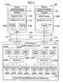
- Fig. 1is a diagram showing a configuration of a SAN system in the present embodiment.
- the present SAN systemincludes a storage device A 120, a server group including a server A 110A and a server B 110B, a SAN 140 for connecting the server group and the storage device to each other, a management server 130, and a LAN 150 for connecting the server group and the storage device to the management server 130.
- Each of the serversmay be a computer in which a program is executed, a terminal device using the function of the computer, or a different one.
- Each of the server group and the storage device Atransmits its performance information to the management server 130 via the LAN 150, and the management server 130 stores the performance information in its internal secondary storage device.
- the server A 110Ais connected to the SAN 140 via an HBA 114.
- the server A 110Aexecutes a volume mount function 111A for mounting a volume provided from the storage device A 120, a business program 112A for conducting business processing by using the mounted volume, and a server performance information collection program 101 for collecting performance information of a server volume.
- the server B 110Bis connected to the SAN 140 via an HBA, and the server B 110B executes a volume mount function, a business program, and a server performance information collection program.
- the SAN and LANare used as example of the networks.
- other networkssuch as NASs (Network Attached Storages) may also be used.
- the storage device A 120is connected to the SAN 140 via a port A 123 and a port B 124. Within the storage device A 120, a volume provisioning function 121 for providing a volume for the SAN side and a storage performance information collection program 102 for collecting performance information of the storage device are executed.
- the server group using the volume provided by the storage device A 120includes only two servers: the server A 110A and the server B 110B.
- the present embodimentcan also be applied to a configuration having more storage devices and more servers.
- the management server 130includes a secondary storage device 161, a main storage device 162, a communication device 163, a CPU 164, a display device 165, a keyboard 166 and a mouse 167. Although not illustrated, the management server 130 also includes functions such as a file system required for a server to recognize data stored in the storage device.
- a performance information repository 103 for preserving performance information of the server group and the storage device A 120is stored in the secondary storage device 161.
- An operating system 168is stored in the main storage device 162.
- a performance information analysis program 104for analyzing performance information stored in the performance information repository 103 and displaying a result of the analysis on the display device 165.
- Fig. 2is a diagram showing the volume provisioning function in the storage device A 120 and the volume mount function in the server group.
- the volume provisioning function 120 in the present embodimentprovides a function of enhancing the usability of physical disk groups in the storage device A 120 by using a configuration of the RAID (Redundant Array of Independent Disks), slicing a RAID group, which is virtual disks having a RAID configuration, in sizes that can be easily used by higher rank servers, and making logical volumes obtained as a result of the slicing usable from the SAN side via a port.
- RAIDRedundant Array of Independent Disks
- the storage device A 120includes eight physical disks, i.e., a physical disk A 240A, a physical disk B 240B, a physical disk C 240C a physical disk D 240D, a physical disk E 240E, a physical disk F 240F, a physical disk G 240G and a physical disk H 240H.
- the volume provisioning function 121creates two RAID groups, i.e., a RAID group A 230A and a RAID group B 230B by using these physical disks.
- the RAID groupis the unit obtained by regarding a plurality of physical disk groups having a RAID configuration as one virtual disk.
- the volume provisioning function 121logically slices the created RAID group, and creates six logical volumes as volumes that can be easily used by higher rank servers.
- the volume provisioning function 121creates a logical volume A 220A, a logical volume B 220B and a logical volume C 220C from a RAID group A 230A, and creates a logical volume D 220D, a logical volume E 220E and a logical volume F 220F from a RAID group B 230B.
- the volume provisioning function 121opens the logical volumes to ports and makes the logical volumes accessible from the SAN 140 side.
- the I/O requestis temporarily converted to an I/O request for a corresponding slice portion within the RAID group A, and in addition it is further converted to an I/O request extending over the physical disk A 240A to the physical disk D 240D, which physically form the RAID group A, by the volume provisioning function 121, and processed.
- the volume mount function 111A in the server A 110Amounts volumes opened to the SAN 140 side from the storage device A 120 into the server A 110A, and makes the volumes usable from the business program 112A.
- a volume mount functionis provided as a part of an operating system.
- the server A 110amounts the two volumes, i.e., the volume A 210A and the volume B 210B from the storage device A 120 and uses them.
- the volume A 210A and the volume B 210Bcorrespond to the logical volume A 220A and the logical volume B 220B in the storage device A 120, respectively.
- the server B 110Bmounts a volume C 210C from the storage device A 120, and uses it.
- the volume C 210Ccorresponds to the logical volume C 220C in the storage device A 120.
- All of the logical volumes A, B and Care logical volumes sliced from the RAID group A 230A. In the present embodiment, therefore, I/O loads of the server A and the server B become loads of the same RAID group A, and it can be said that physical contention might occur between I/Os in the situation.
- Fig. 3is a diagram showing an internal structure of the performance information repository 103 stored in the secondary storage device 161 in the management server 130.
- the performance information repository 103includes four tables.
- a server performance information table 310is a table storing performance information for the volumes in the server group.
- a server storage mapping table 320is a table storing mapping information among the volumes in the servers, the ports in the storage device, the logical volumes and the RAID groups.
- a storage RAID group performance information table 330is a table storing performance information for RAID groups in the storage device.
- a storage port performance information table 340is a table storing performance information for ports in the storage device.
- Fig. 4is a diagram showing a cooperation method between the performance information collection program 101 and the performance information analysis program 104.
- the server performance information collection program 101is operating on the server A 110A and the server B 110B.
- the server performance information collection program 101collects performance information for the volumes on the server, and adds records to the server performance information table 310 and the server storage mapping table 320 on the performance information repository 103.
- the storage performance information collection program 102is operating in the storage device A 120.
- the storage performance information collection program 102collects performance information for the ports and the RAID groups in the storage device, and adds records to the storage RAID group performance information table 330 and the storage port performance information table 340 on the performance information repository 103.
- the performance information analysis program 104is operating on the management server 130. In response to a request from the user, the performance information analysis program 104 acquires and analyzes the performance information data on the performance information repository 103, and displays its result on the display device 165.
- Fig. 5is a diagram showing data items stored in the server performance information table 310 in detail.
- the present tableis a table storing I/O performance information for the volumes on the servers, and it is a table to which records are added by the server performance information collection program 101.
- the present tableincludes a server column 511 and a volume column 512, serving as columns for uniquely identifying servers and volumes.
- the present tableincludes an IOPS (IO per second) column 513, a Read IOPS (IO per second) column 514 and a Write IOPS (IO per second) column 515 respectively representing the number of IO times, the number of read IO times and the number of write IO times per second for respective volumes.
- the present tableincludes an Xfer (Transfer) column 516, a Read Xfer (Transfer) column 517 and a Write Xfer (Transfer) column 518 respectively representing the transfer data quantity, read transfer data quantity and the write data quantity per second for respective volumes.
- the present table 310includes a TS column 519 representing time when the performance information was observed.
- Fig. 6is a diagram showing data items stored in the server storage mapping table 320 in detail.
- the present tableis a table representing each volume in each server corresponds to which logical volume and which RAID group via which port in the storage device, and it is a table to which records are added by the server performance information collection program 101.
- the present tableincludes a server column 611 and a volume column 612, serving as columns for uniquely identifying servers and volumes.
- the present tableincludes a storage column 613, a port column 614, a logical volume column 615, and a RAID group column 616, which represent each volume is using which one of storage devices, ports, and logical volumes and RAID groups.
- the server storage mapping table 320has only the latest mapping information.
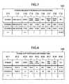
- Fig. 7is a diagram showing data items stored in the storage RAID group performance information table 330 in detail.
- the present tableis a table storing I/O performance information for respective RAID groups in respective storage devices, and it is a table to which records are added by the storage performance information collection program 102.
- the present tableincludes a storage column 711 and an RAID group column 712, serving as columns for uniquely identifying RAID groups on storage devices.
- the present tableincludes an IOPS (IO per second) column 713, a Read IOPS (IO per second) column 714 and a Write IOPS (IO per second) column 715 respectively representing the number of IO times, the number of read IO times and the number of write IO times per second for respective RAID groups.
- the present tableincludes an Xfer (Transfer) column 716, a Read Xfer (Transfer) column 717 and a Write Xfer (Transfer) column 718 respectively representing the transfer data quantity, the read transfer data quantity and the write data quantity per second for respective RAID groups. Finally, the present table includes a TS column 719 representing time when the performance information was observed.
- Fig. 8is a diagram showing data items stored in the storage port performance information table 340 in detail.
- the present tableis a table storing I/O performance information for respective ports in respective storage devices, and it is a table to which records are added by the storage performance information collection program 102.
- the present tableincludes a storage column 811 and a port column 812, serving as columns for uniquely identifying ports on storage devices.
- the present tableincludes an IOPS (IO per second) column 813, a Max IOPS (IO per second) column 814 and a Min IOPS (IO per second) column 815 respectively representing the number of IO times, the maximum number of IO times and the minimum number of IO times per second for respective ports.
- the present tableincludes an Xfer (Transfer) column 816, a Read Xfer (Transfer) column 817 and a Write Xfer (Transfer) column 818 respectively representing the transfer data quantity, the maximum transfer data quantity and the minimum data quantity per second for respective ports.
- the present tableincludes a TS column 819 representing time when the performance information was observed.
- Fig. 9is a diagram showing SCSI inquiry response information.
- SCSI inquiriescan be issued from the server to respective volumes.
- the issued SCSI inquiryis transferred to a storage device via the SAN.
- the storage devicereturns SCSI inquiry response information shown in Fig. 9 to the server side as its response.
- the server performance information collection program 101issues SCSI inquiries to volumes on respective servers, and acquires information of a storage device side of connection destination by utilizing returned SCSI inquiry response information. Furthermore, in the present embodiment, the SCSI inquiry response information holds a storage device name, a port name, a logical volume name and a RAID group name of the connection destination in a connection destination storage column 911, a connection destination port column 912, a connection destination logical volume column 913 and a connection destination RAID group column 914.
- Fig. 10is a flow chart showing processing of the server performance information collection program 101.
- the server performance information collection program 101is a program for acquiring performance information and storage device information of connection destination for all volumes on a server on which the present program operates and adding records to the performance information repository 103.
- step 100initialization processing for repetitively conducting processing for all volumes in the server is conducted.
- the OSis requested to acquire the performance information of the volume and its result is acquired.
- the number of IO times, the number of read IO times and the number of write IO times per second, the transfer data quantity, the read transfer data quantity and the write data quantity per secondare acquired for respective volumes, as an example.
- the performance information of the volume acquired at the step 1002is added to the server performance information table 310 together with a time stamp.
- a SCSI inquiryis issued for the volume and SCSI inquiry information 910 is acquired. Furthermore, information of the storage device, port, logical volume and RAID group that are being utilized by the volume is extracted from the acquired SCSI inquiry information 910.
- connection destination information of the volume acquired at the step 1004is assed to the server storage mapping table 320. If mapping information of the volume already exists, it is deleted and then addition is conducted.
- step 1006it is checked whether the volume is the last volume on the server. If the volume is the last volume, the processing is finished. If there are still remaining volumes, the processing returns to the step 1002.
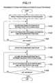
- Fig. 11is a flow chart showing processing of the storage performance information collection program 101.
- the storage performance information collection program 101is a program for acquiring performance information for all ports and RAID groups on the storage device on which the present program operates, and adding records to the performance information repository 103.
- step 1101initialization processing for repetitively conducting processing for all ports in the storage device is conducted.
- the storage deviceis requested to acquire the performance information of the port and its result is acquired.
- the number of IO times, the maximum number of IO times and the minimum number of IO times per second, the transfer data quantity, the maximum transfer data quantity and the minimum data quantity per secondare acquired for respective ports, as an example.
- the performance information of the port acquired at the step 1102is added to the storage port performance information table 340 together with a time stamp.
- step 1104it is checked whether the port is the last port on the storage device. If the port is the last port, the processing proceeds to step 1105. If there is a remaining port, the processing returns to the step 1102.
- step 1105initialization processing for repetitively conducting processing for all RAID groups in the storage device is conducted.
- the storage deviceis requested to acquire the performance information of the RAID group and its result is acquired.
- the number of IO times, the number of read IO times and the number of write IO times per second, the transfer data quantity, the read transfer data quantity and the write data quantity per secondare acquired for respective RAID groups, as an example.
- the performance information of the RAID group acquired at the step 1106is added to the storage RAID group performance information table 330 together with a time stamp.
- step 1108it is checked whether the RAID group is the last RAID group on the storage device. If the RAID group is the last RAID group, the processing is finished. If there is a remaining RAID group, the processing returns to the step 1106.
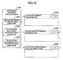
- Fig. 12is a diagram showing an internal structure of the performance information analysis program 104 and schematically showing a view that is output by the present program.
- the performance information analysis program 104includes three internal subprograms, i.e., a storage performance information display subprogram 1201, a related server performance information display subprogram 1202 and a related server performance history information display subprogram 1203.
- the storage performance information display subprogram 1201is a program for providing the user with performance information of ports and RAID groups in the storage device by displaying a storage performance information view 1210.
- the related server performance information display subprogram 1202is a program for narrowing down volumes to volumes on the server side utilizing ports or RAID group resources of a certain specific storage side and displaying performance information of a plurality of server side volumes by displaying a related server performance information view 1220.
- the related server performance information view 1220is started from the storage performance information view 1210 according to a user's request. By watching the related server performance information view 1220, it becomes easy for the user to discriminate a server that burdens a load on a specific resource in the storage device. And by perusing the performance information of the server group at a stroke, a server that especially burdens load on the resource can be discriminated.
- the related server performance history information display subprogram 1203is a program for displaying performance history information of a server group using a specific resource in the storage device in a time series form in the order of time when performance information was observed by displaying a related server performance history information view 1230.
- the related server performance history information view 1230is started from the related server performance information view 1220 according to a user's request.
- Fig. 13is a diagram showing an embodiment of the storage performance information view 1210.
- the present viewincludes a storage object selection region 1310, a performance display date and hour input region 1320, a selected object performance information display region 1330 and a related server performance display button 1340.
- a storage device and resources within the storage deviceare displayed in a tree form in the storage performance information view 1210.
- a storage device A node 1311is displayed as a parent node of the tree
- RAID groups and portsare displayed as child nodes like a RAID group A node 1312, a RAID group B node 1313, a port A node 1314 and a port B node 1315.
- the usercan select one of the child nodes in the present storage object selection region, and performance information concerning the selected object is displayed in the selected object performance information display region 1330.
- kinds of resources within the storage to be subjected to the performance analysisare two kinds, i.e., the RAID group and port.
- the present embodimentcan also be applied to other resources such as cache memories in the storage device, and the application is not limited.
- the performance display date and hour input region 1320is a region for the user to input the time when the performance information to be displayed. Performance information at the date and hour that has been input to the region is retrieved and displayed in the selected object performance information display region 1330.
- the programmay previously specify that the current time should be displayed, or performance information in a predetermined interval may be displayed in time series order according to data accepted by the user. Other specification is also possible.
- the selected object performance information display region 1330is a region for displaying performance information concerning an object selected in the storage object selection region 1310 as regards the date and hour that has been input in the performance display date and hour input region 1320.
- Fig. 13it is supposed that the RAID group A node 1312 has been selected in the storage object selection region 1310 and "10 a.m., July 19, 2003" has been input as the performance display date and hour. Therefore, performance information of the RAID group A at 10 a.m., July 19, 2003 is displayed in the selected object performance information display region 1330.
- the selected resource namei.e., "RAID group A” is displayed in a selected object display region 1337
- the performance information of the RAID group A at 10 a.m., July 19, 2003is displayed in an IOPS (IO per second) column 1331, a Read IOPS (IO per second) column 1332, a Write IOPS (IO per second) column 1333, an Xfer (Transfer) column 1334, a Read Xfer (Transfer) column 1335 and a Write Xfer (Transfer) column 1336.
- the related server performance display button 1340is a button for requesting the display of the related server performance information view 1220. By pressing the present button, it is possible to display the related server performance information view 1220 for displaying the performance information of a volume on the server side utilizing an object selected in the storage object selection region 1310. On the inside, the present button starts the related server performance information display subprogram 1202.
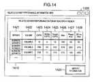
- Fig. 14is a diagram showing an embodiment of the related server performance information view 1220.
- the present viewis a view that displays a list of servers and volumes utilizing a specific RAID group or port, and their performance information. By watching the present view, the user can discriminate a server and a volume that burden the load on a specific RAID group or port.
- the related server performance information view 1220includes a related server performance information display region 1410 and a history information display button 1420.
- the related server performance information display region 1410is a region for displaying a list of related servers and volumes and their performance information.
- the related server performance information display region 1410includes a server column 1421 and a volume column 1422 for specifying a server and a volume that utilize the RAID group or port.
- an IOPS (IO per second) column 1423, a Write IOPS (IO per second) column 1424, a Read IOPS (IO per second) column 1425, an Xfer (Transfer) column 1426, a Read Xfer (Transfer) column 1427 and a Write Xfer (Transfer) column 1428are displayed as the performance information of the volume in the related server performance information display region 1410.
- the history information display button 1420is a button for requesting the display of the related server performance history information view 1230. By pressing the present button, the related server performance history information view 1230 for historically displaying the performance information of the related server group can be displayed. On the inside, the present button starts the related server performance history information display subprogram 1203.
- Fig. 15is a diagram showing an embodiment of the related server performance history information view 1230.
- the present viewhistorically displays the performance information of the related server group.
- the present viewincludes a related server performance history information display region 1510.
- Historical performance information of the related serveris displayed in the related server performance history information display region 1510 by broken line graphs as shown in Fig. 15.
- the abscissa of the graphindicates time, and the ordinate of the graph indicates performance, as an example.
- Performance history data for the volume A in the server A and performance history data for the volume C in the server Bare displayed by superposition of broken line graphs, and a server name and a volume name are added to each of the broken line graphs.
- thisis an example, and performance information of devices other than servers may also be displayed.
- performance informationmay be displayed by using one view every logical volume.
- the performance informationmay be displayed by using a window every RAID group.
- other display methodsmay also be used.
- Information data of devices sharing a storage device specified by the usermay be superposed and displayed by using graphs having the same coordinate axes.
- the performance information of the specified storage device and performance information data of three devices having the highest loads among devices utilizing the specified storage devicemay be displayed so as to be associated with each other.
- a different display methodmay also be used.
- the performance information datamay be displayed in one window so as to be superposed in the order of increasing value, the performance information data may be displayed in one window in accordance with a predetermined order, or a plurality of windows may be displayed side by side in the horizontal direction or the vertical direction in association.
- performance data of the devices and computersare not shown singly, but they are displayed in association with performance information of related devices on a path between a server and a storage device and performance information of devices sharing the storage device. As a result, it becomes easy to discriminate a part that becomes a performance bottleneck even in a complicated system environment.
- Fig. 16is a flow chart showing processing of the storage performance information display subprogram 1201.
- the present programis a program for displaying the storage performance information view 1210.
- Steps 1601 to 1603are processing for drawing the storage object selection region 1310.
- Processing ranging from the step 1604 to end processingis processing for drawing the selected object performance information display region 1330.
- the storage RAID group performance information table 330is scanned, and a list of pairs of all RAID groups and storage devices to which the RAID groups belong is acquired.
- the storage port performance information table 340is scanned, and a list of pairs of all ports and storage devices to which the ports belong is acquired.
- step 1603all storage devices, RAID groups and ports are drawn in the storage object selection region 1310 on the basis of the list of RAID groups paired with storage devices and the list of ports paired with storage devices acquired respectively at the steps 1601 and 1602.
- step 1604date and hour information that has been input in the performance display date and hour input region 1320 is acquired.
- a name of an object selected in the storage object selection region 1310is acquired. For example, specification of an identifier of an RAID group, a port name, and a name and an identifier of a storage related device is accepted.
- step 1607on the basis of the name of the storage object acquired at the step 1605, it is determined whether the object is an RAID group or a port. If the object is a RAID group, the processing proceeds to a step 1608. If the object is a port, the processing proceeds to step 1610.
- the storage RAID group performance information table 330is searched by using the object name acquired at the step 1605 and the date and hour acquired at the step 1604 as a key, and performance information of the selected RAID group at the specified date and hour is acquired.
- step 1609performance information of the RAID group acquired at the step 1608 is drawn in the selected object performance information display region 1330.
- the storage port performance information table 340is searched by using the object name acquired at the step 1605 and the date and hour acquired at the step 1604 as a key, and performance information of the selected port at the specified date and hour is acquired.
- performance information of the port acquired at the step 1610is drawn in the selected object performance information display region 1330.
- Fig. 17is a flow chart showing processing of the related server performance information display subprogram 1202.
- the present programis a program that is executed to draw the related server performance information view 1220 when the user has pressed the related server performance display button 1340 on the storage performance information view 1210.
- step 1701date and hour information that has been input in the performance display date and hour input region 1320 is acquired.
- a name of an object selected in the storage object selection region 1310is acquired.
- step 1703on the basis of the name of the storage object acquired at the step 1702, it is determined whether the object is an RAID group or a port. If the object is a RAID group, the processing proceeds to a step 1704. If the object is a port, the processing proceeds to step 1705.
- the server storage mapping table 320is searched by using the object name acquired at the step 1702 as a key for the RAID group column, and a list of volumes of servers utilizing the RAID group is acquired.
- the server storage mapping table 320is searched by using the object name acquired at the step 1702 as a key for the port column, and a list of volumes of servers utilizing the port is acquired.
- the server performance information table 310is searched by using the date and hour acquired at the step 1701 and the volume list of servers acquired at the step 1704 or 1705 as a key, and performance information of the volume group of the server side utilizing the RAID group or the port is acquired.
- step 1707performance information of the related server acquired at the step 1706 is drawn in the related server performance information display region 1410.
- Fig. 18is a flow chart showing processing of the related server performance history information display subprogram 1203.
- the present programis a program that is executed to draw the related server performance history information view 1230 when the user has pressed the history information display button 1420 on the related server performance information view 1220.
- step 1801a list of volumes of the server side displayed in the related server performance information region 1410 is acquired.
- the server performance information table 310is searched by using the volume list of the server side acquired at the step 1801 as a key, and historical performance data of the volume group is acquired.
- the related server performance history information view 1230is created, and historical performance data of related volumes acquired at the step 1802 are drawn in the related server performance history information display region 1510.
- the above-described processing and display transitionare an example, and different view transition may be conducted.
- load information of a plurality of servers utilizing the RAID group Amay be displayed in a form of superposed graphs (for example, as shown in Fig. 15).
- a portmay be specified and load information of a server utilizing the port may be displayed on the basis of the specified port information.
- route information utilizing the portwith a storage device on the route (for example, in a form such as "server - volume name - switch (I/O port) - logical volume - RAID group - physical disk"), and display information relating to each of the storage devices. Different display may also be conducted.
- the server degraded in performanceAs a reference point and display performance information of ports utilized by the server and information of servers utilizing the ports. Or it is also possible to check logical volumes and RAID groups utilized by the server, and display performance information of other servers sharing and utilizing the logical volumes and RAID groups.
- a specific resource within the storage deviceis regarded as the starting point, and performance index values of the server group (or various devices) that burdens the load on the resource are displayed at a stroke.
- performance index values of the server group (or various devices) that burdens the load on the resourceare displayed at a stroke.
- performance values of devices that burden the load on a storage deviceare displayed in association. As a result, it is possible to easily discriminate a server group that causes I/O contention on a resource in the storage device, or a part that becomes a bottleneck in performance.
Landscapes
- Engineering & Computer Science (AREA)
- Theoretical Computer Science (AREA)
- General Engineering & Computer Science (AREA)
- Physics & Mathematics (AREA)
- General Physics & Mathematics (AREA)
- Computer Hardware Design (AREA)
- Quality & Reliability (AREA)
- Human Computer Interaction (AREA)
- Computing Systems (AREA)
- Information Retrieval, Db Structures And Fs Structures Therefor (AREA)
- Debugging And Monitoring (AREA)
- Digital Computer Display Output (AREA)
Abstract
Description
- The present invention relates to a system for displaying/analyzing performance information of servers and storage devices.
- In recent years, configurations in which a plurality of servers share a single storage device have increased because of the development of the SAN (Storage Area Network) technique. The reason why such configurations are increasing is that the localization of the operational business such as backup and fault control is facilitated and the operation management cost can be compressed.
- On the other hand, however, since a plurality of servers share a single storage device, volume assignment and storage performance management become complicated. A method for simplifying the volume assignment in the SAN environment is disclosed in
US 2003/0005119A1 . - In computer systems, the storage device is a low speed storage medium as compared with caches and memories in the CPU. Often, therefore, the storage device becomes a bottleneck for the whole system. Therefore, it is important to acquire various performance index values in the construction phase and the operation phase and make an analysis to determine whether predetermined performance values have been obtained so that the storage device may exhibit as high performance as possible.
- In a configuration in which a plurality of servers share and use a single storage device, I/O transactions from a plurality of servers overlap on a specific resource within the storage device and consequently serious performance degradation is caused in some cases.
- As an example, I/O loads from a plurality of servers concentrate on a specific physical disk group within a storage device, and the I/O performance seen from the server side is not sufficiently exhibited due to the I/O contention.
- Owing to a tool provided by the storage device, the I/O quantity processed by a specific resource within the storage device can be perused/analyzed. In this method, however, it is difficult to discriminate the cause of an I/O contention performance problem caused by setting on the outside of the storage device, i.e., specifically a server group that burdens an I/O load on a specific resource within the storage device or a portion that becomes a bottleneck of the performance.
- The present invention may provide a method for solving the above-described problem and facilitating the discrimination of a server group that is causing I/0 contention on a resource in a storage device and a portion that has become a bottleneck in performance.
- In accordance with the present invention, a method according to
claim 1 is provided. - The present invention may provide a performance information display method using a computer preferably includes the steps, in the computer, of reading out information data of a storage device previously stored in a storage device and information data of a plurality of devices utilizing the storage device, displaying an identifier of the storage device and identifiers of a plurality of devices utilizing the storage device on a screen on the basis of the information data read out, accepting a command to select the displayed identifier of the storage device, and displaying performance information data of the devices utilizing the selected storage device in association on the basis of the accepted command and the information data read out.
- The present invention may provide a method of taking a specific resource within the storage device as a starting point and displaying at a stroke performance index values of a server group that burdens the load on the resource. Specifically, a performance management tool preferably collects mapping information between the storage device and the servers and performance information of the server group. If there is a command from the user, the performance management tool searches the mapping information between the storage device and the servers for the server group utilizing a specific resource within the storage device, and creates a report of I/O contention narrowed down to the performance data of the server group.
- Other objects, features and advantages of the invention will become apparent from the following description of the embodiments of the invention taken in conjunction with the accompanying drawings.
- Fig. 1 is a diagram showing a configuration of a SAN system in an embodiment;
- Fig. 2 is a diagram showing a volume provisioning function of a storage device and a volume mount function of a server;
- Fig. 3 is a diagram showing an internal structure of a performance information repository;
- Fig. 4 is a diagram showing a cooperation method between a performance information collection program and a performance information analysis program;
- Fig. 5 is a diagram showing data items stored in a server performance information table;
- Fig. 6 is a diagram showing data items stored in a server storage mapping table;
- Fig. 7 is a diagram showing data items stored in a storage RAID group performance information table;
- Fig. 8 is a diagram showing data items stored in a storage port performance information table;
- Fig. 9 is a diagram showing SCSI inquiry response information;
- Fig. 10 is a flow chart showing processing of a server performance information collection program;
- Fig. 11 is a flow chart showing processing of a storage performance information collection program;
- Fig. 12 is a diagram showing an internal structure of a performance information analysis program and schematic views that are output by the performance information analysis program;
- Fig. 13 is a diagram showing an embodiment of a storage performance information view;
- Fig. 14 is a diagram showing an embodiment of a related server performance information view;
- Fig. 15 is a diagram showing an embodiment of a related server performance history information view;
- Fig. 16 is a flow chart showing processing of a storage performance information display subprogram;
- Fig. 17 is a flow chart showing processing of a related server performance information display subprogram; and
- Fig. 18 is a flow chart showing processing of a related server performance history information display subprogram.
- Hereafter, an embodiment of the present invention in a SAN system in which a plurality of servers share a storage device will be described.
- Examples of the SAN system in the embodiment described hereafter are simplified as compared with the ordinary SAN system because functions and details that are not necessary for description of the present embodiment are omitted. However, the application range of the present embodiment is not limited thereby.
- Fig. 1 is a diagram showing a configuration of a SAN system in the present embodiment. The present SAN system includes a storage device A 120, a server group including a
server A 110A and aserver B 110B, a SAN 140 for connecting the server group and the storage device to each other, amanagement server 130, and aLAN 150 for connecting the server group and the storage device to themanagement server 130. Each of the servers may be a computer in which a program is executed, a terminal device using the function of the computer, or a different one. - Each of the server group and the storage device A transmits its performance information to the
management server 130 via theLAN 150, and themanagement server 130 stores the performance information in its internal secondary storage device. - The server A 110A is connected to the SAN 140 via an HBA 114. The server A 110A executes a
volume mount function 111A for mounting a volume provided from thestorage device A 120, abusiness program 112A for conducting business processing by using the mounted volume, and a server performanceinformation collection program 101 for collecting performance information of a server volume. - In the same way as the server A, the
server B 110B is connected to the SAN 140 via an HBA, and theserver B 110B executes a volume mount function, a business program, and a server performance information collection program. Here, the SAN and LAN are used as example of the networks. However, other networks such as NASs (Network Attached Storages) may also be used. - The storage device A 120 is connected to the SAN 140 via a
port A 123 and aport B 124. Within the storage device A 120, avolume provisioning function 121 for providing a volume for the SAN side and a storage performanceinformation collection program 102 for collecting performance information of the storage device are executed. - In the present embodiment, it is supposed for brevity that one storage device is used, and the server group using the volume provided by the storage device A 120 includes only two servers: the
server A 110A and theserver B 110B. However, the present embodiment can also be applied to a configuration having more storage devices and more servers. - The
management server 130 includes asecondary storage device 161, amain storage device 162, acommunication device 163, aCPU 164, adisplay device 165, akeyboard 166 and amouse 167. Although not illustrated, themanagement server 130 also includes functions such as a file system required for a server to recognize data stored in the storage device. - A
performance information repository 103 for preserving performance information of the server group and the storage device A 120 is stored in thesecondary storage device 161. Anoperating system 168 is stored in themain storage device 162. Within theoperating system 168, a performanceinformation analysis program 104 for analyzing performance information stored in theperformance information repository 103 and displaying a result of the analysis on thedisplay device 165. - Fig. 2 is a diagram showing the volume provisioning function in the
storage device A 120 and the volume mount function in the server group. - First, the volume provisioning function will now be described. The
volume provisioning function 120 in the present embodiment provides a function of enhancing the usability of physical disk groups in the storage device A 120 by using a configuration of the RAID (Redundant Array of Independent Disks), slicing a RAID group, which is virtual disks having a RAID configuration, in sizes that can be easily used by higher rank servers, and making logical volumes obtained as a result of the slicing usable from the SAN side via a port. By thus combining a plurality of disks, it becomes possible to make the disk access fast and enhance the fault resistance against failures of disks. - Specifically, the
storage device A 120 includes eight physical disks, i.e., a physical disk A 240A, aphysical disk B 240B, aphysical disk C 240C aphysical disk D 240D, aphysical disk E 240E, aphysical disk F 240F, aphysical disk G 240G and aphysical disk H 240H. In the present embodiment, thevolume provisioning function 121 creates two RAID groups, i.e., a RAID group A 230A and aRAID group B 230B by using these physical disks. - The RAID group is the unit obtained by regarding a plurality of physical disk groups having a RAID configuration as one virtual disk.
- Furthermore, in the present embodiment, the
volume provisioning function 121 logically slices the created RAID group, and creates six logical volumes as volumes that can be easily used by higher rank servers. In other words, thevolume provisioning function 121 creates alogical volume A 220A, alogical volume B 220B and alogical volume C 220C from a RAID group A 230A, and creates alogical volume D 220D, alogical volume E 220E and alogical volume F 220F from aRAID group B 230B. Furthermore, thevolume provisioning function 121 opens the logical volumes to ports and makes the logical volumes accessible from theSAN 140 side. - For example, if an I/O request is issued to the logical volume A by a server via the port A, the I/O request is temporarily converted to an I/O request for a corresponding slice portion within the RAID group A, and in addition it is further converted to an I/O request extending over the physical disk A 240A to the
physical disk D 240D, which physically form the RAID group A, by thevolume provisioning function 121, and processed. - The volume mount function will now be described. The
volume mount function 111A in theserver A 110A mounts volumes opened to theSAN 140 side from thestorage device A 120 into theserver A 110A, and makes the volumes usable from thebusiness program 112A. The same holds true for theserver B 110B as well. Typically, such a volume mount function is provided as a part of an operating system. - Finally, correlation between server side volumes and storage side volumes in the present embodiment will now be described. In the present embodiment, the server A 110a mounts the two volumes, i.e., the
volume A 210A and thevolume B 210B from thestorage device A 120 and uses them. Thevolume A 210A and thevolume B 210B correspond to thelogical volume A 220A and thelogical volume B 220B in thestorage device A 120, respectively. - The
server B 110B mounts avolume C 210C from thestorage device A 120, and uses it. Thevolume C 210C corresponds to thelogical volume C 220C in thestorage device A 120. All of the logical volumes A, B and C are logical volumes sliced from the RAID group A 230A. In the present embodiment, therefore, I/O loads of the server A and the server B become loads of the same RAID group A, and it can be said that physical contention might occur between I/Os in the situation. - Fig. 3 is a diagram showing an internal structure of the
performance information repository 103 stored in thesecondary storage device 161 in themanagement server 130. Theperformance information repository 103 includes four tables. A server performance information table 310 is a table storing performance information for the volumes in the server group. A server storage mapping table 320 is a table storing mapping information among the volumes in the servers, the ports in the storage device, the logical volumes and the RAID groups. A storage RAID group performance information table 330 is a table storing performance information for RAID groups in the storage device. A storage port performance information table 340 is a table storing performance information for ports in the storage device. - Fig. 4 is a diagram showing a cooperation method between the performance
information collection program 101 and the performanceinformation analysis program 104. - As described earlier, the server performance
information collection program 101 is operating on theserver A 110A and theserver B 110B. The server performanceinformation collection program 101 collects performance information for the volumes on the server, and adds records to the server performance information table 310 and the server storage mapping table 320 on theperformance information repository 103. - The storage performance
information collection program 102 is operating in thestorage device A 120. The storage performanceinformation collection program 102 collects performance information for the ports and the RAID groups in the storage device, and adds records to the storage RAID group performance information table 330 and the storage port performance information table 340 on theperformance information repository 103. - The performance
information analysis program 104 is operating on themanagement server 130. In response to a request from the user, the performanceinformation analysis program 104 acquires and analyzes the performance information data on theperformance information repository 103, and displays its result on thedisplay device 165. - Fig. 5 is a diagram showing data items stored in the server performance information table 310 in detail. The present table is a table storing I/O performance information for the volumes on the servers, and it is a table to which records are added by the server performance
information collection program 101. In the present embodiment, the present table includes aserver column 511 and avolume column 512, serving as columns for uniquely identifying servers and volumes. - The present table includes an IOPS (IO per second)
column 513, a Read IOPS (IO per second)column 514 and a Write IOPS (IO per second)column 515 respectively representing the number of IO times, the number of read IO times and the number of write IO times per second for respective volumes. - The present table includes an Xfer (Transfer)
column 516, a Read Xfer (Transfer)column 517 and a Write Xfer (Transfer)column 518 respectively representing the transfer data quantity, read transfer data quantity and the write data quantity per second for respective volumes. Finally, the present table 310 includes aTS column 519 representing time when the performance information was observed. - Fig. 6 is a diagram showing data items stored in the server storage mapping table 320 in detail. The present table is a table representing each volume in each server corresponds to which logical volume and which RAID group via which port in the storage device, and it is a table to which records are added by the server performance
information collection program 101. - In the present embodiment, the present table includes a
server column 611 and avolume column 612, serving as columns for uniquely identifying servers and volumes. The present table includes astorage column 613, aport column 614, alogical volume column 615, and aRAID group column 616, which represent each volume is using which one of storage devices, ports, and logical volumes and RAID groups. - In the present embodiment, it is supposed that the server storage mapping table 320 has only the latest mapping information. However, it is also possible to add a mapping information acquisition time column to the present table to provide the present table with past history information of the mapping information, and thereby create a report having related server groups narrowed down on the basis of the past mapping information.
- Fig. 7 is a diagram showing data items stored in the storage RAID group performance information table 330 in detail. The present table is a table storing I/O performance information for respective RAID groups in respective storage devices, and it is a table to which records are added by the storage performance
information collection program 102. In the present embodiment, the present table includes astorage column 711 and anRAID group column 712, serving as columns for uniquely identifying RAID groups on storage devices. The present table includes an IOPS (IO per second)column 713, a Read IOPS (IO per second)column 714 and a Write IOPS (IO per second)column 715 respectively representing the number of IO times, the number of read IO times and the number of write IO times per second for respective RAID groups. - The present table includes an Xfer (Transfer)
column 716, a Read Xfer (Transfer)column 717 and a Write Xfer (Transfer)column 718 respectively representing the transfer data quantity, the read transfer data quantity and the write data quantity per second for respective RAID groups. Finally, the present table includes aTS column 719 representing time when the performance information was observed. - Fig. 8 is a diagram showing data items stored in the storage port performance information table 340 in detail. The present table is a table storing I/O performance information for respective ports in respective storage devices, and it is a table to which records are added by the storage performance
information collection program 102. - In the present embodiment, the present table includes a
storage column 811 and aport column 812, serving as columns for uniquely identifying ports on storage devices. The present table includes an IOPS (IO per second)column 813, a Max IOPS (IO per second)column 814 and a Min IOPS (IO per second)column 815 respectively representing the number of IO times, the maximum number of IO times and the minimum number of IO times per second for respective ports. The present table includes an Xfer (Transfer)column 816, a Read Xfer (Transfer)column 817 and a Write Xfer (Transfer)column 818 respectively representing the transfer data quantity, the maximum transfer data quantity and the minimum data quantity per second for respective ports. Finally, the present table includes aTS column 819 representing time when the performance information was observed. - Fig. 9 is a diagram showing SCSI inquiry response information. SCSI inquiries can be issued from the server to respective volumes. The issued SCSI inquiry is transferred to a storage device via the SAN. The storage device returns SCSI inquiry response information shown in Fig. 9 to the server side as its response.
- In the present embodiment, the server performance
information collection program 101 issues SCSI inquiries to volumes on respective servers, and acquires information of a storage device side of connection destination by utilizing returned SCSI inquiry response information. Furthermore, in the present embodiment, the SCSI inquiry response information holds a storage device name, a port name, a logical volume name and a RAID group name of the connection destination in a connectiondestination storage column 911, a connectiondestination port column 912, a connection destinationlogical volume column 913 and a connection destinationRAID group column 914. - Here, an example in which various kinds of information are collected by using an SCSI command is shown as an example. However, information may be collected by using a method other than this.
- Fig. 10 is a flow chart showing processing of the server performance
information collection program 101. The server performanceinformation collection program 101 is a program for acquiring performance information and storage device information of connection destination for all volumes on a server on which the present program operates and adding records to theperformance information repository 103. - At
step 1001, initialization processing for repetitively conducting processing for all volumes in the server is conducted. - At
step 1002, the OS is requested to acquire the performance information of the volume and its result is acquired. In the present embodiment, the number of IO times, the number of read IO times and the number of write IO times per second, the transfer data quantity, the read transfer data quantity and the write data quantity per second are acquired for respective volumes, as an example. - At
step 1003, the performance information of the volume acquired at thestep 1002 is added to the server performance information table 310 together with a time stamp. - At
step 1004, a SCSI inquiry is issued for the volume andSCSI inquiry information 910 is acquired. Furthermore, information of the storage device, port, logical volume and RAID group that are being utilized by the volume is extracted from the acquiredSCSI inquiry information 910. - At
step 1005, connection destination information of the volume acquired at thestep 1004 is assed to the server storage mapping table 320. If mapping information of the volume already exists, it is deleted and then addition is conducted. - At
step 1006, it is checked whether the volume is the last volume on the server. If the volume is the last volume, the processing is finished. If there are still remaining volumes, the processing returns to thestep 1002. - Fig. 11 is a flow chart showing processing of the storage performance
information collection program 101. The storage performanceinformation collection program 101 is a program for acquiring performance information for all ports and RAID groups on the storage device on which the present program operates, and adding records to theperformance information repository 103. - At
step 1101, initialization processing for repetitively conducting processing for all ports in the storage device is conducted. - At
step 1102, the storage device is requested to acquire the performance information of the port and its result is acquired. In the present embodiment, the number of IO times, the maximum number of IO times and the minimum number of IO times per second, the transfer data quantity, the maximum transfer data quantity and the minimum data quantity per second are acquired for respective ports, as an example. - At
step 1103, the performance information of the port acquired at thestep 1102 is added to the storage port performance information table 340 together with a time stamp. - At
step 1104, it is checked whether the port is the last port on the storage device. If the port is the last port, the processing proceeds to step 1105. If there is a remaining port, the processing returns to thestep 1102. - At
step 1105, initialization processing for repetitively conducting processing for all RAID groups in the storage device is conducted. - At
step 1106, the storage device is requested to acquire the performance information of the RAID group and its result is acquired. In the present embodiment, the number of IO times, the number of read IO times and the number of write IO times per second, the transfer data quantity, the read transfer data quantity and the write data quantity per second are acquired for respective RAID groups, as an example. - At
step 1107, the performance information of the RAID group acquired at thestep 1106 is added to the storage RAID group performance information table 330 together with a time stamp. - At
step 1108, it is checked whether the RAID group is the last RAID group on the storage device. If the RAID group is the last RAID group, the processing is finished. If there is a remaining RAID group, the processing returns to thestep 1106. - Fig. 12 is a diagram showing an internal structure of the performance
information analysis program 104 and schematically showing a view that is output by the present program. - The performance
information analysis program 104 includes three internal subprograms, i.e., a storage performanceinformation display subprogram 1201, a related server performanceinformation display subprogram 1202 and a related server performance historyinformation display subprogram 1203. - The storage performance
information display subprogram 1201 is a program for providing the user with performance information of ports and RAID groups in the storage device by displaying a storageperformance information view 1210. - The related server performance
information display subprogram 1202 is a program for narrowing down volumes to volumes on the server side utilizing ports or RAID group resources of a certain specific storage side and displaying performance information of a plurality of server side volumes by displaying a related serverperformance information view 1220. - The related server
performance information view 1220 is started from the storageperformance information view 1210 according to a user's request. By watching the related serverperformance information view 1220, it becomes easy for the user to discriminate a server that burdens a load on a specific resource in the storage device. And by perusing the performance information of the server group at a stroke, a server that especially burdens load on the resource can be discriminated. - The related server performance history
information display subprogram 1203 is a program for displaying performance history information of a server group using a specific resource in the storage device in a time series form in the order of time when performance information was observed by displaying a related server performancehistory information view 1230. The related server performancehistory information view 1230 is started from the related serverperformance information view 1220 according to a user's request. - Fig. 13 is a diagram showing an embodiment of the storage
performance information view 1210. The present view includes a storageobject selection region 1310, a performance display date andhour input region 1320, a selected object performanceinformation display region 1330 and a related serverperformance display button 1340. - In the present embodiment, a storage device and resources within the storage device are displayed in a tree form in the storage
performance information view 1210. Specifically, in Fig. 13, a storagedevice A node 1311 is displayed as a parent node of the tree, and RAID groups and ports are displayed as child nodes like a RAIDgroup A node 1312, a RAIDgroup B node 1313, a port A node 1314 and aport B node 1315. The user can select one of the child nodes in the present storage object selection region, and performance information concerning the selected object is displayed in the selected object performanceinformation display region 1330. - In the present embodiment, kinds of resources within the storage to be subjected to the performance analysis are two kinds, i.e., the RAID group and port. However, the present embodiment can also be applied to other resources such as cache memories in the storage device, and the application is not limited.
- The performance display date and
hour input region 1320 is a region for the user to input the time when the performance information to be displayed. Performance information at the date and hour that has been input to the region is retrieved and displayed in the selected object performanceinformation display region 1330. As for the specification of the date and hour for displaying the performance information, the program may previously specify that the current time should be displayed, or performance information in a predetermined interval may be displayed in time series order according to data accepted by the user. Other specification is also possible. - The selected object performance
information display region 1330 is a region for displaying performance information concerning an object selected in the storageobject selection region 1310 as regards the date and hour that has been input in the performance display date andhour input region 1320. - In Fig. 13, it is supposed that the RAID
group A node 1312 has been selected in the storageobject selection region 1310 and "10 a.m., July 19, 2003" has been input as the performance display date and hour. Therefore, performance information of the RAID group A at 10 a.m., July 19, 2003 is displayed in the selected object performanceinformation display region 1330. Specifically, the selected resource name, i.e., "RAID group A" is displayed in a selectedobject display region 1337, and the performance information of the RAID group A at 10 a.m., July 19, 2003 is displayed in an IOPS (IO per second)column 1331, a Read IOPS (IO per second)column 1332, a Write IOPS (IO per second)column 1333, an Xfer (Transfer)column 1334, a Read Xfer (Transfer)column 1335 and a Write Xfer (Transfer)column 1336. - The related server
performance display button 1340 is a button for requesting the display of the related serverperformance information view 1220. By pressing the present button, it is possible to display the related serverperformance information view 1220 for displaying the performance information of a volume on the server side utilizing an object selected in the storageobject selection region 1310. On the inside, the present button starts the related server performanceinformation display subprogram 1202. - Fig. 14 is a diagram showing an embodiment of the related server
performance information view 1220. The present view is a view that displays a list of servers and volumes utilizing a specific RAID group or port, and their performance information. By watching the present view, the user can discriminate a server and a volume that burden the load on a specific RAID group or port. - The related server
performance information view 1220 includes a related server performanceinformation display region 1410 and a historyinformation display button 1420. - The related server performance
information display region 1410 is a region for displaying a list of related servers and volumes and their performance information. In the present embodiment, the related server performanceinformation display region 1410 includes aserver column 1421 and avolume column 1422 for specifying a server and a volume that utilize the RAID group or port. Furthermore, in the present embodiment, an IOPS (IO per second)column 1423, a Write IOPS (IO per second)column 1424, a Read IOPS (IO per second)column 1425, an Xfer (Transfer)column 1426, a Read Xfer (Transfer)column 1427 and a Write Xfer (Transfer)column 1428 are displayed as the performance information of the volume in the related server performanceinformation display region 1410. - The history
information display button 1420 is a button for requesting the display of the related server performancehistory information view 1230. By pressing the present button, the related server performancehistory information view 1230 for historically displaying the performance information of the related server group can be displayed. On the inside, the present button starts the related server performance historyinformation display subprogram 1203. - Fig. 15 is a diagram showing an embodiment of the related server performance
history information view 1230. The present view historically displays the performance information of the related server group. The present view includes a related server performance historyinformation display region 1510. Historical performance information of the related server is displayed in the related server performance historyinformation display region 1510 by broken line graphs as shown in Fig. 15. - In Fig. 15, the abscissa of the graph indicates time, and the ordinate of the graph indicates performance, as an example. Performance history data for the volume A in the server A and performance history data for the volume C in the server B are displayed by superposition of broken line graphs, and a server name and a volume name are added to each of the broken line graphs. However, this is an example, and performance information of devices other than servers may also be displayed.
- For example, performance information may be displayed by using one view every logical volume. In the case where volumes recognized by respective servers utilize the same RAID group, the performance information may be displayed by using a window every RAID group. Or other display methods may also be used.
- It is also possible to partition one window into a plurality of parts and display various devices in a tree structure on a left-hand part of the window as represented by 1310 in Fig. 13. When the user has selected one of components in the tree structure shown in 1310, performance history information display of related devices (for example, Fig. 15) may be conducted on a right-hand part of the window on the basis of the user's selection.
- Information data of devices sharing a storage device specified by the user may be superposed and displayed by using graphs having the same coordinate axes. The performance information of the specified storage device and performance information data of three devices having the highest loads among devices utilizing the specified storage device may be displayed so as to be associated with each other. A different display method may also be used. When displaying a plurality of performance information data, the performance information data may be displayed in one window so as to be superposed in the order of increasing value, the performance information data may be displayed in one window in accordance with a predetermined order, or a plurality of windows may be displayed side by side in the horizontal direction or the vertical direction in association.
- Thus, performance data of the devices and computers are not shown singly, but they are displayed in association with performance information of related devices on a path between a server and a storage device and performance information of devices sharing the storage device. As a result, it becomes easy to discriminate a part that becomes a performance bottleneck even in a complicated system environment.
- It becomes possible to narrow down and display performance information data of related devices from among a large number of performance information data. It becomes easy for a human being to understand the performance information.
- Fig. 16 is a flow chart showing processing of the storage performance
information display subprogram 1201. The present program is a program for displaying the storageperformance information view 1210. - The present program is broadly divided into two kinds of processing.
Steps 1601 to 1603 are processing for drawing the storageobject selection region 1310. Processing ranging from thestep 1604 to end processing is processing for drawing the selected object performanceinformation display region 1330. - At
step 1601, the storage RAID group performance information table 330 is scanned, and a list of pairs of all RAID groups and storage devices to which the RAID groups belong is acquired. - At
step 1602, the storage port performance information table 340 is scanned, and a list of pairs of all ports and storage devices to which the ports belong is acquired. - At
step 1603, all storage devices, RAID groups and ports are drawn in the storageobject selection region 1310 on the basis of the list of RAID groups paired with storage devices and the list of ports paired with storage devices acquired respectively at thesteps - At
step 1604, date and hour information that has been input in the performance display date andhour input region 1320 is acquired. - At
step 1605, a name of an object selected in the storageobject selection region 1310 is acquired. For example, specification of an identifier of an RAID group, a port name, and a name and an identifier of a storage related device is accepted. - At
step 1607, on the basis of the name of the storage object acquired at thestep 1605, it is determined whether the object is an RAID group or a port. If the object is a RAID group, the processing proceeds to astep 1608. If the object is a port, the processing proceeds to step 1610. - At
step 1608, the storage RAID group performance information table 330 is searched by using the object name acquired at thestep 1605 and the date and hour acquired at thestep 1604 as a key, and performance information of the selected RAID group at the specified date and hour is acquired. - At
step 1609, performance information of the RAID group acquired at thestep 1608 is drawn in the selected object performanceinformation display region 1330. - At
step 1610, the storage port performance information table 340 is searched by using the object name acquired at thestep 1605 and the date and hour acquired at thestep 1604 as a key, and performance information of the selected port at the specified date and hour is acquired. - At
step 1611, performance information of the port acquired at thestep 1610 is drawn in the selected object performanceinformation display region 1330. - Fig. 17 is a flow chart showing processing of the related server performance
information display subprogram 1202. The present program is a program that is executed to draw the related serverperformance information view 1220 when the user has pressed the related serverperformance display button 1340 on the storageperformance information view 1210. - At
step 1701, date and hour information that has been input in the performance display date andhour input region 1320 is acquired. - At
step 1702, a name of an object selected in the storageobject selection region 1310 is acquired. - At
step 1703, on the basis of the name of the storage object acquired at thestep 1702, it is determined whether the object is an RAID group or a port. If the object is a RAID group, the processing proceeds to astep 1704. If the object is a port, the processing proceeds to step 1705. - At
step 1704, the server storage mapping table 320 is searched by using the object name acquired at thestep 1702 as a key for the RAID group column, and a list of volumes of servers utilizing the RAID group is acquired. - At
step 1705, the server storage mapping table 320 is searched by using the object name acquired at thestep 1702 as a key for the port column, and a list of volumes of servers utilizing the port is acquired. - At
step 1706, the server performance information table 310 is searched by using the date and hour acquired at thestep 1701 and the volume list of servers acquired at thestep - At
step 1707, performance information of the related server acquired at thestep 1706 is drawn in the related server performanceinformation display region 1410. - Fig. 18 is a flow chart showing processing of the related server performance history
information display subprogram 1203. The present program is a program that is executed to draw the related server performancehistory information view 1230 when the user has pressed the historyinformation display button 1420 on the related serverperformance information view 1220. - At
step 1801, a list of volumes of the server side displayed in the related serverperformance information region 1410 is acquired. - At
step 1802, the server performance information table 310 is searched by using the volume list of the server side acquired at thestep 1801 as a key, and historical performance data of the volume group is acquired. - At
step 1803, the related server performancehistory information view 1230 is created, and historical performance data of related volumes acquired at thestep 1802 are drawn in the related server performance historyinformation display region 1510. - The above-described processing and display transition are an example, and different view transition may be conducted. For example, in the case where the user has specified the RAID
group A node 1312 in the view shown in Fig. 13 with a mouse pointer or the like, load information of a plurality of servers utilizing the RAID group A may be displayed in a form of superposed graphs (for example, as shown in Fig. 15). Furthermore, a port may be specified and load information of a server utilizing the port may be displayed on the basis of the specified port information. Or it is also possible to associate route information utilizing the port with a storage device on the route (for example, in a form such as "server - volume name - switch (I/O port) - logical volume - RAID group - physical disk"), and display information relating to each of the storage devices. Different display may also be conducted. - Furthermore, in the case where the fact that the I/O performance of a certain server has degraded is detected, it is also possible to regard the server degraded in performance as a reference point and display performance information of ports utilized by the server and information of servers utilizing the ports. Or it is also possible to check logical volumes and RAID groups utilized by the server, and display performance information of other servers sharing and utilizing the logical volumes and RAID groups.
- As described above, according to the storage resource contention situation detection method, a specific resource within the storage device is regarded as the starting point, and performance index values of the server group (or various devices) that burdens the load on the resource are displayed at a stroke. In a configuration in which a plurality of servers share and utilize a single storage device, therefore, it is possible to easily detect concentration of I/O loads on a resource within the storage device and easily discriminate servers that burden the load.
- Furthermore, in the case where a plurality of storage devices or a plurality of servers share various devices, it becomes easy to grasp the state of a device that becomes a bottleneck in performance of the shared devices by collecting and analyzing performance information of related devices.
- According to the present invention, performance values of devices that burden the load on a storage device are displayed in association. As a result, it is possible to easily discriminate a server group that causes I/O contention on a resource in the storage device, or a part that becomes a bottleneck in performance.
- It should be further understood by those skilled in the art that although the foregoing description has been made on embodiments of the invention, the invention is not limited thereto and various changes and modifications may be made without departing from the spirit of the invention and the scope of the appended claims.
Claims (11)
- A method performed in particular on a management server (130),- wherein the management server (130) comprises a processor (164) and a display device (165) coupled to the processor,- wherein the management server (130) is coupled to a plurality of computers (110A, 110B) and a storage system (120) including a plurality of RAID groups (230A, 230B) comprising a plurality of disks (240A-240H);- wherein the method comprises the steps of:- receiving (1002), on the management server (130), from the plurality of computers (110A, 110B) first performance information for the plurality of volumes (210A-210C) on the plurality of computers,- receiving (1004), on the management server (130), mapping information, which maps the plurality of volumes (210A-210C) and the plurality of RAID groups (230A, 230B),- selecting one of the plurality of RAID groups (230A, 230B), and- outputting to the display device (165) a part of the first performance information corresponding to the plurality of computers (110A, 110B) which use the volumes (210A-210C) that are mapped to the selected RAID group (230A, 230B) based on the mapping information.
- Method according to claim 1,characterized by the further step of:- receiving (1106), on the management server (130), from the storage system (120) second performance information of the plurality of RAID groups (230A, 230B) of the storage system (120), and- selecting one of the plurality of RAID groups (230A, 230B) based on the second performance information.
- Method according to claim 1 or 2,characterized in that the second performance information includes a data transfer rate (716) of the one of the plurality of RAID groups (230A, 230B).
- Method according to at least one of the claims 1 to 3,characterized in that the first performance information includes IO per second (513) information of a volume of the plurality of volumes (210A-210C) on one of the plurality of computers (110A, 110B).
- A performance information display method using a computer, comprising the steps, in the computer, of:reading out information data of a storage device previously stored in a storage device and information data of a plurality of devices utilizing the storage device;displaying an identifier of the storage device and identifiers of a plurality of devices utilizing the storage device on a screen on the basis of the information data read out;accepting a command to select the displayed identifier of the storage device; anddisplaying performance information data of the devices utilizing the selected storage device in association on the basis of the accepted command and the information data read out.
- A performance information analysis method in a system including a storage device and a plurality of servers, the performance information analysis method comprising:a server volume performance information collection step of collecting performance information data for respective volumes on respective servers;a server storage mapping information collection step of collecting identifiers of resources in the storage device utilized by the respective volumes on the respective servers; anda narrowed down server volume performance information output step of narrowing down only server volumes utilizing a specific resource in a specific storage device from the collected performance information data by using the specific resource as a key, and outputting performance information data of the server volumes narrowed down.
- The performance information analysis method according to claim 6, wherein said server storage mapping information collection step comprises a substep of acquiring mapping information by issuing a SCSI inquiry to volumes on the servers.
- The performance information analysis method according to claim 6, wherein
said server volume performance information collection step comprises a substep of storing performance information data in time series order, and said narrowed down server volume performance information output step comprises a substep of outputting performance information data of narrowed down servers in time series order. - A method for executing collection and analysis of performance information by using mechanical processing in a system in which a plurality of servers share a storage device, the method comprising:a storage performance information collection step of collecting performance information data of resources in the storage device;a server volume performance information collection step of collecting performance information data for respective volumes on respective servers;a server storage mapping information collection step of collecting identifiers of resources in the storage device utilized by respective volumes on respective servers;a storage resource selection step of displaying resources within the storage device and their performance information data, and making a userarbitrarily select a resource included in the storage device; anda narrowed down server volume performance information output step of narrowing down only server volumes utilizing a specific resource within the storage device from the collected performance information data by using the specific resource as a key, and outputting performance information data of the server volumes narrowed down.
- The method for executing collection and analysis of performance information by using mechanical processing according to claim 9, wherein said server storage mapping information collection step comprises a substep of acquiring mapping information by issuing a SCSI inquiry to volumes on the servers.
- The method for executing collection and analysis of performance information by using mechanical processing according to claim 9, wherein said server volume performance information collection step comprises a substep of storing performance information data in time series order, and said narrowed down server volume performance information output step comprises a substep of outputting performance information data of narrowed down servers in time series order.
Applications Claiming Priority (2)
| Application Number | Priority Date | Filing Date | Title |
|---|---|---|---|
| JP2003207250AJP4421230B2 (en) | 2003-08-12 | 2003-08-12 | Performance information analysis method |
| EP04254825AEP1515236B1 (en) | 2003-08-12 | 2004-08-11 | Method for displaying and analyzing computer performance information |
Related Parent Applications (1)
| Application Number | Title | Priority Date | Filing Date |
|---|---|---|---|
| EP04254825ADivisionEP1515236B1 (en) | 2003-08-12 | 2004-08-11 | Method for displaying and analyzing computer performance information |
Publications (2)
| Publication Number | Publication Date |
|---|---|
| EP1785871A1true EP1785871A1 (en) | 2007-05-16 |
| EP1785871B1 EP1785871B1 (en) | 2008-04-02 |
Family
ID=34131419
Family Applications (3)
| Application Number | Title | Priority Date | Filing Date |
|---|---|---|---|
| EP04254825AExpired - LifetimeEP1515236B1 (en) | 2003-08-12 | 2004-08-11 | Method for displaying and analyzing computer performance information |
| EP07009261AWithdrawnEP1837770A3 (en) | 2003-08-12 | 2004-08-11 | Method for analyzing performance information |
| EP06023724AExpired - LifetimeEP1785871B1 (en) | 2003-08-12 | 2004-08-11 | Method for displaying and analyzing computer performance information |
Family Applications Before (2)
| Application Number | Title | Priority Date | Filing Date |
|---|---|---|---|
| EP04254825AExpired - LifetimeEP1515236B1 (en) | 2003-08-12 | 2004-08-11 | Method for displaying and analyzing computer performance information |
| EP07009261AWithdrawnEP1837770A3 (en) | 2003-08-12 | 2004-08-11 | Method for analyzing performance information |
Country Status (4)
| Country | Link |
|---|---|
| US (7) | US7096315B2 (en) |
| EP (3) | EP1515236B1 (en) |
| JP (1) | JP4421230B2 (en) |
| DE (2) | DE602004006345T2 (en) |
Families Citing this family (156)
| Publication number | Priority date | Publication date | Assignee | Title |
|---|---|---|---|---|
| US7035880B1 (en) | 1999-07-14 | 2006-04-25 | Commvault Systems, Inc. | Modular backup and retrieval system used in conjunction with a storage area network |
| US7395282B1 (en) | 1999-07-15 | 2008-07-01 | Commvault Systems, Inc. | Hierarchical backup and retrieval system |
| US7389311B1 (en) | 1999-07-15 | 2008-06-17 | Commvault Systems, Inc. | Modular backup and retrieval system |
| US7003641B2 (en) | 2000-01-31 | 2006-02-21 | Commvault Systems, Inc. | Logical view with granular access to exchange data managed by a modular data and storage management system |
| US6658436B2 (en) | 2000-01-31 | 2003-12-02 | Commvault Systems, Inc. | Logical view and access to data managed by a modular data and storage management system |
| US7155481B2 (en) | 2000-01-31 | 2006-12-26 | Commvault Systems, Inc. | Email attachment management in a computer system |
| US6886020B1 (en)* | 2000-08-17 | 2005-04-26 | Emc Corporation | Method and apparatus for storage system metrics management and archive |
| US7596586B2 (en) | 2003-04-03 | 2009-09-29 | Commvault Systems, Inc. | System and method for extended media retention |
| US7603518B2 (en) | 2005-12-19 | 2009-10-13 | Commvault Systems, Inc. | System and method for improved media identification in a storage device |
| US8346733B2 (en) | 2006-12-22 | 2013-01-01 | Commvault Systems, Inc. | Systems and methods of media management, such as management of media to and from a media storage library |
| AU2004227949B9 (en) | 2003-04-03 | 2010-07-22 | Commvault Systems, Inc. | System and method for dynamically performing storage operations in a computer network |
| US7454569B2 (en) | 2003-06-25 | 2008-11-18 | Commvault Systems, Inc. | Hierarchical system and method for performing storage operations in a computer network |
| US7546324B2 (en) | 2003-11-13 | 2009-06-09 | Commvault Systems, Inc. | Systems and methods for performing storage operations using network attached storage |
| WO2005048085A2 (en) | 2003-11-13 | 2005-05-26 | Commvault Systems, Inc. | System and method for performing an image level snapshot and for restoring partial volume data |
| JP4244319B2 (en)* | 2003-12-17 | 2009-03-25 | 株式会社日立製作所 | Computer system management program, recording medium, computer system management system, management device and storage device therefor |
| JP2005234834A (en)* | 2004-02-19 | 2005-09-02 | Hitachi Ltd | Relocation method of logical volume |
| US7539702B2 (en)* | 2004-03-12 | 2009-05-26 | Netapp, Inc. | Pre-summarization and analysis of results generated by an agent |
| US7293039B1 (en) | 2004-03-12 | 2007-11-06 | Network Appliance, Inc. | Storage resource management across multiple paths |
| US7630994B1 (en)* | 2004-03-12 | 2009-12-08 | Netapp, Inc. | On the fly summarization of file walk data |
| US7844646B1 (en) | 2004-03-12 | 2010-11-30 | Netapp, Inc. | Method and apparatus for representing file system metadata within a database for efficient queries |
| JP4500090B2 (en)* | 2004-04-22 | 2010-07-14 | 株式会社日立製作所 | Information management system and information management method |
| WO2005109212A2 (en) | 2004-04-30 | 2005-11-17 | Commvault Systems, Inc. | Hierarchical systems providing unified of storage information |
| US8266406B2 (en) | 2004-04-30 | 2012-09-11 | Commvault Systems, Inc. | System and method for allocation of organizational resources |
| US7509343B1 (en)* | 2004-06-09 | 2009-03-24 | Sprint Communications Company L.P. | System and method of collecting and reporting system performance metrics |
| BRPI0510494B8 (en)* | 2004-07-12 | 2022-06-28 | Kk Toshiba Toshiba Corporation | STORAGE DEVICE AND HOST DEVICE |
| US7500053B1 (en) | 2004-11-05 | 2009-03-03 | Commvvault Systems, Inc. | Method and system for grouping storage system components |
| JP2006155047A (en)* | 2004-11-26 | 2006-06-15 | Nec Electronics Corp | Verification system and verification method |
| US8112605B2 (en)* | 2005-05-02 | 2012-02-07 | Commvault Systems, Inc. | System and method for allocation of organizational resources |
| US7305528B2 (en)* | 2005-07-14 | 2007-12-04 | Broadcom Corporation | Automatically detecting types of external data flash devices |
| JP4843294B2 (en) | 2005-11-04 | 2011-12-21 | 株式会社日立製作所 | Computer system and management computer |
| JP2007133482A (en)* | 2005-11-08 | 2007-05-31 | Hitachi Ltd | Computer for automatically displaying parent object and display method thereof |
| US7651593B2 (en) | 2005-12-19 | 2010-01-26 | Commvault Systems, Inc. | Systems and methods for performing data replication |
| US7606844B2 (en) | 2005-12-19 | 2009-10-20 | Commvault Systems, Inc. | System and method for performing replication copy storage operations |
| US20110010518A1 (en) | 2005-12-19 | 2011-01-13 | Srinivas Kavuri | Systems and Methods for Migrating Components in a Hierarchical Storage Network |
| US8661216B2 (en) | 2005-12-19 | 2014-02-25 | Commvault Systems, Inc. | Systems and methods for migrating components in a hierarchical storage network |
| US7617262B2 (en) | 2005-12-19 | 2009-11-10 | Commvault Systems, Inc. | Systems and methods for monitoring application data in a data replication system |
| US7636743B2 (en) | 2005-12-19 | 2009-12-22 | Commvault Systems, Inc. | Pathname translation in a data replication system |
| EP1974296B8 (en) | 2005-12-19 | 2016-09-21 | Commvault Systems, Inc. | Systems and methods for performing data replication |
| US7962709B2 (en) | 2005-12-19 | 2011-06-14 | Commvault Systems, Inc. | Network redirector systems and methods for performing data replication |
| US7624178B2 (en)* | 2006-02-27 | 2009-11-24 | International Business Machines Corporation | Apparatus, system, and method for dynamic adjustment of performance monitoring |
| JP4857818B2 (en)* | 2006-03-02 | 2012-01-18 | 株式会社日立製作所 | Storage management method and storage management server |
| JP4896593B2 (en)* | 2006-06-05 | 2012-03-14 | 株式会社日立製作所 | Performance monitoring method, computer and computer system |
| US8726242B2 (en) | 2006-07-27 | 2014-05-13 | Commvault Systems, Inc. | Systems and methods for continuous data replication |
| JP4844319B2 (en)* | 2006-09-22 | 2011-12-28 | 富士通株式会社 | Virtual tape library device sharing method, virtual tape library device, and program |
| US7539783B2 (en) | 2006-09-22 | 2009-05-26 | Commvault Systems, Inc. | Systems and methods of media management, such as management of media to and from a media storage library, including removable media |
| WO2008133715A2 (en) | 2006-11-03 | 2008-11-06 | Air Products And Chemicals, Inc. | System and method for process monitoring |
| US7831566B2 (en) | 2006-12-22 | 2010-11-09 | Commvault Systems, Inc. | Systems and methods of hierarchical storage management, such as global management of storage operations |
| US7783917B2 (en)* | 2007-02-26 | 2010-08-24 | International Business Machines Corporation | Selection of data arrays |
| US8290808B2 (en) | 2007-03-09 | 2012-10-16 | Commvault Systems, Inc. | System and method for automating customer-validated statement of work for a data storage environment |
| JP4931220B2 (en)* | 2007-03-12 | 2012-05-16 | インターナショナル・ビジネス・マシーンズ・コーポレーション | Detection apparatus, system, program, and detection method |
| US7945724B1 (en) | 2007-04-26 | 2011-05-17 | Netapp, Inc. | Non-volatile solid-state memory based adaptive playlist for storage system initialization operations |
| US8825970B1 (en)* | 2007-04-26 | 2014-09-02 | Netapp, Inc. | System and method for mounting a storage volume utilizing a block reference list |
| JP4434235B2 (en)* | 2007-06-05 | 2010-03-17 | 株式会社日立製作所 | Computer system or computer system performance management method |
| US8706976B2 (en) | 2007-08-30 | 2014-04-22 | Commvault Systems, Inc. | Parallel access virtual tape library and drives |
| JP5123641B2 (en) | 2007-10-31 | 2013-01-23 | 株式会社日立製作所 | Performance history management method and performance history management system |
| JP2009223442A (en)* | 2008-03-13 | 2009-10-01 | Hitachi Ltd | Storage system |
| JP5081718B2 (en) | 2008-05-20 | 2012-11-28 | 株式会社日立製作所 | Computer system, management server, and configuration information acquisition method |
| JP5448139B2 (en)* | 2008-08-22 | 2014-03-19 | 株式会社バッファローメモリ | Log data analysis device or log data analysis program |
| DE102008046577A1 (en)* | 2008-09-10 | 2010-03-11 | Fujitsu Siemens Computers Gmbh | Connection device for connecting a plurality of peripheral devices and operating methods |
| US20100070466A1 (en) | 2008-09-15 | 2010-03-18 | Anand Prahlad | Data transfer techniques within data storage devices, such as network attached storage performing data migration |
| US8117306B1 (en) | 2008-09-29 | 2012-02-14 | Amazon Technologies, Inc. | Optimizing content management |
| US7865594B1 (en) | 2008-09-29 | 2011-01-04 | Amazon Technologies, Inc. | Managing resources consolidation configurations |
| US8316124B1 (en) | 2008-09-29 | 2012-11-20 | Amazon Technologies, Inc. | Managing network data display |
| US8122124B1 (en) | 2008-09-29 | 2012-02-21 | Amazon Technologies, Inc. | Monitoring performance and operation of data exchanges |
| JP2010086049A (en)* | 2008-09-29 | 2010-04-15 | Hitachi Ltd | Management computer and operation method thereof |
| US8286176B1 (en) | 2008-09-29 | 2012-10-09 | Amazon Technologies, Inc. | Optimizing resource configurations |
| US7930393B1 (en) | 2008-09-29 | 2011-04-19 | Amazon Technologies, Inc. | Monitoring domain allocation performance |
| US8051166B1 (en) | 2008-09-29 | 2011-11-01 | Amazon Technologies, Inc. | Service provider optimization of content management |
| JP5091833B2 (en) | 2008-10-28 | 2012-12-05 | 株式会社日立製作所 | Monitored device management system, management server, and monitored device management method |
| US8122098B1 (en) | 2008-11-17 | 2012-02-21 | Amazon Technologies, Inc. | Managing content delivery network service providers by a content broker |
| US8204859B2 (en) | 2008-12-10 | 2012-06-19 | Commvault Systems, Inc. | Systems and methods for managing replicated database data |
| US9495382B2 (en) | 2008-12-10 | 2016-11-15 | Commvault Systems, Inc. | Systems and methods for performing discrete data replication |
| WO2010086902A1 (en) | 2009-02-02 | 2010-08-05 | Hitachi, Ltd. | Information apparatus and method of generating tuning plan for resource configuration of storage system |
| JP5229486B2 (en)* | 2009-02-16 | 2013-07-03 | 株式会社日立製作所 | Management computer and processing management method |
| JP5245934B2 (en)* | 2009-03-11 | 2013-07-24 | 富士通株式会社 | Management device management program, management device, management device management method, and storage system |
| US7917618B1 (en)* | 2009-03-24 | 2011-03-29 | Amazon Technologies, Inc. | Monitoring web site content |
| US8521851B1 (en) | 2009-03-27 | 2013-08-27 | Amazon Technologies, Inc. | DNS query processing using resource identifiers specifying an application broker |
| JP5428075B2 (en)* | 2009-04-17 | 2014-02-26 | 株式会社日立製作所 | Performance monitoring system, bottleneck determination method and management computer |
| US20100274886A1 (en)* | 2009-04-24 | 2010-10-28 | Nelson Nahum | Virtualized data storage in a virtualized server environment |
| JP2011059970A (en) | 2009-09-10 | 2011-03-24 | Hitachi Ltd | Volume allocation method in external connection configuration |
| US8331370B2 (en) | 2009-12-17 | 2012-12-11 | Amazon Technologies, Inc. | Distributed routing architecture |
| US8331371B2 (en)* | 2009-12-17 | 2012-12-11 | Amazon Technologies, Inc. | Distributed routing architecture |
| US8325730B2 (en)* | 2009-12-17 | 2012-12-04 | Amazon Technologies, Inc. | Distributed routing architecture |
| US9639446B2 (en)* | 2009-12-21 | 2017-05-02 | International Business Machines Corporation | Trace monitoring |
| US8832368B1 (en)* | 2010-02-18 | 2014-09-09 | Netapp, Inc. | Method and apparatus for slicing mass storage devices |
| JP5222876B2 (en) | 2010-03-23 | 2013-06-26 | 株式会社日立製作所 | System management method and management system in computer system |
| US8504517B2 (en) | 2010-03-29 | 2013-08-06 | Commvault Systems, Inc. | Systems and methods for selective data replication |
| US8504515B2 (en) | 2010-03-30 | 2013-08-06 | Commvault Systems, Inc. | Stubbing systems and methods in a data replication environment |
| US8725698B2 (en) | 2010-03-30 | 2014-05-13 | Commvault Systems, Inc. | Stub file prioritization in a data replication system |
| US8352422B2 (en) | 2010-03-30 | 2013-01-08 | Commvault Systems, Inc. | Data restore systems and methods in a replication environment |
| US8589347B2 (en) | 2010-05-28 | 2013-11-19 | Commvault Systems, Inc. | Systems and methods for performing data replication |
| US9178754B2 (en)* | 2010-08-13 | 2015-11-03 | Symantec Corporation | Method and system for anomaly detection and presentation |
| US9244779B2 (en) | 2010-09-30 | 2016-01-26 | Commvault Systems, Inc. | Data recovery operations, such as recovery from modified network data management protocol data |
| JP5568776B2 (en)* | 2010-11-05 | 2014-08-13 | 株式会社日立製作所 | Computer monitoring system and monitoring method |
| US9021198B1 (en) | 2011-01-20 | 2015-04-28 | Commvault Systems, Inc. | System and method for sharing SAN storage |
| JP2012221340A (en)* | 2011-04-12 | 2012-11-12 | Fujitsu Ltd | Control method, program and computer |
| JP5684640B2 (en)* | 2011-04-22 | 2015-03-18 | 株式会社日立ソリューションズ | Virtual environment management system |
| FR2974647B1 (en)* | 2011-04-26 | 2013-04-26 | Bull Sas | REPERAGE DEVICE FOR REPERERATING A COMPUTER CABINET AMONG A PLURALITY OF COMPUTER CABINETS |
| US9075850B2 (en) | 2011-06-28 | 2015-07-07 | Hitachi, Ltd. | Monitoring system and monitoring method |
| US8954979B1 (en)* | 2011-08-15 | 2015-02-10 | Netapp, Inc. | Method and system for managing resources in a network |
| JP5747765B2 (en)* | 2011-09-27 | 2015-07-15 | 日本電気株式会社 | Failure analysis apparatus, failure analysis method, and program |
| US9298715B2 (en) | 2012-03-07 | 2016-03-29 | Commvault Systems, Inc. | Data storage system utilizing proxy device for storage operations |
| US9471578B2 (en) | 2012-03-07 | 2016-10-18 | Commvault Systems, Inc. | Data storage system utilizing proxy device for storage operations |
| AU2013202553B2 (en) | 2012-03-30 | 2015-10-01 | Commvault Systems, Inc. | Information management of mobile device data |
| US9342537B2 (en) | 2012-04-23 | 2016-05-17 | Commvault Systems, Inc. | Integrated snapshot interface for a data storage system |
| US9069482B1 (en)* | 2012-12-14 | 2015-06-30 | Emc Corporation | Method and system for dynamic snapshot based backup and recovery operations |
| US20140172372A1 (en)* | 2012-12-17 | 2014-06-19 | Microsoft Corporation | Operation speed as a dynamic level line |
| US20140181085A1 (en) | 2012-12-21 | 2014-06-26 | Commvault Systems, Inc. | Data storage system for analysis of data across heterogeneous information management systems |
| US10379988B2 (en) | 2012-12-21 | 2019-08-13 | Commvault Systems, Inc. | Systems and methods for performance monitoring |
| US9069799B2 (en) | 2012-12-27 | 2015-06-30 | Commvault Systems, Inc. | Restoration of centralized data storage manager, such as data storage manager in a hierarchical data storage system |
| US9021452B2 (en) | 2012-12-27 | 2015-04-28 | Commvault Systems, Inc. | Automatic identification of storage requirements, such as for use in selling data storage management solutions |
| US20140201140A1 (en) | 2013-01-11 | 2014-07-17 | Commvault Systems, Inc. | Data synchronization management |
| US9886346B2 (en) | 2013-01-11 | 2018-02-06 | Commvault Systems, Inc. | Single snapshot for multiple agents |
| CN104252405B (en)* | 2013-06-26 | 2018-02-27 | 腾讯科技(深圳)有限公司 | The output intent and device of log information |
| US10949382B2 (en) | 2014-01-15 | 2021-03-16 | Commvault Systems, Inc. | User-centric interfaces for information management systems |
| US9495251B2 (en) | 2014-01-24 | 2016-11-15 | Commvault Systems, Inc. | Snapshot readiness checking and reporting |
| US9632874B2 (en) | 2014-01-24 | 2017-04-25 | Commvault Systems, Inc. | Database application backup in single snapshot for multiple applications |
| US9639426B2 (en) | 2014-01-24 | 2017-05-02 | Commvault Systems, Inc. | Single snapshot for multiple applications |
| US9753812B2 (en) | 2014-01-24 | 2017-09-05 | Commvault Systems, Inc. | Generating mapping information for single snapshot for multiple applications |
| US9798596B2 (en) | 2014-02-27 | 2017-10-24 | Commvault Systems, Inc. | Automatic alert escalation for an information management system |
| US9760446B2 (en) | 2014-06-11 | 2017-09-12 | Micron Technology, Inc. | Conveying value of implementing an integrated data management and protection system |
| US10042716B2 (en) | 2014-09-03 | 2018-08-07 | Commvault Systems, Inc. | Consolidated processing of storage-array commands using a forwarder media agent in conjunction with a snapshot-control media agent |
| US9774672B2 (en) | 2014-09-03 | 2017-09-26 | Commvault Systems, Inc. | Consolidated processing of storage-array commands by a snapshot-control media agent |
| US9448731B2 (en) | 2014-11-14 | 2016-09-20 | Commvault Systems, Inc. | Unified snapshot storage management |
| US9648105B2 (en) | 2014-11-14 | 2017-05-09 | Commvault Systems, Inc. | Unified snapshot storage management, using an enhanced storage manager and enhanced media agents |
| US9769248B1 (en) | 2014-12-16 | 2017-09-19 | Amazon Technologies, Inc. | Performance-based content delivery |
| US10027739B1 (en) | 2014-12-16 | 2018-07-17 | Amazon Technologies, Inc. | Performance-based content delivery |
| US10225365B1 (en) | 2014-12-19 | 2019-03-05 | Amazon Technologies, Inc. | Machine learning based content delivery |
| US10311371B1 (en) | 2014-12-19 | 2019-06-04 | Amazon Technologies, Inc. | Machine learning based content delivery |
| US10311372B1 (en) | 2014-12-19 | 2019-06-04 | Amazon Technologies, Inc. | Machine learning based content delivery |
| US10956299B2 (en) | 2015-02-27 | 2021-03-23 | Commvault Systems, Inc. | Diagnosing errors in data storage and archiving in a cloud or networking environment |
| US10225326B1 (en) | 2015-03-23 | 2019-03-05 | Amazon Technologies, Inc. | Point of presence based data uploading |
| US9928144B2 (en) | 2015-03-30 | 2018-03-27 | Commvault Systems, Inc. | Storage management of data using an open-archive architecture, including streamlined access to primary data originally stored on network-attached storage and archived to secondary storage |
| EP4040313A1 (en)* | 2015-04-09 | 2022-08-10 | OMRON Corporation | Embedded web server |
| US10324914B2 (en) | 2015-05-20 | 2019-06-18 | Commvalut Systems, Inc. | Handling user queries against production and archive storage systems, such as for enterprise customers having large and/or numerous files |
| US10275320B2 (en) | 2015-06-26 | 2019-04-30 | Commvault Systems, Inc. | Incrementally accumulating in-process performance data and hierarchical reporting thereof for a data stream in a secondary copy operation |
| US10101913B2 (en) | 2015-09-02 | 2018-10-16 | Commvault Systems, Inc. | Migrating data to disk without interrupting running backup operations |
| US10248494B2 (en) | 2015-10-29 | 2019-04-02 | Commvault Systems, Inc. | Monitoring, diagnosing, and repairing a management database in a data storage management system |
| US10503753B2 (en) | 2016-03-10 | 2019-12-10 | Commvault Systems, Inc. | Snapshot replication operations based on incremental block change tracking |
| US10218637B2 (en) | 2016-11-03 | 2019-02-26 | International Business Machines Corporation | System and method for forecasting and expanding software workload boundaries |
| US10949308B2 (en) | 2017-03-15 | 2021-03-16 | Commvault Systems, Inc. | Application aware backup of virtual machines |
| US11032350B2 (en) | 2017-03-15 | 2021-06-08 | Commvault Systems, Inc. | Remote commands framework to control clients |
| US11010261B2 (en) | 2017-03-31 | 2021-05-18 | Commvault Systems, Inc. | Dynamically allocating streams during restoration of data |
| US20180293013A1 (en)* | 2017-04-06 | 2018-10-11 | Dell Products, Lp | System and Method for Dynamically Allocating Storage Drives in a Storage Array |
| JP6588956B2 (en)* | 2017-11-14 | 2019-10-09 | 株式会社日立製作所 | Computer, bottleneck identification method, and program |
| US10742735B2 (en) | 2017-12-12 | 2020-08-11 | Commvault Systems, Inc. | Enhanced network attached storage (NAS) services interfacing to cloud storage |
| US10831591B2 (en) | 2018-01-11 | 2020-11-10 | Commvault Systems, Inc. | Remedial action based on maintaining process awareness in data storage management |
| US10740022B2 (en) | 2018-02-14 | 2020-08-11 | Commvault Systems, Inc. | Block-level live browsing and private writable backup copies using an ISCSI server |
| US20200192572A1 (en) | 2018-12-14 | 2020-06-18 | Commvault Systems, Inc. | Disk usage growth prediction system |
| US11042318B2 (en) | 2019-07-29 | 2021-06-22 | Commvault Systems, Inc. | Block-level data replication |
| JP2021190000A (en)* | 2020-06-04 | 2021-12-13 | 富士通株式会社 | Storage performance monitoring device and storage performance monitoring program |
| CN112835774B (en)* | 2021-01-12 | 2022-07-05 | 浙江中控技术股份有限公司 | Visualization method and device for performance of display card, equipment and computer-readable storage medium |
| JP7592547B2 (en) | 2021-04-30 | 2024-12-02 | エフサステクノロジーズ株式会社 | Information processing device, information processing method, and information processing program |
| US11593223B1 (en) | 2021-09-02 | 2023-02-28 | Commvault Systems, Inc. | Using resource pool administrative entities in a data storage management system to provide shared infrastructure to tenants |
| US11809285B2 (en) | 2022-02-09 | 2023-11-07 | Commvault Systems, Inc. | Protecting a management database of a data storage management system to meet a recovery point objective (RPO) |
| US12056018B2 (en) | 2022-06-17 | 2024-08-06 | Commvault Systems, Inc. | Systems and methods for enforcing a recovery point objective (RPO) for a production database without generating secondary copies of the production database |
Citations (8)
| Publication number | Priority date | Publication date | Assignee | Title |
|---|---|---|---|---|
| EP0714063A2 (en)* | 1994-11-22 | 1996-05-29 | Hewlett-Packard Company | Method for identifying ways to improve performance in computer data storage systems |
| EP0994419A2 (en)* | 1998-10-14 | 2000-04-19 | Sun Microsystems, Inc. | Computer cluster performance monitoring utility |
| US6389432B1 (en)* | 1999-04-05 | 2002-05-14 | Auspex Systems, Inc. | Intelligent virtual volume access |
| US6446161B1 (en)* | 1996-04-08 | 2002-09-03 | Hitachi, Ltd. | Apparatus and method for reallocating logical to physical disk devices using a storage controller with access frequency and sequential access ratio calculations and display |
| US6487562B1 (en)* | 1999-12-20 | 2002-11-26 | Emc Corporation | Dynamically modifying system parameters in data storage system |
| EP1271296A2 (en)* | 2001-06-28 | 2003-01-02 | InterSan, Inc. | Automated creation of application data paths in storage area networks |
| US20040068561A1 (en)* | 2002-10-07 | 2004-04-08 | Hitachi, Ltd. | Method for managing a network including a storage system |
| US6895485B1 (en)* | 2000-12-07 | 2005-05-17 | Lsi Logic Corporation | Configuring and monitoring data volumes in a consolidated storage array using one storage array to configure the other storage arrays |
Family Cites Families (24)
| Publication number | Priority date | Publication date | Assignee | Title |
|---|---|---|---|---|
| US4310883A (en)* | 1978-02-13 | 1982-01-12 | International Business Machines Corporation | Method and apparatus for assigning data sets to virtual volumes in a mass store |
| US6061761A (en)* | 1997-10-06 | 2000-05-09 | Emc Corporation | Method for exchanging logical volumes in a disk array storage device in response to statistical analyses and preliminary testing |
| US6078990A (en)* | 1998-02-06 | 2000-06-20 | Ncr Corporation | Volume set configuration using a single operational view |
| US6466973B2 (en)* | 1998-03-06 | 2002-10-15 | Adaptec, Inc. | Method and system for managing storage devices over a network |
| US6324654B1 (en)* | 1998-03-30 | 2001-11-27 | Legato Systems, Inc. | Computer network remote data mirroring system |
| US6346954B1 (en)* | 1998-12-21 | 2002-02-12 | International Business Machines Corporation | User interface for configuring and managing a multi-drive data storage system |
| US6542961B1 (en)* | 1998-12-22 | 2003-04-01 | Hitachi, Ltd. | Disk storage system including a switch |
| IE20000203A1 (en) | 1999-03-25 | 2001-02-21 | Converge Net Technologies Inc | Storage domain management system |
| US6671776B1 (en)* | 1999-10-28 | 2003-12-30 | Lsi Logic Corporation | Method and system for determining and displaying the topology of a storage array network having multiple hosts and computer readable medium for generating the topology |
| JP2001337790A (en)* | 2000-05-24 | 2001-12-07 | Hitachi Ltd | Storage system and hierarchical management control method |
| US6772285B2 (en)* | 2000-11-30 | 2004-08-03 | Emc Corporation | System and method for identifying busy disk storage units |
| JP2002182859A (en)* | 2000-12-12 | 2002-06-28 | Hitachi Ltd | Storage system and method of using the same |
| GB0102802D0 (en)* | 2001-02-03 | 2001-03-21 | Trw Lucas Varity Electric | Electrical power-assisted steering systems |
| JP4090216B2 (en) | 2001-05-16 | 2008-05-28 | 株式会社日立製作所 | Disk volume management method and apparatus |
| US8171414B2 (en)* | 2001-05-22 | 2012-05-01 | Netapp, Inc. | System and method for consolidated reporting of characteristics for a group of file systems |
| JP2003122508A (en) | 2001-10-15 | 2003-04-25 | Hitachi Ltd | Volume management method and apparatus |
| JP2003216348A (en) | 2001-11-14 | 2003-07-31 | Hitachi Ltd | Method and device for management of storage device |
| US20030200347A1 (en)* | 2002-03-28 | 2003-10-23 | International Business Machines Corporation | Method, system and program product for visualization of grid computing network status |
| JP4310070B2 (en)* | 2002-04-26 | 2009-08-05 | 株式会社日立製作所 | Storage system operation management method |
| JP2003345531A (en)* | 2002-05-24 | 2003-12-05 | Hitachi Ltd | Storage system, management server, and application management method |
| US20040059807A1 (en)* | 2002-09-16 | 2004-03-25 | Finisar Corporation | Network analysis topology detection |
| US7219300B2 (en)* | 2002-09-30 | 2007-05-15 | Sanavigator, Inc. | Method and system for generating a network monitoring display with animated utilization information |
| US6804627B1 (en)* | 2002-12-31 | 2004-10-12 | Emc Corporation | System and method for gathering and analyzing database performance statistics |
| JP2004302751A (en)* | 2003-03-31 | 2004-10-28 | Hitachi Ltd | Performance management method for computer system and computer system for managing performance of storage device |
- 2003
- 2003-08-12JPJP2003207250Apatent/JP4421230B2/ennot_activeExpired - Fee Related
- 2004
- 2004-02-02USUS10/771,113patent/US7096315B2/ennot_activeExpired - Fee Related
- 2004-08-11DEDE602004006345Tpatent/DE602004006345T2/ennot_activeExpired - Lifetime
- 2004-08-11EPEP04254825Apatent/EP1515236B1/ennot_activeExpired - Lifetime
- 2004-08-11EPEP07009261Apatent/EP1837770A3/ennot_activeWithdrawn
- 2004-08-11DEDE602004012900Tpatent/DE602004012900T2/ennot_activeExpired - Lifetime
- 2004-08-11EPEP06023724Apatent/EP1785871B1/ennot_activeExpired - Lifetime
- 2005
- 2005-08-11USUS11/202,552patent/US7127555B2/ennot_activeExpired - Fee Related
- 2006
- 2006-09-22USUS11/524,935patent/US7310701B2/ennot_activeExpired - Fee Related
- 2007
- 2007-11-06USUS11/979,566patent/US7523254B2/ennot_activeExpired - Fee Related
- 2009
- 2009-03-10USUS12/401,071patent/US8006035B2/ennot_activeExpired - Fee Related
- 2011
- 2011-07-20USUS13/186,852patent/US8209482B2/ennot_activeExpired - Fee Related
- 2012
- 2012-03-13USUS13/418,724patent/US8407414B2/ennot_activeExpired - Fee Related
Patent Citations (8)
| Publication number | Priority date | Publication date | Assignee | Title |
|---|---|---|---|---|
| EP0714063A2 (en)* | 1994-11-22 | 1996-05-29 | Hewlett-Packard Company | Method for identifying ways to improve performance in computer data storage systems |
| US6446161B1 (en)* | 1996-04-08 | 2002-09-03 | Hitachi, Ltd. | Apparatus and method for reallocating logical to physical disk devices using a storage controller with access frequency and sequential access ratio calculations and display |
| EP0994419A2 (en)* | 1998-10-14 | 2000-04-19 | Sun Microsystems, Inc. | Computer cluster performance monitoring utility |
| US6389432B1 (en)* | 1999-04-05 | 2002-05-14 | Auspex Systems, Inc. | Intelligent virtual volume access |
| US6487562B1 (en)* | 1999-12-20 | 2002-11-26 | Emc Corporation | Dynamically modifying system parameters in data storage system |
| US6895485B1 (en)* | 2000-12-07 | 2005-05-17 | Lsi Logic Corporation | Configuring and monitoring data volumes in a consolidated storage array using one storage array to configure the other storage arrays |
| EP1271296A2 (en)* | 2001-06-28 | 2003-01-02 | InterSan, Inc. | Automated creation of application data paths in storage area networks |
| US20040068561A1 (en)* | 2002-10-07 | 2004-04-08 | Hitachi, Ltd. | Method for managing a network including a storage system |
Also Published As
| Publication number | Publication date |
|---|---|
| US20080098110A1 (en) | 2008-04-24 |
| DE602004006345T2 (en) | 2008-01-10 |
| US20090177839A1 (en) | 2009-07-09 |
| EP1837770A3 (en) | 2011-04-06 |
| JP2005062941A (en) | 2005-03-10 |
| EP1515236A2 (en) | 2005-03-16 |
| EP1515236A3 (en) | 2005-03-30 |
| US7310701B2 (en) | 2007-12-18 |
| DE602004012900D1 (en) | 2008-05-15 |
| DE602004012900T2 (en) | 2009-04-16 |
| US8209482B2 (en) | 2012-06-26 |
| US20070016736A1 (en) | 2007-01-18 |
| US7523254B2 (en) | 2009-04-21 |
| US8006035B2 (en) | 2011-08-23 |
| US7096315B2 (en) | 2006-08-22 |
| US20050039085A1 (en) | 2005-02-17 |
| EP1785871B1 (en) | 2008-04-02 |
| JP4421230B2 (en) | 2010-02-24 |
| US20050278478A1 (en) | 2005-12-15 |
| US7127555B2 (en) | 2006-10-24 |
| EP1837770A2 (en) | 2007-09-26 |
| US8407414B2 (en) | 2013-03-26 |
| DE602004006345D1 (en) | 2007-06-21 |
| US20120173697A1 (en) | 2012-07-05 |
| US20110276755A1 (en) | 2011-11-10 |
| EP1515236B1 (en) | 2007-05-09 |
Similar Documents
| Publication | Publication Date | Title |
|---|---|---|
| EP1785871B1 (en) | Method for displaying and analyzing computer performance information | |
| US7007144B2 (en) | Method, apparatus, and computer readable medium for managing back-up | |
| US7031988B2 (en) | Method for displaying the amount of storage use | |
| US8260831B2 (en) | System and method for implementing a flexible storage manager with threshold control | |
| US20070198690A1 (en) | Data Management System | |
| EP2056200A1 (en) | A management method of performance history and a management system of performance history | |
| US8346788B1 (en) | Techniques for mapping data models using an intermediate processing layer | |
| US9043184B1 (en) | System and method for identifying underutilized storage capacity | |
| US8271556B1 (en) | Method and system for managing clustered and non-clustered storage systems | |
| US7003567B2 (en) | Method and system for displaying the configuration of storage network | |
| US10929368B2 (en) | Data set visualizer for tree based file systems | |
| US7926049B1 (en) | System and method for determining differences between software configurations | |
| US20080222381A1 (en) | Storage optimization method | |
| US8996487B1 (en) | System and method for improving the relevance of search results using data container access patterns | |
| US7721062B1 (en) | Method for detecting leaked buffer writes across file system consistency points | |
| US20180165380A1 (en) | Data processing system and data processing method | |
| JP4658171B2 (en) | Performance information analysis method |
Legal Events
| Date | Code | Title | Description |
|---|---|---|---|
| PUAI | Public reference made under article 153(3) epc to a published international application that has entered the european phase | Free format text:ORIGINAL CODE: 0009012 | |
| 17P | Request for examination filed | Effective date:20061115 | |
| AC | Divisional application: reference to earlier application | Ref document number:1515236 Country of ref document:EP Kind code of ref document:P | |
| AK | Designated contracting states | Kind code of ref document:A1 Designated state(s):DE FR GB | |
| GRAP | Despatch of communication of intention to grant a patent | Free format text:ORIGINAL CODE: EPIDOSNIGR1 | |
| AKX | Designation fees paid | Designated state(s):DE FR GB | |
| GRAS | Grant fee paid | Free format text:ORIGINAL CODE: EPIDOSNIGR3 | |
| GRAA | (expected) grant | Free format text:ORIGINAL CODE: 0009210 | |
| RIN1 | Information on inventor provided before grant (corrected) | Inventor name:KUSAMA, TAKATOC/O HITACHI,LTD., INTL. PROP. GROUP Inventor name:TAKEDA, KEI,C/O HITACHI,LTD., INTELL. PROP. GROUP | |
| AC | Divisional application: reference to earlier application | Ref document number:1515236 Country of ref document:EP Kind code of ref document:P | |
| AK | Designated contracting states | Kind code of ref document:B1 Designated state(s):DE FR GB | |
| REG | Reference to a national code | Ref country code:GB Ref legal event code:FG4D | |
| RIN2 | Information on inventor provided after grant (corrected) | Inventor name:KUSAMA, TAKATOC/O HITACHI,LTD., INTL. PROP. GROUP Inventor name:TAKEDA, KEI,C/O HITACHI,LTD., INTELL. PROP. GROUP | |
| REF | Corresponds to: | Ref document number:602004012900 Country of ref document:DE Date of ref document:20080515 Kind code of ref document:P | |
| ET | Fr: translation filed | ||
| PLBE | No opposition filed within time limit | Free format text:ORIGINAL CODE: 0009261 | |
| STAA | Information on the status of an ep patent application or granted ep patent | Free format text:STATUS: NO OPPOSITION FILED WITHIN TIME LIMIT | |
| 26N | No opposition filed | Effective date:20090106 | |
| PGFP | Annual fee paid to national office [announced via postgrant information from national office to epo] | Ref country code:FR Payment date:20090723 Year of fee payment:6 | |
| REG | Reference to a national code | Ref country code:FR Ref legal event code:ST Effective date:20110502 | |
| PG25 | Lapsed in a contracting state [announced via postgrant information from national office to epo] | Ref country code:FR Free format text:LAPSE BECAUSE OF NON-PAYMENT OF DUE FEES Effective date:20100831 | |
| PGFP | Annual fee paid to national office [announced via postgrant information from national office to epo] | Ref country code:GB Payment date:20150805 Year of fee payment:12 Ref country code:DE Payment date:20150804 Year of fee payment:12 | |
| REG | Reference to a national code | Ref country code:DE Ref legal event code:R119 Ref document number:602004012900 Country of ref document:DE | |
| GBPC | Gb: european patent ceased through non-payment of renewal fee | Effective date:20160811 | |
| PG25 | Lapsed in a contracting state [announced via postgrant information from national office to epo] | Ref country code:GB Free format text:LAPSE BECAUSE OF NON-PAYMENT OF DUE FEES Effective date:20160811 Ref country code:DE Free format text:LAPSE BECAUSE OF NON-PAYMENT OF DUE FEES Effective date:20170301 |