EP1785703B1 - Method for monitoring and/or determining the condition of a force measuring device and force measuring device - Google Patents
Method for monitoring and/or determining the condition of a force measuring device and force measuring deviceDownload PDFInfo
- Publication number
- EP1785703B1 EP1785703B1EP05110766AEP05110766AEP1785703B1EP 1785703 B1EP1785703 B1EP 1785703B1EP 05110766 AEP05110766 AEP 05110766AEP 05110766 AEP05110766 AEP 05110766AEP 1785703 B1EP1785703 B1EP 1785703B1
- Authority
- EP
- European Patent Office
- Prior art keywords
- sensor
- force
- measuring device
- housing
- signal
- Prior art date
- Legal status (The legal status is an assumption and is not a legal conclusion. Google has not performed a legal analysis and makes no representation as to the accuracy of the status listed.)
- Active
Links
Images


Classifications
- G—PHYSICS
- G01—MEASURING; TESTING
- G01G—WEIGHING
- G01G23/00—Auxiliary devices for weighing apparatus
- G01G23/18—Indicating devices, e.g. for remote indication; Recording devices; Scales, e.g. graduated
- G01G23/36—Indicating the weight by electrical means, e.g. using photoelectric cells
- G01G23/37—Indicating the weight by electrical means, e.g. using photoelectric cells involving digital counting
- G01G23/3728—Indicating the weight by electrical means, e.g. using photoelectric cells involving digital counting with wireless means
- G—PHYSICS
- G01—MEASURING; TESTING
- G01G—WEIGHING
- G01G21/00—Details of weighing apparatus
- G01G21/30—Means for preventing contamination by dust
- G—PHYSICS
- G01—MEASURING; TESTING
- G01G—WEIGHING
- G01G23/00—Auxiliary devices for weighing apparatus
- G01G23/01—Testing or calibrating of weighing apparatus
Definitions
- the present inventionrelates to a method for monitoring and / or determining the state of a force measuring device having at least one housing having an interior space and at least one force measuring cell installed in the interior of the at least one housing and a force measuring device suitable for carrying out the method.
- High-load load cells for weighing modulesso-called tank or reactor vessel weighing modules, for example, are installed in gastight welded, stainless steel housings.
- the load cells housed in such housingswork without problems as long as the housing keeps the environmental influences affecting the weighing signal away from the load cell. In most cases, the load cells in leaky cases are not destroyed suddenly, but rather a creeping destruction takes place, which is often detected late. If the measuring device is installed in industrial plants with a high degree of automation, a defect in the measuring device can lead to long downtime of the system or to faulty products.
- the force measuring devicesdo not necessarily have to be hermetically encapsulated.
- Easier and cheaper housings with non-contact bushingssuch as those in the DE 101 49 606 C2 can also be used in the industrial environment.
- normal balance housingsfulfill their purpose under appropriate environmental conditions.
- liquidcan penetrate into the interior of the housing and increase the relative humidity of the housing interior such that parts of the load cell or the electronic components of the signal processing corrode.
- a load cellwhich additionally has a temperature sensor.
- the analog signals of the load cellare converted into divalent pulse width modulated signals by means of a first converter circuit and the analog signals emitted by the temperature sensor by means of a second converter circuit. These signals are transmitted via connecting lines to a processor module and further processed by the latter by means of compensation data retrievable from a memory module.
- the temperature drift of the load cellis corrected.
- the DE 36 39 521 A1discloses an apparatus and method in which a scale with built-in calibration weight prompts a recalibration by means of a signal element if a predetermined temperature change since the last calibration is exceeded.
- the output signal of a temperature sensoris constantly monitored as the main interference quantity and compared with a temperature value stored during the last calibration.
- the present inventionis therefore based on the object of specifying a method for monitoring and / or determining the state of a force measuring cell arranged in a housing, without this housing having to be opened in order to determine the state of the load cell.
- a method for monitoring and / or determining the state of a force measuring device having at least one housing having an interior and at least one built in the interior of the at least one load cellis by at least one in the interior of the housing or at least one, arranged on the housing Sensor measured at least one of the life of the load cell influencing parameters of the indoor climate and a, the measured parameters of the indoor climate corresponding sensor signal transmitted to a computing unit and / or to an output.
- a sensor signal corresponding to the measured parameter of the indoor climatecan be supplied by the at least one sensor or by an additional sensor to the arithmetic unit and compared in the arithmetic unit to an upper limit of use and / or a lower limit of use , If one of these usage limits is violated, the sensor signal or an output signal of the arithmetic unit is transmitted to an output.
- the at least one sensoralso continuously or periodically and / or randomly a sensor signal of at least one, the life of the load cell and / or the weighing signal influencing parameters of the indoor climate can be determined.
- a continuous detection of the sensor signalshas the advantage that the entire signal waveform of the sensor is present, which gives information about the load level and load duration of the corresponding parameter of the indoor climate to the load cell and thus can be used to calculate the remaining service life.
- Randomin this context means that a signal acquisition or signal generation is not triggered after a fixed time but is initialized for example by a random number generator or by the user. This initialization can cause the detection of a single signal, but also trigger periodic signal acquisition over a predetermined time.
- the change of at least onethe life of the. Force measuring cell and / or the weighing signal influencing parameters of the indoor climate detected, and a change of this sensor signal corresponding determined.
- This sensor signalcan be automatically forwarded to the output or arithmetic unit.
- computing unitis understood to mean all signal-processing elements such as analog circuits, digital circuits, integrated circuits, processors, computers and the like which compare the sensor signals generated by the sensor with values already stored or set in the arithmetic unit. These values, in particular maximum values, threshold values and limits of use, may originate from regulations such as national or international standards, have been determined from comparative measurements or have been determined by the manufacturer of the force-measuring device.
- Thresholdsdefine state limits that, if exceeded, cause permanent damage to the load cell, but this permanent damage does not render the force measuring device unusable in principle.
- a multiple exceeding of the threshold valuemay mean a gradual destruction of the force measuring device, up to a state that can no longer be compensated by means of a calibration. This condition is expressed in the maximum value and mapped.
- a maximum valuecan also be achieved by a single event, provided that the prevailing in the housing interior climate values change very strong or other effects such as blows on the force measuring device to destroy the same lead.
- the usage limitsdefine the interior climate value range in which the load cell may be operated without violating the allowable measurement tolerance tolerances of the force measuring device.
- the term outputstands for all analogue or digitally operating transmission, reporting and warning systems which are suitable, the sensor signals of an indoor climate parameter generated by the sensor or an output signal of the arithmetic unit by suitable means such as sound, light, vibrations, electrical signals, electromagnetic Impulses, numerical outputs and the like to represent or transmit to other devices, such as other expenses, control systems, terminals and the like.
- the outputcan therefore also be a transponder or transmitter, which transmits the sensor signals and / or output signals, for example, to a portable device.
- a warningcan be issued to the user, the event can be forwarded to a storage unit or even the manufacturer or his service point can be directly alerted via Internet connections, for example.
- All sensorscan be active systems that independently detect a change and forward a sensor signal to the arithmetic unit and / or to the output. But also passive sensors can be used, wherein the sensor signals are polled periodically by the arithmetic unit. The data thus acquired already allow a rough calculation of the remaining service life by subtracting a predefined amount from the predefined service life for each violation of a threshold or maximum value. A continuous detection of the sensor signals analogous to a signal curve allows a very accurate calculation of the remaining service life due to the time periods included.
- the sum of the loads or the remaining service lifecan either be queried via the output of the arithmetic unit or the arithmetic unit automatically transmits each time a corresponding load, these data in the form of output signals to the output.
- This output signalcan trigger various actions such as an alarm or a calibration, or interrupt the measuring process of the force measuring device.
- the sensoris installed inside the case. It may be attached to the inside of the load cell housing or to the load cell itself or may also be integrated, for example, in the signal processing board. Even on the outside of the load cell housing, an arrangement of the sensor is conceivable, provided that there is a suitable connection between the interior and the sensor in order to detect a corresponding parameter of the indoor climate sufficiently accurately.
- a temperature sensorsmay be mounted on the outside of the housing if the sensor contact surface of the housing ensures sufficient heat convection from the interior to the sensor.
- pressure sensorsmay be mounted on the outside of the housing, provided that a corresponding connection to the interior is made or the housing has at least one membrane-shaped point, by means of which the expansion pressure of the indoor climate can be detected.
- the sensor signal supplied to the output or the output signal of the arithmetic unitcan trigger various actions such as alarming, for example via a warning system or a reporting system, and / or interrupt a measuring process of the force-measuring device.
- alarmingfor example via a warning system or a reporting system
- reporting systemfor example
- interrupt a measuring process of the force-measuring devicefor example via a warning system or a reporting system.
- the deletion of a readiness display, which indicates that the force measuring device is ready,is conceivable.
- the at least one sensor signal or the output signalcan also trigger an automatic calibration process of the load cell or require the user / manufacturer to perform a manually performed calibration.
- the sensor signals transmitted to the arithmetic unitare checked at least periodically in the arithmetic unit by comparison with verification values and verification tolerance values stored in the arithmetic unit or by the arithmetic unit for checking the at least one sensor and violating the verification values and / or verification tolerance values registered an error and sent it to the output.
- the verification valuesdepend on the sensor used and are usually supplied by the manufacturer of the sensor. If during the operation of the force measuring device, for example, a sensor signal supplied by the sensor, which can not occur due to the physical conditions, this is detected by the verification of the sensor signals in the arithmetic unit.
- the verification values and verification tolerance valuescan also be determined and / or adjusted by means of preceding sensor signals or by means of the sensor signals of further sensors.
- At least one sensor signalis determined before the delivery of the force-measuring device, this sensor signal in the Arithmetic unit evaluated and stored as a reference value, at least after delivery of the load cell with the sensor associated with the reference value at least one sensor signal, this sensor signal is expressed in a sensor measured value and compared this sensor measured value with the reference value. This procedure can serve to control whether the force measuring device has been opened without permission or not.
- a force measuring devicewith at least one housing having an interior, at least one built-in interior load cell and at least one in the interior of the housing and / or at least one, arranged on the housing sensor is required.
- the at least one sensorhas a trigger element, wherein at least one threshold value and / or at least one usage limit value is mapped as a function of at least one parameter of the indoor climate influencing the service life of the load cell in the trigger element.
- the force measuring devicecan also have at least one sensor and at least one arithmetic unit and / or an output unit containing the output and / or a transmitter and an operating program executing the function of triggering, wherein the operating program has at least one value, which At least one command sequence for querying at least one value from a memory module, which has at least one threshold value and / or a usage limit value and / or at least one command sequence for querying at least one value from a memory module is present in the operating program and / or a user limit value depending on at least one influencing the life of the load cell parameter of the indoor climate represents a maximum value.
- the combination of a sensor with trigger element and a computing unit with operating programis of course also possible.
- a triggered by the trigger element sensor signalis transmitted to a computing unit and / or to an output.
- the trigger elementitself can be constructed differently.
- the hygroscopic layeris designed so that the sensor responds exactly when the relative humidity reaches the threshold value.
- the thresholdthrough the Design of the hygroscopic layer imaged in the sensor.
- the trigger elementmay also be designed as an analog circuit by means of electronic components such as comparator elements or as a digital circuit with a microprocessor.
- An output signal of the arithmetic unit triggered by the operating programcan also be transmitted to an output and / or to a further arithmetic unit. If the arithmetic unit of the force-measuring device and / or an output unit containing the output and / or a transmitter connected to the sensor has a microprocessor, individual, several or all method steps of the method can be mapped in an operating program, this operating program in at least one Storage unit, which is at least temporarily in communication with the force measuring device, is stored.
- the above-described operating programdoes not necessarily have to be stored in the processor, but can, if required, be retrieved from a storage unit outside the force measuring device and charged to the corresponding processor.
- the arithmetic unit and / or an output unit containing the outputis connected wirelessly or by wire to the at least one sensor.
- a sensoris provided as at least one sensor, in which a memory module and / or a transmitter is integrated.
- a humidity sensorcan be used, which detects the change in the parameter humidity in the interior due to a housing leakage and / or by means of this sensor, a moisture parameter corresponding sensor signal is determined periodically and / or randomly or continuously.
- a temperature sensorcan be used, which is the change in the temperature parameter in the interior as a result of a radiation acting on the housing and / or a housing-internally caused heating detected and / or a parameter corresponding to the temperature sensor signal is determined periodically and / or randomly or continuously.
- a pressure sensorwhich detects the change in the pressure in the interior due to a housing leakage, housing deformation and / or heating of the interior and / or by means of this sensor, a parameter pressure corresponding sensor signal periodically and / or randomly or is determined continuously.
- the force measuring devicemay have, in addition to the at least one sensor, a further sensor in the interior of the housing or on the housing for detecting mains voltage peaks in a power supply cell feeding the power supply.
- At least one further sensormay be arranged in the interior of the housing or on the housing for detecting radioactive radiation and / or sound waves and / or beats.
- the force measuring devicein the interior of the housing or on the housing in addition to at least one sensor, a further sensor for detecting a sensor signal in dependence on the load cycles of the load cell.
- the mechanical loadscan also be determined directly in the arithmetic unit from the weighing signal of the load cell.
- the sensors of the force measuring devicecan be designed so that in each sensor, a memory module and / or a transmitter and / or a transmitter is integrated.
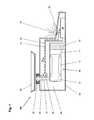
- FIG. 1shows a schematic representation of a force measuring device 100 and a scale in section.
- a load cell 10has a fixed part 11 and a load receiving part 12, which are interconnected by a central part 13.
- the load cell 10is disposed in the interior 80 of a housing 20 and rigidly connected with its stationary part 11 via the housing-fixed support 21 to the housing 20.
- a load receiver 30 arranged outside the housing 20 in the form of a weighing panis connected via a power transmission linkage 14 to the load receiving part 12 of the load cell 10 arranged in the interior 80.
- the power transmission linkage 14penetrates the housing 20 without contact through a housing passage 22.
- the housing bushing 22is designed such that the penetration of dirt, dust and moisture as possible avoided or at least greatly reduced.
- the interior space 80may also have a higher pressure relative to the surroundings of the force-measuring device 100 for this purpose.
- at least one sensor 50is arranged in the interior, which detects at least one parameter of the indoor climate 90 and determines a corresponding sensor signal S HS .
- this sensor signal S HSis forwarded via an arithmetic unit connection 51 to a computing unit 60 and / or forwarded via an output connection 52 to an output 70.
- the arithmetic unit 60is connected to the output 70 via the arithmetic unit output connection 62 and transmits the output signals S HSX generated by the arithmetic unit 60 to the output 70.
- Thiscan be arranged either directly on the outside of the housing 20, separated from the housing 20 , or also be mounted inside the housing, provided that the formation of the housing 20 (sound-permeable, transparent) allows the perception of the output.
- Specially designed symbols and warnings tailored to the message or alert to be issuedmay increase the transmission to a person.
- the use of well-known pictogramssuch as known from the traffic signal signs or specially created for the corresponding warning symbols, conceivable.
- Each of the connections 51, 52, 62 in the embodiment of FIG. 1may be either a cable connection such as a signal cable, a bus system and the like, or a wireless connection.
- a sensor signal S HS or an output signal S HSXis transmitted to the output 70 and displayed accordingly.
- Thismay be an alarm sound, an optical output such as a flashing light or a warning or information displayed on a display.
- FIG. 2shows a monitored according to the inventive method force measuring device 200 in the form of a tank load weighing module.
- Tank load weigh modulesare used particularly in industrial plants for weighing the contents of basins, tanks, reactor vessels and the like. Usually, several weighing modules are arranged between the feet of the container 230 and the foundation 231 per container to be weighed. As a result, each foot of the container stands on a force measuring device 200. In order to determine the weight of the container and / or its contents, the weighing signals S LC generated by the force measuring devices 200 must be added, since these are the weighing signals S LC of partial masses. Therefore, the weight measuring devices 200 in the form of weigh modules usually have no output.
- the weighing signals S LC of the individual force measuring devices 200 of a containerare transmitted, for example, to a computing unit 206 in the form of a master computer, evaluated there and displayed on the integrated in the host computer output 207, usually as part of a system overview.
- the force measuring device 200has a load cell 210, which is enclosed by a housing 220.
- the housing 220is typically welded to the load cell 210 and sealed against the environment of the force measuring device 200. In the measuring insert both the load cell 210 and the housing 220 is elastically compressed.
- the influence of the housing resistance on the weighing signal S LCis partially compensated and the hysteresis of the weighing module relative to the measuring range is negligible.
- the parameters of the indoor climate 290are detected and / or measured by means of sensors 250, 251. These sensors 250, 251 are connected via connection connections 252 and / or radio links 253, transmitters 202, transmitters 203, a segment coupler 204 and a bus system 205 to a computing unit 206.
- the weighing signal S LC of the load cell 210can be transmitted to the arithmetic unit 206 either via these connections or via its own weighing signal connection 254.
- the force measuring device 200 in the interior of the housing 280has a temperature sensor 251 and a humidity sensor 250.
- the independently operable sensors 250, 251have according to the parameters of Indoor climate 290 measured values transmitted to the arithmetic unit 206.
- the arithmetic unit 206 in FIG. 2is, for example, the master computer of a process control system.
- the sensors 250, 251transmit continuously or periodically and / or randomly or after occurrence of a change corresponding sensor signals S HS , S TS to the arithmetic unit 206.
- the arithmetic unit 206, the sensor signals S HS , S TSalso at the sensors 250, 251 continuously, periodically or randomly retrieve.
- the temperature sensor 251has transmitted a sensor signal S TS , which is compared in the arithmetic unit 206 with the upper limit of use T UOU and the lower limit of use T LOU .
- the analysis of the weighing signal S LChas shown that the load cell 210 has been overstressed in the short term and the force measuring device 200 has to be recalibrated. Since several force measuring devices 200 are used per container, the sensor signals S TS , S HS of the respective other force measuring devices 200 can be used to verify the sensor signals S TS , S HS of a force measuring device 200. However, the values for the verification can also already be stored in the sensor 250, 251 or in the arithmetic unit 206. These come, for example, from published tables whose values come from other devices or from Internet data.
- informationsuch as pressure, temperature and radiation ranges or information on earthquake vibration known and can be used to verify the sensor signals.
- S TS , S HSare stored in the arithmetic unit 206 in the sense of a history, the analysis of this history can serve for further knowledge about the state of both the force measuring cells 210 and the sensors 251, 252.
- the verification values and verification tolerance valuesdepend on the sensor used and are usually supplied by the manufacturer of the sensor.
- a sensor signal S TS , S HS supplied by the sensordue to the Physical conditions can not occur, this is detected by the verification of the sensor signals S TS , S HS in the arithmetic unit 206.
- the verification values and verification tolerance valuescan also be determined and / or adjusted with the aid of preceding sensor signals S TS , S HS or by means of the sensor signals S TS , S HS of further sensors.
- the method according to the inventioncan be carried out by means of centralized and / or decentralized parts of a control device of a system, for example with the arithmetic unit 206 and / or the transducers or transmitters 202, 203, which are provided with the corresponding operating programs 208 for this purpose.
- the state of the sensor 250can be displayed exclusively on the output 207 of the arithmetic unit 206 or on the transducers or transmitters 202, 203.
- a division of tasks between the various levels of process controlis also possible.
- the inventive methodcan thus be implemented on any single or multi-stage systems with little effort.
- Transmitter and transmitter 202, 203can also be installed in a mobile device, with the aid of which the individual values of the sensors 250, 251 are queried via radio links 253.
- the individual sensors 250, 251must have an identification code, as is known and used in the prior art for many applications.
- a maximum value K maxcan also be defined, at which, for example, the load cell 10 and the electronic components are destroyed within a very short time.
- the summed loads INT LTHare compared with the lifetime limit value MAX LTH determined by tests, and the remaining service life R LTH1 , R LTH2 , R LTH3 is calculated therefrom . This is transmitted to the output 70 or stored in the arithmetic unit.
- the maintenance limit value L MHmay be mentioned , above which a warning and / or a maintenance request AM is forwarded to the output 70 (FIG. Figure 3c ). Furthermore, when exceeding the maintenance limit value L MH at the time t 6, for example, the measured value output of the The load cell is blocked, the accuracy class of the balance is downgraded, the measured value printouts are provided with warning notices and / or information is automatically provided via internet connections of the manufacturer. This list should not be understood as exhaustive, since in this context many other actions and manifestations of the output are possible.
- FIG. 4is a formed from the continuously detected sensor signals S TS temperature curve of a arranged in the interior of the housing temperature sensor, as well as the generated by the sensor signals S TS in the arithmetic unit output signals or output messages A C , X OU shown.
- the temperature course in FIG. 4ais partially below a lower usage limit T LOU and partially exceeds an upper usage limit T UOU .
- a violation of the limits T LOU, T UOUdoes not lead to the destruction of the load cell. The verification of a limit violation takes place either in the arithmetic unit or in the sensor itself.
- a corresponding signal S TSX OU is transmitted to the output, as shown in FIG. 4b is shown.
- this signalcan bring about an activation of the measuring process, so that weighing by means of the load cell is possible.
- a calibration A Ccan be triggered automatically or requested by the user.
- FIG. 5is the curve formed by the continuously detected weighing signals S LC of the mechanical loads of the load cell and the generated by the weighing signals S LC output signals or output messages A C, A M , A D shown.
- the weighing signal curveexceeds a threshold value F H several times. This represents the limit above which the mechanical load is so great that due to plastic deformation of parts of the load cell 10, the weighing signal S LC influenced, and the load cell 10 is gradually destroyed.
- the magnitude of the threshold value F Hdepends on the materials used in the load cell 10 and must be determined by the manufacturer on a case-by-case basis.
- the transgressions of the threshold value F H and the maximum value F maxare as in FIG. 5b shown as loads INT LTF registered and summed up.
- the summed loads INT LTFare compared with the lifetime limit value MAX LTF determined by tests and from this the remaining service life R LTF1 , R LTF2 , R LTF3 is calculated. This is transmitted to the output 70 or stored in the arithmetic unit.
- the maintenance limit value L MFmay be mentioned , above which a warning and / or a maintenance request AM is forwarded to the output 70 ( FIG. 5c ). Furthermore, when exceeding the maintenance limit L MF as in FIG. 3b For example, the measurement value output of the load cell is blocked, the accuracy class of the balance is downgraded, measured value printouts are provided with warning notices and / or automatically informed via Internet connections of the manufacturer.
- the present inventionhas further advantages, which only indirectly affect the condition detection and lifetime calculation.
- hermetically sealed force measuring devicescan be determined, for example, by comparing the sensor signals of an installed humidity sensor at the delivery and after installation at the customer, whether the force measuring device has been opened during transport or not. This aspect is of great importance especially for calibratable force measuring devices and represents an additional security to the seal.
- suitable, generated by the at least one sensor sensor signalscan also be used to correct the measurement result, to avoid the arrangement of additional sensors, as used for example in the prior art to compensate for hysteresis and / or Drifterscheinmaschine.
Landscapes
- Physics & Mathematics (AREA)
- General Physics & Mathematics (AREA)
- Engineering & Computer Science (AREA)
- Computer Networks & Wireless Communication (AREA)
- Arrangements For Transmission Of Measured Signals (AREA)
- Force Measurement Appropriate To Specific Purposes (AREA)
- Measurement Of Force In General (AREA)
- Excavating Of Shafts Or Tunnels (AREA)
Abstract
Description
Translated fromGermanDie vorliegende Erfindung betrifft ein Verfahren zur Überwachung und/oder zur Bestimmung des Zustandes einer Kraftmessvorrichtung mit mindestens einem, einen Innenraum aufweisenden Gehäuse und mit mindestens einer, im Innenraum des mindestens einen Gehäuses eingebauten Kraftmesszelle, sowie eine zur Ausführung des Verfahrens geeignete Kraftmessvorrichtung.The present invention relates to a method for monitoring and / or determining the state of a force measuring device having at least one housing having an interior space and at least one force measuring cell installed in the interior of the at least one housing and a force measuring device suitable for carrying out the method.
Viele Kraftmessvorrichtungen, insbesondere gravimetrische Messgeräte wie beispielsweise Waagen, Thermogravimetriegeräte, Messgeräte zur gravimetrischen Feuchtigkeitsbestimmung, Wägemodule für Tankanlagen und Reaktorbehälter, Wägemodule und Mehrfachwägevorrichtungen in Abfüll- und Verpackungsanlagen, aber auch Drehmoment- und Beschleunigungsmessvorrichtungen werden hinsichtlich ihrer teilweise sehr aggressiven Einsatzumgebung mit wirkungsvollen Massnahmen vor Zerstörung geschützt. Diese Schutzmassnahmen sind auf die Einsatzumgebung angepasste Gehäuse, welche entsprechende Vorschriften im Bezug auf das Eindringen von Staub, Feuchtigkeit und dergleichen erfüllen müssen, wie diese beispielsweise in den Ingress Protection Ratings nach EN60529 klassifiziert sind.Many force measuring devices, in particular gravimetric measuring devices such as scales, thermo gravimetric devices, gravimetric moisture measuring devices, weighing modules for tank installations and reactor vessels, weighing modules and multiple weighing devices in filling and packaging systems, but also torque and acceleration measuring devices with respect to their sometimes very aggressive environment with effective measures from destruction protected. These protective measures are casings adapted to the environment of use, which must comply with corresponding regulations regarding the penetration of dust, moisture and the like, as are classified, for example, in the Ingress Protection Ratings according to EN60529.
Hochlast- Kraftmesszellen für Wägemodule, so genannte Tank- oder Reaktorbehälter-Wägemodule sind beispielsweise in gasdicht verschweissten, rostfreien Stahlgehäusen eingebaut. Die in solchen Gehäusen untergebrachten Kraftmesszellen arbeiten problemlos, solange das Gehäuse die das Wägesignal beeinträchtigenden Umwelteinflüsse von der Kraftmesszelle fernhält. Meistens werden die Kraftmesszellen bei undichten Gehäusen auch nicht schlagartig zerstört, es findet vielmehr eine schleichende Zerstörung statt, welche häufig erst spät festgestellt wird. Sofern die Messeinrichtung in Industrieanlagen mit hohem Automatisierungsgrad eingebaut ist, kann ein Defekt der Messeinrichtung zu langer Ausfallzeit der Anlage oder zu fehlerhaften Produkten führen.High-load load cells for weighing modules, so-called tank or reactor vessel weighing modules, for example, are installed in gastight welded, stainless steel housings. The load cells housed in such housings work without problems as long as the housing keeps the environmental influences affecting the weighing signal away from the load cell. In most cases, the load cells in leaky cases are not destroyed suddenly, but rather a creeping destruction takes place, which is often detected late. If the measuring device is installed in industrial plants with a high degree of automation, a defect in the measuring device can lead to long downtime of the system or to faulty products.
Je nach Umgebungsbedingungen müssen die Kraftmessvorrichtungen nicht zwingend hermetisch gekapselt sein. Einfachere und kostengünstigere Gehäuse mit berührungsfreien Durchführungen wie sie beispielsweise in der
Oftmals werden Kraftmessvorrichtungen bis zu ihrer Inbetriebnahme über weite Strecken transportiert und zwischengelagert. Dabei kann sich in ungeeigneter Transport- oder Lagerumgebung im Gehäuseinnern ein Kondensat bilden, das die Messperformance empfindlich beeinträchtigen kann.Force measuring devices are often transported and stored over long distances until they are put into operation. In the case of unsuitable transport or storage environment inside the housing a condensate can form, which can affect the measuring performance.
Die Inspektion der Kraftmesszelle ist je nach umgebendem Gehäuse mit sehr hohem Aufwand verbunden oder gar unmöglich. Eine periodische Überprüfung der in Anlagen eingesetzten Kraftmessvorrichtungen ist aufwändig und teuer.Depending on the surrounding housing, the inspection of the load cell is very expensive or even impossible. A periodic review of the force measuring devices used in plants is complex and expensive.
In der
Die
Der vorliegenden Erfindung liegt daher die Aufgabe zugrunde, ein Verfahren zur Überwachung und/oder zur Bestimmung des Zustandes einer, in einem Gehäuse angeordnete Kraftmesszelle anzugeben, ohne dass dieses Gehäuse zwecks Zustandsbestimmung der Kraftmesszelle geöffnet werden muss.The present invention is therefore based on the object of specifying a method for monitoring and / or determining the state of a force measuring cell arranged in a housing, without this housing having to be opened in order to determine the state of the load cell.
Diese Aufgabe wird mit einem Verfahren und einer Kraftmessvorrichtung gelöst, welche die im Anspruch 1 bzw. 10 angegebenen Merkmale aufweisen.This object is achieved by a method and a force measuring device which have the features specified in
In einem Verfahren zur Überwachung und/oder zur Bestimmung des Zustandes einer Kraftmessvorrichtung mit mindestens einem, einen Innenraum aufweisenden Gehäuse und mit mindestens einer, im Innenraum des mindestens einen Gehäuses eingebauten Kraftmesszelle wird durch mindestens einen im Innenraum des Gehäuses oder mindestens einen, am Gehäuse angeordneter Sensor mindestens ein die Lebensdauer der Kraftmesszelle beeinflussender Parameter des Innenraumklimas gemessen und ein, dem gemessenen Parameter des Innenraumklimas entsprechendes Sensorsignal an eine Recheneinheit und/oder an eine Ausgabe übermittelt.In a method for monitoring and / or determining the state of a force measuring device having at least one housing having an interior and at least one built in the interior of the at least one load cell is by at least one in the interior of the housing or at least one, arranged on the housing Sensor measured at least one of the life of the load cell influencing parameters of the indoor climate and a, the measured parameters of the indoor climate corresponding sensor signal transmitted to a computing unit and / or to an output.
Sofern der Parameter des Innenraumklimas auch das Wägesignal der Kraftmessvorrichtung beeinflusst, kann durch den mindestens einen Sensor oder durch einen zusätzlichen Sensor ein dem gemessenen Parameter des Innenraumklimas entsprechendes Sensorsignal der Recheneinheit zugeführt und in der Recheneinheit mit einem oberen Benutzungsgrenzwert und/oder einem unteren Benutzungsgrenzwert verglichen werden. Bei Verletzung eines dieser Benutzungsgrenzwerte wird das Sensorsignal oder ein Ausgabesignal der Recheneinheit an eine Ausgabe übermittelt.If the parameter of the indoor climate also influences the weighing signal of the force measuring device, a sensor signal corresponding to the measured parameter of the indoor climate can be supplied by the at least one sensor or by an additional sensor to the arithmetic unit and compared in the arithmetic unit to an upper limit of use and / or a lower limit of use , If one of these usage limits is violated, the sensor signal or an output signal of the arithmetic unit is transmitted to an output.
Selbstverständlich kann durch den mindestens einen Sensor auch kontinuierlich oder periodisch und/oder zufällig ein Sensorsignal mindestens eines, die Lebensdauer der Kraftmesszelle und/oder das Wägesignal beeinflussenden Parameters des Innenraumklimas ermittelt werden.Of course, by the at least one sensor also continuously or periodically and / or randomly a sensor signal of at least one, the life of the load cell and / or the weighing signal influencing parameters of the indoor climate can be determined.
Eine kontinuierliche Erfassung der Sensorsignale hat den Vorteil, dass der ganze Signalverlauf des Sensors vorhanden ist, welcher über die Belastungshöhe und Belastungsdauer des entsprechenden Parameters des Innenraumklimas auf die Kraftmesszelle Auskunft gibt und dadurch zur Berechnung der Restlebensdauer herangezogen werden kann.A continuous detection of the sensor signals has the advantage that the entire signal waveform of the sensor is present, which gives information about the load level and load duration of the corresponding parameter of the indoor climate to the load cell and thus can be used to calculate the remaining service life.
Zufällig bedeutet in diesem Zusammenhang, dass eine Signalerfassung oder Signalgenerierung nicht nach einem fixen Zeitablauf ausgelöst wird sondern beispielsweise durch einen Zufallsgenerator oder durch den Benutzer initialisiert wird. Diese Initialisierung kann die Erfassung eines einzelnen Signals verursachen, jedoch aber auch über eine vorbestimmte Zeit eine periodische Signalerfassung auslösen.Random in this context means that a signal acquisition or signal generation is not triggered after a fixed time but is initialized for example by a random number generator or by the user. This initialization can cause the detection of a single signal, but also trigger periodic signal acquisition over a predetermined time.
Vorzugsweise wird durch den mindestens einen Sensor die Veränderung mindestens eines, die Lebensdauer der. Kraftmesszelle und/oder das Wägesignal beeinflussenden Parameters des Innenraumklimas detektiert, und ein dieser Veränderung entsprechendes Sensorsignal ermittelt. Dieses Sensorsignal kann automatisch an die Ausgabe oder Recheneinheit weitergeleitet werden.Preferably, by the at least one sensor, the change of at least one, the life of the. Force measuring cell and / or the weighing signal influencing parameters of the indoor climate detected, and a change of this sensor signal corresponding determined. This sensor signal can be automatically forwarded to the output or arithmetic unit.
Unter dem Begriff Recheneinheit werden alle signalverarbeitenden Elemente wie analoge Schaltkreise, digitale Schaltkreise, integrierte Schaltkreise, Prozessoren, Computer und dergleichen verstanden, die die durch den Sensor generierten Sensorsignale mit bereits in der Recheneinheit gespeicherten oder eingestellten Werten vergleichen. Diese Werte, insbesondere Maximalwerte, Schwellwerte und Benutzungsgrenzwerte können aus Regelwerken wie nationalen oder internationalen Normen stammen, aus Vergleichsmessungen ermittelt oder vom Hersteller der Kraftmessvorrichtung festgelegt worden sein.The term computing unit is understood to mean all signal-processing elements such as analog circuits, digital circuits, integrated circuits, processors, computers and the like which compare the sensor signals generated by the sensor with values already stored or set in the arithmetic unit. These values, in particular maximum values, threshold values and limits of use, may originate from regulations such as national or international standards, have been determined from comparative measurements or have been determined by the manufacturer of the force-measuring device.
Maximalwerte und Schwellwerte sind meist abhängig von der Auslegung der Kraftmessvorrichtung und werden in der Regel durch den Hersteller, eventuell aber auch durch den Benutzer festgelegt. Schwellwerte definieren Zustandsgrenzwerte, bei deren Überschreitung ein bleibender Schaden an der Wägezelle verursacht wird, dieser bleibende Schaden aber die Kraftmessvorrichtung nicht prinzipiell unbrauchbar macht. Durch erneute Kalibrierung der Kraftmessvorrichtung nach dem Überschreiten des Schwellwertes kann die Veränderung kompensiert werden. Eine mehrfache Überschreitung des Schwellwerts kann eine schrittweise Zerstörung der Kraftmessvorrichtung bedeuten, bis hin zu einem Zustand, der nicht mehr mittels einer Kalibrierung kompensiert werden kann. Dieser Zustand wird im Maximalwert ausgedrückt und abgebildet. Selbstverständlich kann ein Maximalwert auch durch ein einmaliges Ereignis erreicht werden, sofern sich die im Gehäuse herrschenden Innenraumklima-Werte sehr stark verändern oder weitere Einwirkungen wie beispielsweise Schläge auf die Kraftmessvorrichtung zur Zerstörung derselben führen.Maximum values and threshold values usually depend on the design of the force measuring device and are usually determined by the manufacturer, but possibly also by the user. Thresholds define state limits that, if exceeded, cause permanent damage to the load cell, but this permanent damage does not render the force measuring device unusable in principle. By re-calibrating the force measuring device after exceeding the threshold value, the change can be compensated. A multiple exceeding of the threshold value may mean a gradual destruction of the force measuring device, up to a state that can no longer be compensated by means of a calibration. This condition is expressed in the maximum value and mapped. Of course, a maximum value can also be achieved by a single event, provided that the prevailing in the housing interior climate values change very strong or other effects such as blows on the force measuring device to destroy the same lead.
Diese Werte können in geeigneter Form in der Recheneinheit gespeichert sein. Dabei kann die Kraftmessvorrichtung bei Bedarf auch mehrere Recheneinheiten aufweisen, beispielsweise kann für jeden eingebauten Sensor eine eigene Recheneinheit vorhanden sein. Als Benutzungsgrenzwerte sind beispielsweise festgelegt:
- Luftdruckgrenzen nach OIML R60: +95kPa bis +105kPa
- Temperaturgrenzen nach OIML R60: Klasse II, +10°C bis +30°C Klasse III, -10°C bis +40°C
- Air pressure limits according to OIML R60: + 95kPa to + 105kPa
- Temperature limits according to OIML R60: Class II, + 10 ° C to + 30 ° C Class III, -10 ° C to + 40 ° C
Die Benutzungsgrenzwerte definieren den Innenraumklima-Wertebereich, in welchem die Kraftmesszelle betrieben werden darf ohne die zulässigen Messergebnistoleranzen der Kraftmessvorrichtung zu verletzen.The usage limits define the interior climate value range in which the load cell may be operated without violating the allowable measurement tolerance tolerances of the force measuring device.
Der Begriff Ausgabe steht für alle analog beziehungsweise digital arbeitenden Übermittlungs-, Melde- und Warnsysteme die geeignet sind, die durch den Sensor erzeugten Sensorsignale eines Innenraumklima- Parameters oder ein Ausgangssignal der Recheneinheit durch geeignete Mittel wie Ton, Licht, Vibrationen, elektrische Signale, elektromagnetische Impulse, numerische Ausgaben und dergleichen mehr darzustellen oder an weitere Geräte, beispielsweise weitere Ausgaben, Leitsysteme, Terminals und dergleichen zu übermitteln. Die Ausgabe kann deshalb auch ein Transponder oder Transmitter sein, welcher die Sensorsignale und/oder Ausgangssignale beispielsweise an ein portables Gerät sendet. Mittels der Ausgabe kann eine Warnung an den Benutzer ausgegeben, das Ereignis an eine Speichereinheit weitergesendet oder sogar der Hersteller oder dessen Servicestelle beispielsweise über Internetverbindungen direkt alarmiert werden.The term output stands for all analogue or digitally operating transmission, reporting and warning systems which are suitable, the sensor signals of an indoor climate parameter generated by the sensor or an output signal of the arithmetic unit by suitable means such as sound, light, vibrations, electrical signals, electromagnetic Impulses, numerical outputs and the like to represent or transmit to other devices, such as other expenses, control systems, terminals and the like. The output can therefore also be a transponder or transmitter, which transmits the sensor signals and / or output signals, for example, to a portable device. By means of the output, a warning can be issued to the user, the event can be forwarded to a storage unit or even the manufacturer or his service point can be directly alerted via Internet connections, for example.
Alle Sensoren können aktive Systeme sein, die eine Veränderung selbständig detektieren und ein Sensorsignal an die Recheneinheit und/oder an die Ausgabe weiterleiten. Aber auch passive Sensoren sind verwendbar, wobei die Sensorsignale durch die Recheneinheit periodisch abgefragt werden. Die so erfassten Daten erlauben bereits eine grobe Berechnung der Restlebensdauer, indem bei jeder Verletzung eines Schwellwertes oder Maximalwertes ein vordefinierter Betrag von der vordefinierten Lebensdauer subtrahiert wird. Eine kontinuierliche Erfassung der Sensorsignale analog einem Signalverlauf erlaubt aufgrund der miterfassten Zeitabschnitte eine sehr genaue Berechnung der Restlebensdauer.All sensors can be active systems that independently detect a change and forward a sensor signal to the arithmetic unit and / or to the output. But also passive sensors can be used, wherein the sensor signals are polled periodically by the arithmetic unit. The data thus acquired already allow a rough calculation of the remaining service life by subtracting a predefined amount from the predefined service life for each violation of a threshold or maximum value. A continuous detection of the sensor signals analogous to a signal curve allows a very accurate calculation of the remaining service life due to the time periods included.
Die erfindungsgemässe Anordnung mindestens eines Sensors innerhalb des Wägezellengehäuses erlaubt somit den aktuellen Zustand der Wägezelle zu ermitteln und im Falle mehrerer auftretender Schwellwertverletzungen gegebenenfalls auch die Restlebensdauer zu berechnen. Dabei wird das von einem Sensor ermittelte Sensorsignal in der Recheneinheit mit wenigstens einem Schwellwert verglichen und nach Überschreiten dieses Schwellwerts
- a) eine entsprechende Belastung registriert;
- b) eine entsprechende Belastung registriert und die Summe aller Belastungen berechnet oder
- c) eine entsprechende Belastung registriert und die Summe aller Belastungen berechnet und durch Vergleich mit einem Maximalwert der zulässigen Belastungen eine zulässige Restbelastung oder Restlebensdauer berechnet.
- a) registers a corresponding charge;
- b) registers a corresponding charge and calculates the sum of all charges or
- c) registers a corresponding load and calculates the sum of all loads and calculates a permissible residual load or residual service life by comparison with a maximum value of the permissible loads.
Die Summe der Belastungen beziehungsweise die Restlebensdauer, kann entweder über die Ausgabe von der Recheneinheit abgefragt werden oder die Recheneinheit übermittelt automatisch bei jeder Registrierung einer entsprechenden Belastung, diese Angaben in Form von Ausgangssignalen an die Ausgabe. Dieses Ausgangssignal kann verschiedene Aktionen wie eine Alarmierung oder eine Kalibrierung auslösen, beziehungsweise den Messvorgang der Kraftmessvorrichtung unterbrechen.The sum of the loads or the remaining service life, can either be queried via the output of the arithmetic unit or the arithmetic unit automatically transmits each time a corresponding load, these data in the form of output signals to the output. This output signal can trigger various actions such as an alarm or a calibration, or interrupt the measuring process of the force measuring device.
Grundsätzlich ist es unerheblich, wo der Sensor innerhalb des Gehäuses installiert ist. Er kann an der Innenseite des Wägezellengehäuses oder an der Wägezelle selbst angebracht sein oder auch beispielsweise in der Platine der Signalverarbeitung integriert sein. Sogar an der Aussenseite des Wägezellengehäuses ist eine Anordnung des Sensors vorstellbar, sofern eine geeignete Verbindung zwischen dem Innenraum und dem Sensor besteht, um einen entsprechenden Parameter des Innenraumklimas genügend genau zu erfassen. Zum Beispiel kann ein Temperatursensoren auf der Gehäuse- Aussenseite angebracht sein, wenn die Sensor- Kontaktfläche des Gehäuses einen ausreichende Wärmekonvektion vom Innenraum zum Sensor gewährleistet. Auch Drucksensoren können an der Aussenseite des Gehäuses angebracht sein, sofern eine entsprechende Verbindung zum Innenraum hergestellt ist oder das Gehäuse zumindest eine membranförmig ausgebildete Stelle aufweist, vermittels deren Dehnung der Parameter Druck des Innenraumklimas erfasst werden kann.Basically, it does not matter where the sensor is installed inside the case. It may be attached to the inside of the load cell housing or to the load cell itself or may also be integrated, for example, in the signal processing board. Even on the outside of the load cell housing, an arrangement of the sensor is conceivable, provided that there is a suitable connection between the interior and the sensor in order to detect a corresponding parameter of the indoor climate sufficiently accurately. For example, a temperature sensors may be mounted on the outside of the housing if the sensor contact surface of the housing ensures sufficient heat convection from the interior to the sensor. Also, pressure sensors may be mounted on the outside of the housing, provided that a corresponding connection to the interior is made or the housing has at least one membrane-shaped point, by means of which the expansion pressure of the indoor climate can be detected.
In einer besonders bevorzugten Ausgestaltung wird die Summe aller Belastungen die auf die Kraftmesszelle einwirken, durch Integration
- a) des gesamten Verlaufs der Sensorsignale des mindestens einen Sensors oder
- b) des Verlaufs der Sensorsignale des mindestens einen Sensors nach Überschreiten eines Schwellwerts oder
- c) der Zeitabschnitte während derer die Sensorsignale des mindestens einen Sensors über dem bzw. den Schwellwerten liegt,
- a) the entire course of the sensor signals of the at least one sensor or
- b) the course of the sensor signals of the at least one sensor after exceeding a threshold value or
- c) the time segments during which the sensor signals of the at least one sensor are above the threshold value (s),
Das der Ausgabe zugeführte Sensorsignal oder das Ausgangssignal der Recheneinheit kann verschiedene Aktionen wie eine Alarmierung, beispielsweise über ein Warnsystem oder ein Meldesystem auslösen und/oder einen Messvorgang der Kraftmessvorrichtung unterbrechen. Auch die Löschung einer Bereitschaftsanzeige, welche anzeigt, dass die Kraftmessvorrichtung betriebsbereit ist, ist denkbar.The sensor signal supplied to the output or the output signal of the arithmetic unit can trigger various actions such as alarming, for example via a warning system or a reporting system, and / or interrupt a measuring process of the force-measuring device. The deletion of a readiness display, which indicates that the force measuring device is ready, is conceivable.
In einer Weiterbildung kann das mindestens eine Sensorsignal oder das Ausgangssignal auch einen automatischen Kalibriervorgang der Kraftmesszelle auslösen oder vom Benutzer/Hersteller eine manuell durchgeführte Kalibrierung verlangen.In a development, the at least one sensor signal or the output signal can also trigger an automatic calibration process of the load cell or require the user / manufacturer to perform a manually performed calibration.
In einer bevorzugten Weiterbildung des Verfahrens werden zur Kontrolle des mindestens einen Sensors dessen an die Recheneinheit übermittelten Sensorsignale zumindest periodisch in der Recheneinheit durch einen Vergleich mit in der Recheneinheit gespeicherten oder durch die Recheneinheit gebildeten Verifizierungswerten und Verifizierungstoleranzwerten überprüft und beim Verletzen der Verifizierungswerte und/oder Verifizierungstoleranzwerte ein Fehler registriert und an die Ausgabe übermittelt. Die Verifizierungswerte sind abhängig vom verwendeten Sensor und werden meistens vom Hersteller des Sensors mitgeliefert. Wird während des Betriebs der Kraftmessvorrichtung beispielsweise ein Sensorsignal vom Sensor geliefert, das aufgrund der physikalischen Gegebenheiten nicht auftreten kann, wird dies durch die Verifizierung der Sensorsignale in der Recheneinheit erkannt. Des Weiteren können die Verifizierungswerte und Verifizierungstoleranzwerte auch mit Hilfe vorangegangener Sensorsignale oder mittels der Sensorsignale weiterer Sensoren festgelegt und/oder angepasst werden.In a preferred refinement of the method, the sensor signals transmitted to the arithmetic unit are checked at least periodically in the arithmetic unit by comparison with verification values and verification tolerance values stored in the arithmetic unit or by the arithmetic unit for checking the at least one sensor and violating the verification values and / or verification tolerance values registered an error and sent it to the output. The verification values depend on the sensor used and are usually supplied by the manufacturer of the sensor. If during the operation of the force measuring device, for example, a sensor signal supplied by the sensor, which can not occur due to the physical conditions, this is detected by the verification of the sensor signals in the arithmetic unit. Furthermore, the verification values and verification tolerance values can also be determined and / or adjusted by means of preceding sensor signals or by means of the sensor signals of further sensors.
In einer besonders bevorzugten Weiterbildung wird mindestens ein Sensorsignal vor der Auslieferung der Kraftmessvorrichtung ermittelt, dieses Sensorsignal in der Recheneinheit ausgewertet und als Referenzwert gespeichert, zumindest nach der Auslieferung der Kraftmesszelle mit dem, dem Referenzwert zugeordneten Sensor mindestens ein Sensorsignal ermittelt, dieses Sensorsignal in einem Sensormesswert ausgedrückt und diesen Sensormesswert mit dem Referenzwert verglichen. Dieses Vorgehen kann der Kontrolle dienen, ob die Kraftmessvorrichtung unerlaubt geöffnet worden ist oder nicht.In a particularly preferred development, at least one sensor signal is determined before the delivery of the force-measuring device, this sensor signal in the Arithmetic unit evaluated and stored as a reference value, at least after delivery of the load cell with the sensor associated with the reference value at least one sensor signal, this sensor signal is expressed in a sensor measured value and compared this sensor measured value with the reference value. This procedure can serve to control whether the force measuring device has been opened without permission or not.
Zur Durchführung der vorangehend beschriebenen Verfahren wird eine Kraftmessvorrichtung mit mindestens einem einen Innenraum aufweisenden Gehäuse, mindestens einer im Innenraum eingebauten Kraftmesszelle und mit mindestens einem im Innenraum des Gehäuses und/oder mindestens einem, am Gehäuse angeordneten Sensor benötigt. Der mindestens eine Sensor weist ein Triggerelement auf, wobei mindestens ein Schwellwert und/oder mindestens ein Benutzungsgrenzwert in Abhängigkeit mindestens eines die Lebensdauer der Kraftmesszelle beeinflussenden Parameters des Innenraumklimas im Triggerelement abgebildet ist. Anstelle des Sensors mit Triggerelement kann die Kraftmessvorrichtung auch mindestens einen Sensor und mindestens eine Recheneinheit und/oder eine, die Ausgabe enthaltende Ausgabeeinheit und/oder einen Messumformer sowie ein die Funktion des Triggerns ausführendes Betriebsprogramm aufweisen, wobei das Betriebsprogramm mindestens einen Wert aufweist, welcher einen Schwellwert und/oder einen Benutzungsgrenzwert in Abhängigkeit mindestens eines die Lebensdauer der Kraftmesszelle beeinflussenden Parameters des Innenraumklimas repräsentiert und/oder im Betriebsprogramm mindestens eine Befehlssequenz zum Abfragen mindestens eines Wert aus einem Speichermodul vorhanden ist, welcher mindestens einen Schwellwert und/oder einen Benutzungsgrenzwert und/oder ein Maximalwert repräsentiert. Die Kombination eines Sensors mit Triggerelement und einer Recheneinheit mit Betriebsprogramm ist seibstverständlich auch möglich.To carry out the method described above, a force measuring device with at least one housing having an interior, at least one built-in interior load cell and at least one in the interior of the housing and / or at least one, arranged on the housing sensor is required. The at least one sensor has a trigger element, wherein at least one threshold value and / or at least one usage limit value is mapped as a function of at least one parameter of the indoor climate influencing the service life of the load cell in the trigger element. Instead of the sensor with trigger element, the force measuring device can also have at least one sensor and at least one arithmetic unit and / or an output unit containing the output and / or a transmitter and an operating program executing the function of triggering, wherein the operating program has at least one value, which At least one command sequence for querying at least one value from a memory module, which has at least one threshold value and / or a usage limit value and / or at least one command sequence for querying at least one value from a memory module is present in the operating program and / or a user limit value depending on at least one influencing the life of the load cell parameter of the indoor climate represents a maximum value. The combination of a sensor with trigger element and a computing unit with operating program is of course also possible.
Vorzugsweise wird ein durch das Triggerelement getriggertes Sensorsignal an eine Recheneinheit und/oder an eine Ausgabe übermittelt. Das Triggerelement selbst kann unterschiedlich aufgebaut sein. Beispielsweise ist die Verwendung eines in der
Ein durch das Betriebsprogramm getriggertes Ausgangssignal der Recheneinheit kann auch an eine Ausgabe und/oder an eine weitere Recheneinheit übermittelbar sein. Sofern die Recheneinheit der Kraftmessvorrichtung und/oder eine die Ausgabe enthaltende Ausgabeeinheit und/oder ein mit dem Sensor in Verbindung stehender Messumformer über einen Mikroprozessor verfügt, können einzelne, mehrere oder alle Verfahrensschritte des Verfahrens in einem Betriebsprogramm abgebildet werden, wobei dieses Betriebsprogramm in mindestens einer Speichereinheit, welche mit der Kraftmessvorrichtung zumindest zeitweise in Verbindung steht, abgespeichert ist.An output signal of the arithmetic unit triggered by the operating program can also be transmitted to an output and / or to a further arithmetic unit. If the arithmetic unit of the force-measuring device and / or an output unit containing the output and / or a transmitter connected to the sensor has a microprocessor, individual, several or all method steps of the method can be mapped in an operating program, this operating program in at least one Storage unit, which is at least temporarily in communication with the force measuring device, is stored.
In einer Ausführung muss das vorangehend beschriebene Betriebsprogramm nicht zwingend im Prozessor eingespeichert sein, sondern kann bei Bedarf aus einer Speichereinheit ausserhalb der Kraftmessvorrichtung abgerufen und auf den entsprechenden Prozessor aufgeladen werden.In one embodiment, the above-described operating program does not necessarily have to be stored in the processor, but can, if required, be retrieved from a storage unit outside the force measuring device and charged to the corresponding processor.
In einer Ausgestaltung der Erfindung ist die Recheneinheit und/oder eine, die Ausgabe enthaltende Ausgabeeinheit drahtlos oder drahtgebunden mit dem mindestens einen Sensor verbunden.In one embodiment of the invention, the arithmetic unit and / or an output unit containing the output is connected wirelessly or by wire to the at least one sensor.
In einer vorteilhaften Ausgestaltung der Erfindung ist als mindestens ein Sensor ein Sensor vorgesehen, in den ein Speichermodul und/oder ein Messumformer integriert ist.In an advantageous embodiment of the invention, a sensor is provided as at least one sensor, in which a memory module and / or a transmitter is integrated.
Als Sensor kann beispielsweise ein Feuchtesensor verwendet werden, welcher die Veränderung des Parameters Feuchtigkeit im Innenraum infolge eines Gehäuselecks detektiert und/oder vermittels dieses Sensors ein dem Parameter Feuchtigkeit entsprechendes Sensorsignal periodisch und/oder zufällig oder kontinuierlich ermittelt wird.As a sensor, for example, a humidity sensor can be used, which detects the change in the parameter humidity in the interior due to a housing leakage and / or by means of this sensor, a moisture parameter corresponding sensor signal is determined periodically and / or randomly or continuously.
Ebenso ist als Sensor ein Temperatursensor verwendbar, welcher die Veränderung des Parameters Temperatur im Innenraum infolge einer auf das Gehäuse einwirkenden Strahlung und/oder einer gehäuseintern verursachten Erwärmung detektiert und/oder ein dem Parameter Temperatur entsprechendes Sensorsignal periodisch und/ oder zufällig oder kontinuierlich ermittelt wird.Similarly, as a sensor, a temperature sensor can be used, which is the change in the temperature parameter in the interior as a result of a radiation acting on the housing and / or a housing-internally caused heating detected and / or a parameter corresponding to the temperature sensor signal is determined periodically and / or randomly or continuously.
Eine weitere Möglichkeit stellt die Verwendung eines Drucksensors dar, welcher die Veränderung des Parameters Druck im Innenraum infolge eines Gehäuselecks, einer Gehäusedeformation und/oder einer Erwärmung des Innenraums detektiert und/oder vermittels diesem Sensor ein dem Parameter Druck entsprechendes Sensorsignal periodisch und/oder zufällig oder kontinuierlich ermittelt wird.Another possibility is the use of a pressure sensor, which detects the change in the pressure in the interior due to a housing leakage, housing deformation and / or heating of the interior and / or by means of this sensor, a parameter pressure corresponding sensor signal periodically and / or randomly or is determined continuously.
Die Kraftmessvorrichtung kann zusätzlich zum mindestens einen Sensor einen weiteren Sensor im Innenraum des Gehäuses oder am Gehäuse zur Detektierung von Netzspannungsspitzen in einer die Kraftmesszelle speisenden Stromversorgung aufweisen.The force measuring device may have, in addition to the at least one sensor, a further sensor in the interior of the housing or on the housing for detecting mains voltage peaks in a power supply cell feeding the power supply.
Des Weiteren kann zusätzlich zum mindestens einen Sensor mindestens ein weiterer Sensor im Innenraum des Gehäuses oder am Gehäuse zur Detektierung von radioaktiver Bestrahlung und/oder von Schallwellen und/oder von Schlägen angeordnet sein.Furthermore, in addition to the at least one sensor, at least one further sensor may be arranged in the interior of the housing or on the housing for detecting radioactive radiation and / or sound waves and / or beats.
Ferner kann die Kraftmessvorrichtung im Innenraum des Gehäuses oder am Gehäuse zusätzlich zum mindestens einen Sensor einen weiteren Sensor zur Ermittlung eines Sensorsignals in Abhängigkeit der Belastungszyklen der Kraftmesszelle aufweisen.Furthermore, the force measuring device in the interior of the housing or on the housing in addition to at least one sensor, a further sensor for detecting a sensor signal in dependence on the load cycles of the load cell.
Anstelle eines zusätzlichen Sensors können die mechanischen Belastungen aber auch direkt in der Recheneinheit aus dem Wägesignal der Kraftmesszelle ermittelt werden.Instead of an additional sensor, the mechanical loads can also be determined directly in the arithmetic unit from the weighing signal of the load cell.
Die Sensoren der Kraftmessvorrichtung können so ausgebildet sein, dass in jedem Sensor ein Speichermodul und/oder ein Messumformer und/oder ein Transmitter integriert ist.The sensors of the force measuring device can be designed so that in each sensor, a memory module and / or a transmitter and / or a transmitter is integrated.
Einzelheiten des erfindungsgemässen Verfahrens und der erfindungsgemässen Kraftmessvorrichtung ergeben sich anhand der Beschreibung der in den Zeichnungen dargestellten Ausführungsbeispiele. Es zeigen:
Figur 1 in schematischer Darstellung eine Kraftmessvorrichtung in Gestalt einer Waage im Schnitt, mit einem einen Innenraum aufweisenden Gehäuse und einer im Gehäuse angeordneten Kraftmesszelle, wobei der Innenraum zur Durchführung des erfindungsgemässen Verfahrens mindestens einen Sensor aufweist;Figur 2 in schematischer Darstellung eine Kraftmessvorrichtung in Gestalt eines Tanklast- Wägemoduls im Schnitt mit einem einen Innenraum aufweisenden Gehäuse und einer im Gehäuse angeordneten Kraftmesszelle, wobei der Innenraum zur Durchführung des erfindungsgemässen Verfahrens zwei Sensoren aufweist welche über Verbindungseinrichtungen mit einer, ausserhalb des Gehäuse angeordneten Ausgabeeinheit verbunden sind;Figur 3 den Signalverlauf eines im Innenraum des Gehäuses angeordneten Feuchtesensors, wobei in 3a der Signalverlauf, in 3b die aufsummierten Belastungen und in 3c die durch den Signalverlauf generierten Ausgabesignale beziehungsweise Ausgabemeldungen dargestellt sind,Figur 4 den Signalverlauf eines im Innenraum des Gehäuses angeordneten Temperatursensors, wobei in 4a der Signalverlauf und in 4 b die durch den Signalverlauf generierten Ausgabesignale beziehungsweise Ausgabemeldungen dargestellt sind,Figur 5 den Signalverlauf des Wägesignals der Kraftmesszelle, wobei in 5a der Signalverlauf, in 5b die aufsummierten Belastungen und in 5c die durch den Signalverlauf generierten Ausgabesignale beziehungsweise Ausgabemeldungen dargestellt sind.
FIG. 1 a schematic representation of a force measuring device in the form of a scale in section, with a housing having an interior and a in Housing arranged load cell, wherein the interior for performing the inventive method has at least one sensor;FIG. 2 in a schematic representation of a force measuring device in the form of a tank load weighing module in section with an interior housing and a housing arranged in the load cell, wherein the interior for performing the inventive method comprises two sensors which are connected via connecting means with a, outside the housing arranged output unit ;FIG. 3 FIG. 3 a shows the signal course, in FIG. 3 b the accumulated loads and in FIG. 3 c the output signals or output messages generated by the signal progression, FIG. 3 c shows the signal course of a humidity sensor arranged in the interior of the housing,FIG. 4 FIG. 4 a shows the signal course and in FIG. 4 b the output signals or output messages generated by the signal curve, FIG. 4 a shows the signal course of a temperature sensor arranged in the interior of the housing;FIG. 5 FIG. 5 a shows the signal course, in FIG. 5 b the accumulated loads and in FIG. 5 c the output signals or output messages generated by the signal progression.
Die
Die Gehäusedurchführung 22 ist derart ausgebildet, dass ein Eindringen von Schmutz, Staub und Feuchtigkeit möglichst vermieden oder zumindest stark reduziert wird. Je nach Anwendung kann der Innenraum 80 gegenüber der Umgebung der Kraftmessvorrichtung 100 zu diesem Zweck auch einen höheren Druck aufweisen. Ferner ist im Innenraum mindestens ein Sensor 50 angeordnet, welcher mindestens einen Parameter des Innenraumklimas 90 erfasst und ein dazu korrespondierendes Sensorsignal SHS ermittelt. Dieses Sensorsignal SHS wird zwecks weiterer Verarbeitung über eine Recheneinheit-Verbindung 51 an eine Recheneinheit 60 weitergeleitet und/oder über eine Ausgabe-Verbindung 52 an eine Ausgabe 70 weitergeleitet. Die Recheneinheit 60 ist über die Recheneinheit- Ausgabe- Verbindung 62 mit der Ausgabe 70 verbunden und übermittelt die von der Recheneinheit 60 generierten Ausgangssignale SHSX an die Ausgabe 70. Diese kann entweder direkt an der Aussenseite des Gehäuses 20 angeordnet, vom Gehäuse 20 getrennt angeordnet, oder auch innerhalb des Gehäuses montiert sein, sofern die Ausbildung des Gehäuses 20 (schalldurchlässig, transparent) die Wahrnehmung der Ausgabe ermöglicht. Speziell auf die auszugebende Mitteilung oder Warnung zugeschnittene Symbole und Warnhinweise können die Übermittlung an eine Person verstärken. So ist die Verwendung allgemein bekannter Piktogramme, wie beispielsweise aus dem Strassenverkehr bekannte Signalschilder oder eigens für die entsprechende Warnung kreierte Symbole, denkbar. Mittels der Variierung der Frequenz blinkender visueller Ausgabemittel oder auch der Variierung von Lautstärke und Tonfrequenz phonetischer Ausgabemittel kann der Grad der Wichtigkeit der Warnung oder Meldung variiert werden. Jede der Verbindungen 51, 52, 62 im Ausführungsbeispiel von
Sobald ein Parameter des Innenraumklimas 90, in diesem Ausführungsbeispiel die relative Feuchte, sich verändert oder den vom Hersteller definierten zulässigen Wert übersteigt, wird ein Sensorsignal SHS oder ein Ausgangssignal SHSX an die Ausgabe 70 übermittelt und dort entsprechend angezeigt. Dies kann ein Alarmton, eine optische Ausgabe wie ein Blinklicht oder eine, auf einem Display dargestellte Warnung oder Information sein.As soon as a parameter of the
Die Kraftmessvorrichtung 200 weist eine Kraftmesszelle 210 auf, welche von einem Gehäuse 220 umschlossen ist. Das Gehäuse 220 ist in der Regel mit der Kraftmesszelle 210 verschweisst und gegenüber der Umgebung der Kraftmessvorrichtung 200 dicht verschlossen. Im Messeinsatz wird sowohl die Kraftmesszelle 210 als auch das Gehäuse 220 elastisch gestaucht. Der Einfluss des Gehäusewiderstandes auf das Wägesignal SLC ist teilweise kompensierbar und die Hysterese des Wägemoduls bezogen auf den Messbereich vernachlässigbar. Die Parameter des Innenraumklimas 290 werden mittels Sensoren 250, 251 detektiert und/oder gemessen. Diese Sensoren 250, 251 sind über Anschluss-Verbindungen 252 und/oder Funkverbindungen 253, Transmitter 202, Messumformer 203, einen Segmentkoppler 204 und ein Bussystem 205 mit einer Recheneinheit 206 verbunden. Das Wägesignal SLC der Kraftmesszelle 210 kann entweder über diese Verbindungen oder über eine eigene Wägesignal- Verbindung 254 an die Recheneinheit 206 übertragen werden.The
In
Als Feuchtesensoren, Temperatursensoren, Schocksensoren Stromwandler, Spannungswandler und dergleichen können alle im Stand der Technik bekannten Sensoren eingesetzt werden die in der Lage sind, ein der zu erfassenden Veränderung oder Messgrösse entsprechendes Sensorsignal zu bilden.As humidity sensors, temperature sensors, shock sensors, current transformers, voltage transformers and the like, it is possible to use all sensors known from the prior art which are capable of forming a sensor signal corresponding to the change or measured quantity to be detected.
Das erfindungsgemässe Verfahren kann mittels zentralisierten und/oder dezentralisierten Teilen einer Steuervorrichtung einer Anlage, beispielsweise mit der Recheneinheit 206 und/oder den Messumformern bzw. Transmittern 202, 203 durchgeführt werden, die dazu mit den entsprechenden Betriebsprogrammen 208 versehen sind. Beispielsweise kann der Zustand des Sensors 250 ausschliesslich auf der Ausgabe 207 der Recheneinheit 206 oder auf den Messumformern bzw. Transmittern 202, 203 angezeigt werden. Möglich ist jedoch auch eine Aufgabenteilung zwischen den verschiedenen Ebenen der Prozesssteuerung. Durch geeignete Massnahmen kann das erfindungsgemässe Verfahren somit auf beliebigen ein- oder mehrstufigen Anlagen mit geringem Aufwand implementiert werden. Messumformer und Transmitter 202, 203 können auch in einem mobilen Gerät eingebaut sein, mit dessen Hilfe die einzelnen Werte der Sensoren 250, 251 über Funkverbindungen 253 abgefragt werden. Dazu müssen die einzelnen Sensoren 250, 251 über einen Identifikationscode verfügen, wie dies im Stand der Technik für viele Anwendungen bekannt ist und verwendet wird.The method according to the invention can be carried out by means of centralized and / or decentralized parts of a control device of a system, for example with the
In
- Vibrationsgrenzen: 0.196133m/s2
- Max./Min. Lagertemperaturgrenzen: -20°C bis +70°C
- Netzspannungsspitzen (Störung oder Zerstörung von elektrischen Komponenten)
- Belastungszyklen (Ermüdungsgrenzen)
- Vibration limits: 0.196133m /s2
- Max./Min. Storage temperature limits: -20 ° C to + 70 ° C
- Mains voltage peaks (interference or destruction of electrical components)
- Load cycles (fatigue limits)
Sobald der Schwellwert KH wie in den Zeitpunkten t2, t4, t7 unterschritten wird, wird der Zustand stabilisiert und die Zerstörung im Innenraum 80 der Kraftmessvorrichtung 100 schreitet nicht weiter voran. Wie in
Ferner kann auch ein Maximalwert Kmax definiert werden, bei dessen Überschreitung beispielsweise die Kraftmesszelle 10 und die elektronischen Komponenten innerhalb kürzester Zeit zerstört werden.Furthermore, a maximum value Kmax can also be defined, at which, for example, the
Die Überschreitungen des Schwellwertes KH und des Maximalwertes Kmax in Abhängigkeit der Überschreitungszeit (t2- t1; t4- t3; t7-t5;...) werden wie in
Wie in
Sobald die Belastungen INTLTH den Lebensdauergrenzwert MAXLTH überschreiten, wird wie in
In
In
Wenn das Wägesignal SLC unterhalb des Schwellwerts FH liegt, werden die Materialien im elastischen Bereich beansprucht, was die Kraftmesszelle nicht zerstört. Wie in
Ferner kann auch ein Maximalwert Fmax definiert werden, bei dessen Überschreitung davon ausgegangen werden kann, dass die Kraftmesszelle 10 durch eine entsprechend hohe, mechanische Belastung zerstört worden sind.Furthermore, it is also possible to define a maximum value Fmax which, if exceeded, can be assumed to have been destroyed by a correspondingly high mechanical load.
Die Überschreitungen des Schwellwertes FH und des Maximalwertes Fmax werden wie in
Wie in
Sobald die Belastungen INTLTF den Lebensdauergrenzwert MAXLTF überschreiten, wird wie in
Die vorliegende Erfindung birgt noch weitere Vorteile, welche nur indirekt die Zustandserfassung und Lebensdauerberechnung betreffen. Bei hermetisch gekapselten Kraftmessvorrichtungen kann beispielsweise durch einen Vergleich der Sensorsignale eines installierten Feuchtesensors bei der Auslieferung und nach der Installation beim Kunden sogar festgestellt werden, ob die Kraftmessvorrichtung während des Transports geöffnet worden ist oder nicht. Dieser Aspekt ist insbesondere bei eichfähigen Kraftmessvorrichtungen von grosser Bedeutung und stellt eine zusätzliche Sicherheit zum Siegel dar.The present invention has further advantages, which only indirectly affect the condition detection and lifetime calculation. In hermetically sealed force measuring devices can be determined, for example, by comparing the sensor signals of an installed humidity sensor at the delivery and after installation at the customer, whether the force measuring device has been opened during transport or not. This aspect is of great importance especially for calibratable force measuring devices and represents an additional security to the seal.
Zudem können geeignete, von dem mindestens einen Sensor generierte Sensorsignale auch zur Korrektur des Messergebnisses herangezogen werden, um die Anordnung zusätzlicher Messfühler zu vermeiden, wie sie beispielsweise im Stand der Technik zur Kompensation von Hysterese- und/oder Drifterscheinungen verwendet werden.In addition, suitable, generated by the at least one sensor sensor signals can also be used to correct the measurement result, to avoid the arrangement of additional sensors, as used for example in the prior art to compensate for hysteresis and / or Drifterscheinungen.
Die Ausführungsbeispiele in der Beschreibung sollen nicht dahingehend verstanden werden, dass die vorliegende Erfindung auf die Anordnung von nur einer Zelle in nur einem Gehäuse limitiert ist. Es liegt im Verständnis des Fachmannes, die Erfindung ebenso in Anordnungen anzuwenden, die mindestens zwei Wägezellen in einem Gehäuse beinhalten. Des Weiteren spielt die Koordination von Messungen und Warnungen im Bezug auf den Erfindungsgegenstand keine Rolle. Sowohl Meldungen / Warnungen in "Echtzeit" als auch Meldungen / Warnungen zeitlich zu den Messungen versetzt sind möglich.The exemplary embodiments in the description should not be understood to mean that the present invention is limited to the arrangement of only one cell in only one housing. It will be understood by those skilled in the art to apply the invention to arrangements including at least two load cells in a housing. Furthermore, the coordination of measurements and warnings in relation to the subject invention plays no role. Both messages / warnings in "real time" and messages / warnings offset in time to the measurements are possible.
- 210, 10210, 10
- KraftmesszelleLoad cell
- 1111
- feststehender Teilfixed part
- 1212
- LastaufnahmeteilLoad bearing member
- 1313
- Mittelteilmidsection
- 1414
- KraftübertragungsgestängeTransmission rod
- 220, 20220, 20
- Gehäusecasing
- 2121
- gehäusefester Supportfixed housing support
- 2222
- GehäusedurchführungHousing bushing
- 3030
- Lastaufnehmerload sensor
- 5050
- Sensorsensor
- 5151
- Recheneinheit- VerbindungComputer unit connection
- 5252
- Ausgabe- VerbindungOutput connection
- 6060
- Recheneinheitcomputer unit
- 6262
- Recheneinheit- Ausgabe- VerbindungCompute unit output connection
- 7070
- Ausgabeoutput
- 280, 80280, 80
- Innenrauminner space
- 290, 90290, 90
- Parameter des InnenraumklimasParameters of the indoor climate
- 200, 100200, 100
- KraftmessvorrichtungForce measuring device
- 202202
- Transmittertransmitter
- 203203
- Messumformertransmitters
- 204204
- Segmentkopplersegment
- 205205
- Bussystembus system
- 206206
- Recheneinheit / LeitrechnerArithmetic unit / master computer
- 207207
- Ausgabe / LeitrechnerAusgabeOutput / host output
- 208208
- Betriebsprogrammoperating program
- 230230
- Behälterfusscontainer foot
- 231231
- Fundamentfoundation
- 250250
- Feuchtesensorhumidity sensor
- 251251
- Temperatursensortemperature sensor
- 252252
- Anschluss- VerbindungConnection connection
- 253253
- Funk- VerbindungWireless connection
- 254254
- Wägesignal- VerbindungWeighing signal connection
Claims (19)
- Method of monitoring and/or determining the condition of a force-measuring device (100, 200) with at least one housing (20, 220) comprising an interior space (80, 280) and with at least one force-measuring cell (10, 210) installed in the interior space (80, 280) of the at least one housing (20, 220), wherein at least one parameter (90, 290) of the internal atmosphere affecting the operating life of the force-measuring cell (10, 210) is measured by at least one sensor (50, 250, 251) arranged in the interior space (80, 280) of the housing (20, 220) and/or on the housing (20, 220), and wherein a sensor signal (SHS, STS) representing the measured parameter (90, 290) of the internal atmosphere is transmitted to a computer unit (60, 206) and/or to an output device (70, 207),characterized in that the sensor signal (SHS, STS, SLC) is compared in the computer unit (60, 206) to at least one threshold value (KH, FH) and that after the threshold value (KH, FH) has been exceeded, a corresponding stress load is registered, that the sum of all stress loads (INTLTF, INTLTH) is calculated and compared to a respective maximum permissible value (MAXLTF, MAXLTH) of the stress loads, and that based on this comparison, a permissible remaining operating life (RLTH, RLTF) up to the probably final internal breakdown of the force-measuring device (100, 200) is calculated.
- Method according to claim 1,characterized in that at least one parameter (90, 290) of the internal atmosphere affecting the weighing signal (SLC) of the force-measuring cell (10, 210) is measured by the at least one sensor (50, 250, 251) or by an additional sensor (50, 250, 251), that a sensor signal (STS) representing the measured parameter (90, 290) of the internal atmosphere is compared in the computer unit (60, 206) to an upper operating limit (TUOU) and/or to a lower operating limit (TLOU), and that if one of the operating limits (TUOU, TLOU) has been violated, the sensor signal (STS) or an output signal (SHSX) of the computer unit (60, 206) is transmitted to an output device (70, 207).
- Method according to claim 1 or 2,characterized in that a sensor signal (SHS, STS) representing at least one parameter (90, 290) of the internal atmosphere affecting the operating life of the force-measuring cell (10, 210) and/or the weighing signal (SLC) is determined either continuously or periodically and/or at random intervals by the at least one sensor (50, 250, 251).
- Method according to one of the claims 1 to 3,characterized in that a change of at least one parameter (90, 290) of the internal atmosphere affecting the operating life of the force-measuring cell (10, 210) and/or the weighing signal (SLC) is determined by the at least one sensor (50, 250, 251), and that a sensor signal (SHS, STS) is determined representing said change.
- Method according to claim 1,characterized in that the sum of all stress loads (INTLTF, INTLTH) affecting the force-measuring device (100, 200) is determined by integration ofa) the entire time profile of the sensor signals (SHS, STS, SLC), orb) the time profile of the sensor signals (SHS, STS, SLC) after a threshold value (KH, FH) has been exceeded, orc) the time intervals ((t2-t1), (t4-t3), (t7-t5)) during which the sensor signals (SHS, STS, SLC) are exceeding one or both of the threshold values (KH, FH),and that after the maximum permissible value (MAXLTF, MAXLTH) has been exceeded, the condition of the force-measuring device (100, 200), specifically the fact that the maximum permissible value (MAXLTF, MAXLTH) has been exceeded, is transmitted to the output device.
- Method according to one of the claims 1 to 5,characterized in that the sensor signal (SHS, STS, SLC) transmitted to the output device (70, 207) or the output signal (SHSX) of the computer unit triggers an alarm and/or interrupts a measurement process and/or turns off an operational readiness indicator.
- Method according to one of the claims 5 or 6,characterized in that the at least one sensor signal (SHS, STS, SLC) or the output signal (SHSX) of the computer unit triggers an automatic calibration cycle (AC) of the force-measuring cell (10, 210) or indicates that the user or the manufacturer needs to perform a manual calibration (AC).
- Method according to one of the claims 1 to 7,characterized in that, for the purpose of checking the at least one sensor (50, 250, 251), the sensor signals (SHS, STS, SLC) transmitted from the latter to the computer unit (60, 206) are checked in the computer unit (60, 206) at least periodically by comparing them to verification values and verification tolerance values stored in the computer unit (60, 206) and that, if the comparison indicates a deviation from the verification values or a violation of verification tolerance values, an error is registered and transmitted to the output device (70, 207).
- Method according to one of the claims 1 to 8,characterized in that at least one sensor signal (SHS, STS, SLC) is determined prior to delivery of the force-measuring device (100, 200), that said sensor signal (SHS, STS, SLC) is stored in the computer unit as a reference value and that, at least after the delivery of the force-measuring cell, at least one sensor signal (SHS, STS, SLC) is determined using the sensor (50, 250, 251) associated with the reference value, and that the latter sensor signal (SHS, STS, SLC) is compared to the reference value.
- Force-measuring device (100, 200), operable to carry out the method according to one of the claims 1 to 9, with at least one housing (20, 220) comprising an interior space (80, 280), further with at least one force-measuring cell (10, 210) installed in the interior space (80, 280) of the at least one housing (20, 220), and with at least one sensor (50, 250, 251) arranged in the interior space (80, 280) of the housing (20, 220) and/or on the housing (20, 220),characterized in that a computer unit is provided which is operable to compare the sensor signal (SHS, STS, SLC) to at least one threshold value (KH, FH) and, after the threshold value (KH, FH) has been exceeded, to register a corresponding stress load, to calculate the sum of all stress loads (INTLTF, INTLTH) to compare said sum to a respective maximum permissible value (MAXLTF, MAXLTH) of the stress loads, and to calculate, based on said comparison, a permissible remaining operating life (RLTH, RLTF) up to the probably final internal breakdown of the force-measuring device (100, 200), whereina) the at least one sensor (50, 250, 251) comprises a trigger element, wherein at least one threshold value (KH, FH) and/or at least one operating limit (TUOU, TLOU) of at least one parameter (90, 290) of the internal atmosphere affecting the operating life of the force-measuring cell (10, 210) is reflected in the trigger element, and/orb) at least one output unit comprising the output device (70, 207) and/or a measurement converter (203, 204, 205) and an operating program (208) performing the function of issuing a trigger signal are functionally assigned to the force-measuring device (100, 200),b1) wherein the operating program (208) contains at least one value representing at least one threshold value (KH, FH) and/or at least one operating limit (TUOU, TLOU) of at least one parameter (90, 290) of the internal atmosphere affecting the operating life of the force-measuring cell (10, 210), and/orb2) wherein a sequence of commands serves to acquire from a memory module at least one value representing a threshold value and/or an operating limit and/or a maximum permissible value.
- Force-measuring device (100, 200) according to claim 10,characterized in that a sensor signal (SHS, STS) triggered by the trigger element can be transmitted to a computer unit (60, 206) and/or to an output device (70, 207).
- Force-measuring device (100, 200) according to one of the claims 10 or 11,characterized in that an output signal (SHX) of the computer unit triggered by the operating program (208) can be transmitted to an output device (70, 207) and/or to a further computer unit (60, 206) .
- Force-measuring device (100, 200) according to one of the claims 10 to 12characterized in that the computer unit (60, 206) and/or an output unit comprising the output device (70, 207) are connected to the at least one sensor (50, 250, 251) through a wireless or wire- bound connection.
- Force-measuring device (100, 200) according to one of the claims 10 to 13characterized in that at least one sensor (50, 250, 251) is provided in which a memory module and/or a measurement converter is incorporated.
- Force-measuring device (100, 200) according to one of the claims 10 to 14characterized in that the at least one sensor (50, 250) is a humidity sensor (50, 250), a pressure sensor or a temperature sensor (251).
- Force-measuring device (100, 200) according to one of the claims 10 to 15characterized in that in addition to the at least one sensor (50, 250, 251), there is a further sensor arranged in the interior space (80, 280) of the housing (20, 220) or on the housing (20, 220) for the detection of line power peaks in a power supply feeding the force-measuring cell (10, 210).
- Force-measuring device (100, 200) according to one of the claims 10 to 16,characterized in that in addition to the at least one sensor (50, 250, 251), at least one further sensor is arranged in the interior space (80, 280) of the housing (20, 220) or on the housing for the detection of radioactive radiation and/or sound waves and/or impacts.
- Force-measuring device (100, 200) according to one of the claims 10 to 17,characterized in that in addition to the at least one sensor (50, 250, 251), at least one further sensor is arranged in the interior space (80, 280) of the housing (20, 220) or on the housing to determine a sensor signal (SLC) dependent on the load cycles of the force-measuring cell (10, 210).
- Force-measuring device (100, 200) according to one of the claims 10 to 18,characterized in that a sensor signal (SLC) dependent on the load cycles can be determined directly from the weighing signal of the force-measuring cell (10, 210).
Priority Applications (6)
| Application Number | Priority Date | Filing Date | Title |
|---|---|---|---|
| EP05110766AEP1785703B1 (en) | 2005-11-15 | 2005-11-15 | Method for monitoring and/or determining the condition of a force measuring device and force measuring device |
| AT05110766TATE538366T1 (en) | 2005-11-15 | 2005-11-15 | METHOD FOR MONITORING AND/OR DETERMINING THE STATE OF A FORCE MEASURING DEVICE AND FORCE MEASUREMENT DEVICE |
| PL05110766TPL1785703T3 (en) | 2005-11-15 | 2005-11-15 | Method for monitoring and/or determining the condition of a force measuring device and force measuring device |
| CN200610143937XACN1967175B (en) | 2005-11-15 | 2006-11-07 | Method of monitoring and/or determining the condition of a force-measuring device, and force-measuring device |
| JP2006306159AJP5172136B2 (en) | 2005-11-15 | 2006-11-13 | Method and device for monitoring and / or determining the state of a force measuring device |
| US11/559,526US7497137B2 (en) | 2005-11-15 | 2006-11-14 | Method of monitoring and/or determining the condition of a force-measuring device, and force-measuring device |
Applications Claiming Priority (1)
| Application Number | Priority Date | Filing Date | Title |
|---|---|---|---|
| EP05110766AEP1785703B1 (en) | 2005-11-15 | 2005-11-15 | Method for monitoring and/or determining the condition of a force measuring device and force measuring device |
Publications (2)
| Publication Number | Publication Date |
|---|---|
| EP1785703A1 EP1785703A1 (en) | 2007-05-16 |
| EP1785703B1true EP1785703B1 (en) | 2011-12-21 |
Family
ID=35911293
Family Applications (1)
| Application Number | Title | Priority Date | Filing Date |
|---|---|---|---|
| EP05110766AActiveEP1785703B1 (en) | 2005-11-15 | 2005-11-15 | Method for monitoring and/or determining the condition of a force measuring device and force measuring device |
Country Status (6)
| Country | Link |
|---|---|
| US (1) | US7497137B2 (en) |
| EP (1) | EP1785703B1 (en) |
| JP (1) | JP5172136B2 (en) |
| CN (1) | CN1967175B (en) |
| AT (1) | ATE538366T1 (en) |
| PL (1) | PL1785703T3 (en) |
Families Citing this family (335)
| Publication number | Priority date | Publication date | Assignee | Title |
|---|---|---|---|---|
| US20070084897A1 (en) | 2003-05-20 | 2007-04-19 | Shelton Frederick E Iv | Articulating surgical stapling instrument incorporating a two-piece e-beam firing mechanism |
| US9060770B2 (en) | 2003-05-20 | 2015-06-23 | Ethicon Endo-Surgery, Inc. | Robotically-driven surgical instrument with E-beam driver |
| US9072535B2 (en) | 2011-05-27 | 2015-07-07 | Ethicon Endo-Surgery, Inc. | Surgical stapling instruments with rotatable staple deployment arrangements |
| US8215531B2 (en) | 2004-07-28 | 2012-07-10 | Ethicon Endo-Surgery, Inc. | Surgical stapling instrument having a medical substance dispenser |
| US11998198B2 (en) | 2004-07-28 | 2024-06-04 | Cilag Gmbh International | Surgical stapling instrument incorporating a two-piece E-beam firing mechanism |
| US11890012B2 (en) | 2004-07-28 | 2024-02-06 | Cilag Gmbh International | Staple cartridge comprising cartridge body and attached support |
| US11484312B2 (en) | 2005-08-31 | 2022-11-01 | Cilag Gmbh International | Staple cartridge comprising a staple driver arrangement |
| US7934630B2 (en) | 2005-08-31 | 2011-05-03 | Ethicon Endo-Surgery, Inc. | Staple cartridges for forming staples having differing formed staple heights |
| US10159482B2 (en) | 2005-08-31 | 2018-12-25 | Ethicon Llc | Fastener cartridge assembly comprising a fixed anvil and different staple heights |
| US11246590B2 (en) | 2005-08-31 | 2022-02-15 | Cilag Gmbh International | Staple cartridge including staple drivers having different unfired heights |
| US7669746B2 (en) | 2005-08-31 | 2010-03-02 | Ethicon Endo-Surgery, Inc. | Staple cartridges for forming staples having differing formed staple heights |
| US9237891B2 (en) | 2005-08-31 | 2016-01-19 | Ethicon Endo-Surgery, Inc. | Robotically-controlled surgical stapling devices that produce formed staples having different lengths |
| US20070106317A1 (en) | 2005-11-09 | 2007-05-10 | Shelton Frederick E Iv | Hydraulically and electrically actuated articulation joints for surgical instruments |
| US8708213B2 (en) | 2006-01-31 | 2014-04-29 | Ethicon Endo-Surgery, Inc. | Surgical instrument having a feedback system |
| US7753904B2 (en) | 2006-01-31 | 2010-07-13 | Ethicon Endo-Surgery, Inc. | Endoscopic surgical instrument with a handle that can articulate with respect to the shaft |
| US11793518B2 (en) | 2006-01-31 | 2023-10-24 | Cilag Gmbh International | Powered surgical instruments with firing system lockout arrangements |
| US11278279B2 (en) | 2006-01-31 | 2022-03-22 | Cilag Gmbh International | Surgical instrument assembly |
| US8820603B2 (en) | 2006-01-31 | 2014-09-02 | Ethicon Endo-Surgery, Inc. | Accessing data stored in a memory of a surgical instrument |
| US20110295295A1 (en) | 2006-01-31 | 2011-12-01 | Ethicon Endo-Surgery, Inc. | Robotically-controlled surgical instrument having recording capabilities |
| US20120292367A1 (en) | 2006-01-31 | 2012-11-22 | Ethicon Endo-Surgery, Inc. | Robotically-controlled end effector |
| US8186555B2 (en) | 2006-01-31 | 2012-05-29 | Ethicon Endo-Surgery, Inc. | Motor-driven surgical cutting and fastening instrument with mechanical closure system |
| US11224427B2 (en) | 2006-01-31 | 2022-01-18 | Cilag Gmbh International | Surgical stapling system including a console and retraction assembly |
| US7845537B2 (en) | 2006-01-31 | 2010-12-07 | Ethicon Endo-Surgery, Inc. | Surgical instrument having recording capabilities |
| US8992422B2 (en) | 2006-03-23 | 2015-03-31 | Ethicon Endo-Surgery, Inc. | Robotically-controlled endoscopic accessory channel |
| US8322455B2 (en) | 2006-06-27 | 2012-12-04 | Ethicon Endo-Surgery, Inc. | Manually driven surgical cutting and fastening instrument |
| US10568652B2 (en) | 2006-09-29 | 2020-02-25 | Ethicon Llc | Surgical staples having attached drivers of different heights and stapling instruments for deploying the same |
| US11980366B2 (en) | 2006-10-03 | 2024-05-14 | Cilag Gmbh International | Surgical instrument |
| US11291441B2 (en) | 2007-01-10 | 2022-04-05 | Cilag Gmbh International | Surgical instrument with wireless communication between control unit and remote sensor |
| US8632535B2 (en) | 2007-01-10 | 2014-01-21 | Ethicon Endo-Surgery, Inc. | Interlock and surgical instrument including same |
| US8684253B2 (en) | 2007-01-10 | 2014-04-01 | Ethicon Endo-Surgery, Inc. | Surgical instrument with wireless communication between a control unit of a robotic system and remote sensor |
| US20080169333A1 (en) | 2007-01-11 | 2008-07-17 | Shelton Frederick E | Surgical stapler end effector with tapered distal end |
| US7673782B2 (en) | 2007-03-15 | 2010-03-09 | Ethicon Endo-Surgery, Inc. | Surgical stapling instrument having a releasable buttress material |
| DE102007014711A1 (en)* | 2007-03-23 | 2008-09-25 | Mettler-Toledo Ag | Method for monitoring and / or determining the state of a force measuring device and force measuring device |
| US8931682B2 (en) | 2007-06-04 | 2015-01-13 | Ethicon Endo-Surgery, Inc. | Robotically-controlled shaft based rotary drive systems for surgical instruments |
| US11564682B2 (en) | 2007-06-04 | 2023-01-31 | Cilag Gmbh International | Surgical stapler device |
| JP4940026B2 (en)* | 2007-06-15 | 2012-05-30 | 株式会社タニタ | Biometric device |
| US7753245B2 (en) | 2007-06-22 | 2010-07-13 | Ethicon Endo-Surgery, Inc. | Surgical stapling instruments |
| US11849941B2 (en) | 2007-06-29 | 2023-12-26 | Cilag Gmbh International | Staple cartridge having staple cavities extending at a transverse angle relative to a longitudinal cartridge axis |
| US7866527B2 (en) | 2008-02-14 | 2011-01-11 | Ethicon Endo-Surgery, Inc. | Surgical stapling apparatus with interlockable firing system |
| US8636736B2 (en) | 2008-02-14 | 2014-01-28 | Ethicon Endo-Surgery, Inc. | Motorized surgical cutting and fastening instrument |
| US11986183B2 (en) | 2008-02-14 | 2024-05-21 | Cilag Gmbh International | Surgical cutting and fastening instrument comprising a plurality of sensors to measure an electrical parameter |
| US9179912B2 (en) | 2008-02-14 | 2015-11-10 | Ethicon Endo-Surgery, Inc. | Robotically-controlled motorized surgical cutting and fastening instrument |
| US7819298B2 (en) | 2008-02-14 | 2010-10-26 | Ethicon Endo-Surgery, Inc. | Surgical stapling apparatus with control features operable with one hand |
| US8573465B2 (en) | 2008-02-14 | 2013-11-05 | Ethicon Endo-Surgery, Inc. | Robotically-controlled surgical end effector system with rotary actuated closure systems |
| JP5410110B2 (en) | 2008-02-14 | 2014-02-05 | エシコン・エンド−サージェリィ・インコーポレイテッド | Surgical cutting / fixing instrument with RF electrode |
| US9585657B2 (en) | 2008-02-15 | 2017-03-07 | Ethicon Endo-Surgery, Llc | Actuator for releasing a layer of material from a surgical end effector |
| US9614377B2 (en) | 2008-03-21 | 2017-04-04 | Eldec Corporation | Aircraft tire pressure sensor resonant loop link |
| US11648005B2 (en) | 2008-09-23 | 2023-05-16 | Cilag Gmbh International | Robotically-controlled motorized surgical instrument with an end effector |
| US9005230B2 (en) | 2008-09-23 | 2015-04-14 | Ethicon Endo-Surgery, Inc. | Motorized surgical instrument |
| US8210411B2 (en) | 2008-09-23 | 2012-07-03 | Ethicon Endo-Surgery, Inc. | Motor-driven surgical cutting instrument |
| US9386983B2 (en) | 2008-09-23 | 2016-07-12 | Ethicon Endo-Surgery, Llc | Robotically-controlled motorized surgical instrument |
| US8608045B2 (en) | 2008-10-10 | 2013-12-17 | Ethicon Endo-Sugery, Inc. | Powered surgical cutting and stapling apparatus with manually retractable firing system |
| JP5120462B2 (en)* | 2008-12-26 | 2013-01-16 | オムロンヘルスケア株式会社 | Weight measuring apparatus and weight measuring method |
| US8517239B2 (en) | 2009-02-05 | 2013-08-27 | Ethicon Endo-Surgery, Inc. | Surgical stapling instrument comprising a magnetic element driver |
| US8851354B2 (en) | 2009-12-24 | 2014-10-07 | Ethicon Endo-Surgery, Inc. | Surgical cutting instrument that analyzes tissue thickness |
| US8220688B2 (en) | 2009-12-24 | 2012-07-17 | Ethicon Endo-Surgery, Inc. | Motor-driven surgical cutting instrument with electric actuator directional control assembly |
| US8400290B2 (en)* | 2010-01-19 | 2013-03-19 | Covidien Lp | Nuisance alarm reduction method for therapeutic parameters |
| JP5468437B2 (en)* | 2010-03-29 | 2014-04-09 | 大和製衡株式会社 | Load cell unit and weighing device including the same |
| US8783543B2 (en) | 2010-07-30 | 2014-07-22 | Ethicon Endo-Surgery, Inc. | Tissue acquisition arrangements and methods for surgical stapling devices |
| US10945731B2 (en) | 2010-09-30 | 2021-03-16 | Ethicon Llc | Tissue thickness compensator comprising controlled release and expansion |
| US9788834B2 (en) | 2010-09-30 | 2017-10-17 | Ethicon Llc | Layer comprising deployable attachment members |
| US11298125B2 (en) | 2010-09-30 | 2022-04-12 | Cilag Gmbh International | Tissue stapler having a thickness compensator |
| US11925354B2 (en) | 2010-09-30 | 2024-03-12 | Cilag Gmbh International | Staple cartridge comprising staples positioned within a compressible portion thereof |
| US11812965B2 (en) | 2010-09-30 | 2023-11-14 | Cilag Gmbh International | Layer of material for a surgical end effector |
| US9629814B2 (en) | 2010-09-30 | 2017-04-25 | Ethicon Endo-Surgery, Llc | Tissue thickness compensator configured to redistribute compressive forces |
| US9351730B2 (en) | 2011-04-29 | 2016-05-31 | Ethicon Endo-Surgery, Llc | Tissue thickness compensator comprising channels |
| US9016542B2 (en) | 2010-09-30 | 2015-04-28 | Ethicon Endo-Surgery, Inc. | Staple cartridge comprising compressible distortion resistant components |
| US9386988B2 (en) | 2010-09-30 | 2016-07-12 | Ethicon End-Surgery, LLC | Retainer assembly including a tissue thickness compensator |
| US12213666B2 (en) | 2010-09-30 | 2025-02-04 | Cilag Gmbh International | Tissue thickness compensator comprising layers |
| US8695866B2 (en) | 2010-10-01 | 2014-04-15 | Ethicon Endo-Surgery, Inc. | Surgical instrument having a power control circuit |
| JP5666930B2 (en) | 2011-01-28 | 2015-02-12 | 株式会社エー・アンド・デイ | Weighing device |
| AU2012250197B2 (en) | 2011-04-29 | 2017-08-10 | Ethicon Endo-Surgery, Inc. | Staple cartridge comprising staples positioned within a compressible portion thereof |
| US11207064B2 (en) | 2011-05-27 | 2021-12-28 | Cilag Gmbh International | Automated end effector component reloading system for use with a robotic system |
| JP5839975B2 (en)* | 2011-12-14 | 2016-01-06 | 株式会社エー・アンド・デイ | Weighing device |
| BR112014024098B1 (en) | 2012-03-28 | 2021-05-25 | Ethicon Endo-Surgery, Inc. | staple cartridge |
| MX358135B (en) | 2012-03-28 | 2018-08-06 | Ethicon Endo Surgery Inc | Tissue thickness compensator comprising a plurality of layers. |
| EP2830893B1 (en)* | 2012-03-30 | 2020-03-18 | Eldec Corporation | Aircraft tire pressure loop link |
| US9101358B2 (en) | 2012-06-15 | 2015-08-11 | Ethicon Endo-Surgery, Inc. | Articulatable surgical instrument comprising a firing drive |
| JP6290201B2 (en) | 2012-06-28 | 2018-03-07 | エシコン・エンド−サージェリィ・インコーポレイテッドEthicon Endo−Surgery,Inc. | Lockout for empty clip cartridge |
| BR112014032776B1 (en) | 2012-06-28 | 2021-09-08 | Ethicon Endo-Surgery, Inc | SURGICAL INSTRUMENT SYSTEM AND SURGICAL KIT FOR USE WITH A SURGICAL INSTRUMENT SYSTEM |
| US9289256B2 (en) | 2012-06-28 | 2016-03-22 | Ethicon Endo-Surgery, Llc | Surgical end effectors having angled tissue-contacting surfaces |
| US9408606B2 (en) | 2012-06-28 | 2016-08-09 | Ethicon Endo-Surgery, Llc | Robotically powered surgical device with manually-actuatable reversing system |
| US11278284B2 (en) | 2012-06-28 | 2022-03-22 | Cilag Gmbh International | Rotary drive arrangements for surgical instruments |
| US12383267B2 (en) | 2012-06-28 | 2025-08-12 | Cilag Gmbh International | Robotically powered surgical device with manually-actuatable reversing system |
| US9282974B2 (en) | 2012-06-28 | 2016-03-15 | Ethicon Endo-Surgery, Llc | Empty clip cartridge lockout |
| US20140001231A1 (en) | 2012-06-28 | 2014-01-02 | Ethicon Endo-Surgery, Inc. | Firing system lockout arrangements for surgical instruments |
| RU2672520C2 (en) | 2013-03-01 | 2018-11-15 | Этикон Эндо-Серджери, Инк. | Hingedly turnable surgical instruments with conducting ways for signal transfer |
| BR112015021082B1 (en) | 2013-03-01 | 2022-05-10 | Ethicon Endo-Surgery, Inc | surgical instrument |
| US9629629B2 (en) | 2013-03-14 | 2017-04-25 | Ethicon Endo-Surgey, LLC | Control systems for surgical instruments |
| PL2784454T3 (en) | 2013-03-28 | 2017-06-30 | Mettler-Toledo Gmbh | Weighing cell diagnosis |
| BR112015026109B1 (en) | 2013-04-16 | 2022-02-22 | Ethicon Endo-Surgery, Inc | surgical instrument |
| US9826976B2 (en) | 2013-04-16 | 2017-11-28 | Ethicon Llc | Motor driven surgical instruments with lockable dual drive shafts |
| US8841564B1 (en) | 2013-04-29 | 2014-09-23 | R+L Carriers, Inc. | Weigh scaled vehicle calibration systems and methods |
| JP6151132B2 (en)* | 2013-08-23 | 2017-06-21 | 大和製衡株式会社 | Weighing device |
| MX369362B (en) | 2013-08-23 | 2019-11-06 | Ethicon Endo Surgery Llc | Firing member retraction devices for powered surgical instruments. |
| US9775609B2 (en) | 2013-08-23 | 2017-10-03 | Ethicon Llc | Tamper proof circuit for surgical instrument battery pack |
| DE102014101558A1 (en) | 2013-11-08 | 2015-05-13 | Sartorius Lab Instruments Gmbh & Co. Kg | Precision balance with removable climate module |
| US10013049B2 (en) | 2014-03-26 | 2018-07-03 | Ethicon Llc | Power management through sleep options of segmented circuit and wake up control |
| US12232723B2 (en) | 2014-03-26 | 2025-02-25 | Cilag Gmbh International | Systems and methods for controlling a segmented circuit |
| BR112016021943B1 (en) | 2014-03-26 | 2022-06-14 | Ethicon Endo-Surgery, Llc | SURGICAL INSTRUMENT FOR USE BY AN OPERATOR IN A SURGICAL PROCEDURE |
| US20150272580A1 (en) | 2014-03-26 | 2015-10-01 | Ethicon Endo-Surgery, Inc. | Verification of number of battery exchanges/procedure count |
| CN106456159B (en) | 2014-04-16 | 2019-03-08 | 伊西康内外科有限责任公司 | Fastener Cartridge Assembly and Nail Retainer Cover Arrangement |
| US10327764B2 (en) | 2014-09-26 | 2019-06-25 | Ethicon Llc | Method for creating a flexible staple line |
| BR112016023825B1 (en) | 2014-04-16 | 2022-08-02 | Ethicon Endo-Surgery, Llc | STAPLE CARTRIDGE FOR USE WITH A SURGICAL STAPLER AND STAPLE CARTRIDGE FOR USE WITH A SURGICAL INSTRUMENT |
| US20150297225A1 (en) | 2014-04-16 | 2015-10-22 | Ethicon Endo-Surgery, Inc. | Fastener cartridges including extensions having different configurations |
| CN106456176B (en) | 2014-04-16 | 2019-06-28 | 伊西康内外科有限责任公司 | Fastener Cartridge Including Extensions With Different Configurations |
| BR112017004361B1 (en) | 2014-09-05 | 2023-04-11 | Ethicon Llc | ELECTRONIC SYSTEM FOR A SURGICAL INSTRUMENT |
| US11311294B2 (en) | 2014-09-05 | 2022-04-26 | Cilag Gmbh International | Powered medical device including measurement of closure state of jaws |
| US10135242B2 (en) | 2014-09-05 | 2018-11-20 | Ethicon Llc | Smart cartridge wake up operation and data retention |
| US10105142B2 (en) | 2014-09-18 | 2018-10-23 | Ethicon Llc | Surgical stapler with plurality of cutting elements |
| CN107427300B (en) | 2014-09-26 | 2020-12-04 | 伊西康有限责任公司 | Surgical suture buttresses and auxiliary materials |
| US11523821B2 (en) | 2014-09-26 | 2022-12-13 | Cilag Gmbh International | Method for creating a flexible staple line |
| US9924944B2 (en) | 2014-10-16 | 2018-03-27 | Ethicon Llc | Staple cartridge comprising an adjunct material |
| US11141153B2 (en) | 2014-10-29 | 2021-10-12 | Cilag Gmbh International | Staple cartridges comprising driver arrangements |
| US10517594B2 (en) | 2014-10-29 | 2019-12-31 | Ethicon Llc | Cartridge assemblies for surgical staplers |
| US9844376B2 (en) | 2014-11-06 | 2017-12-19 | Ethicon Llc | Staple cartridge comprising a releasable adjunct material |
| US10736636B2 (en) | 2014-12-10 | 2020-08-11 | Ethicon Llc | Articulatable surgical instrument system |
| US10085748B2 (en) | 2014-12-18 | 2018-10-02 | Ethicon Llc | Locking arrangements for detachable shaft assemblies with articulatable surgical end effectors |
| US9987000B2 (en) | 2014-12-18 | 2018-06-05 | Ethicon Llc | Surgical instrument assembly comprising a flexible articulation system |
| US9844374B2 (en) | 2014-12-18 | 2017-12-19 | Ethicon Llc | Surgical instrument systems comprising an articulatable end effector and means for adjusting the firing stroke of a firing member |
| US9943309B2 (en) | 2014-12-18 | 2018-04-17 | Ethicon Llc | Surgical instruments with articulatable end effectors and movable firing beam support arrangements |
| US9844375B2 (en) | 2014-12-18 | 2017-12-19 | Ethicon Llc | Drive arrangements for articulatable surgical instruments |
| MX389118B (en) | 2014-12-18 | 2025-03-20 | Ethicon Llc | SURGICAL INSTRUMENT WITH AN ANVIL THAT CAN BE SELECTIVELY MOVED ON A DISCRETE, NON-MOBILE AXIS RELATIVE TO A STAPLE CARTRIDGE. |
| US11154301B2 (en) | 2015-02-27 | 2021-10-26 | Cilag Gmbh International | Modular stapling assembly |
| US10548504B2 (en) | 2015-03-06 | 2020-02-04 | Ethicon Llc | Overlaid multi sensor radio frequency (RF) electrode system to measure tissue compression |
| JP2020121162A (en) | 2015-03-06 | 2020-08-13 | エシコン エルエルシーEthicon LLC | Time dependent evaluation of sensor data to determine stability element, creep element and viscoelastic element of measurement |
| US10441279B2 (en) | 2015-03-06 | 2019-10-15 | Ethicon Llc | Multiple level thresholds to modify operation of powered surgical instruments |
| US9993248B2 (en) | 2015-03-06 | 2018-06-12 | Ethicon Endo-Surgery, Llc | Smart sensors with local signal processing |
| US10433844B2 (en) | 2015-03-31 | 2019-10-08 | Ethicon Llc | Surgical instrument with selectively disengageable threaded drive systems |
| DE202015104676U1 (en)* | 2015-09-03 | 2015-11-23 | Leifheit Ag | kitchen scale |
| US10105139B2 (en) | 2015-09-23 | 2018-10-23 | Ethicon Llc | Surgical stapler having downstream current-based motor control |
| US10238386B2 (en) | 2015-09-23 | 2019-03-26 | Ethicon Llc | Surgical stapler having motor control based on an electrical parameter related to a motor current |
| US10299878B2 (en) | 2015-09-25 | 2019-05-28 | Ethicon Llc | Implantable adjunct systems for determining adjunct skew |
| US10478188B2 (en) | 2015-09-30 | 2019-11-19 | Ethicon Llc | Implantable layer comprising a constricted configuration |
| US11890015B2 (en) | 2015-09-30 | 2024-02-06 | Cilag Gmbh International | Compressible adjunct with crossing spacer fibers |
| US10433846B2 (en) | 2015-09-30 | 2019-10-08 | Ethicon Llc | Compressible adjunct with crossing spacer fibers |
| US10292704B2 (en) | 2015-12-30 | 2019-05-21 | Ethicon Llc | Mechanisms for compensating for battery pack failure in powered surgical instruments |
| US10265068B2 (en) | 2015-12-30 | 2019-04-23 | Ethicon Llc | Surgical instruments with separable motors and motor control circuits |
| US11213293B2 (en) | 2016-02-09 | 2022-01-04 | Cilag Gmbh International | Articulatable surgical instruments with single articulation link arrangements |
| BR112018016098B1 (en) | 2016-02-09 | 2023-02-23 | Ethicon Llc | SURGICAL INSTRUMENT |
| US11224426B2 (en) | 2016-02-12 | 2022-01-18 | Cilag Gmbh International | Mechanisms for compensating for drivetrain failure in powered surgical instruments |
| US10448948B2 (en) | 2016-02-12 | 2019-10-22 | Ethicon Llc | Mechanisms for compensating for drivetrain failure in powered surgical instruments |
| US10426467B2 (en) | 2016-04-15 | 2019-10-01 | Ethicon Llc | Surgical instrument with detection sensors |
| US11179150B2 (en) | 2016-04-15 | 2021-11-23 | Cilag Gmbh International | Systems and methods for controlling a surgical stapling and cutting instrument |
| US10828028B2 (en) | 2016-04-15 | 2020-11-10 | Ethicon Llc | Surgical instrument with multiple program responses during a firing motion |
| US11607239B2 (en) | 2016-04-15 | 2023-03-21 | Cilag Gmbh International | Systems and methods for controlling a surgical stapling and cutting instrument |
| US10357247B2 (en) | 2016-04-15 | 2019-07-23 | Ethicon Llc | Surgical instrument with multiple program responses during a firing motion |
| US10456137B2 (en) | 2016-04-15 | 2019-10-29 | Ethicon Llc | Staple formation detection mechanisms |
| US10492783B2 (en) | 2016-04-15 | 2019-12-03 | Ethicon, Llc | Surgical instrument with improved stop/start control during a firing motion |
| US11317917B2 (en) | 2016-04-18 | 2022-05-03 | Cilag Gmbh International | Surgical stapling system comprising a lockable firing assembly |
| US20170296173A1 (en) | 2016-04-18 | 2017-10-19 | Ethicon Endo-Surgery, Llc | Method for operating a surgical instrument |
| US10363037B2 (en) | 2016-04-18 | 2019-07-30 | Ethicon Llc | Surgical instrument system comprising a magnetic lockout |
| DE102016009098B4 (en)* | 2016-07-27 | 2018-06-14 | Fresenius Medical Care Deutschland Gmbh | Apparatus and method for testing a weighing system of a blood treatment device |
| DE102016114384A1 (en)* | 2016-08-03 | 2018-02-08 | Pilz Gmbh & Co. Kg | Protective device for monitoring a technical system with a pressure-sensitive sensor |
| US10500000B2 (en) | 2016-08-16 | 2019-12-10 | Ethicon Llc | Surgical tool with manual control of end effector jaws |
| US10813638B2 (en) | 2016-12-21 | 2020-10-27 | Ethicon Llc | Surgical end effectors with expandable tissue stop arrangements |
| US11419606B2 (en) | 2016-12-21 | 2022-08-23 | Cilag Gmbh International | Shaft assembly comprising a clutch configured to adapt the output of a rotary firing member to two different systems |
| MX2019007295A (en) | 2016-12-21 | 2019-10-15 | Ethicon Llc | Surgical instrument system comprising an end effector lockout and a firing assembly lockout. |
| CN110087565A (en) | 2016-12-21 | 2019-08-02 | 爱惜康有限责任公司 | Surgical stapling system |
| US20180168625A1 (en) | 2016-12-21 | 2018-06-21 | Ethicon Endo-Surgery, Llc | Surgical stapling instruments with smart staple cartridges |
| JP7010957B2 (en) | 2016-12-21 | 2022-01-26 | エシコン エルエルシー | Shaft assembly with lockout |
| US10980536B2 (en) | 2016-12-21 | 2021-04-20 | Ethicon Llc | No-cartridge and spent cartridge lockout arrangements for surgical staplers |
| US11090048B2 (en) | 2016-12-21 | 2021-08-17 | Cilag Gmbh International | Method for resetting a fuse of a surgical instrument shaft |
| JP6983893B2 (en) | 2016-12-21 | 2021-12-17 | エシコン エルエルシーEthicon LLC | Lockout configuration for surgical end effectors and replaceable tool assemblies |
| JP2020501815A (en) | 2016-12-21 | 2020-01-23 | エシコン エルエルシーEthicon LLC | Surgical stapling system |
| US10542982B2 (en) | 2016-12-21 | 2020-01-28 | Ethicon Llc | Shaft assembly comprising first and second articulation lockouts |
| JP7010956B2 (en) | 2016-12-21 | 2022-01-26 | エシコン エルエルシー | How to staple tissue |
| US20180168615A1 (en) | 2016-12-21 | 2018-06-21 | Ethicon Endo-Surgery, Llc | Method of deforming staples from two different types of staple cartridges with the same surgical stapling instrument |
| US10582928B2 (en) | 2016-12-21 | 2020-03-10 | Ethicon Llc | Articulation lock arrangements for locking an end effector in an articulated position in response to actuation of a jaw closure system |
| US10973516B2 (en) | 2016-12-21 | 2021-04-13 | Ethicon Llc | Surgical end effectors and adaptable firing members therefor |
| US10779820B2 (en) | 2017-06-20 | 2020-09-22 | Ethicon Llc | Systems and methods for controlling motor speed according to user input for a surgical instrument |
| US11382638B2 (en) | 2017-06-20 | 2022-07-12 | Cilag Gmbh International | Closed loop feedback control of motor velocity of a surgical stapling and cutting instrument based on measured time over a specified displacement distance |
| US10881399B2 (en) | 2017-06-20 | 2021-01-05 | Ethicon Llc | Techniques for adaptive control of motor velocity of a surgical stapling and cutting instrument |
| US11517325B2 (en) | 2017-06-20 | 2022-12-06 | Cilag Gmbh International | Closed loop feedback control of motor velocity of a surgical stapling and cutting instrument based on measured displacement distance traveled over a specified time interval |
| US10307170B2 (en) | 2017-06-20 | 2019-06-04 | Ethicon Llc | Method for closed loop control of motor velocity of a surgical stapling and cutting instrument |
| US11653914B2 (en) | 2017-06-20 | 2023-05-23 | Cilag Gmbh International | Systems and methods for controlling motor velocity of a surgical stapling and cutting instrument according to articulation angle of end effector |
| US11266405B2 (en) | 2017-06-27 | 2022-03-08 | Cilag Gmbh International | Surgical anvil manufacturing methods |
| US11324503B2 (en) | 2017-06-27 | 2022-05-10 | Cilag Gmbh International | Surgical firing member arrangements |
| US10993716B2 (en) | 2017-06-27 | 2021-05-04 | Ethicon Llc | Surgical anvil arrangements |
| US11090049B2 (en) | 2017-06-27 | 2021-08-17 | Cilag Gmbh International | Staple forming pocket arrangements |
| US11564686B2 (en) | 2017-06-28 | 2023-01-31 | Cilag Gmbh International | Surgical shaft assemblies with flexible interfaces |
| EP3420947B1 (en) | 2017-06-28 | 2022-05-25 | Cilag GmbH International | Surgical instrument comprising selectively actuatable rotatable couplers |
| US10758232B2 (en) | 2017-06-28 | 2020-09-01 | Ethicon Llc | Surgical instrument with positive jaw opening features |
| USD906355S1 (en) | 2017-06-28 | 2020-12-29 | Ethicon Llc | Display screen or portion thereof with a graphical user interface for a surgical instrument |
| US10765427B2 (en) | 2017-06-28 | 2020-09-08 | Ethicon Llc | Method for articulating a surgical instrument |
| US11484310B2 (en) | 2017-06-28 | 2022-11-01 | Cilag Gmbh International | Surgical instrument comprising a shaft including a closure tube profile |
| US11246592B2 (en) | 2017-06-28 | 2022-02-15 | Cilag Gmbh International | Surgical instrument comprising an articulation system lockable to a frame |
| US10932772B2 (en) | 2017-06-29 | 2021-03-02 | Ethicon Llc | Methods for closed loop velocity control for robotic surgical instrument |
| US11974742B2 (en) | 2017-08-03 | 2024-05-07 | Cilag Gmbh International | Surgical system comprising an articulation bailout |
| US11471155B2 (en) | 2017-08-03 | 2022-10-18 | Cilag Gmbh International | Surgical system bailout |
| US11944300B2 (en) | 2017-08-03 | 2024-04-02 | Cilag Gmbh International | Method for operating a surgical system bailout |
| US11304695B2 (en) | 2017-08-03 | 2022-04-19 | Cilag Gmbh International | Surgical system shaft interconnection |
| CN107702840A (en)* | 2017-09-25 | 2018-02-16 | 南京航伽电子科技有限公司 | Moistureproof alarm type pressure transmitter |
| US10743872B2 (en) | 2017-09-29 | 2020-08-18 | Ethicon Llc | System and methods for controlling a display of a surgical instrument |
| US11399829B2 (en) | 2017-09-29 | 2022-08-02 | Cilag Gmbh International | Systems and methods of initiating a power shutdown mode for a surgical instrument |
| US11134944B2 (en) | 2017-10-30 | 2021-10-05 | Cilag Gmbh International | Surgical stapler knife motion controls |
| US10842490B2 (en) | 2017-10-31 | 2020-11-24 | Ethicon Llc | Cartridge body design with force reduction based on firing completion |
| US10779826B2 (en) | 2017-12-15 | 2020-09-22 | Ethicon Llc | Methods of operating surgical end effectors |
| US10835330B2 (en) | 2017-12-19 | 2020-11-17 | Ethicon Llc | Method for determining the position of a rotatable jaw of a surgical instrument attachment assembly |
| US11311290B2 (en) | 2017-12-21 | 2022-04-26 | Cilag Gmbh International | Surgical instrument comprising an end effector dampener |
| US11179151B2 (en) | 2017-12-21 | 2021-11-23 | Cilag Gmbh International | Surgical instrument comprising a display |
| US12336705B2 (en) | 2017-12-21 | 2025-06-24 | Cilag Gmbh International | Continuous use self-propelled stapling instrument |
| CN107907272B (en)* | 2017-12-28 | 2023-06-20 | 电子科技大学 | Calibration device and method for electromagnetic dynamometer of micro thruster test system |
| US20200054321A1 (en) | 2018-08-20 | 2020-02-20 | Ethicon Llc | Surgical instruments with progressive jaw closure arrangements |
| US11291440B2 (en) | 2018-08-20 | 2022-04-05 | Cilag Gmbh International | Method for operating a powered articulatable surgical instrument |
| US11324501B2 (en) | 2018-08-20 | 2022-05-10 | Cilag Gmbh International | Surgical stapling devices with improved closure members |
| US11207065B2 (en) | 2018-08-20 | 2021-12-28 | Cilag Gmbh International | Method for fabricating surgical stapler anvils |
| GB2596419B (en)* | 2018-12-21 | 2022-12-07 | Sensata Technologies Inc | Method for monitoring a load carrier vehicle, monitoring device for a load carrier vehicle, load carrier vehicle, load carrier vehicle system and swap body |
| TR201900147A2 (en)* | 2019-01-07 | 2019-02-21 | Esit Elektronik Sistemler Imalat Ve Ticaret Ltd Sirketi | THE METHOD TO DETERMINE THAT HERMETIC LOAD CELLS AND THE MOISTURE SENSOR LOAD CELL PRODUCED ACCORDING TO THIS METHOD |
| EP3940353B1 (en) | 2019-03-13 | 2023-10-18 | A&D Company, Limited | Installation environment proposal method and weighing apparatus for the same |
| US11696761B2 (en) | 2019-03-25 | 2023-07-11 | Cilag Gmbh International | Firing drive arrangements for surgical systems |
| US11147553B2 (en) | 2019-03-25 | 2021-10-19 | Cilag Gmbh International | Firing drive arrangements for surgical systems |
| US11172929B2 (en) | 2019-03-25 | 2021-11-16 | Cilag Gmbh International | Articulation drive arrangements for surgical systems |
| US11253254B2 (en) | 2019-04-30 | 2022-02-22 | Cilag Gmbh International | Shaft rotation actuator on a surgical instrument |
| US11432816B2 (en) | 2019-04-30 | 2022-09-06 | Cilag Gmbh International | Articulation pin for a surgical instrument |
| US11648009B2 (en) | 2019-04-30 | 2023-05-16 | Cilag Gmbh International | Rotatable jaw tip for a surgical instrument |
| US11471157B2 (en) | 2019-04-30 | 2022-10-18 | Cilag Gmbh International | Articulation control mapping for a surgical instrument |
| US11426251B2 (en) | 2019-04-30 | 2022-08-30 | Cilag Gmbh International | Articulation directional lights on a surgical instrument |
| US11903581B2 (en) | 2019-04-30 | 2024-02-20 | Cilag Gmbh International | Methods for stapling tissue using a surgical instrument |
| US11452528B2 (en) | 2019-04-30 | 2022-09-27 | Cilag Gmbh International | Articulation actuators for a surgical instrument |
| US11291451B2 (en) | 2019-06-28 | 2022-04-05 | Cilag Gmbh International | Surgical instrument with battery compatibility verification functionality |
| US11478241B2 (en) | 2019-06-28 | 2022-10-25 | Cilag Gmbh International | Staple cartridge including projections |
| US11224497B2 (en) | 2019-06-28 | 2022-01-18 | Cilag Gmbh International | Surgical systems with multiple RFID tags |
| US11241235B2 (en) | 2019-06-28 | 2022-02-08 | Cilag Gmbh International | Method of using multiple RFID chips with a surgical assembly |
| US11523822B2 (en) | 2019-06-28 | 2022-12-13 | Cilag Gmbh International | Battery pack including a circuit interrupter |
| US11426167B2 (en) | 2019-06-28 | 2022-08-30 | Cilag Gmbh International | Mechanisms for proper anvil attachment surgical stapling head assembly |
| US11298132B2 (en) | 2019-06-28 | 2022-04-12 | Cilag GmbH Inlernational | Staple cartridge including a honeycomb extension |
| US11246678B2 (en) | 2019-06-28 | 2022-02-15 | Cilag Gmbh International | Surgical stapling system having a frangible RFID tag |
| US11464601B2 (en) | 2019-06-28 | 2022-10-11 | Cilag Gmbh International | Surgical instrument comprising an RFID system for tracking a movable component |
| US11361176B2 (en) | 2019-06-28 | 2022-06-14 | Cilag Gmbh International | Surgical RFID assemblies for compatibility detection |
| US11638587B2 (en) | 2019-06-28 | 2023-05-02 | Cilag Gmbh International | RFID identification systems for surgical instruments |
| US11684434B2 (en) | 2019-06-28 | 2023-06-27 | Cilag Gmbh International | Surgical RFID assemblies for instrument operational setting control |
| US12004740B2 (en) | 2019-06-28 | 2024-06-11 | Cilag Gmbh International | Surgical stapling system having an information decryption protocol |
| US11259803B2 (en) | 2019-06-28 | 2022-03-01 | Cilag Gmbh International | Surgical stapling system having an information encryption protocol |
| US11553971B2 (en) | 2019-06-28 | 2023-01-17 | Cilag Gmbh International | Surgical RFID assemblies for display and communication |
| US11771419B2 (en) | 2019-06-28 | 2023-10-03 | Cilag Gmbh International | Packaging for a replaceable component of a surgical stapling system |
| US11660163B2 (en) | 2019-06-28 | 2023-05-30 | Cilag Gmbh International | Surgical system with RFID tags for updating motor assembly parameters |
| US11376098B2 (en) | 2019-06-28 | 2022-07-05 | Cilag Gmbh International | Surgical instrument system comprising an RFID system |
| US11399837B2 (en) | 2019-06-28 | 2022-08-02 | Cilag Gmbh International | Mechanisms for motor control adjustments of a motorized surgical instrument |
| US11853835B2 (en) | 2019-06-28 | 2023-12-26 | Cilag Gmbh International | RFID identification systems for surgical instruments |
| US11298127B2 (en) | 2019-06-28 | 2022-04-12 | Cilag GmbH Interational | Surgical stapling system having a lockout mechanism for an incompatible cartridge |
| US11497492B2 (en) | 2019-06-28 | 2022-11-15 | Cilag Gmbh International | Surgical instrument including an articulation lock |
| US11627959B2 (en) | 2019-06-28 | 2023-04-18 | Cilag Gmbh International | Surgical instruments including manual and powered system lockouts |
| EP3786590A1 (en) | 2019-08-29 | 2021-03-03 | Siemens Aktiengesellschaft | Sensor element and device for detecting process parameters in a sintering system |
| US12035913B2 (en) | 2019-12-19 | 2024-07-16 | Cilag Gmbh International | Staple cartridge comprising a deployable knife |
| US11291447B2 (en) | 2019-12-19 | 2022-04-05 | Cilag Gmbh International | Stapling instrument comprising independent jaw closing and staple firing systems |
| US11446029B2 (en) | 2019-12-19 | 2022-09-20 | Cilag Gmbh International | Staple cartridge comprising projections extending from a curved deck surface |
| US11607219B2 (en) | 2019-12-19 | 2023-03-21 | Cilag Gmbh International | Staple cartridge comprising a detachable tissue cutting knife |
| US11931033B2 (en) | 2019-12-19 | 2024-03-19 | Cilag Gmbh International | Staple cartridge comprising a latch lockout |
| US11844520B2 (en) | 2019-12-19 | 2023-12-19 | Cilag Gmbh International | Staple cartridge comprising driver retention members |
| US11529137B2 (en) | 2019-12-19 | 2022-12-20 | Cilag Gmbh International | Staple cartridge comprising driver retention members |
| US11529139B2 (en) | 2019-12-19 | 2022-12-20 | Cilag Gmbh International | Motor driven surgical instrument |
| US11234698B2 (en) | 2019-12-19 | 2022-02-01 | Cilag Gmbh International | Stapling system comprising a clamp lockout and a firing lockout |
| US11559304B2 (en) | 2019-12-19 | 2023-01-24 | Cilag Gmbh International | Surgical instrument comprising a rapid closure mechanism |
| US11576672B2 (en) | 2019-12-19 | 2023-02-14 | Cilag Gmbh International | Surgical instrument comprising a closure system including a closure member and an opening member driven by a drive screw |
| US11504122B2 (en) | 2019-12-19 | 2022-11-22 | Cilag Gmbh International | Surgical instrument comprising a nested firing member |
| US11701111B2 (en) | 2019-12-19 | 2023-07-18 | Cilag Gmbh International | Method for operating a surgical stapling instrument |
| US11464512B2 (en) | 2019-12-19 | 2022-10-11 | Cilag Gmbh International | Staple cartridge comprising a curved deck surface |
| US11304696B2 (en) | 2019-12-19 | 2022-04-19 | Cilag Gmbh International | Surgical instrument comprising a powered articulation system |
| US11911032B2 (en) | 2019-12-19 | 2024-02-27 | Cilag Gmbh International | Staple cartridge comprising a seating cam |
| USD967421S1 (en) | 2020-06-02 | 2022-10-18 | Cilag Gmbh International | Staple cartridge |
| USD975851S1 (en) | 2020-06-02 | 2023-01-17 | Cilag Gmbh International | Staple cartridge |
| USD975850S1 (en) | 2020-06-02 | 2023-01-17 | Cilag Gmbh International | Staple cartridge |
| USD966512S1 (en) | 2020-06-02 | 2022-10-11 | Cilag Gmbh International | Staple cartridge |
| USD974560S1 (en) | 2020-06-02 | 2023-01-03 | Cilag Gmbh International | Staple cartridge |
| USD976401S1 (en) | 2020-06-02 | 2023-01-24 | Cilag Gmbh International | Staple cartridge |
| USD975278S1 (en) | 2020-06-02 | 2023-01-10 | Cilag Gmbh International | Staple cartridge |
| US20230243692A1 (en)* | 2020-07-07 | 2023-08-03 | Circuits & Systems, Inc. | Surface acoustic wave scale |
| US11871925B2 (en) | 2020-07-28 | 2024-01-16 | Cilag Gmbh International | Surgical instruments with dual spherical articulation joint arrangements |
| US20230366723A1 (en)* | 2020-10-02 | 2023-11-16 | A&D Company, Limited | Weighing apparatus configured to calculate failure risk, and inspection content proposing method of the same |
| US11452526B2 (en) | 2020-10-29 | 2022-09-27 | Cilag Gmbh International | Surgical instrument comprising a staged voltage regulation start-up system |
| US11779330B2 (en) | 2020-10-29 | 2023-10-10 | Cilag Gmbh International | Surgical instrument comprising a jaw alignment system |
| USD980425S1 (en) | 2020-10-29 | 2023-03-07 | Cilag Gmbh International | Surgical instrument assembly |
| US11896217B2 (en) | 2020-10-29 | 2024-02-13 | Cilag Gmbh International | Surgical instrument comprising an articulation lock |
| US11717289B2 (en) | 2020-10-29 | 2023-08-08 | Cilag Gmbh International | Surgical instrument comprising an indicator which indicates that an articulation drive is actuatable |
| US12053175B2 (en) | 2020-10-29 | 2024-08-06 | Cilag Gmbh International | Surgical instrument comprising a stowed closure actuator stop |
| US11931025B2 (en) | 2020-10-29 | 2024-03-19 | Cilag Gmbh International | Surgical instrument comprising a releasable closure drive lock |
| US11534259B2 (en) | 2020-10-29 | 2022-12-27 | Cilag Gmbh International | Surgical instrument comprising an articulation indicator |
| USD1013170S1 (en) | 2020-10-29 | 2024-01-30 | Cilag Gmbh International | Surgical instrument assembly |
| US11844518B2 (en) | 2020-10-29 | 2023-12-19 | Cilag Gmbh International | Method for operating a surgical instrument |
| US11517390B2 (en) | 2020-10-29 | 2022-12-06 | Cilag Gmbh International | Surgical instrument comprising a limited travel switch |
| US11617577B2 (en) | 2020-10-29 | 2023-04-04 | Cilag Gmbh International | Surgical instrument comprising a sensor configured to sense whether an articulation drive of the surgical instrument is actuatable |
| US11653920B2 (en) | 2020-12-02 | 2023-05-23 | Cilag Gmbh International | Powered surgical instruments with communication interfaces through sterile barrier |
| US11653915B2 (en) | 2020-12-02 | 2023-05-23 | Cilag Gmbh International | Surgical instruments with sled location detection and adjustment features |
| US11849943B2 (en) | 2020-12-02 | 2023-12-26 | Cilag Gmbh International | Surgical instrument with cartridge release mechanisms |
| US11890010B2 (en) | 2020-12-02 | 2024-02-06 | Cllag GmbH International | Dual-sided reinforced reload for surgical instruments |
| US11627960B2 (en) | 2020-12-02 | 2023-04-18 | Cilag Gmbh International | Powered surgical instruments with smart reload with separately attachable exteriorly mounted wiring connections |
| US11737751B2 (en) | 2020-12-02 | 2023-08-29 | Cilag Gmbh International | Devices and methods of managing energy dissipated within sterile barriers of surgical instrument housings |
| US11944296B2 (en) | 2020-12-02 | 2024-04-02 | Cilag Gmbh International | Powered surgical instruments with external connectors |
| US11744581B2 (en) | 2020-12-02 | 2023-09-05 | Cilag Gmbh International | Powered surgical instruments with multi-phase tissue treatment |
| US11678882B2 (en) | 2020-12-02 | 2023-06-20 | Cilag Gmbh International | Surgical instruments with interactive features to remedy incidental sled movements |
| US11950777B2 (en) | 2021-02-26 | 2024-04-09 | Cilag Gmbh International | Staple cartridge comprising an information access control system |
| US11744583B2 (en) | 2021-02-26 | 2023-09-05 | Cilag Gmbh International | Distal communication array to tune frequency of RF systems |
| US11793514B2 (en) | 2021-02-26 | 2023-10-24 | Cilag Gmbh International | Staple cartridge comprising sensor array which may be embedded in cartridge body |
| US11696757B2 (en) | 2021-02-26 | 2023-07-11 | Cilag Gmbh International | Monitoring of internal systems to detect and track cartridge motion status |
| US11980362B2 (en) | 2021-02-26 | 2024-05-14 | Cilag Gmbh International | Surgical instrument system comprising a power transfer coil |
| US11701113B2 (en) | 2021-02-26 | 2023-07-18 | Cilag Gmbh International | Stapling instrument comprising a separate power antenna and a data transfer antenna |
| US12108951B2 (en) | 2021-02-26 | 2024-10-08 | Cilag Gmbh International | Staple cartridge comprising a sensing array and a temperature control system |
| US11749877B2 (en) | 2021-02-26 | 2023-09-05 | Cilag Gmbh International | Stapling instrument comprising a signal antenna |
| US12324580B2 (en) | 2021-02-26 | 2025-06-10 | Cilag Gmbh International | Method of powering and communicating with a staple cartridge |
| US11723657B2 (en) | 2021-02-26 | 2023-08-15 | Cilag Gmbh International | Adjustable communication based on available bandwidth and power capacity |
| US11812964B2 (en) | 2021-02-26 | 2023-11-14 | Cilag Gmbh International | Staple cartridge comprising a power management circuit |
| US11925349B2 (en) | 2021-02-26 | 2024-03-12 | Cilag Gmbh International | Adjustment to transfer parameters to improve available power |
| US11751869B2 (en) | 2021-02-26 | 2023-09-12 | Cilag Gmbh International | Monitoring of multiple sensors over time to detect moving characteristics of tissue |
| US11730473B2 (en) | 2021-02-26 | 2023-08-22 | Cilag Gmbh International | Monitoring of manufacturing life-cycle |
| US11950779B2 (en) | 2021-02-26 | 2024-04-09 | Cilag Gmbh International | Method of powering and communicating with a staple cartridge |
| US11826012B2 (en) | 2021-03-22 | 2023-11-28 | Cilag Gmbh International | Stapling instrument comprising a pulsed motor-driven firing rack |
| US11806011B2 (en) | 2021-03-22 | 2023-11-07 | Cilag Gmbh International | Stapling instrument comprising tissue compression systems |
| US11717291B2 (en) | 2021-03-22 | 2023-08-08 | Cilag Gmbh International | Staple cartridge comprising staples configured to apply different tissue compression |
| US11737749B2 (en) | 2021-03-22 | 2023-08-29 | Cilag Gmbh International | Surgical stapling instrument comprising a retraction system |
| US11759202B2 (en) | 2021-03-22 | 2023-09-19 | Cilag Gmbh International | Staple cartridge comprising an implantable layer |
| US11723658B2 (en) | 2021-03-22 | 2023-08-15 | Cilag Gmbh International | Staple cartridge comprising a firing lockout |
| US11826042B2 (en) | 2021-03-22 | 2023-11-28 | Cilag Gmbh International | Surgical instrument comprising a firing drive including a selectable leverage mechanism |
| US11786243B2 (en) | 2021-03-24 | 2023-10-17 | Cilag Gmbh International | Firing members having flexible portions for adapting to a load during a surgical firing stroke |
| US11896218B2 (en) | 2021-03-24 | 2024-02-13 | Cilag Gmbh International | Method of using a powered stapling device |
| US11832816B2 (en) | 2021-03-24 | 2023-12-05 | Cilag Gmbh International | Surgical stapling assembly comprising nonplanar staples and planar staples |
| US11944336B2 (en) | 2021-03-24 | 2024-04-02 | Cilag Gmbh International | Joint arrangements for multi-planar alignment and support of operational drive shafts in articulatable surgical instruments |
| US11786239B2 (en) | 2021-03-24 | 2023-10-17 | Cilag Gmbh International | Surgical instrument articulation joint arrangements comprising multiple moving linkage features |
| US11896219B2 (en) | 2021-03-24 | 2024-02-13 | Cilag Gmbh International | Mating features between drivers and underside of a cartridge deck |
| US11849944B2 (en) | 2021-03-24 | 2023-12-26 | Cilag Gmbh International | Drivers for fastener cartridge assemblies having rotary drive screws |
| US11744603B2 (en) | 2021-03-24 | 2023-09-05 | Cilag Gmbh International | Multi-axis pivot joints for surgical instruments and methods for manufacturing same |
| US11793516B2 (en) | 2021-03-24 | 2023-10-24 | Cilag Gmbh International | Surgical staple cartridge comprising longitudinal support beam |
| US11849945B2 (en) | 2021-03-24 | 2023-12-26 | Cilag Gmbh International | Rotary-driven surgical stapling assembly comprising eccentrically driven firing member |
| US11903582B2 (en) | 2021-03-24 | 2024-02-20 | Cilag Gmbh International | Leveraging surfaces for cartridge installation |
| US11857183B2 (en) | 2021-03-24 | 2024-01-02 | Cilag Gmbh International | Stapling assembly components having metal substrates and plastic bodies |
| US12102323B2 (en) | 2021-03-24 | 2024-10-01 | Cilag Gmbh International | Rotary-driven surgical stapling assembly comprising a floatable component |
| US11826047B2 (en) | 2021-05-28 | 2023-11-28 | Cilag Gmbh International | Stapling instrument comprising jaw mounts |
| US11877745B2 (en) | 2021-10-18 | 2024-01-23 | Cilag Gmbh International | Surgical stapling assembly having longitudinally-repeating staple leg clusters |
| US11957337B2 (en) | 2021-10-18 | 2024-04-16 | Cilag Gmbh International | Surgical stapling assembly with offset ramped drive surfaces |
| US11980363B2 (en) | 2021-10-18 | 2024-05-14 | Cilag Gmbh International | Row-to-row staple array variations |
| US12239317B2 (en) | 2021-10-18 | 2025-03-04 | Cilag Gmbh International | Anvil comprising an arrangement of forming pockets proximal to tissue stop |
| US12432790B2 (en) | 2021-10-28 | 2025-09-30 | Cilag Gmbh International | Method and device for transmitting UART communications over a security short range wireless communication |
| US12089841B2 (en) | 2021-10-28 | 2024-09-17 | Cilag CmbH International | Staple cartridge identification systems |
| US11937816B2 (en) | 2021-10-28 | 2024-03-26 | Cilag Gmbh International | Electrical lead arrangements for surgical instruments |
| US20250264356A1 (en)* | 2022-06-21 | 2025-08-21 | Alixpartners, Llp | Portable weighing system |
Citations (3)
| Publication number | Priority date | Publication date | Assignee | Title |
|---|---|---|---|---|
| DE3639521A1 (en)* | 1986-11-20 | 1988-06-01 | Sartorius Gmbh | ELECTRIC SCALE |
| US20020066602A1 (en)* | 2000-12-01 | 2002-06-06 | Doug Bliss | Load cell diagnostics and failure prediction weighing apparatus and process |
| US20050072605A1 (en)* | 2002-05-29 | 2005-04-07 | Mettler-Toledo Gmbh | Device for monitoring the operating conditions of a balance |
Family Cites Families (36)
| Publication number | Priority date | Publication date | Assignee | Title |
|---|---|---|---|---|
| US3211245A (en)* | 1962-10-08 | 1965-10-12 | Toledo Scale Corp | Weighing scale |
| JPH0114896Y2 (en)* | 1980-03-06 | 1989-05-02 | ||
| DE3213016A1 (en)* | 1982-04-07 | 1983-10-20 | Sartorius GmbH, 3400 Göttingen | HIGH-RESOLUTION ELECTRONIC SCALE |
| DE3340512A1 (en)* | 1983-11-09 | 1985-05-15 | Sartorius GmbH, 3400 Göttingen | ELECTRIC SCALE |
| JPS62249024A (en)* | 1986-04-21 | 1987-10-30 | Yamato Scale Co Ltd | Force measuring device |
| JPS63145922A (en)* | 1986-12-10 | 1988-06-18 | Ee & D:Kk | Measuring apparatus having air density measuring mechanism |
| DE3706609C1 (en)* | 1987-02-28 | 1988-04-14 | Sartorius Gmbh, 3400 Goettingen, De | |
| DE3867843D1 (en)* | 1987-09-30 | 1992-02-27 | Wirth Gallo Messtechnik | METHOD FOR CALIBRATING AND OPERATING A SCALE. |
| US4804053B1 (en)* | 1987-11-10 | 1996-09-03 | Flintab Ab | Rocker pin load cell |
| US4802541A (en)* | 1988-03-11 | 1989-02-07 | Pitney Bowes Inc. | Weighing scale with voice coil |
| US4846293A (en)* | 1988-10-12 | 1989-07-11 | Setra Systems, Inc. | Humidity control system for a scale |
| CH684441A5 (en)* | 1991-03-19 | 1994-09-15 | Mettler Toledo Ag | An electromechanical balance with strings vibrator. |
| DE4235250C1 (en)* | 1992-10-20 | 1993-12-16 | Sartorius Gmbh | Mains-operated electronic scales with motorized locking and / or weight switching |
| US5646376A (en)* | 1994-06-09 | 1997-07-08 | Intercomp Company | Aircraft weighing scale with improved base, platform and load cell mounting assembly |
| JPH08219856A (en)* | 1995-02-14 | 1996-08-30 | Kubota Corp | Load cell scale |
| DE19514050C2 (en)* | 1995-04-13 | 1999-06-02 | Bruger & Fischer Krananlagen U | Method and device for detecting loads on lifting and pulling devices |
| EP0864852B1 (en)* | 1997-03-11 | 2005-06-15 | Mettler-Toledo GmbH | Electronic balance |
| JP3720163B2 (en)* | 1997-04-10 | 2005-11-24 | 大和製衡株式会社 | Method for setting zero point of mass weighing device and mass weighing device |
| JPH11311564A (en)* | 1998-04-30 | 1999-11-09 | Toshiba Tec Corp | Load cell scale |
| US5952587A (en)* | 1998-08-06 | 1999-09-14 | The Torrington Company | Imbedded bearing life and load monitor |
| JP2000121422A (en)* | 1998-10-13 | 2000-04-28 | A & D Co Ltd | Electronic force balance with built-in weight |
| JP4080614B2 (en)* | 1998-10-13 | 2008-04-23 | 株式会社エー・アンド・デイ | An electronic scale having a mechanism for determining whether calibration is appropriate |
| US6278952B1 (en)* | 1998-12-08 | 2001-08-21 | William H Swain | Reliability gage for non-contact ammeters |
| JP2001324379A (en)* | 2000-05-16 | 2001-11-22 | A & D Co Ltd | Electronic force balance having improved in noise resistance |
| GB0016562D0 (en)* | 2000-07-05 | 2000-08-23 | Metryx Limited | Apparatus and method for investigating semiconductor wafers |
| US20040124017A1 (en)* | 2001-03-30 | 2004-07-01 | Jones David Lane | Apparatus and method for weighing the occupant of a bed |
| US6956175B1 (en)* | 2001-09-10 | 2005-10-18 | Daly Paul C | Weighing apparatus and method |
| DE10149606C2 (en) | 2001-10-09 | 2003-12-24 | Mettler Toledo Gmbh | Labyrinth seal with detachable ring element and scale |
| EP1347274B1 (en) | 2002-03-18 | 2005-08-03 | Mettler-Toledo GmbH | Modular force-measuring transducer for a weighing device and weighing device |
| ATE301827T1 (en) | 2002-03-18 | 2005-08-15 | Mettler Toledo Gmbh | FORCE TRANSDUCER, FORCE TRANSDUCER WITH A MOUNTING DEVICE AND SCALE. |
| ITMO20030134A1 (en)* | 2003-05-09 | 2004-11-10 | Cooperativa Bilanciai Cam Pogalliano A R Soc | WEIGHING SYSTEM |
| US7009118B2 (en)* | 2003-05-13 | 2006-03-07 | Dynamic Datum Llc | Vehicle load weighing system and load cells for such systems |
| US7461539B2 (en) | 2003-05-22 | 2008-12-09 | Elop Electro-Optics Industries Ltd. | Quartz crystal microbalance humidity sensor |
| US7233876B2 (en)* | 2003-12-05 | 2007-06-19 | Steris Inc. | Data acquisition system providing dual monitoring of sensor data |
| JP4403912B2 (en)* | 2004-07-30 | 2010-01-27 | 株式会社島津製作所 | Electronic balance |
| EP1813920B1 (en)* | 2006-01-27 | 2009-12-09 | Mettler-Toledo AG | Weighing scales operating method and device |
- 2005
- 2005-11-15EPEP05110766Apatent/EP1785703B1/enactiveActive
- 2005-11-15ATAT05110766Tpatent/ATE538366T1/enactive
- 2005-11-15PLPL05110766Tpatent/PL1785703T3/enunknown
- 2006
- 2006-11-07CNCN200610143937XApatent/CN1967175B/enactiveActive
- 2006-11-13JPJP2006306159Apatent/JP5172136B2/enactiveActive
- 2006-11-14USUS11/559,526patent/US7497137B2/enactiveActive
Patent Citations (3)
| Publication number | Priority date | Publication date | Assignee | Title |
|---|---|---|---|---|
| DE3639521A1 (en)* | 1986-11-20 | 1988-06-01 | Sartorius Gmbh | ELECTRIC SCALE |
| US20020066602A1 (en)* | 2000-12-01 | 2002-06-06 | Doug Bliss | Load cell diagnostics and failure prediction weighing apparatus and process |
| US20050072605A1 (en)* | 2002-05-29 | 2005-04-07 | Mettler-Toledo Gmbh | Device for monitoring the operating conditions of a balance |
Also Published As
| Publication number | Publication date |
|---|---|
| CN1967175B (en) | 2011-11-02 |
| EP1785703A1 (en) | 2007-05-16 |
| US20070119226A1 (en) | 2007-05-31 |
| PL1785703T3 (en) | 2012-07-31 |
| CN1967175A (en) | 2007-05-23 |
| US7497137B2 (en) | 2009-03-03 |
| JP2007139768A (en) | 2007-06-07 |
| ATE538366T1 (en) | 2012-01-15 |
| JP5172136B2 (en) | 2013-03-27 |
Similar Documents
| Publication | Publication Date | Title |
|---|---|---|
| EP1785703B1 (en) | Method for monitoring and/or determining the condition of a force measuring device and force measuring device | |
| EP2130007B1 (en) | Method for monitoring and/or determining the condition of a force measurement device, and force measurement device | |
| EP1921428B1 (en) | Method for monitoring and/or determining the condition of a force measuring device and force measuring device | |
| EP2329236B1 (en) | Method for monitoring the status of a power measuring device, power measuring device and power measuring module | |
| EP3008442B1 (en) | Measuring system having a pressure device and method for monitoring and/or checking such a pressure device | |
| EP2416130A1 (en) | Device, in particular scales with calibrating components | |
| WO2014198494A1 (en) | Measuring system having a pressure device and method for monitoring and/or checking such a pressure device | |
| WO2008148589A1 (en) | Method for monitoring the state of a force measuring device, force measuring device and force measuring module | |
| EP3948166B1 (en) | Additional module for a field device | |
| DE102017104367A1 (en) | Load cell for a balance | |
| EP2534457A1 (en) | Method and apparatus for the autonomous calibration of extension or force sensors | |
| DE102018114256A1 (en) | METHOD AND SYSTEM FOR DETECTING AN ERROR STATE IN MEASURING THE LEVEL OF A MEDIUM IN A TANK | |
| DE29606594U1 (en) | Monitoring system for liquid gas containers, compressed gas containers or liquid gas or compressed gas pipelines | |
| EP3081907B1 (en) | Assembly, system and method for monitoring containers filled with gas | |
| EP2270452A2 (en) | Device for temperature monitoring in electrical assemblies, electrical assembly with such a device and method for operating same | |
| DE102016223759B3 (en) | Arrangement and method for capacitive level determination | |
| EP3467454B1 (en) | Measuring system for determination and monitoring measured values for particular physical variables and method for operating such a measuring system | |
| DE102017110036A1 (en) | Apparatus and method for detecting a mechanical load | |
| DE10341585A1 (en) | Container support load test procedure has fibre optic deformation sensors combined with temperature sensors for statistical modelling to monitor corrosion weakening | |
| DE102013113690A1 (en) | Pressure gauge and method for its commissioning at a site | |
| EP2045682A1 (en) | Automation device with an evaluable MTBF | |
| DE202010010111U1 (en) | Force measuring module, connection unit for a modular force measuring device and corresponding force measuring device | |
| CN114838762A (en) | Abnormity monitoring method, device and equipment for power transmission line tower and storage medium | |
| WO2008037095A1 (en) | Silo scales | |
| WO2005059668A1 (en) | Method and arrangement for contemporaneously monitoring, detecting and transmitting process data |
Legal Events
| Date | Code | Title | Description |
|---|---|---|---|
| PUAI | Public reference made under article 153(3) epc to a published international application that has entered the european phase | Free format text:ORIGINAL CODE: 0009012 | |
| AK | Designated contracting states | Kind code of ref document:A1 Designated state(s):AT BE BG CH CY CZ DE DK EE ES FI FR GB GR HU IE IS IT LI LT LU LV MC NL PL PT RO SE SI SK TR | |
| AX | Request for extension of the european patent | Extension state:AL BA HR MK YU | |
| 17P | Request for examination filed | Effective date:20071030 | |
| 17Q | First examination report despatched | Effective date:20071122 | |
| AKX | Designation fees paid | Designated state(s):AT BE BG CH CY CZ DE DK EE ES FI FR GB GR HU IE IS IT LI LT LU LV MC NL PL PT RO SE SI SK TR | |
| GRAP | Despatch of communication of intention to grant a patent | Free format text:ORIGINAL CODE: EPIDOSNIGR1 | |
| RIN1 | Information on inventor provided before grant (corrected) | Inventor name:TELLENBACH, JEAN-MAURICE Inventor name:BAEUMEL, HELMUT Inventor name:AEPLI, DANIEL | |
| GRAS | Grant fee paid | Free format text:ORIGINAL CODE: EPIDOSNIGR3 | |
| GRAA | (expected) grant | Free format text:ORIGINAL CODE: 0009210 | |
| AK | Designated contracting states | Kind code of ref document:B1 Designated state(s):AT BE BG CH CY CZ DE DK EE ES FI FR GB GR HU IE IS IT LI LT LU LV MC NL PL PT RO SE SI SK TR | |
| REG | Reference to a national code | Ref country code:GB Ref legal event code:FG4D Free format text:NOT ENGLISH | |
| REG | Reference to a national code | Ref country code:CH Ref legal event code:EP | |
| REG | Reference to a national code | Ref country code:DE Ref legal event code:R081 Ref document number:502005012252 Country of ref document:DE Owner name:METTLER-TOLEDO GMBH, CH Free format text:FORMER OWNER: METTLER-TOLEDO AG, GREIFENSEE, CH | |
| REG | Reference to a national code | Ref country code:AT Ref legal event code:REF Ref document number:538366 Country of ref document:AT Kind code of ref document:T Effective date:20120115 | |
| REG | Reference to a national code | Ref country code:IE Ref legal event code:FG4D | |
| REG | Reference to a national code | Ref country code:DE Ref legal event code:R096 Ref document number:502005012252 Country of ref document:DE Effective date:20120301 | |
| REG | Reference to a national code | Ref country code:NL Ref legal event code:VDEP Effective date:20111221 | |
| PG25 | Lapsed in a contracting state [announced via postgrant information from national office to epo] | Ref country code:LT Free format text:LAPSE BECAUSE OF FAILURE TO SUBMIT A TRANSLATION OF THE DESCRIPTION OR TO PAY THE FEE WITHIN THE PRESCRIBED TIME-LIMIT Effective date:20111221 | |
| LTIE | Lt: invalidation of european patent or patent extension | Effective date:20111221 | |
| PG25 | Lapsed in a contracting state [announced via postgrant information from national office to epo] | Ref country code:NL Free format text:LAPSE BECAUSE OF FAILURE TO SUBMIT A TRANSLATION OF THE DESCRIPTION OR TO PAY THE FEE WITHIN THE PRESCRIBED TIME-LIMIT Effective date:20111221 Ref country code:SE Free format text:LAPSE BECAUSE OF FAILURE TO SUBMIT A TRANSLATION OF THE DESCRIPTION OR TO PAY THE FEE WITHIN THE PRESCRIBED TIME-LIMIT Effective date:20111221 Ref country code:GR Free format text:LAPSE BECAUSE OF FAILURE TO SUBMIT A TRANSLATION OF THE DESCRIPTION OR TO PAY THE FEE WITHIN THE PRESCRIBED TIME-LIMIT Effective date:20120322 Ref country code:LV Free format text:LAPSE BECAUSE OF FAILURE TO SUBMIT A TRANSLATION OF THE DESCRIPTION OR TO PAY THE FEE WITHIN THE PRESCRIBED TIME-LIMIT Effective date:20111221 Ref country code:SI Free format text:LAPSE BECAUSE OF FAILURE TO SUBMIT A TRANSLATION OF THE DESCRIPTION OR TO PAY THE FEE WITHIN THE PRESCRIBED TIME-LIMIT Effective date:20111221 | |
| PG25 | Lapsed in a contracting state [announced via postgrant information from national office to epo] | Ref country code:CY Free format text:LAPSE BECAUSE OF FAILURE TO SUBMIT A TRANSLATION OF THE DESCRIPTION OR TO PAY THE FEE WITHIN THE PRESCRIBED TIME-LIMIT Effective date:20111221 | |
| REG | Reference to a national code | Ref country code:IE Ref legal event code:FD4D | |
| PG25 | Lapsed in a contracting state [announced via postgrant information from national office to epo] | Ref country code:BG Free format text:LAPSE BECAUSE OF FAILURE TO SUBMIT A TRANSLATION OF THE DESCRIPTION OR TO PAY THE FEE WITHIN THE PRESCRIBED TIME-LIMIT Effective date:20120321 Ref country code:EE Free format text:LAPSE BECAUSE OF FAILURE TO SUBMIT A TRANSLATION OF THE DESCRIPTION OR TO PAY THE FEE WITHIN THE PRESCRIBED TIME-LIMIT Effective date:20111221 Ref country code:IE Free format text:LAPSE BECAUSE OF FAILURE TO SUBMIT A TRANSLATION OF THE DESCRIPTION OR TO PAY THE FEE WITHIN THE PRESCRIBED TIME-LIMIT Effective date:20111221 Ref country code:CZ Free format text:LAPSE BECAUSE OF FAILURE TO SUBMIT A TRANSLATION OF THE DESCRIPTION OR TO PAY THE FEE WITHIN THE PRESCRIBED TIME-LIMIT Effective date:20111221 Ref country code:SK Free format text:LAPSE BECAUSE OF FAILURE TO SUBMIT A TRANSLATION OF THE DESCRIPTION OR TO PAY THE FEE WITHIN THE PRESCRIBED TIME-LIMIT Effective date:20111221 Ref country code:IS Free format text:LAPSE BECAUSE OF FAILURE TO SUBMIT A TRANSLATION OF THE DESCRIPTION OR TO PAY THE FEE WITHIN THE PRESCRIBED TIME-LIMIT Effective date:20120421 | |
| REG | Reference to a national code | Ref country code:PL Ref legal event code:T3 | |
| PG25 | Lapsed in a contracting state [announced via postgrant information from national office to epo] | Ref country code:PT Free format text:LAPSE BECAUSE OF FAILURE TO SUBMIT A TRANSLATION OF THE DESCRIPTION OR TO PAY THE FEE WITHIN THE PRESCRIBED TIME-LIMIT Effective date:20120423 Ref country code:RO Free format text:LAPSE BECAUSE OF FAILURE TO SUBMIT A TRANSLATION OF THE DESCRIPTION OR TO PAY THE FEE WITHIN THE PRESCRIBED TIME-LIMIT Effective date:20111221 | |
| PLBE | No opposition filed within time limit | Free format text:ORIGINAL CODE: 0009261 | |
| STAA | Information on the status of an ep patent application or granted ep patent | Free format text:STATUS: NO OPPOSITION FILED WITHIN TIME LIMIT | |
| PG25 | Lapsed in a contracting state [announced via postgrant information from national office to epo] | Ref country code:DK Free format text:LAPSE BECAUSE OF FAILURE TO SUBMIT A TRANSLATION OF THE DESCRIPTION OR TO PAY THE FEE WITHIN THE PRESCRIBED TIME-LIMIT Effective date:20111221 | |
| 26N | No opposition filed | Effective date:20120924 | |
| PG25 | Lapsed in a contracting state [announced via postgrant information from national office to epo] | Ref country code:IT Free format text:LAPSE BECAUSE OF FAILURE TO SUBMIT A TRANSLATION OF THE DESCRIPTION OR TO PAY THE FEE WITHIN THE PRESCRIBED TIME-LIMIT Effective date:20111221 | |
| REG | Reference to a national code | Ref country code:DE Ref legal event code:R097 Ref document number:502005012252 Country of ref document:DE Effective date:20120924 | |
| PG25 | Lapsed in a contracting state [announced via postgrant information from national office to epo] | Ref country code:ES Free format text:LAPSE BECAUSE OF FAILURE TO SUBMIT A TRANSLATION OF THE DESCRIPTION OR TO PAY THE FEE WITHIN THE PRESCRIBED TIME-LIMIT Effective date:20120401 | |
| BERE | Be: lapsed | Owner name:METTLER-TOLEDO A.G. Effective date:20121130 | |
| PG25 | Lapsed in a contracting state [announced via postgrant information from national office to epo] | Ref country code:FI Free format text:LAPSE BECAUSE OF FAILURE TO SUBMIT A TRANSLATION OF THE DESCRIPTION OR TO PAY THE FEE WITHIN THE PRESCRIBED TIME-LIMIT Effective date:20111221 | |
| PG25 | Lapsed in a contracting state [announced via postgrant information from national office to epo] | Ref country code:BE Free format text:LAPSE BECAUSE OF NON-PAYMENT OF DUE FEES Effective date:20121130 | |
| REG | Reference to a national code | Ref country code:CH Ref legal event code:PCOW Free format text:NEW ADDRESS: IM LANGACHER 44, 8606 GREIFENSEE (CH) | |
| REG | Reference to a national code | Ref country code:AT Ref legal event code:MM01 Ref document number:538366 Country of ref document:AT Kind code of ref document:T Effective date:20121130 | |
| PG25 | Lapsed in a contracting state [announced via postgrant information from national office to epo] | Ref country code:AT Free format text:LAPSE BECAUSE OF NON-PAYMENT OF DUE FEES Effective date:20121130 | |
| PG25 | Lapsed in a contracting state [announced via postgrant information from national office to epo] | Ref country code:MC Free format text:LAPSE BECAUSE OF NON-PAYMENT OF DUE FEES Effective date:20121130 Ref country code:TR Free format text:LAPSE BECAUSE OF FAILURE TO SUBMIT A TRANSLATION OF THE DESCRIPTION OR TO PAY THE FEE WITHIN THE PRESCRIBED TIME-LIMIT Effective date:20111221 | |
| PG25 | Lapsed in a contracting state [announced via postgrant information from national office to epo] | Ref country code:LU Free format text:LAPSE BECAUSE OF NON-PAYMENT OF DUE FEES Effective date:20121115 | |
| PG25 | Lapsed in a contracting state [announced via postgrant information from national office to epo] | Ref country code:HU Free format text:LAPSE BECAUSE OF FAILURE TO SUBMIT A TRANSLATION OF THE DESCRIPTION OR TO PAY THE FEE WITHIN THE PRESCRIBED TIME-LIMIT Effective date:20051115 | |
| REG | Reference to a national code | Ref country code:FR Ref legal event code:PLFP Year of fee payment:11 | |
| REG | Reference to a national code | Ref country code:CH Ref legal event code:PFA Owner name:METTLER-TOLEDO GMBH, CH Free format text:FORMER OWNER: METTLER-TOLEDO AG, CH | |
| REG | Reference to a national code | Ref country code:FR Ref legal event code:PLFP Year of fee payment:12 | |
| PGFP | Annual fee paid to national office [announced via postgrant information from national office to epo] | Ref country code:FR Payment date:20161017 Year of fee payment:12 Ref country code:GB Payment date:20161026 Year of fee payment:12 | |
| REG | Reference to a national code | Ref country code:DE Ref legal event code:R081 Ref document number:502005012252 Country of ref document:DE Owner name:METTLER-TOLEDO GMBH, CH Free format text:FORMER OWNER: METTLER-TOLEDO AG, GREIFENSEE, CH | |
| REG | Reference to a national code | Ref country code:FR Ref legal event code:CJ Effective date:20180409 | |
| GBPC | Gb: european patent ceased through non-payment of renewal fee | Effective date:20171115 | |
| REG | Reference to a national code | Ref country code:FR Ref legal event code:ST Effective date:20180731 | |
| PG25 | Lapsed in a contracting state [announced via postgrant information from national office to epo] | Ref country code:FR Free format text:LAPSE BECAUSE OF NON-PAYMENT OF DUE FEES Effective date:20171130 | |
| PG25 | Lapsed in a contracting state [announced via postgrant information from national office to epo] | Ref country code:GB Free format text:LAPSE BECAUSE OF NON-PAYMENT OF DUE FEES Effective date:20171115 | |
| PGFP | Annual fee paid to national office [announced via postgrant information from national office to epo] | Ref country code:DE Payment date:20231127 Year of fee payment:19 Ref country code:CH Payment date:20231201 Year of fee payment:19 | |
| PGFP | Annual fee paid to national office [announced via postgrant information from national office to epo] | Ref country code:PL Payment date:20231023 Year of fee payment:19 | |
| REG | Reference to a national code | Ref country code:DE Ref legal event code:R119 Ref document number:502005012252 Country of ref document:DE | |
| REG | Reference to a national code | Ref country code:CH Ref legal event code:PL | |
| REG | Reference to a national code | Ref country code:CH Ref legal event code:PL | |
| PG25 | Lapsed in a contracting state [announced via postgrant information from national office to epo] | Ref country code:CH Free format text:LAPSE BECAUSE OF NON-PAYMENT OF DUE FEES Effective date:20241130 |