EP1785595A1 - Switchable rocker arm of a valve train of an internal combustion engine - Google Patents
Switchable rocker arm of a valve train of an internal combustion engineDownload PDFInfo
- Publication number
- EP1785595A1 EP1785595A1EP06122627AEP06122627AEP1785595A1EP 1785595 A1EP1785595 A1EP 1785595A1EP 06122627 AEP06122627 AEP 06122627AEP 06122627 AEP06122627 AEP 06122627AEP 1785595 A1EP1785595 A1EP 1785595A1
- Authority
- EP
- European Patent Office
- Prior art keywords
- lever
- arms
- coupling means
- drag
- inner lever
- Prior art date
- Legal status (The legal status is an assumption and is not a legal conclusion. Google has not performed a legal analysis and makes no representation as to the accuracy of the status listed.)
- Granted
Links
- 238000002485combustion reactionMethods0.000titleclaimsdescription4
- 230000000295complement effectEffects0.000claimsabstractdescription25
- 230000008878couplingEffects0.000claimsdescription28
- 238000010168coupling processMethods0.000claimsdescription28
- 238000005859coupling reactionMethods0.000claimsdescription28
- 238000006073displacement reactionMethods0.000claimsdescription2
- 239000003562lightweight materialSubstances0.000claimsdescription2
- 239000002184metalSubstances0.000claimsdescription2
- 230000006835compressionEffects0.000description2
- 238000007906compressionMethods0.000description2
- 239000007822coupling agentSubstances0.000description2
- 238000004519manufacturing processMethods0.000description2
- 239000000463materialSubstances0.000description2
- 238000005452bendingMethods0.000description1
- 230000002349favourable effectEffects0.000description1
- 238000009434installationMethods0.000description1
- 238000000034methodMethods0.000description1
Images
Classifications
- F—MECHANICAL ENGINEERING; LIGHTING; HEATING; WEAPONS; BLASTING
- F01—MACHINES OR ENGINES IN GENERAL; ENGINE PLANTS IN GENERAL; STEAM ENGINES
- F01L—CYCLICALLY OPERATING VALVES FOR MACHINES OR ENGINES
- F01L1/00—Valve-gear or valve arrangements, e.g. lift-valve gear
- F01L1/12—Transmitting gear between valve drive and valve
- F01L1/18—Rocking arms or levers
- F—MECHANICAL ENGINEERING; LIGHTING; HEATING; WEAPONS; BLASTING
- F01—MACHINES OR ENGINES IN GENERAL; ENGINE PLANTS IN GENERAL; STEAM ENGINES
- F01L—CYCLICALLY OPERATING VALVES FOR MACHINES OR ENGINES
- F01L13/00—Modifications of valve-gear to facilitate reversing, braking, starting, changing compression ratio, or other specific operations
- F01L13/0015—Modifications of valve-gear to facilitate reversing, braking, starting, changing compression ratio, or other specific operations for optimising engine performances by modifying valve lift according to various working parameters, e.g. rotational speed, load, torque
- F01L13/0036—Modifications of valve-gear to facilitate reversing, braking, starting, changing compression ratio, or other specific operations for optimising engine performances by modifying valve lift according to various working parameters, e.g. rotational speed, load, torque the valves being driven by two or more cams with different shape, size or timing or a single cam profiled in axial and radial direction
- F—MECHANICAL ENGINEERING; LIGHTING; HEATING; WEAPONS; BLASTING
- F01—MACHINES OR ENGINES IN GENERAL; ENGINE PLANTS IN GENERAL; STEAM ENGINES
- F01L—CYCLICALLY OPERATING VALVES FOR MACHINES OR ENGINES
- F01L1/00—Valve-gear or valve arrangements, e.g. lift-valve gear
- F01L1/12—Transmitting gear between valve drive and valve
- F01L1/18—Rocking arms or levers
- F01L1/185—Overhead end-pivot rocking arms
- F—MECHANICAL ENGINEERING; LIGHTING; HEATING; WEAPONS; BLASTING
- F01—MACHINES OR ENGINES IN GENERAL; ENGINE PLANTS IN GENERAL; STEAM ENGINES
- F01L—CYCLICALLY OPERATING VALVES FOR MACHINES OR ENGINES
- F01L13/00—Modifications of valve-gear to facilitate reversing, braking, starting, changing compression ratio, or other specific operations
- F01L13/0005—Deactivating valves
- F—MECHANICAL ENGINEERING; LIGHTING; HEATING; WEAPONS; BLASTING
- F01—MACHINES OR ENGINES IN GENERAL; ENGINE PLANTS IN GENERAL; STEAM ENGINES
- F01L—CYCLICALLY OPERATING VALVES FOR MACHINES OR ENGINES
- F01L1/00—Valve-gear or valve arrangements, e.g. lift-valve gear
- F01L1/12—Transmitting gear between valve drive and valve
- F01L1/18—Rocking arms or levers
- F01L1/181—Centre pivot rocking arms
- F01L1/182—Centre pivot rocking arms the rocking arm being pivoted about an individual fulcrum, i.e. not about a common shaft
- F—MECHANICAL ENGINEERING; LIGHTING; HEATING; WEAPONS; BLASTING
- F01—MACHINES OR ENGINES IN GENERAL; ENGINE PLANTS IN GENERAL; STEAM ENGINES
- F01L—CYCLICALLY OPERATING VALVES FOR MACHINES OR ENGINES
- F01L1/00—Valve-gear or valve arrangements, e.g. lift-valve gear
- F01L1/12—Transmitting gear between valve drive and valve
- F01L1/18—Rocking arms or levers
- F01L2001/186—Split rocking arms, e.g. rocker arms having two articulated parts and means for varying the relative position of these parts or for selectively connecting the parts to move in unison
- F—MECHANICAL ENGINEERING; LIGHTING; HEATING; WEAPONS; BLASTING
- F01—MACHINES OR ENGINES IN GENERAL; ENGINE PLANTS IN GENERAL; STEAM ENGINES
- F01L—CYCLICALLY OPERATING VALVES FOR MACHINES OR ENGINES
- F01L2305/00—Valve arrangements comprising rollers
- F—MECHANICAL ENGINEERING; LIGHTING; HEATING; WEAPONS; BLASTING
- F01—MACHINES OR ENGINES IN GENERAL; ENGINE PLANTS IN GENERAL; STEAM ENGINES
- F01L—CYCLICALLY OPERATING VALVES FOR MACHINES OR ENGINES
- F01L2820/00—Details on specific features characterising valve gear arrangements
- F01L2820/03—Auxiliary actuators
- F01L2820/031—Electromagnets
- Y—GENERAL TAGGING OF NEW TECHNOLOGICAL DEVELOPMENTS; GENERAL TAGGING OF CROSS-SECTIONAL TECHNOLOGIES SPANNING OVER SEVERAL SECTIONS OF THE IPC; TECHNICAL SUBJECTS COVERED BY FORMER USPC CROSS-REFERENCE ART COLLECTIONS [XRACs] AND DIGESTS
- Y10—TECHNICAL SUBJECTS COVERED BY FORMER USPC
- Y10T—TECHNICAL SUBJECTS COVERED BY FORMER US CLASSIFICATION
- Y10T74/00—Machine element or mechanism
- Y10T74/21—Elements
- Y10T74/2101—Cams
- Y10T74/2107—Follower
Definitions
- the inventionrelates to a switchable rocker arm of a valve train of an internal combustion engine, with an inner and a surrounding this with its arms outer lever, the lever pivotally movable relative to each other on a common axis and coupling means are connected to each other in such a way that when coupling a large and at Decoupling a small or 0-valve stroke is generated, wherein the inner lever at one end at one end a system for a gas exchange valve and at the other end a complementary surface for a support element and the outer lever on each arm a contact surface for a quasihubnocken and the inner lever a contact surface for has a small or 0-lift cam and wherein between the levers a lost-motion spring is provided.
- Such a drag levergoes out of the class considered as generic DE 103 10 226 A1 out.
- Thishas at an immediate valve-side end a connection axis on which the lever parts are mounted pivotably relative to each other.
- a longitudinally displaceable coupling meansis provided in the inner lever, in the area above a complementary surface for storage on a head of a support element, which is displaceable for a coupling case under a crossbar, the arms of the outer lever connects end.
- the object of the inventionis therefore to provide a drag lever of the aforementioned type, in which the cited disadvantages are eliminated.
- a drag leveris to be created, which is optimized in terms of its moment of inertia and the deflection.
- this objectis achieved in that the axis, seen in the longitudinal direction of the finger lever, is disposed between the complementary surface for the support element and the contact surfaces for the lift cams, wherein the arms of the outer lever terminate at one end immediately after their contact surfaces in end faces and wherein the Inner lever, at least with an area whose system for the gas exchange valve, longitudinally beyond the end faces of the arms of the outer lever also stands.
- a lost-motion springat least one rotary leg spring, which is expediently clamped on the axis between an arm of the outer lever and the inner lever.
- two lost-motion springsare provided which extend within the arms of the outer lever.
- it is intended to other lost-motion springssuch as helical compression springs or the like, which act between the levers. Due to the use of rotary torsion springs is a switchable drag lever, which in particular does not build high and has a compact design.
- the proposed slide (piston) above the complementary surface in the inner lever as a coupling meanscan be very easily displaced in at least one direction by means of hydraulic medium which can be led out of the head of the support element and a short channel.
- a provisioncan be made via the force of a mechanical spring means such as a helical compression or helical tension spring.
- Other coupling meanssuch as slide packages, balls, wedges, etc. may be provided.
- an alternative impositionsuch as a magnetic, electromagnetic, etc. is thought.
- the outer leverforms a box or U-profile and is connected at one end by the crossbar.
- the crossbeamstabilizes on the one hand the outer lever, on the other hand it serves with its top as an excellent stop surface for the coupling agent.
- a stopis provided. This can either be formed as an end of the inner lever at the other end outgoing approach that communicates with an underside of the crossbar.
- the arms of the outer lever in the region of a transverse center plane of the finger lever by a crossbaron be connected to the bottom on which the inner lever strikes with a lower surface.
- an aligned assignment of the coupling meansis created to its corresponding counter surface. It is clear that in this area, a low coupling play must be provided. This can be created by varying a height of the complementary surface on the crossbar or the height of the cross-girder crosswise below. Possibly. appropriate voting enclosures may be set up in these areas.
- At least one of the leversshould consist of a lightweight material such as sheet metal.
- a lightweight materialsuch as sheet metal.
- the rocker armif it consists of sheet material, to be represented with its essential components in a stamping bending process in mass production.
- the region of the inner lever with the complementary surface at the other endmay be provided separately between the side walls of the inner lever. However, a separate arrangement is provided behind a corresponding end-side end face of the inner lever. Alternatively, the region of the complementary surface with the corresponding receptacle for the coupling means can also experience a one-piece design with the inner lever.
- a rotatable rollerIn concretization of the invention as a contact surface in the inner lever a rotatable roller and are provided as contact surfaces on the outer lever sliding surfaces.
- all contact surfacesare provided with rotatable rollers or all contact surfaces only with sliding surfaces or that the contact surfaces on the outer lever are rotatable rollers and the contact surface is formed on the inner lever by a sliding surface.
- the figuresdisclose a switchable drag lever 1 of a valve train of an internal combustion engine.
- Thisconsists of a U-like in plan view, thin-walled outer lever 4, between the arms 2, a bar-like inner lever 3 is received with its side walls 19.
- the levers 3, 4extend on a common axis 5 relative to each other pivotally.
- the axis 5is in the range of a transverse center plane of the finger lever.
- the inner lever 3has at one end 8 at a bottom 7 a system 9 for at least one gas exchange valve. At the other end 10, the inner lever 3 at the bottom 7 has a complementary surface 11 for mounting on a head of a support element. At the same time it can be seen that above the complementary surface 11, a longitudinally displaceable slide is positioned as coupling means 6. This can be moved via hydraulic means in its coupling position. The latter can be conducted via a direct channel 27 from the head of the support element in front of an inner end of the coupling means 6.
- the coupling means 6is hydraulically extended in sections from the inner lever 3, for which a crossbar 16 at the other end 10, which connects the arms 2 of the outer lever 4, on its upper side 18 has a complementary surface 17.
- the inner lever 3has in this transverse region between its side walls 19 a rotatable and preferably roller bearing roller, which serves as a contact surface 13, for example, for a low-lift cam.
- the axis 5is provided with two lost-motion springs 14, which are designed here as torsion torsion springs. These springs 14 extend axially between the arms 2 of the outer lever 4 and the arms 19 of the inner lever 3. To create the appropriate space, the arms 2 of the outer lever 4 are formed in this area box-like.
- a crossbar 26may be used, which connects the arms 2 of the outer lever 4 approximately in the region of a transverse center plane of the finger lever 1, the inner lever 3 under cross-connects.
- the inner lever 3come into contact with a suitable region of its underside 7 on an upper side of the crossbar 26.
- a reduction in the mass moment of inertia of the entire finger lever 1can be achieved around this pivot point, which can lead to an increase in the maximum speed in the coupled state of the finger lever 1.
- the mass moment of inertia of the outer lever 4is reduced about the axis 5 in the decoupled state.
- the outer lever 4no longer experiences the relatively high deflection in the coupling state when cam is applied as in the cited prior art.
- the outer lever 4may be dimensioned weaker.
Landscapes
- Engineering & Computer Science (AREA)
- Mechanical Engineering (AREA)
- General Engineering & Computer Science (AREA)
- Valve Device For Special Equipments (AREA)
- Valve-Gear Or Valve Arrangements (AREA)
Abstract
Description
Translated fromGermanDie Erfindung betrifft einen schaltbaren Schlepphebel eines Ventiltriebs einer Brennkraftmaschine, mit einem Innen- und einem diesen mit seinen Armen umschließenden Außenhebel, wobei die Hebel auf einer gemeinsamen Achse relativ zueinander verschwenkbeweglich verlaufen und über Koppelmittel derartig miteinander verbindbar sind, dass bei Kopplung ein großer und bei Entkopplung ein kleiner oder 0-Ventilhub generiert ist, wobei der Innenhebel an einer Unterseite an einem Ende eine Anlage für ein Gaswechselventil und am anderen Ende eine Komplementärfläche für ein Abstützelement sowie der Außenhebel auf jedem Arm eine Anlauffläche für einen Großhubnocken und der Innenhebel eine Anlauffläche für einen Klein- oder 0-Hubnocken besitzt und wobei zwischen den Hebeln eine Lost-Motion-Feder vorgesehen ist.The invention relates to a switchable rocker arm of a valve train of an internal combustion engine, with an inner and a surrounding this with its arms outer lever, the lever pivotally movable relative to each other on a common axis and coupling means are connected to each other in such a way that when coupling a large and at Decoupling a small or 0-valve stroke is generated, wherein the inner lever at one end at one end a system for a gas exchange valve and at the other end a complementary surface for a support element and the outer lever on each arm a contact surface for a Großhubnocken and the inner lever a contact surface for has a small or 0-lift cam and wherein between the levers a lost-motion spring is provided.
Ein derartiger Schlepphebel geht aus der als gattungsbildend betrachteten
Auffällig ist, dass die Achse relativ weit vom Schwenkpunkt des gesamten Hebels entfernt liegt. Somit hat der Schlepphebel insgesamt ein unnötig hohes Massenträgheitsmoment um diesen Punkt. Gleichfalls liegt auf der Hand, dass auch der Außenhebel im entkoppelten Zustand wegen der weit am einen Ende liegenden Achse ein unnötig hohes Massenträgheitsmoment besitzt. Auch findet am Außenhebel bei dessen Kopplung eine unnötig große Durchbiegung bei Nockenbeaufschlagung statt, die durch entsprechende Versteifungsmaßnahmen gegengehalten werden muss. Zudem ist festzustellen, dass der Hebel insgesamt relativ breit baut, so dass es hier zu Einbauproblemen kommen kann.It is noticeable that the axis is located relatively far from the pivot point of the entire lever. Thus, the rocker arm has an unnecessarily high mass moment of inertia around this point. Likewise, it is obvious that the outer lever in the decoupled state has an unnecessarily high moment of inertia because of the axis lying far at one end. Also takes place on the outer lever in the coupling an unnecessarily large deflection in cam loading, which must be countered by appropriate stiffening measures. In addition, it should be noted that the lever as a whole builds relatively wide, so that it can come here to installation problems.
Aufgabe der Erfindung ist es daher, einen Schlepphebel der vorgenannten Art zu schaffen, bei dem die zitierten Nachteile beseitigt sind. Insbesondere soll ein Schlepphebel geschaffen werden, der hinsichtlich seines Massenträgheitsmoments und der Durchbiegung optimiert ist.The object of the invention is therefore to provide a drag lever of the aforementioned type, in which the cited disadvantages are eliminated. In particular, a drag lever is to be created, which is optimized in terms of its moment of inertia and the deflection.
Erfindungsgemäß wird diese Aufgabe dadurch gelöst, dass die Achse, in Längsrichtung des Schlepphebels gesehen, zwischen der Komplementärfläche für das Abstützelement und den Anlaufflächen für die Hubnocken angeordnet ist, wobei die Arme des Außenhebels am einen Ende unmittelbar nach deren Anlaufflächen in Stirnseiten enden und wobei der Innenhebel, zumindest mit einem Bereich dessen Anlage für das Gaswechselventil, längs über die Stirnseiten der Arme des Außenhebels hinaus steht.According to the invention, this object is achieved in that the axis, seen in the longitudinal direction of the finger lever, is disposed between the complementary surface for the support element and the contact surfaces for the lift cams, wherein the arms of the outer lever terminate at one end immediately after their contact surfaces in end faces and wherein the Inner lever, at least with an area whose system for the gas exchange valve, longitudinally beyond the end faces of the arms of the outer lever also stands.
Somit sind die eingangs zitierten Nachteile wirkungsvoll beseitigt. Insbesondere ist an einen schaltbaren Schlepphebel mit Längsverriegelung gedacht, bei dem ein schieberartiges Koppelmittel oberhalb der Komplementärfläche für das Abstützelement im Innenhebel verläuft und längs mit einem Querbalken des Außenhebels am anderen Ende in Eingriff bringbar ist. Ggf. ist jedoch auch ein Schlepphebel mit Querverriegelung vorgesehen.Thus, the disadvantages cited above are effectively eliminated. In particular, thought of a switchable rocker arm with longitudinal locking, in which a slider-like coupling means extends above the complementary surface for the support element in the inner lever and longitudinally engageable with a crossbar of the outer lever at the other end. Possibly. However, a drag lever with transverse locking is provided.
Im Vergleich zum beschreibungseinleitend zitierten Stand der Technik ist nunmehr die Achse deutlich vom einen Ende in Richtung zur Quermittelebene des schaltbaren Schlepphebels verlagert. Somit ist im gekoppelten Zustand mit einer Reduzierung des Massenträgheitsmoments um den Schwenkpunkt (Komplementärfläche) zu rechnen. Hierdurch können ggf. größere Maximaldrehzahlen gefahren werden. Gleichzeitig führt die Verlagerung der Achse in Richtung zur Hebelmitte auch zu einer Verringerung des Massenträgheitsmoments des Außenhebels um die Achse im Entkoppelzustand. Somit können auch in diesem Entkoppelzustand ggf. höhere Drehzahlen gefahren werden.In comparison to the introductory cited prior art, the axis is now clearly shifted from one end in the direction of the transverse center plane of the switchable rocker arm. Thus, in the coupled state with a reduction of the moment of inertia around the pivot point (complementary surface) to be expected. As a result, larger maximum speeds may possibly be driven. At the same time, the displacement of the axis in the direction of the lever center also leads to a reduction of the moment of inertia of the outer lever about the axis in the decoupling state. Thus, in this decoupling state possibly higher speeds can be driven.
Gleichzeitig ist die eingangs zitierte Durchbiegung des Außenhebels bei Nockenkontakt und Kopplung verringert, so dass der Schlepphebel schwächer dimensioniert werden kann.At the same time the above-cited deflection of the outer lever is reduced in cam contact and coupling, so that the drag lever can be dimensioned weaker.
Die Arme des Außenhebels enden erfindungsgemäß unmittelbar nach den Anlaufflächen für die respektiven Großhubnocken, so dass in diesem Bereich einerseits Material gespart ist und andererseits zumindest an dem einen ventilseitigen Ende lateraler Bauraum vorliegt.The arms of the outer lever end according to the invention immediately after the contact surfaces for the respective Großhubnocken, so that in this area on the one hand Material is saved and on the other hand present at least at the one valve-side end lateral space.
In Konkretisierung der Erfindung ist es vorgeschlagen, als Lost-Motion-Feder wenigstens eine Drehschenkelfeder vorzusehen, die zweckmäßigerweise auf der Achse zwischen einem Arm des Außenhebels und dem Innenhebel eingespannt ist. Vorzugsweise sind zwei Lost-Motion-Federn vorgesehen, die innerhalb der Arme des Außenhebels verlaufen. Alternativ ist auch an andere Lost-Motion-Federn wie Schraubendruckfedern oder dergleichen gedacht, die zwischen den Hebeln wirken. Aufgrund des Einsatzes der Drehschenkelfedern liegt ein schaltbarer Schlepphebel vor, der insbesondere nicht hoch baut und eine kompakte Bauform besitzt.In concretization of the invention, it is proposed to provide as a lost-motion spring at least one rotary leg spring, which is expediently clamped on the axis between an arm of the outer lever and the inner lever. Preferably, two lost-motion springs are provided which extend within the arms of the outer lever. Alternatively, it is intended to other lost-motion springs such as helical compression springs or the like, which act between the levers. Due to the use of rotary torsion springs is a switchable drag lever, which in particular does not build high and has a compact design.
Der vorgeschlagene Schieber (Kolben) oberhalb der Komplementärfläche im Innenhebel als Koppelmittel lässt sich sehr einfach über aus dem Kopf des Abstützelements und einen kurzen Kanal heranleitbares Hydraulikmittel in wenigstens eine Richtung verlagern. In die andere Richtung kann eine Rückstellung über die Kraft eines mechanischen Federmittels wie einer Schraubendruck-oder Schraubenzugfeder erfolgen. Ggf. können auch andere Koppelmittel wie Schieberpakete, Kugeln, Keile etc. vorgesehen sein. Auch ist an eine alternative Beaufschlagung wie eine magnetische, elektromagnetische etc. gedacht.The proposed slide (piston) above the complementary surface in the inner lever as a coupling means can be very easily displaced in at least one direction by means of hydraulic medium which can be led out of the head of the support element and a short channel. In the other direction, a provision can be made via the force of a mechanical spring means such as a helical compression or helical tension spring. Possibly. Other coupling means such as slide packages, balls, wedges, etc. may be provided. Also, an alternative imposition such as a magnetic, electromagnetic, etc. is thought.
In Draufsicht bildet der Außenhebel ein Kasten- oder U-Profil und ist am einen Ende durch den Querbalken verbunden. Der Querbalken stabilisiert zum einen den Außenhebel, zum anderen dient er mit seiner Oberseite als hervorragende Anschlagfläche für das Koppelmittel.In plan view, the outer lever forms a box or U-profile and is connected at one end by the crossbar. The crossbeam stabilizes on the one hand the outer lever, on the other hand it serves with its top as an excellent stop surface for the coupling agent.
Zur Darstellung einer fluchtenden Zuordnung des Koppelmittels zu der Komplementärfläche an der Oberseite des Querbalkens ist ein Anschlag vorgesehen. Dieser kann entweder als von einer Stirnfläche des Innenhebels am anderen Ende ausgehender Ansatz ausgebildet sein, der mit einer Unterseite des Querbalkens kommuniziert. Alternativ können die Arme des Außenhebels im Bereich einer Quermittelebene des Schlepphebels durch einen Querbalken an der Unterseite verbunden sein, auf dem der Innenhebel mit einer Unterfläche anschlägt. Somit ist im Nockengrundkreis eine fluchtende Zuordnung des Koppelmittels zu seiner entsprechenden Gegenfläche geschaffen. Klar ist, dass in diesem Bereich auch ein geringes Koppelspiel vorgesehen sein muss. Dieses kann über Variation einer Höhe der Komplementärfläche am Querbalken oder der Höhe des mittig untergreifenden Querbalkens geschaffen werden. Ggf. können in diesen Bereichen geeignete Abstimmbeilagen aufgelegt werden.To illustrate an alignment of the coupling means to the complementary surface at the top of the crossbar a stop is provided. This can either be formed as an end of the inner lever at the other end outgoing approach that communicates with an underside of the crossbar. Alternatively, the arms of the outer lever in the region of a transverse center plane of the finger lever by a crossbar on be connected to the bottom on which the inner lever strikes with a lower surface. Thus, in the cam base circle an aligned assignment of the coupling means is created to its corresponding counter surface. It is clear that in this area, a low coupling play must be provided. This can be created by varying a height of the complementary surface on the crossbar or the height of the cross-girder crosswise below. Possibly. appropriate voting enclosures may be set up in these areas.
Gemäß einer zweckmäßigen Fortbildung der Erfindung soll wenigstens eines der Hebel (Außen- oder Innenhebel) aus einem Leichtbauwerkstoff wie Blech bestehen. Dies wirkt sich günstig auf die Fertigungskosten und die Masse des Schlepphebels aus. Vorzugsweise soll der Schlepphebel, sofern er aus Blechwerkstoff besteht, mit seinen wesentlichen Bauteilen in einem Stanz- Biegeprozess in Massenfertigung dargestellt werden.According to an expedient development of the invention, at least one of the levers (outer or inner lever) should consist of a lightweight material such as sheet metal. This has a favorable effect on the manufacturing costs and the mass of the finger lever. Preferably, the rocker arm, if it consists of sheet material, to be represented with its essential components in a stamping bending process in mass production.
Der Bereich des Innenhebels mit der Komplementärfläche am anderen Ende kann zwischen den Seitenwänden des Innenhebels separat vorgesehen sein. Jedoch ist auch eine separate Anordnung hinter einer entsprechenden endseitigen Stirnfläche des Innenhebels vorgesehen. Alternativ hierzu kann der Bereich der Komplementärfläche mit der entsprechenden Aufnahme für das Koppelmittel auch eine einteilige Ausbildung mit dem Innenhebel erfahren.The region of the inner lever with the complementary surface at the other end may be provided separately between the side walls of the inner lever. However, a separate arrangement is provided behind a corresponding end-side end face of the inner lever. Alternatively, the region of the complementary surface with the corresponding receptacle for the coupling means can also experience a one-piece design with the inner lever.
In Konkretisierung der Erfindung ist als Anlauffläche im Innenhebel eine drehbare Rolle und sind als Anlaufflächen am Außenhebel Gleitflächen vorgesehen. Somit hat nur der Bereich, welcher statistisch bzw. empirisch gesehen den häufigsten Nockenkontakt hat, die aufwändigere Drehverbindung. Es kann jedoch auch zweckmäßig und vorgesehen sein, dass sämtliche Anlaufflächen mit drehbaren Rollen bzw. sämtliche Anlaufflächen lediglich mit Gleitflächen versehen sind oder dass die Anlaufflächen am Außenhebel drehbare Rollen sind und die Anlauffläche am Innenhebel durch eine Gleitfläche gebildet ist.In concretization of the invention as a contact surface in the inner lever a rotatable roller and are provided as contact surfaces on the outer lever sliding surfaces. Thus, only the area that statistically or empirically has the most frequent cam contact, the more complex rotary joint. However, it may also be expedient and provided that all contact surfaces are provided with rotatable rollers or all contact surfaces only with sliding surfaces or that the contact surfaces on the outer lever are rotatable rollers and the contact surface is formed on the inner lever by a sliding surface.
Die Erfindung ist zweckmäßigerweise anhand der Zeichnung näher erläutert. Es zeigen:
- Figur 1
- in einer räumlichen Ansicht den erfindungsgemäßen Schlepphebel und die
Figur 2- einen Schnitt entlang der Längsmittelebene des Schlepphebels.
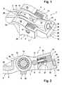
- FIG. 1
- in a three-dimensional view of the rocker arm and the invention
- FIG. 2
- a section along the longitudinal center plane of the finger lever.
Die Figuren offenbaren einen schaltbaren Schlepphebel 1 eines Ventiltriebs einer Brennkraftmaschine. Dieser besteht aus einem in Draufsicht U-ähnlichen, dünnwandigen Außenhebel 4, zwischen dessen Armen 2 ein balkenartiger Innenhebel 3 mit seinen Seitenwänden 19 aufgenommen ist. Die Hebel 3, 4 verlaufen auf einer gemeinsamen Achse 5 relativ verschwenkbeweglich zueinander. Die Achse 5 liegt im Bereich einer Quermittelebene des Schlepphebels 1.The figures disclose a switchable drag lever 1 of a valve train of an internal combustion engine. This consists of a U-like in plan view, thin-walled
Der Innenhebel 3 hat an einem Ende 8 an einer Unterseite 7 eine Anlage 9 für wenigstens ein Gaswechselventil. Am anderen Ende 10 hat der Innenhebel 3 an der Unterseite 7 eine Komplementärfläche 11 zur Lagerung auf einem Kopf eines Abstützelements. Gleichzeitig ist zu erkennen, dass oberhalb der Komplementärfläche 11 ein längs verlagerbarer Schieber als Koppelmittel 6 positioniert ist. Dieser kann über Hydraulikmittel in seine Koppelposition verlagert werden. Letzteres ist über einen direkten Kanal 27 aus dem Kopf des Abstützelements vor eine Innenstirn des Koppelmittels 6 leitbar. Für einen gewünschten Koppelfall wird das Koppelmittel 6 hydraulisch abschnittsweise aus dem Innenhebel 3 ausgefahren, wofür ein Querbalken 16 am anderen Ende 10, welcher die Arme 2 des Außenhebels 4 verbindet, an seiner Oberseite 18 eine Komplementärfläche 17 besitzt.The
Auf der Seite des einen Endes 8 hat der Außenhebel 4 nach der Achse 5 zwei Anlaufflächen 12 für respektive Großhubnocken. Diese sind hier als Gleitflächen ausgebildet. Der Innenhebel 3 besitzt in diesem Querbereich zwischen seinen Seitenwänden 19 eine drehbare und vorzugsweise wälzgelagerte Rolle, die als Anlauffläche 13 beispielsweise für einen Niedrighubnocken dient.On the side of the one
Es ist zu erkennen, dass der Innenhebel 3 mit seinem Abschnitt, welcher die Anlage 9 am einen Ende 8 hat, über Stirnseiten 15 des Außenhebels 4 hinaussteht. Der Außenhebel 4 ist somit unmittelbar nach seinen Anlaufflächen 12 "abgekürzt". Offenbart ist zudem, dass der Innenhebel 3 im Bereich des einen Endes 8 durch einen Quersteg 20 verbunden ist, welcher an seiner Unterseite die vorgenannte Anlage 9 besitzt.It can be seen that the
Wie Figur 1 zeigt, ist die Achse 5 mit zwei Lost-Motion-Federn 14 versehen, die hier als Drehschenkelfedern ausgebildet sind. Diese Federn 14 verlaufen axial zwischen den Armen 2 des Außenhebels 4 und den Armen 19 des Innenhebels 3. Zur Schaffung des entsprechenden Bauraums sind die Arme 2 des Außenhebels 4 in diesem Bereich kastenartig ausgeformt.As Figure 1 shows, the
Um eine fluchtende Lagezuordnung des Innenhebels 3 zum Außenhebel 4 bei Nockengrundkreisdurchlauf zu garantieren, werden zwei Vorschläge gemacht. Entweder steht am anderen Ende 10 von einem unteren Abschnitt 22 des Innenhebels 3 ein Ansatz 24 ab. Auf diesem kann der Querbalken 16 des Außenhebels 4 mit seiner Unterseite 25 zur Anlage kommen.In order to guarantee an aligned position assignment of the
Alternativ hierzu kann ein Querbalken 26 benutzt werden, der die Arme 2 des Außenhebels 4 in etwa im Bereich einer Quermittelebene des Schlepphebels 1, den Innenhebel 3 untergreifend, verbindet. Hierzu kann der Innenhebel 3 mit einem geeigneten Bereich seiner Unterseite 7 in Anlage auf einer Oberseite des Querbalkens 26 kommen.Alternatively, a
Wie beschreibungseinleitend dargelegt, ist die Achse 5, in Längsrichtung des Schlepphebels 1 gesehen, zwischen der Komplementärfläche 11 für das Abstützelement und den Anlaufflächen 12, 13 für die Hubnocken angeordnet. Somit wurde diese Achse 5, bezogen auf den beschreibungseinleitend zitierten Stand der Technik, deutlich weiter in Richtung zur Hebelmitte verlagert. Sie liegt jetzt deutlich näher am Schwenkpunkt des gesamten Schlepphebels 1 (Komplementärfläche 11). Hierdurch ist eine Reduzierung des Massenträgheitsmoments des gesamten Schlepphebels 1 um diesen Schwenkpunkt erzielbar, was zu einer Erhöhung der maximalen Drehzahl im gekoppelten Zustand des Schlepphebels 1 führen kann. Gleichzeitig ist auch im entkoppelten Zustand das Massenträgheitsmoment des Außenhebels 4 um die Achse 5 reduziert. Auch erfährt der Außenhebel 4 im Koppelzustand bei Nockenbeaufschlagung nicht mehr die relativ hohe Durchbiegung wie im beschreibungseinleitend zitierten Stand der Technik. Somit kann der Außenhebel 4 ggf. schwächer dimensioniert werden.As described in the introduction, the
- 1) Schlepphebel1) drag lever
- 2) Arm2) arm
- 3) Innenhebel3) Inner lever
- 4) Außenhebel4) outside lever
- 5) Achse5) axis
- 6) Koppelmittel6) Coupling agent
- 7) Unterseite7) bottom
- 8) Ende8) End
- 9) Anlage9) attachment
- 10)Ende10) End
- 11) Komplementärfläche11) Complementary surface
- 12)Anlauffläche12) stop face
- 13)Anlauffläche13) stop face
- 14) Lost-Motion-Feder14) Lost motion spring
- 15) Stirnseite15) front side
- 16)Querbalken16) crossbar
- 17)Komplementärfläche17) complementary surface
- 18)Oberseite18) top
- 19)Seitenwand19) side wall
- 20)Quersteg20) transverse web
- 21)Abschnitt21) section
- 22)Abschnitt22) section
- 23)Stirnfläche23) face
- 24)Ansatz24) approach
- 25) Unterseite25) bottom
- 26)Querbalken26) crossbar
- 27) Kanal27) channel
Claims (9)
Translated fromGermanApplications Claiming Priority (1)
| Application Number | Priority Date | Filing Date | Title |
|---|---|---|---|
| DE102005053596ADE102005053596A1 (en) | 2005-11-10 | 2005-11-10 | Switchable drag lever of a valve train of an internal combustion engine |
Publications (2)
| Publication Number | Publication Date |
|---|---|
| EP1785595A1true EP1785595A1 (en) | 2007-05-16 |
| EP1785595B1 EP1785595B1 (en) | 2008-06-25 |
Family
ID=37814343
Family Applications (1)
| Application Number | Title | Priority Date | Filing Date |
|---|---|---|---|
| EP06122627ANot-in-forceEP1785595B1 (en) | 2005-11-10 | 2006-10-20 | Switchable rocker arm of a valve train of an internal combustion engine |
Country Status (4)
| Country | Link |
|---|---|
| US (1) | US7377247B2 (en) |
| EP (1) | EP1785595B1 (en) |
| KR (1) | KR20070050368A (en) |
| DE (2) | DE102005053596A1 (en) |
Cited By (25)
| Publication number | Priority date | Publication date | Assignee | Title |
|---|---|---|---|---|
| WO2011116331A3 (en)* | 2010-03-19 | 2011-11-10 | Eaton Corporation | Switching rocker arm |
| EP2642094A1 (en) | 2012-03-20 | 2013-09-25 | MAN Diesel & Turbo SE | Switchable swing arm |
| WO2013156610A1 (en)* | 2012-04-19 | 2013-10-24 | Eaton Srl | A rocker arm |
| US8915225B2 (en) | 2010-03-19 | 2014-12-23 | Eaton Corporation | Rocker arm assembly and components therefor |
| US9016252B2 (en) | 2008-07-22 | 2015-04-28 | Eaton Corporation | System to diagnose variable valve actuation malfunctions by monitoring fluid pressure in a hydraulic lash adjuster gallery |
| US9038586B2 (en) | 2010-03-19 | 2015-05-26 | Eaton Corporation | Rocker assembly having improved durability |
| US9194261B2 (en) | 2011-03-18 | 2015-11-24 | Eaton Corporation | Custom VVA rocker arms for left hand and right hand orientations |
| US9194260B2 (en) | 2010-03-19 | 2015-11-24 | Eaton Corporation | Switching rocker arm |
| CN103328777B (en)* | 2011-02-10 | 2015-12-09 | 舍弗勒技术股份两合公司 | Intermediate lever |
| US9228454B2 (en) | 2010-03-19 | 2016-01-05 | Eaton Coporation | Systems, methods and devices for rocker arm position sensing |
| US9267396B2 (en) | 2010-03-19 | 2016-02-23 | Eaton Corporation | Rocker arm assembly and components therefor |
| USD750670S1 (en) | 2013-02-22 | 2016-03-01 | Eaton Corporation | Rocker arm |
| US9284859B2 (en) | 2010-03-19 | 2016-03-15 | Eaton Corporation | Systems, methods, and devices for valve stem position sensing |
| US9291075B2 (en) | 2008-07-22 | 2016-03-22 | Eaton Corporation | System to diagnose variable valve actuation malfunctions by monitoring fluid pressure in a control gallery |
| US9581058B2 (en) | 2010-08-13 | 2017-02-28 | Eaton Corporation | Development of a switching roller finger follower for cylinder deactivation in internal combustion engines |
| US9869211B2 (en) | 2014-03-03 | 2018-01-16 | Eaton Corporation | Valve actuating device and method of making same |
| US9874122B2 (en) | 2010-03-19 | 2018-01-23 | Eaton Corporation | Rocker assembly having improved durability |
| US9885258B2 (en) | 2010-03-19 | 2018-02-06 | Eaton Corporation | Latch interface for a valve actuating device |
| US9938865B2 (en) | 2008-07-22 | 2018-04-10 | Eaton Corporation | Development of a switching roller finger follower for cylinder deactivation in internal combustion engines |
| DE102017112468B3 (en) | 2017-06-07 | 2018-07-19 | Schaeffler Technologies AG & Co. KG | Hydraulic support element |
| DE102017204877A1 (en) | 2017-03-23 | 2018-09-27 | Bayerische Motoren Werke Aktiengesellschaft | Valve drive for an internal combustion engine and cylinder head |
| US10087790B2 (en) | 2009-07-22 | 2018-10-02 | Eaton Corporation | Cylinder head arrangement for variable valve actuation rocker arm assemblies |
| US10415439B2 (en) | 2008-07-22 | 2019-09-17 | Eaton Intelligent Power Limited | Development of a switching roller finger follower for cylinder deactivation in internal combustion engines |
| US11181013B2 (en) | 2009-07-22 | 2021-11-23 | Eaton Intelligent Power Limited | Cylinder head arrangement for variable valve actuation rocker arm assemblies |
| US11788439B2 (en) | 2010-03-19 | 2023-10-17 | Eaton Intelligent Power Limited | Development of a switching roller finger follower for cylinder deactivation in internal combustion engines |
Families Citing this family (27)
| Publication number | Priority date | Publication date | Assignee | Title |
|---|---|---|---|---|
| DE102004051422A1 (en)* | 2004-10-22 | 2006-05-24 | Schaeffler Kg | Switchable drag lever |
| KR100867842B1 (en)* | 2006-10-10 | 2008-11-10 | 현대자동차주식회사 | Variable Valve Lift Followers for Automotive |
| DE102007029465A1 (en)* | 2007-06-26 | 2009-01-08 | Schaeffler Kg | Switchable drag lever of a valve train of an internal combustion engine |
| US7761217B2 (en)* | 2008-03-04 | 2010-07-20 | Delphi Technologies, Inc. | Diagnostics for two-mode variable valve activation devices |
| WO2014134601A1 (en) | 2013-03-01 | 2014-09-04 | Eaton Corporation | Latch interface for a valve actuating device |
| DE102010011420A1 (en)* | 2009-03-19 | 2010-09-30 | Schaeffler Technologies Gmbh & Co. Kg | Switchable drag lever of a valve train of an internal combustion engine |
| DE102009019680A1 (en)* | 2009-04-30 | 2010-11-11 | Schaeffler Technologies Gmbh & Co. Kg | Valve train system |
| DE102010015719A1 (en)* | 2009-06-01 | 2010-12-30 | Schaeffler Technologies Gmbh & Co. Kg | Switchable drag lever for a valve train of an internal combustion engine |
| JP2011208631A (en)* | 2010-03-12 | 2011-10-20 | Nsk Ltd | Tappet roller bearing |
| KR101145638B1 (en)* | 2010-05-06 | 2012-07-11 | 현대자동차주식회사 | Variable valve lift apparatus |
| KR101209737B1 (en)* | 2010-10-22 | 2012-12-07 | 현대자동차주식회사 | Variable valve lift system |
| CN103518041A (en) | 2011-01-27 | 2014-01-15 | 史古德利集团公司 | Lost-motion variable valve actuation system with cam phaser |
| CA2825771A1 (en) | 2011-01-27 | 2012-08-02 | Scuderi Group, Inc. | Lost-motion variable valve actuation system with valve deactivation |
| JP2015506436A (en) | 2012-01-06 | 2015-03-02 | スクデリ グループ インコーポレイテッド | Lost motion variable valve actuation system |
| EP2971636A1 (en) | 2013-03-15 | 2016-01-20 | Scuderi Group, Inc. | Split-cycle engines with direct injection |
| KR20160057761A (en)* | 2014-11-14 | 2016-05-24 | 현대자동차주식회사 | Variable valve lift appratus |
| US9816409B2 (en) | 2014-12-09 | 2017-11-14 | Hyundai Motor Company | Variable valve lift apparatus |
| CN104696037A (en)* | 2015-03-18 | 2015-06-10 | 杭州新坐标科技股份有限公司 | Low inertia high strength roller rocker |
| USD791190S1 (en) | 2015-07-13 | 2017-07-04 | Eaton Corporation | Rocker arm assembly |
| USD833482S1 (en) | 2015-07-13 | 2018-11-13 | Eaton Corporation | Rocker arm |
| JP2018523058A (en) | 2015-08-05 | 2018-08-16 | イートン インテリジェント パワー リミテッド | Switching rocker arm for internal exhaust gas recirculation |
| USD830414S1 (en) | 2015-12-10 | 2018-10-09 | Eaton S.R.L. | Roller rocker arm of an engine |
| US10006322B2 (en) | 2016-04-26 | 2018-06-26 | Hyundai Motor Company | Variable valve lift apparatus |
| KR101855770B1 (en) | 2016-08-17 | 2018-05-09 | 현대자동차 주식회사 | Varible vavle duration apparatus |
| CN109923287A (en) | 2016-10-07 | 2019-06-21 | 伊顿智能动力有限公司 | Three-roller rocker arm with cantilevered roller and lost motion spring over valve or rocker pivot |
| CN213980897U (en) | 2018-02-23 | 2021-08-17 | 伊顿智能动力有限公司 | Switching roller finger follower |
| US10502102B1 (en)* | 2018-07-10 | 2019-12-10 | Schaeffler Technologies AG & Co. KG | Actuation arrangement for a switchable lever |
Citations (4)
| Publication number | Priority date | Publication date | Assignee | Title |
|---|---|---|---|---|
| DE10155825A1 (en)* | 2001-11-14 | 2003-05-22 | Ina Schaeffler Kg | Rocker arm used in a valve gear of an internal combustion engine comprises an outer lever having an inner lever positioned between its arms which pivot relative to each other |
| DE10310226A1 (en)* | 2003-03-08 | 2004-09-16 | Ina-Schaeffler Kg | Drag lever of a valve train of an internal combustion engine |
| DE10347329A1 (en)* | 2003-10-11 | 2005-05-04 | Ina Schaeffler Kg | Operating lever for a combustion engine valve drive has coupled inner and outer levers and can be changed for different lift actions for at least one gas exchange valve |
| WO2005093224A1 (en)* | 2004-03-03 | 2005-10-06 | Timken Us Corporation | Switching finger follower assembly |
Family Cites Families (7)
| Publication number | Priority date | Publication date | Assignee | Title |
|---|---|---|---|---|
| DE2753197A1 (en)* | 1976-12-15 | 1978-06-22 | Eaton Corp | VALVE CONTROL DEVICE |
| DE10137490A1 (en)* | 2001-07-31 | 2003-02-13 | Ina Schaeffler Kg | Valve control device for internal combustion engine has a multi-part drag lever with primary lever and a secondary lever on each side of same and actuated by second cam |
| US6668779B2 (en)* | 2002-05-08 | 2003-12-30 | Delphi Technologies, Inc. | Two-step finger follower rocker arm assembly |
| DE10257705A1 (en)* | 2002-12-11 | 2004-06-24 | Ina-Schaeffler Kg | Valve lever for valve train of internal combustion engine has outer lever enclosing inner lever with arms and swiveled away from it when decoupled |
| DE10316189A1 (en)* | 2003-04-09 | 2004-10-28 | Ina-Schaeffler Kg | Tow lever for a combustion engine valve drive has outer and inner levers connected through an axle across the inner lever |
| ATE435359T1 (en)* | 2004-02-25 | 2009-07-15 | Delphi Tech Inc | HYDRAULIC VALVE CLEARANCE COMPENSATOR |
| DE102005048984A1 (en)* | 2005-10-13 | 2007-04-19 | Schaeffler Kg | Switchable drag lever |
- 2005
- 2005-11-10DEDE102005053596Apatent/DE102005053596A1/ennot_activeWithdrawn
- 2006
- 2006-10-20EPEP06122627Apatent/EP1785595B1/ennot_activeNot-in-force
- 2006-10-20DEDE502006000981Tpatent/DE502006000981D1/enactiveActive
- 2006-11-09KRKR1020060110234Apatent/KR20070050368A/ennot_activeCeased
- 2006-11-09USUS11/595,257patent/US7377247B2/ennot_activeExpired - Fee Related
Patent Citations (4)
| Publication number | Priority date | Publication date | Assignee | Title |
|---|---|---|---|---|
| DE10155825A1 (en)* | 2001-11-14 | 2003-05-22 | Ina Schaeffler Kg | Rocker arm used in a valve gear of an internal combustion engine comprises an outer lever having an inner lever positioned between its arms which pivot relative to each other |
| DE10310226A1 (en)* | 2003-03-08 | 2004-09-16 | Ina-Schaeffler Kg | Drag lever of a valve train of an internal combustion engine |
| DE10347329A1 (en)* | 2003-10-11 | 2005-05-04 | Ina Schaeffler Kg | Operating lever for a combustion engine valve drive has coupled inner and outer levers and can be changed for different lift actions for at least one gas exchange valve |
| WO2005093224A1 (en)* | 2004-03-03 | 2005-10-06 | Timken Us Corporation | Switching finger follower assembly |
Cited By (52)
| Publication number | Priority date | Publication date | Assignee | Title |
|---|---|---|---|---|
| US9016252B2 (en) | 2008-07-22 | 2015-04-28 | Eaton Corporation | System to diagnose variable valve actuation malfunctions by monitoring fluid pressure in a hydraulic lash adjuster gallery |
| US10415439B2 (en) | 2008-07-22 | 2019-09-17 | Eaton Intelligent Power Limited | Development of a switching roller finger follower for cylinder deactivation in internal combustion engines |
| US9964005B2 (en) | 2008-07-22 | 2018-05-08 | Eaton Corporation | Method for diagnosing variable valve actuation malfunctions by monitoring fluid pressure in a control gallery |
| US9938865B2 (en) | 2008-07-22 | 2018-04-10 | Eaton Corporation | Development of a switching roller finger follower for cylinder deactivation in internal combustion engines |
| US9644503B2 (en) | 2008-07-22 | 2017-05-09 | Eaton Corporation | System to diagnose variable valve actuation malfunctions by monitoring fluid pressure in a hydraulic lash adjuster gallery |
| US9291075B2 (en) | 2008-07-22 | 2016-03-22 | Eaton Corporation | System to diagnose variable valve actuation malfunctions by monitoring fluid pressure in a control gallery |
| US11181013B2 (en) | 2009-07-22 | 2021-11-23 | Eaton Intelligent Power Limited | Cylinder head arrangement for variable valve actuation rocker arm assemblies |
| US10087790B2 (en) | 2009-07-22 | 2018-10-02 | Eaton Corporation | Cylinder head arrangement for variable valve actuation rocker arm assemblies |
| US9708942B2 (en) | 2010-03-19 | 2017-07-18 | Eaton Corporation | Rocker arm assembly and components therefor |
| US10119429B2 (en) | 2010-03-19 | 2018-11-06 | Eaton Corporation | Systems, methods, and devices for valve stem position sensing |
| US8915225B2 (en) | 2010-03-19 | 2014-12-23 | Eaton Corporation | Rocker arm assembly and components therefor |
| US9038586B2 (en) | 2010-03-19 | 2015-05-26 | Eaton Corporation | Rocker assembly having improved durability |
| US11788439B2 (en) | 2010-03-19 | 2023-10-17 | Eaton Intelligent Power Limited | Development of a switching roller finger follower for cylinder deactivation in internal combustion engines |
| US9194260B2 (en) | 2010-03-19 | 2015-11-24 | Eaton Corporation | Switching rocker arm |
| CN103221645B (en)* | 2010-03-19 | 2015-11-25 | 伊顿公司 | Conversion rocking arm |
| US11530630B2 (en) | 2010-03-19 | 2022-12-20 | Eaton Intelligent Power Limited | Systems, methods, and devices for rocker arm position sensing |
| US9228454B2 (en) | 2010-03-19 | 2016-01-05 | Eaton Coporation | Systems, methods and devices for rocker arm position sensing |
| US9267396B2 (en) | 2010-03-19 | 2016-02-23 | Eaton Corporation | Rocker arm assembly and components therefor |
| WO2011116329A3 (en)* | 2010-03-19 | 2011-11-10 | Eaton Corporation | Switching rocker arm |
| US9284859B2 (en) | 2010-03-19 | 2016-03-15 | Eaton Corporation | Systems, methods, and devices for valve stem position sensing |
| US8752513B2 (en) | 2010-03-19 | 2014-06-17 | Eaton Corporation | Switching rocker arm |
| US11085338B2 (en) | 2010-03-19 | 2021-08-10 | Eaton Intelligent Power Limited | Systems, methods and devices for rocker arm position sensing |
| US10890086B2 (en) | 2010-03-19 | 2021-01-12 | Eaton Intelligent Power Limited | Latch interface for a valve actuating device |
| US8726862B2 (en) | 2010-03-19 | 2014-05-20 | Eaton Corporation | Switching rocker arm |
| US10570786B2 (en) | 2010-03-19 | 2020-02-25 | Eaton Intelligent Power Limited | Rocker assembly having improved durability |
| US9702279B2 (en) | 2010-03-19 | 2017-07-11 | Eaton Corporation | Sensing and control of a variable valve actuation system |
| WO2011116331A3 (en)* | 2010-03-19 | 2011-11-10 | Eaton Corporation | Switching rocker arm |
| US9726052B2 (en) | 2010-03-19 | 2017-08-08 | Eaton Corporation | Rocker arm assembly and components therefor |
| US9765657B2 (en) | 2010-03-19 | 2017-09-19 | Eaton Corporation | System, method and device for rocker arm position sensing |
| CN103221645A (en)* | 2010-03-19 | 2013-07-24 | 伊顿公司 | Switching rocker arm |
| US9874122B2 (en) | 2010-03-19 | 2018-01-23 | Eaton Corporation | Rocker assembly having improved durability |
| US9885258B2 (en) | 2010-03-19 | 2018-02-06 | Eaton Corporation | Latch interface for a valve actuating device |
| US9915180B2 (en) | 2010-03-19 | 2018-03-13 | Eaton Corporation | Latch interface for a valve actuating device |
| US10180087B2 (en) | 2010-03-19 | 2019-01-15 | Eaton Corporation | Rocker arm assembly and components therefor |
| US8985074B2 (en) | 2010-03-19 | 2015-03-24 | Eaton Corporation | Sensing and control of a variable valve actuation system |
| US9581058B2 (en) | 2010-08-13 | 2017-02-28 | Eaton Corporation | Development of a switching roller finger follower for cylinder deactivation in internal combustion engines |
| CN103328777B (en)* | 2011-02-10 | 2015-12-09 | 舍弗勒技术股份两合公司 | Intermediate lever |
| US10329970B2 (en) | 2011-03-18 | 2019-06-25 | Eaton Corporation | Custom VVA rocker arms for left hand and right hand orientations |
| US9194261B2 (en) | 2011-03-18 | 2015-11-24 | Eaton Corporation | Custom VVA rocker arms for left hand and right hand orientations |
| US9664075B2 (en) | 2011-03-18 | 2017-05-30 | Eaton Corporation | Custom VVA rocker arms for left hand and right hand orientations |
| DE102012204367A1 (en) | 2012-03-20 | 2013-09-26 | Man Diesel & Turbo Se | Switchable rocker arm |
| EP2642094A1 (en) | 2012-03-20 | 2013-09-25 | MAN Diesel & Turbo SE | Switchable swing arm |
| WO2013156610A1 (en)* | 2012-04-19 | 2013-10-24 | Eaton Srl | A rocker arm |
| US10196943B2 (en) | 2012-04-19 | 2019-02-05 | Eaton Intelligent Power Limited | Valve train assembly |
| US9470116B2 (en) | 2012-04-19 | 2016-10-18 | Eaton Srl | Rocker arm |
| USD750670S1 (en) | 2013-02-22 | 2016-03-01 | Eaton Corporation | Rocker arm |
| US9869211B2 (en) | 2014-03-03 | 2018-01-16 | Eaton Corporation | Valve actuating device and method of making same |
| US9995183B2 (en) | 2014-03-03 | 2018-06-12 | Eaton Corporation | Valve actuating device and method of making same |
| DE102017204877A1 (en) | 2017-03-23 | 2018-09-27 | Bayerische Motoren Werke Aktiengesellschaft | Valve drive for an internal combustion engine and cylinder head |
| WO2018224074A1 (en) | 2017-06-07 | 2018-12-13 | Schaeffler Technologies AG & Co. KG | Hydraulic support element |
| US11459915B2 (en) | 2017-06-07 | 2022-10-04 | Schaeffler Technologies AG & Co. KG | Hydraulic support element |
| DE102017112468B3 (en) | 2017-06-07 | 2018-07-19 | Schaeffler Technologies AG & Co. KG | Hydraulic support element |
Also Published As
| Publication number | Publication date |
|---|---|
| EP1785595B1 (en) | 2008-06-25 |
| DE502006000981D1 (en) | 2008-08-07 |
| US20070101958A1 (en) | 2007-05-10 |
| KR20070050368A (en) | 2007-05-15 |
| US7377247B2 (en) | 2008-05-27 |
| DE102005053596A1 (en) | 2007-05-16 |
Similar Documents
| Publication | Publication Date | Title |
|---|---|---|
| EP1785595B1 (en) | Switchable rocker arm of a valve train of an internal combustion engine | |
| DE102005037052B4 (en) | Switchable drag lever of a valve train of an internal combustion engine | |
| EP2013450B1 (en) | Switchable cam follower of a valve train assembly of an internal combustion engine | |
| EP1616082B1 (en) | Rocker arm of a valve gear of a combustion engine | |
| DE10155800A1 (en) | Rocker arm used in a valve gear of an internal combustion engine has an fork-shaped outer lever, and an inner lever having a running surface for the cam formed as a rotating roller | |
| DE102004007766A1 (en) | Cam follower for valve gear of internal combustion engine has arms of outer lever connected to transverse beam, and slide interconnecting outer and inner levers is movable in longitudinal bore to act on underside of transverse beam | |
| DE102010015719A1 (en) | Switchable drag lever for a valve train of an internal combustion engine | |
| WO2007017027A1 (en) | Switchable cam follower of a valve train of an internal combustion engine | |
| WO2007039414A1 (en) | Asymmetrical rocker arm for a valve gear of an internal combustion engine | |
| WO2005005788A1 (en) | Method for production of an outer lever for a switchable cam follower | |
| DE102010011420A1 (en) | Switchable drag lever of a valve train of an internal combustion engine | |
| DE102009035531A1 (en) | Switchable drag lever | |
| DE10226821A1 (en) | Rocker arm of a valve train of an internal combustion engine | |
| DE10155825A1 (en) | Rocker arm used in a valve gear of an internal combustion engine comprises an outer lever having an inner lever positioned between its arms which pivot relative to each other | |
| DE102010011421A1 (en) | Switchable drag lever of a valve train of an internal combustion engine | |
| DE102005048984A1 (en) | Switchable drag lever | |
| DE102009056367A1 (en) | Component for valve gear of internal-combustion engine, has detachable cam follower, which is connected with supporting element by pivoted joint | |
| DE19811658B4 (en) | Pivoting cam follower of a valve train of an internal combustion engine | |
| DE102009041368A1 (en) | Assembly for valve train of internal combustion engine, comprises switching cam lever, which is fastened at end of head of supporting element by swiveling joint | |
| WO2014135159A1 (en) | Cam follower for a valve train of an internal combustion engine | |
| WO2003042510A1 (en) | Drag lever of a valve mechanism in an internal combustion engine | |
| DE102005037051A1 (en) | Switchable drag lever of a valve train of an internal combustion engine | |
| DE10006016B4 (en) | Variable valve drive for load control of a spark-ignited internal combustion engine | |
| DE102007020108A1 (en) | Cylinder valve cam drive, for an internal combustion motor, has a single support for the cam follower between it and the cylinder head | |
| DE10308995B4 (en) | Drag lever of a valve train of an internal combustion engine |
Legal Events
| Date | Code | Title | Description |
|---|---|---|---|
| PUAI | Public reference made under article 153(3) epc to a published international application that has entered the european phase | Free format text:ORIGINAL CODE: 0009012 | |
| AK | Designated contracting states | Kind code of ref document:A1 Designated state(s):AT BE BG CH CY CZ DE DK EE ES FI FR GB GR HU IE IS IT LI LT LU LV MC NL PL PT RO SE SI SK TR | |
| AX | Request for extension of the european patent | Extension state:AL BA HR MK YU | |
| 17P | Request for examination filed | Effective date:20070412 | |
| 17Q | First examination report despatched | Effective date:20070621 | |
| GRAP | Despatch of communication of intention to grant a patent | Free format text:ORIGINAL CODE: EPIDOSNIGR1 | |
| AKX | Designation fees paid | Designated state(s):DE FR GB IT | |
| GRAS | Grant fee paid | Free format text:ORIGINAL CODE: EPIDOSNIGR3 | |
| GRAA | (expected) grant | Free format text:ORIGINAL CODE: 0009210 | |
| AK | Designated contracting states | Kind code of ref document:B1 Designated state(s):DE FR GB IT | |
| REG | Reference to a national code | Ref country code:GB Ref legal event code:FG4D Free format text:NOT ENGLISH | |
| REF | Corresponds to: | Ref document number:502006000981 Country of ref document:DE Date of ref document:20080807 Kind code of ref document:P | |
| PLBE | No opposition filed within time limit | Free format text:ORIGINAL CODE: 0009261 | |
| STAA | Information on the status of an ep patent application or granted ep patent | Free format text:STATUS: NO OPPOSITION FILED WITHIN TIME LIMIT | |
| 26N | No opposition filed | Effective date:20090326 | |
| PGFP | Annual fee paid to national office [announced via postgrant information from national office to epo] | Ref country code:GB Payment date:20101029 Year of fee payment:5 Ref country code:IT Payment date:20101025 Year of fee payment:5 | |
| REG | Reference to a national code | Ref country code:GB Ref legal event code:732E Free format text:REGISTERED BETWEEN 20110407 AND 20110413 | |
| PGFP | Annual fee paid to national office [announced via postgrant information from national office to epo] | Ref country code:FR Payment date:20111115 Year of fee payment:6 | |
| REG | Reference to a national code | Ref country code:DE Ref legal event code:R081 Ref document number:502006000981 Country of ref document:DE Owner name:SCHAEFFLER TECHNOLOGIES AG & CO. KG, DE Free format text:FORMER OWNER: SCHAEFFLER TECHNOLOGIES GMBH & CO. KG, 91074 HERZOGENAURACH, DE Effective date:20120828 Ref country code:DE Ref legal event code:R081 Ref document number:502006000981 Country of ref document:DE Owner name:SCHAEFFLER TECHNOLOGIES GMBH & CO. KG, DE Free format text:FORMER OWNER: SCHAEFFLER TECHNOLOGIES GMBH & CO. KG, 91074 HERZOGENAURACH, DE Effective date:20120828 | |
| GBPC | Gb: european patent ceased through non-payment of renewal fee | Effective date:20121020 | |
| REG | Reference to a national code | Ref country code:FR Ref legal event code:ST Effective date:20130628 | |
| PG25 | Lapsed in a contracting state [announced via postgrant information from national office to epo] | Ref country code:GB Free format text:LAPSE BECAUSE OF NON-PAYMENT OF DUE FEES Effective date:20121020 | |
| PG25 | Lapsed in a contracting state [announced via postgrant information from national office to epo] | Ref country code:IT Free format text:LAPSE BECAUSE OF NON-PAYMENT OF DUE FEES Effective date:20121020 Ref country code:FR Free format text:LAPSE BECAUSE OF NON-PAYMENT OF DUE FEES Effective date:20121031 | |
| REG | Reference to a national code | Ref country code:DE Ref legal event code:R081 Ref document number:502006000981 Country of ref document:DE Owner name:SCHAEFFLER TECHNOLOGIES AG & CO. KG, DE Free format text:FORMER OWNER: SCHAEFFLER TECHNOLOGIES AG & CO. KG, 91074 HERZOGENAURACH, DE Effective date:20140218 Ref country code:DE Ref legal event code:R081 Ref document number:502006000981 Country of ref document:DE Owner name:SCHAEFFLER TECHNOLOGIES GMBH & CO. KG, DE Free format text:FORMER OWNER: SCHAEFFLER TECHNOLOGIES AG & CO. KG, 91074 HERZOGENAURACH, DE Effective date:20140218 | |
| REG | Reference to a national code | Ref country code:DE Ref legal event code:R081 Ref document number:502006000981 Country of ref document:DE Owner name:SCHAEFFLER TECHNOLOGIES AG & CO. KG, DE Free format text:FORMER OWNER: SCHAEFFLER TECHNOLOGIES GMBH & CO. KG, 91074 HERZOGENAURACH, DE Effective date:20150213 | |
| PGFP | Annual fee paid to national office [announced via postgrant information from national office to epo] | Ref country code:DE Payment date:20171229 Year of fee payment:12 | |
| REG | Reference to a national code | Ref country code:DE Ref legal event code:R119 Ref document number:502006000981 Country of ref document:DE | |
| PG25 | Lapsed in a contracting state [announced via postgrant information from national office to epo] | Ref country code:DE Free format text:LAPSE BECAUSE OF NON-PAYMENT OF DUE FEES Effective date:20190501 | |
| P01 | Opt-out of the competence of the unified patent court (upc) registered | Effective date:20230522 |