EP1785103A1 - Apparatus for anterior cruciate ligament (ACL) reconstruction using rotary drill cutter to form retrograde sockets - Google Patents
Apparatus for anterior cruciate ligament (ACL) reconstruction using rotary drill cutter to form retrograde socketsDownload PDFInfo
- Publication number
- EP1785103A1 EP1785103A1EP06023424AEP06023424AEP1785103A1EP 1785103 A1EP1785103 A1EP 1785103A1EP 06023424 AEP06023424 AEP 06023424AEP 06023424 AEP06023424 AEP 06023424AEP 1785103 A1EP1785103 A1EP 1785103A1
- Authority
- EP
- European Patent Office
- Prior art keywords
- retrograde
- drill
- guide
- rotary drill
- pin
- Prior art date
- Legal status (The legal status is an assumption and is not a legal conclusion. Google has not performed a legal analysis and makes no representation as to the accuracy of the status listed.)
- Granted
Links
- 210000001264anterior cruciate ligamentAnatomy0.000titleabstractdescription20
- 210000000988bone and boneAnatomy0.000claimsabstractdescription26
- 230000036346tooth eruptionEffects0.000claimsabstractdescription6
- 238000005553drillingMethods0.000claimsdescription25
- 238000003780insertionMethods0.000abstractdescription19
- 230000037431insertionEffects0.000abstractdescription19
- 210000002303tibiaAnatomy0.000abstractdescription11
- 230000015572biosynthetic processEffects0.000description17
- 238000000034methodMethods0.000description13
- 210000000689upper legAnatomy0.000description9
- 210000003127kneeAnatomy0.000description4
- 210000000629knee jointAnatomy0.000description4
- JTIGKVIOEQASGT-UHFFFAOYSA-NproquazoneChemical compoundN=1C(=O)N(C(C)C)C2=CC(C)=CC=C2C=1C1=CC=CC=C1JTIGKVIOEQASGT-UHFFFAOYSA-N0.000description4
- 238000009434installationMethods0.000description3
- 239000000463materialSubstances0.000description2
- 238000001356surgical procedureMethods0.000description2
- 206010064211Bone fragmentationDiseases0.000description1
- 0CC1C*CC1Chemical compoundCC1C*CC10.000description1
- RTAQQCXQSZGOHL-UHFFFAOYSA-NTitaniumChemical compound[Ti]RTAQQCXQSZGOHL-UHFFFAOYSA-N0.000description1
- 239000002131composite materialSubstances0.000description1
- 210000004349growth plateAnatomy0.000description1
- 238000003306harvestingMethods0.000description1
- 210000003041ligamentAnatomy0.000description1
- 238000012986modificationMethods0.000description1
- 230000004048modificationEffects0.000description1
- 230000010076replicationEffects0.000description1
- 210000004872soft tissueAnatomy0.000description1
- 238000006467substitution reactionMethods0.000description1
- 210000002435tendonAnatomy0.000description1
- 229910052719titaniumInorganic materials0.000description1
- 239000010936titaniumSubstances0.000description1
- 230000000007visual effectEffects0.000description1
Images


Classifications
- A—HUMAN NECESSITIES
- A61—MEDICAL OR VETERINARY SCIENCE; HYGIENE
- A61B—DIAGNOSIS; SURGERY; IDENTIFICATION
- A61B17/00—Surgical instruments, devices or methods
- A61B17/00234—Surgical instruments, devices or methods for minimally invasive surgery
- A—HUMAN NECESSITIES
- A61—MEDICAL OR VETERINARY SCIENCE; HYGIENE
- A61B—DIAGNOSIS; SURGERY; IDENTIFICATION
- A61B17/00—Surgical instruments, devices or methods
- A61B17/04—Surgical instruments, devices or methods for suturing wounds; Holders or packages for needles or suture materials
- A61B17/0401—Suture anchors, buttons or pledgets, i.e. means for attaching sutures to bone, cartilage or soft tissue; Instruments for applying or removing suture anchors
- A—HUMAN NECESSITIES
- A61—MEDICAL OR VETERINARY SCIENCE; HYGIENE
- A61B—DIAGNOSIS; SURGERY; IDENTIFICATION
- A61B17/00—Surgical instruments, devices or methods
- A61B17/16—Instruments for performing osteoclasis; Drills or chisels for bones; Trepans
- A61B17/1613—Component parts
- A61B17/1615—Drill bits, i.e. rotating tools extending from a handpiece to contact the worked material
- A61B17/1617—Drill bits, i.e. rotating tools extending from a handpiece to contact the worked material with mobile or detachable parts
- A—HUMAN NECESSITIES
- A61—MEDICAL OR VETERINARY SCIENCE; HYGIENE
- A61B—DIAGNOSIS; SURGERY; IDENTIFICATION
- A61B17/00—Surgical instruments, devices or methods
- A61B17/16—Instruments for performing osteoclasis; Drills or chisels for bones; Trepans
- A61B17/1662—Instruments for performing osteoclasis; Drills or chisels for bones; Trepans for particular parts of the body
- A61B17/1675—Instruments for performing osteoclasis; Drills or chisels for bones; Trepans for particular parts of the body for the knee
- A—HUMAN NECESSITIES
- A61—MEDICAL OR VETERINARY SCIENCE; HYGIENE
- A61B—DIAGNOSIS; SURGERY; IDENTIFICATION
- A61B17/00—Surgical instruments, devices or methods
- A61B17/16—Instruments for performing osteoclasis; Drills or chisels for bones; Trepans
- A61B17/17—Guides or aligning means for drills, mills, pins or wires
- A61B17/1714—Guides or aligning means for drills, mills, pins or wires for applying tendons or ligaments
- A—HUMAN NECESSITIES
- A61—MEDICAL OR VETERINARY SCIENCE; HYGIENE
- A61B—DIAGNOSIS; SURGERY; IDENTIFICATION
- A61B17/00—Surgical instruments, devices or methods
- A61B17/16—Instruments for performing osteoclasis; Drills or chisels for bones; Trepans
- A61B17/17—Guides or aligning means for drills, mills, pins or wires
- A61B17/1739—Guides or aligning means for drills, mills, pins or wires specially adapted for particular parts of the body
- A61B17/1764—Guides or aligning means for drills, mills, pins or wires specially adapted for particular parts of the body for the knee
- A—HUMAN NECESSITIES
- A61—MEDICAL OR VETERINARY SCIENCE; HYGIENE
- A61B—DIAGNOSIS; SURGERY; IDENTIFICATION
- A61B17/00—Surgical instruments, devices or methods
- A61B17/32—Surgical cutting instruments
- A61B17/320016—Endoscopic cutting instruments, e.g. arthroscopes, resectoscopes
- A61B17/32002—Endoscopic cutting instruments, e.g. arthroscopes, resectoscopes with continuously rotating, oscillating or reciprocating cutting instruments
- A—HUMAN NECESSITIES
- A61—MEDICAL OR VETERINARY SCIENCE; HYGIENE
- A61B—DIAGNOSIS; SURGERY; IDENTIFICATION
- A61B17/00—Surgical instruments, devices or methods
- A61B17/04—Surgical instruments, devices or methods for suturing wounds; Holders or packages for needles or suture materials
- A61B17/0485—Devices or means, e.g. loops, for capturing the suture thread and threading it through an opening of a suturing instrument or needle eyelet
- A—HUMAN NECESSITIES
- A61—MEDICAL OR VETERINARY SCIENCE; HYGIENE
- A61B—DIAGNOSIS; SURGERY; IDENTIFICATION
- A61B17/00—Surgical instruments, devices or methods
- A61B17/04—Surgical instruments, devices or methods for suturing wounds; Holders or packages for needles or suture materials
- A61B17/0401—Suture anchors, buttons or pledgets, i.e. means for attaching sutures to bone, cartilage or soft tissue; Instruments for applying or removing suture anchors
- A61B2017/0404—Buttons
- A—HUMAN NECESSITIES
- A61—MEDICAL OR VETERINARY SCIENCE; HYGIENE
- A61B—DIAGNOSIS; SURGERY; IDENTIFICATION
- A61B17/00—Surgical instruments, devices or methods
- A61B17/32—Surgical cutting instruments
- A61B17/320016—Endoscopic cutting instruments, e.g. arthroscopes, resectoscopes
- A61B17/32002—Endoscopic cutting instruments, e.g. arthroscopes, resectoscopes with continuously rotating, oscillating or reciprocating cutting instruments
- A61B2017/320032—Details of the rotating or oscillating shaft, e.g. using a flexible shaft
- A—HUMAN NECESSITIES
- A61—MEDICAL OR VETERINARY SCIENCE; HYGIENE
- A61B—DIAGNOSIS; SURGERY; IDENTIFICATION
- A61B90/00—Instruments, implements or accessories specially adapted for surgery or diagnosis and not covered by any of the groups A61B1/00 - A61B50/00, e.g. for luxation treatment or for protecting wound edges
- A61B90/06—Measuring instruments not otherwise provided for
- A61B2090/062—Measuring instruments not otherwise provided for penetration depth
Definitions
- the present inventionrelates to the field of surgery and, more particularly, to methods of reconstructive knee surgery.
- ACLanterior cruciate ligament
- U.S. Pat. No. 5,603,716discloses a technique for ACL reconstruction that avoids the above-noted problem by forming sockets in both the femur and the tibia using a coring bone harvester. The harvester is impacted into bone to a desired depth so that bone material collects as a bone core within the harvester tube. The bone core is extracted from the bone socket using a simultaneous twisting and pulling motion. Such harvesting of bone cores in the joint is technically difficult.
- a minimally invasive method of ACL reconstruction, and related instrumentationthat provides drilling of femoral and tibial sockets or tunnels independently of one another and minimizes incisions of distal cortices and reduces intraarticular bone fragmentation of tunnel rims.
- the present inventionovercomes the disadvantages of the prior art and fulfills the needs noted above by providing techniques and apparatus for creating bone sockets by drilling in a retrograde manner.
- the present inventionadvantageously utilizes a preloaded retrograde rotary drill cutter that provides exact visual replication of tunnel or socket diameter prior to drilling both the tibial and femoral sockets.
- the present inventionprovides a method for ACL reconstruction which includes the steps of introducing a guide having a rotary drill cutter threadably engaged on a distal end thereof into a joint through a portal, introducing a pin having a threaded distal end into the joint, inserting the threaded distal end of the pin into a correspondingly threaded cannulation in the rotary drill cutter, engaging the rotary drill cutter with the threaded distal end of the pin and simultaneously disengaging the rotary drill cutter from the guide by rotating the pin, and drilling into the bone to create the socket by rotating the rotary dull cutter and moving the rotary drill cutter in a retrograde manner using the pin.
- the present inventionalso includes a system for carrying out the above method, including a rotary drill cutter comprising a cylindrically shaped body provided with a threaded cannulation and radially outward cutting teeth for retrograde drilling of a socket in bone, a guide comprising a threaded post for threadably engaging and mounting the rotary drill cutter, and a drill pin having a threaded distal end corresponding to the threaded cannulation of the rotary drill cutter, for threadably engaging the rotary drill cutter.
- a rotary drill cuttercomprising a cylindrically shaped body provided with a threaded cannulation and radially outward cutting teeth for retrograde drilling of a socket in bone
- a guidecomprising a threaded post for threadably engaging and mounting the rotary drill cutter
- a drill pinhaving a threaded distal end corresponding to the threaded cannulation of the rotary drill cutter, for threadably engaging the rotary drill cutter.
- the systemis designed so that the rotary drill cutter is transferred from the guide to the drill pin by advancing the drill pin into the cannulation of the rotary drill cutter and rotating the drill pin in a first direction to threadably engage the drill pin with the rotary drill cutter mounted on the guide, and simultaneously threadably disengage the rotary drill cutter from the guide.
- the present inventionprovides techniques for forming femoral and tibial bone sockets in a retrograde manner during ligament reconstruction, for example, anterior cruciate ligament (ACL) reconstruction.
- the present inventionalso provides methods of graft insertion and fixation employed in connection with the femoral and tibial sockets of the present invention.
- FIGS. 1-2illustrate a retrograde rotary drill cutter 10 ( FIGS. 1A-1C ) which is adapted to be threadingly engaged with a cannulated retrograde drill pin 50 ( FIGS. 2A-2C ).
- the retrograde rotary drill cutter 10features a cylindrical body 11 having a plurality of cutting teeth 12 radiating symmetrically.
- a cannulation 13 through body 11is provided with internal screw threads 14.
- Cutting teeth 12have edges extending radially from cannulation 13 on a proximal cutting face 15, seen in plan view in FIG. 1A.
- the edges of cutting teeth 12continue axially along the side of the retrograde rotary drill cutter 10, which is oriented orthogonally to proximal cutting face 15.
- the edgesend at a smooth, rounded distal end 16 of retrograde rotary drill cutter 10.
- Retrograde rotary drill cutter 10is provided in a selected diameter corresponding to graft size as discussed further below.
- retrograde drill pin 50features a fluted region 51 formed on distal end 52 of cannulated body 53, as shown in detail in FIG. 2B.
- Cannulated body 53has a proximal end 54.
- the cannulated body 53is provided with screw threads 55 at distal end 52.
- the screw threads 55are fashioned to engage corresponding threads 14 of retrograde rotary drill cutter 10. Accordingly, the outer diameter of threaded region 55 closely approximates the diameter of cannula 13 of the retrograde rotary drill cutter 10, to allow secure engagement of the outer threaded region 55 with the inner threads 14 of retrograde rotary drill cutter 10.
- Retrograde drill pin 50features visible calibrated depth markings 56 lased onto the cannulated body 53. Between threads 55 and depth markings 56, a shoulder 57 is formed to provide a stop where threads 55 end.
- the lumen of cannulated body 53accepts a trocar 58 having a pointed tip 59. When the trocar is removed, a strand can be passed through the lumen of the cannulated body 53, as described below in greater detail.
- the proximal end 54 of cannulated body 53is configured for chucking into a rotary driver (not shown).
- Retrograde drill pin 50includes a setscrew collar 62 for securing the trocar 58 in the cannulated body 53.
- drill guide C-ring 70features visible calibrated angular markings 70" circumferentially lased onto the body (not shown).
- a groove (not shown) near one end of the drill guide C-ring 70is provided to secure a retrograde drill guide sleeve 71.
- a holding member 72" movable along the circumference of the drill guide C-ring 70is provided to secure a tibial guide 72 or a femoral guide 83.
- the holding member 72"facilitates angular adjustment of the tibial guide 72 or the femoral guide 83 relative to the retrograde drill guide sleeve 71.
- the tibial guide 72 or the femoral guide 83is provided with an insertion post 74 to allow secure engagement of the retrograde rotary drill cutter 10.
- FIGS. 4-12illustrate a schematic anterior view of a knee in which ACL reconstruction is performed according to the present invention.
- a tibial socket 81(shown completed in FIGS. 10-12 ) is formed in a tibia 75.
- the appropriate diameter retrograde rotary drill cutter 10is threaded onto the insertion post 74 of the tibial guide 72.
- the tibial guide 72is inserted through the anteromedial portal (not shown) and the retrograde rotary drill cutter 10 is placed on the anatomical origin of the ACL tibial insertion.
- the retrograde drill pin 50is adjusted to an appropriate angle, to avoid existing tunnels and fixation hardware, for insertion onto the tibia 75.
- the retrograde drill guide sleeve 71is inserted into the tibia 75 through a small stab incision on the tibia 75.
- the retrograde drill pin 50is drilled through the tibia, in a forward direction, to create pin hole 78 of a given diameter, for example 3mm, as shown in FIG. 5.
- the retrograde drill pin 50is drilled through the tibia 75 until contact is made with the retrograde rotary drill cutter 10 under arthroscopic control, as shown in FIG. 6.
- the reverse threads on the insertion post 74 of the tibial guide 72facilitate simultaneous disengagement of the retrograde rotary drill cutter 10 from the insertion post 74 onto the retrograde drill pin 50.
- the retrograde drill pin 50is rotated with a power driver (not shown) and retracted (retrograde) to cut through the tibial joint surface.
- the drill depth grommet 80 on the retrograde drill pin 50is advanced to the end of the retrograde drill guide sleeve 71 for socket depth assessment during drilling.
- the retrograde drill pin 50is retracted to facilitate retrograde drilling of the tibial joint surface and into the tibia 75 to create a tibial socket 81.
- a desired depth D 1preferably 25 mm., is obtained by reading the markings 80" on the retrograde drill pin 50, recorded relative to the skin tibial surface prior to and during socket formation.
- a tibial tunnel 81"may be created by continuing drilling through the distal cortex, as shown in FIG. 9B .
- the retrograde drill pin 50is advanced forward until the retrograde rotary drill cutter 10 engages the insertion post 74 on the tibial guide 72 , as shown in FIG. 10 .
- Reverse-drilling of the retrograde drill pin 50securely engages the retrograde rotary drill cutter 10 on the insertion post 74 and simultaneously disengages the retrograde rotary drill cutter 10 from the threaded retrograde drill pin 50.
- the retrograde drill guide sleeve 71is pulled back, the retrograde drill pin 50 is removed from the drill guide C-ring 70, and the tibial guide 72 is removed from the knee joint
- the retrograde drill pin 50is left in place in the pin hole 78 and the tibial socket.
- a tibial strand 82such as Arthrex #2 FiberStick, described in U.S. Patent Application Publ. No. 2003/0153948 , is passed through the cannulation of the retrograde drill pin 50 into the joint and the retrograde drill pin 50 is withdrawn The end of the tibial strand is retrieved from an anteromedial portal (not shown) and a loop is formed for subsequent use in the installation of a graft.
- a femoral socket 84continues in a manner similar to that for creating the tibial socket 81 and is described below with reference to FiGS. 13-18, which illustrate a schematic anterior view of a knee in which ACL reconstruction is performed according to the present invention.
- a femoral socket 84(shown completed in FIGS. 16-18 ) is formed in the femur 76 .
- the appropnate;diameter retrograde rotary drill cutter 10is threaded onto the insertion post 74 of the femoral guide 83,
- the femoral guide 83is inserted through the anteromedial portal (not shown) and the retrograde rotary drill cutter 10 is placed on the anatomical origin of the ACL femoral origin.
- the retrograde drill pin 50is adjusted to an appropriate angle, to avoid existing tunnels and fixation hardware, for insertion onto the femur 76.
- the retrograde drill guide sleeve 71is inserted into the femur 76 through a small stab incision on the lateral thigh (not shown),
- the retrograde drill pin 50is drilled through the femur 76, in a forward direction, to create pin hole 78" of a given diameter, for example 3mm, as shown in FIG. 15.
- the retrograde drill pin 50is drilled through the femur 76 until contact is made with the retrograde rotary drill cutter 10 under arthroscopic control.
- the reverse threads on the insertion post 74 of the femoral guide 83facilitate simultaneous disengagement of the retrograde rotary drill cutter 10 from the insertion post 74 onto the retrograde drill pin 50 .
- the retrograde drill pin 50is rotated with a power driver (not shown) and retracted (retrograde) to cut through the femoral joint surface and into the femur 76 to create a femoral socket 84, as shown in FIGS. 15-16.
- a desired depth D 2is obtained by reading the markings 80" on the retrograde drill pin 50, recorded relative to the skin femoral surface prior to and during socket formation.
- the retrograde drill pin 50is advanced forward until the retrograde rotary drill cutter 10 engages the insertion post 74 on the femoral guide 83, as shown in FIG. 17. Reverse-drilling of the retrograde drill pin 50 securely engages the retrograde rotary drill cutter 10 on the insertion post 74 and simultaneously disengages the retrograde rotary drill cutter 10 from the threaded retrograde drill pin 50.
- the retrograde drill guide sleeve 71is pulled back the retrograde drill pin 50 is removed from the drill guide C-ring 70, and the femoral guide 83 is removed from the knee joint.
- the retrograde drill pin 50is left in place in the pin hole 78" and the femoral socket 84,
- a femoral strand 85such as Arthrex #2 FiberStick, described in U.S. Patent Application Publ. No. 2003/0153948 , is passed through the cannulation of the retrograde drill pin 50 into the joint and the retrograde drill pin 50 is withdrawn, The end of the femoral strand 85 is retrieved from an anteromedial portal (not shown) and a loop 91 is formed for subsequent use in the installation of a graft
- a soft tissue graft or a composite femoral bone/tendon allograftis prepared for insertion and fixation into the femoral socket 84 and tibial socket 81.
- the graftis selected so that its diameter corresponds to the diameters of the femoral and tibial sockets 84, 81.
- the correct diameter of the retrograde rotary drill cutter 10may be selected to correspond to the diameter of a previously-prepared graft.
- the graft 86has a given length equal to about 10mm shorter than the summed lengths of the femoral and tibial sockets and the intraarticular space.
- the total length L of the graft 86is about (25+25+30-10) millimeters, or about 70 millimeters. Installation of the graft 86 is illustrated schematically in FIGS. 19-20. The graft 86 is pulled through the anteromedial portal (not shown) by the loops 90, 91 formed in the tibial strand 82 and the femoral strand 85.
- the ends of the graft 86are drawn into the femoral 84 and tibial 81 sockets, as shown in FIGS.19-20.
- the graft suture 93is tied over the lateral femoral cortex.
- the kneeis brought into near extension, the graft 86 appropriately tensioned and the graft suture 92 is tied over the tibial cortex.
- a graft tension measuring devicesuch as Arthrex Tensioning Device AR-4002, may be used to quantify the tension in the graft 86 during tibial fixation.
- the sutures 92, 93may be tied over a button 87, such as the Arthrex titanium Suture Button, Part No. AR-8920.
Landscapes
- Health & Medical Sciences (AREA)
- Surgery (AREA)
- Life Sciences & Earth Sciences (AREA)
- Medical Informatics (AREA)
- Animal Behavior & Ethology (AREA)
- Veterinary Medicine (AREA)
- Public Health (AREA)
- Engineering & Computer Science (AREA)
- Biomedical Technology (AREA)
- Heart & Thoracic Surgery (AREA)
- General Health & Medical Sciences (AREA)
- Molecular Biology (AREA)
- Nuclear Medicine, Radiotherapy & Molecular Imaging (AREA)
- Orthopedic Medicine & Surgery (AREA)
- Dentistry (AREA)
- Oral & Maxillofacial Surgery (AREA)
- Rheumatology (AREA)
- Surgical Instruments (AREA)
- Prostheses (AREA)
- Protection Of Plants (AREA)
Abstract
Description
- The present invention relates to the field of surgery and, more particularly, to methods of reconstructive knee surgery.
- Methods of anterior cruciate ligament (ACL) reconstruction using interference screw fixation are described, for example, in
U.S. Pat. Nos. 5,211,647 and5,320,626 . In general, these methods of ACL reconstruction involve drilling a tunnel through the tibia, drilling a dosed tunnel (socket) into the femur, inserting a substitute ACL graft into the tunnels, and securing the grafts to the walls of the tibial and femoral tunnels using interference screws or the like. Accurate positioning of the tibial and femoral tunnels is accomplished using a drill guide, examples of which are disclosed inU.S. Pat Nos. 5,269,786 and5,350,383 . - One drawback of the described methods of ACL reconstruction is that forming the tibial tunnel involves removal of significant amounts of bone material.
U.S. Pat. No. 5,603,716 discloses a technique for ACL reconstruction that avoids the above-noted problem by forming sockets in both the femur and the tibia using a coring bone harvester. The harvester is impacted into bone to a desired depth so that bone material collects as a bone core within the harvester tube. The bone core is extracted from the bone socket using a simultaneous twisting and pulling motion. Such harvesting of bone cores in the joint is technically difficult. - Accordingly, the need exists for a method of ACL reconstruction, and related instrumentation, that provides tibial socket formation without the need for extracting a bone core to form a bone socket and to avoid drilling through growth plates in skeletally immature patients. There is also a need for a minimally invasive method of ACL reconstruction, and related instrumentation, that provides drilling of femoral and tibial sockets or tunnels independently of one another and minimizes incisions of distal cortices and reduces intraarticular bone fragmentation of tunnel rims.
- The present invention overcomes the disadvantages of the prior art and fulfills the needs noted above by providing techniques and apparatus for creating bone sockets by drilling in a retrograde manner. The present invention advantageously utilizes a preloaded retrograde rotary drill cutter that provides exact visual replication of tunnel or socket diameter prior to drilling both the tibial and femoral sockets.
- More specifically, the present invention provides a method for ACL reconstruction which includes the steps of introducing a guide having a rotary drill cutter threadably engaged on a distal end thereof into a joint through a portal, introducing a pin having a threaded distal end into the joint, inserting the threaded distal end of the pin into a correspondingly threaded cannulation in the rotary drill cutter, engaging the rotary drill cutter with the threaded distal end of the pin and simultaneously disengaging the rotary drill cutter from the guide by rotating the pin, and drilling into the bone to create the socket by rotating the rotary dull cutter and moving the rotary drill cutter in a retrograde manner using the pin. The present invention also includes a system for carrying out the above method, including a rotary drill cutter comprising a cylindrically shaped body provided with a threaded cannulation and radially outward cutting teeth for retrograde drilling of a socket in bone, a guide comprising a threaded post for threadably engaging and mounting the rotary drill cutter, and a drill pin having a threaded distal end corresponding to the threaded cannulation of the rotary drill cutter, for threadably engaging the rotary drill cutter. The system is designed so that the rotary drill cutter is transferred from the guide to the drill pin by advancing the drill pin into the cannulation of the rotary drill cutter and rotating the drill pin in a first direction to threadably engage the drill pin with the rotary drill cutter mounted on the guide, and simultaneously threadably disengage the rotary drill cutter from the guide.
- Other features and advantages of the present invention will become apparent from the following description of the invention which refers to the accompanying drawings.
- FIGS.1A-1C illustrate a retrograde rotary drill cutter according to the present invention;
- FIGS. 2A and 2B illustrate a retrograde drill pin according to the present invention;
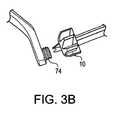
- FIGS. 3A and 3B illustrate a C-ring and a retrograde rotary drill cutter according to the present invention;
- FIG. 4 schematically illustrates an initial, stage in the formation of a tibial socket according to the present invention;
- FIG. 5 schematically illustrates the formation of a tibial socket at a stage subsequent to that shown in FIG.4;
- FIG. 6 schematically illustrates the formation of a tibial socket at a stage subsequent to that shown in FIG. 5;
- FIG. 7 schematically illustrates the formation of a tibial socket at a stage subsequent to that shown in FIG. 6;
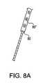
- FIG. 8A and 8B illustrate a drill depth grommet on a retrograde drill pin according to the present invention;
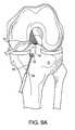
- FIG. 9A and 9B schematically illustrates the formation of a tibial socket at a stage subsequent to that shown in FIG. 7;
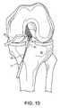
- FIG. 10 schematically illustrates the formation of a tibial tunnel at a stage subsequent to that shown in FIG. 9A;
- FIG. 11 schematically illustrates the formation of a tibial socket at a stage subsequent to that shown in FIG.10 or FIG. 9B;
- FIG. 12 schematically illustrates the formation of a tibial socket at a stage subsequent to that shown in FIG.11;
- FIG.13 schematically illustrates an initial stage in the formation of a femoral socket according to the present invention;
- FIG. 14 schematically illustrates the formation of a femoral socket at a stage subsequent to that shown in FIG. I3;
- FIG. 15 schematically illustrates the formation of a femoral socket at a stage subsequent to that shown in FIG. 14;
- FIG. 16 schematically illustrates the formation of a femoral socket at a stage subsequent to that shown in FIG 15;
- FIG. 17 schematically illustrates the formation of a femoral socket at a stage subsequent to that shown in FIG. 16;
- FIG. 18 schematically illustrates the formation of a femoral socket at a stage subsequent to that shown in FIG.17;
- FIG. 19 illustrates a schematic view of a knee joint undergoing graft insertion according to an embodiment of the present invention; and
- FIG. 20 illustrates a schematic view of a knee joint having undergone graft insertion and fixation according to an embodiment of the present invention.
- The present invention provides techniques for forming femoral and tibial bone sockets in a retrograde manner during ligament reconstruction, for example, anterior cruciate ligament (ACL) reconstruction. The present invention also provides methods of graft insertion and fixation employed in connection with the femoral and tibial sockets of the present invention.
- Referring now to the drawings, where like elements are designated by like reference numerals,FIGS. 1-2 illustrate a retrograde rotary drill cutter10 (FIGS. 1A-1C) which is adapted to be threadingly engaged with a cannulated retrograde drill pin50 (FIGS. 2A-2C).
- Referring toFIGS. 1A-1C, the retrograde
rotary drill cutter 10 features acylindrical body 11 having a plurality of cuttingteeth 12 radiating symmetrically. Acannulation 13 throughbody 11 is provided withinternal screw threads 14. Cuttingteeth 12 have edges extending radially fromcannulation 13 on aproximal cutting face 15, seen in plan view inFIG. 1A. The edges of cuttingteeth 12 continue axially along the side of the retrograderotary drill cutter 10, which is oriented orthogonally toproximal cutting face 15. The edges end at a smooth, roundeddistal end 16 of retrograderotary drill cutter 10. Retrograderotary drill cutter 10 is provided in a selected diameter corresponding to graft size as discussed further below. - Referring toFIGS. 2A-2B,
retrograde drill pin 50 features afluted region 51 formed ondistal end 52 of cannulatedbody 53, as shown in detail inFIG. 2B.Cannulated body 53 has aproximal end 54. The cannulatedbody 53 is provided withscrew threads 55 atdistal end 52. Thescrew threads 55 are fashioned to engage correspondingthreads 14 of retrograderotary drill cutter 10. Accordingly, the outer diameter of threadedregion 55 closely approximates the diameter ofcannula 13 of the retrograderotary drill cutter 10, to allow secure engagement of the outer threadedregion 55 with theinner threads 14 of retrograderotary drill cutter 10. Retrograde drill pin 50 features visible calibrateddepth markings 56 lased onto the cannulatedbody 53. Betweenthreads 55 anddepth markings 56, ashoulder 57 is formed to provide a stop wherethreads 55 end. The lumen of cannulatedbody 53 accepts atrocar 58 having a pointedtip 59. When the trocar is removed, a strand can be passed through the lumen of the cannulatedbody 53, as described below in greater detail. Theproximal end 54 of cannulatedbody 53 is configured for chucking into a rotary driver (not shown). Thedistal end 52 of cannulatedbody 53 is open at the tip to expose thepointed end 59 when thetrocar 58 is inserted into the cannulatedbody 53, as when drilling the assembledretrograde drill pin 50 into bone.Retrograde drill pin 50 includes asetscrew collar 62 for securing thetrocar 58 in the cannulatedbody 53.- Referring toFIGS. 3A-3B, drill guide C-
ring 70 features visible calibratedangular markings 70" circumferentially lased onto the body (not shown). A groove (not shown) near one end of the drill guide C-ring 70 is provided to secure a retrogradedrill guide sleeve 71. A holdingmember 72" movable along the circumference of the drill guide C-ring 70 is provided to secure atibial guide 72 or afemoral guide 83. The holdingmember 72" facilitates angular adjustment of thetibial guide 72 or thefemoral guide 83 relative to the retrogradedrill guide sleeve 71. Thetibial guide 72 or thefemoral guide 83 is provided with aninsertion post 74 to allow secure engagement of the retrograderotary drill cutter 10. - A method of using the drill guide C-
ring 70, theretrograde drill pin 50, thetibial guide 72, and the retrograderotary drill cutter 10 to create atibial socket 81 of the present invention is described below with reference toFIGS. 4-12, which illustrate a schematic anterior view of a knee in which ACL reconstruction is performed according to the present invention. In the following embodiment of the present invention, a tibial socket81 (shown completed inFIGS. 10-12) is formed in atibia 75. - Referring toFIGS. 4-5, the appropriate diameter retrograde
rotary drill cutter 10 is threaded onto theinsertion post 74 of thetibial guide 72. Thetibial guide 72 is inserted through the anteromedial portal (not shown) and the retrograderotary drill cutter 10 is placed on the anatomical origin of the ACL tibial insertion. Theretrograde drill pin 50 is adjusted to an appropriate angle, to avoid existing tunnels and fixation hardware, for insertion onto thetibia 75. - Once the anatomical position in the joint for the tibial socket has been identified, and the appropriate drilling angle has been selected on the drill guide C-
ring 70, the retrogradedrill guide sleeve 71 is inserted into thetibia 75 through a small stab incision on thetibia 75. Theretrograde drill pin 50 is drilled through the tibia, in a forward direction, to createpin hole 78 of a given diameter, for example 3mm, as shown inFIG. 5. - The
retrograde drill pin 50 is drilled through thetibia 75 until contact is made with the retrograderotary drill cutter 10 under arthroscopic control, as shown inFIG. 6. Referring toFIG. 7, as threads of theretrograde drill pin 50 engage the retrograderotary drill cutter 10, the reverse threads on theinsertion post 74 of thetibial guide 72 facilitate simultaneous disengagement of the retrograderotary drill cutter 10 from theinsertion post 74 onto theretrograde drill pin 50. Once securely engaged within the retrograderotary drill cutter 10, theretrograde drill pin 50 is rotated with a power driver (not shown) and retracted (retrograde) to cut through the tibial joint surface. - As is illustrated inFIGS. 8A-8B, the
drill depth grommet 80 on theretrograde drill pin 50 is advanced to the end of the retrogradedrill guide sleeve 71 for socket depth assessment during drilling. As shown inFIG. 9A, theretrograde drill pin 50 is retracted to facilitate retrograde drilling of the tibial joint surface and into thetibia 75 to create atibial socket 81. A desired depth D1, preferably 25 mm., is obtained by reading themarkings 80" on theretrograde drill pin 50, recorded relative to the skin tibial surface prior to and during socket formation. Alternatively, atibial tunnel 81" may be created by continuing drilling through the distal cortex, as shown inFIG. 9B. - Once the desired socket depth D1 is achieved, the
retrograde drill pin 50 is advanced forward until the retrograderotary drill cutter 10 engages theinsertion post 74 on thetibial guide 72, as shown inFIG. 10. Reverse-drilling of theretrograde drill pin 50 securely engages the retrograderotary drill cutter 10 on theinsertion post 74 and simultaneously disengages the retrograderotary drill cutter 10 from the threadedretrograde drill pin 50. The retrogradedrill guide sleeve 71 is pulled back, theretrograde drill pin 50 is removed from the drill guide C-ring 70, and thetibial guide 72 is removed from the knee joint Theretrograde drill pin 50 is left in place in thepin hole 78 and the tibial socket. - Referring toFIG. 12, a
tibial strand 82, such as Arthrex #2 FiberStick, described in U.S. Patent Application Publ.No. 2003/0153948 , is passed through the cannulation of theretrograde drill pin 50 into the joint and theretrograde drill pin 50 is withdrawn The end of the tibial strand is retrieved from an anteromedial portal (not shown) and a loop is formed for subsequent use in the installation of a graft. - Creation of a
femoral socket 84 continues in a manner similar to that for creating thetibial socket 81 and is described below with reference toFiGS. 13-18, which illustrate a schematic anterior view of a knee in which ACL reconstruction is performed according to the present invention. In the following embodiment of the present invention, a femoral socket84 (shown completed inFIGS. 16-18) is formed in thefemur 76. - Referring toFIGS. 13 and 14, the appropnate;diameter retrograde
rotary drill cutter 10 is threaded onto theinsertion post 74 of thefemoral guide 83, Thefemoral guide 83 is inserted through the anteromedial portal (not shown) and the retrograderotary drill cutter 10 is placed on the anatomical origin of the ACL femoral origin. Theretrograde drill pin 50 is adjusted to an appropriate angle, to avoid existing tunnels and fixation hardware, for insertion onto thefemur 76. Once the anatomical position in the joint for the femoral socket has been identified, and the appropriate drilling angle has been selected on the drill guide C-ring 70, the retrogradedrill guide sleeve 71 is inserted into thefemur 76 through a small stab incision on the lateral thigh (not shown), Theretrograde drill pin 50 is drilled through thefemur 76, in a forward direction, to createpin hole 78" of a given diameter, for example 3mm, as shown inFIG. 15. - The
retrograde drill pin 50 is drilled through thefemur 76 until contact is made with the retrograderotary drill cutter 10 under arthroscopic control. Referring toFIG. 15, as threads of theretrograde drill pin 50 engage the retrograderotary drill cutter 10, the reverse threads on theinsertion post 74 of thefemoral guide 83 facilitate simultaneous disengagement of the retrograderotary drill cutter 10 from theinsertion post 74 onto theretrograde drill pin 50. Once securely engaged within the retrograderotary drill cutter 10, theretrograde drill pin 50 is rotated with a power driver (not shown) and retracted (retrograde) to cut through the femoral joint surface and into thefemur 76 to create afemoral socket 84, as shown inFIGS. 15-16. - A desired depth D2, preferably 25 mm, is obtained by reading the
markings 80" on theretrograde drill pin 50, recorded relative to the skin femoral surface prior to and during socket formation. Once the desired socket depth D2 is achieved, theretrograde drill pin 50 is advanced forward until the retrograderotary drill cutter 10 engages theinsertion post 74 on thefemoral guide 83, as shown inFIG. 17. Reverse-drilling of theretrograde drill pin 50 securely engages the retrograderotary drill cutter 10 on theinsertion post 74 and simultaneously disengages the retrograderotary drill cutter 10 from the threadedretrograde drill pin 50. The retrogradedrill guide sleeve 71 is pulled back theretrograde drill pin 50 is removed from the drill guide C-ring 70, and thefemoral guide 83 is removed from the knee joint. Theretrograde drill pin 50 is left in place in thepin hole 78" and thefemoral socket 84, - Referring toFIG. 18, a
femoral strand 85, such as Arthrex #2 FiberStick, described in U.S. Patent Application Publ.No. 2003/0153948 , is passed through the cannulation of theretrograde drill pin 50 into the joint and theretrograde drill pin 50 is withdrawn, The end of thefemoral strand 85 is retrieved from an anteromedial portal (not shown) and aloop 91 is formed for subsequent use in the installation of a graft - A soft tissue graft or a composite femoral bone/tendon allograft is prepared for insertion and fixation into the
femoral socket 84 andtibial socket 81. The graft is selected so that its diameter corresponds to the diameters of the femoral andtibial sockets rotary drill cutter 10 may be selected to correspond to the diameter of a previously-prepared graft. Thegraft 86 has a given length equal to about 10mm shorter than the summed lengths of the femoral and tibial sockets and the intraarticular space. For example, assuming that the length D1 of thetibial socket 81 is about 25 millimeters, the length D2 of thefemoral socket 84 is about 25 millimeters, and the intraarticular length D between the two sockets is about 30 millimeters, the total length L of thegraft 86 is about (25+25+30-10) millimeters, or about 70 millimeters. Installation of thegraft 86 is illustrated schematically inFIGS. 19-20. Thegraft 86 is pulled through the anteromedial portal (not shown) by theloops tibial strand 82 and thefemoral strand 85. The ends of thegraft 86 are drawn into the femoral84 andtibial 81 sockets, as shown inFIGS.19-20. Thegraft suture 93 is tied over the lateral femoral cortex. The knee is brought into near extension, thegraft 86 appropriately tensioned and thegraft suture 92 is tied over the tibial cortex. A graft tension measuring device, such as Arthrex Tensioning Device AR-4002, may be used to quantify the tension in thegraft 86 during tibial fixation. Thesutures button 87, such as the Arthrex titanium Suture Button, Part No. AR-8920. - While the present invention is described herein with reference to illustrative embodiments for particular applications, it should be understood that the invention is not limited thereto. Those having ordinary skill in the art and access to the teachings provided herein will recognize additional modifications, applications, embodiments and substitution of equivalents all fall within the scope of the invention. Accordingly, the invention is not to be considered as limited by the foregoing description, but instead is limited by the scope of the appended claims.
Claims (6)
- A system for retrograde drilling of openings in bone, comprising:a rotary drill cutter comprising a cylindrically shaped body provided with a threaded cannulation and radially outward, cutting teeth for retrograde drilling of a socket in bone;a guide including a threaded post for threadably engaging and mountingthe rotary drill cutter; anda drill pin having a threaded distal end corresponding to the threaded cannulation of the rotary drill cutter, for threadably engaging the rotary drill cutter, wherein the rotary drill cutter is transferred from the guide tothe drill pin by advancing the drill pin into the cannulation of the rotary drill cutter and rotating the drill pin in a first direction to threadably engagethe drill pin with the rotary drill cutter mounted on the guide, andsimultaneously threadably disengage the rotary drill cutter from the guide.
- A system for retrograde drilling of openings in bone as recited in claim 1, further comprising a C-ring for mounting the guide and positioning the guide with respect to the bone, the C-ring further including a sleeve for guiding the drill pin such that the drill pin is directed into engagement with the cannulation of the rotary drill cutter mounted on the guide, as the drill pin is advanced through the sleeve.
- A system for retrograde drilling of openings in bone as recited in claim 2, wherein the position of the guide is adjustable on the C-ring to facilitate angular adjustment of the guide relative to the drill pin
- A system for retrograde drilling of openings in bone as recited in claim 3, wherein the C-ring is provided with calibrated angular scale markings.
- A system for retrograde drilling of openings in bone as recited in claim 4, wherein the drill pin comprises a cannulated shaft having a proximal end and a distal end, a fluted region formed on the distal end of the cannulated shaft for drilling through bone; and a threaded portion located near the distal end of the cannulated shaft and corresponding to inner threads of the cannulation of a rotary drill cutter.
- A system for retrograde drilling of openings in bone as recited in claim 5, wherein the drill pin is provided with a depth-measuring grommet located axially on the retrograde drill pin for depth assessment during drilling.
Applications Claiming Priority (2)
| Application Number | Priority Date | Filing Date | Title |
|---|---|---|---|
| US73519705P | 2005-11-10 | 2005-11-10 | |
| US79451206P | 2006-04-25 | 2006-04-25 |
Publications (2)
| Publication Number | Publication Date |
|---|---|
| EP1785103A1true EP1785103A1 (en) | 2007-05-16 |
| EP1785103B1 EP1785103B1 (en) | 2010-09-15 |
Family
ID=37834188
Family Applications (1)
| Application Number | Title | Priority Date | Filing Date |
|---|---|---|---|
| EP06023424AActiveEP1785103B1 (en) | 2005-11-10 | 2006-11-10 | Apparatus for anterior cruciate ligament (ACL) reconstruction using rotary drill cutter to form retrograde sockets |
Country Status (4)
| Country | Link |
|---|---|
| US (2) | US8668738B2 (en) |
| EP (1) | EP1785103B1 (en) |
| AT (1) | ATE481039T1 (en) |
| DE (1) | DE602006016904D1 (en) |
Cited By (24)
| Publication number | Priority date | Publication date | Assignee | Title |
|---|---|---|---|---|
| EP1987786A3 (en)* | 2007-05-02 | 2008-12-10 | Arthrex, Inc. | Flip retrograde cutting instrument |
| WO2009111694A1 (en)* | 2008-03-06 | 2009-09-11 | Smith & Nephew, Inc | Retrodrill system |
| EP2433575A1 (en) | 2010-09-23 | 2012-03-28 | Richard Wolf GmbH | Medical drill |
| WO2013192080A1 (en)* | 2012-06-18 | 2013-12-27 | Smith & Nephew, Inc. | Modular reamer retrograde attachment |
| US8652139B2 (en) | 2007-05-02 | 2014-02-18 | Arthrex, Inc. | Flip retrograde cutting instrument |
| CN104055578A (en)* | 2014-06-26 | 2014-09-24 | 复旦大学附属华山医院 | Posterior cruciate ligament tibial insertion stripping-positioning line threading device |
| US8888781B2 (en) | 2007-05-02 | 2014-11-18 | Arthrex, Inc. | Combined flip cutter and drill |
| US9668750B2 (en) | 2013-04-24 | 2017-06-06 | T.A.G. Medical Devices—Agriculture Cooperative Ltd. | Bone material removal devices |
| WO2017139187A1 (en)* | 2016-02-08 | 2017-08-17 | Arthrex, Inc | Cartilage trimmers and associated methods |
| WO2018051356A1 (en)* | 2016-09-18 | 2018-03-22 | T.A.G. Medical Devices - Agriculture Cooperative Ltd. | Multiple head drill |
| US9924951B2 (en) | 2011-03-11 | 2018-03-27 | Smith & Nephew, Inc. | Cutting instrument |
| EP3335646A1 (en)* | 2011-06-27 | 2018-06-20 | Biomet Sports Medicine, LLC | System for repairing bone defects |
| US10028800B2 (en) | 2014-05-29 | 2018-07-24 | Smith & Nephew, Inc. | Retrograde reamer depth tube gage |
| US10105150B2 (en) | 2013-03-12 | 2018-10-23 | Smith & Newphew, Inc. | Retro guidewire reamer |
| US10357259B2 (en) | 2012-12-05 | 2019-07-23 | Smith & Nephew, Inc. | Surgical instrument |
| US10398416B2 (en) | 2014-10-01 | 2019-09-03 | Smith & Nephew, Inc. | Bone marrow lesion drill |
| US10448959B2 (en) | 2015-04-09 | 2019-10-22 | T.A.G. Medical Devices—Agriculture Cooperative Ltd. | Bone material removal device and a method for use thereof |
| US10537340B2 (en) | 2014-10-19 | 2020-01-21 | T.A.G. Medical Devices—Agriculture Cooperative Ltd. | Kit including a guiding system and a bone material removal device |
| US10660657B2 (en) | 2016-02-11 | 2020-05-26 | T.A.G. Medical Devices—Agriculture Cooperative Ltd. | Bone material removal device and a method for use thereof |
| CN112022349A (en)* | 2020-09-25 | 2020-12-04 | 上海交通大学 | Three-dimensional accurate location anterior fork ligament dissects director of rebuilding tunnel |
| US11020132B2 (en) | 2016-04-24 | 2021-06-01 | T.A.G. Medical Devices—Agriculture Cooperative Ltd. | Guiding device and method of using thereof |
| US11202641B2 (en) | 2018-08-01 | 2021-12-21 | T.A.G. Medical Devices—Agriculture Cooperative Ltd. | Adjustable drilling device and a method for use thereof |
| EP2433571B1 (en)* | 2010-09-23 | 2022-09-28 | Tornier, Inc. | System for bone anchor inserter depth indication |
| CN116269627A (en)* | 2023-05-24 | 2023-06-23 | 杭州锐健马斯汀医疗器材有限公司 | Positioning device |
Families Citing this family (84)
| Publication number | Priority date | Publication date | Assignee | Title |
|---|---|---|---|---|
| US7713305B2 (en)* | 2000-05-01 | 2010-05-11 | Arthrosurface, Inc. | Articular surface implant |
| US7618462B2 (en) | 2000-05-01 | 2009-11-17 | Arthrosurface Incorporated | System and method for joint resurface repair |
| US6610067B2 (en) | 2000-05-01 | 2003-08-26 | Arthrosurface, Incorporated | System and method for joint resurface repair |
| US7163541B2 (en) | 2002-12-03 | 2007-01-16 | Arthrosurface Incorporated | Tibial resurfacing system |
| US6520964B2 (en)* | 2000-05-01 | 2003-02-18 | Std Manufacturing, Inc. | System and method for joint resurface repair |
| US7678151B2 (en)* | 2000-05-01 | 2010-03-16 | Ek Steven W | System and method for joint resurface repair |
| US8177841B2 (en) | 2000-05-01 | 2012-05-15 | Arthrosurface Inc. | System and method for joint resurface repair |
| US7914545B2 (en) | 2002-12-03 | 2011-03-29 | Arthrosurface, Inc | System and method for retrograde procedure |
| US7901408B2 (en) | 2002-12-03 | 2011-03-08 | Arthrosurface, Inc. | System and method for retrograde procedure |
| US8388624B2 (en) | 2003-02-24 | 2013-03-05 | Arthrosurface Incorporated | Trochlear resurfacing system and method |
| AU2004293042A1 (en) | 2003-11-20 | 2005-06-09 | Arthrosurface, Inc. | Retrograde delivery of resurfacing devices |
| US7951163B2 (en)* | 2003-11-20 | 2011-05-31 | Arthrosurface, Inc. | Retrograde excision system and apparatus |
| WO2006004885A2 (en) | 2004-06-28 | 2006-01-12 | Arthrosurface, Inc. | System for articular surface replacement |
| US7828853B2 (en) | 2004-11-22 | 2010-11-09 | Arthrosurface, Inc. | Articular surface implant and delivery system |
| WO2007016540A2 (en)* | 2005-07-29 | 2007-02-08 | Arthrosurface, Inc. | System and method for articular surface repair |
| US8038678B2 (en)* | 2006-04-25 | 2011-10-18 | Arthrex, Inc. | Arthroscopic unicompartmental knee and method of formation |
| US9358029B2 (en) | 2006-12-11 | 2016-06-07 | Arthrosurface Incorporated | Retrograde resection apparatus and method |
| US8083803B2 (en)* | 2007-05-03 | 2011-12-27 | Arthrex, Inc. | Arthroscopic unicompartmental knee technique and instrumentation |
| US8956278B2 (en) | 2007-12-21 | 2015-02-17 | Smith & Nephew, Inc. | Multiple portal guide |
| US9826992B2 (en) | 2007-12-21 | 2017-11-28 | Smith & Nephew, Inc. | Multiple portal guide |
| US8282647B2 (en)* | 2008-02-21 | 2012-10-09 | Tyco Healthcare Group Lp | Femoral guide for ACL repair having adjustable offset |
| US8430884B2 (en) | 2008-02-21 | 2013-04-30 | Covidien Lp | Femoral guide for ACL repair having selectively deployable femoral surface engagement member |
| US8343161B2 (en)* | 2008-02-21 | 2013-01-01 | Covidien Lp | Femoral guide for ACL repair having multiple lumen |
| US8298239B2 (en)* | 2008-02-21 | 2012-10-30 | Tyco Healthcare Group Lp | Tibial guide for ACL repair having interchangeable and/or rotatable outrigger |
| US8430883B2 (en)* | 2008-02-21 | 2013-04-30 | Covidien Lp | Femoral guide for ACL repair having reduced profile for left/right knee configurations |
| US20100049198A1 (en)* | 2008-02-21 | 2010-02-25 | Tyco Healthcare Group Lp | Tibial guide for acl repair having off-axis guide wire arrangement |
| US8292894B2 (en) | 2008-02-21 | 2012-10-23 | Tyco Healthcare Group Lp | Device for orienting the tibial tunnel position during an ACL reconstruction |
| US20100049199A1 (en)* | 2008-02-21 | 2010-02-25 | Tyco Healthcare Group Lp | Tibial guide for acl repair having moveable distal features |
| US8323289B2 (en)* | 2008-02-21 | 2012-12-04 | Covidien Lp | Tibial guide for ACL repair having left/right docking configuration |
| US20090216243A1 (en)* | 2008-02-21 | 2009-08-27 | Paul Re | Guide for creating femoral tunnel during acl reconstruction |
| US8475534B2 (en)* | 2008-02-29 | 2013-07-02 | Arthrex, Inc. | Canine elbow repair and instrumentation |
| EP2262448A4 (en) | 2008-03-03 | 2014-03-26 | Arthrosurface Inc | Bone resurfacing system and method |
| AU2009222580B2 (en) | 2008-10-10 | 2014-11-27 | Depuy Mitek, Inc. | Method for replacing a ligament in a knee |
| US8277458B2 (en)* | 2009-01-23 | 2012-10-02 | Biomet Sports Medicine, Llc | Apparatus and method for arthroscopic transhumeral rotator cuff repair |
| JP2010251529A (en)* | 2009-04-16 | 2010-11-04 | Sony Corp | Semiconductor memory device and manufacturing method thereof |
| US10945743B2 (en) | 2009-04-17 | 2021-03-16 | Arthrosurface Incorporated | Glenoid repair system and methods of use thereof |
| WO2010121250A1 (en) | 2009-04-17 | 2010-10-21 | Arthrosurface Incorporated | Glenoid resurfacing system and method |
| AU2010236182A1 (en) | 2009-04-17 | 2011-11-24 | Arthrosurface Incorporated | Glenoid resurfacing system and method |
| US8738144B2 (en)* | 2009-05-12 | 2014-05-27 | Ingenium, Llc | Bioelectric implant and method |
| US8449552B2 (en)* | 2009-06-04 | 2013-05-28 | Quantum Surgical | Surgical drill guide with awl and method of use |
| US8535330B2 (en)* | 2009-07-02 | 2013-09-17 | Arthrex, Inc. | Arthroscopic tibial sizer |
| EP2269519A1 (en)* | 2009-07-02 | 2011-01-05 | Arthrex, Inc. | Tibial rasp |
| US9241720B2 (en)* | 2009-07-10 | 2016-01-26 | Peter Forsell | Hip joint instrument and method |
| EP2542165A4 (en) | 2010-03-05 | 2015-10-07 | Arthrosurface Inc | Tibial resurfacing system and method |
| AU2010203095B2 (en)* | 2010-07-20 | 2015-09-24 | Ingenium, Llc | Apparatus and method for arthroscopic transhumeral rotator cuff repair |
| MX2013003496A (en) | 2010-09-27 | 2013-12-02 | Smith & Nephew Inc | Device and methods for use during arthroscopic surgery. |
| WO2012061639A1 (en) | 2010-11-03 | 2012-05-10 | Smith & Nephew, Inc. | Drill guide |
| US9066716B2 (en) | 2011-03-30 | 2015-06-30 | Arthrosurface Incorporated | Suture coil and suture sheath for tissue repair |
| US8685033B2 (en)* | 2011-06-27 | 2014-04-01 | Smith & Nephew, Inc. | Anatomic femoral guide |
| US8870884B2 (en) | 2011-06-27 | 2014-10-28 | Biomet Sports Medicine, Llc | Method for repairing bone defects |
| US8951263B2 (en) | 2011-07-08 | 2015-02-10 | Smith & Nephew, Inc. | Orthopedic suture passer and method |
| US9357997B2 (en) | 2011-07-08 | 2016-06-07 | Smith & Nephew, Inc. | Suture passer and method |
| US8784427B2 (en) | 2011-07-08 | 2014-07-22 | Smith & Nephew, Inc. | Orthopedic guide and method |
| US8888849B2 (en) | 2011-07-08 | 2014-11-18 | Smith & Nephew, Inc. | Soft tissue repair |
| US8801727B2 (en) | 2011-07-08 | 2014-08-12 | Smith & Nephew, Inc. | Orthopedic suture passer and method |
| US9955963B2 (en) | 2011-07-08 | 2018-05-01 | Smith & Nephew, Inc. | Soft tissue repair |
| US9241784B2 (en) | 2011-07-08 | 2016-01-26 | Smith & Nephew, Inc. | Soft tissue reconstruction |
| AU2012282919B2 (en)* | 2011-07-08 | 2017-04-13 | Smith & Nephew, Inc. | Orthopedic instruments |
| US9907558B2 (en) | 2011-07-08 | 2018-03-06 | Smith & Nephew, Inc. | Osteotomy guide and method |
| US9662105B2 (en) | 2011-07-08 | 2017-05-30 | Smith & Nephew, Inc. | Suture passer and method |
| US8882834B2 (en) | 2011-07-08 | 2014-11-11 | Smith & Nephew, Inc. | Soft tissue repair |
| US9198676B2 (en) | 2011-07-26 | 2015-12-01 | Howmedica Osteonics Corp. | PCL guides for drilling tibial and femoral tunnels |
| US8617176B2 (en) | 2011-08-24 | 2013-12-31 | Depuy Mitek, Llc | Cross pinning guide devices and methods |
| EP2804565B1 (en) | 2011-12-22 | 2018-03-07 | Arthrosurface Incorporated | System for bone fixation |
| WO2014008126A1 (en) | 2012-07-03 | 2014-01-09 | Arthrosurface Incorporated | System and method for joint resurfacing and repair |
| KR101482558B1 (en) | 2012-11-12 | 2015-01-16 | 주식회사 솔고 바이오메디칼 | Device set for sugical operation of posterior cruciated ligament |
| US9265600B2 (en) | 2013-02-27 | 2016-02-23 | Orthopediatrics Corp. | Graft fixation |
| US9492200B2 (en) | 2013-04-16 | 2016-11-15 | Arthrosurface Incorporated | Suture system and method |
| US10624748B2 (en) | 2014-03-07 | 2020-04-21 | Arthrosurface Incorporated | System and method for repairing articular surfaces |
| US11607319B2 (en) | 2014-03-07 | 2023-03-21 | Arthrosurface Incorporated | System and method for repairing articular surfaces |
| US9931219B2 (en) | 2014-03-07 | 2018-04-03 | Arthrosurface Incorporated | Implant and anchor assembly |
| WO2015153442A1 (en)* | 2014-03-31 | 2015-10-08 | The Curators Of The University Of Missouri | System, apparatus, and method for creation and implantation of tissue grafts |
| US9925068B2 (en) | 2014-05-30 | 2018-03-27 | Treace Medical Concepts, Inc. | Bone harvester and bone marrow removal system and method |
| WO2016149173A1 (en)* | 2015-03-14 | 2016-09-22 | University Of Cincinnati | Retrograde reamer system and methods for providing bone tunnels in ligament reconstruction surgery |
| AU2017368170B2 (en)* | 2016-12-01 | 2022-12-15 | Smith & Nephew, Inc. | Surgical drill guide system with articulating guide adaptor |
| US11160663B2 (en) | 2017-08-04 | 2021-11-02 | Arthrosurface Incorporated | Multicomponent articular surface implant |
| WO2020186099A1 (en) | 2019-03-12 | 2020-09-17 | Arthrosurface Incorporated | Humeral and glenoid articular surface implant systems and methods |
| US11357517B1 (en) | 2019-04-25 | 2022-06-14 | Nirav H. Amin | System and method for creating graft tunnels in bone |
| EP3975939B1 (en) | 2019-05-29 | 2024-11-13 | Wright Medical Technology, Inc. | Device for preparing a tibia for receiving tibial implant component of a replacement ankle |
| WO2021146015A1 (en) | 2020-01-17 | 2021-07-22 | Wright Medical Technology, Inc. | Guidance tools, systems, and methods |
| CN112370115A (en)* | 2020-11-16 | 2021-02-19 | 中国人民解放军海军军医大学第一附属医院 | Front fork positioner |
| CN112998804B (en)* | 2021-03-18 | 2022-02-01 | 中国人民解放军东部战区总医院 | Bone tunnel preparation device for knee joint ligament reconstruction |
| US20250017719A1 (en) | 2023-07-12 | 2025-01-16 | Integrity Medical Services Inc. | Tissue repair devices, systems, and methods |
| US12433583B1 (en) | 2024-05-31 | 2025-10-07 | Integrity Medical Services Inc. | Suture passer devices, systems, and methods |
Citations (3)
| Publication number | Priority date | Publication date | Assignee | Title |
|---|---|---|---|---|
| US5549613A (en)* | 1993-09-15 | 1996-08-27 | Mitek Surgical Products, Inc. | Modular surgical drill |
| US6015411A (en)* | 1996-10-23 | 2000-01-18 | Nagoya Screw Mfg. Co., Ltd. | Bone excavating apparatus for repairing ligament and a bone tunnel forming method |
| US20040199166A1 (en)* | 2003-03-18 | 2004-10-07 | Reinhold Schmieding | ACL reconstruction technique using retrodrill |
Family Cites Families (16)
| Publication number | Priority date | Publication date | Assignee | Title |
|---|---|---|---|---|
| CA1045752A (en) | 1975-05-26 | 1979-01-09 | Robert W. Jackson | Prosthetic implant |
| US5374270A (en) | 1991-12-13 | 1994-12-20 | David A. McGuire | Device and method for insertion of guide pin |
| US5211647A (en) | 1992-02-19 | 1993-05-18 | Arthrex Inc. | Interference screw and cannulated sheath for endosteal fixation of ligaments |
| US5919196A (en)* | 1995-02-16 | 1999-07-06 | Arthrex, Inc. | Method and apparatus for osteochondral autograft transplantation |
| US6083522A (en) | 1997-01-09 | 2000-07-04 | Neucoll, Inc. | Devices for tissue repair and methods for preparation and use thereof |
| US5918604A (en)* | 1997-02-12 | 1999-07-06 | Arthrex, Inc. | Method of loading tendons into the knee |
| US6120511A (en)* | 1997-11-18 | 2000-09-19 | Chan; Kwan-Ho | Drill guide assembly and method for producing a bone tunnel |
| US6066173A (en)* | 1998-01-28 | 2000-05-23 | Ethicon, Inc. | Method and apparatus for fixing a graft in a bone tunnel |
| US6149654A (en) | 1998-05-21 | 2000-11-21 | Johnson; Lanny L. | Intra-articular drill |
| US6517546B2 (en)* | 2001-03-13 | 2003-02-11 | Gregory R. Whittaker | Method and apparatus for fixing a graft in a bone tunnel |
| US6783533B2 (en)* | 2001-11-21 | 2004-08-31 | Sythes Ag Chur | Attachable/detachable reaming head for surgical reamer |
| US7588595B2 (en)* | 2002-10-29 | 2009-09-15 | Stryker Endoscopy | Graft fixation device and method |
| US7160305B2 (en)* | 2003-03-07 | 2007-01-09 | Arthrex, Inc. | Retrodrill technique for insertion of autograft, allograft or synthetic osteochondral implants |
| US7458975B2 (en)* | 2004-12-21 | 2008-12-02 | Johnson & Johnson | Method of replacing an anterior cruciate ligament in the knee |
| US7833244B2 (en)* | 2005-04-20 | 2010-11-16 | Arthroscopic Innovations Llc | Suture fixation device and method for surgical repair |
| US7842042B2 (en)* | 2005-05-16 | 2010-11-30 | Arthrocare Corporation | Convergent tunnel guide apparatus and method |
- 2006
- 2006-11-10ATAT06023424Tpatent/ATE481039T1/enactive
- 2006-11-10EPEP06023424Apatent/EP1785103B1/enactiveActive
- 2006-11-10DEDE602006016904Tpatent/DE602006016904D1/enactiveActive
- 2006-11-13USUS11/598,093patent/US8668738B2/enactiveActive
- 2014
- 2014-03-10USUS14/203,171patent/US8939980B2/enactiveActive
Patent Citations (3)
| Publication number | Priority date | Publication date | Assignee | Title |
|---|---|---|---|---|
| US5549613A (en)* | 1993-09-15 | 1996-08-27 | Mitek Surgical Products, Inc. | Modular surgical drill |
| US6015411A (en)* | 1996-10-23 | 2000-01-18 | Nagoya Screw Mfg. Co., Ltd. | Bone excavating apparatus for repairing ligament and a bone tunnel forming method |
| US20040199166A1 (en)* | 2003-03-18 | 2004-10-07 | Reinhold Schmieding | ACL reconstruction technique using retrodrill |
Cited By (42)
| Publication number | Priority date | Publication date | Assignee | Title |
|---|---|---|---|---|
| US8888781B2 (en) | 2007-05-02 | 2014-11-18 | Arthrex, Inc. | Combined flip cutter and drill |
| EP1987786A3 (en)* | 2007-05-02 | 2008-12-10 | Arthrex, Inc. | Flip retrograde cutting instrument |
| US9526510B2 (en) | 2007-05-02 | 2016-12-27 | Arthrex, Inc. | Combined flip cutter and drill |
| US9101366B2 (en) | 2007-05-02 | 2015-08-11 | Arthrex, Inc. | Flip retrograde cutting instrument |
| US8652139B2 (en) | 2007-05-02 | 2014-02-18 | Arthrex, Inc. | Flip retrograde cutting instrument |
| WO2009111694A1 (en)* | 2008-03-06 | 2009-09-11 | Smith & Nephew, Inc | Retrodrill system |
| EP2433571B1 (en)* | 2010-09-23 | 2022-09-28 | Tornier, Inc. | System for bone anchor inserter depth indication |
| DE102010046419A1 (en) | 2010-09-23 | 2012-03-29 | Richard Wolf Gmbh | Medical drill |
| EP2433575A1 (en) | 2010-09-23 | 2012-03-28 | Richard Wolf GmbH | Medical drill |
| US9924951B2 (en) | 2011-03-11 | 2018-03-27 | Smith & Nephew, Inc. | Cutting instrument |
| EP3335646A1 (en)* | 2011-06-27 | 2018-06-20 | Biomet Sports Medicine, LLC | System for repairing bone defects |
| AU2013277412B2 (en)* | 2012-06-18 | 2018-04-12 | Smith & Nephew, Inc. | Modular reamer retrograde attachment |
| WO2013192080A1 (en)* | 2012-06-18 | 2013-12-27 | Smith & Nephew, Inc. | Modular reamer retrograde attachment |
| US10357259B2 (en) | 2012-12-05 | 2019-07-23 | Smith & Nephew, Inc. | Surgical instrument |
| US10105150B2 (en) | 2013-03-12 | 2018-10-23 | Smith & Newphew, Inc. | Retro guidewire reamer |
| US10188403B2 (en) | 2013-04-24 | 2019-01-29 | T.A.G. Medical Devices—Agriculture Cooperative Ltd. | Bone material removal devices |
| US9668750B2 (en) | 2013-04-24 | 2017-06-06 | T.A.G. Medical Devices—Agriculture Cooperative Ltd. | Bone material removal devices |
| US10028800B2 (en) | 2014-05-29 | 2018-07-24 | Smith & Nephew, Inc. | Retrograde reamer depth tube gage |
| CN104055578B (en)* | 2014-06-26 | 2016-06-22 | 复旦大学附属华山医院 | Tibial insertion of posterior cruciate ligament peels off location wire-threading device |
| CN104055578A (en)* | 2014-06-26 | 2014-09-24 | 复旦大学附属华山医院 | Posterior cruciate ligament tibial insertion stripping-positioning line threading device |
| US10398416B2 (en) | 2014-10-01 | 2019-09-03 | Smith & Nephew, Inc. | Bone marrow lesion drill |
| US11033283B2 (en) | 2014-10-19 | 2021-06-15 | T.A.G. Medical Devices—Agriculture Cooperative Ltd. | Kit including a guiding system and a bone material removal device |
| US12310601B2 (en) | 2014-10-19 | 2025-05-27 | T.A.G. Medical Products Corporation Ltd. | Kit including a guiding system and a bone material removal device |
| US10537340B2 (en) | 2014-10-19 | 2020-01-21 | T.A.G. Medical Devices—Agriculture Cooperative Ltd. | Kit including a guiding system and a bone material removal device |
| US11896242B2 (en) | 2014-10-19 | 2024-02-13 | T.A.G. Medical Products Corporation Ltd. | Kit including a guiding system and a bone material removal device |
| US11779353B2 (en) | 2015-04-09 | 2023-10-10 | T.A.G. Medical Products Corporation Ltd. | Bone material removal device and a method for use thereof |
| US10448959B2 (en) | 2015-04-09 | 2019-10-22 | T.A.G. Medical Devices—Agriculture Cooperative Ltd. | Bone material removal device and a method for use thereof |
| US10485574B2 (en) | 2016-02-08 | 2019-11-26 | Arthrex, Inc. | Cartilage trimmers and associated methods |
| US9936971B2 (en) | 2016-02-08 | 2018-04-10 | Arthrex, Inc. | Cartilage trimmers and associated methods |
| WO2017139187A1 (en)* | 2016-02-08 | 2017-08-17 | Arthrex, Inc | Cartilage trimmers and associated methods |
| US12102337B2 (en) | 2016-02-11 | 2024-10-01 | T.A.G. Medical Products Corporation Ltd. | Bone material removal device and a method for use thereof |
| US10660657B2 (en) | 2016-02-11 | 2020-05-26 | T.A.G. Medical Devices—Agriculture Cooperative Ltd. | Bone material removal device and a method for use thereof |
| US11446042B2 (en) | 2016-02-11 | 2022-09-20 | T.A.G. Medical Products Corporation Ltd. | Bone material removal device and a method for use thereof |
| US11020132B2 (en) | 2016-04-24 | 2021-06-01 | T.A.G. Medical Devices—Agriculture Cooperative Ltd. | Guiding device and method of using thereof |
| US11350949B2 (en) | 2016-09-18 | 2022-06-07 | T.A.G. Medical Products Corporation Ltd. | Multiple head drill |
| WO2018051356A1 (en)* | 2016-09-18 | 2018-03-22 | T.A.G. Medical Devices - Agriculture Cooperative Ltd. | Multiple head drill |
| US11690635B2 (en) | 2018-08-01 | 2023-07-04 | T.A.G. Medical Products Corporation Ltd. | Adjustable drilling device and a method for use thereof |
| US11202641B2 (en) | 2018-08-01 | 2021-12-21 | T.A.G. Medical Devices—Agriculture Cooperative Ltd. | Adjustable drilling device and a method for use thereof |
| US12369927B2 (en) | 2018-08-01 | 2025-07-29 | T.A.G. Medical Products Corporation Ltd. | Adjustable drilling device and a method for use thereof |
| CN112022349A (en)* | 2020-09-25 | 2020-12-04 | 上海交通大学 | Three-dimensional accurate location anterior fork ligament dissects director of rebuilding tunnel |
| CN116269627A (en)* | 2023-05-24 | 2023-06-23 | 杭州锐健马斯汀医疗器材有限公司 | Positioning device |
| CN116269627B (en)* | 2023-05-24 | 2023-08-11 | 杭州锐健马斯汀医疗器材有限公司 | Positioning device |
Also Published As
| Publication number | Publication date |
|---|---|
| ATE481039T1 (en) | 2010-10-15 |
| EP1785103B1 (en) | 2010-09-15 |
| US20070233128A1 (en) | 2007-10-04 |
| US8668738B2 (en) | 2014-03-11 |
| US20140194880A1 (en) | 2014-07-10 |
| DE602006016904D1 (en) | 2010-10-28 |
| US8939980B2 (en) | 2015-01-27 |
Similar Documents
| Publication | Publication Date | Title |
|---|---|---|
| EP1785103B1 (en) | Apparatus for anterior cruciate ligament (ACL) reconstruction using rotary drill cutter to form retrograde sockets | |
| EP2120788B1 (en) | Drill pin for fixation of ligaments using button/loop construct | |
| EP1836977B1 (en) | Dual-sided rotary drill cutter for ACL reconstruction | |
| US5257996A (en) | Surgical pin passer | |
| US7238189B2 (en) | ACL reconstruction technique using retrodrill | |
| US7862567B2 (en) | Retrodrill technique for insertion of autograft, allograft or synthetic osteochondral implants | |
| JP3653616B2 (en) | Replacement ligament grafting and method | |
| US5374269A (en) | Method and instruments for ACL reconstruction | |
| US8784423B2 (en) | Tibial cross-pin fixation techniques and instrumentation | |
| US5865834A (en) | Coring reamer | |
| US8128634B2 (en) | Method and apparatus for fixing a graft in a bone tunnel | |
| US5320115A (en) | Method and apparatus for arthroscopic knee surgery | |
| US5234435A (en) | Surgical method and apparatus | |
| US9314332B2 (en) | Method and apparatus for fixing a graft in a bone tunnel | |
| US9814508B2 (en) | Methods and devices for ligament repair | |
| US5785714A (en) | Method of ACL reconstruction using double socket graft placement and fixation | |
| US20070233151A1 (en) | Universal anterior cruciate ligament repair and reconstruction system | |
| US9095332B2 (en) | Method and apparatus for attaching an elongated object to bone | |
| US20040254585A1 (en) | Method and apparatus for fixing a graft in a bone tunnel | |
| EP0739185B1 (en) | Allogenic or synthetic composite bone graft | |
| JP7342012B2 (en) | Fixation of the bone graft to the glenoid bone and its implementation | |
| EP3766439A1 (en) | Coracoid drill guide assembly |
Legal Events
| Date | Code | Title | Description |
|---|---|---|---|
| PUAI | Public reference made under article 153(3) epc to a published international application that has entered the european phase | Free format text:ORIGINAL CODE: 0009012 | |
| AK | Designated contracting states | Kind code of ref document:A1 Designated state(s):AT BE BG CH CY CZ DE DK EE ES FI FR GB GR HU IE IS IT LI LT LU LV MC NL PL PT RO SE SI SK TR | |
| AX | Request for extension of the european patent | Extension state:AL BA HR MK YU | |
| 17P | Request for examination filed | Effective date:20071022 | |
| 17Q | First examination report despatched | Effective date:20071221 | |
| AKX | Designation fees paid | Designated state(s):AT BE BG CH CY CZ DE DK EE ES FI FR GB GR HU IE IS IT LI LT LU LV MC NL PL PT RO SE SI SK TR | |
| GRAP | Despatch of communication of intention to grant a patent | Free format text:ORIGINAL CODE: EPIDOSNIGR1 | |
| GRAS | Grant fee paid | Free format text:ORIGINAL CODE: EPIDOSNIGR3 | |
| GRAA | (expected) grant | Free format text:ORIGINAL CODE: 0009210 | |
| AK | Designated contracting states | Kind code of ref document:B1 Designated state(s):AT BE BG CH CY CZ DE DK EE ES FI FR GB GR HU IE IS IT LI LT LU LV MC NL PL PT RO SE SI SK TR | |
| REG | Reference to a national code | Ref country code:CH Ref legal event code:EP Ref country code:GB Ref legal event code:FG4D | |
| REG | Reference to a national code | Ref country code:IE Ref legal event code:FG4D | |
| REF | Corresponds to: | Ref document number:602006016904 Country of ref document:DE Date of ref document:20101028 Kind code of ref document:P | |
| REG | Reference to a national code | Ref country code:NL Ref legal event code:VDEP Effective date:20100915 | |
| PG25 | Lapsed in a contracting state [announced via postgrant information from national office to epo] | Ref country code:LT Free format text:LAPSE BECAUSE OF FAILURE TO SUBMIT A TRANSLATION OF THE DESCRIPTION OR TO PAY THE FEE WITHIN THE PRESCRIBED TIME-LIMIT Effective date:20100915 Ref country code:FI Free format text:LAPSE BECAUSE OF FAILURE TO SUBMIT A TRANSLATION OF THE DESCRIPTION OR TO PAY THE FEE WITHIN THE PRESCRIBED TIME-LIMIT Effective date:20100915 | |
| LTIE | Lt: invalidation of european patent or patent extension | Effective date:20100915 | |
| PG25 | Lapsed in a contracting state [announced via postgrant information from national office to epo] | Ref country code:SI Free format text:LAPSE BECAUSE OF FAILURE TO SUBMIT A TRANSLATION OF THE DESCRIPTION OR TO PAY THE FEE WITHIN THE PRESCRIBED TIME-LIMIT Effective date:20100915 Ref country code:PL Free format text:LAPSE BECAUSE OF FAILURE TO SUBMIT A TRANSLATION OF THE DESCRIPTION OR TO PAY THE FEE WITHIN THE PRESCRIBED TIME-LIMIT Effective date:20100915 Ref country code:CY Free format text:LAPSE BECAUSE OF FAILURE TO SUBMIT A TRANSLATION OF THE DESCRIPTION OR TO PAY THE FEE WITHIN THE PRESCRIBED TIME-LIMIT Effective date:20100915 | |
| PG25 | Lapsed in a contracting state [announced via postgrant information from national office to epo] | Ref country code:LV Free format text:LAPSE BECAUSE OF FAILURE TO SUBMIT A TRANSLATION OF THE DESCRIPTION OR TO PAY THE FEE WITHIN THE PRESCRIBED TIME-LIMIT Effective date:20100915 Ref country code:SE Free format text:LAPSE BECAUSE OF FAILURE TO SUBMIT A TRANSLATION OF THE DESCRIPTION OR TO PAY THE FEE WITHIN THE PRESCRIBED TIME-LIMIT Effective date:20100915 Ref country code:GR Free format text:LAPSE BECAUSE OF FAILURE TO SUBMIT A TRANSLATION OF THE DESCRIPTION OR TO PAY THE FEE WITHIN THE PRESCRIBED TIME-LIMIT Effective date:20101216 | |
| PG25 | Lapsed in a contracting state [announced via postgrant information from national office to epo] | Ref country code:IS Free format text:LAPSE BECAUSE OF FAILURE TO SUBMIT A TRANSLATION OF THE DESCRIPTION OR TO PAY THE FEE WITHIN THE PRESCRIBED TIME-LIMIT Effective date:20110115 Ref country code:CZ Free format text:LAPSE BECAUSE OF FAILURE TO SUBMIT A TRANSLATION OF THE DESCRIPTION OR TO PAY THE FEE WITHIN THE PRESCRIBED TIME-LIMIT Effective date:20100915 Ref country code:EE Free format text:LAPSE BECAUSE OF FAILURE TO SUBMIT A TRANSLATION OF THE DESCRIPTION OR TO PAY THE FEE WITHIN THE PRESCRIBED TIME-LIMIT Effective date:20100915 Ref country code:NL Free format text:LAPSE BECAUSE OF FAILURE TO SUBMIT A TRANSLATION OF THE DESCRIPTION OR TO PAY THE FEE WITHIN THE PRESCRIBED TIME-LIMIT Effective date:20100915 Ref country code:RO Free format text:LAPSE BECAUSE OF FAILURE TO SUBMIT A TRANSLATION OF THE DESCRIPTION OR TO PAY THE FEE WITHIN THE PRESCRIBED TIME-LIMIT Effective date:20100915 Ref country code:PT Free format text:LAPSE BECAUSE OF FAILURE TO SUBMIT A TRANSLATION OF THE DESCRIPTION OR TO PAY THE FEE WITHIN THE PRESCRIBED TIME-LIMIT Effective date:20110117 Ref country code:SK Free format text:LAPSE BECAUSE OF FAILURE TO SUBMIT A TRANSLATION OF THE DESCRIPTION OR TO PAY THE FEE WITHIN THE PRESCRIBED TIME-LIMIT Effective date:20100915 | |
| PG25 | Lapsed in a contracting state [announced via postgrant information from national office to epo] | Ref country code:BE Free format text:LAPSE BECAUSE OF FAILURE TO SUBMIT A TRANSLATION OF THE DESCRIPTION OR TO PAY THE FEE WITHIN THE PRESCRIBED TIME-LIMIT Effective date:20100915 Ref country code:MC Free format text:LAPSE BECAUSE OF NON-PAYMENT OF DUE FEES Effective date:20101130 Ref country code:ES Free format text:LAPSE BECAUSE OF FAILURE TO SUBMIT A TRANSLATION OF THE DESCRIPTION OR TO PAY THE FEE WITHIN THE PRESCRIBED TIME-LIMIT Effective date:20101226 | |
| REG | Reference to a national code | Ref country code:CH Ref legal event code:PL | |
| PLBE | No opposition filed within time limit | Free format text:ORIGINAL CODE: 0009261 | |
| STAA | Information on the status of an ep patent application or granted ep patent | Free format text:STATUS: NO OPPOSITION FILED WITHIN TIME LIMIT | |
| PG25 | Lapsed in a contracting state [announced via postgrant information from national office to epo] | Ref country code:CH Free format text:LAPSE BECAUSE OF NON-PAYMENT OF DUE FEES Effective date:20101130 Ref country code:LI Free format text:LAPSE BECAUSE OF NON-PAYMENT OF DUE FEES Effective date:20101130 | |
| 26N | No opposition filed | Effective date:20110616 | |
| PG25 | Lapsed in a contracting state [announced via postgrant information from national office to epo] | Ref country code:DK Free format text:LAPSE BECAUSE OF FAILURE TO SUBMIT A TRANSLATION OF THE DESCRIPTION OR TO PAY THE FEE WITHIN THE PRESCRIBED TIME-LIMIT Effective date:20100915 | |
| REG | Reference to a national code | Ref country code:DE Ref legal event code:R097 Ref document number:602006016904 Country of ref document:DE Effective date:20110616 | |
| PG25 | Lapsed in a contracting state [announced via postgrant information from national office to epo] | Ref country code:IE Free format text:LAPSE BECAUSE OF NON-PAYMENT OF DUE FEES Effective date:20101110 | |
| PG25 | Lapsed in a contracting state [announced via postgrant information from national office to epo] | Ref country code:BG Free format text:LAPSE BECAUSE OF FAILURE TO SUBMIT A TRANSLATION OF THE DESCRIPTION OR TO PAY THE FEE WITHIN THE PRESCRIBED TIME-LIMIT Effective date:20100915 Ref country code:LU Free format text:LAPSE BECAUSE OF NON-PAYMENT OF DUE FEES Effective date:20101110 Ref country code:HU Free format text:LAPSE BECAUSE OF FAILURE TO SUBMIT A TRANSLATION OF THE DESCRIPTION OR TO PAY THE FEE WITHIN THE PRESCRIBED TIME-LIMIT Effective date:20110316 | |
| PG25 | Lapsed in a contracting state [announced via postgrant information from national office to epo] | Ref country code:TR Free format text:LAPSE BECAUSE OF FAILURE TO SUBMIT A TRANSLATION OF THE DESCRIPTION OR TO PAY THE FEE WITHIN THE PRESCRIBED TIME-LIMIT Effective date:20100915 | |
| PG25 | Lapsed in a contracting state [announced via postgrant information from national office to epo] | Ref country code:BG Free format text:LAPSE BECAUSE OF FAILURE TO SUBMIT A TRANSLATION OF THE DESCRIPTION OR TO PAY THE FEE WITHIN THE PRESCRIBED TIME-LIMIT Effective date:20101215 | |
| REG | Reference to a national code | Ref country code:FR Ref legal event code:PLFP Year of fee payment:10 | |
| REG | Reference to a national code | Ref country code:FR Ref legal event code:PLFP Year of fee payment:11 | |
| REG | Reference to a national code | Ref country code:FR Ref legal event code:PLFP Year of fee payment:12 | |
| REG | Reference to a national code | Ref country code:FR Ref legal event code:PLFP Year of fee payment:13 | |
| PGFP | Annual fee paid to national office [announced via postgrant information from national office to epo] | Ref country code:AT Payment date:20191025 Year of fee payment:14 | |
| REG | Reference to a national code | Ref country code:AT Ref legal event code:MM01 Ref document number:481039 Country of ref document:AT Kind code of ref document:T Effective date:20201110 | |
| PG25 | Lapsed in a contracting state [announced via postgrant information from national office to epo] | Ref country code:AT Free format text:LAPSE BECAUSE OF NON-PAYMENT OF DUE FEES Effective date:20201110 | |
| PGFP | Annual fee paid to national office [announced via postgrant information from national office to epo] | Ref country code:GB Payment date:20240919 Year of fee payment:19 | |
| PGFP | Annual fee paid to national office [announced via postgrant information from national office to epo] | Ref country code:FR Payment date:20240909 Year of fee payment:19 | |
| PGFP | Annual fee paid to national office [announced via postgrant information from national office to epo] | Ref country code:DE Payment date:20240925 Year of fee payment:19 | |
| PGFP | Annual fee paid to national office [announced via postgrant information from national office to epo] | Ref country code:IT Payment date:20241010 Year of fee payment:19 |