EP1783904B1 - HF plasma supply system - Google Patents
HF plasma supply systemDownload PDFInfo
- Publication number
- EP1783904B1 EP1783904B1EP20050022558EP05022558AEP1783904B1EP 1783904 B1EP1783904 B1EP 1783904B1EP 20050022558EP20050022558EP 20050022558EP 05022558 AEP05022558 AEP 05022558AEP 1783904 B1EP1783904 B1EP 1783904B1
- Authority
- EP
- European Patent Office
- Prior art keywords
- power
- plasma
- coupled
- generators
- signals
- Prior art date
- Legal status (The legal status is an assumption and is not a legal conclusion. Google has not performed a legal analysis and makes no representation as to the accuracy of the status listed.)
- Expired - Lifetime
Links
Images


Classifications
- H—ELECTRICITY
- H02—GENERATION; CONVERSION OR DISTRIBUTION OF ELECTRIC POWER
- H02M—APPARATUS FOR CONVERSION BETWEEN AC AND AC, BETWEEN AC AND DC, OR BETWEEN DC AND DC, AND FOR USE WITH MAINS OR SIMILAR POWER SUPPLY SYSTEMS; CONVERSION OF DC OR AC INPUT POWER INTO SURGE OUTPUT POWER; CONTROL OR REGULATION THEREOF
- H02M7/00—Conversion of AC power input into DC power output; Conversion of DC power input into AC power output
- H02M7/42—Conversion of DC power input into AC power output without possibility of reversal
- H02M7/44—Conversion of DC power input into AC power output without possibility of reversal by static converters
- H02M7/48—Conversion of DC power input into AC power output without possibility of reversal by static converters using discharge tubes with control electrode or semiconductor devices with control electrode
- H02M7/53—Conversion of DC power input into AC power output without possibility of reversal by static converters using discharge tubes with control electrode or semiconductor devices with control electrode using devices of a triode or transistor type requiring continuous application of a control signal
- H02M7/537—Conversion of DC power input into AC power output without possibility of reversal by static converters using discharge tubes with control electrode or semiconductor devices with control electrode using devices of a triode or transistor type requiring continuous application of a control signal using semiconductor devices only, e.g. single switched pulse inverters
- H02M7/5387—Conversion of DC power input into AC power output without possibility of reversal by static converters using discharge tubes with control electrode or semiconductor devices with control electrode using devices of a triode or transistor type requiring continuous application of a control signal using semiconductor devices only, e.g. single switched pulse inverters in a bridge configuration
- H—ELECTRICITY
- H01—ELECTRIC ELEMENTS
- H01J—ELECTRIC DISCHARGE TUBES OR DISCHARGE LAMPS
- H01J37/00—Discharge tubes with provision for introducing objects or material to be exposed to the discharge, e.g. for the purpose of examination or processing thereof
- H01J37/32—Gas-filled discharge tubes
- H01J37/32009—Arrangements for generation of plasma specially adapted for examination or treatment of objects, e.g. plasma sources
- H01J37/32082—Radio frequency generated discharge
- H01J37/32137—Radio frequency generated discharge controlling of the discharge by modulation of energy
- H01J37/32155—Frequency modulation
- H01J37/32165—Plural frequencies
- H—ELECTRICITY
- H01—ELECTRIC ELEMENTS
- H01J—ELECTRIC DISCHARGE TUBES OR DISCHARGE LAMPS
- H01J37/00—Discharge tubes with provision for introducing objects or material to be exposed to the discharge, e.g. for the purpose of examination or processing thereof
- H01J37/32—Gas-filled discharge tubes
- H01J37/32009—Arrangements for generation of plasma specially adapted for examination or treatment of objects, e.g. plasma sources
- H01J37/32082—Radio frequency generated discharge
- H01J37/32174—Circuits specially adapted for controlling the RF discharge
- H—ELECTRICITY
- H02—GENERATION; CONVERSION OR DISTRIBUTION OF ELECTRIC POWER
- H02M—APPARATUS FOR CONVERSION BETWEEN AC AND AC, BETWEEN AC AND DC, OR BETWEEN DC AND DC, AND FOR USE WITH MAINS OR SIMILAR POWER SUPPLY SYSTEMS; CONVERSION OF DC OR AC INPUT POWER INTO SURGE OUTPUT POWER; CONTROL OR REGULATION THEREOF
- H02M7/00—Conversion of AC power input into DC power output; Conversion of DC power input into AC power output
- H02M7/42—Conversion of DC power input into AC power output without possibility of reversal
- H02M7/44—Conversion of DC power input into AC power output without possibility of reversal by static converters
- H02M7/48—Conversion of DC power input into AC power output without possibility of reversal by static converters using discharge tubes with control electrode or semiconductor devices with control electrode
- H02M7/53—Conversion of DC power input into AC power output without possibility of reversal by static converters using discharge tubes with control electrode or semiconductor devices with control electrode using devices of a triode or transistor type requiring continuous application of a control signal
- H02M7/537—Conversion of DC power input into AC power output without possibility of reversal by static converters using discharge tubes with control electrode or semiconductor devices with control electrode using devices of a triode or transistor type requiring continuous application of a control signal using semiconductor devices only, e.g. single switched pulse inverters
- H02M7/5387—Conversion of DC power input into AC power output without possibility of reversal by static converters using discharge tubes with control electrode or semiconductor devices with control electrode using devices of a triode or transistor type requiring continuous application of a control signal using semiconductor devices only, e.g. single switched pulse inverters in a bridge configuration
- H02M7/53871—Conversion of DC power input into AC power output without possibility of reversal by static converters using discharge tubes with control electrode or semiconductor devices with control electrode using devices of a triode or transistor type requiring continuous application of a control signal using semiconductor devices only, e.g. single switched pulse inverters in a bridge configuration with automatic control of output voltage or current
- H02M7/53878—Conversion of DC power input into AC power output without possibility of reversal by static converters using discharge tubes with control electrode or semiconductor devices with control electrode using devices of a triode or transistor type requiring continuous application of a control signal using semiconductor devices only, e.g. single switched pulse inverters in a bridge configuration with automatic control of output voltage or current by time shifting switching signals of one diagonal pair of the bridge with respect to the other diagonal pair
Definitions
- rated outputsare specified by the manufacturer, the sum of the nominal powers of the individual HF generators representing the rated power of the plasma supply device (see, for example, US Pat EP 0 731 559 A1 ).
- HF generators and thus RF plasma supply devicescan only be operated with great difficulty at a fraction of their nominal power. They are prone to uncontrolled vibrations and are difficult to control to an accurate output power. In most cases, manufacturers of RF generators also specify a lower power limit, below which the HF generator can not be operated reliably or with the required accuracy can. This can for example be 10% of the nominal power, but it can also be at lower values, for example at 1%. The sum of the lower power limits of the HF generators results in about the lower. Power limit of the plasma supply device.
- RF plasma power suppliesare required to be very accurately tuned over a wide power range. This power range should be able to be passed continuously.
- the object of the present inventionis therefore to provide a method and a device which can be remedied in this regard.
- a control and / or regulation of the level and / or the phase position of the RF power signalsis such that for plasma power in the area represents an unessential part of the coupled RF power compensation power between a predetermined lower power limit and a given nominal power and represents a significant part of the coupled RF power balancing power for plasma power below the predetermined lower power limit.
- a plasma loadmay comprise a vacuum plasma processing chamber, e.g. for coating, etching or processing substrates by means of a plasma, or a plasma process taking place therein, or a laser excitation in a gas laser.
- RF frequenciesare understood to be frequencies in the range between 1 and 30 MHz.
- Preferred frequencies for plasma loadsare 13MHz and 27MHz.
- a lower compensation poweris set than for plasma powers below the predetermined lower power limit.
- the lower power limitcan be specified, for example, depending on the rated power. For example, a power in the range of 0.1% to 20% of the rated power can be specified as the lower power limit.
- the lower power limitis set at about 10% of the rated power.
- the levels and / or phases of the RF power signalsare set by controlling the DC and / or DC power supply of the RF power generators and / or is regulated.
- the level of plasma powerin particular in a power range above the lower power limit, can be set particularly easily.
- the rated power of each RF generatoris 1.5kW, for example, they both operate at 13.56MHz.
- the phase position and the levels of the two HF generatorsare adjusted so that as far as possible the entire coupled RF power is delivered to the plasma load. These are at rated power then 3kW.
- the power controlis performed, for example, by controlling the DC or DC power supply of the RF generators. If the RF plasma supply device operates in the range of ⁇ 10% of its nominal power, ie less than 300 W plasma power, the control of the plasma power is then preferably no longer compulsorily controlled by the control of the levels of the RF power signals of the HF generators (for example by controlling the DC or DC power supply) DC power supply), but preferably predominantly by controlling the phase position of the two RF generators to each other.
- the RF power signalsare generated by controlling switching elements in the RF generators.
- HF generators operating in switching modeare particularly low-loss and are therefore preferred for greater power.
- HF generators that are in the Switching operationare known, for example, Class-D (full bridge or half bridge) or Class-E, F amplifier or mixed forms thereof. These types of RF generators have one or more switching elements and an output circuit. The switching elements are switched on and off with a switching signal of a switching frequency.
- the output circuithas two functions: First, filtering the RF power signal so that essentially only the switching frequency reaches the output. Second, it should enable the low-loss switching of the switching elements.
- the output power of the single RF generatorcan be controlled by the DC or DC supply, for example.
- the HF generators operating in switching modeusually operate with MOSFETs as switching elements at frequencies above 1 MHz. These MOSFETs have an output capacitance Coss that is non-linearly dependent on the voltage at the output of the MOSFET between the drain and source terminals.
- the value for the lower power limitis usually not fixed at 10% of the nominal power, but varies in the range of 0.1% to 20% of the rated power depending on the desired rated power and the desired lowest power to be set can.
- Decisive for operating in switching mode RF generatorsis the non-linearity of the output capacitance and the tolerance of the circuit, which also depends on the maximum voltage at the switching element, the frequency, the power, etc.
- the levels and / or phases of the RF power signalscan be adjusted by the switching elements are driven in a phase-shift method.
- an RF generatormay have two half-bridges, each consisting of two mutually switching elements. By controlling the switching elements, the phase angle of the half-bridges and thus the power at the output of the HF generator are set. Even with this principle of power control very small power can be adjusted only insufficiently accurate. The control and / or regulation of the power to be supplied to a compensating load is therefore also advantageous in the case of this type of generation of the HF power signals in order to be able to reliably operate the entire RF plasma supply device.
- the RF power signalsare coupled in a 90 ° hybrid, in particular in a 3dB coupler.
- a 90 ° hybridenables power control at low power levels.
- coupling the RF power (input) signalsmeans adding the RF power signals to an added RF power as a coupled RF power. The added RF power is then divided depending on the level and / or phase of the RF power signals on two RF power (output) signals.
- Greater plasma powermay be generated when generating more than two RF power signals, with two RF power signals each being coupled to a coupled RF power signal.
- the coupling or addition of the RF power signalsis preferably carried out in a coupling element, so that advantageously also a plurality of balancing loads are provided and a plurality of equalization powers are generated accordingly.
- two RF power signalsare preferably coupled in the coupling links.
- Several coupling elementscan be cascaded, so that at the end of the cascade, an RF power signal is generated, which represents the plasma power to be supplied to a plasma load.
- At least one variable describing an RF poweris measured. It is conceivable to measure the RF power signals or these descriptive quantities at the output of at least one HF generator. Alternatively or additionally, a variable describing the plasma power and / or the compensation power can be detected. As a quantity describing an RF power, either the power itself or a voltage and / or a current can be detected.
- a variable measured in an RF generatorcan be used to control the RF power delivered by that generator.
- the detected plasma poweris used to control the RF power of one or more RF generators.
- the measured variables describing an RF powerare preferably supplied to a control and / or regulating device.
- an impedance matchingis performed.
- the impedance matchingis preferably performed between the plasma load and the plasma supply device.
- the scope of the inventionalso includes an RF plasma supply device for supplying a plasma load with plasma power, comprising at least two HF generators for generating a first and second RF power signal, and at least one coupling element, in which a paired RF signal is generated from two RF power signals. Power is generated, wherein the at least one coupling element, the plasma load and a balancing load are connected or connected, and with a control and / or regulating device which controls the RF generators and / or regulated, the control and / or regulating device for Implementation of the previously described method and / or its variants of the method is set up. With such a device, the advantages described above can be achieved.
- the methodis implemented in hardware, firmware and / or software.
- the advantage of an implementation in hardwareis that a fast, stepless power control can take place.
- the control or regulationis easily configurable, reliable and inexpensive adjustable with low maintenance costs.
- control and regulation devicehas a first controller for controlling the power split for coupled RF power above the lower power limit and a second controller for controlling the power split for coupled RF power below the lower power limit.
- the first controlcan be effective in particular for the control of the DC power supply of the RF generators and / or a phase-shift control and the second control can be effective for the control of the phase position of the RF generators.
- the second controllerdivides a significant portion of the coupled RF power to the balancing load, which is more than 10%, preferably more than 20% of the coupled RF power.
- the coupling memberis designed as a 90 ° hybrid, in particular as a 3dB coupler.
- a 90 ° hybridin particular as a 3dB coupler.
- a larger power spectrumcan be covered and higher power ratings can be achieved if more than two RF generators and at least two, in particular cascaded, coupling members are provided.
- interference suppression on plasma parasitic mismatchincreases many times over with each cascade of 90 ° hybrids.
- At least one measuring devicefor measuring a quantity describing an RF power, not only can the power be controlled on the basis of predetermined power values but also a closed-loop control, since feedback becomes possible.
- the measuring devicesare therefore preferably in communication with the control and / or regulating device.
- At least one DC power supplycan be provided for the HF generators, which is controlled and / or regulated by the control and / or regulating device. This makes it particularly easy to set the levels of the RF power signals.
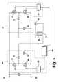
- an RF plasma supply device 1in which a plasma power for supplying a plasma load 2 is generated.
- the illustrated RF plasma supply device 1is connected via a network connection 3 to a power supply network, which may be single-phase or multi-phase.
- the power connector 3may be formed as a plug contact.
- the mains connection 3is connected to DC power supplies 4, 5. These are each assigned to an RF generator 6, 7 and supply it each with a direct current or DC voltage. Alternatively, a common DC power supply can be provided for both HF generators 6, 7. In each case an RF power signal is generated by the RF generators 6, 7, which is supplied to a coupling element 8 designed as a 90 ° hybrid.
- the RF power signalsare coupled in the coupling element 8 to a coupled RF power.
- the coupling element 8splits the coupled RF power to the outputs 9 and 11.
- a plasma power to be supplied to the plasma load 2is applied to the output 9, and an equalizing power to be supplied to a compensating load 10 is applied to the output 11.
- the coupled RF poweris split differently among the outputs 9, 11. An almost complete transfer of the coupled RF power to the output 9 takes place when the RF power signals of the RF generators 6, 7 are phase-shifted by 90 °.
- the core of the RF plasma supply device 1is a control and / or regulating device 12 which regulates and / or controls both the DC power supplies 4, 5 and the RF generators 6, 7.
- the control and / or regulationtakes place in such a way that during operation of the RF plasma supply device for a plasma power which is in the range between a lower power limit and a predetermined rated power, the majority of the coupled RF power to the output 9 and thus the plasma load 2 is given and only an insignificant part of the coupled RF power is given to the balancing load 10. In this operating range, the RF generators 6, 7 are operated between their lower power limit and their rated power.
- the signal level at the outputs of the RF generators 6, 7 by a control or regulation of the DC power supplies 4, 5are set.
- the HF generators 6, 7, which are designed as operating in switching mode RF generatorsare controlled by a phase-shift method to affect the level of the RF power signals.
- the RF generators 6, 7are controlled by the control and / or regulating device 12 such that the RF power signals have a phase position in which a predominant part of coupled RF power to the balancing load 10 is given and only a small part of the coupled RF power is given to the plasma load 2.
- measuring devices 13, 14, 15are provided for detecting quantities describing an RF power, which transfer the quantities to the control and / or regulating device 12, so that a regulation of one or more RF powers is made possible.
- the control and / or regulating device 12has a first controller 16, which is used for controlling the plasma power and the compensation power in a power range between the lower power limit and the rated power, and a second controller 17, for the power control in one below lying power range is used.
- an impedance matching 18is arranged between the output 9 and the plasma load 2.
- a DC power supply 22is connected to a mains connection 23.
- the DC power supply 22supplies three RF generators 24, 25, 26 with a DC and / or DC voltage.
- the RF power signals generated in the RF generators 24, 25are coupled in a first coupling element 27 to a first coupled RF power.
- a first portion of the coupled RF poweris passed to a second coupling link 28, while the remainder of the coupled RF power is applied to a first balancing load 29.
- the division of the coupled RF powerdepends on the phase position of the RF power signals generated by the RF generators 24, 25.
- the output power or the RF power signal output at the output of the first coupling element 27is coupled to the HF power generated in the HF generator 26 or from the RF power signal output therefrom, so that a second coupled RF power is produced.
- the second coupled RF poweris applied to a plasma power which is applied to the plasma load 2 via the output 30 of the second coupling element 28 and a compensation power, which is given via the output 31 to the second balancing load 32, divided.
- the control and / or regulating device 12controls or regulates in this case, the DC power supply 22 and the RF generators 24 - 26. Measuring devices are for reasons of clarity in the Fig. 2 not shown.
- the coupling member 28is disposed downstream of the coupling member 27. Thus, the coupling elements 27, 28 are cascaded.
- the RF generator 6is shown in detail.
- the RF generator 6has two parts 40, 41, which are arranged in accordance with a full bridge circuit.
- the circuit according to Fig. 3makes it possible to adjust the output 42 output by varying the phase between the switching signals applied to the two halves 40, 41.
- the first halfcomprises a pair of switching elements 43, 44 which receive a pair of switching signals output from a signal source 45.
- the switching elements 43, 44are in series between the negative and positive Terminals of the DC power supply 22 connected.
- the output of the switching elements 43, 44is connected to an inductance 46, which is part of an output resonant circuit.
- the output resonant circuitis formed by the inductor 46 and the capacitor 47.
- the output of the first half 40is connected to a first tap of a transformer 48.
- the second half 41comprises the switching elements 49, 50.
- a signal source 51outputs a pair of switching signals which are given to the switching elements 49, 50.
- the signal sources 45, 51can also be combined into a single unit.
- the second half 41also comprises an output resonant circuit with an inductor 52 and a capacitor 53.
- the second half 41is connected to the second tap of the transformer 48.
- the transformer 48By the transformer 48, a galvanic separation between the halves 40, 41 and the output 42 is achieved.
- the halves 40, 41are connected in series through the primary winding 54 of the transformer 48.
- the halves 40, 41are connected in series so that a change in phase between the switching signals driving each half 40, 41 varies the power at the output 42.
- the switching elements 43, 49are activated and deactivated at the same times, they work in phase.
- the switching element 43is always turned off when the switching element 49 is turned on and the switching element 43 is turned on whenever the switching element 49 is turned off, the switching elements are not in phase or 180 ° out of phase.
- the phase relationship between the halves 40, 41is determined by a phase control 60, wherein the phase control 60 may be part of the control and / or regulating device 12, in particular the controller 16.
- the phase controller 60controls the signal sources 45, 51 in order to set the phase offset or the phase position between the two halves 40, 41.
- a maximum power or level of the RF power signalis achieved at the output 42 when the halves 40, 41 are operated with a phase offset of 180 °.
- the lowest output poweris achieved when the halves 40, 41 are operated in phase. In this case, each half 40, 41 sees an open circuit independent of the load impedance.
- the basis of the Fig. 3 power setting described at the output 42is a power setting in the phase-shift method.
Landscapes
- Engineering & Computer Science (AREA)
- Physics & Mathematics (AREA)
- Plasma & Fusion (AREA)
- Chemical & Material Sciences (AREA)
- Analytical Chemistry (AREA)
- Power Engineering (AREA)
- Plasma Technology (AREA)
- Physical Vapour Deposition (AREA)
- Drying Of Semiconductors (AREA)
Abstract
Description
Translated fromGermanDie Erfindung betrifft ein Verfahren zum Steuern und/oder Regeln der Ausgangsleistung einer HF-Plasmaversorgungseinrichtung, umfassend die Verfahrensschritte:
- a. Erzeugen zumindest eines ersten und eines zweiten HF-Leistungssignals mittels jeweils eines HF-Generators;
- b. Kopplung zumindest zweier HF-Leistungssignale in Abhängigkeit der Phasenlage und/oder der Pegel (Amplituden) der HF-Leistungssignale zu einer gekoppelten HF-Leistung;
- c. Aufteilen der gekoppelten HF-Leistung auf eine einer Plasmalast zuzuführenden Plasmaleistung und eine einer Ausgleichslast zuzuführenden Ausgleichsleistung,
- a. Generating at least a first and a second RF power signal by means of a respective RF generator;
- b. Coupling of at least two RF power signals as a function of the phase position and / or the level (amplitudes) of the RF power signals to a coupled RF power;
- c. Dividing the coupled RF power into a plasma power to be supplied to a plasma load and a balancing power to be supplied to a balancing load,
Für Plasmaversorgungseinrichtungen und/oder die darin angeordneten HF-Generatoren werden vom Hersteller Nennleistungen angegeben, wobei die Summe der Nennleistungen der einzelnen HF-Generatoren die Nennleistung der Plasmaversorgungseinrichtung darstellt (Siehe z.B.
Es ist bekannt, dass HF-Generatoren und damit HF-Plasmaversorgungseinrichtungen bei einem Bruchteil ihrer Nennleistung nur sehr schwer betrieben werden können. Sie neigen zu unkontrollierten Schwingungen und lassen sich nur schwer auf eine genaue Ausgangsleistung regeln. Zumeist wird von Herstellern von HF-Generatoren auch eine untere Leistungsgrenze angegeben, unterhalb derer der HF-Generator nicht zuverlässig oder nicht mit der erforderlichen Genauigkeit betrieben werden kann. Diese kann z.B. 10% der Nennleistung betragen, sie kann aber auch bei niedrigeren Werten liegen, z.B. bei 1%. Die Summe der unteren Leistungsgrenzen der HF-Generatoren ergibt dabei in etwa die untere. Leistungsgrenze der Plasmaversorgungseinrichtung.It is known that HF generators and thus RF plasma supply devices can only be operated with great difficulty at a fraction of their nominal power. They are prone to uncontrolled vibrations and are difficult to control to an accurate output power. In most cases, manufacturers of RF generators also specify a lower power limit, below which the HF generator can not be operated reliably or with the required accuracy can. This can for example be 10% of the nominal power, but it can also be at lower values, for example at 1%. The sum of the lower power limits of the HF generators results in about the lower. Power limit of the plasma supply device.
Es ist bekannt, für den Betrieb der Plasmaversorgungseinrichtung unterhalb der unteren Leistungsgrenze einem zusätzlichen Widerstand einen ersten Teil der Leistung zuzuführen und den restlichen Teil der Leistung der Last zuzuführen und so den HF-Generator oberhalb dessen unterer Leistungsgrenze zu betreiben. Man kann dazu den Widerstand in Reihe oder parallel zur Last anschließen. Für kleine Leistungen unterhalb der unteren Leistungsgrenze bietet diese Lösung meist ein brauchbares Ergebnis. Dieser Widerstand muss, wenn die Leistung, die an die Last geliefert wird, in Richtung Nennbereich ansteigt, abgetrennt werden, da ihm sonst eine sehr hohe Leistung zugeführt würde, was große Verluste und einen hohen Kühlaufwand bedeuten würde. Da der Widerstand in den bekannten Ausführungen nicht regelbar ist, muss er schlagartig abgetrennt werden, ein kontinuierliches Durchfahren eines weiten Leistungsbereiches ist so nicht möglich.It is known for the operation of the plasma supply device below the lower power limit to supply a first part of the power to an additional resistor and to supply the remaining part of the power to the load and thus operate the HF generator above its lower power limit. You can do this by connecting the resistor in series or parallel to the load. For small power below the lower power limit, this solution usually provides a usable result. This resistance must be disconnected when the power supplied to the load increases towards the rated range, otherwise it would be given a very high power, which would result in large losses and high cooling requirements. Since the resistance is not adjustable in the known versions, it must be disconnected abruptly, a continuous driving through a wide power range is not possible.
Von HF-Plasmaversorgungseinrichtungen wird verlangt, dass sie sich in einem weiten Leistungsbereich sehr genau einstellen lassen. Dieser Leistungsbereich soll kontinuierlich durchfahren werden können.RF plasma power supplies are required to be very accurately tuned over a wide power range. This power range should be able to be passed continuously.
Aufgabe der vorliegenden Erfindung ist es daher, ein Verfahren und eine Vorrichtung bereitzustellen, mit denen diesbezüglich Abhilfe geschaffen werden kann.The object of the present invention is therefore to provide a method and a device which can be remedied in this regard.
Diese Aufgabe wird durch ein Verfahren der eingangs genannten Art gelöst, wobei eine Steuerung und/oder Regelung der Pegel und/oder der Phasenlage der HF-Leistungssignale derart erfolgt, dass für Plasmaleistungen im Bereich zwischen einer vorgegebenen unteren Leistungsgrenze und einer vorgegebenen Nennleistung ein unwesentlicher Teil der gekoppelten HF-Leistung die Ausgleichsleistung darstellt und für Plasmaleistungen unterhalb der vorgegebenen unteren Leistungsgrenze ein wesentlicher Teil der gekoppelten HF-Leistung die Ausgleichsleistung darstellt. Mit diesem Verfahren ist es möglich, eine Plasmaversorgungseinrichtung über einen weiten Leistungsbereich, insbesondere auch beim Betrieb unterhalb der unteren Leistungsgrenze, stabil zu betreiben. Ein großer Leistungsbereich kann ohne Probleme abgedeckt und im Wesentlichen kontinuierlich durchfahren werden. Dabei werden die HF-Leistungsgeneratoren vorzugsweise so angesteuert, dass alle in etwa dieselbe HF-Leistung abgeben.This object is achieved by a method of the aforementioned type, wherein a control and / or regulation of the level and / or the phase position of the RF power signals is such that for plasma power in the area represents an unessential part of the coupled RF power compensation power between a predetermined lower power limit and a given nominal power and represents a significant part of the coupled RF power balancing power for plasma power below the predetermined lower power limit. With this method, it is possible to operate a plasma supply device over a wide power range, especially when operating below the lower power limit, stable. A large power range can be covered without problems and passed through substantially continuously. In this case, the HF power generators are preferably controlled so that all deliver approximately the same RF power.
Eine Plasmalast kann eine Vakuumplasmabearbeitungskammer, z.B. zum Beschichten, Ätzen oder Bearbeiten von Substraten mittels eines Plasmas, bzw. ein darin ablaufender Plasmaprozess, oder eine Laseranregung in einem Gaslaser sein.A plasma load may comprise a vacuum plasma processing chamber, e.g. for coating, etching or processing substrates by means of a plasma, or a plasma process taking place therein, or a laser excitation in a gas laser.
Im Rahmen der Erfindung werden unter HF-Frequenzen Frequenzen im Bereich zwischen 1 und 30MHz verstanden. Bevorzugte Frequenzen bei Plasmalasten sind 13MHz und 27MHz.In the context of the invention, RF frequencies are understood to be frequencies in the range between 1 and 30 MHz. Preferred frequencies for plasma loads are 13MHz and 27MHz.
Vorzugsweise wird für Plasmaleistungen im Bereich zwischen einer vorgegebenen unteren Leistungsgrenze und einer vorgegebenen Nennleistung eine geringere Ausgleichsleistung eingestellt als für Plasmaleistungen unterhalb der vorgegebenen unteren Leistungsgrenze. Die untere Leistungsgrenze kann beispielsweise in Abhängigkeit von der Nennleistung vorgegeben werden. Beispielsweise kann als untere Leistungsgrenze eine Leistung im Bereich von 0,1% bis 20% der Nennleistung vorgegeben werden. Vorzugsweise wird die untere Leistungsgrenze als etwa 10% der Nennleistung vorgegeben.Preferably, for plasma powers in the range between a predetermined lower power limit and a predetermined rated power, a lower compensation power is set than for plasma powers below the predetermined lower power limit. The lower power limit can be specified, for example, depending on the rated power. For example, a power in the range of 0.1% to 20% of the rated power can be specified as the lower power limit. Preferably, the lower power limit is set at about 10% of the rated power.
Besonders bevorzugt ist eine Verfahrensvariante, bei der die Pegel und/oder Phasen der HF-Leistungssignale, insbesondere beim Betrieb der HF-Plasmaversorgungseinrichtung im Bereich der Nennleistung, eingestellt werden, indem die Gleichstrom- und/oder Gleichspannungsversorgung der HF-Leistungsgeneratoren gesteuert und/oder geregelt wird. Durch diese Vorgehensweise lässt sich der Pegel der Plasmaleistung, insbesondere in einem Leistungsbereich oberhalb der unteren Leistungsgrenze, besonders einfach einstellen. Im einfachsten Fall sind genau zwei HF-Generatoren und ein Koppelglied zur Addition der HF-Leistungssignale vorhanden. Die Nennleistung jedes HF-Generators beträgt beispielsweise 1,5kW, sie arbeiten beispielsweise beide bei 13,56MHz. Arbeitet die HF-Plasmaversorgungseinrichtung im Bereich >10% ihrer Nennleistung, so werden die Phasenlage und die Pegel der beiden HF-Generatoren so eingestellt, dass möglichst die gesamte gekoppelte HF-Leistung an die Plasmalast geliefert wird. Das sind bei Nennleistung dann 3kW. Die Leistungssteuerung erfolgt zum Beispiel durch die Steuerung der Gleichstrom- oder Gleichspannungszufuhr der HF-Generatoren. Arbeitet die HF-Plasmaversorgungseinrichtung im Bereich <10% ihrer Nennleistung, also kleiner 300W Plasmaleistung, so erfolgt die Steuerung der Plasmaleistung dann vorzugsweise nicht mehr zwingend durch die Steuerung der Pegel der HF-Leistungssignale der HF-Generatoren (beispielsweise durch Steuerung der Gleichspannungs- oder Gleichstromversorgung), sondern vorzugsweise überwiegend durch die Steuerung der Phasenlage der beiden HF-Generatoren zueinander.Particularly preferred is a variant of the method in which the levels and / or phases of the RF power signals, in particular during operation of the RF plasma supply device in the range of nominal power, are set by controlling the DC and / or DC power supply of the RF power generators and / or is regulated. By means of this procedure, the level of plasma power, in particular in a power range above the lower power limit, can be set particularly easily. In the simplest case, there are exactly two HF generators and a coupling element for adding the RF power signals. For example, the rated power of each RF generator is 1.5kW, for example, they both operate at 13.56MHz. If the RF plasma supply device operates in the range of> 10% of its nominal power, the phase position and the levels of the two HF generators are adjusted so that as far as possible the entire coupled RF power is delivered to the plasma load. These are at rated power then 3kW. The power control is performed, for example, by controlling the DC or DC power supply of the RF generators. If the RF plasma supply device operates in the range of <10% of its nominal power, ie less than 300 W plasma power, the control of the plasma power is then preferably no longer compulsorily controlled by the control of the levels of the RF power signals of the HF generators (for example by controlling the DC or DC power supply) DC power supply), but preferably predominantly by controlling the phase position of the two RF generators to each other.
Vorteilhafterweise werden die HF-Leistungssignale erzeugt, indem schaltende Elemente in den HF-Generatoren angesteuert werden. Im Schaltbetrieb arbeitende HF-Generatoren sind besonders verlustarm und werden deswegen für größere Leistungen bevorzugt eingesetzt. HF- Generatoren, die im Schaltbetrieb arbeiten, sind bekannt, z.B. Class-D (Vollbrücke oder Halbbrücke) oder Class-E, F Verstärker oder Mischformen davon. Diese Art von HF-Generatoren weisen einen oder mehrere schaltende Elemente und einen Ausgangskreis auf. Die schaltenden Elemente werden mit einem Schaltsignal einer Schaltfrequenz ein- und ausgeschaltet.Advantageously, the RF power signals are generated by controlling switching elements in the RF generators. HF generators operating in switching mode are particularly low-loss and are therefore preferred for greater power. HF generators that are in the Switching operation are known, for example, Class-D (full bridge or half bridge) or Class-E, F amplifier or mixed forms thereof. These types of RF generators have one or more switching elements and an output circuit. The switching elements are switched on and off with a switching signal of a switching frequency.
Der Ausgangskreis hat im Wesentlichen zwei Aufgaben: Erstens das Filtern des HF-Leistungssignals, so dass im Wesentlichen nur die Schaltfrequenz zum Ausgang gelangt. Zweitens soll er das verlustarme Schalten der schaltenden Elemente ermöglichen. Die Ausgangsleistung des einzelnen HF-Generators kann zum Beispiel durch die Gleichspannungs- oder Gleichstromzufuhr gesteuert werden. Die im Schaltbetrieb arbeitenden HF-Generatoren arbeiten bei Frequenzen oberhalb 1MHz üblicherweise mit MOSFETs als schaltenden Elementen. Diese MOSFETs haben eine Ausgangskapazität Coss, die nichtlinear von der Spannung am Ausgang des MOSFETs zwischen dem Drain und Source-Anschluss abhängig ist. Während die Kapazität für hohe Ausgangsspannungen (z.B. größer 100V) nur geringfügig mit zunehmender Spannung langsam abfällt, steigt die Kapazität bei niedrigen Ausgangsspannungen (z.B. kleiner 40V) bei fallenden Spannungen sehr stark an und kann um Potenzen (z.B. Faktor 100, 1000) größer werden, als der Wert bei großen Spannungen. Dies macht den Betrieb von im Schaltbetrieb arbeitenden HF-Generatoren bei kleinen Spannungen kompliziert, vor allem, wenn sie eigentlich für den Betrieb bei großen Spannungen ausgelegt sind, weil sich die Kapazität immer auf den Ausgangskreis der im Schaltbetrieb arbeitenden HF-Generatoren auswirkt. Ändert sich aber ein Wert in der Schaltung sehr stark, so verändert dies das Verhalten des Ausgangskreises und er kann seine beiden Aufgaben nicht mehr oder nicht mehr richtig wahrnehmen. Dadurch wird die Leistungseinstellung bei im Verhältnis zur Nennleistung niedrigen Ausgangsleistungen sehr kompliziert. Für viele Anwendungen bei Vakuumplasmaprozessen wird aber eine sehr exakte Leistungseinstellung über einen sehr weiten Leistungsbereich gefordert, insbesondere auch bei Leistungen, die sehr viel kleiner als die Nennleistung der HF-Plasmaversorgungseinrichtung sind. Ein zusätzliches Problem ist, dass die Änderung dC/dU bei kleinen Spannungen sehr groß ist. Das führt zu Nichtlinearitäten des Verhaltens des Ausgangskreises.Essentially, the output circuit has two functions: First, filtering the RF power signal so that essentially only the switching frequency reaches the output. Second, it should enable the low-loss switching of the switching elements. The output power of the single RF generator can be controlled by the DC or DC supply, for example. The HF generators operating in switching mode usually operate with MOSFETs as switching elements at frequencies above 1 MHz. These MOSFETs have an output capacitance Coss that is non-linearly dependent on the voltage at the output of the MOSFET between the drain and source terminals. While the capacity for high output voltages (eg greater than 100V) decreases only slightly with increasing voltage, the capacitance at low output voltages (eg less than 40V) increases very strongly with falling voltages and can increase by powers (eg factor 100, 1000), as the value at high voltages. This complicates the operation of high frequency switching RF generators at low voltages, especially when they are designed to operate at high voltages, because the capacitance always affects the output circuit of the RF generators operating in switching mode. However, if a value in the circuit changes very much, this changes the behavior of the output circuit and it can no longer or no longer properly perceive its two tasks. As a result, the power setting becomes very complicated at low output powers relative to the rated power. For many applications in vacuum plasma processes but is a very accurate power setting demanded over a very wide power range, especially for services that are much smaller than the rated power of the RF plasma supply device. An additional problem is that the change dC / dU is very large at low voltages. This leads to nonlinearities of the behavior of the output circle.
Mit dieser Erklärung ist klar, dass der Wert für die untere Leistungsgrenze im Regelfall nicht fest bei 10% der Nennleistung liegt, sondern sich in Abhängigkeit der gewünschten Nennleistung und der gewünschten niedrigsten einzustellenden Leistung im Bereich von 0,1% bis 20% der Nennleistung ändern kann. Maßgebend bei im Schaltbetrieb arbeitenden HF-Generatoren ist die Nichtlinearität der Ausgangskapazität und die Toleranz der Schaltung, die auch abhängt von der maximalen Spannung am schaltenden Element, der Frequenz, der Leistung etc.With this explanation, it is clear that the value for the lower power limit is usually not fixed at 10% of the nominal power, but varies in the range of 0.1% to 20% of the rated power depending on the desired rated power and the desired lowest power to be set can. Decisive for operating in switching mode RF generators is the non-linearity of the output capacitance and the tolerance of the circuit, which also depends on the maximum voltage at the switching element, the frequency, the power, etc.
Auf besonders einfache Art und Weise können die Pegel und/oder Phasen der HF-Leistungssignale eingestellt werden, indem die schaltenden Elemente in einem Phase-Shift-Verfahren angesteuert werden. Beispielsweise kann ein HF-Generator zwei Halbbrücken aufweisen, die jeweils aus zwei wechselseitig schaltenden Elementen bestehen. Durch die Ansteuerung der schaltenden Elemente werden die Phasenlage der Halbbrücken und damit die Leistung am Ausgang des HF-Generators eingestellt. Auch bei diesem Prinzip der Leistungsregelung können sehr kleine Leistungen nur noch unzureichend genau eingestellt werden. Die Steuerung und/oder Regelung der einer Ausgleichslast zuzuführenden Leistung ist also auch bei dieser Art der Erzeugung der HF-Leistungssignale vorteilhaft, um die gesamte HF-Plasmaversorgungseinrichtung zuverlässig betreiben zu können.In a particularly simple manner, the levels and / or phases of the RF power signals can be adjusted by the switching elements are driven in a phase-shift method. For example, an RF generator may have two half-bridges, each consisting of two mutually switching elements. By controlling the switching elements, the phase angle of the half-bridges and thus the power at the output of the HF generator are set. Even with this principle of power control very small power can be adjusted only insufficiently accurate. The control and / or regulation of the power to be supplied to a compensating load is therefore also advantageous in the case of this type of generation of the HF power signals in order to be able to reliably operate the entire RF plasma supply device.
Besonders bevorzugt ist es, wenn eine Grobeinstellung der gekoppelten HF-Leistung erfolgt, indem die Gleichstrom- und/oder Gleichspannungsversorgung der HF-Generatoren gesteuert und/oder geregelt wird, eine Feineinstellung der gekoppelten HF-Leistung erfolgt, indem eine Phase-Shift-Steuerung der HF-Generatoren erfolgt. Dadurch ist es möglich, für den Betrieb der HF-Plasmaversorgungseinrichtung sowohl unterhalb als auch oberhalb der unteren Leistungsgrenze die Plasmaleistung mit einer sehr großen Genauigkeit einzustellen. Zusätzlich ist es möglich, einzelne HF-Generatoren abzuschalten und die verbleibenden HF-Generatoren oberhalb ihrer eigenen unteren Leistungsgrenze zu betreiben. Insbesondere ist es möglich, die Ausgangsleistung der HF-Plasmaversorgungseinrichtung beim Betrieb unterhalb der unteren Leistungsgrenze ausschließlich über die Leistungsaufteilung einzustellen.It is particularly preferred, when a coarse adjustment of the coupled RF power is performed by the DC and / or DC power supply of the RF generators controlled and / or regulated, a fine adjustment of the coupled RF power is performed by a phase-shift control the HF generators takes place. This makes it possible to set the plasma power with a very high accuracy for the operation of the RF plasma power supply both below and above the lower power limit. In addition, it is possible to switch off individual HF generators and to operate the remaining HF generators above their own lower power limit. In particular, it is possible to adjust the output power of the RF plasma supply device during operation below the lower power limit exclusively via the power distribution.
Bei einer vorteilhaften Verfahrensvariante kann vorgesehen sein, dass die HF-Leistungssignale in einem 90° Hybrid, insbesondere in einem 3dB-Koppler, gekoppelt werden. Durch den Einsatz von diesen Kopplern können Mehrfachreflexionen bei Fehlanpassung an der Plasmalast vermieden werden. Dies bedeutet, dass die dem 90° Hybrid vorgeschalteten Generatoren wirksam geschützt werden. Außerdem wird durch einen 90° Hybrid eine Leistungsregelung bei geringen Leistungen ermöglicht. Bei einigen Leistungskopplern, wie zum Beispiel den 90° Hybriden, bedeutet eine Kopplung der HF-Leistungs(eingangs)signale eine Addition der HF-Leistungssignale zu einer addierten HF-Leistung als gekoppelter HF-Leistung. Die addierte HF-Leistung wird dann je nach Pegel und/oder Phasenlage der HF-Leistungssignale auf zwei HF-Leistungs(ausgangs)signale aufgeteilt.In an advantageous variant of the method it can be provided that the RF power signals are coupled in a 90 ° hybrid, in particular in a 3dB coupler. Through the use of these couplers multiple reflections can be avoided in case of mismatch at the plasma load. This means that the generators upstream of the 90 ° hybrid are effectively protected. In addition, a 90 ° hybrid enables power control at low power levels. For some power couplers, such as the 90 ° hybrids, coupling the RF power (input) signals means adding the RF power signals to an added RF power as a coupled RF power. The added RF power is then divided depending on the level and / or phase of the RF power signals on two RF power (output) signals.
Größere Plasmaleistungen können erzeugt werden, wenn mehr als zwei HF-Leistungssignale erzeugt werden, wobei jeweils zwei HF-Leistungssignale zu einem gekoppelten HF-Leistungssignal gekoppelt werden. Die Kopplung bzw. Addition der HF-Leistungssignale erfolgt vorzugsweise in einem Koppelglied, so dass vorteilhafterweise auch mehrere Ausgleichslasten vorgesehen sind und entsprechend mehrere Ausgleichsleistungen erzeugt werden. Dabei werden in den Koppelgliedern vorzugsweise jeweils zwei HF-Leistungssignale gekoppelt. Mehrere Koppelglieder können kaskadiert werden, so dass am Ende der Kaskade ein HF-Leistungssignal erzeugt wird, welches die einer Plasmalast zuzuführenden Plasmaleistung darstellt.Greater plasma power may be generated when generating more than two RF power signals, with two RF power signals each being coupled to a coupled RF power signal. The coupling or addition of the RF power signals is preferably carried out in a coupling element, so that advantageously also a plurality of balancing loads are provided and a plurality of equalization powers are generated accordingly. In each case two RF power signals are preferably coupled in the coupling links. Several coupling elements can be cascaded, so that at the end of the cascade, an RF power signal is generated, which represents the plasma power to be supplied to a plasma load.
Vorteilhafterweise wird zumindest eine eine HF-Leistung beschreibende Größe gemessen. Dabei ist es denkbar, die HF-Leistungssignale oder diese beschreibende Größen am Ausgang zumindest eines HF-Generators zu messen. Alternativ oder zusätzlich kann eine die Plasmaleistung und/oder die Ausgleichsleistung beschreibende Größe erfasst werden. Als eine HF-Leistung beschreibende Größe kann entweder die Leistung selbst oder eine Spannung und/oder ein Strom erfasst werden.Advantageously, at least one variable describing an RF power is measured. It is conceivable to measure the RF power signals or these descriptive quantities at the output of at least one HF generator. Alternatively or additionally, a variable describing the plasma power and / or the compensation power can be detected. As a quantity describing an RF power, either the power itself or a voltage and / or a current can be detected.
Bei einer Verfahrensvariante kann vorgesehen sein, dass die die HF-Leistung beschreibende Größe zur Regelung der gemessenen HF-Leistung oder einer anderen HF-Leistung verwendet wird. So kann beispielsweise eine in einem HF-Generator gemessene Größe verwendet werden, um die von diesem Generator abgegebene HF-Leistung zu regeln. Weiterhin ist es denkbar, dass die erfasste Plasmaleistung verwendet wird, um die HF-Leistung eines oder mehrerer HF-Generatoren zu regeln. Die gemessenen eine HF-Leistung beschreibende Größen werden dabei vorzugsweise einer Steuer - und/oder Regeleinrichtung zugeführt.In one variant of the method, provision may be made for the variable describing the RF power to be used to control the measured RF power or another RF power. For example, a variable measured in an RF generator can be used to control the RF power delivered by that generator. Furthermore, it is conceivable that the detected plasma power is used to control the RF power of one or more RF generators. The measured variables describing an RF power are preferably supplied to a control and / or regulating device.
Bei einer Ausgestaltung der Erfindung kann vorgesehen sein, dass eine Impedanzanpassung durchgeführt wird. Die Impedanzanpassung wird vorzugsweise zwischen der Plasmalast und der Plasmaversorgungseinrichtung durchgeführt.In one embodiment of the invention, it can be provided that an impedance matching is performed. The impedance matching is preferably performed between the plasma load and the plasma supply device.
In den Rahmen der Erfindung fällt außerdem eine HF-Plasmaversorgungseinrichtung zur Versorgung einer Plasmalast mit Plasmaleistung, umfassend zumindest zwei HF-Generatoren zur Erzeugung eines ersten und zweiten HF-Leistungssignals, und zumindest ein Koppelglied, in dem aus zwei HF-Leistungssignalen eine gekoppelte HF-Leistung erzeugt wird, wobei an das zumindest eine Koppelglied die Plasmalast und eine Ausgleichslast anschließbar oder angeschlossen sind, und mit einer Steuer- und/oder Regeleinrichtung, die die HF-Generatoren steuert und/oder regelt, wobei die Steuer- und/oder Regeleinrichtung zur Durchführung des vorher beschriebenen Verfahrens und/oder seiner Verfahrensvarianten eingerichtet ist. Mit einer solchen Vorrichtung lassen sich die oben beschriebenen Vorteile erreichen.The scope of the invention also includes an RF plasma supply device for supplying a plasma load with plasma power, comprising at least two HF generators for generating a first and second RF power signal, and at least one coupling element, in which a paired RF signal is generated from two RF power signals. Power is generated, wherein the at least one coupling element, the plasma load and a balancing load are connected or connected, and with a control and / or regulating device which controls the RF generators and / or regulated, the control and / or regulating device for Implementation of the previously described method and / or its variants of the method is set up. With such a device, the advantages described above can be achieved.
Besonders bevorzugt ist es dabei, wenn das Verfahren in Hardware, Firmware und/oder Software implementiert ist. Der Vorteil einer Implementierung in Hardware liegt darin, dass eine schnelle, stufenlose Leistungsregelung erfolgen kann. Bei einer Implementierung in Firmware oder Software ist die Steuerung beziehungsweise Regelung leicht konfigurierbar, zuverlässig und kostengünstig bei geringem Pflegeaufwand einstellbar.It is particularly preferred if the method is implemented in hardware, firmware and / or software. The advantage of an implementation in hardware is that a fast, stepless power control can take place. In an implementation in firmware or software, the control or regulation is easily configurable, reliable and inexpensive adjustable with low maintenance costs.
Bei einer vorteilhaften Ausführungsform weist die Steuer- und/oder Regeleinrichtung eine erste Steuerung zur Steuerung der Leistungsaufteilung für gekoppelte HF-Leistungen oberhalb der unteren Leistungsgrenze und eine zweite Steuerung für eine Steuerung der Leistungsaufteilung für gekoppelte HF-Leistungen unterhalb der unteren Leistungsgrenze auf. Die erste Steuerung kann dabei insbesondere für die Steuerung der Gleichstromversorgung der HF-Generatoren und/oder eine Phase-Shift-Steuerung wirksam sein und die zweite Steuerung kann für die Steuerung der Phasenlage der HF-Generatoren wirksam sein.In an advantageous embodiment, the control and regulation device has a first controller for controlling the power split for coupled RF power above the lower power limit and a second controller for controlling the power split for coupled RF power below the lower power limit. The first control can be effective in particular for the control of the DC power supply of the RF generators and / or a phase-shift control and the second control can be effective for the control of the phase position of the RF generators.
Dabei kann vorgesehen sein, dass die zweite Steuerung einen wesentlichen Anteil der gekoppelten HF-Leistung auf die Ausgleichslast aufteilt, der insbesondere über 10%, vorzugsweise über 20% der gekoppelten HF-Leistung liegt.It can be provided that the second controller divides a significant portion of the coupled RF power to the balancing load, which is more than 10%, preferably more than 20% of the coupled RF power.
Besonders bevorzugt ist es, wenn das Koppelglied als 90° Hybrid, insbesondere als 3dB-Koppler ausgebildet ist. Mit einem derartigen Koppelglied kann das eingangs beschriebene Hinzuschalten und Abtrennen eines Widerstands entfallen. Weiterhin können durch einen 90°-Hybrid sich negativ auf die HF-Generatoren auswirkende Mehrfachreflexionen vermieden werden.It is particularly preferred if the coupling member is designed as a 90 ° hybrid, in particular as a 3dB coupler. With such a coupling element, the switching-on and disconnection of a resistor described above can be dispensed with. Furthermore, can be avoided by a 90 ° hybrid negative impact on the RF generators multiple reflections.
Ein größeres Leistungsspektrum kann abgedeckt und höhere Nennleistungen können erzielt werden, wenn mehr als zwei HF-Generatoren und zumindest zwei, insbesondere kaskadierte, Koppelglieder vorgesehen sind. Zudem erhöht sich die Störunterdrückung bei Fehlanpassung an der Plasmalast mit jeder Kaskade von 90° Hybriden um ein Vielfaches.A larger power spectrum can be covered and higher power ratings can be achieved if more than two RF generators and at least two, in particular cascaded, coupling members are provided. In addition, interference suppression on plasma parasitic mismatch increases many times over with each cascade of 90 ° hybrids.
Wenn zumindest eine Messeinrichtung zur Messung einer eine HF-Leistung beschreibenden Größe vorgesehen ist, kann nicht nur eine Steuerung der Leistung anhand vorgegebener Leistungswerte sondern auch eine Regelung erfolgen, da eine Rückkopplung möglich wird. Die Messeinrichtungen stehen daher vorzugsweise mit der Steuer- und/oder Regeleinrichtung in Verbindung.If at least one measuring device is provided for measuring a quantity describing an RF power, not only can the power be controlled on the basis of predetermined power values but also a closed-loop control, since feedback becomes possible. The measuring devices are therefore preferably in communication with the control and / or regulating device.
In weiterer bevorzugter Ausgestaltung der Erfindung kann zumindest eine DC-Stromversorgung für die HF-Generatoren vorgesehen sein, die durch die Steuer- und/oder Regeleinrichtung gesteuert und/oder geregelt ist. Dadurch lassen sich die Pegel der HF-Leistungssignale besonders einfach einstellen. Dabei kann eine DC - Stromversorgung für mehrere HF-Generatoren vorgesehen sein oder es kann für jeden HF-Generator eine eigene DC-Stromversorgung vorgesehen sein.In a further preferred embodiment of the invention, at least one DC power supply can be provided for the HF generators, which is controlled and / or regulated by the control and / or regulating device. This makes it particularly easy to set the levels of the RF power signals. In this case, a DC power supply for several RF generators provided or it can be provided for each RF generator its own DC power supply.
Weitere Merkmale und Vorteile der Erfindung ergeben sich aus der nachfolgenden Beschreibung von Ausführungsbeispielen der Erfindung, anhand der Fig.en der Zeichnung, die erfindungswesentliche Einzelheiten zeigen, und aus den Ansprüchen. Die einzelnen Merkmale können je einzeln für sich oder zu mehreren in beliebiger Kombination bei einer Variante der Erfindung verwirklicht sein.Further features and advantages of the invention will become apparent from the following description of exemplary embodiments of the invention, with reference to the Fig.en the drawing, the invention essential details show, and from the claims. The individual features can be realized individually for themselves or for several in any combination in a variant of the invention.
Bevorzugte Ausführungsbeispiele der Erfindung sind in der Zeichnung schematisch dargestellt und werden nachfolgend mit Bezug zu den Fig.en der Zeichnung näher erläutert. Es zeigt:
- Fig. 1
- eine erste Ausführungsform einer erfindungsgemäßen HF-Plasmaversorgungseinrichtung;
- Fig. 2
- eine zweite Ausführungsform einer HF-Plasmaversorgungseinrichtung;
- Fig. 3
- eine Darstellung eines HF-Generators zur Verdeutlichung einer Phase-Shift-Steuerung.
- Fig. 1
- A first embodiment of an RF plasma supply device according to the invention;
- Fig. 2
- a second embodiment of an RF plasma supply device;
- Fig. 3
- a representation of an RF generator to illustrate a phase-shift control.
In der
Das Kernstück der HF-Plasmaversorgungseinrichtung 1 ist eine Steuer - und/oder Regeleinrichtung 12, die sowohl die Gleichstromversorgungen 4, 5 als auch die HF-Generatoren 6, 7 regelt und/oder steuert. Die Steuerung und/oder Regelung erfolgt dabei derart, dass beim Betrieb der HF-Plasmaversorgungseinrichtung für eine Plasmaleistung, die im Bereich zwischen einer unteren Leistungsgrenze und einer vorgegebenen Nennleistung liegt, der überwiegende Teil der gekoppelten HF-Leistung an den Ausgang 9 und somit die Plasmalast 2 gegeben wird und nur ein unwesentlicher Teil der gekoppelten HF-Leistung an die Ausgleichslast 10 gegeben wird. In diesem Betriebsbereich werden auch die HF-Generatoren 6, 7 zwischen ihrer unteren Leistungsgrenze und ihrer Nennleistung betrieben. Zu diesem Zweck kann der Signalpegel an den Ausgängen der HF-Generatoren 6, 7 durch eine Steuerung beziehungsweise Regelung der Gleichstromversorgungen 4, 5 eingestellt werden. Alternativ oder zusätzlich können die HF-Generatoren 6, 7, die als im Schaltbetrieb arbeitende HF-Generatoren ausgebildet sind, im Wege eines Phase-Shift-Verfahrens angesteuert werden, um den Pegel der HF-Leistungssignale zu beeinflussen.The core of the RF
Beim Betrieb der HF-Plasmaversorgungseinrichtung 1 in einem Leistungsbereich unterhalb der unteren Leistungsgrenze können die HF-Generatoren 6, 7 durch die Steuer - und/oder Regeleinrichtung 12 derart angesteuert werden, dass die HF-Leistungssignale eine Phasenlage aufweisen, bei der ein überwiegender Teil der gekoppelten HF-Leistung an die Ausgleichslast 10 gegeben wird und nur ein geringer Teil der gekoppelten HF-Leistung an die Plasmalast 2 gegeben wird.When operating the RF
Im gezeigten Ausführungsbeispiel sind Messeinrichtungen 13, 14, 15 zur Erfassung von eine HF-Leistung beschreibenden Größen vorgesehen, die die Größen an die Steuer - und/oder Regeleinrichtung 12 übergeben, so dass eine Regelung einer oder mehrerer HF-Leistungen ermöglicht wird. Die Steuer - und/oder Regeleinrichtung 12 weist im Ausführungsbeispiel eine erste Steuerung 16 auf, die zur Steuerung der Plasmaleistung und der Ausgleichsleistung in einem Leistungsbereich zwischen der unteren Leistungsgrenze und der Nennleistung verwendet wird und eine zweite Steuerung 17, die für die Leistungsregelung in einem darunter liegenden Leistungsbereich verwendet wird. Zwischen dem Ausgang 9 und der Plasmalast 2 ist eine Impedanzanpassung 18 angeordnet.In the exemplary embodiment shown, measuring
Bei der HF-Plasmaversorgungseinrichtung 21 der
Die Steuer - und/oder Regeleinrichtung 12 steuert beziehungsweise regelt in diesem Fall die Gleichstromversorgung 22 und die HF-Generatoren 24 - 26. Messeinrichtungen sind aus Übersichtlichkeitsgründen in der
In der
Die zweite Hälfte 41 umfasst die schaltenden Elemente 49, 50. Eine Signalquelle 51 gibt ein Paar von Schaltsignalen aus, die an die schaltenden Elemente 49,50 gegeben werden. Die Signalquellen 45, 51 können auch zu einer einzigen Einheit vereint werden.The second half 41 comprises the switching
Auch die zweite Hälfte 41 umfasst einen Ausgangsschwingkreis mit einer Induktivität 52 und einer Kapazität 53. Die zweite Hälfte 41 ist mit der zweiten Anzapfung des Übertragers 48 verbunden. Durch den Übertrager 48 wird eine galvanische Trennung zwischen den Hälften 40, 41 und dem Ausgang 42 erzielt. Die Hälften 40, 41 sind durch die Primärwicklung 54 des Übertragers 48 in Serie geschaltet.The second half 41 also comprises an output resonant circuit with an
Die Hälften 40, 41 sind in Serie geschaltet, so dass eine Veränderung der Phase zwischen den Schaltsignalen, die jede Hälfte 40, 41 ansteuern, die Leistung am Ausgang 42 variiert. Wenn die schaltenden Elemente 43, 49 zu den gleichen Zeitpunkten aktiviert und deaktiviert werden, arbeiten diese in Phase. Wenn dagegen das schaltende Element 43 immer dann ausgeschaltet ist, wenn das schaltende Element 49 eingeschaltet ist und das schaltende Element 43 immer dann eingeschaltet ist, wenn das schaltende Element 49 ausgeschaltet ist, sind die schaltenden Elemente nicht in Phase beziehungsweise um 180° phasenversetzt.The
Die Phasenlage zwischen den Hälften 40, 41 wird durch eine Phasensteuerung 60 bestimmt, wobei die Phasensteuerung 60 Teil der Steuer - und/oder Regeleinrichtung 12, insbesondere der Steuerung 16, sein kann. Die Phasensteuerung 60 steuert die Signalquellen 45, 51 an, um den Phasenversatz beziehungsweise die Phasenlage zwischen den beiden Hälften 40, 41 einzustellen. Eine maximale Leistung beziehungsweise ein maximaler Pegel des HF-Leistungssignals wird am Ausgang 42 erzielt, wenn die Hälften 40, 41 mit einem Phasenversatz von 180° betrieben werden. Die geringste Ausgangsleistung wird erzielt, wenn die Hälften 40, 41 in Phase betrieben werden. In diesem Fall sieht jede Hälfte 40, 41 einen Leerlauf unabhängig von der Lastimpedanz. Die anhand der
Claims (19)
- Method for controlling and/or regulating the power output of an RF plasma supply device (1, 21), comprising the method steps of:a. producing at least a first and a second RF power signal by means of a respective RF generator (6, 7, 24 - 26);b. coupling at least two RF power signals to a coupled RF power in dependance on the phase position and/or the levels of the RF power signals;c. distributing the coupled RF power between a plasma power which is to be supplied to a plasma load (2) and an equalising power which is to be supplied to an equalising load (10, 32),
characterised byd. controlling and/or regulating the levels and/or the phase position of the RF power signals in such a manner that, for plasma power in the range between a predefined lower power limit and a predefined nominal power, an insignificant portion of the coupled RF power constitutes the equalising power and, for plasma power below the predefined lower power limit, a significant portion of the coupled RF power constitutes the equalising power. - Method according to claim 1,characterised in that, for plasma power in the range between a predefined lower power limit and a predefined nominal power, a lower equalising power is set than for plasma power below the predefined lower power limit.
- Method according to claim 1 or 2,characterised in that the levels and/or phases of the RF power signals, in particular when the RF plasma supply device (1,21) is operated in the range of the nominal power, are adjusted by the direct current and/or direct voltage supply of.the RF power generators (6, 7, 24 - 26) being controlled and/or regulated.
- Method according to any one of the preceding claims,characterised in that the RF power signals are produced by driving switching elements (43, 44, 49, 50) in the RF generators (6, 7, 24 - 26).
- Method according to claim 4,characterised in that the levels and/or phases of the RF power signals are adjusted by driving the switching elements (43, 44, 49, 50) in a phase-shift method.
- Method according to any one of the preceding claims,characterised in that a coarse adjustment of the coupled RF power is carried out by controlling and/or regulating the direct current and/or the direct voltage supply of the RF generators (6, 7, 24 - 26) and a fine adjustment of the coupled RF power is carried out by carrying out a phase-shift control operation of the RF generators (6, 7, 24 - 26).
- Method according to any one of the preceding claims,characterised in that the RF power signals are coupled in a 90° hybrid, in particular in a 3dB coupler.
- Method according to any one of the preceding claims,characterised in that more than two RF power signals are produced, two RF power signals being coupled to a coupled RF power signal in each case.
- Method according to any one of the preceding claims,characterised in that a plurality of equalising power levels are produced for a plurality of equalising loads (29, 32).
- Method according to any one of the preceding claims,characterised in that the addition of RF power signals is carried out in coupling members (8,:27, 28), a plurality of coupling members (27, 28) being arranged in a cascading manner.
- Method according to any one of the preceding claims,characterised in that a variable is measured which describes an RF power.
- Method according to claim 11,characterised in that the variable which describes the RF power is used to regulate the measured RF power or another RF power.
- Method according to any one of the preceding claims,characterised in that an impedance matching operation is carried out.
- RF plasma supply device (1, 21) for supplying a plasma load (2) with plasma power, comprising at least two RF generators (6, 7, 24 - 26) for producing a first and a second RF power signal, and at least one coupling member (8, 27, 28) in which a coupled RF power is produced from two RF power signals, the plasma load (2) and an equalising load (10, 32) being connected or being able to be connected to the at least one coupling member (8, 28), and having a control and/or regulation device (12) which controls and/or regulates the RF generators (6, 7, 24 - 26),characterised in that the control and/or regulation device (12) is configured to carry out the method according to any one of the preceding claims.
- RF plasma supply device according to claim 14,characterised in that the method is implemented in hardware, firmware and/or software.
- RF plasma supply device according to either of the preceding claims 14 or 15,characterised in that the coupling member (8, 27, 28) is embodied as a 90° hybrid, in particular as a 3dB coupler.
- RF plasma power supply device according to any one of the preceding claims 14 to 16,characterised in that there are provided more than two RF generators (6, 7, 24 - 26) and at least two coupling members (27, 28) which are in particular arranged in a cascading manner.
- RF plasma supply device according to any one of the preceding claims 14 to 17,characterised in that at least one measuring device (13 - 15) is provided for measuring a variable which describes an RF power.
- RF plasma supply device according to any one of the preceding claims 14 to 18,characterised in that at least one DC power supply (4, 5, 22) is provided for the RF generators (6, 7, 24 - 6) and is controlled and/or regulated by the control and/or regulation device (12).
Priority Applications (7)
| Application Number | Priority Date | Filing Date | Title |
|---|---|---|---|
| AT05022558TATE392742T1 (en) | 2005-10-17 | 2005-10-17 | HF PLASMA SUPPLY DEVICE |
| EP20050022558EP1783904B1 (en) | 2005-10-17 | 2005-10-17 | HF plasma supply system |
| DE200550003768DE502005003768D1 (en) | 2005-10-17 | 2005-10-17 | RF plasma supply device |
| KR1020060100279AKR100842243B1 (en) | 2005-10-17 | 2006-10-16 | Method for controlling or regulating the power output of an rf plasma supply device and rf plasma supply device |
| US11/549,773US7745955B2 (en) | 2005-10-17 | 2006-10-16 | RF plasma supply device |
| CN2006101309893ACN101056495B (en) | 2005-10-17 | 2006-10-17 | High frequency plasma source device |
| JP2006282962AJP4755566B2 (en) | 2005-10-17 | 2006-10-17 | Method for open-loop control and / or closed-loop control of output energy of high-frequency plasma supply device, and high-frequency plasma supply device for supplying plasma energy to plasma load |
Applications Claiming Priority (1)
| Application Number | Priority Date | Filing Date | Title |
|---|---|---|---|
| EP20050022558EP1783904B1 (en) | 2005-10-17 | 2005-10-17 | HF plasma supply system |
Publications (2)
| Publication Number | Publication Date |
|---|---|
| EP1783904A1 EP1783904A1 (en) | 2007-05-09 |
| EP1783904B1true EP1783904B1 (en) | 2008-04-16 |
Family
ID=36581650
Family Applications (1)
| Application Number | Title | Priority Date | Filing Date |
|---|---|---|---|
| EP20050022558Expired - LifetimeEP1783904B1 (en) | 2005-10-17 | 2005-10-17 | HF plasma supply system |
Country Status (7)
| Country | Link |
|---|---|
| US (1) | US7745955B2 (en) |
| EP (1) | EP1783904B1 (en) |
| JP (1) | JP4755566B2 (en) |
| KR (1) | KR100842243B1 (en) |
| CN (1) | CN101056495B (en) |
| AT (1) | ATE392742T1 (en) |
| DE (1) | DE502005003768D1 (en) |
Cited By (1)
| Publication number | Priority date | Publication date | Assignee | Title |
|---|---|---|---|---|
| US10176970B2 (en) | 2015-02-10 | 2019-01-08 | Trumpf Huettinger Gmbh + Co. Kg | Redundant Power Supply System for a plasma process |
Families Citing this family (62)
| Publication number | Priority date | Publication date | Assignee | Title |
|---|---|---|---|---|
| KR100799175B1 (en)* | 2006-04-21 | 2008-02-01 | 주식회사 뉴파워 프라즈마 | Plasma Processing System and Control Method thereof |
| KR100915613B1 (en)* | 2007-06-26 | 2009-09-07 | 삼성전자주식회사 | Pulse Plasma Matching System and Method |
| US8528498B2 (en)* | 2007-06-29 | 2013-09-10 | Lam Research Corporation | Integrated steerability array arrangement for minimizing non-uniformity |
| US9105449B2 (en)* | 2007-06-29 | 2015-08-11 | Lam Research Corporation | Distributed power arrangements for localizing power delivery |
| US20090000738A1 (en)* | 2007-06-29 | 2009-01-01 | Neil Benjamin | Arrays of inductive elements for minimizing radial non-uniformity in plasma |
| EP2097920B1 (en) | 2007-07-23 | 2017-08-09 | TRUMPF Hüttinger GmbH + Co. KG | Plasma supply device |
| US20100123502A1 (en)* | 2008-07-09 | 2010-05-20 | Bhutta Imran A | System for providing a substantially uniform potential profile |
| ATE545946T1 (en)* | 2008-12-23 | 2012-03-15 | Huettinger Elektronik Gmbh | MEASURING METHOD AND MEASURING DEVICE FOR A PLASMA SUPPLY DEVICE |
| US7825719B2 (en)* | 2008-12-29 | 2010-11-02 | Advanced Energy Industries, Inc. | System and method for wideband phase-adjustable common excitation |
| CN202930354U (en)* | 2009-02-13 | 2013-05-08 | 许廷格电子两合公司 | Plasma supply device |
| KR101051048B1 (en) | 2009-03-03 | 2011-07-22 | 서용운 | Plasma generator integrating the final output terminal of power supply and plasma generating electrode |
| US9197196B2 (en)* | 2012-02-22 | 2015-11-24 | Lam Research Corporation | State-based adjustment of power and frequency |
| US10821542B2 (en) | 2013-03-15 | 2020-11-03 | Mks Instruments, Inc. | Pulse synchronization by monitoring power in another frequency band |
| DE102013226511B4 (en)* | 2013-12-18 | 2016-12-15 | TRUMPF Hüttinger GmbH + Co. KG | Power supply system and method for generating a power |
| DE102013226537B4 (en) | 2013-12-18 | 2022-12-29 | TRUMPF Hüttinger GmbH + Co. KG | Power supply system with multiple amplifier paths and method for exciting a plasma |
| US9844127B2 (en) | 2014-01-10 | 2017-12-12 | Reno Technologies, Inc. | High voltage switching circuit |
| US9196459B2 (en) | 2014-01-10 | 2015-11-24 | Reno Technologies, Inc. | RF impedance matching network |
| US9865432B1 (en) | 2014-01-10 | 2018-01-09 | Reno Technologies, Inc. | RF impedance matching network |
| US9755641B1 (en) | 2014-01-10 | 2017-09-05 | Reno Technologies, Inc. | High speed high voltage switching circuit |
| US10431428B2 (en) | 2014-01-10 | 2019-10-01 | Reno Technologies, Inc. | System for providing variable capacitance |
| US9697991B2 (en) | 2014-01-10 | 2017-07-04 | Reno Technologies, Inc. | RF impedance matching network |
| US10455729B2 (en) | 2014-01-10 | 2019-10-22 | Reno Technologies, Inc. | Enclosure cooling system |
| US9496122B1 (en) | 2014-01-10 | 2016-11-15 | Reno Technologies, Inc. | Electronically variable capacitor and RF matching network incorporating same |
| DE102014212439A1 (en) | 2014-06-27 | 2015-12-31 | TRUMPF Hüttinger GmbH + Co. KG | Method of operating a power generator and power generator |
| US11017983B2 (en) | 2015-02-18 | 2021-05-25 | Reno Technologies, Inc. | RF power amplifier |
| US9729122B2 (en) | 2015-02-18 | 2017-08-08 | Reno Technologies, Inc. | Switching circuit |
| US9306533B1 (en) | 2015-02-20 | 2016-04-05 | Reno Technologies, Inc. | RF impedance matching network |
| US10340879B2 (en) | 2015-02-18 | 2019-07-02 | Reno Technologies, Inc. | Switching circuit |
| US12119206B2 (en) | 2015-02-18 | 2024-10-15 | Asm America, Inc. | Switching circuit |
| US9525412B2 (en) | 2015-02-18 | 2016-12-20 | Reno Technologies, Inc. | Switching circuit |
| US10692699B2 (en) | 2015-06-29 | 2020-06-23 | Reno Technologies, Inc. | Impedance matching with restricted capacitor switching |
| US11342161B2 (en) | 2015-06-29 | 2022-05-24 | Reno Technologies, Inc. | Switching circuit with voltage bias |
| US11342160B2 (en) | 2015-06-29 | 2022-05-24 | Reno Technologies, Inc. | Filter for impedance matching |
| US11081316B2 (en) | 2015-06-29 | 2021-08-03 | Reno Technologies, Inc. | Impedance matching network and method |
| US10984986B2 (en) | 2015-06-29 | 2021-04-20 | Reno Technologies, Inc. | Impedance matching network and method |
| US11150283B2 (en) | 2015-06-29 | 2021-10-19 | Reno Technologies, Inc. | Amplitude and phase detection circuit |
| US11335540B2 (en) | 2015-06-29 | 2022-05-17 | Reno Technologies, Inc. | Impedance matching network and method |
| DE102015212149A1 (en)* | 2015-06-30 | 2017-01-05 | TRUMPF Hüttinger GmbH + Co. KG | A power supply system and method for adjusting an output of the amplifier stage of a power supply system |
| US9577516B1 (en)* | 2016-02-18 | 2017-02-21 | Advanced Energy Industries, Inc. | Apparatus for controlled overshoot in a RF generator |
| DE102016110141A1 (en)* | 2016-06-01 | 2017-12-07 | TRUMPF Hüttinger GmbH + Co. KG | Method and device for igniting a plasma load |
| DE102017206132B3 (en) | 2017-04-10 | 2018-07-12 | TRUMPF Hüttinger GmbH + Co. KG | A method for generating a high frequency power with a predetermined frequency and power converter |
| US11114280B2 (en) | 2017-07-10 | 2021-09-07 | Reno Technologies, Inc. | Impedance matching with multi-level power setpoint |
| US10714314B1 (en) | 2017-07-10 | 2020-07-14 | Reno Technologies, Inc. | Impedance matching network and method |
| US11398370B2 (en) | 2017-07-10 | 2022-07-26 | Reno Technologies, Inc. | Semiconductor manufacturing using artificial intelligence |
| US11393659B2 (en) | 2017-07-10 | 2022-07-19 | Reno Technologies, Inc. | Impedance matching network and method |
| US11521833B2 (en) | 2017-07-10 | 2022-12-06 | Reno Technologies, Inc. | Combined RF generator and RF solid-state matching network |
| US11289307B2 (en) | 2017-07-10 | 2022-03-29 | Reno Technologies, Inc. | Impedance matching network and method |
| US11476091B2 (en) | 2017-07-10 | 2022-10-18 | Reno Technologies, Inc. | Impedance matching network for diagnosing plasma chamber |
| US12272522B2 (en) | 2017-07-10 | 2025-04-08 | Asm America, Inc. | Resonant filter for solid state RF impedance matching network |
| US10483090B2 (en) | 2017-07-10 | 2019-11-19 | Reno Technologies, Inc. | Restricted capacitor switching |
| US12334307B2 (en) | 2017-07-10 | 2025-06-17 | Asm Ip Holding B.V. | Power control for rf impedance matching network |
| US11315758B2 (en) | 2017-07-10 | 2022-04-26 | Reno Technologies, Inc. | Impedance matching using electronically variable capacitance and frequency considerations |
| US11101110B2 (en) | 2017-07-10 | 2021-08-24 | Reno Technologies, Inc. | Impedance matching network and method |
| US10727029B2 (en) | 2017-07-10 | 2020-07-28 | Reno Technologies, Inc | Impedance matching using independent capacitance and frequency control |
| US10896808B2 (en) | 2018-07-25 | 2021-01-19 | Lam Research Corporation | Maintenance mode power supply system |
| US11521831B2 (en) | 2019-05-21 | 2022-12-06 | Reno Technologies, Inc. | Impedance matching network and method with reduced memory requirements |
| US11476092B2 (en)* | 2019-05-31 | 2022-10-18 | Mks Instruments, Inc. | System and method of power generation with phase linked solid-state generator modules |
| US20230154728A1 (en)* | 2020-04-06 | 2023-05-18 | Lam Research Corporation | Methods and Systems for Controlling Radiofrequency Pulse-Initiation Power Spike for Plasma Sheath Stabilization |
| KR102381756B1 (en) | 2020-04-16 | 2022-04-01 | 주식회사 뉴파워 프라즈마 | Radio frequency generator with dual outputs |
| KR102369880B1 (en) | 2020-04-16 | 2022-03-03 | 주식회사 뉴파워 프라즈마 | Radio frequency generator capable of monitoring dual outputs |
| DE102022108631A1 (en) | 2022-04-08 | 2023-10-12 | TRUMPF Hüttinger GmbH + Co. KG | Method for supplying a laser or plasma with power and a plasma or laser system |
| DE102022119156A1 (en)* | 2022-07-29 | 2024-02-01 | TRUMPF Hüttinger GmbH + Co. KG | Method for igniting and supplying a laser or plasma with power and a plasma or laser system |
Family Cites Families (26)
| Publication number | Priority date | Publication date | Assignee | Title |
|---|---|---|---|---|
| JPS5866702A (en) | 1981-10-19 | 1983-04-21 | 川崎重工業株式会社 | Boiler drum water level control device |
| JPH03133216A (en)* | 1989-10-18 | 1991-06-06 | Nec Corp | Transmission output control circuit |
| JPH07123212B2 (en)* | 1991-02-14 | 1995-12-25 | 日本無線株式会社 | Power combiner control method and controller |
| FR2693058A1 (en)* | 1992-06-26 | 1993-12-31 | Thomson Csf | Excitation stage of a transmission tube for short wave transmitter. |
| US5712592A (en)* | 1995-03-06 | 1998-01-27 | Applied Materials, Inc. | RF plasma power supply combining technique for increased stability |
| US5925212A (en)* | 1995-09-05 | 1999-07-20 | Applied Materials, Inc. | Apparatus and method for attaining repeatable temperature versus time profiles for plasma heated interactive parts used in mass production plasma processing |
| JPH1074018A (en)* | 1996-08-30 | 1998-03-17 | Minolta Co Ltd | Induction heating fixing device |
| JPH1189242A (en)* | 1997-09-08 | 1999-03-30 | Yaskawa Electric Corp | Power converter |
| JP2000091862A (en) | 1998-09-08 | 2000-03-31 | Kairora Hadidi | Variable gain amplifier |
| US6222718B1 (en)* | 1998-11-12 | 2001-04-24 | Lam Research Corporation | Integrated power modules for plasma processing systems |
| US6259334B1 (en)* | 1998-12-22 | 2001-07-10 | Lam Research Corporation | Methods for controlling an RF matching network |
| JP2000200677A (en)* | 1999-01-08 | 2000-07-18 | Seta Giken:Kk | Electromagnetic induction heating device |
| JP2000261253A (en)* | 1999-03-08 | 2000-09-22 | Japan Radio Co Ltd | Feedforward distortion compensation circuit |
| KR20010075262A (en) | 1999-07-22 | 2001-08-09 | 스트라타코스 존 지. | Power supplies having protection circuits |
| JP2001068770A (en) | 1999-08-27 | 2001-03-16 | Matsushita Electric Ind Co Ltd | Microwave-excited gas laser oscillator |
| JP4181292B2 (en)* | 2000-07-13 | 2008-11-12 | 株式会社東芝 | Power converter |
| KR100391063B1 (en)* | 2000-11-06 | 2003-07-16 | 주식회사 플라즈마트 | Device and Method for Generating Capacitively Coupled Plasma Enhanced Inductively Coupled Plasma |
| US6703080B2 (en) | 2002-05-20 | 2004-03-09 | Eni Technology, Inc. | Method and apparatus for VHF plasma processing with load mismatch reliability and stability |
| JP3641785B2 (en) | 2002-08-09 | 2005-04-27 | 株式会社京三製作所 | Power supply for plasma generation |
| KR100459135B1 (en)* | 2002-08-17 | 2004-12-03 | 엘지전자 주식회사 | display panel in organic electroluminescence and production method of the same |
| JP3811670B2 (en) | 2002-08-22 | 2006-08-23 | 株式会社ダイヘン | Power supply device for arc machining |
| KR20040079127A (en)* | 2003-03-06 | 2004-09-14 | 삼성전자주식회사 | Plasma etcher chamber system |
| JP4346391B2 (en) | 2003-09-17 | 2009-10-21 | 独立行政法人科学技術振興機構 | Phase shift type high frequency inverter device |
| US7243706B2 (en)* | 2004-05-28 | 2007-07-17 | Ixys Corporation | Heatsink for power devices |
| DE502005000175D1 (en)* | 2005-03-10 | 2006-12-21 | Huettinger Elektronik Gmbh | Vacuum plasma generator |
| US7451839B2 (en)* | 2005-05-24 | 2008-11-18 | Rearden, Llc | System and method for powering a vehicle using radio frequency generators |
- 2005
- 2005-10-17EPEP20050022558patent/EP1783904B1/ennot_activeExpired - Lifetime
- 2005-10-17DEDE200550003768patent/DE502005003768D1/ennot_activeExpired - Lifetime
- 2005-10-17ATAT05022558Tpatent/ATE392742T1/ennot_activeIP Right Cessation
- 2006
- 2006-10-16KRKR1020060100279Apatent/KR100842243B1/enactiveActive
- 2006-10-16USUS11/549,773patent/US7745955B2/enactiveActive
- 2006-10-17CNCN2006101309893Apatent/CN101056495B/ennot_activeExpired - Fee Related
- 2006-10-17JPJP2006282962Apatent/JP4755566B2/enactiveActive
Cited By (1)
| Publication number | Priority date | Publication date | Assignee | Title |
|---|---|---|---|---|
| US10176970B2 (en) | 2015-02-10 | 2019-01-08 | Trumpf Huettinger Gmbh + Co. Kg | Redundant Power Supply System for a plasma process |
Also Published As
| Publication number | Publication date |
|---|---|
| ATE392742T1 (en) | 2008-05-15 |
| CN101056495B (en) | 2011-01-12 |
| US7745955B2 (en) | 2010-06-29 |
| EP1783904A1 (en) | 2007-05-09 |
| CN101056495A (en) | 2007-10-17 |
| KR100842243B1 (en) | 2008-06-30 |
| US20070145900A1 (en) | 2007-06-28 |
| DE502005003768D1 (en) | 2008-05-29 |
| JP4755566B2 (en) | 2011-08-24 |
| KR20070042085A (en) | 2007-04-20 |
| JP2007115688A (en) | 2007-05-10 |
Similar Documents
| Publication | Publication Date | Title |
|---|---|---|
| EP1783904B1 (en) | HF plasma supply system | |
| DE112008000095B4 (en) | Method for protecting high-frequency amplifiers of a plasma supply device and plasma supply device | |
| EP1701376B1 (en) | Vacuum plasma generator | |
| EP1593143B1 (en) | Power supply control unit | |
| DE102004024805B4 (en) | Method and control arrangement for regulating the output power of an RF amplifier arrangement | |
| DE102008034109B4 (en) | Circuit for simulating an electrical load | |
| DE102006005128B4 (en) | Method and device for load adaptation | |
| WO2015091454A1 (en) | Power supply system and method for generating power | |
| DE102016114220A1 (en) | Apparatus for supplying high frequency power and substrate processing apparatus having the same | |
| DE102012223662B4 (en) | A method of generating a high frequency power and power supply system with a power converter for supplying a load with power | |
| WO2024180075A1 (en) | Impedance matching circuit for a plasma process system and a plasma process system comprising an impedance matching circuit of this type | |
| DE102006042695B4 (en) | Self-exciting PWM controller for a single phase ultrasonic motor | |
| WO2004045068A1 (en) | Method for the generation of a high-frequency ac voltage and corresponding high-frequency power amplifier | |
| DE102012200702B3 (en) | A method of phasing multiple RF power generation units of an RF power supply system and RF power supply system | |
| EP1675155B1 (en) | Plasma excitation system | |
| WO2005029699A1 (en) | Device for contactlessly transmitting power | |
| WO2024023244A1 (en) | Control device and method for actuating an impedance-matching circuit for a plasma production system and plasma production system of this kind | |
| WO2024227892A1 (en) | Control device for controlling a plasma process supply system, a plasma process supply system having such a control device, and a method for operating a control device | |
| EP1739716A1 (en) | HF plasma process system | |
| DE102012223657B3 (en) | Power supply system for producing radio frequency signal of power converter, has amplitude data storage unit that stores amplitude data values, and multiplier that multiplies signal data values with amplitude data values | |
| WO2025003506A1 (en) | Transformation system for connecting a plasma process control system to an impedance matching circuit, plasma-generating system having such a transformation system, and method for generating a transformation table and/or a transformation function | |
| DE102022111529A1 (en) | Power supply arrangement, plasma generation device and method for controlling several plasma processes | |
| DE102024104009A1 (en) | RF generator for a plasma processing system and such a plasma processing system | |
| DE102024104008A1 (en) | RF generator for a plasma processing system and such a plasma processing system | |
| DE19643710B4 (en) | Device for supplying a consumer with a pulsed electrical voltage for a workpiece treatment in a gas discharge |
Legal Events
| Date | Code | Title | Description |
|---|---|---|---|
| PUAI | Public reference made under article 153(3) epc to a published international application that has entered the european phase | Free format text:ORIGINAL CODE: 0009012 | |
| 17P | Request for examination filed | Effective date:20061104 | |
| AK | Designated contracting states | Kind code of ref document:A1 Designated state(s):AT BE BG CH CY CZ DE DK EE ES FI FR GB GR HU IE IS IT LI LT LU LV MC NL PL PT RO SE SI SK TR | |
| AX | Request for extension of the european patent | Extension state:AL BA HR MK YU | |
| GRAP | Despatch of communication of intention to grant a patent | Free format text:ORIGINAL CODE: EPIDOSNIGR1 | |
| AKX | Designation fees paid | Designated state(s):AT BE BG CH CY CZ DE DK EE ES FI FR GB GR HU IE IS IT LI LT LU LV MC NL PL PT RO SE SI SK TR | |
| GRAS | Grant fee paid | Free format text:ORIGINAL CODE: EPIDOSNIGR3 | |
| GRAA | (expected) grant | Free format text:ORIGINAL CODE: 0009210 | |
| AK | Designated contracting states | Kind code of ref document:B1 Designated state(s):AT BE BG CH CY CZ DE DK EE ES FI FR GB GR HU IE IS IT LI LT LU LV MC NL PL PT RO SE SI SK TR | |
| REG | Reference to a national code | Ref country code:CH Ref legal event code:EP | |
| REG | Reference to a national code | Ref country code:IE Ref legal event code:FG4D Free format text:LANGUAGE OF EP DOCUMENT: GERMAN | |
| REF | Corresponds to: | Ref document number:502005003768 Country of ref document:DE Date of ref document:20080529 Kind code of ref document:P | |
| PG25 | Lapsed in a contracting state [announced via postgrant information from national office to epo] | Ref country code:SI Free format text:LAPSE BECAUSE OF FAILURE TO SUBMIT A TRANSLATION OF THE DESCRIPTION OR TO PAY THE FEE WITHIN THE PRESCRIBED TIME-LIMIT Effective date:20080416 | |
| NLV1 | Nl: lapsed or annulled due to failure to fulfill the requirements of art. 29p and 29m of the patents act | ||
| PG25 | Lapsed in a contracting state [announced via postgrant information from national office to epo] | Ref country code:BG Free format text:LAPSE BECAUSE OF FAILURE TO SUBMIT A TRANSLATION OF THE DESCRIPTION OR TO PAY THE FEE WITHIN THE PRESCRIBED TIME-LIMIT Effective date:20080716 Ref country code:ES Free format text:LAPSE BECAUSE OF FAILURE TO SUBMIT A TRANSLATION OF THE DESCRIPTION OR TO PAY THE FEE WITHIN THE PRESCRIBED TIME-LIMIT Effective date:20080727 Ref country code:PT Free format text:LAPSE BECAUSE OF FAILURE TO SUBMIT A TRANSLATION OF THE DESCRIPTION OR TO PAY THE FEE WITHIN THE PRESCRIBED TIME-LIMIT Effective date:20080917 Ref country code:FI Free format text:LAPSE BECAUSE OF FAILURE TO SUBMIT A TRANSLATION OF THE DESCRIPTION OR TO PAY THE FEE WITHIN THE PRESCRIBED TIME-LIMIT Effective date:20080416 Ref country code:NL Free format text:LAPSE BECAUSE OF FAILURE TO SUBMIT A TRANSLATION OF THE DESCRIPTION OR TO PAY THE FEE WITHIN THE PRESCRIBED TIME-LIMIT Effective date:20080416 | |
| PG25 | Lapsed in a contracting state [announced via postgrant information from national office to epo] | Ref country code:PL Free format text:LAPSE BECAUSE OF FAILURE TO SUBMIT A TRANSLATION OF THE DESCRIPTION OR TO PAY THE FEE WITHIN THE PRESCRIBED TIME-LIMIT Effective date:20080416 Ref country code:LV Free format text:LAPSE BECAUSE OF FAILURE TO SUBMIT A TRANSLATION OF THE DESCRIPTION OR TO PAY THE FEE WITHIN THE PRESCRIBED TIME-LIMIT Effective date:20080416 | |
| REG | Reference to a national code | Ref country code:IE Ref legal event code:FD4D | |
| PG25 | Lapsed in a contracting state [announced via postgrant information from national office to epo] | Ref country code:IS Free format text:LAPSE BECAUSE OF FAILURE TO SUBMIT A TRANSLATION OF THE DESCRIPTION OR TO PAY THE FEE WITHIN THE PRESCRIBED TIME-LIMIT Effective date:20080816 | |
| PG25 | Lapsed in a contracting state [announced via postgrant information from national office to epo] | Ref country code:LT Free format text:LAPSE BECAUSE OF FAILURE TO SUBMIT A TRANSLATION OF THE DESCRIPTION OR TO PAY THE FEE WITHIN THE PRESCRIBED TIME-LIMIT Effective date:20080416 Ref country code:IE Free format text:LAPSE BECAUSE OF FAILURE TO SUBMIT A TRANSLATION OF THE DESCRIPTION OR TO PAY THE FEE WITHIN THE PRESCRIBED TIME-LIMIT Effective date:20080416 Ref country code:DK Free format text:LAPSE BECAUSE OF FAILURE TO SUBMIT A TRANSLATION OF THE DESCRIPTION OR TO PAY THE FEE WITHIN THE PRESCRIBED TIME-LIMIT Effective date:20080416 Ref country code:CZ Free format text:LAPSE BECAUSE OF FAILURE TO SUBMIT A TRANSLATION OF THE DESCRIPTION OR TO PAY THE FEE WITHIN THE PRESCRIBED TIME-LIMIT Effective date:20080416 Ref country code:SE Free format text:LAPSE BECAUSE OF FAILURE TO SUBMIT A TRANSLATION OF THE DESCRIPTION OR TO PAY THE FEE WITHIN THE PRESCRIBED TIME-LIMIT Effective date:20080716 | |
| ET | Fr: translation filed | ||
| PLBE | No opposition filed within time limit | Free format text:ORIGINAL CODE: 0009261 | |
| STAA | Information on the status of an ep patent application or granted ep patent | Free format text:STATUS: NO OPPOSITION FILED WITHIN TIME LIMIT | |
| PG25 | Lapsed in a contracting state [announced via postgrant information from national office to epo] | Ref country code:SK Free format text:LAPSE BECAUSE OF FAILURE TO SUBMIT A TRANSLATION OF THE DESCRIPTION OR TO PAY THE FEE WITHIN THE PRESCRIBED TIME-LIMIT Effective date:20080416 Ref country code:RO Free format text:LAPSE BECAUSE OF FAILURE TO SUBMIT A TRANSLATION OF THE DESCRIPTION OR TO PAY THE FEE WITHIN THE PRESCRIBED TIME-LIMIT Effective date:20080416 | |
| 26N | No opposition filed | Effective date:20090119 | |
| PG25 | Lapsed in a contracting state [announced via postgrant information from national office to epo] | Ref country code:EE Free format text:LAPSE BECAUSE OF FAILURE TO SUBMIT A TRANSLATION OF THE DESCRIPTION OR TO PAY THE FEE WITHIN THE PRESCRIBED TIME-LIMIT Effective date:20080416 | |
| PG25 | Lapsed in a contracting state [announced via postgrant information from national office to epo] | Ref country code:MC Free format text:LAPSE BECAUSE OF NON-PAYMENT OF DUE FEES Effective date:20081031 | |
| PG25 | Lapsed in a contracting state [announced via postgrant information from national office to epo] | Ref country code:IT Free format text:LAPSE BECAUSE OF FAILURE TO SUBMIT A TRANSLATION OF THE DESCRIPTION OR TO PAY THE FEE WITHIN THE PRESCRIBED TIME-LIMIT Effective date:20080416 | |
| PG25 | Lapsed in a contracting state [announced via postgrant information from national office to epo] | Ref country code:AT Free format text:LAPSE BECAUSE OF NON-PAYMENT OF DUE FEES Effective date:20081017 | |
| PG25 | Lapsed in a contracting state [announced via postgrant information from national office to epo] | Ref country code:LU Free format text:LAPSE BECAUSE OF NON-PAYMENT OF DUE FEES Effective date:20081017 Ref country code:HU Free format text:LAPSE BECAUSE OF FAILURE TO SUBMIT A TRANSLATION OF THE DESCRIPTION OR TO PAY THE FEE WITHIN THE PRESCRIBED TIME-LIMIT Effective date:20081017 Ref country code:CY Free format text:LAPSE BECAUSE OF FAILURE TO SUBMIT A TRANSLATION OF THE DESCRIPTION OR TO PAY THE FEE WITHIN THE PRESCRIBED TIME-LIMIT Effective date:20080416 | |
| PG25 | Lapsed in a contracting state [announced via postgrant information from national office to epo] | Ref country code:TR Free format text:LAPSE BECAUSE OF FAILURE TO SUBMIT A TRANSLATION OF THE DESCRIPTION OR TO PAY THE FEE WITHIN THE PRESCRIBED TIME-LIMIT Effective date:20080416 | |
| PG25 | Lapsed in a contracting state [announced via postgrant information from national office to epo] | Ref country code:GR Free format text:LAPSE BECAUSE OF FAILURE TO SUBMIT A TRANSLATION OF THE DESCRIPTION OR TO PAY THE FEE WITHIN THE PRESCRIBED TIME-LIMIT Effective date:20080717 | |
| PGFP | Annual fee paid to national office [announced via postgrant information from national office to epo] | Ref country code:BE Payment date:20121022 Year of fee payment:8 | |
| REG | Reference to a national code | Ref country code:CH Ref legal event code:PFA Owner name:TRUMPF HUETTINGER GMBH + CO. KG, DE Free format text:FORMER OWNER: HUETTINGER ELEKTRONIK GMBH + CO. KG, DE | |
| BERE | Be: lapsed | Owner name:HUTTINGER ELEKTRONIK G.M.B.H. + CO. KG Effective date:20131031 | |
| PG25 | Lapsed in a contracting state [announced via postgrant information from national office to epo] | Ref country code:BE Free format text:LAPSE BECAUSE OF NON-PAYMENT OF DUE FEES Effective date:20131031 | |
| REG | Reference to a national code | Ref country code:FR Ref legal event code:PLFP Year of fee payment:11 | |
| PGFP | Annual fee paid to national office [announced via postgrant information from national office to epo] | Ref country code:CH Payment date:20151026 Year of fee payment:11 Ref country code:GB Payment date:20151026 Year of fee payment:11 | |
| PGFP | Annual fee paid to national office [announced via postgrant information from national office to epo] | Ref country code:FR Payment date:20151026 Year of fee payment:11 | |
| REG | Reference to a national code | Ref country code:CH Ref legal event code:PL | |
| GBPC | Gb: european patent ceased through non-payment of renewal fee | Effective date:20161017 | |
| REG | Reference to a national code | Ref country code:FR Ref legal event code:ST Effective date:20170630 | |
| PG25 | Lapsed in a contracting state [announced via postgrant information from national office to epo] | Ref country code:CH Free format text:LAPSE BECAUSE OF NON-PAYMENT OF DUE FEES Effective date:20161031 Ref country code:GB Free format text:LAPSE BECAUSE OF NON-PAYMENT OF DUE FEES Effective date:20161017 Ref country code:FR Free format text:LAPSE BECAUSE OF NON-PAYMENT OF DUE FEES Effective date:20161102 Ref country code:LI Free format text:LAPSE BECAUSE OF NON-PAYMENT OF DUE FEES Effective date:20161031 | |
| PGFP | Annual fee paid to national office [announced via postgrant information from national office to epo] | Ref country code:DE Payment date:20231020 Year of fee payment:19 | |
| REG | Reference to a national code | Ref country code:DE Ref legal event code:R119 Ref document number:502005003768 Country of ref document:DE | |
| PG25 | Lapsed in a contracting state [announced via postgrant information from national office to epo] | Ref country code:DE Free format text:LAPSE BECAUSE OF NON-PAYMENT OF DUE FEES Effective date:20250501 |