EP1783521A1 - Connector and RJ-45 connexion system. - Google Patents
Connector and RJ-45 connexion system.Download PDFInfo
- Publication number
- EP1783521A1 EP1783521A1EP05023843AEP05023843AEP1783521A1EP 1783521 A1EP1783521 A1EP 1783521A1EP 05023843 AEP05023843 AEP 05023843AEP 05023843 AEP05023843 AEP 05023843AEP 1783521 A1EP1783521 A1EP 1783521A1
- Authority
- EP
- European Patent Office
- Prior art keywords
- board
- connector
- block
- plug
- electrical
- Prior art date
- Legal status (The legal status is an assumption and is not a legal conclusion. Google has not performed a legal analysis and makes no representation as to the accuracy of the status listed.)
- Granted
Links
- 230000008878couplingEffects0.000claimsabstractdescription33
- 238000010168coupling processMethods0.000claimsabstractdescription33
- 238000005859coupling reactionMethods0.000claimsabstractdescription33
- 239000004020conductorSubstances0.000claimsabstractdescription30
- 239000004033plasticSubstances0.000claimsabstractdescription9
- 239000002184metalSubstances0.000claimsabstractdescription7
- 229910052751metalInorganic materials0.000claimsabstractdescription7
- 239000013307optical fiberSubstances0.000claimsdescription23
- 230000003287optical effectEffects0.000claimsdescription21
- 238000006073displacement reactionMethods0.000claimsdescription11
- 238000009413insulationMethods0.000claimsdescription11
- 239000000919ceramicSubstances0.000claimsdescription7
- 238000011156evaluationMethods0.000claims2
- 238000003780insertionMethods0.000claims2
- 230000037431insertionEffects0.000claims2
- 230000004308accommodationEffects0.000abstract1
- BASFCYQUMIYNBI-UHFFFAOYSA-NplatinumChemical compound[Pt]BASFCYQUMIYNBI-UHFFFAOYSA-N0.000description8
- 239000000835fiberSubstances0.000description3
- RYGMFSIKBFXOCR-UHFFFAOYSA-NCopperChemical compound[Cu]RYGMFSIKBFXOCR-UHFFFAOYSA-N0.000description2
- 230000005540biological transmissionEffects0.000description2
- 229910052802copperInorganic materials0.000description2
- 239000010949copperSubstances0.000description2
- 238000005520cutting processMethods0.000description2
- 238000004026adhesive bondingMethods0.000description1
- 230000015572biosynthetic processEffects0.000description1
- 238000011161developmentMethods0.000description1
- 230000018109developmental processEffects0.000description1
- 238000005553drillingMethods0.000description1
- 238000005516engineering processMethods0.000description1
- 239000011521glassSubstances0.000description1
- 238000004519manufacturing processMethods0.000description1
- 238000003825pressingMethods0.000description1
- 230000005855radiationEffects0.000description1
- 229910000679solderInorganic materials0.000description1
- 238000003466weldingMethods0.000description1
Images


Classifications
- H—ELECTRICITY
- H01—ELECTRIC ELEMENTS
- H01R—ELECTRICALLY-CONDUCTIVE CONNECTIONS; STRUCTURAL ASSOCIATIONS OF A PLURALITY OF MUTUALLY-INSULATED ELECTRICAL CONNECTING ELEMENTS; COUPLING DEVICES; CURRENT COLLECTORS
- H01R24/00—Two-part coupling devices, or either of their cooperating parts, characterised by their overall structure
- H01R24/60—Contacts spaced along planar side wall transverse to longitudinal axis of engagement
- H01R24/62—Sliding engagements with one side only, e.g. modular jack coupling devices
- H01R24/64—Sliding engagements with one side only, e.g. modular jack coupling devices for high frequency, e.g. RJ 45
- G—PHYSICS
- G02—OPTICS
- G02B—OPTICAL ELEMENTS, SYSTEMS OR APPARATUS
- G02B6/00—Light guides; Structural details of arrangements comprising light guides and other optical elements, e.g. couplings
- G02B6/24—Coupling light guides
- G02B6/36—Mechanical coupling means
- G02B6/38—Mechanical coupling means having fibre to fibre mating means
- G02B6/3807—Dismountable connectors, i.e. comprising plugs
- G02B6/381—Dismountable connectors, i.e. comprising plugs of the ferrule type, e.g. fibre ends embedded in ferrules, connecting a pair of fibres
- G02B6/3817—Dismountable connectors, i.e. comprising plugs of the ferrule type, e.g. fibre ends embedded in ferrules, connecting a pair of fibres containing optical and electrical conductors
- G—PHYSICS
- G02—OPTICS
- G02B—OPTICAL ELEMENTS, SYSTEMS OR APPARATUS
- G02B6/00—Light guides; Structural details of arrangements comprising light guides and other optical elements, e.g. couplings
- G02B6/24—Coupling light guides
- G02B6/36—Mechanical coupling means
- G02B6/38—Mechanical coupling means having fibre to fibre mating means
- G02B6/3807—Dismountable connectors, i.e. comprising plugs
- G02B6/381—Dismountable connectors, i.e. comprising plugs of the ferrule type, e.g. fibre ends embedded in ferrules, connecting a pair of fibres
- G02B6/3825—Dismountable connectors, i.e. comprising plugs of the ferrule type, e.g. fibre ends embedded in ferrules, connecting a pair of fibres with an intermediate part, e.g. adapter, receptacle, linking two plugs
- H—ELECTRICITY
- H01—ELECTRIC ELEMENTS
- H01R—ELECTRICALLY-CONDUCTIVE CONNECTIONS; STRUCTURAL ASSOCIATIONS OF A PLURALITY OF MUTUALLY-INSULATED ELECTRICAL CONNECTING ELEMENTS; COUPLING DEVICES; CURRENT COLLECTORS
- H01R31/00—Coupling parts supported only by co-operation with counterpart
- H01R31/06—Intermediate parts for linking two coupling parts, e.g. adapter
- H—ELECTRICITY
- H05—ELECTRIC TECHNIQUES NOT OTHERWISE PROVIDED FOR
- H05K—PRINTED CIRCUITS; CASINGS OR CONSTRUCTIONAL DETAILS OF ELECTRIC APPARATUS; MANUFACTURE OF ASSEMBLAGES OF ELECTRICAL COMPONENTS
- H05K1/00—Printed circuits
- H05K1/02—Details
- H05K1/11—Printed elements for providing electric connections to or between printed circuits
- H05K1/117—Pads along the edge of rigid circuit boards, e.g. for pluggable connectors
Definitions
- the inventionrelates to a connector in the form of an RJ45 connection system for electrical and optical waveguide cables, in particular hybrid data cables, according to the preamble of claim 1 and a plug-in coupling in the form of an RJ45 connection system according to the preamble of claim 9.
- Plug-in connections for today's data transmission technologyare usually either designed as electrical plug-in connections with RJ45 connection elements or as optical waveguides, which also partially have RJ45 connection ends.
- Hybrid cablesare also known which receive both electrical conductors and optical fibers in a common cable jacket. Usually, the conductor ends are routed to separate connectors.
- a plug-in system for producing a fiber optic connector for a fiber optic cablein which an RJ45 connection system is used.
- a coupling socketis shown, can be plugged into the RJ45 connector through which optical fibers can be coupled together.
- the housing bodyhas bores for receiving the ends of the optical waveguide, which, guided in a ceramic sleeve, can be directed against one another at the ends.
- connection system for a hybrid cable with an optical waveguide and parallel electrical conductors known to be contacted in a common plugis a connection system for a hybrid cable with an optical waveguide and parallel electrical conductors known to be contacted in a common plug.
- the underside of the plughas electrical contacts, the spring contacts at the front end of a Can contact socket which is mounted on a circuit board.
- the attachment of the conductor to the plugis realized consuming.
- the inventionhas for its object to provide a connector in the form of an RJ45 connector system, which is for electrical and optical fiber cables, in particular for hybrid cables, usable, allows high Störstrahlfestmaschine and is suitable for cables with multiple optical fibers.
- the invention according to claim 1relates to a connector in the form of an RJ45 connection system for a data cable with at least one optical waveguide and parallel electrical conductors, with a holder for one end of the optical waveguide, with electrical contacts and a housing for receiving the holder and the contacts ,
- combinations of electrical and optical fiber cablesin particular hybrid data cables, can be connected to a plug-in coupling or a device-side socket, wherein both an electrical and an optical fiber contact can be produced by plugging into the corresponding socket.
- the housing of the connector on a supportforming cuboid connecting block, which has at least two passages for guiding at least two optical fibers.
- a circuit boardcontains connection elements for connecting the electrical conductors of the data cable. This can be connected to one side of the connection block and contains contact paths arranged in parallel, which are accessible via openings of a mold sleeve surrounding the connection block and the circuit board for contacting the connection wires of electrical connectors to be connected.
- Such a connectoris therefore composed of individual elements that are easy to manufacture and assemble, but implemented in their overall design a high-strength, precise and professional claims fulfilling connector.
- the passages for guiding the optical waveguidesallow a precise alignment for lossless transmission of Lichfinrellenenergie.
- the electrical contactsare simultaneously protected and allow precise guidance of contact wires.
- the board on cutting terminals for connecting the electrical conductor of the cableis preferably carried out by applying a pressure block across the insulation displacement terminals, so that a quick and secure placement is guaranteed.
- the mold sleeve usedcontains recesses for mechanical latching with spring lugs of the connection block.
- the molded sleeveserves to protect the electrical connections, on the other hand provides guide openings for the connecting wires of a socket to be connected and a locking device in order to lock the plug connector in the usual manner in the socket.
- connection block passagesmay have plastic, metal or ceramic sleeves.
- the housing of the connectoris preferably designed in several parts, wherein the individual housing parts can be locked together.
- the combined or hybrid cablecan be firmly fixed to the connector.
- the boardis part of the guide block or alternatively locked firmly with the guide block, glued or welded.
- the inventionalso relates to a plug-in coupling in the form of an RJ45 connection system for receiving two connectors for connecting two data cables, in particular hybrid cables, each with at least one optical waveguide and electrical conductors parallel thereto, with holders for the ends of the optical waveguide and with electrical contacts and a housing ,
- Such plug-in couplingsserve to couple two provided with end-side connectors cable with each other to z. B. increase the cable length.
- such a plug-in coupling to a cuboid guide blockwhich is formed from two frontally set against each other and provided with two aligned axial bores holding blocks for receiving and aligning the optical fibers to be coupled.
- a circuit boardOn the outside of the guide block, a circuit board is provided with two spring wire sets arranged thereon on each end for the electrical coupling of the connectors to be connected.
- the guide block and the boardare aligned with each other in a two-part clutch housing added, the board projects beyond the guide block on both sides.
- Such a plug-in couplingforms in particular the counterpart of a connector of the type specified in claim 1.
- the guide blockcontains anchored in its axial bores plastic, metal or ceramic sleeves to increase the precision of the guide on both sides inserted into the plug-in optical fiber.
- the half-blocks used in the plug-in couplingare preferably aligned with one another by means of plug-in lugs of the other half-block that engage in blind holes of one half-block and can be fixed to one another.
- the board usedcontains soldered on both sides of the board spring wire sets for contacting the printed conductors to be connected connectors.
- the spring wire sets of the two ends of the boardare suitably interconnected on the board.
- the spring wire setscan also be connected to one another via wire connections.
- the connector system according to the inventionformed from a connector according to claim 1 and a plug-in coupling according to claim 9 is used in mixed networks with great advantage, since in particular hybrid cables allow both a electrical and an optical fiber connection by a single plug-in operation.
- the connector according to the inventionis compatible with other copper systems, which has only small spatial extent, enables a secure connection and high requirements becomes.
- the connectionscan be made on site, as no special tools are required. Due to its modular design, the plug connection can also be repaired or replaced on site.
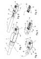
- the connector 1 shown in FIG. 1has a housing which is formed from two thin-walled housing parts 4 and 5, which are coupled to one another via latching lugs. At the rear end of the housing parts a screw 3 is arranged, which serves to clamp a hybrid cable 2 to be connected. From the substantially cuboid housing protrudes on its front side a molded sleeve 6, which is equipped according to a RJ45 connector. In the longitudinal direction parallel openings 9 are provided, which form closely adjacent openings for connecting spring wire sets a socket or a coupling. At the front side, two optical waveguides 7 and 8 emerge from the molded sleeve 6. At the bottom of the mold sleeve, a conventional RJ45 locking device 10 is formed.
- Fig. 2shows a view of Fig. 1, in which the housing parts 4 and 5 have been removed.
- the figureshows that the hybrid cable has 2 electrical conductors 12 and optical fibers 7 and 8, which run parallel.
- the electrical conductors 12lead to electrical connections, which are brought below the pressure block 13 to contacts.
- Fig. 3shows the connector with remote electrical conductors, so that the optical waveguides 7 and 8 can be seen, which are surrounded in the region of the connector of ceramic sleeves 15, 16.
- the hybrid cablecan be firmly fixed on the connector 1 via the clamping ring 14 and the screw 3.
- the mold sleeve 6has on its upper side next to the openings 9 at its rear end two openings 42 and 43, engage in the spring lugs, which are arranged on the encompassed by the mold sleeve 6 connecting block 11. Thus, the mold sleeve is anchored to the connection block.
- Fig. 4shows the connection block 11 with attached board 18.
- the board 18abuts an upper side wall of the cuboid connecting block 11 and also has openings 21 and 22 through which engage the locking lugs of the connecting block 11.
- the connection blockhas two longitudinal bores for receiving the optical fiber ends.
- Fig. 5shows the board 18 in an exempted representation.
- the boardcan be formed in one or more layers.
- Fig. 6the board 18 is shown in plan view with conductors 20 and contact surfaces 19. A corresponding view is shown in FIG. 7 with attached cutting clamps 17.
- the assembly of a connectortakes place in the following manner: the hybrid cable with exposed electrical and optical fiber ends is first passed through the screw 3 and the clamping ring 14. Then, the optical fiber ends are inserted into the provided with the sleeves 15 and 16 holes of the connection block 11 such that the ends of the optical waveguide protrude about 1 cm from the front end of the connector. Now, the board 18 is placed on top of the connection block 11. For example, the board may be latched to the connection block 11, but it may also have previously been glued or welded to the connection block 11.
- the electrical conductors 12are placed on the insulation displacement terminals 17, which are located on the upper side of the circuit board 18.
- Unnecessary wire pairscan be combined by bridges in such a way that a coding arises, which can be recognized by a downstream intelligence for the identification.
- Such an identificationcan also be realized by a chip on the board of the connector, for example by a coding chip or another type of intelligent chip. This can communicate with a downstream intelligence.
- the clamping of the electrical conductor 12 to the insulation displacement terminals 17is carried out by applying a pressure block 13 which is realized as a transverse over the insulation displacement terminals 17 placed plastic block containing recesses for the insulation displacement terminals.
- a pressure block 13which is realized as a transverse over the insulation displacement terminals 17 placed plastic block containing recesses for the insulation displacement terminals.
- the locking lugs of the connecting block 11engage through the openings 21 and 22 of the board 18 in the openings 42 and 43 of the molded sleeve 6 and anchor it thus with the connection block eleventh
- the housing parts 4 and 5are wrapped around the formed connector unit.
- the housing parts 4, 5each contain a rear partial thread on which the screw 3 can be screwed in a known manner, wherein at the same time a fixation and Buchentlasung of the hybrid cable 2 takes place at the connector by the clamping ring 14.
- the inventive use of a board in the connectorleads to a compact design of the connector, in which the electrical contact in the rear end of the connector is possible, the front end in the form of an RJ45 connector can accommodate both the electrical contacts and an optical fiber pair.
- the boardsimultaneously serves the connection the electrical conductor and the formation of the contact surfaces for contacting with spring wire sets a socket or a coupling.
- the housing elementsmay be formed of plastic or be made of metal or metallized, so that a high interference radiation resistance can be achieved.
- Fig. 8shows a coupling for connecting two cables, which are provided with connectors according to FIG.
- the coupling 24has two housing halves 25 and 26, which are provided with recesses 28 and 29, which correspond to a conventional RJ45 socket shape.
- the coupling 24contains electrical spring wire sets 27 for contacting electrical connections of an electrical cable to be connected.
- Fig. 9shows a plug-in coupling in which a housing half has been removed.
- a half-block 32recognizable, containing two guides 30 and 31.
- a board 33below the half block 32 is a board 33, on which a spring wire set 27 is arranged.
- Fig. 10two mutually juxtaposed half-blocks 32 and 33 are shown with arranged below board 33.
- Fig. 11shows the board 33 with only one half block 34. This includes two pins 37 and 38 which engage in opposite holes of the half block 32, not shown, and thereby connect the half-blocks 32 and 34 firmly together.
- the half block 34also shows a corresponding bore 23 into which a pin of the half block 32 can engage.
- the half blocks 32 and 34also have two cursing bores receiving sleeves 35 and 36 into which the optical fiber ends of connectors to be connected according to FIG. 1 can be inserted. This ensures that the optical fibers abut each other precisely on the front side.
- the sleevesmay be plastic, metal or ceramic sleeves, which may also be slotted in order to align the held in ferrules glass or plastic fibers in the correct position.
- Fig. 12shows the sleeves 35 and 36 above the board 33 released. This is shown separately in FIG. 13 and shows two spring wire sets 27 and 39 at the respective end for connection to the contact surface 19 of a connector according to FIG. 6.
- Figures 14 and 15show plan views of the board 33.
- Fig. 14shows the conductor track guide on the board 33 for connecting the solder pads 40 and 41.
- the boardis designed in several layers.
- Fig. 15shows the board 33 with formed spring wire sets 27 and 39th
- the couplingmay include coding means on the board corresponding to those of the connectors.
- the assembly of the plug-in couplingtakes place in that a board according to FIG. 13, together with the two half-blocks 32 and 34, which were previously plugged together and provided with sleeves 35 and 36, are inserted into the housing halves 26 and 25.
- the housing halvesare locked or glued together in a suitable manner. Since the housing halves are each in the form of an RJ45 socket, both conventional RJ45 patch cords and plug connectors according to FIG. 1 can be connected to one another in the socket.
- connection of the individual elements of the connectors and couplingscan also be realized in other ways, for. B. by gluing, welding, screwing or corresponding fasteners.
- composable specified connecting elementssuch.
- the half-blocks 32 and 34can also be made in one piece.
- the plug-in coupling of FIG. 8may have coding elements to achieve an identification of the plug-in coupling.
- the plug-in couplingmay be formed metallized or have metallic housing halves to achieve improved shielding.
- the cables to be connectedare designed in particular as hybrid cables.
- the principle of the inventioncan also be used in separately extending electrical and optical fiber cables, which are brought together only in the connector.
Landscapes
- Physics & Mathematics (AREA)
- General Physics & Mathematics (AREA)
- Optics & Photonics (AREA)
- Connector Housings Or Holding Contact Members (AREA)
- Mechanical Coupling Of Light Guides (AREA)
- Details Of Connecting Devices For Male And Female Coupling (AREA)
- Coupling Device And Connection With Printed Circuit (AREA)
Abstract
Description
Translated fromGermanDie Erfindung betrifft einen Steckverbinder in Form eines RJ45-Anschlusssystems für elektrische und Lichtwellenleiterkabel, insbesondere Hybrid-Datenkabel, nach dem Oberbegriff des Anspruchs 1 sowie eine Steckkupplung in Form eines RJ45-Anschlusssystems nach dem Oberbegriff des Anspruchs 9.The invention relates to a connector in the form of an RJ45 connection system for electrical and optical waveguide cables, in particular hybrid data cables, according to the preamble of claim 1 and a plug-in coupling in the form of an RJ45 connection system according to the preamble of
Steckverbindungen für die heutige Datenübertragungstechnik werden üblicherweise entweder als elektrische Steckverbindungen mit RJ45-Anschlusselementen ausgebildet oder als Lichtwellenleiter, die teilweise ebenfalls RJ45-Anschlussenden aufweisen.Plug-in connections for today's data transmission technology are usually either designed as electrical plug-in connections with RJ45 connection elements or as optical waveguides, which also partially have RJ45 connection ends.
In gemischten Netzen kommen sowohl elektrische Leitungen als auch Lichtwellenleiter zum Einsatz, so dass ein großer Bedarf an mit derartigen Anschlüssen versehenen Kabeln besteht.In mixed networks, both electrical lines and optical fibers are used, so that there is a great need for cables provided with such connections.
Es sind auch Hybridkabel bekannt, die in einem gemeinsamen Kabelmantel sowohl elektrische Leiter als auch Lichtwellenleiter aufnehmen. Üblicherweise werden die Leiterenden an getrennte Steckverbinder geführt.Hybrid cables are also known which receive both electrical conductors and optical fibers in a common cable jacket. Usually, the conductor ends are routed to separate connectors.
Aus der
Aus der
Der Erfindung liegt die Aufgabe zugrunde, eine Steckverbindung in Form eines RJ45-Anschlusssystems anzugeben, die für elektrische und Lichtwellenleiterkabel, insbesondere für Hybridkabel, verwendbar ist, eine hohe Störstrahlfestigkeit ermöglicht und auch für Kabel mit mehreren Lichtwellenleitern geeignet ist.The invention has for its object to provide a connector in the form of an RJ45 connector system, which is for electrical and optical fiber cables, in particular for hybrid cables, usable, allows high Störstrahlfestigkeit and is suitable for cables with multiple optical fibers.
Diese Aufgabe wird durch die in den Ansprüchen 1 und 9 angegebene Erfindung gelöst. Vorteilhafte Weiterbildungen der Erfindung sind in den jeweiligen Unteransprüchen angegeben.This object is solved by the invention specified in
Die Erfindung gemäß Anspruch 1 betrifft einen Steckverbinder in Form eines RJ45-Anschlusssystems für ein Datenkabel mit wenigstens einem Lichtwellenleiter und dazu parallel geführten elektrischen Leitern, mit einer Halterung für ein Ende des Lichtwellenleiter, mit elektrischen Kontakten sowie einem Gehäuse zur Aufnahme der Halterung und der Kontakte.The invention according to claim 1 relates to a connector in the form of an RJ45 connection system for a data cable with at least one optical waveguide and parallel electrical conductors, with a holder for one end of the optical waveguide, with electrical contacts and a housing for receiving the holder and the contacts ,
Mittels solcher Steckverbinder können Kombinationen von elektrischen und Lichtwellenleiterkabeln, insbesondere Hybrid-Datenkabel, an eine Steckkupplung oder eine geräteseitige Buchse angeschlossen werden, wobei durch das Einstecken in die entsprechende Buchse sowohl ein elektrischer als auch ein Lichtwellenleiterkontakt herstellbar ist.By means of such connectors, combinations of electrical and optical fiber cables, in particular hybrid data cables, can be connected to a plug-in coupling or a device-side socket, wherein both an electrical and an optical fiber contact can be produced by plugging into the corresponding socket.
Gemäß der Erfindung weist das Gehäuse des Steckverbinders einen die Halterung bildenden quaderförmigen Verbindungsblock auf, der wenigstens zwei Durchlässe zur Führung von wenigstens zwei Lichtwellenleitern aufweist. Eine Platine enthält Anschlusselemente zum Anschluss der elektrischen Leiter des Datenkabels. Diese ist mit einer Seite des Verbindungsblocks verbindbar und enthält parallel angeordnete Kontaktbahnen, die über Durchbrüche einer den Verbindungsblock und die Platine umgebenden Formhülse zur Kontaktierung der Anschlussdrähte von anzuschließenden elektrischen Verbindern zugänglich sind.According to the invention, the housing of the connector on a support forming cuboid connecting block, which has at least two passages for guiding at least two optical fibers. A circuit board contains connection elements for connecting the electrical conductors of the data cable. This can be connected to one side of the connection block and contains contact paths arranged in parallel, which are accessible via openings of a mold sleeve surrounding the connection block and the circuit board for contacting the connection wires of electrical connectors to be connected.
Ein solcher Steckverbinder ist daher aus einzelnen Elementen zusammengesetzt, die einfach herstellbar und zusammensetzbar sind, aber in ihrer Gesamtausbildung einen hochfesten, präzisen und professionellen Ansprüche erfüllenden Steckverbinder realisiert. Die Durchlässe zur Führung der Lichtwellenleiter erlauben eine präzise Ausrichtung zur möglichst verlustfreien Übertragung von Lichfinrellenenergie. Die elektrischen Kontakte sind gleichzeitig geschützt angeordnet und ermöglichen eine präzise Führung von Kontaktdrähten.Such a connector is therefore composed of individual elements that are easy to manufacture and assemble, but implemented in their overall design a high-strength, precise and professional claims fulfilling connector. The passages for guiding the optical waveguides allow a precise alignment for lossless transmission of Lichfinrellenenergie. The electrical contacts are simultaneously protected and allow precise guidance of contact wires.
Vorzugsweise weist die Platine Schneidklemmen zum Anschluss der elektrischen Leiter des Kabels auf. Die Verbindung und Sicherung der elektrischen Leiter an den Schneidklemmen erfolgt vorzugsweise durch Aufbringen eines Druckblocks quer über die Schneidklemmen, so dass ein schnelles und sicheres Auflegen gewährleistet ist.Preferably, the board on cutting terminals for connecting the electrical conductor of the cable. The connection and securing the electrical conductors to the insulation displacement terminals is preferably carried out by applying a pressure block across the insulation displacement terminals, so that a quick and secure placement is guaranteed.
Vorzugsweise enthält die verwendete Formhülse Ausnehmungen zur mechanischen Verrastung mit Federnasen des Verbindungsblocks. Die Formhülse dient einerseits dem Schutz der elektrischen Anschlüsse, stellt andererseits Führungsdurchbrüche für die Anschlussdrähte einer anzuschließenden Buchse sowie eine Verriegelungsvorrichtung bereit, um den Steckverbinder auf üblichem Wege in der Buchse zu verrasten.Preferably, the mold sleeve used contains recesses for mechanical latching with spring lugs of the connection block. On the one hand, the molded sleeve serves to protect the electrical connections, on the other hand provides guide openings for the connecting wires of a socket to be connected and a locking device in order to lock the plug connector in the usual manner in the socket.
Zur weiteren Verbesserung der Lichtwellenleiterführung können die im Verbindungsblock vorgesehenen Durchlässe Kunststoff-, Metall- oder Keramikhülsen aufweisen.To further improve the optical waveguide guide provided in the connection block passages may have plastic, metal or ceramic sleeves.
Das Gehäuse des Steckverbinders ist vorzugsweise mehrteilig ausgebildet, wobei die einzelnen Gehäuseteile miteinander verrastet werden können. Mittels einer Kabelklemmhülse am hinteren Ende des Gehäuses lässt sich das kombinierte oder Hybridkabel fest mit dem Steckverbinder fixieren.The housing of the connector is preferably designed in several parts, wherein the individual housing parts can be locked together. By means of a cable clamping sleeve at the rear end of the housing, the combined or hybrid cable can be firmly fixed to the connector.
In einer weitergehenden Ausführungsform kann vorgesehen sein, dass die Platine Bestandteil des Führungsblocks ist oder alternativ fest mit dem Führungsblock verrastet, verklebt oder verschweißt ist.In a further embodiment, it can be provided that the board is part of the guide block or alternatively locked firmly with the guide block, glued or welded.
Die Erfindung betrifft auch eine Steckkupplung in Form eines RJ45-Anschlusssystems zur Aufnahme zweier Steckverbinder zur Verbindung zweier Datenkabel, insbesondere Hybridkabel, mit je wenigstens einem Lichtwellenleiter und dazu parallel geführten elektrischen Leitern, mit Halterungen für die Enden der Lichtwellenleiter und mit elektrischen Kontakten sowie einem Gehäuse. Solche Steckkupplungen dienen dazu, zwei mit endseitigen Steckverbindern versehene Kabel miteinander zu koppeln, um z. B. die Kabellänge zu vergrößern.The invention also relates to a plug-in coupling in the form of an RJ45 connection system for receiving two connectors for connecting two data cables, in particular hybrid cables, each with at least one optical waveguide and electrical conductors parallel thereto, with holders for the ends of the optical waveguide and with electrical contacts and a housing , Such plug-in couplings serve to couple two provided with end-side connectors cable with each other to z. B. increase the cable length.
Gemäß der Erfindung weist eine solche Steckkupplung einen quaderförmigen Führungsblock auf, der aus zwei stirnseitig gegeneinander gesetzten und mit zwei fluchtenden Axialbohrungen versehenen Halteblöcken zur Aufnahme und Ausrichtung der zu koppelnden Lichtwellenleitern gebildet ist. An der Außenseite des Führungsblocks ist eine Platine mit zwei darauf jeweils endseitig angeordneten Federdrahtsätzen zur elektrischen Kopplung der zu verbindenden Steckverbinder vorgesehen. Der Führungsblock und die Platine sind miteinander ausgerichtet in einem zweiteiligen Kupplungsgehäuse aufgenommen, wobei die Platine den Führungsblock beidseitig überragt.According to the invention, such a plug-in coupling to a cuboid guide block, which is formed from two frontally set against each other and provided with two aligned axial bores holding blocks for receiving and aligning the optical fibers to be coupled. On the outside of the guide block, a circuit board is provided with two spring wire sets arranged thereon on each end for the electrical coupling of the connectors to be connected. The guide block and the board are aligned with each other in a two-part clutch housing added, the board projects beyond the guide block on both sides.
Eine solche Steckkupplung bildet insbesondere das Gegenstück eines Steckverbinders der in Anspruch 1 angegebenen Art.Such a plug-in coupling forms in particular the counterpart of a connector of the type specified in claim 1.
Vorzugsweise enthält der Führungsblock in seinen Axialbohrungen verankerte Kunststoff-, Metall oder Keramikhülsen, um die Präzision der Führung beidseitig in die Steckkupplung eingesteckter Lichtwellenleiter zu erhöhen.Preferably, the guide block contains anchored in its axial bores plastic, metal or ceramic sleeves to increase the precision of the guide on both sides inserted into the plug-in optical fiber.
Die in der Steckkupplung verwendeten Halbblöcke sind vorzugsweise mittels in Sacklöcher des einen Halbblocks eingreifende Stecknasen des anderen Halbblocks zueinander ausgerichtet und miteinander fixierbar.The half-blocks used in the plug-in coupling are preferably aligned with one another by means of plug-in lugs of the other half-block that engage in blind holes of one half-block and can be fixed to one another.
Die verwendete Platine enthält beidseitig auf der Platine aufgelötete Federdrahtsätze zur Kontaktierung der Leiterbahnen anzuschließender Steckverbinder. Die Federdrahtsätze der beiden Enden der Platine sind auf der Platine geeignet miteinander verschaltet. Anstelle von Leiterbahnen auf der Platine können die Federdrahtsätze auch über Drahtverbindungen miteinander verbunden sein.The board used contains soldered on both sides of the board spring wire sets for contacting the printed conductors to be connected connectors. The spring wire sets of the two ends of the board are suitably interconnected on the board. Instead of printed conductors on the board, the spring wire sets can also be connected to one another via wire connections.
Das erfindungsgemäße Steckverbindersystem, gebildet aus einem Steckverbinder gemäß Anspruch 1 und einer Steckkupplung gemäß Anspruch 9 ist in gemischten Netzen mit großem Vorteil einsetzbar, da insbesondere Hybridkabel durch einen einzigen Steckvorgang sowohl eine elektrische als auch eine Lichtwellenleiterverbindung ermöglichen. Anders als konventionelle Steckverbinder, die entweder nur als Lichtwellenleiterverbinder oder als konventionelle RJ45-Kupferkabelstecker mit aufgesetzten Aufnahmevorrichtungen für Lichtwellenleiterfasem ausgebildet sind, ist der Steckverbinder gemäß der Erfindung kompatibel zu anderen Kupfersystemen, der nur geringe räumliche Ausdehnung hat, eine sichere Verbindung ermöglicht und hohen Anforderungen gerecht wird. Die Steckverbindungen können vor Ort hergestellt werden, da keine besonderen Werkzeuge erforderlich sind. Aufgrund ihrer modularen Ausbildung kann die Steckverbindung auch vor Ort repariert oder ersetzt werden.The connector system according to the invention, formed from a connector according to claim 1 and a plug-in coupling according to
Die Erfindung wird nachstehend anhand zweier Ausführungsbeispiele näher erläutert. Es zeigen:
- Fig. 1
- einen Steckverbinder der erfindungsgemäßen Art in perspektivischer Ansicht,
- Fig. 2
- einen Steckverbinder nach Fig. 1 mit entferntem Gehäuse,
- Fig. 3
- einen Steckverbinder gemäß Fig. 2 mit entferntem Anschlusskabel,
- Fig. 4
- einen Steckverbinder gemäß Fig. 3 ohne Formhülse,
- Fig. 5
- eine Platine zum Einsatz in einen Steckverbinder gemäß Fig. 1,
- Fig. 6
- eine Aufsicht auf eine Platine mit dargestellten Leiterbahnen,
- Fig. 7
- eine Aufsicht auf eine Platine,
- Fig. 8
- eine Steckkupplung,
- Fig. 9
- eine Steckkupplung mit entfernter erster Gehäusehälfte,
- Fig. 10
- eine Steckkupplung ohne Gehäuse,
- Fig. 11
- die Anordnung eines Halbblocks in Bezug auf eine Platine,
- Fig. 12
- eine Platine mit einer Darstellung von Führungshülsen,
- Fig. 13
- eine Platine,
- Fig. 14
- eine erste Aufsicht auf eine Platine, und
- Fig. 15
- eine weitere Aufsicht auf eine Platine.
- Fig. 1
- a connector of the type according to the invention in a perspective view,
- Fig. 2
- a connector according to Fig. 1 with the housing removed,
- Fig. 3
- a connector according to FIG. 2 with the connection cable removed,
- Fig. 4
- a connector according to FIG. 3 without a molded sleeve,
- Fig. 5
- a circuit board for use in a connector according to FIG. 1,
- Fig. 6
- a plan view of a circuit board with illustrated tracks,
- Fig. 7
- a view of a board,
- Fig. 8
- a plug-in coupling,
- Fig. 9
- a plug-in coupling with the first housing half removed,
- Fig. 10
- a plug-in coupling without housing,
- Fig. 11
- the arrangement of a half-block with respect to a board,
- Fig. 12
- a board with a representation of guide sleeves,
- Fig. 13
- a board,
- Fig. 14
- a first view of a board, and
- Fig. 15
- another supervision on a circuit board.
Der in Fig. 1 dargestellte Steckverbinder 1 weist ein Gehäuse auf, das aus zwei dünnwandigen Gehäuseteilen 4 und 5 gebildet ist, die über Rastnasen miteinander gekoppelt sind. Am rückwärtigen Ende der Gehäuseteile ist eine Verschraubung 3 angeordnet, die der Klemmung eines anzuschließenden Hybridkabels 2 dient. Aus dem im Wesentlichen quaderförmigen Gehäuse ragt an seiner Vorderseite eine Formhülse 6 heraus, die entsprechend einem RJ45-Stecker ausgestattet ist. Darin sind in Längsrichtung parallel verlaufende Durchbrüche 9 vorgesehen, die eng nebeneinanderliegende Durchbrüche zum Anschluss von Federdrahtsätzen einer Buchse oder einer Kupplung bilden. An der Stirnseite treten zwei Lichtwellenleiter 7 und 8 aus der Formhülse 6 heraus. An der Unterseite der Formhülse ist eine übliche RJ45-Verriegelungsvorrichtung 10 ausgebildet.The connector 1 shown in FIG. 1 has a housing which is formed from two thin-
Fig. 2 zeigt eine Ansicht von Fig. 1, bei der die Gehäuseteile 4 und 5 entfernt wurden. Die Figur lässt erkennen, dass das Hybridkabel 2 elektrische Leiter 12 sowie Lichtwellenleiter 7 und 8 aufweist, die parallel verlaufen. Die elektrischen Leiter 12 führen auf elektrische Anschlüsse, die unterhalb des Druckblocks 13 an Kontakte herangeführt sind.Fig. 2 shows a view of Fig. 1, in which the
Fig. 3 zeigt den Steckverbinder mit entfernten elektrischen Leitern, so dass die Lichtwellenleiter 7 und 8 erkennbar sind, die im Bereich des Steckverbinders von Keramikhülsen 15, 16 umgeben sind. Das Hybridkabel lässt sich über den Klemmring 14 und die Verschraubung 3 fest am Steckverbinder 1 fixieren.Fig. 3 shows the connector with remote electrical conductors, so that the
Die Formhülse 6 weist auf ihrer Oberseite neben den Durchbrüchen 9 an ihrem rückwärtigen Ende zwei Durchbrüche 42 und 43 auf, in die Federnasen eingreifen, die an dem durch die Formhülse 6 umgriffenen Verbindungsblock 11 angeordnet sind. Damit wird die Formhülse am Verbindungsblock verankert.The
Fig. 4 zeigt den Verbindungsblock 11 mit aufgesetzter Platine 18. Die Platine 18 liegt an einer oberen Seitenwand des quaderförmigen Verbindungsblocks 11 an und weist ebenfalls Durchbrüche 21 und 22 auf, durch die die Rastnasen des Verbindungsblocks 11 hindurchgreifen. Der Verbindungsblock weist zwei Längsbohrungen zur Aufnahme der Lichtwellenleiterenden auf.Fig. 4 shows the
Fig. 5 zeigt die Platine 18 in freigestellter Darstellung. Die Platine kann ein- oder mehrlagig ausgebildet sein.Fig. 5 shows the
In Fig. 6 ist die Platine 18 in Aufsicht mit Leiterbahnen 20 und Kontaktflächen 19 dargestellt. Eine entsprechende Ansicht zeigt Fig. 7 mit angebrachten Schneidklemmen 17.In Fig. 6, the
Die Montage eines Steckverbinders erfolgt in folgender Weise: das Hybridkabel mit freigelegten elektrischen und Lichtwellenleiterenden wird zunächst durch die Verschraubung 3 und dem Klemmring 14 hindurchgeführt. Dann werden die Lichtwellenleiterenden in die mit den Hülsen 15 und 16 versehenen Bohrungen des Verbindungsblocks 11 derart eingeführt, dass die Enden der Lichtwellenleiter ca. 1 cm aus dem Vorderende des Verbindungssteckers herausragen. Nun wird die Platine 18 auf die Oberseite des Verbindungsblocks 11 aufgesetzt. Die Platine kann mit dem Verbindungsblock 11 beispielsweise verrastet werden, sie kann jedoch auch zuvor an dem Verbindungsblock 11 angeklebt oder geschweißt worden sein.The assembly of a connector takes place in the following manner: the hybrid cable with exposed electrical and optical fiber ends is first passed through the
Im folgenden Schritt werden die elektrischen Leiter 12 auf die Schneidklemmen 17 aufgelegt, die sich auf der Oberseite der Platine 18 befinden. Nicht benötigte Adernpaare können durch Brücken so kombiniert werden, dass eine Codierung entsteht, die von einer nachgeschalteten Intelligenz zur Identifikation erkannt werden kann. Eine solche Identifizierung kann auch durch einen Chip auf der Platine des Steckers realisiert werden, beispielsweise durch einen Codierungschip oder eine andere Art eines intelligenten Chips. Dieser kann mit einer nachgeschalteten Intelligenz kommunizieren.In the following step, the
Die Klemmung der elektrischen Leiter 12 mit den Schneidklemmen 17 erfolgt durch Aufbringen eines Druckblocks 13, der als quer über die Schneidklemmen 17 gelegter Kunststoffblock realisiert ist, der Ausnehmungen für die Schneidklemmen enthält. Bei Aufdrücken des Druckblocks 13 werden die elektrischen Leiter in den Schneidklemmen 17 fest verankert.The clamping of the
Im folgenden Schritt wird die Formhülse 6, welche sowohl die Durchbrüche 9 zur Kontaktierung der elektrischen Anschlüsse als auch vorderseitige Öffnungen zur Durchführung der Lichtwellenleiter enthält, auf den Verbindungsblock 11 aufgeschoben. Die Rastnasen des Verbindungsblocks 11 greifen durch die Öffnungen 21 und 22 der Platine 18 in die Öffnungen 42 und 43 der Formhülse 6 ein und verankern diese damit mit dem Verbindungsblock 11.In the following step, the
Schließlich werden die Gehäuseteile 4 und 5 um die gebildete Steckverbindereinheit herumgelegt. Die Gehäuseteile 4, 5 enthalten je ein rückwärtiges Teilgewinde, auf die in bekannter Weise die Verschraubung 3 aufgeschraubt werden kann, wobei durch den Klemmring 14 gleichzeitig eine Fixierung und Zugentlasung des Hybridkabels 2 am Steckverbinder erfolgt.Finally, the
Die erfindungsgemäße Verwendung einer Platine im Steckverbinder führt zu einem kompakten Aufbau des Steckverbinders, bei dem die elektrische Kontaktierung im rückwärtigen Ende des Steckverbinders möglich ist, wobei das Vorderende in Form eines RJ45-Steckers sowohl die elektrischen Kontakte als auch ein Lichtwellenleiterpaar aufnehmen kann. Die Platine dient gleichzeitig dem Anschluss der elektrischen Leiter sowie der Ausbildung der Kontaktflächen zur Kontaktierung mit Federdrahtsätzen einer Buchse oder einer Kupplung.The inventive use of a board in the connector leads to a compact design of the connector, in which the electrical contact in the rear end of the connector is possible, the front end in the form of an RJ45 connector can accommodate both the electrical contacts and an optical fiber pair. The board simultaneously serves the connection the electrical conductor and the formation of the contact surfaces for contacting with spring wire sets a socket or a coupling.
Die Gehäuseelemente können aus Kunststoff ausgebildet sein oder auch aus Metall bzw. metallisiert sein, so dass eine hohe Störstrahlungsfestigkeit erreichbar ist.The housing elements may be formed of plastic or be made of metal or metallized, so that a high interference radiation resistance can be achieved.
Fig. 8 zeigt eine Kupplung zur Verbindung zweier Kabel, welche mit Steckverbindern gemäß Fig. 1 versehen sind. Die Kupplung 24 weist zwei Gehäusehälften 25 und 26 auf, die mit Ausnehmungen 28 und 29 versehen sind, die einer üblichen RJ45-Buchsenform entsprechen.Fig. 8 shows a coupling for connecting two cables, which are provided with connectors according to FIG. The
Die Kupplung 24 enthält elektrische Federdrahtsätze 27 zur Kontaktierung elektrischer Anschlüsse eines anzuschließenden elektrischen Kabels.The
Fig. 9 zeigt eine Steckkupplung, bei der eine Gehäusehälfte entfernt wurde. Es ist ein Halbblock 32 erkennbar, der zwei Führungen 30 und 31 enthält. Unterhalb des Halbblocks 32 befindet sich eine Platine 33, auf der ein Federdrahtsatz 27 angeordnet ist.Fig. 9 shows a plug-in coupling in which a housing half has been removed. There is a half-
In Fig. 10 sind zwei gegeneinander gesetzte Halbblöcke 32 und 33 mit darunter angeordneter Platine 33 dargestellt.In Fig. 10 two mutually juxtaposed half-
Fig. 11 zeigt die Platine 33 mit nur einem Halbblock 34. Dieser enthält zwei Steckstifte 37 und 38, die in gegenüberliegende Bohrungen des nicht dargestellten Halbblocks 32 eingreifen und dadurch die Halbblöcke 32 und 34 miteinander fest verbinden. Der Halbblock 34 zeigt auch eine entsprechende Bohrung 23, in die ein Steckstift des Halbblocks 32 eingreifen kann.Fig. 11 shows the
Die Halbblöcke 32 und 34 weisen auch zwei fluchende Bohrungen auf, die Hülsen 35 und 36 aufnehmen, in die die Lichtleiterenden von anzuschließenden Steckverbindern gemäß Fig. 1 einsteckbar sind. Dadurch ist sichergestellt, dass die Lichtwellenleiter stirnseitig präzise aneinander stoßen. Die Hülsen können Kunststoff-, Metall- oder Keramikhülsen sein, die auch geschlitzt sein können, um die in Ferrulen gehaltene Glas- oder Kunststofffasern lagerichtig ausrichten zu können.The half blocks 32 and 34 also have two cursing
Fig. 12 zeigt die Hülsen 35 und 36 oberhalb der Platine 33 freigestellt. Diese ist in Fig. 13 gesondert dargestellt und zeigt zwei Federdrahtsätze 27 und 39 am jeweiligen Ende zum Anschluss an die Kontaktfläche 19 eines Steckverbinders gemäß Fig. 6.Fig. 12 shows the
Die Figuren 14 und 15 zeigen Aufsichten auf die Platine 33. Fig. 14 zeigt die Leiterbahnführung auf der Platine 33 zur Verbindung der Lötpunkte 40 und 41. Zur Ermöglichung einer gekreuzten Leitungsführung ist die Platine mehrlagig ausgeführt.Figures 14 and 15 show plan views of the
Fig. 15 zeigt die Platine 33 mit ausgebildeten Federdrahtsätzen 27 und 39.Fig. 15 shows the
Auch die Kupplung kann auf der Platine Codierungsmittel entsprechend denen der Steckverbinder enthalten.Also, the coupling may include coding means on the board corresponding to those of the connectors.
Die Montage der Steckkupplung erfolgt dadurch, dass eine Platine gemäß Fig. 13 zusammen mit den beiden Halbblöcken 32 und 34, welche zuvor zusammengesteckt und mit Hülsen 35 und 36 versehen wurden, in die Gehäusehälften 26 und 25 eingesetzt werden. Die Gehäusehälften werden in geeigneter Weise miteinander verrastet oder verklebt. Da die Gehäusehälften jeweils in Form einer RJ45-Buchse ausgebildet sind, können sowohl übliche RJ45-Patchkabel als auch Steckverbinder gemäß Fig. 1 in der Steckbuchse miteinander verbunden werden.The assembly of the plug-in coupling takes place in that a board according to FIG. 13, together with the two half-
Vorstehende Beschreibung zeigt spezielle Ausführungsformen der Erfindung, ohne dass diese darauf beschränkt ist. Die Verbindung der einzelnen Elemente der Steckverbindungen und Kupplungen kann auch auf andere Weise realisiert werden, z. B. durch Kleben, Verschweißen, Verschrauben oder entsprechende Verbindungselemente. Als zusammensetzbar angegebene Verbindungselemente, wie z. B. die Halbblöcke 32 und 34, können auch einstückig hergestellt werden. Nicht nur der Steckverbinder gemäß Fig. 1, sondern auch die Steckkupplung gemäß Fig. 8 kann Codierungselemente aufweisen, um eine Identifizierung der Steckkupplung zu erreichen. Auch die Steckkupplung kann metallisiert ausgebildet sein oder metallische Gehäusehälften aufweisen, um eine verbesserte Abschirmung zu erzielen.The foregoing description shows specific embodiments of the invention without being limited thereto. The connection of the individual elements of the connectors and couplings can also be realized in other ways, for. B. by gluing, welding, screwing or corresponding fasteners. As composable specified connecting elements, such. As the half-
Die anzuschließenden Kabel sind insbesondere als Hybridkabel ausgeführt. Das Prinzip der Erfindung ist jedoch auch bei getrennt verlaufenden elektrischen und Lichtwellenleiterkabeln verwendbar, die erst im Steckverbinder zusammengeführt sind.The cables to be connected are designed in particular as hybrid cables. However, the principle of the invention can also be used in separately extending electrical and optical fiber cables, which are brought together only in the connector.
- 11
- SteckverbinderConnectors
- 22
- Hybridkabelhybrid cable
- 33
- Verschraubungscrew
- 44
- Gehäuseteilhousing part
- 55
- Gehäuseteilhousing part
- 66
- Formhülsemolded sleeve
- 77
- Lichtwellenleiteroptical fiber
- 88th
- Lichtwellenleiteroptical fiber
- 99
- Durchbrüchebreakthroughs
- 1010
- Verriegelungsvorrichtunglocking device
- 1111
- Verbindungslochconnecting hole
- 1212
- elektrische Leiterelectrical conductors
- 1313
- Druckblockpressure block
- 1414
- Klemmringclamping ring
- 1515
- Hülseshell
- 1616
- Hülseshell
- 1717
- Schneidklemmeninsulation displacement terminals
- 1818
- Platinecircuit board
- 1919
- Kontaktflächecontact area
- 2020
- Leiterrahmenleadframe
- 2121
- Durchbruchbreakthrough
- 2222
- Durchbruchbreakthrough
- 2323
- Bohrungdrilling
- 2424
- Kupplungclutch
- 2525
- Gehäusehälftehousing half
- 2626
- Gehäusehälftehousing half
- 2727
- FederdrahtsatzSpring wire set
- 2828
- Ausnehmungrecess
- 2929
- Ausnehmungrecess
- 3030
- Führungguide
- 3131
- Führungguide
- 3232
- Halbblocksemiblock
- 3333
- Platinecircuit board
- 3434
- Halbblocksemiblock
- 3535
- Hülseshell
- 3636
- Hülseshell
- 3737
- Steckstiftmale Pins
- 3838
- Steckstiftmale Pins
- 3939
- FederdrahtsatzSpring wire set
- 4040
- Lötpunkteplumb
- 4141
- Lötpunkteplumb
- 4242
- Durchbruchbreakthrough
- 4343
- Durchbruchbreakthrough
Claims (14)
Translated fromGermandadurch gekennzeichnet,
dass das Gehäuse einen die Halterung bildenden quaderförmigen Verbindungsblock (11) enthält, der wenigstens zwei Durchlässe zur Führung von wenigstens zwei Lichtwellenleitern (7, 8) aufweist, dass eine Platine (18) mit Anschlusselementen (17) zum Anschluss der elektrischen Leiter (12) des Datenkabels vorgesehen ist, dass die Platine (18) mit einer Seite des Verbindungsblocks verbindbar ist, und dass die Platine parallel angeordnete Kontaktbahnen (19) enthält, die über Durchbrüche (9) einer den Verbindungsblock (11) und die Platine (18) umgebenden Formhülse (6) zur Kontaktierung von anzuschließenden elektrischen Verbindern zugänglich sind.Connector in the form of an RJ-45 connection system for a data cable (2), in particular hybrid cable, with at least one optical waveguide (7, 8) and electrical conductors (12) guided in parallel therewith, with a holder (11) for one end of the optical waveguide (7 , 8) and with electrical contacts (18) and a housing (4, 5) for receiving the holder and the contacts,
characterized,
in that the housing contains a block-shaped connecting block (11) forming the holder, which has at least two passages for guiding at least two optical waveguides (7, 8), that a circuit board (18) with connection elements (17) for connecting the electrical conductors (12). the data cable is provided, that the circuit board (18) is connectable to one side of the connection block, and that the board contains parallel arranged contact paths (19), which via openings (9) surrounding the connection block (11) and the circuit board (18) Mold sleeve (6) are accessible for contacting electrical connectors to be connected.
dadurch gekennzeichnet,
dass ein quaderförmiger Führungsblock, gebildet aus zwei stirnseitig gegeneinander gesetzten und mit zwei fluchtenden Axialbohrungen (30, 31) versehenen Halbblöcken (32, 34) vorgesehen ist zur Aufnahme und Ausrichtung der zu koppelnden Lichtwellenleiter, dass an der Außenseite des Führungsblocks eine Platine (33) mit zwei darauf endseitig angeordneten Federdrahtsätzen (27, 39) zur elektrischen Kopplung zu verbindenden Steckverbinder vorgesehen ist, dass der Führungsblock und die Platine (33) miteinander ausgerichtet in einem zweiteiligen Kupplungsgehäuse (25, 26) aufgenommen sind und dass die Platine den Führungsblock in Steckrichtung beidseitig überragt.Plug-in coupling in the form of an RJ-45 connection system for receiving two connectors for connecting two data cables, in particular hybrid cables, each with at least one optical waveguide and parallel electrical conductors, with holders for the ends of the optical waveguide and with electrical contacts and a housing,
characterized,
that a parallelepipedic guide block formed of two end faces against each other set and with two aligned axial bores (30, 31) provided half-blocks (32, 34) is provided for receiving and aligning the to be coupled optical waveguides, that a circuit board on the outer side of the guide block (33) is provided with two arranged on the end spring wire sets (27, 39) for electrical coupling connector to be connected, that the guide block and the board (33) aligned with each other in a two-part coupling housing (25, 26) are added and that the board the guide block in the insertion direction surmounted on both sides.
Priority Applications (4)
| Application Number | Priority Date | Filing Date | Title |
|---|---|---|---|
| DE502005004297TDE502005004297D1 (en) | 2005-11-02 | 2005-11-02 | Plug connector and plug-in coupling in the form of an RJ45 connection system |
| AT05023843TATE397230T1 (en) | 2005-11-02 | 2005-11-02 | CONNECTOR AND PLUG IN THE FORM OF AN RJ45 CONNECTION SYSTEM |
| EP05023843AEP1783521B1 (en) | 2005-11-02 | 2005-11-02 | Connector and RJ-45 connexion system. |
| US11/591,444US7326087B2 (en) | 2005-11-02 | 2006-10-31 | Plug-in connector and coupling in the form of an RJ45 connector jack |
Applications Claiming Priority (1)
| Application Number | Priority Date | Filing Date | Title |
|---|---|---|---|
| EP05023843AEP1783521B1 (en) | 2005-11-02 | 2005-11-02 | Connector and RJ-45 connexion system. |
Publications (2)
| Publication Number | Publication Date |
|---|---|
| EP1783521A1true EP1783521A1 (en) | 2007-05-09 |
| EP1783521B1 EP1783521B1 (en) | 2008-05-28 |
Family
ID=36101511
Family Applications (1)
| Application Number | Title | Priority Date | Filing Date |
|---|---|---|---|
| EP05023843ANot-in-forceEP1783521B1 (en) | 2005-11-02 | 2005-11-02 | Connector and RJ-45 connexion system. |
Country Status (4)
| Country | Link |
|---|---|
| US (1) | US7326087B2 (en) |
| EP (1) | EP1783521B1 (en) |
| AT (1) | ATE397230T1 (en) |
| DE (1) | DE502005004297D1 (en) |
Cited By (2)
| Publication number | Priority date | Publication date | Assignee | Title |
|---|---|---|---|---|
| WO2013026430A1 (en) | 2011-08-23 | 2013-02-28 | Harting Electronics Gmbh & Co. Kg | Connection element for electrical plug connectors |
| CN105024249A (en)* | 2015-05-14 | 2015-11-04 | 东莞市奕联实业有限公司 | Multifunctional data line capable of being connected in series |
Families Citing this family (29)
| Publication number | Priority date | Publication date | Assignee | Title |
|---|---|---|---|---|
| US8061905B2 (en)* | 1999-08-04 | 2011-11-22 | Supertalent Electronics, Inc. | Multi-level cell (MLC) dual personality extended fiber optic flash memory device |
| US7474737B2 (en)* | 2002-10-10 | 2009-01-06 | The Siemon Company | Telecommunications test plugs having tuned near end crosstalk |
| US6962445B2 (en) | 2003-09-08 | 2005-11-08 | Adc Telecommunications, Inc. | Ruggedized fiber optic connection |
| DE112004002592D2 (en)* | 2003-10-28 | 2006-09-21 | Euromicron Werkzeuge Gmbh | Fiber optic connector and single and double clutch for receiving such a connector |
| US7490996B2 (en)* | 2006-08-16 | 2009-02-17 | Sigmund Sommer | Electro-optical plug and receptacle |
| US7572065B2 (en) | 2007-01-24 | 2009-08-11 | Adc Telecommunications, Inc. | Hardened fiber optic connector |
| US7591595B2 (en)* | 2007-01-24 | 2009-09-22 | Adc Telelcommunications, Inc. | Hardened fiber optic adapter |
| US8398314B2 (en)* | 2007-03-30 | 2013-03-19 | Intel Corporation | Optical universal serial bus (USB) |
| US7762726B2 (en)* | 2007-12-11 | 2010-07-27 | Adc Telecommunications, Inc. | Hardened fiber optic connection system |
| DE202008017268U1 (en)* | 2008-05-08 | 2009-04-30 | Krones Ag | Electrical plug connection |
| US7798726B2 (en)* | 2008-08-22 | 2010-09-21 | Hon Hai Precision Ind. Co., Ltd. | Electrical connector with improved signal transmission means |
| US20110200284A1 (en)* | 2009-06-12 | 2011-08-18 | Igor Zhovnirovsky | Fiber Optic Jack with High Interface Mismatch Tolerance |
| US20100316337A1 (en)* | 2009-06-12 | 2010-12-16 | Igor Zhovnirovsky | Fiber Optic Cable Interface |
| EP3584615A1 (en) | 2010-02-04 | 2019-12-25 | ADC Telecommunications, Inc. | Ruggedized fiber optic/electrical connection system |
| CN201698051U (en)* | 2010-02-09 | 2011-01-05 | 富士康(昆山)电脑接插件有限公司 | Cable connector |
| US8467654B2 (en) | 2010-04-05 | 2013-06-18 | Avago Technologies General Ip (Singapore) Pte. Ltd. | Modular connector assembly configured with both optical and electrical connections for providing both optical and electrical communications capabilities, and a system that incorporates the assembly |
| US8794850B2 (en) | 2010-04-05 | 2014-08-05 | Avago Technologies General Ip (Singapore) Pte. Ltd. | Adapter configured with both optical and electrical connections for providing both optical and electrical communications capabilities |
| US8376630B2 (en) | 2010-04-05 | 2013-02-19 | Avago Technologies Fiber Ip (Singapore) Pte. Ltd. | Hybrid 8P8C RJ-45 modular plug configured with both optical and electrical connections for providing both optical and electrical communications capabilities, and a method |
| US7993166B1 (en)* | 2010-06-01 | 2011-08-09 | Hon Hai Precision Ind. Co., Ltd. | Hybrid modular jack |
| US8565562B2 (en) | 2010-09-21 | 2013-10-22 | Intel Corporation | Connector optical lens with alignment features |
| CN102819070B (en) | 2011-06-07 | 2014-10-29 | 富士康(昆山)电脑接插件有限公司 | Cable connector |
| US10958348B2 (en) | 2012-12-29 | 2021-03-23 | Zephyr Photonics Inc. | Method for manufacturing modular multi-function active optical cables |
| WO2014206976A1 (en) | 2013-06-27 | 2014-12-31 | Tyco Electronics Raychem Bvba | Fiber optic cable anchoring device for use with fiber optic connectors and methods of using the same |
| TW201537250A (en)* | 2014-03-26 | 2015-10-01 | Hon Hai Prec Ind Co Ltd | Optical fiber connector |
| US9804342B2 (en) | 2015-03-25 | 2017-10-31 | Foxconn Interconnect Technology Limited | Hybrid connector for both electrical and optical transmission |
| US9891386B2 (en) | 2015-03-25 | 2018-02-13 | Foxconn Interconnect Technology Limited | Hybrid connector for both electrical and optical transmission |
| CN106019491B (en)* | 2015-03-25 | 2019-11-01 | 富士康(昆山)电脑接插件有限公司 | Mix socket connector and mixing pin connector |
| US10113739B2 (en) | 2017-01-06 | 2018-10-30 | Delta Faucet Company | Connector for an electronic faucet |
| TWI695199B (en)* | 2018-09-28 | 2020-06-01 | 光興國際股份有限公司 | Optical to electrical adapter |
Citations (8)
| Publication number | Priority date | Publication date | Assignee | Title |
|---|---|---|---|---|
| US6364535B1 (en)* | 2000-08-10 | 2002-04-02 | Adc | Upgradeable media wall converter and housing |
| EP1199587A1 (en) | 2000-10-18 | 2002-04-24 | Lucent Technologies Inc. | Optical/electrical plug connector |
| EP1211537A2 (en)* | 2000-10-18 | 2002-06-05 | Lucent Technologies Inc. | Optical/electrical jack receptacle |
| EP1258759A2 (en)* | 2001-05-16 | 2002-11-20 | Fci | Fiber optic adapter |
| WO2003016972A1 (en)* | 2001-08-15 | 2003-02-27 | Stratos Lightwave, Inc. | Communications transceiver with internal emi shield associated methods |
| DE20202835U1 (en)* | 2002-02-22 | 2003-03-27 | CCS Technology, Inc., Wilmington, Del. | Optical cable jack-plug connector has connector plugs at ends of optical cables inserted in opposing ends of socket sleeve providing both electrical and optical conductor connections |
| DE20317751U1 (en) | 2003-10-28 | 2005-03-10 | Euromicron Werkzeuge Gmbh | Process to manufacture a two-part connector for fiber optic cable using modified prior art connector housing |
| US20050118880A1 (en)* | 2002-05-02 | 2005-06-02 | Martin Reichle | Hybrid plug connector |
Family Cites Families (7)
| Publication number | Priority date | Publication date | Assignee | Title |
|---|---|---|---|---|
| US5896480A (en)* | 1996-10-22 | 1999-04-20 | Stewart Connector Systems, Inc. | Optical interconnection system |
| US6718099B2 (en)* | 1998-06-11 | 2004-04-06 | James T. Chivers | Pin insertion tool and method for measuring endface surface topography of multi-fiber fiberoptic connectors |
| US6802653B2 (en)* | 2000-11-14 | 2004-10-12 | National Semiconductor Corporation | Method and apparatus for adapting a miniature form-factor connector to a standard format fiber optic connector plug |
| US6692159B2 (en)* | 2001-04-14 | 2004-02-17 | E20 Communications, Inc. | De-latching mechanisms for fiber optic modules |
| US7194183B2 (en)* | 2003-09-19 | 2007-03-20 | Enterasys Networks, Inc. | Modular receptacle assembly and interface with integral optical indication |
| US7234879B2 (en)* | 2004-09-17 | 2007-06-26 | Finisar Corporation | Optical connector |
| US7217043B2 (en)* | 2004-10-06 | 2007-05-15 | Infineon Technologies Fiber Optics Gmbh | Optoelectronic transceiver |
- 2005
- 2005-11-02EPEP05023843Apatent/EP1783521B1/ennot_activeNot-in-force
- 2005-11-02ATAT05023843Tpatent/ATE397230T1/ennot_activeIP Right Cessation
- 2005-11-02DEDE502005004297Tpatent/DE502005004297D1/enactiveActive
- 2006
- 2006-10-31USUS11/591,444patent/US7326087B2/ennot_activeExpired - Fee Related
Patent Citations (8)
| Publication number | Priority date | Publication date | Assignee | Title |
|---|---|---|---|---|
| US6364535B1 (en)* | 2000-08-10 | 2002-04-02 | Adc | Upgradeable media wall converter and housing |
| EP1199587A1 (en) | 2000-10-18 | 2002-04-24 | Lucent Technologies Inc. | Optical/electrical plug connector |
| EP1211537A2 (en)* | 2000-10-18 | 2002-06-05 | Lucent Technologies Inc. | Optical/electrical jack receptacle |
| EP1258759A2 (en)* | 2001-05-16 | 2002-11-20 | Fci | Fiber optic adapter |
| WO2003016972A1 (en)* | 2001-08-15 | 2003-02-27 | Stratos Lightwave, Inc. | Communications transceiver with internal emi shield associated methods |
| DE20202835U1 (en)* | 2002-02-22 | 2003-03-27 | CCS Technology, Inc., Wilmington, Del. | Optical cable jack-plug connector has connector plugs at ends of optical cables inserted in opposing ends of socket sleeve providing both electrical and optical conductor connections |
| US20050118880A1 (en)* | 2002-05-02 | 2005-06-02 | Martin Reichle | Hybrid plug connector |
| DE20317751U1 (en) | 2003-10-28 | 2005-03-10 | Euromicron Werkzeuge Gmbh | Process to manufacture a two-part connector for fiber optic cable using modified prior art connector housing |
Cited By (2)
| Publication number | Priority date | Publication date | Assignee | Title |
|---|---|---|---|---|
| WO2013026430A1 (en) | 2011-08-23 | 2013-02-28 | Harting Electronics Gmbh & Co. Kg | Connection element for electrical plug connectors |
| CN105024249A (en)* | 2015-05-14 | 2015-11-04 | 东莞市奕联实业有限公司 | Multifunctional data line capable of being connected in series |
Also Published As
| Publication number | Publication date |
|---|---|
| ATE397230T1 (en) | 2008-06-15 |
| DE502005004297D1 (en) | 2008-07-10 |
| EP1783521B1 (en) | 2008-05-28 |
| US20070105452A1 (en) | 2007-05-10 |
| US7326087B2 (en) | 2008-02-05 |
Similar Documents
| Publication | Publication Date | Title |
|---|---|---|
| EP1783521B1 (en) | Connector and RJ-45 connexion system. | |
| EP2417673B1 (en) | Electrical plug-in connector | |
| DE60100091T2 (en) | Optical and electrical connector | |
| DE10203162B4 (en) | Interconnects | |
| EP0516930B1 (en) | Apparatus for connecting conductors | |
| DE19810561A1 (en) | Hybrid data plug | |
| EP2466697B1 (en) | Data cable connection module and method for producing same on a cable | |
| EP2366212B1 (en) | Electric multiple distributor | |
| DE202004001202U1 (en) | Modular socket connector system | |
| EP0061772B1 (en) | Electro-optical plug-connector module | |
| DE102008034261A1 (en) | Plug connector i.e. RJ45-plug connector, for electrical data transmission cable, has springy latching element arranged at rear edge of block, where radio frequency identification transponder is accommodated in front side drilling in block | |
| DE10003420A1 (en) | Optical waveguide for connection with optical plug, has plug frame connected to an optical connector | |
| WO2002023235A2 (en) | Optical waveguide socket, optical waveguide plug, and optical waveguide socket assembly | |
| DE3940652C2 (en) | Electrical connector | |
| DE10323616A1 (en) | Rapid connection plug or socket connector in clamping jaws technology has contact partner with region in form of clamping jaws for accommodating stripped end of line of especially multi-strand cable | |
| CH674281A5 (en) | ||
| DE19733174A1 (en) | Optical conductor plug connector | |
| DE10258725B4 (en) | Connector for information technology connections | |
| EP0905830B1 (en) | Connection device having plug-in connections | |
| DE19531633A1 (en) | Optical data communication system | |
| DE102011089025A1 (en) | USB port | |
| EP0923171B1 (en) | Socket for RJ45 plug | |
| DE10360105A1 (en) | Connection module for telecommunication and data technology | |
| DE60200782T2 (en) | Comb and method for branching for an existing line | |
| DE19926677C2 (en) | Method and device for coupling optical fibers |
Legal Events
| Date | Code | Title | Description |
|---|---|---|---|
| PUAI | Public reference made under article 153(3) epc to a published international application that has entered the european phase | Free format text:ORIGINAL CODE: 0009012 | |
| 17P | Request for examination filed | Effective date:20060704 | |
| AK | Designated contracting states | Kind code of ref document:A1 Designated state(s):AT BE BG CH CY CZ DE DK EE ES FI FR GB GR HU IE IS IT LI LT LU LV MC NL PL PT RO SE SI SK TR | |
| AX | Request for extension of the european patent | Extension state:AL BA HR MK YU | |
| GRAP | Despatch of communication of intention to grant a patent | Free format text:ORIGINAL CODE: EPIDOSNIGR1 | |
| GRAS | Grant fee paid | Free format text:ORIGINAL CODE: EPIDOSNIGR3 | |
| AKX | Designation fees paid | Designated state(s):AT BE BG CH CY CZ DE DK EE ES FI FR GB GR HU IE IS IT LI LT LU LV MC NL PL PT RO SE SI SK TR | |
| GRAA | (expected) grant | Free format text:ORIGINAL CODE: 0009210 | |
| AK | Designated contracting states | Kind code of ref document:B1 Designated state(s):AT BE BG CH CY CZ DE DK EE ES FI FR GB GR HU IE IS IT LI LT LU LV MC NL PL PT RO SE SI SK TR | |
| REG | Reference to a national code | Ref country code:GB Ref legal event code:FG4D Free format text:NOT ENGLISH | |
| REG | Reference to a national code | Ref country code:CH Ref legal event code:EP | |
| REF | Corresponds to: | Ref document number:502005004297 Country of ref document:DE Date of ref document:20080710 Kind code of ref document:P | |
| REG | Reference to a national code | Ref country code:IE Ref legal event code:FG4D Free format text:LANGUAGE OF EP DOCUMENT: GERMAN | |
| PG25 | Lapsed in a contracting state [announced via postgrant information from national office to epo] | Ref country code:SI Free format text:LAPSE BECAUSE OF FAILURE TO SUBMIT A TRANSLATION OF THE DESCRIPTION OR TO PAY THE FEE WITHIN THE PRESCRIBED TIME-LIMIT Effective date:20080528 | |
| PG25 | Lapsed in a contracting state [announced via postgrant information from national office to epo] | Ref country code:ES Free format text:LAPSE BECAUSE OF FAILURE TO SUBMIT A TRANSLATION OF THE DESCRIPTION OR TO PAY THE FEE WITHIN THE PRESCRIBED TIME-LIMIT Effective date:20080908 Ref country code:FI Free format text:LAPSE BECAUSE OF FAILURE TO SUBMIT A TRANSLATION OF THE DESCRIPTION OR TO PAY THE FEE WITHIN THE PRESCRIBED TIME-LIMIT Effective date:20080528 | |
| PG25 | Lapsed in a contracting state [announced via postgrant information from national office to epo] | Ref country code:NL Free format text:LAPSE BECAUSE OF FAILURE TO SUBMIT A TRANSLATION OF THE DESCRIPTION OR TO PAY THE FEE WITHIN THE PRESCRIBED TIME-LIMIT Effective date:20080528 Ref country code:LV Free format text:LAPSE BECAUSE OF FAILURE TO SUBMIT A TRANSLATION OF THE DESCRIPTION OR TO PAY THE FEE WITHIN THE PRESCRIBED TIME-LIMIT Effective date:20080528 | |
| NLV1 | Nl: lapsed or annulled due to failure to fulfill the requirements of art. 29p and 29m of the patents act | ||
| PG25 | Lapsed in a contracting state [announced via postgrant information from national office to epo] | Ref country code:IS Free format text:LAPSE BECAUSE OF FAILURE TO SUBMIT A TRANSLATION OF THE DESCRIPTION OR TO PAY THE FEE WITHIN THE PRESCRIBED TIME-LIMIT Effective date:20080928 | |
| REG | Reference to a national code | Ref country code:IE Ref legal event code:FD4D | |
| PG25 | Lapsed in a contracting state [announced via postgrant information from national office to epo] | Ref country code:DK Free format text:LAPSE BECAUSE OF FAILURE TO SUBMIT A TRANSLATION OF THE DESCRIPTION OR TO PAY THE FEE WITHIN THE PRESCRIBED TIME-LIMIT Effective date:20080528 Ref country code:IE Free format text:LAPSE BECAUSE OF FAILURE TO SUBMIT A TRANSLATION OF THE DESCRIPTION OR TO PAY THE FEE WITHIN THE PRESCRIBED TIME-LIMIT Effective date:20080528 Ref country code:PT Free format text:LAPSE BECAUSE OF FAILURE TO SUBMIT A TRANSLATION OF THE DESCRIPTION OR TO PAY THE FEE WITHIN THE PRESCRIBED TIME-LIMIT Effective date:20081028 Ref country code:SE Free format text:LAPSE BECAUSE OF FAILURE TO SUBMIT A TRANSLATION OF THE DESCRIPTION OR TO PAY THE FEE WITHIN THE PRESCRIBED TIME-LIMIT Effective date:20080828 Ref country code:LT Free format text:LAPSE BECAUSE OF FAILURE TO SUBMIT A TRANSLATION OF THE DESCRIPTION OR TO PAY THE FEE WITHIN THE PRESCRIBED TIME-LIMIT Effective date:20080528 Ref country code:CZ Free format text:LAPSE BECAUSE OF FAILURE TO SUBMIT A TRANSLATION OF THE DESCRIPTION OR TO PAY THE FEE WITHIN THE PRESCRIBED TIME-LIMIT Effective date:20080528 | |
| PG25 | Lapsed in a contracting state [announced via postgrant information from national office to epo] | Ref country code:RO Free format text:LAPSE BECAUSE OF FAILURE TO SUBMIT A TRANSLATION OF THE DESCRIPTION OR TO PAY THE FEE WITHIN THE PRESCRIBED TIME-LIMIT Effective date:20080528 Ref country code:SK Free format text:LAPSE BECAUSE OF FAILURE TO SUBMIT A TRANSLATION OF THE DESCRIPTION OR TO PAY THE FEE WITHIN THE PRESCRIBED TIME-LIMIT Effective date:20080528 | |
| PLBE | No opposition filed within time limit | Free format text:ORIGINAL CODE: 0009261 | |
| STAA | Information on the status of an ep patent application or granted ep patent | Free format text:STATUS: NO OPPOSITION FILED WITHIN TIME LIMIT | |
| PG25 | Lapsed in a contracting state [announced via postgrant information from national office to epo] | Ref country code:BG Free format text:LAPSE BECAUSE OF FAILURE TO SUBMIT A TRANSLATION OF THE DESCRIPTION OR TO PAY THE FEE WITHIN THE PRESCRIBED TIME-LIMIT Effective date:20080828 Ref country code:EE Free format text:LAPSE BECAUSE OF FAILURE TO SUBMIT A TRANSLATION OF THE DESCRIPTION OR TO PAY THE FEE WITHIN THE PRESCRIBED TIME-LIMIT Effective date:20080528 | |
| 26N | No opposition filed | Effective date:20090303 | |
| BERE | Be: lapsed | Owner name:TKM TELEKOMMUNIKATION UND ELEKTRONIK G.M.B.H. Effective date:20081130 | |
| PG25 | Lapsed in a contracting state [announced via postgrant information from national office to epo] | Ref country code:MC Free format text:LAPSE BECAUSE OF NON-PAYMENT OF DUE FEES Effective date:20081130 | |
| PG25 | Lapsed in a contracting state [announced via postgrant information from national office to epo] | Ref country code:IT Free format text:LAPSE BECAUSE OF FAILURE TO SUBMIT A TRANSLATION OF THE DESCRIPTION OR TO PAY THE FEE WITHIN THE PRESCRIBED TIME-LIMIT Effective date:20080528 | |
| PG25 | Lapsed in a contracting state [announced via postgrant information from national office to epo] | Ref country code:BE Free format text:LAPSE BECAUSE OF NON-PAYMENT OF DUE FEES Effective date:20081130 | |
| PG25 | Lapsed in a contracting state [announced via postgrant information from national office to epo] | Ref country code:AT Free format text:LAPSE BECAUSE OF NON-PAYMENT OF DUE FEES Effective date:20081102 | |
| REG | Reference to a national code | Ref country code:FR Ref legal event code:TP | |
| REG | Reference to a national code | Ref country code:GB Ref legal event code:732E Free format text:REGISTERED BETWEEN 20100401 AND 20100407 | |
| PG25 | Lapsed in a contracting state [announced via postgrant information from national office to epo] | Ref country code:PL Free format text:LAPSE BECAUSE OF FAILURE TO SUBMIT A TRANSLATION OF THE DESCRIPTION OR TO PAY THE FEE WITHIN THE PRESCRIBED TIME-LIMIT Effective date:20080528 | |
| REG | Reference to a national code | Ref country code:CH Ref legal event code:PL | |
| PG25 | Lapsed in a contracting state [announced via postgrant information from national office to epo] | Ref country code:LU Free format text:LAPSE BECAUSE OF NON-PAYMENT OF DUE FEES Effective date:20081102 Ref country code:HU Free format text:LAPSE BECAUSE OF FAILURE TO SUBMIT A TRANSLATION OF THE DESCRIPTION OR TO PAY THE FEE WITHIN THE PRESCRIBED TIME-LIMIT Effective date:20081129 Ref country code:CY Free format text:LAPSE BECAUSE OF FAILURE TO SUBMIT A TRANSLATION OF THE DESCRIPTION OR TO PAY THE FEE WITHIN THE PRESCRIBED TIME-LIMIT Effective date:20080528 | |
| PG25 | Lapsed in a contracting state [announced via postgrant information from national office to epo] | Ref country code:TR Free format text:LAPSE BECAUSE OF FAILURE TO SUBMIT A TRANSLATION OF THE DESCRIPTION OR TO PAY THE FEE WITHIN THE PRESCRIBED TIME-LIMIT Effective date:20080528 | |
| PG25 | Lapsed in a contracting state [announced via postgrant information from national office to epo] | Ref country code:CH Free format text:LAPSE BECAUSE OF NON-PAYMENT OF DUE FEES Effective date:20091130 Ref country code:LI Free format text:LAPSE BECAUSE OF NON-PAYMENT OF DUE FEES Effective date:20091130 Ref country code:GR Free format text:LAPSE BECAUSE OF FAILURE TO SUBMIT A TRANSLATION OF THE DESCRIPTION OR TO PAY THE FEE WITHIN THE PRESCRIBED TIME-LIMIT Effective date:20080829 | |
| REG | Reference to a national code | Ref country code:FR Ref legal event code:PLFP Year of fee payment:11 | |
| REG | Reference to a national code | Ref country code:FR Ref legal event code:PLFP Year of fee payment:12 | |
| REG | Reference to a national code | Ref country code:FR Ref legal event code:PLFP Year of fee payment:13 | |
| REG | Reference to a national code | Ref country code:DE Ref legal event code:R082 Ref document number:502005004297 Country of ref document:DE Representative=s name:ADVOTEC. PATENT- UND RECHTSANWAELTE, DE | |
| PGFP | Annual fee paid to national office [announced via postgrant information from national office to epo] | Ref country code:FR Payment date:20181127 Year of fee payment:14 Ref country code:GB Payment date:20181126 Year of fee payment:14 | |
| PGFP | Annual fee paid to national office [announced via postgrant information from national office to epo] | Ref country code:DE Payment date:20190122 Year of fee payment:14 | |
| REG | Reference to a national code | Ref country code:DE Ref legal event code:R119 Ref document number:502005004297 Country of ref document:DE | |
| GBPC | Gb: european patent ceased through non-payment of renewal fee | Effective date:20191102 | |
| PG25 | Lapsed in a contracting state [announced via postgrant information from national office to epo] | Ref country code:FR Free format text:LAPSE BECAUSE OF NON-PAYMENT OF DUE FEES Effective date:20191130 Ref country code:DE Free format text:LAPSE BECAUSE OF NON-PAYMENT OF DUE FEES Effective date:20200603 Ref country code:GB Free format text:LAPSE BECAUSE OF NON-PAYMENT OF DUE FEES Effective date:20191102 |