EP1782854A2 - Apparatus and method for rapid auto-injection of medication - Google Patents
Apparatus and method for rapid auto-injection of medicationDownload PDFInfo
- Publication number
- EP1782854A2 EP1782854A2EP07003508AEP07003508AEP1782854A2EP 1782854 A2EP1782854 A2EP 1782854A2EP 07003508 AEP07003508 AEP 07003508AEP 07003508 AEP07003508 AEP 07003508AEP 1782854 A2EP1782854 A2EP 1782854A2
- Authority
- EP
- European Patent Office
- Prior art keywords
- needle
- housing
- syringe
- injection
- forward end
- Prior art date
- Legal status (The legal status is an assumption and is not a legal conclusion. Google has not performed a legal analysis and makes no representation as to the accuracy of the status listed.)
- Granted
Links
- 238000002347injectionMethods0.000titleclaimsabstractdescription97
- 239000007924injectionSubstances0.000titleclaimsabstractdescription97
- 239000003814drugSubstances0.000titleclaimsabstractdescription91
- 229940079593drugDrugs0.000titleclaimsabstractdescription85
- 238000000034methodMethods0.000titledescription10
- 230000033001locomotionEffects0.000claimsdescription25
- 229940090047auto-injectorDrugs0.000claimsdescription24
- 230000000977initiatory effectEffects0.000claims1
- 229940090044injectionDrugs0.000description84
- UCTWMZQNUQWSLP-VIFPVBQESA-N(R)-adrenalineChemical compoundCNC[C@H](O)C1=CC=C(O)C(O)=C1UCTWMZQNUQWSLP-VIFPVBQESA-N0.000description17
- 230000002093peripheral effectEffects0.000description16
- 229930182837(R)-adrenalineNatural products0.000description14
- 229960005139epinephrineDrugs0.000description14
- 208000003455anaphylaxisDiseases0.000description11
- 239000000463materialSubstances0.000description11
- 206010002198Anaphylactic reactionDiseases0.000description10
- 230000006835compressionEffects0.000description9
- 238000007906compressionMethods0.000description9
- 230000000694effectsEffects0.000description9
- 238000003825pressingMethods0.000description8
- 238000003860storageMethods0.000description8
- 230000036783anaphylactic responseEffects0.000description7
- 235000013305foodNutrition0.000description6
- 238000002483medicationMethods0.000description6
- -1vaccinesSubstances0.000description6
- 206010020751HypersensitivityDiseases0.000description5
- 238000004891communicationMethods0.000description5
- NOESYZHRGYRDHS-UHFFFAOYSA-NinsulinChemical compoundN1C(=O)C(NC(=O)C(CCC(N)=O)NC(=O)C(CCC(O)=O)NC(=O)C(C(C)C)NC(=O)C(NC(=O)CN)C(C)CC)CSSCC(C(NC(CO)C(=O)NC(CC(C)C)C(=O)NC(CC=2C=CC(O)=CC=2)C(=O)NC(CCC(N)=O)C(=O)NC(CC(C)C)C(=O)NC(CCC(O)=O)C(=O)NC(CC(N)=O)C(=O)NC(CC=2C=CC(O)=CC=2)C(=O)NC(CSSCC(NC(=O)C(C(C)C)NC(=O)C(CC(C)C)NC(=O)C(CC=2C=CC(O)=CC=2)NC(=O)C(CC(C)C)NC(=O)C(C)NC(=O)C(CCC(O)=O)NC(=O)C(C(C)C)NC(=O)C(CC(C)C)NC(=O)C(CC=2NC=NC=2)NC(=O)C(CO)NC(=O)CNC2=O)C(=O)NCC(=O)NC(CCC(O)=O)C(=O)NC(CCCNC(N)=N)C(=O)NCC(=O)NC(CC=3C=CC=CC=3)C(=O)NC(CC=3C=CC=CC=3)C(=O)NC(CC=3C=CC(O)=CC=3)C(=O)NC(C(C)O)C(=O)N3C(CCC3)C(=O)NC(CCCCN)C(=O)NC(C)C(O)=O)C(=O)NC(CC(N)=O)C(O)=O)=O)NC(=O)C(C(C)CC)NC(=O)C(CO)NC(=O)C(C(C)O)NC(=O)C1CSSCC2NC(=O)C(CC(C)C)NC(=O)C(NC(=O)C(CCC(N)=O)NC(=O)C(CC(N)=O)NC(=O)C(NC(=O)C(N)CC=1C=CC=CC=1)C(C)C)CC1=CN=CN1NOESYZHRGYRDHS-UHFFFAOYSA-N0.000description4
- 239000012528membraneSubstances0.000description4
- BQJCRHHNABKAKU-KBQPJGBKSA-NmorphineChemical compoundO([C@H]1[C@H](C=C[C@H]23)O)C4=C5[C@@]12CCN(C)[C@@H]3CC5=CC=C4OBQJCRHHNABKAKU-KBQPJGBKSA-N0.000description4
- 230000000717retained effectEffects0.000description4
- 230000007815allergyEffects0.000description3
- 239000003146anticoagulant agentSubstances0.000description3
- 229940127219anticoagulant drugDrugs0.000description3
- 238000013459approachMethods0.000description3
- 230000000712assemblyEffects0.000description3
- 238000000429assemblyMethods0.000description3
- 229940015979epipenDrugs0.000description3
- 230000001965increasing effectEffects0.000description3
- 238000002372labellingMethods0.000description3
- 230000013011matingEffects0.000description3
- 230000007246mechanismEffects0.000description3
- 230000035515penetrationEffects0.000description3
- 230000004044responseEffects0.000description3
- 229930003347AtropineNatural products0.000description2
- 102000007644Colony-Stimulating FactorsHuman genes0.000description2
- 108010071942Colony-Stimulating FactorsProteins0.000description2
- 102000003951ErythropoietinHuman genes0.000description2
- 108090000394ErythropoietinProteins0.000description2
- 108010051696Growth HormoneProteins0.000description2
- 102000018997Growth HormoneHuman genes0.000description2
- RKUNBYITZUJHSG-UHFFFAOYSA-NHyosciamin-hydrochloridNatural productsCN1C(C2)CCC1CC2OC(=O)C(CO)C1=CC=CC=C1RKUNBYITZUJHSG-UHFFFAOYSA-N0.000description2
- 208000006877Insect Bites and StingsDiseases0.000description2
- 102000004877InsulinHuman genes0.000description2
- 108090001061InsulinProteins0.000description2
- 102000002852VasopressinsHuman genes0.000description2
- 108010004977VasopressinsProteins0.000description2
- 239000000853adhesiveSubstances0.000description2
- 230000001070adhesive effectEffects0.000description2
- UCTWMZQNUQWSLP-UHFFFAOYSA-NadrenalineChemical compoundCNCC(O)C1=CC=C(O)C(O)=C1UCTWMZQNUQWSLP-UHFFFAOYSA-N0.000description2
- 239000013566allergenSubstances0.000description2
- 230000002009allergenic effectEffects0.000description2
- 208000026935allergic diseaseDiseases0.000description2
- 229940035676analgesicsDrugs0.000description2
- 239000000730antalgic agentSubstances0.000description2
- 230000003288anthiarrhythmic effectEffects0.000description2
- 239000003242anti bacterial agentSubstances0.000description2
- 230000001078anti-cholinergic effectEffects0.000description2
- 230000002460anti-migrenic effectEffects0.000description2
- 230000001062anti-nauseaEffects0.000description2
- 230000000573anti-seizure effectEffects0.000description2
- 230000001147anti-toxic effectEffects0.000description2
- 230000001362anti-vertigoEffects0.000description2
- 239000003416antiarrhythmic agentSubstances0.000description2
- 229940088710antibiotic agentDrugs0.000description2
- 239000000164antipsychotic agentSubstances0.000description2
- 239000002249anxiolytic agentSubstances0.000description2
- KBZOIRJILGZLEJ-LGYYRGKSSA-NargipressinChemical compoundC([C@H]1C(=O)N[C@@H](CCC(N)=O)C(=O)N[C@@H](CC(N)=O)C(=O)N[C@@H](CSSC[C@@H](C(N[C@@H](CC=2C=CC(O)=CC=2)C(=O)N1)=O)N)C(=O)N1[C@@H](CCC1)C(=O)N[C@@H](CCCN=C(N)N)C(=O)NCC(N)=O)C1=CC=CC=C1KBZOIRJILGZLEJ-LGYYRGKSSA-N0.000description2
- RKUNBYITZUJHSG-SPUOUPEWSA-NatropineChemical compoundO([C@H]1C[C@H]2CC[C@@H](C1)N2C)C(=O)C(CO)C1=CC=CC=C1RKUNBYITZUJHSG-SPUOUPEWSA-N0.000description2
- 229960000396atropineDrugs0.000description2
- 238000006243chemical reactionMethods0.000description2
- 230000000718cholinopositive effectEffects0.000description2
- 229940124558contraceptive agentDrugs0.000description2
- 239000003433contraceptive agentSubstances0.000description2
- 239000003246corticosteroidSubstances0.000description2
- 229960001334corticosteroidsDrugs0.000description2
- 230000034994deathEffects0.000description2
- 231100000517deathToxicity0.000description2
- 239000002934diureticSubstances0.000description2
- 229940030606diureticsDrugs0.000description2
- 229940105423erythropoietinDrugs0.000description2
- 230000004927fusionEffects0.000description2
- 230000002496gastric effectEffects0.000description2
- 239000011521glassSubstances0.000description2
- 239000000122growth hormoneSubstances0.000description2
- LNEPOXFFQSENCJ-UHFFFAOYSA-NhaloperidolChemical compoundC1CC(O)(C=2C=CC(Cl)=CC=2)CCN1CCCC(=O)C1=CC=C(F)C=C1LNEPOXFFQSENCJ-UHFFFAOYSA-N0.000description2
- 230000036512infertilityEffects0.000description2
- 239000004615ingredientSubstances0.000description2
- 239000003112inhibitorSubstances0.000description2
- 229940125396insulinDrugs0.000description2
- 238000010255intramuscular injectionMethods0.000description2
- 239000007927intramuscular injectionSubstances0.000description2
- 231100000518lethalToxicity0.000description2
- 230000001665lethal effectEffects0.000description2
- 230000000670limiting effectEffects0.000description2
- 239000007788liquidSubstances0.000description2
- 239000002184metalSubstances0.000description2
- 229960005181morphineDrugs0.000description2
- 201000006417multiple sclerosisDiseases0.000description2
- 239000004033plasticSubstances0.000description2
- 229920003023plasticPolymers0.000description2
- 229920000139polyethylene terephthalatePolymers0.000description2
- 239000005020polyethylene terephthalateSubstances0.000description2
- 229920000642polymerPolymers0.000description2
- OXCMYAYHXIHQOA-UHFFFAOYSA-Npotassium;[2-butyl-5-chloro-3-[[4-[2-(1,2,4-triaza-3-azanidacyclopenta-1,4-dien-5-yl)phenyl]phenyl]methyl]imidazol-4-yl]methanolChemical compound[K+].CCCCC1=NC(Cl)=C(CO)N1CC1=CC=C(C=2C(=CC=CC=2)C2=N[N-]N=N2)C=C1OXCMYAYHXIHQOA-UHFFFAOYSA-N0.000description2
- 239000002244precipitateSubstances0.000description2
- 230000001681protective effectEffects0.000description2
- 230000002829reductive effectEffects0.000description2
- 238000007789sealingMethods0.000description2
- 239000000021stimulantSubstances0.000description2
- 238000010254subcutaneous injectionMethods0.000description2
- 239000007929subcutaneous injectionSubstances0.000description2
- 238000012549trainingMethods0.000description2
- 210000000689upper legAnatomy0.000description2
- 229960005486vaccineDrugs0.000description2
- 229960003726vasopressinDrugs0.000description2
- 229940088594vitaminDrugs0.000description2
- 239000011782vitaminSubstances0.000description2
- 229930003231vitaminNatural products0.000description2
- 235000013343vitaminNutrition0.000description2
- VHRSUDSXCMQTMA-PJHHCJLFSA-N6alpha-methylprednisoloneChemical compoundC([C@@]12C)=CC(=O)C=C1[C@@H](C)C[C@@H]1[C@@H]2[C@@H](O)C[C@]2(C)[C@@](O)(C(=O)CO)CC[C@H]21VHRSUDSXCMQTMA-PJHHCJLFSA-N0.000description1
- RZVAJINKPMORJF-UHFFFAOYSA-NAcetaminophenChemical compoundCC(=O)NC1=CC=C(O)C=C1RZVAJINKPMORJF-UHFFFAOYSA-N0.000description1
- 241001553178Arachis glabrataSpecies0.000description1
- 208000003014Bites and StingsDiseases0.000description1
- 102000055006CalcitoninHuman genes0.000description1
- 108060001064CalcitoninProteins0.000description1
- WVVSZNPYNCNODU-CJBNDPTMSA-NErgometrineNatural productsC1=CC(C=2[C@H](N(C)C[C@@H](C=2)C(=O)N[C@@H](CO)C)C2)=C3C2=CNC3=C1WVVSZNPYNCNODU-CJBNDPTMSA-N0.000description1
- 206010053172Fatal outcomesDiseases0.000description1
- 108010029961FilgrastimProteins0.000description1
- 102100039619Granulocyte colony-stimulating factorHuman genes0.000description1
- HTTJABKRGRZYRN-UHFFFAOYSA-NHeparinChemical compoundOC1C(NC(=O)C)C(O)OC(COS(O)(=O)=O)C1OC1C(OS(O)(=O)=O)C(O)C(OC2C(C(OS(O)(=O)=O)C(OC3C(C(O)C(O)C(O3)C(O)=O)OS(O)(=O)=O)C(CO)O2)NS(O)(=O)=O)C(C(O)=O)O1HTTJABKRGRZYRN-UHFFFAOYSA-N0.000description1
- 208000005176Hepatitis CDiseases0.000description1
- 206010069803Injury associated with deviceDiseases0.000description1
- 102000014150InterferonsHuman genes0.000description1
- 108010050904InterferonsProteins0.000description1
- NNJVILVZKWQKPM-UHFFFAOYSA-NLidocaineChemical compoundCCN(CC)CC(=O)NC1=C(C)C=CC=C1CNNJVILVZKWQKPM-UHFFFAOYSA-N0.000description1
- WVVSZNPYNCNODU-XTQGRXLLSA-NLysergic acid propanolamideChemical compoundC1=CC(C=2[C@H](N(C)C[C@@H](C=2)C(=O)N[C@H](CO)C)C2)=C3C2=CNC3=C1WVVSZNPYNCNODU-XTQGRXLLSA-N0.000description1
- 208000012266Needlestick injuryDiseases0.000description1
- 230000002411adverseEffects0.000description1
- 208000030961allergic reactionDiseases0.000description1
- 230000000049anti-anxiety effectEffects0.000description1
- 230000000949anxiolytic effectEffects0.000description1
- 229940005530anxiolyticsDrugs0.000description1
- 208000010668atopic eczemaDiseases0.000description1
- 230000004888barrier functionEffects0.000description1
- 230000015572biosynthetic processEffects0.000description1
- 238000000071blow mouldingMethods0.000description1
- 239000007767bonding agentSubstances0.000description1
- 230000000981bystanderEffects0.000description1
- 229960004015calcitoninDrugs0.000description1
- BBBFJLBPOGFECG-VJVYQDLKSA-NcalcitoninChemical compoundN([C@H](C(=O)N[C@@H](CC(C)C)C(=O)NCC(=O)N[C@@H](CCCCN)C(=O)N[C@@H](CC(C)C)C(=O)N[C@@H](CO)C(=O)N[C@@H](CCC(N)=O)C(=O)N[C@@H](CCC(O)=O)C(=O)N[C@@H](CC(C)C)C(=O)N[C@@H](CC=1NC=NC=1)C(=O)N[C@@H](CCCCN)C(=O)N[C@@H](CC(C)C)C(=O)N[C@@H](CCC(N)=O)C(=O)N[C@@H]([C@@H](C)O)C(=O)N[C@@H](CC=1C=CC(O)=CC=1)C(=O)N1[C@@H](CCC1)C(=O)N[C@@H](CCCNC(N)=N)C(=O)N[C@@H]([C@@H](C)O)C(=O)N[C@@H](CC(N)=O)C(=O)N[C@@H]([C@@H](C)O)C(=O)NCC(=O)N[C@@H](CO)C(=O)NCC(=O)N[C@@H]([C@@H](C)O)C(=O)N1[C@@H](CCC1)C(N)=O)C(C)C)C(=O)[C@@H]1CSSC[C@H](N)C(=O)N[C@@H](CO)C(=O)N[C@@H](CC(N)=O)C(=O)N[C@@H](CC(C)C)C(=O)N[C@@H](CO)C(=O)N[C@@H]([C@@H](C)O)C(=O)N1BBBFJLBPOGFECG-VJVYQDLKSA-N0.000description1
- 230000003177cardiotonic effectEffects0.000description1
- 238000005266castingMethods0.000description1
- 238000011109contaminationMethods0.000description1
- 230000000994depressogenic effectEffects0.000description1
- 238000013461designMethods0.000description1
- 229960003529diazepamDrugs0.000description1
- AAOVKJBEBIDNHE-UHFFFAOYSA-NdiazepamChemical compoundN=1CC(=O)N(C)C2=CC=C(Cl)C=C2C=1C1=CC=CC=C1AAOVKJBEBIDNHE-UHFFFAOYSA-N0.000description1
- 229960004993dimenhydrinateDrugs0.000description1
- MZDOIJOUFRQXHC-UHFFFAOYSA-NdimenhydrinateChemical compoundO=C1N(C)C(=O)N(C)C2=NC(Cl)=N[C]21.C=1C=CC=CC=1C(OCCN(C)C)C1=CC=CC=C1MZDOIJOUFRQXHC-UHFFFAOYSA-N0.000description1
- 201000010099diseaseDiseases0.000description1
- 208000037265diseases, disorders, signs and symptomsDiseases0.000description1
- 239000013536elastomeric materialSubstances0.000description1
- 230000002708enhancing effectEffects0.000description1
- 229940105367epinephrine auto-injectorDrugs0.000description1
- 229940089602epinephrine injectionDrugs0.000description1
- 229960001405ergometrineDrugs0.000description1
- 229960004177filgrastimDrugs0.000description1
- 239000000945fillerSubstances0.000description1
- 239000012530fluidSubstances0.000description1
- ZZUFCTLCJUWOSV-UHFFFAOYSA-NfurosemideChemical compoundC1=C(Cl)C(S(=O)(=O)N)=CC(C(O)=O)=C1NCC1=CC=CO1ZZUFCTLCJUWOSV-UHFFFAOYSA-N0.000description1
- 229960003883furosemideDrugs0.000description1
- 229960003878haloperidolDrugs0.000description1
- 229960002897heparinDrugs0.000description1
- 229920000669heparinPolymers0.000description1
- 208000002672hepatitis BDiseases0.000description1
- 229960000930hydroxyzineDrugs0.000description1
- ZQDWXGKKHFNSQK-UHFFFAOYSA-NhydroxyzineChemical compoundC1CN(CCOCCO)CCN1C(C=1C=CC(Cl)=CC=1)C1=CC=CC=C1ZQDWXGKKHFNSQK-UHFFFAOYSA-N0.000description1
- 239000005554hypnotics and sedativesSubstances0.000description1
- 230000001184hypocalcaemic effectEffects0.000description1
- 229940124508injectable medicineDrugs0.000description1
- 239000002919insect venomSubstances0.000description1
- 229940079322interferonDrugs0.000description1
- 238000011835investigationMethods0.000description1
- 229960004194lidocaineDrugs0.000description1
- 239000003055low molecular weight heparinSubstances0.000description1
- 229940127215low-molecular weight heparinDrugs0.000description1
- 230000014759maintenance of locationEffects0.000description1
- 229960004584methylprednisoloneDrugs0.000description1
- 229960004503metoclopramideDrugs0.000description1
- TTWJBBZEZQICBI-UHFFFAOYSA-NmetoclopramideChemical compoundCCN(CC)CCNC(=O)C1=CC(Cl)=C(N)C=C1OCTTWJBBZEZQICBI-UHFFFAOYSA-N0.000description1
- 235000013336milkNutrition0.000description1
- 239000008267milkSubstances0.000description1
- 210000004080milkAnatomy0.000description1
- 239000000203mixtureSubstances0.000description1
- 238000012986modificationMethods0.000description1
- 230000004048modificationEffects0.000description1
- 239000002991molded plasticSubstances0.000description1
- ALWKGYPQUAPLQC-UHFFFAOYSA-NneostigmineChemical compoundCN(C)C(=O)OC1=CC=CC([N+](C)(C)C)=C1ALWKGYPQUAPLQC-UHFFFAOYSA-N0.000description1
- 229960002362neostigmineDrugs0.000description1
- 235000020232peanutNutrition0.000description1
- 230000008569processEffects0.000description1
- 238000012545processingMethods0.000description1
- 239000000047productSubstances0.000description1
- 235000014102seafoodNutrition0.000description1
- 239000000932sedative agentSubstances0.000description1
- 229940125723sedative agentDrugs0.000description1
- 230000035939shockEffects0.000description1
- 230000011664signalingEffects0.000description1
- 239000007787solidSubstances0.000description1
- 208000005809status epilepticusDiseases0.000description1
- 239000000126substanceSubstances0.000description1
- KQKPFRSPSRPDEB-UHFFFAOYSA-NsumatriptanChemical compoundCNS(=O)(=O)CC1=CC=C2NC=C(CCN(C)C)C2=C1KQKPFRSPSRPDEB-UHFFFAOYSA-N0.000description1
- 229960003708sumatriptanDrugs0.000description1
- 230000009885systemic effectEffects0.000description1
- 230000001225therapeutic effectEffects0.000description1
- 239000012780transparent materialSubstances0.000description1
- 230000001960triggered effectEffects0.000description1
- 231100000611venomToxicity0.000description1
- 208000034280venom allergyDiseases0.000description1
- 238000011179visual inspectionMethods0.000description1
- 238000003466weldingMethods0.000description1
Images


Classifications
- A—HUMAN NECESSITIES
- A61—MEDICAL OR VETERINARY SCIENCE; HYGIENE
- A61M—DEVICES FOR INTRODUCING MEDIA INTO, OR ONTO, THE BODY; DEVICES FOR TRANSDUCING BODY MEDIA OR FOR TAKING MEDIA FROM THE BODY; DEVICES FOR PRODUCING OR ENDING SLEEP OR STUPOR
- A61M5/00—Devices for bringing media into the body in a subcutaneous, intra-vascular or intramuscular way; Accessories therefor, e.g. filling or cleaning devices, arm-rests
- A61M5/178—Syringes
- A61M5/20—Automatic syringes, e.g. with automatically actuated piston rod, with automatic needle injection, filling automatically
- A61M5/2033—Spring-loaded one-shot injectors with or without automatic needle insertion
- A—HUMAN NECESSITIES
- A61—MEDICAL OR VETERINARY SCIENCE; HYGIENE
- A61M—DEVICES FOR INTRODUCING MEDIA INTO, OR ONTO, THE BODY; DEVICES FOR TRANSDUCING BODY MEDIA OR FOR TAKING MEDIA FROM THE BODY; DEVICES FOR PRODUCING OR ENDING SLEEP OR STUPOR
- A61M5/00—Devices for bringing media into the body in a subcutaneous, intra-vascular or intramuscular way; Accessories therefor, e.g. filling or cleaning devices, arm-rests
- A61M5/178—Syringes
- A61M5/31—Details
- A61M5/32—Needles; Details of needles pertaining to their connection with syringe or hub; Accessories for bringing the needle into, or holding the needle on, the body; Devices for protection of needles
- A61M5/3205—Apparatus for removing or disposing of used needles or syringes, e.g. containers; Means for protection against accidental injuries from used needles
- A61M5/321—Means for protection against accidental injuries by used needles
- A61M5/3243—Means for protection against accidental injuries by used needles being axially-extensible, e.g. protective sleeves coaxially slidable on the syringe barrel
- A61M5/326—Fully automatic sleeve extension, i.e. in which triggering of the sleeve does not require a deliberate action by the user
- A—HUMAN NECESSITIES
- A61—MEDICAL OR VETERINARY SCIENCE; HYGIENE
- A61M—DEVICES FOR INTRODUCING MEDIA INTO, OR ONTO, THE BODY; DEVICES FOR TRANSDUCING BODY MEDIA OR FOR TAKING MEDIA FROM THE BODY; DEVICES FOR PRODUCING OR ENDING SLEEP OR STUPOR
- A61M5/00—Devices for bringing media into the body in a subcutaneous, intra-vascular or intramuscular way; Accessories therefor, e.g. filling or cleaning devices, arm-rests
- A61M5/178—Syringes
- A61M5/20—Automatic syringes, e.g. with automatically actuated piston rod, with automatic needle injection, filling automatically
- A61M2005/2006—Having specific accessories
- A61M2005/2013—Having specific accessories triggering of discharging means by contact of injector with patient body
- A—HUMAN NECESSITIES
- A61—MEDICAL OR VETERINARY SCIENCE; HYGIENE
- A61M—DEVICES FOR INTRODUCING MEDIA INTO, OR ONTO, THE BODY; DEVICES FOR TRANSDUCING BODY MEDIA OR FOR TAKING MEDIA FROM THE BODY; DEVICES FOR PRODUCING OR ENDING SLEEP OR STUPOR
- A61M5/00—Devices for bringing media into the body in a subcutaneous, intra-vascular or intramuscular way; Accessories therefor, e.g. filling or cleaning devices, arm-rests
- A61M5/178—Syringes
- A61M5/31—Details
- A61M5/3129—Syringe barrels
- A61M2005/314—Flat shaped barrel forms, e.g. credit card shaped
- A—HUMAN NECESSITIES
- A61—MEDICAL OR VETERINARY SCIENCE; HYGIENE
- A61M—DEVICES FOR INTRODUCING MEDIA INTO, OR ONTO, THE BODY; DEVICES FOR TRANSDUCING BODY MEDIA OR FOR TAKING MEDIA FROM THE BODY; DEVICES FOR PRODUCING OR ENDING SLEEP OR STUPOR
- A61M5/00—Devices for bringing media into the body in a subcutaneous, intra-vascular or intramuscular way; Accessories therefor, e.g. filling or cleaning devices, arm-rests
- A61M5/178—Syringes
- A61M5/31—Details
- A61M5/32—Needles; Details of needles pertaining to their connection with syringe or hub; Accessories for bringing the needle into, or holding the needle on, the body; Devices for protection of needles
- A61M5/3205—Apparatus for removing or disposing of used needles or syringes, e.g. containers; Means for protection against accidental injuries from used needles
- A61M5/321—Means for protection against accidental injuries by used needles
- A61M5/3243—Means for protection against accidental injuries by used needles being axially-extensible, e.g. protective sleeves coaxially slidable on the syringe barrel
- A61M5/3245—Constructional features thereof, e.g. to improve manipulation or functioning
- A61M2005/3247—Means to impede repositioning of protection sleeve from needle covering to needle uncovering position
- A—HUMAN NECESSITIES
- A61—MEDICAL OR VETERINARY SCIENCE; HYGIENE
- A61M—DEVICES FOR INTRODUCING MEDIA INTO, OR ONTO, THE BODY; DEVICES FOR TRANSDUCING BODY MEDIA OR FOR TAKING MEDIA FROM THE BODY; DEVICES FOR PRODUCING OR ENDING SLEEP OR STUPOR
- A61M2205/00—General characteristics of the apparatus
- A61M2205/58—Means for facilitating use, e.g. by people with impaired vision
- A61M2205/587—Lighting arrangements
- A—HUMAN NECESSITIES
- A61—MEDICAL OR VETERINARY SCIENCE; HYGIENE
- A61M—DEVICES FOR INTRODUCING MEDIA INTO, OR ONTO, THE BODY; DEVICES FOR TRANSDUCING BODY MEDIA OR FOR TAKING MEDIA FROM THE BODY; DEVICES FOR PRODUCING OR ENDING SLEEP OR STUPOR
- A61M2205/00—General characteristics of the apparatus
- A61M2205/60—General characteristics of the apparatus with identification means
- A61M2205/6063—Optical identification systems
- A—HUMAN NECESSITIES
- A61—MEDICAL OR VETERINARY SCIENCE; HYGIENE
- A61M—DEVICES FOR INTRODUCING MEDIA INTO, OR ONTO, THE BODY; DEVICES FOR TRANSDUCING BODY MEDIA OR FOR TAKING MEDIA FROM THE BODY; DEVICES FOR PRODUCING OR ENDING SLEEP OR STUPOR
- A61M5/00—Devices for bringing media into the body in a subcutaneous, intra-vascular or intramuscular way; Accessories therefor, e.g. filling or cleaning devices, arm-rests
- A61M5/178—Syringes
- A61M5/24—Ampoule syringes, i.e. syringes with needle for use in combination with replaceable ampoules or carpules, e.g. automatic
- A—HUMAN NECESSITIES
- A61—MEDICAL OR VETERINARY SCIENCE; HYGIENE
- A61M—DEVICES FOR INTRODUCING MEDIA INTO, OR ONTO, THE BODY; DEVICES FOR TRANSDUCING BODY MEDIA OR FOR TAKING MEDIA FROM THE BODY; DEVICES FOR PRODUCING OR ENDING SLEEP OR STUPOR
- A61M5/00—Devices for bringing media into the body in a subcutaneous, intra-vascular or intramuscular way; Accessories therefor, e.g. filling or cleaning devices, arm-rests
- A61M5/178—Syringes
- A61M5/28—Syringe ampoules or carpules, i.e. ampoules or carpules provided with a needle
- A61M5/281—Syringe ampoules or carpules, i.e. ampoules or carpules provided with a needle using emptying means to expel or eject media, e.g. pistons, deformation of the ampoule, or telescoping of the ampoule
- A61M5/282—Syringe ampoules or carpules, i.e. ampoules or carpules provided with a needle using emptying means to expel or eject media, e.g. pistons, deformation of the ampoule, or telescoping of the ampoule by compression of deformable ampoule or carpule wall
- A—HUMAN NECESSITIES
- A61—MEDICAL OR VETERINARY SCIENCE; HYGIENE
- A61M—DEVICES FOR INTRODUCING MEDIA INTO, OR ONTO, THE BODY; DEVICES FOR TRANSDUCING BODY MEDIA OR FOR TAKING MEDIA FROM THE BODY; DEVICES FOR PRODUCING OR ENDING SLEEP OR STUPOR
- A61M5/00—Devices for bringing media into the body in a subcutaneous, intra-vascular or intramuscular way; Accessories therefor, e.g. filling or cleaning devices, arm-rests
- A61M5/178—Syringes
- A61M5/28—Syringe ampoules or carpules, i.e. ampoules or carpules provided with a needle
- A61M5/281—Syringe ampoules or carpules, i.e. ampoules or carpules provided with a needle using emptying means to expel or eject media, e.g. pistons, deformation of the ampoule, or telescoping of the ampoule
- A61M5/283—Syringe ampoules or carpules, i.e. ampoules or carpules provided with a needle using emptying means to expel or eject media, e.g. pistons, deformation of the ampoule, or telescoping of the ampoule by telescoping of ampoules or carpules with the syringe body
- A—HUMAN NECESSITIES
- A61—MEDICAL OR VETERINARY SCIENCE; HYGIENE
- A61M—DEVICES FOR INTRODUCING MEDIA INTO, OR ONTO, THE BODY; DEVICES FOR TRANSDUCING BODY MEDIA OR FOR TAKING MEDIA FROM THE BODY; DEVICES FOR PRODUCING OR ENDING SLEEP OR STUPOR
- A61M5/00—Devices for bringing media into the body in a subcutaneous, intra-vascular or intramuscular way; Accessories therefor, e.g. filling or cleaning devices, arm-rests
- A61M5/178—Syringes
- A61M5/28—Syringe ampoules or carpules, i.e. ampoules or carpules provided with a needle
- A61M5/285—Syringe ampoules or carpules, i.e. ampoules or carpules provided with a needle with sealing means to be broken or opened
- A61M5/286—Syringe ampoules or carpules, i.e. ampoules or carpules provided with a needle with sealing means to be broken or opened upon internal pressure increase, e.g. pierced or burst
- A—HUMAN NECESSITIES
- A61—MEDICAL OR VETERINARY SCIENCE; HYGIENE
- A61M—DEVICES FOR INTRODUCING MEDIA INTO, OR ONTO, THE BODY; DEVICES FOR TRANSDUCING BODY MEDIA OR FOR TAKING MEDIA FROM THE BODY; DEVICES FOR PRODUCING OR ENDING SLEEP OR STUPOR
- A61M5/00—Devices for bringing media into the body in a subcutaneous, intra-vascular or intramuscular way; Accessories therefor, e.g. filling or cleaning devices, arm-rests
- A61M5/178—Syringes
- A61M5/31—Details
- A61M5/3129—Syringe barrels
- A—HUMAN NECESSITIES
- A61—MEDICAL OR VETERINARY SCIENCE; HYGIENE
- A61M—DEVICES FOR INTRODUCING MEDIA INTO, OR ONTO, THE BODY; DEVICES FOR TRANSDUCING BODY MEDIA OR FOR TAKING MEDIA FROM THE BODY; DEVICES FOR PRODUCING OR ENDING SLEEP OR STUPOR
- A61M5/00—Devices for bringing media into the body in a subcutaneous, intra-vascular or intramuscular way; Accessories therefor, e.g. filling or cleaning devices, arm-rests
- A61M5/178—Syringes
- A61M5/31—Details
- A61M5/32—Needles; Details of needles pertaining to their connection with syringe or hub; Accessories for bringing the needle into, or holding the needle on, the body; Devices for protection of needles
- A61M5/3202—Devices for protection of the needle before use, e.g. caps
- A—HUMAN NECESSITIES
- A61—MEDICAL OR VETERINARY SCIENCE; HYGIENE
- A61M—DEVICES FOR INTRODUCING MEDIA INTO, OR ONTO, THE BODY; DEVICES FOR TRANSDUCING BODY MEDIA OR FOR TAKING MEDIA FROM THE BODY; DEVICES FOR PRODUCING OR ENDING SLEEP OR STUPOR
- A61M5/00—Devices for bringing media into the body in a subcutaneous, intra-vascular or intramuscular way; Accessories therefor, e.g. filling or cleaning devices, arm-rests
- A61M5/178—Syringes
- A61M5/31—Details
- A61M5/32—Needles; Details of needles pertaining to their connection with syringe or hub; Accessories for bringing the needle into, or holding the needle on, the body; Devices for protection of needles
- A61M5/3205—Apparatus for removing or disposing of used needles or syringes, e.g. containers; Means for protection against accidental injuries from used needles
- A61M5/321—Means for protection against accidental injuries by used needles
- A61M5/3243—Means for protection against accidental injuries by used needles being axially-extensible, e.g. protective sleeves coaxially slidable on the syringe barrel
- A61M5/3271—Means for protection against accidental injuries by used needles being axially-extensible, e.g. protective sleeves coaxially slidable on the syringe barrel with guiding tracks for controlled sliding of needle protective sleeve from needle exposing to needle covering position
Definitions
- the inventionrelates to portable auto-injectors for rapid, automatic injection of a measured dose of medication.
- Certain medical conditionsrequire immediate injection of medication.
- the condition requiring such treatmentmay result from a variety of causes.
- anaphylaxisa severe allergic reaction
- the allergenmay be "hidden", that is, the food, unknowingly, may contain a minute trace of an allergenic ingredient or may have been exposed to the allergenic ingredient during its processing.
- anaphylaxisoccurs, often there is insufficient time for the patient to reach a hospital or other trained and equipped medical personnel.
- the EpiPen devicebelieved to be described in U.S. patent 4,031,893 , is designed to inject rapidly an adult dose of about 0.30 milligrams of epinephrine.
- the deviceis generally tubular and, including its tubular container, is about six inches long and nearly one inch in diameter.
- the deviceis relatively bulky and requires several manipulative steps in its use. Where a patient may only actually use the device infrequently, there may be some confusion in performing the required manipulative steps, particularly when the individual experiencing an anaphylactic reaction may be in a state of near panic.
- the deviceincludes written instructions on its cylindrical surface, they may not be easily read, particularly under the stress of emergency circumstances.
- the manner in which the EpiPen is to be usedis not readily and intuitively apparent without reading the text of the instructions on the cylindrical sleeve.
- the person called on to administer the medicationmay not know how to operate the auto-injection device. Consequently, precious time may be lost, increasing the risk to the patient.
- the devicehas been used to effect an injection, its hypodermic needle remains exposed, presenting post-injection hazards. Among such hazards are those associated with blood-born diseases such as HIV and hepatitis B and C or, when some of the medication remains in the device after injection, the risk of delivering some of the residual medication as a consequence of an accidental needle stick.
- Our single-use, auto-injector for rapid delivery of a bolus of medicationis configured to have a generally flat sealed housing with peripheral dimensions approximating those of a credit card to facilitate the ease and convenience of carrying, handling and using the device.
- the housingcontains internal components configured and arranged to be in a generally flat array and to operate within the generally flat confines of the housing.
- the internal componentsinclude a syringe that is pre-filled with the selected injectable medication, the syringe including a syringe body and a hypodermic needle.
- the syringeis arranged to be moveable from a retracted, pre-injection position in which the device is stored, to an extended, injection position in which the needle extends out of the housing to penetrate tissue.
- the syringeitself is configured to be containable within a flat virtual envelope.
- a needle shieldalso may be carried by the housing to cover and enclose the hypodermic needle at all times before, during and after injection, so that the sharp tip of the needle is never exposed.
- the shieldalso may serve as an actuator, responsive to being pressed against the injection site to enable the needle to be driven from its retracted position to its injection position, first to pierce the patient's skin to the desired depth and then to inject automatically and rapidly a measured bolus of medication into the patient.
- the syringeis released from its retracted position to enable a self-contained power source first to drive the syringe toward the injection position and then to effect the injection of the medication.
- the needle shieldAfter injection, as the device is withdrawn from the patient, the needle shield automatically extends to a position to cover the needle.
- the deviceautomatically locks the needle shield in its extended, needle-protective position.
- the generally flat configuration of the deviceprovides ample space on which relatively large, easily understood, pictograms can be placed, graphically showing the manner of using the device or for providing other information.
- the auto-injectorincludes a cover that is secured to the housing to contain and seal the injection end of the device, including the needle shield, during storage and before use.
- the coveris sealed to the housing and protects the device from inadvertent actuation. It must be removed in order to permit injection which is effected by then simply pressing the needle shield against the patient's skin.
- the covermay be transparent to enable the actuating member to be seen.
- the devicemay include a removable tamper-evident seal between the cover and the body of the device to further assure sterility and protection of the device before use.
- FIG. 1is an isometric view of an exemplary embodiment of an auto-injector, illustrating the back face of the housing and a large, flat labeling area;
- FIG. 1Ais an enlarged illustration of a peel-away strip connecting the cover to the body of the auto-injector
- FIG. 1 Bis an enlarged cross-sectional illustration of the body of the injector illustrating the seal and groove on the auto-injector body adapted to receive and engage the cover;
- FIG. 1Cis a cross-sectional illustration similar to FIG. 1 B showing the cover engaged with the body, sealed and locked;
- FIG. 2is a plan view of the front of the device
- FIG. 3is a plan view of the back of the device
- FIG. 4is an end view of the rear of the device
- FIG. 5is an end view of the front of the device with the cover attached to the housing;
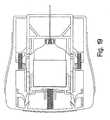
- FIG. 6is a side elevation of the device
- FIG. 7is an exploded illustration of the components of an exemplary embodiment of the device.
- FIG. 8is a plan view of the internal components of the device with one section of the housing removed, illustrating the components in a retracted configuration, in readiness for use;
- FIG. 9is an isometrical illustration of the actuator assembly
- FIG. 10is an enlarged illustration of one of the arm locks
- FIG 11is an enlarged plan illustration of one of the arm locks and its engagement with an arm of the actuator assembly and a spring for biasing the actuator assembly in a forward direction;
- FIG. 12is an enlarged illustration of one of the latching arrangements for retaining the syringe assembly in a retracted configuration, in readiness to be released;
- FIG. 13is an enlarged illustration, partly in sections, of the arrangement for supporting a hypodermic needle
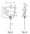
- FIG. 14is a front view of an embodiment of a syringe
- FIG. 15is a side view of the syringe of FIG. 14;
- FIG. 16is a sectional illustration of a portion of the plunger and container of the syringe body of FIG. 14 illustrating the seal between the two;
- FIGS. 17-22are sequential illustrations of the device in various stages of operation
- FIG. 23is an illustration of another exemplary embodiment of a device
- FIG. 24is an exploded illustration of the components of the device shown in FIG. 23 illustrating use of a syringe in the form of a collapsible bellows;
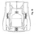
- FIG. 25is an illustration of the device of FIG. 24 with the front section of the housing removed and illustrating the configuration of the internal components in a retracted, storage configuration;
- FIG. 26is a diagrammatic illustration of a rupturable seal to isolate the contents of the bellows syringe of FIG. 25 from the needle;
- FIGS. 27-31are sequential illustrations of the device in various stages of operation.
- FIGS. 1-6illustrate a compact, low profile, auto-injector that includes a generally flat housing 10.
- the housingmay be defined by a pair of mating, separately formed housing sections, including a front section 12 and a back section 14.
- the front and back housing sections 12, 14may be formed from any appropriate material having sufficient strength to serve as a protective housing for the internal components of the device.
- the housing sectionsmay be made from a thin injection molded metal or high pressure casting or from various polymers or engineered materials having sufficient structural and engineering characteristics, including rigidity and toughness, to insure the integrity of the internal components.
- the internal surfaces of the housing sections 12, 14may be formed to include a number of walls and sockets that serve to cooperate with the internal components of the device to maintain the components in place as well as to guide movable components along their intended paths of movement.
- the auto-injectormay be considered as having a rear end 16 and a forward end 18 and a longitudinal axis extending between the ends.
- the deviceis intended to be held by its rearward portions, with the forward end 18 being pressed against the patient's skin, such as against the thigh. When triggered, the device causes the injection needle to emerge, suddenly, from the front end and effect injection of the medication bolus.
- a molded safety cover 20is fitted onto the forward end of the housing 10.
- the safety cover 20maintains the sterility of the internal components and also prevents inadvertent actuation of the device.
- the safety cover 20must be removed from the device before it can be used.
- the cover 20preferably is formed from a moldable polymeric material having sufficient strength to protect the front end of the housing even under rough conditions. The material also should be selected to enable the formation of a thin, tearable connector by which a peel-away strip 11 may be attached to the body of the cover.
- the cover 20may be transparent to enable the forward end of the housing including an actuator, described below, to be visible without removing the cap.
- the deviceis used in a simple three-step process, first by simply removing the peel-away strip 11, then gripping the rear end with one hand while removing the safety cover 20 with the other hand, and then pressing the exposed forward end of the device against the injection site.
- the outer surface of the housing 10may be provided with over-molded elastomeric grips 28, 30 having frictional characteristics for holding the device securely in one hand.
- the elastomeric material of the grips 28, 30may be provided with an appropriate filler to enable the device to glow in a dark environment.
- FIGS. 1 A, 1 B and 1Cillustrate, in enlarged detail, the configuration of the housing 10 and the manner in which it interacts with the cover 20 and peel-away strip 11.
- Each of the front and back sections 12, 14 of the housingis formed with a first circumferential groove 13 and a second circumferential groove 15 located close to but forwardly of the first groove 13.
- the first groove 13is intended to receive a latch portion 17 of the strip 11 (FIG. 1C).
- the second groove 15is receptive to a compressible member, such as a molded gasket or O-ring 19.
- the peel-away strip 11may be formed integrally with the cover 20, with the peel-away strip 11 being defined by a groove 21 formed circumferentially about the cover.
- the material of the cover 20 and peel-away strip 10preferably is selected to be of a suitable polymer capable of protecting the forward end of the housing while also being tearable manually at the thin neck 23.
- a tab 25preferably is integral with and extends from the peel-away strip 11 to facilitate gripping and tearing of the strip.
- the cover 20is assembled with the housing simply by inserting the forward end of the housing 10 into the rearwardly facing opening of the cover. As the peel-away strip 11 advances rearwardly toward the first groove 13, it rides over the compressible gasket 19.
- the lower, rearward facing edge of the locking element 17preferably is beveled, as at 27, to facilitate advancement of the peel-away strip 11 over and past the gasket 19.
- the lock portion 17 of the peel-away strip 11When the lock portion 17 of the peel-away strip 11 reaches the first groove, it snaps into the groove 13, preventing the cover from being removed until the strip 11 has been peeled away.
- the compressed gasket 19When the device is in its stored configuration (FIG. 1 C), the compressed gasket 19 provides a seal between the inner surface of the cover 20 and the outer surface of the housing 10 to provide a barrier against contamination.
- the flat configuration of the housingenables each of the front and back housing sections 12, 14 to receive a label.
- the labeling area of at least one of the sections, e.g., the back section 14,is of sufficient size to receive graphic images such as pictograms illustrating use of the device.
- the label 22Ahas three pictograms, 29, 31, 33 illustrating, respectively, removal of the peel-away strip 11, removal of the cover and pressing the forward end against the injection site. The use of such graphics enables even one unfamiliar with the device to understand immediately how it is used.
- the front and back sections 12, 14 of the housing 10may be secured together in a manner compatible with the particular materials from which the housing is made. For example, if the housing is made from an injection molded or cast metal, the sections may be secured together with screws 35 (FIG. 7) or an appropriate adhesive.
- the peripheral portions of the front and back sections 12, 14,may be sealed by interposing a thin gasket 37 between the facing surfaces of the peripheral walls of the housing sections. The gasket or O-ring 19 should maintain a seal where it contacts the thin gasket 37. Should the front and back housing sections be formed from a plastic or engineered material, the sections 12, 14 may be sealed by sonic welding, adhesives or other bonding agents, as appropriate.
- Each of the front and back housing sections 12, 14may be provided with a window 24, 26, respectively, through which the condition of the medication in the syringe can be observed.
- the condition of the medication in the syringeFor example, in the case of epinephrine, the presence of dark brown color or a precipitate in the medicine indicates that the strength of the medication has become reduced or that it has lost its therapeutic function, signaling that the medicine is not reliable and that the device should be replaced.
- the windowshould be formed from a material, or should be coated, to prevent exposure of the medication to quantities of ultraviolet light that might adversely effect its medicinal characteristics.
- the windowmay be modified or omitted. Omission of the window provides for additional flat surface on which labels may be placed appropriate to the particular medication or intended use of the device.
- the devicepreferably is dimensioned to be held in one's palm and may have peripheral dimensions approximating those of a conventional credit card.
- the housingmay be about 3.25 inches long, and about 2.0 inches wide.
- the thickness of the deviceis substantially less than either of the length or width and, in the preferred illustrative example, may be of the order of 0.25 inch thick.
- the device, so dimensionedhas a generally flat appearance. It is carried easily in ones pocket or purse without feeling bulky or uncomfortable thereby increasing the likelihood of it being carried on one's person and being available, if needed. It should be understood, however, the foregoing dimensions are illustrative only and that the precise dimensions and peripheral shape of the device may be varied as long as the device maintains its compact configuration and is not made so large as to defeat its compact and portable characteristics.
- flatwhen used in this specification to describe the housing of the device is intended to mean a configuration that can be confined in a virtual three dimensional envelope having a length, a width, and a thickness, and in which the thickness is substantially less than each of the length and width, with each of the length, width and thickness being measured along orthogonal directions.
- the embodiments described in this specificationmay be considered as having a generally rectangular peripheral configuration, other, non-rectangularly configured housings may be employed that have orthogonally measured length, width and thickness of a flat virtual envelope, as defined. It also should be understood that "flat” is not intended to be limited to precisely planar in a mathematical sense.
- the dimensions of the devicemay be varied while still maintaining the flat characteristic described in the specification.
- a range of lengths between about 2.8 to about 3.8 inchesmay be employed with a width in the range of about 1.7 to about 3.5 inches.
- the thickness of the devicemay be between about 0.20 to about 0.75 inch.
- FIGS. 7-15illustrate the internal components of an exemplary device embodying aspects of the invention.
- the devicemay be considered to include two longitudinally sliding assemblies, including an actuator assembly 32 and a syringe carrier assembly 34.
- the actuator assembly 32(FIG. 9), which may be formed from molded plastic mirror-image mating sections (see FIG. 8) in the same manner as the mating housing sections 12, 14, includes a generally flat needle shield 36 at its forward end and a trailing portion, such as a pair of arms 38 extending rearwardly from the shield 36.
- the needle shield 36has an internal needle passage 37 adapted to contain the forward end of the needle. The passage terminates, at its forward end at an opening 39.
- each arm 38includes a living hinge 40 by which a finger 42 is flexibly attached to the arm 38.
- Each finger 42includes a radially inwardly extending detent 44 that cooperates with the syringe carrier assembly 34 in a manner described below.
- the laterally outward surfaces of the arms 38are slidably guided by a pair of guide walls 46, formed integrally with the front and back housing sections 12, 14, and guide surfaces 48 formed at the forward end of the housing 10.
- the guide surfaces 48define a forward opening 49 in the housing through which a forward portion of the needle shield 36 projects.
- the actuator assembly 32is retained in the retracted position shown in FIG.
- the actuator 32or at least the portion of the needle shield 36 that projects forwardly of the housing before the device is actuated, may be formed from or provided with a label that has a visually distinct appearance from that of the housing, for example, by providing it with a red color or other warning indicia.
- the cover 20is transparent, the distinct forward portion of the shield is visible through the cover enhancing an understanding of the operation of the device merely from its appearance.
- the actuator assembly 32is biased in a forward direction by a pair of longitudinally disposed side compression springs 52.
- One end of each side spring 52is captured in a socket 54 defined by walls 49, 53 and the sidewalls 55 of the housing molded as part of the housing sections 12, 14.
- the other, forward, end of each side spring 52is captured in a socket 56 (FIG. 11) defined by each of a pair of outriggers 58 that extends laterally from its associated arm 38.
- the outermost end of each outrigger 58terminates in a guide member 60 that slides along and is guided by a longitudinally extending surface 62 of the sidewall formed by the mated housing sections 12, 14.
- each arm lock 50has a retained end 62 that may be U-shaped and is captured in a socket 64 formed by cooperative walls of each of the front and back housing sections 12, 14.
- the arm locks 50may be formed from a suitable plastic having characteristics that will enable it to perform its spring function.
- Each arm lock 50includes an extension 66 that functions in the manner of a resilient leaf spring. The end of each extension 66 has an inwardly projecting finger 68 that extends laterally inwardly through a distal aperture 51 formed in its associated arm 38 of the actuator assembly 32.
- the extension 66includes a flat section 72 that engages squarely a surface 70 (FIG. 11) that defines the aperture 51 in the arm 38.
- the tip of the finger 68extends inwardly beyond the inner surface 74 of the arm and defines an inclined, wedge surface 75 that, when engaged, trips the locks 50 and as described below, releases the arms 38, permitting the entire actuator assembly 32 to be driven distally under the influence of the side springs 52.
- the arm locks 50are tripped automatically when the injection needle has penetrated the patient's skin to the desired depth and the injection has been made.
- the syringe carrier assembly 34includes a syringe carrier 76 and a syringe 82, pre-filled with a selected injectable medication.
- the syringe carrier 76may be U-shaped, defined by an upper wall 78 and a pair of downwardly extending sidewalls 80.
- the syringe 82has a flat configuration and is defined by a flat plunger-type device comprising a cup-like container 84 having an open end 86 that receives a plunger 88 that carries an injection needle 90.
- the syringe carrier 76is connected securely to the syringe, for example, by dimensioning the container 84 and carrier 76 to provide a snug friction fit which may be supplemented by lugs 85 extending from the carrier sidewalls 80 that engage the forward edge of the container.
- the container 84preferably is formed from glass and is transparent so that its front and back faces 92, 94 (FIG. 15) may serve as windows.
- the windowsare located to be aligned with the windows 24, 26 on the front and back housing sections 12, 14, when the device is in its retracted configuration (FIG. 8). In that manner, the user may observe the contained liquid through the windows to determine visually its condition. This is particularly important with a medication which changes color or forms a precipitate when its medicinal effectiveness has been reduced or lost.
- the container 84may be formed from a variety of other materials that are compatible with the particular medication to be contained.
- the container 84has a flat configuration in which the thickness T of the container is substantially less than either of its length L or width W (see FIGS. 14, 15).
- the container 84has front and back walls 92, 94 joined by a peripheral wall 96 that is securely engageable by the syringe carrier 76.
- the open end 86 of the containerfaces forwardly and is closed by the flat plunger 88 that is slidable into the container 84.
- the plunger 88engages the internal surfaces of the front and back walls 92, 94 as well as the side portions 98 of the peripheral wall 96.
- the outer surface of the plungershould be slidably sealed to the container as by providing the plunger with one, and preferably several, wiping ribs100 that extend about the plunger 88 to engage with the internal surfaces of the walls 92, 94, 96 (FIG. 16).
- the peripheral wallmay be radiused, if desired, to facilitate an enhanced seal between the container 84 and plunger 88.
- the plungeritself may be solid or hollow, depending on the volume of medication to be contained and should be formed from a material that is compatible with the contained medicine, such as rubber or other compositions of the type used in conventional tubular syringes.
- the hollow plunger illustrated in FIGS. 14 and 15may be considered as having front and back walls 102, 104 and a peripheral wall 106
- the rear end 108 of the plunger 88is open to communicate with the interior of the container
- the forward end of the plunger 88includes a needle carrier 110 by which the injection needle 90 is held in spaced alignment with a septum 112 that forms a seal at the forward end of the plunger (FIG. 13).
- the septum 112completely closes the forward end of a passage 114 that extends through the wall of the plunger and communicates with the interior volume of the syringe.
- the needle carrier 110may include a pair of longitudinally collapsible, forwardly extending, accordion-like supports 116 that may be biased in a distally extended configuration, by a compression spring 118.
- the double-ended needle 90may be secured to an anchor 122 that can be embedded, together with a portion of the needle, in the needle support 120.
- the sharp rear tip of the needleshould be non-coring, and is supported in slightly spaced relation to the forward side of the septum 112.
- the sharp rear end of the needle 90is maintained in spaced relation to the outer surface of the septum 112 by the compression spring 118 that extends between the septum 112 and the needle support 120.
- the rear end of the compression spring 124may be retained in place by a boss 126 formed about the forward face of the septum 112 and adapted to engage the rear end of the compression spring 124.
- the forward end of the spring 124is tapered and bears against the needle support, with the spring surrounding the forward end of the needle 90.
- syringeis intended to mean a syringe body adapted to contain injectable medicine in which the body has an interior collapsible volume with a hypodermic needle carried by the syringe body and being connected or connectible to the interior chamber to enable mediation to be injected from the container through the needle into the patient.
- the above definition of "flat" when used to describe the syringe 82is intended to have the same meaning as that discussed above in connection with the configuration of the housing, namely, as referring to a syringe body containable within a virtual envelope having a length, a width, and a thickness and in which the thickness is substantially less than each of the length and width, with each of the length, width and thickness being measured along directions orthogonally related to the others.
- the described arrangement of the syringe 82may be considered to comprise a flat syringe.
- two specific configurations of flat syringesare described in this specification, it should be understood that other syringe configurations, containable in the flat housing, may be employed in the practice of the invention.
- the syringe assembly 34is restrained in its retracted position by engagement of a pair of latches 128 formed as part of the syringe carrier 76.
- Each of the latches 128extends in a laterally outward direction and engages the detent 44 of one of the fingers 42 of the actuator assembly.
- Each of the fingers 42is biased into locked engagement with the latch 128 by a latch spring 130.
- the latch spring 130may include a base portion 132 which is secured in a socket 134 molded into the housing sections 12, 14, and a resilient member 136 that extends from the base 132 into engagement with the outwardly facing surface 138 of the finger 42.
- the free end 140 of each finger 42may be beveled, as indicated at 140.
- the beveled free end 140is biased into engagement with a wall 142 that includes a camming surface 144.
- the camming surface 144is oriented with respect to its associated finger 42 to guide the finger 42 to pivot outwardly (clockwise as seen in FIG. 12) about the hinge 40 as the actuator assembly 32, including the finger 42, is moved slightly to a more retracted, proximal position.
- Such movementinitiated by pressing the forward end of the actuator against the injection site causes the fingers 42 to pivot outwardly, disengaging each detent 44 from its associated latch 128, and freeing the syringe assembly 34 for forward movement.
- the syringe assemblyis biased for such movement by an injector compression spring 146.
- the injector spring 146is retained, at its rear end, in a socket 148 formed integrally with the housing sections 12, 14. The forward end of the spring 146 bears against the upper wall 78 of the syringe assembly 34 where it is held by providing the upper wall with a retention boss or socket 150 engageable with the spring 112 (FIG. 8).
- the injector springfor some applications, especially those of an emergency nature, should develop enough force to drive the needle through clothing, in addition to tissue.
- the injector spring 146is configured so that with the actuator and syringe assemblies 32, 34 in the locked configuration (FIG. 8), the injector spring 112 is capable of a small amount of further longitudinal compression. The extent of additional longitudinal compression should enable the actuator and syringe assemblies 32, 34 to be retracted sufficiently to withdraw the detents 44 from locked engagement with the latches 128. When the latches 128 have been released, the syringe assembly 34 is released and is driven immediately and forcefully in a forward direction by the injector spring 146. The syringe assembly 34 is guided in that movement by engagement of the outer surfaces 152 of its sidewalls 80 with the inner surfaces 74 of the arms 38 of the actuator assembly 32.
- the sharp, forward tip of the injection needle 90projects longitudinally through an aperture 154 in the needle shield 36 and beyond the forward end 156 of the needle shield 36.
- the forward end 156remains pressed firmly against the user's skin and the force of the injector spring 146 will drive the needle 90 into the patient's tissue to an intended depth.
- the selected depth of needle penetrationwill depend, in part, on the type of medication to be injected and whether it is to be an intramuscular or subcutaneous injection. The depth of needle penetration is determined by the length of the needle and the needle shield as well as location of the needle when its forward advancement is terminated.
- forward movement of the needleterminates when the needle support 120 engages the rear face 158 of the needle shield 36.
- the actuator assembly 32remains locked in place by engagement of the arm locks 50 with the forward sockets 51 in the arms 38 of the actuator assembly 32.
- the needle support 120will have bottomed on the rear face 158 of the needle shield 36 and the needle carrier 110 will begin to collapse, advancing the syringe body, including the septum 112, toward the rear end of the needle. Continued advancement causes the septum 112 to impale itself on the needle 90, establishing flow communication between the needle and the interior of the syringe.
- the plunger 88can no longer advance forwardly.
- the container 84is free to continue forward advancement sliding over the plunger, under the continued force of the spring 146 and, in so doing, the internal volume of the syringe is compressed, causing ejection of a bolus of medication through the needle into the patient.
- the syringemay contain a greater volume of medication than the actual volume of the dose to be injected.
- the medicationis epinephrine, (1:1000) an adult dose is considered to be 0.3 ml.
- the stability of the epinephrineis improved when it is stored in a larger volume of about 2.0 ml. Therefore, the extent to which the internal volume of the syringe can compress may be limited to assure injection only of the desired dose.
- the volume of the injected dosemay be limited by limiting the extent to which the internal volume of the syringe can be compressed.
- abutment surface 160is provided internally of the housing.
- the abutment surface 160is located to be in alignment with a forwardly facing surface 162 at the end of each of the container carrier sidewalls 80.
- forward movement of the container 84is terminated, thus terminating the ejection stroke.
- Another approach to limiting the extent to which the syringe volume can be compressedis to dimension the container 84 and plunger 88 so that the rearward face 108 of the plunger bottoms out on the inner face of the rear portion 109 of the peripheral wall of the container 84.
- the actuator assembly 32is restrained from moving forward relative to the housing 10 by engagement of the arm locks 50 with the arms 38. Engagement of the arm locks 50 with the arms 38 also serves to limit the extent of rearward travel of the actuator assembly during the initial triggering operation, as the forward surface 156 of the shield 36 is pressed against the injection site.
- the protruding ends 68 of the arm locks 50are engaged by a portion of the container assembly, such as a portion of the lower ends 160 of the sidewalls 80 of the container carrier 76, thereby tripping the arm locks 50 to disengage from the arms 38 and permit the actuator assembly 32 to be driven forwardly with respect to the housing 10 under the influence of the side springs 52.
- the outwardly facing surfaces 164 of the needle shield 36 that project beyond the forward end 15 of the housing 10 after the device has been usedalso provide a wide, flat area receptive to labeling 165 (FIG. 7) or other imprint with sharps biohazard warning symbols 166 (FIG. 8).
- the biohazard warning symbol 166preferably is placed on the portion 168 of the more rearward surface of the needle shield that is exposed only when the shield has been extended to its post-injection, needle covering position.
- another detent aperture 170is formed in each of the arms 36 rearward of the apertures 51, to receive and engage the latch 50 when the actuator assembly 32 and needle shield 36 have been projected to fully cover the needle 90.
- FIGS. 17-22illustrate the above-described device in various stages of operation.
- the syringe carrierwill be released from its latched position to be driven distally under the influence of the drive spring 112with sufficient force to cause the needle to pierce the skin and penetrate the tissue to the intended depth (FIG. 18).
- the needle platform 120abuts the surface 158, the sharp forward end of the needle will have penetrated the patient's tissue to the intended depth.
- the continued influence of the drive spring 146drives the syringe carrier and the syringe, as a unit, forwardly, to cause the septum 112 to impale itself on the sharp rear end of the needle, communicating the lumen of the needle with the medication contained in the syringe.
- the supports 116collapse until forward movement of the plunger 84 has terminated.
- the continued influence of the drive spring 146will advance the syringe carrier and container 84 forwardly over the then-stationary plunger, collapsing the volume within the syringe and causing a bolus of the medicine to be injected into the patient (FIG. 26). Injection terminates when the compression of the syringe volume is terminated.
- the arm locks 50are tripped. With the actuator assembly arms 38 freed, the actuator assembly will advance forwardly relative to the housing under the influence of the side springs 52, as the device is withdrawn (FIG. 21).
- the needle shield 36will be extended to cover and protect the forward end of the needle, with the arm latches 50 dropping into the rear apertures 170 to lock the actuator assembly 32 and needle shield 36 in the distally extended, needle protecting configuration (FIG. 22).
- the needle shieldextended in its distal, locked position, the biohazard indicia 166 on the flat faces of the shield are exposed prominently to serve their warning function.
- a compact, portable, pre-filled, single use auto-injectoris not limited to administration of medicine for treatment of anaphylactic reaction.
- medicinefor treatment of anaphylactic reaction.
- the medication to be injectedmay be one serving somewhat of an emergency function, such as administration of epinephrine, morphine, atropine, cardiotonic medication, anti-seizure medicines as for treatment of status epilepticus, antitoxins, anticoagulants and the like.
- Other medications deliverable by auto-injectormay be more in the nature of convenience, such as administration of anti-migraine medication (e.g., sumatriptan or ergonovine), vaccines, growth hormone, antibiotics, injectable vitamins, and contraceptives, among others.
- anti-migraine medicatione.g., sumatriptan or ergonovine
- Injectable medicationsmay also include anticholinergic medication (atropine), anti-arrhythmics (e.g., lidocaine, amiodarome), drugs for the treatment of multiple sclerosis (e.g., interferon), cholinomimetics (e.g., neostigmine), anti-nausea and gastrointestinal stimulants (e.g., metoclopramide), diuretics (e.g., furosemide), sedatives and hynotics (e.g., hydroxyzine), anti-psychotic agents (e.g., haloperidol), analgesics (e.g., morphine), hypocalcimic drugs (e.g., calcitonin), corticosteroids (e.g., methyl prednisolone), anxiolytics (e.g., diazepam), insulin, erythropoietin, colony stimulating factor (e.g., Filgrastim),
- FIGS. 23-29illustrate another embodiment of the device in which the syringe includes walls that are collapsible in an accordion-like fashion.
- the actuator assembly and syringe carriermay be considered as substantially the same as in the previously described embodiment.
- elements in this embodiment that are identical to those in the previously described embodimentwill be designated with the same reference numeral.
- the reference numeralwill be the same with a prime mark (').
- new reference numeralsare used.
- the housingincludes a peripheral configuration in which the rear portion is wider than the forward portion. It should be understood that although the previously described embodiment had a housing with peripheral dimensions approximating a rectangle, it may be desirable in some instances to configure the housing so that its rear end is wider or more narrow than its forward end. Indeed, the configuration of the housing may include non-rectangular peripheral geometries that, nonetheless, are flat and are containable within the defined flat virtual envelope.
- the syringe 200may be considered as having a relatively rigid, shape-retaining rear portion 202 adapted to fit securely within the generally rectangular opening defined by the U-shaped container carrier 76.
- the rearward portion 202 of the syringe 200may be provided with a pair of windows 201, 203 on its front and rear surfaces, as by forming the syringe body from a transparent material such as polyethylene terephthalate (PET).
- PETpolyethylene terephthalate
- the windowsare located to be aligned with the windows 24', 26' on the front and rear housing sections 12', 14', when the device is in its retracted configuration (FIG. 25).
- the syringemay be formed, as by blow molding.
- the syringe bodyhas a flat configuration, as defined.
- the forward portion 204 of the syringe 200in this exemplary embodiment, is collapsible and may be molded or otherwise formed in a collapsible bellows arrangement.
- the forward portions of the syringe 200includes a sufficiently sturdy bottom wall 206 to provide a secure mount for a hypodermic needle 90'.
- the needle 208extends longitudinally in a forward direction and terminates in a sharp tip. The medication is pre-loaded and sealed within the syringe body 200 when the device is fabricated so that it is not exposed to the lumen of the injection needle 208 until the device has begun its operation.
- a pressure rupturable membrane 210may be disposed within the syringe 200 over the rear end of the needle 90' (FIG. 26).
- the membrane 210will rupture to immediately communicate the interior of the syringe 200 with the lumen of the injection needle 90'.
- other sealing arrangementsmay be employed, including arrangements in which the proximal end of the hypodermic needle pierces a sealing septum just before injection is to be completed as described in connection with the previous embodiment.
- the continued forwardly directed force of the injector spring 146initiates longitudinal collapse of the syringe 200 and decrease of its internal volume.
- the rupturable membrane 210 that seals the containerwill burst when the pressure within the container has reached a predetermined design limit.
- the membrane 210ruptures, communication between the interior of the syringe and the lumen of the hypodermic needle 90 is established such that continued collapse of the syringe 200 under the influence of the injection spring146 will force the liquid medication through the needle 90 into the patient.
- the force of the injector spring 146is selected to be sufficient to cause the desired volume of medication to be injected into the patient in a rapidly delivered bolus.
- the extent to which the syringe 200 is compressedcan be limited by engagement of the forward end 162 of the syringe carrier 34 with the abutment surface 160 on the actuator assembly 32'.
- FIGS. 27-31illustrate the above-described device in various stages of operation.
- FIG. 27illustrates the device when it has been pressed against the patient's thigh to push the actuator assembly rearwardly into the housing 10 to an extent sufficient to release the latch 128' to initiate the needle penetration phase.
- FIG. 28illustrates the components of the device when the injection spring 146 has advanced the syringe assembly distally to the point in which the forward end of the syringe body 200 (e.g., the bottom wall 206 of the bellows in this embodiment) is advanced into engagement with the abutment surface 158' of the actuator assembly.
- the forward end of the syringe body 200e.g., the bottom wall 206 of the bellows in this embodiment
- the needle 208will have been projected beyond the forward end 156' of the needle shield 36' and will have penetrated into the patient's tissue to the predetermined depth and the injector spring 146 and syringe carrier will continue to advance to the stage illustrated in FIG. 29.
- the bellows 204is compressed, first causing a build-up of pressure within the syringe body sufficient to effect communication with the lumen of the needle 208 and then to forcefully inject the bolus of medication through the needle and into the patient.
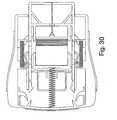
- FIG. 30illustrates the device after the injection phase has been completed, with the latches 50 having been tripped.
- the actuator assembly 34is released and is driven forwardly by the springs 52, causing the rearward portion of the needle shield 36' to project beyond the forward end of the housing.
- the forward end 156' of the needle shieldis maintained in contact with the patient's skin throughout that motion so that the shield progressively covers the needle 208 as the housing 10' is drawn away from the skin.
- the actuator assemblywill have advanced forwardly relative to the housing to the point where the latches 50 snap into engagement with the rear sockets 126 on the arms 38. With the latches so reengaged, the actuator assembly is locked in a position in which the needle shield cannot be urged back into the housing. In this configuration, the rear portion of the shield on which a label bearing the biohazard icon will be exposed, indicating that the device has been used and that it contains a biohazard sharp.
- an auto-injectorhaving a flat housing; an auto-injector having a broad flat surface with easily understood pictograms of sufficient size to enhance immediate understanding of the manner of use of the device; an auto-injector for rapid bolus delivery having a flat housing dimensioned to be less bulky and easily carried on one's person; a needle shield for an auto-injector that is of a generally flat configuration to present a broad face adapted to carry a label with indicia evident of a biohazard; an auto-injector with a housing having elastomeric grips embedded with a material to cause the grips to glow in a darkened environment; an auto-injector in which the injection needle and actuation member are located at the same end of the housing of the device and where the actuator
Landscapes
- Health & Medical Sciences (AREA)
- Engineering & Computer Science (AREA)
- Life Sciences & Earth Sciences (AREA)
- Animal Behavior & Ethology (AREA)
- Anesthesiology (AREA)
- Biomedical Technology (AREA)
- Heart & Thoracic Surgery (AREA)
- Hematology (AREA)
- Veterinary Medicine (AREA)
- Vascular Medicine (AREA)
- General Health & Medical Sciences (AREA)
- Public Health (AREA)
- Environmental & Geological Engineering (AREA)
- Infusion, Injection, And Reservoir Apparatuses (AREA)
- Electrical Discharge Machining, Electrochemical Machining, And Combined Machining (AREA)
- Catching Or Destruction (AREA)
Abstract
Description
- 1. The invention relates to portable auto-injectors for rapid, automatic injection of a measured dose of medication.Background
- 2. Certain medical conditions require immediate injection of medication. The condition requiring such treatment may result from a variety of causes. Among the most serious of those conditions is anaphylaxis (a severe allergic reaction) that, in many cases, can become fatal within minutes if left untreated. Among the numerous allergens that may cause anaphylaxis are insect bites, various chemical substances and foods. Food products having even small quantities of peanuts, seafood or milk products can, in some individuals, induce severe, potentially lethal reactions. In foods, the allergen may be "hidden", that is, the food, unknowingly, may contain a minute trace of an allergenic ingredient or may have been exposed to the allergenic ingredient during its processing. When anaphylaxis occurs, often there is insufficient time for the patient to reach a hospital or other trained and equipped medical personnel.
- 3. Individuals known to be at risk for anaphylactic reaction typically are advised to carry, at all times, an auto-injection device adapted to inject a bolus of epinephrine. The ability to inject the epinephrine immediately can be a matter of life or death. Notwithstanding the severe risk involved, there is evidence that a large proportion of the population that should be carrying such a device, in fact, does not. At least one study indicates that fewer than 30% of patients at risk of anaphylaxis carry the device at all times. SeeGoldberg A, Confino-Cohen R., "Insect Sting-Inflicted Systemic Reactions: Attitudes of Patients With Insect Venom Allergy Regarding After-Sting Behavior and Proper Administration of Epinephrine", J Allergy Clin lmmonol 2000; 106:1184-9. Food based allergies are reported to cause anaphylactic reactions resulting in 30,000 trips to the emergency room and 150 to 200 deaths per year (www.foodallergy.com). The main factor contributing to a fatal outcome is the fact that the victims did not carry their emergency kit with adrenaline (epinephrine). SeeWuthrich, B., "Lethal or Life Threatening Allergic Reactions to Food", J. Investig Allergol Clin Immunol, 2000 Mar-Apr, 10(2):59-65. Moreover, even for those individuals that are required to carry such a device, it has been reported that a large proportion (as much as two-thirds) are insufficiently familiar with its use and operation. SeeSicherer, S.H., Forman, J.A., Noone, S.A., "Use Assessment of Self-Administered Epinephrine Among Food-Allergic Children and Pediatricians", Pediatrics, 2000; 105:359-362. Only 25% of physicians, in one study, were able to properly demonstrate the use of the device. SeeGrouhi, M., Alsherhri, M., Hummel, D, Roifman, C.M., "Anaphylaxis and Epinephrine Auto-Injector Training: Who Will Teach the Teachers?, Journal of Allergy and Clinical Immunology 1999 July; 104(1):190-3. It has been estimated that as many as forty million individuals in the United States are at risk of anaphylaxis. SeeNeugut, A.l., Ghatak, A.T., and Miller, R.L., "Anaphylaxis in the United States: An Investigation into its Epidemiology", Archives of Internal Medicine 2001 Jan 8; 161(1): 15-21.
- 4. Perhaps the most common automatic emergency epinephrine injection device is commercially available from DEY, Inc. of Napa, California under the trade designation EpiPen. The EpiPen device, believed to be described in
U.S. patent 4,031,893 , is designed to inject rapidly an adult dose of about 0.30 milligrams of epinephrine. The device is generally tubular and, including its tubular container, is about six inches long and nearly one inch in diameter. The device is relatively bulky and requires several manipulative steps in its use. Where a patient may only actually use the device infrequently, there may be some confusion in performing the required manipulative steps, particularly when the individual experiencing an anaphylactic reaction may be in a state of near panic. Although the device includes written instructions on its cylindrical surface, they may not be easily read, particularly under the stress of emergency circumstances. The manner in which the EpiPen is to be used is not readily and intuitively apparent without reading the text of the instructions on the cylindrical sleeve. Should it be necessary for someone other than the patient (e.g., a bystander) to administer the medication, for example, if the patient has gone into shock, the person called on to administer the medication may not know how to operate the auto-injection device. Consequently, precious time may be lost, increasing the risk to the patient. Additionally, after the device has been used to effect an injection, its hypodermic needle remains exposed, presenting post-injection hazards. Among such hazards are those associated with blood-born diseases such as HIV and hepatitis B and C or, when some of the medication remains in the device after injection, the risk of delivering some of the residual medication as a consequence of an accidental needle stick. - 5. It would be desirable to provide a more compact, low profile, easily used auto-injector for rapid transcutaneous administration of a predetermined dose of medication.
- 6. Our single-use, auto-injector for rapid delivery of a bolus of medication is configured to have a generally flat sealed housing with peripheral dimensions approximating those of a credit card to facilitate the ease and convenience of carrying, handling and using the device. The housing contains internal components configured and arranged to be in a generally flat array and to operate within the generally flat confines of the housing. The internal components include a syringe that is pre-filled with the selected injectable medication, the syringe including a syringe body and a hypodermic needle. The syringe is arranged to be moveable from a retracted, pre-injection position in which the device is stored, to an extended, injection position in which the needle extends out of the housing to penetrate tissue. The syringe itself is configured to be containable within a flat virtual envelope. A needle shield also may be carried by the housing to cover and enclose the hypodermic needle at all times before, during and after injection, so that the sharp tip of the needle is never exposed. The shield also may serve as an actuator, responsive to being pressed against the injection site to enable the needle to be driven from its retracted position to its injection position, first to pierce the patient's skin to the desired depth and then to inject automatically and rapidly a measured bolus of medication into the patient. When the device is actuated, the syringe is released from its retracted position to enable a self-contained power source first to drive the syringe toward the injection position and then to effect the injection of the medication. After injection, as the device is withdrawn from the patient, the needle shield automatically extends to a position to cover the needle. The device automatically locks the needle shield in its extended, needle-protective position. In another aspect, the generally flat configuration of the device provides ample space on which relatively large, easily understood, pictograms can be placed, graphically showing the manner of using the device or for providing other information.
- 7. The auto-injector includes a cover that is secured to the housing to contain and seal the injection end of the device, including the needle shield, during storage and before use. The cover is sealed to the housing and protects the device from inadvertent actuation. It must be removed in order to permit injection which is effected by then simply pressing the needle shield against the patient's skin. The cover may be transparent to enable the actuating member to be seen. The device may include a removable tamper-evident seal between the cover and the body of the device to further assure sterility and protection of the device before use.
- 8. It is among our general objects to provide a compact, portable, low-profile, safety, single use, auto-injector for rapidly administering a bolus of injectable medication and methods for rapid self-administration of medication. Other objects, advantages, aspects and features will be apparent to those skilled the art from the following, more detailed, description.
- 9. In the accompanying drawings:
- 10. FIG. 1 is an isometric view of an exemplary embodiment of an auto-injector, illustrating the back face of the housing and a large, flat labeling area;
- 11. FIG. 1A is an enlarged illustration of a peel-away strip connecting the cover to the body of the auto-injector;
- 12. FIG. 1 B is an enlarged cross-sectional illustration of the body of the injector illustrating the seal and groove on the auto-injector body adapted to receive and engage the cover;
- 13. FIG. 1C is a cross-sectional illustration similar to FIG. 1 B showing the cover engaged with the body, sealed and locked;
- 14. FIG. 2 is a plan view of the front of the device;
- 15. FIG. 3 is a plan view of the back of the device;
- 16. FIG. 4 is an end view of the rear of the device;
- 17. FIG. 5 is an end view of the front of the device with the cover attached to the housing;
- 18. FIG. 6 is a side elevation of the device;
- 19. FIG. 7 is an exploded illustration of the components of an exemplary embodiment of the device;
- 20. FIG. 8 is a plan view of the internal components of the device with one section of the housing removed, illustrating the components in a retracted configuration, in readiness for use;
- 21. FIG. 9 is an isometrical illustration of the actuator assembly;
- 22. FIG. 10 is an enlarged illustration of one of the arm locks;
- 23. FIG 11 is an enlarged plan illustration of one of the arm locks and its engagement with an arm of the actuator assembly and a spring for biasing the actuator assembly in a forward direction;
- 24. FIG. 12 is an enlarged illustration of one of the latching arrangements for retaining the syringe assembly in a retracted configuration, in readiness to be released;
- 25. FIG. 13 is an enlarged illustration, partly in sections, of the arrangement for supporting a hypodermic needle;
- 26. FIG. 14 is a front view of an embodiment of a syringe;
- 27. FIG. 15 is a side view of the syringe of FIG. 14;
- 28. FIG. 16 is a sectional illustration of a portion of the plunger and container of the syringe body of FIG. 14 illustrating the seal between the two;
- 29. FIGS. 17-22 are sequential illustrations of the device in various stages of operation;
- 30. FIG. 23 is an illustration of another exemplary embodiment of a device;
- 31. FIG. 24 is an exploded illustration of the components of the device shown in FIG. 23 illustrating use of a syringe in the form of a collapsible bellows;
- 32. FIG. 25 is an illustration of the device of FIG. 24 with the front section of the housing removed and illustrating the configuration of the internal components in a retracted, storage configuration;
- 33. FIG. 26 is a diagrammatic illustration of a rupturable seal to isolate the contents of the bellows syringe of FIG. 25 from the needle; and
- 34. FIGS. 27-31 are sequential illustrations of the device in various stages of operation.
- 35. FIGS. 1-6 illustrate a compact, low profile, auto-injector that includes a generally
flat housing 10. The housing may be defined by a pair of mating, separately formed housing sections, including afront section 12 and aback section 14. The front andback housing sections housing sections - 36. The auto-injector may be considered as having a
rear end 16 and aforward end 18 and a longitudinal axis extending between the ends. The device is intended to be held by its rearward portions, with theforward end 18 being pressed against the patient's skin, such as against the thigh. When triggered, the device causes the injection needle to emerge, suddenly, from the front end and effect injection of the medication bolus. - 37. A molded
safety cover 20 is fitted onto the forward end of thehousing 10. Thesafety cover 20 maintains the sterility of the internal components and also prevents inadvertent actuation of the device. Thesafety cover 20 must be removed from the device before it can be used. Thecover 20 preferably is formed from a moldable polymeric material having sufficient strength to protect the front end of the housing even under rough conditions. The material also should be selected to enable the formation of a thin, tearable connector by which a peel-away strip 11 may be attached to the body of the cover. Thecover 20 may be transparent to enable the forward end of the housing including an actuator, described below, to be visible without removing the cap. The device is used in a simple three-step process, first by simply removing the peel-away strip 11, then gripping the rear end with one hand while removing thesafety cover 20 with the other hand, and then pressing the exposed forward end of the device against the injection site. The outer surface of thehousing 10 may be provided with over-moldedelastomeric grips grips - 38. FIGS. 1 A, 1 B and 1C illustrate, in enlarged detail, the configuration of the
housing 10 and the manner in which it interacts with thecover 20 and peel-away strip 11. Each of the front andback sections circumferential groove 13 and a secondcircumferential groove 15 located close to but forwardly of thefirst groove 13. Thefirst groove 13 is intended to receive alatch portion 17 of the strip 11 (FIG. 1C). Thesecond groove 15 is receptive to a compressible member, such as a molded gasket or O-ring 19. The peel-away strip 11 may be formed integrally with thecover 20, with the peel-away strip 11 being defined by agroove 21 formed circumferentially about the cover. Thegroove 21, in turn, defines a thin circumferential connector 23. The material of thecover 20 and peel-away strip 10 preferably is selected to be of a suitable polymer capable of protecting the forward end of the housing while also being tearable manually at the thin neck 23. Atab 25 preferably is integral with and extends from the peel-away strip 11 to facilitate gripping and tearing of the strip. Thecover 20 is assembled with the housing simply by inserting the forward end of thehousing 10 into the rearwardly facing opening of the cover. As the peel-away strip 11 advances rearwardly toward thefirst groove 13, it rides over thecompressible gasket 19. The lower, rearward facing edge of the lockingelement 17 preferably is beveled, as at 27, to facilitate advancement of the peel-away strip 11 over and past thegasket 19. When thelock portion 17 of the peel-away strip 11 reaches the first groove, it snaps into thegroove 13, preventing the cover from being removed until thestrip 11 has been peeled away. When the device is in its stored configuration (FIG. 1 C), thecompressed gasket 19 provides a seal between the inner surface of thecover 20 and the outer surface of thehousing 10 to provide a barrier against contamination. - 39. The flat configuration of the housing enables each of the front and
back housing sections back section 14, is of sufficient size to receive graphic images such as pictograms illustrating use of the device. As shown in FIG. 3, thelabel 22A has three pictograms, 29, 31, 33 illustrating, respectively, removal of the peel-away strip 11, removal of the cover and pressing the forward end against the injection site. The use of such graphics enables even one unfamiliar with the device to understand immediately how it is used. - 40. The front and
back sections housing 10 may be secured together in a manner compatible with the particular materials from which the housing is made. For example, if the housing is made from an injection molded or cast metal, the sections may be secured together with screws 35 (FIG. 7) or an appropriate adhesive. The peripheral portions of the front andback sections thin gasket 37 between the facing surfaces of the peripheral walls of the housing sections. The gasket or O-ring 19 should maintain a seal where it contacts thethin gasket 37. Should the front and back housing sections be formed from a plastic or engineered material, thesections - 41. Each of the front and
back housing sections window - 42. The device preferably is dimensioned to be held in one's palm and may have peripheral dimensions approximating those of a conventional credit card. In a preferred illustrative example, the housing may be about 3.25 inches long, and about 2.0 inches wide. The thickness of the device is substantially less than either of the length or width and, in the preferred illustrative example, may be of the order of 0.25 inch thick. The device, so dimensioned, has a generally flat appearance. It is carried easily in ones pocket or purse without feeling bulky or uncomfortable thereby increasing the likelihood of it being carried on one's person and being available, if needed. It should be understood, however, the foregoing dimensions are illustrative only and that the precise dimensions and peripheral shape of the device may be varied as long as the device maintains its compact configuration and is not made so large as to defeat its compact and portable characteristics.
- 43. The term "flat" when used in this specification to describe the housing of the device is intended to mean a configuration that can be confined in a virtual three dimensional envelope having a length, a width, and a thickness, and in which the thickness is substantially less than each of the length and width, with each of the length, width and thickness being measured along orthogonal directions. Although the embodiments described in this specification may be considered as having a generally rectangular peripheral configuration, other, non-rectangularly configured housings may be employed that have orthogonally measured length, width and thickness of a flat virtual envelope, as defined. It also should be understood that "flat" is not intended to be limited to precisely planar in a mathematical sense.
- 44. Although the most preferred embodiment has peripheral dimensions approximating those of a credit card (2.125" x 3.375") and a thickness of about 0.25 inch, the dimensions of the device may be varied while still maintaining the flat characteristic described in the specification. Preferably, a range of lengths between about 2.8 to about 3.8 inches may be employed with a width in the range of about 1.7 to about 3.5 inches. The thickness of the device may be between about 0.20 to about 0.75 inch.
- 45. FIGS. 7-15 illustrate the internal components of an exemplary device embodying aspects of the invention. The device may be considered to include two longitudinally sliding assemblies, including an
actuator assembly 32 and asyringe carrier assembly 34. The actuator assembly 32 (FIG. 9), which may be formed from molded plastic mirror-image mating sections (see FIG. 8) in the same manner as themating housing sections flat needle shield 36 at its forward end and a trailing portion, such as a pair ofarms 38 extending rearwardly from theshield 36. Theneedle shield 36 has aninternal needle passage 37 adapted to contain the forward end of the needle. The passage terminates, at its forward end at anopening 39. The trailing end of eacharm 38 includes a livinghinge 40 by which afinger 42 is flexibly attached to thearm 38. Eachfinger 42 includes a radially inwardly extendingdetent 44 that cooperates with thesyringe carrier assembly 34 in a manner described below. The laterally outward surfaces of thearms 38 are slidably guided by a pair ofguide walls 46, formed integrally with the front andback housing sections surfaces 48 formed at the forward end of thehousing 10. The guide surfaces 48 define aforward opening 49 in the housing through which a forward portion of theneedle shield 36 projects. Theactuator assembly 32 is retained in the retracted position shown in FIG. 8 by a pair of releasable arm locks 50 that are mounted interiorly of the housing and releasably engageforward apertures 51 formed in thearms 38 of the actuator assembly 32 (FIGS. 8 and 9). When theactuator assembly 32 is in its retracted position (FIG. 8), the forward portion of theneedle shield 36 projects slightly beyond theforward end 15 of thehousing 10. When thecover 20 is separated from the housing, the forward end of theneedle shield 36 is exposed and serves as an actuator to initiate operation of the device, when pressed against the patient's skin. Theactuator 32, or at least the portion of theneedle shield 36 that projects forwardly of the housing before the device is actuated, may be formed from or provided with a label that has a visually distinct appearance from that of the housing, for example, by providing it with a red color or other warning indicia. When thecover 20 is transparent, the distinct forward portion of the shield is visible through the cover enhancing an understanding of the operation of the device merely from its appearance. - 46. The
actuator assembly 32 is biased in a forward direction by a pair of longitudinally disposed side compression springs 52. One end of eachside spring 52 is captured in asocket 54 defined bywalls sidewalls 55 of the housing molded as part of thehousing sections side spring 52 is captured in a socket 56 (FIG. 11) defined by each of a pair ofoutriggers 58 that extends laterally from its associatedarm 38. The outermost end of eachoutrigger 58 terminates in aguide member 60 that slides along and is guided by alongitudinally extending surface 62 of the sidewall formed by the matedhousing sections springs 52 can be compressed further in order to permit theentire actuator assembly 32 to move slightly proximally to trigger the injection procedure, as described below. - 47. The
actuator assembly 32 is releasably maintained in the retracted configuration shown in FIG. 8 by the releasable arm locks 50. As shown in enlarged detail in FIG. 10 eacharm lock 50 has a retainedend 62 that may be U-shaped and is captured in asocket 64 formed by cooperative walls of each of the front andback housing sections arm lock 50 includes anextension 66 that functions in the manner of a resilient leaf spring. The end of eachextension 66 has an inwardly projectingfinger 68 that extends laterally inwardly through adistal aperture 51 formed in its associatedarm 38 of theactuator assembly 32. Theextension 66 includes aflat section 72 that engages squarely a surface 70 (FIG. 11) that defines theaperture 51 in thearm 38. The tip of thefinger 68 extends inwardly beyond theinner surface 74 of the arm and defines an inclined,wedge surface 75 that, when engaged, trips thelocks 50 and as described below, releases thearms 38, permitting theentire actuator assembly 32 to be driven distally under the influence of the side springs 52. The arm locks 50 are tripped automatically when the injection needle has penetrated the patient's skin to the desired depth and the injection has been made. - 48. The
syringe carrier assembly 34 includes asyringe carrier 76 and asyringe 82, pre-filled with a selected injectable medication. For the syringes described, thesyringe carrier 76 may be U-shaped, defined by anupper wall 78 and a pair of downwardly extendingsidewalls 80. In this exemplary embodiment, thesyringe 82 has a flat configuration and is defined by a flat plunger-type device comprising a cup-like container 84 having anopen end 86 that receives aplunger 88 that carries aninjection needle 90. Thesyringe carrier 76 is connected securely to the syringe, for example, by dimensioning thecontainer 84 andcarrier 76 to provide a snug friction fit which may be supplemented by lugs 85 extending from the carrier sidewalls 80 that engage the forward edge of the container. - 49. In a device in which the medication to be contained in the
container 84 may be epinephrine, thecontainer 84 preferably is formed from glass and is transparent so that its front and back faces 92, 94 (FIG. 15) may serve as windows. The windows are located to be aligned with thewindows back housing sections glass container 84 is desirable when the medication is epinephrine, thecontainer 84 may be formed from a variety of other materials that are compatible with the particular medication to be contained. In this embodiment, thecontainer 84 has a flat configuration in which the thickness T of the container is substantially less than either of its length L or width W (see FIGS. 14, 15). Thecontainer 84 has front andback walls peripheral wall 96 that is securely engageable by thesyringe carrier 76. Theopen end 86 of the container faces forwardly and is closed by theflat plunger 88 that is slidable into thecontainer 84. Theplunger 88 engages the internal surfaces of the front andback walls side portions 98 of theperipheral wall 96. The outer surface of the plunger should be slidably sealed to the container as by providing the plunger with one, and preferably several, wiping ribs100 that extend about theplunger 88 to engage with the internal surfaces of thewalls container 84 andplunger 88. The plunger itself may be solid or hollow, depending on the volume of medication to be contained and should be formed from a material that is compatible with the contained medicine, such as rubber or other compositions of the type used in conventional tubular syringes. The hollow plunger illustrated in FIGS. 14 and 15 may be considered as having front andback walls peripheral wall 106 Therear end 108 of theplunger 88 is open to communicate with the interior of thecontainer 84. - 50. In this embodiment, the forward end of the
plunger 88 includes aneedle carrier 110 by which theinjection needle 90 is held in spaced alignment with aseptum 112 that forms a seal at the forward end of the plunger (FIG. 13). Theseptum 112 completely closes the forward end of apassage 114 that extends through the wall of the plunger and communicates with the interior volume of the syringe. Theneedle carrier 110 may include a pair of longitudinally collapsible, forwardly extending, accordion-like supports 116 that may be biased in a distally extended configuration, by acompression spring 118. The double-endedneedle 90 may be secured to ananchor 122 that can be embedded, together with a portion of the needle, in theneedle support 120. The sharp rear tip of the needle should be non-coring, and is supported in slightly spaced relation to the forward side of theseptum 112. The sharp rear end of theneedle 90 is maintained in spaced relation to the outer surface of theseptum 112 by thecompression spring 118 that extends between theseptum 112 and theneedle support 120. When the needle is in flow communication with the syringe body, the flow passage from the syringe body, into and through the needle should be unobstructed and sufficient to enable rapid delivery of the bolus of the medication. The rear end of thecompression spring 124 may be retained in place by aboss 126 formed about the forward face of theseptum 112 and adapted to engage the rear end of thecompression spring 124. The forward end of thespring 124 is tapered and bears against the needle support, with the spring surrounding the forward end of theneedle 90. - 51. In this description and in the claims of this specification, the term "syringe" is intended to mean a syringe body adapted to contain injectable medicine in which the body has an interior collapsible volume with a hypodermic needle carried by the syringe body and being connected or connectible to the interior chamber to enable mediation to be injected from the container through the needle into the patient. The above definition of "flat" when used to describe the
syringe 82 is intended to have the same meaning as that discussed above in connection with the configuration of the housing, namely, as referring to a syringe body containable within a virtual envelope having a length, a width, and a thickness and in which the thickness is substantially less than each of the length and width, with each of the length, width and thickness being measured along directions orthogonally related to the others. Thus, the described arrangement of thesyringe 82 may be considered to comprise a flat syringe. Although two specific configurations of flat syringes are described in this specification, it should be understood that other syringe configurations, containable in the flat housing, may be employed in the practice of the invention. - 52. As shown in FIGS. 8, 11 and 12, the
syringe assembly 34 is restrained in its retracted position by engagement of a pair oflatches 128 formed as part of thesyringe carrier 76. Each of thelatches 128 extends in a laterally outward direction and engages thedetent 44 of one of thefingers 42 of the actuator assembly. Each of thefingers 42 is biased into locked engagement with thelatch 128 by alatch spring 130. Thelatch spring 130 may include abase portion 132 which is secured in asocket 134 molded into thehousing sections resilient member 136 that extends from the base 132 into engagement with the outwardly facingsurface 138 of thefinger 42. Thefree end 140 of eachfinger 42 may be beveled, as indicated at 140. The beveledfree end 140 is biased into engagement with awall 142 that includes acamming surface 144. Thecamming surface 144 is oriented with respect to its associatedfinger 42 to guide thefinger 42 to pivot outwardly (clockwise as seen in FIG. 12) about thehinge 40 as theactuator assembly 32, including thefinger 42, is moved slightly to a more retracted, proximal position. Such movement, initiated by pressing the forward end of the actuator against the injection site causes thefingers 42 to pivot outwardly, disengaging eachdetent 44 from its associatedlatch 128, and freeing thesyringe assembly 34 for forward movement. The syringe assembly is biased for such movement by aninjector compression spring 146. Theinjector spring 146 is retained, at its rear end, in asocket 148 formed integrally with thehousing sections spring 146 bears against theupper wall 78 of thesyringe assembly 34 where it is held by providing the upper wall with a retention boss orsocket 150 engageable with the spring 112 (FIG. 8). The injector spring for some applications, especially those of an emergency nature, should develop enough force to drive the needle through clothing, in addition to tissue. - 53. The
injector spring 146 is configured so that with the actuator andsyringe assemblies injector spring 112 is capable of a small amount of further longitudinal compression. The extent of additional longitudinal compression should enable the actuator andsyringe assemblies detents 44 from locked engagement with thelatches 128. When thelatches 128 have been released, thesyringe assembly 34 is released and is driven immediately and forcefully in a forward direction by theinjector spring 146. Thesyringe assembly 34 is guided in that movement by engagement of theouter surfaces 152 of itssidewalls 80 with theinner surfaces 74 of thearms 38 of theactuator assembly 32. - 54. As the
syringe assembly 34 is driven forwardly, the sharp, forward tip of theinjection needle 90 projects longitudinally through an aperture 154 in theneedle shield 36 and beyond theforward end 156 of theneedle shield 36. At this stage in the operation of the device, theforward end 156 remains pressed firmly against the user's skin and the force of theinjector spring 146 will drive theneedle 90 into the patient's tissue to an intended depth. The selected depth of needle penetration will depend, in part, on the type of medication to be injected and whether it is to be an intramuscular or subcutaneous injection. The depth of needle penetration is determined by the length of the needle and the needle shield as well as location of the needle when its forward advancement is terminated. In this embodiment forward movement of the needle terminates when theneedle support 120 engages therear face 158 of theneedle shield 36. Throughout the advancement of thesyringe assembly 34, theactuator assembly 32 remains locked in place by engagement of the arm locks 50 with theforward sockets 51 in thearms 38 of theactuator assembly 32. - 55. When the
needle 90 has penetrated the tissue to the intended depth, theneedle support 120 will have bottomed on therear face 158 of theneedle shield 36 and theneedle carrier 110 will begin to collapse, advancing the syringe body, including theseptum 112, toward the rear end of the needle. Continued advancement causes theseptum 112 to impale itself on theneedle 90, establishing flow communication between the needle and the interior of the syringe. When thesupports 116 have collapsed, theplunger 88 can no longer advance forwardly. Thecontainer 84, however, is free to continue forward advancement sliding over the plunger, under the continued force of thespring 146 and, in so doing, the internal volume of the syringe is compressed, causing ejection of a bolus of medication through the needle into the patient. - 56. Different medications, of course, will require different doses. Additionally, depending on the nature of the medication, it may be desirable for the syringe to contain a greater volume of medication than the actual volume of the dose to be injected. For example, when the medication is epinephrine, (1:1000) an adult dose is considered to be 0.3 ml. The stability of the epinephrine, however, is improved when it is stored in a larger volume of about 2.0 ml. Therefore, the extent to which the internal volume of the syringe can compress may be limited to assure injection only of the desired dose. The volume of the injected dose may be limited by limiting the extent to which the internal volume of the syringe can be compressed. This can be accomplished, for example, by providing an
abutment surface 160 internally of the housing. Theabutment surface 160 is located to be in alignment with a forwardly facingsurface 162 at the end of each of the container carrier sidewalls 80. When the ends 162 of thesidewalls 80 have engaged the abutment surfaces 160, forward movement of thecontainer 84 is terminated, thus terminating the ejection stroke. Another approach to limiting the extent to which the syringe volume can be compressed is to dimension thecontainer 84 andplunger 88 so that therearward face 108 of the plunger bottoms out on the inner face of therear portion 109 of the peripheral wall of thecontainer 84. - 57. Throughout the release of the
syringe assembly 34 from its locked, restrained position until the time that the bolus of medication has been injected into the patient, the entire device is pressed firmly against the injection site. Throughout the time that the needle begins to protrude from theforward end 156 of theshield 36 until the time that the device is fully withdrawn from the injection site, no portion of the needle is visible or exposed. - 58. As the
syringe assembly 34 is driven forwardly by theinjector spring 146, theactuator assembly 32 is restrained from moving forward relative to thehousing 10 by engagement of the arm locks 50 with thearms 38. Engagement of the arm locks 50 with thearms 38 also serves to limit the extent of rearward travel of the actuator assembly during the initial triggering operation, as theforward surface 156 of theshield 36 is pressed against the injection site. As thesyringe carrier 76 andsyringe 82 approach the end of the injection stroke, the protruding ends 68 of the arm locks 50 are engaged by a portion of the container assembly, such as a portion of the lower ends 160 of thesidewalls 80 of thecontainer carrier 76, thereby tripping the arm locks 50 to disengage from thearms 38 and permit theactuator assembly 32 to be driven forwardly with respect to thehousing 10 under the influence of the side springs 52. This assures that theforward end 156 of theneedle shield 36 will be continually and automatically pressed against the patient's skin as the device is withdrawn from the patient. Consequently, after the injection has been completed, withdrawal of the device from the patient enables the side springs 52 to simultaneously and progressively cause extension of theneedle shield 36 to cover and completely contain theneedle 90. Theactuator assembly 32 and itsneedle shield 36 are permitted to move forwardly sufficiently to assure that when the device has been withdrawn to the point that it no longer contacts the skin, the needle is completely covered by theshield 36. - 59. The outwardly facing
surfaces 164 of theneedle shield 36 that project beyond theforward end 15 of thehousing 10 after the device has been used also provide a wide, flat area receptive to labeling 165 (FIG. 7) or other imprint with sharps biohazard warning symbols 166 (FIG. 8). Thebiohazard warning symbol 166 preferably is placed on theportion 168 of the more rearward surface of the needle shield that is exposed only when the shield has been extended to its post-injection, needle covering position. In order to assure that the needle shield cannot be inadvertently depressed to expose the needle after the device has been used, another detent aperture 170 is formed in each of thearms 36 rearward of theapertures 51, to receive and engage thelatch 50 when theactuator assembly 32 andneedle shield 36 have been projected to fully cover theneedle 90. Thus, once theneedle shield 36 has been extended to cover the needle, it is automatically locked in that protective configuration and no further steps are required in order to prevent accidental post-use needle stick. - 60. FIGS. 17-22 illustrate the above-described device in various stages of operation. After the peel-away strip and cover 20 have been removed (FIG. 17) and the
needle shield 36 of theactuator assembly 32 has been pressed against the patient's skin (FIG. 18), the syringe carrier will be released from its latched position to be driven distally under the influence of the drive spring 112with sufficient force to cause the needle to pierce the skin and penetrate the tissue to the intended depth (FIG. 18). When theneedle platform 120 abuts thesurface 158, the sharp forward end of the needle will have penetrated the patient's tissue to the intended depth. The continued influence of thedrive spring 146 drives the syringe carrier and the syringe, as a unit, forwardly, to cause theseptum 112 to impale itself on the sharp rear end of the needle, communicating the lumen of the needle with the medication contained in the syringe. Thesupports 116 collapse until forward movement of theplunger 84 has terminated. The continued influence of thedrive spring 146 will advance the syringe carrier andcontainer 84 forwardly over the then-stationary plunger, collapsing the volume within the syringe and causing a bolus of the medicine to be injected into the patient (FIG. 26). Injection terminates when the compression of the syringe volume is terminated. As the injection stroke approaches its termination the arm locks 50 are tripped. With theactuator assembly arms 38 freed, the actuator assembly will advance forwardly relative to the housing under the influence of the side springs 52, as the device is withdrawn (FIG. 21). Theneedle shield 36 will be extended to cover and protect the forward end of the needle, with the arm latches 50 dropping into the rear apertures 170 to lock theactuator assembly 32 andneedle shield 36 in the distally extended, needle protecting configuration (FIG. 22). With the needle shield extended in its distal, locked position, thebiohazard indicia 166 on the flat faces of the shield are exposed prominently to serve their warning function. - 61. It should be understood that the use of a compact, portable, pre-filled, single use auto-injector is not limited to administration of medicine for treatment of anaphylactic reaction. There are many medical conditions and circumstances that may make desirable a readily available, easily carried, injectable medication that may be administered by oneself or by another person without formal medical training. The medication to be injected may be one serving somewhat of an emergency function, such as administration of epinephrine, morphine, atropine, cardiotonic medication, anti-seizure medicines as for treatment of status epilepticus, antitoxins, anticoagulants and the like. Other medications deliverable by auto-injector may be more in the nature of convenience, such as administration of anti-migraine medication (e.g., sumatriptan or ergonovine), vaccines, growth hormone, antibiotics, injectable vitamins, and contraceptives, among others. Injectable medications may also include anticholinergic medication (atropine), anti-arrhythmics (e.g., lidocaine, amiodarome), drugs for the treatment of multiple sclerosis (e.g., interferon), cholinomimetics (e.g., neostigmine), anti-nausea and gastrointestinal stimulants (e.g., metoclopramide), diuretics (e.g., furosemide), sedatives and hynotics (e.g., hydroxyzine), anti-psychotic agents (e.g., haloperidol), analgesics (e.g., morphine), hypocalcimic drugs (e.g., calcitonin), corticosteroids (e.g., methyl prednisolone), anxiolytics (e.g., diazepam), insulin, erythropoietin, colony stimulating factor (e.g., Filgrastim), and anti-vertigo drugs (e.g., dimenhydrinate), anticoagulants (e.g., heparin and low-molecular-weight heparin), antidiuretic hormone, fusion inhibitors (e.g. T-20), monoclonal antibodies and interlukens. Other possible injectable medications will be apparent to those familiar with pharmaceuticals and the indications for their use.
- 62. FIGS. 23-29 illustrate another embodiment of the device in which the syringe includes walls that are collapsible in an accordion-like fashion. In this embodiment, the actuator assembly and syringe carrier may be considered as substantially the same as in the previously described embodiment. For convenience, elements in this embodiment that are identical to those in the previously described embodiment will be designated with the same reference numeral. In those instances where the device is essentially the same, but with slight modifications, either apparent from the drawing, or described, the reference numeral will be the same with a prime mark ('). For those components that warrant more detailed description, new reference numerals are used.
- 63. It may be noted that in this embodiment, the housing includes a peripheral configuration in which the rear portion is wider than the forward portion. It should be understood that although the previously described embodiment had a housing with peripheral dimensions approximating a rectangle, it may be desirable in some instances to configure the housing so that its rear end is wider or more narrow than its forward end. Indeed, the configuration of the housing may include non-rectangular peripheral geometries that, nonetheless, are flat and are containable within the defined flat virtual envelope.
- 64. In this embodiment, the
syringe 200 may be considered as having a relatively rigid, shape-retainingrear portion 202 adapted to fit securely within the generally rectangular opening defined by theU-shaped container carrier 76. Therearward portion 202 of thesyringe 200 may be provided with a pair ofwindows 201, 203 on its front and rear surfaces, as by forming the syringe body from a transparent material such as polyethylene terephthalate (PET). The windows are located to be aligned with the windows 24', 26' on the front and rear housing sections 12', 14', when the device is in its retracted configuration (FIG. 25). The syringe may be formed, as by blow molding. The syringe body has a flat configuration, as defined. - 65. The
forward portion 204 of thesyringe 200, in this exemplary embodiment, is collapsible and may be molded or otherwise formed in a collapsible bellows arrangement. The forward portions of thesyringe 200 includes a sufficiently sturdybottom wall 206 to provide a secure mount for a hypodermic needle 90'. The needle 208 extends longitudinally in a forward direction and terminates in a sharp tip. The medication is pre-loaded and sealed within thesyringe body 200 when the device is fabricated so that it is not exposed to the lumen of the injection needle 208 until the device has begun its operation. To that end, apressure rupturable membrane 210 may be disposed within thesyringe 200 over the rear end of the needle 90' (FIG. 26). When, as described below, the pressure within thesyringe 200 has increased to a sufficient predetermined level, themembrane 210 will rupture to immediately communicate the interior of thesyringe 200 with the lumen of the injection needle 90'. It should be understood that other sealing arrangements may be employed, including arrangements in which the proximal end of the hypodermic needle pierces a sealing septum just before injection is to be completed as described in connection with the previous embodiment. - 66. After the needle 90' has penetrated the tissue to the intended depth, the continued forwardly directed force of the
injector spring 146 initiates longitudinal collapse of thesyringe 200 and decrease of its internal volume. Therupturable membrane 210 that seals the container will burst when the pressure within the container has reached a predetermined design limit. When themembrane 210 ruptures, communication between the interior of the syringe and the lumen of thehypodermic needle 90 is established such that continued collapse of thesyringe 200 under the influence of the injection spring146 will force the liquid medication through theneedle 90 into the patient. As with the previously described embodiment, the force of theinjector spring 146 is selected to be sufficient to cause the desired volume of medication to be injected into the patient in a rapidly delivered bolus. Where the medication to be delivered is such, as with epinephrine, as to require a larger volume to be contained within the syringe, the extent to which thesyringe 200 is compressed, can be limited by engagement of theforward end 162 of thesyringe carrier 34 with theabutment surface 160 on the actuator assembly 32'. - 67. FIGS. 27-31 illustrate the above-described device in various stages of operation. FIG. 27 illustrates the device when it has been pressed against the patient's thigh to push the actuator assembly rearwardly into the
housing 10 to an extent sufficient to release the latch 128' to initiate the needle penetration phase. FIG. 28 illustrates the components of the device when theinjection spring 146 has advanced the syringe assembly distally to the point in which the forward end of the syringe body 200 (e.g., thebottom wall 206 of the bellows in this embodiment) is advanced into engagement with the abutment surface 158' of the actuator assembly. At this point, the needle 208 will have been projected beyond the forward end 156' of the needle shield 36' and will have penetrated into the patient's tissue to the predetermined depth and theinjector spring 146 and syringe carrier will continue to advance to the stage illustrated in FIG. 29. During the advancement to the FIG. 29 stage, thebellows 204 is compressed, first causing a build-up of pressure within the syringe body sufficient to effect communication with the lumen of the needle 208 and then to forcefully inject the bolus of medication through the needle and into the patient. As the injection progresses under the influence of theinjection spring 146, the forward ends of the syringe carrier engages thefinger 68 of thelatches 50 to urge the latches outwardly, disengaging the fingers from the arms. FIG. 30 illustrates the device after the injection phase has been completed, with thelatches 50 having been tripped. When thelatches 50 disengage from the arms, theactuator assembly 34 is released and is driven forwardly by thesprings 52, causing the rearward portion of the needle shield 36' to project beyond the forward end of the housing. The forward end 156' of the needle shield is maintained in contact with the patient's skin throughout that motion so that the shield progressively covers the needle 208 as the housing 10' is drawn away from the skin. That motion continues until the device has reached the stage as shown in FIG. 31 in which the needle shield 36' has extended fully to completely cover and protect the needle 208. At this stage, the actuator assembly will have advanced forwardly relative to the housing to the point where thelatches 50 snap into engagement with therear sockets 126 on thearms 38. With the latches so reengaged, the actuator assembly is locked in a position in which the needle shield cannot be urged back into the housing. In this configuration, the rear portion of the shield on which a label bearing the biohazard icon will be exposed, indicating that the device has been used and that it contains a biohazard sharp. - 68. From the foregoing, it will be appreciated that the various aspects and features disclosed may be used in varying combinations, depending on the specifics of the intended application, the medication and the circumstances in which it can be expected to be injected. Among the features described are an auto-injector having a flat housing; an auto-injector having a broad flat surface with easily understood pictograms of sufficient size to enhance immediate understanding of the manner of use of the device; an auto-injector for rapid bolus delivery having a flat housing dimensioned to be less bulky and easily carried on one's person; a needle shield for an auto-injector that is of a generally flat configuration to present a broad face adapted to carry a label with indicia evident of a biohazard; an auto-injector with a housing having elastomeric grips embedded with a material to cause the grips to glow in a darkened environment; an auto-injector in which the injection needle and actuation member are located at the same end of the housing of the device and where the actuator also serves as a needle guide and a needle shield; an auto-injector in which the needle is concealed at all times, including before, during or after use; an inherently safe three step method for using an auto-injector that includes breaking a seal, removing a cover and applying the injector to the injection site; as well as all other features described in this specification.
- 69. Although the following claims represent what we desire to claim as of the filing date of this application, it should be understood that further claims may be added and that the scope of the claims may be broadened as the prosecution of this application, or any application which relies for priority on this application, progresses.
- 1. A device for automatic injection of a bolus of medication comprising:
- a flat housing having longitudinally disposed forward and rearward ends;
- a syringe adapted to contain an injectable medication, the syringe including a syringe body having a compressible volume to enable a predetermined volume of injectable medication to be forced out of the syringe and an injection needle arranged to communicate with the interior of the syringe body, the syringe body and needle being disposed within the housing;
- the syringe body, needle and housing being constructed to enable the needle to be maintained in a retracted position in which the needle is protected within the housing and an injection position in which the needle extends longitudinally beyond the forward end of the housing sufficiently to penetrate tissue;
- means within the housing for driving the needle from its retracted to its injection position, and then to effect injection of medication into the tissue; and
- an actuator disposed at the forward end of the housing, operatively associated with the driving means and responsive to pressing the actuator against a surface to initiate operation of the driving means.
- 2. A device for automatic rapid injection of a bolus of medication comprising:
- a flat housing having longitudinally disposed forward and rearward ends;
- a syringe adapted to contain an injectable medication, the syringe including a syringe body having a compressible volume to enable a predetermined volume of injectable medication to be forced out of the syringe and an injection needle arranged to communicate with the interior of the syringe body, both of the syringe body and the needle being disposed within the housing in a retracted position, the syringe being movable longitudinally as a unit from the retracted position to an injection position in which the needle extends longitudinally beyond the forward end of the housing to penetrate tissue; and
- at least a portion of the syringe body being movable after the needle has been extended to the injection position, to compress the syringe volume by a predetermined volume and eject a bolus corresponding to that predetermined volume.
- 3. A device as defined in 2 wherein the volume defined within the syringe is greater than the predetermined volume of the bolus to be injected.
- 4. A device as defined in 2 wherein the extended length of the needle is selected to effect an intramuscular injection.
- 5. A device as defined in 2 wherein the extended length of the needle is selected to effect a subcutaneous injection.
- 6. A device as defined in 2 further comprising a self-contained power source in the housing for effecting movement of the syringe forwardly to the extended position.
- 7. A device as defined in 6 wherein the power source comprises a spring.
- 8. A device as defined in 7 wherein the spring is substantially compressed when the syringe is in its retracted position.
- 9. A device as defined in 2 wherein the geometry of the syringe body is containable in a flat rectangular envelope that, in turn, is containable within the flat housing.
- 10. A device as defined in 2 further comprising:
- the interior of the syringe body being sealed from the needle when the device is in its retracted configuration, the seal being adapted to maintain the seal until the syringe has moved to the injection position.
- 11. A device as defined in 2 wherein the syringe comprises a collapsible wall.
- 12. A device as defined in 11 wherein the syringe body is flat.
- 13. A device as defined in 11 wherein the collapsible wall comprises a portion of the syringe body being a collapsible bellows.
- 14. A device as defined in 2 wherein the syringe comprises a container having a closed end and an open end, and a plunger closing the open end and being slidable in the container whereby the interior volume of the syringe may be compressed.
- 15. A device as defined in 14 wherein the syringe body is flat.
- 16. A device as defined in 15 wherein the syringe further comprises a relatively rigid container having front and back walls and a peripheral wall extending along the sides and rear end of the container.
- 17. A device as defined in 16 further comprising:
- a flow passage in the plunger, the flow passage terminating in a sealed, pierceable septum at the forward end of the plunger; and
- a double ended injection needle having a sharp rear end adapted to pierce the septum.
- 18. A device as defined in 17 further comprising:
- a collapsible needle support mounted to and extending from the forward region of the plunger, the needle being secured to the needle support with the rear end of the needle in spaced, aligned relation to the septum, the needle support being collapsible in response to engagement of the needle support with an abutment within the housing when the syringe has been advanced to its injection position whereby the septum is impaled on the proximal end of the needle to establish fluid communication between the needle and the interior of the syringe body.
- 19. A device as defined in 6 further comprising a restraint for preventing movement of the syringe beyond its injection position and wherein the self-contained power source first moves the syringe to the injection position and thereafter compresses the syringe volume.
- 20. A device as defined in 6 wherein the needle, in its injection position, projects beyond the forward end of the housing, the device further comprising an actuator movably mounted in the housing and having a portion extending from the forward end of the housing, the actuator being adapted to enable operation of the power source to move the syringe forwardly in response to pressing of the forwardly extending portion of the actuator against an injection site.
- 21. A device as defined in 20 wherein the actuator comprises a portion of an actuator assembly, the actuator assembly comprising:
- a forward portion that includes the actuator;
- a pair of arms extending rearwardly from the actuator and being contained within the housing, the rear ends of the arms having a latch component operatively associated with the syringe for maintaining the syringe in its retracted position;
- the actuator assembly being movable rearwardly in relation to the housing, the latch component being responsive to such relative rearward movement to unlatch the syringe, thereby enabling the power source to effect movement of the syringe to the injection position and to compress the syringe volume.
- 22. A device as defined in 21 wherein the latch component comprises:
- a finger pivotally attached to the rear ends of each arm, each finger being pivotable in a laterally outward direction;
- the housing having internal guide surfaces engageable with the fingers and oriented to guide the fingers in said pivotal movement in response to rearward movement of the actuator assembly, the latching components comprising detent surfaces on the fingers that release the syringe for movement to an injection position.
- 23. A device as defined in 21 wherein the syringe is attached to a syringe carrier, for movement within the syringe, the carrier being in engagement with the power source;
the carrier having a latch component releasably engageable by the latch component of the actuating assembly when the device in its storage configuration; and
guide surfaces disposed within the housing and engageable with the syringe carrier to guide the carrier from its retracted position to its injection position. - 24. A device as defined in 23 further comprising a detent mounted in the housing and engageable with the actuator assembly to releasably maintain the actuator assembly in its storage position;
the detent being engageable with the syringe carrier, as the syringe carrier advances to the injection position, to release the detent and permit movement of the actuator assembly; and
means for biasing the actuator assembly in a forward direction whereby upon release of the detent, the actuator assembly may move forwardly in the housing to cause additional forward extension of the actuator with respect to the housing. - 25. A device as defined in 24 wherein the forwardly extending portion of the actuator has sufficient length to extend beyond and completely enclose the forward tip of the needle.
- 26. A device as defined in 25 further comprising the detent being constructed to reengage the actuator assembly when the actuator has advanced to its fully extended position, thereby locking the actuator in its needle-enclosing position.
- 27. A device as defined in 2 wherein the housing has front and back faces and further comprising at least one of the front and back face having graphic indicia in the form of a pictogram illustrating instruction for use of the device.
- 28. A device as defined in 2 wherein the housing has the front and back faces and where at least one of the faces of the housing has a window, the syringe body having a portion sufficiently transmissive to light so that when the syringe is in the retracted position, the light transmissive portion of the syringe is in registry with the window to enable observation of at least some characteristics of the contents of the syringe.
- 29. A device as defined in 2 further comprising a cover detachably connected to the housing and covering the region from which the needle projects from the housing.
- 30. A device as defined in 29 further comprising a seal extending between the cover and the housing.
- 31. A device as defined in 30 wherein the cover has a rearwardly facing opening adapted to receive the forward end of the housing in a snap-fit.
- 32. A device as defined in 31 wherein the snap fit connection further comprises:
- the housing having a circumferential groove formed in its forward region;
- the portion of the cover that defines its open end comprising a peel-away strip connected to the cover by a thin, manually tearable connector, the peel-away strip having an inwardly directed latch member engageable in a snap-fit with the circumferential groove, the engagement between the latching member and the groove being constructed to require peeling away of the strip to permit removal of the cover.
- 33. A device as defined in 32 wherein the absence of the peel-away strip may serve as a tamper-evident indication.
- 34. A device as defined in 2 in which the housing has a length in the range of about 2.8 to about 3.8 inches, a width in the range of about 1.7 to about 3.5 inches and a thickness in the range of about 0.20 to about 0.75 inch.
- 35. A device as defined in 2 in which the body of the syringe is flat and is contained within the housing.
- 36. A device as defined in 2 further comprising:
- a needle shield movably mounted with respect to the housing from a storage position to an extended position in which the shield completely covers the needle in an injection position, the needle shield being flat and having biohazard indicia imprinted thereon, the biohazard indicia being concealed within the housing when the device is in its storage configuration and being exposed exteriorly of the housing when the needle shield is in its extended needle-covering position.
- 37. A device as defined in 2 further comprising:
- an actuator movably mounted within the housing and having a forward portion that projects forwardly beyond the forward end of the housing, the actuator being operatively coupled with the power source within the housing to trigger movement of the syringe to an injection position and cause injection of medication;
- the forward portion of the actuator having an appearance that contrasts with the appearance of the housing as to provide prominent distinguishing identification of the forward tip of the actuator while the device is in its retracted position.
- 38. A device as defined in 37 further comprising a cover attached to and covering the forward region of the housing, at least a portion of the cover being transparent to enable the forward tip of the actuator to be viewed.
- 39. A device as defined in 37 further comprising:
- the actuator being movable to a fully extended position to expose a rearward portion of the actuator, beyond the forward end of the housing, the rearward portion having a biohazard sharp warning thereon;
- the actuator, when in its fully extended position, extending beyond the forward end of the needle to cover the needle.
- 40. A device as defined in 39 further comprising:
- means biasing the actuating member to its fully extended position.
- 41. A device as defined in 20 wherein the actuating member has a generally flat face and has a longitudinally extending passage in alignment with the injection needle, the actuating member being supported for longitudinal movement in a forward direction, sufficient to completely shield the forward portion of the needle when the needle is in its injection position.
- 42. A device as defined in 40 further comprising indicia on the flat face of the actuating member, the indicia being concealed normally within the housing before the device has effected injection and being exposed externally of the housing after the injection has been completed and the actuating member has been extended to cover the needle.
- 43. A device as defined in 2 further comprising:
- an injectable medication contained within the syringe.
- 44. A device as defined in 43 wherein the injectable medication is selected from the group consisting of anticholinergic medication, anti-arrhythmics, drugs for the treatment of multiple sclerosis, cholinomimetics, anti-nausea and gastrointestinal stimulants, diuretics, sedatives and hypnotics, anti-psychotic agents, analgesics, anti-migraine medication, hypocalcemic drugs, corticosteroids, anti-anxiety and anti-vertigo drugs, vaccines, antibiotics, antitoxins, contraceptives, anticoagulants, insulin, anti-seizure medications, growth hormone, anti-diuretic hormone, injectable vitamins, erythropoietin, interlukens, colony stimulating factor, monoclonal antibodies and fusion inhibitors.
- 45. A device as defined in 43 wherein the medication comprises epinephrine.
- 46. A method for administering injectable medication comprising:
- storing the medication in a flat syringe having an injection needle;
- enclosing the flat syringe within a flat housing that includes a self-contained power source and drive mechanism for driving the syringe from a storage configuration within the housing to an injection configuration in which the injection needle protrudes from a region of the housing;
- providing an actuator at said region of the housing, the actuator being operatively associated with the drive mechanism to release the syringe for movement to the injection position;
- providing a cover on said region of the housing to completely enclose the region of the housing from which the needle and actuator extend, the method further comprising:
- removing the cover from the housing and pressing the actuator against the skin through which the injection is to be delivered.
- 47. A method for rapid self-administration of a bolus of injectable medication comprising:
- providing a housing having forward and rearward ends with a syringe contained within the housing, the syringe containing an injectable medication; a needle, extendable from a position contained within the housing to an injection position projecting beyond the forward end of the housing; an actuating member extending beyond the forward end of the housing; the housing containing mechanisms to extend the needle to the injection position and operate the syringe to inject a bolus of medication; a cover attached to the forward end of the housing and enclosing the forward end of the housing;
- the method further comprising:
- grasping the rear end of the housing in one hand and, while so holding the housing, removing the cover with the other hand to expose the forward end of the housing and the actuator, and
- then pressing the actuating member firmly against the intended injection site.
- 48. A method as defined in 47 further comprising:
- preliminarily providing a peel-away strip connecting the cover to the housing and, before removal of the cover, peeling away the peel-away strip to facilitate cover removal.
Claims (9)
- An auto injector comprising:a housing having a forward end;a container in the housing for storing an injectable medication;an injection needle having a sharp forward end, the needle being connectible with the interior of the container to enable medication to flow to and through the needle; anda needle shield extendable from the forward end of the housing, the needle shield being substantially flat and having a needle-receptive passageway formed therethrough;the needle shield being movable from a retracted position to an extended position, the extended position being sufficiently forward of the housing to cover the needle; anda biohazard indicator on at least one flat surface of the needle shield.
- An auto-injector as defined in claim 1, wherein the biohazard indicator is concealed within the housing when the needle shield is retracted and is exposed when the needle shield is in its fully extended position.
- An auto-injector comprising:a housing having a forward end;a container in the housing for storing an injectable medication;an injection needle having a sharp forward end, the needle being connectible with the interior of the container to enable medication to flow to and through the needle, the needle being movably mounted with respect to the housing between a retracted position and an injection position forward of the retracted position;a needle shield movably mounted to the housing and having a needle receptive passageway formed therethrough, the needle shield being movable between a retracted position in which it covers the sharp forward end of the needle when the needle is in its retracted position;a triggering position located rearwardly of the retracted position and an extended position disposed forwardly of the retracted position in which the needle shield covers the sharp forward end of the needle in its injection position.
- An auto-injector as defined in claim 3, further comprising means responsive to movement of the needle shield from its retracted position to its triggering position for moving the needle from its retracted position to an injection position.
- An auto-injector as defined in claim 4, further comprising means responsive to movement of the injection needle to its injection position for causing medication to flow to and through the needle.
- An auto-injector comprising:a housing having a forward end;an actuator movably mounted to the housing and extending forwardly of the forward end of the housing;a syringe contained within the housing for storing an injectable medication and a needle having a sharp forward end movably mounted with respect to the housing between a retracted position and an injection position in which the needle protrudes forwardly of the housing:the actuator having a passage therethrough adapted to receive the needle;means responsive to movement of the actuator rearwardly with respect to the housing for moving the needle forwardly to cause the needle to protrude forwardly of the actuator and to cause medication to be injected from the container into and through the needle; andmeans for moving the actuator to a post-injection position in which the forward end of the needle is contained within the passage of the actuator; andmeans for locking the actuator in its pos-injection position.
- A syringe having a flat body with forward and rearward ends and an injection needle extending forwardly from the body.
- A syringe as defined in claim 7, further comprising a flat housing containing the syringe, the needle being projectable externally from the forward end of the flat body.
- A syringe as defined in claim 8, further comprising a pressure-responsive actuator at the forward end of the housing for initiating projection of the needle from the housing.
Priority Applications (1)
| Application Number | Priority Date | Filing Date | Title |
|---|---|---|---|
| EP15184823.1AEP3006065B1 (en) | 2002-05-23 | 2003-05-09 | Apparatus for rapid auto-injection of medication |
Applications Claiming Priority (2)
| Application Number | Priority Date | Filing Date | Title |
|---|---|---|---|
| US10/154,202US6979316B1 (en) | 2002-05-23 | 2002-05-23 | Apparatus and method for rapid auto-injection of medication |
| EP03733981AEP1513571B1 (en) | 2002-05-23 | 2003-05-09 | Apparatus for rapid auto-injection of medication |
Related Parent Applications (1)
| Application Number | Title | Priority Date | Filing Date |
|---|---|---|---|
| EP03733981ADivisionEP1513571B1 (en) | 2002-05-23 | 2003-05-09 | Apparatus for rapid auto-injection of medication |
Related Child Applications (1)
| Application Number | Title | Priority Date | Filing Date |
|---|---|---|---|
| EP15184823.1ADivisionEP3006065B1 (en) | 2002-05-23 | 2003-05-09 | Apparatus for rapid auto-injection of medication |
Publications (3)
| Publication Number | Publication Date |
|---|---|
| EP1782854A2true EP1782854A2 (en) | 2007-05-09 |
| EP1782854A3 EP1782854A3 (en) | 2008-01-16 |
| EP1782854B1 EP1782854B1 (en) | 2015-10-14 |
Family
ID=29582102
Family Applications (3)
| Application Number | Title | Priority Date | Filing Date |
|---|---|---|---|
| EP15184823.1AExpired - LifetimeEP3006065B1 (en) | 2002-05-23 | 2003-05-09 | Apparatus for rapid auto-injection of medication |
| EP03733981AExpired - LifetimeEP1513571B1 (en) | 2002-05-23 | 2003-05-09 | Apparatus for rapid auto-injection of medication |
| EP07003508.4AExpired - LifetimeEP1782854B1 (en) | 2002-05-23 | 2003-05-09 | Apparatus and method for rapid auto-injection of medication |
Family Applications Before (2)
| Application Number | Title | Priority Date | Filing Date |
|---|---|---|---|
| EP15184823.1AExpired - LifetimeEP3006065B1 (en) | 2002-05-23 | 2003-05-09 | Apparatus for rapid auto-injection of medication |
| EP03733981AExpired - LifetimeEP1513571B1 (en) | 2002-05-23 | 2003-05-09 | Apparatus for rapid auto-injection of medication |
Country Status (8)
| Country | Link |
|---|---|
| US (2) | US6979316B1 (en) |
| EP (3) | EP3006065B1 (en) |
| AT (1) | ATE354391T1 (en) |
| AU (1) | AU2003239400A1 (en) |
| CA (1) | CA2486935C (en) |
| DE (1) | DE60311988T2 (en) |
| ES (2) | ES2282636T3 (en) |
| WO (1) | WO2003099358A2 (en) |
Cited By (5)
| Publication number | Priority date | Publication date | Assignee | Title |
|---|---|---|---|---|
| EP2201971A1 (en)* | 2008-12-23 | 2010-06-30 | Sanofi-Aventis Deutschland GmbH | Drug delivery device |
| EP2201970A1 (en)* | 2008-12-23 | 2010-06-30 | Sanofi-Aventis Deutschland GmbH | Drug delivery device |
| WO2010115762A1 (en)* | 2009-04-01 | 2010-10-14 | Sanofi-Aventis Deutschland Gmbh | Pen-type drug delivery device with luminous markers |
| JP2014533564A (en)* | 2011-11-24 | 2014-12-15 | サノフィ−アベンティス・ドイチュラント・ゲゼルシャフト・ミット・ベシュレンクテル・ハフツング | Automatic syringe |
| US9833579B2 (en) | 2010-08-19 | 2017-12-05 | Novo Nordisk A/S | Medical injection device |
Families Citing this family (268)
| Publication number | Priority date | Publication date | Assignee | Title |
|---|---|---|---|---|
| US7544188B2 (en) | 2001-07-19 | 2009-06-09 | Intelliject, Inc. | Medical injector |
| WO2003068290A2 (en) | 2002-02-11 | 2003-08-21 | Antares Pharma, Inc. | Intradermal injector |
| US9486581B2 (en)* | 2002-09-11 | 2016-11-08 | Becton, Dickinson And Company | Injector device with force lock-out and injection rate limiting mechanisms |
| US6896666B2 (en)* | 2002-11-08 | 2005-05-24 | Kochamba Family Trust | Cutaneous injection delivery under suction |
| US20060264926A1 (en)* | 2002-11-08 | 2006-11-23 | Kochamba Gary S | Cutaneous stabilization by vacuum for delivery of micro-needle array |
| WO2004094823A2 (en) | 2003-04-23 | 2004-11-04 | Biovalve Technologies, Inc. | Hydraulically actuated pump for long duration medicament administration |
| EP2301749A1 (en) | 2003-06-27 | 2011-03-30 | Novo Nordisk A/S | High moisture barrier container for medical liquid compositions |
| EP1502613A1 (en)* | 2003-08-01 | 2005-02-02 | Novo Nordisk A/S | Needle device with retraction means |
| CH696421A5 (en) | 2003-12-18 | 2007-06-15 | Tecpharma Licensing Ag | Autoinjector with arresting the drug container. |
| ATE483580T1 (en) | 2003-12-22 | 2010-10-15 | Novo Nordisk As | CLEAR, FLEXIBLE, WATERPROOF PLASTIC CONTAINER FOR STORING PHARMACEUTICAL LIQUIDS |
| GB2410188B (en) | 2004-01-23 | 2006-01-25 | Medical House Plc | Injection device |
| MXPA06010784A (en) | 2004-03-26 | 2006-12-15 | Unomedical As | Injector device for infusion set. |
| EP1732629B1 (en)* | 2004-03-30 | 2019-04-24 | Eli Lilly And Company | Medication dispensing apparatus with spring-driven locking feature enabled by administration of final dose |
| EP3470099A1 (en)* | 2004-04-29 | 2019-04-17 | AbbVie Inc. | Autoinjector with extendable needle protector shroud |
| GB2414775B (en) | 2004-05-28 | 2008-05-21 | Cilag Ag Int | Releasable coupling and injection device |
| GB2414405B (en) | 2004-05-28 | 2009-01-14 | Cilag Ag Int | Injection device |
| GB2414404B (en) | 2004-05-28 | 2009-06-03 | Cilag Ag Int | Injection device |
| GB2414403B (en) | 2004-05-28 | 2009-01-07 | Cilag Ag Int | Injection device |
| GB2414400B (en) | 2004-05-28 | 2009-01-14 | Cilag Ag Int | Injection device |
| GB2414409B (en) | 2004-05-28 | 2009-11-18 | Cilag Ag Int | Injection device |
| GB2414402B (en) | 2004-05-28 | 2009-04-22 | Cilag Ag Int | Injection device |
| GB2414406B (en) | 2004-05-28 | 2009-03-18 | Cilag Ag Int | Injection device |
| GB2414399B (en) | 2004-05-28 | 2008-12-31 | Cilag Ag Int | Injection device |
| GB2414401B (en) | 2004-05-28 | 2009-06-17 | Cilag Ag Int | Injection device |
| GB0414054D0 (en) | 2004-06-23 | 2004-07-28 | Owen Mumford Ltd | Improvements relating to automatic injection devices |
| US9089636B2 (en) | 2004-07-02 | 2015-07-28 | Valeritas, Inc. | Methods and devices for delivering GLP-1 and uses thereof |
| WO2006003130A1 (en)* | 2004-07-05 | 2006-01-12 | Novo Nordisk A/S | A credit card sized injection device |
| US7449012B2 (en)* | 2004-08-06 | 2008-11-11 | Meridian Medical Technologies, Inc. | Automatic injector |
| US8048035B2 (en) | 2004-08-06 | 2011-11-01 | Meridian Medical Technologies, Inc. | Automatic injector with needle cover |
| US8062250B2 (en) | 2004-08-10 | 2011-11-22 | Unomedical A/S | Cannula device |
| WO2006024650A2 (en)* | 2004-09-02 | 2006-03-09 | Novo Nordisk A/S | Medical device adapted for detection of drug condition |
| US11590286B2 (en) | 2004-11-22 | 2023-02-28 | Kaleo, Inc. | Devices, systems and methods for medicament delivery |
| WO2006057636A1 (en)* | 2004-11-22 | 2006-06-01 | Intelliject, Llc | Devices, systems, and methods for medicament delivery |
| US7648482B2 (en)* | 2004-11-22 | 2010-01-19 | Intelliject, Inc. | Devices, systems, and methods for medicament delivery |
| US10737028B2 (en) | 2004-11-22 | 2020-08-11 | Kaleo, Inc. | Devices, systems and methods for medicament delivery |
| US7947017B2 (en) | 2004-11-22 | 2011-05-24 | Intelliject, Inc. | Devices, systems and methods for medicament delivery |
| US7648483B2 (en)* | 2004-11-22 | 2010-01-19 | Intelliject, Inc. | Devices, systems and methods for medicament delivery |
| US7905352B2 (en) | 2004-12-06 | 2011-03-15 | Washington Biotech Corporation | Kits containing medicine injection devices and containers |
| US7297136B2 (en) | 2004-12-06 | 2007-11-20 | Wyrick Ronald E | Medicine injection devices and methods |
| US20060129122A1 (en)* | 2004-12-06 | 2006-06-15 | Wyrick Ronald E | Method and apparatus for delivering epinephrine |
| HUE042286T2 (en) | 2005-01-24 | 2019-06-28 | Antares Pharma Inc | Needle-filled pre-filled syringe |
| US8231573B2 (en) | 2005-02-01 | 2012-07-31 | Intelliject, Inc. | Medicament delivery device having an electronic circuit system |
| US8206360B2 (en)* | 2005-02-01 | 2012-06-26 | Intelliject, Inc. | Devices, systems and methods for medicament delivery |
| US9022980B2 (en)* | 2005-02-01 | 2015-05-05 | Kaleo, Inc. | Medical injector simulation device |
| US7731686B2 (en)* | 2005-02-01 | 2010-06-08 | Intelliject, Inc. | Devices, systems and methods for medicament delivery |
| US8361026B2 (en) | 2005-02-01 | 2013-01-29 | Intelliject, Inc. | Apparatus and methods for self-administration of vaccines and other medicaments |
| AU2006210865B2 (en) | 2005-02-01 | 2008-12-04 | Kaleo, Inc. | Devices, systems, and methods for medicament delivery |
| US7985199B2 (en) | 2005-03-17 | 2011-07-26 | Unomedical A/S | Gateway system |
| US20060241669A1 (en)* | 2005-04-04 | 2006-10-26 | Stout Jeffrey T | Narrow-profile lancing device |
| GB2424835B (en) | 2005-04-06 | 2010-06-09 | Cilag Ag Int | Injection device (modified trigger) |
| GB2425062B (en) | 2005-04-06 | 2010-07-21 | Cilag Ag Int | Injection device |
| GB2424836B (en) | 2005-04-06 | 2010-09-22 | Cilag Ag Int | Injection device (bayonet cap removal) |
| GB2427826B (en) | 2005-04-06 | 2010-08-25 | Cilag Ag Int | Injection device comprising a locking mechanism associated with integrally formed biasing means |
| GB2424838B (en) | 2005-04-06 | 2011-02-23 | Cilag Ag Int | Injection device (adaptable drive) |
| PL1759729T3 (en) | 2005-08-30 | 2010-09-30 | Cilag Gmbh Int | Needle assembly for a prefilled syringe system |
| EP1762259B2 (en) | 2005-09-12 | 2025-01-01 | Unomedical A/S | Inserter for an infusion set with a first and second spring units |
| US20110098656A1 (en) | 2005-09-27 | 2011-04-28 | Burnell Rosie L | Auto-injection device with needle protecting cap having outer and inner sleeves |
| DK1962926T3 (en) | 2005-12-23 | 2009-09-28 | Unomedical As | injection device |
| GB0601309D0 (en) | 2006-01-23 | 2006-03-01 | Medical House The Plc | Injection device |
| US20070173770A1 (en)* | 2006-01-23 | 2007-07-26 | The Medical House Plc | Injection device |
| EP3165247B1 (en) | 2006-02-09 | 2020-10-28 | DEKA Products Limited Partnership | Pumping fluid delivery systems and methods using force application assembley |
| US20070191780A1 (en)* | 2006-02-16 | 2007-08-16 | Pankaj Modi | Drug delivery device |
| US20070202186A1 (en) | 2006-02-22 | 2007-08-30 | Iscience Interventional Corporation | Apparatus and formulations for suprachoroidal drug delivery |
| WO2007098771A2 (en) | 2006-02-28 | 2007-09-07 | Unomedical A/S | Inserter for infusion part and infusion part provided with needle protector |
| EP1997233B1 (en) | 2006-03-13 | 2014-03-05 | Novo Nordisk A/S | Secure pairing of electronic devices using dual means of communication |
| WO2007126851A2 (en)* | 2006-03-29 | 2007-11-08 | Intelliject, Llc | Devices, systems and methods for medicament delivery |
| WO2007115039A2 (en) | 2006-03-30 | 2007-10-11 | Valeritas, Llc | Multi-cartridge fluid delivery device |
| FR2899482A1 (en)* | 2006-04-11 | 2007-10-12 | Becton Dickinson France Soc Pa | Automatic medicament/product injection device for patient, has safety shield coupled to housing, and provided in active state at end of needle insertion step before which product/medicament injection step is not started |
| WO2007131013A1 (en) | 2006-05-03 | 2007-11-15 | Antares Pharma, Inc. | Two-stage reconstituting injector |
| WO2007131025A1 (en) | 2006-05-03 | 2007-11-15 | Antares Pharma, Inc. | Injector with adjustable dosing |
| GB2438591B (en) | 2006-06-01 | 2011-07-13 | Cilag Gmbh Int | Injection device |
| GB2438590B (en) | 2006-06-01 | 2011-02-09 | Cilag Gmbh Int | Injection device |
| GB2438593B (en) | 2006-06-01 | 2011-03-30 | Cilag Gmbh Int | Injection device (cap removal feature) |
| EP2032188A1 (en) | 2006-06-06 | 2009-03-11 | Novo Nordisk A/S | Assembly comprising skin-mountable device and packaging therefore |
| CA2653631A1 (en) | 2006-06-07 | 2007-12-13 | Unomedical A/S | Inserter |
| CA2653764A1 (en) | 2006-06-09 | 2007-12-13 | Unomedical A/S | Mounting pad |
| KR101396797B1 (en) | 2006-06-30 | 2014-05-26 | 애브비 바이오테크놀로지 리미티드 | Automatic injection device |
| JP2009545341A (en) | 2006-08-02 | 2009-12-24 | ウノメディカル アクティーゼルスカブ | Cannula and delivery device |
| US7811254B2 (en)* | 2006-10-18 | 2010-10-12 | Meridian Medical Technologies, Inc. | Autoinjector with needle depth adapter |
| EP1917990A1 (en) | 2006-10-31 | 2008-05-07 | Unomedical A/S | Infusion set |
| GB0625169D0 (en) | 2006-12-18 | 2007-01-24 | Medical House Plc The | Improved autoinjector |
| US8684968B2 (en)* | 2006-12-29 | 2014-04-01 | Aktivpak, Inc. | Hypodermic drug delivery reservoir and apparatus |
| EP2125075A2 (en) | 2007-01-22 | 2009-12-02 | Intelliject, Inc. | Medical injector with compliance tracking and monitoring |
| KR20090117749A (en)* | 2007-02-02 | 2009-11-12 | 우노메디컬 에이/에스 | Drug supply |
| WO2008092782A1 (en)* | 2007-02-02 | 2008-08-07 | Unomedical A/S | Injection site for injecting medication |
| WO2008097217A1 (en)* | 2007-02-07 | 2008-08-14 | Becton, Dickinson And Company | Safety shield system for a single use flexible-type compression syringe, and injection device |
| FR2912919B1 (en)* | 2007-02-22 | 2009-05-01 | Bernard Perriere | MINIATURIZED INJECTION DEVICE FOR MEDICAL USE |
| GB0704351D0 (en) | 2007-03-07 | 2007-04-11 | Medical House Plc The | Improved autoinjector |
| EP2155311B1 (en) | 2007-06-20 | 2013-01-02 | Unomedical A/S | A method and an apparatus for making a catheter |
| DE102007030327A1 (en) | 2007-06-29 | 2009-01-02 | Tecpharma Licensing Ag | Injection device with a spring for a needle protection sleeve |
| AU2008270327A1 (en) | 2007-07-03 | 2009-01-08 | Unomedical A/S | Inserter having bistable equilibrium states |
| DE102007031714A1 (en)* | 2007-07-06 | 2009-01-08 | Lts Lohmann Therapie-Systeme Ag | Disposable injector with at least one push rod and a cap |
| DE602008005153D1 (en) | 2007-07-10 | 2011-04-07 | Unomedical As | INSERT WITH TWO SPRINGS |
| AU2008277763B2 (en) | 2007-07-18 | 2011-11-10 | Unomedical A/S | Insertion device with pivoting action |
| GB2452030A (en)* | 2007-08-10 | 2009-02-25 | Owen Mumford Ltd | Injection devices |
| BRPI0817907B8 (en) | 2007-10-02 | 2021-06-22 | Lamodel Ltd | apparatus for administering a substance to an individual |
| EP2197522B1 (en)* | 2007-10-05 | 2015-06-10 | Becton Dickinson France | Device for the automatic injection of a product in an injection site |
| WO2009047247A1 (en)* | 2007-10-10 | 2009-04-16 | Shl Group Ab | Medical delivery device |
| DE602008006458D1 (en) | 2007-11-12 | 2011-06-01 | Bang & Olufsen Medicom As | AUTOMATIC INJECTOR WITH AUTOMATIC NEEDLE FEED |
| WO2009086463A1 (en)* | 2007-12-28 | 2009-07-09 | Aktivpak, Inc. | Dispenser and therapeutic package suitable for administering a therapeutic substance to a subject |
| US8986253B2 (en) | 2008-01-25 | 2015-03-24 | Tandem Diabetes Care, Inc. | Two chamber pumps and related methods |
| ATE522240T1 (en) | 2008-02-13 | 2011-09-15 | Unomedical As | SEAL BETWEEN A CANNULAR PART AND A FLUID PATH |
| US9566384B2 (en) | 2008-02-20 | 2017-02-14 | Unomedical A/S | Insertion device with horizontally moving part |
| EP3636301A1 (en) | 2008-03-10 | 2020-04-15 | Antares Pharma, Inc. | Injector safety device |
| GB0806814D0 (en)* | 2008-04-15 | 2008-05-14 | Medical House Plc The | Improved autoinjector |
| USD994111S1 (en) | 2008-05-12 | 2023-08-01 | Kaleo, Inc. | Medicament delivery device cover |
| US8021344B2 (en) | 2008-07-28 | 2011-09-20 | Intelliject, Inc. | Medicament delivery device configured to produce an audible output |
| US8177749B2 (en) | 2008-05-20 | 2012-05-15 | Avant Medical Corp. | Cassette for a hidden injection needle |
| US8052645B2 (en) | 2008-07-23 | 2011-11-08 | Avant Medical Corp. | System and method for an injection using a syringe needle |
| CA3070618C (en) | 2008-05-20 | 2021-07-20 | Avant Medical Corp. | Autoinjector system |
| GB2461086B (en) | 2008-06-19 | 2012-12-05 | Cilag Gmbh Int | Injection device |
| GB2461085B (en) | 2008-06-19 | 2012-08-29 | Cilag Gmbh Int | Injection device |
| GB2461089B (en) | 2008-06-19 | 2012-09-19 | Cilag Gmbh Int | Injection device |
| GB2461084B (en) | 2008-06-19 | 2012-09-26 | Cilag Gmbh Int | Fluid transfer assembly |
| GB2461087B (en) | 2008-06-19 | 2012-09-26 | Cilag Gmbh Int | Injection device |
| US8376993B2 (en) | 2008-08-05 | 2013-02-19 | Antares Pharma, Inc. | Multiple dosage injector |
| US8408421B2 (en) | 2008-09-16 | 2013-04-02 | Tandem Diabetes Care, Inc. | Flow regulating stopcocks and related methods |
| CA2737461A1 (en) | 2008-09-19 | 2010-03-25 | Tandem Diabetes Care, Inc. | Solute concentration measurement device and related methods |
| GB0821492D0 (en)* | 2008-11-25 | 2008-12-31 | Team Holdings Uk Ltd | Integrated auto-injector cartridge system |
| AU2009331635A1 (en) | 2008-12-22 | 2011-06-23 | Unomedical A/S | Medical device comprising adhesive pad |
| GB0900930D0 (en)* | 2009-01-20 | 2009-03-04 | Future Injection Technologies Ltd | Injection device |
| GB0901801D0 (en) | 2009-02-05 | 2009-03-11 | Medical House Plc The | Improved autoinjector |
| US8366682B2 (en) | 2009-03-04 | 2013-02-05 | Washington Biotech Corporation | Medicine injection apparatuses |
| JP5732039B2 (en) | 2009-03-20 | 2015-06-10 | アンタレス・ファーマ・インコーポレーテッド | Hazardous drug injection system |
| JP5517029B2 (en)* | 2009-03-25 | 2014-06-11 | ニプロ株式会社 | Chemical self-injection device |
| US20120109046A1 (en)* | 2009-03-27 | 2012-05-03 | Novo Nordisk A/S | Solid dose delivery device |
| GB2469672B (en) | 2009-04-23 | 2013-09-25 | Medical House Ltd | Improved autoinjector |
| WO2010127146A1 (en) | 2009-04-29 | 2010-11-04 | Abbott Biotechnology Ltd | Automatic injection device |
| US20100286600A1 (en)* | 2009-05-08 | 2010-11-11 | Bommannan D Bommi | Transdermal patch device |
| EP2724739B1 (en) | 2009-07-30 | 2015-07-01 | Tandem Diabetes Care, Inc. | Portable infusion pump system |
| AU2010277755A1 (en) | 2009-07-30 | 2012-02-02 | Unomedical A/S | Inserter device with horizontal moving part |
| GB0913385D0 (en) | 2009-07-31 | 2009-09-16 | Medical House The Plc | Improved autoinjector |
| KR20120047896A (en) | 2009-08-07 | 2012-05-14 | 우노메디컬 에이/에스 | Delivery device with sensor and one or more cannulas |
| JP5701889B2 (en)* | 2009-10-08 | 2015-04-15 | エス・ホー・エル・グループ・アクチボラゲットShl Group Ab | Drug supply device |
| EP2512558A4 (en) | 2009-12-15 | 2014-08-13 | Abbvie Biotechnology Ltd | IMPROVED TRIP PUSHER FOR AUTOMATIC INJECTION DEVICE |
| US8550078B2 (en) | 2010-03-10 | 2013-10-08 | Seedlings Life Science Ventures, Llc. | Inflation and monitoring assembly for a pressure cuff of an endotracheal tube |
| LT3184136T (en) | 2010-03-25 | 2021-10-11 | New Injection Systems Ltd | Injector |
| KR20130018783A (en) | 2010-03-30 | 2013-02-25 | 우노메디컬 에이/에스 | Medical device |
| NZ702172A (en) | 2010-04-21 | 2016-03-31 | Abbvie Biotechnology Ltd | Wearable automatic injection device for controlled delivery of therapeutic agents |
| WO2011140359A2 (en)* | 2010-05-05 | 2011-11-10 | Springleaf Therapeutics, Inc. | Systems and methods for delivering a therapeutic agent |
| CA2807216A1 (en)* | 2010-08-13 | 2012-02-16 | Sanofi-Aventis Deutschland Gmbh | Coding system for a drug delivery device and drug delivery system |
| US11207471B2 (en)* | 2010-09-07 | 2021-12-28 | Tara Chand Singhal | Apparatus and method for an integrated reuseable injection device with a medicine vial for home users |
| US8585677B2 (en) | 2010-09-21 | 2013-11-19 | Brigham Young University | Laminar injection apparatus and method |
| EP2433663A1 (en) | 2010-09-27 | 2012-03-28 | Unomedical A/S | Insertion system |
| EP2436412A1 (en) | 2010-10-04 | 2012-04-04 | Unomedical A/S | A sprinkler cannula |
| JP5996544B2 (en) | 2010-10-15 | 2016-09-21 | クリアサイド・バイオメディカル・インコーポレーテッドClearside Biomedical Incorporated | Eye access device |
| GB201021717D0 (en)* | 2010-12-22 | 2011-02-02 | Owen Mumford Ltd | Autoinjectors |
| USD656608S1 (en) | 2011-01-03 | 2012-03-27 | Salma Usmani | Personal quantized pain medication dispenser |
| BR112013018905B1 (en)* | 2011-01-24 | 2021-07-13 | Abbvie Biotechnology Ltd | AUTOMATIC INJECTION DEVICES THAT HAVE OVERMOLDED HANDLE SURFACES. |
| ES2710905T3 (en) | 2011-01-24 | 2019-04-29 | E3D Agricultural Coop Association Ltd | Injector |
| KR101989342B1 (en) | 2011-01-24 | 2019-06-14 | 애브비 바이오테크놀로지 리미티드 | Removal of needle shields from syringes and automatic injection devices |
| US8939943B2 (en) | 2011-01-26 | 2015-01-27 | Kaleo, Inc. | Medicament delivery device for administration of opioid antagonists including formulations for naloxone |
| US8627816B2 (en) | 2011-02-28 | 2014-01-14 | Intelliject, Inc. | Medicament delivery device for administration of opioid antagonists including formulations for naloxone |
| US9173999B2 (en) | 2011-01-26 | 2015-11-03 | Kaleo, Inc. | Devices and methods for delivering medicaments from a multi-chamber container |
| US20130281932A1 (en)* | 2011-03-30 | 2013-10-24 | Ziv Harish | Palm-based injector actuation and safety surfaces |
| US20120253314A1 (en)* | 2011-03-30 | 2012-10-04 | Ziv Harish | Palm-controlled injectors |
| JP5922760B2 (en)* | 2011-04-05 | 2016-05-24 | エス・ホー・エル・グループ・アクチボラゲットShl Group Ab | Drug delivery device having locking mechanism with lever |
| PL2699293T3 (en) | 2011-04-20 | 2019-08-30 | Amgen Inc. | Autoinjector apparatus |
| US9220660B2 (en) | 2011-07-15 | 2015-12-29 | Antares Pharma, Inc. | Liquid-transfer adapter beveled spike |
| US8496619B2 (en) | 2011-07-15 | 2013-07-30 | Antares Pharma, Inc. | Injection device with cammed ram assembly |
| EP2572741A1 (en)* | 2011-09-23 | 2013-03-27 | Sanofi-Aventis Deutschland GmbH | Medicament delivery device and actuation mechanism for a drug delivery device |
| WO2013050277A1 (en) | 2011-10-05 | 2013-04-11 | Unomedical A/S | Inserter for simultaneous insertion of multiple transcutaneous parts |
| EP2583715A1 (en) | 2011-10-19 | 2013-04-24 | Unomedical A/S | Infusion tube system and method for manufacture |
| US9440051B2 (en) | 2011-10-27 | 2016-09-13 | Unomedical A/S | Inserter for a multiplicity of subcutaneous parts |
| USD692997S1 (en) | 2011-11-08 | 2013-11-05 | Becton Dickinson France, S.A.S. | Microinfuser |
| USD692552S1 (en) | 2011-11-08 | 2013-10-29 | Becton Dickinson France, S.A.S. | Microinfuser |
| USD693455S1 (en) | 2011-11-08 | 2013-11-12 | Becton, Dickinson And Company | Microinfuser |
| EP2601992A1 (en) | 2011-12-08 | 2013-06-12 | Sanofi-Aventis Deutschland GmbH | Syringe carrier |
| KR20170105136A (en) | 2011-12-15 | 2017-09-18 | 에스에이치엘 그룹 에이비 | Auto-injection device |
| US9486583B2 (en) | 2012-03-06 | 2016-11-08 | Antares Pharma, Inc. | Prefilled syringe with breakaway force feature |
| EP4186545A1 (en) | 2012-04-06 | 2023-05-31 | Antares Pharma, Inc. | Needle assisted jet injection administration of testosterone compositions |
| USD808010S1 (en) | 2012-04-20 | 2018-01-16 | Amgen Inc. | Injection device |
| USD898908S1 (en) | 2012-04-20 | 2020-10-13 | Amgen Inc. | Pharmaceutical product cassette for an injection device |
| US9364610B2 (en) | 2012-05-07 | 2016-06-14 | Antares Pharma, Inc. | Injection device with cammed ram assembly |
| US9180242B2 (en) | 2012-05-17 | 2015-11-10 | Tandem Diabetes Care, Inc. | Methods and devices for multiple fluid transfer |
| US9522235B2 (en) | 2012-05-22 | 2016-12-20 | Kaleo, Inc. | Devices and methods for delivering medicaments from a multi-chamber container |
| US9555186B2 (en) | 2012-06-05 | 2017-01-31 | Tandem Diabetes Care, Inc. | Infusion pump system with disposable cartridge having pressure venting and pressure feedback |
| US20150209519A1 (en)* | 2012-08-14 | 2015-07-30 | Injector Aps | Disposable injector for injecting a liquid into a patient |
| EP2727617A1 (en)* | 2012-11-06 | 2014-05-07 | Sanofi-Aventis Deutschland GmbH | Autoinjector |
| GB201509417D0 (en) | 2012-11-23 | 2015-07-15 | New Injection Systems Ltd | Auto-injector assembly |
| DE102012024371A1 (en)* | 2012-12-13 | 2014-06-18 | Schott Ag | Storage device Storage of liquid media, in particular medicines and methods for dispensing liquid media |
| GB2526948A (en) | 2012-12-27 | 2015-12-09 | Kaleo Inc | Systems for locating and interacting with medicament delivery devices |
| FI3659647T3 (en) | 2013-02-11 | 2024-03-28 | Antares Pharma Inc | NEEDLE-ASSISTED SPRAY INJECTOR WITH REDUCED TRIGGER FORCE |
| CA2905031C (en) | 2013-03-11 | 2018-01-23 | Hans PFLAUMER | Dosage injector with pinion system |
| WO2014165136A1 (en) | 2013-03-12 | 2014-10-09 | Antares Pharma, Inc. | Constant volume prefilled syringes and kits thereof |
| EP2777684A1 (en) | 2013-03-14 | 2014-09-17 | Sanofi-Aventis Deutschland GmbH | Medicament container carrier and adapter |
| US9173998B2 (en) | 2013-03-14 | 2015-11-03 | Tandem Diabetes Care, Inc. | System and method for detecting occlusions in an infusion pump |
| US10493226B2 (en) | 2013-03-15 | 2019-12-03 | Seedlings Life Science Ventures, Llc | System and assembly for inflating and monitoring pressure within a retaining cuff |
| CA2904661C (en) | 2013-03-15 | 2022-03-15 | Amgen Inc. | Drug cassette, autoinjector, and autoinjector system |
| ES2973257T3 (en) | 2013-03-15 | 2024-06-19 | Amgen Inc | Drug cassette, autoinjector and autoinjector system |
| JP6422479B2 (en)* | 2013-03-15 | 2018-11-14 | ハイプロテック、 インク. | Multi-chamber injection device |
| US20160074586A1 (en)* | 2013-05-02 | 2016-03-17 | Injector Aps | An injection device |
| CA2911290C (en) | 2013-05-03 | 2021-07-27 | Clearside Biomedical, Inc. | Apparatus and methods for ocular injection |
| EP3003454B1 (en) | 2013-06-03 | 2020-01-08 | Clearside Biomedical, Inc. | Apparatus for drug delivery using multiple reservoirs |
| GB2515038A (en) | 2013-06-11 | 2014-12-17 | Cilag Gmbh Int | Injection device |
| GB2515032A (en) | 2013-06-11 | 2014-12-17 | Cilag Gmbh Int | Guide for an injection device |
| GB2515039B (en) | 2013-06-11 | 2015-05-27 | Cilag Gmbh Int | Injection Device |
| GB2517896B (en) | 2013-06-11 | 2015-07-08 | Cilag Gmbh Int | Injection device |
| USD753672S1 (en)* | 2013-11-08 | 2016-04-12 | Samsung Electronics Co., Ltd. | Display screen or portion thereof with graphical user interface |
| ES2821905T3 (en) | 2013-11-28 | 2021-04-28 | Shl Medical Ag | Coverage for a drug delivery device |
| JP6296840B2 (en) | 2014-03-11 | 2018-03-20 | テルモ株式会社 | Liquid dosing device |
| RU2710491C2 (en) | 2014-06-20 | 2019-12-26 | Клиасайд Байомедикал, Инк. | Device for drug injection into ocular tissue and method for drug injection into ocular tissue |
| US9517307B2 (en) | 2014-07-18 | 2016-12-13 | Kaleo, Inc. | Devices and methods for delivering opioid antagonists including formulations for naloxone |
| EP3193973A1 (en)* | 2014-09-15 | 2017-07-26 | Sanofi | Medicament delivery device with rotatable housing on a base |
| WO2016058009A2 (en)* | 2014-10-06 | 2016-04-14 | Aktivax | Auto-injector |
| US9861765B2 (en)* | 2014-10-24 | 2018-01-09 | University Hospitals Case Medical Center | Infant epinephrine autoinjector |
| US9199033B1 (en) | 2014-10-28 | 2015-12-01 | Bayer Healthcare Llc | Self-orienting syringe and syringe interface |
| NO2689315T3 (en) | 2014-10-28 | 2018-04-14 | ||
| WO2016069714A1 (en)* | 2014-10-28 | 2016-05-06 | Bayer Healthcare Llc | Self-orienting pressure jacket and pressure jacket-to-injector interface |
| AU359217S (en)* | 2014-11-18 | 2014-12-04 | Emergency floatation device | |
| CA3009221A1 (en) | 2014-12-23 | 2016-06-30 | Automed Pty Ltd | Delivery apparatus, system and associated methods |
| US10695495B2 (en) | 2015-03-24 | 2020-06-30 | Kaleo, Inc. | Devices and methods for delivering a lyophilized medicament |
| TW201700117A (en) | 2015-06-03 | 2017-01-01 | 賽諾菲阿凡提斯德意志有限公司 | Syringe bracket and assembly method for autoinjector |
| TW201705994A (en) | 2015-06-03 | 2017-02-16 | 賽諾菲阿凡提斯德意志有限公司 | Automatic syringe and assembly method |
| CA2990950A1 (en) | 2015-06-30 | 2017-01-05 | Kaleo, Inc. | Auto-injectors for administration of a medicament within a prefilled syringe |
| USD767120S1 (en) | 2015-07-30 | 2016-09-20 | Becton, Dickinson And Company | Medical injector |
| USD776262S1 (en) | 2015-07-30 | 2017-01-10 | Becton, Dickinson And Company | Medical injector |
| USD794776S1 (en) | 2015-07-30 | 2017-08-15 | Becton, Dickinson And Company | Medical injector |
| USD776264S1 (en) | 2015-07-30 | 2017-01-10 | Becton, Dickinson And Company | Medical injector |
| USD776263S1 (en) | 2015-07-30 | 2017-01-10 | Becton, Dickinson And Company | Medical injector |
| USD774640S1 (en) | 2015-07-30 | 2016-12-20 | Becton, Dickinson And Company | Medical injector |
| USD776265S1 (en) | 2015-07-30 | 2017-01-10 | Becton, Dickinson And Company | Medical injector |
| WO2017032590A1 (en)* | 2015-08-26 | 2017-03-02 | Carebay Europe Ltd | Medicament delivery device and assembly of electronic device and the medicament delivery device |
| US10576207B2 (en) | 2015-10-09 | 2020-03-03 | West Pharma. Services IL, Ltd. | Angled syringe patch injector |
| US10279123B2 (en)* | 2015-10-01 | 2019-05-07 | Noble International, Inc. | Microcartridge |
| US11318254B2 (en) | 2015-10-09 | 2022-05-03 | West Pharma. Services IL, Ltd. | Injector needle cap remover |
| EP3380161B1 (en) | 2015-11-27 | 2025-09-03 | Sanofi-Aventis Deutschland GmbH | A cap for an injection device |
| JP6871249B2 (en)† | 2015-11-27 | 2021-05-12 | サノフィ−アベンティス・ドイチュラント・ゲゼルシャフト・ミット・ベシュレンクテル・ハフツング | Automatic syringe |
| WO2017127287A1 (en)* | 2016-01-19 | 2017-07-27 | Merck Sharp & Dohme Corp. | Prefilled disposable injection device |
| EP3711793B1 (en) | 2016-01-21 | 2021-12-01 | West Pharma Services IL, Ltd. | A method of connecting a cartridge to an automatic injector |
| JP6885960B2 (en) | 2016-01-21 | 2021-06-16 | ウェスト ファーマ サービシーズ イスラエル リミテッド | Drug delivery device with visual indicators |
| US10646643B2 (en) | 2016-01-21 | 2020-05-12 | West Pharma. Services IL, Ltd. | Needle insertion and retraction mechanism |
| US11389597B2 (en) | 2016-03-16 | 2022-07-19 | West Pharma. Services IL, Ltd. | Staged telescopic screw assembly having different visual indicators |
| WO2017192565A1 (en) | 2016-05-02 | 2017-11-09 | Clearside Biomedical, Inc. | Systems and methods for ocular drug delivery |
| US11648179B2 (en) | 2016-05-16 | 2023-05-16 | Haemonetics Corporation | Sealer-less plasma bottle and top for same |
| HUE054412T2 (en) | 2016-05-16 | 2021-09-28 | Haemonetics Corp | Sealer-less plasma bottle and top for same |
| US10709845B2 (en) | 2016-07-21 | 2020-07-14 | Amgen Inc. | Drug delivery device with a rotatable drive mechanism |
| JP7059251B2 (en) | 2016-08-01 | 2022-04-25 | ウェスト ファーマ サービシーズ イスラエル リミテッド | A spring that prevents the door from closing halfway |
| US11338090B2 (en) | 2016-08-01 | 2022-05-24 | West Pharma. Services IL, Ltd. | Anti-rotation cartridge pin |
| US10973681B2 (en) | 2016-08-12 | 2021-04-13 | Clearside Biomedical, Inc. | Devices and methods for adjusting the insertion depth of a needle for medicament delivery |
| ES2985905T3 (en) | 2016-11-22 | 2024-11-07 | Lts Device Tech Ltd | Apparatus for delivering a therapeutic substance |
| JP7246318B2 (en) | 2016-12-15 | 2023-03-27 | ピーケイエイ ソフトタッチ コーポレイション | Intradermal drug delivery device with locked post-dispensing configuration |
| WO2018119218A1 (en) | 2016-12-23 | 2018-06-28 | Kaleo, Inc. | Medicament delivery device and methods for delivering drugs to infants and children |
| CA3046354A1 (en) | 2017-01-17 | 2018-07-26 | Kaleo, Inc. | Medicament delivery devices with wireless connectivity and event detection |
| US10398842B2 (en)* | 2017-02-28 | 2019-09-03 | Brigham Young University | Rectangular syringe |
| US10524984B2 (en) | 2017-04-07 | 2020-01-07 | Case.MD | Apparatus and method for dispensing medication from a mobile communicaton device |
| US12090294B2 (en) | 2017-05-02 | 2024-09-17 | Georgia Tech Research Corporation | Targeted drug delivery methods using a microneedle |
| EP3630226A1 (en) | 2017-05-30 | 2020-04-08 | West Pharma. Services Il, Ltd. | Modular drive train for wearable injector |
| WO2019087183A1 (en)* | 2017-10-30 | 2019-05-09 | Ziv Goldin | Low profile intuitive pharmaceutical injection device |
| US11191893B2 (en) | 2018-01-31 | 2021-12-07 | Bayer Healthcare Llc | System and method for syringe engagement with injector |
| US20200376199A1 (en)* | 2018-03-22 | 2020-12-03 | Daniel Harris Orol | Auto-injection device |
| US11929160B2 (en) | 2018-07-16 | 2024-03-12 | Kaleo, Inc. | Medicament delivery devices with wireless connectivity and compliance detection |
| WO2020036717A2 (en)* | 2018-07-24 | 2020-02-20 | Antares Pharma, Inc. | Injector |
| ES2986346T3 (en) | 2018-10-05 | 2024-11-11 | Lts Device Tech Ltd | Activation sequence |
| US11759570B2 (en)* | 2019-02-25 | 2023-09-19 | Difinity Solutions Inc. | Medicament injector and interchangeable cartridges therefor |
| US11771842B2 (en)* | 2019-05-09 | 2023-10-03 | Medicines360 | Syringes, syringe containers, kits and methods of use |
| EP3771460B1 (en)* | 2019-08-01 | 2022-10-12 | SCHOTT Schweiz AG | Container assembly with dead end container and dead end container |
| CA3145580A1 (en) | 2019-08-09 | 2021-02-18 | Kaleo, Inc. | Devices and methods for delivery of substances within a prefilled syringe |
| NL2024968B1 (en)* | 2020-02-21 | 2021-10-06 | Amber Helene Tamara Witteman | Injection devices for wearable devices |
| US11957542B2 (en) | 2020-04-30 | 2024-04-16 | Automed Patent Holdco, Llc | Sensing complete injection for animal injection device |
| US20240017020A1 (en)* | 2020-12-03 | 2024-01-18 | Shl Medical Ag | Mechanism for receiving an injector, and medicament delivery device |
| US12268847B1 (en) | 2021-02-10 | 2025-04-08 | Kaleo, Inc. | Devices and methods for delivery of substances within a medicament container |
| WO2023019209A1 (en)* | 2021-08-12 | 2023-02-16 | Aktivax, Inc. | Transverse force activated pressure vessel |
| WO2023028585A2 (en)* | 2021-08-26 | 2023-03-02 | Resilient Lifescience, Inc. | Method and apparatus for detection and auto-injection |
| IT202200004182U1 (en) | 2022-10-14 | 2024-04-14 | Nuova Ompi S R L Unipersonale | Device for the subcutaneous delivery of a medicinal product |
| US12303675B1 (en) | 2024-08-29 | 2025-05-20 | Genzyme Corporation | Medicament delivery device |
| US12318582B1 (en)* | 2024-08-29 | 2025-06-03 | Genzyme Corporation | Medicament delivery device |
| US12329954B1 (en) | 2024-08-29 | 2025-06-17 | Genzyme Corporation | Medicament delivery device |
Citations (2)
| Publication number | Priority date | Publication date | Assignee | Title |
|---|---|---|---|---|
| US5019048A (en) | 1990-01-10 | 1991-05-28 | Margolin George D | Unit dose syringe with rotatable needle |
| WO2001093926A2 (en) | 2000-06-08 | 2001-12-13 | Mayo Foundation For Medical Education And Research | Automated injection device for administration of liquid medicament |
Family Cites Families (139)
| Publication number | Priority date | Publication date | Assignee | Title |
|---|---|---|---|---|
| US1288174A (en) | 1918-06-28 | 1918-12-17 | H K Mulford Company | Package and hypodermic syringe. |
| US2408323A (en) | 1943-06-10 | 1946-09-24 | Margaret L Lockhart | Hypodermic syringe |
| US2605765A (en) | 1947-06-05 | 1952-08-05 | Kollsman Paul | Automatic syringe |
| BE497017A (en) | 1949-11-25 | |||
| US2576951A (en) | 1950-09-29 | 1951-12-04 | Compule Corp | Hypodermic syringe assemblies, including plural-compartment admixing ampoules for segregated storage of ingredients of liquid mediginal solutions and parts thereof |
| US2667164A (en) | 1952-03-19 | 1954-01-26 | Arthur E Smith | Syringe |
| US2667165A (en) | 1952-03-19 | 1954-01-26 | Arthur E Smith | Disposable syringe |
| US2880723A (en) | 1954-02-09 | 1959-04-07 | Becton Dickinson Co | Syringe assembly |
| US2769443A (en) | 1954-09-29 | 1956-11-06 | Russell P Dunmire | Hypodermic devices |
| GB789029A (en) | 1954-10-27 | 1958-01-15 | Astra Apotekarnes Kem Fab | Improvements in hypodermic syringes |
| US3082681A (en) | 1959-09-18 | 1963-03-26 | Petersen Flemming Holmgaard | Pickle syringe |
| US3238784A (en) | 1964-01-07 | 1966-03-08 | Warren G Dorsey | Hooded seeding and sampling needle |
| US3306290A (en) | 1964-02-14 | 1967-02-28 | Harold S Weltman | Automatically retractable needle syringe |
| US3469578A (en) | 1965-10-12 | 1969-09-30 | Howard R Bierman | Infusion device for ambulatory patients with flow control means |
| US3391695A (en) | 1966-06-17 | 1968-07-09 | Stanley J. Sarnoff | Cartridge with reflexed burstable diaphragm |
| CH461034A (en) | 1966-06-27 | 1968-08-15 | Werding Wienfried | Transfusion device |
| US3506005A (en) | 1967-02-23 | 1970-04-14 | Arthur S Gilio | Pressure infusion device for medical use |
| US3496937A (en) | 1967-05-18 | 1970-02-24 | John E Balson | Hypodermic syringe |
| US3563373A (en) | 1967-10-06 | 1971-02-16 | Paul E Paulson | Hypodermic syringe assembly |
| DE1957833A1 (en) | 1968-11-21 | 1970-07-02 | Maurice Steiner | Injection syringe, especially injection syringe handled by the patient himself |
| US3587575A (en) | 1969-09-15 | 1971-06-28 | Lichtenstein Eric Stefan | Self-contained, moving needle syringe with hydraulic safety lock |
| US3677444A (en) | 1970-03-06 | 1972-07-18 | Estin Hans H | Micropump |
| US3712301A (en) | 1971-01-11 | 1973-01-23 | Survival Technology | Gun type hypodermic injector with rapid cartridge displacement within holder |
| US3941131A (en) | 1971-10-05 | 1976-03-02 | Ims Limited | Device for administration of viscous fluids for the urethal tract |
| US4201207A (en) | 1973-03-26 | 1980-05-06 | Alza Corporation | Bladder for liquid dispenser |
| US3882863A (en) | 1973-08-01 | 1975-05-13 | Survival Technology | Hypodermic injection device having cannula covered with resilient sheath |
| SE7502318L (en) | 1975-03-03 | 1976-09-06 | Af Ekenstam Thuresson Bo | PACKAGING FOR LIQUID FOR SEMI-SOLID MATERIAL, SUITABLE FOR SMALLER QUANTITIES |
| US4013073A (en) | 1975-05-14 | 1977-03-22 | James Robert Cunningham | Dispensing device |
| US4044758A (en) | 1976-01-14 | 1977-08-30 | The Kendall Company | Cholangiography device and method |
| US4031893A (en) | 1976-05-14 | 1977-06-28 | Survival Technology, Inc. | Hypodermic injection device having means for varying the medicament capacity thereof |
| US4270533A (en) | 1977-08-16 | 1981-06-02 | Andreas Joseph M | Multiple chamber container for delivering liquid under pressure |
| US4193397A (en) | 1977-12-01 | 1980-03-18 | Metal Bellows Corporation | Infusion apparatus and method |
| SU787035A1 (en) | 1978-01-11 | 1980-12-15 | Всесоюзный научно-исследовательский и испытательный институт медицинской техники | Device for injection of medical preparations |
| US4194505A (en) | 1978-09-15 | 1980-03-25 | Vac-O-Cast, Inc. | Containerized hypodermic module |
| US4188950A (en) | 1978-10-30 | 1980-02-19 | Wardlaw Stephen C | Disposable syringe |
| US4196732A (en) | 1978-12-26 | 1980-04-08 | Wardlaw Stephen C | Automatic disposable syringe and method of filling the same |
| US4227528A (en) | 1978-12-26 | 1980-10-14 | Wardlaw Stephen C | Automatic disposable hypodermic syringe |
| US4373527B1 (en) | 1979-04-27 | 1995-06-27 | Univ Johns Hopkins | Implantable programmable medication infusion system |
| US4258713A (en) | 1979-07-23 | 1981-03-31 | Wardlaw Stephen C | Automatic disposable hypodermic syringe |
| US4280533A (en)* | 1979-11-13 | 1981-07-28 | Greer Hydraulics, Incorporated | Low pressure, low cost accumulator |
| US4386929A (en) | 1980-01-18 | 1983-06-07 | Alza Corporation | Elastomeric bladder assembly |
| US4340048A (en) | 1981-03-28 | 1982-07-20 | Alza Corporation | Self-driven hypodermic injector |
| US4378015A (en) | 1981-12-21 | 1983-03-29 | Wardlaw Stephen C | Automatic injecting syringe |
| US4419096A (en) | 1982-02-22 | 1983-12-06 | Alza Corporation | Elastomeric bladder assembly |
| US4753651A (en) | 1982-08-30 | 1988-06-28 | Alza Corporation | Self-driven pump |
| US4619652A (en) | 1982-12-23 | 1986-10-28 | Alza Corporation | Dosage form for use in a body mounted pump |
| FR2539302B1 (en) | 1983-01-17 | 1986-03-14 | Brunet Jean Louis | SYRINGE FOR MEDICAL USE |
| US4548601A (en) | 1984-04-09 | 1985-10-22 | Lary Banning G | Prepackaged, injectable pharmaceutical and hypodermic needle combination |
| US4741733A (en) | 1985-01-07 | 1988-05-03 | Baxter Travenol Laboratories, Inc. | Infusor having a distal flow regulator |
| US4645495A (en) | 1985-06-26 | 1987-02-24 | Vaillancourt Vincent L | Vascular access implant needle patch |
| US4772263A (en) | 1986-02-03 | 1988-09-20 | Regents Of The University Of Minnesota | Spring driven infusion pump |
| US4692151A (en) | 1986-03-04 | 1987-09-08 | Blackman Seymour N | Parenteral fluid medication reservoir pump |
| AT384737B (en) | 1986-04-04 | 1987-12-28 | Thoma Dipl Ing Dr Techn Herwig | DEVICE FOR CONTINUOUSLY DELIVERING LIQUID MEDICINAL PRODUCTS |
| FR2609400A2 (en) | 1986-06-16 | 1988-07-15 | Michel Pistor | THERAPEUTIC, PORTABLE, TOTALLY AUTONOMOUS, TRANSDERMIC DEVICE HAVING MEANS FOR INTRODUCING AN AGENT WITH THERAPEUTIC ACTIVITY IN A TANK OF THE DEVICE AT ANY TIME |
| US4769008A (en) | 1986-11-26 | 1988-09-06 | Infusion Systems Corporation | Pressurized fluid dispenser |
| CA1283827C (en) | 1986-12-18 | 1991-05-07 | Giorgio Cirelli | Appliance for injection of liquid formulations |
| US4734092A (en) | 1987-02-18 | 1988-03-29 | Ivac Corporation | Ambulatory drug delivery device |
| US4728320A (en) | 1987-04-17 | 1988-03-01 | Chen Chang Cheng | Syringe cap with hammer |
| US4767413A (en) | 1987-04-20 | 1988-08-30 | Habley Medical Technology Corporation | Dental syringe having an automatically retractable needle |
| JP2646126B2 (en) | 1987-04-22 | 1997-08-25 | マックスウエル エドモンド ウィッソン | Parenteral device |
| US4747831A (en) | 1987-04-29 | 1988-05-31 | Phase Medical, Inc. | Cannula insertion set with safety retracting needle |
| US4883473A (en) | 1987-04-29 | 1989-11-28 | Path | Single use injection device |
| US4955871A (en) | 1987-04-29 | 1990-09-11 | Path | Single-use disposable syringe |
| US5080648A (en) | 1987-06-08 | 1992-01-14 | Antonio Nicholas F D | Hypodermic fluid dispenser |
| US4909790A (en) | 1987-06-18 | 1990-03-20 | Nissho Corporation | Liquid infusion device |
| US4850961A (en) | 1987-07-30 | 1989-07-25 | Wanderer Alan A | Indwelling placement device with guard |
| US4813426A (en) | 1987-11-09 | 1989-03-21 | Habley Medical Technology Corporation | Shielded safety syringe having a retractable needle |
| US4894054A (en) | 1988-06-20 | 1990-01-16 | Miskinyar Shir A | Preloaded automatic disposable syringe |
| US4900310A (en) | 1988-10-07 | 1990-02-13 | International Medication Systems Limited | Protective device for cannula used to draw blood |
| US5062834A (en) | 1989-02-24 | 1991-11-05 | Product Development (S.G.Z.) Ltd | Device for dispensing a liquid particularly useful for delivering medicaments at a predetermined rate |
| CA1337167C (en) | 1989-03-14 | 1995-10-03 | Eastman Kodak Company | Needle housing with retractable needle |
| US5279558A (en) | 1989-06-16 | 1994-01-18 | Science Incorporated | Fluid delivery apparatus with an additive |
| US5419771A (en) | 1989-06-16 | 1995-05-30 | Science Incorporated | Fluid delivery apparatus and support assembly |
| US5019047A (en) | 1989-06-16 | 1991-05-28 | Science Incorporated | Fluid delivery apparatus |
| US5336188A (en) | 1989-06-16 | 1994-08-09 | Science Incorporated | Fluid delivery apparatus having a stored energy source |
| US5169389A (en) | 1989-06-16 | 1992-12-08 | Science, Inc. | Fluid delivery apparatus |
| US5656032A (en) | 1989-06-16 | 1997-08-12 | Science Incorporated | Fluid delivery apparatus and method of making same |
| US5205820A (en) | 1989-06-16 | 1993-04-27 | Science, Incorporated | Fluid delivery apparatus |
| US5102393A (en) | 1989-07-17 | 1992-04-07 | Survival Technology, Inc. | Autoinjector converted from intramuscular to subcutaneous mode of injection |
| US5085641A (en) | 1989-07-17 | 1992-02-04 | Survival Technology, Inc. | Conveniently carried frequent use auto-injector with improved cap structure |
| US4994042A (en) | 1989-10-02 | 1991-02-19 | Vadher Dinesh L | Combined catheter and needle |
| US5061249A (en) | 1990-03-16 | 1991-10-29 | Campbell William P | Hypodermic injection device |
| US5122116A (en) | 1990-04-24 | 1992-06-16 | Science Incorporated | Closed drug delivery system |
| DE69122391T2 (en) | 1990-07-04 | 1997-04-24 | Maxwell Edmund Nedlands West Australien Whisson | INJECTION DEVICE FOR SUPPLYING NUTRITION |
| US5334197A (en) | 1990-09-25 | 1994-08-02 | Science Incorporated | Flexible base fluid delivery apparatus |
| US5527288A (en) | 1990-12-13 | 1996-06-18 | Elan Medical Technologies Limited | Intradermal drug delivery device and method for intradermal delivery of drugs |
| US5286258A (en) | 1991-03-08 | 1994-02-15 | Habley Medical Technology Corporation | Multipharmaceutical delivery system |
| GB9100819D0 (en) | 1991-01-15 | 1991-02-27 | Medimech Int Ltd | Subcutaneous injector |
| US5709668A (en) | 1991-01-16 | 1998-01-20 | Senetek Plc | Automatic medicament injector employing non-coring needle |
| US5176643A (en) | 1991-04-29 | 1993-01-05 | George C. Kramer | System and method for rapid vascular drug delivery |
| US5451210A (en) | 1991-04-29 | 1995-09-19 | Lifequest Medical, Inc. | System and method for rapid vascular drug delivery |
| EP0518416A1 (en) | 1991-06-13 | 1992-12-16 | Duphar International Research B.V | Injection device |
| US5248303A (en) | 1991-08-27 | 1993-09-28 | Margolin George D | Medical syringe with needle-retracting mechanism |
| JP3282672B2 (en) | 1991-11-20 | 2002-05-20 | イーストランド テクノロジー オーストラリア エルティーディー | Accessories for parenteral introduction devices |
| DK194291D0 (en) | 1991-11-29 | 1991-11-29 | Novo Nordisk As | SPRAY FOR AUTOMATIC INJECTION. |
| US5167632A (en) | 1992-01-24 | 1992-12-01 | New Potency Products, Inc. | Syringe |
| US5338310A (en)* | 1992-02-06 | 1994-08-16 | Becton, Dickinson And Company | Needle device having safety indication features |
| EP0562671B1 (en) | 1992-03-27 | 1996-05-29 | Duphar International Research B.V | Automatic injector |
| US5738657A (en) | 1992-06-15 | 1998-04-14 | Abbott Laboratories | Ambulatory energized container system |
| IE930532A1 (en) | 1993-07-19 | 1995-01-25 | Elan Med Tech | Liquid material dispenser and valve |
| US5318557A (en) | 1992-07-13 | 1994-06-07 | Elan Medical Technologies Limited | Medication administering device |
| US5267963A (en) | 1992-08-21 | 1993-12-07 | Nicholas Bachynsky | Medication injection device |
| US5320609A (en) | 1992-12-07 | 1994-06-14 | Habley Medical Technology Corporation | Automatic pharmaceutical dispensing syringe |
| US5342320A (en) | 1993-01-15 | 1994-08-30 | Cameron Robert W | Hypodermic syringe having shielding to prevent accidental injury following use |
| NZ287126A (en) | 1993-02-19 | 1997-10-24 | Medicorp Holding | Prefilled syringe comprises a stopper-piston-valve with a pre-cut slot compressed laterally to seal the slot in storage phase |
| US5540664A (en) | 1993-05-27 | 1996-07-30 | Washington Biotech Corporation | Reloadable automatic or manual emergency injection system |
| US5398851A (en) | 1993-08-06 | 1995-03-21 | River Medical, Inc. | Liquid delivery device |
| US5519931A (en)* | 1994-03-16 | 1996-05-28 | Syncor International Corporation | Container and method for transporting a syringe containing radioactive material |
| US5551849A (en) | 1994-04-29 | 1996-09-03 | Medtronic, Inc. | Medication delivery device and method of construction |
| ATE225197T1 (en) | 1994-05-30 | 2002-10-15 | B D Medico S A R L | INJECTION DEVICE |
| US5743879A (en) | 1994-12-02 | 1998-04-28 | Science Incorporated | Medicament dispenser |
| CA2151407A1 (en)* | 1995-06-09 | 1996-12-10 | Duncan Newman | Injection device |
| AU1860697A (en) | 1995-09-08 | 1997-07-28 | Visionary Medical Products Corporation | Pen-type injector drive mechanism |
| NZ318852A (en) | 1995-09-11 | 1998-10-28 | Elan Med Tech | Medicament delivery device includes a reservoir, driving means and a hollow needle which extends through the periphery of the skin contacting surface |
| US5776103A (en) | 1995-10-11 | 1998-07-07 | Science Incorporated | Fluid delivery device with bolus injection site |
| US5779676A (en) | 1995-10-11 | 1998-07-14 | Science Incorporated | Fluid delivery device with bolus injection site |
| US5693018A (en) | 1995-10-11 | 1997-12-02 | Science Incorporated | Subdermal delivery device |
| ZA9610374B (en) | 1995-12-11 | 1997-06-23 | Elan Med Tech | Cartridge-based drug delivery device |
| IT1284642B1 (en) | 1996-05-02 | 1998-05-21 | Ermanno Greco | REFINEMENTS FOR AUTOMATIC SYRINGES FOR INJECTION |
| US5785688A (en) | 1996-05-07 | 1998-07-28 | Ceramatec, Inc. | Fluid delivery apparatus and method |
| US5707365A (en)* | 1996-08-06 | 1998-01-13 | Eli Lilly And Company | Insulin dispenser |
| US6319234B1 (en) | 1997-02-12 | 2001-11-20 | Sergio Restelli | Disposable safety syringe |
| US6530900B1 (en)* | 1997-05-06 | 2003-03-11 | Elan Pharma International Limited | Drug delivery device |
| US5865804A (en) | 1997-07-16 | 1999-02-02 | Bachynsky; Nicholas | Rotary cam syringe |
| US6171276B1 (en) | 1997-08-06 | 2001-01-09 | Pharmacia & Upjohn Ab | Automated delivery device and method for its operation |
| US5921966A (en) | 1997-08-11 | 1999-07-13 | Becton Dickinson And Company | Medication delivery pen having an improved clutch assembly |
| US6149626A (en)* | 1997-10-03 | 2000-11-21 | Bachynsky; Nicholas | Automatic injecting syringe apparatus |
| US6086562A (en) | 1997-10-27 | 2000-07-11 | Sarcos, Inc. | Disposable automatic injection device |
| WO1999030759A2 (en) | 1997-12-16 | 1999-06-24 | Meridian Medical Technologies, Inc. | Automatic injector for administrating a medicament |
| WO1999033504A1 (en) | 1997-12-31 | 1999-07-08 | Minimed Inc. | Insertion device for an insertion set and method of using the same |
| US5957895A (en) | 1998-02-20 | 1999-09-28 | Becton Dickinson And Company | Low-profile automatic injection device with self-emptying reservoir |
| JP4425465B2 (en)* | 1998-03-23 | 2010-03-03 | エラン コーポレーション ピーエルシー | Drug delivery device |
| GB9808408D0 (en) | 1998-04-18 | 1998-06-17 | Owen Mumford Ltd | Improvements relating to injection devices |
| SE9803662D0 (en) | 1998-10-26 | 1998-10-26 | Pharmacia & Upjohn Ab | autoinjector |
| US7014622B1 (en)* | 1999-02-18 | 2006-03-21 | Medsafe Technologies, Llc | Interchangeable needle safety syringe |
| US6102896A (en)* | 1999-09-08 | 2000-08-15 | Cambridge Biostability Limited | Disposable injector device |
| AU2001263766A1 (en)* | 2000-05-31 | 2001-12-11 | Novo-Nordisk A/S | A disposable double pointed injection needle, and an insulin injection system comprising a disposable double pointed injection needle |
| US6530904B1 (en)* | 2000-08-15 | 2003-03-11 | Evan T. Edwards | Medical injector |
| US6808514B2 (en)* | 2000-10-17 | 2004-10-26 | Patricia G. Schneider | Emergency medical dispensing card |
- 2002
- 2002-05-23USUS10/154,202patent/US6979316B1/ennot_activeExpired - Lifetime
- 2003
- 2003-05-09ESES03733981Tpatent/ES2282636T3/ennot_activeExpired - Lifetime
- 2003-05-09EPEP15184823.1Apatent/EP3006065B1/ennot_activeExpired - Lifetime
- 2003-05-09ATAT03733981Tpatent/ATE354391T1/enactive
- 2003-05-09AUAU2003239400Apatent/AU2003239400A1/ennot_activeAbandoned
- 2003-05-09EPEP03733981Apatent/EP1513571B1/ennot_activeExpired - Lifetime
- 2003-05-09ESES07003508.4Tpatent/ES2562782T3/ennot_activeExpired - Lifetime
- 2003-05-09EPEP07003508.4Apatent/EP1782854B1/ennot_activeExpired - Lifetime
- 2003-05-09CACA2486935Apatent/CA2486935C/ennot_activeExpired - Lifetime
- 2003-05-09WOPCT/US2003/014639patent/WO2003099358A2/enactiveIP Right Grant
- 2003-05-09DEDE60311988Tpatent/DE60311988T2/ennot_activeExpired - Lifetime
- 2005
- 2005-03-24USUS11/089,485patent/US7658724B2/ennot_activeExpired - Lifetime
Patent Citations (2)
| Publication number | Priority date | Publication date | Assignee | Title |
|---|---|---|---|---|
| US5019048A (en) | 1990-01-10 | 1991-05-28 | Margolin George D | Unit dose syringe with rotatable needle |
| WO2001093926A2 (en) | 2000-06-08 | 2001-12-13 | Mayo Foundation For Medical Education And Research | Automated injection device for administration of liquid medicament |
Cited By (8)
| Publication number | Priority date | Publication date | Assignee | Title |
|---|---|---|---|---|
| EP2201971A1 (en)* | 2008-12-23 | 2010-06-30 | Sanofi-Aventis Deutschland GmbH | Drug delivery device |
| EP2201970A1 (en)* | 2008-12-23 | 2010-06-30 | Sanofi-Aventis Deutschland GmbH | Drug delivery device |
| WO2010072700A1 (en)* | 2008-12-23 | 2010-07-01 | Sanofi-Aventis Deutschland Gmbh | Drug delivery device |
| WO2010072699A1 (en)* | 2008-12-23 | 2010-07-01 | Sanofi-Aventis Deutschland Gmbh | Drug delivery device |
| US9272094B2 (en) | 2008-12-23 | 2016-03-01 | Sanofi-Aventis Deutschland Gmbh | Drug delivery device |
| WO2010115762A1 (en)* | 2009-04-01 | 2010-10-14 | Sanofi-Aventis Deutschland Gmbh | Pen-type drug delivery device with luminous markers |
| US9833579B2 (en) | 2010-08-19 | 2017-12-05 | Novo Nordisk A/S | Medical injection device |
| JP2014533564A (en)* | 2011-11-24 | 2014-12-15 | サノフィ−アベンティス・ドイチュラント・ゲゼルシャフト・ミット・ベシュレンクテル・ハフツング | Automatic syringe |
Also Published As
| Publication number | Publication date |
|---|---|
| ES2282636T3 (en) | 2007-10-16 |
| CA2486935A1 (en) | 2003-12-04 |
| EP3006065B1 (en) | 2020-01-01 |
| WO2003099358A3 (en) | 2004-03-11 |
| DE60311988D1 (en) | 2007-04-05 |
| DE60311988T2 (en) | 2007-12-06 |
| EP1513571B1 (en) | 2007-02-21 |
| AU2003239400A8 (en) | 2003-12-12 |
| WO2003099358A2 (en) | 2003-12-04 |
| US6979316B1 (en) | 2005-12-27 |
| CA2486935C (en) | 2014-03-18 |
| US7658724B2 (en) | 2010-02-09 |
| EP1782854B1 (en) | 2015-10-14 |
| EP3006065A1 (en) | 2016-04-13 |
| US20050171477A1 (en) | 2005-08-04 |
| EP1782854A3 (en) | 2008-01-16 |
| AU2003239400A1 (en) | 2003-12-12 |
| EP1513571A2 (en) | 2005-03-16 |
| ES2562782T3 (en) | 2016-03-08 |
| ATE354391T1 (en) | 2007-03-15 |
Similar Documents
| Publication | Publication Date | Title |
|---|---|---|
| EP1782854B1 (en) | Apparatus and method for rapid auto-injection of medication | |
| US10314977B2 (en) | Devices, systems and methods for medicament delivery | |
| US7090656B1 (en) | Medical devices with retractable needle | |
| US8728040B2 (en) | Injector for auto-injection of medication and associated method of use | |
| US5188599A (en) | Retractable needle system | |
| JP2002153557A (en) | Hypodermic syringe with selectively retractable needle | |
| WO2001076664A1 (en) | Low cost disposable needleless injector system for variable and fixed dose applications | |
| AU2001251739A1 (en) | Low cost disposable needleless injector system for variable and fixed dose applications |
Legal Events
| Date | Code | Title | Description |
|---|---|---|---|
| PUAI | Public reference made under article 153(3) epc to a published international application that has entered the european phase | Free format text:ORIGINAL CODE: 0009012 | |
| AC | Divisional application: reference to earlier application | Ref document number:1513571 Country of ref document:EP Kind code of ref document:P | |
| AK | Designated contracting states | Kind code of ref document:A2 Designated state(s):AT BE BG CH CY CZ DE DK EE ES FI FR GB GR HU IE IT LI LU MC NL PT RO SE SI SK TR | |
| PUAL | Search report despatched | Free format text:ORIGINAL CODE: 0009013 | |
| RIN1 | Information on inventor provided before grant (corrected) | Inventor name:SELLERS, JAMES M. Inventor name:TAYLOR, HAYDN B. Inventor name:RUBIN, KEITH H. | |
| AK | Designated contracting states | Kind code of ref document:A3 Designated state(s):AT BE BG CH CY CZ DE DK EE ES FI FR GB GR HU IE IT LI LU MC NL PT RO SE SI SK TR | |
| 17P | Request for examination filed | Effective date:20080716 | |
| 17Q | First examination report despatched | Effective date:20080819 | |
| AKX | Designation fees paid | Designated state(s):AT BE BG CH CY CZ DE DK EE ES FI FR GB GR HU IE IT LI LU MC NL PT RO SE SI SK TR | |
| GRAP | Despatch of communication of intention to grant a patent | Free format text:ORIGINAL CODE: EPIDOSNIGR1 | |
| INTG | Intention to grant announced | Effective date:20150424 | |
| GRAS | Grant fee paid | Free format text:ORIGINAL CODE: EPIDOSNIGR3 | |
| GRAA | (expected) grant | Free format text:ORIGINAL CODE: 0009210 | |
| RAP1 | Party data changed (applicant data changed or rights of an application transferred) | Owner name:SEEDLINGS LIFE SCIENCE VENTURES, LLC. | |
| AC | Divisional application: reference to earlier application | Ref document number:1513571 Country of ref document:EP Kind code of ref document:P | |
| AK | Designated contracting states | Kind code of ref document:B1 Designated state(s):AT BE BG CH CY CZ DE DK EE ES FI FR GB GR HU IE IT LI LU MC NL PT RO SE SI SK TR | |
| REG | Reference to a national code | Ref country code:GB Ref legal event code:FG4D | |
| REG | Reference to a national code | Ref country code:AT Ref legal event code:REF Ref document number:754633 Country of ref document:AT Kind code of ref document:T Effective date:20151015 Ref country code:CH Ref legal event code:EP | |
| REG | Reference to a national code | Ref country code:IE Ref legal event code:FG4D | |
| REG | Reference to a national code | Ref country code:DE Ref legal event code:R096 Ref document number:60348148 Country of ref document:DE | |
| REG | Reference to a national code | Ref country code:SE Ref legal event code:TRGR | |
| REG | Reference to a national code | Ref country code:NL Ref legal event code:MP Effective date:20151014 | |
| REG | Reference to a national code | Ref country code:ES Ref legal event code:FG2A Ref document number:2562782 Country of ref document:ES Kind code of ref document:T3 Effective date:20160308 | |
| PG25 | Lapsed in a contracting state [announced via postgrant information from national office to epo] | Ref country code:NL Free format text:LAPSE BECAUSE OF FAILURE TO SUBMIT A TRANSLATION OF THE DESCRIPTION OR TO PAY THE FEE WITHIN THE PRESCRIBED TIME-LIMIT Effective date:20151014 Ref country code:IT Free format text:LAPSE BECAUSE OF FAILURE TO SUBMIT A TRANSLATION OF THE DESCRIPTION OR TO PAY THE FEE WITHIN THE PRESCRIBED TIME-LIMIT Effective date:20151014 | |
| REG | Reference to a national code | Ref country code:FR Ref legal event code:PLFP Year of fee payment:14 | |
| PG25 | Lapsed in a contracting state [announced via postgrant information from national office to epo] | Ref country code:FI Free format text:LAPSE BECAUSE OF FAILURE TO SUBMIT A TRANSLATION OF THE DESCRIPTION OR TO PAY THE FEE WITHIN THE PRESCRIBED TIME-LIMIT Effective date:20151014 Ref country code:PT Free format text:LAPSE BECAUSE OF FAILURE TO SUBMIT A TRANSLATION OF THE DESCRIPTION OR TO PAY THE FEE WITHIN THE PRESCRIBED TIME-LIMIT Effective date:20160215 Ref country code:GR Free format text:LAPSE BECAUSE OF FAILURE TO SUBMIT A TRANSLATION OF THE DESCRIPTION OR TO PAY THE FEE WITHIN THE PRESCRIBED TIME-LIMIT Effective date:20160115 | |
| REG | Reference to a national code | Ref country code:DE Ref legal event code:R097 Ref document number:60348148 Country of ref document:DE | |
| PG25 | Lapsed in a contracting state [announced via postgrant information from national office to epo] | Ref country code:CZ Free format text:LAPSE BECAUSE OF FAILURE TO SUBMIT A TRANSLATION OF THE DESCRIPTION OR TO PAY THE FEE WITHIN THE PRESCRIBED TIME-LIMIT Effective date:20151014 | |
| PLBE | No opposition filed within time limit | Free format text:ORIGINAL CODE: 0009261 | |
| STAA | Information on the status of an ep patent application or granted ep patent | Free format text:STATUS: NO OPPOSITION FILED WITHIN TIME LIMIT | |
| PG25 | Lapsed in a contracting state [announced via postgrant information from national office to epo] | Ref country code:RO Free format text:LAPSE BECAUSE OF FAILURE TO SUBMIT A TRANSLATION OF THE DESCRIPTION OR TO PAY THE FEE WITHIN THE PRESCRIBED TIME-LIMIT Effective date:20151014 Ref country code:DK Free format text:LAPSE BECAUSE OF FAILURE TO SUBMIT A TRANSLATION OF THE DESCRIPTION OR TO PAY THE FEE WITHIN THE PRESCRIBED TIME-LIMIT Effective date:20151014 Ref country code:EE Free format text:LAPSE BECAUSE OF FAILURE TO SUBMIT A TRANSLATION OF THE DESCRIPTION OR TO PAY THE FEE WITHIN THE PRESCRIBED TIME-LIMIT Effective date:20151014 Ref country code:SK Free format text:LAPSE BECAUSE OF FAILURE TO SUBMIT A TRANSLATION OF THE DESCRIPTION OR TO PAY THE FEE WITHIN THE PRESCRIBED TIME-LIMIT Effective date:20151014 Ref country code:BE Free format text:LAPSE BECAUSE OF NON-PAYMENT OF DUE FEES Effective date:20160531 | |
| 26N | No opposition filed | Effective date:20160715 | |
| PG25 | Lapsed in a contracting state [announced via postgrant information from national office to epo] | Ref country code:SI Free format text:LAPSE BECAUSE OF FAILURE TO SUBMIT A TRANSLATION OF THE DESCRIPTION OR TO PAY THE FEE WITHIN THE PRESCRIBED TIME-LIMIT Effective date:20151014 | |
| PG25 | Lapsed in a contracting state [announced via postgrant information from national office to epo] | Ref country code:BE Free format text:LAPSE BECAUSE OF FAILURE TO SUBMIT A TRANSLATION OF THE DESCRIPTION OR TO PAY THE FEE WITHIN THE PRESCRIBED TIME-LIMIT Effective date:20151014 Ref country code:LU Free format text:LAPSE BECAUSE OF FAILURE TO SUBMIT A TRANSLATION OF THE DESCRIPTION OR TO PAY THE FEE WITHIN THE PRESCRIBED TIME-LIMIT Effective date:20160509 | |
| REG | Reference to a national code | Ref country code:IE Ref legal event code:MM4A | |
| REG | Reference to a national code | Ref country code:FR Ref legal event code:PLFP Year of fee payment:15 | |
| PG25 | Lapsed in a contracting state [announced via postgrant information from national office to epo] | Ref country code:IE Free format text:LAPSE BECAUSE OF NON-PAYMENT OF DUE FEES Effective date:20160509 | |
| REG | Reference to a national code | Ref country code:AT Ref legal event code:UEP Ref document number:754633 Country of ref document:AT Kind code of ref document:T Effective date:20151014 | |
| REG | Reference to a national code | Ref country code:FR Ref legal event code:PLFP Year of fee payment:16 | |
| PG25 | Lapsed in a contracting state [announced via postgrant information from national office to epo] | Ref country code:CY Free format text:LAPSE BECAUSE OF FAILURE TO SUBMIT A TRANSLATION OF THE DESCRIPTION OR TO PAY THE FEE WITHIN THE PRESCRIBED TIME-LIMIT Effective date:20151014 Ref country code:HU Free format text:LAPSE BECAUSE OF FAILURE TO SUBMIT A TRANSLATION OF THE DESCRIPTION OR TO PAY THE FEE WITHIN THE PRESCRIBED TIME-LIMIT; INVALID AB INITIO Effective date:20030509 | |
| PG25 | Lapsed in a contracting state [announced via postgrant information from national office to epo] | Ref country code:MC Free format text:LAPSE BECAUSE OF FAILURE TO SUBMIT A TRANSLATION OF THE DESCRIPTION OR TO PAY THE FEE WITHIN THE PRESCRIBED TIME-LIMIT Effective date:20151014 Ref country code:TR Free format text:LAPSE BECAUSE OF FAILURE TO SUBMIT A TRANSLATION OF THE DESCRIPTION OR TO PAY THE FEE WITHIN THE PRESCRIBED TIME-LIMIT Effective date:20151014 | |
| PG25 | Lapsed in a contracting state [announced via postgrant information from national office to epo] | Ref country code:BG Free format text:LAPSE BECAUSE OF FAILURE TO SUBMIT A TRANSLATION OF THE DESCRIPTION OR TO PAY THE FEE WITHIN THE PRESCRIBED TIME-LIMIT Effective date:20151014 | |
| PGFP | Annual fee paid to national office [announced via postgrant information from national office to epo] | Ref country code:SE Payment date:20220527 Year of fee payment:20 Ref country code:GB Payment date:20220527 Year of fee payment:20 Ref country code:FR Payment date:20220525 Year of fee payment:20 Ref country code:ES Payment date:20220601 Year of fee payment:20 Ref country code:DE Payment date:20220527 Year of fee payment:20 | |
| PGFP | Annual fee paid to national office [announced via postgrant information from national office to epo] | Ref country code:CH Payment date:20220602 Year of fee payment:20 Ref country code:AT Payment date:20220421 Year of fee payment:20 | |
| REG | Reference to a national code | Ref country code:DE Ref legal event code:R071 Ref document number:60348148 Country of ref document:DE | |
| REG | Reference to a national code | Ref country code:CH Ref legal event code:PL | |
| REG | Reference to a national code | Ref country code:ES Ref legal event code:FD2A Effective date:20230526 | |
| REG | Reference to a national code | Ref country code:GB Ref legal event code:PE20 Expiry date:20230508 | |
| REG | Reference to a national code | Ref country code:AT Ref legal event code:MK07 Ref document number:754633 Country of ref document:AT Kind code of ref document:T Effective date:20230509 | |
| REG | Reference to a national code | Ref country code:SE Ref legal event code:EUG | |
| PG25 | Lapsed in a contracting state [announced via postgrant information from national office to epo] | Ref country code:ES Free format text:LAPSE BECAUSE OF EXPIRATION OF PROTECTION Effective date:20230510 | |
| PG25 | Lapsed in a contracting state [announced via postgrant information from national office to epo] | Ref country code:GB Free format text:LAPSE BECAUSE OF EXPIRATION OF PROTECTION Effective date:20230508 |