EP1781548B1 - Closure with liner seal vents - Google Patents
Closure with liner seal ventsDownload PDFInfo
- Publication number
- EP1781548B1 EP1781548B1EP05771025AEP05771025AEP1781548B1EP 1781548 B1EP1781548 B1EP 1781548B1EP 05771025 AEP05771025 AEP 05771025AEP 05771025 AEP05771025 AEP 05771025AEP 1781548 B1EP1781548 B1EP 1781548B1
- Authority
- EP
- European Patent Office
- Prior art keywords
- lip
- base wall
- skirt
- set forth
- closure
- Prior art date
- Legal status (The legal status is an assumption and is not a legal conclusion. Google has not performed a legal analysis and makes no representation as to the accuracy of the status listed.)
- Expired - Lifetime
Links
Images


Classifications
- B—PERFORMING OPERATIONS; TRANSPORTING
- B29—WORKING OF PLASTICS; WORKING OF SUBSTANCES IN A PLASTIC STATE IN GENERAL
- B29C—SHAPING OR JOINING OF PLASTICS; SHAPING OF MATERIAL IN A PLASTIC STATE, NOT OTHERWISE PROVIDED FOR; AFTER-TREATMENT OF THE SHAPED PRODUCTS, e.g. REPAIRING
- B29C43/00—Compression moulding, i.e. applying external pressure to flow the moulding material; Apparatus therefor
- B29C43/02—Compression moulding, i.e. applying external pressure to flow the moulding material; Apparatus therefor of articles of definite length, i.e. discrete articles
- B29C43/18—Compression moulding, i.e. applying external pressure to flow the moulding material; Apparatus therefor of articles of definite length, i.e. discrete articles incorporating preformed parts or layers, e.g. compression moulding around inserts or for coating articles
- B—PERFORMING OPERATIONS; TRANSPORTING
- B65—CONVEYING; PACKING; STORING; HANDLING THIN OR FILAMENTARY MATERIAL
- B65D—CONTAINERS FOR STORAGE OR TRANSPORT OF ARTICLES OR MATERIALS, e.g. BAGS, BARRELS, BOTTLES, BOXES, CANS, CARTONS, CRATES, DRUMS, JARS, TANKS, HOPPERS, FORWARDING CONTAINERS; ACCESSORIES, CLOSURES, OR FITTINGS THEREFOR; PACKAGING ELEMENTS; PACKAGES
- B65D41/00—Caps, e.g. crown caps or crown seals, i.e. members having parts arranged for engagement with the external periphery of a neck or wall defining a pouring opening or discharge aperture; Protective cap-like covers for closure members, e.g. decorative covers of metal foil or paper
- B65D41/02—Caps or cap-like covers without lines of weakness, tearing strips, tags, or like opening or removal devices
- B65D41/04—Threaded or like caps or cap-like covers secured by rotation
- B65D41/0435—Threaded or like caps or cap-like covers secured by rotation with separate sealing elements
- B65D41/045—Discs
- B—PERFORMING OPERATIONS; TRANSPORTING
- B29—WORKING OF PLASTICS; WORKING OF SUBSTANCES IN A PLASTIC STATE IN GENERAL
- B29L—INDEXING SCHEME ASSOCIATED WITH SUBCLASS B29C, RELATING TO PARTICULAR ARTICLES
- B29L2031/00—Other particular articles
- B29L2031/56—Stoppers or lids for bottles, jars, or the like, e.g. closures
- B29L2031/565—Stoppers or lids for bottles, jars, or the like, e.g. closures for containers
Definitions
- the present inventionrelates to compression molding sealing liners within closure shells, and more particularly to venting the compression mold cavity to prevent formation of bubbles in the liner.
- Plastic closures for many types of beverage, food, juice, pharmaceutical and like applicationsinclude a plastic shell that has a lip extending radially inwardly from the closure skirt at a position adjacent to but spaced from the inside surface of the closure shell base wall.
- a sealing lineris compression molded in situ on the inside surface of the closure base wall, with the lip cooperating with compression mold tooling to form the mold cavity.
- U.S. Patents 4,984,703 and 6,660,349illustrate closures of this type. It has been proposed to provide vent passages in the liner compression mold tooling to vent air from the mold cavity as the liner is being molded.
- a closure shell in accordance with one aspect of the inventionincludes abase wall with a skirt for securement to a container finish, a lip that extends radially inwardly from the skirt at a position adjacent to but spaced from the base wall, and at least one passage that extends through the lip.
- the passageis in the form of a channel that opens at a radially inner edge of the lip and at axially spaced surfaces of the lip.
- the channelpreferably has a radially inwardly facing surface that angles axially away from the base wall and radially inwardly from the skirt.
- the lippreferably has a surface that faces axially away from the base wall, with at least a portion adjacent to a radially inner edge of the lip that is flat and perpendicular to the axis of the skirt.
- the channelpreferably opens at this flat portion of the axially facing lip surface.
- a plastic closure in accordance with another aspect of the presently preferred embodiment of the inventionincludes a shell having a base wall with a skirt for securement to a container finish and a lip that extends radially inwardly from the skirt at a position adjacent to and spaced from the base wall.
- a lineris compression molded in situ against the base wall, and between the base wall and the lip.
- the liphas a plurality of circumferentially spaced passages that extend through the lip for venting air during compression molding of the liner.
- the inventionalso comprises a method of making a closure as defined by claim 9.
- FIG. 1illustrates a package 10 as comprising a container 12 of glass or plastic construction and a plastic closure 14 secured to the finish of container 12.
- Closure 14preferably is secured to container 12 by means of one or more internal threads (or thread segments) on closure 14 in engagement with one or more external threads (or thread segments) on the finish of container 12.
- FIG. 2illustrates plastic closure 14 in accordance with one presently preferred embodiment of the invention as comprising a plastic cap or shell 16 and a plastic liner 18 compression molded in situ within shell 16.
- Shell 16includes a base wall 20 and a peripheral skirt 22 having one or more internal threads (or thread segments) 23 ( FiG. 3 ) for securing the closure to the finish of container 12 ( FIG. 1 ).
- a circumferentially continuous annular lip 24integrally extends radially inwardly from skirt 22 adjacent to but axially spaced from base wall 20. Lip 24 has an interior surface 26 - i.e., a facing the opposing interior surface of base wall 20 - disposed at an acute angle to base wall 20.
- surface 26includes a first conical surface portion 28 adjacent to skirt 22 at a first acute angle to base wall 20, and a second conical surface portion 30 extending from surface portion 28 at a second acute angle to base wall 20.
- An edge 32forms a third surface 34 at a third acute angle to the base wall.
- Lip 24has a surface 38 that faces axially away from base wall 20.
- This surface 38preferably includes a first portion 40 adjacent to the radially inner edge of lip 24 that is flat and perpendicular to the axis of closure skirt 22 (i.e. - perpendicular within the tolerances of the shell mold tooling), and a second radially outer portion 42 that is at an angle to the axis of the closure skirt.
- surface portion 28is at an angle of 45°
- surface portion 30is at an angle of 10°
- surface portion 34is at an angle of 72°
- surface portionis 42 is at an angle of 60°, all with respect to the central axis of skirt 22.
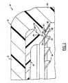
- a circumferential array of angularly spaced air vent openingsextend through lip 24. These air vent openings preferably are in the form of slots or channels 44 that open at the radially inner edge of lip 24, and at the upper and lower surfaces of lip 24. Channels 44 have a radially inwardly facing surface 46 at an angle to the axis of the closure skirt.
- Surface 46is a compound surface in the illustrated embodiment, having a first portion 48 adjacent to skirt 22 at a first angle to the skirt axis, and a second portion 50 that extends to lip surface 40 at a second greater angle to the skirt axis.
- the angle of surface portion 50controls the depth of the vent and the vent air flow rate.
- the angle of surface portion 48is for tool design purposes, and could be the same as the angle of portion 50.
- Surface portion 48 in the exemplary embodiment of the inventionis at an angle of 15.5° to the closure axis, while surface portion 50 is at an angle of 27.5°.
- the upper end of surface 40preferably is at the inside surface of closure skirt 22, while the lower surface of surface 50 preferably is at the juncture of lip surface portions 40 and 42.
- vent channels 44there are twelve vent channels 44 equally spaced around lip 24, with each channel being about 0.635 mm (0.025 inch) wide. Air vent channels 44 preferably are molded into lip 24 during injection or compression molding of the closure shell. As an alternative, vent channels 44 can be scored or otherwise formed in lip 24 in a post-molding operation.
- FIG. 5is a schematic illustration of tooling 60 for compression molding liner 18 within shell 16.
- Such toolingpreferably includes a liner tip 62 that is slidably mounted within a sleeve assembly 64.
- Sleeve assembly 64preferably includes an inner sleeve 66 and an outer sleeve 68 that, together with tip 62 and closure shell 16, form a cavity 70 for compression molding liner 18.
- An air vent passage 72is provided between sleeves 66,68.
- the lower face of sleeve 68engages lip surface portion 40 and the radially inner edge of lip 24 to close cavity 70.
- Vent channels 44 in lip 24open to the lower face of sleeve 68.
Landscapes
- Engineering & Computer Science (AREA)
- Mechanical Engineering (AREA)
- Closures For Containers (AREA)
Abstract
Description
- The present invention relates to compression molding sealing liners within closure shells, and more particularly to venting the compression mold cavity to prevent formation of bubbles in the liner.
- Plastic closures for many types of beverage, food, juice, pharmaceutical and like applications include a plastic shell that has a lip extending radially inwardly from the closure skirt at a position adjacent to but spaced from the inside surface of the closure shell base wall. A sealing liner is compression molded in situ on the inside surface of the closure base wall, with the lip cooperating with compression mold tooling to form the mold cavity.
U.S. Patents 4,984,703 and6,660,349 illustrate closures of this type. It has been proposed to provide vent passages in the liner compression mold tooling to vent air from the mold cavity as the liner is being molded. However, passages in the liner compression mold tooling can become clogged or obstructed, preventing proper ventilation of the mold cavity and leading to entrapment of air bubbles in the liner. This, in turn, undesirably increases the production scrap rate and therefore the cost of producing the closures. It is a general object of the present invention to provide a closure in which the liner compression mold cavity is vented through the closure shell rather than through the mold tooling, thereby enhancing the venting of air from the mold cavity, reducing or eliminating entrapment of air bubbles in the liners, and reducing the closure scrap rate and the cost of production. European Patent ApplicationEP 0 073 334 A discloses a closure shell corresponding to the preamble of claim 1. - A closure shell in accordance with one aspect of the invention includes abase wall with a skirt for securement to a container finish, a lip that extends radially inwardly from the skirt at a position adjacent to but spaced from the base wall, and at least one passage that extends through the lip. In the preferred embodiment of the invention, the passage is in the form of a channel that opens at a radially inner edge of the lip and at axially spaced surfaces of the lip. The channel preferably has a radially inwardly facing surface that angles axially away from the base wall and radially inwardly from the skirt. The lip preferably has a surface that faces axially away from the base wall, with at least a portion adjacent to a radially inner edge of the lip that is flat and perpendicular to the axis of the skirt. The channel preferably opens at this flat portion of the axially facing lip surface.
- A plastic closure in accordance with another aspect of the presently preferred embodiment of the invention includes a shell having a base wall with a skirt for securement to a container finish and a lip that extends radially inwardly from the skirt at a position adjacent to and spaced from the base wall. A liner is compression molded in situ against the base wall, and between the base wall and the lip. The lip has a plurality of circumferentially spaced passages that extend through the lip for venting air during compression molding of the liner.
- The invention also comprises a method of making a closure as defined by claim 9.
- The invention, together with additional objects, features, advantages and aspects thereof, will best be understood from the following description, the appended claims and the accompanying drawings, in which:
FIG. 1 is a perspective view of a package that includes a container and a closure in accordance with one presently preferred embodiment of the invention;FIG. 2 is a fragmentary sectional view of the closure in the package ofFIG. 1 ;FIG. 3 is a partially sectioned elevational view of the as-molded closure shell in the closure ofFIGS. 1 and2 ;FIG. 4 is a fragmentary sectional view taken substantially along the line 4-4 inFIG. 3 ; andFIG. 5 is a fragmentary schematic diagram that illustrates tooling for compression molding a liner in the closure shell ofFIGS. 3-4 .FIG. 1 illustrates a package 10 as comprising acontainer 12 of glass or plastic construction and aplastic closure 14 secured to the finish ofcontainer 12. Closure 14 preferably is secured tocontainer 12 by means of one or more internal threads (or thread segments) onclosure 14 in engagement with one or more external threads (or thread segments) on the finish ofcontainer 12.FIG. 2 illustratesplastic closure 14 in accordance with one presently preferred embodiment of the invention as comprising a plastic cap orshell 16 and aplastic liner 18 compression molded in situ withinshell 16.Shell 16 includes abase wall 20 and aperipheral skirt 22 having one or more internal threads (or thread segments) 23 (FiG. 3 ) for securing the closure to the finish of container 12 (FIG. 1 ). A circumferentially continuousannular lip 24 integrally extends radially inwardly fromskirt 22 adjacent to but axially spaced frombase wall 20.Lip 24 has an interior surface 26 - i.e., a facing the opposing interior surface of base wall 20 - disposed at an acute angle tobase wall 20. Specifically, in the preferred embodiment,surface 26 includes a first conical surface portion 28 adjacent toskirt 22 at a first acute angle tobase wall 20, and a secondconical surface portion 30 extending from surface portion 28 at a second acute angle tobase wall 20. Anedge 32 forms athird surface 34 at a third acute angle to the base wall.Lip 24 has asurface 38 that faces axially away frombase wall 20. Thissurface 38 preferably includes afirst portion 40 adjacent to the radially inner edge oflip 24 that is flat and perpendicular to the axis of closure skirt 22 (i.e. - perpendicular within the tolerances of the shell mold tooling), and a second radiallyouter portion 42 that is at an angle to the axis of the closure skirt. In one exemplary embodiment of the invention for a 38mm finish, surface portion 28 is at an angle of 45°,surface portion 30 is at an angle of 10°,surface portion 34 is at an angle of 72° and surface portion is 42 is at an angle of 60°, all with respect to the central axis ofskirt 22.- A circumferential array of angularly spaced air vent openings extend through
lip 24. These air vent openings preferably are in the form of slots orchannels 44 that open at the radially inner edge oflip 24, and at the upper and lower surfaces oflip 24.Channels 44 have a radially inwardly facingsurface 46 at an angle to the axis of the closure skirt.Surface 46 is a compound surface in the illustrated embodiment, having afirst portion 48 adjacent toskirt 22 at a first angle to the skirt axis, and asecond portion 50 that extends tolip surface 40 at a second greater angle to the skirt axis. The angle ofsurface portion 50 controls the depth of the vent and the vent air flow rate. The angle ofsurface portion 48 is for tool design purposes, and could be the same as the angle ofportion 50.Surface portion 48 in the exemplary embodiment of the invention is at an angle of 15.5° to the closure axis, whilesurface portion 50 is at an angle of 27.5°. The upper end ofsurface 40 preferably is at the inside surface ofclosure skirt 22, while the lower surface ofsurface 50 preferably is at the juncture oflip surface portions FIGS. 2-4 . Directional words such as "axial" and "radial" are employed by way of description and not limitation with respect to the central axis ofclosure skirt 22 All exemplary dimensions and angles are nominal.) In the exemplary embodiment of the invention, there are twelvevent channels 44 equally spaced aroundlip 24, with each channel being about 0.635 mm (0.025 inch) wide.Air vent channels 44 preferably are molded intolip 24 during injection or compression molding of the closure shell. As an alternative,vent channels 44 can be scored or otherwise formed inlip 24 in a post-molding operation. Sealing liner 18 is compression molded in situ againstbase wall 20, and betweenbase wall 20 andlip 24.Liner 18 may be of any suitable construction, such as disclosed for example in any one ofU.S. Patents 4,984,703 ,5,306,542 ,6,371,318 ,6,399,170 and6,660,349 .FIG. 5 is a schematic illustration oftooling 60 forcompression molding liner 18 withinshell 16. Such tooling preferably includes aliner tip 62 that is slidably mounted within asleeve assembly 64.Sleeve assembly 64 preferably includes aninner sleeve 66 and anouter sleeve 68 that, together withtip 62 andclosure shell 16, form acavity 70 forcompression molding liner 18. Anair vent passage 72 is provided betweensleeves FIG. 5 ) engageslip surface portion 40 and the radially inner edge oflip 24 to closecavity 70.Vent channels 44 inlip 24 open to the lower face ofsleeve 68. During molding ofliner 18, a charge of liner material is placed withinshell 16 withmold tooling 60 retracted. The mold tooling is then moved into the shell, withsleeves FIG. 5 .Liner tip 62 is then moved further into the shell to compress the charge of liner material and cause the liner material to flow outwardly toward the periphery ofcavity 70. The air displaced by this material flow can vent throughchannels 44 and radially outwardly aroundsleeve 68 so as to prevent entrapment of the air as pockets or bubbles within the liner.- There thus have been disclosed a closure shell, a plastic closure, and a method of making a plastic shell and closure that fully satisfy all of the objects and aim previously set forth. The invention has been disclosed in conjunction with a presently preferred embodiment thereof, and a number of modifications and variations have been discussed. Other modifications and variations will readily suggest themselves to persons of ordinary skill in the art in view of the foregoing description. For example, the principles of the present invention are illustrated in conjunction with a cold soft drink closure having vent slots in the threads and a tamper band at the edge of the skirt; however, the invention is by no means limited to closures of this type. The invention is intended to embrace all such modifications and variations as fall within the appended claims.
Claims (13)
- A closure shell (16) that includes a base wall (20) with a skirt (22) for securement to a container finish and a lip (24) that extends radially inwardly from said skirt at a position adjacent to and spaced from said base wall,
characterized in that at least one passage (44) extends through said lip. - The closure shell set forth in claim 1 wherein said at least one passage (44) includes a plurality of circumferentially spaced passages.
- The closure shell set forth in claim 1 wherein said at least one passage (44) includes at least one channel that opens at a radially inner edge of said lip and at axially spaced surfaces of said lip.
- The closure shell set forth in claim 3 wherein said at least one channel has a radially inwardly facing surface (46) that angles axially away from said base wall and radially inwardly from said skirt.
- The closure shell set forth in claim 4 wherein said lip (24) has a surface (38) that faces axially away from said base wall with at least a portion (40) adjacent to a radially inner edge of said lip that is flat and perpendicular to an axis of said skirt, and wherein said at least one channel opens at said flat portion of said axially facing surface.
- The closure shell set forth in claim 4 or 5 wherein said at least one channel has a radially inner end that opens at said flat portion of said axially facing surface and a radially outer end that opens at a radially inner surface of said skirt.
- The closure shell set forth in claim 4, 5 or 6 wherein in said at least one channel includes a plurality of circumferentially spaced channels.
- A plastic closure comprising a closure shell as set forth in any preceding claim, and a liner (18) compression molded in situ against said base wall, and between said base wall and said lip, said passage (44) venting air during compression molding of said liner.
- A method of making a closure that includes the steps of:(a) providing a shell (16) having a base wall (20) with a skirt (22) for securement to a container finish and a lip (24) that extends radially inwardly from said skirt at a position adjacent to and spaced from said base wall,(b) compression molding a sealing liner (18) against said base wall, and between said base wall and said lip, by (b1) placing linermaterial within said shell, (b2) engaging said lip with a sleeve (68) to form a mold cavity, and (b3) engaging the liner material with a tip (64) to force the liner material radially outwardly within said cavity beneath said sleeve and beneath said lip, and(c) providing a plurality of vent openings (44) in said lip so that air within said cavity can escape through said vent openings beneath said sleeve.
- The method set forth in claim 9 wherein said vent openings (44) comprise channels that open at a radially inner edge of said lip and at axially spaced surfaces of said lip.
- The method set forth in claim 10 wherein each of said channels has a radially inwardly facing surface (46) that angles axially away from said base wall and radially inwardly from said skirt.
- the method set forth in claim 11 wherein said lip (24) has a surface (38) that faces axially away from said base wall with at least a portion (40) adjacent to a radially inner edge of said lip that is flat and perpendicular to an axis of said skirt, wherein said channels open at said flat portion of said axially facing surface, and wherein said sleeve (68) engages said axially facing flat surface in said step (b2).
- The method set forth in claim 10, 11 or 12 wherein said channels have radially outer ends that open at a radially inner surface of said skirt.
Applications Claiming Priority (2)
| Application Number | Priority Date | Filing Date | Title |
|---|---|---|---|
| US10/917,070US7867425B2 (en) | 2004-08-11 | 2004-08-11 | Closure with liner seal vents |
| PCT/US2005/025051WO2006019949A1 (en) | 2004-08-11 | 2005-07-14 | Closure with liner seal vents |
Publications (2)
| Publication Number | Publication Date |
|---|---|
| EP1781548A1 EP1781548A1 (en) | 2007-05-09 |
| EP1781548B1true EP1781548B1 (en) | 2008-10-29 |
Family
ID=35134367
Family Applications (1)
| Application Number | Title | Priority Date | Filing Date |
|---|---|---|---|
| EP05771025AExpired - LifetimeEP1781548B1 (en) | 2004-08-11 | 2005-07-14 | Closure with liner seal vents |
Country Status (11)
| Country | Link |
|---|---|
| US (3) | US7867425B2 (en) |
| EP (1) | EP1781548B1 (en) |
| CN (1) | CN101001788B (en) |
| AT (1) | ATE412584T1 (en) |
| AU (1) | AU2005275107A1 (en) |
| BR (1) | BRPI0514215A (en) |
| DE (1) | DE602005010717D1 (en) |
| ES (1) | ES2314687T3 (en) |
| RU (1) | RU2361793C2 (en) |
| WO (1) | WO2006019949A1 (en) |
| ZA (1) | ZA200701658B (en) |
Cited By (4)
| Publication number | Priority date | Publication date | Assignee | Title |
|---|---|---|---|---|
| USD633386S1 (en) | 2010-05-27 | 2011-03-01 | Silgan White Cap LLC | Closure |
| USD634200S1 (en) | 2010-05-27 | 2011-03-15 | Silgan White Cap LLC | Closure |
| USD634199S1 (en) | 2010-05-27 | 2011-03-15 | Silgan White Cap LLC | Closure |
| US8231020B2 (en) | 2010-05-27 | 2012-07-31 | Silgan White Cap LLC | Impact resistant closure |
Families Citing this family (23)
| Publication number | Priority date | Publication date | Assignee | Title |
|---|---|---|---|---|
| US7867425B2 (en) | 2004-08-11 | 2011-01-11 | Rexam Closure Systems Inc. | Closure with liner seal vents |
| CA2711072A1 (en)* | 2008-01-11 | 2009-07-16 | Ball Corporation | Method and apparatus for providing a positive pressure in the headspace of a plastic container |
| WO2011106586A1 (en)* | 2010-02-26 | 2011-09-01 | Closure Systems International, Inc. | Method of forming a composite closure |
| US8763830B2 (en)* | 2010-10-15 | 2014-07-01 | Closure Systems International Inc. | Tamper-evident closure having tamper-indicating pilfer band with projections and package including the tamper-evident closure |
| KR101430794B1 (en) | 2011-10-18 | 2014-08-14 | 정명철 | Medal-type double-type closure for double opening |
| US12263994B2 (en) | 2012-11-01 | 2025-04-01 | Niagara Bottling, Llc | Extended thread tamper band evidence |
| USD723919S1 (en)* | 2013-10-24 | 2015-03-10 | Silgan White Cap LLC | Closure |
| WO2015123666A1 (en) | 2014-02-14 | 2015-08-20 | Closure Systems International Inc. | Improved tamper-evident closure |
| US10196189B2 (en) | 2015-10-16 | 2019-02-05 | Zipz, Inc. | Carbonated beverage closure |
| BR112018015742A2 (en)* | 2016-02-02 | 2019-01-08 | Clarke Hanan Jay | tamper evidence bridges |
| US11214410B2 (en)* | 2016-02-02 | 2022-01-04 | Niagara Bottling, Llc | Tamper evidence container closure |
| US10308400B2 (en)* | 2017-07-07 | 2019-06-04 | Closure Systems International Inc. | Closure for a package |
| US11097872B2 (en)* | 2017-12-29 | 2021-08-24 | Altria Client Services Llc | Composite lid of container and method of attaching metal lid to plastic lid to form composite lid of container |
| WO2019199657A1 (en)* | 2018-04-09 | 2019-10-17 | Berry Global, Inc. | Closure |
| AU2019312561B2 (en) | 2018-07-30 | 2025-05-29 | Niagara Bottling, Llc | Container preform with threaded tamper evidence finish |
| US11597556B2 (en) | 2018-07-30 | 2023-03-07 | Niagara Bottling, Llc | Container preform with tamper evidence finish portion |
| CR20220114A (en) | 2019-10-07 | 2022-05-23 | Closure Systems Int Inc | Flip-top closure |
| US12280921B2 (en)* | 2020-08-20 | 2025-04-22 | Sidel Participations Sas | Hinged closure |
| USD1063612S1 (en) | 2020-09-28 | 2025-02-25 | Closure Systems International Inc. | Closure with tamper-evident band |
| USD1063613S1 (en) | 2020-09-28 | 2025-02-25 | Closure Systems International Inc. | Closure with tamper-evident band |
| USD996967S1 (en) | 2021-05-17 | 2023-08-29 | Closure Systems International Inc. | Closure |
| USD996968S1 (en) | 2021-05-17 | 2023-08-29 | Closure Systems International Inc. | Closure |
| WO2024207097A1 (en) | 2023-04-05 | 2024-10-10 | Husky Injection Molding Systems Ltd. | Closures with tamper evidence |
Family Cites Families (44)
| Publication number | Priority date | Publication date | Assignee | Title |
|---|---|---|---|---|
| US4349116A (en)* | 1978-12-07 | 1982-09-14 | Ethyl Products Company | Thermoplastic screw-threaded closure cap |
| US4497765A (en)* | 1979-09-21 | 1985-02-05 | H-C Industries, Inc. | Process for making a closure |
| US4407422A (en)* | 1981-06-04 | 1983-10-04 | H-C Industries, Inc. | Composite closure |
| AU560751B2 (en) | 1981-07-24 | 1987-04-16 | H-C Industries Inc. | Plastic bottle closure |
| US4418828A (en)* | 1981-07-24 | 1983-12-06 | H-C Industries, Inc. | Plastic closure with mechanical pilfer band |
| US4381840A (en)* | 1981-08-24 | 1983-05-03 | Ethyl Products Company | Threaded closure with free-floating liner |
| US4664280A (en)* | 1985-04-16 | 1987-05-12 | H-C Industries, Inc. | Composite closure |
| GB2181119A (en) | 1985-10-08 | 1987-04-15 | Grace W R & Co | Plastic container closure with moulded liner |
| US4651886A (en)* | 1986-07-14 | 1987-03-24 | Gene Stull | Screw cap with sealing liner |
| US4721221A (en)* | 1987-01-20 | 1988-01-26 | Owens-Illinois Closure Inc. | Molded plastic closure with sealing liner |
| US4801030A (en)* | 1987-05-28 | 1989-01-31 | Owens-Illinois Closure Inc. | Tamper-indicating closure and package |
| GB8918550D0 (en)* | 1989-08-15 | 1989-09-27 | Lawson Mardon M I Ltd | Composite cap assembly and mould therefor |
| US5009324A (en)* | 1989-09-01 | 1991-04-23 | Anchor Hocking Corporation | Closure having thermally responsive water washing slots |
| US4984703A (en) | 1989-10-03 | 1991-01-15 | Owens-Illinois Closure Inc. | Plastic closure with compression molded sealing liner |
| US5064084A (en)* | 1990-08-27 | 1991-11-12 | H-C Industries, Inc. | Composite closure with seal proportioning lip |
| JP3124570B2 (en) | 1991-02-28 | 2001-01-15 | アジレント・テクノロジー株式会社 | Mixer circuit |
| JPH04339772A (en)* | 1991-05-09 | 1992-11-26 | Toyo Seikan Kaisha Ltd | Container lid with liner and production thereof |
| US5488888A (en)* | 1993-04-19 | 1996-02-06 | Owens-Illinois Closure Inc. | Method of forming bridges in tamper indicating closures |
| ES2119132T3 (en)* | 1993-12-23 | 1998-10-01 | Crown Cork Ag | SYNTHETIC MATERIAL CLOSING CAP WITH INTERIOR SEAL WITH EARLY VENTILATION. |
| US5579936A (en)* | 1994-10-31 | 1996-12-03 | The Clorox Company | Reverse channel bi-directional venting liner |
| US5730306A (en)* | 1994-03-31 | 1998-03-24 | The Clorox Company | Bi-directional venting liner |
| JP3302178B2 (en) | 1994-06-22 | 2002-07-15 | 日本クラウンコルク株式会社 | Synthetic resin container lid |
| EP0746509A1 (en) | 1994-12-29 | 1996-12-11 | Alcoa Closure Systems International, Inc. | Container closure having an improved sealing liner |
| IT239014Y1 (en) | 1995-10-24 | 2001-02-19 | Sacmi | SCREW CAPS IN PLASTIC MATERIAL FOR CLOSING CONTAINERS |
| US5800764A (en)* | 1995-12-26 | 1998-09-01 | Alcoa Closure Systems International, Inc. | External venting method for forming closure liners |
| RU2091282C1 (en)* | 1996-09-06 | 1997-09-27 | Закрытое акционерное общество "НИТЭК" | Sealing screw cap |
| JP2001520968A (en)* | 1997-10-25 | 2001-11-06 | セイフティー キャップ システム アクチエンゲゼルシャフト | Plastic screw cap for sealing bottles or the like |
| US5884790A (en)* | 1997-10-30 | 1999-03-23 | Crown Cork & Seal Technologies Corporation | Closure cap with braking structure |
| EP0987190A1 (en) | 1998-09-14 | 2000-03-22 | Crown Cork & Seal Technologies Corporation | Closure cap |
| US6382444B1 (en)* | 1999-03-17 | 2002-05-07 | Sentinel Packaging Systems, Inc. | Tamper-evident plastic closure system with snap-on band |
| US6202872B1 (en)* | 1999-10-01 | 2001-03-20 | Alcoa Closure Systems International | Composite closure with enhanced sealing |
| AUPQ365899A0 (en)* | 1999-10-26 | 1999-11-18 | Amcor Packaging (Australia) Pty Ltd | A tamper evident closure |
| JP2002069424A (en)* | 2000-08-31 | 2002-03-08 | Masao Sumita | Organic hybrid damping material, method for producing the same, and damping improver used therefor |
| WO2002024542A2 (en)* | 2000-09-20 | 2002-03-28 | Alcoa Closure Systems International, Inc. | Venting plastic closure |
| US6660349B1 (en)* | 2000-09-29 | 2003-12-09 | Owens-Illinois Closure Inc. | Plastic closure with compression molded layered barrier liner |
| US6702133B1 (en)* | 2000-10-12 | 2004-03-09 | Crown Cork & Seal Technologies Corporation | Plastic retorable container system having a closure with an improved conformable liner |
| US6474515B1 (en)* | 2000-11-10 | 2002-11-05 | The Coca-Cola Company | Vented closure |
| WO2002090192A2 (en)* | 2001-05-04 | 2002-11-14 | Berry Plastics Corporation | Beverage container closure |
| JP2003261155A (en)* | 2002-03-04 | 2003-09-16 | Alcoa Closure Systems Japan Ltd | Synthetic resin cap |
| US8517194B2 (en)* | 2004-03-11 | 2013-08-27 | Berry Plastics Corporation | Tamper-indicating closure and package |
| US7306108B2 (en)* | 2004-04-13 | 2007-12-11 | Berry Plastics Corporation | Closure with vents for venting during molding of a liner, method of forming a liner in a closure, and device for forming a liner in a closure |
| US20050284837A1 (en)* | 2004-06-18 | 2005-12-29 | James Taber | Composite closure with barrier end panel |
| US7867425B2 (en) | 2004-08-11 | 2011-01-11 | Rexam Closure Systems Inc. | Closure with liner seal vents |
| ES2385673T3 (en)* | 2005-12-28 | 2012-07-30 | Silgan White Cap LLC | Plastic closure cap with sealing gasket |
- 2004
- 2004-08-11USUS10/917,070patent/US7867425B2/enactiveActive
- 2005
- 2005-07-14ATAT05771025Tpatent/ATE412584T1/ennot_activeIP Right Cessation
- 2005-07-14ZAZA200701658Apatent/ZA200701658B/enunknown
- 2005-07-14AUAU2005275107Apatent/AU2005275107A1/ennot_activeAbandoned
- 2005-07-14WOPCT/US2005/025051patent/WO2006019949A1/enactiveApplication Filing
- 2005-07-14RURU2007108774/12Apatent/RU2361793C2/ennot_activeIP Right Cessation
- 2005-07-14CNCN2005800272359Apatent/CN101001788B/ennot_activeExpired - Fee Related
- 2005-07-14DEDE602005010717Tpatent/DE602005010717D1/ennot_activeExpired - Lifetime
- 2005-07-14EPEP05771025Apatent/EP1781548B1/ennot_activeExpired - Lifetime
- 2005-07-14ESES05771025Tpatent/ES2314687T3/ennot_activeExpired - Lifetime
- 2005-07-14BRBRPI0514215-6Apatent/BRPI0514215A/enactiveSearch and Examination
- 2010
- 2010-11-30USUS12/956,817patent/US8328038B2/ennot_activeExpired - Fee Related
- 2012
- 2012-08-10USUS13/571,520patent/US8794461B2/ennot_activeExpired - Fee Related
Cited By (5)
| Publication number | Priority date | Publication date | Assignee | Title |
|---|---|---|---|---|
| USD633386S1 (en) | 2010-05-27 | 2011-03-01 | Silgan White Cap LLC | Closure |
| USD634200S1 (en) | 2010-05-27 | 2011-03-15 | Silgan White Cap LLC | Closure |
| USD634199S1 (en) | 2010-05-27 | 2011-03-15 | Silgan White Cap LLC | Closure |
| US8231020B2 (en) | 2010-05-27 | 2012-07-31 | Silgan White Cap LLC | Impact resistant closure |
| US8672158B2 (en) | 2010-05-27 | 2014-03-18 | Silgan White Cap LLC | Impact resistant closure |
Also Published As
| Publication number | Publication date |
|---|---|
| RU2361793C2 (en) | 2009-07-20 |
| ES2314687T3 (en) | 2009-03-16 |
| RU2007108774A (en) | 2008-09-20 |
| US20060032831A1 (en) | 2006-02-16 |
| AU2005275107A1 (en) | 2006-02-23 |
| BRPI0514215A (en) | 2008-06-03 |
| US20120298670A1 (en) | 2012-11-29 |
| CN101001788B (en) | 2010-09-29 |
| US20110068104A1 (en) | 2011-03-24 |
| US8794461B2 (en) | 2014-08-05 |
| US7867425B2 (en) | 2011-01-11 |
| US8328038B2 (en) | 2012-12-11 |
| EP1781548A1 (en) | 2007-05-09 |
| CN101001788A (en) | 2007-07-18 |
| WO2006019949A1 (en) | 2006-02-23 |
| ATE412584T1 (en) | 2008-11-15 |
| ZA200701658B (en) | 2008-10-29 |
| DE602005010717D1 (en) | 2008-12-11 |
Similar Documents
| Publication | Publication Date | Title |
|---|---|---|
| EP1781548B1 (en) | Closure with liner seal vents | |
| EP0844972B1 (en) | Composite closure and method of making same | |
| US7611026B1 (en) | Tamper-evident closure having a sealing disk and package for high-temperature applications | |
| US20080272514A1 (en) | Closure Cap With Injection Molded Annular Gasket and Method of Making Same | |
| US6152316A (en) | Tamper-indicating closure and method of manufacture | |
| CA2409916C (en) | Tamper-indicating closure, container, package and methods of manufacture | |
| WO1996027532A9 (en) | Composite closure and method of making same | |
| CA2248818A1 (en) | Preform and closure for blow molded articles | |
| US7306108B2 (en) | Closure with vents for venting during molding of a liner, method of forming a liner in a closure, and device for forming a liner in a closure | |
| US6854614B2 (en) | Closure having an improved thread design | |
| CN1082424C (en) | Efficient Manufacturing Method for Plastic Assemblies | |
| US6977104B1 (en) | Container preform assembly and method of manufacture | |
| US20060278601A1 (en) | Plastic closure, closure and container package, and method of manufacture | |
| MXPA01002269A (en) | Method for producing a closing cap and closing cap produced according to said method. | |
| US20050142311A1 (en) | Finish assembly for a plastic container or preform | |
| EP2539137B1 (en) | Method of forming a composite closure | |
| EP3253548A1 (en) | An injection moulding method of forming a closure | |
| US20060073293A1 (en) | Finish assembly, preform assembly, container assembly, and method of manufacture |
Legal Events
| Date | Code | Title | Description |
|---|---|---|---|
| PUAI | Public reference made under article 153(3) epc to a published international application that has entered the european phase | Free format text:ORIGINAL CODE: 0009012 | |
| 17P | Request for examination filed | Effective date:20070201 | |
| AK | Designated contracting states | Kind code of ref document:A1 Designated state(s):AT BE BG CH CY CZ DE DK EE ES FI FR GB GR HU IE IS IT LI LT LU LV MC NL PL PT RO SE SI SK TR | |
| DAX | Request for extension of the european patent (deleted) | ||
| GRAP | Despatch of communication of intention to grant a patent | Free format text:ORIGINAL CODE: EPIDOSNIGR1 | |
| RAP1 | Party data changed (applicant data changed or rights of an application transferred) | Owner name:REXAM CLOSURE SYSTEMS INC. | |
| GRAS | Grant fee paid | Free format text:ORIGINAL CODE: EPIDOSNIGR3 | |
| RAP1 | Party data changed (applicant data changed or rights of an application transferred) | Owner name:REXAM CLOSURE SYSTEMS INC. | |
| GRAA | (expected) grant | Free format text:ORIGINAL CODE: 0009210 | |
| AK | Designated contracting states | Kind code of ref document:B1 Designated state(s):AT BE BG CH CY CZ DE DK EE ES FI FR GB GR HU IE IS IT LI LT LU LV MC NL PL PT RO SE SI SK TR | |
| REG | Reference to a national code | Ref country code:GB Ref legal event code:FG4D | |
| REG | Reference to a national code | Ref country code:CH Ref legal event code:EP | |
| REG | Reference to a national code | Ref country code:IE Ref legal event code:FG4D | |
| REF | Corresponds to: | Ref document number:602005010717 Country of ref document:DE Date of ref document:20081211 Kind code of ref document:P | |
| REG | Reference to a national code | Ref country code:ES Ref legal event code:FG2A Ref document number:2314687 Country of ref document:ES Kind code of ref document:T3 | |
| NLV1 | Nl: lapsed or annulled due to failure to fulfill the requirements of art. 29p and 29m of the patents act | ||
| LTIE | Lt: invalidation of european patent or patent extension | Effective date:20081029 | |
| PG25 | Lapsed in a contracting state [announced via postgrant information from national office to epo] | Ref country code:LT Free format text:LAPSE BECAUSE OF FAILURE TO SUBMIT A TRANSLATION OF THE DESCRIPTION OR TO PAY THE FEE WITHIN THE PRESCRIBED TIME-LIMIT Effective date:20081029 Ref country code:BG Free format text:LAPSE BECAUSE OF FAILURE TO SUBMIT A TRANSLATION OF THE DESCRIPTION OR TO PAY THE FEE WITHIN THE PRESCRIBED TIME-LIMIT Effective date:20090129 Ref country code:AT Free format text:LAPSE BECAUSE OF FAILURE TO SUBMIT A TRANSLATION OF THE DESCRIPTION OR TO PAY THE FEE WITHIN THE PRESCRIBED TIME-LIMIT Effective date:20081029 | |
| PG25 | Lapsed in a contracting state [announced via postgrant information from national office to epo] | Ref country code:NL Free format text:LAPSE BECAUSE OF FAILURE TO SUBMIT A TRANSLATION OF THE DESCRIPTION OR TO PAY THE FEE WITHIN THE PRESCRIBED TIME-LIMIT Effective date:20081029 Ref country code:SI Free format text:LAPSE BECAUSE OF FAILURE TO SUBMIT A TRANSLATION OF THE DESCRIPTION OR TO PAY THE FEE WITHIN THE PRESCRIBED TIME-LIMIT Effective date:20081029 Ref country code:PT Free format text:LAPSE BECAUSE OF FAILURE TO SUBMIT A TRANSLATION OF THE DESCRIPTION OR TO PAY THE FEE WITHIN THE PRESCRIBED TIME-LIMIT Effective date:20090330 Ref country code:PL Free format text:LAPSE BECAUSE OF FAILURE TO SUBMIT A TRANSLATION OF THE DESCRIPTION OR TO PAY THE FEE WITHIN THE PRESCRIBED TIME-LIMIT Effective date:20081029 Ref country code:IS Free format text:LAPSE BECAUSE OF FAILURE TO SUBMIT A TRANSLATION OF THE DESCRIPTION OR TO PAY THE FEE WITHIN THE PRESCRIBED TIME-LIMIT Effective date:20090228 Ref country code:FI Free format text:LAPSE BECAUSE OF FAILURE TO SUBMIT A TRANSLATION OF THE DESCRIPTION OR TO PAY THE FEE WITHIN THE PRESCRIBED TIME-LIMIT Effective date:20081029 Ref country code:LV Free format text:LAPSE BECAUSE OF FAILURE TO SUBMIT A TRANSLATION OF THE DESCRIPTION OR TO PAY THE FEE WITHIN THE PRESCRIBED TIME-LIMIT Effective date:20081029 | |
| PG25 | Lapsed in a contracting state [announced via postgrant information from national office to epo] | Ref country code:EE Free format text:LAPSE BECAUSE OF FAILURE TO SUBMIT A TRANSLATION OF THE DESCRIPTION OR TO PAY THE FEE WITHIN THE PRESCRIBED TIME-LIMIT Effective date:20081029 Ref country code:BE Free format text:LAPSE BECAUSE OF FAILURE TO SUBMIT A TRANSLATION OF THE DESCRIPTION OR TO PAY THE FEE WITHIN THE PRESCRIBED TIME-LIMIT Effective date:20081029 Ref country code:RO Free format text:LAPSE BECAUSE OF FAILURE TO SUBMIT A TRANSLATION OF THE DESCRIPTION OR TO PAY THE FEE WITHIN THE PRESCRIBED TIME-LIMIT Effective date:20081029 Ref country code:DK Free format text:LAPSE BECAUSE OF FAILURE TO SUBMIT A TRANSLATION OF THE DESCRIPTION OR TO PAY THE FEE WITHIN THE PRESCRIBED TIME-LIMIT Effective date:20081029 | |
| PG25 | Lapsed in a contracting state [announced via postgrant information from national office to epo] | Ref country code:SE Free format text:LAPSE BECAUSE OF FAILURE TO SUBMIT A TRANSLATION OF THE DESCRIPTION OR TO PAY THE FEE WITHIN THE PRESCRIBED TIME-LIMIT Effective date:20090129 Ref country code:CZ Free format text:LAPSE BECAUSE OF FAILURE TO SUBMIT A TRANSLATION OF THE DESCRIPTION OR TO PAY THE FEE WITHIN THE PRESCRIBED TIME-LIMIT Effective date:20081029 | |
| PLBE | No opposition filed within time limit | Free format text:ORIGINAL CODE: 0009261 | |
| STAA | Information on the status of an ep patent application or granted ep patent | Free format text:STATUS: NO OPPOSITION FILED WITHIN TIME LIMIT | |
| PG25 | Lapsed in a contracting state [announced via postgrant information from national office to epo] | Ref country code:SK Free format text:LAPSE BECAUSE OF FAILURE TO SUBMIT A TRANSLATION OF THE DESCRIPTION OR TO PAY THE FEE WITHIN THE PRESCRIBED TIME-LIMIT Effective date:20081029 | |
| 26N | No opposition filed | Effective date:20090730 | |
| PG25 | Lapsed in a contracting state [announced via postgrant information from national office to epo] | Ref country code:MC Free format text:LAPSE BECAUSE OF NON-PAYMENT OF DUE FEES Effective date:20090731 | |
| REG | Reference to a national code | Ref country code:CH Ref legal event code:PL | |
| PG25 | Lapsed in a contracting state [announced via postgrant information from national office to epo] | Ref country code:LI Free format text:LAPSE BECAUSE OF NON-PAYMENT OF DUE FEES Effective date:20090731 Ref country code:CH Free format text:LAPSE BECAUSE OF NON-PAYMENT OF DUE FEES Effective date:20090731 | |
| PG25 | Lapsed in a contracting state [announced via postgrant information from national office to epo] | Ref country code:IE Free format text:LAPSE BECAUSE OF NON-PAYMENT OF DUE FEES Effective date:20090714 | |
| PG25 | Lapsed in a contracting state [announced via postgrant information from national office to epo] | Ref country code:GR Free format text:LAPSE BECAUSE OF FAILURE TO SUBMIT A TRANSLATION OF THE DESCRIPTION OR TO PAY THE FEE WITHIN THE PRESCRIBED TIME-LIMIT Effective date:20090130 | |
| PGFP | Annual fee paid to national office [announced via postgrant information from national office to epo] | Ref country code:ES Payment date:20100813 Year of fee payment:6 | |
| PGFP | Annual fee paid to national office [announced via postgrant information from national office to epo] | Ref country code:IT Payment date:20100722 Year of fee payment:6 | |
| PG25 | Lapsed in a contracting state [announced via postgrant information from national office to epo] | Ref country code:LU Free format text:LAPSE BECAUSE OF NON-PAYMENT OF DUE FEES Effective date:20090714 | |
| PG25 | Lapsed in a contracting state [announced via postgrant information from national office to epo] | Ref country code:HU Free format text:LAPSE BECAUSE OF FAILURE TO SUBMIT A TRANSLATION OF THE DESCRIPTION OR TO PAY THE FEE WITHIN THE PRESCRIBED TIME-LIMIT Effective date:20090430 | |
| PG25 | Lapsed in a contracting state [announced via postgrant information from national office to epo] | Ref country code:TR Free format text:LAPSE BECAUSE OF FAILURE TO SUBMIT A TRANSLATION OF THE DESCRIPTION OR TO PAY THE FEE WITHIN THE PRESCRIBED TIME-LIMIT Effective date:20081029 | |
| PG25 | Lapsed in a contracting state [announced via postgrant information from national office to epo] | Ref country code:CY Free format text:LAPSE BECAUSE OF FAILURE TO SUBMIT A TRANSLATION OF THE DESCRIPTION OR TO PAY THE FEE WITHIN THE PRESCRIBED TIME-LIMIT Effective date:20081029 | |
| PGFP | Annual fee paid to national office [announced via postgrant information from national office to epo] | Ref country code:FR Payment date:20110805 Year of fee payment:7 | |
| PGFP | Annual fee paid to national office [announced via postgrant information from national office to epo] | Ref country code:GB Payment date:20110725 Year of fee payment:7 Ref country code:DE Payment date:20110727 Year of fee payment:7 | |
| PG25 | Lapsed in a contracting state [announced via postgrant information from national office to epo] | Ref country code:IT Free format text:LAPSE BECAUSE OF NON-PAYMENT OF DUE FEES Effective date:20110714 | |
| GBPC | Gb: european patent ceased through non-payment of renewal fee | Effective date:20120714 | |
| REG | Reference to a national code | Ref country code:ES Ref legal event code:FD2A Effective date:20130417 | |
| REG | Reference to a national code | Ref country code:FR Ref legal event code:ST Effective date:20130329 | |
| PG25 | Lapsed in a contracting state [announced via postgrant information from national office to epo] | Ref country code:DE Free format text:LAPSE BECAUSE OF NON-PAYMENT OF DUE FEES Effective date:20130201 Ref country code:GB Free format text:LAPSE BECAUSE OF NON-PAYMENT OF DUE FEES Effective date:20120714 Ref country code:FR Free format text:LAPSE BECAUSE OF NON-PAYMENT OF DUE FEES Effective date:20120731 Ref country code:ES Free format text:LAPSE BECAUSE OF NON-PAYMENT OF DUE FEES Effective date:20110715 | |
| REG | Reference to a national code | Ref country code:DE Ref legal event code:R119 Ref document number:602005010717 Country of ref document:DE Effective date:20130201 |