EP1779813B1 - Orthopaedic implant systems with anti-abrasion studs - Google Patents
Orthopaedic implant systems with anti-abrasion studsDownload PDFInfo
- Publication number
- EP1779813B1 EP1779813B1EP06255177AEP06255177AEP1779813B1EP 1779813 B1EP1779813 B1EP 1779813B1EP 06255177 AEP06255177 AEP 06255177AEP 06255177 AEP06255177 AEP 06255177AEP 1779813 B1EP1779813 B1EP 1779813B1
- Authority
- EP
- European Patent Office
- Prior art keywords
- stud
- component
- head
- abrasion
- bearing surface
- Prior art date
- Legal status (The legal status is an assumption and is not a legal conclusion. Google has not performed a legal analysis and makes no representation as to the accuracy of the status listed.)
- Active
Links
Images


Classifications
- A—HUMAN NECESSITIES
- A61—MEDICAL OR VETERINARY SCIENCE; HYGIENE
- A61F—FILTERS IMPLANTABLE INTO BLOOD VESSELS; PROSTHESES; DEVICES PROVIDING PATENCY TO, OR PREVENTING COLLAPSING OF, TUBULAR STRUCTURES OF THE BODY, e.g. STENTS; ORTHOPAEDIC, NURSING OR CONTRACEPTIVE DEVICES; FOMENTATION; TREATMENT OR PROTECTION OF EYES OR EARS; BANDAGES, DRESSINGS OR ABSORBENT PADS; FIRST-AID KITS
- A61F2/00—Filters implantable into blood vessels; Prostheses, i.e. artificial substitutes or replacements for parts of the body; Appliances for connecting them with the body; Devices providing patency to, or preventing collapsing of, tubular structures of the body, e.g. stents
- A61F2/02—Prostheses implantable into the body
- A61F2/30—Joints
- A61F2/38—Joints for elbows or knees
- A61F2/3859—Femoral components
- A—HUMAN NECESSITIES
- A61—MEDICAL OR VETERINARY SCIENCE; HYGIENE
- A61F—FILTERS IMPLANTABLE INTO BLOOD VESSELS; PROSTHESES; DEVICES PROVIDING PATENCY TO, OR PREVENTING COLLAPSING OF, TUBULAR STRUCTURES OF THE BODY, e.g. STENTS; ORTHOPAEDIC, NURSING OR CONTRACEPTIVE DEVICES; FOMENTATION; TREATMENT OR PROTECTION OF EYES OR EARS; BANDAGES, DRESSINGS OR ABSORBENT PADS; FIRST-AID KITS
- A61F2/00—Filters implantable into blood vessels; Prostheses, i.e. artificial substitutes or replacements for parts of the body; Appliances for connecting them with the body; Devices providing patency to, or preventing collapsing of, tubular structures of the body, e.g. stents
- A61F2/02—Prostheses implantable into the body
- A61F2/30—Joints
- A61F2/38—Joints for elbows or knees
- A61F2/3877—Patellae or trochleae
- A—HUMAN NECESSITIES
- A61—MEDICAL OR VETERINARY SCIENCE; HYGIENE
- A61F—FILTERS IMPLANTABLE INTO BLOOD VESSELS; PROSTHESES; DEVICES PROVIDING PATENCY TO, OR PREVENTING COLLAPSING OF, TUBULAR STRUCTURES OF THE BODY, e.g. STENTS; ORTHOPAEDIC, NURSING OR CONTRACEPTIVE DEVICES; FOMENTATION; TREATMENT OR PROTECTION OF EYES OR EARS; BANDAGES, DRESSINGS OR ABSORBENT PADS; FIRST-AID KITS
- A61F2/00—Filters implantable into blood vessels; Prostheses, i.e. artificial substitutes or replacements for parts of the body; Appliances for connecting them with the body; Devices providing patency to, or preventing collapsing of, tubular structures of the body, e.g. stents
- A61F2/02—Prostheses implantable into the body
- A61F2/30—Joints
- A61F2/38—Joints for elbows or knees
- A61F2002/3895—Joints for elbows or knees unicompartimental
Definitions
- This inventionrelates generally to prostheses for human body joints, and more particularly, to prostheses for human knees.
- a prosthetic replacement of the damaged jointmay be necessary to relieve pain and to restore normal use to the joint.
- the entire jointis replaced by means of a surgical procedure that involves removal of the ends of the corresponding damaged bones and replacement of these ends with prosthetic implants.
- This replacement of a native joint with a prosthetic jointis referred to as a primary total-joint arthroplasty.
- Prosthetic components for use in replacing the distal femurare shaped to replace the articulating surfaces (shown at 21, 23 in FIG. 1 ) of the medial condyle (shown at 20 in FIG. 1 ), lateral condyle (shown at 22 in FIG. 1 ) and trochlea, and prosthetic components for use in replacing the proximal tibia are shaped to replace the tibial plateau.
- the tibial componentis two piece: one piece is affixed to the bone and the other piece is a bearing with concave surfaces receiving the femoral condyles.
- a portion of the patellais also replaced with a prosthetic component as part of the total knee replacement.
- the medial or lateral compartment of the kneemay be replaced with uni-condylar components that replace the articulating surface of one condyle of the distal femur and one side of the tibial plateau.
- the patellofemoral compartmentmay be replaced with a femoral component that replaces a portion of the trochlea and a patellar component that replaces part of the patella.
- two or three unicompartmental componentsare implanted together in one joint; for example, two sets of uni-condylar components could be implanted together to replace the articulating surfaces of both the medial and lateral sides of the tibio-femoral joint, a trochlear component (and patellar component) and a set of uni-condylar femoral and tibial components could be implanted together, or two sets of uni-condylar components and a trochlear component (and patellar component) could be implanted together.
- patellofemoral implant componentsinclude those sold under the trade marks LCS UNI, Preservation and LCS PFJ by DePuy Orthopaedics Inc, Patella MOD III and Patella II by Smith & Nephew Richards Inc) and Oxford by Biomet Inc.
- FIG.illustrates an example of a human femur 10 with an implanted trochlear implant component 11.
- the areas of exposed native tissueinclude the intercondylar notch 16, and areas 18, 19 of the distal femoral condyles 20, 22 adjacent to the intercondylar notch 16 and an area 24 of the distal femoral condyles 20, 22 lying between the distal portion 27 of the trochlear component 11 and the anterior portion 29 of the uni-condylar femoral component 13.
- the distal portion 27 of the trochlear component 11generally tapers toward its distal end which is positioned near or within the intercondylar notch 16.
- FIG. 3illustrates the femur 10 of FIG. 2 , shown with a patellar implant component 31 engaging the trochlear component 11.
- the patellar component 31includes a bearing surface 33 that bears against a bearing surface 35 of the patellar component 11.
- the exposed bearing surface 35 of the illustrated trochlear implant component 11has two convex surfaces 39, 41 meeting along a groove 43.
- FIG. 4illustrates the femur of FIG. 3 with the patellar component 31 positioned with respect to the trochlear component 11 as it would be with the knee in deep flexion. When the knee is in deep flexion, a portion of the patellar component 31 may extend beyond the edges of the distal portion 27 of the trochlear component 11.
- Such an overhanging portion (shown at 37 in FIG. 4 ) of the patellar component 31may contact and rub against the patient's native tissue (such as native tissue indicated at 18, 19 and 24 in FIG. 4 ) as the knee flexes and extends.
- This contactmay result in painful irritation of the native tissue.
- This painful irritationcould be prevented through use of a total knee prosthesis; however, use of a total knee prosthesis could result in an unnecessary loss of healthy bone tissue.
- the pain resulting from this irritationcould be treated by revising the surgery, replacing the uni-compartmental components 11, 13 with a total knee prosthesis, again resulting in the loss of healthy bone tissue.
- US-A-2005/0177242which is regardes as the closest prior art, discloses a trochlear component with an intercondylar notch portion with tapered wings extending distally and curved posteriorly.
- the wingsalso curve away from each other in the posterior direction.
- the wingsprovide additional bearing surfaces for the patellar implant component, they may not cover the portions of the femur that potentially contact the patellar prosthesis bearing surface.
- individual patient anatomiesmay prevent use of such a trochlear implant in all patients.
- the present inventionprovides an implant system that protects a patient's native tissue when the patient has been treated with uni-compartmental or multi-compartmental arthroplasty.
- the protection offered by the present inventioncan be provided in a wide range of patient anatomies.
- the inventionprovides an orthopaedic implant system that includes, in addition to uni-compartmental implant components, one or more anti-abrasion studs that extend the bearing areas of other implant components to protect native tissue from damage resulting from engaging a patellar implant component during flexion and extension.
- the orthopaedic implant system of the present inventionmay include a trochlear implant component, a patellar implant component, one or more uni-condylar femoral implant components, and one or more uni-condylar tibial implant components against which the uni-condylar femoral components articulate.
- the present inventionprovides this protection and wide range of use by providing a knee implant system according to claim 1.
- FIG. 5shows the distal end of a human femur 10, shown with two compartments of the distal femur 10 replaced by a trochlear implant component and a uni-condylar femoral implant component.
- the illustrated trochlear and uni-condylar implant components of FIG 5are similar to those disclosed in US-A-2005/ 0154471 .
- the present inventionis not limited to the structures disclosed in that document; the principles of the present invention, and the addition of anti-abrasion studs 50, can be broadly applied to other implant systems wherein a portion of native tissue is exposed to potential contact with the articulating surface.
- the illustrated trochlear implant component 12is sized and shaped to replace a portion of the patellofemoral compartment of the distal femur without covering the distal articulating surfaces 21, 23 of the medial and lateral condyles 20, 22.
- the trochlear component 12has an exposed bearing surface 34 and a bone-facing surface underlying the bearing surface.
- the exposed bearing surface 34 of the illustrated trochlear implant component 12has two convex surfaces 38, 40 meeting along a groove 42.
- the illustrated trochlear implant component 12is sized and shaped to provide an articulating surface for the patellar component 30, so that the patellar component 30 engages the trochlear component 12 when the leg is in extension as well as through a normal range of flexion.
- the illustrated uni-condylar implant component 14is sized and shaped to replace the femoral condyle surface 21 that articulates with the proximal tibia.
- the uni-condylar femoral implant component 14has an exposed arcuate articulating or bearing surface 44 and an underlying bone-facing surface.
- the bone-facing surfacecan be porous to promote bone ingrowth, or can be adapted for cemented fixation.
- the illustrated uni-condylar femoral implant component 14is sized and shaped to cover the distal and posterior articulating surfaces of one femoral condyle.
- the illustrated trochlear component 12has a distal portion 26 that tapers distally and posteriorly; the illustrated uni-condylar femoral component 14 has an anterior portion 28 that tapers proximally and anteriorly.
- One end of the illustrated trochlear component 12is implanted adjacent to the intercondylar notch 16.
- the intercondylar notch 16remains in its native state, as does a portion 24 of the femoral condyle between the tapering edges of the trochlear component 12 and the uni-condylar femoral component 14 and as do portions 18, 19 of the distal femur adjacent to the intercondylar notch 16.
- These portions 18, 19, 24 of the femur in their native stateinclude native tissue, such as articular cartilage.
- uni-condylar femoral implant component 14would be used in conjunction with a uni-condylar tibial implant component.
- a uni-condylar tibial implant componentwould typically be two-piece, with a metal base and a polymer bearing made of a material such as ultra-high molecular weight polyethylene (UHMWPE), but could be a single integral implant component made out of a material such as UHMWPE.
- UHMWPEultra-high molecular weight polyethylene
- the implant systemwould also typically include a patellar implant component, such as that shown at 30 in FIGS. 3-4 .
- the patellar implant component 30is sized and shaped to replace a posterior portion of the patella.
- the patellar implant componenthas a bearing surface 32 and a bone-facing surface.
- the illustrated patellar implant component 30is a two-piece component, with a bearing made out of a smooth material such as (UHMWPE), although the patellar component could be a single integral implant component made out of a material such as UHMWPE.
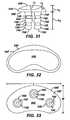
- the orthopaedic implant system of FIG. 5includes a first embodiment of an anti-abrasion stud 50A implanted at this area 24 of native tissue.
- the orthopaedic implant system of FIG. 6includes a medial anti-abrasion stud 50B and a lateral anti-abrasion stud 50C implanted at these areas 18, 19.
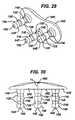
- other embodiments 50D, 50E of anti-abrasion studsmay also be employed to extend the patellar tracking surface and thereby protect native tissue.
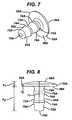
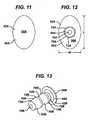
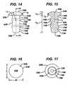
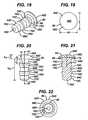
- All of the illustrated anti-abrasion studs 50A, 50B, 50C, 50D, 50Einclude common features. As shown in FIGS. 7-33 , they each include a head 52A, 52B, 52C, 52D, 52E and a fixation post 54A, 54B, 54C, 54D, 54E. Each head 52A, 52B, 52C, 52D, 52E has a bearing surface 56A, 56B, 56C, 56D, 56E and an opposite bone-facing surface 58A, 58B, 58C, 58D, 58E.
- fixation posts 54A, 54B, 54C, 54D, 54Eextend outward from the bone-facing surface 58A, 58B, 58C, 58D, 58E of the head 52A, 52B, 52C, 52D, 52E.
- each of the illustrated anti-abrasion stud 50A, 50B, 50C, 50D, 50Eis sized and shaped to fit between a portion of the trochlear component 12 and a portion of one uni-condylar femoral implant component 14 without contacting either the trochlear component or the uni-condylar femoral implant component when all of the components are implanted on the distal femur, as illustrated in FIGS. 5 and 6 . As can also be seen from FIGS.
- the head 52A, 52B, 52C, 52D, 52E of each anti-abrasion stud 50A, 50B, 50C, 50D, 50Ehas a shape that is different from the shape of the bearing surfaces of the trochlear implant component 12 and the uni-condylar femoral implant component 14.
- Two of the illustrated anti-abrasion studs 50A, 50Dhave heads that are elliptical in top plan view (see FIGS. 11 and 27 ); two of the illustrated anti-abrasion studs 50B, 50C have heads that are circular in top plan view (see FIGS. 16 and 19 ); and one of the illustrated anti-abrasion studs 50E has a head that is kidney-shaped in top plan view (see FIG. 32 ).
- the heads of the anti-abrasion studsare provided as examples only. Alternative shapes may be used and are within the scope of the invention.
- the heads of the anti-abrasions studscan have an edge that is shaped to complement the shape of a portion of the edge of the trochlear implant component.
- the head 52A, 52B, 52C, 52D, 52E of each of the illustrated anti-abrasion studs 50A, 50B, 50C, 50D, 50Ehas a height between the lowest portion of the bone-facing surface 58A, 58B, 58C, 58D, 58E and the highest point on the bearing surface 56A, 56B, 56C, 56D, 56E. These heights are indicated at "h 1 " in FIGS. 8 , 10 , 15 , 20 , 25 , 26 and 31 . Generally, head heights h, are at least about 2 mm. The head heights h, are not more than about 6 mm.
- FIG. 34illustrates the lowermost point of the bone-facing surface 54A of one of the anti-abrasion studs 50A positioned against the bone surface 51, with a substantial part of the bearing surface 56A of the head 52A above the top level of the articular cartilage 53 surrounding the anti-abrasion stud 50A.
- a portion of another implant component, such as trochlear component 12is shown in cross-section in FIG. 34 . Examples of numerical values for h 1 for the illustrated embodiments are provided in Table 1, below.
- the head 52A, 52B, 52C, 52D, 52E of each of the illustrated anti-abrasion studs 50A, 50B, 50C, 50D and 50Ehas a maximum length and width. These lengths and widths are indicated at "L” and "w” in FIGS. 12 , 16 , 19 , 27 and 33 . Examples of numerical values for 1 and w for the illustrated embodiments are provided in Table 1, below. Examples of numerical values for the perimeters of the illustrated heads are also provided in Table 1 below.
- All of the bearing surfaces 56A, 56B, 56C, 56D, 56E of the illustrated anti-abrasion studs 50A, 50B, 50C, 50D, 50Eare contoured and substantially smooth, to provide a low friction path for the patellar component during flexion and extension.
- the illustrated bearing surfacesare convex.
- the radii of curvature for the bearing surfacesare indicated at "r 1 " in FIGS. 8 , 15 , 21 , 24 , 26 and 30 . Examples of numerical values for r 1 for the illustrated embodiments are provided in Table 1, below.
- Examples of surface areas for the bearing surfaces of the illustrated headsare also provided in Table 1 below.
- the profiles of the bearing surfaces 56A, 56B, 56C, 56D, 56E of the illustrated embodimentsare provided as examples only.
- Various profiles for the bearing surfacescould be used; the most appropriate profile for a bearing surface may relate to the shape of the bearing surface of the implant that the anti-abrasion stud is augmenting or extending.
- a particular profile or groups of profiles for the bearing surfaces of the anti-abrasion studscan be selected to best augment a wide variety of main implant shapes and sizes. For example, it may be desirable to include a concave portion to form a track. Accordingly, the present invention is not limited to any particular profile for the bearing surfaces of the anti-abrasion studs unless expressly called for in the claims.
- the head 52A, 52B, 52C, 52D, 52E of each of the illustrated anti-abrasion studs 50A, 50B, 50C, 50D, 50Ehas a curved edge 60A, 60B, 60C, 60D, 60E around the perimeter of the bearing surface.
- the curved edges 60A, 60B, 60C, 60D, 60Eextend toward the bone-facing surfaces 58A, 58B, 58C, 58D, 58E.
- the curved edgeshave radii of curvature of at least about 0.5 mm.
- the radii of curvature of the curved edgesare not more than about 5mm. These radii are indicated at "r 2 " in FIGS.
- Table 1Stud ref Dimension (mm) Surface area (mm 2 ) L w h 1 h 2 r 1 r 2 Perimeter 50A 18 12 2.34 12.66 30 0.5 142.44 183.66 50B 10 10 2.34 12.66 10 1 87.27 99.00 50C 10 10 2.34 12.66 10 1 87.27 99.00 50D 20 14 3.75 11.26 30 2 165.85 288.32 50E 41 22 5.00 13.50 30 5 365.10 857.98
- fixation posts 54A, 54B, 54C, 54D, 54E of each of the illustrated embodiments of anti-abrasion studs 50A, 50B, 50C, 50D, 50Eare provided for affixation of the studs to the patient's bone.
- the illustrated fixation postsare intended to be placed in a prepared bore in the patient's bone, such as the substantially cylindrical bore shown at 57 in FIG. 34 , and include raised surface features to aid in affixation of the posts to the walls of the bore 57 in the bone.
- Each of the illustrated fixation posts 54A, 54B, 54C, 54D, 54Ehas a flat, circular end 70A, 70B, 70C, 70D, 70E opposite the head 52A, 52B, 52C, 52D, 52E.
- the illustrated fixation postsinclude a plurality of spaced cylindrical portions 72A, 72B, 72C, 72D, 72E having a first diameter and spaced raised cylindrical portions 74A, 74B, 74C, 74D, 74E having a second larger diameter.
- the cylindrical portions 72A, 72B, 72C, 72D, 72E and raised cylindrical portions 74A, 74B, 74C, 74D, 74Eare concentric about the longitudinal axes 75A, 75B, 75C, 75D, 75E of the fixation posts.
- the fixation postsfurther include conical bevelled portions 76A, 76B, 76C, 76D connecting the raised cylindrical portions 74A, 74B, 74C, and 74D to the cylindrical portions 72A, 72B, 72C, and 72D.
- the conical bevelled portions 76A, 76B, 76C, 76Dare concentric about the longitudinal axes 75A, 75B, 75C, 75D of the fixation posts and taper toward the flat circular ends 70A, 70B, 70C, and 70D of the fixation posts.
- fixation posts and the positions of the fixation posts relative to the headsmay vary depending on the size and shape of the head.
- the longitudinal axes of the fixation posts 54A, 54B, 54C, 54Dare aligned with the centres of the heads 52A, 52B, 52C, 52D.
- fixation posts 54A, 54B, 54C, 54D, 54E and their surface features 70, 72, 74are provided in Table 2.
- Table 2Stud ref Diameter (mm) Circular end 70 Smaller diameter cylindrical portion 72 Larger diameter cylindrical portion 74 50A 2 5 6 50B 2 5 6 50C 2 5 6 50D 2 5 6 50E 2 4 5
- surface features 70, 72, 74 described aboveare provided as examples only. Other surface features to aid in fixation of the anti-abrasion studs in the bone could be used in addition to or in place of the surface features illustrated and described above. For example, longitudinal surface features could be employed; grooves, ridges or fins could also be used to enhance fixation and retard rotation of the anti-abrasion studs.
- the entire head 52A, 52B, 52D and 52E and fixation post 54A, 54B, 54D, 54Eare integrally-formed.
- the anti-abrasion studscould be made as multi-piece implants that can be assembled in the operating room.
- the anti-abrasion stud 50C of FIGS. 18-22is an example of a two-piece anti-abrasion stud, wherein the fixation post 54C includes a flange 80 to which an independent bearing 82 is affixed. Together, the flange 80 and bearing 82 form the head 52C of the stud 50C.
- the bearing 82can be affixed to the flange 80 in any standard manner, such as through an interference fir or frictional lock.
- a surgical kitcould be modular, including a plurality of bearings 82 of different sizes and shapes from which the surgeon may select the most appropriate size and shape for the particular patient.
- the anti-abrasion studs 50A, 50B, 50C, 50D, 50E of the present inventionmay be made of any standard bio-compatible material, although it is preferred that the material be one that is not biodegradable and not bioresorbable. Common metal alloys, such as standard medical implant grade cobalt-chrome alloys and titanium alloys, may be used for the entire implant.
- the fixation post 54C and flange 80may be made of such a standard material, and the bearing 82 may be made of a different material, such as a ceramic or polymer (for example, ultra-high molecular weight polyethylene), if desired.
- the entire anti-abrasion studcould also be made of such a ceramic or polymer.
- all or part of the anti-abrasion studis made of a metal alloy, it may be desirable for the surfaces that will contact bone to be treated to be conducive to bone ingrowth.
- standard industrycan be employed to make the bone-contacting surfaces porous. Coatings may also be employed to induce bone ingrowth into the appropriate portions of the stud or to deliver drugs to the site.
- the bearing surfaces 56A, 56B, 56C, 56D, 56E of the anti-abrasion studspreferably provide a low-friction surface for the patellar bearing to move across during the flexion and extension. If the heads 52A, 52B, 52C, 52D, 52E are made of metal, the bearing surfaces may be highly polished to maximize smooth movement of the patellar bearing across the stud bearing surface.
- the anti-abrasion studs of the present inventionmay be provided in the form of implant system, sets or kits.
- a knee implant system, set or kitcould include a set of trochlear components, patellar components and anti-abrasion studs.
- the system, set or kitcould also include uni-condylar femoral implant components and uni-condylar tibial implant components. All of the implant components could be provided in a variety of sizes to accommodate a wide range of patient anatomies.
- the anti-abrasion studs included in the system, set or kitcould include a variety of sizes of a single head shape or a variety of head shapes, profiles and sizes.
- the orthopaedic surgeonwould prepare the patient's bones in the most appropriate fashion for implantation of the first or major implant components.
- the trochlea of the distal femurwould be resected or otherwise shaped or prepared to receive the trochlear implant component and the patella would be resected or otherwise shaped or prepared to receive the patellar implant component (if a patellar implant component is to be used).
- the trochlear componentwould then be implanted in a standard manner, as would the patellar implant component, if used.
- one or both of the femoral condyleswould be resected or otherwise shaped or prepared to receive an appropriate uni-condylar femoral implant component and the corresponding side of the tibial plateau would be resected or otherwise shaped or prepared to receive an appropriate tibial implant component (or assembly of components).
- the femoral uni-condylar implant component or components and the uni-condylar tibial component or componentswould then be implanted in a standard manner.
- the surgeonmay chose to use one of the anti-abrasion studs of the system to extend the bearing surfaces of the other implant components.
- the orthopaedic surgeonmay select the most appropriate size and shape of anti-abrasion stud to extend the bearing surface or surfaces.
- the head of the anti-abrasion studis sized and shaped so that it will not contact any part of the trochlear implant component or uni-condylar femoral implant component.
- a drill or reameris then used to prepare a bore in the bone; preferably, the outer diameter of the drill or reamer is slightly less than the outer diameter of the fixation feature (such as larger diameter portion 74) of the fixation post.
- the fixation postis then introduced into the bore and pushed into the bore until the lowermost part of the head (such as the bone-facing portion) contacts the surface of the bone. At least a substantial part of the bearing surface of the head will be above the level of the articular cartilage. This procedure may be repeated with additional anti-abrasion studs as deemed necessary by the surgeon.
- the studsmay be implanted in a separate procedure on a later date. For example, if the patient has received a trochlear implant or a uni-condylar femoral implant and complains of pain or of a patellar component catching or making a noise during flexion or extension, the surgeon may opt to implant an anti-abrasion stud at that time. Due to the small size of the anti-abrasion studs, this subsequent procedure can be a minimally invasive one.
- the system of the present inventionprovides the surgeon with the opportunity to enhance and extend the bearing surfaces of standard uni-compartmental implant components to fit the needs of individual patients.
- the anti-abrasion studwill provide an additional bearing surface that substantially bridges a portion of the gap between the other implant components to provide an augmented bearing surface and covers and protects the native articular cartilage from abrasion.
Landscapes
- Health & Medical Sciences (AREA)
- Orthopedic Medicine & Surgery (AREA)
- Physical Education & Sports Medicine (AREA)
- Cardiology (AREA)
- Oral & Maxillofacial Surgery (AREA)
- Transplantation (AREA)
- Engineering & Computer Science (AREA)
- Biomedical Technology (AREA)
- Heart & Thoracic Surgery (AREA)
- Vascular Medicine (AREA)
- Life Sciences & Earth Sciences (AREA)
- Animal Behavior & Ethology (AREA)
- General Health & Medical Sciences (AREA)
- Public Health (AREA)
- Veterinary Medicine (AREA)
- Prostheses (AREA)
- Materials For Medical Uses (AREA)
Abstract
Description
- This invention relates generally to prostheses for human body joints, and more particularly, to prostheses for human knees.
- When a human skeletal joint is damaged, whether as a result of an accident or illness, a prosthetic replacement of the damaged joint may be necessary to relieve pain and to restore normal use to the joint. Typically the entire joint is replaced by means of a surgical procedure that involves removal of the ends of the corresponding damaged bones and replacement of these ends with prosthetic implants. This replacement of a native joint with a prosthetic joint is referred to as a primary total-joint arthroplasty.
- For a damaged human knee, the total knee is commonly replaced with prosthetic components shaped to replace portions of the distal femur, proximal tibia and patella. Prosthetic components for use in replacing the distal femur are shaped to replace the articulating surfaces (shown at 21, 23 in
FIG. 1 ) of the medial condyle (shown at 20 inFIG. 1 ), lateral condyle (shown at 22 inFIG. 1 ) and trochlea, and prosthetic components for use in replacing the proximal tibia are shaped to replace the tibial plateau. Commonly, the tibial component is two piece: one piece is affixed to the bone and the other piece is a bearing with concave surfaces receiving the femoral condyles. Frequently, a portion of the patella is also replaced with a prosthetic component as part of the total knee replacement. - In some patients, only a portion of the knee is damaged or injured. For such patients, individual compartments of the knee may be replaced. For example, the medial or lateral compartment of the knee may be replaced with uni-condylar components that replace the articulating surface of one condyle of the distal femur and one side of the tibial plateau. The patellofemoral compartment may be replaced with a femoral component that replaces a portion of the trochlea and a patellar component that replaces part of the patella. In some instances, two or three unicompartmental components are implanted together in one joint; for example, two sets of uni-condylar components could be implanted together to replace the articulating surfaces of both the medial and lateral sides of the tibio-femoral joint, a trochlear component (and patellar component) and a set of uni-condylar femoral and tibial components could be implanted together, or two sets of uni-condylar components and a trochlear component (and patellar component) could be implanted together. The following journal articles report, among other things: use of patellofemoral components (trochlear component and patellar component) and one or two sets of uni-condylar components,Arciero, Major and Toomey, "Patellofemoral Arthroplasty: A Three-to-Nine Year Follow-Up Study", 236 Clinical Orthopaedics and Related Research, Vol. 236, November 1, 1988, pages 60-71; and two sets of uni-condylar components,Bourne, Rorabeck, Finlay and Nott, "Kinematic I and Oxford Knee Arthroplasty: A 5-8-year Follow-up Study", The Journal of Arthroplasty, Vol. 2, No. 4, December, 1987, pages 285-291, andShoji, D'Ambrosia and Lipscomb, "Failed Polycentric Total Knee Prostheses", The Journal of Bone and Joint Surgery, Vol. 58-A, No. 6, September 1976, pages 773-777, andStockley, Douglas and Elson, "Bicondylar St. Georg Sledge Knee Arthroplasty", Clinical Orthopaedics and Related Research, No. 255, June, 1990, pages 228-234.
- Other documents which relate to uni-condylar knee implant components or patellofemoral implant components include
US-3852830 ,US-4034418 ,US-4340978 ,US-4838891 ,US-5871541 ,US-6616696 , andUS-6709460 . - Commercial uni-condylar knee implant components or patellofemoral implant components include those sold under the trade marks LCS UNI, Preservation and LCS PFJ by DePuy Orthopaedics Inc, Patella MOD III and Patella II by Smith & Nephew Richards Inc) and Oxford by Biomet Inc.
- When knees are replaced with common total joint prostheses, substantially all of the potential articulating surface of the distal femur is replaced and covered with metal; no native articular cartilage remains exposed in the potential area of articulation. In contrast, when one or more compartments of a knee are replaced with unicompartmental components, substantial areas of native cartilage are not covered by metal, and remain exposed. FIG. illustrates an example of a
human femur 10 with an implantedtrochlear implant component 11.FIG. 2 illustrates an example of ahuman femur 10 with an implantedtrochlear implant component 11 replacing the articulating surface of the trochlea together with a uni-condylarfemoral component 13 replacing the articulating surface of one of the femoral condyles. InFIG. 2 , the areas of exposed native tissue include theintercondylar notch 16, andareas femoral condyles intercondylar notch 16 and anarea 24 of the distalfemoral condyles distal portion 27 of thetrochlear component 11 and theanterior portion 29 of the uni-condylarfemoral component 13. As shown inFIGS. 1-2 , thedistal portion 27 of thetrochlear component 11 generally tapers toward its distal end which is positioned near or within theintercondylar notch 16. FIG. 3 illustrates thefemur 10 ofFIG. 2 , shown with apatellar implant component 31 engaging thetrochlear component 11. Thepatellar component 31 includes abearing surface 33 that bears against abearing surface 35 of thepatellar component 11. The exposedbearing surface 35 of the illustratedtrochlear implant component 11 has twoconvex surfaces groove 43.FIG. 4 illustrates the femur ofFIG. 3 with thepatellar component 31 positioned with respect to thetrochlear component 11 as it would be with the knee in deep flexion. When the knee is in deep flexion, a portion of thepatellar component 31 may extend beyond the edges of thedistal portion 27 of thetrochlear component 11. Such an overhanging portion (shown at 37 inFIG. 4 ) of thepatellar component 31 may contact and rub against the patient's native tissue (such as native tissue indicated at 18, 19 and 24 inFIG. 4 ) as the knee flexes and extends. This contact may result in painful irritation of the native tissue. This painful irritation could be prevented through use of a total knee prosthesis; however, use of a total knee prosthesis could result in an unnecessary loss of healthy bone tissue. The pain resulting from this irritation could be treated by revising the surgery, replacing theuni-compartmental components US-A-2005/0177242 , which is regardes as the closest prior art, discloses a trochlear component with an intercondylar notch portion with tapered wings extending distally and curved posteriorly. The wings also curve away from each other in the posterior direction. Although the wings provide additional bearing surfaces for the patellar implant component, they may not cover the portions of the femur that potentially contact the patellar prosthesis bearing surface. In addition, individual patient anatomies may prevent use of such a trochlear implant in all patients.- The present invention provides an implant system that protects a patient's native tissue when the patient has been treated with uni-compartmental or multi-compartmental arthroplasty. The protection offered by the present invention can be provided in a wide range of patient anatomies.
- Accordingly, the invention provides an orthopaedic implant system that includes, in addition to uni-compartmental implant components, one or more anti-abrasion studs that extend the bearing areas of other implant components to protect native tissue from damage resulting from engaging a patellar implant component during flexion and extension. In addition to the anti-abrasion studs, the orthopaedic implant system of the present invention may include a trochlear implant component, a patellar implant component, one or more uni-condylar femoral implant components, and one or more uni-condylar tibial implant components against which the uni-condylar femoral components articulate.
- In one aspect, the present invention provides this protection and wide range of use by providing a knee implant system according to
claim 1. - Embodiments of the invention will now be described by way of example with reference to the accompanying drawings, in which:
FIG. 1 is a perspective view of a distal femur with an implanted prior art trochlear implant component;FIG. 2 is a perspective view similar toFIG. 1 , showing the distal femur with both a prior art trochlear implant component and a prior art uni-condylar femoral implant component;FIG. 3 is a perspective view of a distal femur with both a prior art trochlear implant component and a prior art uni-condylar femoral implant component, showing a prior art patellar implant component bearing against the bearing surface of the trochlear implant component;FIG. 4 is an end view of a distal femur, illustrating a possible position of the patella and prior art patellar implant with respect to a prior art trochlear component and prior art uni-condylar femoral component, and further illustrating the potential for the patellar implant component to contact native tissue during flexion and extension of the knee;FIG. 5 is a perspective view of a distal femur, similar toFIG. 2 , but with a first embodiment of a stud implanted in the space between a trochlear component and uni-condylar implant component;FIG. 6 is a perspective view of a distal femur, similar toFIGS. 2 and5 , but with two studs of a second embodiment implanted in areas adjacent to the intercondylar notch of the femur;FIG. 7 is perspective view of a first embodiment of an anti-abrasion stud;FIG. 8 is an elevation of the anti-abrasion stud ofFIG. 7 ;FIG. 9 is a second elevation of the anti-abrasion stud ofFIGS. 7-8 ;FIG. 10 is a cross-section of the anti-abrasion stud ofFIG. 9 , taken along line 10-10 ofFIG. 9 ;FIG. 11 is a top plan view of the anti-abrasion stud ofFIGS. 7-10 ;FIG. 12 is a bottom plan view of the anti-abrasion stud ofFIGS. 7-11 ;FIG. 13 is perspective view of a second embodiment of an anti-abrasion stud;FIG. 14 is an elevation of the anti-abrasion stud ofFIG. 13 ;FIG. 15 is a cross-section of the anti-abrasion stud ofFIG. 14 , taken along line 15-15 ofFIG. 14 ;FIG. 16 is a top plan view of the anti-abrasion stud ofFIGS. 13-15 ;FIG. 17 is a bottom plan view of the anti-abrasion stud ofFIGS. 13-16 ;FIG. 18 is perspective view of a third embodiment of an anti-abrasion stud;FIG. 19 is a top plan view of the anti-abrasion stud ofFIG. 18 ;FIG. 20 is an elevation of the anti-abrasion stud ofFIGS. 18-19 ;FIG. 21 is a cross-section of the anti-abrasion stud ofFIGS. 18-20 , taken along line 21-21 ofFIG. 20 ;FIG. 22 is a bottom plan view of the anti-abrasion stud ofFIGS. 18-21 ;FIG. 23 is perspective view of a fourth embodiment of an anti-abrasion stud;FIG. 24 is an elevation of the anti-abrasion stud ofFIG. 23 ;FIG. 25 is a second elevation of the anti-abrasion stud ofFIGS. 23-24 ;FIG. 26 is a cross-section of the anti-abrasion stud ofFIGS. 23-25 , taken along line 26-26 ofFIG. 25 ;FIG. 27 is a top plan view of the anti-abrasion stud ofFIGS. 23-26 ;FIG. 28 is a bottom plan view of the anti-abrasion stud ofFIGS. 23-27 ;FIG. 29 is perspective view of a fifth embodiment of an anti-abrasion stud;FIG. 30 is an elevation of the anti-abrasion stud ofFIG. 29 ;FIG. 31 is a second elevation of the anti-abrasion stud ofFIGS. 29-30 ;FIG. 32 is a top plan view of the anti-abrasion stud ofFIGS. 29-31 ;FIG. 33 is a bottom plan view of the anti-abrasion stud ofFIGS. 29-32 ; andFIG. 34 is a cross-section of a portion of a femur and trochlear implant component, illustrating the position of the first embodiment of the anti-abrasion stud with respect to articular cartilage of the femur.- Referring to the drawings,
FIG. 5 shows the distal end of ahuman femur 10, shown with two compartments of thedistal femur 10 replaced by a trochlear implant component and a uni-condylar femoral implant component. The illustrated trochlear and uni-condylar implant components ofFIG 5 . are similar to those disclosed inUS-A-2005/ 0154471 . However, it should be understood that the present invention is not limited to the structures disclosed in that document; the principles of the present invention, and the addition of anti-abrasion studs 50, can be broadly applied to other implant systems wherein a portion of native tissue is exposed to potential contact with the articulating surface. - The illustrated
trochlear implant component 12 is sized and shaped to replace a portion of the patellofemoral compartment of the distal femur without covering the distal articulatingsurfaces lateral condyles trochlear component 12 has an exposedbearing surface 34 and a bone-facing surface underlying the bearing surface. The exposedbearing surface 34 of the illustratedtrochlear implant component 12 has twoconvex surfaces groove 42. The illustratedtrochlear implant component 12 is sized and shaped to provide an articulating surface for the patellar component 30, so that the patellar component 30 engages thetrochlear component 12 when the leg is in extension as well as through a normal range of flexion. - The illustrated
uni-condylar implant component 14 is sized and shaped to replace thefemoral condyle surface 21 that articulates with the proximal tibia. The uni-condylarfemoral implant component 14 has an exposed arcuate articulating or bearingsurface 44 and an underlying bone-facing surface. The bone-facing surface can be porous to promote bone ingrowth, or can be adapted for cemented fixation. Overall, the illustrated uni-condylarfemoral implant component 14 is sized and shaped to cover the distal and posterior articulating surfaces of one femoral condyle. - As shown in
FIGS. 4-6 , the illustratedtrochlear component 12 has adistal portion 26 that tapers distally and posteriorly; the illustrated uni-condylarfemoral component 14 has ananterior portion 28 that tapers proximally and anteriorly. One end of the illustratedtrochlear component 12 is implanted adjacent to theintercondylar notch 16. Theintercondylar notch 16 remains in its native state, as does aportion 24 of the femoral condyle between the tapering edges of thetrochlear component 12 and the uni-condylarfemoral component 14 and as doportions intercondylar notch 16. Theseportions - Although not illustrated in the accompanying drawings, it should be understood that the illustrated uni-condylar
femoral implant component 14 would be used in conjunction with a uni-condylar tibial implant component. Such a uni-condylar tibial implant component would typically be two-piece, with a metal base and a polymer bearing made of a material such as ultra-high molecular weight polyethylene (UHMWPE), but could be a single integral implant component made out of a material such as UHMWPE. - When a trochlear component is implanted, the implant system would also typically include a patellar implant component, such as that shown at 30 in
FIGS. 3-4 . The patellar implant component 30 is sized and shaped to replace a posterior portion of the patella. The patellar implant component has a bearingsurface 32 and a bone-facing surface. The illustrated patellar implant component 30 is a two-piece component, with a bearing made out of a smooth material such as (UHMWPE), although the patellar component could be a single integral implant component made out of a material such as UHMWPE. - To protect the
area 24 of native tissue between the opposed tapered edges of thedistal portion 26 of thetrochlear component 12 andanterior portion 28 of the uni-condylarfemoral component 14, the orthopaedic implant system ofFIG. 5 includes a first embodiment of ananti-abrasion stud 50A implanted at thisarea 24 of native tissue. To protect theareas intercondylar notch 16, the orthopaedic implant system ofFIG. 6 includes a medialanti-abrasion stud 50B and a lateralanti-abrasion stud 50C implanted at theseareas other embodiments - All of the illustrated
anti-abrasion studs FIGS. 7-33 , they each include ahead fixation post head bearing surface surface surface head - The
head anti-abrasion stud trochlear component 12 and a portion of one uni-condylarfemoral implant component 14 without contacting either the trochlear component or the uni-condylar femoral implant component when all of the components are implanted on the distal femur, as illustrated inFIGS. 5 and 6 . As can also be seen fromFIGS. 5-33 , thehead anti-abrasion stud trochlear implant component 12 and the uni-condylarfemoral implant component 14. Two of the illustratedanti-abrasion studs FIGS. 11 and27 ); two of the illustratedanti-abrasion studs FIGS. 16 and19 ); and one of the illustratedanti-abrasion studs 50E has a head that is kidney-shaped in top plan view (seeFIG. 32 ). - It should be appreciated that the three illustrated shapes for the heads of the anti-abrasion studs are provided as examples only. Alternative shapes may be used and are within the scope of the invention. For example, for anti-abrasion studs that are intended for use to extend the patellar tracking surface further toward the intercondylar notch, the heads of the anti-abrasions studs can have an edge that is shaped to complement the shape of a portion of the edge of the trochlear implant component.
- The
head anti-abrasion studs surface bearing surface FIGS. 8 ,10 ,15 ,20 ,25 ,26 and31 . Generally, head heights h, are at least about 2 mm. The head heights h, are not more than about 6 mm. Such head heights should be adequate to raise most of the bearing surface 56 of the head 52 above the exterior surface of the articular cartilage on the bone; in other words, the head heights are generally greater than the thickness of the articular cartilage where the anti-abrasion stud is implanted.FIG. 34 illustrates the lowermost point of the bone-facingsurface 54A of one of theanti-abrasion studs 50A positioned against thebone surface 51, with a substantial part of the bearingsurface 56A of thehead 52A above the top level of thearticular cartilage 53 surrounding theanti-abrasion stud 50A. A portion of another implant component, such astrochlear component 12, is shown in cross-section inFIG. 34 . Examples of numerical values for h1 for the illustrated embodiments are provided in Table 1, below. - The
head anti-abrasion studs FIGS. 12 ,16 ,19 ,27 and33 . Examples of numerical values for 1 and w for the illustrated embodiments are provided in Table 1, below. Examples of numerical values for the perimeters of the illustrated heads are also provided in Table 1 below. - All of the bearing surfaces 56A, 56B, 56C, 56D, 56E of the illustrated
anti-abrasion studs FIGS. 8 ,15 ,21 ,24 ,26 and30 . Examples of numerical values for r1 for the illustrated embodiments are provided in Table 1, below. Examples of surface areas for the bearing surfaces of the illustrated heads are also provided in Table 1 below. - It should be appreciated that the profiles of the bearing surfaces 56A, 56B, 56C, 56D, 56E of the illustrated embodiments are provided as examples only. Various profiles for the bearing surfaces could be used; the most appropriate profile for a bearing surface may relate to the shape of the bearing surface of the implant that the anti-abrasion stud is augmenting or extending. A particular profile or groups of profiles for the bearing surfaces of the anti-abrasion studs can be selected to best augment a wide variety of main implant shapes and sizes. For example, it may be desirable to include a concave portion to form a track. Accordingly, the present invention is not limited to any particular profile for the bearing surfaces of the anti-abrasion studs unless expressly called for in the claims.
- The
head anti-abrasion studs surfaces FIGS. 8 ,10 ,14, 15 ,20, 21 ,24 ,26 and31 . Examples of numerical values for r2 for the illustrated embodiments are provided in Table 1, below.Table 1 Stud ref Dimension (mm) Surface area (mm2) L w h1 h2 r1 r2 Perimeter 50A 18 12 2.34 12.66 30 0.5 142.44 183.66 50B 10 10 2.34 12.66 10 1 87.27 99.00 50C 10 10 2.34 12.66 10 1 87.27 99.00 50D 20 14 3.75 11.26 30 2 165.85 288.32 50E 41 22 5.00 13.50 30 5 365.10 857.98 - The fixation posts 54A, 54B, 54C, 54D, 54E of each of the illustrated embodiments of
anti-abrasion studs FIG. 34 , and include raised surface features to aid in affixation of the posts to the walls of thebore 57 in the bone. - Each of the illustrated
fixation posts circular end head cylindrical portions cylindrical portions cylindrical portions cylindrical portions longitudinal axes anti-abrasion studs FIGS. 7-23 , the fixation posts further include conicalbevelled portions cylindrical portions cylindrical portions bevelled portions longitudinal axes 75A, 75B, 75C, 75D of the fixation posts and taper toward the flat circular ends 70A, 70B, 70C, and 70D of the fixation posts. - The number of fixation posts and the positions of the fixation posts relative to the heads may vary depending on the size and shape of the head. For example, in the first four illustrated
anti-abrasion studs heads anti-abrasion stud 50E, there are three spacedfixation posts 54E positioned to support thehead 52E. - Examples of dimensions for the fixation posts 54A, 54B, 54C, 54D, 54E and their surface features 70, 72, 74 are provided in Table 2.
Table 2 Stud ref Diameter (mm) Circular end 70 Smaller diameter cylindrical portion 72 Larger diameter cylindrical portion 74 50A 2 5 6 50B 2 5 6 50C 2 5 6 50D 2 5 6 50E 2 4 5 - It should be understood that the surface features 70, 72, 74 described above are provided as examples only. Other surface features to aid in fixation of the anti-abrasion studs in the bone could be used in addition to or in place of the surface features illustrated and described above. For example, longitudinal surface features could be employed; grooves, ridges or fins could also be used to enhance fixation and retard rotation of the anti-abrasion studs.
- It should also be understood that all of the dimensions, areas and radii disclosed herein (including all those set out in Tables 1 and 2) are provided as examples only.
- In four of the illustrated
anti-abrasion studs entire head fixation post anti-abrasion stud 50C ofFIGS. 18-22 is an example of a two-piece anti-abrasion stud, wherein thefixation post 54C includes aflange 80 to which anindependent bearing 82 is affixed. Together, theflange 80 andbearing 82 form thehead 52C of thestud 50C. The bearing 82 can be affixed to theflange 80 in any standard manner, such as through an interference fir or frictional lock. With such a two-piece stud, a surgical kit could be modular, including a plurality ofbearings 82 of different sizes and shapes from which the surgeon may select the most appropriate size and shape for the particular patient. - The
anti-abrasion studs piece anti-abrasion stud 50C ofFIGS. 18-22 , thefixation post 54C andflange 80 may be made of such a standard material, and thebearing 82 may be made of a different material, such as a ceramic or polymer (for example, ultra-high molecular weight polyethylene), if desired. The entire anti-abrasion stud could also be made of such a ceramic or polymer. - If all or part of the anti-abrasion stud is made of a metal alloy, it may be desirable for the surfaces that will contact bone to be treated to be conducive to bone ingrowth. For example, standard industry can be employed to make the bone-contacting surfaces porous. Coatings may also be employed to induce bone ingrowth into the appropriate portions of the stud or to deliver drugs to the site.
- The bearing surfaces 56A, 56B, 56C, 56D, 56E of the anti-abrasion studs preferably provide a low-friction surface for the patellar bearing to move across during the flexion and extension. If the
heads - The anti-abrasion studs of the present invention may be provided in the form of implant system, sets or kits. For example, a knee implant system, set or kit could include a set of trochlear components, patellar components and anti-abrasion studs. The system, set or kit could also include uni-condylar femoral implant components and uni-condylar tibial implant components. All of the implant components could be provided in a variety of sizes to accommodate a wide range of patient anatomies. The anti-abrasion studs included in the system, set or kit could include a variety of sizes of a single head shape or a variety of head shapes, profiles and sizes.
- To use the
anti-abrasion studs - If the surgeon determines at the time of the original surgery that the patient would benefit from providing an enhanced or augmented patellar track extending further toward the intercondylar notch, or that the transition between the bearing surfaces of the trochlear component and the uni-condylar femoral component or components is uneven or overly extended, the surgeon may chose to use one of the anti-abrasion studs of the system to extend the bearing surfaces of the other implant components.
- The orthopaedic surgeon may select the most appropriate size and shape of anti-abrasion stud to extend the bearing surface or surfaces. Preferably, the head of the anti-abrasion stud is sized and shaped so that it will not contact any part of the trochlear implant component or uni-condylar femoral implant component. A drill or reamer is then used to prepare a bore in the bone; preferably, the outer diameter of the drill or reamer is slightly less than the outer diameter of the fixation feature (such as larger diameter portion 74) of the fixation post. The fixation post is then introduced into the bore and pushed into the bore until the lowermost part of the head (such as the bone-facing portion) contacts the surface of the bone. At least a substantial part of the bearing surface of the head will be above the level of the articular cartilage. This procedure may be repeated with additional anti-abrasion studs as deemed necessary by the surgeon.
- If the orthopaedic surgeon initially elects to avoid using the anti-abrasion studs, the studs may be implanted in a separate procedure on a later date. For example, if the patient has received a trochlear implant or a uni-condylar femoral implant and complains of pain or of a patellar component catching or making a noise during flexion or extension, the surgeon may opt to implant an anti-abrasion stud at that time. Due to the small size of the anti-abrasion studs, this subsequent procedure can be a minimally invasive one.
- Thus, the system of the present invention provides the surgeon with the opportunity to enhance and extend the bearing surfaces of standard uni-compartmental implant components to fit the needs of individual patients. The anti-abrasion stud will provide an additional bearing surface that substantially bridges a portion of the gap between the other implant components to provide an augmented bearing surface and covers and protects the native articular cartilage from abrasion.
Claims (10)
- An orthopaedic implant system for use in treating an orthopaedic disorder of a patello-femoral joint between the femur and the tibia and a tibio-femoral joint between the femur and the patella, the femur including native articular cartilage, the implant system comprising:a trochlear implant component sized and shaped to replace a portion of the femur without covering the distal surfaces of the medial and lateral condyles, the trochlear component having a bearing surface and a bone-facing surface;a uni-condylar implant component sized and shaped to replace a portion of one of the condyles of the distal femur, the uni-condylar implant component having a bearing surface and a bone-facing surface; anda patellar implant component sized and shaped to replace a portion of the patella, the patellar implant component having a bearing surface and a bone-facing surface;characterized in that the orthopaedic implant system further comprisesan implantable stud including a head having a bearing surface and a bone-facing surface, the implantable stud further including a fixation post extending outward from the bone-facing surface of the head, the head of the stud being sized and shaped to fit between a portion of the trochlear component and a portion of the uni-condylar implant component without contacting either the trochlear component or the uni-condylar implant component when all three components are implanted on the distal femur;wherein the bearing surface of the head has a different shape than the bearing surfaces of the trochlear implant component and the uni-condylar implant component; andwherein the bearing surface of the head is sized and shaped to limit contact between the patellar implant component and native tissue during flexion and extension of the knee joint.
- The orthopaedic implant system of claim 1 wherein the area of the bearing surface of the head of the stud is less than 900 mm2 and the bearing surface of the head of the implantable stud is convex and substantially smooth.
- The orthopaedic implant system of claim 2 wherein the area of the bearing surface of the head of the stud is not more than about 300 mm2, preferably not more than about 200 mm2, especially not more than about 100 mm2.
- The orthopaedic implant system of claim 2 wherein the area of the bearing surface of the head of the stud is at least about 90 mm2.
- The orthopaedic implant system of claim 2 wherein the bearing surface of the head of the implantable stud has a radius of curvature of at least about 10 mm.
- The orthopaedic implant system of claim 2 wherein the bearing surface of the head of the implantable stud has a radius of curvature of not more than about 30 mm.
- The orthopaedic implant system of claim 2 wherein the fixation post has a plurality of cylindrical portions having a first diameter and raised cylindrical portions having a second larger diameter.
- The orthopaedic implant system of claim 2 wherein the shape of the head when viewed in top plan view is circular or elliptical or kidney-shaped.
- The orthopaedic implant system of claim 2 further comprising a uni-condylar implant component sized and shaped to replace a portion of the distal surface of one of the condyles of the distal femur.
- The orthopaedic implant system of claim 2 wherein the fixation post of the implantable stud is porous.
Applications Claiming Priority (1)
| Application Number | Priority Date | Filing Date | Title |
|---|---|---|---|
| US11/260,386US20070100460A1 (en) | 2005-10-27 | 2005-10-27 | Orthopaedic implant systems with anti-abrasion studs |
Publications (2)
| Publication Number | Publication Date |
|---|---|
| EP1779813A1 EP1779813A1 (en) | 2007-05-02 |
| EP1779813B1true EP1779813B1 (en) | 2008-12-03 |
Family
ID=37670871
Family Applications (1)
| Application Number | Title | Priority Date | Filing Date |
|---|---|---|---|
| EP06255177AActiveEP1779813B1 (en) | 2005-10-27 | 2006-10-06 | Orthopaedic implant systems with anti-abrasion studs |
Country Status (6)
| Country | Link |
|---|---|
| US (1) | US20070100460A1 (en) |
| EP (1) | EP1779813B1 (en) |
| JP (1) | JP2007175481A (en) |
| AT (1) | ATE415913T1 (en) |
| AU (1) | AU2006233218A1 (en) |
| DE (1) | DE602006003983D1 (en) |
Families Citing this family (15)
| Publication number | Priority date | Publication date | Assignee | Title |
|---|---|---|---|---|
| US20070288021A1 (en)* | 2006-06-07 | 2007-12-13 | Howmedica Osteonics Corp. | Flexible joint implant |
| US8764841B2 (en) | 2007-03-30 | 2014-07-01 | DePuy Synthes Products, LLC | Mobile bearing assembly having a closed track |
| US8142510B2 (en) | 2007-03-30 | 2012-03-27 | Depuy Products, Inc. | Mobile bearing assembly having a non-planar interface |
| US8147557B2 (en) | 2007-03-30 | 2012-04-03 | Depuy Products, Inc. | Mobile bearing insert having offset dwell point |
| US8328874B2 (en) | 2007-03-30 | 2012-12-11 | Depuy Products, Inc. | Mobile bearing assembly |
| US8147558B2 (en) | 2007-03-30 | 2012-04-03 | Depuy Products, Inc. | Mobile bearing assembly having multiple articulation interfaces |
| CN105392450B (en) | 2013-03-15 | 2017-09-29 | 马科外科公司 | Tibial knee list condyle implant |
| US9655727B2 (en)* | 2013-12-12 | 2017-05-23 | Stryker Corporation | Extended patellofemoral |
| US9622868B2 (en) | 2014-04-28 | 2017-04-18 | Biomet Manufacturing, Llc | Convertible pre-partial knee replacement |
| US20150374503A1 (en)* | 2014-06-30 | 2015-12-31 | Bacterin International, Inc. | Implant for fusion between adjacent bone bodies |
| EP3634319B1 (en) | 2017-06-04 | 2021-04-14 | Stefan Eggli | Modular knee prosthesis |
| US10893948B2 (en) | 2017-11-02 | 2021-01-19 | Howmedica Osteonics Corp. | Rotary arc patella articulating geometry |
| CN115605166A (en)* | 2020-04-30 | 2023-01-13 | 澳大利亚机器人骨科学院有限公司(Au) | Orthopedic implant and surgical orthopedic system comprising same |
| JP2024506178A (en)* | 2021-02-05 | 2024-02-09 | オーバーチュア・リサーフェシング・インコーポレイテッド | Articular surface replacement implant system and method for osteochondral defects |
| KR102289960B1 (en)* | 2021-02-10 | 2021-08-17 | 주식회사 도이프 | Artifitial trochlera groove prostheseis for dog |
Family Cites Families (58)
| Publication number | Priority date | Publication date | Assignee | Title |
|---|---|---|---|---|
| US3715763A (en)* | 1971-04-21 | 1973-02-13 | W Link | Artificial limb for the knee joint |
| GB1360485A (en)* | 1971-04-21 | 1974-07-17 | Helfet Arthur Jacob | Replacements for bicondylar joints in natural or artificial human limbs |
| US3774244A (en)* | 1972-02-08 | 1973-11-27 | Relief Ruptured And Crippled S | Knee-joint prosthesis |
| US3806961A (en)* | 1972-02-16 | 1974-04-30 | Sulzer Ag | Phosthetic patella implant |
| US3852830A (en)* | 1973-02-15 | 1974-12-10 | Richards Mfg Co | Knee prosthesis |
| GB1462876A (en)* | 1973-05-17 | 1977-01-26 | Thackray C F Ltd | Knee arthroplasty |
| US3878566A (en)* | 1974-05-08 | 1975-04-22 | Richards Mfg Co | Patello-femoral prosthesis |
| US3953889A (en)* | 1974-10-24 | 1976-04-27 | Pertec Corporation | Electronic head adjust system for removable magnetic discs |
| CA1045752A (en)* | 1975-05-26 | 1979-01-09 | Robert W. Jackson | Prosthetic implant |
| GB1522497A (en)* | 1975-10-17 | 1978-08-23 | Dow Corning | Surgically implantable prosthetic devices |
| DE2703059C3 (en)* | 1977-01-26 | 1981-09-03 | Sanitätshaus Schütt & Grundei, Werkstätten für Orthopädie-Technik, 2400 Lübeck | Knee joint endoprosthesis |
| US4151615A (en)* | 1977-06-29 | 1979-05-01 | Hall Thomas D | Prosthetic patello-femoral joint |
| GB1600661A (en)* | 1978-02-17 | 1981-10-21 | Howmedica | Bicondylar joint prosthesis |
| US4224696A (en)* | 1978-09-08 | 1980-09-30 | Hexcel Corporation | Prosthetic knee |
| US4224697A (en)* | 1978-09-08 | 1980-09-30 | Hexcel Corporation | Constrained prosthetic knee |
| CH632923A5 (en)* | 1978-10-06 | 1982-11-15 | Sulzer Ag | Implant for partial replacement of a sliding surface of a human joint |
| US4340978A (en)* | 1979-07-02 | 1982-07-27 | Biomedical Engineering Corp. | New Jersey meniscal bearing knee replacement |
| SE450336B (en)* | 1984-11-28 | 1987-06-22 | Branemark Per Ingvar | LED PROTES FOR PERMANENT ANCHORING IN THE BONE TISSUE |
| SE468199B (en)* | 1988-04-11 | 1992-11-23 | Astra Ab | KNAELEDSPROTES |
| US5263987A (en)* | 1989-08-25 | 1993-11-23 | Shah Mrugesh K | Method and apparatus for arthroscopically replacing a bone joint |
| US5108441A (en)* | 1990-07-17 | 1992-04-28 | Mcdowell Charles L | Method of regenerating joint articular cartilage |
| US5123927A (en)* | 1990-12-05 | 1992-06-23 | University Of British Columbia | Method and apparatus for antibiotic knee prothesis |
| US5871541A (en)* | 1993-11-23 | 1999-02-16 | Plus Endoprothetik, Ag | System for producing a knee-joint endoprosthesis |
| US5769899A (en)* | 1994-08-12 | 1998-06-23 | Matrix Biotechnologies, Inc. | Cartilage repair unit |
| US5632745A (en)* | 1995-02-07 | 1997-05-27 | R&D Biologicals, Inc. | Surgical implantation of cartilage repair unit |
| US5702458A (en)* | 1994-12-09 | 1997-12-30 | New York Society For The Ruptured And Crippled Maintaining The Hospital For Special Surgery | Joint prosthesis |
| US5749874A (en)* | 1995-02-07 | 1998-05-12 | Matrix Biotechnologies, Inc. | Cartilage repair unit and method of assembling same |
| US6352558B1 (en)* | 1996-02-22 | 2002-03-05 | Ed. Geistlich Soehne Ag Fuer Chemische Industrie | Method for promoting regeneration of surface cartilage in a damage joint |
| US5759190A (en)* | 1996-08-30 | 1998-06-02 | Vts Holdings Limited | Method and kit for autologous transplantation |
| US5906596A (en)* | 1996-11-26 | 1999-05-25 | Std Manufacturing | Percutaneous access device |
| US5906577A (en)* | 1997-04-30 | 1999-05-25 | University Of Massachusetts | Device, surgical access port, and method of retracting an incision into an opening and providing a channel through the incision |
| US6440063B1 (en)* | 1997-04-30 | 2002-08-27 | University Of Massachusetts | Surgical access port and laparoscopic surgical method |
| US6123728A (en)* | 1997-09-17 | 2000-09-26 | Smith & Nephew, Inc. | Mobile bearing knee prosthesis |
| US6171340B1 (en)* | 1998-02-27 | 2001-01-09 | Mcdowell Charles L. | Method and device for regenerating cartilage in articulating joints |
| US6412936B1 (en)* | 1998-03-03 | 2002-07-02 | Canon Kabushiki Kaisha | Ink, ink set, ink cartridge, recording unit, image recording process and image recording apparatus |
| US6428577B1 (en)* | 1998-05-20 | 2002-08-06 | Smith & Nephew, Inc. | Mobile bearing knee prosthesis |
| US6660039B1 (en)* | 1998-05-20 | 2003-12-09 | Smith & Nephew, Inc. | Mobile bearing knee prosthesis |
| US6616696B1 (en)* | 1998-09-04 | 2003-09-09 | Alan C. Merchant | Modular knee replacement system |
| US6132468A (en)* | 1998-09-10 | 2000-10-17 | Mansmann; Kevin A. | Arthroscopic replacement of cartilage using flexible inflatable envelopes |
| EP1137451A4 (en)* | 1998-12-07 | 2003-05-21 | Std Mfg Inc | Implantable vascular access device |
| US6251143B1 (en)* | 1999-06-04 | 2001-06-26 | Depuy Orthopaedics, Inc. | Cartilage repair unit |
| US6702821B2 (en)* | 2000-01-14 | 2004-03-09 | The Bonutti 2003 Trust A | Instrumentation for minimally invasive joint replacement and methods for using same |
| US6342075B1 (en)* | 2000-02-18 | 2002-01-29 | Macarthur A. Creig | Prosthesis and methods for total knee arthroplasty |
| US6626945B2 (en)* | 2000-03-14 | 2003-09-30 | Chondrosite, Llc | Cartilage repair plug |
| US6712856B1 (en)* | 2000-03-17 | 2004-03-30 | Kinamed, Inc. | Custom replacement device for resurfacing a femur and method of making the same |
| US6709460B2 (en)* | 2000-03-21 | 2004-03-23 | Alan C. Merchant | Patellar bearing implant |
| US6520964B2 (en)* | 2000-05-01 | 2003-02-18 | Std Manufacturing, Inc. | System and method for joint resurface repair |
| US6679917B2 (en)* | 2000-05-01 | 2004-01-20 | Arthrosurface, Incorporated | System and method for joint resurface repair |
| US9050192B2 (en)* | 2001-02-05 | 2015-06-09 | Formae, Inc. | Cartilage repair implant with soft bearing surface and flexible anchoring device |
| US6743232B2 (en)* | 2001-02-26 | 2004-06-01 | David W. Overaker | Tissue scaffold anchor for cartilage repair |
| US6626950B2 (en)* | 2001-06-28 | 2003-09-30 | Ethicon, Inc. | Composite scaffold with post anchor for the repair and regeneration of tissue |
| AU2002313694B2 (en)* | 2001-07-16 | 2007-08-30 | Depuy Products, Inc. | Cartilage repair apparatus and method |
| US8187326B2 (en)* | 2002-05-22 | 2012-05-29 | Advanced Technologies And Regenerative Medicine, Llc. | Attachment of absorbable tissue scaffolds to fixation devices |
| CN1215156C (en)* | 2002-07-12 | 2005-08-17 | 吕新 | Color-flame candle and method for making same |
| US20040102852A1 (en)* | 2002-11-22 | 2004-05-27 | Johnson Erin M. | Modular knee prosthesis |
| US20050064042A1 (en)* | 2003-04-29 | 2005-03-24 | Musculoskeletal Transplant Foundation | Cartilage implant plug with fibrin glue and method for implantation |
| US7544209B2 (en)* | 2004-01-12 | 2009-06-09 | Lotke Paul A | Patello-femoral prosthesis |
| JP4510030B2 (en)* | 2004-01-12 | 2010-07-21 | デピュイ・プロダクツ・インコーポレイテッド | System and method for splitting and replacing a knee |
- 2005
- 2005-10-27USUS11/260,386patent/US20070100460A1/ennot_activeAbandoned
- 2006
- 2006-10-06ATAT06255177Tpatent/ATE415913T1/ennot_activeIP Right Cessation
- 2006-10-06EPEP06255177Apatent/EP1779813B1/enactiveActive
- 2006-10-06DEDE602006003983Tpatent/DE602006003983D1/enactiveActive
- 2006-10-26JPJP2006291491Apatent/JP2007175481A/enactivePending
- 2006-10-26AUAU2006233218Apatent/AU2006233218A1/ennot_activeAbandoned
Also Published As
| Publication number | Publication date |
|---|---|
| AU2006233218A1 (en) | 2007-05-17 |
| ATE415913T1 (en) | 2008-12-15 |
| JP2007175481A (en) | 2007-07-12 |
| EP1779813A1 (en) | 2007-05-02 |
| US20070100460A1 (en) | 2007-05-03 |
| DE602006003983D1 (en) | 2009-01-15 |
Similar Documents
| Publication | Publication Date | Title |
|---|---|---|
| EP1779813B1 (en) | Orthopaedic implant systems with anti-abrasion studs | |
| US12419755B2 (en) | Tibial tray with fixation features | |
| EP1955677B1 (en) | Femoral trochlea prostheses | |
| US8216319B2 (en) | Method of repairing a knee joint | |
| AU768133B2 (en) | Modular knee implant system | |
| US9642711B2 (en) | High flexion articular insert | |
| US9414926B2 (en) | Implant for restoring normal range flexion and kinematics of the knee | |
| US7520901B2 (en) | Bicompartmental implants and method of use | |
| EP1870058B1 (en) | Tibial insert | |
| US20130267959A1 (en) | Modular apparatus and method for sculpting the surface of a joint | |
| Yoshino et al. | Hy-Flex II total knee and ligament balancing system: preliminary report on concept, design, surgical technique, and short-term clinical results | |
| AU2014200110A1 (en) | High flexion articular insert | |
| HK1038493B (en) | Modular knee implant system |
Legal Events
| Date | Code | Title | Description |
|---|---|---|---|
| PUAI | Public reference made under article 153(3) epc to a published international application that has entered the european phase | Free format text:ORIGINAL CODE: 0009012 | |
| AK | Designated contracting states | Kind code of ref document:A1 Designated state(s):AT BE BG CH CY CZ DE DK EE ES FI FR GB GR HU IE IS IT LI LT LU LV MC NL PL PT RO SE SI SK TR | |
| AX | Request for extension of the european patent | Extension state:AL BA HR MK YU | |
| 17P | Request for examination filed | Effective date:20071011 | |
| AKX | Designation fees paid | Designated state(s):AT BE BG CH CY CZ DE DK EE ES FI FR GB GR HU IE IS IT LI LT LU LV MC NL PL PT RO SE SI SK TR | |
| GRAP | Despatch of communication of intention to grant a patent | Free format text:ORIGINAL CODE: EPIDOSNIGR1 | |
| GRAS | Grant fee paid | Free format text:ORIGINAL CODE: EPIDOSNIGR3 | |
| GRAA | (expected) grant | Free format text:ORIGINAL CODE: 0009210 | |
| AK | Designated contracting states | Kind code of ref document:B1 Designated state(s):AT BE BG CH CY CZ DE DK EE ES FI FR GB GR HU IE IS IT LI LT LU LV MC NL PL PT RO SE SI SK TR | |
| REG | Reference to a national code | Ref country code:GB Ref legal event code:FG4D | |
| REG | Reference to a national code | Ref country code:CH Ref legal event code:EP | |
| REG | Reference to a national code | Ref country code:CH Ref legal event code:NV Representative=s name:E. BLUM & CO. AG PATENT- UND MARKENANWAELTE VSP | |
| REG | Reference to a national code | Ref country code:IE Ref legal event code:FG4D | |
| REF | Corresponds to: | Ref document number:602006003983 Country of ref document:DE Date of ref document:20090115 Kind code of ref document:P | |
| PG25 | Lapsed in a contracting state [announced via postgrant information from national office to epo] | Ref country code:ES Free format text:LAPSE BECAUSE OF FAILURE TO SUBMIT A TRANSLATION OF THE DESCRIPTION OR TO PAY THE FEE WITHIN THE PRESCRIBED TIME-LIMIT Effective date:20090314 Ref country code:LT Free format text:LAPSE BECAUSE OF FAILURE TO SUBMIT A TRANSLATION OF THE DESCRIPTION OR TO PAY THE FEE WITHIN THE PRESCRIBED TIME-LIMIT Effective date:20081203 | |
| NLV1 | Nl: lapsed or annulled due to failure to fulfill the requirements of art. 29p and 29m of the patents act | ||
| PG25 | Lapsed in a contracting state [announced via postgrant information from national office to epo] | Ref country code:SI Free format text:LAPSE BECAUSE OF FAILURE TO SUBMIT A TRANSLATION OF THE DESCRIPTION OR TO PAY THE FEE WITHIN THE PRESCRIBED TIME-LIMIT Effective date:20081203 Ref country code:FI Free format text:LAPSE BECAUSE OF FAILURE TO SUBMIT A TRANSLATION OF THE DESCRIPTION OR TO PAY THE FEE WITHIN THE PRESCRIBED TIME-LIMIT Effective date:20081203 Ref country code:PL Free format text:LAPSE BECAUSE OF FAILURE TO SUBMIT A TRANSLATION OF THE DESCRIPTION OR TO PAY THE FEE WITHIN THE PRESCRIBED TIME-LIMIT Effective date:20081203 Ref country code:LV Free format text:LAPSE BECAUSE OF FAILURE TO SUBMIT A TRANSLATION OF THE DESCRIPTION OR TO PAY THE FEE WITHIN THE PRESCRIBED TIME-LIMIT Effective date:20081203 Ref country code:NL Free format text:LAPSE BECAUSE OF FAILURE TO SUBMIT A TRANSLATION OF THE DESCRIPTION OR TO PAY THE FEE WITHIN THE PRESCRIBED TIME-LIMIT Effective date:20081203 | |
| PG25 | Lapsed in a contracting state [announced via postgrant information from national office to epo] | Ref country code:RO Free format text:LAPSE BECAUSE OF FAILURE TO SUBMIT A TRANSLATION OF THE DESCRIPTION OR TO PAY THE FEE WITHIN THE PRESCRIBED TIME-LIMIT Effective date:20081203 Ref country code:EE Free format text:LAPSE BECAUSE OF FAILURE TO SUBMIT A TRANSLATION OF THE DESCRIPTION OR TO PAY THE FEE WITHIN THE PRESCRIBED TIME-LIMIT Effective date:20081203 Ref country code:BE Free format text:LAPSE BECAUSE OF FAILURE TO SUBMIT A TRANSLATION OF THE DESCRIPTION OR TO PAY THE FEE WITHIN THE PRESCRIBED TIME-LIMIT Effective date:20081203 Ref country code:BG Free format text:LAPSE BECAUSE OF FAILURE TO SUBMIT A TRANSLATION OF THE DESCRIPTION OR TO PAY THE FEE WITHIN THE PRESCRIBED TIME-LIMIT Effective date:20090303 | |
| PG25 | Lapsed in a contracting state [announced via postgrant information from national office to epo] | Ref country code:IS Free format text:LAPSE BECAUSE OF FAILURE TO SUBMIT A TRANSLATION OF THE DESCRIPTION OR TO PAY THE FEE WITHIN THE PRESCRIBED TIME-LIMIT Effective date:20090403 Ref country code:CZ Free format text:LAPSE BECAUSE OF FAILURE TO SUBMIT A TRANSLATION OF THE DESCRIPTION OR TO PAY THE FEE WITHIN THE PRESCRIBED TIME-LIMIT Effective date:20081203 Ref country code:SE Free format text:LAPSE BECAUSE OF FAILURE TO SUBMIT A TRANSLATION OF THE DESCRIPTION OR TO PAY THE FEE WITHIN THE PRESCRIBED TIME-LIMIT Effective date:20090303 Ref country code:PT Free format text:LAPSE BECAUSE OF FAILURE TO SUBMIT A TRANSLATION OF THE DESCRIPTION OR TO PAY THE FEE WITHIN THE PRESCRIBED TIME-LIMIT Effective date:20090504 Ref country code:AT Free format text:LAPSE BECAUSE OF FAILURE TO SUBMIT A TRANSLATION OF THE DESCRIPTION OR TO PAY THE FEE WITHIN THE PRESCRIBED TIME-LIMIT Effective date:20081203 | |
| PG25 | Lapsed in a contracting state [announced via postgrant information from national office to epo] | Ref country code:SK Free format text:LAPSE BECAUSE OF FAILURE TO SUBMIT A TRANSLATION OF THE DESCRIPTION OR TO PAY THE FEE WITHIN THE PRESCRIBED TIME-LIMIT Effective date:20081203 | |
| PLBE | No opposition filed within time limit | Free format text:ORIGINAL CODE: 0009261 | |
| STAA | Information on the status of an ep patent application or granted ep patent | Free format text:STATUS: NO OPPOSITION FILED WITHIN TIME LIMIT | |
| PG25 | Lapsed in a contracting state [announced via postgrant information from national office to epo] | Ref country code:DK Free format text:LAPSE BECAUSE OF FAILURE TO SUBMIT A TRANSLATION OF THE DESCRIPTION OR TO PAY THE FEE WITHIN THE PRESCRIBED TIME-LIMIT Effective date:20081203 | |
| 26N | No opposition filed | Effective date:20090904 | |
| PG25 | Lapsed in a contracting state [announced via postgrant information from national office to epo] | Ref country code:MC Free format text:LAPSE BECAUSE OF NON-PAYMENT OF DUE FEES Effective date:20091031 | |
| PG25 | Lapsed in a contracting state [announced via postgrant information from national office to epo] | Ref country code:GR Free format text:LAPSE BECAUSE OF FAILURE TO SUBMIT A TRANSLATION OF THE DESCRIPTION OR TO PAY THE FEE WITHIN THE PRESCRIBED TIME-LIMIT Effective date:20090304 | |
| PG25 | Lapsed in a contracting state [announced via postgrant information from national office to epo] | Ref country code:LU Free format text:LAPSE BECAUSE OF NON-PAYMENT OF DUE FEES Effective date:20091006 | |
| PG25 | Lapsed in a contracting state [announced via postgrant information from national office to epo] | Ref country code:HU Free format text:LAPSE BECAUSE OF FAILURE TO SUBMIT A TRANSLATION OF THE DESCRIPTION OR TO PAY THE FEE WITHIN THE PRESCRIBED TIME-LIMIT Effective date:20090604 | |
| PG25 | Lapsed in a contracting state [announced via postgrant information from national office to epo] | Ref country code:TR Free format text:LAPSE BECAUSE OF FAILURE TO SUBMIT A TRANSLATION OF THE DESCRIPTION OR TO PAY THE FEE WITHIN THE PRESCRIBED TIME-LIMIT Effective date:20081203 | |
| PG25 | Lapsed in a contracting state [announced via postgrant information from national office to epo] | Ref country code:CY Free format text:LAPSE BECAUSE OF FAILURE TO SUBMIT A TRANSLATION OF THE DESCRIPTION OR TO PAY THE FEE WITHIN THE PRESCRIBED TIME-LIMIT Effective date:20081203 | |
| PGFP | Annual fee paid to national office [announced via postgrant information from national office to epo] | Ref country code:IT Payment date:20121015 Year of fee payment:7 | |
| PG25 | Lapsed in a contracting state [announced via postgrant information from national office to epo] | Ref country code:IT Free format text:LAPSE BECAUSE OF NON-PAYMENT OF DUE FEES Effective date:20131006 | |
| REG | Reference to a national code | Ref country code:FR Ref legal event code:PLFP Year of fee payment:11 | |
| REG | Reference to a national code | Ref country code:FR Ref legal event code:PLFP Year of fee payment:12 | |
| REG | Reference to a national code | Ref country code:FR Ref legal event code:PLFP Year of fee payment:13 | |
| PGFP | Annual fee paid to national office [announced via postgrant information from national office to epo] | Ref country code:FR Payment date:20220908 Year of fee payment:17 | |
| PGFP | Annual fee paid to national office [announced via postgrant information from national office to epo] | Ref country code:CH Payment date:20221010 Year of fee payment:17 | |
| PGFP | Annual fee paid to national office [announced via postgrant information from national office to epo] | Ref country code:IE Payment date:20230912 Year of fee payment:18 Ref country code:GB Payment date:20230831 Year of fee payment:18 | |
| PGFP | Annual fee paid to national office [announced via postgrant information from national office to epo] | Ref country code:DE Payment date:20230830 Year of fee payment:18 | |
| REG | Reference to a national code | Ref country code:CH Ref legal event code:PL | |
| PG25 | Lapsed in a contracting state [announced via postgrant information from national office to epo] | Ref country code:CH Free format text:LAPSE BECAUSE OF NON-PAYMENT OF DUE FEES Effective date:20231031 | |
| PG25 | Lapsed in a contracting state [announced via postgrant information from national office to epo] | Ref country code:FR Free format text:LAPSE BECAUSE OF NON-PAYMENT OF DUE FEES Effective date:20231031 Ref country code:CH Free format text:LAPSE BECAUSE OF NON-PAYMENT OF DUE FEES Effective date:20231031 | |
| REG | Reference to a national code | Ref country code:DE Ref legal event code:R119 Ref document number:602006003983 Country of ref document:DE | |
| GBPC | Gb: european patent ceased through non-payment of renewal fee | Effective date:20241006 | |
| PG25 | Lapsed in a contracting state [announced via postgrant information from national office to epo] | Ref country code:DE Free format text:LAPSE BECAUSE OF NON-PAYMENT OF DUE FEES Effective date:20250501 | |
| PG25 | Lapsed in a contracting state [announced via postgrant information from national office to epo] | Ref country code:GB Free format text:LAPSE BECAUSE OF NON-PAYMENT OF DUE FEES Effective date:20241006 |