EP1776975B1 - Medication injector apparatus with drive assembly that facilitates reset - Google Patents
Medication injector apparatus with drive assembly that facilitates resetDownload PDFInfo
- Publication number
- EP1776975B1 EP1776975B1EP06126846AEP06126846AEP1776975B1EP 1776975 B1EP1776975 B1EP 1776975B1EP 06126846 AEP06126846 AEP 06126846AEP 06126846 AEP06126846 AEP 06126846AEP 1776975 B1EP1776975 B1EP 1776975B1
- Authority
- EP
- European Patent Office
- Prior art keywords
- pen
- drive
- assembly
- drive sleeve
- cartridge
- Prior art date
- Legal status (The legal status is an assumption and is not a legal conclusion. Google has not performed a legal analysis and makes no representation as to the accuracy of the status listed.)
- Expired - Lifetime
Links
Images


Classifications
- A—HUMAN NECESSITIES
- A61—MEDICAL OR VETERINARY SCIENCE; HYGIENE
- A61M—DEVICES FOR INTRODUCING MEDIA INTO, OR ONTO, THE BODY; DEVICES FOR TRANSDUCING BODY MEDIA OR FOR TAKING MEDIA FROM THE BODY; DEVICES FOR PRODUCING OR ENDING SLEEP OR STUPOR
- A61M5/00—Devices for bringing media into the body in a subcutaneous, intra-vascular or intramuscular way; Accessories therefor, e.g. filling or cleaning devices, arm-rests
- A61M5/178—Syringes
- A61M5/31—Details
- A61M5/315—Pistons; Piston-rods; Guiding, blocking or restricting the movement of the rod or piston; Appliances on the rod for facilitating dosing ; Dosing mechanisms
- A61M5/31533—Dosing mechanisms, i.e. setting a dose
- A61M5/31535—Means improving security or handling thereof, e.g. blocking means, means preventing insufficient dosing, means allowing correction of overset dose
- A—HUMAN NECESSITIES
- A61—MEDICAL OR VETERINARY SCIENCE; HYGIENE
- A61M—DEVICES FOR INTRODUCING MEDIA INTO, OR ONTO, THE BODY; DEVICES FOR TRANSDUCING BODY MEDIA OR FOR TAKING MEDIA FROM THE BODY; DEVICES FOR PRODUCING OR ENDING SLEEP OR STUPOR
- A61M5/00—Devices for bringing media into the body in a subcutaneous, intra-vascular or intramuscular way; Accessories therefor, e.g. filling or cleaning devices, arm-rests
- A61M5/178—Syringes
- A61M5/31—Details
- A61M5/315—Pistons; Piston-rods; Guiding, blocking or restricting the movement of the rod or piston; Appliances on the rod for facilitating dosing ; Dosing mechanisms
- A61M5/31533—Dosing mechanisms, i.e. setting a dose
- A61M5/31545—Setting modes for dosing
- A61M5/31548—Mechanically operated dose setting member
- A61M5/3155—Mechanically operated dose setting member by rotational movement of dose setting member, e.g. during setting or filling of a syringe
- A61M5/31551—Mechanically operated dose setting member by rotational movement of dose setting member, e.g. during setting or filling of a syringe including axial movement of dose setting member
- A—HUMAN NECESSITIES
- A61—MEDICAL OR VETERINARY SCIENCE; HYGIENE
- A61M—DEVICES FOR INTRODUCING MEDIA INTO, OR ONTO, THE BODY; DEVICES FOR TRANSDUCING BODY MEDIA OR FOR TAKING MEDIA FROM THE BODY; DEVICES FOR PRODUCING OR ENDING SLEEP OR STUPOR
- A61M5/00—Devices for bringing media into the body in a subcutaneous, intra-vascular or intramuscular way; Accessories therefor, e.g. filling or cleaning devices, arm-rests
- A61M5/178—Syringes
- A61M5/31—Details
- A61M5/315—Pistons; Piston-rods; Guiding, blocking or restricting the movement of the rod or piston; Appliances on the rod for facilitating dosing ; Dosing mechanisms
- A61M5/31565—Administration mechanisms, i.e. constructional features, modes of administering a dose
- A61M5/31566—Means improving security or handling thereof
- A—HUMAN NECESSITIES
- A61—MEDICAL OR VETERINARY SCIENCE; HYGIENE
- A61M—DEVICES FOR INTRODUCING MEDIA INTO, OR ONTO, THE BODY; DEVICES FOR TRANSDUCING BODY MEDIA OR FOR TAKING MEDIA FROM THE BODY; DEVICES FOR PRODUCING OR ENDING SLEEP OR STUPOR
- A61M5/00—Devices for bringing media into the body in a subcutaneous, intra-vascular or intramuscular way; Accessories therefor, e.g. filling or cleaning devices, arm-rests
- A61M5/178—Syringes
- A61M5/31—Details
- A61M5/315—Pistons; Piston-rods; Guiding, blocking or restricting the movement of the rod or piston; Appliances on the rod for facilitating dosing ; Dosing mechanisms
- A61M5/31565—Administration mechanisms, i.e. constructional features, modes of administering a dose
- A61M5/31576—Constructional features or modes of drive mechanisms for piston rods
- A61M5/31583—Constructional features or modes of drive mechanisms for piston rods based on rotational translation, i.e. movement of piston rod is caused by relative rotation between the user activated actuator and the piston rod
- A61M5/31585—Constructional features or modes of drive mechanisms for piston rods based on rotational translation, i.e. movement of piston rod is caused by relative rotation between the user activated actuator and the piston rod performed by axially moving actuator, e.g. an injection button
- G—PHYSICS
- G01—MEASURING; TESTING
- G01D—MEASURING NOT SPECIALLY ADAPTED FOR A SPECIFIC VARIABLE; ARRANGEMENTS FOR MEASURING TWO OR MORE VARIABLES NOT COVERED IN A SINGLE OTHER SUBCLASS; TARIFF METERING APPARATUS; MEASURING OR TESTING NOT OTHERWISE PROVIDED FOR
- G01D5/00—Mechanical means for transferring the output of a sensing member; Means for converting the output of a sensing member to another variable where the form or nature of the sensing member does not constrain the means for converting; Transducers not specially adapted for a specific variable
- G01D5/12—Mechanical means for transferring the output of a sensing member; Means for converting the output of a sensing member to another variable where the form or nature of the sensing member does not constrain the means for converting; Transducers not specially adapted for a specific variable using electric or magnetic means
- G01D5/244—Mechanical means for transferring the output of a sensing member; Means for converting the output of a sensing member to another variable where the form or nature of the sensing member does not constrain the means for converting; Transducers not specially adapted for a specific variable using electric or magnetic means influencing characteristics of pulses or pulse trains; generating pulses or pulse trains
- G01D5/249—Mechanical means for transferring the output of a sensing member; Means for converting the output of a sensing member to another variable where the form or nature of the sensing member does not constrain the means for converting; Transducers not specially adapted for a specific variable using electric or magnetic means influencing characteristics of pulses or pulse trains; generating pulses or pulse trains using pulse code
- G01D5/2497—Absolute encoders
- G—PHYSICS
- G01—MEASURING; TESTING
- G01D—MEASURING NOT SPECIALLY ADAPTED FOR A SPECIFIC VARIABLE; ARRANGEMENTS FOR MEASURING TWO OR MORE VARIABLES NOT COVERED IN A SINGLE OTHER SUBCLASS; TARIFF METERING APPARATUS; MEASURING OR TESTING NOT OTHERWISE PROVIDED FOR
- G01D5/00—Mechanical means for transferring the output of a sensing member; Means for converting the output of a sensing member to another variable where the form or nature of the sensing member does not constrain the means for converting; Transducers not specially adapted for a specific variable
- G01D5/12—Mechanical means for transferring the output of a sensing member; Means for converting the output of a sensing member to another variable where the form or nature of the sensing member does not constrain the means for converting; Transducers not specially adapted for a specific variable using electric or magnetic means
- G01D5/25—Selecting one or more conductors or channels from a plurality of conductors or channels, e.g. by closing contacts
- A—HUMAN NECESSITIES
- A61—MEDICAL OR VETERINARY SCIENCE; HYGIENE
- A61B—DIAGNOSIS; SURGERY; IDENTIFICATION
- A61B17/00—Surgical instruments, devices or methods
- A61B2017/00477—Coupling
- A61B2017/00482—Coupling with a code
- A—HUMAN NECESSITIES
- A61—MEDICAL OR VETERINARY SCIENCE; HYGIENE
- A61M—DEVICES FOR INTRODUCING MEDIA INTO, OR ONTO, THE BODY; DEVICES FOR TRANSDUCING BODY MEDIA OR FOR TAKING MEDIA FROM THE BODY; DEVICES FOR PRODUCING OR ENDING SLEEP OR STUPOR
- A61M5/00—Devices for bringing media into the body in a subcutaneous, intra-vascular or intramuscular way; Accessories therefor, e.g. filling or cleaning devices, arm-rests
- A61M5/178—Syringes
- A61M5/24—Ampoule syringes, i.e. syringes with needle for use in combination with replaceable ampoules or carpules, e.g. automatic
- A61M2005/2403—Ampoule inserted into the ampoule holder
- A61M2005/2407—Ampoule inserted into the ampoule holder from the rear
- A—HUMAN NECESSITIES
- A61—MEDICAL OR VETERINARY SCIENCE; HYGIENE
- A61M—DEVICES FOR INTRODUCING MEDIA INTO, OR ONTO, THE BODY; DEVICES FOR TRANSDUCING BODY MEDIA OR FOR TAKING MEDIA FROM THE BODY; DEVICES FOR PRODUCING OR ENDING SLEEP OR STUPOR
- A61M5/00—Devices for bringing media into the body in a subcutaneous, intra-vascular or intramuscular way; Accessories therefor, e.g. filling or cleaning devices, arm-rests
- A61M5/178—Syringes
- A61M5/24—Ampoule syringes, i.e. syringes with needle for use in combination with replaceable ampoules or carpules, e.g. automatic
- A61M2005/2485—Ampoule holder connected to rest of syringe
- A61M2005/2488—Ampoule holder connected to rest of syringe via rotation, e.g. threads or bayonet
- A—HUMAN NECESSITIES
- A61—MEDICAL OR VETERINARY SCIENCE; HYGIENE
- A61M—DEVICES FOR INTRODUCING MEDIA INTO, OR ONTO, THE BODY; DEVICES FOR TRANSDUCING BODY MEDIA OR FOR TAKING MEDIA FROM THE BODY; DEVICES FOR PRODUCING OR ENDING SLEEP OR STUPOR
- A61M5/00—Devices for bringing media into the body in a subcutaneous, intra-vascular or intramuscular way; Accessories therefor, e.g. filling or cleaning devices, arm-rests
- A61M5/178—Syringes
- A61M5/31—Details
- A61M2005/3125—Details specific display means, e.g. to indicate dose setting
- A—HUMAN NECESSITIES
- A61—MEDICAL OR VETERINARY SCIENCE; HYGIENE
- A61M—DEVICES FOR INTRODUCING MEDIA INTO, OR ONTO, THE BODY; DEVICES FOR TRANSDUCING BODY MEDIA OR FOR TAKING MEDIA FROM THE BODY; DEVICES FOR PRODUCING OR ENDING SLEEP OR STUPOR
- A61M2205/00—General characteristics of the apparatus
- A61M2205/50—General characteristics of the apparatus with microprocessors or computers
- A—HUMAN NECESSITIES
- A61—MEDICAL OR VETERINARY SCIENCE; HYGIENE
- A61M—DEVICES FOR INTRODUCING MEDIA INTO, OR ONTO, THE BODY; DEVICES FOR TRANSDUCING BODY MEDIA OR FOR TAKING MEDIA FROM THE BODY; DEVICES FOR PRODUCING OR ENDING SLEEP OR STUPOR
- A61M2205/00—General characteristics of the apparatus
- A61M2205/58—Means for facilitating use, e.g. by people with impaired vision
- A61M2205/581—Means for facilitating use, e.g. by people with impaired vision by audible feedback
- A—HUMAN NECESSITIES
- A61—MEDICAL OR VETERINARY SCIENCE; HYGIENE
- A61M—DEVICES FOR INTRODUCING MEDIA INTO, OR ONTO, THE BODY; DEVICES FOR TRANSDUCING BODY MEDIA OR FOR TAKING MEDIA FROM THE BODY; DEVICES FOR PRODUCING OR ENDING SLEEP OR STUPOR
- A61M2205/00—General characteristics of the apparatus
- A61M2205/58—Means for facilitating use, e.g. by people with impaired vision
- A61M2205/583—Means for facilitating use, e.g. by people with impaired vision by visual feedback
- A61M2205/585—Means for facilitating use, e.g. by people with impaired vision by visual feedback having magnification means, e.g. magnifying glasses
- A—HUMAN NECESSITIES
- A61—MEDICAL OR VETERINARY SCIENCE; HYGIENE
- A61M—DEVICES FOR INTRODUCING MEDIA INTO, OR ONTO, THE BODY; DEVICES FOR TRANSDUCING BODY MEDIA OR FOR TAKING MEDIA FROM THE BODY; DEVICES FOR PRODUCING OR ENDING SLEEP OR STUPOR
- A61M2205/00—General characteristics of the apparatus
- A61M2205/60—General characteristics of the apparatus with identification means
- A61M2205/6027—Electric-conductive bridges closing detection circuits, with or without identifying elements, e.g. resistances, zener-diodes
- A—HUMAN NECESSITIES
- A61—MEDICAL OR VETERINARY SCIENCE; HYGIENE
- A61M—DEVICES FOR INTRODUCING MEDIA INTO, OR ONTO, THE BODY; DEVICES FOR TRANSDUCING BODY MEDIA OR FOR TAKING MEDIA FROM THE BODY; DEVICES FOR PRODUCING OR ENDING SLEEP OR STUPOR
- A61M5/00—Devices for bringing media into the body in a subcutaneous, intra-vascular or intramuscular way; Accessories therefor, e.g. filling or cleaning devices, arm-rests
- A61M5/178—Syringes
- A61M5/24—Ampoule syringes, i.e. syringes with needle for use in combination with replaceable ampoules or carpules, e.g. automatic
- A—HUMAN NECESSITIES
- A61—MEDICAL OR VETERINARY SCIENCE; HYGIENE
- A61M—DEVICES FOR INTRODUCING MEDIA INTO, OR ONTO, THE BODY; DEVICES FOR TRANSDUCING BODY MEDIA OR FOR TAKING MEDIA FROM THE BODY; DEVICES FOR PRODUCING OR ENDING SLEEP OR STUPOR
- A61M5/00—Devices for bringing media into the body in a subcutaneous, intra-vascular or intramuscular way; Accessories therefor, e.g. filling or cleaning devices, arm-rests
- A61M5/178—Syringes
- A61M5/31—Details
- A61M5/3129—Syringe barrels
- A—HUMAN NECESSITIES
- A61—MEDICAL OR VETERINARY SCIENCE; HYGIENE
- A61M—DEVICES FOR INTRODUCING MEDIA INTO, OR ONTO, THE BODY; DEVICES FOR TRANSDUCING BODY MEDIA OR FOR TAKING MEDIA FROM THE BODY; DEVICES FOR PRODUCING OR ENDING SLEEP OR STUPOR
- A61M5/00—Devices for bringing media into the body in a subcutaneous, intra-vascular or intramuscular way; Accessories therefor, e.g. filling or cleaning devices, arm-rests
- A61M5/178—Syringes
- A61M5/31—Details
- A61M5/315—Pistons; Piston-rods; Guiding, blocking or restricting the movement of the rod or piston; Appliances on the rod for facilitating dosing ; Dosing mechanisms
- A61M5/31533—Dosing mechanisms, i.e. setting a dose
- A61M5/31535—Means improving security or handling thereof, e.g. blocking means, means preventing insufficient dosing, means allowing correction of overset dose
- A61M5/31543—Means improving security or handling thereof, e.g. blocking means, means preventing insufficient dosing, means allowing correction of overset dose piston rod reset means, i.e. means for causing or facilitating retraction of piston rod to its starting position during cartridge change
- A—HUMAN NECESSITIES
- A61—MEDICAL OR VETERINARY SCIENCE; HYGIENE
- A61M—DEVICES FOR INTRODUCING MEDIA INTO, OR ONTO, THE BODY; DEVICES FOR TRANSDUCING BODY MEDIA OR FOR TAKING MEDIA FROM THE BODY; DEVICES FOR PRODUCING OR ENDING SLEEP OR STUPOR
- A61M5/00—Devices for bringing media into the body in a subcutaneous, intra-vascular or intramuscular way; Accessories therefor, e.g. filling or cleaning devices, arm-rests
- A61M5/178—Syringes
- A61M5/31—Details
- A61M5/315—Pistons; Piston-rods; Guiding, blocking or restricting the movement of the rod or piston; Appliances on the rod for facilitating dosing ; Dosing mechanisms
- A61M5/31533—Dosing mechanisms, i.e. setting a dose
- A61M5/31545—Setting modes for dosing
- A61M5/31548—Mechanically operated dose setting member
- A61M5/31556—Accuracy improving means
- A61M5/31558—Accuracy improving means using scaling up or down transmissions, e.g. gearbox
- A—HUMAN NECESSITIES
- A61—MEDICAL OR VETERINARY SCIENCE; HYGIENE
- A61M—DEVICES FOR INTRODUCING MEDIA INTO, OR ONTO, THE BODY; DEVICES FOR TRANSDUCING BODY MEDIA OR FOR TAKING MEDIA FROM THE BODY; DEVICES FOR PRODUCING OR ENDING SLEEP OR STUPOR
- A61M5/00—Devices for bringing media into the body in a subcutaneous, intra-vascular or intramuscular way; Accessories therefor, e.g. filling or cleaning devices, arm-rests
- A61M5/178—Syringes
- A61M5/31—Details
- A61M5/315—Pistons; Piston-rods; Guiding, blocking or restricting the movement of the rod or piston; Appliances on the rod for facilitating dosing ; Dosing mechanisms
- A61M5/31565—Administration mechanisms, i.e. constructional features, modes of administering a dose
- A61M5/31566—Means improving security or handling thereof
- A61M5/31568—Means keeping track of the total dose administered, e.g. since the cartridge was inserted
- A—HUMAN NECESSITIES
- A61—MEDICAL OR VETERINARY SCIENCE; HYGIENE
- A61M—DEVICES FOR INTRODUCING MEDIA INTO, OR ONTO, THE BODY; DEVICES FOR TRANSDUCING BODY MEDIA OR FOR TAKING MEDIA FROM THE BODY; DEVICES FOR PRODUCING OR ENDING SLEEP OR STUPOR
- A61M5/00—Devices for bringing media into the body in a subcutaneous, intra-vascular or intramuscular way; Accessories therefor, e.g. filling or cleaning devices, arm-rests
- A61M5/178—Syringes
- A61M5/31—Details
- A61M5/315—Pistons; Piston-rods; Guiding, blocking or restricting the movement of the rod or piston; Appliances on the rod for facilitating dosing ; Dosing mechanisms
- A61M5/31565—Administration mechanisms, i.e. constructional features, modes of administering a dose
- A61M5/31566—Means improving security or handling thereof
- A61M5/31573—Accuracy improving means
- A61M5/31575—Accuracy improving means using scaling up or down transmissions, e.g. gearbox
- A—HUMAN NECESSITIES
- A61—MEDICAL OR VETERINARY SCIENCE; HYGIENE
- A61M—DEVICES FOR INTRODUCING MEDIA INTO, OR ONTO, THE BODY; DEVICES FOR TRANSDUCING BODY MEDIA OR FOR TAKING MEDIA FROM THE BODY; DEVICES FOR PRODUCING OR ENDING SLEEP OR STUPOR
- A61M5/00—Devices for bringing media into the body in a subcutaneous, intra-vascular or intramuscular way; Accessories therefor, e.g. filling or cleaning devices, arm-rests
- A61M5/178—Syringes
- A61M5/31—Details
- A61M5/315—Pistons; Piston-rods; Guiding, blocking or restricting the movement of the rod or piston; Appliances on the rod for facilitating dosing ; Dosing mechanisms
- A61M5/31565—Administration mechanisms, i.e. constructional features, modes of administering a dose
- A61M5/3159—Dose expelling manners
- A61M5/31593—Multi-dose, i.e. individually set dose repeatedly administered from the same medicament reservoir
Definitions
- the present inventionpertains to an injection clicker assembly for a medication injector apparatus such as an injection pens.
- injection pensIn order to permit a person to administer a proper dose, injection pens have been equipped with a wide variety of dosing and injecting mechanisms that enable a particular dosage to be conveniently selected and then dispensed.
- these pensare equipped with a cartridge including a plunger and containing a multi-dose quantity of liquid medication.
- a drive memberis movable forward to advance the plunger in the cartridge in such a manner to dispense the contained medication from the opposite cartridge end, typically through a needle that penetrates a stopper at that opposite end.
- reusable pensafter the pen has been utilized to exhaust the supply of medication within the cartridge, a user can remove and dispose of the spent cartridge. Then, to prepare for the next cartridge, the plunger-engaging drive member of the pen is reset to its initial position, either manually or automatically during attachment of a replacement cartridge, and the injection pen can then be used to the exhaustion of that next cartridge.
- EP 0 937 471discloses a medication delivery pen comprising a dose control mechanism, a drive mechanism for dispensing the desired dose and a rod barrel tube for interfacing the dose control mechanism with the drive mechanism.
- One known assemblyutilizes a nut fixed within the housing, such as by ultrasonic welding, which nut threadedly engages a drive screw that when rotated is extendable from the base of the injection pen to advance the plunger of a cartridge within a retainer mounted to the pen base. Rotation of the drive screw to screw it through the fixed nut to advance the plunger is effected by a toothed drive clutch, keyed to rotate with the screw, which engages a toothed drive member that rotates during operation of the injecting mechanism.
- the drive clutchwhich is forced into torque transmitting relationship with the drive member when the cartridge retainer is mounted to the pen base, is spring biased away from the toothed drive member when the cartridge retainer is removed. While effective to advance the drive screw, and to allow that screw to be reset or pushed back into the pen base during the process of mounting the cartridge retainer, this assembly is not without its shortcomings. For example, due to the relatively large size of the drive clutch, a flywheel effect of the rotating clutch during screw resetting may cause the screw to retract so far that the initial priming of the pen may be inconvenient to perform.
- Injection penshave been equipped with an assortment of mechanisms that generate an audible clicking noise during the injecting process. This clicking noise is intended to inform a user that the pen is operating to administer medication.
- One known penuses an injection clicker mechanism which employs a series of radially extending leaf springs arranged around the periphery of a disk-shaped, radially projecting portion of a drive sleeve of the injecting mechanism. As the injecting mechanism of the pen is operated, the drive sleeve rotates, causing rotation of a clutch that has been axially moved during pen assembly so as to be engaged by teeth that axially extend in the distal direction from the drive sleeve radially projecting portion.
- a drive screw that extends through the drive sleeve and to which the clutch is keyedis caused to rotate, and the drive screw advances axially as it screws through a nut within the pen housing to move a cartridge plunger and expel medicine from the pen.
- the radially extending leaf springs arranged around the drive sleeve radially projecting portionslip into and out of recesses in the pen housing located radially outward thereof, thereby producing audible clicking noises associated with injection.
- the leaf springswhen inserted in the housing recesses when drive sleeve rotation is halted, are designed to prevent counter-rotation of the drive sleeve which would allow undesirable back up of the drive screw. While useful, this injection clicker design is not without its shortcomings. For example, modifying the feel and sound of the injection clicks during the design of the pen may involve modifications to the mold cavities of the housing. Still further, the radially extending leaf springs may undesirably increase the overall girth of the injection pen.
- an injection clickeris provided by a spring biased distal clutch with axially facing teeth which is coaxially arranged on and splined to a nut that engages an advanceable lead screw.
- the spring that pushes the distal clutch teeth against the housing bulkhead to create audible clicking during injectionalso pushes a proximal clutch against a driver to create audible feedback during dose dialing.
- the injection pen disclosed in US 5,674,204has the same features. While perhaps functional, this design is not without its shortcomings.
- the injection audible feedback designcannot be tuned or adjusted by modifying that spring without also affecting the dialing audible feedback, and potentially other features such as dialing torque.
- a cartridge recognition systemhas previously been disclosed in United States Patent No. 5,954,700 .
- a medicine-filled cartridgeincludes an information providing source designed to provide information regarding the cartridge to the electronic delivery device, such as an injection pen for which it is adapted. While useful, the information provided does not necessarily result in the delivery device indicating to a user the actual dose of medicine being administered by the delivery device, and calculation errors on the part of the user are possible, resulting in incorrect doses.
- Another limitation of some injection pensrelates to the dose setting mechanism.
- One mechanism disclosed in United States Patent No. 5,509,905includes switches that are used in forming signals when the switches are actuated during rotation by a user of an operating head extending from the pen base. The signals are used in mathematically establishing the number of unit volumes set by the user. However, the use of cams to activate the switches results in the resistance to rotating the operating head noticeably varying during revolution of that operating head.
- a doseis similarly set by rotating out a knob, connected to a number-marked dial, such that the dial translates out while rotating. While the dial is rotated, a sequence of numbers helically arranged on the dial is visible through a viewing window to show the dose the pen is then set to deliver.
- application of a plunging forcemoves the knob and the dial axially and without rotation to inject the medicine dose.
- this designis not without its shortcomings. For one thing, during plunging, few if any of the dose-indicating numbers which have been passed in setting the pen are displayed, which may be a source of confusion for some users.
- the dialhas to be reset before it can be screwed outward to set the next dose for delivery.
- Resettingrequires a rotation of the dial to a zero position, except for a limited number of dose quantities previously injected, followed by an axial shifting of the dial.
- An advantage of the present inventionis that an injection clicker assembly can be provided that generates an audible indication to a user of injecting operation of the portable injector in which it is installed.
- Another advantage of the present inventionis that an injection clicker assembly can be provided that is readily tunable during manufacturing design, such as by altering a spring constant or preload of a biasing element, to provide the desired tone and loudness of the injection audible feedback.
- Still another advantage of the present inventionis that an injection clicker assembly can be provided that can be tuned during manufacture independently of any dialing audible feedback or dialing torque of a pen in which it is installed.
- Still another advantage of the present inventionis that an injection clicker assembly can be provided that can be designed to serve as an anti-backup mechanism for an advanceable drive screw.
- Still another advantage of the present inventionis that an injection clicker assembly can be provided that is structured and arranged to utilize space efficiently so as to not adversely impact the length or girth of the pen in which it is installed.
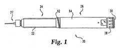
- Fig. 1generally illustrates one type of medication delivery device in which the injection clicker assembly of the present invention finds beneficial application.
- the shown delivery deviceis a reusable, medication injection pen, generally designated 20.
- injection pen 20includes a medication filled cartridge 22 as part of a cartridge assembly, generally designated 24, which is connected to a reusable pen base, generally designated 26.
- Pen base 26preferably includes dose setting and injecting mechanisms that function to allow a quantity of medicine to be selected and then expelled from cartridge assembly 24 through the injection needle assembly 27 shown attached thereto.
- an exposed knob 28 with rotatable button 30 thereon at the rearward or proximal end of pen base 26is a manually operable portion of the dose setting and injecting mechanisms otherwise housed within pen base 26.
- knob 28is designed to be rotatable to set the dose, and when knob 28 is so rotated to increase the selected dose the knob 28 and button 30 translate out of pen base 26 from the axial position shown in Fig. 1 , or to the right from the perspective of a Fig. 1 viewer.
- button 30 and knob 28are designed to be shifted to the left, and back to the axial position shown in Fig. 1 , to cause the injecting mechanism components housed within the pen base to operate to cause the medicine in the cartridge to be injected.
- the foregoingis provided as background and is intended to be illustrative and not limiting in any way, as a variety of injectors, having varied manual dose setting and injecting mechanisms, and having varied external shapes and sizes, are known in the injection pen art.
- the drive assemblymay be readily adapted for many of such mechanisms in view of the explanation herein, as the drive assembly described further below in theory may be incorporated into any type of injecting mechanism that during injection rotates a rotatable drive element that inputs a rotational force to the drive assembly. Additionally, the drive assembly is applicable to autoinjectors having rotatable drive elements, and further does not require the presence of a dose setting mechanism that allows variability in the quantity to be delivered.
- cartridge assembly 24is assembled from component parts during its production into a unit handled by a user as a single piece, and disposed of as a unit when the contained medicine is exhausted.
- Cartridge 22 of cartridge assembly 24includes an open-ended glass housing 32 that defines an internal volume filled with medicine such as human growth hormone or insulin.
- a slidable plunger 34engages inner surface 33 of the cartridge housing in a fluid-tight manner.
- a rod tip 35 used to distribute advancing forces applied to plunger 34, and which is freely movable within the cartridge internal volume located proximally of plunger 34,has a base disc 37 integrally formed with a cylindrical collar 38 in which fits the distal end 121 of drive screw 120 of the inventive drive assembly.
- distal end 121 of drive screw 120can directly, as opposed to indirectly, engage plunger 34.
- a foot which has a larger diameter than the drive screw and which is designed to rotate relative to the drive screwmay be rotatably mounted on distal end 121 to directly engage the cartridge plunger.
- Cartridge 22is further protected by an outer housing 42, which is shown as being transparent but may be otherwise constructed. At its rearward end, outer housing 42 includes an externally threaded, stepped-down neck portion 44, and a further stepped-down rear hub 46 in which extends the rearward end of rod tip 35. Threaded neck portion 44 allows for a threaded or screw attachment of cartridge assembly 24 to pen base 26.
- Cartridge assembly 24includes cap 50 that is secured during production, such as by ultrasonic welding, to outer housing 42 to capture cartridge 22 within the outer housing.
- a pierceable rubber septum 54is pressed by cap 50 against cartridge housing 32 to seal the open forward end of the housing. External threads on cap 50 allow mounting of injection needle assembly 27. When assembly 27 is so mounted, the rear end of its needle pierces septum 54, and medicine is expressed from cartridge 22 through the needle when plunger 34 is driven to the left in Fig. 1 during injecting use of pen 20.
- the cartridge assembly which is acted upon by the drive assembly of the present inventionmay be differently configured such as is known in the art.
- the cartridge assemblymay be provided as a reusable retainer which is connectable in suitable fashion, such as via threads, to a reusable pen base, and which retainer defines a chamber into which a disposable cartridge is loaded for use.
- a userdisconnects the retainer from the pen base, removes the spent cartridge from the open proximal end of the retainer and disposes of that cartridge, and then inserts a replacement disposable cartridge into the retainer which is then reconnected to the pen base for use, which cartridge replacement process can be repeated as necessary.
- cartridge assembliesmay be used, such as a cartridge assembly that includes a disposable cartridge made of plastic and without an outer protective cover, and which attaches directly to the pen base, as well as a cartridge assembly that includes a replaceable cartridge, which mounts or inserts within a chamber of the device, and a cover element for the cartridge-receiving device chamber, such as a separate cap piece or an access door that is slidably or pivotally connected to the device.
- the drive assemblyincludes a floating nut 60 located within the interior hollow of pen base 26 defined by the pen base exterior housing.
- the distal end of the pen base exterior housingincludes a cartridge interface member 62 fixedly secured, such as by gluing, plastic snap fit or ultrasonic welding, to a rearwardly extending housing body portion 64.
- Interface member 62is internally threaded at 66 for connection to the externally threaded stepped-down neck portion 44 for mounting cartridge assembly 24 to pen base 26.
- External threading 63 of interface member 62allows mounting of a not shown main cap of injection pen 20.
- the drive assemblyalso may be used with other housing configurations.
- Floating nut 60is molded in one piece from plastic and includes a generally cylindrical, tubular body section 70 which is preferably keyed to the pen base housing to allow the nut to travel in an axial direction therein while preventing rotational motion of the nut within the housing at any given axial position.
- a suitable keyingincludes radially projecting keys 74 located adjacent the rearward end of nut body section 70 which fit within axially aligned grooves or keyways 65 formed in housing body portion 64. In the shown arrangement, three equally angularly spaced keys 74 are provided, but additional keys, or fewer keys including only a single key, may be employed.
- nut 60may be keyed to the pen base housing by keys furnished on the housing that fit within keyways formed in the exterior of the nut.
- the hollow interior 71 of tubular body section 70is spanned by disk portion 80 of nut 60.
- the portion of hollow interior 71 located forward of disk portion 80is sized to freely rotatably receive hub 46.
- a central opening 81 defined by disk portion 80is formed with internal threads 82 designed to mate with external threading 124 of the drive assembly screw 120.
- a pair of drive clutch retainers 85are provided on opposite sides of central opening 81.
- Each drive clutch retainer 85is a rim or latch portion 87 integrally formed with and projecting radially inwardly from body section 70.
- Floating nut 60is forced toward the forward end of pen base 26 by a biasing element acting between nut 60 and, for example, the pen base housing.
- a biasing elementis a metal, helical compression spring 90 having a forward end 91 that directly abuts the annular end face 72 of body section 70, and a rearward end 92 that directly abuts a protruding bulkhead 93 of housing body portion 64.
- the rear end surface 67 of interface member 62provides an axial stop against which the forward face 75 of each nut key 74 abuts to limit forward axial movement of nut 60 by spring 90.
- Alternate biasing elementssuch as different types of springs and different materials of construction, may be substituted in other arrangements.
- the rearward end of the biasing elementalternatively may abut a pen component that is connected to, rather than integrally formed with, the housing.
- drive clutch 100 of the drive assemblyis connected to floating nut 60 to be rotatably free and axially fixed.
- Drive clutch 100has a disk shaped body 102 ringed completely by a radially outwardly projecting snap ring 104.
- latching mechanismsto axially retain the drive clutch within the floating nut while permitting relative rotation therebetween, including different numbers of rim portions or rearwardly extending, axially aligned prong portions from which a latch portion projects radially inward, also may be substituted in alternate arrangements.
- Body 102 of drive clutch 100defines a central opening 110 and has at least one inwardly extending V-shaped portion or key 112 projecting within the opening.
- Key 112fits within a corresponding keyway channel 122 longitudinally extending along the length of drive or lead screw 120, which includes external threading 124 that engages threading 82 of floating nut 60.
- two diametrically arranged keys 112fit within longitudinal keyways 122 located on opposite sides of the drive screw. The interfitting of keys 112 with keyways 122 causes forced rotation of drive clutch 100 during injection to rotate drive screw 120, and similarly causes forced rotation of drive screw 120 during reset to rotate drive clutch 100.
- Drive clutch 100is adapted to engage a rotatable drive member of the injecting mechanism for torque transmission.
- the outer radial region of proximal surface 113includes a series of axially projecting, generally triangular shaped teeth 114 arranged in an annulus, which teeth are structured and arranged to mate with similarly configured teeth 130 provided on drive member 135.
- Each tooth 114includes a ramped side 116, and an axially aligned side 118 to which force is directly applied by a tooth 130 during driving rotation of drive clutch 100 by drive member 135.
- different torque transmitting configurationsincluding flat plates relying exclusively on friction for non-slipping torque transmission, may be substituted for the particular toothed configuration shown.
- the rotatable drive member 135rotates when injection pen 20 is operated to cause fluid to be ejected through needle assembly 27.
- Drive member 135is diagrammatically shown as an annular disc 140 rotatably fixed to a sleeve 142 journaled within the injection pen and through which extends drive screw 120.
- Annulus 140includes the forwardly extending teeth 130.
- the drive assemblymay be driven by differently designed rotatable drive members.
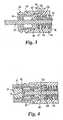
- the drive assemblywill be further understood in view of the following explanation of aspects of the operation of injection pen 20, starting with the injection pen configured as shown in Fig. 2 which occurs when a new cartridge assembly 24 is replacing an exhausted cartridge assembly that is not shown.
- the userwill first assemble cartridge assembly 24 to pen base 26.
- a userwill hold reusable pen base 26 in one hand, and cartridge assembly 24 in the other hand, and first maneuver the components such that distal end 121 of drive screw 120 is inserted within hub 46 and rod tip collar 38, and into contact with rod tip base disc 37.
- Pen base 26 and cartridge assembly 24are then manually moved together in an axial direction until hub 46 is axially introduced into the pen base hollow interior and the external threads of stepped-down neck portion 44 initially abut internal threads 66 of cartridge interface portion 62.
- rod tip 35is first moved farther into cartridge 22 to close up any spacing that may have existed between it and plunger 34, and then drive screw 120 is forced axially and screws through floating nut 60 while drive clutch 100 freely spins with drive screw 120 and within floating nut 60.
- the drive screw 120is so pushed back or reset, rather than plunger 34 being forced to slide within cartridge 22, due to the relatively low frictional resistance to reset of the drive assembly.
- cartridge assembly 24is then rotated relative to pen base 26 to screw the components together.
- annular shoulder 45contacts end surface 76 of floating nut 60 that is in a forward axial position due to biasing by spring 90.
- other portions of the cartridge assemblysuch as the rearward end of hub 46, may be the point of contact with nut 60.
- the cartridge assemblymay indirectly engage the nut, such as via an interposed member made of a low friction material.
- shoulder 45slides along floating nut end surface 76 as the cartridge assembly rotates and move axially, while nut 60 moves axially without simultaneously rotating.
- the resisting force generated by spring 90which increases as the insertion progresses, reduces play between cartridge assembly 24 and pen base 26 to provide injection pen 20 with a more solid or well-constructed feel to a user, and to limit pen drooling that can occur during relative movement of the cartridge and the drive screw.
- Cartridge assembly 24is fully mounted after it has been screwed in until end face 43 of barrel 42 abuts the distal face of cartridge interface member 62, which arrangement is shown in Fig. 4 .
- nut 60 and the retained clutch 100are in a rearward axial position at which teeth 114 of drive clutch 100 are positively engaged with teeth 130 of drive member 135 in a non-slip fashion so clutch 100 can be rotated by rotation of drive member 135.
- buttons 28 and 130which is mechanically interconnected with sleeve 142 of drive member 135, rotates drive member 135 to rotate the drive clutch 100 and thereby drive screw 120, which screws out through nut 60 to advance plunger 34 to force medicine from the needle equipped cartridge assembly 24.
- FIG. 7there are diagrammatically shown portions of another injection pen equipped with a drive assembly similar to that of figs. 2-6 .
- the reusable pen base 226is similarly constructed to that shown in Fig. 3 , and further the drive assembly is the same as that shown in Fig. 3 other than end 121 of drive screw 120 being configured to rotatably support an added foot 123.
- Foot 123is attached so as to be freely rotatable about the axis of screw 120 during use and serves to distribute pressure on plunger 34.
- the cartridge assembly in Fig. 7is in the form of a reusable retainer 230 with a disposable cartridge loaded therein, which cartridge is similar to cartridge 22 but lacks a rod tip 35.
- Retainer 230is connectable to the pen base housing such as via threads shown at 232.
- Cartridge 22is insertable into, and removable for replacement from, the retainer through the open rearward end of the retainer when the retainer is not connected to pen base 226.
- floating nut 60directly contacts the cartridge housing 32, and the spring biasing of the nut forces cartridge 22 forward within the retainer against the interior surface of a not shown forward end of the retainer.
- Cartridge 22is thereby prevented from moving relative to nut 60.
- the drive clutchneed not be held by the floating nut, but instead is simply shifted into engagement with the drive member by, for example, abutting contact with the floating nut.
- the springoperably engages the drive clutch to bias it out of engagement with the rotatable drive member when no cartridge assembly is properly mounted to the pen base.
- the forward end of a springmay abut a washer member which holds forward the drive clutch, such as in contact with the floating nut.
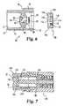
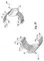
- Figs. 8-11show injection clicker assemblies of the present invention, which assemblies are for a medication injector apparatus, such as injection pen 20 of Fig. 1 .
- inventive injection clicker assemblymay be readily adapted for many alternately configured injectors in view of the explanation herein, as the inventive injection clicker assembly described further below in theory may be mounted on rotatable drive sleeves of injecting mechanisms which are turned by operation of differently configured components of those injecting mechanisms. Additionally, the injection clicker assembly does not require the presence of a dose setting mechanism that allows variability in the quantity to be delivered.
- one form of the injection clicker assembly of the present inventionincludes a ring-shaped collar or clicker element, generally designated 240.
- a ring-shaped collar or clicker elementgenerally designated 240.
- the pen shown in Fig. 8includes, for example, a drive assembly which is slightly different than that which is described above with respect to pen 20, as well as a cartridge assembly that comprises a reusable retainer 238, which is threadably connected to the pen base housing, and a disposable cartridge 22 loaded therein.
- Annular collar 240defines a central bore through which drive sleeve 242 extends such that collar 240 is coaxially mounted on drive sleeve 242. At least one rib or key, such as a pair of diametrically opposed keys 244, inwardly project within the central bore of collar 240 and slidably fit within longitudinally extending slots or keyways 246 on opposite sides of drive sleeve 242. The keying of collar 240 with drive sleeve 242 results in collar 240 being rotatably fixed but axially movable relative to drive sleeve 242. In an alternate embodiment, collar 240 can be keyed to drive sleeve 242 with mating keys and keyways that are on the drive sleeve and collar respectively.
- the proximal face of collar 240is formed with a ring of axially extending teeth 248. Teeth 248 mesh with complementary teeth 250 that are molded into bulkhead 252. The number of collar teeth 248 and teeth 250 to which it engages need not be in a 1 to 1 ratio, as the clicker may have, for example, every other tooth removed.
- Bulkhead 252is an additional component splined to the pen outer housing portion 254, which outer housing is shown as an assembly of multiple component parts, such that bulkhead 252 is rotatably fixed relative to the pen housing during injecting use of the pen. Bulkhead 252 is axially fixed in the embodiment of Fig. 8 by being pressed by a spring 256 against a lip portion of the pen outer housing. In alternate embodiments, mating teeth 250 may be part of a bulkhead integrally formed with the pen outer housing.
- Teeth 248 and 250are configured such that when in meshed engagement, only unidirectional rotation of collar 240 relative to bulkhead 252, and thereby to the pen housing, is permitted. During such relative rotation, the collar teeth 248, when traveling across teeth 250, generate audible clicking noises.
- the unidirectional rotatability of collar 240allows it to function as an anti-backup mechanism for the drive sleeve and injection screw as described further below.
- teeth 248 and 250may be differently configured so as to not prevent reverse rotation and to thereby allow bi-directional collar rotation.
- Injection clicker 240is biased in the proximal axial direction along drive sleeve 242 by a biasing element, generally designated 258.
- the biasing elementis a coiled compression spring made of metal which is coaxially mounted on drive sleeve 242, but other types of springs or materials of construction alternatively may be employed.
- spring 258backs up collar 240 to provide injection clicks and rotational positioning.
- springs of various strengthcan be tested in order to select a spring that provides a suitable clicking noise without modifying either the bulkhead or the collar design.
- the distal end of spring 258abuts a proximal facing surface of a radially protruding disk portion 260 of drive sleeve 242.
- the distal facing surface of disk portion 260includes a ring of axially extending teeth 262 that are used to transmit rotational motion of the drive sleeve to a drive assembly that advances the injection screw.
- the drive assemblyincludes a clutch 266 with proximal teeth 264 that mate with disk portion teeth 262 when the pen is fully assembled as shown in Fig. 8 .
- Clutch 266is keyed to threaded injection screw 270 via keys 268 that fit within diametrically disposed keyways 272 longitudinally aligned along the screw that extends through drive sleeve 242. Clutch 266 is axially retained within, but rotatable relative to, a floating nut, generally designated 275, by way of tangs 277 that snap fit over the clutch during assembly. Floating nut 275 is keyed to the pen housing to be axially movable but rotatably fixed.
- Floating nut 275is biased distally by spring 256 when cartridge retainer 238 and cartridge 22 is disassembled from the pen base so as to disengage the drive sleeve teeth 262 from clutch teeth 264 to allow injection screw reset.
- drive sleeve 242is moved distally by the action of spring 258 against disk portion 260, but is prevented from engaging clutch 266 by the abutment of disk portion 260 against the not shown keys of pen housing portion 255 to which floating nut 275 is keyed.
- Fig. 8The injection clicker assembly of Fig. 8 will be further understood in view of the following explanation of its operation within a pen such as pen 20.
- pen 20When pen 20 is in the configuration shown in Fig. 1 , which is a ready state prior to dose dialing for injection, the teeth of drive sleeve disk portion 260 and clutch 266 are engaged, and the teeth of collar 240 and bulkhead 252 are engaged as shown in Fig. 8 .
- spring 258maintains collar teeth 248 in meshing engagement with bulkhead teeth 252. Due to the unidirectional rotatability of collar 240 and its keying to drive sleeve 242, this teeth meshing rotationally locks drive sleeve 242.
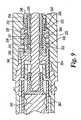
- FIG. 9-11another form of an injection clicker assembly of the present invention is shown in a different partially shown injection pen.
- This injection clicker assemblyis particularly adapted for an injecting mechanism having a drive sleeve part that shifts axially during injecting operation.
- the injection clicker assemblyincludes a ring-shaped collar or clicker element, generally designated 290.
- Annular collar 290defines a central bore 292 through which tubular base 335 of the drive sleeve extends.
- At least one rib or keysuch as a pair of diametrically opposed keys 294, inwardly project within bore 292.
- Keys 294fit within longitudinally extending keyways 340 on opposite sides of drive sleeve base 335 such that collar 290 is rotatably fixed but axially movable relative to the drive sleeve.
- the proximal face of collar 290is formed with a ring of axially extending teeth 296. Teeth 296 mesh with complementary teeth 347 molded into a bulkhead 348 integrally formed with the diagrammatically shown pen outer housing.
- Each tooth of teeth 296includes an axially aligned surface 297 and a ramped surface 298 extending to the axially aligned surface of the successive tooth, which teeth configuration permits unidirectional rotation of collar 290 relative to the pen housing that allows the collar to function as an anti-backup mechanism. During such relative rotation, the collar teeth 296, when traveling across the pen housing teeth 347, generate audible clicking noises.
- Injection clicker 290includes a distal surface 300 which at times during pen operation is abutted by a radially aligned, outer region 307 of a retainer ring, generally designated 305.
- Ring 305includes a forwardly angled, central portion 309 which interference fits during pen assembly into a circumferential groove 343 formed in drive sleeve base 335. This connection causes retainer ring 305 to follow the axial movement of drive sleeve base 335 during operation, which axial movement is a function of the particular injecting mechanism of the pen.
- Retainer ring 305serves to restrict axial motion of collar 290 when the drive sleeve is axially positioned as shown in Fig. 9 , such as during dose dialing, by its outer region 307 engaging surface 300, thereby preventing the disengagement of collar teeth 296 from housing teeth 347.
- Collar 290is biased in the proximal axial direction by a coiled metal compression spring 320 coaxially oriented around drive sleeve body 335.
- the proximal end 321 of spring 320fits around a stepped-down diameter neck portion 302 of collar 290.
- Spring end 321is pressed over and retained by six ribs 303 spaced at even intervals around the neck portion circumference.
- the distal end 322 of spring 320fits around a stepped-down diameter neck portion 332 of a radially protruding, torque-transmitting member 330 of the drive sleeve, generally designated 325.
- Drive member 330is the portion of the drive sleeve which transmits rotational drive sleeve motion to a clutch 350 keyed to drive screw 354.
- Six ribs 331 evenly spaced around neck portion 332are pressed into the distal end 322 of spring 320 during pen assembly to retain spring 320 to drive member 330.
- the distal facing surface of drive member 330includes distally, axially extending teeth 333 that mate with teeth on clutch 350 when the pen is assembled for use.
- the drive sleeveis a two part assembly, as radially protruding drive member 330 is configured to allow limited axial movement relative to tubular base 335 of the drive sleeve, which base is caused to rotate when the injecting mechanism of the pen is operated.
- This ability of relative motionaids in preventing clutch binding when a cartridge assembly is mounted to the pen base.
- drive member 330can back up allowing the cartridge assembly to be fully installed without locking up or damaging the clutch teeth, and any tooth to tooth condition that remains after installation is automatically addressed upon pen priming.
- This ability of relative motionalso allows for the axial movement of the drive sleeve tubular base during injecting operation, which movement is a function of the overall injecting mechanism of the pen.
- a pair of diametrically opposed keys 337project radially inwardly. Keys 337 fit within longitudinally extending keyways 340 such that member 330 is rotatably fixed but axially movable relative to drive sleeve base 335.
- a pair of diametrically opposed snaps or ribs 338also project within bore 334 at locations offset ninety degrees from keys 337.
- ribs 338snap-fit into recesses 341 formed on the periphery of drive sleeve base 335 and in spaced apart relationship from distal end 342.
- Recesses 341extend in the axial direction greater than the thickness of ribs 338 so as to permit the limited axial movement of drive member 330 relative to base 335.
- the snap-fit connectionprevents the drive sleeve assembly from coming apart axially when a medication cartridge is disassembled from the pen base, and further insures that the forward travel of drive member 330 is limited by drive sleeve base 335 to aid in disengagement of drive member 330 from clutch 350 when a cartridge assembly is removed.
- the teeth 333 of drive member 330mate with a clutch of a drive assembly utilized to shift the injection screw distally.
- the drive assembly shown in Fig. 9has a clutch 350 internally keyed to a threaded drive screw 354 that extends through drive sleeve base 335.
- Clutch 350is connected to a rotatably fixed floating nut 360 which threadedly engages drive screw 354. Rotation of clutch 350 via the drive sleeve 325 rotates drive screw 354, which screws through nut 360 to advance in the distal direction beyond the end of the reusable pen base to shift movable plunger 365 of cartridge 367 so as to force medication from an outlet of the cartridge.
- Floating nut 360is biased distally by spring 369 when the cartridge assembly is removed so as to disengage the drive assembly from drive sleeve teeth 333 to allow injection screw reset.
- This drive assemblyis more fully described above.
- Other drive assemblies with a clutch that operably engages drive sleeve member 330 when the pen is assembled for usemay be used in devices with the inventive injection clicker assembly.
- drive sleeve base 335When the injecting mechanism is manually operated during an injecting use of the dialed up pen, drive sleeve base 335 first moves distally to shift retainer ring 305 distally such that collar 290, subject to overcoming the biasing force of spring 320, is movable distally. The drive sleeve body 335 then begins to rotate, and teeth 296 of collar 290 shift in and out of engagement with the housing teeth producing injection clicks. The drive sleeve rotation also causes the drive clutch 350 to rotate which screws the injection screw 354 through floating nut 360. During this injecting process, if the floating nut floats proximally slightly, the compressed spring 369 forces it back toward the pen distal end to finish the injection.
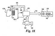
- a therapeutic dose indicating apparatusis housed in a delivery device 420 and utilizes an automatic container recognizer 422, a doseable quantity identifier 424, a controller 426, and a display 428.
- a delivery devicefor which the system is particularly well suited is an injection pen, but other types of portable devices, such as a pulmonary device or inhaler, may be similarly equipped.
- Automatic container recognizer 422functions first to recognize a characteristic of a container insert into delivery device 420, which characteristic relates to a concentration of the medicine within the container, and then to input that information to controller 426 as shown at 430.
- Doseable quantity identifier 424functions first to sense the arrangement to which the dose setting mechanism of delivery device 420 has been manipulated by a user to prepare the device to deliver a finite volume of medicine, and then to input that information to controller 426 as shown at 432. In response to the input information, controller 426 calculates the therapeutic dose to be delivered and instructs display 428 via line 434 to visibly display that dosage to a user of delivery device 420.
- injection pen 440includes a cartridge assembly, generally designated 442, which is connected to a pen base, generally designated 444, which houses dose setting and injecting mechanisms that when operated cause a quantity of medicine to be selected and then expelled from cartridge assembly 442 through injection needle assembly 467.
- cartridge assembly 442is further shown in cross-sectional view in Fig. 14 and is, but for the identifier described below, the same as the cartridge assembly 24 of Fig. 2 .
- cartridge assembly 442includes a cartridge 446 with a glass housing 448 that defines a medication-filled internal volume.
- the cartridgeincludes slidable plunger 449, rod tip 452, cap 464 and septum 466.
- Cartridge 446is further protected by an outer housing or barrel 458 that includes an externally threaded, stepped-down neck portion 460, and a further stepped-down rear hub 462. External threads 468 on cap 464 allow mounting of injection needle assembly 467 that pierces septum 466.
- the automatic container or cartridge recognizer 422 of injection pen 440includes an identifier associated with cartridge assembly 442 which is designed to work with a sensor that signals controller 426 within pen base 444 based on the identifier sensed.
- the identifiercan take many forms and be used to indicate a variety of facts to the user.
- the identifieris used to represent the concentration of the therapeutic contents of the cartridge assembly, and which concentration identifier is disposed on the outer housing hub 462 of cartridge assembly 442.
- the concentration identifierpossesses specific characteristics, such as dimensional and spatial characteristics, recognizable by the sensor of automatic cartridge recognizer 422.
- the identifiermay be placed on other portions of the cartridge assembly, including but not limited to cartridge housing 448, and rod tip 452, and further may be used to represent, for example, which one of different possible insulin types is contained in the cartridge assembly.
- the concentration identifieris permanently affixed to the cylindrical exterior surface of hub 462.
- the identifierneed not be exposed on the periphery of hub 462, and may be differently positioned such as affixed to the interior surface of hub 462.
- the cartridge concentration identifieris shown formed by a single strip of electrically conductive material fixedly associated with hub 462.
- the shown stripextends the entire hub circumference, but may span only a part of the circumference if the associated sensor contacts of container recognizer 422 described below are configured to achieve a satisfactory connection despite one or more circumferential gaps in the strip.
- the conductive stripmay be in the form of a pad printed conductive ink applied to the hub, however, other means of accomplishing the identifier strip may be employed.
- the stripmay be a crimped metal band, or a conductive electroplating of a material insert molded into the hub, or a conductive paint, or a pad printed ink, or a metallic self-adhesive label, or a non-conductive adhesive label onto which an appropriate electrically-conductive pattern has been applied.
- hubs 462a, 462b and 462c of three different cartridge assemblies 442a, 442b and 442c each compatible with pen base 444are shown.
- the type of content identifier shown being used on hubs 462a, 462b and 462cuses the dimensional aspect of the width of the conductive strip, along with the spatial aspect of the placement of that strip on a hub, to represent the cartridge contents.
- This type of content identifierhas particular applicability to identifying the concentration of hGH, which has a limited number of common concentrations, and therefore the three cartridge assemblies shown in Figs. 15-17 each contain hGH in a different concentration.
- the dimensional aspect of the identifier stripmay be different than the width, such as the thickness or texture of the strip.
- a conductive strip 472 having a relatively small widthsuch as about 4.8 mm, encircles hub 462a of cartridge assembly 442a near the distal end of the hub which is adjacent the threaded neck 460a of the barrel.
- a conductive strip 474 having a relatively small widthsuch as about 4.8 mm, encircles hub 462b of a second cartridge assembly 442b near the proximal end of the hub.
- the axial region of hub 462c covered by strip 476is the same as would be covered by strips 472 and 474 if positioned on hub 462c at the same locations as such strips are positioned on hubs 462a and 462b, respectively.
- the content identifier of that mounted cartridge assemblyprovides a conductive path between a series of sensor contacts within the device which are spaced along the axial length of the inserted hub.
- the varying widths and locations of the content identifiers of the various cartridge assembliesprovide different conductive paths between the sensor contacts.
- the senorincludes electrical contacts 480, 481 and 482. Although these sensor contacts are shown in Fig. 18 as being in exact axial alignment, each of sensor contacts 480-482 may be angularly spaced from the other sensor contacts, such as within a 60° circumferential span or 120° apart, or such other angular spacing as may be possible within the pen base interior hollow. Furthermore, each sensor contact naturally could comprise a plurality of contacts circuited in parallel and positioned at the same axial hub location.
- the sensor contactsmay be resilient metal fingers extending from a subassembly base pivotally mounted to, for example, the housing, and circuitry on the base is electrically connected to a circuit board of controller 426.
- the subassembly baseis rotationally biased such that hub contact portions of the metal fingers are in a radially retracted position when no cartridge assembly is mounted to pen base 444.
- a pivot arm of the subassembly baseis contacted, causing the subassembly base to rotate such that the contact portions of the fingers are moved into communication with the content identifier.
- the fingersmay be resilient or leaf spring type metal fingers which are biased radially inward into contact with the hub and which are mounted, for example, to the pen base housing or to a part movable within the housing of pen base 444 itself, which fingers slide along the hub as the hub inserts during connection of cartridge assembly 442 to pen base 444.
- Controller 426processes the data related to which of the sensor contacts within injection pen 440 are in communication with the conductive strip of the content identifier and derives information from a look-up table to essentially read what is represented as being within the cartridge assembly.
- sensor contacts 480 and 482are directly circuited with controller 426 by lines 484 and 486, which lines may be patterns imprinted on a circuit board of controller 426.
- Sensor contact 481is similarly circuited to controller 426 by line 488 which is grounded at 490.
- grounded sensor contact 481is in communication with identifier 474, and the conductivity of identifier 474 is used to ground sensor contact 482 and thereby line 486 to controller 426.
- the concentration in mg/mlcan be readily obtained by dividing the referenced milligram mass by the 2.88 milliliter volume of the cartridge contents when reconstituted.)
- identifier 472is used to ground sensor contact 480 and line 484 to controller 426, but sensor contact 482 and line 486 is not grounded, thereby resulting in controller 426 being signaled that line 486 remains open while line 484 has been closed such that controller 426 equates this input to a different hGH concentration, such as 6 mg, being present within the loaded cartridge assembly 442a.
- the cartridge recognition systemcould have more or less than the three contact points shown in Fig. 18 , and could use recognizable electrical signals other than ground, such as a small voltage, to activate the content identifiers.
- the cartridge assemblymay be differently configured such as is known in the art, and such as described above.
- the content identifierwill be provided on the disposable cartridge, and pen base 444 will be correspondingly modified to permit recognition of that cartridge, such as by incorporating part of the recognition system, for example electrical contacts and wiring, into the retainer, or by configuring the pen base components, such as the contacts, to extend within the chamber of the retainer.
- Doseable quantity identifier 424includes a rotational matrix, generally designated 500, and a sensor array, generally designated 502, which together are arranged to identify adjustments of the pen mechanism used at least in dose setting, as well as preferably in dose injecting after its dose setting.
- a variety of mechanisms for setting and injecting a doseare known in the injection pen art and are therefore not explained in exhaustive detail herein.
- the doseable quantity identifiermay be readily adapted for such and newly developed mechanisms in view of the explanation herein, the particulars of such mechanisms explained further herein are intended to be illustrative and not limiting.
- doseable quantity identifiers of known designwhich communicate with a controller may be substituted for the rotational matrix/sensor array within the therapeutic dose indicating apparatus.
- Rotational matrix 500 and sensor array 502are operably connected to first and second components of injection pen 440 which experience relative rotational motion during operation of the dose setting mechanism by a user to select a volume desired to be injected.
- the dose setting mechanismincludes a rotatable dial 506 into which is incorporated rotational matrix 500.
- Dial 506is rotationally fixed to an exposed knob 508 that is rotatable by the user to select the dose to be delivered by use of the injection pen.
- dial 506when rotated via knob 508 translates out of pen base 444, or to the right from the perspective of a Fig. 13 viewer, during the dialing up of a dose in preparation for dose injecting.
- the matrixneed not be on a dial that so translates, but may be on another rotatable component such as a drive sleeve.
- first and second relatively rotatable pen componentsare part of the dose setting mechanism in the arrangement of Fig. 19
- the other of these components to which sensor array 502 is connectedmay be the outer housing of pen base 444
- the first and second componentseach may be parts of the dose setting mechanism in other arrangements.
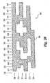
- matrix 500is data arranged in a rectangular array formed of multiple orthogonally intersecting rows and columns.
- the number of columnsis a function of the internal workings of the injection pen, and corresponds to the number of rotational positions within one of its revolutions at which dial 506 can be set to have the injection pen deliver different volumes of medicine.
- the movement of dial 506 between adjacent rotational positionscorresponds to a change by one dose volume unit of the quantity to be injected by pen operation, and such change is known as a "click" due to the setting mechanism, as a result of its configuration, producing an audible click-like noise during such movement.
- the actual quantity of such dose volume unitfor example .024 ml, is a function of the design of the dose setting mechanism as is known in the art.
- the data populating matrix 500is in the form of the presence or absence of an electrically conductive material at the intersections of the rows and columns, which electrically conductive data points are shown contiguous or all linked to form a pattern 501 structured and arranged in conjunction with the sensor contacts of array 502 to convey information to controller 426 of pen 440.
- the linkingallows an electrical signal delivered to a single data point on pattern 501, such as a grounding of that point, to travel along the entire pattern as described further below.
- Each of the six rows 509, 510, 511, 512, 513 and 514 of matrix 500extends around the entire circumference of dial 506.
- the twenty-four matrix columns 516, 517, 518,519,520,521,522,523,524,525,526,527,528,529,530,531,532,533,534,535, 536, 537, 538 and 539are equal width, so as each to span 15° of the dial circumference, and are aligned in parallel with the axial length of dial 506.
- column 516is unpopulated by any electrically conductive data points and is formed by a circumferential gap between the ends of the conductive pattern portion that otherwise fills row 509 (i.e.
- the electrically conductive pattern 501 of matrix 500may be fabricated by two-shot molding a platable material, such as filled styrene plastic, into an electrically non conductive or insulating sleeve, which molded material is then plated with a conductive material, such as successive layers of copper, nickel and then gold, so as to be electrically conductive. After plating, the sleeve is fixedly attached to dial 506. To facilitate manufacture, such as to provide a fixturing point needed to position the required pattern, the conductive pattern 501 of matrix 500 may include a not shown extension beyond the matrix rows or columns, but which extension is not used by sensor array 502.
- the matrix patternmay be otherwise manufactured, such as a sheet metal matrix insert molded onto a sleeve, or such as in ways similar to those described above with reference to the cartridge content identifiers, for example via a metallic pattern on a non-conductive self-adhesive label or flexible circuit board attached to the dial, or by conductive paint or pad printed conductive ink applied directly to the dial.
- Sensor array 502operationally engages matrix 500 to sense the matrix data.
- sensor array 502includes resilient or leaf-spring type metal contacts 546, 547, 548, 549, 550 and 551 which extend radially inward from a cylindrical base sleeve 544 coaxially arranged on dial 506.
- Each of sensor contacts 546-551abuts matrix 500 within a different row, and in the shown arrangement sensor contacts 546, 547, 548, 549, 550 and 551 are respectively aligned with matrix rows 509, 510, 511, 512, 513 and 514.
- Sensor contacts 546 and 549are installed at a first circumferential position of base sleeve 544
- sensor contacts 547 and 550are installed at a second circumferential position of base sleeve 544 which is spaced 120° from the position of contacts 546 and 549
- sensor contacts 548 and 551are installed at a third circumferential position of base sleeve 544 which is spaced 120° from the positions of both contacts 546 and 549, and contacts 547 and 550. This even angular spacing of the sensor contacts around the matrix serves to center the matrix and limit frictional resistance.
- dial 506when dial 506 is rotationally oriented relative to sensor array 502 such that contacts 546 and 549 each abut matrix 500 within, for example, column 516, contacts 547 and 550 each abut matrix 500 within column 524, and contacts 548 and 551 each abut matrix 500 within column 532.
- sensor contact 546which serves as the grounding contact as described below
- thisis the "home" or “zero” position of the dial.
- the dialWhen the pen is manipulated such that no volume of medicine will be delivered if the injecting mechanism of the pen is operated, the dial will be in this home position. At the home position, the ground is not electrically connected with any of the other contacts 547-551.
- the matrix patterncan be adapted to indicate this home position even if, for example, the conductive pattern filled all of row 519 including column 516. For such a matrix pattern, the pattern would also be configured to not be in contact with any of the other sensor contacts 547-551 when sensor contact 546 was aligned with column 516.
- Matrix pattern 501 shown in Fig. 20is designed complementary to this contact arrangement.
- Matrix pattern 501uses a gray code coding scheme to reduce the risk of an error in dial position sensing going undetected.
- the patternis configured in view of the sensor positioning such that rotational dial movement, in either direction and in an amount equal to one column, causes only a single one of sensor contacts 547-551 to switch its electrical circuiting relationship with the pattern, which single switching can be monitored by the controller (i.e. only one sensor contact changes from being out of contact with the pattern to being in contact with the pattern, or vice versa, when dial rotation causes each sensor contact in its respective given column to be moved to a column on either side of that given column).
- each of the twenty-four rotational set positions of dial 506 relative to sensor sleeve 544results in a unique set of information being recognized by operation of sensor contacts 546-551.
- sensor array 502 and rotational matrix 500are rotatably free and axially fixed relative to one another.
- sensor array 502may be keyed to, for example, the housing of pen base 444 so as to be free to translate with, but not rotate with, dial 506 when the dial is rotated and thereby caused to translate during dose setting. Not shown connections between dial 506 and sensor array 502 may be used to cause sensor array to translate with the dial.
- Sensor contacts 546-551 of array 502are each circuited to controller 426 as abstractly represented at line 432 such that sensor input can be used by controller 426 to derive the matrix positioning using a look-up table in a similar manner as described above with respect to the automatic container recognizer. For example, during use a ground signal is sent to sensor contact 546, which is in contact with and grounds matrix pattern 501 at all rotational dial positions except when sensor contact 546 is aligned in matrix column 516. When electrically conductive matrix pattern 501 is so grounded, each of sensor contacts 547-551 that is in contact with conductive matrix pattern 501 is also grounded.
- the set of grounded/ungrounded signals received by controller 426 via line 432 for all of the sensor contactsis used to derive the rotational position of the matrix 500, and thereby dial 506, relative to sensor array 502.
- sensor contact 546is aligned with matrix column 516, none of the contacts are grounded, which information also is recognized by controller 426 as indicative of a particular one of the twenty-four rotational positions of dial 506.
- the data of matrix 500 including areas of electrically conductive materialis due to such data serving to complete electrical circuits with electrical contacts of the sensor.
- different matrix data formsmay be used with corresponding modifications to the sensor array.
- the matrix datamay be markings or magnets, as appropriate.
- the matrix/sensor array shown in Fig. 19is merely one suitable form and may be differently arranged.
- the locations of the sensor array and matrixmay be reversed, such that a sensor array 502 circuited to controller 426 is mounted on dial 506 and arranged to engage a rotational matrix disposed on the inner circumference of coaxial sleeve 544.
- both the matrix and sensor arraymay be disposed on components of the reusable pen base which rotate at different times during dose setting and injecting use of injection pen 440.
- a slider assemblyis disposed therebetween.
- an array of sensor contacts 546'-551'are installed on a partially shown first pen component 558 coaxially mounted on a partially shown second pen component 559.
- Pen component 558is completely ringed by six electrically conductive, metal bands 560-565 that fit within channels in its outer radial periphery.
- Bands 560-565are in contact with the outward ends of sensor contacts 546'-551', respectively, that extend through the radial thickness of component 558.
- Sensor contacts 546'-551'are similarly structured and arranged to the sensor contacts of the arrangement of Figs. 19-21 , and contact a not shown rotational matrix, similar to matrix 500, that encircles pen component 559.
- Slider assembly 570includes six resilient electrical contacts 571-576 having free ends which slide along bands 560-565 as pen component 558 rotates, and such sliding contact results in an electrical connection between sensors 546'-551' and slider contacts 571-576 at any rotational position of pen component 558 relative to slider assembly 570.
- slider assembly 570may be mounted to a stationary pen base component, such as a microprocessor containing flexible circuit board fixed to the injection pen housing and which serves as controller 426. Slider contacts 571-576 are connected to circuits on this circuit board routed to the controller microprocessor. For this type of slider assembly mounting, other than limited axial play as may be required for the working parts of the injection pen, slider assembly 570 is axially and rotationally fixed within pen base 444.
- slider contacts 571-576are wired to controller 426 and slider assembly 570 is keyed to, for example, the pen outer housing and connected to pen component 558 so as to translate with but not rotate with the array of sensor contacts 546'-551'.
- the injection pen controller 426that processes signals from the sensor contacts of the automatic container recognizer 422 and doseable quantity identifier 424 to determine display information may be constructed and installed within pen base 444 in any suitable fashion known in the art.
- controller 426includes a battery-powered, programmable microcontroller mounted on a main printed flexible circuit board that is generally U-shape and flexible so as to conform to the interior of the pen base housing and to provide a hollow in which extend the internal working parts of pen base 444.
- the flexible circuit boardis connected to the housing with locating pins and adhesive.
- an application specific integrated circuit or ASICmay be substituted for the microprocessor.
- Injection pen display 428is operatively coupled to the microcontroller 426 and is visible through a transparent housing window of pen base 444.
- Display 428such as a liquid crystal display, visibly displays to a user information useful to the operation of the injection pen.
- display 428is caused by microcontroller 426 to display at 580 information about the medicine within the held cartridge as recognized by automatic cartridge recognizer 422, at 582 the amount of therapeutic the injection pen stands ready to administer upon the operation of the injecting mechanism of pen 440 as described further below, and at 584 the remaining strength of the battery that powers the electronic components of injection pen 440.
- the information shown at 580relates to the concentration of the medicine, as explained further above, but other types of information may be provided.
- the units of the dose to be administeredis shown in Fig. 13 as being imprinted on the underside of the housing window at 586, but may be part of the display controlled by microcontroller 426.
- controller 426While cartridge assembly 442 is mounted to pen base 444, controller 426 remains in a ready state with all of the display elements turned off so as to not display any information to a user. In this ready state, controller 426 processes signals received from the sensor contacts of automatic cartridge recognizer 422 to identify, for example, the concentration of the medicine contained within the cartridge assembly as represented by the identifier band. In this ready state, controller 426 also processes signals received from the sensor contacts of doseable quantity identifier 424 to identify the position of matrix 500 relative to sensor array 502.
- Controller 426advances from the ready state into the operational state, and display 428 is thereby activated, when controller 426 senses further user action on pen 440.
- action sensingwill typically be a recognition that matrix 500 is being moved relative to sensor array 502 during manipulation by the user of the dose setting mechanism.
- Other action which may be sensedis operation of a not shown on/off button which may be located on pen base 444, or as part of knob 508 of the injecting mechanism.
- controller 426When advanced to the operational state, controller 426 causes the concentration identified with automatic cartridge recognizer 422 to be displayed at 580. If controller 426 fails to recognize any concentration information, an error message such as "--,” or no message at all, is displayed at 580 instead of any numerical concentration value. Recognition failure may result from a cartridge assembly being entirely absent from, or not properly mounted to, pen base 444, or from a cartridge identifier being damaged or absent from the assembly, or from an internal failure in the automatic cartridge recognizer circuit. When concentration information is not automatically recognized, the concentration used by controller 426 may be user configurable. For example, set button 588 shown in Fig. 13 is circuited with controller 426 and is depressable to select, and have displayed at 580, any of the standard concentration values, such as 6, 12 and 24 mgs in the case of hGH, preprogrammed into controller 426.
- controller 426While controller 426 is in the operational state, as knob 508 is rotated by a user to set the dose to be delivered, controller 426 continually receives input in real time from the sensor contacts of doseable quantity identifier 424 to identify the position of matrix 500 relative to sensor array 502. Controller 426 processes the input to determine to which position the dial 506, and therefore matrix 500 in the shown arrangement, has been rotated from the "zero" dial position at which no volume of medicine will be delivered if the injecting mechanism of the pen is operated. For example, if the "zero" dial rotational position is when sensor 546 engages column 516, controller 426 recognizes when sensor 546 is in engagement with each of columns 517-539 to determine which percentage of a dial revolution has been made. Typically, automatically during, or manually after, injection of the set dose the dial is returned to its original "zero" position for subsequent use. However, controller 426 may be designed to determine dose setting based on any starting point of the dial.
- Controller 426senses the rotational position of the dose setting dial via the matrix/sensor array interface whether the dial is being rotated, or dialed up, so as to increase the set dose, or being dialed down to decrease the set dose. In addition, controller 426 is programmed to account for one or more complete dial revolutions during dose setting. During dose setting, by recognizing the matrix position relative to the sensor array at the orientation from which the dial is being rotated, controller 426 recognizes in which direction the dial is being rotated during movement to the "zero" dial rotational position.
- controller 426recognizes that the set dose is being increased if sensor 546 reaches column 516 immediately after being in column 539, and that the set dose is being decreased if sensor 546 reaches column 516 immediately after being in column 517.
- controller 426senses via the matrix/sensor array that, for example, dial rotation is halted by a user when the dial reaches the sixth rotational position from the "zero" position, controller 426 recognizes that a fifty-four unit volume dose has been set for injection (i.e. two complete revolutions each of twenty-four positions or unit volumes in the shown arrangement plus the six additional positions). If a dose is initially set at too large an amount by a user who then reduces that dose setting before injecting, dialing down through the "zero" rotational position attained at one or more complete dial revolutions will be accounted for by controller 426.
- controller 426identifies with doseable quantity identifier 424 is used to display the actual therapeutic amount to be injected. Specifically, controller 426 essentially multiplies the concentration displayed at 580 by the volume set by rotation of dial 506 and causes the injectable amount of therapeutic to be displayed at 582.
- the multiplication step described aboveis normally performed by controller 426 referencing a look-up table populated with data based on therapeutic concentration and the number of dial "clicks" selected.
- the display at 582displays the injectable amount at all times throughout the dose setting process.
- each dialing up of dial 506 in an amount of 15 degrees, or one clickcauses display 582 to be increased by .05 for the shown milligram labeling
- each one click dialing up of dial 506causes display 582 to be increased by .20 for the shown milligram labeling.
- the amount of therapeutic displayed at 582is the medically significant amount actually injectable by operation of injection pen 440. No calculations based on the concentration of hGH loaded in the cartridge assembly 442 need be made by the user to figure out how much hGH is being injected.
- the display amount at 582also works throughout injection (i.e., displays the quantity still to be injected) if the pen components on which the matrix and sensor array are disposed are designed to appropriately rotate relative to each other during injection.
- controller 426After injection pen 440 is used to inject the set dose, such as by axially pressing on knob 508 and moving dial 506 back into pen base 444, controller 426 automatically returns to an off state, and the display elements of display 428 all turn off, following a certain time period of inactivity. In the event after dose setting no injection is immediately made, the display remains on until the injection is made, after which the pen turns off after the above-described inactivity.
- the doseable quantity indicatormay be used in delivery devices that lack the automatic cartridge recognition system described herein, such as in devices in which different medicines each having only a single concentration are being delivered.
- the display at 582can be a numerical value or another piece of information representative of the actual doseable volume.
- FIG. 23there is shown an exemplary embodiment of a medication injector apparatus with an assembly for selectively rotating a drive sleeve of the present invention.
- the apparatusgenerally designated 620, is shown in the form of a reusable injection pen, although other forms of portable injectors are within the scope of the invention.
- Injection pen 620includes a reusable pen base, generally designated 622, to which is attached a cartridge assembly generally designated 624 and further referenced in Fig. 25 .
- the cartridge assemblyis shown substantially encased within a removable cap assembly 626.
- cap assembly 626comprises a metal tip clip 627 swaged to metal cap shell 629, and a plastic tubular cap insert 633 that is secured within shell 629 and includes modules for attachment to the cartridge holder. Insert 633 is not shown in Fig. 24 to facilitate illustration.
- Pen base 622houses a dose setting and injecting assembly that when operated causes a quantity of medicine to be selected and then expelled from cartridge assembly 624 through pen needle assembly 628 further referenced in Fig. 24 .
- cartridge assembly 624is of a general type known in the art and includes a reusable cartridge holder or retainer 630.
- the proximal end 631 of holder 630is connectable in a suitable fashion, such as via an internal threading, to the distal end of pen base 622.
- Holder 630defines a chamber into which a disposable cartridge 632 is loaded for use.
- Cartridge 632is of a standard design generally described above and includes a medication-filled glass housing 634, piston 638, septum 644 and cap 646.
- a foot 640that is rotatably secured via a one time snap-fit on the distal end of a drive screw 780 extendable from pen base 622 distributes moving force on piston 638. Openings or windows 642 on opposite sides of cartridge holder 630 allow visual observation of the quantity of medicine remaining within the held cartridge.
- External threads 650 on the distal end of cartridge holder 630allow mounting of hub portion 652 of pen needle assembly 628. When assembly 628 is mounted as shown in Fig.
- needle assemblyis shown as having a single injection needle, needle assemblies which may be used with pen 620 may be of various pen types known in the art, including, but not limited to, assemblies with one or more shortened injection needles, including microneedle arrays.
- pen needle assembly 628further includes a needle cover 658 which has an interference fit to hub portion 652.
- Cap assembly 626fits over the distal end of cartridge assembly 624 when pen 620 is not being used, and is removably snap fit to cartridge holder 630 using mating detents and indents.
- a camming feature on cartridge holder 630serves to rotationally align cap assembly 626 properly on cartridge holder 630 when being connected together, and further pushes cap assembly 626 axially away from the cartridge holder 630 to disengage any snap fit therebetween when the cap assembly is rotated relative to the cartridge holder during its removal therefrom.
- a decorative trim ring 662is fixedly connected, such as via adhesives, around proximal end 631 of cartridge holder 630 for aesthetic purposes.
- a userdisconnects holder 630 from the pen base 622, removes and disposes of the spent cartridge 632, and then inserts a replacement, disposable cartridge into the reusable holder which is then reconnected to pen base 622 for use.
- Windows 642help in gripping the cartridge during the removal of the cartridge from holder 630.
- the cartridge assemblymay be differently configured as is known in the art, and such as described above.
- the cartridge assembly 624may be assembled from component parts during production into a disposable unit handled by a user as a single piece.
- Cartridge holder 630is removably mounted to pen base 622 by screwing its internally threaded proximal end onto the external threading 664 of a tubular front housing 666.
- Front housing 666is snap fit via angularly spaced detents 667 to a distal end of a housing main body, generally designated 670.
- Angularly spaced keys 668 of front housing 666fit within keyways 671 of housing main body 670 to prevent relative rotation therebetween.
- the housing main body 670is molded in one piece, but a multiple piece assembly may be employed. Housing end cap 676 is snap fit via its protruding collar 677 to the proximal end of main body 670 to be axially fixed together.
- a cylindrical sleeve-shaped dial 680Proximally extending beyond and axially shiftable through the central opening of end cap 676 is a cylindrical sleeve-shaped dial 680.
- the dose knob assemblyincludes a cover 695 that is fixed to base 690 with adhesive, and with keys 696 of cover 695 fitting in notches 694 of base 690.
- dose knob base 690is plastic and cover 695 is a die-cast component. Gripping features 697 formed in the exterior periphery of cover 695 enhance gripping of the dial knob assembly during its rotating or dialing to set the dose.
- dial knob cover 695includes a centering protrusion, or alternately a ring-shaped seat, which centers the distal end of priming spring 699.
- dial 680Adjacent its distal end, dial 680 includes a pair of radially protruding keys 683 which insert within longitudinally extending keyways (not shown) formed in the interior surface of barrel 700. This keying provides consistent rotational movement between dial 680 and barrel 700 while permitting dial 680 to move axially relative to barrel 700.
- a double start helical threading 685 radially inwardly protruding from the cylindrical interior surface of dial 680mates or screws into helical grooves 712 formed in the exterior surface of a drive sleeve 710 of a drive sleeve assembly, generally designated 708.
- dial 680By making one of the double start threads 685 and its corresponding groove 712 thinner than the other thread and groove, a one way assembly of the dial to the drive sleeve is achieved.
- Different thread configurationsincluding a single thread and groove connection, may be used in alternate embodiments.
- An arrowhead 686 formed on dial 680shows the direction dial 680 is inserted onto drive sleeve 710 to facilitate assembly.
- Zero stop 713is the distal end of grooves 712 which is abutted by dial threading 685 to prevent the dial 680 from being dialed below a zero setting of the pen.
- a maximum dose stopformed of a collar 720 with a pair of axially extending latching prongs 721 that snap fit into recesses 714 in drive sleeve 710, fits around the proximal end of drive sleeve 710 to engage dial threading 685 at the proximal end of grooves 712 to prevent the dial 680 from being dialed above a maximum setting.
- Barrel 700is formed with an annular rib 702 at its proximal end that extends continuously around the outer circumference of the barrel.
- the distal face of barrel rib 702includes a series of axially extending, unidirectional teeth 703 for engagement with an annular dial clicker 725.
- the proximal face of dial clicker 725includes a ring of axially extending, unidirectional teeth 726 that mate with barrel teeth 703.
- the distal face of dial clicker 725includes a ring of axially extending, unidirectional teeth 728 that mate with axially extending, unidirectional teeth 732 on the proximal face of an annular dial clutch 730.
- a set of four keys 733protrude radially outwardly from the external periphery of clutch 730 and slidably fit within axially extending keyways 673 in housing main body 670 to prevent rotation of clutch 730 relative to the housing.
- a helical compression spring 735having one end abutting a bulkhead 672 formed in housing main body 670 and the other end seated on the distal face of dial clutch 730 biases clutch 730 into clicker 725 into barrel rib 702 to provide audible clicks during dose dialing and to provide rotational positioning during dialing.
- Barrel spring 735biases barrel 700 proximally such that except during injecting operation of pen 620 as described below, the axially extending external splines 704 at the barrel distal end do not mesh with complementarily internal splines of bulkhead 718 formed in housing main body 670.
- the splines of bulkhead 718are twenty-four in number and equally angularly spaced circumferentially around the drive sleeve.
- proximal retraction of barrel 700is halted when the proximal face of barrel lip 705 abuts drive sleeve flange 716 and the drive sleeve has been retracted proximally until ring 760 has pressed clicker 754 into full engagement with splines of the housing bulkhead 718.
- Splines 704are integrally formed on inward lip 705 of the barrel in four arcuate segments, the spacing between segments providing clearance for lugs 655.
- the proximal face of lip 705also serves as a contact face for injection force that is placed on drive sleeve 710, as well as a bearing surface for the relative rotational movement of drive sleeve 710 and barrel 700.
- barrel splines 704mesh with internal splines of bulkhead 718 to prevent rotation of barrel 700 relative to housing 670.
- the prevention of rotation of barrel 700 relative to housing 670may be accomplished with interfacing, unidirectional teeth.
- the distal region of drive sleeve 710is generally cylindrical, although shown with slight facets for improving manufacturability, and includes circumferential groove 748, diametrically opposed recesses 750 and diametrically opposed longitudinal slots 746.
- Injection clicker 754is rotatably fixed with drive sleeve 710 by four 90° spaced apart lugs 655 integrally formed with the drive sleeve which fit into four corresponding recesses 647 in the proximal face of clicker 754.
- Clicker 754is biased in the proximal direction by clutch spring 758.
- Retainer ring 760fits in groove 748 and prevents disassembly of the clicker from the drive sleeve.
- Clicker 654is allowed to move axially with respect to the drive sleeve allowing clicker teeth 656 to slide over the ramped end faces of the splines of bulkhead 718 when drive sleeve 710 is rotated to create an audible clicking indication of operation and to provide a rotational positioning during injection.
- the distal end of clutch spring 758abuts the proximal face of an injection clutch 762 that is rotatably fixed with drive sleeve 700 by keys 764 that slide within slots 746.
- Clutch 762is further snap fit within recesses 750 so as to have a limited axial play on drive sleeve 710 to accommodate the axial motion of the drive sleeve during injecting, and axial travel of the floating nut 776 during installation of the cartridge assembly 624.
- the distal face of clutch 762includes a ring of torque transmitting teeth 766.
- Clutch teeth 766selectively mate with teeth 772 of a drive clutch 770 axially retained within injection nut 776.
- Internal keys 774 of clutch 770slide within two longitudinal keyways or slots in threaded drive screw 780 and cause the drive screw to be rotated with the clutch.
- the drive screw keyways or slotsare formed by corner or right-triangular shaped cuts in the screw along its length, which cuts are generally on opposite sides of the screw. The lead edge of the first corner cut is radially aligned in the screw, as well as diametrically aligned with the lead edge of the second corner cut, resulting in the non-aligned or trail edges of the first and second corner cuts being parallel.
- Drive screw 780which extends within an axial bore through drive sleeve 710, threadedly engages an internally threaded bore within injection nut 776.
- Nut 776is rotatably fixed but axially movable within housing 670 via angularly spaced keys 777 that slide within axially aligned recesses 674 in housing main body 770.
- drive screw 780is caused to be rotated by the forced rotation of drive clutch 770, the drive screw advances in the distal direction as it screws through nut 776.
- Priming spring 699press fits onto the proximal end of drive screw 780.
- Injection nut 776is biased in the distal direction by an injection spring 784 that acts between a housing bulkhead and the proximal face of nut 776, which biasing is overcome by engagement with the distal end of cartridge 632 during mounting of cartridge assembly 624.
- dial 680need not be furnished with any numbers or other markings that provide a user with a visual indication as to what quantity of medicine the pen has been manipulated to inject upon use, and the dial thus serves as an extension of the grippable knob.
- the electronicsinclude an electrically conductive matrix pattern 800 around a plastic sleeve 802 that is fixed, through a method such as adhesive bonding, a snap fit or press fit, to drive sleeve 710.
- a not shown, axially extending key of sleeve 802fits within an opening in annular flange 716 of drive sleeve 710 to prevent relative rotation, and allows for a proper orientation of the matrix 800 relative to drive sleeve 710.
- Flange 716also provides a bearing surface for the relative motion between drive sleeve 710 and barrel 700, takes the distal axial load of injection, as well as takes the proximal axial load of retraction by spring 735.
- the matrix-including sleeve 802 together with drive sleeve 710form the drive sleeve assembly 708 that rotates and translates as a single unit during operation.
- Matrix sleeve 802is electrically contacted by contact ends of a pair of insert molded leaf spring contact assemblies, generally designated 805 and 806, further shown in Fig. 29 .
- Contact assembly 805includes a plastic base 807 that inserts within the cross portion of a T-shaped opening 808 in barrel 700. A wedge shaped periphery of base 807 prevents over insertion.
- Four metal leaf springs 810, 811, 812 and 813are captured in base 807.
- the matrix contact ends 810a, 811a, 812a and 813a of leaf springs 810-813extend through the base of opening 808 and brush against the matrix sleeve to make electrical contact with the conductive pattern 800.
- Wire contact ends 810b, 811b, 812b and 813b of leaf springs 810-813extend external to barrel 700 and fit within the four most proximal circumferential grooves 706 of a set of six such grooves in the exterior of barrel 700 which accommodate contact rings.
- Contact assembly 806is similarly constructed to contact assembly 805 with a plastic base 814 holding three metal leaf springs 816, 817 and 818 including matrix contact ends 816a, 817a and 818a, and wire contact ends 816b, 817b and 818b.
- Plastic base 814inserts within a not shown barrel opening that is longitudinally and angularly offset from barrel opening 808.
- Wire contact ends 816b, 817b and 818bextend external to barrel 700 and fit within the three most distal circumferential grooves 706 of the set of six such grooves.
- encircling barrel 700are six contact rings made of metal wraps or coiled springs 820-825. Rings 820-825 seat within the six axially spaced, circumferential grooves 706 in the exterior of barrel 700, as well as grooves 809 formed in base 807 and grooves 815 of base 814, and are in electrical contact with wire contact ends 810b, 811b, 812b, 813b and 816b, 817b and 818b, respectively. Rings 820-825 allow contacts of a rotationally stationary slider assembly 838 to remain in contact with the rings regardless of the relative rotational positions of the rings.
- Matrix 800is designed and constructed conceptually similar to matrix 500, but is adapted to work with the angular positionings of matrix contact ends 810a, 811 a, 812a, 813a, 816a, 817a and 818a such that twenty-four different angular orientations of barrel 700 relative to drive assembly 710 can be recognized.
- One suitable matrix 800is shown two-dimensionally in Fig. 30 .
- the rounded protrusions shown on the matrix in Fig. 30are not part of the effective pattern, but rather are used to help hold the pattern in the part into which it is insert molded.
- the pattern of matrix 800is designed so that single-point errors in contacts related to matrix data associated with the contact ends 810a, 811 a, 812a, 817a and 818a, and not the ground contact ends 813a and 816a, that are different than the change expected by moving from one matrix position to an adjacent matrix position in either direction are readily detected by controller 867 for the purpose of detecting errors in the pen operation at all times the pen is on.
- the matrix 800is designed such that during relative rotational motion of the pen components which moves the matrix one position from its current position (e.g., a movement of 15° for the twenty-four column matrix shown), the change of one of the signals associated with matrix contacts ends other than contacts 813a and 816a results in only one of the following: (a) a shift to the code corresponding to an adjacent position, (b) a shift to a code corresponding to none of the twenty-four positions, or (c) a shift to a code corresponding to a position outside of a given range, such as a range from two to six positions inclusively away from the current position. Other ranges, from two to three or four or five positions, or two to eight or more positions, may alternative be employed.
- the code of the matrix data within the range of two to six positions away from a given position in either directiondiffers by at least two data points from the given position.
- the controllerreceives information suggesting a movement of greater than six rotational positions from the previously recognized position, which such movement is considered by the pen to be too large a movement and therefore an error, unless within a short period of time set by the manufacturer, such as the time between display updates, during which time the controller continues to check the matrix data, the received information is back within the accepted range of positions from the previously recognized position, the controller causes an error message to be displayed. If the received information does return to the accepted range within the set period, the pen controller recognizes the erroneous reading as being an aberration and ignores it as such, and does not display an error message or require a resetting of the pen.
- controller 867can provide other ways for controller 867 to determine the validity of a sensed position code, based upon a previously recognized position code. For example, it is not necessary for the matrix 800 to provide unique patterns for all twenty-four positions of a revolution, but only for those positions within a valid range, such as one to six positions, on either side of any given position. The controller would compare a sensed position code to the position codes within the range adjacent the previous code to determine around which of the non unique position codes was being sensed. The foregoing approach would allow the twenty-four positions to be captured through a five-row matrix, which is a four-bit signal, instead of the shown six-row matrix 800, which is a five-bit signal. The reduction to a five-row matrix is not required, but could be used to reduce the number of parts or decrease device length. If a five-bit signal were still to be used, such may improve the overall reliability of the device without increasing device length because redundancy may be added.
- a matrix 800could be created where matrix data associated with two matrix contact ends other than contact ends 813a and 816a change when shifting one column of the matrix 800, instead of only one data point as described directly above.
- controller 867would allow controller 867 to reject all single-point error of such sensor contacts instead of only those that would result in a change of more than one data point, thereby improving the reliability of the device. For such a two-bit shift, if twenty-four unique rotational positions are desired, a seven-row matrix pattern, as opposed to the six-row pattern shown, will be required.
- Each of contact rings 820-825is directly engaged by one of six sliding contacts 840-845 of a slider assembly, generally designated 838, shown further in Fig. 28 .
- Sliding contacts 840-845are made of metal in a leaf spring form and are mounted on a plastic chassis 847 between a pair of keys 849 that radially project from the chassis.
- Keys 849insert within a pair of circumferential grooves or keyways 707 in barrel 700 that flank on either axial side the set of six grooves 706. The fitting of keys 849 within grooves 707 causes slider assembly 838 to move axially with barrel 700, but allows barrel 700 to be rotated relative to slider assembly 838, all the while with sliding contacts 840-845 in electrical communication with contact rings 820-825.
- Slider assembly 838is fixedly connected to a flexible circuit board 865 such that the contacts can transmit to the microcontroller via the circuit board 865 the sensed matrix pattern.
- Slider assembly 838is positioned on the board during manufacture via a pair of nubs that project from the back of chassis 847 and fit within notches 851 in the board.
- Slider assembly chassis 847fits within opening 678 of housing main body 670, which opening serves as a keyway in which slider assembly 838 is axially movable but rotatably fixed relative to the housing.
- the matrix 800 on sleeve 802provides a selective conductive path between the six contact rings 820-825.
- Contact ring 823is always grounded, and that grounded ring, via its associated matrix contact ends 813a and 816a, is always in contact with and thereby grounds the conductive matrix 800, except at the home rotational position when none of the other rings 820, 821, 822, 824 and 825 via their associated matrix contact ends is in contact with the matrix pattern 800.
- the matrix pattern 800selectively shorts the current across the appropriate rings to form a code that is then picked up by slider contacts 840-845 and sent to the microcontroller for recognition.
- the matrixcould be activated not by a ground signal, but rather by any voltage that is distinctly recognizable by the controller.
- a logic high signalof approximately three volts may be used to activate the matrix.
- Slider assembly 838also includes an injection switch, generally designated 853.
- Switch 853has a resilient contact 855 made of metal in a leaf spring form and with a ramped region 857.
- ramped region 857is pressed radially outward by contact with housing surface 679 such that resilient contact 855 completes a circuit with fixed contact 861 of the injection switch.
- Resilient contact 855includes a contact end 859, and fixed contact 861 includes a contact end 863, that are each electrically connected to circuit board 865 to convey electrical signals to the microcontroller.
- the portion of flexible circuit board 865 to which the slider assembly is mountedalso moves axially relative to the remainder of the board.
- the closing of injection switch 853is recognized by microcontroller 867 as the start of the injecting operation of the pen, rather than the pen being dialed down or up in preparation for injecting.
- Flexible circuit board 865is a two-layer flexible circuit board that wraps around the housing main body 670 and is connected to main body 670 with locating pins and adhesive. Flexible circuit board 865 serves as the base to which are mounted microcontroller 867, which is programmed to control the electronic operations of pen 620, batteries 869 for powering the electronics, and an LCD display 871.
- the electronics of pen 620are capable of sensing the relative rotational motion of the drive sleeve assembly 708 within the barrel 700, which barrel and drive sleeve assembly are maintained in a consistent axial position with respect to each other.
- barrel 700rotates while drive sleeve assembly 708 is rotationally fixed within the housing, and during dose injecting the barrel is rotationally fixed and the drive sleeve assembly rotates within the housing.
- a clear plastic lens 873is adhered to housing main body 670, and protectively covers display 871 and provides magnification of the display readout.
- Push button 875 used in controlling the pen electronicsis pivotally mounted to lens 873 and interfaces with a switch actuator 874 that activates a snap dome switch that is electrically connected to circuit board 865.
- the microcontroller 867is programmed to turn on the display for operation when button 875 is manually depressed.
- button 875can be used to change data stored in memory, or a setting of a clock associated with the microprocessor.
- data stored in memory associated with the microprocessoris adjustable by first pressing and holding button 875 for a set period, such as three seconds, to transition the pen into an adjust mode, and then by axially pressing on the dial knob assembly to move slider assembly 838 and activate injection switch 853 to increment the data being changed.
- a bezel 877 adhered to housing main body 670serves as a decorative trim piece and along with lens 873 and push button 875 is exposed through a window 879 of an outer skin 880 formed from metal and which is adhered to housing main body 670.
- a seal 882 made of foamis captured between the underside of lens 873 and an upper surface of the flexible circuit board 865. Seal 882 resists any fluid that may be present on the pen exterior along the interconnection of the push button 875 and lens 873 from reaching the internal electronics of pen 620.
- a frame filler 885which is provided to facilitate pen assembly and fits within notches in housing main body 670, serves as an additional base on which display 871 is adhered, and is an additional bonding surface for skin 880.
- a cover portion 887is adhered to the underside of housing main body 670, and has internal relief to allow room for the electronics.
- a metal outer skin 880is adhesively mounted to both housing main body 670 and cover portion 887 to provide an attractive appearance to pen 620.
- injection pen 620When the user needs to inject herself with a dose of the medication, pen 620 first is turned on by depressing button 875, which causes display 871 to display the current date and time according to the pen's internal clock, and a "0" as to the amount of medicine the pen is prepared to deliver. Pen 620 also may be turned on by beginning to rotate the dial knob assembly, or alternatively by pressing the dial knob assembly to trigger the injection switch. If after the pen is turned on via button 875 or by pressing the dial knob assembly, the dial knob assembly is axially pushed distally such that injection switch 853 is activated, the date, time and amount of the last injection is caused to be displayed.
- each additional distal plunging of the dial knob assemblywill cause the then previous injection date time and amount to be displayed, so that the user can cycle through the stored previous doses, which may be ten or more doses.
- the usercan wait for a set period of time, such as eight seconds, without dialing the dose knob or pressing any buttons, or by dialing the dose knob from the "0" position, or by pressing and releasing the dose knob a sufficient number of times to cycle through the entire multiple dose memory.
- Pen 620is then manipulated such that the user selects the dose to be administered.
- the following explanationwill assume pen 620 has already been primed as is suggested, which priming step merely involves operating the pen in the manner described below to discharge a small dose to expel any air from the cartridge.
- an indication that such dose was a priming dosecan be tagged in memory, such as by pressing and releasing mode button 875 immediately following the prime delivery so long as the microprocessor 867 senses the injection switch 853 is no longer activated, such as prior to the completion of a five-second post injection timer.
- a priming dosemay be indicated by that dose alternating over time with a "P" in the display.
- the prime tagalternatively may involve a press and release of mode button 875 by the user upon reaching a prime dose when reviewing the doses stored in the dose memory.
- the usergrips the cover 695 of the dial knob assembly between typically a thumb and forefinger and begins to rotate it relative to the rest of pen base 622.
- This rotationcauses corresponding rotation of dial 680, and further barrel 700 rotates simultaneously due to its keying with the dial.
- dial 680 and the dial knob assemblyrotate, they also axially translate in the proximal direction as dial 680 screws up drive sleeve 710 due to its threaded engagement therewith.
- the dial screws outit proximally extends farther beyond the pen base housing, and the dial knob assembly is shifted proximally and farther away from the housing.
- Drive sleeve 710is held in rotatably fixed fashion by the engagement of lugs 655 within the housing splines.
- the dose knob assembly and dial 680may be rotated in the opposite direction, which operation spins the dial 680 back down the drive sleeve 710.
- the drive sleeveis held in rotatably fixed fashion due to its resistance to rotation attributable to lugs 655.
- display 871displays a continuously changing value of the amount of medication that pen 620 would inject if operated via plunging at any given point during that rotation.
- display 871is controlled by microprocessor 867, which recognizes the rotational position of barrel 700 relative to drive sleeve 710 based on input from the workings of the matrix pattern 802, rings 820-825, slider assembly 838, and circuit board 865. The user halts the dial rotation when she observes that display 871 indicates the quantity of medication desired to be injected.
- injection pen 620is configured as shown in the cross-sectional view of Fig. 25 , as the cap assembly and cover 658 have previously been taken off during the priming step as is conventional.
- the penis mechanically transitioned from a dosing mode to an injecting mode by proximally shifting the dose knob and dial a small distance, such as 0.080 inches of travel back into the pen housing.
- the usertypically with her thumb, applies a plunging force on the proximal face of dial knob cover 695.
- This plungingplaces an axial load on dial threads 685, which loading, via the drive sleeve thread 712, advances drive sleeve assembly 708 distally within pen 620 and without rotation of dial 680 relative to drive sleeve assembly due to frictional forces.
- This drive sleeve motionmoves barrel 700 distally or forward due to the direct contact of the distal face of flange 716 with barrel lip 705.
- Distal travel of dial 680, drive sleeve 710, and barrel 700is halted when barrel 700 reaches a location at which splines 704 mate with the housing bulkhead splines, at which time the barrel is rotatably fixed, and the dial, being rotatably keyed to the barrel, is also rotatably fixed.
- the second phase of the injecting operationbegins, as any further plunging force applied to the dial knob translates the dial knob assembly and dial 680 distally and without rotation, which translation produces rotation of drive sleeve 710.
- the injection clutch 762is also caused to rotate, which forces the rotation of the injection screw 780, which due to its engagement with the injection nut, advances the screw within the cartridge to force medicine out of the needle.
- the injection clicker 754bounces in and out of the housing splines to produce injection clicks.
- the dial 680is plunged until it reaches a plunged axial position corresponding to the position shown in Fig. 24 , at which position dial thread 685 abuts zero stop 713 and rotation of drive sleeve 708 is halted.
- the injection nut spring 784finishes the injection by moving nut 776 distally when plunging of the dial is complete.
- microcontroller 867continuously receives the input from the electronic sensors that pick up relative rotational motion of the barrel 700 and the drive sleeve assembly 708.
- Display 871throughout the entire injection process, displays the quantity still to be injected in real time, subject to the limitations of the electronics, which may allow the display to be updated only, for example, eight times per second.
- the injection switch 853is activated when the barrel is moved distally, the microprocessor uses input from switch 853 to distinguish between dialing a dose and injection.
- the switch signalalso may be used by the microprocessor to cause the time, date and amount being injected to be stored in memory for later reference.
- controller 867automatically returns to an off state, and the display elements of display 871 all turn off, following a certain time period of inactivity.
- the displayremains on until the injection is made, after which the pen turns off after the above-described inactivity.
- Microcontroller 867can use input received from injection switch 853 and the electronic sensors that pick up relative rotational motion of the barrel and the drive sleeve assembly to diagnose whether the injection pen is operating properly.
- the pencan be programmed to display an error if the microcontroller senses the injection switch 853 is activated while the electronic sensors are indicating that the dose is being dialed up.
- an error messagecan also be communicated to the user via the display if the microcontroller senses that the injection switch 853 has not been activated, yet the input from the electronic sensors suggest that the dial sensing is of dubious accuracy, such as caused by the dial being manually rotated too rapidly by the user.
Landscapes
- Health & Medical Sciences (AREA)
- Hematology (AREA)
- General Health & Medical Sciences (AREA)
- Vascular Medicine (AREA)
- Engineering & Computer Science (AREA)
- Anesthesiology (AREA)
- Biomedical Technology (AREA)
- Veterinary Medicine (AREA)
- Life Sciences & Earth Sciences (AREA)
- Heart & Thoracic Surgery (AREA)
- Animal Behavior & Ethology (AREA)
- Public Health (AREA)
- Physics & Mathematics (AREA)
- General Physics & Mathematics (AREA)
- Infusion, Injection, And Reservoir Apparatuses (AREA)
- Basic Packing Technique (AREA)
Abstract
Description
- The present invention pertains to an injection clicker assembly for a medication injector apparatus such as an injection pens.
- Patients suffering from a variety of diseases, such as diabetes, frequently must inject themselves with medication, such as insulin solutions. To permit a person to conveniently and accurately self-administer proper doses of medicine, a variety of devices broadly known as injector pens or injection pens have been developed.
- In order to permit a person to administer a proper dose, injection pens have been equipped with a wide variety of dosing and injecting mechanisms that enable a particular dosage to be conveniently selected and then dispensed. Generally, these pens are equipped with a cartridge including a plunger and containing a multi-dose quantity of liquid medication. A drive member is movable forward to advance the plunger in the cartridge in such a manner to dispense the contained medication from the opposite cartridge end, typically through a needle that penetrates a stopper at that opposite end. In reusable pens, after the pen has been utilized to exhaust the supply of medication within the cartridge, a user can remove and dispose of the spent cartridge. Then, to prepare for the next cartridge, the plunger-engaging drive member of the pen is reset to its initial position, either manually or automatically during attachment of a replacement cartridge, and the injection pen can then be used to the exhaustion of that next cartridge.
EP 0 937 471 discloses a medication delivery pen comprising a dose control mechanism, a drive mechanism for dispensing the desired dose and a rod barrel tube for interfacing the dose control mechanism with the drive mechanism.- In order to allow the reset of the plunger-engaging drive member of reusable injection pens, a variety of assemblies have been utilized. One known assembly utilizes a nut fixed within the housing, such as by ultrasonic welding, which nut threadedly engages a drive screw that when rotated is extendable from the base of the injection pen to advance the plunger of a cartridge within a retainer mounted to the pen base. Rotation of the drive screw to screw it through the fixed nut to advance the plunger is effected by a toothed drive clutch, keyed to rotate with the screw, which engages a toothed drive member that rotates during operation of the injecting mechanism. The drive clutch, which is forced into torque transmitting relationship with the drive member when the cartridge retainer is mounted to the pen base, is spring biased away from the toothed drive member when the cartridge retainer is removed. While effective to advance the drive screw, and to allow that screw to be reset or pushed back into the pen base during the process of mounting the cartridge retainer, this assembly is not without its shortcomings. For example, due to the relatively large size of the drive clutch, a flywheel effect of the rotating clutch during screw resetting may cause the screw to retract so far that the initial priming of the pen may be inconvenient to perform.
- Injection pens have been equipped with an assortment of mechanisms that generate an audible clicking noise during the injecting process. This clicking noise is intended to inform a user that the pen is operating to administer medication. One known pen uses an injection clicker mechanism which employs a series of radially extending leaf springs arranged around the periphery of a disk-shaped, radially projecting portion of a drive sleeve of the injecting mechanism. As the injecting mechanism of the pen is operated, the drive sleeve rotates, causing rotation of a clutch that has been axially moved during pen assembly so as to be engaged by teeth that axially extend in the distal direction from the drive sleeve radially projecting portion. As the clutch rotates, a drive screw that extends through the drive sleeve and to which the clutch is keyed is caused to rotate, and the drive screw advances axially as it screws through a nut within the pen housing to move a cartridge plunger and expel medicine from the pen. During the drive sleeve rotation, the radially extending leaf springs arranged around the drive sleeve radially projecting portion slip into and out of recesses in the pen housing located radially outward thereof, thereby producing audible clicking noises associated with injection. The leaf springs, when inserted in the housing recesses when drive sleeve rotation is halted, are designed to prevent counter-rotation of the drive sleeve which would allow undesirable back up of the drive screw. While useful, this injection clicker design is not without its shortcomings. For example, modifying the feel and sound of the injection clicks during the design of the pen may involve modifications to the mold cavities of the housing. Still further, the radially extending leaf springs may undesirably increase the overall girth of the injection pen.
- In another injection pen disclosed in
United States Patent No. 5,688,251 , an injection clicker is provided by a spring biased distal clutch with axially facing teeth which is coaxially arranged on and splined to a nut that engages an advanceable lead screw. The spring that pushes the distal clutch teeth against the housing bulkhead to create audible clicking during injection also pushes a proximal clutch against a driver to create audible feedback during dose dialing. The injection pen disclosed inUS 5,674,204 has the same features. While perhaps functional, this design is not without its shortcomings. For example, because the spring used within the injection audible feedback design is also used as part of the dialing audible feedback design, the injection audible feedback cannot be tuned or adjusted by modifying that spring without also affecting the dialing audible feedback, and potentially other features such as dialing torque. - Another limitation of reusable injection pens is that because different types of medicines, provided in separate cartridges, possibly may be utilized with the same reusable pen body, a user of the injection pen and those various cartridges needs to be vigilant to ensure the pen is used to administer the correct dosage of medicine. In order to assist a user in identifying medicine contained in a cartridge, a cartridge recognition system has previously been disclosed in
United States Patent No. 5,954,700 . In that system, a medicine-filled cartridge includes an information providing source designed to provide information regarding the cartridge to the electronic delivery device, such as an injection pen for which it is adapted. While useful, the information provided does not necessarily result in the delivery device indicating to a user the actual dose of medicine being administered by the delivery device, and calculation errors on the part of the user are possible, resulting in incorrect doses. - Another limitation of some injection pens relates to the dose setting mechanism. One mechanism disclosed in
United States Patent No. 5,509,905 includes switches that are used in forming signals when the switches are actuated during rotation by a user of an operating head extending from the pen base. The signals are used in mathematically establishing the number of unit volumes set by the user. However, the use of cams to activate the switches results in the resistance to rotating the operating head noticeably varying during revolution of that operating head. - Another problem with some existing injection pens is that dosing and injecting operations of the pen are not intuitive to all users. In particular, with some pens, the user first must rotate a knob of the pen to set the medicine dose to be delivered as indicated by numbers on a marked dial fixedly connected with the knob, and then must apply an axial or plunging force which moves the knob axially to inject the medicine dose. Because for some pen designs the knob and dial will have axially translated away from the pen base while being rotated during dose setting, and further that knob and dial, when plunged during injecting, will also rotate back into the pen base so as to provide via its markings a continuous indication of the amount of medicine remaining to be delivered, a user may come to believe that rotating down the proximally extended knob will inject the medicine. However, such a belief is erroneous for at least one pen design, and therefore a user who operates under such an erroneous belief may not properly self-administer the desired medicine.
- In a well known disposable injection pen design, a dose is similarly set by rotating out a knob, connected to a number-marked dial, such that the dial translates out while rotating. While the dial is rotated, a sequence of numbers helically arranged on the dial is visible through a viewing window to show the dose the pen is then set to deliver. In this design, application of a plunging force moves the knob and the dial axially and without rotation to inject the medicine dose. However, while useful, this design is not without its shortcomings. For one thing, during plunging, few if any of the dose-indicating numbers which have been passed in setting the pen are displayed, which may be a source of confusion for some users. Furthermore, after the pen is used for injecting, the dial has to be reset before it can be screwed outward to set the next dose for delivery. Resetting requires a rotation of the dial to a zero position, except for a limited number of dose quantities previously injected, followed by an axial shifting of the dial.
- Thus, it would be desirable to provide a device or method that overcomes one or more of these and other shortcomings of the prior art.
- According to the present invention there is provided the injection clicker assembly of claim 1.
- Preferred aspects of the present invention are set out in the dependent claims.
- An advantage of the present invention is that an injection clicker assembly can be provided that generates an audible indication to a user of injecting operation of the portable injector in which it is installed.
- Another advantage of the present invention is that an injection clicker assembly can be provided that is readily tunable during manufacturing design, such as by altering a spring constant or preload of a biasing element, to provide the desired tone and loudness of the injection audible feedback.
- Still another advantage of the present invention is that an injection clicker assembly can be provided that can be tuned during manufacture independently of any dialing audible feedback or dialing torque of a pen in which it is installed.
- Still another advantage of the present invention is that an injection clicker assembly can be provided that can be designed to serve as an anti-backup mechanism for an advanceable drive screw.
- Still another advantage of the present invention is that an injection clicker assembly can be provided that is structured and arranged to utilize space efficiently so as to not adversely impact the length or girth of the pen in which it is installed.
- Embodiments of apparatus in accordance with the present invention will now be described, by way of example only, with reference to the accompanying drawings. In the drawings, in the precise form illustrated only the apparatus of
Figs. 8-11 and 23-30 are in accordance with the present invention. In the drawings: Fig. 1 is a diagrammatic plan view of a medicine injection pen capable of being equipped with a dose injecting mechanism including the injection clicker assembly of the present invention;Fig. 2 is a plan view in partial cross-section diagrammatically showing the injection pen ofFig. 1 prior to the mounting of the cartridge assembly to the reusable pen base, and with the drive screw of the drive assembly projecting from the distal end of the pen base;Fig. 3 is a fragmentary plan view in cross-section diagrammatically showing the reusable pen base ofFig. 2 ;Fig. 4 is a fragmentary plan view in cross-section diagrammatically showing the injection pen ofFig. 1 with the cartridge assembly fully mounted to the reusable pen base;Fig. 5 is a perspective view of the drive assembly, and a rotatable drive member that powers drive assembly operation, removed from the injection pen ofFig. 1 ;Fig. 6 is a cross-sectional view in exploded form of an injection nut and drive clutch of a drive assembly;Fig. 7 is a fragmentary plan view in cross-section diagrammatically showing another injection pen in which a drive assembly biases forward a cartridge within a retainer mountable to the pen base;Fig. 8 is a fragmentary view in cross-section diagrammatically showing portions of an injection pen equipped with one form of an injection clicker assembly of the present invention;Fig. 9 is a fragmentary view in cross-section diagrammatically showing another form of an injection clicker assembly of the present invention within portions of another injection pen;Fig. 10 is an exploded perspective view of the injection clicker assembly ofFig. 9 and portions of the injecting mechanism with which it interacts;Fig. 11 is an opposite perspective view ofFig. 10 ;Fig. 12 is a block diagram representation of one form of a therapeutic dose indicating apparatus;Fig. 13 is a diagrammatic plan view of an injection pen as the delivery device equipped with one form of the therapeutic dose indicating apparatus shown inFig. 12 ;Fig. 14 is a cross-sectional view of a cartridge assembly removed from the injection pen ofFig. 13 ;Fig. 15 is a plan view of a first arrangement of a barrel hub of the cartridge assembly ofFig. 14 ;Fig. 16 is a plan view of a second arrangement of a barrel hub of the cartridge assembly ofFig. 14 ;Fig. 17 is a plan view of a third arrangement of a barrel hub of the cartridge assembly ofFig. 14 ;Fig. 18 is a schematic representation of how one form of the therapeutic dose indicating apparatus operates;Fig. 19 is a diagrammatic plan view in partial cross-section of a sensor array and a dial-mounted rotational matrix of one form of a doseable quantity identifier;Fig. 20 is a plan view of the rotational matrix ofFig. 19 shown unwrapped and removed from the dose setting dial;Fig. 21 is a plan view of the sensor array removed from the dial-mounted matrix ofFig. 19 , wherein the sensor contacts are shown in dashed lines;Fig. 22 is a plan view of another arrangement of a doseable quantity identifier of the present invention;Fig. 23 is a top view of one form of an injection pen equipped with an assembly for selectively rotating a drive sleeve to inject a set dose and with an embodiment of injection clicker assembly;Fig. 24 is a cross-sectional front view of the injection pen ofFig. 23 prior to the dose setting knob being manually rotated out to set the dose to be delivered by further operation of the injection pen;Fig. 25 is a cross-sectional view conceptually similar to the view ofFig. 24 after the cap has been removed, the pen is in a primed state, and the dose setting knob has been rotated out to set the dose for delivery;Fig. 26 is a cross-sectional view conceptually similar to the view ofFig. 25 after the dose setting knob has been slightly plunged so as to mechanically transition the pen to a dose injecting state;Fig. 27 is an exploded rear perspective view of the injection pen ofFig. 23 ;Fig. 28 is a front perspective view of the slider assembly ofFig. 27 ;Fig. 29 is another rear perspective view of the contact assemblies ofFig. 27 ; andFig. 30 is a plan view of the rotational matrix ofFig. 27 shown unwrapped and removed from the rest of the injection pen.- Corresponding reference characters indicate corresponding parts throughout the several views. Although the drawings represent embodiments of the present invention, the drawings are not necessarily to scale, and certain features may be exaggerated or omitted in some of the drawings in order to better illustrate and explain the present invention.
Fig. 1 generally illustrates one type of medication delivery device in which the injection clicker assembly of the present invention finds beneficial application. The shown delivery device is a reusable, medication injection pen, generally designated 20. As is generally known in reusable devices of its type,injection pen 20 includes a medication filledcartridge 22 as part of a cartridge assembly, generally designated 24, which is connected to a reusable pen base, generally designated 26.Pen base 26 preferably includes dose setting and injecting mechanisms that function to allow a quantity of medicine to be selected and then expelled fromcartridge assembly 24 through theinjection needle assembly 27 shown attached thereto. In the shown device, an exposedknob 28 withrotatable button 30 thereon at the rearward or proximal end ofpen base 26 is a manually operable portion of the dose setting and injecting mechanisms otherwise housed withinpen base 26. During the dose setting process,knob 28 is designed to be rotatable to set the dose, and whenknob 28 is so rotated to increase the selected dose theknob 28 andbutton 30 translate out ofpen base 26 from the axial position shown inFig. 1 , or to the right from the perspective of aFig. 1 viewer. During the dose injecting process which occurs after the dose setting process, when a plunging force is applied tobutton 30, which rotates freely relative toknob 28,button 30 andknob 28 are designed to be shifted to the left, and back to the axial position shown inFig. 1 , to cause the injecting mechanism components housed within the pen base to operate to cause the medicine in the cartridge to be injected.- The foregoing is provided as background and is intended to be illustrative and not limiting in any way, as a variety of injectors, having varied manual dose setting and injecting mechanisms, and having varied external shapes and sizes, are known in the injection pen art. The drive assembly may be readily adapted for many of such mechanisms in view of the explanation herein, as the drive assembly described further below in theory may be incorporated into any type of injecting mechanism that during injection rotates a rotatable drive element that inputs a rotational force to the drive assembly. Additionally, the drive assembly is applicable to autoinjectors having rotatable drive elements, and further does not require the presence of a dose setting mechanism that allows variability in the quantity to be delivered.
- With additional reference to
Fig. 2 , in which the needle assembly is not shown attached thereto,cartridge assembly 24 is assembled from component parts during its production into a unit handled by a user as a single piece, and disposed of as a unit when the contained medicine is exhausted.Cartridge 22 ofcartridge assembly 24 includes an open-endedglass housing 32 that defines an internal volume filled with medicine such as human growth hormone or insulin. Aslidable plunger 34 engagesinner surface 33 of the cartridge housing in a fluid-tight manner. Arod tip 35 used to distribute advancing forces applied toplunger 34, and which is freely movable within the cartridge internal volume located proximally ofplunger 34, has abase disc 37 integrally formed with acylindrical collar 38 in which fits thedistal end 121 ofdrive screw 120 of the inventive drive assembly. Ifrod tip 35 is eliminated,distal end 121 ofdrive screw 120 can directly, as opposed to indirectly, engageplunger 34. Alternatively when the pen is to be used with cartridges that lack a rod tip, a foot which has a larger diameter than the drive screw and which is designed to rotate relative to the drive screw may be rotatably mounted ondistal end 121 to directly engage the cartridge plunger. Cartridge 22 is further protected by anouter housing 42, which is shown as being transparent but may be otherwise constructed. At its rearward end,outer housing 42 includes an externally threaded, stepped-down neck portion 44, and a further stepped-downrear hub 46 in which extends the rearward end ofrod tip 35. Threaded neck portion 44 allows for a threaded or screw attachment ofcartridge assembly 24 to penbase 26.Cartridge assembly 24 includescap 50 that is secured during production, such as by ultrasonic welding, toouter housing 42 to capturecartridge 22 within the outer housing. Apierceable rubber septum 54 is pressed bycap 50 againstcartridge housing 32 to seal the open forward end of the housing. External threads oncap 50 allow mounting ofinjection needle assembly 27. Whenassembly 27 is so mounted, the rear end of its needle piercesseptum 54, and medicine is expressed fromcartridge 22 through the needle whenplunger 34 is driven to the left inFig. 1 during injecting use ofpen 20.- The cartridge assembly which is acted upon by the drive assembly of the present invention may be differently configured such as is known in the art. For example, and as further shown in
Fig. 7 , the cartridge assembly may be provided as a reusable retainer which is connectable in suitable fashion, such as via threads, to a reusable pen base, and which retainer defines a chamber into which a disposable cartridge is loaded for use. After the contents of the given cartridge are exhausted by multiple uses of the injection pen, a user disconnects the retainer from the pen base, removes the spent cartridge from the open proximal end of the retainer and disposes of that cartridge, and then inserts a replacement disposable cartridge into the retainer which is then reconnected to the pen base for use, which cartridge replacement process can be repeated as necessary. Still further, other cartridge assemblies may be used, such as a cartridge assembly that includes a disposable cartridge made of plastic and without an outer protective cover, and which attaches directly to the pen base, as well as a cartridge assembly that includes a replaceable cartridge, which mounts or inserts within a chamber of the device, and a cover element for the cartridge-receiving device chamber, such as a separate cap piece or an access door that is slidably or pivotally connected to the device. - With additional reference to
Figs. 3-6 , the drive assembly includes a floatingnut 60 located within the interior hollow ofpen base 26 defined by the pen base exterior housing. In the arrangement diagrammatically shown inFig. 3 , the distal end of the pen base exterior housing includes acartridge interface member 62 fixedly secured, such as by gluing, plastic snap fit or ultrasonic welding, to a rearwardly extendinghousing body portion 64.Interface member 62 is internally threaded at 66 for connection to the externally threaded stepped-down neck portion 44 for mountingcartridge assembly 24 to penbase 26. External threading 63 ofinterface member 62 allows mounting of a not shown main cap ofinjection pen 20. The drive assembly also may be used with other housing configurations. - Floating
nut 60 is molded in one piece from plastic and includes a generally cylindrical,tubular body section 70 which is preferably keyed to the pen base housing to allow the nut to travel in an axial direction therein while preventing rotational motion of the nut within the housing at any given axial position. A suitable keying includes radially projectingkeys 74 located adjacent the rearward end ofnut body section 70 which fit within axially aligned grooves orkeyways 65 formed inhousing body portion 64. In the shown arrangement, three equally angularly spacedkeys 74 are provided, but additional keys, or fewer keys including only a single key, may be employed. In addition,nut 60 may be keyed to the pen base housing by keys furnished on the housing that fit within keyways formed in the exterior of the nut. - The
hollow interior 71 oftubular body section 70 is spanned bydisk portion 80 ofnut 60. The portion of hollow interior 71 located forward ofdisk portion 80 is sized to freely rotatably receivehub 46. Acentral opening 81 defined bydisk portion 80 is formed withinternal threads 82 designed to mate withexternal threading 124 of thedrive assembly screw 120. A pair of driveclutch retainers 85 are provided on opposite sides ofcentral opening 81. Each driveclutch retainer 85 is a rim orlatch portion 87 integrally formed with and projecting radially inwardly frombody section 70. - Floating
nut 60 is forced toward the forward end ofpen base 26 by a biasing element acting betweennut 60 and, for example, the pen base housing. One suitable biasing element is a metal,helical compression spring 90 having aforward end 91 that directly abuts the annular end face 72 ofbody section 70, and arearward end 92 that directly abuts a protrudingbulkhead 93 ofhousing body portion 64. Therear end surface 67 ofinterface member 62 provides an axial stop against which theforward face 75 of eachnut key 74 abuts to limit forward axial movement ofnut 60 byspring 90. Alternate biasing elements, such as different types of springs and different materials of construction, may be substituted in other arrangements. The rearward end of the biasing element alternatively may abut a pen component that is connected to, rather than integrally formed with, the housing. - In the arrangement of
Fig. 3 , drive clutch 100 of the drive assembly is connected to floatingnut 60 to be rotatably free and axially fixed. Drive clutch 100 has a disk shapedbody 102 ringed completely by a radially outwardly projectingsnap ring 104. When arranged as shown inFig. 6 during the device assembly process, movement of drive clutch 100 towardnut 60 results insnap ring 104 ramping up the resilientclutch retainers 85 with the nut and clutch resiliently deforming slightly untilsnap ring 104 axially passes rimportions 87, at which time the pieces snap back to their original form to axiallycapture snap ring 104 betweenrim portions 87 and a protrudingsurface portion 89 of the proximal face ofdisk portion 80 which ringscentral opening 81. Protrudingsurface portion 89 has a smaller diameter than thedistal surface 106 of drive clutch 100 to provide a smaller contact area to limit frictional resistance to rotation therebetween. Other types of latching mechanisms to axially retain the drive clutch within the floating nut while permitting relative rotation therebetween, including different numbers of rim portions or rearwardly extending, axially aligned prong portions from which a latch portion projects radially inward, also may be substituted in alternate arrangements. Body 102 ofdrive clutch 100 defines acentral opening 110 and has at least one inwardly extending V-shaped portion or key 112 projecting within the opening.Key 112 fits within a correspondingkeyway channel 122 longitudinally extending along the length of drive orlead screw 120, which includesexternal threading 124 that engages threading 82 of floatingnut 60. As shown inFig. 5 , two diametrically arrangedkeys 112 fit withinlongitudinal keyways 122 located on opposite sides of the drive screw. The interfitting ofkeys 112 withkeyways 122 causes forced rotation of drive clutch 100 during injection to rotatedrive screw 120, and similarly causes forced rotation ofdrive screw 120 during reset to rotatedrive clutch 100.- Drive clutch 100 is adapted to engage a rotatable drive member of the injecting mechanism for torque transmission. The outer radial region of
proximal surface 113 includes a series of axially projecting, generally triangular shapedteeth 114 arranged in an annulus, which teeth are structured and arranged to mate with similarly configuredteeth 130 provided ondrive member 135. Eachtooth 114 includes a rampedside 116, and an axially alignedside 118 to which force is directly applied by atooth 130 during driving rotation ofdrive clutch 100 bydrive member 135. In alternate arrangements, different torque transmitting configurations, including flat plates relying exclusively on friction for non-slipping torque transmission, may be substituted for the particular toothed configuration shown. - The
rotatable drive member 135 rotates wheninjection pen 20 is operated to cause fluid to be ejected throughneedle assembly 27.Drive member 135 is diagrammatically shown as anannular disc 140 rotatably fixed to asleeve 142 journaled within the injection pen and through which extendsdrive screw 120.Annulus 140 includes the forwardly extendingteeth 130. The drive assembly may be driven by differently designed rotatable drive members. - The drive assembly will be further understood in view of the following explanation of aspects of the operation of
injection pen 20, starting with the injection pen configured as shown inFig. 2 which occurs when anew cartridge assembly 24 is replacing an exhausted cartridge assembly that is not shown. The user will first assemblecartridge assembly 24 to penbase 26. - Typically, a user will hold
reusable pen base 26 in one hand, andcartridge assembly 24 in the other hand, and first maneuver the components such thatdistal end 121 ofdrive screw 120 is inserted withinhub 46 androd tip collar 38, and into contact with rodtip base disc 37.Pen base 26 andcartridge assembly 24 are then manually moved together in an axial direction untilhub 46 is axially introduced into the pen base hollow interior and the external threads of stepped-down neck portion 44 initially abutinternal threads 66 ofcartridge interface portion 62. In the course of this movement,rod tip 35 is first moved farther intocartridge 22 to close up any spacing that may have existed between it andplunger 34, and then drivescrew 120 is forced axially and screws through floatingnut 60 whiledrive clutch 100 freely spins withdrive screw 120 and within floatingnut 60. Thedrive screw 120 is so pushed back or reset, rather thanplunger 34 being forced to slide withincartridge 22, due to the relatively low frictional resistance to reset of the drive assembly. - To continue its mounting,
cartridge assembly 24 is then rotated relative to pen base 26 to screw the components together. During an early stage of this rotation, within the housing interior volume,annular shoulder 45 contacts endsurface 76 of floatingnut 60 that is in a forward axial position due to biasing byspring 90. In alternate arrangements, other portions of the cartridge assembly, such as the rearward end ofhub 46, may be the point of contact withnut 60. In addition, rather than a direct contact or engagement with the nut, the cartridge assembly may indirectly engage the nut, such as via an interposed member made of a low friction material. Continued screwing in ofcartridge assembly 24 by the usershifts floating nut 60 rearward against a resisting force generated by the compressing ofspring 90. In particular,shoulder 45 slides along floatingnut end surface 76 as the cartridge assembly rotates and move axially, whilenut 60 moves axially without simultaneously rotating. The resisting force generated byspring 90, which increases as the insertion progresses, reduces play betweencartridge assembly 24 andpen base 26 to provideinjection pen 20 with a more solid or well-constructed feel to a user, and to limit pen drooling that can occur during relative movement of the cartridge and the drive screw. Cartridge assembly 24 is fully mounted after it has been screwed in until end face 43 ofbarrel 42 abuts the distal face ofcartridge interface member 62, which arrangement is shown inFig. 4 . Whencartridge assembly 24 is so mounted,nut 60 and the retained clutch 100 are in a rearward axial position at whichteeth 114 ofdrive clutch 100 are positively engaged withteeth 130 ofdrive member 135 in a non-slip fashion so clutch 100 can be rotated by rotation ofdrive member 135.- Subsequently, and with respect to the
injection pen 20 shown inFig. 1 , afterknob 28 has been dialed out to set a dose, the plunging ofbutton 30, which is mechanically interconnected withsleeve 142 ofdrive member 135, rotatesdrive member 135 to rotate thedrive clutch 100 and thereby drivescrew 120, which screws out throughnut 60 to advanceplunger 34 to force medicine from the needle equippedcartridge assembly 24. - Referring now to
Fig. 7 , there are diagrammatically shown portions of another injection pen equipped with a drive assembly similar to that offigs. 2-6 . In this arrangement, thereusable pen base 226 is similarly constructed to that shown inFig. 3 , and further the drive assembly is the same as that shown inFig. 3 other thanend 121 ofdrive screw 120 being configured to rotatably support an addedfoot 123.Foot 123 is attached so as to be freely rotatable about the axis ofscrew 120 during use and serves to distribute pressure onplunger 34. The cartridge assembly inFig. 7 is in the form of a reusable retainer 230 with a disposable cartridge loaded therein, which cartridge is similar tocartridge 22 but lacks arod tip 35. Retainer 230 is connectable to the pen base housing such as via threads shown at 232.Cartridge 22 is insertable into, and removable for replacement from, the retainer through the open rearward end of the retainer when the retainer is not connected to penbase 226. When a retainer 232 with a loadedcartridge 22 is mounted topen base 226, floatingnut 60 directly contacts thecartridge housing 32, and the spring biasing of thenut forces cartridge 22 forward within the retainer against the interior surface of a not shown forward end of the retainer.Cartridge 22 is thereby prevented from moving relative tonut 60. - In still another alternate arrangement which is not shown, the drive clutch need not be held by the floating nut, but instead is simply shifted into engagement with the drive member by, for example, abutting contact with the floating nut. In such a configuration, the spring operably engages the drive clutch to bias it out of engagement with the rotatable drive member when no cartridge assembly is properly mounted to the pen base. For example, the forward end of a spring may abut a washer member which holds forward the drive clutch, such as in contact with the floating nut.
Figs. 8-11 show injection clicker assemblies of the present invention, which assemblies are for a medication injector apparatus, such asinjection pen 20 ofFig. 1 . However, and while descriptions of these assemblies below may make reference to such apen 20 in general, such assemblies are not limited to being incorporated into pens similar to pen 20, but may be for incorporation into other medication injector apparatus. The inventive injection clicker assembly may be readily adapted for many alternately configured injectors in view of the explanation herein, as the inventive injection clicker assembly described further below in theory may be mounted on rotatable drive sleeves of injecting mechanisms which are turned by operation of differently configured components of those injecting mechanisms. Additionally, the injection clicker assembly does not require the presence of a dose setting mechanism that allows variability in the quantity to be delivered.- As shown in
Fig. 8 , one form of the injection clicker assembly of the present invention includes a ring-shaped collar or clicker element, generally designated 240. In the description below of the operation of the pen portion shown inFig. 8 , such pen portion is described as being a part ofpen 20 shown inFig. 1 to facilitate explanation, but it will be appreciated that the pen shown inFig. 8 includes, for example, a drive assembly which is slightly different than that which is described above with respect to pen 20, as well as a cartridge assembly that comprises areusable retainer 238, which is threadably connected to the pen base housing, and adisposable cartridge 22 loaded therein. Annular collar 240 defines a central bore through which drivesleeve 242 extends such thatcollar 240 is coaxially mounted ondrive sleeve 242. At least one rib or key, such as a pair of diametricallyopposed keys 244, inwardly project within the central bore ofcollar 240 and slidably fit within longitudinally extending slots orkeyways 246 on opposite sides ofdrive sleeve 242. The keying ofcollar 240 withdrive sleeve 242 results incollar 240 being rotatably fixed but axially movable relative to drivesleeve 242. In an alternate embodiment,collar 240 can be keyed to drivesleeve 242 with mating keys and keyways that are on the drive sleeve and collar respectively.- The proximal face of
collar 240 is formed with a ring of axially extendingteeth 248.Teeth 248 mesh withcomplementary teeth 250 that are molded intobulkhead 252. The number ofcollar teeth 248 andteeth 250 to which it engages need not be in a 1 to 1 ratio, as the clicker may have, for example, every other tooth removed.Bulkhead 252 is an additional component splined to the penouter housing portion 254, which outer housing is shown as an assembly of multiple component parts, such thatbulkhead 252 is rotatably fixed relative to the pen housing during injecting use of the pen.Bulkhead 252 is axially fixed in the embodiment ofFig. 8 by being pressed by aspring 256 against a lip portion of the pen outer housing. In alternate embodiments,mating teeth 250 may be part of a bulkhead integrally formed with the pen outer housing. Teeth collar 240 relative tobulkhead 252, and thereby to the pen housing, is permitted. During such relative rotation, thecollar teeth 248, when traveling acrossteeth 250, generate audible clicking noises. The unidirectional rotatability ofcollar 240 allows it to function as an anti-backup mechanism for the drive sleeve and injection screw as described further below. In alternate embodiments in which no anti-backup feature need be performed bycollar 240,teeth Injection clicker 240 is biased in the proximal axial direction alongdrive sleeve 242 by a biasing element, generally designated 258. In the shown embodiment, the biasing element is a coiled compression spring made of metal which is coaxially mounted ondrive sleeve 242, but other types of springs or materials of construction alternatively may be employed. During injecting use of the pen,spring 258 backs upcollar 240 to provide injection clicks and rotational positioning. During manufacture, springs of various strength can be tested in order to select a spring that provides a suitable clicking noise without modifying either the bulkhead or the collar design.- The distal end of
spring 258 abuts a proximal facing surface of a radially protrudingdisk portion 260 ofdrive sleeve 242. The distal facing surface ofdisk portion 260 includes a ring of axially extendingteeth 262 that are used to transmit rotational motion of the drive sleeve to a drive assembly that advances the injection screw. In the shown embodiment, which is intended to be illustrative and not limiting, the drive assembly includes a clutch 266 withproximal teeth 264 that mate withdisk portion teeth 262 when the pen is fully assembled as shown inFig. 8 .Clutch 266 is keyed to threadedinjection screw 270 viakeys 268 that fit within diametrically disposedkeyways 272 longitudinally aligned along the screw that extends throughdrive sleeve 242.Clutch 266 is axially retained within, but rotatable relative to, a floating nut, generally designated 275, by way oftangs 277 that snap fit over the clutch during assembly. Floatingnut 275 is keyed to the pen housing to be axially movable but rotatably fixed. Floatingnut 275 is biased distally byspring 256 whencartridge retainer 238 andcartridge 22 is disassembled from the pen base so as to disengage thedrive sleeve teeth 262 fromclutch teeth 264 to allow injection screw reset. When floatingnut 275 moves distally during pen disassembly, for an injecting mechanism shown in which the drive sleeve is not axially fixed,drive sleeve 242 is moved distally by the action ofspring 258 againstdisk portion 260, but is prevented from engaging clutch 266 by the abutment ofdisk portion 260 against the not shown keys ofpen housing portion 255 to which floatingnut 275 is keyed. - The injection clicker assembly of
Fig. 8 will be further understood in view of the following explanation of its operation within a pen such aspen 20. Whenpen 20 is in the configuration shown inFig. 1 , which is a ready state prior to dose dialing for injection, the teeth of drivesleeve disk portion 260 and clutch 266 are engaged, and the teeth ofcollar 240 andbulkhead 252 are engaged as shown inFig. 8 . During dose dialing or selection,spring 258 maintainscollar teeth 248 in meshing engagement withbulkhead teeth 252. Due to the unidirectional rotatability ofcollar 240 and its keying to drivesleeve 242, this teeth meshing rotationally locks drivesleeve 242. With the drive sleeve assembly locked rotationally, the clutch 266, and therefore thedrive screw 270 keyed thereto, cannot rotate, thereby providing an injection screw anti-back up feature. During the plunging ofbutton 34 in the dose injecting process described above,drive sleeve 242, and therebycollar 240 keyed thereto, is caused to rotate in the direction permitted by the tooth configuration ofcollar 240. Rotation ofdisk portion 260 ofdrive sleeve 242 rotates clutch 266 and thereby drivescrew 270, which screws through aninternal threading 279 ofnut 275 to advance in the distal direction to shift the movable plunger ofcartridge 22 so as to force medication from an outlet of the cartridge. Ascollar 240 rotates, it oscillates axially, against a proximal directed force applied byspring 258, as its teeth ride overbulkhead teeth 250 and create audible clicks that indicate injecting operation. - Referring now to
Fig. 9-11 , another form of an injection clicker assembly of the present invention is shown in a different partially shown injection pen. This injection clicker assembly is particularly adapted for an injecting mechanism having a drive sleeve part that shifts axially during injecting operation. The injection clicker assembly includes a ring-shaped collar or clicker element, generally designated 290.Annular collar 290 defines acentral bore 292 through whichtubular base 335 of the drive sleeve extends. At least one rib or key, such as a pair of diametricallyopposed keys 294, inwardly project withinbore 292.Keys 294 fit within longitudinally extendingkeyways 340 on opposite sides ofdrive sleeve base 335 such thatcollar 290 is rotatably fixed but axially movable relative to the drive sleeve. - The proximal face of
collar 290 is formed with a ring of axially extendingteeth 296.Teeth 296 mesh withcomplementary teeth 347 molded into abulkhead 348 integrally formed with the diagrammatically shown pen outer housing. - Each tooth of
teeth 296 includes an axially alignedsurface 297 and a rampedsurface 298 extending to the axially aligned surface of the successive tooth, which teeth configuration permits unidirectional rotation ofcollar 290 relative to the pen housing that allows the collar to function as an anti-backup mechanism. During such relative rotation, thecollar teeth 296, when traveling across thepen housing teeth 347, generate audible clicking noises. Injection clicker 290 includes adistal surface 300 which at times during pen operation is abutted by a radially aligned,outer region 307 of a retainer ring, generally designated 305.Ring 305 includes a forwardly angled,central portion 309 which interference fits during pen assembly into acircumferential groove 343 formed indrive sleeve base 335. This connection causesretainer ring 305 to follow the axial movement ofdrive sleeve base 335 during operation, which axial movement is a function of the particular injecting mechanism of the pen.Retainer ring 305 serves to restrict axial motion ofcollar 290 when the drive sleeve is axially positioned as shown inFig. 9 , such as during dose dialing, by itsouter region 307engaging surface 300, thereby preventing the disengagement ofcollar teeth 296 fromhousing teeth 347.Collar 290 is biased in the proximal axial direction by a coiledmetal compression spring 320 coaxially oriented arounddrive sleeve body 335. Theproximal end 321 ofspring 320 fits around a stepped-downdiameter neck portion 302 ofcollar 290.Spring end 321 is pressed over and retained by sixribs 303 spaced at even intervals around the neck portion circumference.- The
distal end 322 ofspring 320 fits around a stepped-downdiameter neck portion 332 of a radially protruding, torque-transmittingmember 330 of the drive sleeve, generally designated 325.Drive member 330 is the portion of the drive sleeve which transmits rotational drive sleeve motion to a clutch 350 keyed to drivescrew 354. Sixribs 331 evenly spaced aroundneck portion 332 are pressed into thedistal end 322 ofspring 320 during pen assembly to retainspring 320 to drivemember 330. The distal facing surface ofdrive member 330 includes distally, axially extendingteeth 333 that mate with teeth onclutch 350 when the pen is assembled for use. - In the embodiment shown in
Figs. 9-11 , the drive sleeve is a two part assembly, as radially protrudingdrive member 330 is configured to allow limited axial movement relative totubular base 335 of the drive sleeve, which base is caused to rotate when the injecting mechanism of the pen is operated. This ability of relative motion aids in preventing clutch binding when a cartridge assembly is mounted to the pen base. In particular, during cartridge assembly mounting, in the condition that the clutch mechanism is meeting tooth to tooth,drive member 330 can back up allowing the cartridge assembly to be fully installed without locking up or damaging the clutch teeth, and any tooth to tooth condition that remains after installation is automatically addressed upon pen priming. This ability of relative motion also allows for the axial movement of the drive sleeve tubular base during injecting operation, which movement is a function of the overall injecting mechanism of the pen. - Within a
central bore 334 ofdrive member 330 through which fitstubular base 335, a pair of diametricallyopposed keys 337 project radially inwardly.Keys 337 fit within longitudinally extendingkeyways 340 such thatmember 330 is rotatably fixed but axially movable relative to drivesleeve base 335. A pair of diametrically opposed snaps orribs 338 also project withinbore 334 at locations offset ninety degrees fromkeys 337. During manufacturing assembly ofdrive member 330 tobase 335,ribs 338 snap-fit intorecesses 341 formed on the periphery ofdrive sleeve base 335 and in spaced apart relationship fromdistal end 342.Recesses 341 extend in the axial direction greater than the thickness ofribs 338 so as to permit the limited axial movement ofdrive member 330 relative tobase 335. The snap-fit connection prevents the drive sleeve assembly from coming apart axially when a medication cartridge is disassembled from the pen base, and further insures that the forward travel ofdrive member 330 is limited bydrive sleeve base 335 to aid in disengagement ofdrive member 330 from clutch 350 when a cartridge assembly is removed. - The
teeth 333 ofdrive member 330 mate with a clutch of a drive assembly utilized to shift the injection screw distally. The drive assembly shown inFig. 9 has a clutch 350 internally keyed to a threadeddrive screw 354 that extends throughdrive sleeve base 335.Clutch 350 is connected to a rotatably fixed floatingnut 360 which threadedly engagesdrive screw 354. Rotation ofclutch 350 via thedrive sleeve 325 rotates drivescrew 354, which screws throughnut 360 to advance in the distal direction beyond the end of the reusable pen base to shiftmovable plunger 365 ofcartridge 367 so as to force medication from an outlet of the cartridge. Floatingnut 360 is biased distally byspring 369 when the cartridge assembly is removed so as to disengage the drive assembly fromdrive sleeve teeth 333 to allow injection screw reset. This drive assembly is more fully described above. Other drive assemblies with a clutch that operably engagesdrive sleeve member 330 when the pen is assembled for use may be used in devices with the inventive injection clicker assembly. - The injection clicker assembly of
Figs. 9-11 will be further understood in view of the following explanation of its operation within the pen. When the pen is assembled as shown inFig. 9 , theteeth 333 ofdrive sleeve member 330 and clutch 350 are engaged and the teeth ofinjection clicker 290 and the pen housing are engaged. During dose dialing,drive sleeve base 335 is proximally retained, such as by a not shown spring, causingretainer ring 305 toabut collar surface 300 to keepclicker teeth 296 in meshed engagement withhousing teeth 347. Due to the keying ofcollar 290 to drivesleeve base 335, this teeth meshing rotationally locks thedrive sleeve base 335, and therefore thedrive member 330 due to its keying tobase 335. With the drive sleeve assembly locked rotationally, the clutch 350, and therefore theinjection screw 354 keyed thereto, cannot rotate, thereby providing an injection screw anti-back-up feature. - When the injecting mechanism is manually operated during an injecting use of the dialed up pen,
drive sleeve base 335 first moves distally to shiftretainer ring 305 distally such thatcollar 290, subject to overcoming the biasing force ofspring 320, is movable distally. Thedrive sleeve body 335 then begins to rotate, andteeth 296 ofcollar 290 shift in and out of engagement with the housing teeth producing injection clicks. The drive sleeve rotation also causes thedrive clutch 350 to rotate which screws theinjection screw 354 through floatingnut 360. During this injecting process, if the floating nut floats proximally slightly, thecompressed spring 369 forces it back toward the pen distal end to finish the injection. - In one form shown in block diagram in
Fig. 12 , a therapeutic dose indicating apparatus is housed in adelivery device 420 and utilizes anautomatic container recognizer 422, adoseable quantity identifier 424, acontroller 426, and adisplay 428. One type of delivery device for which the system is particularly well suited is an injection pen, but other types of portable devices, such as a pulmonary device or inhaler, may be similarly equipped. Automatic container recognizer 422 functions first to recognize a characteristic of a container insert intodelivery device 420, which characteristic relates to a concentration of the medicine within the container, and then to input that information tocontroller 426 as shown at 430.Doseable quantity identifier 424 functions first to sense the arrangement to which the dose setting mechanism ofdelivery device 420 has been manipulated by a user to prepare the device to deliver a finite volume of medicine, and then to input that information tocontroller 426 as shown at 432. In response to the input information,controller 426 calculates the therapeutic dose to be delivered and instructsdisplay 428 vialine 434 to visibly display that dosage to a user ofdelivery device 420.- The delivery device with therapeutic dose indicating capabilities of
Fig. 12 is shown inFig. 13 as a reusable injection pen, generally designated 440. As is conventional in reusable devices of its type,injection pen 440 includes a cartridge assembly, generally designated 442, which is connected to a pen base, generally designated 444, which houses dose setting and injecting mechanisms that when operated cause a quantity of medicine to be selected and then expelled fromcartridge assembly 442 throughinjection needle assembly 467. - One form of
cartridge assembly 442 is further shown in cross-sectional view inFig. 14 and is, but for the identifier described below, the same as thecartridge assembly 24 ofFig. 2 . Thus,cartridge assembly 442 includes acartridge 446 with aglass housing 448 that defines a medication-filled internal volume. The cartridge includesslidable plunger 449,rod tip 452,cap 464 andseptum 466.Cartridge 446 is further protected by an outer housing orbarrel 458 that includes an externally threaded, stepped-downneck portion 460, and a further stepped-downrear hub 462.External threads 468 oncap 464 allow mounting ofinjection needle assembly 467 that piercesseptum 466. - The automatic container or
cartridge recognizer 422 ofinjection pen 440 includes an identifier associated withcartridge assembly 442 which is designed to work with a sensor that signalscontroller 426 withinpen base 444 based on the identifier sensed. As described inU.S. Patent Nos. 5,954,700 and6,110,152 , the identifier can take many forms and be used to indicate a variety of facts to the user. - In one form, the identifier is used to represent the concentration of the therapeutic contents of the cartridge assembly, and which concentration identifier is disposed on the
outer housing hub 462 ofcartridge assembly 442. The concentration identifier possesses specific characteristics, such as dimensional and spatial characteristics, recognizable by the sensor ofautomatic cartridge recognizer 422. In alternate arrangements, and with corresponding modifications to the sensor ofautomatic cartridge recognizer 422, the identifier may be placed on other portions of the cartridge assembly, including but not limited tocartridge housing 448, androd tip 452, and further may be used to represent, for example, which one of different possible insulin types is contained in the cartridge assembly. - The concentration identifier is permanently affixed to the cylindrical exterior surface of
hub 462. For cartridge recognition systems that sense or otherwise read the identifier with elements other than radially outwardly located electrical contacts as described below, for example when the concentration identifier is adapted for use with optical or magnetic sensors, the identifier need not be exposed on the periphery ofhub 462, and may be differently positioned such as affixed to the interior surface ofhub 462. - As further illustrated in the various arrangements shown and described with reference to
Figs. 15-17 , the cartridge concentration identifier is shown formed by a single strip of electrically conductive material fixedly associated withhub 462. The shown strip extends the entire hub circumference, but may span only a part of the circumference if the associated sensor contacts ofcontainer recognizer 422 described below are configured to achieve a satisfactory connection despite one or more circumferential gaps in the strip. The conductive strip may be in the form of a pad printed conductive ink applied to the hub, however, other means of accomplishing the identifier strip may be employed. For example, the strip may be a crimped metal band, or a conductive electroplating of a material insert molded into the hub, or a conductive paint, or a pad printed ink, or a metallic self-adhesive label, or a non-conductive adhesive label onto which an appropriate electrically-conductive pattern has been applied. - Referring now to
Figs. 15-17 ,hubs different cartridge assemblies pen base 444, are shown. The type of content identifier shown being used onhubs Figs. 15-17 each contain hGH in a different concentration. In other types of content identifiers, the dimensional aspect of the identifier strip may be different than the width, such as the thickness or texture of the strip. - In
Fig. 15 , representing a first concentration, aconductive strip 472 having a relatively small width, such as about 4.8 mm, encircles hub 462a of cartridge assembly 442a near the distal end of the hub which is adjacent the threadedneck 460a of the barrel. InFig. 16 , representing a second concentration, aconductive strip 474 having a relatively small width, such as about 4.8 mm, encircleshub 462b of asecond cartridge assembly 442b near the proximal end of the hub. Although the widths ofstrips strips Fig. 17 , representing a third concentration, aconductive strip 476 having a relatively large width, such as about 7.1 mm, encircleshub 462c of athird cartridge assembly 442c and covers nearly the entire hub axial length. The axial region ofhub 462c covered bystrip 476 is the same as would be covered bystrips hub 462c at the same locations as such strips are positioned onhubs 462a and 462b, respectively. - Once any of the cartridge assemblies shown in
Figs. 15-17 has been properly mounted toinjection pen 440, such as by screwing that cartridge assembly intopen body 444 ofFig. 13 , the content identifier of that mounted cartridge assembly provides a conductive path between a series of sensor contacts within the device which are spaced along the axial length of the inserted hub. The varying widths and locations of the content identifiers of the various cartridge assemblies provide different conductive paths between the sensor contacts. - For example, as schematically shown during operation in
Fig. 18 , the sensor includeselectrical contacts Fig. 18 as being in exact axial alignment, each of sensor contacts 480-482 may be angularly spaced from the other sensor contacts, such as within a 60° circumferential span or 120° apart, or such other angular spacing as may be possible within the pen base interior hollow. Furthermore, each sensor contact naturally could comprise a plurality of contacts circuited in parallel and positioned at the same axial hub location. The sensor contacts may be resilient metal fingers extending from a subassembly base pivotally mounted to, for example, the housing, and circuitry on the base is electrically connected to a circuit board ofcontroller 426. The subassembly base is rotationally biased such that hub contact portions of the metal fingers are in a radially retracted position when no cartridge assembly is mounted topen base 444. When the hub is inserted during connection ofcartridge assembly 442 to pen base 444, through movement of the hub, or of a movable part of the pen base engageable with the hub, such as a floating nut described above, a pivot arm of the subassembly base is contacted, causing the subassembly base to rotate such that the contact portions of the fingers are moved into communication with the content identifier. In an alternate arrangement, rather than pivotable sensor contacts, the fingers may be resilient or leaf spring type metal fingers which are biased radially inward into contact with the hub and which are mounted, for example, to the pen base housing or to a part movable within the housing ofpen base 444 itself, which fingers slide along the hub as the hub inserts during connection ofcartridge assembly 442 topen base 444. Controller 426 processes the data related to which of the sensor contacts withininjection pen 440 are in communication with the conductive strip of the content identifier and derives information from a look-up table to essentially read what is represented as being within the cartridge assembly. For example,sensor contacts 480 and 482 are directly circuited withcontroller 426 bylines controller 426.Sensor contact 481 is similarly circuited tocontroller 426 byline 488 which is grounded at 490. Whencartridge assembly 442b withcontent identifier 474 is loaded as shown inFig. 18 , groundedsensor contact 481 is in communication withidentifier 474, and the conductivity ofidentifier 474 is used to ground sensor contact 482 and therebyline 486 tocontroller 426. Becausesensor contact 480 is not in communication withidentifier 474,line 484 is not grounded. As a result,controller 426 is effectively signaled thatline 484 remains open whileline 486 has been closed, andcontroller 426 equates this input to a certain hGH concentration, such as 12 mg, being present within the loaded cartridge assembly 42b. (This concentration, as well as other hGH concentrations referred to herein, is indicated in mg units, as opposed to mass per volume units as might otherwise be expected, because that is how these concentrations for hGH are normally referenced, such as by physicians to their patients. Such an indication is a result of the numeric value relating to the mass in mg of lyophilized drug before its reconstitution, which results in the cartridge contents being in liquid form. The concentration in mg/ml can be readily obtained by dividing the referenced milligram mass by the 2.88 milliliter volume of the cartridge contents when reconstituted.) In a similar manner, when cartridge assembly 442a withcontent identifier 472 is loaded, groundedsensor contact 481 is in communication withidentifier 472, andidentifier 472 is used toground sensor contact 480 andline 484 tocontroller 426, but sensor contact 482 andline 486 is not grounded, thereby resulting incontroller 426 being signaled thatline 486 remains open whileline 484 has been closed such thatcontroller 426 equates this input to a different hGH concentration, such as 6 mg, being present within the loaded cartridge assembly 442a. Similarly, whencartridge assembly 442c withcontent identifier 476 is loaded, groundedsensor contact 481 is in communication withidentifier 476, andidentifier 476 is used to groundsensor contacts 480 and 482 andlines controller 426, thereby resulting incontroller 426 being signaled thatlines controller 426 equates this input to a different hGH concentration, such as 24 mg, being present within the loadedcartridge assembly 442c. Finally, when no cartridge assembly is loaded, or a cartridge assembly without an identifier or with a defective identifier is loaded,controller 426 is signaled thatlines - It will be appreciated that the cartridge recognition system could have more or less than the three contact points shown in
Fig. 18 , and could use recognizable electrical signals other than ground, such as a small voltage, to activate the content identifiers. In addition, the cartridge assembly may be differently configured such as is known in the art, and such as described above. In an arrangement where a disposable cartridge and a reusable retainer is used, the content identifier will be provided on the disposable cartridge, andpen base 444 will be correspondingly modified to permit recognition of that cartridge, such as by incorporating part of the recognition system, for example electrical contacts and wiring, into the retainer, or by configuring the pen base components, such as the contacts, to extend within the chamber of the retainer. - Referring now to
Fig. 19 , one form of a doseable quantity identifier ofinjection pen 440 is diagrammatically shown.Doseable quantity identifier 424 includes a rotational matrix, generally designated 500, and a sensor array, generally designated 502, which together are arranged to identify adjustments of the pen mechanism used at least in dose setting, as well as preferably in dose injecting after its dose setting. A variety of mechanisms for setting and injecting a dose are known in the injection pen art and are therefore not explained in exhaustive detail herein. Moreover, as the doseable quantity identifier may be readily adapted for such and newly developed mechanisms in view of the explanation herein, the particulars of such mechanisms explained further herein are intended to be illustrative and not limiting. Furthermore, in alternate arrangements, doseable quantity identifiers of known design which communicate with a controller may be substituted for the rotational matrix/sensor array within the therapeutic dose indicating apparatus. Rotational matrix 500 andsensor array 502 are operably connected to first and second components ofinjection pen 440 which experience relative rotational motion during operation of the dose setting mechanism by a user to select a volume desired to be injected.- In the arrangement of
Fig. 19 , the dose setting mechanism includes arotatable dial 506 into which is incorporatedrotational matrix 500.Dial 506 is rotationally fixed to an exposedknob 508 that is rotatable by the user to select the dose to be delivered by use of the injection pen. In the described arrangement, dial 506 when rotated viaknob 508 translates out ofpen base 444, or to the right from the perspective of aFig. 13 viewer, during the dialing up of a dose in preparation for dose injecting. However, the matrix need not be on a dial that so translates, but may be on another rotatable component such as a drive sleeve. In addition, although only one of the first and second relatively rotatable pen components is part of the dose setting mechanism in the arrangement ofFig. 19 , as the other of these components to whichsensor array 502 is connected may be the outer housing ofpen base 444, the first and second components each may be parts of the dose setting mechanism in other arrangements. - Shown removed from
dial 506 and two-dimensionally inFig. 20 ,matrix 500 is data arranged in a rectangular array formed of multiple orthogonally intersecting rows and columns. The number of columns is a function of the internal workings of the injection pen, and corresponds to the number of rotational positions within one of its revolutions at whichdial 506 can be set to have the injection pen deliver different volumes of medicine. The movement ofdial 506 between adjacent rotational positions corresponds to a change by one dose volume unit of the quantity to be injected by pen operation, and such change is known as a "click" due to the setting mechanism, as a result of its configuration, producing an audible click-like noise during such movement. The actual quantity of such dose volume unit, for example .024 ml, is a function of the design of the dose setting mechanism as is known in the art. - The
data populating matrix 500 is in the form of the presence or absence of an electrically conductive material at the intersections of the rows and columns, which electrically conductive data points are shown contiguous or all linked to form apattern 501 structured and arranged in conjunction with the sensor contacts ofarray 502 to convey information tocontroller 426 ofpen 440. The linking allows an electrical signal delivered to a single data point onpattern 501, such as a grounding of that point, to travel along the entire pattern as described further below. - Each of the six
rows matrix 500 extends around the entire circumference ofdial 506. The twenty-fourmatrix columns dial 506. In the shown arrangement,column 516 is unpopulated by any electrically conductive data points and is formed by a circumferential gap between the ends of the conductive pattern portion that otherwise fills row 509 (i.e. columns 517-539) whenmatrix 500 encirclesdial 506. The twenty-four column matrix design permits twenty-four distinct rotational positions ofdial 506 to be recognized. However, fewer or additional columns than the twenty-four shown may be provided. In addition, matrix rows different in number than the six shown may also be used as long as a suitable pattern recognizable bycontroller 526 results. - The electrically
conductive pattern 501 ofmatrix 500 may be fabricated by two-shot molding a platable material, such as filled styrene plastic, into an electrically non conductive or insulating sleeve, which molded material is then plated with a conductive material, such as successive layers of copper, nickel and then gold, so as to be electrically conductive. After plating, the sleeve is fixedly attached to dial 506. To facilitate manufacture, such as to provide a fixturing point needed to position the required pattern, theconductive pattern 501 ofmatrix 500 may include a not shown extension beyond the matrix rows or columns, but which extension is not used bysensor array 502. In alternate arrangements, the matrix pattern may be otherwise manufactured, such as a sheet metal matrix insert molded onto a sleeve, or such as in ways similar to those described above with reference to the cartridge content identifiers, for example via a metallic pattern on a non-conductive self-adhesive label or flexible circuit board attached to the dial, or by conductive paint or pad printed conductive ink applied directly to the dial. Sensor array 502 operationally engagesmatrix 500 to sense the matrix data. For the electricallyconductive matrix pattern 501 shown inFigs. 19 and 21 ,sensor array 502 includes resilient or leaf-springtype metal contacts cylindrical base sleeve 544 coaxially arranged ondial 506. Each of sensor contacts 546-551abuts matrix 500 within a different row, and in the shownarrangement sensor contacts matrix rows Sensor contacts base sleeve 544,sensor contacts base sleeve 544 which is spaced 120° from the position ofcontacts sensor contacts base sleeve 544 which is spaced 120° from the positions of bothcontacts contacts sensor array 502 such thatcontacts abut matrix 500 within, for example,column 516,contacts abut matrix 500 withincolumn 524, andcontacts abut matrix 500 withincolumn 532.- When
sensor contact 546, which serves as the grounding contact as described below, is aligned withcolumn 516, in the shown arrangement this is the "home" or "zero" position of the dial. When the pen is manipulated such that no volume of medicine will be delivered if the injecting mechanism of the pen is operated, the dial will be in this home position. At the home position, the ground is not electrically connected with any of the other contacts 547-551. The matrix pattern can be adapted to indicate this home position even if, for example, the conductive pattern filled all ofrow 519 includingcolumn 516. For such a matrix pattern, the pattern would also be configured to not be in contact with any of the other sensor contacts 547-551 whensensor contact 546 was aligned withcolumn 516. Matrix pattern 501 shown inFig. 20 is designed complementary to this contact arrangement.Matrix pattern 501 uses a gray code coding scheme to reduce the risk of an error in dial position sensing going undetected. In the gray code coding scheme, the pattern is configured in view of the sensor positioning such that rotational dial movement, in either direction and in an amount equal to one column, causes only a single one of sensor contacts 547-551 to switch its electrical circuiting relationship with the pattern, which single switching can be monitored by the controller (i.e. only one sensor contact changes from being out of contact with the pattern to being in contact with the pattern, or vice versa, when dial rotation causes each sensor contact in its respective given column to be moved to a column on either side of that given column). In the shown arrangement, each of the twenty-four rotational set positions ofdial 506 relative tosensor sleeve 544 results in a unique set of information being recognized by operation of sensor contacts 546-551.- It will be appreciated that column positionings of the sensor contacts different than the three 120° spaced sets described above may be used, for example all of sensor contacts 546-551 being aligned with one of the matrix columns, as long as appropriate modifications are made to the conductive matrix pattern.
- To maintain the proper alignment of the sensor contacts with
matrix pattern 501,sensor array 502 androtational matrix 500 are rotatably free and axially fixed relative to one another. For the sensor array/rotational matrix shown inFig. 19 ,sensor array 502 may be keyed to, for example, the housing ofpen base 444 so as to be free to translate with, but not rotate with, dial 506 when the dial is rotated and thereby caused to translate during dose setting. Not shown connections betweendial 506 andsensor array 502 may be used to cause sensor array to translate with the dial. - Sensor contacts 546-551 of
array 502 are each circuited tocontroller 426 as abstractly represented atline 432 such that sensor input can be used bycontroller 426 to derive the matrix positioning using a look-up table in a similar manner as described above with respect to the automatic container recognizer. For example, during use a ground signal is sent tosensor contact 546, which is in contact with andgrounds matrix pattern 501 at all rotational dial positions except whensensor contact 546 is aligned inmatrix column 516. When electricallyconductive matrix pattern 501 is so grounded, each of sensor contacts 547-551 that is in contact withconductive matrix pattern 501 is also grounded. The set of grounded/ungrounded signals received bycontroller 426 vialine 432 for all of the sensor contacts is used to derive the rotational position of thematrix 500, and thereby dial 506, relative tosensor array 502. Whensensor contact 546 is aligned withmatrix column 516, none of the contacts are grounded, which information also is recognized bycontroller 426 as indicative of a particular one of the twenty-four rotational positions ofdial 506. - The data of
matrix 500 including areas of electrically conductive material is due to such data serving to complete electrical circuits with electrical contacts of the sensor. In alternate arrangements, different matrix data forms may be used with corresponding modifications to the sensor array. For example, if optical or magnetic sensing elements are to be employed insensor array 502, the matrix data may be markings or magnets, as appropriate. - The matrix/sensor array shown in
Fig. 19 is merely one suitable form and may be differently arranged. For example, the locations of the sensor array and matrix may be reversed, such that asensor array 502 circuited tocontroller 426 is mounted ondial 506 and arranged to engage a rotational matrix disposed on the inner circumference ofcoaxial sleeve 544. - In addition, and as further described with reference to the embodiment of
Figs. 23-30 , both the matrix and sensor array may be disposed on components of the reusable pen base which rotate at different times during dose setting and injecting use ofinjection pen 440. To facilitate the signal communication betweencontroller 426 and such a rotating sensor array, a slider assembly is disposed therebetween. As diagrammatically shown inFig. 22 , an array of sensor contacts 546'-551' are installed on a partially shownfirst pen component 558 coaxially mounted on a partially shownsecond pen component 559.Pen component 558 is completely ringed by six electrically conductive, metal bands 560-565 that fit within channels in its outer radial periphery. Bands 560-565 are in contact with the outward ends of sensor contacts 546'-551', respectively, that extend through the radial thickness ofcomponent 558. Sensor contacts 546'-551' are similarly structured and arranged to the sensor contacts of the arrangement ofFigs. 19-21 , and contact a not shown rotational matrix, similar tomatrix 500, that encirclespen component 559.Slider assembly 570 includes six resilient electrical contacts 571-576 having free ends which slide along bands 560-565 aspen component 558 rotates, and such sliding contact results in an electrical connection between sensors 546'-551' and slider contacts 571-576 at any rotational position ofpen component 558 relative toslider assembly 570. - If the internal workings of the injection pen are configured such that
pen components slider assembly 570 may be mounted to a stationary pen base component, such as a microprocessor containing flexible circuit board fixed to the injection pen housing and which serves ascontroller 426. Slider contacts 571-576 are connected to circuits on this circuit board routed to the controller microprocessor. For this type of slider assembly mounting, other than limited axial play as may be required for the working parts of the injection pen,slider assembly 570 is axially and rotationally fixed withinpen base 444. Ifpen components controller 426 andslider assembly 570 is keyed to, for example, the pen outer housing and connected topen component 558 so as to translate with but not rotate with the array of sensor contacts 546'-551'. - The
injection pen controller 426 that processes signals from the sensor contacts of theautomatic container recognizer 422 anddoseable quantity identifier 424 to determine display information may be constructed and installed withinpen base 444 in any suitable fashion known in the art. In one arrangement,controller 426 includes a battery-powered, programmable microcontroller mounted on a main printed flexible circuit board that is generally U-shape and flexible so as to conform to the interior of the pen base housing and to provide a hollow in which extend the internal working parts ofpen base 444. The flexible circuit board is connected to the housing with locating pins and adhesive. In an alternate arrangement, an application specific integrated circuit or ASIC may be substituted for the microprocessor. Injection pen display 428 is operatively coupled to themicrocontroller 426 and is visible through a transparent housing window ofpen base 444.Display 428, such as a liquid crystal display, visibly displays to a user information useful to the operation of the injection pen. For example, as best shown inFig. 13 ,display 428 is caused bymicrocontroller 426 to display at 580 information about the medicine within the held cartridge as recognized byautomatic cartridge recognizer 422, at 582 the amount of therapeutic the injection pen stands ready to administer upon the operation of the injecting mechanism ofpen 440 as described further below, and at 584 the remaining strength of the battery that powers the electronic components ofinjection pen 440. The information shown at 580 relates to the concentration of the medicine, as explained further above, but other types of information may be provided. The units of the dose to be administered is shown inFig. 13 as being imprinted on the underside of the housing window at 586, but may be part of the display controlled bymicrocontroller 426.- The design of the therapeutic dose indicating apparatus in
injection pen 440 will be further understood in view of the following explanation of its operation. Whilecartridge assembly 442 is mounted topen base 444,controller 426 remains in a ready state with all of the display elements turned off so as to not display any information to a user. In this ready state,controller 426 processes signals received from the sensor contacts ofautomatic cartridge recognizer 422 to identify, for example, the concentration of the medicine contained within the cartridge assembly as represented by the identifier band. In this ready state,controller 426 also processes signals received from the sensor contacts ofdoseable quantity identifier 424 to identify the position ofmatrix 500 relative tosensor array 502. Controller 426 advances from the ready state into the operational state, anddisplay 428 is thereby activated, whencontroller 426 senses further user action onpen 440. For example, such action sensing will typically be a recognition thatmatrix 500 is being moved relative tosensor array 502 during manipulation by the user of the dose setting mechanism. Other action which may be sensed is operation of a not shown on/off button which may be located onpen base 444, or as part ofknob 508 of the injecting mechanism.- When advanced to the operational state,
controller 426 causes the concentration identified withautomatic cartridge recognizer 422 to be displayed at 580. Ifcontroller 426 fails to recognize any concentration information, an error message such as "--," or no message at all, is displayed at 580 instead of any numerical concentration value. Recognition failure may result from a cartridge assembly being entirely absent from, or not properly mounted to,pen base 444, or from a cartridge identifier being damaged or absent from the assembly, or from an internal failure in the automatic cartridge recognizer circuit. When concentration information is not automatically recognized, the concentration used bycontroller 426 may be user configurable. For example, setbutton 588 shown inFig. 13 is circuited withcontroller 426 and is depressable to select, and have displayed at 580, any of the standard concentration values, such as 6, 12 and 24 mgs in the case of hGH, preprogrammed intocontroller 426. - While
controller 426 is in the operational state, asknob 508 is rotated by a user to set the dose to be delivered,controller 426 continually receives input in real time from the sensor contacts ofdoseable quantity identifier 424 to identify the position ofmatrix 500 relative tosensor array 502.Controller 426 processes the input to determine to which position thedial 506, and thereforematrix 500 in the shown arrangement, has been rotated from the "zero" dial position at which no volume of medicine will be delivered if the injecting mechanism of the pen is operated. For example, if the "zero" dial rotational position is whensensor 546 engagescolumn 516,controller 426 recognizes whensensor 546 is in engagement with each of columns 517-539 to determine which percentage of a dial revolution has been made. Typically, automatically during, or manually after, injection of the set dose the dial is returned to its original "zero" position for subsequent use. However,controller 426 may be designed to determine dose setting based on any starting point of the dial. Controller 426 senses the rotational position of the dose setting dial via the matrix/sensor array interface whether the dial is being rotated, or dialed up, so as to increase the set dose, or being dialed down to decrease the set dose. In addition,controller 426 is programmed to account for one or more complete dial revolutions during dose setting. During dose setting, by recognizing the matrix position relative to the sensor array at the orientation from which the dial is being rotated,controller 426 recognizes in which direction the dial is being rotated during movement to the "zero" dial rotational position. Specifically, if the "zero" dial rotational position is whensensor 546 engagescolumn 516,controller 426 recognizes that the set dose is being increased ifsensor 546reaches column 516 immediately after being incolumn 539, and that the set dose is being decreased ifsensor 546reaches column 516 immediately after being incolumn 517.- For example, with the dial initially arranged in the "zero" dial rotational position, during dialing up when that "zero" dial rotational position is reached for the first time and the dialing up continues, and then the "zero" dial rotational position is reached for the second time and the dialing up continues, when
controller 426 senses via the matrix/sensor array that, for example, dial rotation is halted by a user when the dial reaches the sixth rotational position from the "zero" position,controller 426 recognizes that a fifty-four unit volume dose has been set for injection (i.e. two complete revolutions each of twenty-four positions or unit volumes in the shown arrangement plus the six additional positions). If a dose is initially set at too large an amount by a user who then reduces that dose setting before injecting, dialing down through the "zero" rotational position attained at one or more complete dial revolutions will be accounted for bycontroller 426. - The dose volume that
controller 426 identifies withdoseable quantity identifier 424 is used to display the actual therapeutic amount to be injected. Specifically,controller 426 essentially multiplies the concentration displayed at 580 by the volume set by rotation ofdial 506 and causes the injectable amount of therapeutic to be displayed at 582. The multiplication step described above is normally performed bycontroller 426 referencing a look-up table populated with data based on therapeutic concentration and the number of dial "clicks" selected. The display at 582 displays the injectable amount at all times throughout the dose setting process. For example, when each "click" corresponds to a unit dose volume of .024 milliliters, when the cartridge concentration is 6 mg as explained above, each dialing up ofdial 506 in an amount of 15 degrees, or one click, causesdisplay 582 to be increased by .05 for the shown milligram labeling, and similarly when the cartridge concentration is 24 mg, each one click dialing up ofdial 506 causes display 582 to be increased by .20 for the shown milligram labeling. Thus, at all times the amount of therapeutic displayed at 582 is the medically significant amount actually injectable by operation ofinjection pen 440. No calculations based on the concentration of hGH loaded in thecartridge assembly 442 need be made by the user to figure out how much hGH is being injected. - In addition, the display amount at 582 also works throughout injection (i.e., displays the quantity still to be injected) if the pen components on which the matrix and sensor array are disposed are designed to appropriately rotate relative to each other during injection.
- After
injection pen 440 is used to inject the set dose, such as by axially pressing onknob 508 and moving dial 506 back intopen base 444,controller 426 automatically returns to an off state, and the display elements ofdisplay 428 all turn off, following a certain time period of inactivity. In the event after dose setting no injection is immediately made, the display remains on until the injection is made, after which the pen turns off after the above-described inactivity. - As further described below, the doseable quantity indicator may be used in delivery devices that lack the automatic cartridge recognition system described herein, such as in devices in which different medicines each having only a single concentration are being delivered. In such devices, the display at 582 can be a numerical value or another piece of information representative of the actual doseable volume.
- Referring now to
Fig. 23 , there is shown an exemplary embodiment of a medication injector apparatus with an assembly for selectively rotating a drive sleeve of the present invention. The apparatus, generally designated 620, is shown in the form of a reusable injection pen, although other forms of portable injectors are within the scope of the invention. Injection pen 620 includes a reusable pen base, generally designated 622, to which is attached a cartridge assembly generally designated 624 and further referenced inFig. 25 . InFig. 23 , the cartridge assembly is shown substantially encased within aremovable cap assembly 626. As further shown inFig. 27 ,cap assembly 626 comprises ametal tip clip 627 swaged tometal cap shell 629, and a plastictubular cap insert 633 that is secured withinshell 629 and includes modules for attachment to the cartridge holder.Insert 633 is not shown inFig. 24 to facilitate illustration. Pen base 622 houses a dose setting and injecting assembly that when operated causes a quantity of medicine to be selected and then expelled fromcartridge assembly 624 throughpen needle assembly 628 further referenced inFig. 24 .- With additional reference to
Figs. 24-27 ,cartridge assembly 624 is of a general type known in the art and includes a reusable cartridge holder orretainer 630. Theproximal end 631 ofholder 630 is connectable in a suitable fashion, such as via an internal threading, to the distal end ofpen base 622.Holder 630 defines a chamber into which adisposable cartridge 632 is loaded for use. Cartridge 632 is of a standard design generally described above and includes a medication-filledglass housing 634,piston 638,septum 644 andcap 646. Afoot 640 that is rotatably secured via a one time snap-fit on the distal end of adrive screw 780 extendable frompen base 622 distributes moving force onpiston 638. Openings orwindows 642 on opposite sides ofcartridge holder 630 allow visual observation of the quantity of medicine remaining within the held cartridge.External threads 650 on the distal end ofcartridge holder 630 allow mounting ofhub portion 652 ofpen needle assembly 628. Whenassembly 628 is mounted as shown inFig. 24 , theproximal end 654 ofneedle cannula 656 held inhub portion 652 piercesseptum 644, and medicine is expelled fromcartridge 632 throughneedle cannula 656 during injecting use ofpen 620. Although the needle assembly is shown as having a single injection needle, needle assemblies which may be used withpen 620 may be of various pen types known in the art, including, but not limited to, assemblies with one or more shortened injection needles, including microneedle arrays.- In the shown embodiment,
pen needle assembly 628 further includes aneedle cover 658 which has an interference fit tohub portion 652.Cap assembly 626 fits over the distal end ofcartridge assembly 624 whenpen 620 is not being used, and is removably snap fit tocartridge holder 630 using mating detents and indents. A camming feature oncartridge holder 630 serves to rotationally aligncap assembly 626 properly oncartridge holder 630 when being connected together, and furtherpushes cap assembly 626 axially away from thecartridge holder 630 to disengage any snap fit therebetween when the cap assembly is rotated relative to the cartridge holder during its removal therefrom. Adecorative trim ring 662 is fixedly connected, such as via adhesives, aroundproximal end 631 ofcartridge holder 630 for aesthetic purposes. - In
pen 620, after the contents of a givencartridge 632 are exhausted by use of the injection device, a user disconnectsholder 630 from thepen base 622, removes and disposes of the spentcartridge 632, and then inserts a replacement, disposable cartridge into the reusable holder which is then reconnected topen base 622 for use.Windows 642 help in gripping the cartridge during the removal of the cartridge fromholder 630. - In an alternate embodiment not shown, and rather than the separable cartridge and holder shown, the cartridge assembly may be differently configured as is known in the art, and such as described above. For example, the
cartridge assembly 624 may be assembled from component parts during production into a disposable unit handled by a user as a single piece. Cartridge holder 630 is removably mounted topen base 622 by screwing its internally threaded proximal end onto theexternal threading 664 of a tubularfront housing 666.Front housing 666 is snap fit via angularly spaceddetents 667 to a distal end of a housing main body, generally designated 670. Angularly spacedkeys 668 offront housing 666 fit withinkeyways 671 of housingmain body 670 to prevent relative rotation therebetween.- The housing
main body 670 is molded in one piece, but a multiple piece assembly may be employed.Housing end cap 676 is snap fit via its protrudingcollar 677 to the proximal end ofmain body 670 to be axially fixed together. - Proximally extending beyond and axially shiftable through the central opening of
end cap 676 is a cylindrical sleeve-shapeddial 680. A set of three angularly spaced notches orkeyways 681 located along the proximal edge ofdial 680, and a set of three snap slot recesses 682 in the dial, respectively accommodatekeys 692 and latchingribs 693 of abase 690 of a dial assembly to provide a rigid, permanent assembly ofdial knob base 690 withdial 680 via a one-time snap fit. The dose knob assembly includes acover 695 that is fixed tobase 690 with adhesive, and withkeys 696 ofcover 695 fitting innotches 694 ofbase 690. In one embodiment,dose knob base 690 is plastic and cover 695 is a die-cast component. Grippingfeatures 697 formed in the exterior periphery ofcover 695 enhance gripping of the dial knob assembly during its rotating or dialing to set the dose. Within its interior, dialknob cover 695 includes a centering protrusion, or alternately a ring-shaped seat, which centers the distal end of primingspring 699. - Adjacent its distal end, dial 680 includes a pair of radially protruding
keys 683 which insert within longitudinally extending keyways (not shown) formed in the interior surface ofbarrel 700. This keying provides consistent rotational movement betweendial 680 andbarrel 700 while permittingdial 680 to move axially relative tobarrel 700. A double starthelical threading 685 radially inwardly protruding from the cylindrical interior surface ofdial 680 mates or screws intohelical grooves 712 formed in the exterior surface of adrive sleeve 710 of a drive sleeve assembly, generally designated 708. By making one of thedouble start threads 685 and itscorresponding groove 712 thinner than the other thread and groove, a one way assembly of the dial to the drive sleeve is achieved. Different thread configurations, including a single thread and groove connection, may be used in alternate embodiments. Anarrowhead 686 formed ondial 680 shows the direction dial 680 is inserted ontodrive sleeve 710 to facilitate assembly. Zerostop 713 is the distal end ofgrooves 712 which is abutted by dial threading 685 to prevent thedial 680 from being dialed below a zero setting of the pen. A maximum dose stop, formed of acollar 720 with a pair of axially extending latchingprongs 721 that snap fit intorecesses 714 indrive sleeve 710, fits around the proximal end ofdrive sleeve 710 to engage dial threading 685 at the proximal end ofgrooves 712 to prevent thedial 680 from being dialed above a maximum setting. Barrel 700 is formed with anannular rib 702 at its proximal end that extends continuously around the outer circumference of the barrel. The distal face ofbarrel rib 702 includes a series of axially extending,unidirectional teeth 703 for engagement with anannular dial clicker 725. The proximal face ofdial clicker 725 includes a ring of axially extending,unidirectional teeth 726 that mate withbarrel teeth 703. The distal face ofdial clicker 725 includes a ring of axially extending,unidirectional teeth 728 that mate with axially extending,unidirectional teeth 732 on the proximal face of anannular dial clutch 730.- A set of four
keys 733 protrude radially outwardly from the external periphery ofclutch 730 and slidably fit within axially extendingkeyways 673 in housingmain body 670 to prevent rotation ofclutch 730 relative to the housing. Ahelical compression spring 735 having one end abutting abulkhead 672 formed in housingmain body 670 and the other end seated on the distal face of dial clutch 730 biases clutch 730 intoclicker 725 intobarrel rib 702 to provide audible clicks during dose dialing and to provide rotational positioning during dialing. In particular, when dial 680 is dialed up so as to axially move proximally,clicker teeth 728 slide pastclutch teeth 732 as the meshing ofclicker teeth 726 with theteeth 703 of therotating barrel 700 causes rotation ofclicker 725. When dial 680 is dialed down, thebarrel teeth 703 slidepast clicker teeth 726 asclicker 725 is rotatably fixed by the meshing ofclicker teeth 728 withteeth 732 of the rotatably fixedclutch 730. As is known in the art, this sliding motion of the teeth produces the dial clicks. Barrel spring 735biases barrel 700 proximally such that except during injecting operation ofpen 620 as described below, the axially extendingexternal splines 704 at the barrel distal end do not mesh with complementarily internal splines ofbulkhead 718 formed in housingmain body 670. The splines ofbulkhead 718 are twenty-four in number and equally angularly spaced circumferentially around the drive sleeve. The proximal retraction ofbarrel 700 is halted when the proximal face ofbarrel lip 705 abuts drivesleeve flange 716 and the drive sleeve has been retracted proximally untilring 760 has pressedclicker 754 into full engagement with splines of thehousing bulkhead 718.Splines 704 are integrally formed oninward lip 705 of the barrel in four arcuate segments, the spacing between segments providing clearance forlugs 655. The proximal face oflip 705 also serves as a contact face for injection force that is placed ondrive sleeve 710, as well as a bearing surface for the relative rotational movement ofdrive sleeve 710 andbarrel 700.- When
barrel 700 is shifted distally so as to compressbarrel spring 735 during injecting, barrel splines 704 mesh with internal splines ofbulkhead 718 to prevent rotation ofbarrel 700 relative tohousing 670. In an alternate embodiment, the prevention of rotation ofbarrel 700 relative tohousing 670 may be accomplished with interfacing, unidirectional teeth. - The distal region of
drive sleeve 710 is generally cylindrical, although shown with slight facets for improving manufacturability, and includescircumferential groove 748, diametricallyopposed recesses 750 and diametrically opposedlongitudinal slots 746.Injection clicker 754 is rotatably fixed withdrive sleeve 710 by four 90° spaced apart lugs 655 integrally formed with the drive sleeve which fit into fourcorresponding recesses 647 in the proximal face ofclicker 754.Clicker 754 is biased in the proximal direction byclutch spring 758.Retainer ring 760 fits ingroove 748 and prevents disassembly of the clicker from the drive sleeve. Whendrive sleeve 710 is biased proximally by operation ofbarrel spring 735, lugs 655 engage the splines ofbulkhead 718 and prevent rotation ofdrive sleeve 710. When the biasing ofbarrel spring 735 is overcome and the drive sleeve is shifted distally during injecting, lugs 655 are shifted away frombulkhead 718 to allowlugs 655 to disengage from splines ofbulkhead 718, thereby allowing thedrive sleeve 710 to rotate.Clicker 654 is allowed to move axially with respect to the drive sleeve allowingclicker teeth 656 to slide over the ramped end faces of the splines ofbulkhead 718 whendrive sleeve 710 is rotated to create an audible clicking indication of operation and to provide a rotational positioning during injection. The distal end ofclutch spring 758 abuts the proximal face of aninjection clutch 762 that is rotatably fixed withdrive sleeve 700 bykeys 764 that slide withinslots 746.Clutch 762 is further snap fit withinrecesses 750 so as to have a limited axial play ondrive sleeve 710 to accommodate the axial motion of the drive sleeve during injecting, and axial travel of the floatingnut 776 during installation of thecartridge assembly 624. The distal face ofclutch 762 includes a ring oftorque transmitting teeth 766. Clutch teeth 766 selectively mate withteeth 772 of adrive clutch 770 axially retained withininjection nut 776.Internal keys 774 of clutch 770 slide within two longitudinal keyways or slots in threadeddrive screw 780 and cause the drive screw to be rotated with the clutch. The drive screw keyways or slots are formed by corner or right-triangular shaped cuts in the screw along its length, which cuts are generally on opposite sides of the screw. The lead edge of the first corner cut is radially aligned in the screw, as well as diametrically aligned with the lead edge of the second corner cut, resulting in the non-aligned or trail edges of the first and second corner cuts being parallel.Drive screw 780, which extends within an axial bore throughdrive sleeve 710, threadedly engages an internally threaded bore withininjection nut 776.Nut 776 is rotatably fixed but axially movable withinhousing 670 via angularly spacedkeys 777 that slide within axially alignedrecesses 674 in housingmain body 770. Whendrive screw 780 is caused to be rotated by the forced rotation ofdrive clutch 770, the drive screw advances in the distal direction as it screws throughnut 776. Primingspring 699 press fits onto the proximal end ofdrive screw 780. During cartridge replacement, whenscrew 780 is driven back when being reset during mounting of a replacement cartridge-filledcartridge assembly 624 to pen base 622,spring 699 is compressed upon contacting thedial knob cover 695 to bias the drive screw forward towardcartridge piston 638.Injection nut 776 is biased in the distal direction by aninjection spring 784 that acts between a housing bulkhead and the proximal face ofnut 776, which biasing is overcome by engagement with the distal end ofcartridge 632 during mounting ofcartridge assembly 624.- In the embodiment shown, electronics are used in determining and displaying the dose that is set and remaining to be injected during subsequent use of
pen 620. Therefore, in the shown embodiment, dial 680 need not be furnished with any numbers or other markings that provide a user with a visual indication as to what quantity of medicine the pen has been manipulated to inject upon use, and the dial thus serves as an extension of the grippable knob. The electronics include an electricallyconductive matrix pattern 800 around aplastic sleeve 802 that is fixed, through a method such as adhesive bonding, a snap fit or press fit, to drivesleeve 710. A not shown, axially extending key ofsleeve 802 fits within an opening inannular flange 716 ofdrive sleeve 710 to prevent relative rotation, and allows for a proper orientation of thematrix 800 relative to drivesleeve 710.Flange 716 also provides a bearing surface for the relative motion betweendrive sleeve 710 andbarrel 700, takes the distal axial load of injection, as well as takes the proximal axial load of retraction byspring 735. The matrix-includingsleeve 802 together withdrive sleeve 710 form thedrive sleeve assembly 708 that rotates and translates as a single unit during operation. Matrix sleeve 802 is electrically contacted by contact ends of a pair of insert molded leaf spring contact assemblies, generally designated 805 and 806, further shown inFig. 29 .Contact assembly 805 includes aplastic base 807 that inserts within the cross portion of a T-shapedopening 808 inbarrel 700. A wedge shaped periphery ofbase 807 prevents over insertion. Fourmetal leaf springs base 807. The matrix contact ends 810a, 811a, 812a and 813a of leaf springs 810-813 extend through the base of opening 808 and brush against the matrix sleeve to make electrical contact with theconductive pattern 800. Wire contact ends 810b, 811b, 812b and 813b of leaf springs 810-813 extend external tobarrel 700 and fit within the four most proximalcircumferential grooves 706 of a set of six such grooves in the exterior ofbarrel 700 which accommodate contact rings.Contact assembly 806 is similarly constructed to contactassembly 805 with aplastic base 814 holding threemetal leaf springs Plastic base 814 inserts within a not shown barrel opening that is longitudinally and angularly offset from barrel opening 808. Wire contact ends 816b, 817b and 818b extend external tobarrel 700 and fit within the three most distalcircumferential grooves 706 of the set of six such grooves. By placingcontacts same groove 706, a redundant contact for grounding the matrix pattern is provided. In the shown embodiment, matrix contact ends 816a, 817a and 818a are angularly offset 180 degrees from matrix contact ends 810a, 811a, 812a and 813a, but other spacings may be employed.- With reference again to
Fig. 27 , encirclingbarrel 700 are six contact rings made of metal wraps or coiled springs 820-825. Rings 820-825 seat within the six axially spaced,circumferential grooves 706 in the exterior ofbarrel 700, as well asgrooves 809 formed inbase 807 andgrooves 815 ofbase 814, and are in electrical contact with wire contact ends 810b, 811b, 812b, 813b and 816b, 817b and 818b, respectively. Rings 820-825 allow contacts of a rotationallystationary slider assembly 838 to remain in contact with the rings regardless of the relative rotational positions of the rings. Matrix 800 is designed and constructed conceptually similar tomatrix 500, but is adapted to work with the angular positionings of matrix contact ends 810a, 811 a, 812a, 813a, 816a, 817a and 818a such that twenty-four different angular orientations ofbarrel 700 relative to drive assembly 710 can be recognized. Onesuitable matrix 800 is shown two-dimensionally inFig. 30 . The rounded protrusions shown on the matrix inFig. 30 are not part of the effective pattern, but rather are used to help hold the pattern in the part into which it is insert molded. Still further, the pattern ofmatrix 800 is designed so that single-point errors in contacts related to matrix data associated with the contact ends 810a, 811 a, 812a, 817a and 818a, and not the ground contact ends 813a and 816a, that are different than the change expected by moving from one matrix position to an adjacent matrix position in either direction are readily detected bycontroller 867 for the purpose of detecting errors in the pen operation at all times the pen is on. Specifically, thematrix 800 is designed such that during relative rotational motion of the pen components which moves the matrix one position from its current position (e.g., a movement of 15° for the twenty-four column matrix shown), the change of one of the signals associated with matrix contacts ends other than contacts 813a and 816a results in only one of the following: (a) a shift to the code corresponding to an adjacent position, (b) a shift to a code corresponding to none of the twenty-four positions, or (c) a shift to a code corresponding to a position outside of a given range, such as a range from two to six positions inclusively away from the current position. Other ranges, from two to three or four or five positions, or two to eight or more positions, may alternative be employed. In other words, for any of the twenty-four rotational positions, the code of the matrix data within the range of two to six positions away from a given position in either direction differs by at least two data points from the given position. Thus, during pen use, whether during manual dialing up a dose, or manual dialing down a dose, or during medicine injecting, if the controller receives information suggesting a movement of greater than six rotational positions from the previously recognized position, which such movement is considered by the pen to be too large a movement and therefore an error, unless within a short period of time set by the manufacturer, such as the time between display updates, during which time the controller continues to check the matrix data, the received information is back within the accepted range of positions from the previously recognized position, the controller causes an error message to be displayed. If the received information does return to the accepted range within the set period, the pen controller recognizes the erroneous reading as being an aberration and ignores it as such, and does not display an error message or require a resetting of the pen.- It will be recognized that one skilled in the art, in view of the teachings herein, can provide other ways for
controller 867 to determine the validity of a sensed position code, based upon a previously recognized position code. For example, it is not necessary for thematrix 800 to provide unique patterns for all twenty-four positions of a revolution, but only for those positions within a valid range, such as one to six positions, on either side of any given position. The controller would compare a sensed position code to the position codes within the range adjacent the previous code to determine around which of the non unique position codes was being sensed. The foregoing approach would allow the twenty-four positions to be captured through a five-row matrix, which is a four-bit signal, instead of the shown six-row matrix 800, which is a five-bit signal. The reduction to a five-row matrix is not required, but could be used to reduce the number of parts or decrease device length. If a five-bit signal were still to be used, such may improve the overall reliability of the device without increasing device length because redundancy may be added. - Still further, a
matrix 800 could be created where matrix data associated with two matrix contact ends other than contact ends 813a and 816a change when shifting one column of thematrix 800, instead of only one data point as described directly above. Such an approach would allowcontroller 867 to reject all single-point error of such sensor contacts instead of only those that would result in a change of more than one data point, thereby improving the reliability of the device. For such a two-bit shift, if twenty-four unique rotational positions are desired, a seven-row matrix pattern, as opposed to the six-row pattern shown, will be required. - Each of contact rings 820-825 is directly engaged by one of six sliding contacts 840-845 of a slider assembly, generally designated 838, shown further in
Fig. 28 . Sliding contacts 840-845 are made of metal in a leaf spring form and are mounted on aplastic chassis 847 between a pair ofkeys 849 that radially project from the chassis.Keys 849 insert within a pair of circumferential grooves orkeyways 707 inbarrel 700 that flank on either axial side the set of sixgrooves 706. The fitting ofkeys 849 withingrooves 707 causesslider assembly 838 to move axially withbarrel 700, but allowsbarrel 700 to be rotated relative toslider assembly 838, all the while with sliding contacts 840-845 in electrical communication with contact rings 820-825. Slider assembly 838 is fixedly connected to aflexible circuit board 865 such that the contacts can transmit to the microcontroller via thecircuit board 865 the sensed matrix pattern.Slider assembly 838 is positioned on the board during manufacture via a pair of nubs that project from the back ofchassis 847 and fit withinnotches 851 in the board.Slider assembly chassis 847 fits within opening 678 of housingmain body 670, which opening serves as a keyway in whichslider assembly 838 is axially movable but rotatably fixed relative to the housing.- To accomplish sensing of relative motion of
barrel 700 and drivesleeve assembly 708, thematrix 800 onsleeve 802 provides a selective conductive path between the six contact rings 820-825.Contact ring 823 is always grounded, and that grounded ring, via its associated matrix contact ends 813a and 816a, is always in contact with and thereby grounds theconductive matrix 800, except at the home rotational position when none of theother rings matrix pattern 800. Thematrix pattern 800 selectively shorts the current across the appropriate rings to form a code that is then picked up by slider contacts 840-845 and sent to the microcontroller for recognition. - Although described above as the matrix being grounded, in other embodiments, the matrix could be activated not by a ground signal, but rather by any voltage that is distinctly recognizable by the controller. For example, for a controller where the only options are logic high and ground, rather than the ground signal described above as being the activating signal, a logic high signal of approximately three volts may be used to activate the matrix.
Slider assembly 838 also includes an injection switch, generally designated 853.Switch 853 has aresilient contact 855 made of metal in a leaf spring form and with a rampedregion 857. Whenbarrel 700, and therebyslider assembly 838, are moved axially a short distance during a first phase of injecting operation, rampedregion 857 is pressed radially outward by contact withhousing surface 679 such thatresilient contact 855 completes a circuit withfixed contact 861 of the injection switch.Resilient contact 855 includes acontact end 859, and fixedcontact 861 includes acontact end 863, that are each electrically connected tocircuit board 865 to convey electrical signals to the microcontroller. During this slider assembly axial movement, the portion offlexible circuit board 865 to which the slider assembly is mounted also moves axially relative to the remainder of the board. The closing ofinjection switch 853 is recognized bymicrocontroller 867 as the start of the injecting operation of the pen, rather than the pen being dialed down or up in preparation for injecting.Flexible circuit board 865 is a two-layer flexible circuit board that wraps around the housingmain body 670 and is connected tomain body 670 with locating pins and adhesive.Flexible circuit board 865 serves as the base to which are mountedmicrocontroller 867, which is programmed to control the electronic operations ofpen 620,batteries 869 for powering the electronics, and anLCD display 871.- The electronics of
pen 620 are capable of sensing the relative rotational motion of thedrive sleeve assembly 708 within thebarrel 700, which barrel and drive sleeve assembly are maintained in a consistent axial position with respect to each other. During dose setting,barrel 700 rotates whiledrive sleeve assembly 708 is rotationally fixed within the housing, and during dose injecting the barrel is rotationally fixed and the drive sleeve assembly rotates within the housing. - A
clear plastic lens 873 is adhered to housingmain body 670, and protectively coversdisplay 871 and provides magnification of the display readout.Push button 875 used in controlling the pen electronics is pivotally mounted tolens 873 and interfaces with aswitch actuator 874 that activates a snap dome switch that is electrically connected tocircuit board 865. Themicrocontroller 867 is programmed to turn on the display for operation whenbutton 875 is manually depressed. In one embodiment,button 875 can be used to change data stored in memory, or a setting of a clock associated with the microprocessor. For example, data stored in memory associated with the microprocessor, such as the date, is adjustable by first pressing andholding button 875 for a set period, such as three seconds, to transition the pen into an adjust mode, and then by axially pressing on the dial knob assembly to moveslider assembly 838 and activateinjection switch 853 to increment the data being changed. Abezel 877 adhered to housingmain body 670 serves as a decorative trim piece and along withlens 873 andpush button 875 is exposed through awindow 879 of anouter skin 880 formed from metal and which is adhered to housingmain body 670. - A
seal 882 made of foam is captured between the underside oflens 873 and an upper surface of theflexible circuit board 865.Seal 882 resists any fluid that may be present on the pen exterior along the interconnection of thepush button 875 andlens 873 from reaching the internal electronics ofpen 620. Aframe filler 885, which is provided to facilitate pen assembly and fits within notches in housingmain body 670, serves as an additional base on whichdisplay 871 is adhered, and is an additional bonding surface forskin 880. - A
cover portion 887 is adhered to the underside of housingmain body 670, and has internal relief to allow room for the electronics. A metalouter skin 880 is adhesively mounted to both housingmain body 670 andcover portion 887 to provide an attractive appearance to pen 620. - The structure of
injection pen 620 will be further understood in view of the following explanation of its operation. When the user needs to inject herself with a dose of the medication,pen 620 first is turned on by depressingbutton 875, which causesdisplay 871 to display the current date and time according to the pen's internal clock, and a "0" as to the amount of medicine the pen is prepared to deliver.Pen 620 also may be turned on by beginning to rotate the dial knob assembly, or alternatively by pressing the dial knob assembly to trigger the injection switch. If after the pen is turned on viabutton 875 or by pressing the dial knob assembly, the dial knob assembly is axially pushed distally such thatinjection switch 853 is activated, the date, time and amount of the last injection is caused to be displayed. If the memory ofpen 620 is adapted for multiple dose memory, each additional distal plunging of the dial knob assembly will cause the then previous injection date time and amount to be displayed, so that the user can cycle through the stored previous doses, which may be ten or more doses. To exit the dose memory mode, the user can wait for a set period of time, such as eight seconds, without dialing the dose knob or pressing any buttons, or by dialing the dose knob from the "0" position, or by pressing and releasing the dose knob a sufficient number of times to cycle through the entire multiple dose memory. Pen 620 is then manipulated such that the user selects the dose to be administered. The following explanation will assumepen 620 has already been primed as is suggested, which priming step merely involves operating the pen in the manner described below to discharge a small dose to expel any air from the cartridge. In a pen having multiple dose memory, an indication that such dose was a priming dose can be tagged in memory, such as by pressing and releasingmode button 875 immediately following the prime delivery so long as themicroprocessor 867 senses theinjection switch 853 is no longer activated, such as prior to the completion of a five-second post injection timer. When a user reviews the doses in memory, a priming dose may be indicated by that dose alternating over time with a "P" in the display. The prime tag alternatively may involve a press and release ofmode button 875 by the user upon reaching a prime dose when reviewing the doses stored in the dose memory.- To select the dose, the user grips the
cover 695 of the dial knob assembly between typically a thumb and forefinger and begins to rotate it relative to the rest ofpen base 622. This rotation causes corresponding rotation ofdial 680, andfurther barrel 700 rotates simultaneously due to its keying with the dial. Asdial 680 and the dial knob assembly rotate, they also axially translate in the proximal direction as dial 680 screws updrive sleeve 710 due to its threaded engagement therewith. As the dial screws out, it proximally extends farther beyond the pen base housing, and the dial knob assembly is shifted proximally and farther away from the housing.Drive sleeve 710 is held in rotatably fixed fashion by the engagement oflugs 655 within the housing splines. If the user rotates beyond a desired dose, the dose knob assembly and dial 680, and therefore thebarrel 700, may be rotated in the opposite direction, which operation spins thedial 680 back down thedrive sleeve 710. During this dialing down, the drive sleeve is held in rotatably fixed fashion due to its resistance to rotation attributable to lugs 655. During the rotation ofbarrel 700, which is axially stationary relative to the drive sleeve,display 871 displays a continuously changing value of the amount of medication that pen 620 would inject if operated via plunging at any given point during that rotation. In particular,display 871 is controlled bymicroprocessor 867, which recognizes the rotational position ofbarrel 700 relative to drivesleeve 710 based on input from the workings of thematrix pattern 802, rings 820-825,slider assembly 838, andcircuit board 865. The user halts the dial rotation when she observes thatdisplay 871 indicates the quantity of medication desired to be injected. At this point,injection pen 620 is configured as shown in the cross-sectional view ofFig. 25 , as the cap assembly and cover 658 have previously been taken off during the priming step as is conventional. - The user is now prepared to inject the set dose, which injecting operation is performed in two phases. Initially, and in the first phase, the pen is mechanically transitioned from a dosing mode to an injecting mode by proximally shifting the dose knob and dial a small distance, such as 0.080 inches of travel back into the pen housing. In particular, the user, typically with her thumb, applies a plunging force on the proximal face of
dial knob cover 695. This plunging places an axial load ondial threads 685, which loading, via thedrive sleeve thread 712, advances drivesleeve assembly 708 distally withinpen 620 and without rotation ofdial 680 relative to drive sleeve assembly due to frictional forces. This drive sleeve motion movesbarrel 700 distally or forward due to the direct contact of the distal face offlange 716 withbarrel lip 705. Distal travel ofdial 680,drive sleeve 710, andbarrel 700 is halted whenbarrel 700 reaches a location at which splines 704 mate with the housing bulkhead splines, at which time the barrel is rotatably fixed, and the dial, being rotatably keyed to the barrel, is also rotatably fixed. - When
pen 620 has reached this state, which is shown inFig. 26 , the second phase of the injecting operation begins, as any further plunging force applied to the dial knob translates the dial knob assembly and dial 680 distally and without rotation, which translation produces rotation ofdrive sleeve 710. Asdrive sleeve 710 is rotated, theinjection clutch 762 is also caused to rotate, which forces the rotation of theinjection screw 780, which due to its engagement with the injection nut, advances the screw within the cartridge to force medicine out of the needle. Asdrive sleeve 710 rotates, theinjection clicker 754 bounces in and out of the housing splines to produce injection clicks. Thedial 680 is plunged until it reaches a plunged axial position corresponding to the position shown inFig. 24 , at whichposition dial thread 685 abuts zerostop 713 and rotation ofdrive sleeve 708 is halted. During this second phase, if theinjection nut 776 has floated backward at all, theinjection nut spring 784 finishes the injection by movingnut 776 distally when plunging of the dial is complete. - During both phases of the injecting operation,
microcontroller 867 continuously receives the input from the electronic sensors that pick up relative rotational motion of thebarrel 700 and thedrive sleeve assembly 708.Display 871, throughout the entire injection process, displays the quantity still to be injected in real time, subject to the limitations of the electronics, which may allow the display to be updated only, for example, eight times per second. Because theinjection switch 853 is activated when the barrel is moved distally, the microprocessor uses input fromswitch 853 to distinguish between dialing a dose and injection. The switch signal also may be used by the microprocessor to cause the time, date and amount being injected to be stored in memory for later reference. - After
injection pen 620 is used to inject the set dose,controller 867 automatically returns to an off state, and the display elements ofdisplay 871 all turn off, following a certain time period of inactivity. In the event after dose setting no injection is immediately made, the display remains on until the injection is made, after which the pen turns off after the above-described inactivity. As the process of fully plunging the dose setting knob assembly and dial 680 during pen use automatically resets them, setting the dose thenext time pen 620 is used simply requires rotating the dial knob assembly and dial 680 from their plunged position and without further manipulation. Microcontroller 867 can use input received frominjection switch 853 and the electronic sensors that pick up relative rotational motion of the barrel and the drive sleeve assembly to diagnose whether the injection pen is operating properly. For example, the pen can be programmed to display an error if the microcontroller senses theinjection switch 853 is activated while the electronic sensors are indicating that the dose is being dialed up. In addition, an error message can also be communicated to the user via the display if the microcontroller senses that theinjection switch 853 has not been activated, yet the input from the electronic sensors suggest that the dial sensing is of dubious accuracy, such as caused by the dial being manually rotated too rapidly by the user.- While one particular mechanism for converting rotation of the drive sleeve into an axial motion of the cartridge piston is disclosed in
Figs. 23-27 , other less complicated mechanisms known in the art, such as one in which the drive sleeve is directly threaded with a drive screw, can be substituted within the scope of the present invention.
Claims (7)
- An injection clicker assembly for a medication injector apparatus, the apparatus including a drive screw (270, 354) advanceable in a distal direction to shift a movable plunger (365) of a cartridge so as to force medication from an outlet of the cartridge, a drive sleeve (242, 325) of a dose injecting mechanism rotatable in a first direction within a housing (254) of the apparatus, the drive sleeve including a distal facing surface and defining a longitudinal bore in which the drive screw extends, and a clutch (266, 350), connected to the drive screw, that is rotated by engagement with the drive sleeve distal facing surface to thereby rotate and advance the drive screw through a nut (275, 360) within the housing, the injection clicker assembly comprising:a collar (240, 290) arrangeable coaxially on the drive sleeve at a location proximal of the distal facing surface of the drive sleeve, said collar connectable to the drive sleeve to be axially movable relative thereto and rotatably fixed thereto when the drive sleeve rotates in the first direction, said collar including a plurality of teeth (248, 296) extending in an axial direction and adapted to engage mating teeth (250, 347) of a stop surface (252, 348), said stop surface integrally formable with or non-rotatably connectable to a housing of the apparatus;a biasing element (258, 320) adapted to force said collar axially into meshing engagement with said stop surface; andsaid collar and said stop surface being complementarily configured such that during rotation of the drive sleeve in the first direction, and due to a returning force applied to said collar by said biasing element, said collar is able to oscillate axially on said drive sleeve as said collar teeth slide over said stop surface teeth to provide an audible clicking sound that indicates injecting use of the apparatus.
- The injection clicker assembly of claim 1 wherein said biasing element comprises a compression spring arrangeable coaxially on the drive sleeve and having first and second ends (322, 321), such that said first end abuts a radially protruding portion (260, 330) of the drive sleeve, and said second end abuts said collar.
- The injection clicker assembly of claim 2 wherein said spring is arrangeable such that said first end of said spring abuts a proximal side of the radially protruding portion of the drive sleeve, and wherein the distal facing surface of the drive sleeve is disposed on a distal side of the radially protruding portion of the drive sleeve.
- The injection clicker assembly of any one of claims 1 to 3 wherein said collar teeth extend distally.
- The injection clicker assembly of any one of claims 1 to 4 wherein said collar is keyable to the drive sleeve to be rotatably fixed thereto, and wherein said teeth of said collar and said stop surface are configured for unidirectional rotation, whereby meshing of the teeth of said collar and said stop surface is capable of preventing rotation of the drive sleeve in a direction opposite the first direction.
- The injection clicker assembly of claim 5 further comprising a retaining ring (305) axially fixable to the drive sleeve and radially projecting such that it is able to limit axial motion in the distal direction of said collar on the drive sleeve.
- The injection clicker assembly of claim 6 wherein said retaining ring is such that it can fit within a circumferential groove (343) of the drive sleeve.
Priority Applications (6)
| Application Number | Priority Date | Filing Date | Title |
|---|---|---|---|
| DK10010749.9TDK2275158T3 (en) | 2001-05-16 | 2002-05-08 | Device for injecting drugs |
| DK10010742.4TDK2258424T3 (en) | 2001-05-16 | 2002-05-08 | Device for injecting drugs |
| EP10010742AEP2258424B1 (en) | 2001-05-16 | 2002-05-08 | Medication injector apparatus |
| EP10010749AEP2275158B1 (en) | 2001-05-16 | 2002-05-08 | Medication injector apparatus |
| EP10010748AEP2258425B1 (en) | 2001-05-16 | 2002-05-08 | Medication injector apparatus |
| CY20111100898TCY1111855T1 (en) | 2001-05-16 | 2011-09-15 | DRUG INSPECTOR'S DEVICE WITH DRIVING SYSTEM EASY TO EFFECT |
Applications Claiming Priority (5)
| Application Number | Priority Date | Filing Date | Title |
|---|---|---|---|
| US29143701P | 2001-05-16 | 2001-05-16 | |
| US29705101P | 2001-06-08 | 2001-06-08 | |
| US30361301P | 2001-07-06 | 2001-07-06 | |
| US32419901P | 2001-09-21 | 2001-09-21 | |
| EP02746307AEP1392377B1 (en) | 2001-05-16 | 2002-05-08 | Medication injector apparatus with drive assembly that facilitates reset |
Related Parent Applications (2)
| Application Number | Title | Priority Date | Filing Date |
|---|---|---|---|
| EP02746307.4Division | 2002-05-08 | ||
| EP02746307ADivisionEP1392377B1 (en) | 2001-05-16 | 2002-05-08 | Medication injector apparatus with drive assembly that facilitates reset |
Related Child Applications (3)
| Application Number | Title | Priority Date | Filing Date |
|---|---|---|---|
| EP10010748.1Division-Into | 2010-09-27 | ||
| EP10010749.9Division-Into | 2010-09-27 | ||
| EP10010742.4Division-Into | 2010-09-27 |
Publications (3)
| Publication Number | Publication Date |
|---|---|
| EP1776975A2 EP1776975A2 (en) | 2007-04-25 |
| EP1776975A3 EP1776975A3 (en) | 2007-11-28 |
| EP1776975B1true EP1776975B1 (en) | 2011-06-22 |
Family
ID=27501548
Family Applications (5)
| Application Number | Title | Priority Date | Filing Date |
|---|---|---|---|
| EP10010749AExpired - LifetimeEP2275158B1 (en) | 2001-05-16 | 2002-05-08 | Medication injector apparatus |
| EP02746307AExpired - LifetimeEP1392377B1 (en) | 2001-05-16 | 2002-05-08 | Medication injector apparatus with drive assembly that facilitates reset |
| EP10010748AExpired - LifetimeEP2258425B1 (en) | 2001-05-16 | 2002-05-08 | Medication injector apparatus |
| EP06126846AExpired - LifetimeEP1776975B1 (en) | 2001-05-16 | 2002-05-08 | Medication injector apparatus with drive assembly that facilitates reset |
| EP10010742AExpired - LifetimeEP2258424B1 (en) | 2001-05-16 | 2002-05-08 | Medication injector apparatus |
Family Applications Before (3)
| Application Number | Title | Priority Date | Filing Date |
|---|---|---|---|
| EP10010749AExpired - LifetimeEP2275158B1 (en) | 2001-05-16 | 2002-05-08 | Medication injector apparatus |
| EP02746307AExpired - LifetimeEP1392377B1 (en) | 2001-05-16 | 2002-05-08 | Medication injector apparatus with drive assembly that facilitates reset |
| EP10010748AExpired - LifetimeEP2258425B1 (en) | 2001-05-16 | 2002-05-08 | Medication injector apparatus |
Family Applications After (1)
| Application Number | Title | Priority Date | Filing Date |
|---|---|---|---|
| EP10010742AExpired - LifetimeEP2258424B1 (en) | 2001-05-16 | 2002-05-08 | Medication injector apparatus |
Country Status (12)
| Country | Link |
|---|---|
| US (6) | US7195616B2 (en) |
| EP (5) | EP2275158B1 (en) |
| JP (3) | JP4283545B2 (en) |
| AT (2) | ATE513570T1 (en) |
| AU (2) | AU2007201751B2 (en) |
| CA (4) | CA2445511C (en) |
| CY (2) | CY1106665T1 (en) |
| DE (1) | DE60218452T2 (en) |
| DK (4) | DK1776975T3 (en) |
| ES (5) | ES2365807T3 (en) |
| PT (4) | PT2275158E (en) |
| WO (1) | WO2002092153A2 (en) |
Cited By (1)
| Publication number | Priority date | Publication date | Assignee | Title |
|---|---|---|---|---|
| KR20160007337A (en)* | 2014-07-11 | 2016-01-20 | 주식회사 현대메디텍 | Sylinge connecting type autometic drug injection apparatus |
Families Citing this family (656)
| Publication number | Priority date | Publication date | Assignee | Title |
|---|---|---|---|---|
| CZ297361B6 (en) | 1998-01-30 | 2006-11-15 | Novo Nordisk A/S | Injection syringe |
| TW453884B (en) | 1999-09-16 | 2001-09-11 | Novo Nordisk As | Dose setting limiter |
| US6663602B2 (en) | 2000-06-16 | 2003-12-16 | Novo Nordisk A/S | Injection device |
| US6994261B2 (en) | 2000-08-10 | 2006-02-07 | Novo Nirdisk A/S | Support for a cartridge for transferring an electronically readable item of information from the cartridge to an electronic circuit |
| DE60126782T2 (en) | 2000-08-10 | 2007-12-06 | Novo Nordisk A/S | DEVICE FOR ADMINISTERING MEDICAMENTS WITH A CASSETTE HOLDER |
| US6899699B2 (en) | 2001-01-05 | 2005-05-31 | Novo Nordisk A/S | Automatic injection device with reset feature |
| ES2365807T3 (en)* | 2001-05-16 | 2011-10-11 | ELI LILLY & COMPANY | MEDICATION INJECTOR DEVICE WITH MOTOR ASSEMBLY THAT FACILITATES REARME. |
| ATE333260T1 (en)* | 2001-08-27 | 2006-08-15 | Novo Nordisk As | A CARTRIDGE AND A MEDICAL DELIVERY SYSTEM THAT ACCOMMODATE SUCH A CARTRIDGE |
| WO2003068290A2 (en) | 2002-02-11 | 2003-08-21 | Antares Pharma, Inc. | Intradermal injector |
| DE10225707A1 (en)* | 2002-06-10 | 2003-12-24 | Disetronic Licensing Ag | Device and method for dosing a substance |
| US6929619B2 (en)* | 2002-08-02 | 2005-08-16 | Liebel-Flarshiem Company | Injector |
| DE10237258B4 (en)* | 2002-08-14 | 2006-09-21 | Tecpharma Licensing Ag | injection device |
| DE10250629A1 (en)* | 2002-10-30 | 2004-05-19 | Tecpharma Licensing Ag | Method and device for indicating and dosing when administering a product |
| AU2003275893B2 (en)* | 2002-11-25 | 2008-11-13 | Tecpharma Licensing Ag | Device for automatically injecting an active agent |
| GB0304822D0 (en) | 2003-03-03 | 2003-04-09 | Dca Internat Ltd | Improvements in and relating to a pen-type injector |
| EP2210634A1 (en) | 2009-01-22 | 2010-07-28 | Sanofi-Aventis Deutschland GmbH | Drug delivery device dose setting mechanism |
| GB0304823D0 (en)* | 2003-03-03 | 2003-04-09 | Dca Internat Ltd | Improvements in and relating to a pen-type injector |
| WO2004084795A1 (en)* | 2003-03-24 | 2004-10-07 | Novo Nordisk A/S | Transparent electronic marking of a medication cartridge |
| GB0308267D0 (en) | 2003-04-10 | 2003-05-14 | Dca Design Int Ltd | Improvements in and relating to a pen-type injector |
| DE10330985A1 (en)* | 2003-07-09 | 2005-02-17 | Tecpharma Licensing Ag | Device for administering a fluid product with optical scanning |
| DE10351732B4 (en)* | 2003-07-10 | 2010-10-21 | Tecpharma Licensing Ag | Configuration of an injection device |
| US20060243804A1 (en)* | 2003-10-03 | 2006-11-02 | Novo Nordisk A/S | Container comprising code information elements |
| JP4546966B2 (en) | 2003-10-16 | 2010-09-22 | イーライ リリー アンド カンパニー | Constant dose drug dispensing device |
| DE10351597A1 (en)* | 2003-11-05 | 2005-06-16 | Tecpharma Licensing Ag | Device and autoinjector for administration of an injectable product, useful in drug administration, e.g. for intravenous injection, comprises a housing, a product reservoir, piston, priming mechanism and metering element |
| SG179411A1 (en)* | 2003-11-06 | 2012-04-27 | Lifescan Inc | Drug delivery pen with event notification means |
| ES2385140T3 (en)* | 2004-02-18 | 2012-07-18 | Ares Trading S.A. | Portable electronic injection device for injecting liquid medications |
| ES2772853T3 (en) | 2004-04-30 | 2020-07-08 | Becton Dickinson Co | Systems and procedures for administering a medical regimen |
| WO2006024650A2 (en)* | 2004-09-02 | 2006-03-09 | Novo Nordisk A/S | Medical device adapted for detection of drug condition |
| MX2007003682A (en) | 2004-10-04 | 2007-08-07 | Sanofi Aventis Deutschland | Drive mechanism for a drug delivery device. |
| KR101278123B1 (en) | 2004-10-21 | 2013-06-24 | 노보 노르디스크 에이/에스 | Injection device with torsion spring and rotatable display |
| JP5147407B2 (en) | 2004-10-21 | 2013-02-20 | ノボ・ノルデイスク・エー/エス | Infusion device with processor for collecting release information |
| WO2006045523A1 (en)* | 2004-10-21 | 2006-05-04 | Novo Nordisk A/S | Medication delivery system with a detector for providing a signal indicative of an amount of an ejected dose of drug |
| ATE444090T1 (en) | 2004-10-21 | 2009-10-15 | Novo Nordisk As | SELECTION MECHANISM FOR A ROTARY PIN |
| DE102004063644A1 (en)* | 2004-12-31 | 2006-07-20 | Tecpharma Licensing Ag | Device for the dosed administration of a fluid product with torsion spring drive |
| DE102004063664A1 (en)* | 2004-12-31 | 2006-07-20 | Tecpharma Licensing Ag | Real-time display of a device for metered administration of a product |
| DK1833536T3 (en)* | 2004-12-31 | 2020-07-20 | Tecpharma Licensing Ag | Coupling device for metered administration of a fluid product |
| DK3590569T3 (en) | 2004-12-31 | 2021-04-06 | Ypsomed Ag | Device for dosed delivery of a liquid product with separation option for changing container |
| DE102005001159A1 (en)* | 2005-01-10 | 2006-07-20 | Tecpharma Licensing Ag | Dosing device for an injection device with translation |
| JP4903160B2 (en)* | 2005-01-18 | 2012-03-28 | ウォックハート アメリカズ インコーポレイテッド | Pen-type drug injection device |
| HUE042286T2 (en) | 2005-01-24 | 2019-06-28 | Antares Pharma Inc | Needle-filled pre-filled syringe |
| PL1877119T3 (en) | 2005-01-25 | 2019-03-29 | Novo Nordisk A/S | An injection device with an end of dose feedback mechanism |
| USD567938S1 (en)* | 2005-01-28 | 2008-04-29 | Matsushita Electric Industrial Co., Ltd. | Puncture device |
| US7407494B2 (en)* | 2005-01-31 | 2008-08-05 | Bostroem Anders | Device for delivering medicament |
| US9022980B2 (en)* | 2005-02-01 | 2015-05-05 | Kaleo, Inc. | Medical injector simulation device |
| US8361026B2 (en) | 2005-02-01 | 2013-01-29 | Intelliject, Inc. | Apparatus and methods for self-administration of vaccines and other medicaments |
| US8206360B2 (en) | 2005-02-01 | 2012-06-26 | Intelliject, Inc. | Devices, systems and methods for medicament delivery |
| AU2006210865B2 (en) | 2005-02-01 | 2008-12-04 | Kaleo, Inc. | Devices, systems, and methods for medicament delivery |
| US8231573B2 (en)* | 2005-02-01 | 2012-07-31 | Intelliject, Inc. | Medicament delivery device having an electronic circuit system |
| EP1690560A1 (en)* | 2005-02-14 | 2006-08-16 | Ares Trading S.A. | Medication delivery device |
| US20090054851A1 (en)* | 2005-02-17 | 2009-02-26 | Novo Nordisk A/S | dose setting element for an injection device and having a dose setting limiting mechanism |
| DE102005008280B3 (en)* | 2005-02-23 | 2006-07-13 | Tecpharma Licensing Ag | Medicine administering device has medicine transporting elements and a dosing device that is used with a display drum and an activation element to permit the accurate administration of correct medicine amounts |
| ATE417642T1 (en)* | 2005-02-28 | 2009-01-15 | Novo Nordisk As | DOSE SETTING MECHANISM FOR AN INJECTION DEVICE WHICH CAN PRESET A MAXIMUM DOSE |
| US7261559B2 (en)* | 2005-04-01 | 2007-08-28 | Ultradent Products, Inc. | Syringe delivery system for dispensing a dental composite or other highly viscous material |
| GB2425062B (en) | 2005-04-06 | 2010-07-21 | Cilag Ag Int | Injection device |
| US20090043264A1 (en) | 2005-04-24 | 2009-02-12 | Novo Nordisk A/S | Injection Device |
| WO2006114395A1 (en)* | 2005-04-24 | 2006-11-02 | Novo Nordisk A/S | An injection device with a gearbox |
| WO2006120182A1 (en) | 2005-05-10 | 2006-11-16 | Novo Nordisk A/S | Injection device comprising an optical sensor |
| US7713266B2 (en)* | 2005-05-20 | 2010-05-11 | Myoscience, Inc. | Subdermal cryogenic remodeling of muscles, nerves, connective tissue, and/or adipose tissue (fat) |
| US7850683B2 (en) | 2005-05-20 | 2010-12-14 | Myoscience, Inc. | Subdermal cryogenic remodeling of muscles, nerves, connective tissue, and/or adipose tissue (fat) |
| US9011386B2 (en)* | 2005-06-01 | 2015-04-21 | Shl Group Ab | Device for delivering medicament |
| WO2006134153A1 (en)* | 2005-06-16 | 2006-12-21 | Novo Nordisk A/S | Method and apparatus for assisting patients in self administration of medication |
| PL1909871T5 (en)* | 2005-07-27 | 2014-05-30 | Novo Nordisk As | Injection device with dose limiting mechanism and additional safety mechanism |
| US8920383B2 (en) | 2005-07-27 | 2014-12-30 | Novo Nordisk A/S | Dose mechanism for an injection device for limiting a dose setting corresponding to the amount of medicament left |
| AU2006279244B2 (en)* | 2005-08-05 | 2011-09-15 | Cobbett Technologies Pty. Ltd. | Non-surgical mulesing applicator |
| EP1929248B1 (en)* | 2005-09-22 | 2015-11-11 | Novo Nordisk A/S | Device and method for contact free absolute position determination |
| US8852167B2 (en) | 2005-12-01 | 2014-10-07 | Bayer Medical Care Inc. | Medical connector |
| JP4905647B2 (en)* | 2006-02-14 | 2012-03-28 | 朝日インテック株式会社 | Medical tools |
| JP5062768B2 (en) | 2006-03-10 | 2012-10-31 | ノボ・ノルデイスク・エー/エス | INJECTION DEVICE AND METHOD FOR REPLACING CARTRIDGE OF THE DEVICE |
| CN101400394B (en)* | 2006-03-10 | 2012-07-04 | 诺沃-诺迪斯克有限公司 | An injection device having a gearing arrangement |
| EP1999691B1 (en) | 2006-03-20 | 2010-08-18 | Novo Nordisk A/S | Contact free reading of cartridge identification codes |
| CN101405738B (en) | 2006-03-20 | 2011-11-23 | 诺沃-诺迪斯克有限公司 | Method and electronic module for wirelessly monitoring the operation of a mechanical drug delivery device |
| CN101421913B (en)* | 2006-04-12 | 2012-07-18 | 诺沃-诺迪斯克有限公司 | Determination of the absolute position of movable mounted elements in drug delivery devices |
| BRPI0710915A2 (en) | 2006-04-26 | 2011-09-27 | Novo Nordisk As | medication delivery device and method for determining absolute positions of a first member relative to a second member of a medication delivery device |
| WO2007131025A1 (en) | 2006-05-03 | 2007-11-15 | Antares Pharma, Inc. | Injector with adjustable dosing |
| WO2007131013A1 (en) | 2006-05-03 | 2007-11-15 | Antares Pharma, Inc. | Two-stage reconstituting injector |
| ATE458517T1 (en) | 2006-05-16 | 2010-03-15 | Novo Nordisk As | TRANSMISSION MECHANISM FOR AN INJECTION DEVICE |
| JP5253387B2 (en) | 2006-05-18 | 2013-07-31 | ノボ・ノルデイスク・エー/エス | Injection device with mode locking means |
| CA2652206C (en) | 2006-05-25 | 2014-02-11 | Bayer Healthcare Llc | Reconstitution device |
| GB2438591B (en) | 2006-06-01 | 2011-07-13 | Cilag Gmbh Int | Injection device |
| EP2037987B1 (en)* | 2006-06-30 | 2019-09-04 | Novo Nordisk A/S | A medical delivery system comprising a coding mechanism |
| EP2037999B1 (en) | 2006-07-07 | 2016-12-28 | Proteus Digital Health, Inc. | Smart parenteral administration system |
| EP2043708B1 (en)* | 2006-07-15 | 2010-12-29 | Novo Nordisk A/S | Medical delivery system with asymmetrical coding means |
| JP2009543630A (en)* | 2006-07-15 | 2009-12-10 | ノボ・ノルデイスク・エー/エス | Drug delivery system with rotatable coding element |
| DE102006038101A1 (en) | 2006-08-14 | 2008-02-21 | Tecpharma Licensing Ag | Injection device with jaw safety |
| DE102006038103B4 (en) | 2006-08-14 | 2017-02-23 | Tecpharma Licensing Ag | Injection device with variable thread guide |
| DE102006038123C5 (en)* | 2006-08-14 | 2012-05-03 | Tecpharma Licensing Ag | Injection device with mechanical lock |
| DE102007001432A1 (en)* | 2006-08-14 | 2008-02-21 | Tecpharma Licensing Ag | Blocking unit for dosing mechanism of injection device, has retaining unit acting together with dosing mechanism or dosing unit such that adjusting movement of mechanism or dosing unit in starting position of blocking unit is prevented |
| WO2008020023A1 (en)* | 2006-08-18 | 2008-02-21 | Shl Group Ab | Device for delivering medicament encompassing a pressure release mechanism |
| ATE493162T1 (en)* | 2006-08-28 | 2011-01-15 | Novo Nordisk As | AXIAL LOCKABLE AND ROTATION OPEN MEDICATION ADMINISTRATION SYSTEM |
| HUE060243T2 (en)* | 2006-09-15 | 2023-02-28 | Ypsomed Ag | Injection device comprising an improved delivery element |
| US8052655B2 (en)* | 2006-09-29 | 2011-11-08 | Novo Nordisk A/S | Injection device with electronic detecting means |
| DE102006048180A1 (en)* | 2006-10-10 | 2008-04-17 | Tecpharma Licensing Ag | Injection device with a trigger lock with not inserted product container |
| USD600795S1 (en)* | 2006-10-30 | 2009-09-22 | Sanofi-Aventis Deutschland Gmbh | Medical injector |
| EP2083888A1 (en)* | 2006-11-17 | 2009-08-05 | Novo Nordisk A/S | A medical delivery system comprising a coding mechanism between dosing assembly and medicament container |
| EP1923084A1 (en)* | 2006-11-17 | 2008-05-21 | Sanofi-Aventis Deutschland GmbH | Dosing and drive mechanism for drug delivery device |
| EP1923085A1 (en)* | 2006-11-17 | 2008-05-21 | Sanofi-Aventis Deutschland GmbH | Dosing and drive mechanism for drug delivery device |
| ATE507863T1 (en)* | 2006-11-21 | 2011-05-15 | Novo Nordisk As | MEDICAL DISPENSING SYSTEM HAVING A LOCKING RING WITH L-SHAPED GROOVES |
| EP2091598B1 (en)* | 2006-12-15 | 2012-07-11 | Novo Nordisk A/S | A medical delivery system comprising a container and a dosing assembly with radially moving fastening means |
| WO2008074897A1 (en)* | 2006-12-21 | 2008-06-26 | Novo Nordisk A/S | A syringe device |
| US9254162B2 (en) | 2006-12-21 | 2016-02-09 | Myoscience, Inc. | Dermal and transdermal cryogenic microprobe systems |
| EP2109474B2 (en) | 2007-02-05 | 2019-01-30 | Novo Nordisk A/S | Injection button |
| US8409185B2 (en)* | 2007-02-16 | 2013-04-02 | Myoscience, Inc. | Replaceable and/or easily removable needle systems for dermal and transdermal cryogenic remodeling |
| WO2008110587A1 (en)* | 2007-03-13 | 2008-09-18 | Novo Nordisk A/S | An electrolytic cip-cleaning process for removing impurities from the inner surface of a metallic container |
| EP2125083B1 (en) | 2007-03-21 | 2013-08-21 | Novo Nordisk A/S | A medical delivery system having container recognition and container for use with the medical delivery system |
| BRPI0809265A2 (en)* | 2007-03-23 | 2014-10-07 | Novo Nordisk As | INJECTION DEVICE INCLUDING A TIGHTENING NUT |
| DE102007016811A1 (en) | 2007-04-05 | 2008-10-09 | Tecpharma Licensing Ag | Device for administering a fluid substance from a multi-chamber ampoule |
| DE102007018696A1 (en) | 2007-04-18 | 2008-10-23 | Sanofi-Aventis Deutschland Gmbh | Injection device for dispensing a medicament |
| US7817498B1 (en)* | 2007-05-11 | 2010-10-19 | Michael R. Schramm | Medical apparatus having elapsed time indicated and method of use |
| US9108006B2 (en) | 2007-08-17 | 2015-08-18 | Novo Nordisk A/S | Medical device with value sensor |
| US9656019B2 (en) | 2007-10-02 | 2017-05-23 | Medimop Medical Projects Ltd. | Apparatuses for securing components of a drug delivery system during transport and methods of using same |
| BRPI0817907B8 (en) | 2007-10-02 | 2021-06-22 | Lamodel Ltd | apparatus for administering a substance to an individual |
| US7967795B1 (en) | 2010-01-19 | 2011-06-28 | Lamodel Ltd. | Cartridge interface assembly with driving plunger |
| US10420880B2 (en) | 2007-10-02 | 2019-09-24 | West Pharma. Services IL, Ltd. | Key for securing components of a drug delivery system during assembly and/or transport and methods of using same |
| US9345836B2 (en) | 2007-10-02 | 2016-05-24 | Medimop Medical Projects Ltd. | Disengagement resistant telescoping assembly and unidirectional method of assembly for such |
| EP2052678A1 (en)* | 2007-10-24 | 2009-04-29 | F. Hoffmann-Roche AG | Medical system with monitoring of consumables |
| US9125979B2 (en) | 2007-10-25 | 2015-09-08 | Proteus Digital Health, Inc. | Fluid transfer port information system |
| DE102007052024B4 (en)* | 2007-10-31 | 2009-12-24 | Tecpharma Licensing Ag | Dosing system for an injection device and injection device |
| DE102007053743A1 (en)* | 2007-11-12 | 2009-06-10 | Tecpharma Licensing Ag | Rotatable guide sleeve with over-tensioned spring |
| WO2009065061A1 (en) | 2007-11-14 | 2009-05-22 | Myoscience, Inc. | Pain management using cryogenic remodeling |
| ES2401831T3 (en) | 2007-11-19 | 2013-04-24 | Mallinckrodt Llc | Automatic injector with status messaging |
| US8419638B2 (en) | 2007-11-19 | 2013-04-16 | Proteus Digital Health, Inc. | Body-associated fluid transport structure evaluation devices |
| WO2009080775A1 (en)* | 2007-12-20 | 2009-07-02 | Novo Nordisk A/S | Injection device for delivering a fixed dose of liquid drug |
| EP2077132A1 (en) | 2008-01-02 | 2009-07-08 | Boehringer Ingelheim Pharma GmbH & Co. KG | Dispensing device, storage device and method for dispensing a formulation |
| CA2711653C (en)* | 2008-01-23 | 2016-07-05 | Novo Nordisk A/S | Device for injecting apportioned doses of liquid drug |
| US8992484B2 (en)* | 2008-01-23 | 2015-03-31 | Novo Nordisk A/S | Device for injecting apportioned doses of liquid drug |
| US8986253B2 (en) | 2008-01-25 | 2015-03-24 | Tandem Diabetes Care, Inc. | Two chamber pumps and related methods |
| CN103212143B (en) | 2008-01-28 | 2016-02-17 | 诺沃—诺迪斯克有限公司 | For performing the injection device of medicine injection |
| DE102008011886A1 (en)* | 2008-02-29 | 2009-09-24 | Tecpharma Licensing Ag | Injection device with a device for preventing false rejects |
| DE102008011885A1 (en)* | 2008-02-29 | 2009-09-10 | Tecpharma Licensing Ag | Dual function spring |
| EP3636301A1 (en) | 2008-03-10 | 2020-04-15 | Antares Pharma, Inc. | Injector safety device |
| CN103041478B (en) | 2008-04-10 | 2015-01-21 | 松下健康医疗控股株式会社 | Medication administering device |
| US20090264866A1 (en)* | 2008-04-18 | 2009-10-22 | Boston Scientific Scimed, Inc. | Catheter Identification Inserts |
| US8647309B2 (en)* | 2008-05-02 | 2014-02-11 | Sanofi-Aventis Deutschland Gmbh | Medication delivery device |
| RU2496528C2 (en) | 2008-05-02 | 2013-10-27 | Санофи-Авентис Дойчланд Гмбх | Drug feeder |
| US8187233B2 (en)* | 2008-05-02 | 2012-05-29 | Sanofi-Aventis Deutschland Gmbh | Medication delivery device |
| BRPI0911760B1 (en)* | 2008-05-02 | 2021-05-25 | Sanofi-Aventis Deutschland Gmbh | DEVICE FOR DRUG ADMINISTRATION |
| USD994111S1 (en) | 2008-05-12 | 2023-08-01 | Kaleo, Inc. | Medicament delivery device cover |
| US8021344B2 (en) | 2008-07-28 | 2011-09-20 | Intelliject, Inc. | Medicament delivery device configured to produce an audible output |
| US8052645B2 (en) | 2008-07-23 | 2011-11-08 | Avant Medical Corp. | System and method for an injection using a syringe needle |
| US8177749B2 (en) | 2008-05-20 | 2012-05-15 | Avant Medical Corp. | Cassette for a hidden injection needle |
| CA3070618C (en) | 2008-05-20 | 2021-07-20 | Avant Medical Corp. | Autoinjector system |
| GB2460398A (en)* | 2008-05-20 | 2009-12-02 | Owen Mumford Ltd | Auto-injector having a magnetic injection indicator and a needle sheath retainer |
| EP2315883A4 (en) | 2008-06-06 | 2014-07-09 | Bayer Medical Care Inc | Apparatus and methods for delivery of fluid injection boluses to patients and handling harmful fluids |
| EP2310073B1 (en)* | 2008-07-09 | 2012-10-24 | Sanofi-Aventis Deutschland GmbH | Medication delivery device and method of assembling a medication delivery device |
| US8376993B2 (en)* | 2008-08-05 | 2013-02-19 | Antares Pharma, Inc. | Multiple dosage injector |
| US8888758B2 (en)* | 2008-09-05 | 2014-11-18 | Carefusion 303, Inc. | Closed male luer device for minimizing leakage during connection and disconnection |
| US12097357B2 (en) | 2008-09-15 | 2024-09-24 | West Pharma. Services IL, Ltd. | Stabilized pen injector |
| US9393369B2 (en) | 2008-09-15 | 2016-07-19 | Medimop Medical Projects Ltd. | Stabilized pen injector |
| USD641077S1 (en) | 2008-09-15 | 2011-07-05 | Sanofi-Aventis Deutschland Gmbh | Medical injector |
| US8408421B2 (en) | 2008-09-16 | 2013-04-02 | Tandem Diabetes Care, Inc. | Flow regulating stopcocks and related methods |
| ES2766253T3 (en) | 2008-09-18 | 2020-06-12 | Becton Dickinson Co | Medical Plunger Injector with Ratchet Function |
| EP2326370B1 (en)* | 2008-09-18 | 2020-08-05 | Becton, Dickinson and Company | Medical injector with slidable sleeve activation |
| CA2737461A1 (en) | 2008-09-19 | 2010-03-25 | Tandem Diabetes Care, Inc. | Solute concentration measurement device and related methods |
| CA130178S (en) | 2008-10-11 | 2010-08-25 | Sanofi Aventis Deutschland | Medical injector |
| USD651305S1 (en) | 2008-10-11 | 2011-12-27 | Sanofi-Aventis Deutschland Gmbh | Medical injector |
| PT2468344E (en) | 2008-10-13 | 2013-10-14 | Sanofi Aventis Deutschland | Drug delivery device and method of manufacturing a drug delivery device |
| ES2713177T3 (en) | 2008-10-28 | 2019-05-20 | Hoffmann La Roche | A procedure for monitoring the operation of a medication delivery device, an electronic module and a medication delivery system |
| ES2673294T3 (en)* | 2008-11-06 | 2018-06-21 | Novo Nordisk A/S | Electronically assisted drug delivery device |
| EP2379133A1 (en)* | 2008-11-11 | 2011-10-26 | Medingo Ltd. | Modular fluid delivery device with quick-release /connect mechanism for drive screw |
| US9545483B2 (en)* | 2008-12-02 | 2017-01-17 | Sanofi-Aventis Deutschland Gmbh | Drive assembly suitable for use in a medication delivery device and medication delivery device |
| US9089652B2 (en) | 2008-12-12 | 2015-07-28 | Sanofi-Aventis Deutschland Gmbh | Drive mechanism for a medication delivery device and medication delivery device |
| KR20110099031A (en)* | 2008-12-12 | 2011-09-05 | 사노피-아벤티스 도이칠란트 게엠베하 | Resettable drive mechanism and drug release device for drug release device |
| EP2196232A1 (en) | 2008-12-12 | 2010-06-16 | Sanofi-Aventis Deutschland GmbH | Drive mechanism for a medication delivery device and medication delivery device |
| US8968258B2 (en)* | 2008-12-12 | 2015-03-03 | Sanofi-Aventis Deutschland Gmbh | Resettable drive mechanism for a medication delivery device and medication delivery device |
| EP2196233A1 (en) | 2008-12-12 | 2010-06-16 | Sanofi-Aventis Deutschland GmbH | Resettable drive mechanism for a medication delivery device and medication delivery device |
| JP5642087B2 (en) | 2008-12-22 | 2014-12-17 | ミオサイエンス インコーポレーティッド | Integrated cryosurgery system with refrigerant and power supply |
| EP2384207B1 (en) | 2008-12-29 | 2017-03-29 | Sanofi-Aventis Deutschland GmbH | Medical injection device with electric motor drive control |
| US8152779B2 (en) | 2008-12-30 | 2012-04-10 | Medimop Medical Projects Ltd. | Needle assembly for drug pump |
| WO2010076792A1 (en)* | 2008-12-31 | 2010-07-08 | Medingo Ltd. | Portable medical fluid delivery device with drive screw articulated with reservoir plunger |
| EP2208503A1 (en)* | 2009-01-20 | 2010-07-21 | Sanofi-Aventis Deutschland GmbH | Drive assembly and medication delivery device |
| WO2010092156A1 (en)* | 2009-02-13 | 2010-08-19 | Novo Nordisk A/S | Medical device and cartridge |
| CA2753214C (en) | 2009-02-27 | 2017-07-25 | Tandem Diabetes Care, Inc. | Methods and devices for determination of flow reservoir volume |
| CA2753138C (en)* | 2009-02-27 | 2017-11-14 | Lifescan, Inc. | Medical module for drug delivery pen |
| US9250106B2 (en) | 2009-02-27 | 2016-02-02 | Tandem Diabetes Care, Inc. | Methods and devices for determination of flow reservoir volume |
| JP5732039B2 (en) | 2009-03-20 | 2015-06-10 | アンタレス・ファーマ・インコーポレーテッド | Hazardous drug injection system |
| US9526840B2 (en) | 2009-03-31 | 2016-12-27 | Sanofi-Aventis Deutschland Gmbh | Drug delivery device |
| WO2010115820A1 (en) | 2009-03-31 | 2010-10-14 | Sanofi-Aventis Deutschland Gmbh | Method for manufacturing a drug delivery device body using an adhesive and drug delivery device body |
| WO2010115821A1 (en) | 2009-03-31 | 2010-10-14 | Sanofi-Aventis Deutschland Gmbh | Pen cap |
| WO2010112565A1 (en) | 2009-03-31 | 2010-10-07 | Sanofi-Aventis Deutschland Gmbh | Dose button for a drug delivery device and method for manufacturing a dose button |
| JP5670421B2 (en) | 2009-03-31 | 2015-02-18 | ベーリンガー インゲルハイム インターナショナル ゲゼルシャフト ミット ベシュレンクテル ハフツング | Component surface coating method |
| CA2756321A1 (en)* | 2009-03-31 | 2010-10-14 | Sanofi-Aventis Deutschland Gmbh | Mounting arrangement and coupling assembly for a drug-delivery device |
| CA2756587A1 (en) | 2009-03-31 | 2010-10-07 | Sanofi-Aventis Deutschland Gmbh | Medical device having a mechanism with a spring and use of a wave spring or wave washer within a medical device |
| PL2414149T3 (en)* | 2009-03-31 | 2015-12-31 | Sanofi Aventis Deutschland | Method for manufacturing a composite work piece for a drug delivery device |
| US8182452B2 (en) | 2009-04-06 | 2012-05-22 | Carefusion 303, Inc. | Closed male luer device for use with needleless access devices |
| RU2530661C2 (en) | 2009-04-30 | 2014-10-10 | Санофи-Авентис Дойчланд Гмбх | Axially regulated connection of piston rod with piston for drive mechanism of device for medicinal substance delivery |
| JP5763053B2 (en) | 2009-05-18 | 2015-08-12 | ベーリンガー インゲルハイム インターナショナル ゲゼルシャフト ミット ベシュレンクテル ハフツング | Adapter, inhaler and atomizer |
| EP2432527B1 (en) | 2009-05-20 | 2019-10-02 | Sanofi-Aventis Deutschland GmbH | A system comprising a drug delivery device and a cartridge provided with a bung and a method of identifying the cartridge |
| AU2014218406B2 (en)* | 2009-06-01 | 2016-06-30 | Sanofi-Aventis Deutschland Gmbh | A resettable dose setting mechanism for a drug delivery device |
| US8974423B2 (en)* | 2009-06-01 | 2015-03-10 | Sanofi-Aventis Deutschland Gmbh | Resettable drug delivery device |
| US9345840B2 (en) | 2009-06-01 | 2016-05-24 | Sanofi-Aventis Deutschland Gmbh | Drug delivery dose setting mechanism with variable maximum dose |
| US9950116B2 (en) | 2009-06-01 | 2018-04-24 | Sanofi-Aventis Deutschland Gmbh | Dose setting mechanism for priming a drug delivery device |
| US9125994B2 (en)* | 2009-06-01 | 2015-09-08 | Sanofi—Aventis Deutschland GmbH | Drug delivery device with dose dial sleeve rotational stop |
| US8585656B2 (en)* | 2009-06-01 | 2013-11-19 | Sanofi-Aventis Deutschland Gmbh | Dose setting mechanism for priming a drug delivery device |
| US9623187B2 (en) | 2009-06-01 | 2017-04-18 | Sanofi-Aventis Deutschland Gmbh | Resettable drug delivery device |
| US20110015576A1 (en)* | 2009-06-01 | 2011-01-20 | Sanofi-Aventis Deutschland Gmbh | Medicament identification system for multi-dose injection devices |
| US9457150B2 (en) | 2009-06-01 | 2016-10-04 | Sanofi-Aventis Deutschland Gmbh | Biasing mechanism for a drug delivery device |
| US9108007B2 (en)* | 2009-06-01 | 2015-08-18 | Sanofi-Aventis Deutschland Gmbh | Spindle and bearing combination and drug delivery device |
| US8728043B2 (en)* | 2009-06-01 | 2014-05-20 | Sanofi-Aventis Deutschland Gmbh | Drive mechanism for a drug delivery device |
| US10034982B2 (en)* | 2009-06-01 | 2018-07-31 | Sanofi-Aventis Deutschland Gmbh | Spindle for a drug delivery device |
| US9199040B2 (en)* | 2009-06-01 | 2015-12-01 | Sanofi-Aventis Deutschland Gmbh | Drug delivery device last dose lock-out mechanism |
| US9238106B2 (en) | 2009-06-01 | 2016-01-19 | Sanofi-Aventis Deutschland Gmbh | Dose setting mechanism for priming a drug delivery device |
| US8257319B2 (en)* | 2009-06-01 | 2012-09-04 | Sanofi-Aventis Deutschland Gmbh | Drug delivery device inner housing having helical spline |
| US8672896B2 (en) | 2009-06-01 | 2014-03-18 | Sanofi-Aventis Deutschland Gmbh | Inner housing for a drug delivery device |
| US9463283B2 (en)* | 2009-06-01 | 2016-10-11 | Sanofi-Aventis Deutschland Gmbh | Dosing mechanism for a drug deliver device |
| TWI530306B (en) | 2009-06-02 | 2016-04-21 | 賽諾菲阿凡提斯德意志有限公司 | Drug delivery device assembly and drug delivery device |
| CN102458514B (en)* | 2009-06-03 | 2014-09-03 | 诺沃—诺迪斯克有限公司 | Electronically monitored injection device |
| EP2266647A1 (en) | 2009-06-25 | 2010-12-29 | Sanofi-Aventis Deutschland GmbH | Drive mechanism for drug delivery device |
| DK2451507T3 (en) | 2009-07-07 | 2018-04-30 | Sanofi Aventis Deutschland | PHARMACEUTICAL DISPENSER DEVICE WITH MECHANICAL DISPLAY TO BE ADJUSTED BY MOUNTING OF A PHARMACEUTICAL PATTERN |
| CA2765443A1 (en) | 2009-07-14 | 2011-01-20 | Sanofi-Aventis Deutschland Gmbh | Pump chamber for a peristaltic pump |
| EP2724739B1 (en) | 2009-07-30 | 2015-07-01 | Tandem Diabetes Care, Inc. | Portable infusion pump system |
| CA2771273A1 (en)* | 2009-08-27 | 2011-03-03 | Sanofi-Aventis Deutschland Gmbh | Housing component for a drug delivery device |
| EP2292286A1 (en)* | 2009-09-07 | 2011-03-09 | Sanofi-Aventis Deutschland GmbH | Drive mechanism for a medication delivery device and medication delivery device |
| JP5703299B2 (en)* | 2009-09-07 | 2015-04-15 | サノフィ−アベンティス・ドイチュラント・ゲゼルシャフト・ミット・ベシュレンクテル・ハフツング | Drive mechanism for drug delivery device |
| US10071198B2 (en) | 2012-11-02 | 2018-09-11 | West Pharma. Servicees IL, Ltd. | Adhesive structure for medical device |
| US8157769B2 (en) | 2009-09-15 | 2012-04-17 | Medimop Medical Projects Ltd. | Cartridge insertion assembly for drug delivery system |
| US10071196B2 (en) | 2012-05-15 | 2018-09-11 | West Pharma. Services IL, Ltd. | Method for selectively powering a battery-operated drug-delivery device and device therefor |
| CA2772686C (en) | 2009-09-23 | 2018-01-02 | Sanofi-Aventis Deutschland Gmbh | Assembly and indicator for a drug delivery device |
| DE102009048497A1 (en)* | 2009-09-26 | 2011-03-31 | Haselmeier Gmbh | injection device |
| TW201127434A (en)* | 2009-09-30 | 2011-08-16 | Sanofi Aventis Deutschland | Drug delivery device |
| CA2773013A1 (en)* | 2009-09-30 | 2011-04-07 | Sanofi-Aventis Deutschland Gmbh | Assembly for a drug delivery device |
| EP2482898A1 (en) | 2009-09-30 | 2012-08-08 | Sanofi-Aventis Deutschland GmbH | A resettable drive mechanism for a drug delivery device |
| AU2010303046B2 (en)* | 2009-09-30 | 2014-11-20 | Sanofi-Aventis Deutschland Gmbh | Drive mechanism for a drug delivery device and reset member for a drive mechanism |
| EP2482901B1 (en)* | 2009-09-30 | 2019-10-23 | Sanofi-Aventis Deutschland GmbH | Injection device |
| AU2010303050B2 (en) | 2009-09-30 | 2014-11-06 | Sanofi-Aventis Deutschland Gmbh | Resettable drug delivery device |
| CA2773672A1 (en)* | 2009-09-30 | 2011-04-07 | Sanofi-Aventis Deutschland Gmbh | Resettable drive assembly and drug delivery device |
| US9358340B2 (en)* | 2009-09-30 | 2016-06-07 | Sanofi-Aventis Deutschland Gmbh | Method and assembly for a drug delivery device |
| WO2011039209A1 (en)* | 2009-09-30 | 2011-04-07 | Sanofi-Aventis Deutschland Gmbh | Assembly and piston rod for a drug delivery device |
| EP2485789A1 (en)* | 2009-10-08 | 2012-08-15 | Sanofi-Aventis Deutschland GmbH | Drug delivery device with clearance compensation means |
| JP5701889B2 (en) | 2009-10-08 | 2015-04-15 | エス・ホー・エル・グループ・アクチボラゲットShl Group Ab | Drug supply device |
| GB0918145D0 (en) | 2009-10-16 | 2009-12-02 | Owen Mumford Ltd | Injector apparatus |
| EP2496290B1 (en) | 2009-11-03 | 2017-01-04 | Sanofi-Aventis Deutschland GmbH | Assembly for a drug delivery device and drug delivery device |
| ES2749395T3 (en) | 2009-11-20 | 2020-03-20 | Becton Dickinson Co | Injection device without the need for a gear |
| EP2504051B1 (en) | 2009-11-25 | 2019-09-04 | Boehringer Ingelheim International GmbH | Nebulizer |
| US10016568B2 (en) | 2009-11-25 | 2018-07-10 | Boehringer Ingelheim International Gmbh | Nebulizer |
| EP2335755A1 (en) | 2009-12-17 | 2011-06-22 | Sanofi-Aventis Deutschland GmbH | Device and method for delivery of two or more drug agents |
| ES2909887T3 (en)* | 2009-12-01 | 2022-05-10 | Becton Dickinson Co | Injection pen with automatic return and last dose control |
| FR2953415B1 (en)* | 2009-12-09 | 2012-12-28 | Primequal Sa | EJECTION DEVICE FOR EJECTING LOW DOSES |
| SG181710A1 (en)* | 2009-12-18 | 2012-07-30 | Sanofi Aventis Deutschland | Dose setting mechanism with maximum dose limiting element |
| USD685464S1 (en) | 2010-01-11 | 2013-07-02 | Sanofi-Aventis Deutschland Gmbh | Medical injector |
| US8348898B2 (en) | 2010-01-19 | 2013-01-08 | Medimop Medical Projects Ltd. | Automatic needle for drug pump |
| JP6002041B2 (en) | 2010-01-22 | 2016-10-05 | サノフィ−アベンティス・ドイチュラント・ゲゼルシャフト・ミット・ベシュレンクテル・ハフツング | Cartridge holder for use with a drug delivery device |
| EP2525764B1 (en) | 2010-01-22 | 2018-08-01 | Sanofi-Aventis Deutschland GmbH | Coded collapsible drug reservoir |
| DK2525850T3 (en) | 2010-01-22 | 2018-04-16 | Sanofi Aventis Deutschland | PROCEDURE AND SYSTEM FOR DETERMINING INFORMATION RELATED TO A PHARMACEUTICAL RESERVE |
| TW201138882A (en) | 2010-01-25 | 2011-11-16 | Sanofi Aventis Deutschland | Drive assembly for a drug delivery device and drug delivery device |
| EP2531096A4 (en) | 2010-02-01 | 2013-09-11 | Proteus Digital Health Inc | Two-wrist data gathering system |
| BR112012019212A2 (en) | 2010-02-01 | 2017-06-13 | Proteus Digital Health Inc | data collection system |
| DK2536452T3 (en) | 2010-02-18 | 2019-01-02 | Sanofi Aventis Deutschland | autoinjector |
| US9572937B2 (en)* | 2010-02-18 | 2017-02-21 | Sanofi-Aventis Deutschland Gmbh | Autoinjector having piston rod with non-circular axial bore slidably arranged on housing shaft to prevent relative rotation |
| CA2793032A1 (en)* | 2010-03-16 | 2011-03-16 | Sanofi-Aventis Deutschland Gmbh | Drug delivery device |
| CA2794816A1 (en) | 2010-03-31 | 2011-10-06 | Sanofi-Aventis Deutschland Gmbh | Set of drug delivery devices with tactile or visual enhancements |
| JP5735531B2 (en)* | 2010-04-08 | 2015-06-17 | Hoya株式会社 | Ocular graft insertion device |
| EP2569031B1 (en)* | 2010-05-10 | 2017-10-11 | Medimop Medical Projects Ltd. | Low volume accurate injector |
| WO2011151315A1 (en) | 2010-06-02 | 2011-12-08 | Sanofi-Aventis Deutschland Gmbh | Training cartridge for a drug delivery device |
| DK2579929T3 (en)* | 2010-06-11 | 2015-07-06 | Sanofi Aventis Deutschland | A drive mechanism for a device for drug delivery and device for drug delivery |
| NO2579928T3 (en) | 2010-06-11 | 2018-03-10 | ||
| DK2579924T3 (en)* | 2010-06-11 | 2018-12-10 | Sanofi Aventis Deutschland | DRIVE DEVICE FOR A MEDICINAL DISPENSER AND MEDICINE DISPENSER |
| EP2579926A1 (en)* | 2010-06-11 | 2013-04-17 | Sanofi-Aventis Deutschland GmbH | Drive mechanism for a drug delivery device |
| WO2011154486A1 (en)* | 2010-06-11 | 2011-12-15 | Sanofi-Aventis Deutschland Gmbh | Drive mechanism for a drug delivery device and drug delivery device |
| JP2013528086A (en) | 2010-06-11 | 2013-07-08 | サノフィ−アベンティス・ドイチュラント・ゲゼルシャフト・ミット・ベシュレンクテル・ハフツング | Assembly for drug delivery device and drug delivery device |
| US8961473B2 (en)* | 2010-06-11 | 2015-02-24 | Sanofi-Aventis Deutschland Gmbh | Drive mechanism for a drug delivery device and drug delivery device |
| US9498576B2 (en)* | 2010-06-11 | 2016-11-22 | Sanofi-Aventis Deutschland Gmbh | Drive mechanism for a drug delivery device |
| DK2579923T3 (en) | 2010-06-11 | 2022-01-24 | Sanofi Aventis Deutschland | DRIVE MECHANISM FOR MEDICINE DELIVERY DEVICE AND MEDICINE DELIVERY DEVICE |
| US9943654B2 (en) | 2010-06-24 | 2018-04-17 | Boehringer Ingelheim International Gmbh | Nebulizer |
| EP2399635A1 (en) | 2010-06-28 | 2011-12-28 | Sanofi-Aventis Deutschland GmbH | Auto-injector |
| EP2555820B1 (en)* | 2010-07-02 | 2015-03-11 | Carebay Holding Ltd., Company No. 681498 | Preservative-free follicle stimulating hormone solution delivery device |
| WO2012017035A1 (en)* | 2010-08-06 | 2012-02-09 | Sanofi-Aventis Deutschland Gmbh | Cartridge holder and method for assembling a cartridge unit for a drug delivery device |
| JP6010536B2 (en) | 2010-08-13 | 2016-10-19 | サノフィ−アベンティス・ドイチュラント・ゲゼルシャフト・ミット・ベシュレンクテル・ハフツング | Coding system and drug delivery system for drug delivery device |
| JP6200326B2 (en) | 2010-08-13 | 2017-09-20 | サノフィ−アベンティス・ドイチュラント・ゲゼルシャフト・ミット・ベシュレンクテル・ハフツング | Mechanisms to prevent dose selection |
| EP2605815B1 (en) | 2010-08-19 | 2019-12-25 | Sanofi-Aventis Deutschland GmbH | Method and system for determining information related to a drug reservoir using an electronic sensor |
| US9814846B2 (en) | 2010-08-26 | 2017-11-14 | Sanofi-Aventis Deutschland Gmbh | Method and system for determining information related to a drug reservoir |
| GB201015799D0 (en) | 2010-09-21 | 2010-10-27 | Owen Mumford Ltd | Autoinjectors |
| US8864721B2 (en) | 2010-09-24 | 2014-10-21 | Eli Lilly And Company | Gearing mechanism for a dose delivery device |
| WO2012046199A1 (en)* | 2010-10-05 | 2012-04-12 | Hendrik Meiring | Liquid dosage monitoring |
| EP2438949A1 (en) | 2010-10-06 | 2012-04-11 | Sanofi-Aventis Deutschland GmbH | Drive mechanism for a drug delivery device and drug delivery device |
| JP5946460B2 (en) | 2010-10-13 | 2016-07-06 | サノフィ−アベンティス・ドイチュラント・ゲゼルシャフト・ミット・ベシュレンクテル・ハフツング | Dose setting mechanism for drug delivery devices |
| TWI562798B (en) | 2010-10-13 | 2016-12-21 | Sanofi Aventis Deutschland | Dose setting mechanism and method of setting a dose |
| WO2012059460A1 (en) | 2010-11-03 | 2012-05-10 | Sanofi-Aventis Deutschland Gmbh | Needle assembly for the delivery of at least two medicaments |
| EP2452711A1 (en)* | 2010-11-12 | 2012-05-16 | Sanofi-Aventis Deutschland GmbH | Drive mechanism for a drug delivery device and drug delivery device |
| DK3578215T3 (en) | 2010-11-12 | 2024-07-22 | Sanofi Aventis Deutschland | DRUG DELIVERY DEVICE AND METHOD FOR A DRUG DELIVERY DEVICE |
| USD717428S1 (en) | 2010-11-19 | 2014-11-11 | Sanofi-Aventis Deutschland Gmbh | Medical injector |
| USD717940S1 (en) | 2010-11-19 | 2014-11-18 | Sanofi-Aventis Deutschland Gmbh | Medical injector |
| USD722158S1 (en) | 2010-11-19 | 2015-02-03 | Sanofi-Aventis Deutschland Gmbh | Medical injector |
| USD725771S1 (en) | 2010-11-19 | 2015-03-31 | Sanofi-Aventis Deutschland Gmbh | Medical injector |
| EP2460552A1 (en)* | 2010-12-06 | 2012-06-06 | Sanofi-Aventis Deutschland GmbH | Drug delivery device with locking arrangement for dose button |
| USD719257S1 (en) | 2010-12-06 | 2014-12-09 | Sanofi-Aventis Deutschland Gmbh | Medical injector |
| USD716442S1 (en) | 2010-12-06 | 2014-10-28 | Sanofi-Aventis Deutschland Gmbh | Medical injector |
| USRE48593E1 (en) | 2010-12-21 | 2021-06-15 | Sanofi-Aventis Deutschland Gmbh | Auto-injector |
| EP2468333A1 (en) | 2010-12-21 | 2012-06-27 | Sanofi-Aventis Deutschland GmbH | Auto-injector |
| EP2468330A1 (en) | 2010-12-21 | 2012-06-27 | Sanofi-Aventis Deutschland GmbH | Auto-injector |
| AU2011347652B2 (en)* | 2010-12-21 | 2015-03-26 | Sanofi-Aventis Deutschland Gmbh | Injection device with dose setting mechanism having maximum dose stop |
| JP5990535B2 (en) | 2010-12-22 | 2016-09-14 | サノフィ−アベンティス・ドイチュラント・ゲゼルシャフト・ミット・ベシュレンクテル・ハフツング | Dedicated cartridge |
| US8371506B2 (en)* | 2011-01-26 | 2013-02-12 | Koamtac, Inc. | Handheld barcode code input device with no-power supplied switch trigger |
| US8939943B2 (en) | 2011-01-26 | 2015-01-27 | Kaleo, Inc. | Medicament delivery device for administration of opioid antagonists including formulations for naloxone |
| US9173999B2 (en) | 2011-01-26 | 2015-11-03 | Kaleo, Inc. | Devices and methods for delivering medicaments from a multi-chamber container |
| US8627816B2 (en) | 2011-02-28 | 2014-01-14 | Intelliject, Inc. | Medicament delivery device for administration of opioid antagonists including formulations for naloxone |
| EP2489385A1 (en) | 2011-02-18 | 2012-08-22 | Sanofi-Aventis Deutschland GmbH | Auto-injector |
| CN105641782B (en)* | 2011-03-17 | 2019-06-14 | 贝克顿·迪金森公司 | Medical injector with ratchet-type plunger |
| US9808585B2 (en) | 2011-03-17 | 2017-11-07 | Sanofi-Aventis Deutschland Gmbh | Drug delivery device with tamper-evident closure means |
| ES2682305T3 (en)* | 2011-03-17 | 2018-09-19 | Becton, Dickinson And Company | Medical injector with ratchet plunger |
| USD702834S1 (en) | 2011-03-22 | 2014-04-15 | Medimop Medical Projects Ltd. | Cartridge for use in injection device |
| WO2012127046A2 (en) | 2011-03-24 | 2012-09-27 | Sanofi-Aventis Deutschland Gmbh | Device and method for detecting an actuation action performable with a medical device |
| CA2830022C (en)* | 2011-03-25 | 2019-02-19 | Sanofi-Aventis Deutschland Gmbh | Dose setting mechanism and injection device |
| EP2696918A2 (en) | 2011-04-11 | 2014-02-19 | Novo Nordisk A/S | Injection device incorporating dose monitoring |
| PL2699293T3 (en) | 2011-04-20 | 2019-08-30 | Amgen Inc. | Autoinjector apparatus |
| US9962500B2 (en) | 2011-04-28 | 2018-05-08 | Sanofi-Aventis Deutschland Gmbh | Connection for medical device |
| EP2701774B1 (en) | 2011-04-28 | 2016-03-02 | Sanofi-Aventis Deutschland GmbH | Valve arrangement for medical device |
| DK2701785T3 (en) | 2011-04-28 | 2015-05-26 | Sanofi Aventis Deutschland | Blocking element for rate interface |
| EP2701777B1 (en) | 2011-04-28 | 2017-05-17 | Sanofi-Aventis Deutschland GmbH | Z-shaped fluid channel arrangement |
| EP2701776B2 (en) | 2011-04-28 | 2023-12-27 | Sanofi-Aventis Deutschland GmbH | Joining technology of a dispense interface |
| TWI539981B (en) | 2011-05-06 | 2016-07-01 | 賽諾菲阿凡提斯德意志有限公司 | Assembly for a drug delivery device and drug delivery device |
| TWI538707B (en) | 2011-05-06 | 2016-06-21 | 賽諾菲阿凡提斯德意志有限公司 | Drug delivery device and cartridge holder for a drug delivery device |
| WO2012154110A1 (en)* | 2011-05-12 | 2012-11-15 | Shl Group Ab | Medical delivery device with dose re-setting |
| US9827384B2 (en) | 2011-05-23 | 2017-11-28 | Boehringer Ingelheim International Gmbh | Nebulizer |
| CA2835527A1 (en) | 2011-05-25 | 2012-11-29 | Ilona Eggert | Medicament delivery device and method of controlling the device |
| DK2714141T3 (en)* | 2011-05-25 | 2018-10-08 | Sanofi Aventis Deutschland | MEDICINAL INJECTION DEVICE AND PRELIMINARY OPERATION |
| WO2012164389A2 (en)* | 2011-06-02 | 2012-12-06 | Ucb Pharma S.A. | Auto-injector |
| KR101876568B1 (en)* | 2011-06-14 | 2018-07-09 | 삼성전자주식회사 | Injector and device for detecting injection button |
| KR20140050010A (en)* | 2011-06-17 | 2014-04-28 | 사노피-아벤티스 도이칠란트 게엠베하 | Cartridge holder assembly for drug delivery devices |
| DE102011107199A1 (en)* | 2011-07-13 | 2013-01-17 | Haselmeier Gmbh | Injection device and method for its production |
| EP2731651B1 (en)* | 2011-07-15 | 2020-03-11 | Sanofi-Aventis Deutschland GmbH | A drug delivery device |
| CN104271184B (en)* | 2011-07-15 | 2017-09-08 | 赛诺菲-安万特德国有限公司 | drug delivery device |
| EP2732246B1 (en)* | 2011-07-15 | 2018-10-31 | Sanofi-Aventis Deutschland GmbH | A drug delivery device |
| US9220660B2 (en) | 2011-07-15 | 2015-12-29 | Antares Pharma, Inc. | Liquid-transfer adapter beveled spike |
| CN106267472B (en) | 2011-07-15 | 2019-08-30 | 赛诺菲-安万特德国有限公司 | Drug delivery device with electromechanical drive mechanism |
| US8496619B2 (en) | 2011-07-15 | 2013-07-30 | Antares Pharma, Inc. | Injection device with cammed ram assembly |
| CN103649689B (en)* | 2011-07-15 | 2016-12-14 | 赛诺菲-安万特德国有限公司 | Drug delivery device |
| CA2845396A1 (en) | 2011-09-08 | 2013-03-14 | Sanofi-Aventis Deutschland Gmbh | Method and monitoring device for monitoring operation of a drug delivery device |
| JP5855115B2 (en) | 2011-09-12 | 2016-02-09 | パナソニックヘルスケア株式会社 | Drug injection system |
| WO2013038640A1 (en)* | 2011-09-12 | 2013-03-21 | パナソニック株式会社 | Drug injecting device |
| DK2764247T3 (en) | 2011-09-21 | 2017-07-10 | Sanofi Aventis Deutschland | PERISTALTIC PUMP |
| JP6194314B2 (en) | 2011-09-21 | 2017-09-06 | サノフィ−アベンティス・ドイチュラント・ゲゼルシャフト・ミット・ベシュレンクテル・ハフツング | Peristaltic pump |
| US9993598B2 (en) | 2011-10-06 | 2018-06-12 | Sanofi-Aventis Deutschland Gmbh | Display arrangement for a drug delivery device |
| JP6351507B2 (en) | 2011-10-27 | 2018-07-04 | サノフィ−アベンティス・ドイチュラント・ゲゼルシャフト・ミット・ベシュレンクテル・ハフツング | Component and assembly method of drug delivery device |
| USD734450S1 (en)* | 2011-11-01 | 2015-07-14 | Novo Nordisk A/S | Injection device |
| CN106943646B (en) | 2011-11-02 | 2020-04-14 | 赛诺菲-安万特德国有限公司 | Pistons for cartridges used in drug delivery devices |
| RU2014124685A (en) | 2011-11-18 | 2015-12-27 | Санофи-Авентис Дойчланд Гмбх | BATTERY DISCONNECTION DIAGRAM |
| JP2014533536A (en) | 2011-11-18 | 2014-12-15 | サノフィ−アベンティス・ドイチュラント・ゲゼルシャフト・ミット・ベシュレンクテル・ハフツング | Medical devices and methods for restricting the use of medical devices |
| CN103127579B (en) | 2011-11-21 | 2017-06-16 | 上海泽生科技开发股份有限公司 | The drive system of portable injection pump |
| CN107029319B (en) | 2011-11-22 | 2020-12-11 | 赛诺菲-安万特德国有限公司 | Pen-type drug injection device with controller and its actuated time-locking mechanism |
| US10105490B2 (en) | 2011-11-29 | 2018-10-23 | Sanofi-Aventis Deutschland Gmbh | Welded housing components of a drug delivery device |
| CN103974731B (en) | 2011-12-08 | 2017-09-19 | 赛诺菲-安万特德国有限公司 | Drive assembly for a medicament delivery device and medicament delivery device comprising a drive assembly |
| EP2606924A1 (en) | 2011-12-21 | 2013-06-26 | Sanofi-Aventis Deutschland GmbH | Autoinjector having a retracting syringe carrier |
| CN104125842B (en) | 2011-12-22 | 2017-06-20 | 赛诺菲-安万特德国有限公司 | Device with main control unit, control unit and electromechanical arrangement and method of operating such a device |
| JP6069351B2 (en) | 2011-12-29 | 2017-02-01 | ノボ・ノルデイスク・エー/エス | Torsion spring type automatic syringe with dial-up / dial-down administration mechanism |
| WO2013098421A1 (en) | 2011-12-30 | 2013-07-04 | Novo Nordisk A/S | A medical injection device incorporating a dose sensing device and a method of providing such dose sensor |
| CN104159534B (en) | 2012-01-13 | 2017-02-22 | 肌肉科技股份有限公司 | Skin protection for subdermal cryogenic remodeling for cosmetic and other treatments |
| WO2013106860A1 (en) | 2012-01-13 | 2013-07-18 | Myoscience, Inc. | Cryogenic probe filtration system |
| EP2802279B1 (en) | 2012-01-13 | 2017-08-16 | Myoscience, Inc. | Cryogenic needle with freeze zone regulation |
| US9017318B2 (en) | 2012-01-20 | 2015-04-28 | Myoscience, Inc. | Cryogenic probe system and method |
| WO2013110769A2 (en) | 2012-01-25 | 2013-08-01 | Novo Nordisk A/S | Drug delivery device with cartridge fixation feature |
| TW201345578A (en) | 2012-01-31 | 2013-11-16 | Sanofi Aventis Deutschland | Limiting life time of dispense assembly |
| EP2809375B1 (en) | 2012-01-31 | 2021-08-11 | Medimop Medical Projects Ltd. | Time dependent drug delivery apparatus |
| US9526838B2 (en) | 2012-02-13 | 2016-12-27 | Sanofi-Aventis Deutschland Gmbh | Pen-type injection device and electronic clip-on module therefor |
| KR20140122272A (en) | 2012-02-13 | 2014-10-17 | 사노피-아벤티스 도이칠란트 게엠베하 | Supplemental device for attachment to an injection device |
| HK1199847A1 (en) | 2012-02-13 | 2015-07-24 | Sanofi-Aventis Deutschland Gmbh | A supplementary device for a manually operable injection device |
| WO2013120776A1 (en)* | 2012-02-13 | 2013-08-22 | Sanofi-Aventis Deutschland Gmbh | Supplemental device for attachment to an injection device |
| US11103640B2 (en) | 2012-02-24 | 2021-08-31 | Novo Nordisk A/S | Drug delivery device with front loading feature |
| US9486583B2 (en) | 2012-03-06 | 2016-11-08 | Antares Pharma, Inc. | Prefilled syringe with breakaway force feature |
| IN2014DN07773A (en) | 2012-03-15 | 2015-05-15 | Becton Dickinson Co | |
| US9463280B2 (en) | 2012-03-26 | 2016-10-11 | Medimop Medical Projects Ltd. | Motion activated septum puncturing drug delivery device |
| US10668213B2 (en) | 2012-03-26 | 2020-06-02 | West Pharma. Services IL, Ltd. | Motion activated mechanisms for a drug delivery device |
| US9072827B2 (en) | 2012-03-26 | 2015-07-07 | Medimop Medical Projects Ltd. | Fail safe point protector for needle safety flap |
| HK1201216A1 (en) | 2012-03-28 | 2015-08-28 | Sanofi-Aventis Deutschland Gmbh | Housing of a drug delivery device |
| BR112014024651B1 (en) | 2012-04-05 | 2021-09-21 | Sanofi-Aventis Deutschland Gmbh | PEN TYPE INJECTOR |
| MX360468B (en)* | 2012-04-05 | 2018-11-05 | Sanofi Aventis Deutschland | Pen -type injector with window element. |
| EP4186545A1 (en) | 2012-04-06 | 2023-05-31 | Antares Pharma, Inc. | Needle assisted jet injection administration of testosterone compositions |
| CN204379913U (en)* | 2012-04-09 | 2015-06-10 | 贝克顿·迪金森公司 | Medicine bottle dosing mechanism and molectron |
| HUE028339T2 (en) | 2012-04-11 | 2016-12-28 | Sanofi Aventis Deutschland | Cartridge holder and pen-type injector |
| WO2013152894A1 (en) | 2012-04-13 | 2013-10-17 | Boehringer Ingelheim International Gmbh | Atomiser with coding means |
| RU2724011C1 (en)* | 2012-04-13 | 2020-06-18 | Бектон, Дикинсон Энд Компани | Automated device for injections |
| USD740937S1 (en)* | 2012-04-13 | 2015-10-13 | Becton Dickinson And Company | Self injection device window |
| JP2015514483A (en) | 2012-04-17 | 2015-05-21 | ノボ・ノルデイスク・エー/エス | Medical delivery device with regimen specific features |
| DK2838591T3 (en) | 2012-04-19 | 2023-02-06 | Sanofi Aventis Deutschland | DEVICE FOR A DRUG ADMINISTRATION DEVICE AND DRUG ADMINISTRATION DEVICE |
| USD808010S1 (en) | 2012-04-20 | 2018-01-16 | Amgen Inc. | Injection device |
| USD898908S1 (en) | 2012-04-20 | 2020-10-13 | Amgen Inc. | Pharmaceutical product cassette for an injection device |
| EP2842225B1 (en) | 2012-04-25 | 2022-02-23 | Sanofi-Aventis Deutschland GmbH | Apparatus comprising electromechanical device and motion detector and method for operating apparatus |
| MX354455B (en) | 2012-05-04 | 2018-03-06 | Sanofi Aventis Deutschland | Drug delivery device. |
| US9364610B2 (en) | 2012-05-07 | 2016-06-14 | Antares Pharma, Inc. | Injection device with cammed ram assembly |
| JP2015516251A (en) | 2012-05-16 | 2015-06-11 | サノフィ−アベンティス・ドイチュラント・ゲゼルシャフト・ミット・ベシュレンクテル・ハフツング | Medication interface |
| CH706567A2 (en) | 2012-05-16 | 2013-11-29 | Tecpharma Licensing Ag | Improved device to set a dose a limiting mechanism for an apparatus for administering a product. |
| CN104271177A (en) | 2012-05-16 | 2015-01-07 | 赛诺菲-安万特德国有限公司 | Assignment interface |
| US9180242B2 (en) | 2012-05-17 | 2015-11-10 | Tandem Diabetes Care, Inc. | Methods and devices for multiple fluid transfer |
| US9522235B2 (en) | 2012-05-22 | 2016-12-20 | Kaleo, Inc. | Devices and methods for delivering medicaments from a multi-chamber container |
| WO2013178600A1 (en) | 2012-05-30 | 2013-12-05 | Sanofi-Aventis Deutschland Gmbh | Bearing for a piston rod body for a drug delivery device, a piston rod arrangement and a piston rod body |
| US9700679B2 (en)* | 2012-05-30 | 2017-07-11 | Sanofi-Aventis Deutschland Gmbh | Drive mechanism for a drug delivery device and drug delivery device |
| US9555186B2 (en) | 2012-06-05 | 2017-01-31 | Tandem Diabetes Care, Inc. | Infusion pump system with disposable cartridge having pressure venting and pressure feedback |
| US9889288B2 (en) | 2012-06-07 | 2018-02-13 | Bayer Healthcare Llc | Tubing connectors |
| US9393441B2 (en) | 2012-06-07 | 2016-07-19 | Bayer Healthcare Llc | Radiopharmaceutical delivery and tube management system |
| US9125976B2 (en) | 2012-06-07 | 2015-09-08 | Bayer Medical Care Inc. | Shield adapters |
| US10238796B2 (en) | 2012-06-27 | 2019-03-26 | Sanofi-Aventis Deutschland Gmbh | Linear actor arrangement |
| WO2014009444A1 (en) | 2012-07-13 | 2014-01-16 | Sanofi-Aventis Deutschland Gmbh | Capillary channel structure for dispense interface |
| EP2692377B1 (en)* | 2012-08-01 | 2019-11-06 | TecPharma Licensing AG | Injection device with dose display element for signalling end of injection |
| DK2879739T3 (en) | 2012-08-03 | 2017-08-21 | Sanofi Aventis Deutschland | PENTYPE PHARMACEUTICAL INJECTION DEVICE AND ELECTRONIC SUPPLEMENTARY MONITORING MODULE FOR MONITORING AND REGISTRATION OF DOSAGE SETTING AND ADMINISTRATION |
| WO2014020008A1 (en) | 2012-08-03 | 2014-02-06 | Sanofi-Aventis Deutschland Gmbh | Pen-type drug injection device and electronic add-on monitoring module for monitoring and logging dose setting and administration |
| WO2014023771A1 (en) | 2012-08-08 | 2014-02-13 | Sanofi-Aventis Deutschland Gmbh | Drug delivery device with tamper-evident closure |
| US10471213B2 (en)* | 2012-08-10 | 2019-11-12 | Sanofi-Aventis Deutschland Gmbh | Pen-type drug injection device and electronic add-on monitoring module for|monitoring and logging dose setting and administration |
| JP6429776B2 (en) | 2012-08-20 | 2018-11-28 | サノフィ−アベンティス・ドイチュラント・ゲゼルシャフト・ミット・ベシュレンクテル・ハフツング | Drug delivery device and method for electrically detecting contact between a piston rod and a cartridge plug |
| JP6298056B2 (en) | 2012-08-20 | 2018-03-20 | サノフィ−アベンティス・ドイチュラント・ゲゼルシャフト・ミット・ベシュレンクテル・ハフツング | Cap for drug delivery device and drug delivery device |
| SG11201500322TA (en) | 2012-08-31 | 2015-02-27 | Sanofi Aventis Deutschland | Drug delivery device |
| WO2014033197A1 (en)* | 2012-08-31 | 2014-03-06 | Sanofi-Aventis Deutschland Gmbh | Drug delivery device |
| WO2014040929A1 (en) | 2012-09-11 | 2014-03-20 | Sanofi-Aventis Deutschland Gmbh | Drive mechanism for a drug delivery device and drug delivery device |
| CN104684608B (en) | 2012-10-10 | 2017-11-03 | 赛诺菲-安万特德国有限公司 | Reservoir component with locking mechanism can attach to the needle assemblies of injection device |
| CN104736189A (en) | 2012-10-23 | 2015-06-24 | 赛诺菲-安万特德国有限公司 | Counter system for use in a drug delivery device |
| JP2015532862A (en) | 2012-10-29 | 2015-11-16 | サノフィ−アベンティス・ドイチュラント・ゲゼルシャフト・ミット・ベシュレンクテル・ハフツング | Drug delivery device with drug container including sensor and optical data transmission system |
| GB2507541A (en)* | 2012-11-02 | 2014-05-07 | Owen Mumford Ltd | Injector with clutch braking or interruption mechanism |
| WO2014076289A1 (en) | 2012-11-19 | 2014-05-22 | Novo Nordisk A/S | Drug delivery device with variable dose setting mechanism |
| GB2526948A (en) | 2012-12-27 | 2015-12-09 | Kaleo Inc | Systems for locating and interacting with medicament delivery devices |
| US9421323B2 (en) | 2013-01-03 | 2016-08-23 | Medimop Medical Projects Ltd. | Door and doorstop for portable one use drug delivery apparatus |
| EP2945673B1 (en)* | 2013-01-15 | 2018-12-05 | Sanofi-Aventis Deutschland GmbH | A decoding system |
| DK3308815T3 (en)* | 2013-01-15 | 2021-01-18 | Sanofi Aventis Deutschland | PENTYPE MEDICINE INJECTION DEVICE WITH ABSOLUTELY ANGLE DOSAGE ENCODER MECHANISM |
| DK2945668T3 (en) | 2013-01-15 | 2018-09-03 | Sanofi Aventis Deutschland | ASSEMBLY ASSEMBLY FOR A MEDICAL INJECTION DEVICE FOR GENERATION OF USE REPORTS ON THE USE OF THE DIGITAL IMAGE INJECTION DEVICE |
| JP6321680B2 (en)* | 2013-01-15 | 2018-05-09 | サノフィ−アベンティス・ドイチュラント・ゲゼルシャフト・ミット・ベシュレンクテル・ハフツング | Pen-type drug injection device with friction-reducing dose encoder mechanism |
| CN104918649B (en)* | 2013-01-15 | 2018-03-23 | 赛诺菲-安万特德国有限公司 | Pen type medicament injection apparatus with dosage code device and dosage setting/dosage transport model switch |
| EP2945669B1 (en) | 2013-01-15 | 2018-03-14 | Sanofi-Aventis Deutschland GmbH | Pen type drug injection device with low friction dose encoder mechanism on thread |
| DK2948123T3 (en) | 2013-01-22 | 2017-10-30 | Sanofi Aventis Deutschland | ACCESSORIES WITH A TRANSFERABLE SEAL |
| EP2950854B1 (en) | 2013-01-29 | 2018-02-28 | Sanofi-Aventis Deutschland GmbH | Drug delivery device |
| EP2950852B1 (en) | 2013-01-29 | 2016-12-14 | Sanofi-Aventis Deutschland GmbH | Drug delivery device |
| WO2014118111A1 (en) | 2013-01-29 | 2014-08-07 | Sanofi-Aventis Deutschland Gmbh | Electronic module and drug delivery device |
| WO2014118106A1 (en) | 2013-01-29 | 2014-08-07 | Sanofi-Aventis Deutschland Gmbh | Drug delivery device |
| CN104968380B (en) | 2013-01-29 | 2018-08-21 | 赛诺菲-安万特德国有限公司 | Assemblies for detecting plunger position |
| US10159803B2 (en) | 2013-02-08 | 2018-12-25 | Sanofi-Aventis Deutschland Gmbh | Drug delivery device with needle protection |
| FI3659647T3 (en) | 2013-02-11 | 2024-03-28 | Antares Pharma Inc | NEEDLE-ASSISTED SPRAY INJECTOR WITH REDUCED TRIGGER FORCE |
| US10201664B2 (en)* | 2013-02-19 | 2019-02-12 | Novo Nordisk A/S | Dose capturing cartridge module for drug delivery device |
| CA2905031C (en) | 2013-03-11 | 2018-01-23 | Hans PFLAUMER | Dosage injector with pinion system |
| TW201507749A (en) | 2013-03-11 | 2015-03-01 | Sanofi Aventis Deutschland | Assembly for a drug delivery device |
| TWI644693B (en) | 2013-03-11 | 2018-12-21 | 德商賽諾菲阿凡提斯德意志有限公司 | Assembly for a drug delivery device |
| TWI653069B (en) | 2013-03-11 | 2019-03-11 | 德商賽諾菲阿凡提斯德意志有限公司 | "piston rod and drug delivery device comprising the piston rod" |
| WO2014165136A1 (en) | 2013-03-12 | 2014-10-09 | Antares Pharma, Inc. | Constant volume prefilled syringes and kits thereof |
| WO2014139918A1 (en) | 2013-03-13 | 2014-09-18 | Sanofi-Aventis Deutschland Gmbh | Drug delivery device and method for eliminating a clearance of the piston rod for drug delivery devices |
| DK2968783T3 (en) | 2013-03-13 | 2021-07-12 | Sanofi Aventis Deutschland | MEDICINE DELIVERY DEVICE WITH A FEEDBACK FUNCTION |
| US10376645B2 (en)* | 2013-03-13 | 2019-08-13 | Sanofi-Aventis Deutschland Gmbh | Drive mechanism for a drug delivery device |
| WO2014165142A1 (en)* | 2013-03-13 | 2014-10-09 | Benjamin Newton | Multiple dosage injector with rotating screw dosage system |
| JP6377649B2 (en) | 2013-03-13 | 2018-08-22 | サノフィ−アベンティス・ドイチュラント・ゲゼルシャフト・ミット・ベシュレンクテル・ハフツング | Add-on grip sleeve and actuating sleeve for pen-type drug injection devices |
| WO2014139917A1 (en) | 2013-03-13 | 2014-09-18 | Sanofi-Aventis Deutschland Gmbh | Assembly for a drug delivery device and drug delivery device with such an assembly |
| DK2968774T3 (en) | 2013-03-13 | 2019-07-15 | Sanofi Aventis Deutschland | PHARMACEUTICAL INJECTION DEVICE WITH OPTICAL WINDOW ELEMENTS FOR CLEAR READING A DOSE VALUE |
| JP6480350B2 (en) | 2013-03-13 | 2019-03-06 | サノフィ−アベンティス・ドイチュラント・ゲゼルシャフト・ミット・ベシュレンクテル・ハフツング | Assembly of drug delivery device including feedback function |
| JP6748432B2 (en)* | 2013-03-13 | 2020-09-02 | サノフィ−アベンティス・ドイチュラント・ゲゼルシャフト・ミット・ベシュレンクテル・ハフツング | Assembly for drug delivery device including feedback structure |
| US9173998B2 (en) | 2013-03-14 | 2015-11-03 | Tandem Diabetes Care, Inc. | System and method for detecting occlusions in an infusion pump |
| WO2014146127A1 (en) | 2013-03-15 | 2014-09-18 | Myoscience, Inc. | Methods and systems for treatment of spasticity |
| CA2904661C (en) | 2013-03-15 | 2022-03-15 | Amgen Inc. | Drug cassette, autoinjector, and autoinjector system |
| US20140276583A1 (en)* | 2013-03-15 | 2014-09-18 | Bayer Healthcare Llc | Injection device with automatic data capture and transmission |
| US9610112B2 (en) | 2013-03-15 | 2017-04-04 | Myoscience, Inc. | Cryogenic enhancement of joint function, alleviation of joint stiffness and/or alleviation of pain associated with osteoarthritis |
| ES2973257T3 (en) | 2013-03-15 | 2024-06-19 | Amgen Inc | Drug cassette, autoinjector and autoinjector system |
| WO2014146126A1 (en) | 2013-03-15 | 2014-09-18 | Myoscience, Inc. | Cryogenic blunt dissection methods and devices |
| US9295512B2 (en) | 2013-03-15 | 2016-03-29 | Myoscience, Inc. | Methods and devices for pain management |
| WO2014161953A1 (en)* | 2013-04-05 | 2014-10-09 | Novo Nordisk A/S | Drug delivery device and logging module assembly |
| US10105497B2 (en) | 2013-04-05 | 2018-10-23 | Novo Nordisk A/S | Drug delivery device with integrated magnetic movement indicator |
| EP2983751A1 (en)* | 2013-04-10 | 2016-02-17 | Sanofi | Drive mechanism of a drug delivery device |
| DK2983769T3 (en)* | 2013-04-10 | 2017-08-28 | Sanofi Sa | DRIVING MECHANISM FOR A MEDICINE DELIVERY DEVICE |
| JP6419159B2 (en)* | 2013-04-10 | 2018-11-07 | サノフイSanofi | Injection device |
| EP2983768A1 (en)* | 2013-04-10 | 2016-02-17 | Sanofi | Drive mechanism of a drug delivery device |
| EP2983763B1 (en)* | 2013-04-10 | 2017-05-24 | Sanofi | Drive mechanism for a drug delivery device |
| US10232118B2 (en) | 2013-04-10 | 2019-03-19 | Sanofi | Drive assembly for a drug delivery device |
| CN105120930B (en)* | 2013-04-22 | 2019-03-22 | 赛诺菲-安万特德国有限公司 | Supplementary device for attachment to injection device |
| JP6419781B2 (en) | 2013-04-22 | 2018-11-07 | サノフィ−アベンティス・ドイチュラント・ゲゼルシャフト・ミット・ベシュレンクテル・ハフツング | Sensor device with OLED |
| EP3269412B1 (en) | 2013-04-22 | 2024-09-25 | Sanofi-Aventis Deutschland GmbH | Supplemental device for attachment to an injection device |
| WO2014173767A1 (en)* | 2013-04-22 | 2014-10-30 | Sanofi-Aventis Deutschland Gmbh | Sensor device for attachment to a drug delivery device |
| US9011164B2 (en) | 2013-04-30 | 2015-04-21 | Medimop Medical Projects Ltd. | Clip contact for easy installation of printed circuit board PCB |
| US9889256B2 (en) | 2013-05-03 | 2018-02-13 | Medimop Medical Projects Ltd. | Sensing a status of an infuser based on sensing motor control and power input |
| US10420897B2 (en) | 2013-05-07 | 2019-09-24 | Sanofi-Aventis Deutschland Gmbh | Supplemental device for attachment to an injection device |
| DK3593843T3 (en) | 2013-05-07 | 2023-12-18 | Sanofi Aventis Deutschland | AUXILIARY DEVICE WITH MECHANICAL DOSAGE SWITCH |
| RU2669469C2 (en) | 2013-05-16 | 2018-10-11 | Санофи-Авентис Дойчланд Гмбх | Mechanism for drug delivery device |
| JP6490057B2 (en) | 2013-05-16 | 2019-03-27 | サノフィ−アベンティス・ドイチュラント・ゲゼルシャフト・ミット・ベシュレンクテル・ハフツング | Drug delivery device assembly and drug delivery device |
| WO2014187813A1 (en) | 2013-05-21 | 2014-11-27 | Novo Nordisk A/S | Frontloaded drug delivery device with dynamic axial stop feature |
| EP2999504A1 (en) | 2013-05-21 | 2016-03-30 | Novo Nordisk A/S | Drug delivery device with piston rod coupling |
| US10137251B2 (en) | 2013-05-27 | 2018-11-27 | Sanofi-Aventis Deutschland Gmbh | Assembly for a drug delivery device and drug delivery device |
| WO2014191190A1 (en) | 2013-05-27 | 2014-12-04 | Sanofi-Aventis Deutschland Gmbh | Drive assembly for a drug delivery device and drug delivery device |
| GB2515038A (en) | 2013-06-11 | 2014-12-17 | Cilag Gmbh Int | Injection device |
| GB2517896B (en) | 2013-06-11 | 2015-07-08 | Cilag Gmbh Int | Injection device |
| GB2515032A (en) | 2013-06-11 | 2014-12-17 | Cilag Gmbh Int | Guide for an injection device |
| GB2515039B (en) | 2013-06-11 | 2015-05-27 | Cilag Gmbh Int | Injection Device |
| EP2823841A1 (en) | 2013-07-09 | 2015-01-14 | Sanofi-Aventis Deutschland GmbH | Autoinjector |
| US20160008225A1 (en)* | 2013-07-14 | 2016-01-14 | Sammi Molvi | Medication Applicator |
| USRE46814E1 (en) | 2013-07-16 | 2018-05-01 | Sanofi-Aventis Deutschland Gmbh | Medication delivery device |
| BR122021026856B1 (en) | 2013-08-02 | 2023-02-14 | Becton, Dickinson And Company | INJECTION PEN |
| EP2835146B1 (en) | 2013-08-09 | 2020-09-30 | Boehringer Ingelheim International GmbH | Nebulizer |
| WO2015018904A1 (en)* | 2013-08-09 | 2015-02-12 | Boehringer Ingelheim International Gmbh | Nebulizer |
| JP2016528000A (en) | 2013-08-22 | 2016-09-15 | サノフィ−アベンティス・ドイチュラント・ゲゼルシャフト・ミット・ベシュレンクテル・ハフツング | Use of assemblies and damping members for drug delivery devices |
| US10668218B2 (en)* | 2013-08-29 | 2020-06-02 | Sanofi-Aventis Deutschland Gmbh | Housing and cap for an injection device made of an outer metal part and an inner plastic part |
| EP3038679B1 (en) | 2013-08-29 | 2021-05-05 | Sanofi-Aventis Deutschland GmbH | Cap assembly for a drug delivery device and drug delivery device |
| EP3038678B1 (en) | 2013-08-29 | 2020-01-01 | Sanofi-Aventis Deutschland GmbH | Cap for a drug delivery device |
| WO2015032783A1 (en) | 2013-09-03 | 2015-03-12 | Sanofi | Drive mechanism and injection device herewith |
| CN105682712B (en) | 2013-09-03 | 2020-06-26 | 赛诺菲 | Mechanism for a drug delivery device and drug delivery device comprising the mechanism |
| EP3043840B1 (en) | 2013-09-09 | 2017-08-16 | Tecpharma Licensing AG | Injection device having an actuating knob, actuation of which effects a rotary movement |
| US20150078735A1 (en)* | 2013-09-16 | 2015-03-19 | Cameron Lanning Cormack | Electronic personal vaporizer |
| RU2680922C2 (en) | 2013-09-23 | 2019-02-28 | Санофи-Авентис Дойчланд Гмбх | Assembly for drug delivery device and drug delivery device |
| GB201318817D0 (en)* | 2013-10-24 | 2013-12-11 | Owen Mumford Ltd | Injection Devices |
| US10130409B2 (en) | 2013-11-05 | 2018-11-20 | Myoscience, Inc. | Secure cryosurgical treatment system |
| US10478565B2 (en)* | 2013-11-15 | 2019-11-19 | Sanofi-Aventis Deutschland Gmbh | Assembly for a drug delivery device and drug delivery device |
| SE538612C2 (en)* | 2013-11-20 | 2016-10-04 | Brighter Ab (Publ) | Medical device with safety device |
| JP6534666B2 (en)* | 2013-11-21 | 2019-06-26 | ノボ・ノルデイスク・エー/エス | Rotational sensor assembly with space efficient design |
| US11052198B2 (en) | 2013-11-21 | 2021-07-06 | Novo Nordisk A/S | Rotary sensor assembly with axial switch and redundancy feature |
| AU2014352059A1 (en) | 2013-11-22 | 2016-05-19 | Sanofi-Aventis Deutschland Gmbh | Spring assisted drug delivery device |
| US10617826B2 (en) | 2013-11-22 | 2020-04-14 | Sanofi-Aventis Deutschland Gmbh | Drug delivery device with dose delivery clicker |
| WO2015074982A1 (en) | 2013-11-22 | 2015-05-28 | Sanofi-Aventis Deutschland Gmbh | Assembly for a drug delivery device |
| JP6815198B2 (en)* | 2013-11-22 | 2021-01-20 | サノフィ−アベンティス・ドイチュラント・ゲゼルシャフト・ミット・ベシュレンクテル・ハフツング | Drug delivery device with unidirectional coupling |
| KR20160088881A (en)* | 2013-11-22 | 2016-07-26 | 사노피-아벤티스 도이칠란트 게엠베하 | Drug delivery device |
| EP3071270B1 (en) | 2013-11-22 | 2024-01-17 | Sanofi-Aventis Deutschland GmbH | Drug delivery device with dose knob clutch |
| DK3071265T3 (en) | 2013-11-22 | 2023-07-24 | Sanofi Aventis Deutschland | SPRING-ASSISTED DRUG ADMINISTRATION DEVICE |
| US9962494B2 (en) | 2013-11-22 | 2018-05-08 | Sanofi-Aventis Deutschland Gmbh | Drug delivery device with end of dose feedback |
| JP6566946B2 (en) | 2013-11-22 | 2019-08-28 | サノフィ−アベンティス・ドイチュラント・ゲゼルシャフト・ミット・ベシュレンクテル・ハフツング | Drug delivery device having anti-counterfeit function |
| JP6574772B2 (en)* | 2013-12-06 | 2019-09-11 | ユーエヌエル ホールディングス エルエルシーUNL Holdings LLC | Drive mechanism for drug delivery pump with integrated status indication |
| WO2015091763A1 (en) | 2013-12-20 | 2015-06-25 | Sanofi-Aventis Deutschland Gmbh | Assembly for a drug delivery device and drug delivery device |
| TWI709569B (en) | 2014-01-17 | 2020-11-11 | 美商健臻公司 | Sterile chromatography resin and use thereof in manufacturing processes |
| US9833568B2 (en)* | 2014-01-24 | 2017-12-05 | Freddie Eng Hwee Lee | Compression element driven fluid delivery apparatus |
| EP2898910A1 (en) | 2014-01-24 | 2015-07-29 | Freddie Eng Hwee Lee | Elastic band powered fluid delivery apparatus |
| WO2015118550A2 (en) | 2014-02-10 | 2015-08-13 | Elcam Medical Agricultural Cooperative Association Ltd. | Semi disposable auto injector |
| TWI616218B (en)* | 2014-03-06 | 2018-03-01 | 卡貝歐洲有限公司 | Device for delivering drugs |
| EP2923714A1 (en) | 2014-03-28 | 2015-09-30 | Sanofi-Aventis Deutschland GmbH | Autoinjector triggered by skin contact |
| CA2952167C (en) | 2014-06-13 | 2023-06-13 | Aterica Inc. | System and device for management of medication delivery devices |
| USD770038S1 (en) | 2014-06-26 | 2016-10-25 | Eli Lilly And Company | Medication injection device |
| US9517307B2 (en) | 2014-07-18 | 2016-12-13 | Kaleo, Inc. | Devices and methods for delivering opioid antagonists including formulations for naloxone |
| EP2982400A1 (en)* | 2014-08-07 | 2016-02-10 | Valtronic Technologies (Holding) SA | Device for attachment to a portable liquid injection device |
| US10704944B2 (en) | 2014-09-14 | 2020-07-07 | Becton, Dickinson And Company | System and method for capturing dose information |
| US10971260B2 (en) | 2014-09-14 | 2021-04-06 | Becton, Dickinson And Company | System and method for capturing dose information |
| CN106794310B (en)* | 2014-10-09 | 2020-10-13 | 赛诺菲 | Drive mechanism for injection device |
| TW201622762A (en)* | 2014-10-09 | 2016-07-01 | 賽諾菲公司 | Insert and drug delivery device herewith |
| EP3204077B1 (en) | 2014-10-09 | 2023-05-17 | Sanofi | Drug injection device with resettable mechanism allowing piston rod retraction upon drug cartridge change |
| ES2898325T3 (en) | 2015-01-23 | 2022-03-07 | Becton Dickinson Co | Device for capturing a dose dialing action |
| WO2016122974A1 (en)* | 2015-01-26 | 2016-08-04 | Becton, Dickinson And Company | Dose capture device for syringes |
| US10625024B2 (en) | 2015-02-10 | 2020-04-21 | Sanofi-Aventis Deutschland Gmbh | Magnifying device for a medicament injection device |
| EP4140520A1 (en) | 2015-02-10 | 2023-03-01 | Amgen Inc. | Rotationally biased insertion mechanism for a drug delivery pump |
| EP3058970A1 (en) | 2015-02-19 | 2016-08-24 | Sanofi-Aventis Deutschland GmbH | Data collection device for attachment to an injection device |
| CN107249670B (en)* | 2015-02-27 | 2020-12-08 | 诺和诺德股份有限公司 | Accessory unit with mounting safety feature |
| US9795534B2 (en) | 2015-03-04 | 2017-10-24 | Medimop Medical Projects Ltd. | Compliant coupling assembly for cartridge coupling of a drug delivery device |
| US10251813B2 (en) | 2015-03-04 | 2019-04-09 | West Pharma. Services IL, Ltd. | Flexibly mounted cartridge alignment collar for drug delivery device |
| EP3067081A1 (en) | 2015-03-12 | 2016-09-14 | Sanofi | Drug delivery device |
| US11400218B2 (en) | 2015-03-23 | 2022-08-02 | Sanofi-Aventis Deutschland Gmbh | Housing for an injection device and interconnection of housing components |
| US10695495B2 (en) | 2015-03-24 | 2020-06-30 | Kaleo, Inc. | Devices and methods for delivering a lyophilized medicament |
| US9744297B2 (en) | 2015-04-10 | 2017-08-29 | Medimop Medical Projects Ltd. | Needle cannula position as an input to operational control of an injection device |
| US10293120B2 (en) | 2015-04-10 | 2019-05-21 | West Pharma. Services IL, Ltd. | Redundant injection device status indication |
| US10149943B2 (en) | 2015-05-29 | 2018-12-11 | West Pharma. Services IL, Ltd. | Linear rotation stabilizer for a telescoping syringe stopper driverdriving assembly |
| JP6263150B2 (en)* | 2015-05-29 | 2018-01-17 | 株式会社椿本チエイン | Tensioner |
| TW201711713A (en) | 2015-06-03 | 2017-04-01 | 賽諾菲阿凡提斯德意志有限公司 | Drug delivery device |
| TW201709940A (en) | 2015-06-03 | 2017-03-16 | 賽諾菲阿凡提斯德意志有限公司 | Sound indicator (1) |
| TW201707737A (en)* | 2015-06-03 | 2017-03-01 | 賽諾菲阿凡提斯德意志有限公司 | Drug delivery device (1) |
| TW201707744A (en)* | 2015-06-03 | 2017-03-01 | 賽諾菲阿凡提斯德意志有限公司 | Drug delivery device (2) |
| TW201707738A (en) | 2015-06-03 | 2017-03-01 | 賽諾菲阿凡提斯德意志有限公司 | Syringe holder and autoinjector (2) |
| TW201700118A (en) | 2015-06-03 | 2017-01-01 | 賽諾菲阿凡提斯德意志有限公司 | Drug delivery device (3) |
| TW201709941A (en) | 2015-06-03 | 2017-03-16 | 賽諾菲阿凡提斯德意志有限公司 | Sound indicator (2) |
| CN113181477B (en) | 2015-06-04 | 2023-07-14 | 麦迪麦珀医疗工程有限公司 | Cartridge insertion for drug delivery device |
| CN113456946B (en) | 2015-06-09 | 2023-12-26 | 赛诺菲-安万特德国有限公司 | Data acquisition device for attachment to an injection device |
| CN105477743A (en)* | 2015-06-11 | 2016-04-13 | 江苏德尔福医疗器械有限公司 | Dose-adjustable disposable injection pen |
| HK1247139A1 (en)* | 2015-06-26 | 2018-09-21 | Quio Technologies Llc | Auto-injector device with interchangeable modules for dimensional and operational compatibility with a variety of diverse pre-filled cartridges |
| CA2990950A1 (en) | 2015-06-30 | 2017-01-05 | Kaleo, Inc. | Auto-injectors for administration of a medicament within a prefilled syringe |
| US10485927B2 (en) | 2015-07-01 | 2019-11-26 | Novo Nordisk A/S | Method for assembling a drug delivery device and drug delivery device formed by the method |
| WO2017007850A1 (en)* | 2015-07-06 | 2017-01-12 | Battelle Memorial Institute | Process and autoinjector device for injections with increased patient comfort |
| US10702658B2 (en) | 2015-07-12 | 2020-07-07 | Patients Pending Ltd. | Cover for liquid delivery system with integrated plunger position sensing, and corresponding method |
| US10850036B2 (en) | 2015-08-27 | 2020-12-01 | E3D Agricultural Cooperative Association | Reusable automatic injection device |
| JP7064434B2 (en)* | 2015-08-31 | 2022-05-10 | ノボ・ノルデイスク・エー/エス | Drug delivery device with improved dose accuracy |
| EP3192546A1 (en)* | 2016-01-12 | 2017-07-19 | Novo Nordisk A/S | Drug delivery device with improved dose accuracy |
| US10576207B2 (en) | 2015-10-09 | 2020-03-03 | West Pharma. Services IL, Ltd. | Angled syringe patch injector |
| US9987432B2 (en) | 2015-09-22 | 2018-06-05 | West Pharma. Services IL, Ltd. | Rotation resistant friction adapter for plunger driver of drug delivery device |
| US11318254B2 (en) | 2015-10-09 | 2022-05-03 | West Pharma. Services IL, Ltd. | Injector needle cap remover |
| GB2543274A (en)* | 2015-10-12 | 2017-04-19 | Owen Mumford Ltd | Injection device |
| EP3362129B1 (en) | 2015-10-13 | 2020-12-16 | Eli Lilly and Company | Zero position sensing system for medication delivery device |
| US11083853B2 (en) | 2015-12-28 | 2021-08-10 | Novo Nordisk A/S | Rotary sensor assembly with low-power feature |
| JP6885960B2 (en) | 2016-01-21 | 2021-06-16 | ウェスト ファーマ サービシーズ イスラエル リミテッド | Drug delivery device with visual indicators |
| US10646643B2 (en) | 2016-01-21 | 2020-05-12 | West Pharma. Services IL, Ltd. | Needle insertion and retraction mechanism |
| EP3711793B1 (en) | 2016-01-21 | 2021-12-01 | West Pharma Services IL, Ltd. | A method of connecting a cartridge to an automatic injector |
| US10980948B2 (en) | 2016-02-22 | 2021-04-20 | West Pharmaceutical Services, Inc. | Labeling apparatus for a medical device |
| US10722658B2 (en) | 2016-02-26 | 2020-07-28 | Eli Lilly And Company | Reusable medication delivery device with remaining medication determination capability |
| US11389597B2 (en) | 2016-03-16 | 2022-07-19 | West Pharma. Services IL, Ltd. | Staged telescopic screw assembly having different visual indicators |
| US10857304B2 (en) | 2016-03-25 | 2020-12-08 | Eli Lilly And Company | Determination of a dose set and delivered in a medication delivery device |
| WO2017184401A1 (en) | 2016-04-19 | 2017-10-26 | Eli Lilly And Company | Determination of a dose in a medication delivery device using two moving arrays with teeth and a sensor |
| EP3448477A4 (en) | 2016-04-28 | 2019-10-02 | Becton, Dickinson and Company | Pen needle magazine |
| EP3448459A4 (en) | 2016-04-28 | 2019-10-30 | Becton, Dickinson and Company | PEN NEEDLE STORE |
| EP3448475B1 (en) | 2016-04-28 | 2022-07-13 | Embecta Corp. | Pen needle magazine |
| WO2017189168A1 (en)* | 2016-04-28 | 2017-11-02 | Becton, Dickinson And Company | Pen needle exchange system |
| WO2017189174A1 (en) | 2016-04-28 | 2017-11-02 | Becton, Dickinson And Company | Pen needle magazine |
| EP3448476A4 (en) | 2016-04-28 | 2019-10-02 | Becton, Dickinson and Company | Pen needle magazine |
| WO2017189163A1 (en) | 2016-04-28 | 2017-11-02 | Becton, Dickinson And Company | Pen needle magazine |
| WO2017189169A1 (en) | 2016-04-28 | 2017-11-02 | Becton, Dickinson And Company | Pen needle exchange system |
| EP3950027A1 (en) | 2016-04-28 | 2022-02-09 | Becton, Dickinson and Company | Pen needle magazine |
| US10729858B2 (en) | 2016-04-28 | 2020-08-04 | Becton, Dickinson And Company | Needle storage magazine with status indication |
| EP4349396A3 (en) | 2016-05-13 | 2024-05-01 | Pacira CryoTech, Inc. | Systems for locating and treating with cold therapy |
| US10350348B2 (en)* | 2016-05-23 | 2019-07-16 | Lifescan Ip Holdings, Llc | Manually actuated infusion device with display |
| CN109310831B (en) | 2016-06-02 | 2021-11-23 | 西医药服务以色列有限公司 | Three position needle retraction |
| CA3026818A1 (en) | 2016-06-06 | 2017-12-14 | Tal PIKAN | Multiple use computerized injector |
| CN105903104B (en)* | 2016-06-08 | 2022-04-08 | 无锡普莱尔医疗科技有限公司 | Reusable Cartridge Injection Holder |
| WO2018002313A1 (en)* | 2016-07-01 | 2018-01-04 | Sanofi | Drug delivery device |
| PT3484547T (en) | 2016-07-15 | 2022-05-19 | Lilly Co Eli | Dose detection module for a medication delivery device |
| US11338090B2 (en) | 2016-08-01 | 2022-05-24 | West Pharma. Services IL, Ltd. | Anti-rotation cartridge pin |
| JP7059251B2 (en) | 2016-08-01 | 2022-04-25 | ウェスト ファーマ サービシーズ イスラエル リミテッド | A spring that prevents the door from closing halfway |
| CA3033232C (en)* | 2016-08-12 | 2022-09-06 | Eli Lilly And Company | Dose sensing mechanism in a medication delivery device |
| EP3509667B2 (en) | 2016-09-07 | 2023-04-26 | Fresenius Vial SAS | Infusion device having a clutching device |
| JP7036803B2 (en) | 2016-09-09 | 2022-03-15 | サノフィ-アベンティス・ドイチュラント・ゲゼルシャフト・ミット・ベシュレンクテル・ハフツング | Data acquisition device for attachment to injection devices |
| US10926025B2 (en) | 2016-09-15 | 2021-02-23 | Tandem Diabetes Care, Inc. | Vial supporter for medicament pump |
| GB201616712D0 (en)* | 2016-09-30 | 2016-11-16 | Owen Mumford Ltd | Injection devices |
| JP6715391B2 (en) | 2016-11-15 | 2020-07-01 | イーライ リリー アンド カンパニー | Drug delivery device with mechanical locking system |
| WO2018111708A1 (en)* | 2016-12-15 | 2018-06-21 | Eli Lilly And Company | Medication delivery device with sensing system |
| WO2018119218A1 (en) | 2016-12-23 | 2018-06-28 | Kaleo, Inc. | Medicament delivery device and methods for delivering drugs to infants and children |
| US10435226B2 (en) | 2016-12-27 | 2019-10-08 | Doselogix, Llc | Dosing dispenser system |
| CA3046354A1 (en) | 2017-01-17 | 2018-07-26 | Kaleo, Inc. | Medicament delivery devices with wireless connectivity and event detection |
| CA3050752C (en) | 2017-02-28 | 2022-09-06 | Eli Lilly And Company | Dose detection and drug identification for a medication delivery device |
| US11517680B2 (en)* | 2017-03-14 | 2022-12-06 | Sanofi | Injection device with an acoustic feedback arrangement |
| TWI668025B (en) | 2017-04-21 | 2019-08-11 | 瑞士商瑞健醫療股份有限公司 | Administration assembly for a medicament delivery device |
| EP3630226A1 (en) | 2017-05-30 | 2020-04-08 | West Pharma. Services Il, Ltd. | Modular drive train for wearable injector |
| EP3603702A4 (en)* | 2017-08-08 | 2020-08-19 | Gansu Changee Bio-pharmaceutical Co., Ltd. | Injection pen capable of fine adjustment |
| CN107308523A (en)* | 2017-08-08 | 2017-11-03 | 甘肃成纪生物药业有限公司 | Finely tune injection pen |
| CA3073605C (en) | 2017-08-21 | 2023-03-21 | Eli Lilly And Company | Medication delivery device with sensing system |
| ES2996276T3 (en) | 2017-08-21 | 2025-02-12 | Lilly Co Eli | Dose detection module for a medication delivery device |
| RS65380B1 (en) | 2017-08-24 | 2024-04-30 | Novo Nordisk As | Glp-1 compositions and uses thereof |
| US11491282B2 (en)* | 2017-09-20 | 2022-11-08 | Verily Life Sciences Llc | Electronic assembly including an ultrasonic transducer |
| US11413398B2 (en) | 2017-09-28 | 2022-08-16 | Medmix Switzerland Ag | Electronic injector for injecting a medicinal product |
| US11400232B2 (en) | 2017-11-03 | 2022-08-02 | Sanofi | Drug delivery device |
| US11654246B2 (en) | 2017-11-03 | 2023-05-23 | Sanofi | Drug delivery device |
| EP3706839A1 (en)* | 2017-11-07 | 2020-09-16 | Sanofi-Aventis Deutschland GmbH | Injection device |
| EP3709918B1 (en) | 2017-11-15 | 2025-06-18 | Pacira CryoTech, Inc. | Integrated cold therapy and electrical stimulation systems for locating and treating nerves |
| EP3485935A1 (en) | 2017-11-21 | 2019-05-22 | Tecpharma Licensing AG | A one way coupling for an injection or an infusion device |
| AU2017442761B2 (en)* | 2017-12-12 | 2023-11-23 | Raytheon Canada Ltd. | Rotary switch or other encoder having non-sequential unique bit pattern and method for design |
| CN111712278B (en)* | 2017-12-21 | 2022-10-18 | 赛诺菲 | RFID dose tracking mechanism for injection device |
| CN111712280B (en) | 2017-12-21 | 2022-09-13 | 赛诺菲 | Transmission of data relating to use of an injection device using passive RF modulation |
| WO2019122085A1 (en)* | 2017-12-21 | 2019-06-27 | Sanofi | Drive mechanism with noise reduction |
| JP7402799B2 (en) | 2017-12-22 | 2023-12-21 | ウェスト ファーマ サービシーズ イスラエル リミテッド | Syringes available with different cartridge sizes |
| US11071831B2 (en) | 2018-02-22 | 2021-07-27 | Eli Lilly And Company | Dose detection system module for medication delivery device |
| EP4434560A3 (en)* | 2018-03-19 | 2024-12-04 | Sanofi | Drive mechanism for an injection device |
| WO2019193020A1 (en)* | 2018-04-02 | 2019-10-10 | Novo Nordisk A/S | Drug injection device with switch arrangement |
| US11929160B2 (en) | 2018-07-16 | 2024-03-12 | Kaleo, Inc. | Medicament delivery devices with wireless connectivity and compliance detection |
| EP3603703A1 (en) | 2018-07-30 | 2020-02-05 | Tecpharma Licensing AG | Alternative device for adjusting a dosage with a limiting mechanism for a device for administering a product |
| EP3836987A1 (en) | 2018-08-17 | 2021-06-23 | Eli Lilly and Company | Dose detection system for a medication delivery device |
| MX2021009853A (en) | 2019-02-27 | 2021-09-10 | Lilly Co Eli | Medication delivery device with sensing system. |
| IL293597B1 (en) | 2019-02-27 | 2025-08-01 | Lilly Co Eli | Drug delivery device with sensing system |
| US20220134013A1 (en) | 2019-02-27 | 2022-05-05 | Eli Lilly And Company | Medication delivery device with sensing system |
| CN109882696B (en)* | 2019-04-22 | 2020-09-18 | 烟台工程职业技术学院(烟台市技师学院) | An English teaching multimedia device |
| CN110141727B (en)* | 2019-05-06 | 2024-07-30 | 甘甘医疗科技江苏有限公司 | Drug delivery device |
| EP3986508A1 (en)* | 2019-06-20 | 2022-04-27 | Patients Pending Ltd. | Liquid delivery cap with alignment verification |
| GB2586004B (en)* | 2019-06-21 | 2022-03-16 | Shaily Eng Plastics Ltd | Injector pen assembly |
| CA3145580A1 (en) | 2019-08-09 | 2021-02-18 | Kaleo, Inc. | Devices and methods for delivery of substances within a prefilled syringe |
| AU2020336315A1 (en) | 2019-08-30 | 2022-03-10 | Eli Lilly And Company | Methods and apparatus for determining device dosage |
| USD926973S1 (en) | 2019-09-05 | 2021-08-03 | Novo Nordisk A/S | Injection device |
| AU2019473403B2 (en)* | 2019-11-05 | 2023-10-05 | Insulet Corporation | Component positioning of a linear shuttle pump |
| WO2021099415A1 (en)* | 2019-11-18 | 2021-05-27 | Haselmeier Ag | Drug delivery device |
| CN114728130A (en)* | 2019-12-04 | 2022-07-08 | 诺和诺德股份有限公司 | Piston rod drive mechanism |
| CN114761057B (en)* | 2019-12-06 | 2024-10-08 | 赛诺菲 | Dosing mechanism with a rotation end stop mechanism for terminating dose dispensing |
| US20230008805A1 (en)* | 2019-12-18 | 2023-01-12 | Novo Nordisk A/S | An injection device for delivering a liquid drug |
| IL294520A (en) | 2020-02-18 | 2022-09-01 | Novo Nordisk As | Pharmaceutical formulations |
| WO2021217390A1 (en)* | 2020-04-28 | 2021-11-04 | 群康生技股份有限公司 | Syringe |
| US20230355882A1 (en) | 2020-08-26 | 2023-11-09 | Eli Lilly And Company | Medication delivery device with sensing system |
| CN111924506B (en)* | 2020-09-01 | 2020-12-29 | 江苏万海医疗器械有限公司 | Prefabricated material conveying device and pusher thereof |
| CN114129824A (en)* | 2020-09-03 | 2022-03-04 | 甘甘医疗科技江苏有限公司 | Drug delivery device |
| JP7579444B2 (en) | 2020-10-22 | 2024-11-07 | イーライ リリー アンド カンパニー | Drug delivery device having a moisture sensing system - Patents.com |
| US12268847B1 (en) | 2021-02-10 | 2025-04-08 | Kaleo, Inc. | Devices and methods for delivery of substances within a medicament container |
| CN113144341B (en)* | 2021-04-16 | 2025-09-12 | 山东威高普瑞医药包装有限公司 | A multi-dose adjustable prefilled injection pen |
| CN113250548A (en)* | 2021-05-31 | 2021-08-13 | 湖北航宇精工科技有限公司 | Opening and pulling wire interface structure in automobile door lock |
| CN117597164A (en) | 2021-07-01 | 2024-02-23 | 伊莱利利公司 | Drug delivery device with dose button |
| US11749091B2 (en)* | 2021-07-09 | 2023-09-05 | Create To Overcome Llc | Electronic material sleeve for medical devices |
| US20230108994A1 (en)* | 2021-10-04 | 2023-04-06 | Robert Peliks | Syringe and Method of Use |
| EP4412685A1 (en) | 2021-10-08 | 2024-08-14 | Eli Lilly and Company | Stabilizer for medication delivery device |
| EP4252796A1 (en)* | 2022-03-31 | 2023-10-04 | Erbe Elektromedizin GmbH | Device for operating a medical pump |
| WO2024097624A1 (en) | 2022-11-01 | 2024-05-10 | Eli Lilly And Company | Medication delivery device with signal filtering |
| WO2024238261A2 (en) | 2023-05-12 | 2024-11-21 | Eli Lilly And Company | Medication delivery device connection techniques |
| CN116726316B (en)* | 2023-05-31 | 2024-05-17 | 上海新耀湃科医疗科技股份有限公司 | Dosed injection pen and method of use thereof |
| WO2024259181A1 (en) | 2023-06-16 | 2024-12-19 | Eli Lilly And Company | Optical sensing techniques for dose delivery |
| CN117563084B (en)* | 2024-01-16 | 2024-03-15 | 苏州嘉树医疗科技有限公司 | Injection pen and dose adjusting mechanism thereof |
| CN119424888B (en)* | 2024-12-23 | 2025-07-08 | 枣庄市妇幼保健院 | Gynecological medication device capable of achieving uniform medication application |
Family Cites Families (57)
| Publication number | Priority date | Publication date | Assignee | Title |
|---|---|---|---|---|
| JPS5326149A (en)* | 1976-08-23 | 1978-03-10 | Ishikawajima Harima Heavy Ind | Relative position detector |
| US4529401A (en)* | 1982-01-11 | 1985-07-16 | Cardiac Pacemakers, Inc. | Ambulatory infusion pump having programmable parameters |
| US4592745A (en) | 1984-02-29 | 1986-06-03 | Novo Industri A/S | Dispenser |
| WO1987002895A1 (en) | 1985-11-08 | 1987-05-21 | Disetronic Ag | Injection instrument |
| GB8713810D0 (en) | 1987-06-12 | 1987-07-15 | Hypoguard Uk Ltd | Measured dose dispensing device |
| GB8809115D0 (en) | 1988-04-18 | 1988-05-18 | Turner R C | Syringes |
| DK68789A (en)* | 1989-02-14 | 1990-08-15 | Novo Nordisk As | injector |
| DE69203472T2 (en) | 1991-02-07 | 1996-01-04 | Terumo Corp | Dosing device for injector. |
| DK175491D0 (en)* | 1991-10-18 | 1991-10-18 | Novo Nordisk As | APPARATUS |
| US5279585A (en)* | 1992-02-04 | 1994-01-18 | Becton, Dickinson And Company | Medication delivery pen having improved dose delivery features |
| CH682805A5 (en) | 1992-02-24 | 1993-11-30 | Medimpex Ets | Display device for an injection device. |
| US6068615A (en)* | 1994-07-22 | 2000-05-30 | Health Hero Network, Inc. | Inductance-based dose measurement in syringes |
| GB9226423D0 (en)* | 1992-12-18 | 1993-02-10 | Sams Bernard | Incrementing mechanisms |
| US5383865A (en)* | 1993-03-15 | 1995-01-24 | Eli Lilly And Company | Medication dispensing device |
| US5418362A (en)* | 1993-05-27 | 1995-05-23 | Lusby; Brett L. | Encoder for determining absolute linear and rotational positions |
| US5536249A (en)* | 1994-03-09 | 1996-07-16 | Visionary Medical Products, Inc. | Pen-type injector with a microprocessor and blood characteristic monitor |
| US5827232A (en)* | 1994-06-22 | 1998-10-27 | Becton Dickinson And Company | Quick connect medication delivery pen |
| CA2186869A1 (en)* | 1994-08-24 | 1996-02-29 | Hideto Yamagata | Injection apparatus |
| US5582598A (en)* | 1994-09-19 | 1996-12-10 | Becton Dickinson And Company | Medication delivery pen with variable increment dose scale |
| US5691646A (en)* | 1994-12-07 | 1997-11-25 | Mitutoya Corporation | Capacitance-type displacement measuring device with electrodes having spiral patterns |
| JP3568959B2 (en) | 1995-03-07 | 2004-09-22 | イーライ・リリー・アンド・カンパニー | Reusable dosing device |
| AU1860697A (en)* | 1995-09-08 | 1997-07-28 | Visionary Medical Products Corporation | Pen-type injector drive mechanism |
| US5688251A (en) | 1995-09-19 | 1997-11-18 | Becton Dickinson And Company | Cartridge loading and priming mechanism for a pen injector |
| US5674204A (en)* | 1995-09-19 | 1997-10-07 | Becton Dickinson And Company | Medication delivery pen cap actuated dose delivery clutch |
| US5628309A (en)* | 1996-01-25 | 1997-05-13 | Raya Systems, Inc. | Meter for electrically measuring and recording injection syringe doses |
| US5704922A (en)* | 1996-01-25 | 1998-01-06 | Raya Systems, Inc. | Syringe having electrical contact points for metering doses |
| GB9601969D0 (en)* | 1996-01-31 | 1996-04-03 | Meldet Ltd | A system for the delivery of drugs and therapeutic agents |
| ATE267621T1 (en)* | 1996-07-05 | 2004-06-15 | Novo Nordisk As | DOSING DEVICE |
| JP3256443B2 (en)* | 1996-09-20 | 2002-02-12 | 株式会社ミツトヨ | Capacitive displacement measuring device |
| US5961496A (en) | 1997-06-17 | 1999-10-05 | Novo Nordisk A/S | Syringe with tiltable nut for quick piston disengagement |
| US6796970B1 (en)* | 1997-06-17 | 2004-09-28 | Novo Nordisk A/S | Dose setting device |
| US5921966A (en)* | 1997-08-11 | 1999-07-13 | Becton Dickinson And Company | Medication delivery pen having an improved clutch assembly |
| US6110152A (en) | 1998-01-13 | 2000-08-29 | Minimed Inc. | Medication cartridge for an electronic pen-type injector, infusion pump, electronic delivery device, or the like, and method of making the same |
| US5954700A (en) | 1998-01-13 | 1999-09-21 | Minimed Inc. | Medication cartridge for an electronic pen-type injector, or the like, and method of making the same |
| CZ297361B6 (en)* | 1998-01-30 | 2006-11-15 | Novo Nordisk A/S | Injection syringe |
| US5961495A (en)* | 1998-02-20 | 1999-10-05 | Becton, Dickinson And Company | Medication delivery pen having a priming mechanism |
| US6221053B1 (en) | 1998-02-20 | 2001-04-24 | Becton, Dickinson And Company | Multi-featured medication delivery pen |
| US6248095B1 (en)* | 1998-02-23 | 2001-06-19 | Becton, Dickinson And Company | Low-cost medication delivery pen |
| JPH11276583A (en)* | 1998-03-31 | 1999-10-12 | Miyota Kk | Syringe and cartridge for filling injection liquid |
| US6080090A (en) | 1998-12-07 | 2000-06-27 | Jim D. Eubanks | Folding portable exercise apparatus |
| DE29900482U1 (en) | 1999-01-14 | 2000-08-31 | Medico Development Investment Co., Ascona | Injection device |
| DE29904864U1 (en)* | 1999-03-17 | 2000-08-03 | B. Braun Melsungen Ag, 34212 Melsungen | Injection device with a pen |
| WO2000077472A1 (en) | 1999-06-16 | 2000-12-21 | Snorkel International, Inc. | Chain code position detector |
| AU6892100A (en) | 1999-08-05 | 2001-03-05 | Becton Dickinson & Company | Medication delivery pen |
| US6277099B1 (en) | 1999-08-06 | 2001-08-21 | Becton, Dickinson And Company | Medication delivery pen |
| US6585698B1 (en) | 1999-11-01 | 2003-07-01 | Becton, Dickinson & Company | Electronic medical delivery pen having a multifunction actuator |
| AU2001223397A1 (en)* | 2000-02-01 | 2001-08-14 | Disetronic Licensing Ag | Configurable device and method for releasing a substance |
| AU2001223396A1 (en)* | 2000-02-01 | 2001-08-14 | Disetronic Licensing Ag | Container and device for administering a substance |
| US6663602B2 (en)* | 2000-06-16 | 2003-12-16 | Novo Nordisk A/S | Injection device |
| US6994261B2 (en)* | 2000-08-10 | 2006-02-07 | Novo Nirdisk A/S | Support for a cartridge for transferring an electronically readable item of information from the cartridge to an electronic circuit |
| US6899699B2 (en)* | 2001-01-05 | 2005-05-31 | Novo Nordisk A/S | Automatic injection device with reset feature |
| EP2319565A3 (en)* | 2001-02-14 | 2013-07-17 | Novo Nordisk A/S | Electronically controlled device |
| ES2365807T3 (en)* | 2001-05-16 | 2011-10-11 | ELI LILLY & COMPANY | MEDICATION INJECTOR DEVICE WITH MOTOR ASSEMBLY THAT FACILITATES REARME. |
| DE10133216B4 (en)* | 2001-07-09 | 2005-01-27 | Tecpharma Licensing Ag | position detection |
| DE10225707A1 (en)* | 2002-06-10 | 2003-12-24 | Disetronic Licensing Ag | Device and method for dosing a substance |
| WO2006120182A1 (en)* | 2005-05-10 | 2006-11-16 | Novo Nordisk A/S | Injection device comprising an optical sensor |
| BRPI0710915A2 (en)* | 2006-04-26 | 2011-09-27 | Novo Nordisk As | medication delivery device and method for determining absolute positions of a first member relative to a second member of a medication delivery device |
- 2002
- 2002-05-08ESES06126846Tpatent/ES2365807T3/ennot_activeExpired - Lifetime
- 2002-05-08DKDK06126846.2Tpatent/DK1776975T3/enactive
- 2002-05-08ATAT06126846Tpatent/ATE513570T1/enactive
- 2002-05-08JPJP2002589069Apatent/JP4283545B2/ennot_activeExpired - Lifetime
- 2002-05-08DKDK10010749.9Tpatent/DK2275158T3/enactive
- 2002-05-08CACA2445511Apatent/CA2445511C/ennot_activeExpired - Lifetime
- 2002-05-08CACA2689020Apatent/CA2689020C/ennot_activeExpired - Lifetime
- 2002-05-08PTPT100107499Tpatent/PT2275158E/enunknown
- 2002-05-08DKDK10010742.4Tpatent/DK2258424T3/enactive
- 2002-05-08PTPT02746307Tpatent/PT1392377E/enunknown
- 2002-05-08EPEP10010749Apatent/EP2275158B1/ennot_activeExpired - Lifetime
- 2002-05-08EPEP02746307Apatent/EP1392377B1/ennot_activeExpired - Lifetime
- 2002-05-08ESES10010748Tpatent/ES2400057T3/ennot_activeExpired - Lifetime
- 2002-05-08CACA2689017Apatent/CA2689017C/ennot_activeExpired - Lifetime
- 2002-05-08PTPT100107424Tpatent/PT2258424E/enunknown
- 2002-05-08EPEP10010748Apatent/EP2258425B1/ennot_activeExpired - Lifetime
- 2002-05-08ATAT02746307Tpatent/ATE355093T1/enactive
- 2002-05-08DKDK02746307Tpatent/DK1392377T3/enactive
- 2002-05-08WOPCT/US2002/011876patent/WO2002092153A2/enactiveIP Right Grant
- 2002-05-08EPEP06126846Apatent/EP1776975B1/ennot_activeExpired - Lifetime
- 2002-05-08USUS10/477,781patent/US7195616B2/ennot_activeExpired - Lifetime
- 2002-05-08EPEP10010742Apatent/EP2258424B1/ennot_activeExpired - Lifetime
- 2002-05-08DEDE60218452Tpatent/DE60218452T2/ennot_activeExpired - Lifetime
- 2002-05-08ESES10010742Tpatent/ES2400055T3/ennot_activeExpired - Lifetime
- 2002-05-08ESES10010749Tpatent/ES2399805T3/ennot_activeExpired - Lifetime
- 2002-05-08ESES02746307Tpatent/ES2282434T3/ennot_activeExpired - Lifetime
- 2002-05-08PTPT06126846Tpatent/PT1776975E/enunknown
- 2002-05-08CACA2689022Apatent/CA2689022C/ennot_activeExpired - Lifetime
- 2007
- 2007-01-31USUS11/669,186patent/US7704238B2/ennot_activeExpired - Lifetime
- 2007-04-19AUAU2007201751Apatent/AU2007201751B2/ennot_activeCeased
- 2007-04-26CYCY20071100575Tpatent/CY1106665T1/enunknown
- 2008
- 2008-09-03JPJP2008225973Apatent/JP4955632B2/ennot_activeExpired - Fee Related
- 2009
- 2009-05-11AUAU2009201855Apatent/AU2009201855B2/ennot_activeCeased
- 2010
- 2010-01-06USUS12/652,837patent/US8672899B2/ennot_activeExpired - Lifetime
- 2011
- 2011-09-15CYCY20111100898Tpatent/CY1111855T1/enunknown
- 2011-10-13JPJP2011226110Apatent/JP5558450B2/ennot_activeExpired - Fee Related
- 2014
- 2014-01-24USUS14/163,498patent/US9220845B2/ennot_activeExpired - Fee Related
- 2015
- 2015-12-04USUS14/959,838patent/US20160082195A1/ennot_activeAbandoned
- 2019
- 2019-01-16USUS16/249,655patent/US20190167909A1/ennot_activeAbandoned
Cited By (1)
| Publication number | Priority date | Publication date | Assignee | Title |
|---|---|---|---|---|
| KR20160007337A (en)* | 2014-07-11 | 2016-01-20 | 주식회사 현대메디텍 | Sylinge connecting type autometic drug injection apparatus |
Also Published As
Similar Documents
| Publication | Publication Date | Title |
|---|---|---|
| EP1776975B1 (en) | Medication injector apparatus with drive assembly that facilitates reset | |
| AU2013206130B2 (en) | Medication injector apparatus with drive assembly that facilitates reset | |
| AU2002316035B2 (en) | Medication injector apparatus with drive assembly that facilitates reset | |
| AU2012200045B2 (en) | Medication injector apparatus with drive assembly that facilitates reset | |
| WO2019193020A1 (en) | Drug injection device with switch arrangement | |
| AU2002316035A1 (en) | Medication injector apparatus with drive assembly that facilitates reset | |
| ZA200603634B (en) | Medication injector apparatus |
Legal Events
| Date | Code | Title | Description |
|---|---|---|---|
| PUAI | Public reference made under article 153(3) epc to a published international application that has entered the european phase | Free format text:ORIGINAL CODE: 0009012 | |
| AC | Divisional application: reference to earlier application | Ref document number:1392377 Country of ref document:EP Kind code of ref document:P | |
| AK | Designated contracting states | Kind code of ref document:A2 Designated state(s):AT BE CH CY DE DK ES FI FR GB GR IE IT LI LU MC NL PT SE TR | |
| PUAL | Search report despatched | Free format text:ORIGINAL CODE: 0009013 | |
| AK | Designated contracting states | Kind code of ref document:A3 Designated state(s):AT BE CH CY DE DK ES FI FR GB GR IE IT LI LU MC NL PT SE TR | |
| 17P | Request for examination filed | Effective date:20080528 | |
| 17Q | First examination report despatched | Effective date:20080624 | |
| AKX | Designation fees paid | Designated state(s):AT BE CH CY DE DK ES FI FR GB GR IE IT LI LU MC NL PT SE TR | |
| GRAP | Despatch of communication of intention to grant a patent | Free format text:ORIGINAL CODE: EPIDOSNIGR1 | |
| GRAS | Grant fee paid | Free format text:ORIGINAL CODE: EPIDOSNIGR3 | |
| GRAA | (expected) grant | Free format text:ORIGINAL CODE: 0009210 | |
| AC | Divisional application: reference to earlier application | Ref document number:1392377 Country of ref document:EP Kind code of ref document:P | |
| AK | Designated contracting states | Kind code of ref document:B1 Designated state(s):AT BE CH CY DE DK ES FI FR GB GR IE IT LI LU MC NL PT SE TR | |
| REG | Reference to a national code | Ref country code:GB Ref legal event code:FG4D | |
| REG | Reference to a national code | Ref country code:CH Ref legal event code:EP | |
| REG | Reference to a national code | Ref country code:IE Ref legal event code:FG4D | |
| REG | Reference to a national code | Ref country code:DE Ref legal event code:R096 Ref document number:60240367 Country of ref document:DE Effective date:20110804 | |
| REG | Reference to a national code | Ref country code:PT Ref legal event code:SC4A Free format text:AVAILABILITY OF NATIONAL TRANSLATION Effective date:20110804 Ref country code:SE Ref legal event code:TRGR | |
| REG | Reference to a national code | Ref country code:NL Ref legal event code:T3 | |
| REG | Reference to a national code | Ref country code:DK Ref legal event code:T3 | |
| REG | Reference to a national code | Ref country code:CH Ref legal event code:NV Representative=s name:R. A. EGLI & CO. PATENTANWAELTE | |
| REG | Reference to a national code | Ref country code:ES Ref legal event code:FG2A Ref document number:2365807 Country of ref document:ES Kind code of ref document:T3 Effective date:20111011 | |
| REG | Reference to a national code | Ref country code:GR Ref legal event code:EP Ref document number:20110402081 Country of ref document:GR Effective date:20111013 | |
| PLBE | No opposition filed within time limit | Free format text:ORIGINAL CODE: 0009261 | |
| STAA | Information on the status of an ep patent application or granted ep patent | Free format text:STATUS: NO OPPOSITION FILED WITHIN TIME LIMIT | |
| 26N | No opposition filed | Effective date:20120323 | |
| REG | Reference to a national code | Ref country code:DE Ref legal event code:R097 Ref document number:60240367 Country of ref document:DE Effective date:20120323 | |
| REG | Reference to a national code | Ref country code:FR Ref legal event code:PLFP Year of fee payment:15 | |
| REG | Reference to a national code | Ref country code:FR Ref legal event code:PLFP Year of fee payment:16 | |
| PGFP | Annual fee paid to national office [announced via postgrant information from national office to epo] | Ref country code:CY Payment date:20170428 Year of fee payment:16 | |
| REG | Reference to a national code | Ref country code:FR Ref legal event code:PLFP Year of fee payment:17 | |
| PGFP | Annual fee paid to national office [announced via postgrant information from national office to epo] | Ref country code:LU Payment date:20180509 Year of fee payment:17 Ref country code:NL Payment date:20180430 Year of fee payment:17 | |
| PGFP | Annual fee paid to national office [announced via postgrant information from national office to epo] | Ref country code:DK Payment date:20180424 Year of fee payment:17 Ref country code:IE Payment date:20180425 Year of fee payment:17 Ref country code:FI Payment date:20180425 Year of fee payment:17 Ref country code:CH Payment date:20180425 Year of fee payment:17 Ref country code:MC Payment date:20180426 Year of fee payment:17 Ref country code:PT Payment date:20180426 Year of fee payment:17 | |
| PGFP | Annual fee paid to national office [announced via postgrant information from national office to epo] | Ref country code:BG Payment date:20180420 Year of fee payment:13 Ref country code:BE Payment date:20180514 Year of fee payment:17 Ref country code:TR Payment date:20180418 Year of fee payment:17 | |
| PGFP | Annual fee paid to national office [announced via postgrant information from national office to epo] | Ref country code:SE Payment date:20180507 Year of fee payment:17 | |
| PG25 | Lapsed in a contracting state [announced via postgrant information from national office to epo] | Ref country code:CY Free format text:LAPSE BECAUSE OF NON-PAYMENT OF DUE FEES Effective date:20180508 | |
| REG | Reference to a national code | Ref country code:CH Ref legal event code:PL | |
| REG | Reference to a national code | Ref country code:DK Ref legal event code:EBP Effective date:20190531 | |
| REG | Reference to a national code | Ref country code:NL Ref legal event code:MM Effective date:20190601 | |
| REG | Reference to a national code | Ref country code:AT Ref legal event code:MM01 Ref document number:513570 Country of ref document:AT Kind code of ref document:T Effective date:20190508 | |
| PG25 | Lapsed in a contracting state [announced via postgrant information from national office to epo] | Ref country code:FI Free format text:LAPSE BECAUSE OF NON-PAYMENT OF DUE FEES Effective date:20190508 Ref country code:PT Free format text:LAPSE BECAUSE OF NON-PAYMENT OF DUE FEES Effective date:20191108 Ref country code:MC Free format text:LAPSE BECAUSE OF NON-PAYMENT OF DUE FEES Effective date:20190531 Ref country code:CH Free format text:LAPSE BECAUSE OF NON-PAYMENT OF DUE FEES Effective date:20190531 Ref country code:AT Free format text:LAPSE BECAUSE OF NON-PAYMENT OF DUE FEES Effective date:20190508 Ref country code:LI Free format text:LAPSE BECAUSE OF NON-PAYMENT OF DUE FEES Effective date:20190531 Ref country code:SE Free format text:LAPSE BECAUSE OF NON-PAYMENT OF DUE FEES Effective date:20190509 | |
| REG | Reference to a national code | Ref country code:BE Ref legal event code:MM Effective date:20190531 | |
| PG25 | Lapsed in a contracting state [announced via postgrant information from national office to epo] | Ref country code:LU Free format text:LAPSE BECAUSE OF NON-PAYMENT OF DUE FEES Effective date:20190508 Ref country code:GR Free format text:LAPSE BECAUSE OF NON-PAYMENT OF DUE FEES Effective date:20191205 | |
| PG25 | Lapsed in a contracting state [announced via postgrant information from national office to epo] | Ref country code:NL Free format text:LAPSE BECAUSE OF NON-PAYMENT OF DUE FEES Effective date:20190601 Ref country code:DK Free format text:LAPSE BECAUSE OF NON-PAYMENT OF DUE FEES Effective date:20190531 Ref country code:IE Free format text:LAPSE BECAUSE OF NON-PAYMENT OF DUE FEES Effective date:20190508 | |
| REG | Reference to a national code | Ref country code:SE Ref legal event code:EUG | |
| PG25 | Lapsed in a contracting state [announced via postgrant information from national office to epo] | Ref country code:BE Free format text:LAPSE BECAUSE OF NON-PAYMENT OF DUE FEES Effective date:20190531 | |
| PGFP | Annual fee paid to national office [announced via postgrant information from national office to epo] | Ref country code:FR Payment date:20210421 Year of fee payment:20 Ref country code:DE Payment date:20210421 Year of fee payment:20 Ref country code:IT Payment date:20210422 Year of fee payment:20 | |
| PGFP | Annual fee paid to national office [announced via postgrant information from national office to epo] | Ref country code:ES Payment date:20210601 Year of fee payment:20 Ref country code:GB Payment date:20210422 Year of fee payment:20 | |
| REG | Reference to a national code | Ref country code:DE Ref legal event code:R071 Ref document number:60240367 Country of ref document:DE | |
| REG | Reference to a national code | Ref country code:GB Ref legal event code:PE20 Expiry date:20220507 | |
| PG25 | Lapsed in a contracting state [announced via postgrant information from national office to epo] | Ref country code:TR Free format text:LAPSE BECAUSE OF NON-PAYMENT OF DUE FEES Effective date:20190508 | |
| REG | Reference to a national code | Ref country code:ES Ref legal event code:FD2A Effective date:20220706 | |
| PG25 | Lapsed in a contracting state [announced via postgrant information from national office to epo] | Ref country code:GB Free format text:LAPSE BECAUSE OF EXPIRATION OF PROTECTION Effective date:20220507 Ref country code:ES Free format text:LAPSE BECAUSE OF EXPIRATION OF PROTECTION Effective date:20220509 |