EP1776047B1 - Transport system for biopsy device - Google Patents
Transport system for biopsy deviceDownload PDFInfo
- Publication number
- EP1776047B1 EP1776047B1EP05757740AEP05757740AEP1776047B1EP 1776047 B1EP1776047 B1EP 1776047B1EP 05757740 AEP05757740 AEP 05757740AEP 05757740 AEP05757740 AEP 05757740AEP 1776047 B1EP1776047 B1EP 1776047B1
- Authority
- EP
- European Patent Office
- Prior art keywords
- sample
- receiving device
- hollow needle
- tissue
- biopsy
- Prior art date
- Legal status (The legal status is an assumption and is not a legal conclusion. Google has not performed a legal analysis and makes no representation as to the accuracy of the status listed.)
- Expired - Lifetime
Links
Images


Classifications
- A—HUMAN NECESSITIES
- A61—MEDICAL OR VETERINARY SCIENCE; HYGIENE
- A61B—DIAGNOSIS; SURGERY; IDENTIFICATION
- A61B10/00—Instruments for taking body samples for diagnostic purposes; Other methods or instruments for diagnosis, e.g. for vaccination diagnosis, sex determination or ovulation-period determination; Throat striking implements
- A61B10/02—Instruments for taking cell samples or for biopsy
- A61B10/0233—Pointed or sharp biopsy instruments
- A61B10/0266—Pointed or sharp biopsy instruments means for severing sample
- A61B10/0275—Pointed or sharp biopsy instruments means for severing sample with sample notch, e.g. on the side of inner stylet
- A—HUMAN NECESSITIES
- A61—MEDICAL OR VETERINARY SCIENCE; HYGIENE
- A61B—DIAGNOSIS; SURGERY; IDENTIFICATION
- A61B10/00—Instruments for taking body samples for diagnostic purposes; Other methods or instruments for diagnosis, e.g. for vaccination diagnosis, sex determination or ovulation-period determination; Throat striking implements
- A61B10/0096—Casings for storing test samples
- A—HUMAN NECESSITIES
- A61—MEDICAL OR VETERINARY SCIENCE; HYGIENE
- A61B—DIAGNOSIS; SURGERY; IDENTIFICATION
- A61B10/00—Instruments for taking body samples for diagnostic purposes; Other methods or instruments for diagnosis, e.g. for vaccination diagnosis, sex determination or ovulation-period determination; Throat striking implements
- A61B10/02—Instruments for taking cell samples or for biopsy
- A61B10/0233—Pointed or sharp biopsy instruments
- A61B10/0266—Pointed or sharp biopsy instruments means for severing sample
- A—HUMAN NECESSITIES
- A61—MEDICAL OR VETERINARY SCIENCE; HYGIENE
- A61B—DIAGNOSIS; SURGERY; IDENTIFICATION
- A61B10/00—Instruments for taking body samples for diagnostic purposes; Other methods or instruments for diagnosis, e.g. for vaccination diagnosis, sex determination or ovulation-period determination; Throat striking implements
- A61B10/02—Instruments for taking cell samples or for biopsy
- A61B10/0233—Pointed or sharp biopsy instruments
- A61B10/0283—Pointed or sharp biopsy instruments with vacuum aspiration, e.g. caused by retractable plunger or by connected syringe
- A—HUMAN NECESSITIES
- A61—MEDICAL OR VETERINARY SCIENCE; HYGIENE
- A61B—DIAGNOSIS; SURGERY; IDENTIFICATION
- A61B10/00—Instruments for taking body samples for diagnostic purposes; Other methods or instruments for diagnosis, e.g. for vaccination diagnosis, sex determination or ovulation-period determination; Throat striking implements
- A61B10/02—Instruments for taking cell samples or for biopsy
- A61B2010/0208—Biopsy devices with actuators, e.g. with triggered spring mechanisms
- A—HUMAN NECESSITIES
- A61—MEDICAL OR VETERINARY SCIENCE; HYGIENE
- A61B—DIAGNOSIS; SURGERY; IDENTIFICATION
- A61B10/00—Instruments for taking body samples for diagnostic purposes; Other methods or instruments for diagnosis, e.g. for vaccination diagnosis, sex determination or ovulation-period determination; Throat striking implements
- A61B10/02—Instruments for taking cell samples or for biopsy
- A61B2010/0225—Instruments for taking cell samples or for biopsy for taking multiple samples
- A—HUMAN NECESSITIES
- A61—MEDICAL OR VETERINARY SCIENCE; HYGIENE
- A61B—DIAGNOSIS; SURGERY; IDENTIFICATION
- A61B2217/00—General characteristics of surgical instruments
- A61B2217/002—Auxiliary appliance
- A—HUMAN NECESSITIES
- A61—MEDICAL OR VETERINARY SCIENCE; HYGIENE
- A61B—DIAGNOSIS; SURGERY; IDENTIFICATION
- A61B2560/00—Constructional details of operational features of apparatus; Accessories for medical measuring apparatus
- A61B2560/04—Constructional details of apparatus
- A61B2560/0475—Special features of memory means, e.g. removable memory cards
- G—PHYSICS
- G01—MEASURING; TESTING
- G01N—INVESTIGATING OR ANALYSING MATERIALS BY DETERMINING THEIR CHEMICAL OR PHYSICAL PROPERTIES
- G01N1/00—Sampling; Preparing specimens for investigation
- G01N1/28—Preparing specimens for investigation including physical details of (bio-)chemical methods covered elsewhere, e.g. G01N33/50, C12Q
- G01N1/30—Staining; Impregnating ; Fixation; Dehydration; Multistep processes for preparing samples of tissue, cell or nucleic acid material and the like for analysis
- G01N1/31—Apparatus therefor
- G01N2001/315—Basket-type carriers for tissues
Definitions
- the present inventionrelates to a biopsy device for harvesting tissue samples of human or animal bodies.
- the inventionis particularly, but not exclusively, aimed at percutaneous biopsy, in which it is desirable to gain access to suspect tissue mass in a minimally invasive manner.
- the inventionis particularly concerned with aspects of conveying a sample-receiving device containing one or more harvested tissue sample in an outer hollow needle of the biopsy device.
- tissue samplingmay be performed either as an open or a percutaneous technique.
- open techniqueeither the entire suspect mass (excisional biopsy) or part of the suspect mass (incisional biopsy) is removed. Access to the lesion as well as removal is generally obtained with the use of scalpels, and open biopsies are a reliable - if quite invasive - means of obtaining tissue samples.
- a needleis used to gain access to the suspect tissue mass in a less invasive fashion.
- This needlemay be hollow, permitting the aspiration of single cells and tissue fragments into a lumen by application of a vacuum (aspiration biopsy).
- larger tissue coresmay be harvested by means of a needle containing an inner movable trocar with a notch formed to receive tissue cores, and an outer, slidable cannula with a sharpened distal end used to sever these cores from the surrounding tissue (core needle biopsy).
- core needle biopsyBy advancing the inner trocar into a suspect lesion and subsequently advance the outer slidable cannula to cover the notch completely, a tissue sample may be severed and held in the notch. The needle may then be retracted from the body of the patient, and the tissue sample may be collected and stored for further analysis.
- Core needle biopsy deviceshave been preferred tools among physicians due to their simple use and versatility.
- the core needle devicesmay be applied to a broad range of different tissues and different anatomical locations, and provide the pathologist with samples suitable for histological analysis for the accurate diagnosing and staging of suspect masses.
- tissue sample sizesmay be significantly increased with a given biopsy needle diameter or larger samples extracted with the same needle diameter to improve diagnostic accuracy.
- Another well-known prior art technique to increase sample sizeis to harvest multiple samples in order to obtain sufficient tissue for a reliable diagnosis.
- core needle biopsy devices or single-action vacuum-assisted devicesis only possible through multiple device insertions, resulting in increased patient discomfort, time consumption and risk of bleeding.
- biopsy devicesIn the area of breast biopsies, this problem has been solved with the development of biopsy systems enabling the operator to extract multiple samples with a single biopsy device insertion.
- These biopsy devicesgenerally apply vacuum to engage and aspirate a suitable amount of tissue into a hollow portion of the instrument.
- the power and vacuum supply units pertaining to those multiple biopsy devicesare housed in separate vacuum stations that require carts for transportation as well as hoses and leads to function properly.
- the physical connection between the biopsy device and the accompanying vacuum/power supply unitsmeans that the freedom of movement of the operator or physician is limited, and auxiliary devices furthermore take up storage and floor space.
- tissue sample extraction, ejection and subsequent storage of the individual tissue sampleshave been accomplished by a number of different methods.
- Some biopsy devicescomprise mechanical extraction and ejection of extracted tissue samples, as illustrated in US 5,526,822 , which forms the basis for the preamble of appended claim 1.
- the biopsy devicecaptures and holds the tissue sample in a lumen of an inner, rotating cutting cannula that is retractable to a point outside the anatomy of the patient.
- An ejector pinis utilized to push the captured tissue sample out of the lumen of the cannula.
- US 6,638,235discloses a biopsy device with an inner, rotating cutting cannula capable of harvesting multiple tissue samples in a single cannula insertion.
- the devicereduces operator involvement by enabling the automatic extraction and collection of multiple tissue samples in a collection chamber placed outside the anatomy of the patient.
- Tissue samplesare extracted from the point of sampling and moved through the inner lumen of the cutting cannula to the collection chamber by means of a vacuum that is drawn through the collection chamber and the inner lumen of the cutting cannula.
- US 5,236,334describes a biopsy needle unit comprising an outer hollow needle and a sample receiving device for insertion therein. The arrangement is for insertion in a biopsy gun. A further biopsy arrangement is shown in US 4,907,598 in which a receiving device in a hollow needle is displaced by means of a flexible cable connected to a handle portion including a push button for controlling the cable.
- tissue samplessuch as prostate tissue samples
- the inventionprovides a biopsy device for harvesting at least one tissue sample from a body of a living being, the device comprising:
- the transport devicemay be coupled with the cutting mechanism and a compact driver system featuring all necessary controls and mechanics.
- An optional vacuum supply unit for aspirating (or sucking) tissue into the cavity of the sample-receivingmay either be integrated with a handle unit or it may be arranged in an external or freestanding unit.
- the transport mechanismpreferably enables the collection and removal of multiple tissue samples in a fast, efficient and reliable procedure.
- the cutting mechanismpreferably enables the instant and efficient severing of tissue samples. This may e.g. be accomplished with rotating cutters of spring-loaded mechanisms, although electro-cautery is also applicable.
- the handle unitcomprises drivers that deliver the necessary actuation forces and motions to the transport and cutting mechanisms. This may e.g. be accomplished through several means, the most common being springs, electric motors or air-powered drives.
- the transport device of the present biopsy deviceincludes any suitable system for moving the sample-receiving device in the hollow needle, i.e. any system capable of pulling the sample-receiving device from a first extended (i.e. distal) position to a second retracted (i.e. proximal) position and of pushing the sample-receiving device from the second retracted position to the first extended position.
- the transport device for moving the sample-receiving device in the hollow needlecomprises a bendable elongate element, such as a steel wire, two or more twisted wires, such as a Bowden cable or any other flexible or bendable element. The elongate element is bendable away from the longitudinal direction of the hollow needle, i.e.
- laterally bendableand it preferably has sufficient stiffness or sufficient support in lateral directions to prevent the bendable elongate element from flexing outwardly when the sample-receiving device is to be pushed from the second retracted position to the first extended position.
- a coiling deviceis provided for coiling up the bendable elongate element, the coiling device being preferably arranged at a proximal end of the device, such as at least proximal of the second retracted position.
- the coiling deviceis preferably integrated in the disposable unit as elaborated in more detail below.
- the bendable elongate elementmay have a longitudinally extending portion of circular or non-circular cross section, such as e.g. polygonal cross-section, such as triangular or rectangular.
- a polygonal cross-sectionconfers the possibility that the bendable elongate element may be toothed for engagement by a driving gearwheel.
- the bendable elongate elementcomprises a row of regularly spaced teeth extending substantially perpendicularly to a longitudinal axis of the elongate element.
- the biopsy devicemay have a rotatable gear wheel having a rim with teeth for interacting with the teeth of the elongate element so as to move the elongate element in the hollow needle along the longitudinal axis.
- One or more supportsmay be provided for supporting the bendable elongate element in the lateral direction to avoid flexing thereof, the support(s) comprising e.g. two opposing wall sections arranged with a mutual clearance corresponding to a thickness of the bendable elongate element, the bendable elongate element being free to slide in the longitudinal direction between the wall sections. Similarly, the bendable elongate element may slide between opposing roller elements.
- the sample-receiving devicemay be secured or attached to the bendable elongate element by means of a swivel joint.
- the sample receiving devicemay have a length, which is substantially shorter than a length of the hollow needle, and that a distal end of the bendable elongate element may be attached to a proximal end of the sample-receiving device, so that the bendable elongate element causes movement of the sample-receiving device in the hollow needle.
- the biopsy device of the present inventioncomprises a handle unit with a power source and a motor for driving the transport device, and that the transport device, the hollow needle and the sample-receiving device are comprised in a disposable unit, which is releasably secured to the handle unit.
- a driving interfaceis preferably provided to transmit a driving force from the motor in the handle unit to the bendable elongate element in the disposable unit.
- the coiling deviceis likely to be contaminated by body tissue and/or body fluids during tissue sample harvesting, as the bendable elongate moves in the hollow needle, the inner wall of which may be in contact with the tissue sample, when the tissue sample is being moved In the cavity of the sample-receiving device.
- the coiling deviceis preferably comprised in the disposable unit. Irrespective of whether the coiling device is comprised In the disposable unit or in other parts of the biopsy device, such as in the handle unit, the coiling device may form a spiral.
- the spiralmay e.g. be formed by at least one wall element, which is arranged such that contact between coiled-up portions of the bendable elongate element is prevented to avoid uncontrolled bending or varying dimensions of a coiled bendable elongate element?
- Embodiments of the biopsy device of the present inventionwhich form a handheld unit, also include the transport device, e.g. the bendable elongate element, in the handheld unit.
- the handle unitpreferably is embodied as a hand held unit, which accommodates all required power, liquid and vacuum sources as well as possible driving mechanisms for needle and sample-receiving device and firing mechanisms, cf. below.
- the entire biopsy device of the present inventionincluding the hollow needle, the cutting mechanism, the sample-receiving device, the transport device, an optional liquid supply unit and all other structural elements mentioned herein may be comprised in a hand-held unit.
- Transfer of samples from the point or position of sampling (or harvesting site) to the point or position of collection (or sample ejection)is preferably carried out by means of a flat, toothed bar, preferably of a polymer material such as polypropylene, to which the sample-receiving device is attached, the sample-receiving device being e.g. in the form of a canoe-like container to hold tissue samples once they have been severed.
- the sample-receiving devicemay have a side-facing opening for receiving tissue samples, and may have one or several vacuum ports to enable the aspiration of tissue into the sample-receiving device by application of vacuum.
- Severing of tissue samplesmay be carried out by means of a coaxial, piston-like system comprising a spring-loaded outer cutting cannula (i.e. the hollow needle) with a sharpened distal end (i.e. the circumferential cutting edge) and capable of axial movement, and a an inner guiding cannula with a sharpened tip capable of penetrating tissue as the biopsy device is positioned in the tissue to be sampled.
- the inner guiding cannulamay be non-movable or movable by the transport device described herein.
- the inner cannulamay have a side-facing notch (or cavity) enabling tissue to prolapse into the inner lumen of the cannula and into the waiting sample-receiving device.
- the transport system for the sample-receiving device and/or for the severed tissue sampleis axially movable within the inner lumen of the inner cannula, e.g. to advance and retract the sample-receiving device.
- Power for driving the transport mechanismmay be delivered by an electric or pneumatic driver unit. Expelling of samples from the sample-receiving device and into a suitable transport container may be done by means of liquid or pressurized air at the point of collection (or ejection).
- the bendable elongate elementmay comprise a flat bar, toothed on one side, and it may be made from a suitable polymer material such as polypropylene or NylonTM.
- the bendable elongate elementis moved longitudinally in the cannula system and enables the transport of tissue samples from the harvesting site at the distal tip of the biopsy device, e.g. the first extended position of the sample-receiving device, to the point of ejection, e.g. the second retracted position of the sample-receiving device. It may fit tightly to the wall of the inner cannula to ensure lateral stiffness once it enters the cannula.
- a cavity on the upper sidemay enable the application of vacuum to the distal end of the system.
- the distal point of the cannula systemmay feature an attachment device to enable the temporary coupling of the cannula with the suspect tissue mass, e.g. a tumour.
- the bendable elongate elementmay be coupled with a sample-receiving device with a vacuum gate.
- This vacuum gatemay have several different configurations, depending on the application and the design of the expelling (i.e. flushing) chamber.
- the flat toothed barmay establish a vacuum channel in the cannula.
- the sample-receiving devicemay receive the tissue during the sampling procedure and hold the sampled tissue on its way from the point of sampling or harvesting to the point of collection.
- a filter or gridmay be provided to ensure that no tissue escapes the container.
- a coupling mechanism between the toothed bar and the sample-receiving devicemay permit a swiveling motion of the sample-receiving device relative to the flat bar as the sample-receiving device is readied for emptying (or ejection), to facilitate the emptying procedure.
- the toothed barmay interact with a pinion, allowing the conversion of rotational motion of the pinion to linear motion of the toothed bar to enable the withdrawal of harvested tissue samples and the positioning of the sample-receiving device in the cannula system, i.e. in the outer hollow needle.
- the pinionmay be of metal or a ceramic material to ensure longevity.
- the motor for driving the sample receiving device or pinionmay be an electric motor.
- Two batteries and a switch (on/off switch)may be provided for activating and driving the motor.
- the motormay be pneumatic, which may render the system MRI-compatible.
- the coiling devicemay comprise a spool-like component placed in the handle to enable the coiling-up of the toothed bar as it is retracted.
- the toothed barwill not protrude far beyond the proximal end of the transport mechanism. This is an advantage, in particular when taking biopsies at deep anatomical depths.
- the toothed barcan be bent away form its longitudinal direction.
- a guiding wheelmay be incorporated to stabilize the flat bar and the sample-receiving device as the assembly is advanced into the cannula system.
- a driver unit of the biopsy devicemay comprise the following components: One or more motors integrated in a suitably designed handle.
- the motormay generally have two main functions, namely to advance and retract the flat, toothed bar with the sample-receiving device, and to cock and release the firing mechanism when a sample has been readied for cutting.
- the cocking of the cutting mechanismmay result automatically once the system is put into operation, with the retraction, emptying and extension of the sample-receiving device automatically following the firing of the cutting mechanism.
- Control of the devicemay result e.g. from the depressing of a pedal or a selection of buttons.
- the driver unitmay be either electrically or pneumatically driven, and it is preferably an independent, completely freestanding unit with its own power supply, vacuum-source and tissue collection container.
- Itmay be configured to enable (by selection) one or more of the following operation modes: stepwise, semi-automatic or fully automatic.
- the vacuum supply and the expelling mechanismmay either be integrated parts of a handle housing the driver unit, or they may be placed in an external unit.
- the expelling mechanism(or ejection system) may utilize air pressure, water flushing or a third means of expelling the tissue.
- a wiree.g. a steel wire
- the steel wirecan be a single wire, or it can have two or more twisted wires, with or without a core wire, a principle known from the so-called Bowden cables.
- the Bowden cablemay be coiled up as described above.
- the spool used to coil up the wiremay have a groove in its surface tailored to the dimensions of the wire, and the spool may be suspended in a tight-fitting housing unit, whereby a channel is formed for the wire.
- the use of a stiff wire, in combination with the tailored channelenables the retraction and advancement of the sample-receiving device within the guiding cannula.
- the flat bar with the sample-receiving devicemay be maximally extended, and the sample-receiving device may be placed in the distal end of the cutting system.
- the outer cannulamay be maximally extended, covering the tissue-receiving port in the inner cannula as the system is advanced into the body of the patient.
- the driver unitmay be activated to start cocking of a spring-loaded firing mechanism as described in more detail below, and the outer cannula may be pulled towards the proximal end of the device, opening the tissue-receiving port. Once the outer cannula has been retracted to open the tissue receiving port, a vacuum may be applied to the inner lumen of the inner cannula, sucking tissue into the tissue receiving port and into the sample-receiving device.
- the sample taking mechanismmay release the spring-loaded firing mechanism, rapidly advancing the outer cannula to sever the tissue sample.
- the flat, toothed bar with the sample-receiving devicemay be retracted and carry the biopsy sample towards the point of collection (or ejection).
- a mechanism at the proximal end of the inner cannulamay engage and swivel the sample-receiving device when it exits the inner cannula to facilitate the expelling (or ejection) of samples.
- a stream of liquidmay automatically be released to flush the tissue sample out of the sample-receiving device and into a suitable container.
- the flushing liquidis preferably saline, possibly containing additives for preserving the sample or preparing it for examination.
- the flat, toothed bar and the sample-receiving deviceare advanced, and the sample-receiving device may be positioned in the distal end of the inner cannula in preparation of a new cycle.
- the outer cannulamay be left in the default position to close the tissue receiving port in preparation of the removal of the biopsy needle.
- the tissue storage containermay be detached from the biopsy device and sent to the pathologist for further analysis.
- a tip of the sample-receiving devicemay be conical, and it may be configured to serve as a penetration point, tissue-receiving port, sample container and a cutting board.
- the outer diameters of biopsy needlesmay be within the range from 0.5 mm to 5.0 mm, such as in the range from 1.2 mm to 3.0 mm.
- Biopsy needlesare typically made of stainless steel, but other materials can be used such as titanium, which is MRI compatible.
- the sample-receiving device and the hollow needlemay be shaped, so that relative rotational displacement between the sample-receiving device and the hollow needle in said plane is prevented.
- the outer cutting cannula or hollow needlemay comprise first orientation means adapted to co-operate with mating second orientation means of the sample-receiving device, so as to guide and orient the sample-receiving device in a plane substantially perpendicular to the axis of movement of the sample-receiving device inside the outer cutting cannula.
- the orientation meansmay ensure reliable positioning of a sample ejection aperture of the sample-receiving device in a plane substantially perpendicular to the axis of movement thereof, so as to support automated ejection of extracted tissue samples.
- the oval cutting cannula and the sample-receiving devicemay have oval profiles, or an inward protuberance may be provided on an inner wall of the cutting cannula (outer needle), the protuberance engaging a corresponding groove in the sample-receivng device.
- the biopsy device of the present inventionmay comprise a liquid supply unit adapted to comprise a flushing liquid, the liquid supply unit being operatively connected to the cavity of the sample-receiving device through a hollow liquid transport member so as to allow tissue sample ejection by liquid flushing.
- the liquid supply unit as outlined aboveallows for cautious handling of the at least one harvested tissue sample during the biopsy procedure and subsequent retrieval of acquired tissue samples to maintain the structural integrity of suspect tissue and allow an accurate diagnosis to be made. Furthermore, individually extracted tissue cores or samples may advantageously be kept apart to enable better diagnostic capabilities. This is beneficial in respect of most kinds of tissue samples, such as prostate samples.
- liquid flushing to eject the at least one tissue sample from the cavity of the sample-receiving deviceallows for automated and rapid biopsy procedures with minimal patient trauma and minimal manual handling of the harvested tissue sample(s) by physicians.
- the flushing liquidis preferably a preserving agent, in which the harvested tissue sample is to be stored following ejection from the cavity of the sample-receiving device.
- the flushing liquidmay e.g. comprise saline or formalin. It will be appreciated that no rough handling of the body tissue sample, e.g. by forceps, is required in order to remove the harvested tissue sample from the cavity of the sample-receiving device, as ejection may be caused solely under the action of the flushing liquid.
- the cavitymay have a substantially circular cross-section.
- Particularly advantageous embodiments of the biopsy device of the present inventionare completely handheld and include integral vacuum supply and liquid supply mechanisms as well as power source, thereby eliminating any need for separate (or external) vacuum, fluid and power sources.
- the vacuum supply and/or power sourcecould be arranged externally to the biopsy device and connected thereto by suitable electrical power conductors and vacuum hoses.
- the biopsy device of the present inventioncomprises a closed system for tissue-sample extraction and transportation to avoid leakage of bodily fluids, operator exposure to biohazards and contamination of extracted tissue samples. This embodiment ensures that manual handling of extracted tissue samples is minimized, and possible handling damage is consequently minimized.
- the hollow needlepreferably defines a longitudinally extending annular body portion, which defines a co-extending longitudinal cavity in the hollow needle, and the cavity in the sample-receiving device may have a lateral opening for receiving the at least one tissue sample.
- the cutting mechanismcomprises a circumferential cutting edge at the distal end of the hollow needle as described in more detail below.
- the sample-receiving device and the hollow needleare preferably movable relative to each other, such that the sample-receiving device may be in a projecting position, in which it projects from a distal tip of the needle, and a retracted position, in which it is accommodated in the hollow needle, and in which the distal end of the device is defined by said circumferential cutting edge and possibly a tapered tip of the sample-receiving device.
- the biopsy device of the present inventionpreferably comprises a vacuum pump for generating a suction effect in the cavity of the sample-receiving device, the vacuum pump being in fluid communication with the cavity of the sample-receiving device through a longitudinally extending passage in the sample-receiving device and/or through the longitudinally extending passage defined by the hollow needle.
- one or more vacuum portsat the bottom of the sample-receiving device, such as in a wall section defining a bottom of the cavity in the sample-receiving device, through which vacuum port(s) the cavity is in fluid communication with the interior of the hollow needle, which in turn is in fluid communication with the vacuum pump.
- the vacuum pumpis only operated in a short period of time each time a tissue sample is to be harvested, i.e. immediately prior to severing of the tissue sample.
- Control of the operation of the vacuum pumpmay e.g. be coupled to control of the cutting mechanism and/or to control of the transport device, so that the vacuum pump is only activated when the sample-receiving device is in its first extended position or within a predefined period of time after the sample-receiving device has arrived at the first extended position, or within a predefined period of time before the cutting mechanism is activated to sever the tissue sample.
- control of the vacuum pumpmay be coupled to control of the cutting mechanism, e.g.
- the at least one tissue sample harvested by the biopsy device of the present inventionis preferably harvested in an automatic manner, extracted from the anatomy of the patient, ejected from the sampling-receiving device and individually placed in a suitable tissue storage container in a storing and/or preserving agent.
- the operatoror pathologist is free to concentrate on optimizing tissue sampling and minimizing patient trauma.
- the liquid supply unitmay be operatively connected to the cavity of the sample-receiving device when the sample-receiving device is in its second retracted position, and the liquid supply unit is preferably disconnected from the cavity of the sample-receiving device when the sample-receiving device is in its first extended position.
- the first extended positionis normally the position, in which tissue is collected into the cavity of the sample-receiving device as the cutting mechanism severs the tissue sample, i.e. in the first extended position, in which the sample-receiving device with its cavity are in a distal position.
- the second retracted positionis a proximal position, in which the harvested tissue sample may be ejected from the cavity of the sample-receiving device.
- a pump for pumping the liquid from the liquid supply unit to the cavity of the sample-receiving deviceis integral in the biopsy device.
- the pumpmay advantageously comprise a peristaltic pump, which is relative inexpensive.
- the peristaltic pumpmay be incorporated in a handle portion of the device.
- the peristaltic pumpis releasably attached to a handle portion of the biopsy device, so that exchange of the liquid supply unit is facilitated, as the peristaltic pump engages a portion of the hollow liquid transport member (e.g.
- the liquid supply unitmay comprise a syringe-like liquid supply chamber and a plunger movably disposed in the liquid supply chamber. Like the pump, the liquid supply unit may be releasably secured to the handle unit, so as to allow for convenient exchange thereof.
- the biopsy device of the present inventionmay comprise a handle unit, which houses or incorporates a power source, such as a battery pack, and a motor for driving the transport device.
- the handle unitpreferably incorporates no means or elements, which come into physical contact with body tissue, body fluid or the patient's anatomy during tissue harvesting, so that the handle unit may be re-usable, i.e. usable for several biopsy procedures that each may involve extraction of multiple tissue samples from a patient.
- the transport device, the hollow needle and the sample-receiving devicewhich are parts which are likely or inevitably come into contact with body tissue, body fluid or the patient's anatomy during tissue harvesting, are preferably comprised in a disposable unit, which is releasably secured to the handle unit.
- the disposable unitis intended to be used for one single biopsy procedure and to be disposed of following harvesting of one or more tissue sample from a harvesting site in the patient anatomy. As described in detail below, multiple tissue samples may be harvested by means of preferred embodiments of the biopsy device without exchanging the disposable unit, once the outer hollow needle of the disposable unit is in place at the harvesting site.
- a flushing chambermay be provided, preferably in the disposable unit, the flushing chamber being adapted for attachment of a sample-collecting container to the biopsy device.
- the sample-receiving deviceis preferably aligned with the flushing chamber in the second retracted position, however other layouts are contemplated, in which the harvested tissue sample is conveyed by means of the flushing liquid from the cavity in the sample-receiving device to flushing chamber and from there to the sample-collecting container.
- the sample-collecting containermay define at least one cavity, and preferably a plurality of cavities for receiving the harvested tissue sample, whereby one or more cavities may communicate with the cavity of the sample-receiving device, when the sample-receiving device is in its second retracted position.
- the sample-collecting containeris preferably releasably mounted to the disposable unit.
- the at least one cavity for receiving the tissue samplemay e.g. comprise a plurality of cavities for receiving individual tissue samples, the sample-collecting container further comprising a movement or rotation mechanism for changing the relative position of the cavities relative to the sample-receiving device, so that different tissue samples harvested at different times can be flushed into separate cavities.
- the cavitiesmay be circularly disposed on a rotatable disk, rotation of which is controlled by a control system of the biopsy device (or biopsy system) to automatically align a subsequent container cavity with the flushing chamber and/or sample-receiving device, when a body tissue sample has been ejected into a previous container cavity.
- the sample-collecting containeralso referred to as the "tissue storage container” may e.g. have a volume of 10-100 ml, such as 20-30 ml.
- the liquid supply unit or liquid containermay e.g. have a volume of 5-30 ml, such as 5-15 ml, such as approximately 10 ml.
- the flushing chambermay be connected to an outlet valve of the fluid supply unit, which may be pressurized as described.
- An opening in a wall of the flushing chamberpermits liquid to move from the pressurised liquid supply unit into the flushing chamber.
- a drainmay be provided leading to the tissue storage container, where extracted tissue samples may be individually stored. This drain may be opened and closed by a sliding valve or another suitable closure mechanism.
- the flushing liquidimpacts and dislodges a tissue sample held in the cavity of the sample-receiving device, the tissue sample being ejected through the cavity of the sample-receiving device.
- the flushing liquidsubsequently carries the tissue sample through the drain and into the tissue storage container.
- the flow of flushing liquid into and out of the flushing chamberis controllable by operation of the slidable valve.
- the slidable valveis operatively connected to a valve spring which ensures that the valve in its default position closes the opening leading to the pressurised fluid supply as well as the drain leading to the tissue storage container.
- opening and closing of the valvemay be caused by the transport device for moving the sample-receiving device in the hollow needle, the transport device comprising e.g. a bendable elongate element.
- the transport devicecomprising e.g. a bendable elongate element.
- a portion of the transport devicemay interact with the valve or with a means for opening and closing the valve.
- meansmay be provided, which prevent that flushing liquid is being drawn into the inner lumen of the hollow needle when vacuum is applied to suck tissue into the cavity of the sample-receiving device.
- the sample-receiving deviceWhen the sample-receiving device is moved towards the second retracted position, the sample-receiving device or the transport device is brought in contact with the slidable valve. The continued retraction of the sample-receiving device causes the slidable valve to be pushed towards the back of the flushing chamber so that the opening leading to the liquid supply unit and the drain leading to the tissue storage container are both opened. This operation permits fluid to enter the flushing chamber, and the sample to move through the drain into the storage container. During this process, the vale spring is energized with potential energy by mechanical compression or with electrical energy. After a tissue sample has been flushed out of the sample-receiving device, it is once again advanced towards the first extended position, whereby the valve is closed, e.g. by electrical energy or by release of potential energy stored in the spring.
- the tissue storage containermay be substantially circular and comprise a number of separate identifiable chambers, wherein each chamber is adapted to receive a tissue sample.
- the storage containermay comprise a movable part operatively connected to a suitable driver mechanism in a driver unit, e.g. the handle unit, so as to permit the automatic change of chambers as the biopsy procedure progresses and multiple tissue samples are harvested.
- a driver unite.g. the handle unit
- tissue samplesmay subsequently be identified through their respective placement in the sample-receiving device, and individual chambers may furthermore be named, coded or otherwise made recognisable/identifiable.
- a countermay be included to assist the operator in keeping track of the number of biopsies taken.
- several of all of the chambers of the tissue storage containermay be partially prefilled with a preserving agent such as concentrated formalin or another suitable preserving agent.
- the flushing liquid injected into the flushing chamberserves at least two purposes, (1) to carry the tissue sample from the sample-receiving device into the storage container, and (2) to adjust the concentration of the preserving agent in the storage container to a level suitable for the preservation of tissue samples.
- the sample receiving devicemay comprise or be formed as a cannula with a sharpened distal tip.
- the cannulaextends coaxially with the hollow needle in the hollow needle.
- the present vacuum-flush mechanismemploys twin syringe-plunger systems as an alternative to a syringe-plunger system and a vacuum-working fan.
- the present vacuum-flush mechanismcomprises of twin syringe chambers, each with a plunger slidably disposed in the inner cavity of each chamber.
- a first chamberfunctions as a vacuum supply unit and comprises two openings, each fitted with a one-way valve.
- One valvepermits air to enter an inner cavity of the chamber when the plunger pertaining to this chamber is retracted. This valve is in fluid communication with the proximal end of the cutting cannula.
- When the plunger is retractedair is drawn out of the inner lumen of the hollow needle and a vacuum is created. This vacuum is communicated through the inner lumen of the hollow needle and into the inner cavity or tissue cavity of the sample-receiving device where it engages and aspirates tissue through the lateral opening of the sample-receiving device and into the inner cavity of the container.
- Another valvepermits air to escape when the plunger is moved forward.
- the vacuum supply plungermay be powered by a rack-and-pinion system or another coupling mechanism housed in the handle unit.
- Another unitcomprises a pressurised liquid supply unit. It comprises of a syringe-like chamber and a plunger movably disposed inside said chamber, and has two openings, each fitted with a one-way valve.
- One valvepermits the flushing fluid such as saline, water etc. to enter the cavity defined by the chamber when the plunger pertaining to this chamber is retracted.
- This valveis connected to a liquid supply with a tight connection.
- the liquid supplymay comprise a plastic container with relatively soft walls, so that in response to retraction of the plunger, flushing liquid is drawn from the liquid supply unit and into the inner cavity of the chamber. The walls of the plastic container collapse inward as the container empties, ensuring that no air gets into the system. By subsequent forward movement of the plunger, the flushing liquid is ejected from the inner cavity of the chamber and through the outlet valve into a flush-out chamber.
- the pressurised liquid supply plungeris operatively connected to the driver unit and backward motion may be provided by a suitable power-transmitting component or coupling means mounted for example on the shaft of the plunger.
- the forward motion of the plungeris preferably powered by a spring that is operatively connected to the shaft of the plunger.
- potential energyis stored in the spring.
- the shaftis released, and the potential energy stored in the spring is released to move the plunger forward and eject the flushing liquid from the chamber.
- the plunger shaftis once again engaged by the power-transmitting mechanism, and a new cycle may be initiated.
- the biopsy device of the present inventionmay further comprise:
- the first user-operable firing mechanismis optional, i.e. the biopsy device may include only the second firing mechanism.
- the first firing mechanismmay advantageously be incorporated in a separate module, which may or may not be mounted to the device during assembling thereof.
- the first firing mechanismis useful for penetrating a suspect tissue mass, e.g. a tumour, penetration of which may be difficult due to e.g. hardness or due to a loosely supported attachment of the suspect tissue mass to surrounding tissue of the body.
- the loosely supported attachmentmay cause the suspect tissue mass to displace by pressure from the tip of the biopsy needle and to slide past the suspect tissue mass without penetrating it. It has been found that, by firing the inner and outer needles substantially simultaneously, preferably at a relatively high speed, it is possible to contact and penetrate even a loosely supported tissue mass. Below, the substantially simultaneous firing of the outer needle and the sample-receiving device will be referred to as a "double shot".
- the biopsy devicemay comprise a control system for the first and second user-operable firing mechanisms, the control system being configured such that only one of the firing mechanisms can be activated at a time.
- the control systemmay be based on electronic control means, which provide a control signal to one or more motor(s) and other elements of the firing mechanisms.
- the control systemmay be configured to automatically activate the second firing mechanism after firing of the first firing mechanism, i.e. so that a tissue sample is automatically severed upon penetration of the suspect tissue mass.
- the first and second firing mechanismmay comprise respective energy storage and release mechanisms.
- the energy to be storedmay e.g. be provided by an electrically driven motor.
- the energy release mechanismsmay be controlled to substantially instantaneously release the stored energy to fire the outer hollow needle and the sample-receiving device substantially simultaneouslv (double shot, first firing mechanism) or to fire the outer hollow needle solely ("single shot", second firing mechanism).
- the energy storage meansmay e.g. comprise springs, such as compression springs.
- the first firing mechanismmay comprise a first compression spring
- the second firing mechanismmay comprises a second compression spring
- the devicemay further comprise at least one loading mechanism for loading the first and second springs and for releasing the springs upon loading thereof.
- the loading mechanismmay comprise one or more elements for transmitting a displacement of one or more actuators to the springs.
- the actuator(s)may e.g. comprise at least one linear actuator and/or at least motor, the rotational motion of which may be converted into linear displacement of one or both compression springs.
- Such conversion of motionmay e.g. be provided via a gear/rack drive, or via abutment of a member protruding from a surface of a rotational wheel with a linearly displaceable member.
- the force provided by each of the first and second springsmay be 20 - 150 N, such as 40-80 N, such as approximately 50 N.
- the first firing mechanismmay be connected to a needle driving member, which is secured to the hollow needle to transmit the firing force of the first spring or other energy storage means to the hollow needle.
- the first and second firing mechanisms, the hollow needle, the sample-receiving device and the needle driving memberare preferably comprised in a disposable unit, which is releasably attached to the handle unit.
- the first springis preferably connectable to the transport device for moving the sample-receiving device in the hollow needle, and the first spring may further be connected to the needle-driving element.
- the hollow needle and the sample-receiving devicemay be longitudinally displaced upon release of the first firing mechanism.
- a first power-driven elemente.g. a motor
- the loading mechanismmay be configured to, upon loading of the first spring, decouple the transport device from the motor, the transport device being preferably movable along with the sample-receiving device in the hollow needle at firing of the first firing mechanism.
- motion of the motoris transmitted to the transport device, comprising e.g. a bendable elongate element, via a gear drive. That gearwheel of the gear drive, which engages the transport device, may be left in engagement with the transport device for stabilization thereof during firing of the first firing mechanism.
- decoupling of the transport device from the motormay be performed at a location, which is closer to the motor in the transmission chain than the actual location of engagement between the gear drive and the transport device.
- the aforementioned stabilizationis particularly useful in embodiments, in which the transport device comprises a bendable elongate element.
- the first and second firing mechanismsmay comprise a common trigger element and a second power-driven element for moving the trigger element.
- the trigger elementmay e.g. comprise a linearly displaceable member or a rotational member, such as a gearwheel.
- the control system of the biopsy devicemay be configured such that the first firing mechanism can be loaded and fired during a first movement segment of the trigger element, and so that the second firing mechanism can be loaded and fired during a second movement segment of the trigger element.
- the trigger elementcomprises a linearly displaceable member having a certain stroke
- the first movement segmentmay correspond to a part of the stroke
- the second movement segmentmay correspond to a second part of the stroke.
- the trigger elementcomprises a rotational element
- the first movement segmentmay correspond to rotation of an initial angle of e.g. 90°
- the second movement segmentmay correspond to rotation of a subsequent rotation of e.g. another 90°.
- the transport device and the first and second firing mechanismsmay conveniently be powered or driven by one single motor such an electrical motor or pneumatic motor. It will thus be appreciated that first and second movement segments of the motor may be for loading the first and second firing mechanisms, respectively, whereas a further movement segment, e.g. rotation of another 170° of the trigger element, may be for movement of the sample-receiving device between the first extended position and the second retracted position.
- the trigger elementmay be arranged with respect to the firing mechanisms and the transport device such that movement thereof in a first direction causes firing of at least one of the first and second firing mechanisms, and such that further movement of the trigger element in the first direction causes movement of the transport device to move the sample-receiving device from the first extended position to the second retracted position for ejection of a harvested tissue sample.
- Thismay e.g. happen during rotation of at most 360° of the trigger element, cf. the above example of angular ranges, which accumulate to 350°.
- Movement or rotation of the trigger element in a second directione.g.
- opposite rotation of opposite linear displacementmay cause movement of the transport device to move the sample-receiving device from the second retracted position to the first extended position for harvesting of a further tissue sample and/or for firing of a further double shot.
- the movement of the trigger element in the second directionmay cause resetting of the first and/or second firing mechanisms to reset the mechanism(s) for a subsequent cycle of double and or single shots.
- the control system of the biopsy devicemay comprise an electrically activated solenoid for causing an impart member of the first firing mechanism to move into a path of movement of the trigger element.
- the trigger elementmay comprise a rotational wheel having an outwardly protruding element projecting from a surface thereof.
- the solenoidhas not caused the impart member of the first firing mechanism to move into the path of movement of the trigger element, the protruding element moves past the first firing mechanism without activating it during movement of the trigger element. Thus, only the second firing mechanism will be activated. If the solenoid is activated, however, the outwardly protruding element engages the impart member of the first firing mechanism, and movement of the trigger element will load and fire the first firing mechanism, before the second firing mechanism is possibly loaded and fired. It should be understood that the solenoid may, alternatively, be arranged to move the trigger element, so that its path of movement coincides with the impart member of the first firing mechanism.
- the first and second firing mechanismsmay advantageously form part of the hand-held unit.
- control system of the biopsy deviceis configured to operate the firing mechanisms and the transport device in a predefined cycle.
- a cyclemay e.g. comprise the steps of:
- the control systemmay e.g. be programmable or pre-programmed to perform other cycles, e.g. multiple repetition the steps of:
- the biopsy devicemay further comprise a control system for controlling movement of the transport device and for arresting the sample-receiving device in the second retracted position.
- the second retracted positionis normally that position of the sample-receiving device, in which the at least one severed tissue sample may be ejected from the cavity of the sample-receiving device.
- the aforementioned control systemmay thus be configured to automatically arrest the sample-receiving device in the second retracted position.
- the control systemcomprises a sensor for detecting the position of the sample-receiving device and/or the cavity therein.
- a photocell or an electromechanical switchmay be provided for providing a signal to the control system, when the sample-receiving device is in or close to its second retracted position.
- the control systemmay be arranged to automatically detect a distance between the first extended position and the second retracted position.
- control systemmay allow the biopsy device to automatically operate with different needles of different lengths, there being no need for configuration by the user of the device in order to adapt the control system to a specific needle length.
- the hollow needle and the sample-receiving deviceare comprised in a disposable unit, which is releasably attached to the handle unit of the device, exchange of the hollow needle with another one of different length is easily performed. Such exchange is further facilitated thanks to the ability of the control system to arrest the sample-receiving device in the second retracted position without specific user input being required for adapting the control system to a specific needle length, and the biopsy device is further rendered fall-safe with respect to correct positioning of the sample-receiving device in the second retracted position.
- the control systemmay for example be configured to automatically detect a distance between the first extended position and the second retracted position of the sample-receiving device upon attachment of the disposable unit to the handle unit. Accordingly, the control system may be configured to detect placement or replacement of the disposable unit in the handle unit, e.g. by means of a sensor integrated in the handle unit, and, in response to such detection, initiate the aforementioned detection of the distance between the two positions.
- the disposable unitmay comprise an electronic memory
- the handle unitmay comprise an electronic interface for deriving information stored in the electronic memory, the electronic interface being configured to communicate the information to the control system.
- the unit accommodating the control systemmay be a hand-held or non-hand unit.
- the electronic memorymay e.g. comprise a three of four terminal serial EEPROM, EPROM or ROM containing terminals ground, Vdd, CLK and bi-directional data line, such as a serial EEPROM ATMEL AT24C01.
- the information stored in the electronic memorymay e.g. represent a distance between the first extended and the second retracted position of the sample-receiving device, a length of the outer hollow needle and/or a length of the bendable elongate element.
- the control systemmay comprise a sensor for detecting when the sample-receiving device reaches a proximal extremity of its movement range, the movement range being preferably predefined.
- the proximal extremitymay for example be the second retracted position or a position at a predefined distance from the second retracted position, which predefined distance is independent of the length of the needle, i.e. which does not change when the disposable unit is exchanged.
- a distal extremity of the sample-receiving devicemay e.g. be the first extended position.
- the sensor for detecting the arrival of the sample-receiving device at the proximal extremitymay e.g. detect a change in a physical characteristic, for example the change of electrical current or voltage, magnetic field, or the change of an acoustic, optical or mechanical parameter.
- the sensormay comprise a Hall sensor, potentiometer, current measuring device or a mechanical switch.
- the transport devicemay comprise a position or movement signal generator for generating a position or movement signal to the control system indicative of the longitudinal position or movement of the sample-receiving device.
- the control systemis configured to, upon mounting of the hollow needle and the sample-receiving device to the handle unit:
- the control systemmay comprise at least one pulse-emitting device, such as a Hall element, for producing pulses in dependency of the movement or position of the sample-receiving device.
- the proximal extremity of the sample-receiving devicemay be defined by a mechanical stop for the sample-receiving device, conferring a change in the production of pulses when the sample-receiving device makes contact with the mechanical stop.
- the sensormay, as an alternative or supplement to the Hall element, comprise a current or voltage sensor for measuring motor current passing through the motor. Accordingly, a rise of motor current beyond a predefined threshold value may be used as an indicator that the sample-receiving device has reached its proximal extremity, e.g. a mechanical stop.
- the aforementioned position signal generatormay comprise a potentiometer, the potentiometer being e.g. arranged at a transmission axle for transmitting a driving force to the transport device.
- the control systemmay perform an initial run or calibration cycle to move the sample-receiving device to its distal and/or proximal extremity to determine the length of the needle, the distance between the first extended and the second retracted position of the sample-receiving device or any other value, which may render the control system capable of arresting the sample-receiving device in the second retracted position.
- the initial runpreferably returns the sample-receiving device to a default position, e.g. the first extended position.
- the handle unit, the hollow needle, the sample-receiving device, the transport device and the control system and optionally all other components of the present biopsy devicemay be comprised in a hand-held unit.
- a disposable unit for a biopsy device for harvesting at least one tissue sample from a body of a living beingcomprising:
- the external unitcomprising a driving unit with a power source, the interface being adapted to transmit a driving force of the driving unit to the transport device.
- the externalmay e.g. comprise the handle unit as described above.
- the disposable unitmay further comprise a coiling device for coiling up the bendable elongate element.
- a biopsy devicefor harvesting at least one tissue sample from a body of a living being, the device comprising:
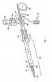
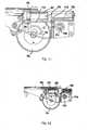
- Fig. 1shows a simplified schematic illustration of a biopsy device incorporating features of the present invention.
- the deviceincludes biopsy needle 108 comprising a hollow needle 50, in which there is arranged a longitudinally movable tissue sample-receiving device 52.
- the sample-receiving devicecomprises a tapered distal tip 54 and a cavity or canoe 56 for receiving a tissue sample.
- the sample-receiving devicecomprises a vacuum port 58, which is in fluid communication with the canoe 56 to allow tissue to be sucked into the canoe once the canoe is placed at a suspect site within the body of a living being. Vacuum is provided by a vacuum pump (not shown).
- a distal end portion of the hollow needle 50provides a circumferential cutting edge 60 for severing the tissue sample sucked into the canoe 56.
- the devicecomprises a spring-loaded firing mechanism, which in Fig. 1 is schematically illustrated by a spiral spring 62, the firing mechanism being arranged to displace the hollow needle 50 in a forward (distal) direction to sever the tissue sample sucked into the canoe 56.
- a sample flushing chamber 109from which the severed tissue sample in the canoe 56 can be ejected into a sample container 64.
- the sample-receiving device 52 with the canoe 56is retracted from a first extended position, in which the canoe 56 projects from the distal end of the hollow needle 50 as shown in Fig. 1 , to a second retracted position, in which the canoe 56 is aligned with upper and lower openings in the sample flushing chamber 109.
- a flushing liquidsuch as saline, is applied to eject the tissue sample from the canoe 56 into the sample container 64, the flushing liquid being conveyed from a liquid container 114 via a hollow liquid transport member or tube 116 by the aid of a peristaltic pump 118.
- a transport devicecomprising a bendable elongate element 66 in the form of a bendable bar or wire.
- a lower surface of the bendable bar or wireis toothed, so that it may engage a rotatable gear wheel or pinion 68 arranged to longitudinally displace the bar or wire 66 to thereby move the sample-receiving device 52 backward and forward in the hollow needle 50.
- a motor 70is provided to impart a driving force on the gear wheel or pinion 68, and a guiding wheel 72 is provided to stabilize the bendable, flexible bar or wire 66.
- a colling device 74for the bar or wire 66.
- the biopsy device schematically illustrated in Fig. 1is operated as follows: initially, the sample-receiving device 52 and the hollow needle 50 are arranged, such that the sample receiving cavity or canoe 56 is covered by the hollow needle 50, i.e. such that the outer surface of the tapered distal tip 54 of the sample-receiving device 52 forms a tapered distal continuation of the outer surface of the hollow needle 50.
- the needle 108is caused to penetrate body tissue of a patient, for example through manual insertion into the patient's body by a physician.
- the hollow needle 50is retracted to the position shown in Fig.
- Movement of the sample-receiving deviceis caused by rotating the gear wheel 68 in a clockwise direction, the gear wheel 68 engaging the flexible bar or wire 66, which in turn is attached to the sample-receiving device 52.
- a flow of flushing liquidis forced to pass through the sample flushing chamber to eject the tissue sample from the canoe into the sample container 64.
- the flow of flushing liquidis interrupted, and the gear wheel 68 is rotated counter clockwise to cause the flexible bar or wire 66 to be displaced in a distal direction, whereby the sample-receiving device 52 is pushed back to its first extended position.
- the above described cycle including tissue sample harvesting and ejectionmay then be repeated one or more times to obtain several tissue samples without retracting the hollow outer needle 50 from the suspect site in the body.
- the elements provided at the proximal end of the biopsy device shown in Fig. 1i.e. the firing mechanism including spring 62, gear wheel or pinion 68, motor 70, guiding wheel 72, coiling device 74, optionally the sample container 64, sample flushing chamber 109, liquid container 114, tube 116, pump 118, and vacuum pump (not shown) may be conveniently integrated in a handle unit as elaborated in the below-appended description of embodiments of the invention.
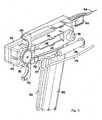
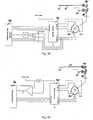
- Fig. 2is an exploded view of an embodiment of a biopsy device according to the present invention.
- the devicecomprises a left cover part 100 and a right cover part 102 and, interposed between the cover parts, a gear chassis unit 104 and a disposable unit 106 including a biopsy needle 108 and a sample flushing chamber 109.
- a first firing mechanism 110for firing the biopsy needle in a first mode as explained in detail below.
- the first firing mechanism 110forms an integrated unit, which is optional in the present biopsy device.
- the gear chassis unit 104includes a second firing mechanism 112 for firing the biopsy needle in a second mode as explained in detail below.
- the right cover part 102is formed to accommodate a flushing system for conveying liquid to the disposable unit 106 in order to eject a body tissue sample from the sample flushing chamber 109.
- the flushing systemincludes a liquid container 114, to which there is connected a hollow liquid transport member or tube 116, the tube defining a bent portion 117.
- a peristaltic pump 118for engaging the bent portion 117 of the tube 116.
- the left and right cover parts 100, 102, the gear chassis 104 and the flushing system 114-122forms a handle unit 105, to which the disposable unit 106 is releasably securable.
- a locking knob 124comprising an internal bushing 126 is provided to releasably secure the disposable unit 106 to the handle unit 105.
- the liquid flushing systemis disclosed further in Figs. 3-6 .
- indentations 128, 130see Fig. 2
- 132for receiving the liquid container 114, the peristaltic pump 118 and the tube 116, respectively.
- a pair of projections 134is provided at upper and lower edge portions of indentation 128 to secure the container in the indentation 128.
- the liquid container 114 and the tube 116are disposable elements, which an operator of the biopsy device may exchange on a regular basis. Exchange of these elements do not require removal of the pump 118, which normally remains attached to the right cover part 102 during exchange of the container 114 and tube 116.
- Fig. 4illustrates the container 114 and the tube 116 accommodated in the right cover part, with the bent tube portion 117 adequately placed around the circumference of the pump 118.
- the jaws 120 and 122are open, whereas in Fig. 5 , the jaws are partially pivoted to their closed position, and in Fig. 6 the jaws 120, 122 are fully pivoted to their closed position, in which they keep the bent tube portion 117 in close contact with the pump 118.
- tube 116When the container 114 and tube 116 are thus mounted in the right cover 102, the free end of tube 116 is connected to a conduit in the disposable unit 106 (cf. Fig. 2 ) for providing a fluid path from the container 114 to the sample flushing chamber 109 of the disposable unit.
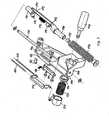
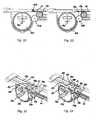
- the first firing mechanism 110 generally illustrated in Fig. 2will now be further described with reference to the exploded view of Fig. 7 .
- the firing mechanism 110is arranged to fire the sample-receiving device 52 and the outer needle 50 of the biopsy device substantially simultaneously. Referring back to Fig. 1 , the sample-receiving device 52 and the outer hollow needle 50 may thus be fired substantially simultaneously.
- Such simultaneous firingis useful for penetrating a suspect tissue mass, e.g. a tumour, penetration of which may be difficult due to e.g. hardness or due to a loosely supported attachment of the suspect tissue mass to surrounding tissue of the body.
- the loosely supported attachmentmay cause the suspect tissue mass to displace by pressure from the tip of the biopsy needle and to slide past the suspect tissue mass without penetrating it.
- the mechanismcomprises a primary axle 136 extending longitudinally through and parallel to a longitudinal axis of compression spring 138 and through a glider 140.
- a double shot frame 142supports the spring 138 and the glider 140 between opposing wall sections 144, 146. This is also visible in Fig. 2 , from which it is also apparent that the free end 141 of glider 140 extends into the disposable unit 106 through opening 107, the free end 141 engaging a yoke 182 (cf. Fig. 13 ), which in turn engages a needle driver 111 fixed to the outer surface of hollow needle 50.
- a solenoid 148extends through the frame, on the opposing side of which the solenoid extends through a nut 150, compression spring 152 and into solenoid holder 154.
- the solenoid holder 154engages a double shot lever 156 via a solenoid-connector axle 158 extending through the lever 156 and into the solenoid holder 154.
- An upper pivot pin 160 for the lever 156is pivotally supported relative to the frame 142 and extends through frame projection 162, whereby solenoid 148 may cause the lever 156 to pivot around pivot pin 160.
- the double shot mechanism 110further comprises a sliding rail 164, a sliding pawl 166, a spring pawl 168, and an impart member 170.
- Two through-going passagesare provided in the impart member 170, a first passage 172 for the solenoid-connector axle 158, and a second passage 174 for the primary axle 136.
- An impart member return spring 173is provided between the impart member 170 and a distally facing surface 143 of the glider 140.
- Fig. 8includes structure of the biopsy device, which contributes to the double shot, i.e. substantially simultaneous firing of the outer, hollow needle 50 and the sample-receiving device 52.
- the double shot firing mechanism 110illustrated in exploded view in Fig. 7 , is assembled and mounted to the gear chassis unit 104 (cf. Fig. 2 ), the gear chassis unit 104 also supporting the disposable unit 106.
- the gear chassis unitis only partially shown for the sake of clarity.
- a motor-driven, toothed trigger wheel 176is provided for causing compression of the compression spring 138 (cf. Fig. 7 ) as explained below with reference to Figs. 11-17 .
- the lever 156has two positions, an angled position as shown in Fig. 9 , and a vertical position as shown in Fig. 10 .
- the lever 156is normally biased towards the angled position of Fig. 9 by the compression spring 152, the compression spring 152 being omitted in Figs. 9 and 10 for the sake of clarity.
- an appropriate inputis provided to an electronic control system of the biopsy device, e.g. via a keypad on an external surface of the cover 100, 102 (cf. Fig. 2 ) .
- the double shot actioncommences by activation of the solenoid 148 to pivot the lever 156 around the upper pivot pin 160, whereby the lever is pivoted from the angled position of Fig. 9 to the vertical position of Fig. 10 .
- the trigger wheel 176is rotated in the direction of arrow 178.
- a first bearing element 180 protruding from a surface of the trigger wheel 176contacts the impart member 170, whereby the impart member 170 is displaced in the distal direction along the solenoid-connector axle 158.
- the stroke of the impart member 170is defined by sidewalls of the lever.
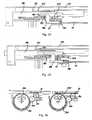
- the loaded firing mechanismis illustrated in perspective view in Fig. 13 .
- Compression spring 138is loaded, and a yoke 182 has been moved to a proximal, i.e. retracted position shown in Fig. 13 .
- the yoke 182is connected to the glider 140 via a forcing pin 202 (cf. Fig. 18 ) engaging an indentation formed in the free end 141 of the glider 14, and the yoke 182 engages the needle driver 111, whereby rotation of the trigger wheel 176 in the direction of arrow 178 (cf. Fig. 11 ) causes the yoke 182 as well as the needle driver 111 and the outer needle 50 to be proximally displaced.
- the outer, hollow needlemay thus be moved from its first extended position shown in Fig. 8 to its second retracted position of Fig. 13 .
- the yoke 182defines a recess 184, in which there is accommodated a slider 186, the slider 186 having an outwardly protruding centre piece 188.
- the centre piece 188is forced downwardly to engage the bendable elongate element 66, which is secured to the sample-receiving device 52.
- the required downward movement of the centre piece 188is caused, as the centre piece 188, during proximal movement of the yoke engages an engagement member (not shown), which may, e.g. form part of a housing (not shown).
- an engagement member(not shown)
- the centre piece 188is likewise displaced proximally, and in turn the bendable element 66 and the sample-receiving device 52 are moved along with the centre piece 188 of slider 186.
- the bendable element 66comprises a toothed flexible wire or flexible rack, which is driven by an advancing gearwheel 190 (cf. Fig. 19 ) engaging teeth of the toothed flexible wire 66.
- rotation of the gearwheel 190may cause the bendable elongate element 66 and the sample-receiving device 52 to be distally or proximally displaced, depending on the rotational direction of the gearwheel 190.
- a supporting roll 192is provided for stabilizing the flexible wire 66, i.e. to prevent it from flexing upwardly, when it is moved in a distal direction to push the sample-receiving device 52 in the distal direction.
- the bendable elongate element 66is made from Nylon 6-6.
- the bendable elongate elementmay have a generally circular cross section with flattened upper and lower surfaces, so that the element forms a wire with flat upper and lower surfaces and arc-shaped right and left surfaces.
- the diameter of the elementmay be approximately 1.2 mm, with a cross-sectional dimension between the flattened upper and lower surfaces being approximately 0.85 mm.
- the outer needle 50has an outer diameter of approximately 2.1 mm and an inner diameter of approximately 1.8 mm, the outer diameter of the sample-receiving device 52 being, in that embodiment, approximately 1.8 mm, the inner diameter of the sample-receiving device being 1.5 mm.
- a spring biased release hatch 194defining a cam 196 engages a distally facing edge on the lower surface of the glider 140 as shown in Fig. 14 .
- the release hatch 194is not visible in Figs. 11-13 , as it is hidden behind the lever 156 and the trigger wheel 176.
- the release hatch 194is rotationally spring biased, such that the cam 196 slides along the lower surface of the glider 140, until the impart member 170 and thus the glider 140 have reached their proximal extremity.
- the spring 138is kept loaded, and hence the glider 140, the yoke 182, the needle driver 111, the outer needle 50, the slider 186, the toothed flexible wire 66 and the sample-receiving device 52 are prevented from moving in the distal direction.
- the firing mechanismis now ready to fire, i.e. to release spring 138 to substantially simultaneously fire the outer needle 50 and the sample-receiving device 52.
- FIG. 16 and 17show the device from a side opposite to the side viewed in Figs. 11-15 .
- the distal end of the deviceis to the left in Figs. 16 and 17 .
- Rotation of the trigger wheel 176 in the direction of arrow 178 (cf. Fig. 11 )is now resumed, the trigger wheel thus rotating counter clockwise in Figs. 16 and 17 .
- a second bearing element 200 attached to the trigger wheel 176now contacts a proximal portion of the release hatch 194, and the release hatch is thus caused to rotate clockwise in Figs. 16 and 17 (counter clockwise in Fig. 14 ).
- the cam 196 of the release hatch 194moves downwardly, whereby its abutment against the glider 140 is released.
- the compression spring 138is consequently released as illustrated in Fig. 17 , and the double shot is fired.
- the compression spring 138 for the double shotis compressed by 20-25 mm during loading of the double shot mechanism as described above, corresponding to a 20-25 mm movement of the needle 50 and the sample-receiving device.
- the needle 50 and the sample-receiving device 52have been displaced 20-25 mm in the distal direction between the two positions shown in Figs. 16 and 17 , respectively.
- the disposable unit 106includes a driving gearwheel 204 for the toothed flexible wire 66.
- a cross-shaped driving axle 206projects from a side surface of the driving gearwheel 204, the cross-shaped driving axle 206 engaging a correspondingly shaped member in the gear chassis 104 (cf. Fig. 2 ).
- the gear chassis 104includes a motor for providing a driving force to the cross-shaped driving axle 206.
- the driving gearwheel 204is arranged to drive an first intermediate gearwheel 208, which in turn is arranged to drive a second intermediate gearwheel 209, which drives the advancing gearwheel 190, the advancing gearwheel being arranged coaxially with the second intermediate gearwheel 209 in a plane adjacent the plane of the second intermediate gearwheel, whereby appropriate engagement portions are provided at opposing surfaces of the second intermediate gearwheel 209 and the advancing gearwheel 190.
- These engagement portionsprovide a releasable interconnection, so that, before the double shot is fired, the second intermediate gearwheel 209 is brought out of engagement with the advancing gearwheel 190. This disengagement is caused by an arm 191 forming part of the yoke 182, which consequently moves with the yoke.
- a proximal section 67 of the toothed flexible wire 66is widened and includes a recess 69 for engagement by a flange portion 189 of the slider 186's centre piece 188.
- the housing element 210 shown in Fig. 18houses a helical coiling-up groove for accommodating the toothed flexible wire 66 when the sample-receiving device 52 is retracted to its second retracted position, in which the canoe 56 is aligned with the flushing chamber 109 (cf. Fig. 2 ).
- the centre piece 188 of the slider 186is lifted out of engagement with the widened proximal end portion 67 of the toothed flexible wire 66.
- the toothed flexible wire 66may be moved by providing a driving force to the cross-shaped driving axle 206 by an appropriate electrical motor (not shown), which advantageously may be integrated in the gear chassis 104.
- the yoke 182has been partly retracted as described above with reference to Figs. 9-13 , which has caused the centre piece 188 to engage the widened proximal end portion 67 of the toothed flexible wire 66.
- a first yoke arm 183engages a recess 113 in the needle driver 111
- a second yoke arm 187engages a recess 185 in the slider 186, cf. also the top views of Figs. 24 and 25 .
- the second intermediate gearwheel 209(cf. the above description of Fig. 19 ) is brought out of engagement with the advancing gearwheel 190 as illustrated in Figs. 24 and 25 , the second intermediate gearwheel 209 engaging the advancing gearwheel 190 in Fig. 24 and being out of engagement in Fig. 25 . Accordingly, the driving gear mechanism for the flexible toothed wire 66 causes no resistance to the loading and releasing of the double shot firing mechanism.
- the advancing gearwheel 190is kept in engagement with the wire 66 during loading and firing in order to stabilize the wire 66, i.e. to prevent flexing thereof.
- the first intermediate gearwheel 208(cf. Figs. 20-23 ) may advantageously be decoupled from the advancing gearwheel 190 in order to reduce resistance.
- Figs. 25 and 26generally depict a locking mechanism 220 for locking the driving gearwheel 204 when the needle 50 is loaded for a single shot, cf. the description of Figs. 27-31 below.
- a locking mechanism 220for locking the driving gearwheel 204 when the needle 50 is loaded for a single shot, cf. the description of Figs. 27-31 below.
- the second firing mechanismwhich causes the outer needle 50 with its distal circumferential cutting edge 60 (cf. Fig. 1 ) to be fired in the distal direction to sever a body tissue in the canoe 56 will now be further described with reference to Figs. 27-31 . It will be understood that only the outer needle 50 is fired, the sample-receiving device 52 remaining unaffected by firing of the second firing mechanism 112. This firing of the outer needle 50 will be referred to as "single shot” below.
- the trigger wheel 176 described above with reference to the double shotis also used in the single shot. In Fig. 27 , the trigger wheel 176 is in the same position as depicted in Fig. 11 .
- the trigger arm 304forms a fork 308 engaging an transmission element 310, a proximal end of which abuts a distal end of the compression spring 62, and a distal end of which is connected to the needle driver 111 via a pivotally mounted element 312.
- the element 312is pivotally mounted to a sliding support member 314 secured to the compression spring 62, and it is upwardly spring-biased to the inclined position shown in Figs. 27 and 28 .
- the sliding support member 314is connected to the trigger arm 304 via a connector 313 integral with the transmission element 310.
- the trigger arm 304Upon further rotation of the trigger wheel 176, the trigger arm 304 is rotated around its pivot 306, as the third bearing element 300 imparts the impart cam 302 of the trigger arm 304, cf. Fig. 29 . Consequently, the compression spring 62 is compressed, as a proximal end of the spring is appropriately supported. It will be appreciated that in the position of Fig. 29 , the outer needle 50 has been retracted, whereby the canoe 56 of the sample-receiving device 52 (cf. Fig. 1 ) is laid bare distal to the distal end portion of the outer needle 50. The position of Fig. 29 thus corresponds to the position of Fig. 1 .
- the single-shot firing mechanism 112is further illustrated in the exploded view of Fig. 31 .
- a supporting axle 316extends through the compression spring 62 and is supported proximally thereof by a bushing 318 and a lock washer 320.
- a distal end of the supporting axle 316extends through the sliding support member 314, in which it is supported by a pair of bushings 322.
- a pivot pin 315is provided for the pivotable element 312.
- a biasing mechanism 324is mounted to the trigger arm 304 via a spring element 326, one end of which is fixed in engagement grooves 328 provided on the trigger arm 304.
- a compression spring 336is provided to bias the pivotable element 312 towards an upwardly inclined position, in which it is in contact with a proximal surface of the needle driver 111 (cf. Figs. 27-30 ).
- rotation of the trigger wheel 176causes loading and firing of the single-shot firing mechanism for severing a body tissue sample, which is now collected in the canoe 56 of the sample-receiving device 52 (cf. Fig. 1 ). Further rotation of the trigger wheel 176 causes movement of the bendable elongate element 66 (cf. Figs. 1 and 19-23 ) in the proximal direction to move the canoe 56 from its first extended position, in which it is accommodated in the distal end portion of the hollow needle 50, to its second retracted position, in which it is aligned with the flushing chamber 109 (cf. e.g. Figs.
- a drive wheel 340which forms a toothed arc portion 342 and a connecting portion 344.
- a free end of the connecting portion 344is pivotally mounted to a roller 346, which may slide in a curved track 348 formed in a carrier plate 350.
- the drive wheel 340is rotationally supported at a centre point 352 of the toothed arc portion 342. It will be understood from Fig.
- the drive wheel 340is connected to the trigger wheel 176 via the rotational support at 352, at which the drive wheel 340 is connected to a cam washer 354 forming a notch 356 for engagement with a reduced diameter portion 347 of the roller 346.
- the cam washer 354engages a circular element 358 secured to the trigger wheel 176.
- the gear drivewhich is partly visible in Fig. 36 , comprises a first gearwheel 360, which is engaged by the toothed arc portion 342 of the drive wheel.
- the first gearwheel 360drives a second gearwheel 362.
- An axle 364 for the first gearwheel 360is mounted in a first sleeve 366, and an axle 368 for the second gearwheel 362 extends through a cross-shaped reinforcement member 369 and engages a connector 370, which provides a driving force transmission interconnection to the driving gearwheel 204 (cf. Figs.
- the disposable unit 206also accommodates the bendable elongate element 66 for moving the sample-receiving device 52 in the hollow needle 50 ( Fig. 2 ), the flushing chamber 109, and the coiling device 74 ( Fig. 35 ) for coiling up the bendable elongate element 66.
- the driving gearwheel 204which is omitted in Fig. 35 in order not to cover the coiling device 74, drives the intermediated gearwheel 208 and the advancing gearwheel 190, which in turn engages teeth of the bendable elongate element 66.
- the bendable elongate element 66When the bendable elongate element 66 is moved in the proximal direction to retract the sample-receiving device for ejection of the harvested tissue sample, the bendable elongate element is coiled into the coiling device 74 forming a spiral, which allows the bendable elongate element 66 to be wound up and unwound in a controlled manner.
- the gear chassis 104(cf. Fig. 2 ) includes further elements shown in Fig. 36 .
- a driving motor 372is provided for driving the trigger wheel 176 via a gear drive 374.
- a further motor 376is provided for driving the peristaltic pump 118 (cf. Figs. 2-6 ) for sample ejection by liquid flush via a spindle 377 and gearwheels 378 and 379.
- a glide bushing 380is provided for the connector 370 to receive the disposable unit 106 in the handle unit 105 (cf. 2).
- a vacuum pump 382is provided for creating vacuum suction to suck body tissue into the canoe 56 of the sample-receiving device 52 (cf. Figs. 1 and 2 ), the vacuum pump 382 being in fluid communication with the canoe 56 via appropriate tubes (not shown) and the vacuum port 58.
- Fig. 37shows the cycle of the movement of the trigger wheel described in relation to Figs. 28-34 and back.
- the trigger wheelrotates approximately 290° to the position of Fig. 34 .
- S-1corresponding to the rotation of the trigger wheel 176 from the position of Fig. 28 to the position of Fig. 29
- the compression spring 62is compressed.
- S-2the third bearing element 300 looses contact with the upright impart cam 302, thereby unloading the spring 62.
- the trigger wheel 176has now rotated the cam washer 354 (cf. Fig. 36 ) to the position, in which the notch 356 engages the roller 346.
- the trigger wheel 176rotates further to move the drive wheel 340 from the position of Fig. 32 to the position of Fig. 34 to thereby pull the sample-receiving device 52 backwards to its second retracted position, in which the canoe 56 is aligned with the flushing chamber 109 for ejection of the severed tissue sample collected in the canoe 56.
- Rotation of the trigger wheel 176is now reversed, as indicated by block arrows in Fig. 37 .
- the trigger wheel 176moves the drive wheel 340 back from the position of Fig. 34 to the position of Fig. 32 to thereby move the sample-receiving device 52 to the distal end portion of the outer needle 50, i.e. to the first extended position of the sample-receiving device.
- the sample-receiving device 52is now at its distal extremity, and the notch 356 of the cam washer 354 (cf. Fig. 36 ) disengages the roller 346.
- a final segment of the reverse rotation of the trigger wheel 176, S-6,is an idle run, in which the trigger wheel 176 is moved from a position approximately equal to the position of Fig.
- the third bearing element 300contacts and passes the impart cam 302, which is biased in the proximal direction by the spring element 326 (cf. Fig. 31 ). If a further tissue sample is to be severed, the above cycle may now be repeated.
- Fig. 38that segment of the rotation of the trigger wheel 176, which causes the double shot described above with reference to Figs. 9-17 , is added to the S-1 - S-6 rotation segments shown in Fig. 37 .
- D-1a first rotation segment
- the trigger wheel 176is rotated from the position of Fig. 11 to the position of Fig. 12 to compress the compression spring 138 (cf. e.g. Fig. 12 ).
- D-2the compression spring 138 is unloaded to substantially simultaneously fire the outer needle 50 and the sample-receiving device 52, i.e. to move the trigger wheel from the position of Fig. 16 to the position of Fig. 17 .
- the S-1 - S-6 rotation segmentsare now performed as described above with reference to Fig. 37 .
- the trigger wheel 176is rotated from a position, which is slightly upstream of the position depicted in Fig. 12 (the trigger wheel rotating counterclockwise in Fig. 12 ), to the position of Fig. 11 .
- the solenoid 148cf. Figs. 9 and 10
- the impart member 170is not in the plane of the first bearing element 180 (cf. Figs. 11 and 12 ), so that bearing element 180 may pass freely to the position of Fig. 11 without contacting the impart member 170.
- control system of the biopsy deviceis configured such that a double shot sequence is automatically followed by a single-shot sequence.
- the double shotmay be activated without incurring a single-shot sequence.
- the operation of the deviceincluding activation of the double- and single-shot sequences described above with reference to Figs. 9-35 , and activation of ejection flushing, may be controlled by an operator via an appropriate touch-pad system provided e.g. on an exterior surface of the handle unit 105 (cf. Fig. 2 ).
- controlling of the movement of the needle 50 and the sample-receiving device 52is widely based on mechanical means, except for certain electronically controlled elements, such as the solenoid 148 (cf. e.g. Figs. 9 and 10 ), the motor 372, vacuum pump 382 ( Fig. 36 ) and the peristaltic pump 118 for liquid flushing for tissue sample ejection.
- the control systemmay incorporate further electronic elements.
- the double- and single shot firing mechanismsmay be driven by separate motors, which are electronically controlled, and loading and firing of the first and second mechanisms for single and double shot, respectively, may incorporate electronically controlled elements for causing appropriate engagement and disengagement of various parts.
- Figs. 39 and 40illustrate two alternative embodiments of the control system for determining the distance between the first extended position of the sample-receiving device 52 and its second retracted position, e.g. to provide automatic detection of the length of the outer hollow needle 50.
- the control systemuses a microcontroller 400 to constantly monitor the rotation of the motor unit 372 of the handle unit 105. Simultaneously herewith, the system monitors, by means of an appropriate position sensor 371 (cf. Fig. 36 ) the position of one of the transmission axles that are part of the gear system translating the movement from the motor unit to the bendable elongate element 66.
- the position of the bendable elongate elementmay be known at all times, and the system may configure itself according to the length of the bendable elongate element, and thus to the length of the outer needle 50 (cf. e.g. Fig. 2 ).
- the embodiment in Figs. 39 and 40includes three sensors that are connected directly to the motor unit 372 in the handle unit 105, and which record the rotation of the motor, cf. Fig. 39 .
- These sensorsmay be of the Hall sensor type or of a similar type, and their output is fed into a motor driver unit 402 and a microprocessor 400.
- the motor unit 372When the motor unit 372 is activated and starts rotating, movement is translated from the motor to the bendable elongate element 66. As long as the bendable elongate element is free to move within the lumen of the outer hollow needle 50, a steady stream of pulses are fed from the Hall sensors to the motor driver 402 and the microprocessor 400.
- the bendable elongate elementreaches the end of its movement spectrum, it arrests the motion of the motor 372 and breaks the steady stream of pulses from the sensors. This cease of impulses is recorded by the microprocessor 400.
- the microprocessor 400may record the position of the aforementioned transmission axle.
- Information about the position of the transmission axlemay be provided by a potentiometer mounted on the transmission axle.
- a DC signal obtained from a wiper of the potentiometermay reflect the instantaneous position of the transmission axle and the entire movement spectrum of the bendable elongate element 66 corresponding to an angle of rotation of 300 degrees.
- the microprocessor 400may reduce the wear on the motor by gradually reducing its speed and stopping it immediately prior to reaching the position corresponding to the second retracted position of the bendable elongate element 66.
- An alternative or complement to measuring the rotation of the motor 372 directlyis to measure motor current passing through the motor. Results of this measurement may be transmitted to a microcontroller or microprocessor wherein a suitable microprocessor program or software comprises a pre-defined current threshold. This measurement of motor current may be done with a sampling A/D converter integrated with the microcontroller or a corresponding external device. As long as the bendable elongate element 66 is free to move within the lumen of the outer hollow needle 50, the load on the motor is substantially constant, and thus the motor current is also constant. When the load increases because the rod or rack has reached either end of its movement spectrum, the motor current increases.
- the current changeis recorded by a motor driver unit that is an integrated part of the control system.
- the microcontrollermay record the position of the transmission axle.
- Information about the position of the transmission axlemay be provided by a suitable electrical or optical signal derived from e.g. a potentiometer.
- a third means of transmitting information about the length of the bendable elongate element 66 to the microcontrolleris to use a mechanical means, such as a spring-loaded pin that slides into a recess in the bendable elongate element 66 or the sample-receiving device 52. Also optomechanical means may be utilized.
Landscapes
- Health & Medical Sciences (AREA)
- Life Sciences & Earth Sciences (AREA)
- General Health & Medical Sciences (AREA)
- Public Health (AREA)
- Biomedical Technology (AREA)
- Heart & Thoracic Surgery (AREA)
- Medical Informatics (AREA)
- Molecular Biology (AREA)
- Surgery (AREA)
- Animal Behavior & Ethology (AREA)
- Pathology (AREA)
- Engineering & Computer Science (AREA)
- Veterinary Medicine (AREA)
- Sampling And Sample Adjustment (AREA)
- Apparatus For Radiation Diagnosis (AREA)
- Length Measuring Devices With Unspecified Measuring Means (AREA)
- Devices For Conveying Motion By Means Of Endless Flexible Members (AREA)
- Medicines Containing Antibodies Or Antigens For Use As Internal Diagnostic Agents (AREA)
- Analysing Materials By The Use Of Radiation (AREA)
- Investigating Or Analysing Biological Materials (AREA)
- Inorganic Compounds Of Heavy Metals (AREA)
- Bakery Products And Manufacturing Methods Therefor (AREA)
Abstract
Description
- The present invention relates to a biopsy device for harvesting tissue samples of human or animal bodies. The invention is particularly, but not exclusively, aimed at percutaneous biopsy, in which it is desirable to gain access to suspect tissue mass in a minimally invasive manner. The invention is particularly concerned with aspects of conveying a sample-receiving device containing one or more harvested tissue sample in an outer hollow needle of the biopsy device.
- For diagnostic purposes it may be desirable to obtain a tissue sample of a human or animal body for in vitro cytological and/or histological examination. Tissue sampling may be performed either as an open or a percutaneous technique. In the open technique, either the entire suspect mass (excisional biopsy) or part of the suspect mass (incisional biopsy) is removed. Access to the lesion as well as removal is generally obtained with the use of scalpels, and open biopsies are a reliable - if quite invasive - means of obtaining tissue samples.
- In the percutaneous technique, a needle is used to gain access to the suspect tissue mass in a less invasive fashion. This needle may be hollow, permitting the aspiration of single cells and tissue fragments into a lumen by application of a vacuum (aspiration biopsy). Alternatively, larger tissue cores may be harvested by means of a needle containing an inner movable trocar with a notch formed to receive tissue cores, and an outer, slidable cannula with a sharpened distal end used to sever these cores from the surrounding tissue (core needle biopsy). By advancing the inner trocar into a suspect lesion and subsequently advance the outer slidable cannula to cover the notch completely, a tissue sample may be severed and held in the notch. The needle may then be retracted from the body of the patient, and the tissue sample may be collected and stored for further analysis.
- Core needle biopsy devices have been preferred tools among physicians due to their simple use and versatility. The core needle devices may be applied to a broad range of different tissues and different anatomical locations, and provide the pathologist with samples suitable for histological analysis for the accurate diagnosing and staging of suspect masses.
- Obtaining the largest possible sample size is an important objective in the harvesting of core tissue samples. Prior art biopsy systems have used vacuum to engage and draw tissue towards the notch or tissue-receiving chamber or basket of the biopsy device prior to cutting. Thus, tissue sample sizes may be significantly increased with a given biopsy needle diameter or larger samples extracted with the same needle diameter to improve diagnostic accuracy.
- Another well-known prior art technique to increase sample size is to harvest multiple samples in order to obtain sufficient tissue for a reliable diagnosis. To do so with the aspiration, core needle biopsy devices or single-action vacuum-assisted devices is only possible through multiple device insertions, resulting in increased patient discomfort, time consumption and risk of bleeding.
- In the area of breast biopsies, this problem has been solved with the development of biopsy systems enabling the operator to extract multiple samples with a single biopsy device insertion. These biopsy devices generally apply vacuum to engage and aspirate a suitable amount of tissue into a hollow portion of the instrument. The power and vacuum supply units pertaining to those multiple biopsy devices are housed in separate vacuum stations that require carts for transportation as well as hoses and leads to function properly. The physical connection between the biopsy device and the accompanying vacuum/power supply units means that the freedom of movement of the operator or physician is limited, and auxiliary devices furthermore take up storage and floor space.
- In prior art biopsy systems and devices tissue sample extraction, ejection and subsequent storage of the individual tissue samples have been accomplished by a number of different methods. Some biopsy devices comprise mechanical extraction and ejection of extracted tissue samples, as illustrated in
US 5,526,822 , which forms the basis for the preamble of appendedclaim 1. The biopsy device captures and holds the tissue sample in a lumen of an inner, rotating cutting cannula that is retractable to a point outside the anatomy of the patient. An ejector pin is utilized to push the captured tissue sample out of the lumen of the cannula. - Other prior art biopsy devices feature vacuum-driven extraction and ejection of tissue samples.
US 6,638,235 discloses a biopsy device with an inner, rotating cutting cannula capable of harvesting multiple tissue samples in a single cannula insertion. The device reduces operator involvement by enabling the automatic extraction and collection of multiple tissue samples in a collection chamber placed outside the anatomy of the patient. Tissue samples are extracted from the point of sampling and moved through the inner lumen of the cutting cannula to the collection chamber by means of a vacuum that is drawn through the collection chamber and the inner lumen of the cutting cannula. US 5,236,334 describes a biopsy needle unit comprising an outer hollow needle and a sample receiving device for insertion therein. The arrangement is for insertion in a biopsy gun. A further biopsy arrangement is shown inUS 4,907,598 in which a receiving device in a hollow needle is displaced by means of a flexible cable connected to a handle portion including a push button for controlling the cable.- In the sampling, collection and storing of some types of tissue samples, such as prostate tissue samples, it is desirable that extracted individual tissue cores or samples are kept apart if a subsequent diagnosis is to be valid.
- It is an object of preferred embodiments of the present invention to provide a biopsy device that may permit sampling, preferably in an automatic manner. It is a further object of preferred embodiments of the invention to provide a biopsy device, which allow for convenient penetration of suspect tissue mass. It is a still further object of preferred embodiments of the invention to provide a biopsy device, which allow for convenient severing of a tissue sample. It is a still further object of preferred embodiments of the invention to provide a biopsy device, which facilitate handling of acquired tissue samples by a physician. It is a still further object of preferred embodiments of the invention to provide a biopsy device, which is conveniently manoeuvrable by a physician. It is a still further object of preferred embodiments of the invention to provide a biopsy device, which allow for storing of individually separated tissue samples in a preserving agent.
- The invention is defined in appended
claim 1. Preferred embodiments are described in the dependent claims. - In a first aspect, the invention provides a biopsy device for harvesting at least one tissue sample from a body of a living being, the device comprising:
- a hollow needle with a distal end portion adapted to be introduced into the body;
- a cutting mechanism for severing the at least one tissue sample;
- a sample-receiving device with a cavity for receiving the at least one severed tissue sample, the sample-receiving device being receivable in the hollow needle and movable therein;
- a transport device for moving the sample-receiving device in the hollow needle, the transport device comprising a bendable elongate element.
- The transport device (or transport mechanism) may be coupled with the cutting mechanism and a compact driver system featuring all necessary controls and mechanics. An optional vacuum supply unit for aspirating (or sucking) tissue into the cavity of the sample-receiving may either be integrated with a handle unit or it may be arranged in an external or freestanding unit. The transport mechanism preferably enables the collection and removal of multiple tissue samples in a fast, efficient and reliable procedure. The cutting mechanism preferably enables the instant and efficient severing of tissue samples. This may e.g. be accomplished with rotating cutters of spring-loaded mechanisms, although electro-cautery is also applicable. The handle unit comprises drivers that deliver the necessary actuation forces and motions to the transport and cutting mechanisms. This may e.g. be accomplished through several means, the most common being springs, electric motors or air-powered drives.
- The transport device of the present biopsy device includes any suitable system for moving the sample-receiving device in the hollow needle, i.e. any system capable of pulling the sample-receiving device from a first extended (i.e. distal) position to a second retracted (i.e. proximal) position and of pushing the sample-receiving device from the second retracted position to the first extended position. The transport device for moving the sample-receiving device in the hollow needle comprises a bendable elongate element, such as a steel wire, two or more twisted wires, such as a Bowden cable or any other flexible or bendable element. The elongate element is bendable away from the longitudinal direction of the hollow needle, i.e. laterally bendable, and it preferably has sufficient stiffness or sufficient support in lateral directions to prevent the bendable elongate element from flexing outwardly when the sample-receiving device is to be pushed from the second retracted position to the first extended position.
- A coiling device is provided for coiling up the bendable elongate element, the coiling device being preferably arranged at a proximal end of the device, such as at least proximal of the second retracted position. In embodiments, in which the bendable elongate element is comprised in a disposable unit, which is attachable to e.g. a handle-unit or a stationary unit of the biopsy device, the coiling device is preferably integrated in the disposable unit as elaborated in more detail below.
- The bendable elongate element may have a longitudinally extending portion of circular or non-circular cross section, such as e.g. polygonal cross-section, such as triangular or rectangular. A polygonal cross-section confers the possibility that the bendable elongate element may be toothed for engagement by a driving gearwheel. Thus, in one embodiment, the bendable elongate element comprises a row of regularly spaced teeth extending substantially perpendicularly to a longitudinal axis of the elongate element. In this embodiment, the biopsy device may have a rotatable gear wheel having a rim with teeth for interacting with the teeth of the elongate element so as to move the elongate element in the hollow needle along the longitudinal axis. One or more supports may be provided for supporting the bendable elongate element in the lateral direction to avoid flexing thereof, the support(s) comprising e.g. two opposing wall sections arranged with a mutual clearance corresponding to a thickness of the bendable elongate element, the bendable elongate element being free to slide in the longitudinal direction between the wall sections. Similarly, the bendable elongate element may slide between opposing roller elements.
- In order to allow the sample-receiving device to rotate relative to the bendable elongate element, the sample-receiving device may be secured or attached to the bendable elongate element by means of a swivel joint.
- From the above discussion, it will be appreciated that the sample receiving device may have a length, which is substantially shorter than a length of the hollow needle, and that a distal end of the bendable elongate element may be attached to a proximal end of the sample-receiving device, so that the bendable elongate element causes movement of the sample-receiving device in the hollow needle.
- It will also be understood that the biopsy device of the present invention comprises a handle unit with a power source and a motor for driving the transport device, and that the transport device, the hollow needle and the sample-receiving device are comprised in a disposable unit, which is releasably secured to the handle unit. A driving interface is preferably provided to transmit a driving force from the motor in the handle unit to the bendable elongate element in the disposable unit.
- The coiling device is likely to be contaminated by body tissue and/or body fluids during tissue sample harvesting, as the bendable elongate moves in the hollow needle, the inner wall of which may be in contact with the tissue sample, when the tissue sample is being moved In the cavity of the sample-receiving device. Thus, the coiling device is preferably comprised in the disposable unit. Irrespective of whether the coiling device is comprised In the disposable unit or in other parts of the biopsy device, such as in the handle unit, the coiling device may form a spiral. The spiral may e.g. be formed by at least one wall element, which is arranged such that contact between coiled-up portions of the bendable elongate element is prevented to avoid uncontrolled bending or varying dimensions of a coiled bendable elongate element?
- Embodiments of the biopsy device of the present invention, which form a handheld unit, also include the transport device, e.g. the bendable elongate element, in the handheld unit. It will be appreciated that the handle unit preferably is embodied as a hand held unit, which accommodates all required power, liquid and vacuum sources as well as possible driving mechanisms for needle and sample-receiving device and firing mechanisms, cf. below. Generally, the entire biopsy device of the present invention, including the hollow needle, the cutting mechanism, the sample-receiving device, the transport device, an optional liquid supply unit and all other structural elements mentioned herein may be comprised in a hand-held unit.
- Further embodiments and features will become apparent from the below description.
- Transfer of samples from the point or position of sampling (or harvesting site) to the point or position of collection (or sample ejection) is preferably carried out by means of a flat, toothed bar, preferably of a polymer material such as polypropylene, to which the sample-receiving device is attached, the sample-receiving device being e.g. in the form of a canoe-like container to hold tissue samples once they have been severed. The sample-receiving device may have a side-facing opening for receiving tissue samples, and may have one or several vacuum ports to enable the aspiration of tissue into the sample-receiving device by application of vacuum. Severing of tissue samples may be carried out by means of a coaxial, piston-like system comprising a spring-loaded outer cutting cannula (i.e. the hollow needle) with a sharpened distal end (i.e. the circumferential cutting edge) and capable of axial movement, and a an inner guiding cannula with a sharpened tip capable of penetrating tissue as the biopsy device is positioned in the tissue to be sampled. The inner guiding cannula may be non-movable or movable by the transport device described herein. The inner cannula may have a side-facing notch (or cavity) enabling tissue to prolapse into the inner lumen of the cannula and into the waiting sample-receiving device. The transport system for the sample-receiving device and/or for the severed tissue sample is axially movable within the inner lumen of the inner cannula, e.g. to advance and retract the sample-receiving device. Power for driving the transport mechanism may be delivered by an electric or pneumatic driver unit. Expelling of samples from the sample-receiving device and into a suitable transport container may be done by means of liquid or pressurized air at the point of collection (or ejection).
- The bendable elongate element may comprise a flat bar, toothed on one side, and it may be made from a suitable polymer material such as polypropylene or Nylon™. The bendable elongate element is moved longitudinally in the cannula system and enables the transport of tissue samples from the harvesting site at the distal tip of the biopsy device, e.g. the first extended position of the sample-receiving device, to the point of ejection, e.g. the second retracted position of the sample-receiving device. It may fit tightly to the wall of the inner cannula to ensure lateral stiffness once it enters the cannula. A cavity on the upper side may enable the application of vacuum to the distal end of the system. The distal point of the cannula system may feature an attachment device to enable the temporary coupling of the cannula with the suspect tissue mass, e.g. a tumour.
- The bendable elongate element (or bar) may be coupled with a sample-receiving device with a vacuum gate. This vacuum gate may have several different configurations, depending on the application and the design of the expelling (i.e. flushing) chamber. The flat toothed bar may establish a vacuum channel in the cannula. The sample-receiving device may receive the tissue during the sampling procedure and hold the sampled tissue on its way from the point of sampling or harvesting to the point of collection. A filter or grid may be provided to ensure that no tissue escapes the container.
- A coupling mechanism between the toothed bar and the sample-receiving device may permit a swiveling motion of the sample-receiving device relative to the flat bar as the sample-receiving device is readied for emptying (or ejection), to facilitate the emptying procedure.
- The toothed bar may interact with a pinion, allowing the conversion of rotational motion of the pinion to linear motion of the toothed bar to enable the withdrawal of harvested tissue samples and the positioning of the sample-receiving device in the cannula system, i.e. in the outer hollow needle. The pinion may be of metal or a ceramic material to ensure longevity.
- The motor for driving the sample receiving device or pinion may be an electric motor. Two batteries and a switch (on/off switch) may be provided for activating and driving the motor. The motor may be pneumatic, which may render the system MRI-compatible.
- The coiling device may comprise a spool-like component placed in the handle to enable the coiling-up of the toothed bar as it is retracted. Hereby the toothed bar will not protrude far beyond the proximal end of the transport mechanism. This is an advantage, in particular when taking biopsies at deep anatomical depths. Alternatively, the toothed bar can be bent away form its longitudinal direction.
- A guiding wheel may be incorporated to stabilize the flat bar and the sample-receiving device as the assembly is advanced into the cannula system.
- A driver unit of the biopsy device may comprise the following components: One or more motors integrated in a suitably designed handle. The motor may generally have two main functions, namely to advance and retract the flat, toothed bar with the sample-receiving device, and to cock and release the firing mechanism when a sample has been readied for cutting. The cocking of the cutting mechanism may result automatically once the system is put into operation, with the retraction, emptying and extension of the sample-receiving device automatically following the firing of the cutting mechanism. Control of the device may result e.g. from the depressing of a pedal or a selection of buttons. The driver unit may be either electrically or pneumatically driven, and it is preferably an independent, completely freestanding unit with its own power supply, vacuum-source and tissue collection container.
- It may be configured to enable (by selection) one or more of the following operation modes: stepwise, semi-automatic or fully automatic.
- The vacuum supply and the expelling mechanism may either be integrated parts of a handle housing the driver unit, or they may be placed in an external unit. The expelling mechanism (or ejection system) may utilize air pressure, water flushing or a third means of expelling the tissue.
- As an alternative to the toothed bar, a wire, e.g. a steel wire, may be used as a transport mechanism. The steel wire can be a single wire, or it can have two or more twisted wires, with or without a core wire, a principle known from the so-called Bowden cables. The Bowden cable may be coiled up as described above. To enable the functioning of such a wire, the spool used to coil up the wire may have a groove in its surface tailored to the dimensions of the wire, and the spool may be suspended in a tight-fitting housing unit, whereby a channel is formed for the wire. The use of a stiff wire, in combination with the tailored channel, enables the retraction and advancement of the sample-receiving device within the guiding cannula.
- In a default position of the biopsy device, the flat bar with the sample-receiving device may be maximally extended, and the sample-receiving device may be placed in the distal end of the cutting system. The outer cannula may be maximally extended, covering the tissue-receiving port in the inner cannula as the system is advanced into the body of the patient.
- When a sampling sequence is initiated, the driver unit may be activated to start cocking of a spring-loaded firing mechanism as described in more detail below, and the outer cannula may be pulled towards the proximal end of the device, opening the tissue-receiving port. Once the outer cannula has been retracted to open the tissue receiving port, a vacuum may be applied to the inner lumen of the inner cannula, sucking tissue into the tissue receiving port and into the sample-receiving device.
- After the cutting mechanism has been retracted, the sample taking mechanism may release the spring-loaded firing mechanism, rapidly advancing the outer cannula to sever the tissue sample. Upon severing of the tissue sample, the flat, toothed bar with the sample-receiving device may be retracted and carry the biopsy sample towards the point of collection (or ejection).
- A mechanism at the proximal end of the inner cannula may engage and swivel the sample-receiving device when it exits the inner cannula to facilitate the expelling (or ejection) of samples. As the sample-receiving device enters the expelling chamber, a stream of liquid may automatically be released to flush the tissue sample out of the sample-receiving device and into a suitable container. The flushing liquid is preferably saline, possibly containing additives for preserving the sample or preparing it for examination.
- Having completed the expelling cycle, the flat, toothed bar and the sample-receiving device are advanced, and the sample-receiving device may be positioned in the distal end of the inner cannula in preparation of a new cycle. On the completion of the sampling sequence, the outer cannula may be left in the default position to close the tissue receiving port in preparation of the removal of the biopsy needle. The tissue storage container may be detached from the biopsy device and sent to the pathologist for further analysis.
- A tip of the sample-receiving device may be conical, and it may be configured to serve as a penetration point, tissue-receiving port, sample container and a cutting board.
- In the present invention, the outer diameters of biopsy needles may be within the range from 0.5 mm to 5.0 mm, such as in the range from 1.2 mm to 3.0 mm. Biopsy needles are typically made of stainless steel, but other materials can be used such as titanium, which is MRI compatible.
- In order to accurately control movement of the sample-receiving device in the hollow needle, the sample-receiving device and the hollow needle may be shaped, so that relative rotational displacement between the sample-receiving device and the hollow needle in said plane is prevented. For example, the outer cutting cannula or hollow needle may comprise first orientation means adapted to co-operate with mating second orientation means of the sample-receiving device, so as to guide and orient the sample-receiving device in a plane substantially perpendicular to the axis of movement of the sample-receiving device inside the outer cutting cannula. The orientation means may ensure reliable positioning of a sample ejection aperture of the sample-receiving device in a plane substantially perpendicular to the axis of movement thereof, so as to support automated ejection of extracted tissue samples. For example, the oval cutting cannula and the sample-receiving device may have oval profiles, or an inward protuberance may be provided on an inner wall of the cutting cannula (outer needle), the protuberance engaging a corresponding groove in the sample-receivng device.
- The biopsy device of the present invention may comprise a liquid supply unit adapted to comprise a flushing liquid, the liquid supply unit being operatively connected to the cavity of the sample-receiving device through a hollow liquid transport member so as to allow tissue sample ejection by liquid flushing.
- The liquid supply unit as outlined above allows for cautious handling of the at least one harvested tissue sample during the biopsy procedure and subsequent retrieval of acquired tissue samples to maintain the structural integrity of suspect tissue and allow an accurate diagnosis to be made. Furthermore, individually extracted tissue cores or samples may advantageously be kept apart to enable better diagnostic capabilities. This is beneficial in respect of most kinds of tissue samples, such as prostate samples. In addition, liquid flushing to eject the at least one tissue sample from the cavity of the sample-receiving device allows for automated and rapid biopsy procedures with minimal patient trauma and minimal manual handling of the harvested tissue sample(s) by physicians.
- The flushing liquid is preferably a preserving agent, in which the harvested tissue sample is to be stored following ejection from the cavity of the sample-receiving device. The flushing liquid may e.g. comprise saline or formalin. It will be appreciated that no rough handling of the body tissue sample, e.g. by forceps, is required in order to remove the harvested tissue sample from the cavity of the sample-receiving device, as ejection may be caused solely under the action of the flushing liquid. The cavity may have a substantially circular cross-section. Particularly advantageous embodiments of the biopsy device of the present invention are completely handheld and include integral vacuum supply and liquid supply mechanisms as well as power source, thereby eliminating any need for separate (or external) vacuum, fluid and power sources. Alternatively, the vacuum supply and/or power source could be arranged externally to the biopsy device and connected thereto by suitable electrical power conductors and vacuum hoses.
- In one embodiment, the biopsy device of the present invention comprises a closed system for tissue-sample extraction and transportation to avoid leakage of bodily fluids, operator exposure to biohazards and contamination of extracted tissue samples. This embodiment ensures that manual handling of extracted tissue samples is minimized, and possible handling damage is consequently minimized.
- The hollow needle preferably defines a longitudinally extending annular body portion, which defines a co-extending longitudinal cavity in the hollow needle, and the cavity in the sample-receiving device may have a lateral opening for receiving the at least one tissue sample.
- In one embodiment of the present invention, the cutting mechanism comprises a circumferential cutting edge at the distal end of the hollow needle as described in more detail below. In order to allow efficient tissue severing by the circumferential cutting edge, the sample-receiving device and the hollow needle are preferably movable relative to each other, such that the sample-receiving device may be in a projecting position, in which it projects from a distal tip of the needle, and a retracted position, in which it is accommodated in the hollow needle, and in which the distal end of the device is defined by said circumferential cutting edge and possibly a tapered tip of the sample-receiving device.
- In order to aspirate or suck body tissue into the cavity of the sample-receiving device, the biopsy device of the present invention preferably comprises a vacuum pump for generating a suction effect in the cavity of the sample-receiving device, the vacuum pump being in fluid communication with the cavity of the sample-receiving device through a longitudinally extending passage in the sample-receiving device and/or through the longitudinally extending passage defined by the hollow needle. For example, there may be provided one or more vacuum ports at the bottom of the sample-receiving device, such as in a wall section defining a bottom of the cavity in the sample-receiving device, through which vacuum port(s) the cavity is in fluid communication with the interior of the hollow needle, which in turn is in fluid communication with the vacuum pump. Alternatively, there may be provided one or more vacuum ports in a side wall forming a side portion of the cavity in the sample-receiving device, through which vacuum port(s) the cavity may be in fluid communication with the interior of the hollow needle or with a longitudinally extending passage in the sample-receiving device, the interior of the hollow needles or the passage in the sample-receiving device being in fluid communication with the vacuum pump. Preferably, the vacuum pump is only operated in a short period of time each time a tissue sample is to be harvested, i.e. immediately prior to severing of the tissue sample. Control of the operation of the vacuum pump may e.g. be coupled to control of the cutting mechanism and/or to control of the transport device, so that the vacuum pump is only activated when the sample-receiving device is in its first extended position or within a predefined period of time after the sample-receiving device has arrived at the first extended position, or within a predefined period of time before the cutting mechanism is activated to sever the tissue sample. Alternatively, control of the vacuum pump may be coupled to control of the cutting mechanism, e.g. such that the vacuum pump is activated when the hollow needle is retracted to lay bare the cavity of the sample-receiving device, cf. the below description of the firing mechanism for severing the tissue sample, and such that operation of the vacuum pump is deactivated when the tissue sample has been severed.
- The at least one tissue sample harvested by the biopsy device of the present invention is preferably harvested in an automatic manner, extracted from the anatomy of the patient, ejected from the sampling-receiving device and individually placed in a suitable tissue storage container in a storing and/or preserving agent. Thus, the operator (or pathologist) is free to concentrate on optimizing tissue sampling and minimizing patient trauma.
- In the biopsy device of the present invention, the liquid supply unit may be operatively connected to the cavity of the sample-receiving device when the sample-receiving device is in its second retracted position, and the liquid supply unit is preferably disconnected from the cavity of the sample-receiving device when the sample-receiving device is in its first extended position. The first extended position is normally the position, in which tissue is collected into the cavity of the sample-receiving device as the cutting mechanism severs the tissue sample, i.e. in the first extended position, in which the sample-receiving device with its cavity are in a distal position. The second retracted position is a proximal position, in which the harvested tissue sample may be ejected from the cavity of the sample-receiving device. Preferably, a pump for pumping the liquid from the liquid supply unit to the cavity of the sample-receiving device is integral in the biopsy device. The pump may advantageously comprise a peristaltic pump, which is relative inexpensive. For example, the peristaltic pump may be incorporated in a handle portion of the device. In one embodiment, the peristaltic pump is releasably attached to a handle portion of the biopsy device, so that exchange of the liquid supply unit is facilitated, as the peristaltic pump engages a portion of the hollow liquid transport member (e.g. a plastic or elastomeric hose or tube). In one embodiment, a clamping mechanism is provided, which firmly holds the hollow liquid transport member in abutment with the peristaltic pump, the clamping mechanism preferably being releasable by hand. As an alternative, or in addition to the peristaltic pump, the liquid supply unit may comprise a syringe-like liquid supply chamber and a plunger movably disposed in the liquid supply chamber. Like the pump, the liquid supply unit may be releasably secured to the handle unit, so as to allow for convenient exchange thereof.
- The biopsy device of the present invention may comprise a handle unit, which houses or incorporates a power source, such as a battery pack, and a motor for driving the transport device. The handle unit preferably incorporates no means or elements, which come into physical contact with body tissue, body fluid or the patient's anatomy during tissue harvesting, so that the handle unit may be re-usable, i.e. usable for several biopsy procedures that each may involve extraction of multiple tissue samples from a patient. The transport device, the hollow needle and the sample-receiving device, which are parts which are likely or inevitably come into contact with body tissue, body fluid or the patient's anatomy during tissue harvesting, are preferably comprised in a disposable unit, which is releasably secured to the handle unit. The disposable unit is intended to be used for one single biopsy procedure and to be disposed of following harvesting of one or more tissue sample from a harvesting site in the patient anatomy. As described in detail below, multiple tissue samples may be harvested by means of preferred embodiments of the biopsy device without exchanging the disposable unit, once the outer hollow needle of the disposable unit is in place at the harvesting site.
- A flushing chamber may be provided, preferably in the disposable unit, the flushing chamber being adapted for attachment of a sample-collecting container to the biopsy device. Hence, the sample-receiving device is preferably aligned with the flushing chamber in the second retracted position, however other layouts are contemplated, in which the harvested tissue sample is conveyed by means of the flushing liquid from the cavity in the sample-receiving device to flushing chamber and from there to the sample-collecting container. The sample-collecting container may define at least one cavity, and preferably a plurality of cavities for receiving the harvested tissue sample, whereby one or more cavities may communicate with the cavity of the sample-receiving device, when the sample-receiving device is in its second retracted position. The sample-collecting container is preferably releasably mounted to the disposable unit. The at least one cavity for receiving the tissue sample may e.g. comprise a plurality of cavities for receiving individual tissue samples, the sample-collecting container further comprising a movement or rotation mechanism for changing the relative position of the cavities relative to the sample-receiving device, so that different tissue samples harvested at different times can be flushed into separate cavities. For example, the cavities may be circularly disposed on a rotatable disk, rotation of which is controlled by a control system of the biopsy device (or biopsy system) to automatically align a subsequent container cavity with the flushing chamber and/or sample-receiving device, when a body tissue sample has been ejected into a previous container cavity.
- The sample-collecting container, also referred to as the "tissue storage container", may e.g. have a volume of 10-100 ml, such as 20-30 ml. The liquid supply unit or liquid container may e.g. have a volume of 5-30 ml, such as 5-15 ml, such as approximately 10 ml.
- The flushing chamber may be connected to an outlet valve of the fluid supply unit, which may be pressurized as described. An opening in a wall of the flushing chamber permits liquid to move from the pressurised liquid supply unit into the flushing chamber. On a side of the flushing chamber, opposite the pressurised liquid supply opening, a drain may be provided leading to the tissue storage container, where extracted tissue samples may be individually stored. This drain may be opened and closed by a sliding valve or another suitable closure mechanism.
- The flushing liquid impacts and dislodges a tissue sample held in the cavity of the sample-receiving device, the tissue sample being ejected through the cavity of the sample-receiving device. The flushing liquid subsequently carries the tissue sample through the drain and into the tissue storage container. The flow of flushing liquid into and out of the flushing chamber is controllable by operation of the slidable valve. In one embodiment, the slidable valve is operatively connected to a valve spring which ensures that the valve in its default position closes the opening leading to the pressurised fluid supply as well as the drain leading to the tissue storage container. Alternatively, opening and closing of the valve may be caused by the transport device for moving the sample-receiving device in the hollow needle, the transport device comprising e.g. a bendable elongate element. Thus, a portion of the transport device may interact with the valve or with a means for opening and closing the valve. In general, means may be provided, which prevent that flushing liquid is being drawn into the inner lumen of the hollow needle when vacuum is applied to suck tissue into the cavity of the sample-receiving device.
- When the sample-receiving device is moved towards the second retracted position, the sample-receiving device or the transport device is brought in contact with the slidable valve. The continued retraction of the sample-receiving device causes the slidable valve to be pushed towards the back of the flushing chamber so that the opening leading to the liquid supply unit and the drain leading to the tissue storage container are both opened. This operation permits fluid to enter the flushing chamber, and the sample to move through the drain into the storage container. During this process, the vale spring is energized with potential energy by mechanical compression or with electrical energy. After a tissue sample has been flushed out of the sample-receiving device, it is once again advanced towards the first extended position, whereby the valve is closed, e.g. by electrical energy or by release of potential energy stored in the spring.
- The tissue storage container may be substantially circular and comprise a number of separate identifiable chambers, wherein each chamber is adapted to receive a tissue sample. The storage container may comprise a movable part operatively connected to a suitable driver mechanism in a driver unit, e.g. the handle unit, so as to permit the automatic change of chambers as the biopsy procedure progresses and multiple tissue samples are harvested. Thus, a single tissue sample is preferably captured in each chamber, and the subsequent change of chambers ensures that each tissue sample and its associated storage liquid are confined in the tissue storage container.
- Individual tissue samples may subsequently be identified through their respective placement in the sample-receiving device, and individual chambers may furthermore be named, coded or otherwise made recognisable/identifiable. A counter may be included to assist the operator in keeping track of the number of biopsies taken. In order to further automate the biopsy procedure several of all of the chambers of the tissue storage container may be partially prefilled with a preserving agent such as concentrated formalin or another suitable preserving agent. In this way, the flushing liquid injected into the flushing chamber serves at least two purposes, (1) to carry the tissue sample from the sample-receiving device into the storage container, and (2) to adjust the concentration of the preserving agent in the storage container to a level suitable for the preservation of tissue samples.
- In order to facilitate tissue penetration of the sample-receiving device, the sample receiving device may comprise or be formed as a cannula with a sharpened distal tip. The cannula extends coaxially with the hollow needle in the hollow needle.
- One alternative embodiment of the vacuum-flush mechanism previously described employs twin syringe-plunger systems as an alternative to a syringe-plunger system and a vacuum-working fan. The present vacuum-flush mechanism comprises of twin syringe chambers, each with a plunger slidably disposed in the inner cavity of each chamber.
- A first chamber functions as a vacuum supply unit and comprises two openings, each fitted with a one-way valve. One valve permits air to enter an inner cavity of the chamber when the plunger pertaining to this chamber is retracted. This valve is in fluid communication with the proximal end of the cutting cannula. When the plunger is retracted, air is drawn out of the inner lumen of the hollow needle and a vacuum is created. This vacuum is communicated through the inner lumen of the hollow needle and into the inner cavity or tissue cavity of the sample-receiving device where it engages and aspirates tissue through the lateral opening of the sample-receiving device and into the inner cavity of the container. Another valve permits air to escape when the plunger is moved forward.
- The vacuum supply plunger may be powered by a rack-and-pinion system or another coupling mechanism housed in the handle unit.
- Another unit comprises a pressurised liquid supply unit. It comprises of a syringe-like chamber and a plunger movably disposed inside said chamber, and has two openings, each fitted with a one-way valve. One valve permits the flushing fluid such as saline, water etc. to enter the cavity defined by the chamber when the plunger pertaining to this chamber is retracted. This valve is connected to a liquid supply with a tight connection. The liquid supply may comprise a plastic container with relatively soft walls, so that in response to retraction of the plunger, flushing liquid is drawn from the liquid supply unit and into the inner cavity of the chamber. The walls of the plastic container collapse inward as the container empties, ensuring that no air gets into the system. By subsequent forward movement of the plunger, the flushing liquid is ejected from the inner cavity of the chamber and through the outlet valve into a flush-out chamber.
- The pressurised liquid supply plunger is operatively connected to the driver unit and backward motion may be provided by a suitable power-transmitting component or coupling means mounted for example on the shaft of the plunger. The forward motion of the plunger is preferably powered by a spring that is operatively connected to the shaft of the plunger. When the shaft of the plunger is moved backwards, potential energy is stored in the spring. At a given point, the shaft is released, and the potential energy stored in the spring is released to move the plunger forward and eject the flushing liquid from the chamber. At the end of the biopsy cycle, the plunger shaft is once again engaged by the power-transmitting mechanism, and a new cycle may be initiated.
- The biopsy device of the present invention may further comprise:
- a first user-operable firing mechanism for causing the hollow needle and the sample-receiving device to be longitudinally displaced in a distal direction, so as to penetrate body tissue at or near the suspect tissue mass;
- a second user-operable firing mechanism for causing the hollow needle to be longitudinally displaced in a distal direction from a first position, in which the sample-receiving device projects from the distal end of the hollow needle, to a second position, in which the hollow needle essentially accommodates the cavity of the sample-receiving device, so as to sever said tissue sample from remaining body tissue at the harvesting site.
- It should be understood that the first user-operable firing mechanism is optional, i.e. the biopsy device may include only the second firing mechanism. The first firing mechanism may advantageously be incorporated in a separate module, which may or may not be mounted to the device during assembling thereof.
- The first firing mechanism is useful for penetrating a suspect tissue mass, e.g. a tumour, penetration of which may be difficult due to e.g. hardness or due to a loosely supported attachment of the suspect tissue mass to surrounding tissue of the body. The loosely supported attachment may cause the suspect tissue mass to displace by pressure from the tip of the biopsy needle and to slide past the suspect tissue mass without penetrating it. It has been found that, by firing the inner and outer needles substantially simultaneously, preferably at a relatively high speed, it is possible to contact and penetrate even a loosely supported tissue mass. Below, the substantially simultaneous firing of the outer needle and the sample-receiving device will be referred to as a "double shot".
- The biopsy device may comprise a control system for the first and second user-operable firing mechanisms, the control system being configured such that only one of the firing mechanisms can be activated at a time. The control system may be based on electronic control means, which provide a control signal to one or more motor(s) and other elements of the firing mechanisms. In order to expedite tissue harvesting, the control system may be configured to automatically activate the second firing mechanism after firing of the first firing mechanism, i.e. so that a tissue sample is automatically severed upon penetration of the suspect tissue mass.
- The first and second firing mechanism may comprise respective energy storage and release mechanisms. The energy to be stored may e.g. be provided by an electrically driven motor. The energy release mechanisms may be controlled to substantially instantaneously release the stored energy to fire the outer hollow needle and the sample-receiving device substantially simultaneouslv (double shot, first firing mechanism) or to fire the outer hollow needle solely ("single shot", second firing mechanism). The energy storage means may e.g. comprise springs, such as compression springs. Thus, the first firing mechanism may comprise a first compression spring, and the second firing mechanism may comprises a second compression spring, and the device may further comprise at least one loading mechanism for loading the first and second springs and for releasing the springs upon loading thereof. The loading mechanism may comprise one or more elements for transmitting a displacement of one or more actuators to the springs. The actuator(s) may e.g. comprise at least one linear actuator and/or at least motor, the rotational motion of which may be converted into linear displacement of one or both compression springs. Such conversion of motion may e.g. be provided via a gear/rack drive, or via abutment of a member protruding from a surface of a rotational wheel with a linearly displaceable member. For most applications, the force provided by each of the first and second springs may be 20 - 150 N, such as 40-80 N, such as approximately 50 N.
- The first firing mechanism may be connected to a needle driving member, which is secured to the hollow needle to transmit the firing force of the first spring or other energy storage means to the hollow needle. The first and second firing mechanisms, the hollow needle, the sample-receiving device and the needle driving member are preferably comprised in a disposable unit, which is releasably attached to the handle unit. The first spring is preferably connectable to the transport device for moving the sample-receiving device in the hollow needle, and the first spring may further be connected to the needle-driving element.
- Thereby, the hollow needle and the sample-receiving device may be longitudinally displaced upon release of the first firing mechanism.
- A first power-driven element, e.g. a motor, may be provided for driving the transport device to move the sample-receiving unit backward and forward in the hollow needle. In order to minimize resistance to the firing force provided by the first firing mechanism, the loading mechanism may be configured to, upon loading of the first spring, decouple the transport device from the motor, the transport device being preferably movable along with the sample-receiving device in the hollow needle at firing of the first firing mechanism. In one embodiment, motion of the motor is transmitted to the transport device, comprising e.g. a bendable elongate element, via a gear drive. That gearwheel of the gear drive, which engages the transport device, may be left in engagement with the transport device for stabilization thereof during firing of the first firing mechanism. Thus, decoupling of the transport device from the motor may be performed at a location, which is closer to the motor in the transmission chain than the actual location of engagement between the gear drive and the transport device. The aforementioned stabilization is particularly useful in embodiments, in which the transport device comprises a bendable elongate element.
- The first and second firing mechanisms may comprise a common trigger element and a second power-driven element for moving the trigger element. The trigger element may e.g. comprise a linearly displaceable member or a rotational member, such as a gearwheel. The control system of the biopsy device may be configured such that the first firing mechanism can be loaded and fired during a first movement segment of the trigger element, and so that the second firing mechanism can be loaded and fired during a second movement segment of the trigger element. For example, if the trigger element comprises a linearly displaceable member having a certain stroke, the first movement segment may correspond to a part of the stroke, and the second movement segment may correspond to a second part of the stroke. Alternatively, if the trigger element comprises a rotational element, the first movement segment may correspond to rotation of an initial angle of e.g. 90°, and the second movement segment may correspond to rotation of a subsequent rotation of e.g. another 90°.
- The transport device and the first and second firing mechanisms may conveniently be powered or driven by one single motor such an electrical motor or pneumatic motor. It will thus be appreciated that first and second movement segments of the motor may be for loading the first and second firing mechanisms, respectively, whereas a further movement segment, e.g. rotation of another 170° of the trigger element, may be for movement of the sample-receiving device between the first extended position and the second retracted position.
- It will thus be appreciated that the trigger element may be arranged with respect to the firing mechanisms and the transport device such that movement thereof in a first direction causes firing of at least one of the first and second firing mechanisms, and such that further movement of the trigger element in the first direction causes movement of the transport device to move the sample-receiving device from the first extended position to the second retracted position for ejection of a harvested tissue sample. This may e.g. happen during rotation of at most 360° of the trigger element, cf. the above example of angular ranges, which accumulate to 350°. Movement or rotation of the trigger element in a second direction, e.g. opposite rotation of opposite linear displacement, may cause movement of the transport device to move the sample-receiving device from the second retracted position to the first extended position for harvesting of a further tissue sample and/or for firing of a further double shot. The movement of the trigger element in the second direction may cause resetting of the first and/or second firing mechanisms to reset the mechanism(s) for a subsequent cycle of double and or single shots.
- The control system of the biopsy device may comprise an electrically activated solenoid for causing an impart member of the first firing mechanism to move into a path of movement of the trigger element. For example, the trigger element may comprise a rotational wheel having an outwardly protruding element projecting from a surface thereof. When the solenoid has not caused the impart member of the first firing mechanism to move into the path of movement of the trigger element, the protruding element moves past the first firing mechanism without activating it during movement of the trigger element. Thus, only the second firing mechanism will be activated. If the solenoid is activated, however, the outwardly protruding element engages the impart member of the first firing mechanism, and movement of the trigger element will load and fire the first firing mechanism, before the second firing mechanism is possibly loaded and fired. It should be understood that the solenoid may, alternatively, be arranged to move the trigger element, so that its path of movement coincides with the impart member of the first firing mechanism.
- In case the biopsy device is embodied as a hand-held unit, the first and second firing mechanisms may advantageously form part of the hand-held unit.
- In one embodiment, the control system of the biopsy device is configured to operate the firing mechanisms and the transport device in a predefined cycle. Such a cycle may e.g. comprise the steps of:
- optionally performing a double shot, if an operator of the device has initiated the double shot by providing a corresponding input to the control system, e.g. via an interface in the handle unit;
- activating a vacuum pump optionally included in the device to aspirate or sever tissue into the cavity of the sample-receiving device;
- performing a single shot to sever the tissue sample and interrupting vacuum suction prior to or subsequent to severing;
- moving the sample-receiving device to the second retracted position;
- ejecting the tissue sample from the sample-receiving device, e.g. by liquid flushing as described below;
- returning the sample-receiving device to the first extended position.
- The control system may e.g. be programmable or pre-programmed to perform other cycles, e.g. multiple repetition the steps of:
- performing the single shot;
- moving the sample-receiving device to the second retracted position;
- ejecting the tissue sample from the sample-receiving device; and
- returning the sample-receiving device to the first extended position,
- so as to harvest a plurality of tissue samples without user intervention between the individual severing (i.e. single shot) operations.
- The biopsy device may further comprise a control system for controlling movement of the transport device and for arresting the sample-receiving device in the second retracted position. The second retracted position is normally that position of the sample-receiving device, in which the at least one severed tissue sample may be ejected from the cavity of the sample-receiving device. In order to take the burden of arresting the sample-receiving device in the correct position off the physician operating the device, the aforementioned control system may thus be configured to automatically arrest the sample-receiving device in the second retracted position. In one embodiment, the control system comprises a sensor for detecting the position of the sample-receiving device and/or the cavity therein. For example, a photocell or an electromechanical switch may be provided for providing a signal to the control system, when the sample-receiving device is in or close to its second retracted position. Alternatively, or in addition, the control system may be arranged to automatically detect a distance between the first extended position and the second retracted position.
- It will thus be appreciated that the control system may allow the biopsy device to automatically operate with different needles of different lengths, there being no need for configuration by the user of the device in order to adapt the control system to a specific needle length. In case the hollow needle and the sample-receiving device are comprised in a disposable unit, which is releasably attached to the handle unit of the device, exchange of the hollow needle with another one of different length is easily performed. Such exchange is further facilitated thanks to the ability of the control system to arrest the sample-receiving device in the second retracted position without specific user input being required for adapting the control system to a specific needle length, and the biopsy device is further rendered fall-safe with respect to correct positioning of the sample-receiving device in the second retracted position.
- The control system may for example be configured to automatically detect a distance between the first extended position and the second retracted position of the sample-receiving device upon attachment of the disposable unit to the handle unit. Accordingly, the control system may be configured to detect placement or replacement of the disposable unit in the handle unit, e.g. by means of a sensor integrated in the handle unit, and, in response to such detection, initiate the aforementioned detection of the distance between the two positions.
- In order to achieve the detection, the disposable unit may comprise an electronic memory, and the handle unit may comprise an electronic interface for deriving information stored in the electronic memory, the electronic interface being configured to communicate the information to the control system. It should be understood that the ability of communicating between a disposable unit and further elements of the biopsy device, e.g. the handle unit, constitutes and independent aspect of the present invention, which may benefit from, but which does not require the presence of other features disclosed herein. For example, the unit accommodating the control system may be a hand-held or non-hand unit. The electronic memory may e.g. comprise a three of four terminal serial EEPROM, EPROM or ROM containing terminals ground, Vdd, CLK and bi-directional data line, such as a serial EEPROM ATMEL AT24C01. The information stored in the electronic memory may e.g. represent a distance between the first extended and the second retracted position of the sample-receiving device, a length of the outer hollow needle and/or a length of the bendable elongate element.
- As an alternative or supplement to the electronic memory, the control system may comprise a sensor for detecting when the sample-receiving device reaches a proximal extremity of its movement range, the movement range being preferably predefined. The proximal extremity may for example be the second retracted position or a position at a predefined distance from the second retracted position, which predefined distance is independent of the length of the needle, i.e. which does not change when the disposable unit is exchanged. A distal extremity of the sample-receiving device may e.g. be the first extended position. The sensor for detecting the arrival of the sample-receiving device at the proximal extremity may e.g. detect a change in a physical characteristic, for example the change of electrical current or voltage, magnetic field, or the change of an acoustic, optical or mechanical parameter. The sensor may comprise a Hall sensor, potentiometer, current measuring device or a mechanical switch.
- For example, the transport device may comprise a position or movement signal generator for generating a position or movement signal to the control system indicative of the longitudinal position or movement of the sample-receiving device. In this embodiment, the control system is configured to, upon mounting of the hollow needle and the sample-receiving device to the handle unit:
- activate the transport device to retract the sample-receiving device to its proximal extremity and to record the position or movement signal in the proximal extremity; and to
- utilize the recorded position signal as a position reference point for subsequent arresting of the sample-receiving device in the second retracted position following tissue harvesting. Preferably, a driving force is transmitted to the transport device from a motor, which is controlled by a microcontroller, the microcontroller receiving the position or movement signal as an input, in dependency of which input an output for the motor is generated.
- To achieve the desired position control of the sample-receiving device, the control system may comprise at least one pulse-emitting device, such as a Hall element, for producing pulses in dependency of the movement or position of the sample-receiving device. The proximal extremity of the sample-receiving device may be defined by a mechanical stop for the sample-receiving device, conferring a change in the production of pulses when the sample-receiving device makes contact with the mechanical stop.
- In case the transport device receives a driving force from an electrically driven motor, the sensor may, as an alternative or supplement to the Hall element, comprise a current or voltage sensor for measuring motor current passing through the motor. Accordingly, a rise of motor current beyond a predefined threshold value may be used as an indicator that the sample-receiving device has reached its proximal extremity, e.g. a mechanical stop.
- The aforementioned position signal generator may comprise a potentiometer, the potentiometer being e.g. arranged at a transmission axle for transmitting a driving force to the transport device.
- Upon mounting of the disposable unit to the handle unit, the control system may perform an initial run or calibration cycle to move the sample-receiving device to its distal and/or proximal extremity to determine the length of the needle, the distance between the first extended and the second retracted position of the sample-receiving device or any other value, which may render the control system capable of arresting the sample-receiving device in the second retracted position. The initial run preferably returns the sample-receiving device to a default position, e.g. the first extended position.
- The handle unit, the hollow needle, the sample-receiving device, the transport device and the control system and optionally all other components of the present biopsy device may be comprised in a hand-held unit.
- Further described is a disposable unit for a biopsy device for harvesting at least one tissue sample from a body of a living being, the disposable unit comprising:
- a hollow needle with a distal end portion adapted to be introduced into the body;
- a cutting mechanism for severing the at least one tissue sample;
- a sample-receiving device with a cavity for receiving the at least one severed tissue sample, the sample-receiving device being receivable in the hollow needle and movable therein;
- a transport device for moving the sample-receiving device in the hollow needle, the transport device comprising a bendable elongate element;
- an interface for connecting the disposable unit to an external unit, a unit which is external
- of the disposable unit, the external unit comprising a driving unit with a power source, the interface being adapted to transmit a driving force of the driving unit to the transport device. The external may e.g. comprise the handle unit as described above.
- As it will have become apparent from the previous parts of the description, the disposable unit may further comprise a coiling device for coiling up the bendable elongate element.
- Further described is a biopsy device for harvesting at least one tissue sample from a body of a living being, the device comprising:
- a hollow needle with a distal end portion adapted to be introduced into the body, and first orientation means;
- a cutting mechanism for severing a tissue sample;
- a sample-receiving device with a cavity for receiving the severed tissue sample, and second orientation means, the sample-receiving device being receivable in the hollow needle and movable therein between a first extended position and a second retracted position;
- a transport device for moving the sample-receiving device in the hollow needle;
- wherein the first and second orientation means co-operate to orient the sample-receiving device in a plane perpendicular to an axis of movement of the sample-receiving device.
- Such orientation means are described in more detail above in connection with the first aspect of the invention.
- An embodiment of the invention will now be described with reference to the drawings, in which:
Fig. 1 is a general illustration of a biopsy device;Fig. 2 is an exploded view of an embodiment of the biopsy device;Figs. 3-6 illustrate a liquid flushing system in the biopsy device;Figs. 7-25 illustrate a first firing mechanism for firing an outer needle and a sample receiving device of a biopsy device essentially simultaneously;Fig. 26 illustrates a locking mechanism for a gearwheel of the firing mechanisms;Figs. 27-31 illustrate a second firing mechanism for firing only the outer needle;Figs. 32-35 illustrate a mechanism for moving the sample-receiving device in the outer needle;Fig. 36 is an exploded view of a gear chassis of the biopsy device;Figs. 37 and38 illustrate cycles of a trigger wheel of the first and second firing mechanisms;Figs. 39 and 40 illustrate an embodiment of a system for determining a distance between two positions of the sample-receiving device.Fig. 1 shows a simplified schematic illustration of a biopsy device incorporating features of the present invention. The device includesbiopsy needle 108 comprising ahollow needle 50, in which there is arranged a longitudinally movable tissue sample-receivingdevice 52. The sample-receiving device comprises a tapereddistal tip 54 and a cavity orcanoe 56 for receiving a tissue sample. The sample-receiving device comprises avacuum port 58, which is in fluid communication with thecanoe 56 to allow tissue to be sucked into the canoe once the canoe is placed at a suspect site within the body of a living being. Vacuum is provided by a vacuum pump (not shown). A distal end portion of thehollow needle 50 provides acircumferential cutting edge 60 for severing the tissue sample sucked into thecanoe 56. The device comprises a spring-loaded firing mechanism, which inFig. 1 is schematically illustrated by aspiral spring 62, the firing mechanism being arranged to displace thehollow needle 50 in a forward (distal) direction to sever the tissue sample sucked into thecanoe 56. At a proximal end of the device, there is provided asample flushing chamber 109, from which the severed tissue sample in thecanoe 56 can be ejected into a sample container 64. More specifically, the sample-receivingdevice 52 with thecanoe 56 is retracted from a first extended position, in which thecanoe 56 projects from the distal end of thehollow needle 50 as shown inFig. 1 , to a second retracted position, in which thecanoe 56 is aligned with upper and lower openings in thesample flushing chamber 109. A flushing liquid, such as saline, is applied to eject the tissue sample from thecanoe 56 into the sample container 64, the flushing liquid being conveyed from aliquid container 114 via a hollow liquid transport member ortube 116 by the aid of aperistaltic pump 118.- In order to move the sample-receiving
device 52 with thecanoe 56 between the first extended position shown inFig. 1 and the second extracted position, there is provided a transport device comprising a bendableelongate element 66 in the form of a bendable bar or wire. A lower surface of the bendable bar or wire is toothed, so that it may engage a rotatable gear wheel or pinion 68 arranged to longitudinally displace the bar orwire 66 to thereby move the sample-receivingdevice 52 backward and forward in thehollow needle 50. Amotor 70 is provided to impart a driving force on the gear wheel or pinion 68, and aguiding wheel 72 is provided to stabilize the bendable, flexible bar orwire 66. In order to control the bar orwire 66 when thecanoe 56 is retracted for tissue sample ejection, there is provided a colling device 74 for the bar orwire 66. - The biopsy device schematically illustrated in
Fig. 1 is operated as follows: initially, the sample-receivingdevice 52 and thehollow needle 50 are arranged, such that the sample receiving cavity orcanoe 56 is covered by thehollow needle 50, i.e. such that the outer surface of the tapereddistal tip 54 of the sample-receivingdevice 52 forms a tapered distal continuation of the outer surface of thehollow needle 50. In this configuration, theneedle 108 is caused to penetrate body tissue of a patient, for example through manual insertion into the patient's body by a physician. Once the needle has penetrated a suspect tissue mass, e.g. a tumour, thehollow needle 50 is retracted to the position shown inFig. 1 , thereby compressing thespring 62 and thus loading the firing mechanism for the hollow needle. Vacuum is then applied throughvacuum port 58 to suck tissue into thecanoe 56. The firing mechanism for thehollow needle 50 is subsequently released, and thehollow needle 50 is fired forwardly, i.e. in a distal direction, to its initial position, in which it covers thecanoe 56. This forward firing brings about the result that thecircumferential cutting edge 60 of the hollow needle severs the tissue sample in thecanoe 56. The sample-receivingdevice 52 is then retracted to its second retracted position, in which thecanoe 56 is aligned with the sample flushing chamber. Movement of the sample-receiving device is caused by rotating the gear wheel 68 in a clockwise direction, the gear wheel 68 engaging the flexible bar orwire 66, which in turn is attached to the sample-receivingdevice 52. In the retracted position of thecanoe 56, a flow of flushing liquid is forced to pass through the sample flushing chamber to eject the tissue sample from the canoe into the sample container 64. Once ejection has been completed, the flow of flushing liquid is interrupted, and the gear wheel 68 is rotated counter clockwise to cause the flexible bar orwire 66 to be displaced in a distal direction, whereby the sample-receivingdevice 52 is pushed back to its first extended position. The above described cycle including tissue sample harvesting and ejection may then be repeated one or more times to obtain several tissue samples without retracting the hollowouter needle 50 from the suspect site in the body. - It should be understood that the elements provided at the proximal end of the biopsy device shown in
Fig. 1 , i.e. the firingmechanism including spring 62, gear wheel or pinion 68,motor 70, guidingwheel 72, coiling device 74, optionally the sample container 64,sample flushing chamber 109,liquid container 114,tube 116, pump 118, and vacuum pump (not shown) may be conveniently integrated in a handle unit as elaborated in the below-appended description of embodiments of the invention. Fig. 2 is an exploded view of an embodiment of a biopsy device according to the present invention. The device comprises aleft cover part 100 and aright cover part 102 and, interposed between the cover parts, agear chassis unit 104 and adisposable unit 106 including abiopsy needle 108 and asample flushing chamber 109. There is further provided afirst firing mechanism 110 for firing the biopsy needle in a first mode as explained in detail below. Thefirst firing mechanism 110 forms an integrated unit, which is optional in the present biopsy device. Thegear chassis unit 104 includes asecond firing mechanism 112 for firing the biopsy needle in a second mode as explained in detail below. Theright cover part 102 is formed to accommodate a flushing system for conveying liquid to thedisposable unit 106 in order to eject a body tissue sample from thesample flushing chamber 109. The flushing system includes aliquid container 114, to which there is connected a hollow liquid transport member ortube 116, the tube defining abent portion 117. In order for liquid to be conveyed from thecontainer 114 to thesample flushing chamber 109 through thetube 116, there is provided aperistaltic pump 118 for engaging thebent portion 117 of thetube 116. When mounted in theright cover part 102, thebent tube portion 117 is held firmly against theperistaltic pump 118 by means of a pair ofjaws right cover parts gear chassis 104 and the flushing system 114-122 forms ahandle unit 105, to which thedisposable unit 106 is releasably securable. A lockingknob 124 comprising aninternal bushing 126 is provided to releasably secure thedisposable unit 106 to thehandle unit 105.- The liquid flushing system is disclosed further in
Figs. 3-6 . In the external surface ofright cover part 102, there is providedindentations 128, 130 (seeFig. 2 ) and 132 for receiving theliquid container 114, theperistaltic pump 118 and thetube 116, respectively. A pair ofprojections 134 is provided at upper and lower edge portions ofindentation 128 to secure the container in theindentation 128. Theliquid container 114 and thetube 116 are disposable elements, which an operator of the biopsy device may exchange on a regular basis. Exchange of these elements do not require removal of thepump 118, which normally remains attached to theright cover part 102 during exchange of thecontainer 114 andtube 116. InFig. 3 , thejaws container 114 and thetube 116 are ready to be placed in the correspondingindentations right cover part 102.Fig. 4 illustrates thecontainer 114 and thetube 116 accommodated in the right cover part, with thebent tube portion 117 adequately placed around the circumference of thepump 118. Infig. 4 , thejaws Fig. 5 , the jaws are partially pivoted to their closed position, and inFig. 6 thejaws bent tube portion 117 in close contact with thepump 118. When thecontainer 114 andtube 116 are thus mounted in theright cover 102, the free end oftube 116 is connected to a conduit in the disposable unit 106 (cf.Fig. 2 ) for providing a fluid path from thecontainer 114 to thesample flushing chamber 109 of the disposable unit. - The
first firing mechanism 110 generally illustrated inFig. 2 will now be further described with reference to the exploded view ofFig. 7 . Thefiring mechanism 110 is arranged to fire the sample-receivingdevice 52 and theouter needle 50 of the biopsy device substantially simultaneously. Referring back toFig. 1 , the sample-receivingdevice 52 and the outerhollow needle 50 may thus be fired substantially simultaneously. Such simultaneous firing is useful for penetrating a suspect tissue mass, e.g. a tumour, penetration of which may be difficult due to e.g. hardness or due to a loosely supported attachment of the suspect tissue mass to surrounding tissue of the body. The loosely supported attachment may cause the suspect tissue mass to displace by pressure from the tip of the biopsy needle and to slide past the suspect tissue mass without penetrating it. It has been found that, by firing the inner and outer needles substantially simultaneously at a relatively high speed, it is possible to contact and penetrate even a loosely supported tissue mass. Below, the feature comprising substantially simultaneous firing of the outer needle and the sample-receiving device will be referred to as a "double shot". - The method of operation of the double
shot firing mechanism 110 ofFig. 7 will be described below with reference toFigs. 8-26 . The mechanism comprises aprimary axle 136 extending longitudinally through and parallel to a longitudinal axis ofcompression spring 138 and through aglider 140. Adouble shot frame 142 supports thespring 138 and theglider 140 between opposingwall sections Fig. 2 , from which it is also apparent that thefree end 141 ofglider 140 extends into thedisposable unit 106 throughopening 107, thefree end 141 engaging a yoke 182 (cf.Fig. 13 ), which in turn engages aneedle driver 111 fixed to the outer surface ofhollow needle 50. Below thespring 138, asolenoid 148 extends through the frame, on the opposing side of which the solenoid extends through anut 150,compression spring 152 and intosolenoid holder 154. Thesolenoid holder 154 engages adouble shot lever 156 via a solenoid-connector axle 158 extending through thelever 156 and into thesolenoid holder 154. Anupper pivot pin 160 for thelever 156 is pivotally supported relative to theframe 142 and extends throughframe projection 162, wherebysolenoid 148 may cause thelever 156 to pivot aroundpivot pin 160. Thedouble shot mechanism 110 further comprises a slidingrail 164, a slidingpawl 166, a spring pawl 168, and animpart member 170. Two through-going passages are provided in theimpart member 170, afirst passage 172 for the solenoid-connector axle 158, and asecond passage 174 for theprimary axle 136. An impartmember return spring 173 is provided between theimpart member 170 and adistally facing surface 143 of theglider 140. Fig. 8 includes structure of the biopsy device, which contributes to the double shot, i.e. substantially simultaneous firing of the outer,hollow needle 50 and the sample-receivingdevice 52. The doubleshot firing mechanism 110, illustrated in exploded view inFig. 7 , is assembled and mounted to the gear chassis unit 104 (cf.Fig. 2 ), thegear chassis unit 104 also supporting thedisposable unit 106. InFig. 8 , the gear chassis unit is only partially shown for the sake of clarity. A motor-driven,toothed trigger wheel 176 is provided for causing compression of the compression spring 138 (cf.Fig. 7 ) as explained below with reference toFigs. 11-17 .- As shown in the end view of
Figs. 9 and 10 , thelever 156 has two positions, an angled position as shown inFig. 9 , and a vertical position as shown inFig. 10 . Thelever 156 is normally biased towards the angled position ofFig. 9 by thecompression spring 152, thecompression spring 152 being omitted inFigs. 9 and 10 for the sake of clarity. In case an operator of the biopsy device intends to fire the outer,hollow needle 50 and the sample-receivingdevice 52 substantially simultaneously, i.e. to perform a double shot, an appropriate input is provided to an electronic control system of the biopsy device, e.g. via a keypad on an external surface of thecover 100, 102 (cf.Fig. 2 ). The double shot action commences by activation of thesolenoid 148 to pivot thelever 156 around theupper pivot pin 160, whereby the lever is pivoted from the angled position ofFig. 9 to the vertical position ofFig. 10 . - Subsequently, as shown in
Fig. 11 , thetrigger wheel 176 is rotated in the direction ofarrow 178. During the course of this rotation, afirst bearing element 180 protruding from a surface of thetrigger wheel 176 contacts theimpart member 170, whereby theimpart member 170 is displaced in the distal direction along the solenoid-connector axle 158. The stroke of theimpart member 170 is defined by sidewalls of the lever. Thus, when theimpart member 170 has arrived at the position shown inFig. 12 , further displacement thereof in the distal direction is not possible. As it will be described in detail below, this displacement of theimpart member 170 causes the glider 140 (cf.Fig. 7 ), the needle driver 111 (cf.Figs. 2 and8 ) as well as outer,hollow needle 50 and the sample-receivingdevice 52 to be displaced in the distal direction, while thecompression spring 138 is compressed, the thus compressedcompression spring 138 being shown inFig. 12 and omitted inFig. 11 . The firing mechanism for substantial simultaneous firing of the inner and outer needles is now loaded. - The loaded firing mechanism is illustrated in perspective view in
Fig. 13 .Compression spring 138 is loaded, and ayoke 182 has been moved to a proximal, i.e. retracted position shown inFig. 13 . Theyoke 182 is connected to theglider 140 via a forcing pin 202 (cf.Fig. 18 ) engaging an indentation formed in thefree end 141 of theglider 14, and theyoke 182 engages theneedle driver 111, whereby rotation of thetrigger wheel 176 in the direction of arrow 178 (cf.Fig. 11 ) causes theyoke 182 as well as theneedle driver 111 and theouter needle 50 to be proximally displaced. The outer, hollow needle may thus be moved from its first extended position shown inFig. 8 to its second retracted position ofFig. 13 . As further illustrated inFig. 13 , theyoke 182 defines arecess 184, in which there is accommodated aslider 186, theslider 186 having an outwardly protrudingcentre piece 188. During retraction of theyoke 182, i.e. during loading of the double shot firing mechanism, thecentre piece 188 is forced downwardly to engage the bendableelongate element 66, which is secured to the sample-receivingdevice 52. The required downward movement of thecentre piece 188 is caused, as thecentre piece 188, during proximal movement of the yoke engages an engagement member (not shown), which may, e.g. form part of a housing (not shown). Hence, whenyoke 182 is moved in a proximal direction, thecentre piece 188 is likewise displaced proximally, and in turn thebendable element 66 and the sample-receivingdevice 52 are moved along with thecentre piece 188 ofslider 186. - In the shown embodiment, the
bendable element 66 comprises a toothed flexible wire or flexible rack, which is driven by an advancing gearwheel 190 (cf.Fig. 19 ) engaging teeth of the toothedflexible wire 66. Thus, rotation of thegearwheel 190 may cause the bendableelongate element 66 and the sample-receivingdevice 52 to be distally or proximally displaced, depending on the rotational direction of thegearwheel 190. A supportingroll 192 is provided for stabilizing theflexible wire 66, i.e. to prevent it from flexing upwardly, when it is moved in a distal direction to push the sample-receivingdevice 52 in the distal direction. - In one embodiment, the bendable
elongate element 66 is made from Nylon 6-6. The bendable elongate element may have a generally circular cross section with flattened upper and lower surfaces, so that the element forms a wire with flat upper and lower surfaces and arc-shaped right and left surfaces. For example, the diameter of the element may be approximately 1.2 mm, with a cross-sectional dimension between the flattened upper and lower surfaces being approximately 0.85 mm. In one embodiment, theouter needle 50 has an outer diameter of approximately 2.1 mm and an inner diameter of approximately 1.8 mm, the outer diameter of the sample-receivingdevice 52 being, in that embodiment, approximately 1.8 mm, the inner diameter of the sample-receiving device being 1.5 mm. - When the
impart member 170 has been moved to its proximal extremity shown inFigs. 12 and13 , a springbiased release hatch 194 defining acam 196 engages a distally facing edge on the lower surface of theglider 140 as shown inFig. 14 . Therelease hatch 194 is not visible inFigs. 11-13 , as it is hidden behind thelever 156 and thetrigger wheel 176. Therelease hatch 194 is rotationally spring biased, such that thecam 196 slides along the lower surface of theglider 140, until theimpart member 170 and thus theglider 140 have reached their proximal extremity. - At this stage, rotation of the
trigger wheel 176 is interrupted, and thesolenoid 148 is deactivated, whereby compression spring 152 (cf.Fig. 7 ) returns thelever 156 to the inclined position shown inFig. 9 . In consequence, the first bearing element 180 (cf.Figs. 11 and 12 ) looses contact with theimpart member 170, and the impartmember return spring 173 forces theimpart member 170 back to its initial position, i.e. its distal extremity, as shown inFig. 15 . However, as therelease hatch 194 engages theglider 140 as shown inFig. 14 , thespring 138 is kept loaded, and hence theglider 140, theyoke 182, theneedle driver 111, theouter needle 50, theslider 186, the toothedflexible wire 66 and the sample-receivingdevice 52 are prevented from moving in the distal direction. The firing mechanism is now ready to fire, i.e. to releasespring 138 to substantially simultaneously fire theouter needle 50 and the sample-receivingdevice 52. - The side elevation views of
Figs. 16 and 17 show the device from a side opposite to the side viewed inFigs. 11-15 . Thus, the distal end of the device is to the left inFigs. 16 and 17 . Rotation of thetrigger wheel 176 in the direction of arrow 178 (cf.Fig. 11 ) is now resumed, the trigger wheel thus rotating counter clockwise inFigs. 16 and 17 . Asecond bearing element 200 attached to thetrigger wheel 176 now contacts a proximal portion of therelease hatch 194, and the release hatch is thus caused to rotate clockwise inFigs. 16 and 17 (counter clockwise inFig. 14 ). As a result of this rotation, thecam 196 of therelease hatch 194 moves downwardly, whereby its abutment against theglider 140 is released. Thecompression spring 138 is consequently released as illustrated inFig. 17 , and the double shot is fired. - In one embodiment of the invention, the
compression spring 138 for the double shot is compressed by 20-25 mm during loading of the double shot mechanism as described above, corresponding to a 20-25 mm movement of theneedle 50 and the sample-receiving device. Hence, in this embodiment, theneedle 50 and the sample-receivingdevice 52 have been displaced 20-25 mm in the distal direction between the two positions shown inFigs. 16 and 17 , respectively. - The
disposable unit 106, incorporating several of the elements described above in connection with the double shot firing mechanism, will now be further described with reference toFigs. 19-26 . Thedisposable unit 106 includes a drivinggearwheel 204 for the toothedflexible wire 66. Across-shaped driving axle 206 projects from a side surface of the drivinggearwheel 204, thecross-shaped driving axle 206 engaging a correspondingly shaped member in the gear chassis 104 (cf.Fig. 2 ). Thegear chassis 104 includes a motor for providing a driving force to thecross-shaped driving axle 206. The drivinggearwheel 204 is arranged to drive an firstintermediate gearwheel 208, which in turn is arranged to drive a secondintermediate gearwheel 209, which drives the advancinggearwheel 190, the advancing gearwheel being arranged coaxially with the secondintermediate gearwheel 209 in a plane adjacent the plane of the second intermediate gearwheel, whereby appropriate engagement portions are provided at opposing surfaces of the secondintermediate gearwheel 209 and the advancinggearwheel 190. These engagement portions provide a releasable interconnection, so that, before the double shot is fired, the secondintermediate gearwheel 209 is brought out of engagement with the advancinggearwheel 190. This disengagement is caused by anarm 191 forming part of theyoke 182, which consequently moves with the yoke. When the double shot has been fired, thesecond gear wheel 209 and the advancinggearwheel 190 return into mutual engagement. Aproximal section 67 of the toothedflexible wire 66 is widened and includes arecess 69 for engagement by aflange portion 189 of theslider 186'scentre piece 188. Thehousing element 210 shown inFig. 18 houses a helical coiling-up groove for accommodating the toothedflexible wire 66 when the sample-receivingdevice 52 is retracted to its second retracted position, in which thecanoe 56 is aligned with the flushing chamber 109 (cf.Fig. 2 ). - In
Figs. 20 and 21 , thecentre piece 188 of theslider 186 is lifted out of engagement with the widenedproximal end portion 67 of the toothedflexible wire 66. In this mutual position of the elements, the toothedflexible wire 66 may be moved by providing a driving force to thecross-shaped driving axle 206 by an appropriate electrical motor (not shown), which advantageously may be integrated in thegear chassis 104. InFigs. 22 and 23 , theyoke 182 has been partly retracted as described above with reference toFigs. 9-13 , which has caused thecentre piece 188 to engage the widenedproximal end portion 67 of the toothedflexible wire 66. Upon further retraction of theyoke 182, afirst yoke arm 183 engages arecess 113 in theneedle driver 111, and asecond yoke arm 187 engages arecess 185 in theslider 186, cf. also the top views ofFigs. 24 and 25 . - Following the
centre piece 188's engagement with the widenedportion 67 of the toothed flexible wire, but prior to retraction of theneedle driver 111 and the toothedflexible wire 66 for loading of the double shot firing mechanism (cf. the above description ofFigs. 8-17 ), the second intermediate gearwheel 209 (cf. the above description ofFig. 19 ) is brought out of engagement with the advancinggearwheel 190 as illustrated inFigs. 24 and 25 , the secondintermediate gearwheel 209 engaging the advancinggearwheel 190 inFig. 24 and being out of engagement inFig. 25 . Accordingly, the driving gear mechanism for the flexibletoothed wire 66 causes no resistance to the loading and releasing of the double shot firing mechanism. In an alternative embodiment, the advancinggearwheel 190 is kept in engagement with thewire 66 during loading and firing in order to stabilize thewire 66, i.e. to prevent flexing thereof. In such an embodiment, the first intermediate gearwheel 208 (cf.Figs. 20-23 ) may advantageously be decoupled from the advancinggearwheel 190 in order to reduce resistance. Figs. 25 and 26 generally depict alocking mechanism 220 for locking the drivinggearwheel 204 when theneedle 50 is loaded for a single shot, cf. the description ofFigs. 27-31 below. As it will be understood, during the single shot, only theouter needle 50 is caused to be retracted and fired, while the position of the bendableelongate element 66 and the sample-receivingdevice 52 are locked or secured, as thelocking mechanism 220 engages thecross-shaped driving axle 206.- The second firing mechanism, which causes the
outer needle 50 with its distal circumferential cutting edge 60 (cf.Fig. 1 ) to be fired in the distal direction to sever a body tissue in thecanoe 56 will now be further described with reference toFigs. 27-31 . It will be understood that only theouter needle 50 is fired, the sample-receivingdevice 52 remaining unaffected by firing of thesecond firing mechanism 112. This firing of theouter needle 50 will be referred to as "single shot" below. Thetrigger wheel 176 described above with reference to the double shot is also used in the single shot. InFig. 27 , thetrigger wheel 176 is in the same position as depicted inFig. 11 . If thesolenoid 148 is not activated and thedouble shot lever 156 is thus in the position ofFig. 9 , rotation of thetrigger wheel 176 in the direction of arrow 178 (cf.Figs. 11 and27 ) does not cause thefirst bearing element 180 to contact impart member 170 (cf.Fig. 11 ), as theimpart member 170 is not in the plane of thebearing element 180. Consequently, the first firing mechanism, i.e. the firing mechanism for the double shot, is not loaded. Thetrigger wheel 176 accordingly rotates freely to the position ofFig. 28 . If, alternatively, thesolenoid 148 is activated and thedouble shot lever 156 is thus in the position ofFig. 10 , rotation of the trigger wheel from the position ofFig. 27 to the position ofFig. 28 causes loading and of the double shot firing mechanism as described with reference toFigs. 10-17 . Once the trigger wheel has arrived to the position ofFig. 28 , and the double shot firing mechanism has optionally been loaded and fired, athird bearing element 300 protruding from a side surface of thetrigger wheel 176 opposite to the surface visible inFig. 28 contacts anupright impart cam 302 attached to atrigger arm 304, thearm 304 being pivotally connected to the handle unit 105 (cf.Fig. 2 ) at apivot 306. At its upper end, thetrigger arm 304 forms afork 308 engaging antransmission element 310, a proximal end of which abuts a distal end of thecompression spring 62, and a distal end of which is connected to theneedle driver 111 via a pivotally mountedelement 312. - The
element 312 is pivotally mounted to a slidingsupport member 314 secured to thecompression spring 62, and it is upwardly spring-biased to the inclined position shown inFigs. 27 and28 . The slidingsupport member 314 is connected to thetrigger arm 304 via a connector 313 integral with thetransmission element 310. When the double shot firing mechanism is to be loaded as described above in connection withFigs. 7-26 , theelement 312 is kept in a substantially non-inclined position (not shown) to allow theneedle driver 111 to slide past the upper surface of theelement 312, theelement 312 being forced into its non-inclined position by the yoke 182 (cf. e.g.Fig. 13 ). - Upon further rotation of the
trigger wheel 176, thetrigger arm 304 is rotated around itspivot 306, as thethird bearing element 300 imparts theimpart cam 302 of thetrigger arm 304, cf.Fig. 29 . Consequently, thecompression spring 62 is compressed, as a proximal end of the spring is appropriately supported. It will be appreciated that in the position ofFig. 29 , theouter needle 50 has been retracted, whereby thecanoe 56 of the sample-receiving device 52 (cf.Fig. 1 ) is laid bare distal to the distal end portion of theouter needle 50. The position ofFig. 29 thus corresponds to the position ofFig. 1 . In this position, vacuum is applied to thecanoe 56 via thevacuum port 58 to suck body tissue into thecanoe 56. InFig. 30 , thetrigger wheel 176 has rotated further to a position, in which thethird bearing element 300 looses its engagement with theimpart cam 302 of thetrigger arm 304, and thecompression spring 62 is hence unloaded, whereby theneedle driver 111 is released and shot (i.e. fired) forwardly, i.e. in the distal direction. Thereby, tissue sucked into the canoe 56 (cf.Fig. 1 ) is severed by thecircumferential cutting edge 60 of theouter needle 50, so that a severed tissue sample is now accommodated in thecanoe 56. - The single-
shot firing mechanism 112 is further illustrated in the exploded view ofFig. 31 . A supportingaxle 316 extends through thecompression spring 62 and is supported proximally thereof by abushing 318 and alock washer 320. A distal end of the supportingaxle 316 extends through the slidingsupport member 314, in which it is supported by a pair ofbushings 322. Apivot pin 315 is provided for thepivotable element 312. To ensure that thetrigger arm 304 is biased in the proximal direction, abiasing mechanism 324 is mounted to thetrigger arm 304 via aspring element 326, one end of which is fixed in engagement grooves 328 provided on thetrigger arm 304. Another, opposite end of thespring element 326 is fixed to agate element 330 forming the impart cam 302 (cf.Figs. 27-29 ). Acompression spring 336 is provided to bias thepivotable element 312 towards an upwardly inclined position, in which it is in contact with a proximal surface of the needle driver 111 (cf.Figs. 27-30 ). - As described above with reference to
Figs. 27-31 , rotation of thetrigger wheel 176 causes loading and firing of the single-shot firing mechanism for severing a body tissue sample, which is now collected in thecanoe 56 of the sample-receiving device 52 (cf.Fig. 1 ). Further rotation of thetrigger wheel 176 causes movement of the bendable elongate element 66 (cf.Figs. 1 and19-23 ) in the proximal direction to move thecanoe 56 from its first extended position, in which it is accommodated in the distal end portion of thehollow needle 50, to its second retracted position, in which it is aligned with the flushing chamber 109 (cf. e.g.Figs. 27-30 ) for ejection of the body tissue sample by liquid flushing. This movement of the bendableelongate element 66 will now be further described with reference toFigs. 32-36 , showing adrive wheel 340, which forms atoothed arc portion 342 and a connectingportion 344. A free end of the connectingportion 344 is pivotally mounted to aroller 346, which may slide in acurved track 348 formed in acarrier plate 350. Thedrive wheel 340 is rotationally supported at acentre point 352 of thetoothed arc portion 342. It will be understood fromFig. 36 that thedrive wheel 340 is connected to thetrigger wheel 176 via the rotational support at 352, at which thedrive wheel 340 is connected to acam washer 354 forming anotch 356 for engagement with a reduceddiameter portion 347 of theroller 346. Thecam washer 354 engages acircular element 358 secured to thetrigger wheel 176. During rotation of thetrigger wheel 176 from the initial position shown inFig. 11 to the position shown inFig. 30 , thenotch 356 is out of engagement with theroller 346, and accordingly thedrive wheel 340 is not rotated. Upon further rotation of thetrigger wheel 176, thenotch 356 of thecam washer 354 engages theroller 346, and thereby the free end of the connectingportion 344 of thedrive wheel 340 is forced downwardly in thecurved track 348. This in turn causes thedrive wheel 340 to rotate around its rotational support at 352, whereby thedrive wheel 340 is rotated from the position ofFig. 32 to the position ofFig. 34 . - During the rotation of the
drive wheel 340 as described above, thetoothed arc portion 342 of thedrive wheel 340 engages a gear drive, which is not shown inFigs. 32-34 . The gear drive, which is partly visible inFig. 36 , comprises afirst gearwheel 360, which is engaged by thetoothed arc portion 342 of the drive wheel. Thefirst gearwheel 360 drives asecond gearwheel 362. Anaxle 364 for thefirst gearwheel 360 is mounted in afirst sleeve 366, and anaxle 368 for thesecond gearwheel 362 extends through across-shaped reinforcement member 369 and engages aconnector 370, which provides a driving force transmission interconnection to the driving gearwheel 204 (cf.Figs. 19-23 ) included in the disposable unit 106 (cf.Figs. 2 and8 ). Thedisposable unit 206 also accommodates the bendableelongate element 66 for moving the sample-receivingdevice 52 in the hollow needle 50 (Fig. 2 ), theflushing chamber 109, and the coiling device 74 (Fig. 35 ) for coiling up the bendableelongate element 66. The drivinggearwheel 204, which is omitted inFig. 35 in order not to cover the coiling device 74, drives the intermediatedgearwheel 208 and the advancinggearwheel 190, which in turn engages teeth of the bendableelongate element 66. When the bendableelongate element 66 is moved in the proximal direction to retract the sample-receiving device for ejection of the harvested tissue sample, the bendable elongate element is coiled into the coiling device 74 forming a spiral, which allows the bendableelongate element 66 to be wound up and unwound in a controlled manner. - The gear chassis 104 (cf.
Fig. 2 ) includes further elements shown inFig. 36 . A drivingmotor 372 is provided for driving thetrigger wheel 176 via agear drive 374. Afurther motor 376 is provided for driving the peristaltic pump 118 (cf.Figs. 2-6 ) for sample ejection by liquid flush via aspindle 377 andgearwheels glide bushing 380 is provided for theconnector 370 to receive thedisposable unit 106 in the handle unit 105 (cf. 2). Avacuum pump 382 is provided for creating vacuum suction to suck body tissue into thecanoe 56 of the sample-receiving device 52 (cf.Figs. 1 and2 ), thevacuum pump 382 being in fluid communication with thecanoe 56 via appropriate tubes (not shown) and thevacuum port 58. - The cycle of the
trigger wheel 176 described above with reference toFigs. 9-17 and27-35 regarding double- and single shot, respectively, is diagrammatically illustrated inFigs. 37 and38 .Fig. 37 shows the cycle of the movement of the trigger wheel described in relation toFigs. 28-34 and back. From the position ofFig. 28 , the trigger wheel rotates approximately 290° to the position ofFig. 34 . During a first segment of the rotation, S-1, corresponding to the rotation of thetrigger wheel 176 from the position ofFig. 28 to the position ofFig. 29 , thecompression spring 62 is compressed. At S-2, thethird bearing element 300 looses contact with theupright impart cam 302, thereby unloading thespring 62. Thetrigger wheel 176 has now rotated the cam washer 354 (cf.Fig. 36 ) to the position, in which thenotch 356 engages theroller 346. During a subsequent segment of the rotation, S-3, thetrigger wheel 176 rotates further to move thedrive wheel 340 from the position ofFig. 32 to the position ofFig. 34 to thereby pull the sample-receivingdevice 52 backwards to its second retracted position, in which thecanoe 56 is aligned with theflushing chamber 109 for ejection of the severed tissue sample collected in thecanoe 56. Rotation of thetrigger wheel 176 is now reversed, as indicated by block arrows inFig. 37 . During that segment of the reverse rotation, which is denoted S-4 inFig. 37 , thetrigger wheel 176 moves thedrive wheel 340 back from the position ofFig. 34 to the position ofFig. 32 to thereby move the sample-receivingdevice 52 to the distal end portion of theouter needle 50, i.e. to the first extended position of the sample-receiving device. At S-5, the sample-receivingdevice 52 is now at its distal extremity, and thenotch 356 of the cam washer 354 (cf.Fig. 36 ) disengages theroller 346. A final segment of the reverse rotation of thetrigger wheel 176, S-6, is an idle run, in which thetrigger wheel 176 is moved from a position approximately equal to the position ofFig. 40 to the position ofFig. 28 . Immediately prior to the termination of the S-6 rotation, thethird bearing element 300 contacts and passes theimpart cam 302, which is biased in the proximal direction by the spring element 326 (cf.Fig. 31 ). If a further tissue sample is to be severed, the above cycle may now be repeated. - In
Fig. 38 , that segment of the rotation of thetrigger wheel 176, which causes the double shot described above with reference toFigs. 9-17 , is added to the S-1 - S-6 rotation segments shown inFig. 37 . During a first rotation segment D-1, thetrigger wheel 176 is rotated from the position ofFig. 11 to the position ofFig. 12 to compress the compression spring 138 (cf. e.g.Fig. 12 ). Upon further rotation, D-2, thecompression spring 138 is unloaded to substantially simultaneously fire theouter needle 50 and the sample-receivingdevice 52, i.e. to move the trigger wheel from the position ofFig. 16 to the position ofFig. 17 . The S-1 - S-6 rotation segments are now performed as described above with reference toFig. 37 . During a final reverse rotation segment, D-3, thetrigger wheel 176 is rotated from a position, which is slightly upstream of the position depicted inFig. 12 (the trigger wheel rotating counterclockwise inFig. 12 ), to the position ofFig. 11 . As the solenoid 148 (cf.Figs. 9 and 10 ) is deactivated, so that thedouble shot lever 156 is biased to its inclined position ofFig. 9 , theimpart member 170 is not in the plane of the first bearing element 180 (cf.Figs. 11 and 12 ), so that bearingelement 180 may pass freely to the position ofFig. 11 without contacting theimpart member 170. - In one embodiment of the invention, the control system of the biopsy device is configured such that a double shot sequence is automatically followed by a single-shot sequence. In other embodiments, the double shot may be activated without incurring a single-shot sequence.
- It will be appreciated that the operation of the device, including activation of the double- and single-shot sequences described above with reference to
Figs. 9-35 , and activation of ejection flushing, may be controlled by an operator via an appropriate touch-pad system provided e.g. on an exterior surface of the handle unit 105 (cf.Fig. 2 ). - In the embodiment described above with reference to
Figs. 1-38 , controlling of the movement of theneedle 50 and the sample-receivingdevice 52 is widely based on mechanical means, except for certain electronically controlled elements, such as the solenoid 148 (cf. e.g.Figs. 9 and 10 ), themotor 372, vacuum pump 382 (Fig. 36 ) and theperistaltic pump 118 for liquid flushing for tissue sample ejection. It should, however, be understood that the control system may incorporate further electronic elements. For example, the double- and single shot firing mechanisms may be driven by separate motors, which are electronically controlled, and loading and firing of the first and second mechanisms for single and double shot, respectively, may incorporate electronically controlled elements for causing appropriate engagement and disengagement of various parts. Figs. 39 and 40 illustrate two alternative embodiments of the control system for determining the distance between the first extended position of the sample-receivingdevice 52 and its second retracted position, e.g. to provide automatic detection of the length of the outerhollow needle 50.- The control system uses a
microcontroller 400 to constantly monitor the rotation of themotor unit 372 of thehandle unit 105. Simultaneously herewith, the system monitors, by means of an appropriate position sensor 371 (cf.Fig. 36 ) the position of one of the transmission axles that are part of the gear system translating the movement from the motor unit to the bendableelongate element 66. Thus, the position of the bendable elongate element may be known at all times, and the system may configure itself according to the length of the bendable elongate element, and thus to the length of the outer needle 50 (cf. e.g.Fig. 2 ). - The embodiment in
Figs. 39 and 40 includes three sensors that are connected directly to themotor unit 372 in thehandle unit 105, and which record the rotation of the motor, cf.Fig. 39 . These sensors may be of the Hall sensor type or of a similar type, and their output is fed into amotor driver unit 402 and amicroprocessor 400. When themotor unit 372 is activated and starts rotating, movement is translated from the motor to the bendableelongate element 66. As long as the bendable elongate element is free to move within the lumen of the outerhollow needle 50, a steady stream of pulses are fed from the Hall sensors to themotor driver 402 and themicroprocessor 400. When the bendable elongate element reaches the end of its movement spectrum, it arrests the motion of themotor 372 and breaks the steady stream of pulses from the sensors. This cease of impulses is recorded by themicroprocessor 400. - As an additional measure, the
microprocessor 400 may record the position of the aforementioned transmission axle. Information about the position of the transmission axle may be provided by a potentiometer mounted on the transmission axle. A DC signal obtained from a wiper of the potentiometer may reflect the instantaneous position of the transmission axle and the entire movement spectrum of the bendableelongate element 66 corresponding to an angle of rotation of 300 degrees. Since the position of the axle when the bendableelongate element 66 reaches its second retracted position is recorded - and may be found again by means of the output from the potentiometer - themicroprocessor 400 may reduce the wear on the motor by gradually reducing its speed and stopping it immediately prior to reaching the position corresponding to the second retracted position of the bendableelongate element 66. - An alternative or complement to measuring the rotation of the
motor 372 directly is to measure motor current passing through the motor. Results of this measurement may be transmitted to a microcontroller or microprocessor wherein a suitable microprocessor program or software comprises a pre-defined current threshold. This measurement of motor current may be done with a sampling A/D converter integrated with the microcontroller or a corresponding external device. As long as the bendableelongate element 66 is free to move within the lumen of the outerhollow needle 50, the load on the motor is substantially constant, and thus the motor current is also constant. When the load increases because the rod or rack has reached either end of its movement spectrum, the motor current increases. When the current reaches a pre-defined threshold value, the current change is recorded by a motor driver unit that is an integrated part of the control system. Simultaneously, the microcontroller may record the position of the transmission axle. Information about the position of the transmission axle may be provided by a suitable electrical or optical signal derived from e.g. a potentiometer. - A third means of transmitting information about the length of the bendable
elongate element 66 to the microcontroller is to use a mechanical means, such as a spring-loaded pin that slides into a recess in the bendableelongate element 66 or the sample-receivingdevice 52. Also optomechanical means may be utilized.
Claims (22)
- A biopsy device for harvesting at least one tissue sample from a body of a living being, the device comprising:a hollow needle (50) with a distal end portion adapted to be introduced into the body;a cutting mechanism (60) for severing the at least one tissue sample;a sample-receiving device (52) with a cavity (56) for receiving the at least one severed tissue sample, the sample-receiving device being receivable in the hollow needle (50) and movable therein;a transport device (66) for moving the sample-receiving device in the hollow needle (50) between a first, extended position, in which the sample-receiving device (52) with its cavity (56) are in a distal position, and in which the cutting mechanism (60) may sever the at least one tissue sample, and a second, retracted position, in which the sample receiving device (52) with its cavity (56) are in a proximal position, the transport device comprising a bendable elongate element (66); anda handle unit (105) with a power source and a motor (372) for driving the transport device, and wherein the transport device (66), the hollow needle (50) and the sample-receiving device (52) are comprised in a disposable unit (106), which is releasably secured to the handle unit, wherein the elongate element (66) is bendable away from the longitudinal direction of the hollow needle (50)characterized in that the device further comprises a coiling device (74) for coiling up the bendable elongate element.
- A biopsy device according to claim 1, wherein the needle (50) defines a longitudinally extending annular body portion, which defines a co-extending longitudinal cavity in the hollow needle.
- A biopsy device according to claim 1 or 2, wherein the cavity (56) in the sample-receiving device has a lateral opening.
- A biopsy device according to claim 1, wherein the coiling device (74) is arranged at a proximal end of the device.
- A biopsy device according to any of the preceding claims, wherein the bendable elongate element (66) comprises a steel wire.
- A biopsy device according to claim 5, wherein the steel wire comprises two or more twisted wires.
- A biopsy device according to any of the preceding claims, wherein the bendable elongate element (66) has a longitudinally extending portion of non-circular cross section.
- A biopsy device according to any of the preceding claims, wherein the elongate element (66) comprises a row of regularly spaced teeth, and the device has a rotatable gear wheel (68, 190) having a rim with teeth for interacting with the teeth of the elongate element (66) so as to move the elongate element in the hollow needle.
- A biopsy device according to any of the preceding claims, wherein the sample-receiving device (52) is secured/attached to the bendable elongate element (66) by means of a swivel joint.
- A biopsy device according to any of the preceding claims, wherein the hollow needle (50) comprises a circumferential cutting edge (60) at its distal end.
- A biopsy device according to claim 10, wherein the sample receiving device (52) is movable relative to the hollow needle between a projecting position, in which the sample-receiving device (52) projects from a distal tip of the needle (50), and a retracted position, in which the sample- receiving device (52) is accommodated in the hollow needle (50), and in which the distal end of the device is defined by said circumferential cutting edge (60).
- A biopsy device according to any of the preceding claims, wherein the sample receiving device (52) has a length, which is shorter than a length of the hollow needle (50), and wherein a distal end of the bendable elongate element (66) is attached to a proximal end of the sample-receiving device, so that the bendable elongate element may cause movement of the sample-receiving device in the hollow needle.
- A biopsy device according to claim 1, wherein the coiling device (74) is comprised in the disposable unit.
- A biopsy device according to claim 1, wherein the coiling device (74) comprises at least one wall element (210), which forms a spiral, the wall element being arranged such that contact between coiled-up portions of the bendable elongate element is prevented.
- A biopsy device according to any of the preceding claims, wherein the hollow needle (50), the cutting mechanism (60), the sample-receiving device (52), the transport device (66), and the handle unit are comprised in a hand-held unit.
- A biopsy device according to any of the preceding claims, wherein the sample-receiving device (52) is movable in the hollow needle (50) along an axis of movement, and wherein at least one of the hollow needle and the sample-receiving device is configured to orient the sample- receiving device relative to the hollow needle in a plane substantially perpendicular to the axis of movement.
- A biopsy device according to any of the preceding claims, wherein the sample-receiving device (52) and the hollow needle (50) are shaped, so that relative rotational displacement between the sample-receiving device and the hollow needle in a plane substantially perpendicular to the axis of movement is prevented.
- A biopsy device according to any of the preceding claims, further comprising a liquid supply unit (114) adapted to comprise a flushing liquid, the liquid supply unit being operatively connected to the cavity of the sample-receiving device (52) through a hollow liquid transport member (116) so as to allow tissue sample ejection by liquid flushing.
- A biopsy device according to any of the preceding claims, further comprising a vacuum pump for generating a suction effect in the cavity of the sample-receiving device, the vacuum pump being in fluid communication with the cavity of the sample-receiving device through a longitudinally extending passage in the sample-receiving device.
- A biopsy device according to any of the preceding claims, further comprising:a first user-operable firing mechanism (110) for causing the hollow needle and the sample- receiving device to be longitudinally displaced in a distal direction, so as to penetrate body tissue at or near the suspect tissue mass;a second user-operable firing mechanism (112) for causing the hollow needle to be longitudinally displaced in a distal direction from a first position, in which the sample-receiving device projects from the distal end of the hollow needle, to a second position, in which the hollow needle essentially accommodates the cavity of the sample-receiving device, so as to sever said tissue sample from remaining body tissue at the harvesting site.
- A biopsy device according to claim 1, wherein the sample-receiving device is movable in the hollow needle between a first extended position and a second retracted position, the biopsy device further comprising a control system (400) for controlling movement of the transport device and for arresting the sample-receiving device in the second retracted position, the control system being arranged to automatically detect a distance between the first extended position and the second retracted position.
- A biopsy device according to claim 1, further comprising an interface (104) for connecting the disposable unit (106) to the handle unit(105), the interface (104) being adapted to transmit a driving force of the motor (372) to the transport device (66).
Applications Claiming Priority (4)
| Application Number | Priority Date | Filing Date | Title |
|---|---|---|---|
| US58629004P | 2004-07-09 | 2004-07-09 | |
| US62512704P | 2004-11-05 | 2004-11-05 | |
| US62512804P | 2004-11-05 | 2004-11-05 | |
| PCT/DK2005/000484WO2006005344A1 (en) | 2004-07-09 | 2005-07-08 | Transport system for biopsy device |
Publications (2)
| Publication Number | Publication Date |
|---|---|
| EP1776047A1 EP1776047A1 (en) | 2007-04-25 |
| EP1776047B1true EP1776047B1 (en) | 2012-12-05 |
Family
ID=34972078
Family Applications (3)
| Application Number | Title | Priority Date | Filing Date |
|---|---|---|---|
| EP05757740AExpired - LifetimeEP1776047B1 (en) | 2004-07-09 | 2005-07-08 | Transport system for biopsy device |
| EP05757795AExpired - LifetimeEP1768572B1 (en) | 2004-07-09 | 2005-07-08 | Length detection system for biopsy device |
| EP05757774AExpired - LifetimeEP1768571B1 (en) | 2004-07-09 | 2005-07-08 | Firing system for biopsy device |
Family Applications After (2)
| Application Number | Title | Priority Date | Filing Date |
|---|---|---|---|
| EP05757795AExpired - LifetimeEP1768572B1 (en) | 2004-07-09 | 2005-07-08 | Length detection system for biopsy device |
| EP05757774AExpired - LifetimeEP1768571B1 (en) | 2004-07-09 | 2005-07-08 | Firing system for biopsy device |
Country Status (10)
| Country | Link |
|---|---|
| US (14) | US8052615B2 (en) |
| EP (3) | EP1776047B1 (en) |
| JP (1) | JP4814229B2 (en) |
| AT (2) | ATE549976T1 (en) |
| DE (1) | DE602005005821T2 (en) |
| DK (2) | DK1768571T3 (en) |
| ES (3) | ES2382336T3 (en) |
| PL (1) | PL1768571T3 (en) |
| PT (1) | PT1768572E (en) |
| WO (4) | WO2006005344A1 (en) |
Families Citing this family (98)
| Publication number | Priority date | Publication date | Assignee | Title |
|---|---|---|---|---|
| EP1524940B1 (en) | 2002-03-19 | 2011-08-24 | Bard Dublin ITC Limited | Biopsy device and biopsy needle module that can be inserted into the biopsy device |
| US8109885B2 (en) | 2002-03-19 | 2012-02-07 | C. R. Bard, Inc. | Biopsy device for removing tissue specimens using a vacuum |
| DE10314240B4 (en) | 2003-03-29 | 2025-05-28 | Bard Dublin Itc Ltd. | Pressure generation unit |
| JP4814229B2 (en) | 2004-07-09 | 2011-11-16 | バード ペリフェラル ヴァスキュラー インコーポレイテッド | Transport device for biopsy device |
| US20060074345A1 (en) | 2004-09-29 | 2006-04-06 | Hibner John A | Biopsy apparatus and method |
| US7517321B2 (en) | 2005-01-31 | 2009-04-14 | C. R. Bard, Inc. | Quick cycle biopsy system |
| US7662109B2 (en)* | 2006-02-01 | 2010-02-16 | Ethicon Endo-Surgery, Inc. | Biopsy device with replaceable probe incorporating static vacuum source dual valve sample stacking retrieval and saline flush |
| USRE46135E1 (en) | 2005-08-05 | 2016-09-06 | Devicor Medical Products, Inc. | Vacuum syringe assisted biopsy device |
| US7867173B2 (en) | 2005-08-05 | 2011-01-11 | Devicor Medical Products, Inc. | Biopsy device with replaceable probe and incorporating vibration insertion assist and static vacuum source sample stacking retrieval |
| US7854707B2 (en) | 2005-08-05 | 2010-12-21 | Devicor Medical Products, Inc. | Tissue sample revolver drum biopsy device |
| US20080004545A1 (en)* | 2005-08-05 | 2008-01-03 | Garrison William A | Trigger Fired Radial Plate Specimen Retrieval Biopsy Instrument |
| JP4991723B2 (en) | 2005-08-10 | 2012-08-01 | シー・アール・バード・インコーポレーテッド | Single insertion multiple sampling biopsy device with integrated marker |
| EP1921998B8 (en) | 2005-08-10 | 2021-07-07 | C.R.Bard, Inc. | Single-insertion, multiple sampling biopsy device with linear drive |
| ES2539578T3 (en) | 2005-08-10 | 2015-07-02 | C.R. Bard, Inc. | Multi-sample biopsy device and single insert with various transport systems |
| US8038595B2 (en) | 2006-01-25 | 2011-10-18 | Beth Israel Deaconess Medical Center | Devices and methods for tissue transplant and regeneration |
| JP5086332B2 (en) | 2006-03-31 | 2012-11-28 | バード・ペリフェラル・バスキュラー・インコーポレーテツド | Tissue sample collection system for visual inspection of samples |
| EP3417792B1 (en) | 2006-08-21 | 2022-03-02 | C. R. Bard, Inc. | Self-contained handheld biopsy needle |
| SI2086418T1 (en) | 2006-10-06 | 2011-05-31 | Bard Peripheral Vascular Inc | Tissue handling system with reduced operator exposure |
| US8262586B2 (en) | 2006-10-24 | 2012-09-11 | C. R. Bard, Inc. | Large sample low aspect ratio biopsy needle |
| CN102217954B (en)* | 2006-12-13 | 2013-11-06 | 伊西康内外科公司 | Biopsy device and biopsy sample storing assembly |
| US8480595B2 (en)* | 2006-12-13 | 2013-07-09 | Devicor Medical Products, Inc. | Biopsy device with motorized needle cocking |
| EP1932481B1 (en)* | 2006-12-13 | 2010-06-30 | Ethicon Endo-Surgery, Inc. | Biopsy system with vacuum control module |
| US8251916B2 (en)* | 2006-12-13 | 2012-08-28 | Devicor Medical Products, Inc. | Revolving tissue sample holder for biopsy device |
| US20130324882A1 (en) | 2012-05-30 | 2013-12-05 | Devicor Medical Products, Inc. | Control for biopsy device |
| US20140039343A1 (en) | 2006-12-13 | 2014-02-06 | Devicor Medical Products, Inc. | Biopsy system |
| US9345457B2 (en) | 2006-12-13 | 2016-05-24 | Devicor Medical Products, Inc. | Presentation of biopsy sample by biopsy device |
| US20080255413A1 (en)* | 2007-04-13 | 2008-10-16 | Michael Zemlok | Powered surgical instrument |
| US8808200B2 (en)* | 2007-10-01 | 2014-08-19 | Suros Surgical Systems, Inc. | Surgical device and method of using same |
| US8454531B2 (en) | 2007-11-20 | 2013-06-04 | Devicor Medical Products, Inc. | Icon-based user interface on biopsy system control module |
| US7575556B2 (en) | 2007-11-20 | 2009-08-18 | Ethicon Endo-Surgery, Inc. | Deployment device interface for biopsy device |
| US9039634B2 (en) | 2007-11-20 | 2015-05-26 | Devicor Medical Products, Inc. | Biopsy device tissue sample holder rotation control |
| US8241225B2 (en) | 2007-12-20 | 2012-08-14 | C. R. Bard, Inc. | Biopsy device |
| US7854706B2 (en) | 2007-12-27 | 2010-12-21 | Devicor Medical Products, Inc. | Clutch and valving system for tetherless biopsy device |
| US20100106052A1 (en)* | 2008-10-23 | 2010-04-29 | Margaret Uznanski | Surgical retractor |
| US9931105B2 (en)* | 2008-12-16 | 2018-04-03 | Nico Corporation | System and method of taking and collecting tissue cores for treatment |
| WO2010107424A1 (en) | 2009-03-16 | 2010-09-23 | C.R. Bard, Inc. | Biopsy device having rotational cutting |
| AU2009344276B2 (en)* | 2009-04-15 | 2014-06-05 | C.R. Bard, Inc. | Biopsy apparatus having integrated fluid management |
| US8206316B2 (en) | 2009-06-12 | 2012-06-26 | Devicor Medical Products, Inc. | Tetherless biopsy device with reusable portion |
| US9173641B2 (en) | 2009-08-12 | 2015-11-03 | C. R. Bard, Inc. | Biopsy apparatus having integrated thumbwheel mechanism for manual rotation of biopsy cannula |
| US8485989B2 (en) | 2009-09-01 | 2013-07-16 | Bard Peripheral Vascular, Inc. | Biopsy apparatus having a tissue sample retrieval mechanism |
| US8430824B2 (en) | 2009-10-29 | 2013-04-30 | Bard Peripheral Vascular, Inc. | Biopsy driver assembly having a control circuit for conserving battery power |
| US8283890B2 (en) | 2009-09-25 | 2012-10-09 | Bard Peripheral Vascular, Inc. | Charging station for battery powered biopsy apparatus |
| US9078638B2 (en)* | 2009-10-02 | 2015-07-14 | Howmedica Osteonics Corp. | Bone marrow aspirator and methods therefor |
| US8597206B2 (en) | 2009-10-12 | 2013-12-03 | Bard Peripheral Vascular, Inc. | Biopsy probe assembly having a mechanism to prevent misalignment of components prior to installation |
| US20110105946A1 (en)* | 2009-10-31 | 2011-05-05 | Sorensen Peter L | Biopsy system with infrared communications |
| US8376957B2 (en)* | 2010-02-22 | 2013-02-19 | Devicor Medical Products, Inc. | Biopsy device with auxiliary vacuum source |
| US9332970B2 (en)* | 2010-02-25 | 2016-05-10 | Kohala Inc. | Full core biopsy device |
| US8337416B2 (en)* | 2010-07-23 | 2012-12-25 | Cook Medical Technologies Llc | Biopsy device |
| US8764680B2 (en)* | 2010-11-01 | 2014-07-01 | Devicor Medical Products, Inc. | Handheld biopsy device with needle firing |
| US8858465B2 (en)* | 2011-04-14 | 2014-10-14 | Devicor Medical Products, Inc. | Biopsy device with motorized needle firing |
| US8622926B2 (en) | 2011-05-23 | 2014-01-07 | Devicor Medical Products, Inc. | Tetherless biopsy device |
| WO2013068017A1 (en) | 2011-11-09 | 2013-05-16 | Tomas Gundberg | Handheld tissue sample extraction device |
| CA2860953C (en) | 2012-01-10 | 2015-12-29 | Uc-Care Ltd. | Device and method for handling biological tissues |
| US8927272B2 (en)* | 2013-03-25 | 2015-01-06 | Paul J. Taylor | Method and device for performing biopsies on a vesicular object |
| EP2838435B1 (en) | 2012-04-16 | 2020-03-25 | Hathaway, Jeff M. | Biopsy device |
| US9901328B2 (en)* | 2012-06-06 | 2018-02-27 | Carefusion 2200, Inc. | Vacuum assisted biopsy device |
| KR102031274B1 (en)* | 2012-08-13 | 2019-10-14 | 데비코어 메디컬 프로덕츠, 인코포레이티드 | Biopsy system |
| US10058309B2 (en)* | 2012-09-27 | 2018-08-28 | Terumo Kabushiki Kaisha | Medical instrument and medical system |
| US9968340B2 (en)* | 2012-10-24 | 2018-05-15 | William Zinnanti | Biopsy device with automatic aspiration |
| ES2924635T3 (en) | 2012-11-21 | 2022-10-10 | Bard Inc C R | Core needle biopsy device |
| KR20140070333A (en)* | 2012-11-30 | 2014-06-10 | 국립암센터 | Device for sampling biopsy |
| USD735332S1 (en) | 2013-03-06 | 2015-07-28 | C. R. Bard, Inc. | Biopsy device |
| USD737440S1 (en) | 2013-03-07 | 2015-08-25 | C. R. Bard, Inc. | Biopsy device |
| CA2902221A1 (en)* | 2013-03-20 | 2014-09-25 | Bard Peripheral Vascular, Inc. | Biopsy device |
| CN105358067B (en)* | 2013-05-07 | 2018-04-03 | Devicor医疗产业收购公司 | Syringe needle for biopsy device fires component |
| USD735333S1 (en) | 2013-06-26 | 2015-07-28 | C. R. Bard, Inc. | Biopsy device |
| ES2726985T3 (en) | 2013-11-05 | 2019-10-11 | Bard Inc C R | Biopsy device that has integrated vacuum |
| EP3068309A1 (en)* | 2013-11-15 | 2016-09-21 | Boston Scientific Scimed, Inc. | Needle biopsy systems |
| WO2016033016A1 (en)* | 2014-08-27 | 2016-03-03 | Vidacare LLC | Pumping apparatuses and methods for fluid infusion |
| JP6678674B2 (en) | 2014-09-05 | 2020-04-08 | ペイブ,エルエルシー | Improvements for a complete core biopsy device |
| DE102014114441A1 (en) | 2014-10-06 | 2016-04-07 | Kiekert Ag | Fine cutting of the bearings |
| US20160220234A1 (en)* | 2015-02-04 | 2016-08-04 | Boston Scientific Scimed, Inc. | Multiple sample biopsy device |
| WO2016178656A1 (en) | 2015-05-01 | 2016-11-10 | C. R. Bard, Inc. | Biopsy device |
| US20180153528A1 (en)* | 2015-06-04 | 2018-06-07 | University Of Florida Research Foundation, Inc. | Coaxial biopsy needles |
| WO2016201115A1 (en)* | 2015-06-11 | 2016-12-15 | Radvation, Llc | Device and method for marking a location of a tissue biopsy |
| US9498300B1 (en)* | 2015-07-30 | 2016-11-22 | Novartis Ag | Communication system for surgical devices |
| US20170055968A1 (en)* | 2015-08-31 | 2017-03-02 | Cook Medical Technologies Llc | Needle and stylet management device with rotary handle |
| EP3393571B1 (en)* | 2016-02-17 | 2024-03-06 | ClearPoint Neuro, Inc. | Intrabody surgical fluid transfer assemblies with adjustable exposed cannula to needle tip length, related systems and methods |
| US10670558B2 (en)* | 2016-04-06 | 2020-06-02 | Regents Of The University Of Minnesota | Membrane washing apparatus |
| SG11201809873UA (en)* | 2016-05-25 | 2018-12-28 | 3D Biopsy Inc | Biopsy needle design |
| EP3544518B1 (en)* | 2016-11-23 | 2025-10-15 | C. R. Bard, Inc. | Single insertion multiple sample biopsy apparatus |
| US10709429B2 (en) | 2016-12-05 | 2020-07-14 | Argon Medical Devices Inc. | Biopsy device handle |
| MX379874B (en) | 2016-12-13 | 2025-03-11 | Siemens Healthcare Diagnostics Inc | RECEIVER ASSEMBLY AND SAMPLE PROBE. |
| WO2018118698A1 (en) | 2016-12-19 | 2018-06-28 | Intuitive Surgical Operations, Inc. | Sample retrieval tool with compliant retention member |
| US11116483B2 (en) | 2017-05-19 | 2021-09-14 | Merit Medical Systems, Inc. | Rotating biopsy needle |
| US11793498B2 (en) | 2017-05-19 | 2023-10-24 | Merit Medical Systems, Inc. | Biopsy needle devices and methods of use |
| US11844500B2 (en) | 2017-05-19 | 2023-12-19 | Merit Medical Systems, Inc. | Semi-automatic biopsy needle device and methods of use |
| US11229424B2 (en)* | 2018-04-04 | 2022-01-25 | Praxis Holding Llc | Rotatable syringe system |
| EP3616625B1 (en)* | 2018-09-03 | 2021-03-24 | NeoDynamics AB | Biopsy arrangement |
| US12419620B2 (en) | 2019-08-22 | 2025-09-23 | Argon Medical Devices, Inc. | Core-severing cannula for biopsy devices |
| US12295556B2 (en) | 2019-09-27 | 2025-05-13 | Merit Medical Systems, Inc. | Rotation biopsy system and handle |
| WO2021076765A1 (en) | 2019-10-17 | 2021-04-22 | Intuitive Surgical Operations, Inc. | Surgical tool with nested shaft tubes |
| US11253236B2 (en)* | 2019-10-21 | 2022-02-22 | Onepass Medical Ltd. | Needle-handling device |
| US12150627B2 (en) | 2019-12-11 | 2024-11-26 | Merit Medical Systems, Inc. | Bone biopsy device and related methods |
| WO2021137081A1 (en)* | 2019-12-30 | 2021-07-08 | Auris Health, Inc. | Medical instrument with shaft actuating handle configured to accept stylet |
| US11607218B2 (en)* | 2021-04-30 | 2023-03-21 | Cilag Gmbh International | Translatable barrel cam of a robotic surgical system |
| CN113768550B (en)* | 2021-09-18 | 2023-09-15 | 德林医疗科技(武汉)有限公司 | Biopsy needle device and single-time loading firing mechanism thereof |
| WO2024145010A1 (en)* | 2022-12-28 | 2024-07-04 | Devicor Medical Products, Inc. | Sample management for core needle biopsy device |
Family Cites Families (471)
| Publication number | Priority date | Publication date | Assignee | Title |
|---|---|---|---|---|
| US33258A (en)* | 1861-09-10 | Improvement in gas-burners | ||
| US737293A (en) | 1900-11-01 | 1903-08-25 | George H Summerfeldt | Veterinary surgical instrument. |
| US1585934A (en) | 1923-12-29 | 1926-05-25 | Radium Emanation Corp | Diagnostic needle |
| US1663761A (en) | 1927-02-07 | 1928-03-27 | George A Johnson | Surgical instrument |
| US3019733A (en) | 1957-05-21 | 1962-02-06 | Harvey Machine Co Inc | Projectile construction |
| US2953934A (en)* | 1958-04-28 | 1960-09-27 | Sundt Edward Victor | Mechanism for operating telescopic antennas or the like |
| US3224434A (en)* | 1962-11-06 | 1965-12-21 | Waldemar Medical Res Foundatio | Cell collector |
| FR1345429A (en) | 1963-01-22 | 1963-12-06 | Hypodermic needle | |
| US3289669A (en) | 1964-02-25 | 1966-12-06 | Donald J Dwyer | Biopsy capsule arrangement |
| US3477423A (en)* | 1967-01-09 | 1969-11-11 | Baxter Laboratories Inc | Biopsy instrument |
| US3512519A (en)* | 1967-10-26 | 1970-05-19 | Robert M Hall | Anatomical biopsy sampler |
| US3561429A (en) | 1968-05-23 | 1971-02-09 | Eversharp Inc | Instrument for obtaining a biopsy specimen |
| US3732858A (en) | 1968-09-16 | 1973-05-15 | Surgical Design Corp | Apparatus for removing blood clots, cataracts and other objects from the eye |
| US3606878A (en)* | 1968-10-04 | 1971-09-21 | Howard B Kellogg Jr | Needle instrument for extracting biopsy sections |
| US3844272A (en) | 1969-02-14 | 1974-10-29 | A Banko | Surgical instruments |
| US3996935A (en) | 1969-02-14 | 1976-12-14 | Surgical Design Corporation | Surgical-type method for removing material |
| US3565074A (en) | 1969-04-24 | 1971-02-23 | Becton Dickinson Co | Indwelling arterial cannula assembly |
| SE353016B (en)* | 1970-06-15 | 1973-01-22 | Hyden V | |
| US3785380A (en) | 1972-02-22 | 1974-01-15 | R Brumfield | Filtering blood sucker |
| US3800783A (en) | 1972-06-22 | 1974-04-02 | K Jamshidi | Muscle biopsy device |
| US3916948A (en) | 1973-07-27 | 1975-11-04 | Medical Environment Devices In | Control valve for medicinal fluids |
| US3889682A (en) | 1973-08-17 | 1975-06-17 | Said Roger Denis By Said Jewel | Vacuum curettage device |
| US3882849A (en)* | 1974-03-25 | 1975-05-13 | Khosrow Jamshidi | Soft Tissue Biopsy Device |
| GB2018601A (en) | 1978-03-28 | 1979-10-24 | Microsurgical Administrative S | Surgical cutting apparatus |
| GB2022421B (en)* | 1978-06-08 | 1982-09-15 | Wolf Gmbh Richard | Devices for obtaining tissure samples |
| JPS5824124B2 (en)* | 1978-10-05 | 1983-05-19 | 松下電器産業株式会社 | hair adjustment tool |
| US4275730A (en) | 1979-11-05 | 1981-06-30 | Becton, Dickinson And Company | Syringe with pressure-limited delivery |
| US4393879A (en) | 1980-04-11 | 1983-07-19 | Milex Products, Inc. | Tissue-collecting apparatus |
| US4306570A (en) | 1980-08-20 | 1981-12-22 | Matthews Larry S | Counter rotating biopsy needle |
| US4445509A (en) | 1982-02-04 | 1984-05-01 | Auth David C | Method and apparatus for removal of enclosed abnormal deposits |
| US4490137A (en) | 1982-09-30 | 1984-12-25 | Moukheibir Nabil W | Surgically implantable peritoneal dialysis apparatus |
| US4603694A (en)* | 1983-03-08 | 1986-08-05 | Richards Medical Company | Arthroscopic shaver |
| SE434332B (en)* | 1983-03-23 | 1984-07-23 | Jan Ingemar Neslund | CELL SAMPLING DEVICE |
| JPS59200644A (en) | 1983-04-27 | 1984-11-14 | オリンパス光学工業株式会社 | Surgical incision instrument |
| US4620539A (en) | 1983-07-11 | 1986-11-04 | Andrews E Trent | Pistol grip, bone drill |
| US4577629A (en)* | 1983-10-28 | 1986-03-25 | Coopervision, Inc. | Surgical cutting instrument for ophthalmic surgery |
| US4549554A (en)* | 1984-01-03 | 1985-10-29 | Markham Charles W | Aspiration biopsy device |
| US4776346A (en) | 1984-02-10 | 1988-10-11 | Dan Beraha | Biopsy instrument |
| US4617430A (en)* | 1984-04-19 | 1986-10-14 | General Electric Company | Swivel mount |
| USRE33258E (en) | 1984-07-23 | 1990-07-10 | Surgical Dynamics Inc. | Irrigating, cutting and aspirating system for percutaneous surgery |
| US4678459A (en) | 1984-07-23 | 1987-07-07 | E-Z-Em, Inc. | Irrigating, cutting and aspirating system for percutaneous surgery |
| US4616215A (en) | 1984-07-31 | 1986-10-07 | Maddalena's, Inc. | Vacuum monitoring and signaling apparatus |
| US4706687A (en) | 1985-02-28 | 1987-11-17 | Alcon Instrumentation, Inc. | Linear suction control system |
| US4702260A (en)* | 1985-04-16 | 1987-10-27 | Ko Pen Wang | Flexible bronchoscopic needle assembly |
| US4643197A (en) | 1985-05-10 | 1987-02-17 | E-Z-Em, Inc. | Suction collection and drainage apparatus |
| US4645153A (en)* | 1985-05-23 | 1987-02-24 | Ncr Corporation | Tilt and swivel support |
| US4750488A (en) | 1986-05-19 | 1988-06-14 | Sonomed Technology, Inc. | Vibration apparatus preferably for endoscopic ultrasonic aspirator |
| US4696298A (en) | 1985-11-19 | 1987-09-29 | Storz Instrument Company | Vitrectomy cutting mechanism |
| US4792327A (en) | 1986-09-15 | 1988-12-20 | Barry Swartz | Lipectomy cannula |
| US4893635A (en) | 1986-10-15 | 1990-01-16 | Groot William J De | Apparatus for performing a biopsy |
| IT210260Z2 (en) | 1987-05-05 | 1988-12-06 | Bauer Alberto | GUILLOTINE BIOPSY NEEDLE WITH FLEXIBLE STYLE AND CANNULA. |
| US4850354A (en) | 1987-08-13 | 1989-07-25 | Baxter Travenol Laboratories, Inc. | Surgical cutting instrument |
| US4832044A (en) | 1987-09-16 | 1989-05-23 | Garg Rakesh K | Cannula including a valve structure and associated instrument elements |
| US4844087A (en) | 1987-09-16 | 1989-07-04 | Garg Rakesh K | First method for using cannula including a valve structure and associated instrument element |
| US4844064A (en) | 1987-09-30 | 1989-07-04 | Baxter Travenol Laboratories, Inc. | Surgical cutting instrument with end and side openings |
| US5048538A (en) | 1989-11-27 | 1991-09-17 | Vance Products Incorporated | Biopsy instrument |
| US5146921A (en) | 1987-11-27 | 1992-09-15 | Vance Products Inc. | Biopsy instrument stylet and cannula assembly |
| US4989614A (en)* | 1988-02-23 | 1991-02-05 | Vance Products Incorporated | Fine-needle aspiration cell sampling methods |
| DE3825120A1 (en) | 1988-05-11 | 1989-11-23 | Wella Ag | DEVICE FOR AN ELECTRICAL DEVICE |
| US5301685A (en) | 1989-01-10 | 1994-04-12 | Guirguis Raouf A | Method and apparatus for obtaining a cytology monolayer |
| IL88947A (en) | 1989-01-13 | 1993-02-21 | Mordechai Ravid Tel Aviv Uzi K | Biopsy syringe device and method of using same |
| US4986807A (en) | 1989-01-23 | 1991-01-22 | Interventional Technologies, Inc. | Atherectomy cutter with radially projecting blade |
| US5669394A (en) | 1989-02-06 | 1997-09-23 | The Board Of Regents Of The Univ. Of Oklahoma | Biosample aspirator |
| US4986279A (en)* | 1989-03-01 | 1991-01-22 | National-Standard Company | Localization needle assembly with reinforced needle assembly |
| US5400798A (en)* | 1989-03-29 | 1995-03-28 | Baran; Gregory W. | Automated biopsy instrument |
| US5025797A (en)* | 1989-03-29 | 1991-06-25 | Baran Gregory W | Automated biopsy instrument |
| US5617874A (en) | 1989-03-29 | 1997-04-08 | Baran; Gregory W. | Automated biopsy instrument |
| US4967762A (en)* | 1989-05-05 | 1990-11-06 | Dlp, Inc. | Biopsy syringe with suction vent |
| US4952817A (en) | 1989-05-31 | 1990-08-28 | Dallas Semiconductor Corporation | Self-starting test station |
| US5290253A (en) | 1989-06-09 | 1994-03-01 | Terumo Kabushiki Kaisha | Cap for medical tool connection and medical tool |
| US4958625A (en)* | 1989-07-18 | 1990-09-25 | Boston Scientific Corporation | Biopsy needle instrument |
| DE3924291C2 (en) | 1989-07-22 | 2000-07-13 | Bip Acquisition Company Inc | Biopsy channels for taking tissue samples |
| US5535755A (en)* | 1989-07-22 | 1996-07-16 | Heske; Norbert | Tissue sampler |
| US5078603A (en) | 1989-09-22 | 1992-01-07 | Howard Cohen | Filtering suction nozzle |
| US5176628A (en) | 1989-10-27 | 1993-01-05 | Alcon Surgical, Inc. | Vitreous cutter |
| US5335671A (en) | 1989-11-06 | 1994-08-09 | Mectra Labs, Inc. | Tissue removal assembly with provision for an electro-cautery device |
| US5415169A (en) | 1989-11-21 | 1995-05-16 | Fischer Imaging Corporation | Motorized mammographic biopsy apparatus |
| US5172702A (en) | 1989-11-24 | 1992-12-22 | Medical Device Technologies, Inc. | Disposable spring-loaded soft tissue biopsy apparatus |
| US4940061A (en)* | 1989-11-27 | 1990-07-10 | Ingress Technologies, Inc. | Biopsy instrument |
| DE8914941U1 (en) | 1989-12-19 | 1990-09-27 | B. Braun Melsungen Ag, 34212 Melsungen | Puncture equipment |
| DE4017071A1 (en) | 1990-05-26 | 1991-11-28 | Heimbach Gmbh Thomas Josef | FILTER CANDLE |
| US5158528A (en) | 1990-06-15 | 1992-10-27 | Sherwood Medical Company | Peristaltic infusion device and charger unit |
| US5156160A (en) | 1990-06-22 | 1992-10-20 | Bennett Lavon L | Adjustable biopsy device capable of controlling tissue sample size collected thereby |
| US5057822A (en) | 1990-09-07 | 1991-10-15 | Puritan-Bennett Corporation | Medical gas alarm system |
| US5111828A (en) | 1990-09-18 | 1992-05-12 | Peb Biopsy Corporation | Device for percutaneous excisional breast biopsy |
| US5282476A (en)* | 1990-11-07 | 1994-02-01 | Terwilliger Richard A | Biopsy apparatus with tapered vacuum chamber |
| US5183052A (en) | 1990-11-07 | 1993-02-02 | Terwilliger Richard A | Automatic biopsy instrument with cutting cannula |
| DE4041614C1 (en) | 1990-12-22 | 1992-10-15 | Ronald Dr.Med. O-3101 Gerwisch De Luther | Tissue sample taking suction biopsy appts. - has rotary cannula fastener and vacuum cylinder at opposite ends in rotary drive handpiece |
| US5249583A (en) | 1991-02-01 | 1993-10-05 | Vance Products Incorporated | Electronic biopsy instrument with wiperless position sensors |
| US5211627A (en) | 1991-02-12 | 1993-05-18 | C. R. Bard, Inc. | Catheter and method for infusion of aerated liquid |
| US5225763A (en)* | 1991-03-20 | 1993-07-06 | Sherwood Medical Company | Battery charging circuit and method for an ambulatory feeding pump |
| GB2256369B (en) | 1991-06-04 | 1995-10-25 | Chiou Rei Kwen | Improved biopsy device |
| US5290310A (en) | 1991-10-30 | 1994-03-01 | Howmedica, Inc. | Hemostatic implant introducer |
| US5383874A (en) | 1991-11-08 | 1995-01-24 | Ep Technologies, Inc. | Systems for identifying catheters and monitoring their use |
| US5236334A (en) | 1991-12-16 | 1993-08-17 | Bennett Lavon L | Core biopsy needle units for use with automated biopsy guns |
| IT1252234B (en)* | 1991-12-18 | 1995-06-05 | Bauer Di Bauer Albeto | DEVICE FOR THE SAFE PERFORMANCE OF A BIOPSY, IN PARTICULAR OSTEO-BONE MARROW |
| US5242404A (en) | 1992-02-12 | 1993-09-07 | American Cyanamid Company | Aspiration control system |
| US5254117A (en) | 1992-03-17 | 1993-10-19 | Alton Dean Medical | Multi-functional endoscopic probe apparatus |
| US5602449A (en) | 1992-04-13 | 1997-02-11 | Smith & Nephew Endoscopy, Inc. | Motor controlled surgical system and method having positional control |
| US5368029A (en)* | 1992-04-16 | 1994-11-29 | Holcombe; David A. | Integral catheter and blood tester |
| US5305762A (en) | 1992-09-21 | 1994-04-26 | Medical Graphics Corporation | Patient valve incorporating one-way check valves for infection control |
| US5234000A (en)* | 1992-09-25 | 1993-08-10 | Hakky Said I | Automatic biopsy device housing a plurality of stylets |
| US5496860A (en) | 1992-12-28 | 1996-03-05 | Suntory Limited | Antibacterial fiber, textile and water-treating element using the fiber and method of producing the same |
| JP2849300B2 (en) | 1993-03-15 | 1999-01-20 | ローム株式会社 | Cordless telephone |
| US5509918A (en) | 1993-05-11 | 1996-04-23 | David Romano | Method and apparatus for drilling a curved bore in an object |
| US5397462A (en) | 1993-08-24 | 1995-03-14 | Matsushita Electric Industrial Co., Ltd. | Filter with laterally removable element and valve means |
| DE9414727U1 (en)* | 1993-09-09 | 1994-12-08 | Heske, Norbert, 82299 Türkenfeld | Biopsy system |
| US5601585A (en) | 1994-02-08 | 1997-02-11 | Boston Scientific Corporation | Multi-motion side-cutting biopsy sampling device |
| CA2172129A1 (en) | 1993-09-20 | 1995-04-06 | Bruce H. Diamond | Multiple biopsy sampling device |
| US5439474A (en) | 1993-10-08 | 1995-08-08 | Li Medical Technologies, Inc. | Morcellator system |
| US5485917A (en)* | 1993-12-06 | 1996-01-23 | Ethicon-Endo-Surgery | Quick release package for surgical instrument |
| DE59502334D1 (en) | 1994-01-07 | 1998-07-02 | Qiagen Gmbh | METHOD FOR CRUSHING HIGH MOLECULAR STRUCTURES |
| US5649547A (en)* | 1994-03-24 | 1997-07-22 | Biopsys Medical, Inc. | Methods and devices for automated biopsy and collection of soft tissue |
| US5526822A (en) | 1994-03-24 | 1996-06-18 | Biopsys Medical, Inc. | Method and apparatus for automated biopsy and collection of soft tissue |
| US5817033A (en) | 1994-04-11 | 1998-10-06 | Desantis; Stephen A. | Needle core biopsy device |
| US5511556A (en) | 1994-04-11 | 1996-04-30 | Desantis; Stephen A. | Needle core biopsy instrument |
| US5560373A (en) | 1994-04-11 | 1996-10-01 | De Santis; Stephen A. | Needle core biopsy instrument with durable or disposable cannula assembly |
| KR0150056B1 (en) | 1994-08-12 | 1998-12-01 | 이대원 | Camera having ability of color correcting |
| US5458112A (en)* | 1994-08-15 | 1995-10-17 | Arrow Precision Products, Inc. | Biliary biopsy device |
| JPH10508504A (en) | 1994-09-16 | 1998-08-25 | バイオプシス メディカル インコーポレイテッド | Method and apparatus for identifying and marking tissue |
| US5569284A (en) | 1994-09-23 | 1996-10-29 | United States Surgical Corporation | Morcellator |
| US5554151A (en)* | 1994-09-27 | 1996-09-10 | United States Surgical Corporation | Specimen retrieval container |
| US6032673A (en) | 1994-10-13 | 2000-03-07 | Femrx, Inc. | Methods and devices for tissue removal |
| US5591170A (en) | 1994-10-14 | 1997-01-07 | Genesis Orthopedics | Intramedullary bone cutting saw |
| KR0148425B1 (en) | 1994-11-12 | 1998-12-01 | 김광호 | Apparatus of preventing pollution of image development discharging device |
| IT1272870B (en) | 1995-01-10 | 1997-07-01 | Ing Ruggeri Guido Dr | MULTIPLE COLLECTION OF LIQUID SAMPLES AND PROCEDURE FOR ITS USE |
| US5526882A (en)* | 1995-01-19 | 1996-06-18 | Sonsub, Inc. | Subsea drilling and production template system |
| US5665062A (en) | 1995-01-23 | 1997-09-09 | Houser; Russell A. | Atherectomy catheter and RF cutting method |
| US5655542A (en)* | 1995-01-26 | 1997-08-12 | Weilandt; Anders | Instrument and apparatus for biopsy and a method thereof |
| US6126617A (en) | 1995-01-26 | 2000-10-03 | Ascendia Ab | Impact-damped biopsy instrument |
| US5575293A (en) | 1995-02-06 | 1996-11-19 | Promex, Inc. | Apparatus for collecting and staging tissue |
| US5601583A (en) | 1995-02-15 | 1997-02-11 | Smith & Nephew Endoscopy Inc. | Surgical instrument |
| US5766135A (en) | 1995-03-08 | 1998-06-16 | Terwilliger; Richard A. | Echogenic needle tip |
| WO1996027329A1 (en) | 1995-03-08 | 1996-09-12 | Terwilliger Richard A | Echogenic needle |
| NL9500524A (en) | 1995-03-16 | 1996-11-01 | Metracon C V | Aspiration tool for cell biopsy purposes. |
| US5879365A (en) | 1995-04-04 | 1999-03-09 | United States Surgical Corporation | Surgical cutting apparatus |
| US5857982A (en) | 1995-09-08 | 1999-01-12 | United States Surgical Corporation | Apparatus and method for removing tissue |
| US5817034A (en) | 1995-09-08 | 1998-10-06 | United States Surgical Corporation | Apparatus and method for removing tissue |
| US5564436A (en)* | 1995-09-21 | 1996-10-15 | Hakky; Said I. | Automatic rotating cassette multiple biopsy device |
| US5655657A (en) | 1995-09-25 | 1997-08-12 | Ethicon, Inc. | Package for specimen retrieval bag |
| FR2739293A1 (en) | 1995-11-15 | 1997-04-04 | Nogitek Sa | Suction device for removal of fatty tissue |
| US5709697A (en)* | 1995-11-22 | 1998-01-20 | United States Surgical Corporation | Apparatus and method for removing tissue |
| US5769086A (en)* | 1995-12-06 | 1998-06-23 | Biopsys Medical, Inc. | Control system and method for automated biopsy device |
| US5807282A (en) | 1995-12-28 | 1998-09-15 | Mayo Foundation For Medical Education And Research | Endometrial tissue curette and method |
| US5827305A (en) | 1996-01-24 | 1998-10-27 | Gordon; Mark G. | Tissue sampling device |
| US5916229A (en) | 1996-02-07 | 1999-06-29 | Evans; Donald | Rotating needle biopsy device and method |
| US5951575A (en) | 1996-03-01 | 1999-09-14 | Heartport, Inc. | Apparatus and methods for rotationally deploying needles |
| US5823970A (en) | 1996-03-22 | 1998-10-20 | Medical Device Technologies, Inc. | Biopsy needle set |
| US5665101A (en) | 1996-04-01 | 1997-09-09 | Linvatec Corporation | Endoscopic or open lipectomy instrument |
| US5980545A (en) | 1996-05-13 | 1999-11-09 | United States Surgical Corporation | Coring device and method |
| US5817032A (en) | 1996-05-14 | 1998-10-06 | Biopath Automation Llc. | Means and method for harvesting and handling tissue samples for biopsy analysis |
| US20020010406A1 (en)* | 1996-05-17 | 2002-01-24 | Douglas Joel S. | Methods and apparatus for expressing body fluid from an incision |
| USD403405S (en) | 1996-06-24 | 1998-12-29 | Medical Device Technologies, Inc. | Biopsy needle set |
| US5752923A (en) | 1996-06-24 | 1998-05-19 | Medical Device Technologies, Inc. | Biopsy instrument with handle and needle set |
| US6071247A (en) | 1996-07-21 | 2000-06-06 | Kennedy; William R. | Skin blister biopsy apparatus and method |
| US5699909A (en) | 1996-08-07 | 1997-12-23 | United States Surgical Corporation | Surgical instrument package |
| US5913857A (en) | 1996-08-29 | 1999-06-22 | Ethicon End0-Surgery, Inc. | Methods and devices for collection of soft tissue |
| US5976164A (en) | 1996-09-13 | 1999-11-02 | Eclipse Surgical Technologies, Inc. | Method and apparatus for myocardial revascularization and/or biopsy of the heart |
| US5792167A (en) | 1996-09-13 | 1998-08-11 | Stryker Corporation | Surgical irrigation pump and tool system |
| US5755714A (en)* | 1996-09-17 | 1998-05-26 | Eclipse Surgical Technologies, Inc. | Shaped catheter for transmyocardial revascularization |
| JP3810156B2 (en)* | 1996-11-07 | 2006-08-16 | オリンパス株式会社 | Suction biopsy tool |
| JPH10137248A (en)* | 1996-11-13 | 1998-05-26 | Olympus Optical Co Ltd | Suction biopsy tool |
| US7347828B2 (en) | 1996-11-25 | 2008-03-25 | Boston Scientific Miami Corporation | Suction adapter for medical instrument |
| US6142956A (en) | 1996-11-25 | 2000-11-07 | Symbiosis Corporation | Proximal actuation handle for a biopsy forceps instrument having irrigation and aspiration capabilities |
| US6331165B1 (en) | 1996-11-25 | 2001-12-18 | Scimed Life Systems, Inc. | Biopsy instrument having irrigation and aspiration capabilities |
| IT1287512B1 (en) | 1996-12-11 | 1998-08-06 | Angela Martone | NEEDLE FOR BIOPSY |
| US5779649A (en) | 1996-12-17 | 1998-07-14 | Pabban Development, Inc. | Surgical suction wand with filter |
| US6027458A (en) | 1996-12-23 | 2000-02-22 | Janssens; Jacques Phillibert | Device for taking a tissue sample |
| US6053871A (en) | 1997-01-21 | 2000-04-25 | William Cook Australia Pty. Ltd | Calibrated hollow probe for use with ultrasound imaging |
| CA2275249C (en) | 1997-01-30 | 2004-03-23 | Boston Scientific Corporation | Pneumatically actuated tissue sampling device |
| US5830219A (en) | 1997-02-24 | 1998-11-03 | Trex Medical Corporation | Apparatus for holding and driving a surgical cutting device using stereotactic mammography guidance |
| GB2323288B (en) | 1997-04-11 | 1999-02-24 | Vacsax Limited | Apparatus for separating tissue from aspirates |
| US6017316A (en)* | 1997-06-18 | 2000-01-25 | Biopsys Medical | Vacuum control system and method for automated biopsy device |
| US6123957A (en) | 1997-07-16 | 2000-09-26 | Jernberg; Gary R. | Delivery of agents and method for regeneration of periodontal tissues |
| US5916198A (en) | 1997-08-05 | 1999-06-29 | Femrx, Inc. | Non-binding surgical valve |
| US6434507B1 (en) | 1997-09-05 | 2002-08-13 | Surgical Navigation Technologies, Inc. | Medical instrument and method for use with computer-assisted image guided surgery |
| DE19758619C2 (en) | 1997-09-11 | 2003-12-18 | Biopsytec Gmbh | Device for sampling and labeling a living being |
| US6050955A (en) | 1997-09-19 | 2000-04-18 | United States Surgical Corporation | Biopsy apparatus and method |
| US6142955A (en) | 1997-09-19 | 2000-11-07 | United States Surgical Corporation | Biopsy apparatus and method |
| US6019733A (en) | 1997-09-19 | 2000-02-01 | United States Surgical Corporation | Biopsy apparatus and method |
| US5908233A (en) | 1997-11-26 | 1999-06-01 | Heskett Bryon Kenneth | Auto rechargeable flashlight |
| US20030163142A1 (en) | 1997-11-27 | 2003-08-28 | Yoav Paltieli | System and method for guiding the movements of a device to a target particularly for medical applications |
| IL122792A0 (en) | 1997-12-29 | 1998-08-16 | T C T Products Ltd | Suction tissue collecting device |
| US6022324A (en) | 1998-01-02 | 2000-02-08 | Skinner; Bruce A. J. | Biopsy instrument |
| US6007495A (en) | 1998-01-22 | 1999-12-28 | United States Surgical Corporation | Biopsy apparatus and method |
| US6193673B1 (en) | 1998-02-20 | 2001-02-27 | United States Surgical Corporation | Biopsy instrument driver apparatus |
| US6331166B1 (en) | 1998-03-03 | 2001-12-18 | Senorx, Inc. | Breast biopsy system and method |
| US6659105B2 (en) | 1998-02-26 | 2003-12-09 | Senorx, Inc. | Tissue specimen isolating and damaging device and method |
| US6261241B1 (en) | 1998-03-03 | 2001-07-17 | Senorx, Inc. | Electrosurgical biopsy device and method |
| US6758848B2 (en) | 1998-03-03 | 2004-07-06 | Senorx, Inc. | Apparatus and method for accessing a body site |
| US6283925B1 (en) | 1998-05-12 | 2001-09-04 | Medical Device Technologies, Inc. | Biopsy needle handle |
| US6083176A (en) | 1998-08-11 | 2000-07-04 | Medical Device Technologies, Inc. | Automated biopsy needle handle |
| US6106484A (en) | 1998-05-12 | 2000-08-22 | Medical Device Technologies, Inc. | Reusable automated biopsy needle handle |
| US5944673A (en) | 1998-05-14 | 1999-08-31 | Ethicon Endo-Surgery, Inc. | Biopsy instrument with multi-port needle |
| US5964716A (en) | 1998-05-14 | 1999-10-12 | Ethicon Endo-Surgery, Inc. | Method of use for a multi-port biopsy instrument |
| US6077230A (en) | 1998-05-14 | 2000-06-20 | Ethicon Endo-Surgery, Inc. | Biopsy instrument with removable extractor |
| US6018227A (en) | 1998-06-22 | 2000-01-25 | Stryker Corporation | Battery charger especially useful with sterilizable, rechargeable battery packs |
| US6007497A (en) | 1998-06-30 | 1999-12-28 | Ethicon Endo-Surgery, Inc. | Surgical biopsy device |
| US6110129A (en) | 1998-07-13 | 2000-08-29 | Medical Device Technologies, Inc. | Biopsy needle and surgical instrument |
| CA2338203A1 (en) | 1998-07-21 | 2000-02-03 | Spectrx, Inc. | System and method for continuous analyte monitoring |
| US6022362A (en) | 1998-09-03 | 2000-02-08 | Rubicor Medical, Inc. | Excisional biopsy devices and methods |
| US6220248B1 (en) | 1998-10-21 | 2001-04-24 | Ethicon Endo-Surgery, Inc. | Method for implanting a biopsy marker |
| US6632182B1 (en) | 1998-10-23 | 2003-10-14 | The Trustees Of Columbia University In The City Of New York | Multiple bit, multiple specimen endoscopic biopsy forceps |
| US6083237A (en) | 1998-10-23 | 2000-07-04 | Ethico Endo-Surgery, Inc. | Biopsy instrument with tissue penetrating spiral |
| US20080146965A1 (en) | 2003-08-11 | 2008-06-19 | Salvatore Privitera | Surgical Device for The Collection of Soft Tissue |
| US20010047183A1 (en) | 2000-04-05 | 2001-11-29 | Salvatore Privitera | Surgical device for the collection of soft tissue |
| CA2287087C (en) | 1998-10-23 | 2007-12-04 | Ethicon Endo-Surgery, Inc. | Surgical device for the collection of soft tissue |
| JP4559630B2 (en) | 1998-11-25 | 2010-10-13 | ユナイテッド ステイツ サージカル コーポレイション | Biopsy system |
| US6165136A (en) | 1998-12-23 | 2000-12-26 | Scimed Life Systems, Inc. | Semi-automatic biopsy device and related method of use |
| US7189206B2 (en) | 2003-02-24 | 2007-03-13 | Senorx, Inc. | Biopsy device with inner cutter |
| US8282573B2 (en) | 2003-02-24 | 2012-10-09 | Senorx, Inc. | Biopsy device with selectable tissue receiving aperture orientation and site illumination |
| US7651505B2 (en) | 2002-06-17 | 2010-01-26 | Senorx, Inc. | Plugged tip delivery for marker placement |
| US7983734B2 (en) | 2003-05-23 | 2011-07-19 | Senorx, Inc. | Fibrous marker and intracorporeal delivery thereof |
| US6488766B2 (en) | 1999-03-15 | 2002-12-03 | Earl T. Balkum | Aggregate using recycled plastics |
| AU3306500A (en) | 1999-03-19 | 2000-10-09 | Paul Cervi | Biopsy needle |
| US6402701B1 (en) | 1999-03-23 | 2002-06-11 | Fna Concepts, Llc | Biopsy needle instrument |
| US6066153A (en)* | 1999-03-31 | 2000-05-23 | Lev; Avigdor | Device and method for resecting body tissues |
| US6086544A (en) | 1999-03-31 | 2000-07-11 | Ethicon Endo-Surgery, Inc. | Control apparatus for an automated surgical biopsy device |
| US6120462A (en) | 1999-03-31 | 2000-09-19 | Ethicon Endo-Surgery, Inc. | Control method for an automated surgical biopsy device |
| US6055870A (en) | 1999-06-22 | 2000-05-02 | Jaeger; Ben E. | Sampler for fluidized product |
| US6267759B1 (en) | 1999-06-22 | 2001-07-31 | Senorx, Inc. | Shaped scalpel |
| US20040015079A1 (en) | 1999-06-22 | 2004-01-22 | Teratech Corporation | Ultrasound probe with integrated electronics |
| US6702832B2 (en) | 1999-07-08 | 2004-03-09 | Med Logics, Inc. | Medical device for cutting a cornea that has a vacuum ring with a slitted vacuum opening |
| US6162187A (en) | 1999-08-02 | 2000-12-19 | Ethicon Endo-Surgery, Inc. | Fluid collection apparatus for a surgical device |
| JP2001104313A (en) | 1999-10-06 | 2001-04-17 | Asahi Optical Co Ltd | Endoscope tissue collection tool |
| US6280398B1 (en) | 1999-10-18 | 2001-08-28 | Ethicon Endo-Surgery | Methods and devices for collection of soft tissue |
| US6471659B2 (en) | 1999-12-27 | 2002-10-29 | Neothermia Corporation | Minimally invasive intact recovery of tissue |
| US6432065B1 (en) | 1999-12-17 | 2002-08-13 | Ethicon Endo-Surgery, Inc. | Method for using a surgical biopsy system with remote control for selecting and operational mode |
| US6461302B1 (en) | 1999-12-17 | 2002-10-08 | Medworks Corp. | Device for retrieval of ovum |
| US6428487B1 (en) | 1999-12-17 | 2002-08-06 | Ethicon Endo-Surgery, Inc. | Surgical biopsy system with remote control for selecting an operational mode |
| US7490048B2 (en) | 1999-12-18 | 2009-02-10 | Raymond Anthony Joao | Apparatus and method for processing and/or for providing healthcare information and/or healthcare-related information |
| US7464040B2 (en) | 1999-12-18 | 2008-12-09 | Raymond Anthony Joao | Apparatus and method for processing and/or for providing healthcare information and/or healthcare-related information |
| US20010034530A1 (en) | 2000-01-27 | 2001-10-25 | Malackowski Donald W. | Surgery system |
| US6358217B1 (en)* | 2000-01-31 | 2002-03-19 | Hugh Bourassa | Automatic and semi-automatic disposable biopsy needle device |
| US6808505B2 (en) | 2000-02-01 | 2004-10-26 | Kadan Jeffrey S | Diagnostic needle arthroscopy and lavage system |
| US6231522B1 (en) | 2000-02-18 | 2001-05-15 | Ethicon Endo-Surgery, Inc. | Biopsy instrument with breakable sample segments |
| US6241687B1 (en) | 2000-02-18 | 2001-06-05 | Ethicon Endo-Surgery, Inc. | Method of use for a biopsy instrument with breakable sample segments |
| US7010332B1 (en) | 2000-02-21 | 2006-03-07 | Telefonaktiebolaget Lm Ericsson(Publ) | Wireless headset with automatic power control |
| US8016855B2 (en) | 2002-01-08 | 2011-09-13 | Tyco Healthcare Group Lp | Surgical device |
| AU2001233165A1 (en) | 2000-03-29 | 2001-10-08 | Apple Medical Corporation | Uterine sampler |
| WO2001083017A1 (en) | 2000-05-02 | 2001-11-08 | Wilson-Cook Medical, Inc. | Introducer device for catheters o.t.l. with eversible sleeve |
| JP4404445B2 (en) | 2000-05-17 | 2010-01-27 | テルモ株式会社 | Blood filter and blood filter manufacturing method |
| US6482158B2 (en) | 2000-05-19 | 2002-11-19 | Healthetech, Inc. | System and method of ultrasonic mammography |
| DE10026303A1 (en) | 2000-05-26 | 2002-02-07 | Pajunk Gmbh | Biopsy needle has triangular cross section needle improves suction of tissue samples |
| US6494844B1 (en) | 2000-06-21 | 2002-12-17 | Sanarus Medical, Inc. | Device for biopsy and treatment of breast tumors |
| US6585664B2 (en) | 2000-08-02 | 2003-07-01 | Ethicon Endo-Surgery, Inc. | Calibration method for an automated surgical biopsy device |
| US6485436B1 (en) | 2000-08-10 | 2002-11-26 | Csaba Truckai | Pressure-assisted biopsy needle apparatus and technique |
| DE10042519C1 (en) | 2000-08-30 | 2002-04-04 | Karlsruhe Forschzent | Biopsy device for MRI use |
| US6585694B1 (en) | 2000-09-07 | 2003-07-01 | Syntheon, Llc | Knob-controlled endoscopic needle device |
| US6712773B1 (en) | 2000-09-11 | 2004-03-30 | Tyco Healthcare Group Lp | Biopsy system |
| AUPR044000A0 (en) | 2000-09-28 | 2000-10-26 | Norwood Abbey Ltd | Diagnostic device |
| US6712774B2 (en) | 2000-10-13 | 2004-03-30 | James W. Voegele | Lockout for a surgical biopsy device |
| US6602203B2 (en) | 2000-10-13 | 2003-08-05 | Ethicon Endo-Surgery, Inc. | Remote thumbwheel for a surgical biopsy device |
| US6656133B2 (en) | 2000-10-13 | 2003-12-02 | Ethicon Endo-Surgery, Inc. | Transmission assembly for a surgical biopsy device |
| IT1319207B1 (en) | 2000-10-13 | 2003-09-26 | Istituto Giannina Gaslini | IMPROVED SURGICAL INSTRUMENT, IN PARTICULAR FOR BIOPSIES OF THE RECTAL MUCOSA. |
| US6540694B1 (en) | 2000-10-16 | 2003-04-01 | Sanarus Medical, Inc. | Device for biopsy tumors |
| AU2002211568B2 (en) | 2000-10-16 | 2005-11-17 | Sanarus Medical, Inc. | Device for biopsy of tumors |
| US6527736B1 (en) | 2000-10-23 | 2003-03-04 | Grieshaber & Co. Ag Schaffhausen | Device for use in ophthalmologic procedures |
| US6758824B1 (en) | 2000-11-06 | 2004-07-06 | Suros Surgical Systems, Inc. | Biopsy apparatus |
| US7458940B2 (en) | 2000-11-06 | 2008-12-02 | Suros Surgical Systems, Inc. | Biopsy apparatus |
| WO2002069808A2 (en) | 2000-11-06 | 2002-09-12 | Suros Surgical Systems, Inc. | Biopsy apparatus |
| CA2427967C (en) | 2000-11-13 | 2012-01-10 | Atossa Healthcare, Inc. | Methods and devices for collecting, handling and processing mammary fluid samples for evaluating breast diseases, including cancer |
| US6592530B1 (en)* | 2000-11-20 | 2003-07-15 | Ashkan Farhadi | Automated hot biopsy needle and device |
| EP1339326B1 (en)* | 2000-11-27 | 2013-03-06 | Covidien LP | Tissue sampling and removal apparatus |
| JP3077968U (en) | 2000-11-28 | 2001-06-12 | 谷下工業株式会社 | Mobile phone charger |
| US6419641B1 (en)* | 2000-11-28 | 2002-07-16 | Promex, Llc | Flexible tip medical instrument |
| IL140494A0 (en) | 2000-12-22 | 2002-02-10 | Pneumatic control system for a biopsy device | |
| US20050004559A1 (en) | 2003-06-03 | 2005-01-06 | Senorx, Inc. | Universal medical device control console |
| US20020107043A1 (en) | 2001-01-19 | 2002-08-08 | Adamson Alan D. | Cordless phone apparatus |
| US6840950B2 (en) | 2001-02-20 | 2005-01-11 | Scimed Life Systems, Inc. | Low profile emboli capture device |
| US6673023B2 (en) | 2001-03-23 | 2004-01-06 | Stryker Puerto Rico Limited | Micro-invasive breast biopsy device |
| US6984213B2 (en) | 2001-03-15 | 2006-01-10 | Specialized Health Products, Inc. | Biopsy needle device |
| US6695786B2 (en) | 2001-03-16 | 2004-02-24 | U-Systems, Inc. | Guide and position monitor for invasive medical instrument |
| US20020138021A1 (en) | 2001-03-23 | 2002-09-26 | Devonrex, Inc. | Micro-invasive tissue removal device |
| US6626848B2 (en) | 2001-03-30 | 2003-09-30 | Eric M. Neuenfeldt | Method and device to reduce needle insertion force |
| US6432064B1 (en) | 2001-04-09 | 2002-08-13 | Ethicon Endo-Surgery, Inc. | Biopsy instrument with tissue marking element |
| US6753671B1 (en) | 2001-04-17 | 2004-06-22 | Thomas Patrick Harvey | Recharger for use with a portable electronic device and which includes a proximally located light emitting device |
| US6620111B2 (en) | 2001-04-20 | 2003-09-16 | Ethicon Endo-Surgery, Inc. | Surgical biopsy device having automatic rotation of the probe for taking multiple samples |
| US6850159B1 (en) | 2001-05-15 | 2005-02-01 | Brian P. Platner | Self-powered long-life occupancy sensors and sensor circuits |
| JP3783576B2 (en) | 2001-05-25 | 2006-06-07 | 日立工機株式会社 | DC power supply with charging function |
| US6866994B2 (en) | 2001-05-30 | 2005-03-15 | Neomatrix, Llc | Noninvasive intraductal fluid diagnostic screen |
| US7510534B2 (en) | 2001-07-20 | 2009-03-31 | Ethicon Endo-Surgery, Inc. | Method for operating biopsy device |
| US6719691B2 (en) | 2001-07-26 | 2004-04-13 | Common Sense Ltd. | Method, device and kit for obtaining biological samples |
| US7077842B1 (en) | 2001-08-03 | 2006-07-18 | Cosman Jr Eric R | Over-the-wire high frequency electrode |
| EP2314233B1 (en) | 2001-08-08 | 2013-06-12 | Stryker Corporation | A surgical tool system with an intermediate attachment located between the handpiece and an accessory or an implant, the attachment able to transmit energy from the handpiece to the accessory or the implant and the transmission of data signals from the accessory or implant to the handpiece |
| US6709408B2 (en) | 2001-08-09 | 2004-03-23 | Biopsy Sciences, Llc | Dual action aspiration biopsy needle |
| JP2005502861A (en) | 2001-08-10 | 2005-01-27 | サイミックス テクノロジーズ, インコーポレイテッド | Apparatus and method for making and testing pre-formulations and system therefor |
| US10595710B2 (en) | 2001-10-19 | 2020-03-24 | Visionscope Technologies Llc | Portable imaging system employing a miniature endoscope |
| US7510563B2 (en) | 2001-10-26 | 2009-03-31 | Smith & Nephew, Inc. | Reciprocating rotary arthroscopic surgical instrument |
| US6626849B2 (en) | 2001-11-01 | 2003-09-30 | Ethicon Endo-Surgery, Inc. | MRI compatible surgical biopsy device |
| US6695791B2 (en) | 2002-01-04 | 2004-02-24 | Spiration, Inc. | System and method for capturing body tissue samples |
| DE20204363U1 (en) | 2002-03-19 | 2002-05-29 | Heske, Norbert F., 82288 Kottgeisering | biopsy device |
| DE20209525U1 (en) | 2002-06-19 | 2002-11-07 | Heske, Norbert F., 82288 Kottgeisering | Plastic coaxial cannula |
| US8109885B2 (en) | 2002-03-19 | 2012-02-07 | C. R. Bard, Inc. | Biopsy device for removing tissue specimens using a vacuum |
| DE10235480A1 (en) | 2002-08-02 | 2004-02-19 | Bard Dublin Itc Ltd., Crawley | Handheld biopsy unit for the removal of tissue, comprises at least one tensioning and launching unit, and a needle unit with an outer hollow needle and a hollow biopsy needle |
| EP1524940B1 (en) | 2002-03-19 | 2011-08-24 | Bard Dublin ITC Limited | Biopsy device and biopsy needle module that can be inserted into the biopsy device |
| WO2003079907A1 (en) | 2002-03-20 | 2003-10-02 | Board Of Regents, The University Of Texas System | Biopsy needle |
| GB0208627D0 (en) | 2002-04-16 | 2002-05-22 | Imprint Pharm Ltd | Needle |
| US7374544B2 (en) | 2002-04-19 | 2008-05-20 | Pelikan Technologies, Inc. | Method and apparatus for penetrating tissue |
| US7316726B2 (en) | 2002-04-23 | 2008-01-08 | Tissue Extraction Devices, Llc | Evaporation valve |
| US6755802B2 (en) | 2002-05-06 | 2004-06-29 | Beckman Coulter, Inc. | Whole blood sampling device |
| US9451968B2 (en) | 2002-05-31 | 2016-09-27 | Vidacare LLC | Powered drivers, intraosseous devices and methods to access bone marrow |
| US7658718B2 (en) | 2002-05-31 | 2010-02-09 | Promex Technologies, Llc | Biopsy needle with integrated guide pin |
| US7004174B2 (en) | 2002-05-31 | 2006-02-28 | Neothermia Corporation | Electrosurgery with infiltration anesthesia |
| US7066893B2 (en) | 2002-06-06 | 2006-06-27 | Ethicon Endo-Surgery, Inc. | Biopsy method |
| US7182754B2 (en) | 2002-06-19 | 2007-02-27 | N.M. Beale Company | Containerless tissue sample collection trap |
| US20040030367A1 (en) | 2002-08-09 | 2004-02-12 | Olympus Optical Co., Ltd. | Medical control device, control method for medical control device, medical system device and control system |
| US7347829B2 (en)* | 2002-10-07 | 2008-03-25 | Suros Surgical Systems, Inc. | Introduction system for minimally invasive surgical instruments |
| US20080161720A1 (en) | 2002-10-07 | 2008-07-03 | Nicoson Zachary R | Registration system |
| US20040092992A1 (en) | 2002-10-23 | 2004-05-13 | Kenneth Adams | Disposable battery powered rotary tissue cutting instruments and methods therefor |
| US6981948B2 (en) | 2002-11-18 | 2006-01-03 | Depuy Spine, Inc. | Bone marrow aspiration system |
| US7740597B2 (en) | 2002-12-11 | 2010-06-22 | Ethicon Endo-Surgery, Inc. | Biopsy device with sample tube |
| US7351210B2 (en) | 2002-12-11 | 2008-04-01 | Ethicon-Endo-Surgery, Inc. | Biopsy device with piston advance |
| US6889833B2 (en) | 2002-12-30 | 2005-05-10 | Calypso Medical Technologies, Inc. | Packaged systems for implanting markers in a patient and methods for manufacturing and using such systems |
| US7573212B2 (en) | 2003-01-22 | 2009-08-11 | Avis Deborah K | Automatic power control module for battery powered devices |
| JP4754474B2 (en) | 2003-02-25 | 2011-08-24 | エシコン・エンド−サージェリィ・インコーポレイテッド | Biopsy device with variable speed cutter |
| CA2877504C (en) | 2003-02-25 | 2017-07-25 | Bennie Thompson | Biopsy device with variable speed cutter advance |
| US7156815B2 (en) | 2003-03-19 | 2007-01-02 | Biomedical Resources, Inc. | Soft tissue biopsy instrument |
| DE10314240B4 (en) | 2003-03-29 | 2025-05-28 | Bard Dublin Itc Ltd. | Pressure generation unit |
| US7311673B2 (en) | 2003-04-24 | 2007-12-25 | Acueity, Inc. | Biopsy device |
| US20040230188A1 (en) | 2003-05-12 | 2004-11-18 | Iulian Cioanta | Treatment catheters with thermally insulated regions |
| US7244236B2 (en) | 2003-05-16 | 2007-07-17 | M D Technologies Inc. | Specimen trap with strainer |
| US7169114B2 (en) | 2003-06-04 | 2007-01-30 | Krause William R | Biopsy and delivery device |
| US20050020909A1 (en) | 2003-07-10 | 2005-01-27 | Moctezuma De La Barrera Jose Luis | Display device for surgery and method for using the same |
| US7494473B2 (en) | 2003-07-30 | 2009-02-24 | Intact Medical Corp. | Electrical apparatus and system with improved tissue capture component |
| AT413790B (en) | 2003-08-07 | 2006-06-15 | Frass Michael Dr | DEVICE FOR NEEDLE BIOPSIA |
| US7452367B2 (en) | 2003-08-12 | 2008-11-18 | William R. Rassman | Method and apparatus for transplanting a hair graft |
| US7001341B2 (en) | 2003-08-13 | 2006-02-21 | Scimed Life Systems, Inc. | Marking biopsy sites |
| US7608048B2 (en) | 2003-08-28 | 2009-10-27 | Goldenberg Alec S | Rotating soft tissue biopsy needle |
| US8034003B2 (en) | 2003-09-11 | 2011-10-11 | Depuy Mitek, Inc. | Tissue extraction and collection device |
| US7419472B2 (en) | 2003-09-30 | 2008-09-02 | Ethicon Endo-Surgery, Inc. | Biopsy instrument with internal specimen collection mechanism |
| US7405536B2 (en) | 2003-10-08 | 2008-07-29 | Black & Decker Inc. | Battery pack-detecting charger |
| US20070213590A1 (en) | 2003-10-09 | 2007-09-13 | Gyntec Medical, Inc. | Apparatus and methods for examining, visualizing, diagnosing, manipulating, treating and recording of abnormalities within interior regions of body cavities |
| US7988642B2 (en) | 2003-10-14 | 2011-08-02 | Suros Surgical Systems, Inc. | Vacuum assisted biopsy device |
| US8048003B2 (en) | 2003-10-14 | 2011-11-01 | Suros Surgical Systems, Inc. | Vacuum assisted biopsy device |
| JP4500315B2 (en) | 2003-10-14 | 2010-07-14 | シュロス・サージカル・システムズ・インコーポレーテッド | Vacuum assisted biopsy needle set |
| US8357103B2 (en) | 2003-10-14 | 2013-01-22 | Suros Surgical Systems, Inc. | Vacuum assisted biopsy needle set |
| US20050101879A1 (en) | 2003-11-06 | 2005-05-12 | Shidham Vinod B. | Needle aspiration biopsy device and method |
| US7304573B2 (en) | 2003-11-26 | 2007-12-04 | Ge Medical Systems, Inc | Method and system for determining hardware configuration of medical equipment using RF tags |
| US20050124914A1 (en) | 2003-12-04 | 2005-06-09 | Dicarlo Paul | Medical instrument |
| US20050153309A1 (en) | 2003-12-22 | 2005-07-14 | David Hoon | Method and apparatus for in vivo surveillance of circulating biological components |
| US20050193451A1 (en) | 2003-12-30 | 2005-09-01 | Liposonix, Inc. | Articulating arm for medical procedures |
| US20050165329A1 (en) | 2004-01-22 | 2005-07-28 | Reflux Corporation | Multiple biopsy collection device |
| US7402140B2 (en) | 2004-02-12 | 2008-07-22 | Sanarus Medical, Inc. | Rotational core biopsy device with liquid cryogen adhesion probe |
| US7328794B2 (en) | 2004-03-05 | 2008-02-12 | Boston Scientific Scimed, Inc. | Packaging for elongate medical devices and methods of manufacture and use thereof |
| US20060100610A1 (en) | 2004-03-05 | 2006-05-11 | Wallace Daniel T | Methods using a robotic catheter system |
| CA2561913A1 (en) | 2004-03-11 | 2005-09-22 | Medrad, Inc. | Energy assisted medical devices, systems and methods |
| US7445739B2 (en) | 2004-03-24 | 2008-11-04 | Ethicon Endo-Surgery, Inc. | Method of forming a biopsy device |
| EP1727464B1 (en) | 2004-03-25 | 2008-01-23 | Olympus Corporation | In-vivo information acquisition apparatus and in-vivo information acquisition apparatus system |
| US7708721B2 (en) | 2004-04-05 | 2010-05-04 | University Of Medicine & Dentistry Of New Jersey | Vascular access needle |
| GB0424046D0 (en) | 2004-10-29 | 2004-12-01 | Smith & Nephew | Apparatus |
| US8932233B2 (en) | 2004-05-21 | 2015-01-13 | Devicor Medical Products, Inc. | MRI biopsy device |
| ATE444712T1 (en) | 2004-05-21 | 2009-10-15 | Ethicon Endo Surgery Inc | MRI BIOPSY DEVICE WITH A DISPLAYABLE PENETRATION PART |
| US7708751B2 (en) | 2004-05-21 | 2010-05-04 | Ethicon Endo-Surgery, Inc. | MRI biopsy device |
| US7963928B2 (en) | 2004-06-01 | 2011-06-21 | Krause William R | Automated biopsy and delivery device |
| JP2008505346A (en) | 2004-06-07 | 2008-02-21 | アイキューム, インク. | Sample multi-processing |
| US8075568B2 (en) | 2004-06-11 | 2011-12-13 | Selis James E | Biopsy devices and methods |
| US20050275378A1 (en) | 2004-06-14 | 2005-12-15 | Serafino Canino | Apparatus and method for illuminated battery charging device |
| US20050283148A1 (en) | 2004-06-17 | 2005-12-22 | Janssen William M | Ablation apparatus and system to limit nerve conduction |
| USD508458S1 (en) | 2004-06-25 | 2005-08-16 | Harman International Industries, Incorporated | Audio and charging station for a handheld electronic device |
| JP4814229B2 (en) | 2004-07-09 | 2011-11-16 | バード ペリフェラル ヴァスキュラー インコーポレイテッド | Transport device for biopsy device |
| US20060184175A1 (en) | 2004-07-29 | 2006-08-17 | X-Sten, Inc. | Spinal ligament modification devices |
| DE102004037270B4 (en) | 2004-07-31 | 2008-01-31 | Roche Diagnostics Gmbh | Blood collection system for taking blood for diagnostic purposes |
| US20060074344A1 (en) | 2004-09-29 | 2006-04-06 | Hibner John A | Fluid control for biopsy device |
| US20060074345A1 (en) | 2004-09-29 | 2006-04-06 | Hibner John A | Biopsy apparatus and method |
| US7276032B2 (en) | 2004-09-29 | 2007-10-02 | Ethicon Endo-Surgery, Inc. | Biopsy apparatus and method |
| US7740596B2 (en) | 2004-09-29 | 2010-06-22 | Ethicon Endo-Surgery, Inc. | Biopsy device with sample storage |
| US7740594B2 (en) | 2004-09-29 | 2010-06-22 | Ethicon Endo-Surgery, Inc. | Cutter for biopsy device |
| US8083671B2 (en) | 2004-09-30 | 2011-12-27 | Boston Scientific Scimed, Inc. | Fluid delivery system for use with an endoscope |
| US7445604B2 (en) | 2004-10-04 | 2008-11-04 | Biosensors International Usa | Blood sampling kit and method of using same |
| CN100539936C (en) | 2004-10-05 | 2009-09-16 | 奥林巴斯株式会社 | Endoscope system, biological sample storage container, biological sample collection method, and biological sample processing method |
| US7557536B2 (en) | 2004-11-07 | 2009-07-07 | Milwaukee Electric Tool Corporation | Light |
| JP2006141441A (en) | 2004-11-16 | 2006-06-08 | Olympus Corp | Biopsy device and biopsy device container |
| US8795195B2 (en) | 2004-11-29 | 2014-08-05 | Senorx, Inc. | Graphical user interface for tissue biopsy system |
| US20060122535A1 (en) | 2004-12-08 | 2006-06-08 | Wolfgang Daum | Method and device to obtain percutaneous tissue samples |
| USD524730S1 (en) | 2005-01-20 | 2006-07-11 | Braun Gmbh | Charger unit for a toothbrush |
| US7517321B2 (en) | 2005-01-31 | 2009-04-14 | C. R. Bard, Inc. | Quick cycle biopsy system |
| US7860556B2 (en) | 2005-02-02 | 2010-12-28 | Voyage Medical, Inc. | Tissue imaging and extraction systems |
| US20060184063A1 (en) | 2005-02-15 | 2006-08-17 | Miller Michael E | Single motor handheld biopsy device |
| US20060200041A1 (en) | 2005-03-04 | 2006-09-07 | Ethicon Endo-Surgery, Inc. | Biopsy device incorporating an adjustable probe sleeve |
| US7517322B2 (en) | 2005-03-04 | 2009-04-14 | Ethicon Endo-Surgery, Inc. | Biopsy device with variable side aperture |
| US20060241515A1 (en) | 2005-04-21 | 2006-10-26 | Jones Jeffrey L | Single-hand operated syringe-like device that provides electronic chain of custody when securing a sample for analysis |
| US7556622B2 (en) | 2005-05-18 | 2009-07-07 | Suros Surgical Systems, Inc. | Selectively openable tissue filter |
| US7397654B2 (en) | 2005-06-07 | 2008-07-08 | Belkin International Inc. | Uninterruptible power supply and method of manufacturing same |
| US20070016101A1 (en) | 2005-07-13 | 2007-01-18 | Feldman Dennis D | Core Biopsy Device |
| US7219867B2 (en) | 2005-07-14 | 2007-05-22 | Garmin Ltd. | Mount assembly for electronic devices |
| US7662109B2 (en) | 2006-02-01 | 2010-02-16 | Ethicon Endo-Surgery, Inc. | Biopsy device with replaceable probe incorporating static vacuum source dual valve sample stacking retrieval and saline flush |
| US20080004545A1 (en) | 2005-08-05 | 2008-01-03 | Garrison William A | Trigger Fired Radial Plate Specimen Retrieval Biopsy Instrument |
| US7828748B2 (en) | 2005-08-05 | 2010-11-09 | Devicor Medical Products, Inc. | Vacuum syringe assisted biopsy device |
| US7867173B2 (en) | 2005-08-05 | 2011-01-11 | Devicor Medical Products, Inc. | Biopsy device with replaceable probe and incorporating vibration insertion assist and static vacuum source sample stacking retrieval |
| US7854707B2 (en) | 2005-08-05 | 2010-12-21 | Devicor Medical Products, Inc. | Tissue sample revolver drum biopsy device |
| US8317725B2 (en) | 2005-08-05 | 2012-11-27 | Senorx, Inc. | Biopsy device with fluid delivery to tissue specimens |
| JP4991723B2 (en) | 2005-08-10 | 2012-08-01 | シー・アール・バード・インコーポレーテッド | Single insertion multiple sampling biopsy device with integrated marker |
| EP1921998B8 (en) | 2005-08-10 | 2021-07-07 | C.R.Bard, Inc. | Single-insertion, multiple sampling biopsy device with linear drive |
| ES2539578T3 (en) | 2005-08-10 | 2015-07-02 | C.R. Bard, Inc. | Multi-sample biopsy device and single insert with various transport systems |
| US20070055173A1 (en) | 2005-08-23 | 2007-03-08 | Sanarus Medical, Inc. | Rotational core biopsy device with liquid cryogen adhesion probe |
| US8187294B2 (en) | 2005-09-26 | 2012-05-29 | Suros Surgical Systems, Inc. | Rotating surgical cutter |
| US8380126B1 (en) | 2005-10-13 | 2013-02-19 | Abbott Medical Optics Inc. | Reliable communications for wireless devices |
| DE602006018510D1 (en) | 2005-10-21 | 2011-01-05 | Stryker Corp | SYSTEM AND METHOD FOR RECHARGING A HARSH ENVIRONMENT EXPOSED BATTERY |
| US8764664B2 (en) | 2005-11-28 | 2014-07-01 | Vizyontech Imaging, Inc. | Methods and apparatus for conformable medical data acquisition pad and configurable imaging system |
| US8190238B2 (en) | 2005-12-09 | 2012-05-29 | Hansen Medical, Inc. | Robotic catheter system and methods |
| US7491177B2 (en) | 2006-02-03 | 2009-02-17 | Ethicon Endo-Surgery, Inc. | Biopsy needle and method |
| WO2007095330A2 (en) | 2006-02-15 | 2007-08-23 | Hologic Inc | Breast biopsy and needle localization using tomosynthesis systems |
| US7473232B2 (en) | 2006-02-24 | 2009-01-06 | Boston Scientific Scimed, Inc. | Obtaining a tissue sample |
| US7670299B2 (en) | 2006-03-07 | 2010-03-02 | Ethincon Endo-Surgery, Inc. | Device for minimally invasive internal tissue removal |
| US7806834B2 (en) | 2006-03-07 | 2010-10-05 | Devicor Medical Products, Inc. | Device for minimally invasive internal tissue removal |
| JP4950277B2 (en) | 2006-03-20 | 2012-06-13 | ロンシャン リ | Cell block production system and method of use thereof |
| JP5086332B2 (en) | 2006-03-31 | 2012-11-28 | バード・ペリフェラル・バスキュラー・インコーポレーテツド | Tissue sample collection system for visual inspection of samples |
| US8013572B2 (en) | 2006-04-11 | 2011-09-06 | Andrew Rodgers | Recharging device for use with portable electronic devices |
| US8073008B2 (en) | 2006-04-28 | 2011-12-06 | Medtronic Minimed, Inc. | Subnetwork synchronization and variable transmit synchronization techniques for a wireless medical device network |
| US20070287933A1 (en) | 2006-06-08 | 2007-12-13 | Chris Phan | Tissue debulking device and method of using the same |
| WO2007147058A2 (en) | 2006-06-14 | 2007-12-21 | Cornova, Inc. | Method and apparatus for identifying and treating myocardial infarction |
| US20070293788A1 (en) | 2006-06-19 | 2007-12-20 | Vita Special Purpose Corporation | Bone harvest system |
| US20080007217A1 (en) | 2006-07-06 | 2008-01-10 | Riley Louis F | Method and apparatus for recharging a hearing device |
| US7666200B2 (en) | 2006-07-19 | 2010-02-23 | Target Medical Innovations Llc | Endoscopic cutting instrument with axial and rotary motion |
| DE102006034756A1 (en) | 2006-07-24 | 2008-01-31 | Karl Storz Gmbh & Co. Kg | Medical instrument for cutting tissue |
| US20080030170A1 (en) | 2006-08-03 | 2008-02-07 | Bruno Dacquay | Safety charging system for surgical hand piece |
| US7829021B2 (en) | 2006-08-15 | 2010-11-09 | Cytyc Corporation | Cell block processing station |
| US20080042861A1 (en) | 2006-08-16 | 2008-02-21 | Bruno Dacquay | Safety battery meter system for surgical hand piece |
| EP3417792B1 (en) | 2006-08-21 | 2022-03-02 | C. R. Bard, Inc. | Self-contained handheld biopsy needle |
| EP1906506B1 (en) | 2006-09-29 | 2009-04-22 | W & H Dentalwerk Bürmoos GmbH | Device for charging accumulators |
| SI2086418T1 (en) | 2006-10-06 | 2011-05-31 | Bard Peripheral Vascular Inc | Tissue handling system with reduced operator exposure |
| US20100030020A1 (en) | 2006-10-20 | 2010-02-04 | Femsuite Llc | Optical surgical device and method of use |
| US8262586B2 (en) | 2006-10-24 | 2012-09-11 | C. R. Bard, Inc. | Large sample low aspect ratio biopsy needle |
| US8600299B2 (en) | 2006-11-10 | 2013-12-03 | Siemens Medical Solutions Usa, Inc. | Transducer array imaging system |
| US8042689B2 (en) | 2006-11-22 | 2011-10-25 | Becton, Dickinson And Company | Extravascular system packaging systems |
| US8480595B2 (en) | 2006-12-13 | 2013-07-09 | Devicor Medical Products, Inc. | Biopsy device with motorized needle cocking |
| US8251916B2 (en) | 2006-12-13 | 2012-08-28 | Devicor Medical Products, Inc. | Revolving tissue sample holder for biopsy device |
| US9345457B2 (en) | 2006-12-13 | 2016-05-24 | Devicor Medical Products, Inc. | Presentation of biopsy sample by biopsy device |
| US9220573B2 (en) | 2007-01-02 | 2015-12-29 | Medtronic Navigation, Inc. | System and method for tracking positions of uniform marker geometries |
| US20080208194A1 (en) | 2007-02-13 | 2008-08-28 | Christine Bickenbach | Double cut shaver |
| US20080221478A1 (en) | 2007-03-07 | 2008-09-11 | Ritchie Paul G | Integrated Imaging and Biopsy System with Integrated Control Interface |
| US8594339B2 (en) | 2007-03-23 | 2013-11-26 | 3M Innovative Properties Company | Power management for medical sensing devices employing multiple sensor signal feature detection |
| US20080281301A1 (en) | 2007-04-20 | 2008-11-13 | Deboer Charles | Personal Surgical Center |
| US20090062624A1 (en) | 2007-04-26 | 2009-03-05 | Thomas Neville | Methods and systems of delivering a probability of a medical condition |
| US7731072B2 (en) | 2007-06-18 | 2010-06-08 | Ethicon Endo-Surgery, Inc. | Surgical stapling and cutting instrument with improved anvil opening features |
| US20090082695A1 (en) | 2007-06-25 | 2009-03-26 | Led Medical Diagnostics, Inc. | Methods, systems and apparatus relating to colposcopic-type viewing extension devices |
| US7906076B2 (en) | 2007-07-02 | 2011-03-15 | University Of Massachusetts | Method and apparatus for biopsy sample processing |
| US20090204022A1 (en) | 2007-09-13 | 2009-08-13 | Tissue Extraction Devices, Llc | Pneumatic Circuit and Biopsy Device |
| US8202229B2 (en) | 2007-10-01 | 2012-06-19 | Suros Surgical Systems, Inc. | Surgical device |
| FR2923151B1 (en) | 2007-11-02 | 2010-09-03 | Commissariat Energie Atomique | BLOOD SAMPLING DEVICE COMPRISING AT LEAST ONE FILTER. |
| US8241331B2 (en) | 2007-11-08 | 2012-08-14 | Spine21 Ltd. | Spinal implant having a post-operative adjustable dimension |
| US8241225B2 (en) | 2007-12-20 | 2012-08-14 | C. R. Bard, Inc. | Biopsy device |
| US7854706B2 (en) | 2007-12-27 | 2010-12-21 | Devicor Medical Products, Inc. | Clutch and valving system for tetherless biopsy device |
| US8057402B2 (en) | 2007-12-27 | 2011-11-15 | Devicor Medical Products, Inc. | Vacuum sensor and pressure pump for tetherless biopsy device |
| US8172771B2 (en) | 2008-02-13 | 2012-05-08 | Suros Surgical Systems, Inc. | Tissue collection system |
| US8622924B2 (en) | 2008-02-27 | 2014-01-07 | Devicor Medical Products, Inc. | Needle tip for biopsy device |
| JP2009247434A (en) | 2008-04-02 | 2009-10-29 | Olympus Medical Systems Corp | Surgery system |
| US8075495B2 (en) | 2008-06-18 | 2011-12-13 | Devicor Medical Products, Inc. | Biopsy devices with universal probe |
| US8287465B2 (en) | 2008-07-29 | 2012-10-16 | Suros Surgical Systems, Inc. | Disposable automated tissue excision and collection device |
| KR101167529B1 (en) | 2008-11-18 | 2012-07-20 | 박희붕 | Biopsy device |
| US8430825B2 (en) | 2008-12-16 | 2013-04-30 | Nico Corporation | Tissue removal device for neurosurgical and spinal surgery applications |
| US20100152610A1 (en) | 2008-12-16 | 2010-06-17 | Parihar Shailendra K | Hand Actuated Tetherless Biopsy Device with Pistol Grip |
| US8574167B2 (en) | 2008-12-16 | 2013-11-05 | Devicor Medical Products, Inc. | Needle for biopsy device |
| US8162850B2 (en) | 2008-12-16 | 2012-04-24 | Devicor Medical Products, Inc. | Hand actuated tetherless biopsy device with scissors grip |
| US8366635B2 (en) | 2008-12-18 | 2013-02-05 | Devicor Medical Products, Inc. | Biopsy probe and targeting set interface |
| US7846109B2 (en) | 2008-12-18 | 2010-12-07 | Devicor Medical Products, Inc. | Biopsy device with sliding cutter cover |
| US7862518B2 (en) | 2008-12-18 | 2011-01-04 | Devicor Medical Products, Inc. | Biopsy device with telescoping cutter cover |
| US8083687B2 (en) | 2008-12-18 | 2011-12-27 | Devicor Medical Products, Inc. | Tissue biopsy device with rotatably linked thumbwheel and tissue sample holder |
| WO2010107424A1 (en) | 2009-03-16 | 2010-09-23 | C.R. Bard, Inc. | Biopsy device having rotational cutting |
| AU2009344276B2 (en) | 2009-04-15 | 2014-06-05 | C.R. Bard, Inc. | Biopsy apparatus having integrated fluid management |
| US8672860B2 (en) | 2009-05-18 | 2014-03-18 | Devicor Medical Products, Inc. | Tetherless biopsy device with self-reversing cutter drive mechanism |
| US8206316B2 (en) | 2009-06-12 | 2012-06-26 | Devicor Medical Products, Inc. | Tetherless biopsy device with reusable portion |
| US8529468B2 (en) | 2009-07-01 | 2013-09-10 | Suros Surgical Systems, Inc. | Surgical system |
| US9173641B2 (en) | 2009-08-12 | 2015-11-03 | C. R. Bard, Inc. | Biopsy apparatus having integrated thumbwheel mechanism for manual rotation of biopsy cannula |
| US8430824B2 (en) | 2009-10-29 | 2013-04-30 | Bard Peripheral Vascular, Inc. | Biopsy driver assembly having a control circuit for conserving battery power |
| US8485989B2 (en) | 2009-09-01 | 2013-07-16 | Bard Peripheral Vascular, Inc. | Biopsy apparatus having a tissue sample retrieval mechanism |
| US8283890B2 (en) | 2009-09-25 | 2012-10-09 | Bard Peripheral Vascular, Inc. | Charging station for battery powered biopsy apparatus |
| US8597206B2 (en) | 2009-10-12 | 2013-12-03 | Bard Peripheral Vascular, Inc. | Biopsy probe assembly having a mechanism to prevent misalignment of components prior to installation |
| US20110105946A1 (en) | 2009-10-31 | 2011-05-05 | Sorensen Peter L | Biopsy system with infrared communications |
| US20110152715A1 (en) | 2009-12-22 | 2011-06-23 | Cook Incorporated | Biopsy needle with vacuum assist |
- 2005
- 2005-07-08JPJP2007519620Apatent/JP4814229B2/ennot_activeExpired - Fee Related
- 2005-07-08USUS11/631,989patent/US8052615B2/ennot_activeExpired - Fee Related
- 2005-07-08ESES05757774Tpatent/ES2382336T3/ennot_activeExpired - Lifetime
- 2005-07-08ATAT05757774Tpatent/ATE549976T1/enactive
- 2005-07-08EPEP05757740Apatent/EP1776047B1/ennot_activeExpired - Lifetime
- 2005-07-08WOPCT/DK2005/000484patent/WO2006005344A1/enactiveApplication Filing
- 2005-07-08DEDE602005005821Tpatent/DE602005005821T2/ennot_activeExpired - Lifetime
- 2005-07-08WOPCT/DK2005/000481patent/WO2006005342A1/enactiveApplication Filing
- 2005-07-08WOPCT/DK2005/000482patent/WO2006005343A1/enactiveIP Right Grant
- 2005-07-08DKDK05757774.4Tpatent/DK1768571T3/enactive
- 2005-07-08USUS11/631,702patent/US8864680B2/ennot_activeExpired - Fee Related
- 2005-07-08EPEP05757795Apatent/EP1768572B1/ennot_activeExpired - Lifetime
- 2005-07-08USUS11/631,718patent/US8366636B2/ennot_activeExpired - Fee Related
- 2005-07-08ATAT05757795Tpatent/ATE390888T1/enactive
- 2005-07-08ESES05757795Tpatent/ES2303256T3/ennot_activeExpired - Lifetime
- 2005-07-08PTPT05757795Tpatent/PT1768572E/enunknown
- 2005-07-08USUS11/632,014patent/US8157744B2/ennot_activeExpired - Fee Related
- 2005-07-08EPEP05757774Apatent/EP1768571B1/ennot_activeExpired - Lifetime
- 2005-07-08PLPL05757774Tpatent/PL1768571T3/enunknown
- 2005-07-08DKDK05757795Tpatent/DK1768572T3/enactive
- 2005-07-08WOPCT/DK2005/000485patent/WO2006005345A1/enactiveApplication Filing
- 2005-07-08ESES05757740Tpatent/ES2398914T3/ennot_activeExpired - Lifetime
- 2011
- 2011-09-26USUS13/245,305patent/US8992440B2/ennot_activeExpired - Fee Related
- 2012
- 2012-03-27USUS13/431,535patent/US8926527B2/ennot_activeExpired - Fee Related
- 2014
- 2014-10-07USUS14/507,894patent/US9345458B2/ennot_activeExpired - Fee Related
- 2014-12-08USUS14/563,413patent/US9456809B2/ennot_activeExpired - Fee Related
- 2015
- 2015-03-13USUS14/657,655patent/US9872672B2/ennot_activeExpired - Lifetime
- 2016
- 2016-05-19USUS15/159,129patent/US10166011B2/ennot_activeExpired - Fee Related
- 2016-09-02USUS15/255,579patent/US10499888B2/ennot_activeExpired - Fee Related
- 2018
- 2018-01-10USUS15/867,078patent/US20180125467A1/ennot_activeAbandoned
- 2018-12-27USUS16/233,309patent/US20190125317A1/ennot_activeAbandoned
- 2019
- 2019-10-24USUS16/662,231patent/US20200054308A1/ennot_activeAbandoned
Also Published As
Similar Documents
| Publication | Publication Date | Title |
|---|---|---|
| US20200054308A1 (en) | Tissue sample flushing system for biopsy device | |
| US9668717B2 (en) | Biopsy device with variable side aperture | |
| EP1915949A2 (en) | Biopsy device | |
| HK1135869B (en) | Transport system for biopsy device |
Legal Events
| Date | Code | Title | Description |
|---|---|---|---|
| PUAI | Public reference made under article 153(3) epc to a published international application that has entered the european phase | Free format text:ORIGINAL CODE: 0009012 | |
| 17P | Request for examination filed | Effective date:20070209 | |
| AK | Designated contracting states | Kind code of ref document:A1 Designated state(s):AT BE BG CH CY CZ DE DK EE ES FI FR GB GR HU IE IS IT LI LT LU LV MC NL PL PT RO SE SI SK TR | |
| DAX | Request for extension of the european patent (deleted) | ||
| 17Q | First examination report despatched | Effective date:20071114 | |
| RAP1 | Party data changed (applicant data changed or rights of an application transferred) | Owner name:SONION ROSKILDE A/S | |
| RAP1 | Party data changed (applicant data changed or rights of an application transferred) | Owner name:BARD PERIPHERAL VASCULAR, INC. | |
| REG | Reference to a national code | Ref country code:DE Ref legal event code:R079 Ref document number:602005037298 Country of ref document:DE Free format text:PREVIOUS MAIN CLASS: A61B0010000000 Ipc:A61B0010020000 | |
| GRAP | Despatch of communication of intention to grant a patent | Free format text:ORIGINAL CODE: EPIDOSNIGR1 | |
| RIC1 | Information provided on ipc code assigned before grant | Ipc:A61B 10/02 20060101AFI20120619BHEP | |
| GRAS | Grant fee paid | Free format text:ORIGINAL CODE: EPIDOSNIGR3 | |
| GRAA | (expected) grant | Free format text:ORIGINAL CODE: 0009210 | |
| AK | Designated contracting states | Kind code of ref document:B1 Designated state(s):AT BE BG CH CY CZ DE DK EE ES FI FR GB GR HU IE IS IT LI LT LU LV MC NL PL PT RO SE SI SK TR | |
| REG | Reference to a national code | Ref country code:GB Ref legal event code:FG4D | |
| REG | Reference to a national code | Ref country code:CH Ref legal event code:EP | |
| REG | Reference to a national code | Ref country code:AT Ref legal event code:REF Ref document number:586831 Country of ref document:AT Kind code of ref document:T Effective date:20121215 | |
| REG | Reference to a national code | Ref country code:IE Ref legal event code:FG4D | |
| REG | Reference to a national code | Ref country code:DE Ref legal event code:R096 Ref document number:602005037298 Country of ref document:DE Effective date:20130131 | |
| REG | Reference to a national code | Ref country code:ES Ref legal event code:FG2A Ref document number:2398914 Country of ref document:ES Kind code of ref document:T3 Effective date:20130322 | |
| REG | Reference to a national code | Ref country code:AT Ref legal event code:MK05 Ref document number:586831 Country of ref document:AT Kind code of ref document:T Effective date:20121205 | |
| PG25 | Lapsed in a contracting state [announced via postgrant information from national office to epo] | Ref country code:FI Free format text:LAPSE BECAUSE OF FAILURE TO SUBMIT A TRANSLATION OF THE DESCRIPTION OR TO PAY THE FEE WITHIN THE PRESCRIBED TIME-LIMIT Effective date:20121205 Ref country code:LT Free format text:LAPSE BECAUSE OF FAILURE TO SUBMIT A TRANSLATION OF THE DESCRIPTION OR TO PAY THE FEE WITHIN THE PRESCRIBED TIME-LIMIT Effective date:20121205 Ref country code:SE Free format text:LAPSE BECAUSE OF FAILURE TO SUBMIT A TRANSLATION OF THE DESCRIPTION OR TO PAY THE FEE WITHIN THE PRESCRIBED TIME-LIMIT Effective date:20121205 | |
| REG | Reference to a national code | Ref country code:NL Ref legal event code:VDEP Effective date:20121205 | |
| REG | Reference to a national code | Ref country code:LT Ref legal event code:MG4D | |
| PG25 | Lapsed in a contracting state [announced via postgrant information from national office to epo] | Ref country code:SI Free format text:LAPSE BECAUSE OF FAILURE TO SUBMIT A TRANSLATION OF THE DESCRIPTION OR TO PAY THE FEE WITHIN THE PRESCRIBED TIME-LIMIT Effective date:20121205 Ref country code:LV Free format text:LAPSE BECAUSE OF FAILURE TO SUBMIT A TRANSLATION OF THE DESCRIPTION OR TO PAY THE FEE WITHIN THE PRESCRIBED TIME-LIMIT Effective date:20121205 Ref country code:PL Free format text:LAPSE BECAUSE OF FAILURE TO SUBMIT A TRANSLATION OF THE DESCRIPTION OR TO PAY THE FEE WITHIN THE PRESCRIBED TIME-LIMIT Effective date:20121205 Ref country code:GR Free format text:LAPSE BECAUSE OF FAILURE TO SUBMIT A TRANSLATION OF THE DESCRIPTION OR TO PAY THE FEE WITHIN THE PRESCRIBED TIME-LIMIT Effective date:20130306 Ref country code:CY Free format text:LAPSE BECAUSE OF FAILURE TO SUBMIT A TRANSLATION OF THE DESCRIPTION OR TO PAY THE FEE WITHIN THE PRESCRIBED TIME-LIMIT Effective date:20121205 | |
| PG25 | Lapsed in a contracting state [announced via postgrant information from national office to epo] | Ref country code:AT Free format text:LAPSE BECAUSE OF FAILURE TO SUBMIT A TRANSLATION OF THE DESCRIPTION OR TO PAY THE FEE WITHIN THE PRESCRIBED TIME-LIMIT Effective date:20121205 | |
| PG25 | Lapsed in a contracting state [announced via postgrant information from national office to epo] | Ref country code:IS Free format text:LAPSE BECAUSE OF FAILURE TO SUBMIT A TRANSLATION OF THE DESCRIPTION OR TO PAY THE FEE WITHIN THE PRESCRIBED TIME-LIMIT Effective date:20130405 Ref country code:CZ Free format text:LAPSE BECAUSE OF FAILURE TO SUBMIT A TRANSLATION OF THE DESCRIPTION OR TO PAY THE FEE WITHIN THE PRESCRIBED TIME-LIMIT Effective date:20121205 Ref country code:SK Free format text:LAPSE BECAUSE OF FAILURE TO SUBMIT A TRANSLATION OF THE DESCRIPTION OR TO PAY THE FEE WITHIN THE PRESCRIBED TIME-LIMIT Effective date:20121205 Ref country code:BE Free format text:LAPSE BECAUSE OF FAILURE TO SUBMIT A TRANSLATION OF THE DESCRIPTION OR TO PAY THE FEE WITHIN THE PRESCRIBED TIME-LIMIT Effective date:20121205 Ref country code:BG Free format text:LAPSE BECAUSE OF FAILURE TO SUBMIT A TRANSLATION OF THE DESCRIPTION OR TO PAY THE FEE WITHIN THE PRESCRIBED TIME-LIMIT Effective date:20130305 Ref country code:EE Free format text:LAPSE BECAUSE OF FAILURE TO SUBMIT A TRANSLATION OF THE DESCRIPTION OR TO PAY THE FEE WITHIN THE PRESCRIBED TIME-LIMIT Effective date:20121205 | |
| PG25 | Lapsed in a contracting state [announced via postgrant information from national office to epo] | Ref country code:NL Free format text:LAPSE BECAUSE OF FAILURE TO SUBMIT A TRANSLATION OF THE DESCRIPTION OR TO PAY THE FEE WITHIN THE PRESCRIBED TIME-LIMIT Effective date:20121205 Ref country code:PT Free format text:LAPSE BECAUSE OF FAILURE TO SUBMIT A TRANSLATION OF THE DESCRIPTION OR TO PAY THE FEE WITHIN THE PRESCRIBED TIME-LIMIT Effective date:20130405 Ref country code:RO Free format text:LAPSE BECAUSE OF FAILURE TO SUBMIT A TRANSLATION OF THE DESCRIPTION OR TO PAY THE FEE WITHIN THE PRESCRIBED TIME-LIMIT Effective date:20121205 | |
| PLBE | No opposition filed within time limit | Free format text:ORIGINAL CODE: 0009261 | |
| STAA | Information on the status of an ep patent application or granted ep patent | Free format text:STATUS: NO OPPOSITION FILED WITHIN TIME LIMIT | |
| PG25 | Lapsed in a contracting state [announced via postgrant information from national office to epo] | Ref country code:DK Free format text:LAPSE BECAUSE OF FAILURE TO SUBMIT A TRANSLATION OF THE DESCRIPTION OR TO PAY THE FEE WITHIN THE PRESCRIBED TIME-LIMIT Effective date:20121205 | |
| 26N | No opposition filed | Effective date:20130906 | |
| REG | Reference to a national code | Ref country code:DE Ref legal event code:R097 Ref document number:602005037298 Country of ref document:DE Effective date:20130906 | |
| PG25 | Lapsed in a contracting state [announced via postgrant information from national office to epo] | Ref country code:MC Free format text:LAPSE BECAUSE OF FAILURE TO SUBMIT A TRANSLATION OF THE DESCRIPTION OR TO PAY THE FEE WITHIN THE PRESCRIBED TIME-LIMIT Effective date:20121205 | |
| REG | Reference to a national code | Ref country code:CH Ref legal event code:PL | |
| REG | Reference to a national code | Ref country code:IE Ref legal event code:MM4A | |
| PG25 | Lapsed in a contracting state [announced via postgrant information from national office to epo] | Ref country code:LI Free format text:LAPSE BECAUSE OF NON-PAYMENT OF DUE FEES Effective date:20130731 Ref country code:CH Free format text:LAPSE BECAUSE OF NON-PAYMENT OF DUE FEES Effective date:20130731 | |
| PG25 | Lapsed in a contracting state [announced via postgrant information from national office to epo] | Ref country code:IE Free format text:LAPSE BECAUSE OF NON-PAYMENT OF DUE FEES Effective date:20130708 | |
| PG25 | Lapsed in a contracting state [announced via postgrant information from national office to epo] | Ref country code:TR Free format text:LAPSE BECAUSE OF FAILURE TO SUBMIT A TRANSLATION OF THE DESCRIPTION OR TO PAY THE FEE WITHIN THE PRESCRIBED TIME-LIMIT Effective date:20121205 | |
| PG25 | Lapsed in a contracting state [announced via postgrant information from national office to epo] | Ref country code:LU Free format text:LAPSE BECAUSE OF NON-PAYMENT OF DUE FEES Effective date:20130708 Ref country code:HU Free format text:LAPSE BECAUSE OF FAILURE TO SUBMIT A TRANSLATION OF THE DESCRIPTION OR TO PAY THE FEE WITHIN THE PRESCRIBED TIME-LIMIT; INVALID AB INITIO Effective date:20050708 | |
| REG | Reference to a national code | Ref country code:FR Ref legal event code:PLFP Year of fee payment:12 | |
| REG | Reference to a national code | Ref country code:FR Ref legal event code:PLFP Year of fee payment:13 | |
| REG | Reference to a national code | Ref country code:FR Ref legal event code:PLFP Year of fee payment:14 | |
| PGFP | Annual fee paid to national office [announced via postgrant information from national office to epo] | Ref country code:IT Payment date:20190624 Year of fee payment:15 | |
| PGFP | Annual fee paid to national office [announced via postgrant information from national office to epo] | Ref country code:ES Payment date:20190801 Year of fee payment:15 | |
| PGFP | Annual fee paid to national office [announced via postgrant information from national office to epo] | Ref country code:FR Payment date:20210623 Year of fee payment:17 | |
| PGFP | Annual fee paid to national office [announced via postgrant information from national office to epo] | Ref country code:GB Payment date:20210623 Year of fee payment:17 | |
| PG25 | Lapsed in a contracting state [announced via postgrant information from national office to epo] | Ref country code:IT Free format text:LAPSE BECAUSE OF NON-PAYMENT OF DUE FEES Effective date:20200708 | |
| PGFP | Annual fee paid to national office [announced via postgrant information from national office to epo] | Ref country code:DE Payment date:20210622 Year of fee payment:17 | |
| REG | Reference to a national code | Ref country code:ES Ref legal event code:FD2A Effective date:20211228 | |
| PG25 | Lapsed in a contracting state [announced via postgrant information from national office to epo] | Ref country code:ES Free format text:LAPSE BECAUSE OF NON-PAYMENT OF DUE FEES Effective date:20200709 | |
| REG | Reference to a national code | Ref country code:DE Ref legal event code:R119 Ref document number:602005037298 Country of ref document:DE | |
| GBPC | Gb: european patent ceased through non-payment of renewal fee | Effective date:20220708 | |
| PG25 | Lapsed in a contracting state [announced via postgrant information from national office to epo] | Ref country code:FR Free format text:LAPSE BECAUSE OF NON-PAYMENT OF DUE FEES Effective date:20220731 | |
| PG25 | Lapsed in a contracting state [announced via postgrant information from national office to epo] | Ref country code:GB Free format text:LAPSE BECAUSE OF NON-PAYMENT OF DUE FEES Effective date:20220708 Ref country code:DE Free format text:LAPSE BECAUSE OF NON-PAYMENT OF DUE FEES Effective date:20230201 |