EP1774914A1 - Surgical stapling device - Google Patents
Surgical stapling deviceDownload PDFInfo
- Publication number
- EP1774914A1 EP1774914A1EP20060021554EP06021554AEP1774914A1EP 1774914 A1EP1774914 A1EP 1774914A1EP 20060021554EP20060021554EP 20060021554EP 06021554 AEP06021554 AEP 06021554AEP 1774914 A1EP1774914 A1EP 1774914A1
- Authority
- EP
- European Patent Office
- Prior art keywords
- assembly
- body portion
- distal end
- proximal
- stapling device
- Prior art date
- Legal status (The legal status is an assumption and is not a legal conclusion. Google has not performed a legal analysis and makes no representation as to the accuracy of the status listed.)
- Granted
Links
Images


Classifications
- A—HUMAN NECESSITIES
- A61—MEDICAL OR VETERINARY SCIENCE; HYGIENE
- A61B—DIAGNOSIS; SURGERY; IDENTIFICATION
- A61B17/00—Surgical instruments, devices or methods
- A61B17/068—Surgical staplers, e.g. containing multiple staples or clamps
- A61B17/072—Surgical staplers, e.g. containing multiple staples or clamps for applying a row of staples in a single action, e.g. the staples being applied simultaneously
- A61B17/07207—Surgical staplers, e.g. containing multiple staples or clamps for applying a row of staples in a single action, e.g. the staples being applied simultaneously the staples being applied sequentially
- A—HUMAN NECESSITIES
- A61—MEDICAL OR VETERINARY SCIENCE; HYGIENE
- A61B—DIAGNOSIS; SURGERY; IDENTIFICATION
- A61B17/00—Surgical instruments, devices or methods
- A61B17/068—Surgical staplers, e.g. containing multiple staples or clamps
- A61B17/0682—Surgical staplers, e.g. containing multiple staples or clamps for applying U-shaped staples or clamps, e.g. without a forming anvil
- A61B17/0684—Surgical staplers, e.g. containing multiple staples or clamps for applying U-shaped staples or clamps, e.g. without a forming anvil having a forming anvil staying above the tissue during stapling
- A—HUMAN NECESSITIES
- A61—MEDICAL OR VETERINARY SCIENCE; HYGIENE
- A61B—DIAGNOSIS; SURGERY; IDENTIFICATION
- A61B17/00—Surgical instruments, devices or methods
- A61B2017/0023—Surgical instruments, devices or methods disposable
- A—HUMAN NECESSITIES
- A61—MEDICAL OR VETERINARY SCIENCE; HYGIENE
- A61B—DIAGNOSIS; SURGERY; IDENTIFICATION
- A61B17/00—Surgical instruments, devices or methods
- A61B17/00234—Surgical instruments, devices or methods for minimally invasive surgery
- A61B2017/00292—Surgical instruments, devices or methods for minimally invasive surgery mounted on or guided by flexible, e.g. catheter-like, means
- A61B2017/003—Steerable
- A—HUMAN NECESSITIES
- A61—MEDICAL OR VETERINARY SCIENCE; HYGIENE
- A61B—DIAGNOSIS; SURGERY; IDENTIFICATION
- A61B17/00—Surgical instruments, devices or methods
- A61B2017/0046—Surgical instruments, devices or methods with a releasable handle; with handle and operating part separable
- A—HUMAN NECESSITIES
- A61—MEDICAL OR VETERINARY SCIENCE; HYGIENE
- A61B—DIAGNOSIS; SURGERY; IDENTIFICATION
- A61B17/00—Surgical instruments, devices or methods
- A61B2017/0046—Surgical instruments, devices or methods with a releasable handle; with handle and operating part separable
- A61B2017/00473—Distal part, e.g. tip or head
- A—HUMAN NECESSITIES
- A61—MEDICAL OR VETERINARY SCIENCE; HYGIENE
- A61B—DIAGNOSIS; SURGERY; IDENTIFICATION
- A61B17/00—Surgical instruments, devices or methods
- A61B2017/00477—Coupling
- A—HUMAN NECESSITIES
- A61—MEDICAL OR VETERINARY SCIENCE; HYGIENE
- A61B—DIAGNOSIS; SURGERY; IDENTIFICATION
- A61B17/00—Surgical instruments, devices or methods
- A61B17/28—Surgical forceps
- A61B17/29—Forceps for use in minimally invasive surgery
- A61B2017/2901—Details of shaft
- A61B2017/2902—Details of shaft characterized by features of the actuating rod
- A—HUMAN NECESSITIES
- A61—MEDICAL OR VETERINARY SCIENCE; HYGIENE
- A61B—DIAGNOSIS; SURGERY; IDENTIFICATION
- A61B17/00—Surgical instruments, devices or methods
- A61B17/28—Surgical forceps
- A61B17/29—Forceps for use in minimally invasive surgery
- A61B2017/2901—Details of shaft
- A61B2017/2905—Details of shaft flexible
- A—HUMAN NECESSITIES
- A61—MEDICAL OR VETERINARY SCIENCE; HYGIENE
- A61B—DIAGNOSIS; SURGERY; IDENTIFICATION
- A61B17/00—Surgical instruments, devices or methods
- A61B17/28—Surgical forceps
- A61B17/29—Forceps for use in minimally invasive surgery
- A61B2017/2926—Details of heads or jaws
- A61B2017/2931—Details of heads or jaws with releasable head
- A—HUMAN NECESSITIES
- A61—MEDICAL OR VETERINARY SCIENCE; HYGIENE
- A61B—DIAGNOSIS; SURGERY; IDENTIFICATION
- A61B17/00—Surgical instruments, devices or methods
- A61B17/28—Surgical forceps
- A61B17/29—Forceps for use in minimally invasive surgery
- A61B2017/2947—Pivots
Definitions
- This applicationrelates to a surgical stapling device for applying staples to tissue. More particularly, this application relates to a surgical stapling device having a single use loading unit ("SULU") including a tool member for applying linear rows of staples to tissue and concurrently incising the tissue between the linear rows of staples.
- SULUsingle use loading unit
- Surgical devices for grasping or clamping tissue between opposed jaw structure of a tool assembly and thereafter fastening the clamped tissueare well known in the art. These devices may include a knife for incising the fastened tissue.
- the fastenersare typically in the form of surgical staples but two part fasteners formed of a material suitable for surgical use are also well known.
- the tool memberincludes a staple cartridge which houses a plurality of staples arranged in at least two laterally spaced rows and an anvil which includes a plurality of staple forming pockets for receiving and forming staple legs of the staples as the staples are driven from the cartridge.
- the stapling operationis effected by a drive member that advances cam wedges longitudinally through the staple cartridge, with the cam wedges acting upon staple pushers to sequentially eject the staples from the staple cartridge.
- a knifecan travel between the staple rows to longitudinally cut and/or open the stapled tissue between the rows of staples.
- endoscopic surgical proceduresIn laparoscopic and/or endoscopic surgical procedures, the surgical procedure is performed through a small incision or through a narrow cannula inserted through a small entrance wound in a patient. In conventional or open procedures, surgeons directly access an operative site. Because of reduced patient trauma, shortened patient recovery periods and substantial reduction in overall cost, endoscopic procedures are preferred over open procedures.
- endoscopic surgical stapling devicesIn order to address the specific needs of endoscopic and/or laparoscopic surgical procedures, endoscopic surgical stapling devices have been developed which provide a surgeon with easier access to the operative site. Typically, these stapling devices include an articulatable tool member which is supported adjacent to the distal end of the stapling device. The tool member can be selectively manipulated to allow a surgeon to manipulate a tool assembly in a confined space.
- Tyco Healthcare Group, LPhas manufactured and marketed articulatable endoscopic stapling instruments such as the MULTIFIRE ENDO GIA *30 and MULTIFIRE ENDO GIA *60 for several years.
- These instrumentsinclude a disposable loading unit (“DLU”) or single use loading unit (“SULU”) which includes a tool assembly, a proximal body portion and a mounting assembly for securing the tool assembly to the proximal body portion.
- DLUdisposable loading unit
- SULUsingle use loading unit
- any improvementshould advantageously provide a fresh knife blade for each firing of the instrument and permit operation of the instrument with multiple size disposable loading units (DLU's).
- DLU'sdisposable loading units
- a surgical devicewhich includes a body portion having a proximal end and a distal end and defining a longitudinal bore.
- the distal end of the body portionincludes internal walls defining at least one channel.
- a disposable loading unitis also provided which includes a proximal body portion and a distal tool assembly.
- the proximal body portionincludes an insertion tip dimensioned to be received within the distal end of the body portion.
- the insertion tiphas at least one lug formed thereon.
- Each of the at least one lugis dimensioned to be slidably received within one of the at least one channel.
- the distal ends of the internal walls defining the at least one channelare angled to guide the one or more lugs into the at least one channel and properly align the disposable loading unit with the body portion.
- the at least one lugincludes two lugs and the at least one channel includes two channels.
- the angled distal ends of the internal walls defining each of the at least one channeldefine an angle of 60° or more.
- the tool assemblyincludes a cartridge assembly and an anvil assembly.
- the cartridge assemblyincludes a plurality of staples.
- the devicecan include a handle assembly, wherein the body portion is supported on the handle assembly and extends distally therefrom.
- the handle assemblycan include a stationary handle member, a movable trigger and a barrel portion.
- a rotatable memberis supported on the barrel portion and the body portion is supported on the rotatable member and is rotatable with the rotatable member in relation to the handle assembly.
- the disposable loading unitfurther includes a mounting portion positioned between the proximal body portion and the tool assembly. The mounting portion pivotally secures the tool assembly to the proximal body portion.
- proximalwill refer to the end of the stapling device which is closest to the operator, while the term distal will refer to the end of the device which is furthest from the operator.
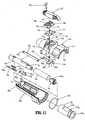
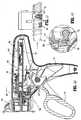
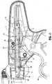
- FIGS. 1-4illustrate one embodiment of the presently disclosed surgical stapling device shown generally as 10.
- surgical stapling device 10includes a handle assembly 12 and an elongated body 14. As illustrated in FIGS. 1 and 2, the length of elongated body 14 may vary to suit a particular surgical procedure.
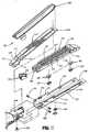
- a disposable loading unit or DLU 16is releasably secured to a distal end of elongated body 14.
- DLU 16includes a proximal body portion 18, which forms an extension of elongated body 14, and a distal tool assembly 20 including a cartridge assembly 22 and an anvil assembly 24.
- Tool assembly 20is pivotably connected to body 18 about an axis substantially perpendicular to the longitudinal axis of elongated body 14.
- Cartridge assembly 22houses a plurality of staples.
- Anvil assembly 24is movable in relation to cartridge assembly 22 between an open position spaced from cartridge assembly 22 and an approximated or clamped position in juxtaposed alignment with cartridge assembly 24.
- the staplesare housed in cartridge assembly 22 to apply linear rows of staples having a length measuring from about 30mm to about 60mm, although other staple configurations and lengths are envisioned. Alternately, other staple line configuration can be provided.
- Handle assembly 12includes a stationary handle member 26, a movable handle or trigger 28 and a barrel portion 30.
- a rotatable member 32is rotatably mounted to the forward end of barrel portion 30 and secured to elongated body 14 to facilitate rotation of elongated body 14 in relation to handle assembly 12.
- An articulation lever 122is supported on a distal portion of barrel portion 30 and is operable, in a manner to be described hereafter, to effect articulation of tool assembly 20 with respect to body portion 18 of DLU 16.
- a pair of return knobs 36are movably supported along barrel portion 30 to effect movement of surgical stapling device 10 from an advanced position to a retracted position, as will be described in detail below.
- handle assembly 12includes a housing 38, which can be formed from plastic molded housing half-sections 38a and 38b. Alternately, other materials may be used to form the housing including metals, e.g., stainless steel.
- Housing 38forms stationary handle 26 and barrel portion 30 of handle assembly 12 (see FIG. 1).
- Movable handle 28is rotatably supported between housing half-sections 38a and 38b about a cylindrical member 40 which is received within an opening 41 in movable handle 28.
- a biasing member 42which is preferably a torsion spring, urges movable handle 28 away from stationary handle 26 to a non-compressed position.
- Movable handle 28includes a pair of throughbores 46 dimensioned to receive a pivot member 47.
- a pawl 48is rotatably supported on pivot member 47 and is biased by a spring 50 towards actuation shaft 52.
- Actuation shaft 52is slidably supported between retracted and advanced positions within barrel portion 30 of housing 38 and includes a distal end defining a recess 54 configured to rotatably receive the proximal end 56 of firing rod 58.
- a spring biased retract arm 57is rotatably mounted between housing half-sections 38a and 38b and includes an extension 57a. Extension 57a is positioned within a slot 59 (FIG. 5) formed in actuation shaft 52 to urge actuation shaft 52 to a fully retracted position.
- Actuation shaft 52includes a toothed rack 60.
- Pawl 48has an engagement finger 62 which is biased by spring 50 towards toothed rack 60 of actuation shaft 52.
- Firing rod 58preferably includes a distal end which is formed from stainless steel and the remaining portion (approximately 90%) formed from aluminum. The two parts may be press fit together. Alternately, firing rod 58 may be formed from a single material or any material or materials having the requisite strength requirements.
- rack lock 64 including pivot members 66is pivotably supported about pivot members 66 between housing half-sections 38a and 38b.
- a biasing member 67awhich is preferably a torsion spring, is positioned to urge rack lock 64 in a clockwise direction as viewed in FIG. 5.
- Rack lock 64includes blocking portion 64a which is positioned within housing 38 to prevent engagement between engagement finger 62 of pawl 48 and toothed rack 60 of actuation shaft 52 when a DLU 16 is not attached to stapling device 10 and movable handle 28 is compressed (See FIG. 18).
- rack lock 64When a DLU is attached to device 10, rack lock 64 is pivoted, in a manner to be described below, to move blocking portion 64a of rack lock 64 to a non-blocking position in which finger 62 of pawl 48 is free to engage toothed rack 60 of actuation shaft 52.
- Rack lock 64also includes a locking portion 64b which is positioned within a recess 52a of actuation shaft 52 to prevent axial movement of actuation shaft 52 until after a DLU 16 (FIG. 1) has been attached to the device.
- a vertical pawl 69is slidably positioned in a slot 68 defined between housing half-sections 38a and 38b.
- Vertical pawl 69is movable from an extended or upward position in which the tip 69a of pawl 69 engages a notch 67 formed in the distal end of actuation shaft 52, to a retracted or downward position in which tip 69a of pawl 69 is spaced from actuation shaft 52.
- a spring 70 supported between housing half-sections 38a and 38bis positioned to urge pawl 69 to the extended position. In the extended position, pawl 69 prevents advancement of actuation shaft 52 to prevent firing of stapling device 10.
- a plunger 72is reciprocably supported between spaced cylindrical channels 74 formed in housing half-sections 38a and 38b.
- Plunger 72includes a cam member 76.
- a spring 78is positioned on each end of plunger 72 within cylindrical channels 74. Springs 78 urge plunger 72 to a position wherein cam member 76 is centrally positioned between a pair of cam surfaces 80 formed on vertical pawl 69.
- Each cam surface 80has a recess 82a (FIG. 19) formed therein for releasably receiving cam member 76 of plunger 72.
- Each end 72a (FIG. 1) of plunger 72extends through stationary handle 26 and can be pressed against the bias of one of springs 78 to force cam member 76 into engagement with a respective one of cam surfaces 80 on vertical pawl 66.
- cam member 76is moved into engagement with one of cam surfaces 80, vertical pawl 69 is urged from the extended position to the retracted position to move tip 69a of vertical pawl 69 out of notch 67 of actuator shaft 52. See FIGS. 61 and 62.
- Stapling device 10is now in a fire-ready position.
- the positioning of tip 76a of cam member 76 in recess 80a of a respective cam surface 80retains vertical pawl in the retracted position to maintain device 10 in the fire-ready position
- a retraction mechanism which includes return knobs 36(FIG. 1) is connected to the proximal end of actuation shaft 52 by a coupling rod 82.
- Coupling rod 82has right and left engagement portions 82a and 82b which extend through elongated slots 83 (FIG. 1) formed in housing half-sections 38a and 38b and are configured to receive return knobs 36.
- a central portion 82c of coupling rod 82is dimensioned to be slidably received within slots 84 formed in the proximal end of actuation shaft 52.
- a release plate 86is supported on one side of actuation shaft 52 by a pair of pins 88. Pins 88 are positioned within angled cam slots 90 formed through release plate 86.
- Coupling rod 82extends through an opening 92 formed in the proximal end of release plate 86.
- coupling rod 82In use, when knobs 36 are pulled rearwardly by a surgeon, coupling rod 82 initially moves release plate 86 rearwardly in relation to actuation shaft 52 as rod 82 slides in slots 84 of actuation shaft 52. As this occurs, pins 88 cam release plate 86 downwardly to a position covering toothed rack 60 of actuation shaft 52 to disengage finger 62 of pawl 48 from toothed rack 60. When coupling rod 82 is pulled rearwardly to a position at which it engages the back end 84a of slots 84, additional rearward movement knobs 36 effect proximal movement of actuation shaft 52 and firing rod 58.
- a hook 96is supported in a slot 98 formed in a top surface of actuation shaft 52.
- Hook 96includes a throughbore 96a dimensioned to receive coupling rod 82.
- a forward end of hook 96includes an upturned portion 98 configured to receive one looped end 100a of spring 100.
- the opposite end of spring 100includes a loop 100b dimensioned to receive a post 102 formed on actuation shaft 52.
- Spring 100is maintained in tension to urge coupling rod 82 towards the forward end of slots 84 in actuation shaft 52.
- rotatable knob 32is preferably formed from molded plastic half-sections 32a and 32b, although other materials, e.g., metals, and manufacturing methods are envisioned.
- the inner surface of the proximal end of rotatable knob 32includes an annular ring 106 dimensioned to be received within an annular slot 108 formed in the forward end of barrel portion 30 of handle assembly 12 to rotatably attach knob 32 to handle assembly 12.
- An O-ring 107is positioned between annular ring 106 and handle assembly 12 to create a friction drag between knob 32 and handle assembly 12. The friction drag prevents free rotation of knob 32 in relation to handle assembly 12.
- the outer surface of the proximal end of rotatable knob 32includes a scalloped configuration 110 to facilitate gripping of rotatable knob 32.
- the inner surface of the distal end of rotatable knob 32defines an opening 112 and includes a protrusion 114 configured and dimensioned to be received within openings 116 formed in the proximal end of elongated body 14.
- the central portion of rotatable knob 32includes a post 118 and defines a transverse channel 120 configured to operably receive the articulation mechanism of the stapling device 10 as will be described in detail below.
- the articulation mechanism of the presently disclosed stapling device 10includes an articulation lever 122, a cam member 124, a cam cover 126, a drive member 128 and an articulation member or link 130 (FIG. 11).
- Articulation lever 122is rotatably secured to post 118 of rotatable knob 32 by a lever pin 132.
- lever pin 132is shown as a separate element from lever 122, it is envisioned that pin 132 may be integrally formed with lever 122.
- a projection 134(FIG. 12) extends downwardly from a bottom surface of lever 122 and is received within an elongated slot 136 formed in cam cover 126.
- Cam member 124is fixedly secured to the base of cam cover 126 by a pair of press-fit projections 126a (FIG. 15) which are received within openings 124a formed in cam member 124.
- a pair of press-fit projections 126a(FIG. 15) which are received within openings 124a formed in cam member 124.
- other known fastening techniquesincluding screws, snap-fit connectors, welding, interlocking members, etc., may be used to secure cam cover 126 to cam member 124.
- Cam cover 126 and cam member 124define an assembly having front and rear ledges 140. The assembly is dimensioned to be slidably positioned in transverse channel 120. Ledges 140 are received within recesses 142 formed in channel 120 to prevent separation of the cam cover and cam member assembly from channel 120 and to limit the cam cover and cam member to linear movement.
- Cam cover 126can be formed of plastic and cam member 124 can be formed of a metal, e.g., stainless steel. Alternately, other
- Transverse channel 120 of rotatable knob 32includes a longitudinal slot 144 extending therethrough.
- Cam member 124has a stepped cam slot 146 formed therethrough.
- a cam pin 148includes a first projection 150 which extends upwardly as viewed in FIG. 12 through longitudinal slot 144 and is received within stepped cam slot 146 of cam member 124.
- Cam pin 148also includes a second projection 152 which extends downwardly as viewed in FIG. 12 into an opening 154 formed in drive member 128.
- Drive member 128includes a body portion 128a including opening 154 and a longitudinal extension 128b.
- An engagement member 156is formed at the distal end of longitudinal extension 128b.
- Engagement member 156is configured to be received within an opening 158 formed in the proximal end of articulation link 130.
- the distal end of articulation link 130also includes engagement structure 160 for engaging an articulation link positioned within a DLU 16 (FIG. 1) as will be described in detail below.
- surgical stapling device 10includes a sensor mechanism for determining if a DLU 16 has been attached to elongated body 14.
- the sensor mechanismincludes a sensor plate 170 (FIG. 5), a rack lock release member 172 and a sensor cap 174 (FIG. 11).
- a sensor tube(not shown) may be positioned between sensor plate 170 and sensor cap 174 to translate movement of sensor plate 170 to sensor cap 174.
- Sensor plate 170is slidably positioned along a flat 58a formed on firing rod 58 and includes a distal end 170a and a proximal end 170b.
- a shim or spacer 170cmay be positioned on sensor plate 170 between an inner wall of elongated body 14. Shim 170c functions to maintain sensor plate 170 in slidable contact with firing rod 58 and in alignment with sensor cap 174, thus preventing sensor plate 170 from overriding and losing axial contact with sensor cap 174.
- Shim 170cmay be integrally or monolithically formed with sensor plate 170.
- Sensor cap 174is slidably positioned within rotatable knob 32 between advanced and retracted positions and includes an articulation locking tab 174a, a proximal flange 174b, and an upper flat surface 174c.
- Upper flat surface 174cis positioned within rotatable knob 32 beneath transverse channel 120 such that tab 174a extends upwardly through an opening in knob 32 into a cutout 176 formed in cam cover 126 and cam member 124.
- tab 174ais positioned within cutout 176 to prevent movement of cam member 124 along transverse channel 120 to prevent articulation of surgical stapling device 10.
- sensor cap 174is moved to the retracted position, in a manner to be described below, tab 174a is moved proximally from cutout 176 to permit movement of cam member 124 along transverse channel 120 and thus, permit articulation of surgical stapling device 10.
- Rack lock release member 172includes a distal end 172a configured to engage flange 174b of sensor cap 174 and a proximal end 172b positioned adjacent rack lock 64.
- a biasing member 180e.g., a coil spring, is positioned within a slot 172c formed in rack lock release member 172 between one end of slot 172c and a finger (not shown) extending into slot 172c from housing assembly 12 to urge lock rack release member 172 distally and thus urge sensor cap 174 and sensor plate 170 distally to the advanced position.
- biasing member 180maintains lock rack release member 172, sensor cap 174 and sensor plate 170 in their advanced positions.
- sensor cap locking tab 174ais positioned within cam member cutout 176 to prevent articulation of surgical stapling device 10.
- lock rack release member 172is also spaced from rack lock 64 such that locking portion 64b of rack lock 64 is positioned within a recess 52a formed in actuation shaft 52 to lock actuation shaft 52 in a fixed retracted position and blocking portion 64a of rack lock 64 is positioned to prevent engagement of pawl 48 and toothed rack 60 of actuation shaft 52.
- proximal end of the DLUengages distal end 170a of sensor plate 170 to move sensor plate 170 proximally.
- Proximal movement of sensor plate 170effects corresponding proximal movement of sensor cap 174 and lock rack release member 172.
- Proximal movement of sensor cap 174 to the retracted positionremoves locking tab 174a from cam member cutout 176 to permit selective articulation of stapling device 10.
- elongated body 14includes a body portion 14a, a body cover 14b and an end cap 14c.
- Body cover 14bis positioned about body portion 14a and end cap 14c is secured to the proximal end of body portion 14a.
- Elongated body 14, as discussed above,is secured between rotatable knob half-sections 32a and 32b via protrusions 114 formed on half-sections 32a and 32b positioned within openings 116 formed in the proximal end of body portion 14a (openings 116a are also formed through end cap 14c).
- Elongated body 14defines a longitudinal throughbore through which firing rod 58, sensor plate 170, and articulation link 130 extend. As discussed above, when elongated body 14 is of an extended length, a sensor tube may also be provided within elongated body 14.
- a lock button 190 and a plate and spring assembly 192are supported in recesses formed in elongated body 14.
- Lock button 190is slidably positioned distally of spring assembly 192 (See FIG. 12) adjacent the distal end of elongated body 14 and includes a distal engagement finger 190a and a proximal tapered abutment surface 190b.
- Finger 190ais positioned to engage the proximal end of a DLU 16 (FIG. 1) during attachment of the DLU 16 to elongated body 14.
- a biasing member 194is provided to urge lock button 190 in a distal direction.
- Plate and spring assembly 192includes a plate 192a having a blocking portion 192b and a spring member 192c.
- Spring member 192ccan be a leaf spring which is secured directly to plate 192a. Alternately, other configurations are envisioned, e.g., the plate and the spring member are separate elements. Blocking portion 192b is positioned adjacent to a notch 196 formed in firing rod 58 (FIG. 12).
- a DLUWhen a DLU is attached to the distal end of elongated body 14, as will be described in further detail below, the DLU is inserted into elongated body 14 and rotated in relation to elongated body 14 to lock DLU 16 thereon.
- the proximal end of DLU 16engages finger 190a of lock button 190 and forces lock button 190 proximally against the bias of spring 194 such that abutment surface 190b of lock button 190 engages plate 192a of assembly 192.
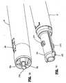
- FIG. 20illustrates surgical stapling device 10 and a DLU 16 prior to attachment of the DLU to elongated body 14 of device 10.
- movable handle 16is rendered inoperable by rack lock 64 which prevents pawl 48 from engaging toothed rack 60 of actuation shaft 52 and locks actuation shaft 52 in a fixed axial position.
- disposable loading unit 16includes proximal body portion 18 which is configured to releasably engage the distal end of elongated body 14, and distal tool assembly 20 which is pivotally secured to the distal end of body portion 18 by a mounting assembly 202 (FIG. 28).
- tool assembly 20includes anvil assembly 24 and cartridge assembly 22 (FIG. 22).
- Anvil assembly 24has anvil portion 204 having a plurality of staple deforming concavities 206 (FIG. 23) and a cover plate 208 secured to a top surface of anvil portion 204 to define a cavity 210 (FIG. 25) therebetween.
- Cover plate 208is provided to prevent pinching of tissue during approximation and firing of stapling device 10.
- Cavity 210is dimensioned to slidably receive a distal end of an axial drive assembly 212 (See FIG. 28).
- a longitudinal slot 214extends through anvil portion 204 to facilitate passage of retention flange 284 (FIG.
- a camming surface 209 formed on anvil portion 204is positioned to be engaged by axial drive assembly 212 to facilitate approximation of the anvil and cartridge assemblies and clamping of tissue 198 (FIG. 25).
- a pair of pivot members 211 formed on anvil portion 204are positioned within slots 213 formed in carrier 216 to guide the anvil portion between the spaced and approximated positions.
- a pair of stabilizing members 215engage a respective shoulder 217 formed on carrier 216 to prevent anvil portion 204 from sliding axially relative to staple cartridge 220 as camming surface 209 is pivoted about pivot members 211.
- Cartridge assembly 22includes carrier 216 which defines an elongated support channel 218.
- Elongated support channel 218is dimensioned and configured to receive a staple cartridge 220.
- a pair of support struts 223 formed on staple cartridge 220are positioned to rest on side walls of carrier 216 to further stabilize staple cartridge 220 within support channel 218.
- Staple cartridge 220includes retention slots 225 for receiving a plurality of fasteners 226 and pushers 228.
- a plurality of spaced apart longitudinal slots 230extend through staple cartridge 220 to accommodate upstanding cam wedges 232 of actuation sled 234.
- a central longitudinal slot 282extends along the length of staple cartridge 220 to facilitate passage of a knife blade 280 (FIG. 28).
- actuation sled 234translates through longitudinal slots 230 of staple cartridge 220 to advance cam wedges 232 into sequential contact with pushers 228, to cause pushers 228 to translate vertically within slots 224 and urge fasteners 226 from slots 224 into the staple deforming cavities 206 of anvil assembly 20.
- mounting assembly 202includes upper and lower mounting portions 236 and 238.
- Each mounting portionincludes a threaded bore 240 on each side thereof dimensioned to receive threaded bolts 242 (See FIG. 22) for securing the proximal end of carrier 216 thereto.
- a pair of centrally located pivot members 244extends between upper and lower mounting portions 236 and 238 through a pair of coupling members 246 which engage the distal end of body portion 18.
- Coupling members 246each include an interlocking proximal portion 248 configured to be received in grooves 249 formed in the proximal end of body portion 18 to retain mounting assembly 202 and body portion 18 in a longitudinally fixed position in relation thereto.
- Body portion 18 of disposable loading unit 16includes an upper housing half 250 and a lower housing half 252 contained within an outer casing 251.
- the proximal end of housing half 250includes engagement lugs 254 for releasably engaging elongated body 14 in a bayonet coupling type fashion.
- the proximal end of housing half 250also includes an insertion tip 193 which will be discussed in further detail below.
- Housing halves 250 and 252define a channel 253 for slidably receiving axial drive assembly 212.
- a second articulation link 256is dimensioned to be slidably positioned within a slot 258 formed between housing halves 250 and 252.
- a pair of blow out plates 255are positioned adjacent the distal end of body portion 18 adjacent the distal end of axial drive assembly 212 to prevent outward bulging of drive assembly 212 during articulation and firing of tool assembly 20.
- FIGS. 28a-hillustrate an alternate embodiment of blow out plates 255 shown generally as blow out plate assembly 254a.
- Blow out plate assembly 254aincludes a flexible body 255a and an H-block 256a.
- Flexible body 255ahas a proximal end 258a and a distal end 260a.
- the distal and proximal endseach include a retaining portion 258b and 260b, respectively.
- Retaining portion 258bis configured to be and is fixedly received and engaged within recesses 250a and/or 252a formed in respective upper and/or lower housing halves 250 and 252 of DLU 16 (FIG. 28b).
- Retaining section 260bincludes a pair of J-shaped attachment members configured to be and which are fixedly received and engaged within recesses 236a and 238a formed in respective upper and/or lower mounting portions 236 and 238 of mounting assembly 202.
- the tips 260c of J-shaped attachment membersare angled to engage and lock into recesses 236a and 238b (FIG. 28g), and are preferably press-fit into the walls that form recesses.
- a locking member 268a(FIGS. 28d-f) includes an H-shaped body having a pair of legs 266a and a central web 267a. Each leg 266a includes an elongated retaining protrusion 270a having tapered ends.
- Locking member 268ais dimensioned to be and is press fit within recesses 250a and 252a formed in respective upper and lower housing halves 250 and 252 of DLU 16 adjacent retaining section 258b to fixedly secure the retaining section 258b within the recesses.
- a central portion of blow out plate assembly 254aincludes a pair of substantially U-shaped spring portions 262a.
- U-shaped spring portion 262aallows the central portion of body 255a to flex slightly outwardly to accommodate sliding and articulating movement of drive assembly 212 (FIG. 28) when tool assembly 20 is actuated, i.e., approximated or fired. As shown in FIG.
- H-block 256Ais positioned with a small gap about spring portions 262a to limit the extent to which U-shaped spring portions 262a are able to flex to prevent buckling of the blow out plate assembly 254a and drive assembly 212 during actuation of device 10.
- a blow-out plate assembly 254ais positioned on each side of drive assembly 212 to prevent outward buckling of drive assembly 212 during actuation of device 10, including when device 10 is articulated.
- second articulation link 256includes at least one elongated metallic plate. In one embodiment, two or more metallic plates are stacked to form link 256.
- the proximal end of articulation link 256includes a hook portion 258 configured to engage articulation link 130 (See FIG. 6) and the distal end includes a loop 260 dimensioned to engage a projection 262 formed on mounting portion 238 of mounting assembly 202.
- Projection 262is laterally offset from pivot pin 244 such that linear movement of second articulation link 256 causes mounting assembly 202 to pivot about pivot pins 244 to articulate tool assembly 20 in relation to body portion 18.
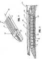
- axial drive assembly 212includes an elongated drive beam 266 including a distal working head 268 and a proximal engagement section 270.
- Drive beam 266may be constructed from a single sheet of material or, preferably, multiple stacked sheets.
- Engagement section 270includes a pair of engagement fingers 270a and 270b which are dimensioned and configured to mountingly engage a pair of corresponding retention slots 272a and 272b formed in drive member 272.
- Drive member 272includes a proximal porthole 274 configured to receive the distal end 276 of firing rod 58 (See FIG. 12) when the proximal end of disposable loading unit 16 is engaged with elongated body 14 of surgical stapling apparatus 10.
- the distal end of working head 268 of drive beam 266is defined by a vertical support strut 278 (FIG. 32) which supports a knife blade 280, and an abutment surface 283 which engages the central portion of actuation sled 234 during a stapling procedure.
- Surface 285is located at the base of surface 283 and is configured to receive a support member 287 (FIG. 39) which is slidably positioned along the bottom of the staple cartridge 220.
- Knife blade 280is positioned to translate slightly behind actuation sled 234 through a central longitudinal slot 282 in staple cartridge 220 (FIG. 22) to form an incision between rows of stapled body tissue.
- a retention flange 284projects distally from vertical strut 278 and supports a cylindrical cam roller 286 at its distal end.
- Cam roller 286is dimensioned and configured to engage cam surface 209 on anvil body 204 to clamp anvil portion 204 against body tissue.
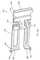
- a locking device 288is pivotally secured to drive member 270 about a pivot pin 290.
- Locking device 288includes a pair of elongate glides 292 and 294 which define a channel 296.
- a web 298joins a portion of the upper surfaces of glides 292 and 294, and is configured and dimensioned to fit within elongated slot 298 formed in drive beam 266 at a position distal of drive member 272.
- Horizontal cams 300 and 302extend from glides 292 and 294 respectively, and are accommodated along an inner surface of lower housing half 252.
- a torsion spring 304is positioned adjacent drive member 270 and engages horizontal cams 300 and 302 (FIG. 36) of locking device 288 to normally bias locking device 288 downward toward lower housing half 252 onto ledge 310.
- Locking device 288translates through housing portion 200 with axial drive assembly 212. Operation of locking device 288 will be described below.
- FIGS. 80-96illustrate an alternate embodiment of the presently disclosed disposable loading unit.
- DLU 516includes a mounting assembly 522.
- Mounting assembly 522includes upper and lower mounting portions 580 and 582.
- a centrally located pivot member 584extends from each of upper and lower mounting portions 580 and 582 through an opening 586a formed in a coupling member 586 which engages the distal end of proximal body portion 518.
- Coupling members 586each include an interlocking proximal portion 588 configured to be received in grooves 590 formed in the proximal end of body portion 518 to retain mounting assembly 522 and body portion 518 in a longitudinally fixed position in relation to each other.
- Body portion 518 of disposable loading unit 516includes an upper housing half 592 and a lower housing half 594 contained within an outer casing 596.
- the proximal end of housing half 592includes engagement lugs 596 for releasably engaging the distal end of instrument 10 (FIG. 20) and an insertion tip 598.
- Lugs 596form a bayonet type coupling with the distal end of instrument 10.
- Housing halves 592 and 594define a channel 600 for slidably receiving axial drive assembly 536.
- An articulation link 602is dimensioned to be slidably positioned within a slot 604 formed housing upper and lower housing halves 592 and 594.
- a pair of blow out plate assemblies 606are positioned adjacent the distal end of body portion 518 adjacent the distal end of axial drive assembly 536 to prevent outward buckling and bulging of drive assembly 536 during articulation and firing of tool assembly 520.
- FIGS. 81-89illustrate details of blowout plate assemblies 606.
- Each blow out plate assembly 606includes a laterally flexible body 610 and an H-block 612.
- Flexible body 610has a proximal end 614 and a distal end 616.
- the distal and proximal endseach include a retaining portion 618 and 620, respectively.
- Retaining portion 618is configured to be and is fixedly received and engaged within recesses 621 and/or 622 formed in upper and/or lower housing halves 592 and 594 of DLU 16 (FIGS. 21, 82, 85).
- Retaining section 620includes a pair of J-shaped attachment members configured to be and which are fixedly received and engaged within recesses 623 and 624 formed in upper and/or lower mounting portions 580 and 582 of mounting assembly 522.
- the tips 630 of J-shaped attachment membersare angled to engage and lock into recesses 623 and 624 (FIG. 82), and are preferably press-fit into the walls that form the recesses.
- a locking member 634(FIGS. 84a-84c) includes an H-shaped body having a pair of legs 636 and a central web 638. Each leg 636 includes an elongated retaining protrusion 640 having tapered ends. Locking member 634 is dimensioned to be and is press fit within recesses 621 and 622 formed in upper and lower housing halves 592 and 594 (FIG. 83) of DLU 16 (FIG. 21) adjacent retaining section 618 to fixedly secure retaining section 618 within the recesses.
- a central portion of blow out plate assembly 606includes spring portion or section which preferably includes a pair of substantially U-shaped spring portions 644.
- U-shaped spring portion 644allows the central portion of body 610 to lengthen axially and flex slightly outwardly relative to or of the longitudinal axis to accommodate sliding and articulating movement of drive assembly 536 (FIG. 80) including when tool assembly 20 (FIG. 21) is actuated, i.e., approximated or fired.
- a limit memberwhich is preferably formed as an H-block 612, is positioned with a small gap about spring portions 644 to limit the extent to which U-shaped spring portions 644 are able to flex to prevent binding or buckling of the blow out plate assembly 606 and drive assembly 536 during actuation of device 510.
- a blow-out plate assembly 606is positioned on each side of drive assembly 536 adjacent the pivot axis of tool assembly 512 to prevent outward buckling and/or binding of drive assembly 536 during actuation of device 510, including when device 510 is articulated.
- an articulation link 602includes at least one elongated metallic plate. Two or more metallic plates can be stacked to form link 602.
- the proximal end of articulation link 602includes a hook portion 660 configured to engage the articulation mechanism positioned within instrument 510 and the distal end includes a loop 662 dimensioned to engage a projection 664 formed on mounting portion 580 of mounting assembly 522. Projection 664 is laterally offset from pivot member 584 such that linear movement of articulation link 602 causes mounting assembly 522 to pivot about pivot members 584 to articulate tool assembly 20 (FIG. 21) in relation to proximal body portion 518.
- Elongated body portion 14 (FIG. 1) or proximal body portion 518may include a retaining member for preventing articulation of tool assembly 520 until a predetermined force has been applied to articulation link 602.
- lower housing half 594 of proximal body portion 518includes a recess 666 dimensioned to receive a biasing member 668, e.g., a compression spring, and a ball 670.
- Articulation member or link 602includes a concavity 672 dimensioned to partially receive ball 670. Engagement between ball 670 and concavity 672 retains articulation link 602 in the unarticulated position until it is desired to articulate the tool assembly. Referring to FIGS.
- a spherical protrusion 674is formed monolithically or integrally with lower housing half 594 and is dimensioned to be received within a recess, here shown as concavity 672, in articulation link 602.
- a cutout 676is formed in lower housing half 594 such that protrusion 674 is supported on a flexible wall 678.
- flexible wall 678flexes downwardly as illustrated in FIG. 21 to permit articulation link 602 to move distally.
- multiple protrusionsmay be provided on the housing to permit the tool assembly to be selectively retained at multiple articulated and non-articulated positions.
- recessesmay be formed in the housing and a protrusion may be provided on the articulation link.
- the above-disclosed retaining member(s)can be formed in elongated body portion 14 of the device.
- axial drive assembly 536includes an elongated drive beam 680 including a distal working head 682 (FIG. 80) and a proximal engagement section 684.
- Drive beam 680may be constructed from a single sheet of material or, preferably, multiple stacked sheets.
- Engagement section 684includes a pair of engagement fingers 686 which are dimensioned and configured to mountingly engage a pair of corresponding retention slots 688 formed in drive member 690.
- Drive member 690includes a proximal porthole 692 configured to receive the distal end of a firing rod of an instrument 10 (FIG. 21) when the proximal end of disposable loading unit 512 is engaged with the elongated body of surgical stapling instrument 10.
- the distal end of drive beam 680is defined by a vertical support strut 694 which supports knife blade 578, and an abutment surface 696 which engages the central portion of actuation sled 234 (FIG. 22) during a stapling procedure.
- Surface 698is located at the base of surface 696 and is configured to receive a support member (not shown) which is slidably positioned along the bottom of the staple cartridge assembly 22 (FIG. 22).
- Knife blade 578is positioned to translate at a position slightly behind actuation sled 234 through a central longitudinal slot in staple cartridge assembly 22 to form an incision between rows of stapled body tissue.
- Retention flange 540projects distally from vertical strut 694 and supports cylindrical cam rollers 700 at its distal end.
- Cam rollers 700are dimensioned and configured to engage cam surface 209 on anvil body 204 to clamp anvil body 204 against body tissue.
- Locking member 702is supported on the proximal end of drive beam 680.
- Locking member 702has a generally H-shaped configuration including first and second legs 704 and 706, a cross-over portion 708, and a pair of arms 710.
- Each leg 704 and 706includes a lateral protrusion 712.
- Cross-over portion 708is positioned within a slot 714 formed in drive beam 680 of drive assembly 536.
- Protrusions 712are received within recesses 716 formed in lower housing half 594.
- Locking member 702also prevents inadvertent partial actuation of DLU 512, such as during shipping, by locking drive beam 680 at a fixed position within DLU 512 until a predetermined axial force has been applied to the drive beam 680.
- a DLU 16is first secured to the distal end of elongated body 14.
- insertion tip 193 of DLU 16is positioned about the distal end 276 of firing rod 58 and moved axially in the direction indicated by arrow "A" in FIGS. 42 and 43.
- a channel (not shown) formed in the distal end of elongated body 14is provided for slidably receiving hook portion 258 of second articulation link 256.
- Lugs 254will also be positioned within channels 14b (FIG. 40) in the distal end of elongated body 14.
- lugs 254engages engagement finger 190a of lock button 190 to move lock button 190 proximally against the bias of spring 194 in the direction indicated by arrow "B" in FIGS. 43 and 44 within elongated body 14.
- abutment surface 190bengages plate 192a of plate and spring assembly 192 to urge blocking portion 192b of plate 192 in the direction indicated by arrow "C” in FIG. 44 into notch 196 formed in firing rod 58 (FIG. 44).
- Positioning of blocking portion 192b in notch 196 of firing rod 58prevents stapling device 10 from being actuated, i.e., approximated or fired, until DLU 16 has been rotated to a locked position.
- DLU 16 and/or body 14is rotated in relation to the other in the direction indicated by arrow "D” in FIG. 45, to move nub 254 out of alignment with finger 190a of lock button 190.
- lock button 190is moved distally by spring 194 in the direction indicated by arrow "E” in FIG. 48 to allow blocking portion 192b of plate 192a to be moved by spring 192c in the direction indicated by arrow "F” in FIG. 48 out of notch 196 of firing rod 58.
- Finger 190ais moved to a position to the side of nub 254 to lock DLU 16 on elongated body 14.
- lock button 190To remove DLU 16 from elongated body after it has been locked in position, lock button 190 must be manually moved proximally and this can only be done with firing rod 58 in the retracted position. As illustrated in FIG. 46, when DLU 16 is locked onto elongated body 14, engagement structure 160 of articulation link 130 is operably engaged with hook portion 258 of second articulation link 256.
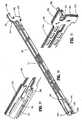
- FIGS. 40A-40Dillustrate an alternate embodiment of the elongated body of device 10 shown generally as 14'.
- Elongated body 14'includes a distal end 15' defining an opening 14a' and generally longitudinally extending channels 14b'. Opening 14a' is dimensioned to receive insertion tip 193 (FIG. 38) of SULU 16 and channels 14b' are dimensioned to receive lugs 254 (FIG. 38) of SULU 16.
- Elongated body 14'differs from body 14 (FIG. 40) in that the walls 14c' defining channels 14b' have chamfered or angled distal ends 14d'. Chamfered distal ends 14d' provide a funnel-like insertion opening 14e' into channels 14b'.
- chamfered distal ends 14d'cam or redirect lugs 254, and thus SULU 16, to its proper or aligned orientation (FIG. 40D).
- chamfered distal ends 14d'are illustrated as having a steep angle of entry, other angles are envisioned, i.e., the chamfered distal ends may have an angle which defines a larger inlet opening 14e' (FIG. 40D) into channel 14b', e.g., 60° or more.
- Other configurations for distal ends 14d'are envisioned.
- the distal ends 14d'may comprise helical surfaces for guiding the SULU in a rotational direction.
- tip 193 of DLU 16engages the distal end 170a of sensor plate 170 to move sensor plate 170 proximally in the direction indicated by arrow “G” in FIG. 44.
- Proximal end 170b of sensor plate 170forces sensor cap 174 to move proximally in the direction indicated by arrows "H” in FIGS. 49 and 50.
- Flange 174b of sensor cap 174is engaged with rack lock release member 172 such that rack lock release member 172 is moved proximally in the direction indicated by arrow "I” in FIG. 51 into engagement with rack lock 64.
- stapling device 10is usable with both articulating and non-articulating DLU's.
- a non-articulating DLU 16a(FIG. 42A) does not include insertion tip 193 (See FIG. 42).
- the sensor mechanism including sensor plate 170, sensor cap 174 and lock release member 172are moved proximally a lesser distance when DLU 16a is attached to elongated body 14. The distance the sensor mechanism is moved proximally is sufficient to disengage rack lock release member 172 from actuation shaft 52 but is insufficient to move tab 174a from cutout 176 (FIG. 52A).
- movable handle 28is moved in the direction indicated by arrow "L" in FIG. 54 through an actuation stroke, i.e., movable handle 28 is compressed towards stationary handle 26 against the bias of torsion spring 42 to move engagement finger 62 of pawl 48 into engagement with a shoulder 52b formed on actuation shaft 52. Subsequent movement of movable handle 28 through the actuation stroke effects advancement of actuation shaft 52 and firing rod 58. As actuation shaft 52 is advanced, notch 67 formed in actuation shaft 52 moves into alignment with vertical pawl 69 and vertical pawl 69 is urged by spring member 70 in the direction indicated by arrow M in FIG. 55 into notch 67 to prevent further advancement of actuation shaft 52 (FIG. 55).
- firing rod 58is connected at its distal end to axial drive assembly 212 including drive beam 266, such that advancement of firing rod 58 effects advancement of drive beam 266 in the direction indicated by arrow "N" in FIGS. 56 and 57.
- cam roller 286moves into engagement with cam surface 209 of anvil portion 204 (FIG. 22) to urge anvil portion 204 in the direction indicated by arrow "O" in FIG. 57 to approximate cartridge and anvil assemblies 22 and 24 and clamp tissue 320 therebetween.
- biasing member 42returns handle 28 in the direction indicated by arrow "P" in FIG. 58 to its non-compressed position spaced from stationary handle 26.
- vertical pawl 69is in the extended position with tip 69a located within notch 67 of actuation shaft 52, thus preventing further advancement of actuation shaft 52.
- cam surfaces 80 on vertical pawl 69are aligned with cam member 76 of plunger 72 (See FIG. 59).
- plunger 72is provided to release or unlock the actuation shaft 52 and put stapling device 10 in a fire-ready position.
- plunger 72is provided to release or unlock the actuation shaft 52 and put stapling device 10 in a fire-ready position.
- cam member 76 of plunger 72engages cam surfaces 80 of vertical pawl 69 to urge vertical pawl 69 in the direction indicated by arrow "R” in FIG. 61 to its retracted position.
- tip 69a of vertical pawl 69is outside of notch 67 of actuation shaft 52 and device 10 is in a fire-ready position.
- Vertical pawl 69is maintained in the retracted position by engagement between cam member 76 of plunger 72 and recesses 82 on cam surfaces 80 of vertical pawl 69.
- movable handle 28is moved in the direction indicated by arrow "L” in FIG. 63 through a second actuation stroke during which, engagement finger 62 of pawl 48 engages toothed rack 60 of actuation shaft 52 to advance actuation shaft 52 and firing rod 58 distally.
- a second abutment surface 52b formed on actuation shaftengages vertical pawl 69 to move vertical pawl 69 downwardly in the direction indicated by arrow "R” in FIG. 64 to disengage cam member 76 of plunger 72 from cam surface 80 of vertical pawl 69 and allow spring 78 to return plunger 72, in the direction indicated by arrow "S” in FIG. 64, to the neutral position.
- drive beam 266is advanced in the direction indicated by arrow "T" in FIGS. 66 and 67 to advance actuation sled 234 through staple cartridge 22 to simultaneously sever tissue with knife 280 (FIG. 31) and drive pushers 228 to sequentially eject staples 226 from the cartridge.
- Surgical stapling device 10is adapted to receive DLU's having staple cartridges with staples in linear rows having a length of from about 30mm to about 60mm.
- Each actuation stroke of movable handle 28 during firing of surgical stapling device 10advances actuation shaft 52 approximately 15mm, although other lengths are envisioned. Accordingly, to fire a cartridge having a 45mm row of staples, movable handle 28 must be moved through three actuation strokes after the approximating or clamping stroke of movable handle 28.
- FIG. 68illustrates operation of the retraction mechanism of surgical stapling device 10.
- coupling rod 82In use, when return knobs 36 are pulled rearwardly by a surgeon in the direction indicated by arrow "U” in FIG. 68, coupling rod 82 initially moves release plate 86 rearwardly in relation to actuation shaft 52 as rod 82 slides in slots 84 of actuation shaft 52 such that pins 88 cam release plate 86 downwardly in the direction indicated by arrow “V” to a position covering toothed rack 60 of actuation shaft 52 and disengaging finger 62 of pawl 48 from toothed rack 60. When coupling rod 82 is pulled rearwardly to a position at which it engages the back end 84a (FIG. 5A) of slots 84, additional rearward movement knobs 36 will effect proximal movement of actuation shaft 52 and firing rod 58.
- articulation lever 122is pivotable to effect articulation of tool assembly 20. More specifically, when articulation lever 122 is rotated or pivoted about lever pin 132 (FIG. 12), projection 134 (FIG. 11) of lever 122 causes cam cover 126 and cam member 124 to move across transverse channel 120 of rotatable knob 32. Movement of cam member 124 across transverse channel 124 causes stepped cam slot 146 to move in relation to first projection 150 of cam pin 148, thus causing cam pin 148 to move through longitudinal slot 144 in rotatable knob 32 (FIG. 11). Longitudinal movement of cam pin 148 effects corresponding longitudinal movement of drive member 128 and articulation link 130. As illustrated in FIG.
- the distal end of articulation link 130is operably connected to the proximal end of second articulation link 256.
- the distal end of articulation link 256is connected to projection 262 on mounting assembly 200 (FIG. 73). Projection 262 is laterally offset from pivot members 244 such that movement of articulation link 256 causes articulation of tool assembly 20. More specifically, when articulation link 130 is retracted (FIG. 69), articulation link 256 is retracted and tool assembly 20 is articulated in a direction indicated by arrow "X" in FIG. 75. When articulation link 130 is advanced (FIG. 70), articulation link 256 is also advanced and tool assembly 20 is articulated in a direction indicated by the arrow "Y" in FIG. 74.
- rotation knob 32is rotatable in relation to handle assembly 12 to rotate elongated body 14 and DLU 16, including tool assembly 20, about a central longitudinal axis of elongated body 14.
- surgical stapling device 10can be rotated while tool assembly 20 is articulated.
- Device 10can also be rotated and then articulated.
- lockout device 288is shown in its prefired position with horizontal cams 300 and 302 resting on top of projections 330 (FIG. 36) formed in the sidewalls of lower housing half 252 (FIG. 37). In this position, locking device 288 is held up out of alignment with projection 332 (FIG. 37) formed in the bottom surface of lower housing half 252, and web 298 is in longitudinal juxtaposition with shelf 334 (FIG. 38) defined in drive beam 266.
- This configurationpermits the anvil 24 (FIG. 39) to be opened and repositioned onto the tissue to be stapled until the surgeon is satisfied with the position without activating locking device 288 to disable the disposable loading unit 16.
- locking device 288rides off of projections 330 (not shown) and is biased into engagement with base lower housing half 252 by spring 304, distal to projection 332. Locking device 288 remains in this configuration throughout firing of the apparatus.
- locking device 288Upon retraction of the drive beam 266 in the direction indicated by arrow "U” in FIG. 78, locking device 288 passes over projections 330 and rides over projection 332 until the distalmost portion of locking device 288 is proximal to projection 332.
- Spring 304biases locking device 288 into juxtaposed alignment with projection 332, effectively disabling the disposable loading unit. If an attempt is made to reactuate the apparatus, the firing rod 58 will abut a proximal end surface of locking device 288 which surface is diagonally sloped to impart a moment about pivot pin 342 such that the distal end of locking device 288 is rotationally urged into contact with projection 332. Continued distal force in the direction indicated by arrow "AA" in FIG. 79, will only serve to increase the moment applied to the locking device thus the locking device will abut projection 332 and inhibit distal movement of the firing rod 58.
Landscapes
- Health & Medical Sciences (AREA)
- Life Sciences & Earth Sciences (AREA)
- Surgery (AREA)
- Heart & Thoracic Surgery (AREA)
- Engineering & Computer Science (AREA)
- Biomedical Technology (AREA)
- Nuclear Medicine, Radiotherapy & Molecular Imaging (AREA)
- Medical Informatics (AREA)
- Molecular Biology (AREA)
- Animal Behavior & Ethology (AREA)
- General Health & Medical Sciences (AREA)
- Public Health (AREA)
- Veterinary Medicine (AREA)
- Surgical Instruments (AREA)
Abstract
Description
- This application claims priority from
U.S. provisional application Serial No. 60/726,546 ("'546 application") filed on October 14, 2005 and titled "Surgical Stapling Device". The entire contents of the '546 application are incorporated herein by reference. - This application relates to a surgical stapling device for applying staples to tissue. More particularly, this application relates to a surgical stapling device having a single use loading unit ("SULU") including a tool member for applying linear rows of staples to tissue and concurrently incising the tissue between the linear rows of staples.
- Surgical devices for grasping or clamping tissue between opposed jaw structure of a tool assembly and thereafter fastening the clamped tissue are well known in the art. These devices may include a knife for incising the fastened tissue. The fasteners are typically in the form of surgical staples but two part fasteners formed of a material suitable for surgical use are also well known.
- Typically, the tool member includes a staple cartridge which houses a plurality of staples arranged in at least two laterally spaced rows and an anvil which includes a plurality of staple forming pockets for receiving and forming staple legs of the staples as the staples are driven from the cartridge. Generally, the stapling operation is effected by a drive member that advances cam wedges longitudinally through the staple cartridge, with the cam wedges acting upon staple pushers to sequentially eject the staples from the staple cartridge. A knife can travel between the staple rows to longitudinally cut and/or open the stapled tissue between the rows of staples.
- In laparoscopic and/or endoscopic surgical procedures, the surgical procedure is performed through a small incision or through a narrow cannula inserted through a small entrance wound in a patient. In conventional or open procedures, surgeons directly access an operative site. Because of reduced patient trauma, shortened patient recovery periods and substantial reduction in overall cost, endoscopic procedures are preferred over open procedures. In order to address the specific needs of endoscopic and/or laparoscopic surgical procedures, endoscopic surgical stapling devices have been developed which provide a surgeon with easier access to the operative site. Typically, these stapling devices include an articulatable tool member which is supported adjacent to the distal end of the stapling device. The tool member can be selectively manipulated to allow a surgeon to manipulate a tool assembly in a confined space.
- Tyco Healthcare Group, LP has manufactured and marketed articulatable endoscopic stapling instruments such as the MULTIFIRE ENDO GIA *30 and MULTIFIRE ENDO GIA *60 for several years. These instruments include a disposable loading unit ("DLU") or single use loading unit ("SULU") which includes a tool assembly, a proximal body portion and a mounting assembly for securing the tool assembly to the proximal body portion. These instruments have provided significant clinical benefits to the field of endoscopic surgery. Nonetheless, improvements in the area of reducing cost and complexity of manufacture are desireable.
- In making improvements or modifications to the current instruments, it would be highly desirable not to sacrifice any of the important benefits of the MULTIFIRE ENDO GIA * 30 and 60 instruments as compared to other commercially available products. For example, any improvement should advantageously provide a fresh knife blade for each firing of the instrument and permit operation of the instrument with multiple size disposable loading units (DLU's).
- A surgical device is provided which includes a body portion having a proximal end and a distal end and defining a longitudinal bore. The distal end of the body portion includes internal walls defining at least one channel. A disposable loading unit is also provided which includes a proximal body portion and a distal tool assembly. The proximal body portion includes an insertion tip dimensioned to be received within the distal end of the body portion. The insertion tip has at least one lug formed thereon. Each of the at least one lug is dimensioned to be slidably received within one of the at least one channel. The distal ends of the internal walls defining the at least one channel are angled to guide the one or more lugs into the at least one channel and properly align the disposable loading unit with the body portion. In one embodiment, the at least one lug includes two lugs and the at least one channel includes two channels. The angled distal ends of the internal walls defining each of the at least one channel define an angle of 60° or more. In one embodiment, the tool assembly includes a cartridge assembly and an anvil assembly. The cartridge assembly includes a plurality of staples. The device can include a handle assembly, wherein the body portion is supported on the handle assembly and extends distally therefrom. The handle assembly can include a stationary handle member, a movable trigger and a barrel portion. In one embodiment, a rotatable member is supported on the barrel portion and the body portion is supported on the rotatable member and is rotatable with the rotatable member in relation to the handle assembly. In one embodiment, the disposable loading unit further includes a mounting portion positioned between the proximal body portion and the tool assembly. The mounting portion pivotally secures the tool assembly to the proximal body portion.
- Various embodiments of the presently disclosed surgical stapling device are described herein with reference to the drawings:
- FIG. 1 is a perspective view of one embodiment of the presently disclosed surgical stapling device;
- FIG. 2 is a perspective view of another embodiment of the presently disclosed surgical stapling device;
- FIG. 3 is a side view of the surgical stapling device shown in FIG. 2;
- FIG. 4 is a top view of the surgical stapling device shown in FIG. 2;
- FIG. 5 is a perspective view with parts separated of the handle assembly of the surgical stapling device shown in FIG. 2;
- FIG. 6 is a front side perspective view of the surgical stapling device shown in FIG. 2 with a housing half section, the rotatable knob, and the outer tube of the elongated body removed;
- FIG. 7 is an enlarged side perspective view with portion broken away of the handle assembly of the surgical stapling device shown in FIG. 2 with the housing half section removed;
- FIG. 8 is an enlarged side view of the handle assembly with portions broken away of the surgical stapling device shown in FIG. 2 with the housing half section removed;
- FIG. 9 is a rear side perspective view of the surgical stapling device shown in FIG. 2 with the housing half section, the rotatable knob, and the outer tube of the elongated body of the instrument removed;
- FIG. 10 is a side vertical cross sectional view of the surgical stapling device shown in FIG. 2;
- FIG. 11 is an exploded side perspective view of the rotatable knob and articulation assembly of the surgical stapling device shown in FIG. 2;
- FIG. 12 is a side cross sectional view of the rotatable knob, articulation assembly and elongated body of the surgical stapling device shown in FIG. 1;
- FIG. 12A is an exploded side perspective view of the elongated body, firing rod, sensor plate and shim of the surgical stapling device shown in FIG. 1;
- FIG. 13 is a side perspective view of the rack lock of the surgical stapling device shown in FIG. 1;
- FIG. 14 is a bottom perspective view of the rack lock shown in FIG. 13;
- FIG. 15 is an exploded top perspective view of the articulation lever, cam cover and cam member assembly, and drive member of the surgical stapling device shown in FIG. 1;
- FIG. 16 is an exploded top perspective view of the elongated body of the surgical stapling device shown in FIG. 2 illustrating the lock button and the plate and spring assembly;
- FIG. 17 is a side perspective view of the elongated body of the surgical stapling device shown in FIG. 2 with the outer tube of the elongated body removed;
- FIG. 18 is an enlarged side view, with portions broken away, of the handle assembly of the surgical stapling device shown in FIG. 2 with a housing half section removed and the pawl engaging the lock rack;
- FIG. 19 is a top perspective view of the pawl and plunger mechanism of the surgical stapling device shown in FIG. 2;
- FIG. 20 is a top front perspective view of the surgical stapling device shown in FIG. 2 with the disposable loading unit detached from the elongated body;
- FIG. 21 is a side cross sectional view of the disposable loading unit of the surgical stapling device shown in FIG. 2;
- FIG. 22 is an exploded top perspective view of the tool assembly of the disposable loading unit shown in FIG. 21;
- FIG. 23 is an enlarged perspective view, with portions broken away, of the distal end of the anvil assembly of the surgical stapling device shown in FIG. 2 showing a plurality of staple forming cavities;
- FIG. 24 is an enlarged top perspective view of the distal end of the staple cartridge of the surgical stapling device shown in FIG. 2;
- FIG. 25 is a side cross sectional view taken along a portion of section lines 25-25 of FIG. 24;
- FIG. 26 is an enlarged perspective view of the actuation sled, the pushers and the fasteners of the surgical stapling device shown in FIG. 2;
- FIG. 27 is a bottom perspective view of the staple cartridge shown in FIG. 22;
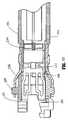
- FIG. 28 is an enlarged exploded top perspective view of the proximal body portion and mounting assembly of the disposable loading unit shown in FIG. 21;
- FIG. 28a is an enlarged side perspective view of the blow out plate assembly of the surgical stapling device shown in FIG. 2;
- FIG. 28b is a top view, with portions broken away, of the proximal end of the tool assembly and the distal end of the proximal body portion of the disposable loading unit with the top housing half of the disposable loading unit removed;
- FIG. 28c is a side vertical cross sectional view of the proximal end of the tool assembly and the distal end of the proximal body portion of the disposable loading unit of the surgical stapling device shown in FIG. 2;
- FIG. 28d is a top perspective view of the locking member of the blow out plate assembly of the surgical stapling device shown in FIG. 2;
- FIG. 28e is a front elevational view of the locking member shown in FIG. 28d;
- FIG. 28f is a top view, with portions broken away, of the locking member shown in FIG. 28d;
- FIG 28g is a vertical cross sectional view, with portions broken away, of the proximal end of the tool assembly and the distal end of the proximal body portion of the disposable loading unit of the surgical stapling device shown in FIG. 2;
- FIG. 28h is a transverse cross sectional view, with portions broken away, of the proximal end of the tool assembly and the distal end of the proximal body portion of the disposable loading unit of the surgical stapling device shown in FIG. 2;
- FIG. 29 is an enlarged perspective view, with portions broken away, of the mounting assembly of the disposable loading unit shown in FIG. 21 mounted to a distal end portion of the proximal body portion;
- FIG. 30 is a perspective view of the distal end of the proximal body portion and the mounting assembly of the disposable loading unit shown in FIG. 21 with the upper housing half section removed;
- FIG. 31 is a perspective view of the proximal body portion and the mounting assembly of the disposable loading unit shown in FIG. 21 with the upper housing half section and outer tube removed;
- FIG. 32 is a perspective view with parts separated of the axial drive assembly of the surgical stapling device shown in FIG. 2;
- FIG. 33 is an enlarged perspective view of the axial drive assembly shown in FIG. 32;
- FIG. 34 is an enlarged perspective view of the distal end of the axial drive assembly shown in FIG. 33;
- FIG. 35 is an enlarged perspective view of the distal end of the axial drive assembly shown in FIG. 32;
- FIG. 36 is an enlarged perspective view of the locking device shown in FIG. 32;
- FIG. 37 is an enlarged perspective view of a lower housing half of the proximal body portion of the disposable loading unit shown in FIG. 21;
- FIG. 38 is a top horizontal cross sectional view of the proximal end of the disposable loading unit shown in FIG. 21;
- FIG. 39 is a side cross sectional view of the distal end of the proximal body portion, the mounting assembly and the proximal end of the tool assembly of the disposable loading unit shown in FIG. 21;
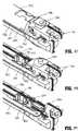
- FIG. 40 is a perspective view of the distal end of the elongated body portion of the surgical stapling device shown in FIG. 2;
- FIG. 40A is a side perspective view of an alternate embodiment of the elongated body of the surgical stapling device shown in FIG. 40;
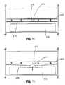
- FIG. 40B is a side view of the SULU shown in FIG. 41 positioned adjacent the distal end of the elongated body shown in FIG. 40A prior to insertion of the SULU into the elongated body;
- FIG. 40C is a side view of the SULU shown in FIG. 41 positioned adjacent the distal end of the elongated body shown in FIG 40A during initial insertion of the SULU into the elongated body;
- FIG. 40D a side view of the SULU shown in FIG. 41 positioned adjacent the distal end of the elongated body shown in FIG 40A during the final insertion of the SULU into the elongated body;
- FIG. 41 is a perspective view of the proximal end of the disposable loading unit shown in FIG. 21;
- FIG. 42 is a side view of the proximal end of the disposable loading unit shown in FIG. 21 and the distal end of the elongated body portion of the surgical stapling device shown in FIG. 2 prior to attachment of the disposable loading unit to the elongated body portion;
- FIG. 42a is an enlarged perspective view of the proximal end of the disposable loading unit shown in FIG. 21;
- FIG. 43 is a side view of the proximal end of the disposable loading unit and the distal end of the elongated body portion during attachment of the disposable loading unit to the elongated body portion of the surgical stapling device shown in FIG. 2;
- FIG. 44 is a side cross sectional view of the distal end of the elongated body portion of the surgical stapling device shown in FIG. 2 and the proximal end of the disposable loading unit shown in FIG. 21 during attachment of the disposable loading unit to the elongated body portion;
- FIG. 45 is a side view of the proximal end of the disposable loading unit and the distal end of the elongated body portion during attachment of the disposable loading unit to the elongated body portion;
- FIG. 46 is a perspective partial cut away view, with portions broken away, of the proximal end of the disposable loading unit and the distal end of the elongated body portion during attachment of the disposable loading unit to the elongated body portion;
- FIG. 47 is a side cross-sectional view of the surgical stapling device shown in FIG. 2 in the unapproximated position;
- FIG. 48 is an enlarged view of the indicated area of detail shown in FIG. 47;
- FIG. 49 is an enlarged view of the indicated area of detail shown in FIG. 47;
- FIG. 50 is a cross-sectional view taken along section lines 50-50 shown in FIG. 49;
- FIG. 51 is a side view of the handle assembly of the surgical stapling device shown in FIG. 2 with the handle housing and the rotatable knob shown in phantom and illustrating the sequence of operation during attachment of a disposable loading unit to the surgical stapling device;
- FIG. 52 is a top view, with portions broken away, of the cam cover and cam member assembly and sensor cap illustrating the sequence of operation during attachment of a disposable loading unit to the elongated body of the surgical stapling device;
- FIG. 52A is a top view of the cam cover and cam member assembly and sensor cap prior to attachment of a disposable loading unit to the elongated body portion of the surgical stapling device;
- FIG. 53 is a side cross-sectional view of the tool assembly of the surgical stapling device shown in FIG. 2 in the unapproximated position;
- FIG. 54 is a side cross-sectional view, with portions broken away, of the handle assembly of the surgical stapling device shown in FIG. 2 during approximation of the surgical stapling device.
- FIG. 55 is an enlarged view of the indicated area of detail shown in FIG. 54;
- FIG. 56 is a side cross-sectional view of the proximal end of the proximal body portion of the disposable loading unit of the surgical stapling device shown in FIG. 2 after the device has been approximated;
- FIG. 57 is a side cross sectional view of the tool assembly of the disposable loading unit of the surgical stapling device shown in FIG. 2 in the approximated position;
- FIG. 58 is a side cross sectional view of the handle assembly of the surgical stapling device shown in FIG. 2 in the approximated position with the handle in the non-compressed position;
- FIG. 59 is a cross-sectional view taken along a portion of section lines 59-59 of FIG. 58;
- FIG. 60 is a side cross sectional view of the handle assembly of the surgical stapling device shown in FIG. 2 with the plunger disengaged from the vertical pawl;
- FIG. 61 is a cross-sectional view taken along a portion of section lines 61-61 of FIG. 60;
- FIG. 62 is an enlarged view of the indicated area of detail shown in FIG. 60;
- FIG. 63 is a side cross-sectional view of the handle assembly of the surgical stapling device shown in FIG. 2 during the firing stroke of the surgical stapling device;
- FIG. 64 is a cross sectional view taken along a portion of section lines 64-64 of FIG. 63;
- FIG. 65 is an enlarged view of the indicated area of detail shown in FIG. 63;
- FIG. 66 is a cross-sectional view of the distal end of the tool assembly during the firing stroke of the surgical stapling device;
- FIG. 67 is a side cross-sectional view of the tool assembly of the surgical stapling device shown in FIG. 2 after completion of the firing stroke;
- FIG. 68 is a side view of the handle assembly of the surgical stapling device shown in FIG. 2 during retraction of the actuation shaft;
- FIG. 69 is a top view of the rotatable knob and articulation mechanism of the surgical stapling device shown in FIG. 2 with the tool assembly articulated in a first direction with the rotatable knob and the articulation lever shown in phantom;
- FIG. 70 is a top view of the rotatable knob and articulation mechanism of the surgical stapling device shown in FIG. 2 with the tool assembly articulated in a second direction;
- FIG. 71 is a side perspective view of the articulation mechanism of the surgical stapling device shown in FIG. 2;
- FIG. 72 is a top view of the rotatable knob and articulation mechanism of the surgical stapling device shown in FIG. 2 with the rotatable knob and articulation lever shown in phantom;
- FIG. 73 is a top view of the distal end of the disposable loading unit prior to articulation of the tool assembly;
- FIG. 74 is a top view of the distal end of the disposable loading unit during articulation of the tool assembly in a first direction;
- FIG. 75 is a top view of the distal end of the disposable loading unit shown in FIG. 21 during articulation of the tool assembly in a second direction;
- FIG. 76 is a side perspective view of the surgical stapling device shown in FIG. 2 with the tool assembly articulated in a first direction;
- FIG. 77 is a side perspective view of the surgical stapling device shown in FIG. 2 with the tool assembly articulated in a second direction;
- FIG. 78 is a side partial cross-sectional view of a portion of the disposable loading unit shown in FIG. 21 during retraction of the locking device;
- FIG. 79 is a side partial cross-sectional view of a portion of the disposable loading unit shown in FIG. 21 with the locking device in the locked position;
- FIG. 80 is an enlarged exploded perspective view of the proximal body portion and mounting assembly of another preferred embodiment of the disposable loading unit;
- FIG. 81 is an enlarged side perspective view of the blow out plate assembly of the disposable loading unit shown in FIG. 80;
- FIG. 82 is a top view, with portions broken away, of the proximal end of the tool assembly and the distal end of the proximal body portion of the disposable loading unit shown in FIG. 80 with the top housing half of the disposable loading unit removed;
- FIG. 83 is a side cross-sectional view of the proximal end of the tool assembly and the distal end of the proximal body portion of the disposable loading unit shown in FIG. 80;
- FIG. 84A is a top perspective view of the locking member of the blow out plate assembly of the disposable loading unit shown in FIG. 80;
- FIG. 84B is a front elevational view of the locking member shown in FIG. 84A;
- FIG. 84C is a top view of the locking member shown in FIG. 84A;
- FIG. 85 is a side cross-sectional view of the proximal end of the tool assembly and the distal end of the proximal body portion of the disposable loading unit shown in FIG. 80;
- FIG. 86 is a transverse cross-sectional view of the proximal end of the tool assembly and the distal end of the proximal body portion of the disposable loading unit shown in FIG. 80;
- FIG. 87 is a perspective view of the distal end of the proximal body portion and the mounting assembly of the disposable loading unit shown in FIG. 80;
- FIG. 88 is a perspective view of the distal end of the proximal body portion and mounting assembly of the disposable loading unit shown in FIG. 80 with the upper housing half removed;
- FIG. 89 is a perspective view of the distal end of the proximal body portion with the upper housing half section removed;
- FIG. 90 is a perspective view of the upper housing half of the proximal body portion of the disposable loading unit shown in FIG. 80;
- FIG. 90A is an enlarged view of the indicated area of detail shown in FIG. 90;
- FIG. 91 is a perspective view of the articulation link of the disposable loading unit shown in FIG. 80;
- FIG. 91A is an enlarged view of the indicated area of detail shown in FIG. 91;
- FIG. 92 is a side view of the upper housing half and the articulation link of the disposable loading unit shown in FIG. 80;
- FIG. 93 is a side view of the upper housing half and articulation link of the disposable loading unit shown in FIG. 80 as the articulation link is advanced to articulate the tool assembly;
- FIG. 94 is a perspective view of the locking member of the disposable loading unit shown in FIG. 80;
- FIG. 95 is a perspective view of the proximal end of the proximal body portion of the disposable loading unit shown in FIG. 80; and
- FIG. 96 is a top view of the proximal end of the proximal body portion of the disposable loading unit shown in FIG. 80.
- Embodiments of the presently disclosed surgical stapling device will now be described in detail with reference to the drawings in which like reference numerals designate identical or corresponding elements in each of the several views.
- In the description that follows, the term "proximal", as is traditional, will refer to the end of the stapling device which is closest to the operator, while the term distal will refer to the end of the device which is furthest from the operator.
- FIGS. 1-4 illustrate one embodiment of the presently disclosed surgical stapling device shown generally as 10. Briefly,
surgical stapling device 10 includes ahandle assembly 12 and anelongated body 14. As illustrated in FIGS. 1 and 2, the length ofelongated body 14 may vary to suit a particular surgical procedure. A disposable loading unit orDLU 16 is releasably secured to a distal end ofelongated body 14.DLU 16 includes aproximal body portion 18, which forms an extension ofelongated body 14, and adistal tool assembly 20 including acartridge assembly 22 and ananvil assembly 24.Tool assembly 20 is pivotably connected tobody 18 about an axis substantially perpendicular to the longitudinal axis ofelongated body 14.Cartridge assembly 22 houses a plurality of staples.Anvil assembly 24 is movable in relation tocartridge assembly 22 between an open position spaced fromcartridge assembly 22 and an approximated or clamped position in juxtaposed alignment withcartridge assembly 24. In one embodiment, the staples are housed incartridge assembly 22 to apply linear rows of staples having a length measuring from about 30mm to about 60mm, although other staple configurations and lengths are envisioned. Alternately, other staple line configuration can be provided. - Handle
assembly 12 includes astationary handle member 26, a movable handle or trigger 28 and abarrel portion 30. Arotatable member 32 is rotatably mounted to the forward end ofbarrel portion 30 and secured toelongated body 14 to facilitate rotation ofelongated body 14 in relation to handleassembly 12. Anarticulation lever 122 is supported on a distal portion ofbarrel portion 30 and is operable, in a manner to be described hereafter, to effect articulation oftool assembly 20 with respect tobody portion 18 ofDLU 16. A pair ofreturn knobs 36 are movably supported alongbarrel portion 30 to effect movement ofsurgical stapling device 10 from an advanced position to a retracted position, as will be described in detail below. - Referring to FIGS. 5-8, handle
assembly 12 includes ahousing 38, which can be formed from plastic molded housing half-sections 38a and 38b. Alternately, other materials may be used to form the housing including metals, e.g., stainless steel.Housing 38 formsstationary handle 26 andbarrel portion 30 of handle assembly 12 (see FIG. 1).Movable handle 28 is rotatably supported between housing half-sections 38a and 38b about acylindrical member 40 which is received within anopening 41 inmovable handle 28. A biasingmember 42, which is preferably a torsion spring, urgesmovable handle 28 away fromstationary handle 26 to a non-compressed position.Movable handle 28 includes a pair ofthroughbores 46 dimensioned to receive apivot member 47. Apawl 48 is rotatably supported onpivot member 47 and is biased by aspring 50 towardsactuation shaft 52. Actuation shaft 52 is slidably supported between retracted and advanced positions withinbarrel portion 30 ofhousing 38 and includes a distal end defining arecess 54 configured to rotatably receive theproximal end 56 of firingrod 58. A spring biased retractarm 57 is rotatably mounted between housing half-sections 38a and 38b and includes an extension 57a. Extension 57a is positioned within a slot 59 (FIG. 5) formed inactuation shaft 52 to urgeactuation shaft 52 to a fully retracted position.Actuation shaft 52 includes atoothed rack 60.Pawl 48 has anengagement finger 62 which is biased byspring 50 towardstoothed rack 60 ofactuation shaft 52. Whenmovable handle 28 is actuated, i.e., is compressed towardsstationary handle 26 against the bias ofspring 42,engagement finger 62 ofpawl 48 engagestoothed rack 60 ofactuation shaft 52 to advanceactuation shaft 52 and firingrod 58 distally. Firingrod 58 preferably includes a distal end which is formed from stainless steel and the remaining portion (approximately 90%) formed from aluminum. The two parts may be press fit together. Alternately, firingrod 58 may be formed from a single material or any material or materials having the requisite strength requirements.- Referring to FIGS. 5, 13 and 14,
rack lock 64 includingpivot members 66 is pivotably supported aboutpivot members 66 between housing half-sections 38a and 38b. A biasing member 67a, which is preferably a torsion spring, is positioned to urgerack lock 64 in a clockwise direction as viewed in FIG. 5.Rack lock 64 includes blockingportion 64a which is positioned withinhousing 38 to prevent engagement betweenengagement finger 62 ofpawl 48 andtoothed rack 60 ofactuation shaft 52 when aDLU 16 is not attached to staplingdevice 10 andmovable handle 28 is compressed (See FIG. 18). When a DLU is attached todevice 10,rack lock 64 is pivoted, in a manner to be described below, to move blockingportion 64a ofrack lock 64 to a non-blocking position in whichfinger 62 ofpawl 48 is free to engagetoothed rack 60 ofactuation shaft 52.Rack lock 64 also includes a locking portion 64b which is positioned within arecess 52a ofactuation shaft 52 to prevent axial movement ofactuation shaft 52 until after a DLU 16 (FIG. 1) has been attached to the device. - Referring to FIGS. 5 and 19, a
vertical pawl 69 is slidably positioned in aslot 68 defined between housing half-sections 38a and 38b.Vertical pawl 69 is movable from an extended or upward position in which thetip 69a ofpawl 69 engages anotch 67 formed in the distal end ofactuation shaft 52, to a retracted or downward position in whichtip 69a ofpawl 69 is spaced fromactuation shaft 52. Aspring 70 supported between housing half-sections 38a and 38b is positioned to urgepawl 69 to the extended position. In the extended position,pawl 69 prevents advancement ofactuation shaft 52 to prevent firing of staplingdevice 10. - A
plunger 72 is reciprocably supported between spacedcylindrical channels 74 formed in housing half-sections 38a and 38b.Plunger 72 includes acam member 76. Aspring 78 is positioned on each end ofplunger 72 withincylindrical channels 74.Springs 78urge plunger 72 to a position whereincam member 76 is centrally positioned between a pair of cam surfaces 80 formed onvertical pawl 69. Eachcam surface 80 has arecess 82a (FIG. 19) formed therein for releasably receivingcam member 76 ofplunger 72. - Each
end 72a (FIG. 1) ofplunger 72 extends throughstationary handle 26 and can be pressed against the bias of one ofsprings 78 to forcecam member 76 into engagement with a respective one of cam surfaces 80 onvertical pawl 66. Whencam member 76 is moved into engagement with one of cam surfaces 80,vertical pawl 69 is urged from the extended position to the retracted position to movetip 69a ofvertical pawl 69 out ofnotch 67 ofactuator shaft 52. See FIGS. 61 and 62.Stapling device 10 is now in a fire-ready position. The positioning of tip 76a ofcam member 76 in recess 80a of arespective cam surface 80 retains vertical pawl in the retracted position to maintaindevice 10 in the fire-ready position - A retraction mechanism which includes return knobs 36 (FIG. 1) is connected to the proximal end of
actuation shaft 52 by acoupling rod 82. Couplingrod 82 has right and leftengagement portions sections 38a and 38b and are configured to receivereturn knobs 36. Acentral portion 82c ofcoupling rod 82 is dimensioned to be slidably received withinslots 84 formed in the proximal end ofactuation shaft 52. Arelease plate 86 is supported on one side ofactuation shaft 52 by a pair ofpins 88.Pins 88 are positioned withinangled cam slots 90 formed throughrelease plate 86. Couplingrod 82 extends through anopening 92 formed in the proximal end ofrelease plate 86. - In use, when knobs 36 are pulled rearwardly by a surgeon,
coupling rod 82 initially movesrelease plate 86 rearwardly in relation toactuation shaft 52 asrod 82 slides inslots 84 ofactuation shaft 52. As this occurs, pins 88cam release plate 86 downwardly to a position coveringtoothed rack 60 ofactuation shaft 52 to disengagefinger 62 ofpawl 48 fromtoothed rack 60. When couplingrod 82 is pulled rearwardly to a position at which it engages the back end 84a ofslots 84, additional rearward movement knobs 36 effect proximal movement ofactuation shaft 52 and firingrod 58. - A
hook 96 is supported in aslot 98 formed in a top surface ofactuation shaft 52.Hook 96 includes athroughbore 96a dimensioned to receivecoupling rod 82. A forward end ofhook 96 includes anupturned portion 98 configured to receive one looped end 100a ofspring 100. The opposite end ofspring 100 includes aloop 100b dimensioned to receive apost 102 formed onactuation shaft 52.Spring 100 is maintained in tension to urgecoupling rod 82 towards the forward end ofslots 84 inactuation shaft 52. When couplingrod 82 is positioned at the forward end ofslots 84 ofactuation shaft 52,release plate 86 is held or cammed in a raised position abovetoothed rack 60 of actuation shaft 52 (FIG. 8). - Referring to FIGS. 5 and 10-12,
rotatable knob 32 is preferably formed from molded plastic half-sections rotatable knob 32 includes anannular ring 106 dimensioned to be received within anannular slot 108 formed in the forward end ofbarrel portion 30 ofhandle assembly 12 to rotatably attachknob 32 to handleassembly 12. An O-ring 107 is positioned betweenannular ring 106 and handleassembly 12 to create a friction drag betweenknob 32 and handleassembly 12. The friction drag prevents free rotation ofknob 32 in relation to handleassembly 12. The outer surface of the proximal end ofrotatable knob 32 includes ascalloped configuration 110 to facilitate gripping ofrotatable knob 32. The inner surface of the distal end ofrotatable knob 32 defines anopening 112 and includes aprotrusion 114 configured and dimensioned to be received withinopenings 116 formed in the proximal end ofelongated body 14. The central portion ofrotatable knob 32 includes apost 118 and defines atransverse channel 120 configured to operably receive the articulation mechanism of the staplingdevice 10 as will be described in detail below. - Referring also to FIG. 15, the articulation mechanism of the presently disclosed stapling
device 10 includes anarticulation lever 122, acam member 124, acam cover 126, adrive member 128 and an articulation member or link 130 (FIG. 11).Articulation lever 122 is rotatably secured to post 118 ofrotatable knob 32 by alever pin 132. Althoughlever pin 132 is shown as a separate element fromlever 122, it is envisioned thatpin 132 may be integrally formed withlever 122. A projection 134 (FIG. 12) extends downwardly from a bottom surface oflever 122 and is received within anelongated slot 136 formed incam cover 126.Cam member 124 is fixedly secured to the base ofcam cover 126 by a pair of press-fit projections 126a (FIG. 15) which are received withinopenings 124a formed incam member 124. Alternately, other known fastening techniques including screws, snap-fit connectors, welding, interlocking members, etc., may be used to securecam cover 126 tocam member 124.Cam cover 126 andcam member 124 define an assembly having front andrear ledges 140. The assembly is dimensioned to be slidably positioned intransverse channel 120.Ledges 140 are received withinrecesses 142 formed inchannel 120 to prevent separation of the cam cover and cam member assembly fromchannel 120 and to limit the cam cover and cam member to linear movement.Cam cover 126 can be formed of plastic andcam member 124 can be formed of a metal, e.g., stainless steel. Alternately, other materials of construction are envisioned. Transverse channel 120 ofrotatable knob 32 includes alongitudinal slot 144 extending therethrough.Cam member 124 has a steppedcam slot 146 formed therethrough. Acam pin 148 includes afirst projection 150 which extends upwardly as viewed in FIG. 12 throughlongitudinal slot 144 and is received within steppedcam slot 146 ofcam member 124.Cam pin 148 also includes asecond projection 152 which extends downwardly as viewed in FIG. 12 into anopening 154 formed indrive member 128.Drive member 128 includes abody portion 128a including opening 154 and a longitudinal extension 128b. Anengagement member 156 is formed at the distal end of longitudinal extension 128b.Engagement member 156 is configured to be received within an opening 158 formed in the proximal end ofarticulation link 130. The distal end ofarticulation link 130 also includesengagement structure 160 for engaging an articulation link positioned within a DLU 16 (FIG. 1) as will be described in detail below.- In operation, when
articulation lever 122 is rotated aboutlever pin 132,projection 134 causes thecam cover 126 andcam member 124 assembly to move acrosstransverse channel 120. Movement ofcam member 124 acrosstransverse channel 124 causes steppedcam slot 146 to move in relation tofirst projection 150 ofcam pin 148, thus causingcam pin 148 to move throughlongitudinal slot 144. Longitudinal movement ofcam pin 148 effects corresponding longitudinal movement ofdrive member 128 andarticulation link 130. The interconnection ofarticulation link 130 and the articulation structure withinDLU 16 will be described in detail below. - Referring to FIGS. 5-12,
surgical stapling device 10 includes a sensor mechanism for determining if aDLU 16 has been attached toelongated body 14. The sensor mechanism includes a sensor plate 170 (FIG. 5), a racklock release member 172 and a sensor cap 174 (FIG. 11). When elongatedbody 14 is of an extended length, a sensor tube (not shown) may be positioned betweensensor plate 170 andsensor cap 174 to translate movement ofsensor plate 170 tosensor cap 174.Sensor plate 170 is slidably positioned along a flat 58a formed on firingrod 58 and includes adistal end 170a and aproximal end 170b. In an alternate embodiment, a shim or spacer 170c (FIG. 12A) may be positioned onsensor plate 170 between an inner wall ofelongated body 14. Shim 170c functions to maintainsensor plate 170 in slidable contact with firingrod 58 and in alignment withsensor cap 174, thus preventingsensor plate 170 from overriding and losing axial contact withsensor cap 174. Although shown as being a separate element fromsensor plate 170, shim 170c may be integrally or monolithically formed withsensor plate 170.Sensor cap 174 is slidably positioned withinrotatable knob 32 between advanced and retracted positions and includes anarticulation locking tab 174a, a proximal flange 174b, and an upper flat surface 174c. (See FIG. 11.) Upper flat surface 174c is positioned withinrotatable knob 32 beneathtransverse channel 120 such thattab 174a extends upwardly through an opening inknob 32 into acutout 176 formed incam cover 126 andcam member 124. Whensensor cap 174 is in the advanced position,tab 174a is positioned withincutout 176 to prevent movement ofcam member 124 alongtransverse channel 120 to prevent articulation ofsurgical stapling device 10. Whensensor cap 174 is moved to the retracted position, in a manner to be described below,tab 174a is moved proximally fromcutout 176 to permit movement ofcam member 124 alongtransverse channel 120 and thus, permit articulation ofsurgical stapling device 10. - Rack
lock release member 172 includes a distal end 172a configured to engage flange 174b ofsensor cap 174 and a proximal end 172b positionedadjacent rack lock 64. A biasingmember 180, e.g., a coil spring, is positioned within a slot 172c formed in racklock release member 172 between one end of slot 172c and a finger (not shown) extending into slot 172c fromhousing assembly 12 to urge lockrack release member 172 distally and thus urgesensor cap 174 andsensor plate 170 distally to the advanced position. - In operation, when a DLU is not attached to
surgical stapling device 10, biasingmember 180 maintains lockrack release member 172,sensor cap 174 andsensor plate 170 in their advanced positions. As discussed above, in the advanced position, sensorcap locking tab 174a is positioned withincam member cutout 176 to prevent articulation ofsurgical stapling device 10. In the advanced position, lockrack release member 172 is also spaced fromrack lock 64 such that locking portion 64b ofrack lock 64 is positioned within arecess 52a formed inactuation shaft 52 to lockactuation shaft 52 in a fixed retracted position and blockingportion 64a ofrack lock 64 is positioned to prevent engagement ofpawl 48 andtoothed rack 60 ofactuation shaft 52. When aDLU 16 is secured to the distal end ofelongated body 14, the proximal end of the DLU engagesdistal end 170a ofsensor plate 170 to movesensor plate 170 proximally. Proximal movement ofsensor plate 170 effects corresponding proximal movement ofsensor cap 174 and lockrack release member 172. Proximal movement ofsensor cap 174 to the retracted position removes lockingtab 174a fromcam member cutout 176 to permit selective articulation of staplingdevice 10. When lockrack release member 172 is moved proximally, the proximal end 172b ofmember 172 abuts against a bottom surface ofrack lock 64 to pivot locking portion 64b ofrack lock 64 upwardly out ofrecess 52a ofactuation shaft 52 to facilitate advancement ofactuation shaft 52 and to pivot blockingportion 64a ofrack lock 64 to a position not obstructing engagement betweenengagement finger 62 ofpawl 48 andtoothed rack 60 ofactuation shaft 52. - Referring to FIGS. 11, 12, 16 and 17,
elongated body 14 includes abody portion 14a, abody cover 14b and anend cap 14c.Body cover 14b is positioned aboutbody portion 14a andend cap 14c is secured to the proximal end ofbody portion 14a.Elongated body 14, as discussed above, is secured between rotatable knob half-sections protrusions 114 formed on half-sections openings 116 formed in the proximal end ofbody portion 14a (openings 116a are also formed throughend cap 14c).Elongated body 14 defines a longitudinal throughbore through which firingrod 58,sensor plate 170, and articulation link 130 extend. As discussed above, whenelongated body 14 is of an extended length, a sensor tube may also be provided withinelongated body 14. - A
lock button 190 and a plate andspring assembly 192 are supported in recesses formed inelongated body 14.Lock button 190 is slidably positioned distally of spring assembly 192 (See FIG. 12) adjacent the distal end ofelongated body 14 and includes adistal engagement finger 190a and a proximaltapered abutment surface 190b.Finger 190a is positioned to engage the proximal end of a DLU 16 (FIG. 1) during attachment of theDLU 16 toelongated body 14. A biasingmember 194 is provided to urgelock button 190 in a distal direction. Plate andspring assembly 192 includes aplate 192a having a blocking portion 192b and aspring member 192c.Spring member 192c can be a leaf spring which is secured directly toplate 192a. Alternately, other configurations are envisioned, e.g., the plate and the spring member are separate elements. Blocking portion 192b is positioned adjacent to anotch 196 formed in firing rod 58 (FIG. 12). - When a DLU is attached to the distal end of
elongated body 14, as will be described in further detail below, the DLU is inserted into elongatedbody 14 and rotated in relation toelongated body 14 to lockDLU 16 thereon. During insertion ofDLU 16 into elongatedbody 14, the proximal end ofDLU 16 engagesfinger 190a oflock button 190 and forces lockbutton 190 proximally against the bias ofspring 194 such thatabutment surface 190b oflock button 190 engagesplate 192a ofassembly 192. Engagement betweenabutment surface 190b andplate 192a moves blocking portion 192b, against the bias ofspring member 192c, intonotch 196 of firingrod 58 to lock firingrod 58 in an axially fixed position to prevent firing of the device until the DLU has been rotated to the locked position. When the DLU is rotated to the locked position,spring 194 returns lockbutton 190 to its distal position spaced fromplate 192a andspring member 192c urges blocking portion 192b fromnotch 196 of firingrod 58 to permit axial movement of firingrod 58. Preferably, movement oflock button 190 to its distal position provides an audible indication that the DLU is locked onelongated body 14. - FIG. 20 illustrates
surgical stapling device 10 and aDLU 16 prior to attachment of the DLU toelongated body 14 ofdevice 10. As discussed above, prior to attachment ofDLU 16 todevice 10,movable handle 16 is rendered inoperable byrack lock 64 which preventspawl 48 from engagingtoothed rack 60 ofactuation shaft 52 and locks actuationshaft 52 in a fixed axial position. - Referring also to FIG. 21,
disposable loading unit 16 includesproximal body portion 18 which is configured to releasably engage the distal end ofelongated body 14, anddistal tool assembly 20 which is pivotally secured to the distal end ofbody portion 18 by a mounting assembly 202 (FIG. 28). - Referring also to FIGS. 22-28,
tool assembly 20 includesanvil assembly 24 and cartridge assembly 22 (FIG. 22).Anvil assembly 24 hasanvil portion 204 having a plurality of staple deforming concavities 206 (FIG. 23) and acover plate 208 secured to a top surface ofanvil portion 204 to define a cavity 210 (FIG. 25) therebetween.Cover plate 208 is provided to prevent pinching of tissue during approximation and firing of staplingdevice 10.Cavity 210 is dimensioned to slidably receive a distal end of an axial drive assembly 212 (See FIG. 28). Alongitudinal slot 214 extends throughanvil portion 204 to facilitate passage of retention flange 284 (FIG. 28) ofaxial drive assembly 212 throughanvil cavity 210. Acamming surface 209 formed onanvil portion 204 is positioned to be engaged byaxial drive assembly 212 to facilitate approximation of the anvil and cartridge assemblies and clamping of tissue 198 (FIG. 25). A pair ofpivot members 211 formed onanvil portion 204 are positioned withinslots 213 formed incarrier 216 to guide the anvil portion between the spaced and approximated positions. A pair of stabilizingmembers 215 engage arespective shoulder 217 formed oncarrier 216 to preventanvil portion 204 from sliding axially relative tostaple cartridge 220 ascamming surface 209 is pivoted aboutpivot members 211. Cartridge assembly 22 includescarrier 216 which defines anelongated support channel 218.Elongated support channel 218 is dimensioned and configured to receive astaple cartridge 220. Correspondingtabs 222 andslots 224 formed alongstaple cartridge 220 andelongated support channel 218, respectively, function to retainstaple cartridge 220 at a fixed location withinsupport channel 218. A pair of support struts 223 formed onstaple cartridge 220 are positioned to rest on side walls ofcarrier 216 to further stabilizestaple cartridge 220 withinsupport channel 218.Staple cartridge 220 includesretention slots 225 for receiving a plurality offasteners 226 andpushers 228. A plurality of spaced apartlongitudinal slots 230 extend throughstaple cartridge 220 to accommodateupstanding cam wedges 232 ofactuation sled 234. A centrallongitudinal slot 282 extends along the length ofstaple cartridge 220 to facilitate passage of a knife blade 280 (FIG. 28). During operation ofsurgical stapler 10,actuation sled 234 translates throughlongitudinal slots 230 ofstaple cartridge 220 to advancecam wedges 232 into sequential contact withpushers 228, to causepushers 228 to translate vertically withinslots 224 andurge fasteners 226 fromslots 224 into thestaple deforming cavities 206 ofanvil assembly 20.- Referring to FIGS. 28 and 29, mounting
assembly 202 includes upper and lower mountingportions bore 240 on each side thereof dimensioned to receive threaded bolts 242 (See FIG. 22) for securing the proximal end ofcarrier 216 thereto. A pair of centrally locatedpivot members 244 extends between upper and lower mountingportions coupling members 246 which engage the distal end ofbody portion 18. Couplingmembers 246 each include an interlockingproximal portion 248 configured to be received ingrooves 249 formed in the proximal end ofbody portion 18 to retain mountingassembly 202 andbody portion 18 in a longitudinally fixed position in relation thereto. Body portion 18 ofdisposable loading unit 16 includes anupper housing half 250 and alower housing half 252 contained within anouter casing 251. The proximal end ofhousing half 250 includes engagement lugs 254 for releasably engagingelongated body 14 in a bayonet coupling type fashion. The proximal end ofhousing half 250 also includes aninsertion tip 193 which will be discussed in further detail below. Housing halves 250 and 252 define achannel 253 for slidably receivingaxial drive assembly 212. Asecond articulation link 256 is dimensioned to be slidably positioned within aslot 258 formed betweenhousing halves plates 255 are positioned adjacent the distal end ofbody portion 18 adjacent the distal end ofaxial drive assembly 212 to prevent outward bulging ofdrive assembly 212 during articulation and firing oftool assembly 20.- FIGS. 28a-h illustrate an alternate embodiment of blow out
plates 255 shown generally as blow outplate assembly 254a. Blow outplate assembly 254a includes aflexible body 255a and an H-block 256a.Flexible body 255a has aproximal end 258a and adistal end 260a. The distal and proximal ends each include a retainingportion portion 258b is configured to be and is fixedly received and engaged withinrecesses 250a and/or 252a formed in respective upper and/orlower housing halves section 260b includes a pair of J-shaped attachment members configured to be and which are fixedly received and engaged withinrecesses portions assembly 202. Thetips 260c of J-shaped attachment members are angled to engage and lock intorecesses 236a and 238b (FIG. 28g), and are preferably press-fit into the walls that form recesses. A lockingmember 268a (FIGS. 28d-f) includes an H-shaped body having a pair oflegs 266a and acentral web 267a. Eachleg 266a includes anelongated retaining protrusion 270a having tapered ends. Lockingmember 268a is dimensioned to be and is press fit withinrecesses lower housing halves DLU 16adjacent retaining section 258b to fixedly secure theretaining section 258b within the recesses. A central portion of blow outplate assembly 254a includes a pair of substantiallyU-shaped spring portions 262a.U-shaped spring portion 262a allows the central portion ofbody 255a to flex slightly outwardly to accommodate sliding and articulating movement of drive assembly 212 (FIG. 28) whentool assembly 20 is actuated, i.e., approximated or fired. As shown in FIG. 28h, H-block 256A is positioned with a small gap aboutspring portions 262a to limit the extent to whichU-shaped spring portions 262a are able to flex to prevent buckling of the blow outplate assembly 254a and drive assembly 212 during actuation ofdevice 10. A blow-outplate assembly 254a is positioned on each side ofdrive assembly 212 to prevent outward buckling ofdrive assembly 212 during actuation ofdevice 10, including whendevice 10 is articulated. - Referring to FIGS. 30 and 31,
second articulation link 256 includes at least one elongated metallic plate. In one embodiment, two or more metallic plates are stacked to formlink 256. The proximal end ofarticulation link 256 includes ahook portion 258 configured to engage articulation link 130 (See FIG. 6) and the distal end includes aloop 260 dimensioned to engage aprojection 262 formed on mountingportion 238 of mountingassembly 202.Projection 262 is laterally offset frompivot pin 244 such that linear movement ofsecond articulation link 256causes mounting assembly 202 to pivot about pivot pins 244 to articulatetool assembly 20 in relation tobody portion 18. - Referring also to FIGS. 32-35 and 39,
axial drive assembly 212 includes anelongated drive beam 266 including adistal working head 268 and aproximal engagement section 270.Drive beam 266 may be constructed from a single sheet of material or, preferably, multiple stacked sheets.Engagement section 270 includes a pair ofengagement fingers corresponding retention slots 272a and 272b formed indrive member 272.Drive member 272 includes aproximal porthole 274 configured to receive thedistal end 276 of firing rod 58 (See FIG. 12) when the proximal end ofdisposable loading unit 16 is engaged withelongated body 14 ofsurgical stapling apparatus 10. - The distal end of working
head 268 ofdrive beam 266 is defined by a vertical support strut 278 (FIG. 32) which supports aknife blade 280, and anabutment surface 283 which engages the central portion ofactuation sled 234 during a stapling procedure.Surface 285 is located at the base ofsurface 283 and is configured to receive a support member 287 (FIG. 39) which is slidably positioned along the bottom of thestaple cartridge 220.Knife blade 280 is positioned to translate slightly behindactuation sled 234 through a centrallongitudinal slot 282 in staple cartridge 220 (FIG. 22) to form an incision between rows of stapled body tissue. Aretention flange 284 projects distally fromvertical strut 278 and supports acylindrical cam roller 286 at its distal end.Cam roller 286 is dimensioned and configured to engagecam surface 209 onanvil body 204 to clampanvil portion 204 against body tissue. - Referring also to FIGS. 21 and 36-38, a
locking device 288 is pivotally secured to drivemember 270 about apivot pin 290. Lockingdevice 288 includes a pair ofelongate glides channel 296. Aweb 298 joins a portion of the upper surfaces ofglides elongated slot 298 formed indrive beam 266 at a position distal ofdrive member 272.Horizontal cams glides lower housing half 252. As best shown in FIG. 38, atorsion spring 304 is positionedadjacent drive member 270 and engageshorizontal cams 300 and 302 (FIG. 36) of lockingdevice 288 to normally bias lockingdevice 288 downward towardlower housing half 252 onto ledge 310. Lockingdevice 288 translates through housing portion 200 withaxial drive assembly 212. Operation of lockingdevice 288 will be described below. - FIGS. 80-96 illustrate an alternate embodiment of the presently disclosed disposable loading unit. As discussed above with respect to DLU 16, DLU 516 includes a mounting assembly 522. Mounting assembly 522 includes upper and lower mounting
portions pivot member 584 extends from each of upper and lower mountingportions opening 586a formed in acoupling member 586 which engages the distal end ofproximal body portion 518. Couplingmembers 586 each include an interlockingproximal portion 588 configured to be received ingrooves 590 formed in the proximal end ofbody portion 518 to retain mounting assembly 522 andbody portion 518 in a longitudinally fixed position in relation to each other. Body portion 518 of disposable loading unit 516 (FIG. 21) includes anupper housing half 592 and alower housing half 594 contained within anouter casing 596. The proximal end ofhousing half 592 includes engagement lugs 596 for releasably engaging the distal end of instrument 10 (FIG. 20) and aninsertion tip 598.Lugs 596 form a bayonet type coupling with the distal end ofinstrument 10. Housing halves 592 and 594 define achannel 600 for slidably receivingaxial drive assembly 536. Anarticulation link 602 is dimensioned to be slidably positioned within aslot 604 formed housing upper andlower housing halves plate assemblies 606 are positioned adjacent the distal end ofbody portion 518 adjacent the distal end ofaxial drive assembly 536 to prevent outward buckling and bulging ofdrive assembly 536 during articulation and firing oftool assembly 520.- FIGS. 81-89 illustrate details of
blowout plate assemblies 606. Each blow outplate assembly 606 includes a laterallyflexible body 610 and an H-block 612.Flexible body 610 has aproximal end 614 and adistal end 616. The distal and proximal ends each include a retainingportion portion 618 is configured to be and is fixedly received and engaged withinrecesses 621 and/or 622 formed in upper and/orlower housing halves section 620 includes a pair of J-shaped attachment members configured to be and which are fixedly received and engaged withinrecesses portions tips 630 of J-shaped attachment members are angled to engage and lock intorecesses 623 and 624 (FIG. 82), and are preferably press-fit into the walls that form the recesses. - A locking member 634 (FIGS. 84a-84c) includes an H-shaped body having a pair of
legs 636 and acentral web 638. Eachleg 636 includes anelongated retaining protrusion 640 having tapered ends. Lockingmember 634 is dimensioned to be and is press fit withinrecesses lower housing halves 592 and 594 (FIG. 83) of DLU 16 (FIG. 21)adjacent retaining section 618 to fixedly secure retainingsection 618 within the recesses. A central portion of blow outplate assembly 606 includes spring portion or section which preferably includes a pair of substantiallyU-shaped spring portions 644.U-shaped spring portion 644 allows the central portion ofbody 610 to lengthen axially and flex slightly outwardly relative to or of the longitudinal axis to accommodate sliding and articulating movement of drive assembly 536 (FIG. 80) including when tool assembly 20 (FIG. 21) is actuated, i.e., approximated or fired. By providing a support member which is capable of axially lengthening, binding of the drive assembly due to the difference in radius of curvature along the inner and outer surfaces of the drive assembly adjacent the pivot axis is substantially reduced. - As shown in FIG. 81, a limit member, which is preferably formed as an H-
block 612, is positioned with a small gap aboutspring portions 644 to limit the extent to whichU-shaped spring portions 644 are able to flex to prevent binding or buckling of the blow outplate assembly 606 and drive assembly 536 during actuation of device 510. A blow-outplate assembly 606 is positioned on each side ofdrive assembly 536 adjacent the pivot axis of tool assembly 512 to prevent outward buckling and/or binding ofdrive assembly 536 during actuation of device 510, including when device 510 is articulated. - Referring to FIGS. 80 and 87-93, an
articulation link 602 includes at least one elongated metallic plate. Two or more metallic plates can be stacked to formlink 602. The proximal end ofarticulation link 602 includes ahook portion 660 configured to engage the articulation mechanism positioned within instrument 510 and the distal end includes aloop 662 dimensioned to engage aprojection 664 formed on mountingportion 580 of mounting assembly 522.Projection 664 is laterally offset frompivot member 584 such that linear movement of articulation link 602 causes mounting assembly 522 to pivot aboutpivot members 584 to articulate tool assembly 20 (FIG. 21) in relation toproximal body portion 518. - Elongated body portion 14 (FIG. 1) or
proximal body portion 518 may include a retaining member for preventing articulation oftool assembly 520 until a predetermined force has been applied toarticulation link 602. In one embodiment,lower housing half 594 ofproximal body portion 518 includes arecess 666 dimensioned to receive a biasingmember 668, e.g., a compression spring, and aball 670. Articulation member or link 602 includes aconcavity 672 dimensioned to partially receiveball 670. Engagement betweenball 670 andconcavity 672 retainsarticulation link 602 in the unarticulated position until it is desired to articulate the tool assembly. Referring to FIGS. 90-93, in an alternate embodiment, aspherical protrusion 674 is formed monolithically or integrally withlower housing half 594 and is dimensioned to be received within a recess, here shown asconcavity 672, inarticulation link 602. Acutout 676 is formed inlower housing half 594 such thatprotrusion 674 is supported on aflexible wall 678. When thetool assembly 520 is in the non-articulated position,protrusion 674 rests withinconcavity 672 to prevent movement of articulation link 602 (FIG. 91) unless a predetermined axial force is applied to link 602. When a sufficient or predetermined axial force is applied to link 602 and link 602 is moved linearly to articulate the tool assembly,flexible wall 678 flexes downwardly as illustrated in FIG. 21 to permitarticulation link 602 to move distally. It is envisioned that multiple protrusions may be provided on the housing to permit the tool assembly to be selectively retained at multiple articulated and non-articulated positions. Alternately, recesses may be formed in the housing and a protrusion may be provided on the articulation link. It is also envisioned that the above-disclosed retaining member(s) can be formed inelongated body portion 14 of the device. - Referring to FIGS. 80 and 94-96,
axial drive assembly 536 includes anelongated drive beam 680 including a distal working head 682 (FIG. 80) and aproximal engagement section 684.Drive beam 680 may be constructed from a single sheet of material or, preferably, multiple stacked sheets.Engagement section 684 includes a pair ofengagement fingers 686 which are dimensioned and configured to mountingly engage a pair ofcorresponding retention slots 688 formed indrive member 690.Drive member 690 includes a proximal porthole 692 configured to receive the distal end of a firing rod of an instrument 10 (FIG. 21) when the proximal end of disposable loading unit 512 is engaged with the elongated body ofsurgical stapling instrument 10. - The distal end of
drive beam 680 is defined by avertical support strut 694 which supportsknife blade 578, and anabutment surface 696 which engages the central portion of actuation sled 234 (FIG. 22) during a stapling procedure.Surface 698 is located at the base ofsurface 696 and is configured to receive a support member (not shown) which is slidably positioned along the bottom of the staple cartridge assembly 22 (FIG. 22).Knife blade 578 is positioned to translate at a position slightly behindactuation sled 234 through a central longitudinal slot instaple cartridge assembly 22 to form an incision between rows of stapled body tissue.Retention flange 540 projects distally fromvertical strut 694 and supportscylindrical cam rollers 700 at its distal end.Cam rollers 700 are dimensioned and configured to engagecam surface 209 onanvil body 204 to clampanvil body 204 against body tissue. - Referring to FIGS. 80 and 93-96, a locking
member 702 is supported on the proximal end ofdrive beam 680. Lockingmember 702 has a generally H-shaped configuration including first andsecond legs 704 and 706, across-over portion 708, and a pair ofarms 710. Eachleg 704 and 706 includes alateral protrusion 712.Cross-over portion 708 is positioned within aslot 714 formed indrive beam 680 ofdrive assembly 536.Protrusions 712 are received withinrecesses 716 formed inlower housing half 594. When drive assembly is actuated by applying a predetermined force tomovable handle 28 to advancedrive beam 680 distally,protrusions 712 are forced fromrecesses 716 to provide an audible and tactile indication that instrument 510 has been actuated. Lockingmember 702 also prevents inadvertent partial actuation of DLU 512, such as during shipping, by lockingdrive beam 680 at a fixed position within DLU 512 until a predetermined axial force has been applied to thedrive beam 680. - Referring to FIGS. 20 and 40-48, to use stapling
device 10, aDLU 16 is first secured to the distal end ofelongated body 14. To secure DLU 16 (FIG. 41) to elongated body 14 (FIG. 40),insertion tip 193 ofDLU 16 is positioned about thedistal end 276 of firingrod 58 and moved axially in the direction indicated by arrow "A" in FIGS. 42 and 43. A channel (not shown) formed in the distal end ofelongated body 14 is provided for slidably receivinghook portion 258 ofsecond articulation link 256.Lugs 254 will also be positioned withinchannels 14b (FIG. 40) in the distal end ofelongated body 14. Asinsertion tip 193 advances intoelongated body 14, one oflugs 254 engagesengagement finger 190a oflock button 190 to movelock button 190 proximally against the bias ofspring 194 in the direction indicated by arrow "B" in FIGS. 43 and 44 withinelongated body 14. Aslock button 190 moves proximally,abutment surface 190b engagesplate 192a of plate andspring assembly 192 to urge blocking portion 192b ofplate 192 in the direction indicated by arrow "C" in FIG. 44 intonotch 196 formed in firing rod 58 (FIG. 44). Positioning of blocking portion 192b innotch 196 of firingrod 58 prevents staplingdevice 10 from being actuated, i.e., approximated or fired, untilDLU 16 has been rotated to a locked position. - Referring to FIG. 45, to lock
DLU 16 in position onelongated body 14,DLU 16 and/orbody 14 is rotated in relation to the other in the direction indicated by arrow "D" in FIG. 45, to movenub 254 out of alignment withfinger 190a oflock button 190. When this occurs,lock button 190 is moved distally byspring 194 in the direction indicated by arrow "E" in FIG. 48 to allow blocking portion 192b ofplate 192a to be moved byspring 192c in the direction indicated by arrow "F" in FIG. 48 out ofnotch 196 of firingrod 58.Finger 190a is moved to a position to the side ofnub 254 to lockDLU 16 onelongated body 14. To removeDLU 16 from elongated body after it has been locked in position,lock button 190 must be manually moved proximally and this can only be done with firingrod 58 in the retracted position. As illustrated in FIG. 46, whenDLU 16 is locked onto elongatedbody 14,engagement structure 160 ofarticulation link 130 is operably engaged withhook portion 258 ofsecond articulation link 256. - FIGS. 40A-40D illustrate an alternate embodiment of the elongated body of
device 10 shown generally as 14'. Elongated body 14' includes a distal end 15' defining anopening 14a' and generally longitudinally extendingchannels 14b'.Opening 14a' is dimensioned to receive insertion tip 193 (FIG. 38) ofSULU 16 andchannels 14b' are dimensioned to receive lugs 254 (FIG. 38) ofSULU 16. Elongated body 14' differs from body 14 (FIG. 40) in that thewalls 14c' definingchannels 14b' have chamfered or angled distal ends 14d'. Chamfered distal ends 14d' provide a funnel-like insertion opening 14e' intochannels 14b'. - Referring to FIGS. 40B-40C, when
SULU 16 is inserted intoopening 14a' of body 14', iflugs 254 are not aligned withchannels 14b' (FIG. 40C), chamfereddistal ends 14d' cam or redirectlugs 254, and thusSULU 16, to its proper or aligned orientation (FIG. 40D). Although chamfered distal ends 14d' are illustrated as having a steep angle of entry, other angles are envisioned, i.e., the chamfered distal ends may have an angle which defines a larger inlet opening 14e' (FIG. 40D) intochannel 14b', e.g., 60° or more. Other configurations fordistal ends 14d' are envisioned. For example, the distal ends 14d' may comprise helical surfaces for guiding the SULU in a rotational direction. - Referring now to FIGS. 44 and 49-52, when
DLU 16 is inserted into elongatedbody 14 in the direction indicated by arrow "A" in FIG. 44,tip 193 ofDLU 16 engages thedistal end 170a ofsensor plate 170 to movesensor plate 170 proximally in the direction indicated by arrow "G" in FIG. 44.Proximal end 170b ofsensor plate 170, in turn, forcessensor cap 174 to move proximally in the direction indicated by arrows "H" in FIGS. 49 and 50. Flange 174b ofsensor cap 174 is engaged with racklock release member 172 such that racklock release member 172 is moved proximally in the direction indicated by arrow "I" in FIG. 51 into engagement withrack lock 64. Engagement between racklock release member 172 and rack lock 64 causes racklock 64 to rotate in the direction indicated by arrow "J" in FIG. 51 to move blockingportion 64a ofrack lock 64 to a position no longer obstructing engagement betweenpawl 48 andtoothed rack 60 ofactuation shaft 52, and to move locking portion 64b ofrack lock 64 out ofrecess 52a ofactuation shaft 52. Movement ofsensor cap 174 proximally also movessensor cap tab 174a in the direction indicated by arrow "K" in FIG. 52 fromcam member cutout 176 to enable operation of the articulation mechanism ofsurgical stapling device 10. - Referring to FIGS. 42A and 52A, as discussed above, stapling
device 10 is usable with both articulating and non-articulating DLU's. A non-articulating DLU 16a (FIG. 42A) does not include insertion tip 193 (See FIG. 42). As such, the sensor mechanism includingsensor plate 170,sensor cap 174 andlock release member 172 are moved proximally a lesser distance when DLU 16a is attached toelongated body 14. The distance the sensor mechanism is moved proximally is sufficient to disengage racklock release member 172 fromactuation shaft 52 but is insufficient to movetab 174a from cutout 176 (FIG. 52A). - Referring to FIGS. 47 -49, when a DLU is secured to
surgical stapling device 10,vertical pawl 66 is positioned beneath anabutment surface 52a formed onactuation shaft 52 and is urged to the retracted position. As illustrated in FIG. 50, in this position, cam surfaces 80 ofvertical pawl 66 are positioned belowcam member 76 ofplunger 72.Surgical stapling device 10 is now ready to be approximated about tissue 320 (FIG. 45). - Referring to FIGS. 54 and 55, to approximate the cartridge and
anvil assemblies movable handle 28 is moved in the direction indicated by arrow "L" in FIG. 54 through an actuation stroke, i.e.,movable handle 28 is compressed towardsstationary handle 26 against the bias oftorsion spring 42 to moveengagement finger 62 ofpawl 48 into engagement with ashoulder 52b formed onactuation shaft 52. Subsequent movement ofmovable handle 28 through the actuation stroke effects advancement ofactuation shaft 52 and firingrod 58. Asactuation shaft 52 is advanced, notch 67 formed inactuation shaft 52 moves into alignment withvertical pawl 69 andvertical pawl 69 is urged byspring member 70 in the direction indicated by arrow M in FIG. 55 intonotch 67 to prevent further advancement of actuation shaft 52 (FIG. 55). - Referring to FIGS. 56 and 57, firing
rod 58 is connected at its distal end toaxial drive assembly 212 includingdrive beam 266, such that advancement of firingrod 58 effects advancement ofdrive beam 266 in the direction indicated by arrow "N" in FIGS. 56 and 57. Asdrive beam 266 is advanced,cam roller 286 moves into engagement withcam surface 209 of anvil portion 204 (FIG. 22) to urgeanvil portion 204 in the direction indicated by arrow "O" in FIG. 57 to approximate cartridge andanvil assemblies clamp tissue 320 therebetween. - Referring to FIGS. 58 and 59, after
movable handle 28 is actuated to approximate cartridge andanvil assemblies member 42 returns handle 28 in the direction indicated by arrow "P" in FIG. 58 to its non-compressed position spaced fromstationary handle 26. As illustrated, in this position,vertical pawl 69 is in the extended position withtip 69a located withinnotch 67 ofactuation shaft 52, thus preventing further advancement ofactuation shaft 52. In the extended position, cam surfaces 80 onvertical pawl 69 are aligned withcam member 76 of plunger 72 (See FIG. 59). - Referring to FIGS. 60-62, when stapling
device 10 is approximated,vertical pawl 69 is engaged withinnotch 67 ofactuation shaft 52 to lockactuation shaft 52 in the approximated position. To release or unlock theactuation shaft 52 and put staplingdevice 10 in a fire-ready position,plunger 72 is provided. Whenplunger 72 is pressed in the direction indicated by arrow "Q" in FIG. 61,cam member 76 ofplunger 72 engages cam surfaces 80 ofvertical pawl 69 to urgevertical pawl 69 in the direction indicated by arrow "R" in FIG. 61 to its retracted position. In the retracted position,tip 69a ofvertical pawl 69 is outside ofnotch 67 ofactuation shaft 52 anddevice 10 is in a fire-ready position.Vertical pawl 69 is maintained in the retracted position by engagement betweencam member 76 ofplunger 72 and recesses 82 on cam surfaces 80 ofvertical pawl 69. - Referring to FIGS. 63-65, to fire stapling
device 10,movable handle 28 is moved in the direction indicated by arrow "L" in FIG. 63 through a second actuation stroke during which,engagement finger 62 ofpawl 48 engagestoothed rack 60 ofactuation shaft 52 to advanceactuation shaft 52 and firingrod 58 distally. Referring again to FIG. 60, asactuation shaft 52 moves distally, asecond abutment surface 52b formed on actuation shaft engagesvertical pawl 69 to movevertical pawl 69 downwardly in the direction indicated by arrow "R" in FIG. 64 to disengagecam member 76 ofplunger 72 fromcam surface 80 ofvertical pawl 69 and allowspring 78 to returnplunger 72, in the direction indicated by arrow "S" in FIG. 64, to the neutral position. - Referring to FIGS. 66 and 67, as firing
rod 58 is advanced in the manner discussed above,drive beam 266 is advanced in the direction indicated by arrow "T" in FIGS. 66 and 67 to advanceactuation sled 234 throughstaple cartridge 22 to simultaneously sever tissue with knife 280 (FIG. 31) and drivepushers 228 to sequentiallyeject staples 226 from the cartridge. Surgical stapling device 10 is adapted to receive DLU's having staple cartridges with staples in linear rows having a length of from about 30mm to about 60mm. Each actuation stroke ofmovable handle 28 during firing ofsurgical stapling device 10advances actuation shaft 52 approximately 15mm, although other lengths are envisioned. Accordingly, to fire a cartridge having a 45mm row of staples,movable handle 28 must be moved through three actuation strokes after the approximating or clamping stroke ofmovable handle 28.- FIG. 68 illustrates operation of the retraction mechanism of
surgical stapling device 10. - In use, when return knobs 36 are pulled rearwardly by a surgeon in the direction indicated by arrow "U" in FIG. 68,
coupling rod 82 initially movesrelease plate 86 rearwardly in relation toactuation shaft 52 asrod 82 slides inslots 84 ofactuation shaft 52 such that pins 88cam release plate 86 downwardly in the direction indicated by arrow "V" to a position coveringtoothed rack 60 ofactuation shaft 52 and disengagingfinger 62 ofpawl 48 fromtoothed rack 60. When couplingrod 82 is pulled rearwardly to a position at which it engages the back end 84a (FIG. 5A) ofslots 84, additional rearward movement knobs 36 will effect proximal movement ofactuation shaft 52 and firingrod 58. - Referring to FIGS. 69-72,
articulation lever 122 is pivotable to effect articulation oftool assembly 20. More specifically, whenarticulation lever 122 is rotated or pivoted about lever pin 132 (FIG. 12), projection 134 (FIG. 11) oflever 122 causescam cover 126 andcam member 124 to move acrosstransverse channel 120 ofrotatable knob 32. Movement ofcam member 124 acrosstransverse channel 124 causes steppedcam slot 146 to move in relation tofirst projection 150 ofcam pin 148, thus causingcam pin 148 to move throughlongitudinal slot 144 in rotatable knob 32 (FIG. 11). Longitudinal movement ofcam pin 148 effects corresponding longitudinal movement ofdrive member 128 andarticulation link 130. As illustrated in FIG. 69 whenlever 122 is rotated in a counter-clockwise direction, articulation link 130 is moved proximally or retracted. As illustrated in FIG. 70, whenlever 122 is rotated in a clockwise direction, articulation link 130 is moved distally or advanced. - As illustrated in FIGS. 71-73, the distal end of
articulation link 130 is operably connected to the proximal end ofsecond articulation link 256. The distal end ofarticulation link 256 is connected toprojection 262 on mounting assembly 200 (FIG. 73).Projection 262 is laterally offset frompivot members 244 such that movement of articulation link 256 causes articulation oftool assembly 20. More specifically, when articulation link 130 is retracted (FIG. 69), articulation link 256 is retracted andtool assembly 20 is articulated in a direction indicated by arrow "X" in FIG. 75. When articulation link 130 is advanced (FIG. 70), articulation link 256 is also advanced andtool assembly 20 is articulated in a direction indicated by the arrow "Y" in FIG. 74. - Referring to FIGS. 76 and 77,
rotation knob 32 is rotatable in relation to handleassembly 12 to rotateelongated body 14 andDLU 16, includingtool assembly 20, about a central longitudinal axis ofelongated body 14. As illustrated in FIGS. 76 and 77,surgical stapling device 10 can be rotated whiletool assembly 20 is articulated.Device 10 can also be rotated and then articulated. - Referring now to FIGS. 36-38, 78 and 79, the sequence of lockout operation will be described in detail. In FIG. 38,
lockout device 288 is shown in its prefired position withhorizontal cams device 288 is held up out of alignment with projection 332 (FIG. 37) formed in the bottom surface oflower housing half 252, andweb 298 is in longitudinal juxtaposition with shelf 334 (FIG. 38) defined indrive beam 266. This configuration permits the anvil 24 (FIG. 39) to be opened and repositioned onto the tissue to be stapled until the surgeon is satisfied with the position without activatinglocking device 288 to disable thedisposable loading unit 16. - As shown in FIG. 72, upon distal movement of
drive beam 266, lockingdevice 288 rides off of projections 330 (not shown) and is biased into engagement with baselower housing half 252 byspring 304, distal toprojection 332. Lockingdevice 288 remains in this configuration throughout firing of the apparatus. - Upon retraction of the
drive beam 266 in the direction indicated by arrow "U" in FIG. 78, lockingdevice 288 passes overprojections 330 and rides overprojection 332 until the distalmost portion of lockingdevice 288 is proximal toprojection 332.Spring 304biases locking device 288 into juxtaposed alignment withprojection 332, effectively disabling the disposable loading unit. If an attempt is made to reactuate the apparatus, the firingrod 58 will abut a proximal end surface of lockingdevice 288 which surface is diagonally sloped to impart a moment aboutpivot pin 342 such that the distal end of lockingdevice 288 is rotationally urged into contact withprojection 332. Continued distal force in the direction indicated by arrow "AA" in FIG. 79, will only serve to increase the moment applied to the locking device thus the locking device will abutprojection 332 and inhibit distal movement of the firingrod 58. - It will be understood that various modifications may be made to the embodiments disclosed herein. Therefore, the above description should not be construed as limiting, but merely as exemplifications of preferred embodiments. Those skilled in the art will envision other modifications within the scope and spirit of the claims appended hereto.
Claims (9)
- A surgical device comprising:A body portion having a proximal end and a distal end, the body portion defining a longitudinal bore, the distal end of the body portion including internal walls defining at least one channel;a disposable loading unit having a proximal body portion and a distal tool assembly, the proximal body portion including an insertion tip dimensioned to be received within the distal end of the body portion, the insertion tip having at least one lug formed thereon, each of the at least one lug being dimensioned to be slidably received within one of the at least one channel, wherein the distal ends of the internal walls defining the at last one channel are angled to guide the one or more lugs into the at least one channel and properly align the disposable loading unit with the body portion.
- A surgical device according to claim 1, wherein the at least one lug comprises two or more lugs and the at least one channel comprises two or more channels.
- A surgical device according to claim 1 or 2, wherein the angled distal ends of the internal walls defining each of the at least one channel defines an angel of 60° or more.
- A surgical device according to claim 1, 2 or 3, wherein the tool assembly includes a cartridge assembly and an anvil assembly.
- A surgical device according to claim 4, wherein the cartridge assembly includes a plurality of staples.
- A surgical device according to any one of the preceding claims, further including a handle assembly, the body portion being supported on the handle assembly and extending distally therefrom.
- A surgical device according to claim 6, wherein the handle assembly includes a stationary handle member, a movable trigger and a barrel portion.
- A surgical device according to claim 7, further including a rotatable member supported on the barrel portion, the body portion being supported on the rotatable member and being rotatable with the rotatable member in relation to the handle assembly.
- A surgical device according to any one of the preceding claims, wherein the disposable loading unit further includes a mounting portion positioned between the proximal body portion and the tool assembly, the mounting portion pivotally securing the tool assembly to the proximal body portion.
Applications Claiming Priority (1)
| Application Number | Priority Date | Filing Date | Title |
|---|---|---|---|
| US72654605P | 2005-10-14 | 2005-10-14 |
Publications (2)
| Publication Number | Publication Date |
|---|---|
| EP1774914A1true EP1774914A1 (en) | 2007-04-18 |
| EP1774914B1 EP1774914B1 (en) | 2015-12-09 |
Family
ID=37685959
Family Applications (1)
| Application Number | Title | Priority Date | Filing Date |
|---|---|---|---|
| EP06021554.8ANot-in-forceEP1774914B1 (en) | 2005-10-14 | 2006-10-13 | Surgical stapling device |
Country Status (6)
| Country | Link |
|---|---|
| US (1) | US8033438B2 (en) |
| EP (1) | EP1774914B1 (en) |
| JP (3) | JP2007105481A (en) |
| AU (1) | AU2006228046B2 (en) |
| CA (1) | CA2563147C (en) |
| ES (1) | ES2562771T3 (en) |
Cited By (63)
| Publication number | Priority date | Publication date | Assignee | Title |
|---|---|---|---|---|
| WO2010064050A1 (en)* | 2008-12-05 | 2010-06-10 | Surgical Innovations Limited | Surgical instrument, handle for a surgical instrument and surgical instrument system |
| EP2653118A1 (en)* | 2012-04-18 | 2013-10-23 | Karl Storz GmbH & Co. KG | Micro-invasive medical instrument |
| CN104042278A (en)* | 2013-03-14 | 2014-09-17 | 伊西康内外科公司 | Drive system lockout arrangements for modular surgical instruments |
| EP2792320A3 (en)* | 2013-04-16 | 2015-07-08 | Ethicon Endo-Surgery, Inc. | Transmission arrangement for a surgical instrument |
| US9375218B2 (en) | 2006-05-03 | 2016-06-28 | Datascope Corp. | Systems and methods of tissue closure |
| EP2937042A4 (en)* | 2012-12-18 | 2016-09-14 | Touchstone International Medical Science Co Ltd | CLOUCH HEAD ASSEMBLY AND RIGHT STITCHING AND CUTTING DEVICE EMPLOYING THE CLOUD HEAD ASSEMBLY |
| EP3120781A3 (en)* | 2010-09-30 | 2017-03-22 | Ethicon Endo-Surgery, Inc. | Surgical stapling instrument with interchangeable staple cartridge arrangements |
| EP3207883A1 (en)* | 2012-07-09 | 2017-08-23 | Covidien LP | Surgical adapter assemblies for use between surgical handle assembly and surgical end effectors |
| EP3241505A4 (en)* | 2014-12-30 | 2017-12-13 | Suzhou Touchstone International Medical Science Co., Ltd. | Nail head assembly and suturing and cutting apparatus for endoscopic surgery |
| US10058963B2 (en) | 2006-01-31 | 2018-08-28 | Ethicon Llc | Automated end effector component reloading system for use with a robotic system |
| US10245028B2 (en) | 2015-02-27 | 2019-04-02 | Ethicon Llc | Power adapter for a surgical instrument |
| US10245033B2 (en) | 2015-03-06 | 2019-04-02 | Ethicon Llc | Surgical instrument comprising a lockable battery housing |
| US10245030B2 (en) | 2016-02-09 | 2019-04-02 | Ethicon Llc | Surgical instruments with tensioning arrangements for cable driven articulation systems |
| US10258330B2 (en) | 2010-09-30 | 2019-04-16 | Ethicon Llc | End effector including an implantable arrangement |
| US10258418B2 (en) | 2017-06-29 | 2019-04-16 | Ethicon Llc | System for controlling articulation forces |
| US10292707B2 (en) | 2004-07-28 | 2019-05-21 | Ethicon Llc | Articulating surgical stapling instrument incorporating a firing mechanism |
| USD851762S1 (en) | 2017-06-28 | 2019-06-18 | Ethicon Llc | Anvil |
| US10327764B2 (en) | 2014-09-26 | 2019-06-25 | Ethicon Llc | Method for creating a flexible staple line |
| US10335151B2 (en) | 2011-05-27 | 2019-07-02 | Ethicon Llc | Robotically-driven surgical instrument |
| US10335145B2 (en) | 2016-04-15 | 2019-07-02 | Ethicon Llc | Modular surgical instrument with configurable operating mode |
| USD854151S1 (en) | 2017-06-28 | 2019-07-16 | Ethicon Llc | Surgical instrument shaft |
| US10357247B2 (en) | 2016-04-15 | 2019-07-23 | Ethicon Llc | Surgical instrument with multiple program responses during a firing motion |
| US10363033B2 (en) | 2007-06-04 | 2019-07-30 | Ethicon Llc | Robotically-controlled surgical instruments |
| US10363031B2 (en) | 2010-09-30 | 2019-07-30 | Ethicon Llc | Tissue thickness compensators for surgical staplers |
| US10363036B2 (en) | 2015-09-23 | 2019-07-30 | Ethicon Llc | Surgical stapler having force-based motor control |
| US10363037B2 (en) | 2016-04-18 | 2019-07-30 | Ethicon Llc | Surgical instrument system comprising a magnetic lockout |
| US10368865B2 (en) | 2015-12-30 | 2019-08-06 | Ethicon Llc | Mechanisms for compensating for drivetrain failure in powered surgical instruments |
| US10368864B2 (en) | 2017-06-20 | 2019-08-06 | Ethicon Llc | Systems and methods for controlling displaying motor velocity for a surgical instrument |
| US10376263B2 (en) | 2016-04-01 | 2019-08-13 | Ethicon Llc | Anvil modification members for surgical staplers |
| US10383630B2 (en) | 2012-06-28 | 2019-08-20 | Ethicon Llc | Surgical stapling device with rotary driven firing member |
| US10390829B2 (en) | 2015-08-26 | 2019-08-27 | Ethicon Llc | Staples comprising a cover |
| US10390841B2 (en) | 2017-06-20 | 2019-08-27 | Ethicon Llc | Control of motor velocity of a surgical stapling and cutting instrument based on angle of articulation |
| US10390823B2 (en) | 2008-02-15 | 2019-08-27 | Ethicon Llc | End effector comprising an adjunct |
| US10390825B2 (en) | 2015-03-31 | 2019-08-27 | Ethicon Llc | Surgical instrument with progressive rotary drive systems |
| US10398433B2 (en) | 2007-03-28 | 2019-09-03 | Ethicon Llc | Laparoscopic clamp load measuring devices |
| US10398434B2 (en) | 2017-06-29 | 2019-09-03 | Ethicon Llc | Closed loop velocity control of closure member for robotic surgical instrument |
| US10398436B2 (en) | 2010-09-30 | 2019-09-03 | Ethicon Llc | Staple cartridge comprising staples positioned within a compressible portion thereof |
| US10405859B2 (en) | 2016-04-15 | 2019-09-10 | Ethicon Llc | Surgical instrument with adjustable stop/start control during a firing motion |
| US10413294B2 (en) | 2012-06-28 | 2019-09-17 | Ethicon Llc | Shaft assembly arrangements for surgical instruments |
| US10420560B2 (en) | 2006-06-27 | 2019-09-24 | Ethicon Llc | Manually driven surgical cutting and fastening instrument |
| US10420553B2 (en) | 2005-08-31 | 2019-09-24 | Ethicon Llc | Staple cartridge comprising a staple driver arrangement |
| US10420550B2 (en) | 2009-02-06 | 2019-09-24 | Ethicon Llc | Motor driven surgical fastener device with switching system configured to prevent firing initiation until activated |
| US10420549B2 (en) | 2008-09-23 | 2019-09-24 | Ethicon Llc | Motorized surgical instrument |
| US10426471B2 (en) | 2016-12-21 | 2019-10-01 | Ethicon Llc | Surgical instrument with multiple failure response modes |
| US10426481B2 (en) | 2014-02-24 | 2019-10-01 | Ethicon Llc | Implantable layer assemblies |
| US10426463B2 (en) | 2006-01-31 | 2019-10-01 | Ehticon LLC | Surgical instrument having a feedback system |
| US10426467B2 (en) | 2016-04-15 | 2019-10-01 | Ethicon Llc | Surgical instrument with detection sensors |
| US10426478B2 (en) | 2011-05-27 | 2019-10-01 | Ethicon Llc | Surgical stapling systems |
| US10433846B2 (en) | 2015-09-30 | 2019-10-08 | Ethicon Llc | Compressible adjunct with crossing spacer fibers |
| US10433918B2 (en) | 2007-01-10 | 2019-10-08 | Ethicon Llc | Surgical instrument system configured to evaluate the load applied to a firing member at the initiation of a firing stroke |
| US10441285B2 (en) | 2012-03-28 | 2019-10-15 | Ethicon Llc | Tissue thickness compensator comprising tissue ingrowth features |
| US10441281B2 (en) | 2013-08-23 | 2019-10-15 | Ethicon Llc | surgical instrument including securing and aligning features |
| US10448952B2 (en) | 2006-09-29 | 2019-10-22 | Ethicon Llc | End effector for use with a surgical fastening instrument |
| US10448948B2 (en) | 2016-02-12 | 2019-10-22 | Ethicon Llc | Mechanisms for compensating for drivetrain failure in powered surgical instruments |
| US10448950B2 (en) | 2016-12-21 | 2019-10-22 | Ethicon Llc | Surgical staplers with independently actuatable closing and firing systems |
| US10456137B2 (en) | 2016-04-15 | 2019-10-29 | Ethicon Llc | Staple formation detection mechanisms |
| US10463384B2 (en) | 2006-01-31 | 2019-11-05 | Ethicon Llc | Stapling assembly |
| US10463372B2 (en) | 2010-09-30 | 2019-11-05 | Ethicon Llc | Staple cartridge comprising multiple regions |
| US10463370B2 (en) | 2008-02-14 | 2019-11-05 | Ethicon Llc | Motorized surgical instrument |
| US10485545B2 (en) | 2013-11-19 | 2019-11-26 | Datascope Corp. | Fastener applicator with interlock |
| US11311291B2 (en) | 2003-10-17 | 2022-04-26 | Covidien Lp | Surgical adapter assemblies for use between surgical handle assembly and surgical end effectors |
| US11490918B2 (en) | 2012-07-09 | 2022-11-08 | Covidien Lp | Apparatus for endoscopic procedures |
| US11653928B2 (en) | 2018-03-28 | 2023-05-23 | Datascope Corp. | Device for atrial appendage exclusion |
Families Citing this family (693)
| Publication number | Priority date | Publication date | Assignee | Title |
|---|---|---|---|---|
| US5865361A (en) | 1997-09-23 | 1999-02-02 | United States Surgical Corporation | Surgical stapling apparatus |
| US11890012B2 (en) | 2004-07-28 | 2024-02-06 | Cilag Gmbh International | Staple cartridge comprising cartridge body and attached support |
| US11998198B2 (en) | 2004-07-28 | 2024-06-04 | Cilag Gmbh International | Surgical stapling instrument incorporating a two-piece E-beam firing mechanism |
| US8215531B2 (en) | 2004-07-28 | 2012-07-10 | Ethicon Endo-Surgery, Inc. | Surgical stapling instrument having a medical substance dispenser |
| US11484312B2 (en) | 2005-08-31 | 2022-11-01 | Cilag Gmbh International | Staple cartridge comprising a staple driver arrangement |
| US9237891B2 (en) | 2005-08-31 | 2016-01-19 | Ethicon Endo-Surgery, Inc. | Robotically-controlled surgical stapling devices that produce formed staples having different lengths |
| US10159482B2 (en) | 2005-08-31 | 2018-12-25 | Ethicon Llc | Fastener cartridge assembly comprising a fixed anvil and different staple heights |
| US7673781B2 (en) | 2005-08-31 | 2010-03-09 | Ethicon Endo-Surgery, Inc. | Surgical stapling device with staple driver that supports multiple wire diameter staples |
| US11246590B2 (en) | 2005-08-31 | 2022-02-15 | Cilag Gmbh International | Staple cartridge including staple drivers having different unfired heights |
| US7669746B2 (en) | 2005-08-31 | 2010-03-02 | Ethicon Endo-Surgery, Inc. | Staple cartridges for forming staples having differing formed staple heights |
| US20070106317A1 (en) | 2005-11-09 | 2007-05-10 | Shelton Frederick E Iv | Hydraulically and electrically actuated articulation joints for surgical instruments |
| US7845537B2 (en) | 2006-01-31 | 2010-12-07 | Ethicon Endo-Surgery, Inc. | Surgical instrument having recording capabilities |
| US20110024477A1 (en) | 2009-02-06 | 2011-02-03 | Hall Steven G | Driven Surgical Stapler Improvements |
| US7753904B2 (en) | 2006-01-31 | 2010-07-13 | Ethicon Endo-Surgery, Inc. | Endoscopic surgical instrument with a handle that can articulate with respect to the shaft |
| US11793518B2 (en) | 2006-01-31 | 2023-10-24 | Cilag Gmbh International | Powered surgical instruments with firing system lockout arrangements |
| US8820603B2 (en) | 2006-01-31 | 2014-09-02 | Ethicon Endo-Surgery, Inc. | Accessing data stored in a memory of a surgical instrument |
| US20120292367A1 (en) | 2006-01-31 | 2012-11-22 | Ethicon Endo-Surgery, Inc. | Robotically-controlled end effector |
| US11278279B2 (en) | 2006-01-31 | 2022-03-22 | Cilag Gmbh International | Surgical instrument assembly |
| US11224427B2 (en) | 2006-01-31 | 2022-01-18 | Cilag Gmbh International | Surgical stapling system including a console and retraction assembly |
| US9861359B2 (en) | 2006-01-31 | 2018-01-09 | Ethicon Llc | Powered surgical instruments with firing system lockout arrangements |
| US8236010B2 (en) | 2006-03-23 | 2012-08-07 | Ethicon Endo-Surgery, Inc. | Surgical fastener and cutter with mimicking end effector |
| US8992422B2 (en) | 2006-03-23 | 2015-03-31 | Ethicon Endo-Surgery, Inc. | Robotically-controlled endoscopic accessory channel |
| EP2018248B1 (en) | 2006-05-19 | 2015-11-04 | Applied Medical Resources Corporation | Surgical stapler |
| US10130359B2 (en) | 2006-09-29 | 2018-11-20 | Ethicon Llc | Method for forming a staple |
| US10568652B2 (en) | 2006-09-29 | 2020-02-25 | Ethicon Llc | Surgical staples having attached drivers of different heights and stapling instruments for deploying the same |
| US11980366B2 (en) | 2006-10-03 | 2024-05-14 | Cilag Gmbh International | Surgical instrument |
| US8584921B2 (en) | 2006-10-06 | 2013-11-19 | Covidien Lp | Surgical instrument with articulating tool assembly |
| US8652120B2 (en) | 2007-01-10 | 2014-02-18 | Ethicon Endo-Surgery, Inc. | Surgical instrument with wireless communication between control unit and sensor transponders |
| US11291441B2 (en) | 2007-01-10 | 2022-04-05 | Cilag Gmbh International | Surgical instrument with wireless communication between control unit and remote sensor |
| US8632535B2 (en) | 2007-01-10 | 2014-01-21 | Ethicon Endo-Surgery, Inc. | Interlock and surgical instrument including same |
| US20080169333A1 (en) | 2007-01-11 | 2008-07-17 | Shelton Frederick E | Surgical stapler end effector with tapered distal end |
| US11039836B2 (en) | 2007-01-11 | 2021-06-22 | Cilag Gmbh International | Staple cartridge for use with a surgical stapling instrument |
| US7673782B2 (en) | 2007-03-15 | 2010-03-09 | Ethicon Endo-Surgery, Inc. | Surgical stapling instrument having a releasable buttress material |
| US11564682B2 (en) | 2007-06-04 | 2023-01-31 | Cilag Gmbh International | Surgical stapler device |
| US8408439B2 (en) | 2007-06-22 | 2013-04-02 | Ethicon Endo-Surgery, Inc. | Surgical stapling instrument with an articulatable end effector |
| US7753245B2 (en) | 2007-06-22 | 2010-07-13 | Ethicon Endo-Surgery, Inc. | Surgical stapling instruments |
| US11849941B2 (en) | 2007-06-29 | 2023-12-26 | Cilag Gmbh International | Staple cartridge having staple cavities extending at a transverse angle relative to a longitudinal cartridge axis |
| US7624902B2 (en)* | 2007-08-31 | 2009-12-01 | Tyco Healthcare Group Lp | Surgical stapling apparatus |
| US8061576B2 (en) | 2007-08-31 | 2011-11-22 | Tyco Healthcare Group Lp | Surgical instrument |
| US8096460B2 (en)* | 2007-10-05 | 2012-01-17 | Tyco Healthcare Group Lp | Surgical stapling apparatus |
| US8960520B2 (en)* | 2007-10-05 | 2015-02-24 | Covidien Lp | Method and apparatus for determining parameters of linear motion in a surgical instrument |
| US20090171147A1 (en)* | 2007-12-31 | 2009-07-02 | Woojin Lee | Surgical instrument |
| US8490851B2 (en)* | 2008-01-15 | 2013-07-23 | Covidien Lp | Surgical stapling apparatus |
| US8561870B2 (en) | 2008-02-13 | 2013-10-22 | Ethicon Endo-Surgery, Inc. | Surgical stapling instrument |
| US7819298B2 (en) | 2008-02-14 | 2010-10-26 | Ethicon Endo-Surgery, Inc. | Surgical stapling apparatus with control features operable with one hand |
| US11986183B2 (en) | 2008-02-14 | 2024-05-21 | Cilag Gmbh International | Surgical cutting and fastening instrument comprising a plurality of sensors to measure an electrical parameter |
| US7866527B2 (en) | 2008-02-14 | 2011-01-11 | Ethicon Endo-Surgery, Inc. | Surgical stapling apparatus with interlockable firing system |
| US8636736B2 (en) | 2008-02-14 | 2014-01-28 | Ethicon Endo-Surgery, Inc. | Motorized surgical cutting and fastening instrument |
| US7819297B2 (en)* | 2008-02-14 | 2010-10-26 | Ethicon Endo-Surgery, Inc. | Surgical stapling apparatus with reprocessible handle assembly |
| US7857185B2 (en)* | 2008-02-14 | 2010-12-28 | Ethicon Endo-Surgery, Inc. | Disposable loading unit for surgical stapling apparatus |
| US8573465B2 (en) | 2008-02-14 | 2013-11-05 | Ethicon Endo-Surgery, Inc. | Robotically-controlled surgical end effector system with rotary actuated closure systems |
| US7861906B2 (en)* | 2008-02-14 | 2011-01-04 | Ethicon Endo-Surgery, Inc. | Surgical stapling apparatus with articulatable components |
| US8758391B2 (en) | 2008-02-14 | 2014-06-24 | Ethicon Endo-Surgery, Inc. | Interchangeable tools for surgical instruments |
| US8657174B2 (en) | 2008-02-14 | 2014-02-25 | Ethicon Endo-Surgery, Inc. | Motorized surgical cutting and fastening instrument having handle based power source |
| JP5410110B2 (en) | 2008-02-14 | 2014-02-05 | エシコン・エンド−サージェリィ・インコーポレイテッド | Surgical cutting / fixing instrument with RF electrode |
| US11272927B2 (en) | 2008-02-15 | 2022-03-15 | Cilag Gmbh International | Layer arrangements for surgical staple cartridges |
| US7980443B2 (en)* | 2008-02-15 | 2011-07-19 | Ethicon Endo-Surgery, Inc. | End effectors for a surgical cutting and stapling instrument |
| US20090206131A1 (en) | 2008-02-15 | 2009-08-20 | Ethicon Endo-Surgery, Inc. | End effector coupling arrangements for a surgical cutting and stapling instrument |
| US7942303B2 (en) | 2008-06-06 | 2011-05-17 | Tyco Healthcare Group Lp | Knife lockout mechanisms for surgical instrument |
| US7789283B2 (en) | 2008-06-06 | 2010-09-07 | Tyco Healthcare Group Lp | Knife/firing rod connection for surgical instrument |
| US8701959B2 (en) | 2008-06-06 | 2014-04-22 | Covidien Lp | Mechanically pivoting cartridge channel for surgical instrument |
| US7954686B2 (en) | 2008-09-19 | 2011-06-07 | Ethicon Endo-Surgery, Inc. | Surgical stapler with apparatus for adjusting staple height |
| US9386983B2 (en) | 2008-09-23 | 2016-07-12 | Ethicon Endo-Surgery, Llc | Robotically-controlled motorized surgical instrument |
| US8628544B2 (en) | 2008-09-23 | 2014-01-14 | Covidien Lp | Knife bar for surgical instrument |
| US11648005B2 (en) | 2008-09-23 | 2023-05-16 | Cilag Gmbh International | Robotically-controlled motorized surgical instrument with an end effector |
| US7988028B2 (en) | 2008-09-23 | 2011-08-02 | Tyco Healthcare Group Lp | Surgical instrument having an asymmetric dynamic clamping member |
| US8210411B2 (en) | 2008-09-23 | 2012-07-03 | Ethicon Endo-Surgery, Inc. | Motor-driven surgical cutting instrument |
| US7896214B2 (en) | 2008-09-23 | 2011-03-01 | Tyco Healthcare Group Lp | Tissue stop for surgical instrument |
| US8215532B2 (en) | 2008-09-23 | 2012-07-10 | Tyco Healthcare Group Lp | Tissue stop for surgical instrument |
| US8608045B2 (en) | 2008-10-10 | 2013-12-17 | Ethicon Endo-Sugery, Inc. | Powered surgical cutting and stapling apparatus with manually retractable firing system |
| US8517239B2 (en) | 2009-02-05 | 2013-08-27 | Ethicon Endo-Surgery, Inc. | Surgical stapling instrument comprising a magnetic element driver |
| RU2525225C2 (en) | 2009-02-06 | 2014-08-10 | Этикон Эндо-Серджери, Инк. | Improvement of drive surgical suturing instrument |
| US8453907B2 (en) | 2009-02-06 | 2013-06-04 | Ethicon Endo-Surgery, Inc. | Motor driven surgical fastener device with cutting member reversing mechanism |
| US8292154B2 (en) | 2009-04-16 | 2012-10-23 | Tyco Healthcare Group Lp | Surgical apparatus for applying tissue fasteners |
| US8127976B2 (en) | 2009-05-08 | 2012-03-06 | Tyco Healthcare Group Lp | Stapler cartridge and channel interlock |
| US8132706B2 (en) | 2009-06-05 | 2012-03-13 | Tyco Healthcare Group Lp | Surgical stapling apparatus having articulation mechanism |
| US8342378B2 (en) | 2009-08-17 | 2013-01-01 | Covidien Lp | One handed stapler |
| US8418907B2 (en) | 2009-11-05 | 2013-04-16 | Covidien Lp | Surgical stapler having cartridge with adjustable cam mechanism |
| US8220688B2 (en) | 2009-12-24 | 2012-07-17 | Ethicon Endo-Surgery, Inc. | Motor-driven surgical cutting instrument with electric actuator directional control assembly |
| US8851354B2 (en) | 2009-12-24 | 2014-10-07 | Ethicon Endo-Surgery, Inc. | Surgical cutting instrument that analyzes tissue thickness |
| US8608046B2 (en) | 2010-01-07 | 2013-12-17 | Ethicon Endo-Surgery, Inc. | Test device for a surgical tool |
| US8348127B2 (en) | 2010-04-07 | 2013-01-08 | Covidien Lp | Surgical fastener applying apparatus |
| US8783543B2 (en) | 2010-07-30 | 2014-07-22 | Ethicon Endo-Surgery, Inc. | Tissue acquisition arrangements and methods for surgical stapling devices |
| US8360296B2 (en) | 2010-09-09 | 2013-01-29 | Ethicon Endo-Surgery, Inc. | Surgical stapling head assembly with firing lockout for a surgical stapler |
| US9289212B2 (en) | 2010-09-17 | 2016-03-22 | Ethicon Endo-Surgery, Inc. | Surgical instruments and batteries for surgical instruments |
| US8632525B2 (en) | 2010-09-17 | 2014-01-21 | Ethicon Endo-Surgery, Inc. | Power control arrangements for surgical instruments and batteries |
| US8733613B2 (en) | 2010-09-29 | 2014-05-27 | Ethicon Endo-Surgery, Inc. | Staple cartridge |
| US9301753B2 (en) | 2010-09-30 | 2016-04-05 | Ethicon Endo-Surgery, Llc | Expandable tissue thickness compensator |
| RU2013119928A (en) | 2010-09-30 | 2014-11-10 | Этикон Эндо-Серджери, Инк. | A STAPLING SYSTEM CONTAINING A RETAINING MATRIX AND A LEVELING MATRIX |
| US9301752B2 (en) | 2010-09-30 | 2016-04-05 | Ethicon Endo-Surgery, Llc | Tissue thickness compensator comprising a plurality of capsules |
| US9055941B2 (en) | 2011-09-23 | 2015-06-16 | Ethicon Endo-Surgery, Inc. | Staple cartridge including collapsible deck |
| US12213666B2 (en) | 2010-09-30 | 2025-02-04 | Cilag Gmbh International | Tissue thickness compensator comprising layers |
| US10945731B2 (en) | 2010-09-30 | 2021-03-16 | Ethicon Llc | Tissue thickness compensator comprising controlled release and expansion |
| US8893949B2 (en) | 2010-09-30 | 2014-11-25 | Ethicon Endo-Surgery, Inc. | Surgical stapler with floating anvil |
| US9788834B2 (en) | 2010-09-30 | 2017-10-17 | Ethicon Llc | Layer comprising deployable attachment members |
| US9277919B2 (en) | 2010-09-30 | 2016-03-08 | Ethicon Endo-Surgery, Llc | Tissue thickness compensator comprising fibers to produce a resilient load |
| US9307989B2 (en) | 2012-03-28 | 2016-04-12 | Ethicon Endo-Surgery, Llc | Tissue stapler having a thickness compensator incorportating a hydrophobic agent |
| US9220501B2 (en) | 2010-09-30 | 2015-12-29 | Ethicon Endo-Surgery, Inc. | Tissue thickness compensators |
| US9629814B2 (en) | 2010-09-30 | 2017-04-25 | Ethicon Endo-Surgery, Llc | Tissue thickness compensator configured to redistribute compressive forces |
| US11812965B2 (en) | 2010-09-30 | 2023-11-14 | Cilag Gmbh International | Layer of material for a surgical end effector |
| US9232941B2 (en) | 2010-09-30 | 2016-01-12 | Ethicon Endo-Surgery, Inc. | Tissue thickness compensator comprising a reservoir |
| US9332974B2 (en) | 2010-09-30 | 2016-05-10 | Ethicon Endo-Surgery, Llc | Layered tissue thickness compensator |
| US9351730B2 (en) | 2011-04-29 | 2016-05-31 | Ethicon Endo-Surgery, Llc | Tissue thickness compensator comprising channels |
| US11298125B2 (en) | 2010-09-30 | 2022-04-12 | Cilag Gmbh International | Tissue stapler having a thickness compensator |
| US9314246B2 (en) | 2010-09-30 | 2016-04-19 | Ethicon Endo-Surgery, Llc | Tissue stapler having a thickness compensator incorporating an anti-inflammatory agent |
| US11925354B2 (en) | 2010-09-30 | 2024-03-12 | Cilag Gmbh International | Staple cartridge comprising staples positioned within a compressible portion thereof |
| US8695866B2 (en) | 2010-10-01 | 2014-04-15 | Ethicon Endo-Surgery, Inc. | Surgical instrument having a power control circuit |
| US8899461B2 (en) | 2010-10-01 | 2014-12-02 | Covidien Lp | Tissue stop for surgical instrument |
| US8308041B2 (en) | 2010-11-10 | 2012-11-13 | Tyco Healthcare Group Lp | Staple formed over the wire wound closure procedure |
| US9211122B2 (en) | 2011-03-14 | 2015-12-15 | Ethicon Endo-Surgery, Inc. | Surgical access devices with anvil introduction and specimen retrieval structures |
| US11207064B2 (en) | 2011-05-27 | 2021-12-28 | Cilag Gmbh International | Automated end effector component reloading system for use with a robotic system |
| US9271728B2 (en) | 2011-06-09 | 2016-03-01 | Covidien Lp | Surgical fastener applying apparatus |
| US9289209B2 (en) | 2011-06-09 | 2016-03-22 | Covidien Lp | Surgical fastener applying apparatus |
| US9451959B2 (en) | 2011-06-09 | 2016-09-27 | Covidien Lp | Surgical fastener applying apparatus |
| US8763876B2 (en) | 2011-06-30 | 2014-07-01 | Covidien Lp | Surgical instrument and cartridge for use therewith |
| US20130012958A1 (en) | 2011-07-08 | 2013-01-10 | Stanislaw Marczyk | Surgical Device with Articulation and Wrist Rotation |
| US9155537B2 (en) | 2011-08-08 | 2015-10-13 | Covidien Lp | Surgical fastener applying apparatus |
| US9539007B2 (en) | 2011-08-08 | 2017-01-10 | Covidien Lp | Surgical fastener applying aparatus |
| US9724095B2 (en) | 2011-08-08 | 2017-08-08 | Covidien Lp | Surgical fastener applying apparatus |
| US9050084B2 (en) | 2011-09-23 | 2015-06-09 | Ethicon Endo-Surgery, Inc. | Staple cartridge including collapsible deck arrangement |
| US9016539B2 (en) | 2011-10-25 | 2015-04-28 | Covidien Lp | Multi-use loading unit |
| US8740036B2 (en) | 2011-12-01 | 2014-06-03 | Covidien Lp | Surgical instrument with actuator spring arm |
| US10299815B2 (en) | 2012-01-19 | 2019-05-28 | Covidien Lp | Surgical instrument with clam releases mechanism |
| US8864010B2 (en) | 2012-01-20 | 2014-10-21 | Covidien Lp | Curved guide member for articulating instruments |
| US9044230B2 (en) | 2012-02-13 | 2015-06-02 | Ethicon Endo-Surgery, Inc. | Surgical cutting and fastening instrument with apparatus for determining cartridge and firing motion status |
| US8979827B2 (en) | 2012-03-14 | 2015-03-17 | Covidien Lp | Surgical instrument with articulation mechanism |
| US9078653B2 (en) | 2012-03-26 | 2015-07-14 | Ethicon Endo-Surgery, Inc. | Surgical stapling device with lockout system for preventing actuation in the absence of an installed staple cartridge |
| BR112014024098B1 (en) | 2012-03-28 | 2021-05-25 | Ethicon Endo-Surgery, Inc. | staple cartridge |
| US9198662B2 (en) | 2012-03-28 | 2015-12-01 | Ethicon Endo-Surgery, Inc. | Tissue thickness compensator having improved visibility |
| MX358135B (en) | 2012-03-28 | 2018-08-06 | Ethicon Endo Surgery Inc | Tissue thickness compensator comprising a plurality of layers. |
| US9526497B2 (en) | 2012-05-07 | 2016-12-27 | Covidien Lp | Surgical instrument with articulation mechanism |
| US9101358B2 (en) | 2012-06-15 | 2015-08-11 | Ethicon Endo-Surgery, Inc. | Articulatable surgical instrument comprising a firing drive |
| US9125662B2 (en) | 2012-06-28 | 2015-09-08 | Ethicon Endo-Surgery, Inc. | Multi-axis articulating and rotating surgical tools |
| US9289256B2 (en) | 2012-06-28 | 2016-03-22 | Ethicon Endo-Surgery, Llc | Surgical end effectors having angled tissue-contacting surfaces |
| US9119657B2 (en) | 2012-06-28 | 2015-09-01 | Ethicon Endo-Surgery, Inc. | Rotary actuatable closure arrangement for surgical end effector |
| US12383267B2 (en) | 2012-06-28 | 2025-08-12 | Cilag Gmbh International | Robotically powered surgical device with manually-actuatable reversing system |
| US9072536B2 (en) | 2012-06-28 | 2015-07-07 | Ethicon Endo-Surgery, Inc. | Differential locking arrangements for rotary powered surgical instruments |
| US20140005718A1 (en) | 2012-06-28 | 2014-01-02 | Ethicon Endo-Surgery, Inc. | Multi-functional powered surgical device with external dissection features |
| US9101385B2 (en) | 2012-06-28 | 2015-08-11 | Ethicon Endo-Surgery, Inc. | Electrode connections for rotary driven surgical tools |
| US9282974B2 (en) | 2012-06-28 | 2016-03-15 | Ethicon Endo-Surgery, Llc | Empty clip cartridge lockout |
| US11278284B2 (en) | 2012-06-28 | 2022-03-22 | Cilag Gmbh International | Rotary drive arrangements for surgical instruments |
| BR112014032776B1 (en) | 2012-06-28 | 2021-09-08 | Ethicon Endo-Surgery, Inc | SURGICAL INSTRUMENT SYSTEM AND SURGICAL KIT FOR USE WITH A SURGICAL INSTRUMENT SYSTEM |
| US9028494B2 (en) | 2012-06-28 | 2015-05-12 | Ethicon Endo-Surgery, Inc. | Interchangeable end effector coupling arrangement |
| JP6290201B2 (en) | 2012-06-28 | 2018-03-07 | エシコン・エンド−サージェリィ・インコーポレイテッドEthicon Endo−Surgery,Inc. | Lockout for empty clip cartridge |
| US9561038B2 (en) | 2012-06-28 | 2017-02-07 | Ethicon Endo-Surgery, Llc | Interchangeable clip applier |
| US9232944B2 (en) | 2012-06-29 | 2016-01-12 | Covidien Lp | Surgical instrument and bushing |
| US9386985B2 (en) | 2012-10-15 | 2016-07-12 | Ethicon Endo-Surgery, Llc | Surgical cutting instrument |
| US9364217B2 (en) | 2012-10-16 | 2016-06-14 | Covidien Lp | In-situ loaded stapler |
| US9345480B2 (en) | 2013-01-18 | 2016-05-24 | Covidien Lp | Surgical instrument and cartridge members for use therewith |
| US9386984B2 (en) | 2013-02-08 | 2016-07-12 | Ethicon Endo-Surgery, Llc | Staple cartridge comprising a releasable cover |
| US9468438B2 (en) | 2013-03-01 | 2016-10-18 | Eticon Endo-Surgery, LLC | Sensor straightened end effector during removal through trocar |
| RU2672520C2 (en) | 2013-03-01 | 2018-11-15 | Этикон Эндо-Серджери, Инк. | Hingedly turnable surgical instruments with conducting ways for signal transfer |
| BR112015021082B1 (en) | 2013-03-01 | 2022-05-10 | Ethicon Endo-Surgery, Inc | surgical instrument |
| US10561432B2 (en) | 2013-03-05 | 2020-02-18 | Covidien Lp | Pivoting screw for use with a pair of jaw members of a surgical instrument |
| US9814463B2 (en) | 2013-03-13 | 2017-11-14 | Covidien Lp | Surgical stapling apparatus |
| US9629628B2 (en) | 2013-03-13 | 2017-04-25 | Covidien Lp | Surgical stapling apparatus |
| US9668729B2 (en) | 2013-03-13 | 2017-06-06 | Covidien Lp | Surgical stapling apparatus |
| US9717498B2 (en) | 2013-03-13 | 2017-08-01 | Covidien Lp | Surgical stapling apparatus |
| US12161322B2 (en) | 2013-03-13 | 2024-12-10 | Covidien Lp | Surgical stapling apparatus |
| US9345481B2 (en) | 2013-03-13 | 2016-05-24 | Ethicon Endo-Surgery, Llc | Staple cartridge tissue thickness sensor system |
| US9629629B2 (en) | 2013-03-14 | 2017-04-25 | Ethicon Endo-Surgey, LLC | Control systems for surgical instruments |
| EP2967564B1 (en) | 2013-03-14 | 2018-09-12 | Applied Medical Resources Corporation | Surgical stapler with partial pockets |
| KR102526549B1 (en) | 2013-03-15 | 2023-04-27 | 어플라이드 메디컬 리소시스 코포레이션 | Surgical stapler having actuation mechanism with rotatable shaft |
| US9820742B2 (en) | 2013-03-15 | 2017-11-21 | Applied Medical Resources Corporation | Surgical stapler with expandable jaw |
| US9510827B2 (en) | 2013-03-25 | 2016-12-06 | Covidien Lp | Micro surgical instrument and loading unit for use therewith |
| US9795384B2 (en) | 2013-03-27 | 2017-10-24 | Ethicon Llc | Fastener cartridge comprising a tissue thickness compensator and a gap setting element |
| US9572577B2 (en) | 2013-03-27 | 2017-02-21 | Ethicon Endo-Surgery, Llc | Fastener cartridge comprising a tissue thickness compensator including openings therein |
| US9332984B2 (en) | 2013-03-27 | 2016-05-10 | Ethicon Endo-Surgery, Llc | Fastener cartridge assemblies |
| BR112015026109B1 (en) | 2013-04-16 | 2022-02-22 | Ethicon Endo-Surgery, Inc | surgical instrument |
| US9574644B2 (en) | 2013-05-30 | 2017-02-21 | Ethicon Endo-Surgery, Llc | Power module for use with a surgical instrument |
| US9445810B2 (en) | 2013-06-12 | 2016-09-20 | Covidien Lp | Stapling device with grasping jaw mechanism |
| MX369362B (en) | 2013-08-23 | 2019-11-06 | Ethicon Endo Surgery Llc | Firing member retraction devices for powered surgical instruments. |
| US9662108B2 (en) | 2013-08-30 | 2017-05-30 | Covidien Lp | Surgical stapling apparatus |
| CN105682567B (en) | 2013-11-04 | 2021-09-10 | 柯惠Lp公司 | Surgical fastener applying apparatus |
| CN105682568B (en) | 2013-11-04 | 2018-10-23 | 柯惠Lp公司 | Surgical fasteners bringing device |
| JP6366708B2 (en) | 2013-11-04 | 2018-08-01 | コヴィディエン リミテッド パートナーシップ | Surgical fastener application device |
| US9295522B2 (en) | 2013-11-08 | 2016-03-29 | Covidien Lp | Medical device adapter with wrist mechanism |
| US9867613B2 (en) | 2013-12-19 | 2018-01-16 | Covidien Lp | Surgical staples and end effectors for deploying the same |
| US9839428B2 (en) | 2013-12-23 | 2017-12-12 | Ethicon Llc | Surgical cutting and stapling instruments with independent jaw control features |
| US9681870B2 (en) | 2013-12-23 | 2017-06-20 | Ethicon Llc | Articulatable surgical instruments with separate and distinct closing and firing systems |
| US9724092B2 (en) | 2013-12-23 | 2017-08-08 | Ethicon Llc | Modular surgical instruments |
| US20150173756A1 (en) | 2013-12-23 | 2015-06-25 | Ethicon Endo-Surgery, Inc. | Surgical cutting and stapling methods |
| US20150173749A1 (en) | 2013-12-23 | 2015-06-25 | Ethicon Endo-Surgery, Inc. | Surgical staples and staple cartridges |
| US9642620B2 (en) | 2013-12-23 | 2017-05-09 | Ethicon Endo-Surgery, Llc | Surgical cutting and stapling instruments with articulatable end effectors |
| US9700312B2 (en)* | 2014-01-28 | 2017-07-11 | Covidien Lp | Surgical apparatus |
| US9962161B2 (en) | 2014-02-12 | 2018-05-08 | Ethicon Llc | Deliverable surgical instrument |
| US9707005B2 (en) | 2014-02-14 | 2017-07-18 | Ethicon Llc | Lockout mechanisms for surgical devices |
| US9848874B2 (en) | 2014-02-14 | 2017-12-26 | Covidien Lp | Small diameter endoscopic stapler |
| US20140166724A1 (en) | 2014-02-24 | 2014-06-19 | Ethicon Endo-Surgery, Inc. | Staple cartridge including a barbed staple |
| BR112016021943B1 (en) | 2014-03-26 | 2022-06-14 | Ethicon Endo-Surgery, Llc | SURGICAL INSTRUMENT FOR USE BY AN OPERATOR IN A SURGICAL PROCEDURE |
| US10013049B2 (en) | 2014-03-26 | 2018-07-03 | Ethicon Llc | Power management through sleep options of segmented circuit and wake up control |
| US9913642B2 (en) | 2014-03-26 | 2018-03-13 | Ethicon Llc | Surgical instrument comprising a sensor system |
| US20150272580A1 (en) | 2014-03-26 | 2015-10-01 | Ethicon Endo-Surgery, Inc. | Verification of number of battery exchanges/procedure count |
| US10004497B2 (en) | 2014-03-26 | 2018-06-26 | Ethicon Llc | Interface systems for use with surgical instruments |
| US12232723B2 (en) | 2014-03-26 | 2025-02-25 | Cilag Gmbh International | Systems and methods for controlling a segmented circuit |
| US9757126B2 (en) | 2014-03-31 | 2017-09-12 | Covidien Lp | Surgical stapling apparatus with firing lockout mechanism |
| CN106456159B (en) | 2014-04-16 | 2019-03-08 | 伊西康内外科有限责任公司 | Fastener Cartridge Assembly and Nail Retainer Cover Arrangement |
| BR112016023825B1 (en) | 2014-04-16 | 2022-08-02 | Ethicon Endo-Surgery, Llc | STAPLE CARTRIDGE FOR USE WITH A SURGICAL STAPLER AND STAPLE CARTRIDGE FOR USE WITH A SURGICAL INSTRUMENT |
| US20150297225A1 (en) | 2014-04-16 | 2015-10-22 | Ethicon Endo-Surgery, Inc. | Fastener cartridges including extensions having different configurations |
| US10470768B2 (en) | 2014-04-16 | 2019-11-12 | Ethicon Llc | Fastener cartridge including a layer attached thereto |
| CN106456176B (en) | 2014-04-16 | 2019-06-28 | 伊西康内外科有限责任公司 | Fastener Cartridge Including Extensions With Different Configurations |
| US9668733B2 (en) | 2014-04-21 | 2017-06-06 | Covidien Lp | Stapling device with features to prevent inadvertent firing of staples |
| US9861366B2 (en) | 2014-05-06 | 2018-01-09 | Covidien Lp | Ejecting assembly for a surgical stapler |
| EP3142569B1 (en) | 2014-05-15 | 2023-12-27 | Covidien LP | Surgical fastener applying apparatus |
| ES2861258T3 (en) | 2014-06-11 | 2021-10-06 | Applied Med Resources | Circumferential Shot Surgical Stapler |
| US10045781B2 (en) | 2014-06-13 | 2018-08-14 | Ethicon Llc | Closure lockout systems for surgical instruments |
| US10004500B2 (en)* | 2014-09-02 | 2018-06-26 | Ethicon Llc | Devices and methods for manually retracting a drive shaft, drive beam, and associated components of a surgical fastening device |
| US9788835B2 (en) | 2014-09-02 | 2017-10-17 | Ethicon Llc | Devices and methods for facilitating ejection of surgical fasteners from cartridges |
| US10135242B2 (en) | 2014-09-05 | 2018-11-20 | Ethicon Llc | Smart cartridge wake up operation and data retention |
| US11311294B2 (en) | 2014-09-05 | 2022-04-26 | Cilag Gmbh International | Powered medical device including measurement of closure state of jaws |
| BR112017004361B1 (en) | 2014-09-05 | 2023-04-11 | Ethicon Llc | ELECTRONIC SYSTEM FOR A SURGICAL INSTRUMENT |
| KR102773368B1 (en) | 2014-09-15 | 2025-02-27 | 어플라이드 메디컬 리소시스 코포레이션 | Surgical stapler with self-adjusting staple height |
| US10105142B2 (en) | 2014-09-18 | 2018-10-23 | Ethicon Llc | Surgical stapler with plurality of cutting elements |
| CN107427300B (en) | 2014-09-26 | 2020-12-04 | 伊西康有限责任公司 | Surgical suture buttresses and auxiliary materials |
| US11523821B2 (en) | 2014-09-26 | 2022-12-13 | Cilag Gmbh International | Method for creating a flexible staple line |
| US10076325B2 (en) | 2014-10-13 | 2018-09-18 | Ethicon Llc | Surgical stapling apparatus comprising a tissue stop |
| US9924944B2 (en) | 2014-10-16 | 2018-03-27 | Ethicon Llc | Staple cartridge comprising an adjunct material |
| US10517594B2 (en) | 2014-10-29 | 2019-12-31 | Ethicon Llc | Cartridge assemblies for surgical staplers |
| US11141153B2 (en) | 2014-10-29 | 2021-10-12 | Cilag Gmbh International | Staple cartridges comprising driver arrangements |
| US9844376B2 (en) | 2014-11-06 | 2017-12-19 | Ethicon Llc | Staple cartridge comprising a releasable adjunct material |
| US10736636B2 (en) | 2014-12-10 | 2020-08-11 | Ethicon Llc | Articulatable surgical instrument system |
| US10188385B2 (en) | 2014-12-18 | 2019-01-29 | Ethicon Llc | Surgical instrument system comprising lockable systems |
| US9943309B2 (en) | 2014-12-18 | 2018-04-17 | Ethicon Llc | Surgical instruments with articulatable end effectors and movable firing beam support arrangements |
| MX389118B (en) | 2014-12-18 | 2025-03-20 | Ethicon Llc | SURGICAL INSTRUMENT WITH AN ANVIL THAT CAN BE SELECTIVELY MOVED ON A DISCRETE, NON-MOBILE AXIS RELATIVE TO A STAPLE CARTRIDGE. |
| US9844374B2 (en) | 2014-12-18 | 2017-12-19 | Ethicon Llc | Surgical instrument systems comprising an articulatable end effector and means for adjusting the firing stroke of a firing member |
| US9987000B2 (en) | 2014-12-18 | 2018-06-05 | Ethicon Llc | Surgical instrument assembly comprising a flexible articulation system |
| US10117649B2 (en) | 2014-12-18 | 2018-11-06 | Ethicon Llc | Surgical instrument assembly comprising a lockable articulation system |
| US9844375B2 (en) | 2014-12-18 | 2017-12-19 | Ethicon Llc | Drive arrangements for articulatable surgical instruments |
| US10085748B2 (en) | 2014-12-18 | 2018-10-02 | Ethicon Llc | Locking arrangements for detachable shaft assemblies with articulatable surgical end effectors |
| NL2014087B1 (en)* | 2015-01-06 | 2016-09-30 | Univ Delft Tech | Surgical device, in particular for minimally invasive surgery. |
| CN107249474B (en)* | 2015-02-15 | 2020-11-24 | 柯惠有限合伙公司 | Universal handle for surgical instrument |
| US10039545B2 (en) | 2015-02-23 | 2018-08-07 | Covidien Lp | Double fire stapling |
| US10285698B2 (en) | 2015-02-26 | 2019-05-14 | Covidien Lp | Surgical apparatus |
| US10085749B2 (en) | 2015-02-26 | 2018-10-02 | Covidien Lp | Surgical apparatus with conductor strain relief |
| US10180463B2 (en) | 2015-02-27 | 2019-01-15 | Ethicon Llc | Surgical apparatus configured to assess whether a performance parameter of the surgical apparatus is within an acceptable performance band |
| US11154301B2 (en) | 2015-02-27 | 2021-10-26 | Cilag Gmbh International | Modular stapling assembly |
| US9993258B2 (en) | 2015-02-27 | 2018-06-12 | Ethicon Llc | Adaptable surgical instrument handle |
| US10617412B2 (en) | 2015-03-06 | 2020-04-14 | Ethicon Llc | System for detecting the mis-insertion of a staple cartridge into a surgical stapler |
| US10441279B2 (en) | 2015-03-06 | 2019-10-15 | Ethicon Llc | Multiple level thresholds to modify operation of powered surgical instruments |
| US10687806B2 (en) | 2015-03-06 | 2020-06-23 | Ethicon Llc | Adaptive tissue compression techniques to adjust closure rates for multiple tissue types |
| US9924961B2 (en) | 2015-03-06 | 2018-03-27 | Ethicon Endo-Surgery, Llc | Interactive feedback system for powered surgical instruments |
| US10548504B2 (en) | 2015-03-06 | 2020-02-04 | Ethicon Llc | Overlaid multi sensor radio frequency (RF) electrode system to measure tissue compression |
| US9808246B2 (en) | 2015-03-06 | 2017-11-07 | Ethicon Endo-Surgery, Llc | Method of operating a powered surgical instrument |
| US9895148B2 (en) | 2015-03-06 | 2018-02-20 | Ethicon Endo-Surgery, Llc | Monitoring speed control and precision incrementing of motor for powered surgical instruments |
| US9901342B2 (en) | 2015-03-06 | 2018-02-27 | Ethicon Endo-Surgery, Llc | Signal and power communication system positioned on a rotatable shaft |
| US9993248B2 (en) | 2015-03-06 | 2018-06-12 | Ethicon Endo-Surgery, Llc | Smart sensors with local signal processing |
| JP2020121162A (en) | 2015-03-06 | 2020-08-13 | エシコン エルエルシーEthicon LLC | Time dependent evaluation of sensor data to determine stability element, creep element and viscoelastic element of measurement |
| US10045776B2 (en) | 2015-03-06 | 2018-08-14 | Ethicon Llc | Control techniques and sub-processor contained within modular shaft with select control processing from handle |
| US9918717B2 (en) | 2015-03-18 | 2018-03-20 | Covidien Lp | Pivot mechanism for surgical device |
| US10463368B2 (en) | 2015-04-10 | 2019-11-05 | Covidien Lp | Endoscopic stapler |
| US10299789B2 (en) | 2015-05-05 | 2019-05-28 | Covidie LP | Adapter assembly for surgical stapling devices |
| US10117650B2 (en) | 2015-05-05 | 2018-11-06 | Covidien Lp | Adapter assembly and loading units for surgical stapling devices |
| US10039532B2 (en) | 2015-05-06 | 2018-08-07 | Covidien Lp | Surgical instrument with articulation assembly |
| EP4245227A3 (en) | 2015-05-08 | 2024-01-17 | Bolder Surgical, LLC | Surgical stapler |
| CN107635481B (en) | 2015-05-25 | 2021-01-05 | 柯惠有限合伙公司 | Minor diameter surgical suturing device |
| US10172615B2 (en) | 2015-05-27 | 2019-01-08 | Covidien Lp | Multi-fire push rod stapling device |
| US10349941B2 (en) | 2015-05-27 | 2019-07-16 | Covidien Lp | Multi-fire lead screw stapling device |
| US10154841B2 (en) | 2015-06-18 | 2018-12-18 | Ethicon Llc | Surgical stapling instruments with lockout arrangements for preventing firing system actuation when a cartridge is spent or missing |
| US10548599B2 (en) | 2015-07-20 | 2020-02-04 | Covidien Lp | Endoscopic stapler and staple |
| US9987012B2 (en) | 2015-07-21 | 2018-06-05 | Covidien Lp | Small diameter cartridge design for a surgical stapling instrument |
| US10064622B2 (en) | 2015-07-29 | 2018-09-04 | Covidien Lp | Surgical stapling loading unit with stroke counter and lockout |
| US10045782B2 (en) | 2015-07-30 | 2018-08-14 | Covidien Lp | Surgical stapling loading unit with stroke counter and lockout |
| EP3331455B1 (en) | 2015-08-06 | 2019-10-09 | Applied Medical Resources Corporation | Surgical stapler having locking articulation joint |
| US10835249B2 (en) | 2015-08-17 | 2020-11-17 | Ethicon Llc | Implantable layers for a surgical instrument |
| RU2725081C2 (en) | 2015-08-26 | 2020-06-29 | ЭТИКОН ЭлЭлСи | Strips with surgical staples allowing the presence of staples with variable properties and providing simple loading of the cartridge |
| MX2018002392A (en) | 2015-08-26 | 2018-08-01 | Ethicon Llc | Staple cartridge assembly comprising various tissue compression gaps and staple forming gaps. |
| MX2022009705A (en) | 2015-08-26 | 2022-11-07 | Ethicon Llc | Surgical staples comprising hardness variations for improved fastening of tissue. |
| US10238390B2 (en) | 2015-09-02 | 2019-03-26 | Ethicon Llc | Surgical staple cartridges with driver arrangements for establishing herringbone staple patterns |
| MX2022006189A (en) | 2015-09-02 | 2022-06-16 | Ethicon Llc | Surgical staple configurations with camming surfaces located between portions supporting surgical staples. |
| US10238386B2 (en) | 2015-09-23 | 2019-03-26 | Ethicon Llc | Surgical stapler having motor control based on an electrical parameter related to a motor current |
| US10327769B2 (en) | 2015-09-23 | 2019-06-25 | Ethicon Llc | Surgical stapler having motor control based on a drive system component |
| US10076326B2 (en) | 2015-09-23 | 2018-09-18 | Ethicon Llc | Surgical stapler having current mirror-based motor control |
| US10085751B2 (en) | 2015-09-23 | 2018-10-02 | Ethicon Llc | Surgical stapler having temperature-based motor control |
| US10105139B2 (en) | 2015-09-23 | 2018-10-23 | Ethicon Llc | Surgical stapler having downstream current-based motor control |
| US10299878B2 (en) | 2015-09-25 | 2019-05-28 | Ethicon Llc | Implantable adjunct systems for determining adjunct skew |
| US10478188B2 (en) | 2015-09-30 | 2019-11-19 | Ethicon Llc | Implantable layer comprising a constricted configuration |
| US11890015B2 (en) | 2015-09-30 | 2024-02-06 | Cilag Gmbh International | Compressible adjunct with crossing spacer fibers |
| US10980539B2 (en) | 2015-09-30 | 2021-04-20 | Ethicon Llc | Implantable adjunct comprising bonded layers |
| US10213204B2 (en) | 2015-10-02 | 2019-02-26 | Covidien Lp | Micro surgical instrument and loading unit for use therewith |
| US10772632B2 (en) | 2015-10-28 | 2020-09-15 | Covidien Lp | Surgical stapling device with triple leg staples |
| US10595864B2 (en) | 2015-11-24 | 2020-03-24 | Covidien Lp | Adapter assembly for interconnecting electromechanical surgical devices and surgical loading units, and surgical systems thereof |
| US10111660B2 (en) | 2015-12-03 | 2018-10-30 | Covidien Lp | Surgical stapler flexible distal tip |
| US10265068B2 (en) | 2015-12-30 | 2019-04-23 | Ethicon Llc | Surgical instruments with separable motors and motor control circuits |
| US10292704B2 (en) | 2015-12-30 | 2019-05-21 | Ethicon Llc | Mechanisms for compensating for battery pack failure in powered surgical instruments |
| US10966717B2 (en) | 2016-01-07 | 2021-04-06 | Covidien Lp | Surgical fastener apparatus |
| US10660623B2 (en) | 2016-01-15 | 2020-05-26 | Covidien Lp | Centering mechanism for articulation joint |
| US11213293B2 (en) | 2016-02-09 | 2022-01-04 | Cilag Gmbh International | Articulatable surgical instruments with single articulation link arrangements |
| BR112018016098B1 (en) | 2016-02-09 | 2023-02-23 | Ethicon Llc | SURGICAL INSTRUMENT |
| US10349937B2 (en) | 2016-02-10 | 2019-07-16 | Covidien Lp | Surgical stapler with articulation locking mechanism |
| US10420559B2 (en) | 2016-02-11 | 2019-09-24 | Covidien Lp | Surgical stapler with small diameter endoscopic portion |
| US10258331B2 (en) | 2016-02-12 | 2019-04-16 | Ethicon Llc | Mechanisms for compensating for drivetrain failure in powered surgical instruments |
| US11224426B2 (en) | 2016-02-12 | 2022-01-18 | Cilag Gmbh International | Mechanisms for compensating for drivetrain failure in powered surgical instruments |
| US11284890B2 (en) | 2016-04-01 | 2022-03-29 | Cilag Gmbh International | Circular stapling system comprising an incisable tissue support |
| US10531874B2 (en) | 2016-04-01 | 2020-01-14 | Ethicon Llc | Surgical cutting and stapling end effector with anvil concentric drive member |
| JP7010838B2 (en) | 2016-04-01 | 2022-01-26 | エシコン エルエルシー | Surgical staple fasteners |
| US10617413B2 (en) | 2016-04-01 | 2020-04-14 | Ethicon Llc | Closure system arrangements for surgical cutting and stapling devices with separate and distinct firing shafts |
| US10420552B2 (en) | 2016-04-01 | 2019-09-24 | Ethicon Llc | Surgical stapling system configured to provide selective cutting of tissue |
| AU2017250206B2 (en) | 2016-04-12 | 2022-03-24 | Applied Medical Resources Corporation | Surgical stapler having a powered handle |
| KR102388183B1 (en) | 2016-04-12 | 2022-04-19 | 어플라이드 메디컬 리소시스 코포레이션 | Reload Shaft Assembly for Surgical Stapler |
| WO2017180706A1 (en) | 2016-04-12 | 2017-10-19 | Applied Medical Resources Corporation | Surgical stapler having articulation mechanism |
| US11607239B2 (en) | 2016-04-15 | 2023-03-21 | Cilag Gmbh International | Systems and methods for controlling a surgical stapling and cutting instrument |
| US10492783B2 (en) | 2016-04-15 | 2019-12-03 | Ethicon, Llc | Surgical instrument with improved stop/start control during a firing motion |
| US10828028B2 (en) | 2016-04-15 | 2020-11-10 | Ethicon Llc | Surgical instrument with multiple program responses during a firing motion |
| US11179150B2 (en) | 2016-04-15 | 2021-11-23 | Cilag Gmbh International | Systems and methods for controlling a surgical stapling and cutting instrument |
| US11317917B2 (en) | 2016-04-18 | 2022-05-03 | Cilag Gmbh International | Surgical stapling system comprising a lockable firing assembly |
| US20170296173A1 (en) | 2016-04-18 | 2017-10-19 | Ethicon Endo-Surgery, Llc | Method for operating a surgical instrument |
| US10561419B2 (en) | 2016-05-04 | 2020-02-18 | Covidien Lp | Powered end effector assembly with pivotable channel |
| US11065022B2 (en) | 2016-05-17 | 2021-07-20 | Covidien Lp | Cutting member for a surgical instrument |
| USD847989S1 (en) | 2016-06-24 | 2019-05-07 | Ethicon Llc | Surgical fastener cartridge |
| JP6957532B2 (en) | 2016-06-24 | 2021-11-02 | エシコン エルエルシーEthicon LLC | Staple cartridges including wire staples and punched staples |
| JP6980705B2 (en) | 2016-06-24 | 2021-12-15 | エシコン エルエルシーEthicon LLC | Stapling system for use with wire staples and punched staples |
| USD826405S1 (en) | 2016-06-24 | 2018-08-21 | Ethicon Llc | Surgical fastener |
| USD850617S1 (en) | 2016-06-24 | 2019-06-04 | Ethicon Llc | Surgical fastener cartridge |
| US10893863B2 (en) | 2016-06-24 | 2021-01-19 | Ethicon Llc | Staple cartridge comprising offset longitudinal staple rows |
| US10500000B2 (en) | 2016-08-16 | 2019-12-10 | Ethicon Llc | Surgical tool with manual control of end effector jaws |
| US11642126B2 (en) | 2016-11-04 | 2023-05-09 | Covidien Lp | Surgical stapling apparatus with tissue pockets |
| US10631857B2 (en) | 2016-11-04 | 2020-04-28 | Covidien Lp | Loading unit for surgical instruments with low profile pushers |
| US10492784B2 (en) | 2016-11-08 | 2019-12-03 | Covidien Lp | Surgical tool assembly with compact firing assembly |
| US10463371B2 (en) | 2016-11-29 | 2019-11-05 | Covidien Lp | Reload assembly with spent reload indicator |
| CN110087565A (en) | 2016-12-21 | 2019-08-02 | 爱惜康有限责任公司 | Surgical stapling system |
| US10485543B2 (en) | 2016-12-21 | 2019-11-26 | Ethicon Llc | Anvil having a knife slot width |
| US10758229B2 (en) | 2016-12-21 | 2020-09-01 | Ethicon Llc | Surgical instrument comprising improved jaw control |
| US11419606B2 (en) | 2016-12-21 | 2022-08-23 | Cilag Gmbh International | Shaft assembly comprising a clutch configured to adapt the output of a rotary firing member to two different systems |
| US20180168615A1 (en) | 2016-12-21 | 2018-06-21 | Ethicon Endo-Surgery, Llc | Method of deforming staples from two different types of staple cartridges with the same surgical stapling instrument |
| US10695055B2 (en) | 2016-12-21 | 2020-06-30 | Ethicon Llc | Firing assembly comprising a lockout |
| JP6983893B2 (en) | 2016-12-21 | 2021-12-17 | エシコン エルエルシーEthicon LLC | Lockout configuration for surgical end effectors and replaceable tool assemblies |
| US20180168625A1 (en) | 2016-12-21 | 2018-06-21 | Ethicon Endo-Surgery, Llc | Surgical stapling instruments with smart staple cartridges |
| US10898186B2 (en) | 2016-12-21 | 2021-01-26 | Ethicon Llc | Staple forming pocket arrangements comprising primary sidewalls and pocket sidewalls |
| JP7010956B2 (en) | 2016-12-21 | 2022-01-26 | エシコン エルエルシー | How to staple tissue |
| US11684367B2 (en) | 2016-12-21 | 2023-06-27 | Cilag Gmbh International | Stepped assembly having and end-of-life indicator |
| US10568625B2 (en) | 2016-12-21 | 2020-02-25 | Ethicon Llc | Staple cartridges and arrangements of staples and staple cavities therein |
| US10973516B2 (en) | 2016-12-21 | 2021-04-13 | Ethicon Llc | Surgical end effectors and adaptable firing members therefor |
| US10993715B2 (en) | 2016-12-21 | 2021-05-04 | Ethicon Llc | Staple cartridge comprising staples with different clamping breadths |
| MX2019007295A (en) | 2016-12-21 | 2019-10-15 | Ethicon Llc | Surgical instrument system comprising an end effector lockout and a firing assembly lockout. |
| US10582928B2 (en) | 2016-12-21 | 2020-03-10 | Ethicon Llc | Articulation lock arrangements for locking an end effector in an articulated position in response to actuation of a jaw closure system |
| US11134942B2 (en) | 2016-12-21 | 2021-10-05 | Cilag Gmbh International | Surgical stapling instruments and staple-forming anvils |
| US11090048B2 (en) | 2016-12-21 | 2021-08-17 | Cilag Gmbh International | Method for resetting a fuse of a surgical instrument shaft |
| US10813638B2 (en) | 2016-12-21 | 2020-10-27 | Ethicon Llc | Surgical end effectors with expandable tissue stop arrangements |
| US10542982B2 (en) | 2016-12-21 | 2020-01-28 | Ethicon Llc | Shaft assembly comprising first and second articulation lockouts |
| JP2020501815A (en) | 2016-12-21 | 2020-01-23 | エシコン エルエルシーEthicon LLC | Surgical stapling system |
| US10945727B2 (en) | 2016-12-21 | 2021-03-16 | Ethicon Llc | Staple cartridge with deformable driver retention features |
| JP7010957B2 (en) | 2016-12-21 | 2022-01-26 | エシコン エルエルシー | Shaft assembly with lockout |
| US20180168648A1 (en) | 2016-12-21 | 2018-06-21 | Ethicon Endo-Surgery, Llc | Durability features for end effectors and firing assemblies of surgical stapling instruments |
| US10709901B2 (en) | 2017-01-05 | 2020-07-14 | Covidien Lp | Implantable fasteners, applicators, and methods for brachytherapy |
| US10952767B2 (en) | 2017-02-06 | 2021-03-23 | Covidien Lp | Connector clip for securing an introducer to a surgical fastener applying apparatus |
| US20180235618A1 (en) | 2017-02-22 | 2018-08-23 | Covidien Lp | Loading unit for surgical instruments with low profile pushers |
| US10849621B2 (en) | 2017-02-23 | 2020-12-01 | Covidien Lp | Surgical stapler with small diameter endoscopic portion |
| US11350915B2 (en) | 2017-02-23 | 2022-06-07 | Covidien Lp | Surgical stapler with small diameter endoscopic portion |
| CN106821441B (en)* | 2017-02-28 | 2023-07-25 | 苏州法兰克曼医疗器械有限公司 | Electric anastomat and firing rollback control method thereof |
| US10299790B2 (en) | 2017-03-03 | 2019-05-28 | Covidien Lp | Adapter with centering mechanism for articulation joint |
| CN106821443A (en)* | 2017-03-14 | 2017-06-13 | 江苏三联星海医疗器械股份有限公司 | The pressure tool retracting device of disposable hysteroscope Endo-GIA |
| US10660641B2 (en) | 2017-03-16 | 2020-05-26 | Covidien Lp | Adapter with centering mechanism for articulation joint |
| US11324502B2 (en) | 2017-05-02 | 2022-05-10 | Covidien Lp | Surgical loading unit including an articulating end effector |
| US10603035B2 (en) | 2017-05-02 | 2020-03-31 | Covidien Lp | Surgical loading unit including an articulating end effector |
| US10524784B2 (en) | 2017-05-05 | 2020-01-07 | Covidien Lp | Surgical staples with expandable backspan |
| US10390826B2 (en) | 2017-05-08 | 2019-08-27 | Covidien Lp | Surgical stapling device with elongated tool assembly and methods of use |
| US10420551B2 (en) | 2017-05-30 | 2019-09-24 | Covidien Lp | Authentication and information system for reusable surgical instruments |
| US10478185B2 (en) | 2017-06-02 | 2019-11-19 | Covidien Lp | Tool assembly with minimal dead space |
| US10813639B2 (en) | 2017-06-20 | 2020-10-27 | Ethicon Llc | Closed loop feedback control of motor velocity of a surgical stapling and cutting instrument based on system conditions |
| US10779820B2 (en) | 2017-06-20 | 2020-09-22 | Ethicon Llc | Systems and methods for controlling motor speed according to user input for a surgical instrument |
| US10980537B2 (en) | 2017-06-20 | 2021-04-20 | Ethicon Llc | Closed loop feedback control of motor velocity of a surgical stapling and cutting instrument based on measured time over a specified number of shaft rotations |
| US10646220B2 (en) | 2017-06-20 | 2020-05-12 | Ethicon Llc | Systems and methods for controlling displacement member velocity for a surgical instrument |
| US10327767B2 (en) | 2017-06-20 | 2019-06-25 | Ethicon Llc | Control of motor velocity of a surgical stapling and cutting instrument based on angle of articulation |
| US11382638B2 (en) | 2017-06-20 | 2022-07-12 | Cilag Gmbh International | Closed loop feedback control of motor velocity of a surgical stapling and cutting instrument based on measured time over a specified displacement distance |
| US10307170B2 (en) | 2017-06-20 | 2019-06-04 | Ethicon Llc | Method for closed loop control of motor velocity of a surgical stapling and cutting instrument |
| US11090046B2 (en) | 2017-06-20 | 2021-08-17 | Cilag Gmbh International | Systems and methods for controlling displacement member motion of a surgical stapling and cutting instrument |
| US11653914B2 (en) | 2017-06-20 | 2023-05-23 | Cilag Gmbh International | Systems and methods for controlling motor velocity of a surgical stapling and cutting instrument according to articulation angle of end effector |
| US10881399B2 (en) | 2017-06-20 | 2021-01-05 | Ethicon Llc | Techniques for adaptive control of motor velocity of a surgical stapling and cutting instrument |
| USD890784S1 (en) | 2017-06-20 | 2020-07-21 | Ethicon Llc | Display panel with changeable graphical user interface |
| US11517325B2 (en) | 2017-06-20 | 2022-12-06 | Cilag Gmbh International | Closed loop feedback control of motor velocity of a surgical stapling and cutting instrument based on measured displacement distance traveled over a specified time interval |
| US10881396B2 (en) | 2017-06-20 | 2021-01-05 | Ethicon Llc | Surgical instrument with variable duration trigger arrangement |
| USD879808S1 (en) | 2017-06-20 | 2020-03-31 | Ethicon Llc | Display panel with graphical user interface |
| US10888321B2 (en) | 2017-06-20 | 2021-01-12 | Ethicon Llc | Systems and methods for controlling velocity of a displacement member of a surgical stapling and cutting instrument |
| USD879809S1 (en) | 2017-06-20 | 2020-03-31 | Ethicon Llc | Display panel with changeable graphical user interface |
| US11071554B2 (en) | 2017-06-20 | 2021-07-27 | Cilag Gmbh International | Closed loop feedback control of motor velocity of a surgical stapling and cutting instrument based on magnitude of velocity error measurements |
| US10624633B2 (en) | 2017-06-20 | 2020-04-21 | Ethicon Llc | Systems and methods for controlling motor velocity of a surgical stapling and cutting instrument |
| US10856869B2 (en) | 2017-06-27 | 2020-12-08 | Ethicon Llc | Surgical anvil arrangements |
| US11266405B2 (en) | 2017-06-27 | 2022-03-08 | Cilag Gmbh International | Surgical anvil manufacturing methods |
| US11090049B2 (en) | 2017-06-27 | 2021-08-17 | Cilag Gmbh International | Staple forming pocket arrangements |
| US10772629B2 (en) | 2017-06-27 | 2020-09-15 | Ethicon Llc | Surgical anvil arrangements |
| US11324503B2 (en) | 2017-06-27 | 2022-05-10 | Cilag Gmbh International | Surgical firing member arrangements |
| US10993716B2 (en) | 2017-06-27 | 2021-05-04 | Ethicon Llc | Surgical anvil arrangements |
| US10758232B2 (en) | 2017-06-28 | 2020-09-01 | Ethicon Llc | Surgical instrument with positive jaw opening features |
| US10903685B2 (en) | 2017-06-28 | 2021-01-26 | Ethicon Llc | Surgical shaft assemblies with slip ring assemblies forming capacitive channels |
| US11484310B2 (en) | 2017-06-28 | 2022-11-01 | Cilag Gmbh International | Surgical instrument comprising a shaft including a closure tube profile |
| US11564686B2 (en) | 2017-06-28 | 2023-01-31 | Cilag Gmbh International | Surgical shaft assemblies with flexible interfaces |
| US11259805B2 (en) | 2017-06-28 | 2022-03-01 | Cilag Gmbh International | Surgical instrument comprising firing member supports |
| USD906355S1 (en) | 2017-06-28 | 2020-12-29 | Ethicon Llc | Display screen or portion thereof with a graphical user interface for a surgical instrument |
| US10716614B2 (en) | 2017-06-28 | 2020-07-21 | Ethicon Llc | Surgical shaft assemblies with slip ring assemblies with increased contact pressure |
| US10211586B2 (en) | 2017-06-28 | 2019-02-19 | Ethicon Llc | Surgical shaft assemblies with watertight housings |
| EP3420947B1 (en) | 2017-06-28 | 2022-05-25 | Cilag GmbH International | Surgical instrument comprising selectively actuatable rotatable couplers |
| US11246592B2 (en) | 2017-06-28 | 2022-02-15 | Cilag Gmbh International | Surgical instrument comprising an articulation system lockable to a frame |
| USD869655S1 (en) | 2017-06-28 | 2019-12-10 | Ethicon Llc | Surgical fastener cartridge |
| US10765427B2 (en) | 2017-06-28 | 2020-09-08 | Ethicon Llc | Method for articulating a surgical instrument |
| US10898183B2 (en) | 2017-06-29 | 2021-01-26 | Ethicon Llc | Robotic surgical instrument with closed loop feedback techniques for advancement of closure member during firing |
| US10932772B2 (en) | 2017-06-29 | 2021-03-02 | Ethicon Llc | Methods for closed loop velocity control for robotic surgical instrument |
| US11007022B2 (en) | 2017-06-29 | 2021-05-18 | Ethicon Llc | Closed loop velocity control techniques based on sensed tissue parameters for robotic surgical instrument |
| US11304695B2 (en) | 2017-08-03 | 2022-04-19 | Cilag Gmbh International | Surgical system shaft interconnection |
| US11974742B2 (en) | 2017-08-03 | 2024-05-07 | Cilag Gmbh International | Surgical system comprising an articulation bailout |
| US11944300B2 (en) | 2017-08-03 | 2024-04-02 | Cilag Gmbh International | Method for operating a surgical system bailout |
| US11471155B2 (en) | 2017-08-03 | 2022-10-18 | Cilag Gmbh International | Surgical system bailout |
| US10624636B2 (en) | 2017-08-23 | 2020-04-21 | Covidien Lp | Surgical stapling device with floating staple cartridge |
| US10806452B2 (en) | 2017-08-24 | 2020-10-20 | Covidien Lp | Loading unit for a surgical stapling instrument |
| US11399829B2 (en) | 2017-09-29 | 2022-08-02 | Cilag Gmbh International | Systems and methods of initiating a power shutdown mode for a surgical instrument |
| US10796471B2 (en) | 2017-09-29 | 2020-10-06 | Ethicon Llc | Systems and methods of displaying a knife position for a surgical instrument |
| US10729501B2 (en) | 2017-09-29 | 2020-08-04 | Ethicon Llc | Systems and methods for language selection of a surgical instrument |
| US10743872B2 (en) | 2017-09-29 | 2020-08-18 | Ethicon Llc | System and methods for controlling a display of a surgical instrument |
| US10765429B2 (en) | 2017-09-29 | 2020-09-08 | Ethicon Llc | Systems and methods for providing alerts according to the operational state of a surgical instrument |
| USD917500S1 (en) | 2017-09-29 | 2021-04-27 | Ethicon Llc | Display screen or portion thereof with graphical user interface |
| USD907647S1 (en) | 2017-09-29 | 2021-01-12 | Ethicon Llc | Display screen or portion thereof with animated graphical user interface |
| USD907648S1 (en) | 2017-09-29 | 2021-01-12 | Ethicon Llc | Display screen or portion thereof with animated graphical user interface |
| US11090075B2 (en) | 2017-10-30 | 2021-08-17 | Cilag Gmbh International | Articulation features for surgical end effector |
| US11134944B2 (en) | 2017-10-30 | 2021-10-05 | Cilag Gmbh International | Surgical stapler knife motion controls |
| US10842490B2 (en) | 2017-10-31 | 2020-11-24 | Ethicon Llc | Cartridge body design with force reduction based on firing completion |
| US10779903B2 (en) | 2017-10-31 | 2020-09-22 | Ethicon Llc | Positive shaft rotation lock activated by jaw closure |
| US10925603B2 (en) | 2017-11-14 | 2021-02-23 | Covidien Lp | Reload with articulation stabilization system |
| US10863987B2 (en) | 2017-11-16 | 2020-12-15 | Covidien Lp | Surgical instrument with imaging device |
| CN116965869A (en)* | 2017-11-23 | 2023-10-31 | 常州市新能源吻合器总厂有限公司 | Driving mechanism of anastomat and anastomat |
| US10966718B2 (en) | 2017-12-15 | 2021-04-06 | Ethicon Llc | Dynamic clamping assemblies with improved wear characteristics for use in connection with electromechanical surgical instruments |
| US11197670B2 (en) | 2017-12-15 | 2021-12-14 | Cilag Gmbh International | Surgical end effectors with pivotal jaws configured to touch at their respective distal ends when fully closed |
| US10743875B2 (en) | 2017-12-15 | 2020-08-18 | Ethicon Llc | Surgical end effectors with jaw stiffener arrangements configured to permit monitoring of firing member |
| US11071543B2 (en) | 2017-12-15 | 2021-07-27 | Cilag Gmbh International | Surgical end effectors with clamping assemblies configured to increase jaw aperture ranges |
| US10743874B2 (en) | 2017-12-15 | 2020-08-18 | Ethicon Llc | Sealed adapters for use with electromechanical surgical instruments |
| US10828033B2 (en) | 2017-12-15 | 2020-11-10 | Ethicon Llc | Handheld electromechanical surgical instruments with improved motor control arrangements for positioning components of an adapter coupled thereto |
| US11033267B2 (en) | 2017-12-15 | 2021-06-15 | Ethicon Llc | Systems and methods of controlling a clamping member firing rate of a surgical instrument |
| US10779826B2 (en) | 2017-12-15 | 2020-09-22 | Ethicon Llc | Methods of operating surgical end effectors |
| US11006955B2 (en) | 2017-12-15 | 2021-05-18 | Ethicon Llc | End effectors with positive jaw opening features for use with adapters for electromechanical surgical instruments |
| US10779825B2 (en) | 2017-12-15 | 2020-09-22 | Ethicon Llc | Adapters with end effector position sensing and control arrangements for use in connection with electromechanical surgical instruments |
| US10869666B2 (en) | 2017-12-15 | 2020-12-22 | Ethicon Llc | Adapters with control systems for controlling multiple motors of an electromechanical surgical instrument |
| US10687813B2 (en) | 2017-12-15 | 2020-06-23 | Ethicon Llc | Adapters with firing stroke sensing arrangements for use in connection with electromechanical surgical instruments |
| US11045270B2 (en) | 2017-12-19 | 2021-06-29 | Cilag Gmbh International | Robotic attachment comprising exterior drive actuator |
| US10729509B2 (en) | 2017-12-19 | 2020-08-04 | Ethicon Llc | Surgical instrument comprising closure and firing locking mechanism |
| US10835330B2 (en) | 2017-12-19 | 2020-11-17 | Ethicon Llc | Method for determining the position of a rotatable jaw of a surgical instrument attachment assembly |
| US10716565B2 (en) | 2017-12-19 | 2020-07-21 | Ethicon Llc | Surgical instruments with dual articulation drivers |
| US11020112B2 (en) | 2017-12-19 | 2021-06-01 | Ethicon Llc | Surgical tools configured for interchangeable use with different controller interfaces |
| USD910847S1 (en) | 2017-12-19 | 2021-02-16 | Ethicon Llc | Surgical instrument assembly |
| US11076853B2 (en) | 2017-12-21 | 2021-08-03 | Cilag Gmbh International | Systems and methods of displaying a knife position during transection for a surgical instrument |
| US11179151B2 (en) | 2017-12-21 | 2021-11-23 | Cilag Gmbh International | Surgical instrument comprising a display |
| US11129680B2 (en) | 2017-12-21 | 2021-09-28 | Cilag Gmbh International | Surgical instrument comprising a projector |
| US12336705B2 (en) | 2017-12-21 | 2025-06-24 | Cilag Gmbh International | Continuous use self-propelled stapling instrument |
| US11311290B2 (en) | 2017-12-21 | 2022-04-26 | Cilag Gmbh International | Surgical instrument comprising an end effector dampener |
| CN109431578B (en)* | 2017-12-25 | 2024-04-12 | 上海逸思医疗科技股份有限公司 | Ultrasonic surgical instrument with detachable sleeve assembly |
| CN209529239U (en)* | 2017-12-26 | 2019-10-25 | 苏州天臣国际医疗科技有限公司 | Circular-pipe anastomat |
| US10945732B2 (en) | 2018-01-17 | 2021-03-16 | Covidien Lp | Surgical stapler with self-returning assembly |
| US11134946B2 (en) | 2018-02-27 | 2021-10-05 | Bolder Surgical, Llc | Staple cartridge and methods for surgical staplers |
| KR20250038836A (en) | 2018-02-27 | 2025-03-19 | 어플라이드 메디컬 리소시스 코포레이션 | Surgical stapler having a powered handle |
| CA3090020A1 (en) | 2018-03-02 | 2019-09-06 | Covidien Lp | Surgical stapling instrument |
| US10849622B2 (en) | 2018-06-21 | 2020-12-01 | Covidien Lp | Articulated stapling with fire lock |
| US10736631B2 (en) | 2018-08-07 | 2020-08-11 | Covidien Lp | End effector with staple cartridge ejector |
| US20200054321A1 (en) | 2018-08-20 | 2020-02-20 | Ethicon Llc | Surgical instruments with progressive jaw closure arrangements |
| US10912559B2 (en) | 2018-08-20 | 2021-02-09 | Ethicon Llc | Reinforced deformable anvil tip for surgical stapler anvil |
| US11207065B2 (en) | 2018-08-20 | 2021-12-28 | Cilag Gmbh International | Method for fabricating surgical stapler anvils |
| US11083458B2 (en) | 2018-08-20 | 2021-08-10 | Cilag Gmbh International | Powered surgical instruments with clutching arrangements to convert linear drive motions to rotary drive motions |
| US10779821B2 (en) | 2018-08-20 | 2020-09-22 | Ethicon Llc | Surgical stapler anvils with tissue stop features configured to avoid tissue pinch |
| USD914878S1 (en) | 2018-08-20 | 2021-03-30 | Ethicon Llc | Surgical instrument anvil |
| US11324501B2 (en) | 2018-08-20 | 2022-05-10 | Cilag Gmbh International | Surgical stapling devices with improved closure members |
| US11039834B2 (en) | 2018-08-20 | 2021-06-22 | Cilag Gmbh International | Surgical stapler anvils with staple directing protrusions and tissue stability features |
| US11291440B2 (en) | 2018-08-20 | 2022-04-05 | Cilag Gmbh International | Method for operating a powered articulatable surgical instrument |
| US11045192B2 (en) | 2018-08-20 | 2021-06-29 | Cilag Gmbh International | Fabricating techniques for surgical stapler anvils |
| US10856870B2 (en) | 2018-08-20 | 2020-12-08 | Ethicon Llc | Switching arrangements for motor powered articulatable surgical instruments |
| US10842492B2 (en) | 2018-08-20 | 2020-11-24 | Ethicon Llc | Powered articulatable surgical instruments with clutching and locking arrangements for linking an articulation drive system to a firing drive system |
| US11253256B2 (en) | 2018-08-20 | 2022-02-22 | Cilag Gmbh International | Articulatable motor powered surgical instruments with dedicated articulation motor arrangements |
| US10849620B2 (en) | 2018-09-14 | 2020-12-01 | Covidien Lp | Connector mechanisms for surgical stapling instruments |
| US11510669B2 (en) | 2020-09-29 | 2022-11-29 | Covidien Lp | Hand-held surgical instruments |
| US11090051B2 (en) | 2018-10-23 | 2021-08-17 | Covidien Lp | Surgical stapling device with floating staple cartridge |
| US11197673B2 (en) | 2018-10-30 | 2021-12-14 | Covidien Lp | Surgical stapling instruments and end effector assemblies thereof |
| CN109692028B (en)* | 2018-12-27 | 2024-04-05 | 上海逸思医疗科技股份有限公司 | Ultrasonic surgical instrument |
| US10912563B2 (en) | 2019-01-02 | 2021-02-09 | Covidien Lp | Stapling device including tool assembly stabilizing member |
| EP3930588B1 (en) | 2019-02-27 | 2025-09-03 | Applied Medical Resources Corporation | Surgical stapling instrument having a two-position lockout mechanism |
| US11344297B2 (en) | 2019-02-28 | 2022-05-31 | Covidien Lp | Surgical stapling device with independently movable jaws |
| US11259808B2 (en) | 2019-03-13 | 2022-03-01 | Covidien Lp | Tool assemblies with a gap locking member |
| US11147551B2 (en) | 2019-03-25 | 2021-10-19 | Cilag Gmbh International | Firing drive arrangements for surgical systems |
| US11172929B2 (en) | 2019-03-25 | 2021-11-16 | Cilag Gmbh International | Articulation drive arrangements for surgical systems |
| US11147553B2 (en) | 2019-03-25 | 2021-10-19 | Cilag Gmbh International | Firing drive arrangements for surgical systems |
| US11696761B2 (en) | 2019-03-25 | 2023-07-11 | Cilag Gmbh International | Firing drive arrangements for surgical systems |
| KR20210145248A (en) | 2019-03-29 | 2021-12-01 | 어플라이드 메디컬 리소시스 코포레이션 | Reload cover for surgical stapling system |
| US11284892B2 (en) | 2019-04-02 | 2022-03-29 | Covidien Lp | Loading unit and adapter with modified coupling assembly |
| US11284893B2 (en) | 2019-04-02 | 2022-03-29 | Covidien Lp | Stapling device with articulating tool assembly |
| US11241228B2 (en) | 2019-04-05 | 2022-02-08 | Covidien Lp | Surgical instrument including an adapter assembly and an articulating surgical loading unit |
| US11648009B2 (en) | 2019-04-30 | 2023-05-16 | Cilag Gmbh International | Rotatable jaw tip for a surgical instrument |
| US11432816B2 (en) | 2019-04-30 | 2022-09-06 | Cilag Gmbh International | Articulation pin for a surgical instrument |
| US11903581B2 (en) | 2019-04-30 | 2024-02-20 | Cilag Gmbh International | Methods for stapling tissue using a surgical instrument |
| US11452528B2 (en) | 2019-04-30 | 2022-09-27 | Cilag Gmbh International | Articulation actuators for a surgical instrument |
| US11471157B2 (en) | 2019-04-30 | 2022-10-18 | Cilag Gmbh International | Articulation control mapping for a surgical instrument |
| US11426251B2 (en) | 2019-04-30 | 2022-08-30 | Cilag Gmbh International | Articulation directional lights on a surgical instrument |
| US11253254B2 (en) | 2019-04-30 | 2022-02-22 | Cilag Gmbh International | Shaft rotation actuator on a surgical instrument |
| US20200375596A1 (en)* | 2019-05-28 | 2020-12-03 | Ethicon Llc | Nozzle Fluid Ingress Prevention Features for Surgical Stapler |
| US11464601B2 (en) | 2019-06-28 | 2022-10-11 | Cilag Gmbh International | Surgical instrument comprising an RFID system for tracking a movable component |
| US11627959B2 (en) | 2019-06-28 | 2023-04-18 | Cilag Gmbh International | Surgical instruments including manual and powered system lockouts |
| US11246678B2 (en) | 2019-06-28 | 2022-02-15 | Cilag Gmbh International | Surgical stapling system having a frangible RFID tag |
| US11051807B2 (en) | 2019-06-28 | 2021-07-06 | Cilag Gmbh International | Packaging assembly including a particulate trap |
| US12004740B2 (en) | 2019-06-28 | 2024-06-11 | Cilag Gmbh International | Surgical stapling system having an information decryption protocol |
| US11684434B2 (en) | 2019-06-28 | 2023-06-27 | Cilag Gmbh International | Surgical RFID assemblies for instrument operational setting control |
| US11426167B2 (en) | 2019-06-28 | 2022-08-30 | Cilag Gmbh International | Mechanisms for proper anvil attachment surgical stapling head assembly |
| US11241235B2 (en) | 2019-06-28 | 2022-02-08 | Cilag Gmbh International | Method of using multiple RFID chips with a surgical assembly |
| US11298127B2 (en) | 2019-06-28 | 2022-04-12 | Cilag GmbH Interational | Surgical stapling system having a lockout mechanism for an incompatible cartridge |
| US11291451B2 (en) | 2019-06-28 | 2022-04-05 | Cilag Gmbh International | Surgical instrument with battery compatibility verification functionality |
| US11219455B2 (en) | 2019-06-28 | 2022-01-11 | Cilag Gmbh International | Surgical instrument including a lockout key |
| US11259803B2 (en) | 2019-06-28 | 2022-03-01 | Cilag Gmbh International | Surgical stapling system having an information encryption protocol |
| US11376098B2 (en) | 2019-06-28 | 2022-07-05 | Cilag Gmbh International | Surgical instrument system comprising an RFID system |
| US11771419B2 (en) | 2019-06-28 | 2023-10-03 | Cilag Gmbh International | Packaging for a replaceable component of a surgical stapling system |
| US11224497B2 (en) | 2019-06-28 | 2022-01-18 | Cilag Gmbh International | Surgical systems with multiple RFID tags |
| US11523822B2 (en) | 2019-06-28 | 2022-12-13 | Cilag Gmbh International | Battery pack including a circuit interrupter |
| US11399837B2 (en) | 2019-06-28 | 2022-08-02 | Cilag Gmbh International | Mechanisms for motor control adjustments of a motorized surgical instrument |
| US11497492B2 (en) | 2019-06-28 | 2022-11-15 | Cilag Gmbh International | Surgical instrument including an articulation lock |
| US11660163B2 (en) | 2019-06-28 | 2023-05-30 | Cilag Gmbh International | Surgical system with RFID tags for updating motor assembly parameters |
| US11478241B2 (en) | 2019-06-28 | 2022-10-25 | Cilag Gmbh International | Staple cartridge including projections |
| US11638587B2 (en) | 2019-06-28 | 2023-05-02 | Cilag Gmbh International | RFID identification systems for surgical instruments |
| US11298132B2 (en) | 2019-06-28 | 2022-04-12 | Cilag GmbH Inlernational | Staple cartridge including a honeycomb extension |
| US11553971B2 (en) | 2019-06-28 | 2023-01-17 | Cilag Gmbh International | Surgical RFID assemblies for display and communication |
| US11224424B2 (en) | 2019-08-02 | 2022-01-18 | Covidien Lp | Linear stapling device with vertically movable knife |
| ES2966463T3 (en)* | 2019-08-29 | 2024-04-22 | Touchstone International Medical Science Co Ltd | Drive mechanism for medical anastomat closure and stapler comprising the same |
| US11406385B2 (en) | 2019-10-11 | 2022-08-09 | Covidien Lp | Stapling device with a gap locking member |
| US11123068B2 (en) | 2019-11-08 | 2021-09-21 | Covidien Lp | Surgical staple cartridge |
| US11534163B2 (en) | 2019-11-21 | 2022-12-27 | Covidien Lp | Surgical stapling instruments |
| US11974743B2 (en) | 2019-12-02 | 2024-05-07 | Covidien Lp | Linear stapling device with a gap locking member |
| US11707274B2 (en) | 2019-12-06 | 2023-07-25 | Covidien Lp | Articulating mechanism for surgical instrument |
| US11109862B2 (en) | 2019-12-12 | 2021-09-07 | Covidien Lp | Surgical stapling device with flexible shaft |
| US12383260B2 (en) | 2019-12-13 | 2025-08-12 | Covidien Lp | Surgical stapler with universal tip reload |
| US11737747B2 (en) | 2019-12-17 | 2023-08-29 | Covidien Lp | Hand-held surgical instruments |
| US11607219B2 (en) | 2019-12-19 | 2023-03-21 | Cilag Gmbh International | Staple cartridge comprising a detachable tissue cutting knife |
| US11504122B2 (en) | 2019-12-19 | 2022-11-22 | Cilag Gmbh International | Surgical instrument comprising a nested firing member |
| US11464512B2 (en) | 2019-12-19 | 2022-10-11 | Cilag Gmbh International | Staple cartridge comprising a curved deck surface |
| US11234698B2 (en) | 2019-12-19 | 2022-02-01 | Cilag Gmbh International | Stapling system comprising a clamp lockout and a firing lockout |
| US11576672B2 (en) | 2019-12-19 | 2023-02-14 | Cilag Gmbh International | Surgical instrument comprising a closure system including a closure member and an opening member driven by a drive screw |
| US11911032B2 (en) | 2019-12-19 | 2024-02-27 | Cilag Gmbh International | Staple cartridge comprising a seating cam |
| US11304696B2 (en) | 2019-12-19 | 2022-04-19 | Cilag Gmbh International | Surgical instrument comprising a powered articulation system |
| US11529139B2 (en) | 2019-12-19 | 2022-12-20 | Cilag Gmbh International | Motor driven surgical instrument |
| US11291447B2 (en) | 2019-12-19 | 2022-04-05 | Cilag Gmbh International | Stapling instrument comprising independent jaw closing and staple firing systems |
| US11559304B2 (en) | 2019-12-19 | 2023-01-24 | Cilag Gmbh International | Surgical instrument comprising a rapid closure mechanism |
| US11529137B2 (en) | 2019-12-19 | 2022-12-20 | Cilag Gmbh International | Staple cartridge comprising driver retention members |
| US11701111B2 (en) | 2019-12-19 | 2023-07-18 | Cilag Gmbh International | Method for operating a surgical stapling instrument |
| US12035913B2 (en) | 2019-12-19 | 2024-07-16 | Cilag Gmbh International | Staple cartridge comprising a deployable knife |
| US11446029B2 (en) | 2019-12-19 | 2022-09-20 | Cilag Gmbh International | Staple cartridge comprising projections extending from a curved deck surface |
| US11931033B2 (en) | 2019-12-19 | 2024-03-19 | Cilag Gmbh International | Staple cartridge comprising a latch lockout |
| US11844520B2 (en) | 2019-12-19 | 2023-12-19 | Cilag Gmbh International | Staple cartridge comprising driver retention members |
| US11963711B2 (en) | 2019-12-31 | 2024-04-23 | Applied Medical Resources Corporation | Electrosurgical system with tissue and maximum current identification |
| US11278282B2 (en) | 2020-01-31 | 2022-03-22 | Covidien Lp | Stapling device with selective cutting |
| US11452524B2 (en) | 2020-01-31 | 2022-09-27 | Covidien Lp | Surgical stapling device with lockout |
| US12156651B2 (en) | 2020-02-03 | 2024-12-03 | Covidien Lp | Surgical stapling device |
| CN115103642A (en) | 2020-02-14 | 2022-09-23 | 柯惠有限合伙公司 | surgical stapler |
| JP2023523507A (en) | 2020-02-14 | 2023-06-06 | コヴィディエン リミテッド パートナーシップ | A cartridge holder for surgical staples and having ridges on the peripheral wall for gripping tissue |
| US11344301B2 (en) | 2020-03-02 | 2022-05-31 | Covidien Lp | Surgical stapling device with replaceable reload assembly |
| US11344302B2 (en) | 2020-03-05 | 2022-05-31 | Covidien Lp | Articulation mechanism for surgical stapling device |
| US11707278B2 (en) | 2020-03-06 | 2023-07-25 | Covidien Lp | Surgical stapler tool assembly to minimize bleeding |
| US11246593B2 (en) | 2020-03-06 | 2022-02-15 | Covidien Lp | Staple cartridge |
| US11317911B2 (en) | 2020-03-10 | 2022-05-03 | Covidien Lp | Tool assembly with replaceable cartridge assembly |
| US11357505B2 (en) | 2020-03-10 | 2022-06-14 | Covidien Lp | Surgical stapling apparatus with firing lockout mechanism |
| US11406383B2 (en) | 2020-03-17 | 2022-08-09 | Covidien Lp | Fire assisted powered EGIA handle |
| US12108953B2 (en) | 2020-03-24 | 2024-10-08 | Covidien Lp | Surgical stapling device with replaceable staple cartridge |
| US11426159B2 (en) | 2020-04-01 | 2022-08-30 | Covidien Lp | Sled detection device |
| US11331098B2 (en) | 2020-04-01 | 2022-05-17 | Covidien Lp | Sled detection device |
| US11504117B2 (en) | 2020-04-02 | 2022-11-22 | Covidien Lp | Hand-held surgical instruments |
| US11937794B2 (en) | 2020-05-11 | 2024-03-26 | Covidien Lp | Powered handle assembly for surgical devices |
| US11191537B1 (en) | 2020-05-12 | 2021-12-07 | Covidien Lp | Stapling device with continuously parallel jaws |
| US11406387B2 (en) | 2020-05-12 | 2022-08-09 | Covidien Lp | Surgical stapling device with replaceable staple cartridge |
| US11534167B2 (en) | 2020-05-28 | 2022-12-27 | Covidien Lp | Electrotaxis-conducive stapling |
| USD975850S1 (en) | 2020-06-02 | 2023-01-17 | Cilag Gmbh International | Staple cartridge |
| USD967421S1 (en) | 2020-06-02 | 2022-10-18 | Cilag Gmbh International | Staple cartridge |
| USD974560S1 (en) | 2020-06-02 | 2023-01-03 | Cilag Gmbh International | Staple cartridge |
| USD975851S1 (en) | 2020-06-02 | 2023-01-17 | Cilag Gmbh International | Staple cartridge |
| USD976401S1 (en) | 2020-06-02 | 2023-01-24 | Cilag Gmbh International | Staple cartridge |
| USD975278S1 (en) | 2020-06-02 | 2023-01-10 | Cilag Gmbh International | Staple cartridge |
| USD966512S1 (en) | 2020-06-02 | 2022-10-11 | Cilag Gmbh International | Staple cartridge |
| US11191538B1 (en) | 2020-06-08 | 2021-12-07 | Covidien Lp | Surgical stapling device with parallel jaw closure |
| US11844517B2 (en) | 2020-06-25 | 2023-12-19 | Covidien Lp | Linear stapling device with continuously parallel jaws |
| US11324500B2 (en) | 2020-06-30 | 2022-05-10 | Covidien Lp | Surgical stapling device |
| US12023027B2 (en) | 2020-07-02 | 2024-07-02 | Covidien Lp | Surgical stapling device with compressible staple cartridge |
| US11446028B2 (en) | 2020-07-09 | 2022-09-20 | Covidien Lp | Tool assembly with pivotable clamping beam |
| US11517305B2 (en) | 2020-07-09 | 2022-12-06 | Covidien Lp | Contoured staple pusher |
| WO2022006804A1 (en)* | 2020-07-09 | 2022-01-13 | Covidien Lp | Safety feature for surgical stapling instrument |
| US12349902B2 (en) | 2020-07-09 | 2025-07-08 | Covidien Lp | Powered handle assembly for surgical devices |
| EP4185215A4 (en) | 2020-07-21 | 2024-04-03 | Covidien LP | Shipping cover for staple cartridge |
| US11871925B2 (en) | 2020-07-28 | 2024-01-16 | Cilag Gmbh International | Surgical instruments with dual spherical articulation joint arrangements |
| US11266402B2 (en) | 2020-07-30 | 2022-03-08 | Covidien Lp | Sensing curved tip for surgical stapling instruments |
| US11439392B2 (en) | 2020-08-03 | 2022-09-13 | Covidien Lp | Surgical stapling device and fastener for pathological exam |
| US11395654B2 (en) | 2020-08-07 | 2022-07-26 | Covidien Lp | Surgical stapling device with articulation braking assembly |
| US11602342B2 (en) | 2020-08-27 | 2023-03-14 | Covidien Lp | Surgical stapling device with laser probe |
| US11678878B2 (en) | 2020-09-16 | 2023-06-20 | Covidien Lp | Articulation mechanism for surgical stapling device |
| US11660092B2 (en) | 2020-09-29 | 2023-05-30 | Covidien Lp | Adapter for securing loading units to handle assemblies of surgical stapling instruments |
| US11406384B2 (en) | 2020-10-05 | 2022-08-09 | Covidien Lp | Stapling device with drive assembly stop member |
| US11576674B2 (en) | 2020-10-06 | 2023-02-14 | Covidien Lp | Surgical stapling device with articulation lock assembly |
| US11730475B2 (en) | 2020-10-29 | 2023-08-22 | Applied Medical Resources Corporation | Surgical stapler having a powered handle |
| US11617577B2 (en) | 2020-10-29 | 2023-04-04 | Cilag Gmbh International | Surgical instrument comprising a sensor configured to sense whether an articulation drive of the surgical instrument is actuatable |
| US11717289B2 (en) | 2020-10-29 | 2023-08-08 | Cilag Gmbh International | Surgical instrument comprising an indicator which indicates that an articulation drive is actuatable |
| US11534259B2 (en) | 2020-10-29 | 2022-12-27 | Cilag Gmbh International | Surgical instrument comprising an articulation indicator |
| US11896217B2 (en) | 2020-10-29 | 2024-02-13 | Cilag Gmbh International | Surgical instrument comprising an articulation lock |
| KR20230096077A (en) | 2020-10-29 | 2023-06-29 | 어플라이드 메디컬 리소시스 코포레이션 | Working Shaft Retaining Mechanism for Surgical Stapler |
| EP4236819A1 (en) | 2020-10-29 | 2023-09-06 | Applied Medical Resources Corporation | Material combinations and processing methods for a surgical instrument |
| US11779330B2 (en) | 2020-10-29 | 2023-10-10 | Cilag Gmbh International | Surgical instrument comprising a jaw alignment system |
| US11517390B2 (en) | 2020-10-29 | 2022-12-06 | Cilag Gmbh International | Surgical instrument comprising a limited travel switch |
| US11452526B2 (en) | 2020-10-29 | 2022-09-27 | Cilag Gmbh International | Surgical instrument comprising a staged voltage regulation start-up system |
| US11844518B2 (en) | 2020-10-29 | 2023-12-19 | Cilag Gmbh International | Method for operating a surgical instrument |
| USD1013170S1 (en) | 2020-10-29 | 2024-01-30 | Cilag Gmbh International | Surgical instrument assembly |
| US12053175B2 (en) | 2020-10-29 | 2024-08-06 | Cilag Gmbh International | Surgical instrument comprising a stowed closure actuator stop |
| US11931025B2 (en) | 2020-10-29 | 2024-03-19 | Cilag Gmbh International | Surgical instrument comprising a releasable closure drive lock |
| USD980425S1 (en) | 2020-10-29 | 2023-03-07 | Cilag Gmbh International | Surgical instrument assembly |
| US11890007B2 (en) | 2020-11-18 | 2024-02-06 | Covidien Lp | Stapling device with flex cable and tensioning mechanism |
| US11653915B2 (en) | 2020-12-02 | 2023-05-23 | Cilag Gmbh International | Surgical instruments with sled location detection and adjustment features |
| US11627960B2 (en) | 2020-12-02 | 2023-04-18 | Cilag Gmbh International | Powered surgical instruments with smart reload with separately attachable exteriorly mounted wiring connections |
| US11653920B2 (en) | 2020-12-02 | 2023-05-23 | Cilag Gmbh International | Powered surgical instruments with communication interfaces through sterile barrier |
| US11678882B2 (en) | 2020-12-02 | 2023-06-20 | Cilag Gmbh International | Surgical instruments with interactive features to remedy incidental sled movements |
| US11849943B2 (en) | 2020-12-02 | 2023-12-26 | Cilag Gmbh International | Surgical instrument with cartridge release mechanisms |
| US11890010B2 (en) | 2020-12-02 | 2024-02-06 | Cllag GmbH International | Dual-sided reinforced reload for surgical instruments |
| US11737751B2 (en) | 2020-12-02 | 2023-08-29 | Cilag Gmbh International | Devices and methods of managing energy dissipated within sterile barriers of surgical instrument housings |
| US11944296B2 (en) | 2020-12-02 | 2024-04-02 | Cilag Gmbh International | Powered surgical instruments with external connectors |
| US11744581B2 (en) | 2020-12-02 | 2023-09-05 | Cilag Gmbh International | Powered surgical instruments with multi-phase tissue treatment |
| US11737774B2 (en) | 2020-12-04 | 2023-08-29 | Covidien Lp | Surgical instrument with articulation assembly |
| US11819200B2 (en) | 2020-12-15 | 2023-11-21 | Covidien Lp | Surgical instrument with articulation assembly |
| US11553914B2 (en) | 2020-12-22 | 2023-01-17 | Covidien Lp | Surgical stapling device with parallel jaw closure |
| WO2022140080A1 (en) | 2020-12-23 | 2022-06-30 | Covidien Lp | Surgical instrument including a decoupling mechanism |
| US11744582B2 (en) | 2021-01-05 | 2023-09-05 | Covidien Lp | Surgical stapling device with firing lockout mechanism |
| US11759206B2 (en) | 2021-01-05 | 2023-09-19 | Covidien Lp | Surgical stapling device with firing lockout mechanism |
| US12279767B2 (en) | 2021-01-14 | 2025-04-22 | Applied Medical Resources Corporation | Surgical stapler having shaft recognition mechanism |
| US11517313B2 (en) | 2021-01-27 | 2022-12-06 | Covidien Lp | Surgical stapling device with laminated drive member |
| US11759207B2 (en) | 2021-01-27 | 2023-09-19 | Covidien Lp | Surgical stapling apparatus with adjustable height clamping member |
| US11925349B2 (en) | 2021-02-26 | 2024-03-12 | Cilag Gmbh International | Adjustment to transfer parameters to improve available power |
| US11701113B2 (en) | 2021-02-26 | 2023-07-18 | Cilag Gmbh International | Stapling instrument comprising a separate power antenna and a data transfer antenna |
| US11812964B2 (en) | 2021-02-26 | 2023-11-14 | Cilag Gmbh International | Staple cartridge comprising a power management circuit |
| US11696757B2 (en) | 2021-02-26 | 2023-07-11 | Cilag Gmbh International | Monitoring of internal systems to detect and track cartridge motion status |
| US11730473B2 (en) | 2021-02-26 | 2023-08-22 | Cilag Gmbh International | Monitoring of manufacturing life-cycle |
| US12108951B2 (en) | 2021-02-26 | 2024-10-08 | Cilag Gmbh International | Staple cartridge comprising a sensing array and a temperature control system |
| US12324580B2 (en) | 2021-02-26 | 2025-06-10 | Cilag Gmbh International | Method of powering and communicating with a staple cartridge |
| US11950779B2 (en) | 2021-02-26 | 2024-04-09 | Cilag Gmbh International | Method of powering and communicating with a staple cartridge |
| US11723657B2 (en) | 2021-02-26 | 2023-08-15 | Cilag Gmbh International | Adjustable communication based on available bandwidth and power capacity |
| US11950777B2 (en) | 2021-02-26 | 2024-04-09 | Cilag Gmbh International | Staple cartridge comprising an information access control system |
| US11980362B2 (en) | 2021-02-26 | 2024-05-14 | Cilag Gmbh International | Surgical instrument system comprising a power transfer coil |
| US11749877B2 (en) | 2021-02-26 | 2023-09-05 | Cilag Gmbh International | Stapling instrument comprising a signal antenna |
| US11744583B2 (en) | 2021-02-26 | 2023-09-05 | Cilag Gmbh International | Distal communication array to tune frequency of RF systems |
| US11793514B2 (en) | 2021-02-26 | 2023-10-24 | Cilag Gmbh International | Staple cartridge comprising sensor array which may be embedded in cartridge body |
| US11751869B2 (en) | 2021-02-26 | 2023-09-12 | Cilag Gmbh International | Monitoring of multiple sensors over time to detect moving characteristics of tissue |
| US11717300B2 (en) | 2021-03-11 | 2023-08-08 | Covidien Lp | Surgical stapling apparatus with integrated visualization |
| US11723658B2 (en) | 2021-03-22 | 2023-08-15 | Cilag Gmbh International | Staple cartridge comprising a firing lockout |
| US11737749B2 (en) | 2021-03-22 | 2023-08-29 | Cilag Gmbh International | Surgical stapling instrument comprising a retraction system |
| US11826012B2 (en) | 2021-03-22 | 2023-11-28 | Cilag Gmbh International | Stapling instrument comprising a pulsed motor-driven firing rack |
| US11826042B2 (en) | 2021-03-22 | 2023-11-28 | Cilag Gmbh International | Surgical instrument comprising a firing drive including a selectable leverage mechanism |
| US11806011B2 (en) | 2021-03-22 | 2023-11-07 | Cilag Gmbh International | Stapling instrument comprising tissue compression systems |
| US11759202B2 (en) | 2021-03-22 | 2023-09-19 | Cilag Gmbh International | Staple cartridge comprising an implantable layer |
| US11717291B2 (en) | 2021-03-22 | 2023-08-08 | Cilag Gmbh International | Staple cartridge comprising staples configured to apply different tissue compression |
| US11786239B2 (en) | 2021-03-24 | 2023-10-17 | Cilag Gmbh International | Surgical instrument articulation joint arrangements comprising multiple moving linkage features |
| US11849945B2 (en) | 2021-03-24 | 2023-12-26 | Cilag Gmbh International | Rotary-driven surgical stapling assembly comprising eccentrically driven firing member |
| US11832816B2 (en) | 2021-03-24 | 2023-12-05 | Cilag Gmbh International | Surgical stapling assembly comprising nonplanar staples and planar staples |
| US11857183B2 (en)* | 2021-03-24 | 2024-01-02 | Cilag Gmbh International | Stapling assembly components having metal substrates and plastic bodies |
| US11786243B2 (en) | 2021-03-24 | 2023-10-17 | Cilag Gmbh International | Firing members having flexible portions for adapting to a load during a surgical firing stroke |
| US11744603B2 (en) | 2021-03-24 | 2023-09-05 | Cilag Gmbh International | Multi-axis pivot joints for surgical instruments and methods for manufacturing same |
| US11896218B2 (en) | 2021-03-24 | 2024-02-13 | Cilag Gmbh International | Method of using a powered stapling device |
| US11849944B2 (en) | 2021-03-24 | 2023-12-26 | Cilag Gmbh International | Drivers for fastener cartridge assemblies having rotary drive screws |
| US11903582B2 (en) | 2021-03-24 | 2024-02-20 | Cilag Gmbh International | Leveraging surfaces for cartridge installation |
| US11896219B2 (en) | 2021-03-24 | 2024-02-13 | Cilag Gmbh International | Mating features between drivers and underside of a cartridge deck |
| US12102323B2 (en) | 2021-03-24 | 2024-10-01 | Cilag Gmbh International | Rotary-driven surgical stapling assembly comprising a floatable component |
| US11793516B2 (en) | 2021-03-24 | 2023-10-24 | Cilag Gmbh International | Surgical staple cartridge comprising longitudinal support beam |
| US11944336B2 (en) | 2021-03-24 | 2024-04-02 | Cilag Gmbh International | Joint arrangements for multi-planar alignment and support of operational drive shafts in articulatable surgical instruments |
| US11974750B2 (en) | 2021-03-26 | 2024-05-07 | Covidien Lp | Surgical staple cartridge |
| US11497495B2 (en) | 2021-03-31 | 2022-11-15 | Covidien Lp | Continuous stapler strip for use with a surgical stapling device |
| US11666330B2 (en) | 2021-04-05 | 2023-06-06 | Covidien Lp | Surgical stapling device with lockout mechanism |
| US11576670B2 (en) | 2021-05-06 | 2023-02-14 | Covidien Lp | Surgical stapling device with optimized drive assembly |
| US11812956B2 (en) | 2021-05-18 | 2023-11-14 | Covidien Lp | Dual firing radial stapling device |
| US11696755B2 (en) | 2021-05-19 | 2023-07-11 | Covidien Lp | Surgical stapling device with reload assembly removal lockout |
| CN117337154A (en) | 2021-05-21 | 2024-01-02 | 柯惠有限合伙公司 | Articulated assemblies for surgical devices |
| US11510673B1 (en) | 2021-05-25 | 2022-11-29 | Covidien Lp | Powered stapling device with manual retraction |
| US11771423B2 (en) | 2021-05-25 | 2023-10-03 | Covidien Lp | Powered stapling device with manual retraction |
| US11701119B2 (en) | 2021-05-26 | 2023-07-18 | Covidien Lp | Powered stapling device with rack release |
| US11826047B2 (en) | 2021-05-28 | 2023-11-28 | Cilag Gmbh International | Stapling instrument comprising jaw mounts |
| US11576675B2 (en) | 2021-06-07 | 2023-02-14 | Covidien Lp | Staple cartridge with knife |
| US11707275B2 (en) | 2021-06-29 | 2023-07-25 | Covidien Lp | Asymmetrical surgical stapling device |
| US11617579B2 (en) | 2021-06-29 | 2023-04-04 | Covidien Lp | Ultra low profile surgical stapling instrument for tissue resections |
| US11602344B2 (en) | 2021-06-30 | 2023-03-14 | Covidien Lp | Surgical stapling apparatus with firing lockout assembly |
| US11540831B1 (en) | 2021-08-12 | 2023-01-03 | Covidien Lp | Staple cartridge with actuation sled detection |
| US11779334B2 (en) | 2021-08-19 | 2023-10-10 | Covidien Lp | Surgical stapling device including a manual retraction assembly |
| US11707277B2 (en) | 2021-08-20 | 2023-07-25 | Covidien Lp | Articulating surgical stapling apparatus with pivotable knife bar guide assembly |
| US11576671B1 (en) | 2021-08-20 | 2023-02-14 | Covidien Lp | Small diameter linear surgical stapling apparatus |
| US12023028B2 (en) | 2021-08-20 | 2024-07-02 | Covidien Lp | Articulating surgical stapling apparatus with pivotable knife bar guide assembly |
| US11864761B2 (en) | 2021-09-14 | 2024-01-09 | Covidien Lp | Surgical instrument with illumination mechanism |
| US11653922B2 (en) | 2021-09-29 | 2023-05-23 | Covidien Lp | Surgical stapling device with firing lockout mechanism |
| US11660094B2 (en) | 2021-09-29 | 2023-05-30 | Covidien Lp | Surgical fastening instrument with two-part surgical fasteners |
| US11849949B2 (en) | 2021-09-30 | 2023-12-26 | Covidien Lp | Surgical stapling device with firing lockout member |
| US12035909B2 (en) | 2021-10-13 | 2024-07-16 | Covidien Lp | Surgical stapling device with firing lockout mechanism |
| US12239317B2 (en) | 2021-10-18 | 2025-03-04 | Cilag Gmbh International | Anvil comprising an arrangement of forming pockets proximal to tissue stop |
| US12279845B2 (en) | 2021-10-18 | 2025-04-22 | Cilag Gmbh International | Cable-driven actuation system for robotic surgical tool attachment |
| US11877745B2 (en) | 2021-10-18 | 2024-01-23 | Cilag Gmbh International | Surgical stapling assembly having longitudinally-repeating staple leg clusters |
| US11980363B2 (en) | 2021-10-18 | 2024-05-14 | Cilag Gmbh International | Row-to-row staple array variations |
| US11957337B2 (en) | 2021-10-18 | 2024-04-16 | Cilag Gmbh International | Surgical stapling assembly with offset ramped drive surfaces |
| US12251105B2 (en) | 2021-10-20 | 2025-03-18 | Cilag Gmbh International | Lockout arrangements for surgical instruments |
| US12089841B2 (en) | 2021-10-28 | 2024-09-17 | Cilag CmbH International | Staple cartridge identification systems |
| US12432790B2 (en) | 2021-10-28 | 2025-09-30 | Cilag Gmbh International | Method and device for transmitting UART communications over a security short range wireless communication |
| US11937816B2 (en) | 2021-10-28 | 2024-03-26 | Cilag Gmbh International | Electrical lead arrangements for surgical instruments |
| US12268389B2 (en) | 2021-11-12 | 2025-04-08 | Covidien Lp | Surgical stapling device with firing lockout |
| US12213674B2 (en)* | 2021-12-08 | 2025-02-04 | Covidien Lp | Determination of premature staple ejection |
| CN116262058A (en)* | 2021-12-14 | 2023-06-16 | 天臣国际医疗科技股份有限公司 | Driving mechanism and medical stapler |
| US12137905B2 (en) | 2022-05-16 | 2024-11-12 | Covidien Lp | Gas-powered continuous feed surgical fastening device |
| US12193666B2 (en) | 2022-05-27 | 2025-01-14 | Covidien Lp | Replaceable staple cartridge with retractable knife |
| US12383265B1 (en) | 2024-06-21 | 2025-08-12 | Bolanle Asiyanbola | Endostapler, particularly for use in operations on the pancreas |
| CN119344828B (en)* | 2024-12-27 | 2025-03-18 | 四川省医学科学院·四川省人民医院 | A plastic surgical instrument |
Citations (7)
| Publication number | Priority date | Publication date | Assignee | Title |
|---|---|---|---|---|
| DE3733850A1 (en)* | 1986-10-08 | 1988-04-21 | Olympus Optical Co | ENDOSCOPE CONNECTION DEVICE |
| EP0760230A1 (en)* | 1995-08-28 | 1997-03-05 | United States Surgical Corporation | Surgical stapler |
| WO1998001080A1 (en)* | 1996-07-10 | 1998-01-15 | Symbiosis Corporation | Endoscopic surgical instruments having detachable proximal and distal portions |
| DE19707373C1 (en)* | 1997-02-25 | 1998-02-05 | Storz Karl Gmbh & Co | Releasable connection of two tube shaft instruments or instrument parts |
| DE19722062A1 (en)* | 1997-05-27 | 1998-12-03 | Storz Karl Gmbh & Co | Detachable medical instrument with self-orienting coupling |
| WO1999003405A2 (en)* | 1997-07-16 | 1999-01-28 | Olympus Optical Co., Ltd. | Treatment tool for operation |
| US5865361A (en)* | 1997-09-23 | 1999-02-02 | United States Surgical Corporation | Surgical stapling apparatus |
Family Cites Families (289)
| Publication number | Priority date | Publication date | Assignee | Title |
|---|---|---|---|---|
| US3079606A (en) | 1960-01-04 | 1963-03-05 | Bobrov Boris Sergeevich | Instrument for placing lateral gastrointestinal anastomoses |
| US3490675A (en) | 1966-10-10 | 1970-01-20 | United States Surgical Corp | Instrument for placing lateral gastrointestinal anastomoses |
| US3675688A (en) | 1970-04-27 | 1972-07-11 | United States Surgical Corp | Instrument for ligating, suturing and dividing organic tubular structures |
| US3777538A (en) | 1972-03-15 | 1973-12-11 | Weck & Co Edward | Surgical clip applicator |
| DE7318970U (en) | 1973-05-19 | 1973-08-30 | Wolf R Gmbh | PLIERS FOR SETTING TANTALUM CLIPS |
| SU659146A1 (en) | 1974-02-12 | 1979-04-30 | Организация П/Я М-5237 | Surgical instrument for placing anastomoses between hollow organs |
| US4027510A (en) | 1974-05-15 | 1977-06-07 | Siegfried Hiltebrandt | Forceps |
| GB1555455A (en) | 1976-06-11 | 1979-11-07 | Cox Mastic Appliances Ltd P C | Dispensing gun |
| US4086926A (en) | 1976-10-08 | 1978-05-02 | United States Surgical Corporation | Ligating and dividing organic structures |
| SU728848A1 (en) | 1977-05-24 | 1980-04-25 | Всесоюзный научно-исследовательский и испытательный институт медицинской техники | Surgical suturing arrangement |
| SU1036324A1 (en) | 1978-03-31 | 1983-08-23 | Всесоюзный научно-исследовательский и испытательный институт медицинской техники | Surgical suturing device |
| DE2903159A1 (en) | 1979-01-27 | 1980-07-31 | Georg Kirchner | Motor driven medical instrument with piercing needles - has needle carrier reciprocated by eccentric drive mounted on motor shaft |
| DE2917783C2 (en) | 1979-05-03 | 1982-07-01 | Richard Wolf Gmbh, 7134 Knittlingen | Forceps for applying a clip to a fallopian tube |
| US4429695A (en) | 1980-02-05 | 1984-02-07 | United States Surgical Corporation | Surgical instruments |
| US4319576A (en) | 1980-02-26 | 1982-03-16 | Senco Products, Inc. | Intralumenal anastomosis surgical stapling instrument |
| US4331277A (en) | 1980-05-23 | 1982-05-25 | United States Surgical Corporation | Self-contained gas powered surgical stapler |
| SU980703A1 (en) | 1980-05-16 | 1982-12-15 | Иркутский Государственный Медицинский Институт | Device for dissection of tissues |
| DE3114135C2 (en) | 1981-04-08 | 1985-01-31 | Aesculap-Werke Ag Vormals Jetter & Scheerer, 7200 Tuttlingen | Method and circuit for determining the temperature in medical electric motors |
| SU990220A1 (en) | 1981-06-15 | 1983-01-23 | Московский научно-исследовательский институт микрохирургии глаза | Iris retractor |
| CA1188183A (en) | 1981-12-22 | 1985-06-04 | Hans L. Freund | Surgical stapling instrument |
| FR2542188B1 (en) | 1983-03-11 | 1985-08-16 | Foures Bernard | SURGICAL FORCEPS FOR LINEAR MECHANICAL SUTURES OF VISCARS OF THE THORACIC AND ABDOMINAL CAVITIES |
| US4527724A (en) | 1983-06-10 | 1985-07-09 | Senmed, Inc. | Disposable linear surgical stapling instrument |
| US4589413A (en) | 1983-07-21 | 1986-05-20 | Malyshev Boris N | Surgical instrument for resection of hollow organs |
| US4602634A (en) | 1983-09-23 | 1986-07-29 | Ethicon, Inc. | Method and instrument for applying a fastener to a tissue using means to grasp, guide and pull the fastener through the tissue |
| US4530453A (en) | 1983-10-04 | 1985-07-23 | United States Surgical Corporation | Surgical fastener applying apparatus |
| US4505414A (en) | 1983-10-12 | 1985-03-19 | Filipi Charles J | Expandable anvil surgical stapler |
| US4610383A (en) | 1983-10-14 | 1986-09-09 | Senmed, Inc. | Disposable linear surgical stapler |
| US4612933A (en) | 1984-03-30 | 1986-09-23 | Senmed, Inc. | Multiple-load cartridge assembly for a linear surgical stapling instrument |
| GB8422863D0 (en) | 1984-09-11 | 1984-10-17 | Univ London | Sewing machine |
| US4671445A (en) | 1984-08-09 | 1987-06-09 | Baxter Travenol Laboratories, Inc. | Flexible surgical stapler assembly |
| US4633874A (en) | 1984-10-19 | 1987-01-06 | Senmed, Inc. | Surgical stapling instrument with jaw latching mechanism and disposable staple cartridge |
| US4608981A (en) | 1984-10-19 | 1986-09-02 | Senmed, Inc. | Surgical stapling instrument with staple height adjusting mechanism |
| US4633861A (en) | 1984-10-19 | 1987-01-06 | Senmed, Inc. | Surgical stapling instrument with jaw clamping mechanism |
| US4703887A (en) | 1985-01-28 | 1987-11-03 | Ethicon, Inc. | Collapsible purse string aid for use with intraluminal stapling device |
| AU5476586A (en) | 1985-03-14 | 1986-09-18 | Hospital Products Ltd. | Surgical stapler cartridge |
| US4665916A (en) | 1985-08-09 | 1987-05-19 | United States Surgical Corporation | Surgical stapler apparatus |
| US4728020A (en) | 1985-08-30 | 1988-03-01 | United States Surgical Corporation | Articulated surgical fastener applying apparatus |
| US4715520A (en) | 1985-10-10 | 1987-12-29 | United States Surgical Corporation | Surgical fastener applying apparatus with tissue edge control |
| US4700703A (en) | 1986-03-27 | 1987-10-20 | Semion Resnick | Cartridge assembly for a surgical stapling instrument |
| US4752024A (en) | 1986-10-17 | 1988-06-21 | Green David T | Surgical fastener and surgical stapling apparatus |
| US5119983A (en) | 1987-05-26 | 1992-06-09 | United States Surgical Corporation | Surgical stapler apparatus |
| FR2622429A1 (en) | 1987-11-16 | 1989-05-05 | Blagoveschensky G | SURGICAL SUTURE APPARATUS |
| US4951860A (en) | 1987-12-28 | 1990-08-28 | Edward Weck & Co. | Method and apparatus for storing, dispensing and applying surgical staples |
| GB8800909D0 (en) | 1988-01-15 | 1988-02-17 | Ethicon Inc | Gas powered surgical stapler |
| EP0324638A1 (en) | 1988-01-15 | 1989-07-19 | Ethicon, Inc. | Surgical stapler safety and sequencing mechanisms |
| US5084057A (en) | 1989-07-18 | 1992-01-28 | United States Surgical Corporation | Apparatus and method for applying surgical clips in laparoscopic or endoscopic procedures |
| EP0324637B1 (en) | 1988-01-15 | 1994-03-23 | Ethicon, Inc. | Surgical stapler pressure regulator |
| US4863088A (en) | 1988-03-09 | 1989-09-05 | Minnesota Mining And Manufacturing Company | Surgical stapling instrument |
| US4869415A (en) | 1988-09-26 | 1989-09-26 | Ethicon, Inc. | Energy storage means for a surgical stapler |
| US4892244A (en) | 1988-11-07 | 1990-01-09 | Ethicon, Inc. | Surgical stapler cartridge lockout device |
| DE68924692T2 (en) | 1988-11-11 | 1996-04-25 | United States Surgical Corp | Surgical instrument. |
| US5111987A (en) | 1989-01-23 | 1992-05-12 | Moeinzadeh Manssour H | Semi-disposable surgical stapler |
| US4991764A (en) | 1989-01-23 | 1991-02-12 | Edward Weck Incorporated | Surgical stapling instrument |
| US5486185A (en) | 1989-01-30 | 1996-01-23 | Dexide, Inc. | Surgical apparatus |
| US5318221A (en) | 1989-05-26 | 1994-06-07 | United States Surgical Corporation | Apparatus and method for placing staples in laparoscopic or endoscopic procedures |
| US4978049A (en) | 1989-05-26 | 1990-12-18 | United States Surgical Corporation | Three staple drive member |
| US5413268A (en) | 1989-05-26 | 1995-05-09 | United States Surgical Corporation | Apparatus and method for placing stables in laparoscopic or endoscopic procedures |
| US5040715B1 (en)* | 1989-05-26 | 1994-04-05 | United States Surgical Corp | Apparatus and method for placing staples in laparoscopic or endoscopic procedures |
| US5505363A (en) | 1989-05-26 | 1996-04-09 | United States Surgical Corporation | Surgical staples with plated anvils |
| US5922001A (en) | 1989-12-05 | 1999-07-13 | Yoon; Inbae | Surgical instrument with jaws and a movable internal blade member and method for use thereof |
| FR2660851A1 (en) | 1990-04-11 | 1991-10-18 | Cardial Sa | Device for unblocking vascular channels, such as the arteries |
| US5074454A (en) | 1990-06-04 | 1991-12-24 | Peters Ronald L | Surgical stapler |
| EP0484677B2 (en) | 1990-10-05 | 2000-07-05 | United States Surgical Corporation | Apparatus for placing staples in laparoscopic or endoscopic procedures |
| US5282807A (en) | 1990-11-05 | 1994-02-01 | Knoepfler Dennis J | Automatic stapler for laparoscopic procedure with selective cutter, nontraumatic jaws and suction irrigator |
| US5129570A (en) | 1990-11-30 | 1992-07-14 | Ethicon, Inc. | Surgical stapler |
| CA2055943C (en) | 1990-12-06 | 2003-09-23 | Daniel P. Rodak | Surgical fastening apparatus with locking mechanism |
| US5141144A (en) | 1990-12-18 | 1992-08-25 | Minnesota Mining And Manufacturing Company | Stapler and firing device |
| US5083695A (en) | 1990-12-18 | 1992-01-28 | Minnesota Mining And Manufacturing Company | Stapler and firing device |
| US5336232A (en) | 1991-03-14 | 1994-08-09 | United States Surgical Corporation | Approximating apparatus for surgical jaw structure and method of using the same |
| CA2061885A1 (en) | 1991-03-14 | 1992-09-15 | David T. Green | Approximating apparatus for surgical jaw structure |
| US5170925A (en) | 1991-03-18 | 1992-12-15 | Ethicon, Inc. | Laparoscopic stapler with knife means |
| US5065929A (en) | 1991-04-01 | 1991-11-19 | Ethicon, Inc. | Surgical stapler with locking means |
| US5246156A (en) | 1991-09-12 | 1993-09-21 | Ethicon, Inc. | Multiple fire endoscopic stapling mechanism |
| US5470010A (en) | 1991-04-04 | 1995-11-28 | Ethicon, Inc. | Multiple fire endoscopic stapling mechanism |
| US5171247A (en) | 1991-04-04 | 1992-12-15 | Ethicon, Inc. | Endoscopic multiple ligating clip applier with rotating shaft |
| US5339799A (en) | 1991-04-23 | 1994-08-23 | Olympus Optical Co., Ltd. | Medical system for reproducing a state of contact of the treatment section in the operation unit |
| EP0596543B1 (en) | 1991-05-14 | 1999-08-11 | United States Surgical Corporation | Surgical stapler with spent cartridge sensing and lockout means |
| FR2681775B1 (en) | 1991-10-01 | 1998-09-11 | Boutmy Ets | PLIERS FOR ENDOSCOPIC SURGERY WITH TILTING TOOL. |
| US5366134A (en) | 1991-10-18 | 1994-11-22 | United States Surgical Corporation | Surgical fastening apparatus |
| US5497933A (en) | 1991-10-18 | 1996-03-12 | United States Surgical Corporation | Apparatus and method for applying surgical staples to attach an object to body tissue |
| US6250532B1 (en) | 1991-10-18 | 2001-06-26 | United States Surgical Corporation | Surgical stapling apparatus |
| US5711472A (en) | 1991-10-18 | 1998-01-27 | United States Surgical Corporation | Self contained gas powered surgical apparatus |
| US5312023A (en) | 1991-10-18 | 1994-05-17 | United States Surgical Corporation | Self contained gas powered surgical apparatus |
| US5332142A (en) | 1991-10-18 | 1994-07-26 | Ethicon, Inc. | Linear stapling mechanism with cutting means |
| US5307976A (en) | 1991-10-18 | 1994-05-03 | Ethicon, Inc. | Linear stapling mechanism with cutting means |
| AU657364B2 (en) | 1991-10-18 | 1995-03-09 | United States Surgical Corporation | Self contained gas powered surgical apparatus |
| US5289963A (en) | 1991-10-18 | 1994-03-01 | United States Surgical Corporation | Apparatus and method for applying surgical staples to attach an object to body tissue |
| US5397046A (en) | 1991-10-18 | 1995-03-14 | United States Surgical Corporation | Lockout mechanism for surgical apparatus |
| CA2078794C (en) | 1991-10-18 | 1998-10-06 | Frank J. Viola | Locking device for an apparatus for applying surgical fasteners |
| CA2079756A1 (en) | 1991-10-18 | 1993-04-19 | David T. Green | Apparatus for applying surgical fasteners |
| US5326013A (en) | 1991-10-18 | 1994-07-05 | United States Surgical Corporation | Self contained gas powered surgical apparatus |
| US5478003A (en) | 1991-10-18 | 1995-12-26 | United States Surgical Corporation | Surgical apparatus |
| US5431322A (en) | 1991-10-18 | 1995-07-11 | United States Surgical Corporation | Self contained gas powered surgical apparatus |
| US5364001A (en) | 1991-10-18 | 1994-11-15 | United States Surgical Corporation | Self contained gas powered surgical apparatus |
| US5240163A (en) | 1991-10-30 | 1993-08-31 | American Cyanamid Company | Linear surgical stapling instrument |
| US5531744A (en) | 1991-11-01 | 1996-07-02 | Medical Scientific, Inc. | Alternative current pathways for bipolar surgical cutting tool |
| US5665085A (en) | 1991-11-01 | 1997-09-09 | Medical Scientific, Inc. | Electrosurgical cutting tool |
| US5395034A (en) | 1991-11-07 | 1995-03-07 | American Cyanamid Co. | Linear surgical stapling instrument |
| US5433721A (en) | 1992-01-17 | 1995-07-18 | Ethicon, Inc. | Endoscopic instrument having a torsionally stiff drive shaft for applying fasteners to tissue |
| US5383880A (en) | 1992-01-17 | 1995-01-24 | Ethicon, Inc. | Endoscopic surgical system with sensing means |
| US5484095A (en) | 1992-03-31 | 1996-01-16 | United States Surgical Corporation | Apparatus for endoscopically applying staples individually to body tissue |
| US5484451A (en) | 1992-05-08 | 1996-01-16 | Ethicon, Inc. | Endoscopic surgical instrument and staples for applying purse string sutures |
| US5431667A (en) | 1992-05-26 | 1995-07-11 | Origin Medsystems, Inc. | Gas-sealed instruments for use in laparoscopic surgery |
| US5658300A (en) | 1992-06-04 | 1997-08-19 | Olympus Optical Co., Ltd. | Tissue fixing surgical instrument, tissue-fixing device, and method of fixing tissues |
| CA2099100C (en) | 1992-06-30 | 2005-02-22 | David T. Green | Apparatus for applying surgical fasteners |
| CA2100532C (en) | 1992-09-21 | 2004-04-20 | David T. Green | Device for applying a meniscal staple |
| CA2103507C (en) | 1992-09-23 | 1998-09-15 | David A. Nicholas | Locking mechanism for endoscopic or laparoscopic surgical instruments |
| US5485952A (en) | 1992-09-23 | 1996-01-23 | United States Surgical Corporation | Apparatus for applying surgical fasteners |
| US5423471A (en) | 1992-10-02 | 1995-06-13 | United States Surgical Corporation | Apparatus for applying two-part surgical fasteners in laparoscopic or endoscopic procedures |
| US5374277A (en) | 1992-10-09 | 1994-12-20 | Ethicon, Inc. | Surgical instrument |
| US5381943A (en) | 1992-10-09 | 1995-01-17 | Ethicon, Inc. | Endoscopic surgical stapling instrument with pivotable and rotatable staple cartridge |
| US5330502A (en) | 1992-10-09 | 1994-07-19 | Ethicon, Inc. | Rotational endoscopic mechanism with jointed drive mechanism |
| US5431323A (en) | 1992-10-09 | 1995-07-11 | Ethicon, Inc. | Endoscopic surgical instrument with pivotable and rotatable staple cartridge |
| US5626587A (en) | 1992-10-09 | 1997-05-06 | Ethicon Endo-Surgery, Inc. | Method for operating a surgical instrument |
| US5662662A (en) | 1992-10-09 | 1997-09-02 | Ethicon Endo-Surgery, Inc. | Surgical instrument and method |
| US5601224A (en) | 1992-10-09 | 1997-02-11 | Ethicon, Inc. | Surgical instrument |
| US5275166A (en) | 1992-11-16 | 1994-01-04 | Ethicon, Inc. | Method and apparatus for performing ultrasonic assisted surgical procedures |
| US5328077A (en) | 1992-11-19 | 1994-07-12 | Lou Ek Seng | Method and apparatus for treating female urinary incontinence |
| US5382255A (en) | 1993-01-08 | 1995-01-17 | United States Surgical Corporation | Apparatus and method for assembly of surgical instruments |
| DE4300307C2 (en) | 1993-01-08 | 1996-09-19 | Aesculap Ag | Surgical instrument |
| CA2114330A1 (en) | 1993-01-29 | 1994-07-30 | Smith & Nephew Endoscopy, Inc. | Rotatable curved instrument |
| US5397324A (en) | 1993-03-10 | 1995-03-14 | Carroll; Brendan J. | Surgical stapler instrument and method for vascular hemostasis |
| US5540375A (en) | 1993-04-20 | 1996-07-30 | United States Surgical Corporation | Endoscopic stapler |
| US5467911A (en) | 1993-04-27 | 1995-11-21 | Olympus Optical Co., Ltd. | Surgical device for stapling and fastening body tissues |
| US5407293A (en) | 1993-04-29 | 1995-04-18 | Crainich; Lawrence | Coupling apparatus for medical instrument |
| US5464300A (en) | 1993-04-29 | 1995-11-07 | Crainich; Lawrence | Medical instrument and coupling apparatus for same |
| ES2122282T3 (en) | 1993-04-30 | 1998-12-16 | United States Surgical Corp | SURGICAL INSTRUMENT THAT HAS AN ARTICULATED JAW STRUCTURE. |
| US5447265A (en) | 1993-04-30 | 1995-09-05 | Minnesota Mining And Manufacturing Company | Laparoscopic surgical instrument with a mechanism for preventing its entry into the abdominal cavity once it is depleted and removed from the abdominal cavity |
| US6716232B1 (en) | 1993-04-30 | 2004-04-06 | United States Surgical Corporation | Surgical instrument having an articulated jaw structure and a detachable knife |
| US5415334A (en) | 1993-05-05 | 1995-05-16 | Ethicon Endo-Surgery | Surgical stapler and staple cartridge |
| US5364003A (en) | 1993-05-05 | 1994-11-15 | Ethicon Endo-Surgery | Staple cartridge for a surgical stapler |
| CA2124109A1 (en) | 1993-05-24 | 1994-11-25 | Mark T. Byrne | Endoscopic surgical instrument with electromagnetic sensor |
| US5810811A (en) | 1993-07-22 | 1998-09-22 | Ethicon Endo-Surgery, Inc. | Electrosurgical hemostatic device |
| GR940100335A (en) | 1993-07-22 | 1996-05-22 | Ethicon Inc. | Electrosurgical device for placing staples. |
| US5439155A (en) | 1993-10-07 | 1995-08-08 | United States Surgical Corporation | Cartridge for surgical fastener applying apparatus |
| CA2132503C (en) | 1993-10-07 | 2005-05-10 | Donald F. Wilson | Curved knife for linear staplers |
| US5487499A (en) | 1993-10-08 | 1996-01-30 | United States Surgical Corporation | Surgical apparatus for applying surgical fasteners including a counter |
| US5560532A (en) | 1993-10-08 | 1996-10-01 | United States Surgical Corporation | Apparatus and method for applying surgical staples to body tissue |
| US5725554A (en) | 1993-10-08 | 1998-03-10 | Richard-Allan Medical Industries, Inc. | Surgical staple and stapler |
| US5562682A (en) | 1993-10-08 | 1996-10-08 | Richard-Allan Medical Industries, Inc. | Surgical Instrument with adjustable arms |
| CA2117744A1 (en) | 1993-10-14 | 1995-04-15 | David T. Green | Gas powered apparatus for applying surgical fasteners to body tissue |
| US5376095A (en) | 1993-11-04 | 1994-12-27 | Ethicon Endo-Surgery | Endoscopic multi-fire flat stapler with low profile |
| US5743456A (en) | 1993-12-16 | 1998-04-28 | Stryker Corporation | Hand actuable surgical handpiece |
| US5782397A (en) | 1994-01-04 | 1998-07-21 | Alpha Surgical Technologies, Inc. | Stapling device |
| US5452837A (en) | 1994-01-21 | 1995-09-26 | Ethicon Endo-Surgery, Inc. | Surgical stapler with tissue gripping ridge |
| US5465895A (en) | 1994-02-03 | 1995-11-14 | Ethicon Endo-Surgery, Inc. | Surgical stapler instrument |
| US5487500A (en) | 1994-02-03 | 1996-01-30 | Ethicon Endo-Surgery, Inc. | Surgical stapler instrument |
| US5597107A (en) | 1994-02-03 | 1997-01-28 | Ethicon Endo-Surgery, Inc. | Surgical stapler instrument |
| US5452836A (en) | 1994-02-07 | 1995-09-26 | Ethicon Endo-Surgery, Inc. | Surgical stapling instrument with improved jaw closure and staple firing actuator mechanism |
| US5507773A (en) | 1994-02-18 | 1996-04-16 | Ethicon Endo-Surgery | Cable-actuated jaw assembly for surgical instruments |
| US5415335A (en) | 1994-04-07 | 1995-05-16 | Ethicon Endo-Surgery | Surgical stapler cartridge containing lockout mechanism |
| CA2144818C (en) | 1994-04-07 | 2006-07-11 | Henry Bolanos | Graduated anvil for surgical stapling instruments |
| US5529235A (en) | 1994-04-28 | 1996-06-25 | Ethicon Endo-Surgery, Inc. | Identification device for surgical instrument |
| US5470007A (en) | 1994-05-02 | 1995-11-28 | Minnesota Mining And Manufacturing Company | Laparoscopic stapler with overload sensor and interlock |
| US5489058A (en) | 1994-05-02 | 1996-02-06 | Minnesota Mining And Manufacturing Company | Surgical stapler with mechanisms for reducing the firing force |
| US5474566A (en) | 1994-05-05 | 1995-12-12 | United States Surgical Corporation | Self-contained powered surgical apparatus |
| CA2148667A1 (en) | 1994-05-05 | 1995-11-06 | Carlo A. Mililli | Self-contained powered surgical apparatus |
| US5628446A (en) | 1994-05-05 | 1997-05-13 | United States Surgical Corporation | Self-contained powered surgical apparatus |
| US5551622A (en) | 1994-07-13 | 1996-09-03 | Yoon; Inbae | Surgical stapler |
| US5833695A (en) | 1994-07-13 | 1998-11-10 | Yoon; Inbae | Surgical stapling system and method of applying staples from multiple staple cartridges |
| AU694225B2 (en) | 1994-08-02 | 1998-07-16 | Ethicon Endo-Surgery, Inc. | Ultrasonic hemostatic and cutting instrument |
| US5779130A (en) | 1994-08-05 | 1998-07-14 | United States Surgical Corporation | Self-contained powered surgical apparatus |
| EP0699418A1 (en) | 1994-08-05 | 1996-03-06 | United States Surgical Corporation | Self-contained powered surgical apparatus |
| US5507426A (en) | 1994-08-05 | 1996-04-16 | United States Surgical Corporation | Apparatus for applying surgical fasteners |
| US5480089A (en) | 1994-08-19 | 1996-01-02 | United States Surgical Corporation | Surgical stapler apparatus with improved staple pockets |
| US5571116A (en) | 1994-10-02 | 1996-11-05 | United States Surgical Corporation | Non-invasive treatment of gastroesophageal reflux disease |
| US5901895A (en) | 1994-10-05 | 1999-05-11 | United States Surgical Corporation | Articulating apparatus for applying surgical fasteners to body tissue |
| US5797538A (en) | 1994-10-05 | 1998-08-25 | United States Surgical Corporation | Articulating apparatus for applying surgical fasteners to body tissue |
| EP0705571A1 (en) | 1994-10-07 | 1996-04-10 | United States Surgical Corporation | Self-contained powered surgical apparatus |
| US5868760A (en) | 1994-12-07 | 1999-02-09 | Mcguckin, Jr.; James F. | Method and apparatus for endolumenally resectioning tissue |
| US5713505A (en) | 1996-05-13 | 1998-02-03 | Ethicon Endo-Surgery, Inc. | Articulation transmission mechanism for surgical instruments |
| US5704534A (en) | 1994-12-19 | 1998-01-06 | Ethicon Endo-Surgery, Inc. | Articulation assembly for surgical instruments |
| US5632432A (en) | 1994-12-19 | 1997-05-27 | Ethicon Endo-Surgery, Inc. | Surgical instrument |
| US5575799A (en) | 1995-03-30 | 1996-11-19 | United States Surgical Corporation | Articulating surgical apparatus |
| US5624452A (en) | 1995-04-07 | 1997-04-29 | Ethicon Endo-Surgery, Inc. | Hemostatic surgical cutting or stapling instrument |
| US5553765A (en) | 1995-04-28 | 1996-09-10 | Ethicon Endo-Surgery, Inc. | Surgical stapler with improved operating lever mounting arrangement |
| US5630540A (en) | 1995-05-24 | 1997-05-20 | United States Surgical Corporation | Surgical staple and staple drive member |
| US5579107A (en) | 1995-05-25 | 1996-11-26 | Horiba Instruments, Inc. | Method and apparatus for dry particle analysis |
| US5653928A (en) | 1995-06-15 | 1997-08-05 | Schnipke Family Partnership | Method for assembling a surgical stapling cartridge |
| USRE38708E1 (en) | 1995-07-11 | 2005-03-01 | United States Surgical Corporation | Disposable loading unit for surgical stapler |
| US5752644A (en) | 1995-07-11 | 1998-05-19 | United States Surgical Corporation | Disposable loading unit for surgical stapler |
| US5810855A (en) | 1995-07-21 | 1998-09-22 | Gore Enterprise Holdings, Inc. | Endoscopic device and method for reinforcing surgical staples |
| US5762256A (en) | 1995-08-28 | 1998-06-09 | United States Surgical Corporation | Surgical stapler |
| US6032849A (en) | 1995-08-28 | 2000-03-07 | United States Surgical | Surgical stapler |
| US5814055A (en) | 1995-09-19 | 1998-09-29 | Ethicon Endo-Surgery, Inc. | Surgical clamping mechanism |
| US5697542A (en) | 1995-10-19 | 1997-12-16 | Ethicon Endo-Surgery, Inc. | Endoscopic surgical stapler with compact profile |
| US5653721A (en) | 1995-10-19 | 1997-08-05 | Ethicon Endo-Surgery, Inc. | Override mechanism for an actuator on a surgical instrument |
| US5941442A (en) | 1995-10-27 | 1999-08-24 | United States Surgical | Surgical stapler |
| JPH09135837A (en) | 1995-11-13 | 1997-05-27 | Yasumasa Onuki | Ligating and suturing device |
| US5820009A (en) | 1996-02-20 | 1998-10-13 | Richard-Allan Medical Industries, Inc. | Articulated surgical instrument with improved jaw closure mechanism |
| US5762255A (en) | 1996-02-20 | 1998-06-09 | Richard-Allan Medical Industries, Inc. | Surgical instrument with improvement safety lockout mechanisms |
| US5725536A (en) | 1996-02-20 | 1998-03-10 | Richard-Allen Medical Industries, Inc. | Articulated surgical instrument with improved articulation control mechanism |
| US5797537A (en) | 1996-02-20 | 1998-08-25 | Richard-Allan Medical Industries, Inc. | Articulated surgical instrument with improved firing mechanism |
| US6010054A (en) | 1996-02-20 | 2000-01-04 | Imagyn Medical Technologies | Linear stapling instrument with improved staple cartridge |
| US5673842A (en) | 1996-03-05 | 1997-10-07 | Ethicon Endo-Surgery | Surgical stapler with locking mechanism |
| US5772673A (en) | 1996-03-07 | 1998-06-30 | United States Surgical Corporation | Apparatus for applying surgical clips |
| US5823066A (en) | 1996-05-13 | 1998-10-20 | Ethicon Endo-Surgery, Inc. | Articulation transmission mechanism for surgical instruments |
| US5792135A (en) | 1996-05-20 | 1998-08-11 | Intuitive Surgical, Inc. | Articulated surgical instrument for performing minimally invasive surgery with enhanced dexterity and sensitivity |
| US6109500A (en)* | 1996-10-04 | 2000-08-29 | United States Surgical Corporation | Lockout mechanism for a surgical stapler |
| US5919198A (en) | 1997-04-17 | 1999-07-06 | Ethicon Endo-Surgery, Inc. | Disposable cartridge with drivers |
| US5873873A (en) | 1997-10-10 | 1999-02-23 | Ethicon Endo-Surgery, Inc. | Ultrasonic clamp coagulator apparatus having improved clamp mechanism |
| US5980510A (en) | 1997-10-10 | 1999-11-09 | Ethicon Endo-Surgery, Inc. | Ultrasonic clamp coagulator apparatus having improved clamp arm pivot mount |
| US6548490B1 (en) | 1997-10-28 | 2003-04-15 | Vivus, Inc. | Transmucosal administration of phosphodiesterase inhibitors for the treatment of erectile dysfunction |
| JP3123490B2 (en) | 1997-11-17 | 2001-01-09 | 日本電気株式会社 | Portable communication device and display information selection method |
| US6554844B2 (en) | 1998-02-24 | 2003-04-29 | Endovia Medical, Inc. | Surgical instrument |
| US6197017B1 (en) | 1998-02-24 | 2001-03-06 | Brock Rogers Surgical, Inc. | Articulated apparatus for telemanipulator system |
| US6279809B1 (en) | 1998-03-10 | 2001-08-28 | Enrico Nicolo | Circular stapler for side to end, side to side and end to side anastomosis |
| US6131790A (en) | 1998-09-02 | 2000-10-17 | Piraka; Hadi A. | Surgical stapler and cartridge |
| EP1147448A4 (en) | 1998-12-16 | 2008-12-10 | Novartis Ag | Multifocal contact lens with aspheric surface |
| US6394998B1 (en) | 1999-01-22 | 2002-05-28 | Intuitive Surgical, Inc. | Surgical tools for use in minimally invasive telesurgical applications |
| US6594552B1 (en) | 1999-04-07 | 2003-07-15 | Intuitive Surgical, Inc. | Grip strength with tactile feedback for robotic surgery |
| US6565554B1 (en) | 1999-04-07 | 2003-05-20 | Intuitive Surgical, Inc. | Friction compensation in a minimally invasive surgical apparatus |
| US6315184B1 (en) | 1999-06-02 | 2001-11-13 | Powermed, Inc. | Stapling device for use with an electromechanical driver device for use with anastomosing, stapling, and resecting instruments |
| US6264087B1 (en) | 1999-07-12 | 2001-07-24 | Powermed, Inc. | Expanding parallel jaw device for use with an electromechanical driver device |
| US6443973B1 (en) | 1999-06-02 | 2002-09-03 | Power Medical Interventions, Inc. | Electromechanical driver device for use with anastomosing, stapling, and resecting instruments |
| US6325810B1 (en) | 1999-06-30 | 2001-12-04 | Ethicon, Inc. | Foam buttress for stapling apparatus |
| US6488196B1 (en) | 1999-06-30 | 2002-12-03 | Axya Medical, Inc. | Surgical stapler and method of applying plastic staples to body tissue |
| US6269977B1 (en) | 2000-01-26 | 2001-08-07 | Kim Ira Moore | Stackable container cover |
| US6731473B2 (en) | 2000-04-12 | 2004-05-04 | Seagate Technology Llc | Dual pseudo spin valve heads |
| AU2001288462A1 (en) | 2000-08-30 | 2002-03-13 | Cerebral Vascular Applications Inc. | Medical instrument |
| KR100381188B1 (en) | 2000-09-15 | 2003-04-23 | 엘지전자 주식회사 | Power brush assembly of vacuum cleaner |
| JP4014792B2 (en) | 2000-09-29 | 2007-11-28 | 株式会社東芝 | manipulator |
| US7055730B2 (en) | 2000-10-13 | 2006-06-06 | Tyco Healthcare Group Lp | Surgical fastener applying apparatus |
| GB2368222B (en) | 2000-10-17 | 2003-02-19 | Ericsson Telefon Ab L M | Method and telecommunications network for controlling an external device |
| US20040267310A1 (en) | 2000-10-20 | 2004-12-30 | Racenet David C | Directionally biased staple and anvil assembly for forming the staple |
| US6439446B1 (en) | 2000-12-01 | 2002-08-27 | Stephen J. Perry | Safety lockout for actuator shaft |
| US6612053B2 (en) | 2000-12-08 | 2003-09-02 | Chu-Yuan Liao | Fluid decoration |
| US6835199B2 (en) | 2001-01-31 | 2004-12-28 | Rex Medical, L.P. | Apparatus and method for resectioning gastro-esophageal tissue |
| EP2397080B1 (en) | 2001-04-03 | 2018-08-01 | Covidien LP | Surgical stapling device |
| US7083618B2 (en) | 2001-04-06 | 2006-08-01 | Sherwood Services Ag | Vessel sealer and divider |
| US6783524B2 (en) | 2001-04-19 | 2004-08-31 | Intuitive Surgical, Inc. | Robotic surgical tool with ultrasound cauterizing and cutting instrument |
| DE10121305A1 (en) | 2001-05-02 | 2002-12-12 | Ethicon Endo Surgery Europe | Surgical instrument |
| US6544274B2 (en) | 2001-05-02 | 2003-04-08 | Novare Surgical Systems, Inc. | Clamp having bendable shaft |
| US6656193B2 (en) | 2001-05-07 | 2003-12-02 | Ethicon Endo-Surgery, Inc. | Device for attachment of buttress material to a surgical fastening device |
| US6503257B2 (en) | 2001-05-07 | 2003-01-07 | Ethicon Endo-Surgery, Inc. | Method for releasing buttress material attached to a surgical fastening device |
| US6755338B2 (en) | 2001-08-29 | 2004-06-29 | Cerebral Vascular Applications, Inc. | Medical instrument |
| JP2005502416A (en) | 2001-09-14 | 2005-01-27 | オーナックス・メディカル・インコーポレーテッド | Surgical suture instrument and method of use |
| US6587750B2 (en) | 2001-09-25 | 2003-07-01 | Intuitive Surgical, Inc. | Removable infinite roll master grip handle and touch sensor for robotic surgery |
| JP4245480B2 (en) | 2001-10-05 | 2009-03-25 | タイコ ヘルスケア グループ エルピー | Surgical stapling apparatus and method |
| EP1432358B1 (en) | 2001-10-05 | 2015-08-12 | Covidien LP | Surgical stapling device |
| US7464847B2 (en) | 2005-06-03 | 2008-12-16 | Tyco Healthcare Group Lp | Surgical stapler with timer and feedback display |
| US6602252B2 (en) | 2002-01-03 | 2003-08-05 | Starion Instruments Corporation | Combined dissecting, cauterizing, and stapling device |
| US7070083B2 (en) | 2002-04-11 | 2006-07-04 | Tyco Healthcare Group Lp | Surgical stapling apparatus including an anvil and cartridge each having cooperating mating surfaces |
| CA2479765C (en) | 2002-04-15 | 2009-01-27 | Cook Biotech Incorporated | Apparatus and method for producing a reinforced surgical staple line |
| CA2489727C (en) | 2002-06-14 | 2011-04-26 | Power Medical Interventions, Inc. | Surgical device |
| AU2003279854B2 (en) | 2002-10-04 | 2008-12-18 | Covidien Lp | Tool assembly for a surgical stapling device |
| CA2500785C (en) | 2002-10-04 | 2011-04-26 | Philip C. Roy | Pneumatic powered surgical stapling device |
| ES2730694T3 (en) | 2002-10-04 | 2019-11-12 | Covidien Lp | Surgical stapler with universal joint and prior tissue support |
| US20040199181A1 (en) | 2003-04-02 | 2004-10-07 | Knodel Bryan D. | Surgical device for anastomosis |
| US20040243151A1 (en) | 2003-04-29 | 2004-12-02 | Demmy Todd L. | Surgical stapling device with dissecting tip |
| US8714429B2 (en) | 2003-04-29 | 2014-05-06 | Covidien Lp | Dissecting tip for surgical stapler |
| US7140528B2 (en) | 2003-05-20 | 2006-11-28 | Ethicon Endo-Surgery, Inc. | Surgical stapling instrument having an electroactive polymer actuated single lockout mechanism for prevention of firing |
| US7380696B2 (en) | 2003-05-20 | 2008-06-03 | Ethicon Endo-Surgery, Inc. | Articulating surgical stapling instrument incorporating a two-piece E-beam firing mechanism |
| US7143923B2 (en) | 2003-05-20 | 2006-12-05 | Ethicon Endo-Surgery, Inc. | Surgical stapling instrument having a firing lockout for an unclosed anvil |
| US7044352B2 (en) | 2003-05-20 | 2006-05-16 | Ethicon Endo-Surgery, Inc. | Surgical stapling instrument having a single lockout mechanism for prevention of firing |
| US6988649B2 (en) | 2003-05-20 | 2006-01-24 | Ethicon Endo-Surgery, Inc. | Surgical stapling instrument having a spent cartridge lockout |
| US6978921B2 (en) | 2003-05-20 | 2005-12-27 | Ethicon Endo-Surgery, Inc. | Surgical stapling instrument incorporating an E-beam firing mechanism |
| US7380695B2 (en) | 2003-05-20 | 2008-06-03 | Ethicon Endo-Surgery, Inc. | Surgical stapling instrument having a single lockout mechanism for prevention of firing |
| EP2474272B1 (en) | 2003-06-17 | 2020-11-04 | Covidien LP | Surgical stapling device |
| EP1635712B1 (en) | 2003-06-20 | 2015-09-30 | Covidien LP | Surgical stapling device |
| US7111769B2 (en) | 2003-07-09 | 2006-09-26 | Ethicon Endo-Surgery, Inc. | Surgical instrument incorporating an articulation mechanism having rotation about the longitudinal axis |
| US6786382B1 (en) | 2003-07-09 | 2004-09-07 | Ethicon Endo-Surgery, Inc. | Surgical stapling instrument incorporating an articulation joint for a firing bar track |
| US7213736B2 (en) | 2003-07-09 | 2007-05-08 | Ethicon Endo-Surgery, Inc. | Surgical stapling instrument incorporating an electroactive polymer actuated firing bar track through an articulation joint |
| US7055731B2 (en) | 2003-07-09 | 2006-06-06 | Ethicon Endo-Surgery Inc. | Surgical stapling instrument incorporating a tapered firing bar for increased flexibility around the articulation joint |
| US6964363B2 (en) | 2003-07-09 | 2005-11-15 | Ethicon Endo-Surgery, Inc. | Surgical stapling instrument having articulation joint support plates for supporting a firing bar |
| US6981628B2 (en) | 2003-07-09 | 2006-01-03 | Ethicon Endo-Surgery, Inc. | Surgical instrument with a lateral-moving articulation control |
| US7083075B2 (en) | 2003-09-29 | 2006-08-01 | Ethicon Endo-Surgery, Inc. | Multi-stroke mechanism with automatic end of stroke retraction |
| US6959852B2 (en) | 2003-09-29 | 2005-11-01 | Ethicon Endo-Surgery, Inc. | Surgical stapling instrument with multistroke firing incorporating an anti-backup mechanism |
| US6905057B2 (en) | 2003-09-29 | 2005-06-14 | Ethicon Endo-Surgery, Inc. | Surgical stapling instrument incorporating a firing mechanism having a linked rack transmission |
| US7000819B2 (en) | 2003-09-29 | 2006-02-21 | Ethicon Endo-Surgery, Inc. | Surgical stapling instrument having multistroke firing incorporating a traction-biased ratcheting mechanism |
| US8770459B2 (en) | 2003-10-17 | 2014-07-08 | Covidien Lp | Surgical stapling device with independent tip rotation |
| ES2285586T3 (en) | 2004-02-17 | 2007-11-16 | Tyco Healthcare Group Lp | SURGICAL ENGRAVING DEVICE WITH LOCKING MECHANISM. |
| US7097089B2 (en) | 2004-02-17 | 2006-08-29 | Tyco Healthcare Group Lp | Surgical stapling apparatus with locking mechanism |
| DE602005001328T2 (en) | 2004-02-17 | 2008-02-14 | Tyco Healthcare Group Lp, Norwalk | Surgical stapler |
| ES2285587T3 (en) | 2004-02-17 | 2007-11-16 | Tyco Healthcare Group Lp | SURGICAL ENGRAVING DEVICE WITH LOCKING MECHANISM. |
| US6953138B1 (en) | 2004-02-18 | 2005-10-11 | Frank W. Dworak | Surgical stapler anvil with nested staple forming pockets |
| US8252009B2 (en) | 2004-03-09 | 2012-08-28 | Ethicon Endo-Surgery, Inc. | Devices and methods for placement of partitions within a hollow body organ |
| US7367485B2 (en) | 2004-06-30 | 2008-05-06 | Ethicon Endo-Surgery, Inc. | Surgical stapling instrument incorporating a multistroke firing mechanism having a rotary transmission |
| US7059508B2 (en) | 2004-06-30 | 2006-06-13 | Ethicon Endo-Surgery, Inc. | Surgical stapling instrument incorporating an uneven multistroke firing mechanism having a rotary transmission |
| US7143925B2 (en) | 2004-07-28 | 2006-12-05 | Ethicon Endo-Surgery, Inc. | Surgical instrument incorporating EAP blocking lockout mechanism |
| US7143926B2 (en) | 2005-02-07 | 2006-12-05 | Ethicon Endo-Surgery, Inc. | Surgical stapling instrument incorporating a multi-stroke firing mechanism with return spring rotary manual retraction system |
| US7487899B2 (en) | 2004-07-28 | 2009-02-10 | Ethicon Endo-Surgery, Inc. | Surgical instrument incorporating EAP complete firing system lockout mechanism |
| US7147138B2 (en) | 2004-07-28 | 2006-12-12 | Ethicon Endo-Surgery, Inc. | Surgical stapling instrument having an electroactive polymer actuated buttress deployment mechanism |
| US7128254B2 (en) | 2004-09-07 | 2006-10-31 | Ethicon Endo-Surgery, Inc. | Surgical stapling instrument incorporating a multistroke firing mechanism having a rotary slip-clutch transmission |
| US7559452B2 (en) | 2005-02-18 | 2009-07-14 | Ethicon Endo-Surgery, Inc. | Surgical instrument having fluid actuated opposing jaws |
| US20060289602A1 (en) | 2005-06-23 | 2006-12-28 | Ethicon Endo-Surgery, Inc. | Surgical instrument with articulating shaft with double pivot closure and single pivot frame ground |
| US7654431B2 (en) | 2005-02-18 | 2010-02-02 | Ethicon Endo-Surgery, Inc. | Surgical instrument with guided laterally moving articulation member |
| US7780055B2 (en) | 2005-04-06 | 2010-08-24 | Tyco Healthcare Group Lp | Loading unit having drive assembly locking mechanism |
| CA2609970C (en) | 2005-06-03 | 2014-08-12 | Tyco Healthcare Group Lp | Battery powered surgical instrument |
- 2006
- 2006-10-11CACA2563147Apatent/CA2563147C/ennot_activeExpired - Fee Related
- 2006-10-12AUAU2006228046Apatent/AU2006228046B2/ennot_activeCeased
- 2006-10-13ESES06021554.8Tpatent/ES2562771T3/enactiveActive
- 2006-10-13USUS11/580,592patent/US8033438B2/enactiveActive
- 2006-10-13EPEP06021554.8Apatent/EP1774914B1/ennot_activeNot-in-force
- 2006-10-13JPJP2006280546Apatent/JP2007105481A/ennot_activeWithdrawn
- 2012
- 2012-01-23JPJP2012011097Apatent/JP2012101120A/ennot_activeWithdrawn
- 2013
- 2013-08-01JPJP2013160125Apatent/JP2014012167A/enactivePending
Patent Citations (7)
| Publication number | Priority date | Publication date | Assignee | Title |
|---|---|---|---|---|
| DE3733850A1 (en)* | 1986-10-08 | 1988-04-21 | Olympus Optical Co | ENDOSCOPE CONNECTION DEVICE |
| EP0760230A1 (en)* | 1995-08-28 | 1997-03-05 | United States Surgical Corporation | Surgical stapler |
| WO1998001080A1 (en)* | 1996-07-10 | 1998-01-15 | Symbiosis Corporation | Endoscopic surgical instruments having detachable proximal and distal portions |
| DE19707373C1 (en)* | 1997-02-25 | 1998-02-05 | Storz Karl Gmbh & Co | Releasable connection of two tube shaft instruments or instrument parts |
| DE19722062A1 (en)* | 1997-05-27 | 1998-12-03 | Storz Karl Gmbh & Co | Detachable medical instrument with self-orienting coupling |
| WO1999003405A2 (en)* | 1997-07-16 | 1999-01-28 | Olympus Optical Co., Ltd. | Treatment tool for operation |
| US5865361A (en)* | 1997-09-23 | 1999-02-02 | United States Surgical Corporation | Surgical stapling apparatus |
Cited By (102)
| Publication number | Priority date | Publication date | Assignee | Title |
|---|---|---|---|---|
| US10561416B2 (en) | 2003-10-17 | 2020-02-18 | Covidien Lp | Surgical adapter assemblies for use between surgical handle assembly and surgical end effectors |
| US11311291B2 (en) | 2003-10-17 | 2022-04-26 | Covidien Lp | Surgical adapter assemblies for use between surgical handle assembly and surgical end effectors |
| US10292707B2 (en) | 2004-07-28 | 2019-05-21 | Ethicon Llc | Articulating surgical stapling instrument incorporating a firing mechanism |
| US10383634B2 (en) | 2004-07-28 | 2019-08-20 | Ethicon Llc | Stapling system incorporating a firing lockout |
| US10420553B2 (en) | 2005-08-31 | 2019-09-24 | Ethicon Llc | Staple cartridge comprising a staple driver arrangement |
| US10463369B2 (en) | 2005-08-31 | 2019-11-05 | Ethicon Llc | Disposable end effector for use with a surgical instrument |
| US10463384B2 (en) | 2006-01-31 | 2019-11-05 | Ethicon Llc | Stapling assembly |
| US10058963B2 (en) | 2006-01-31 | 2018-08-28 | Ethicon Llc | Automated end effector component reloading system for use with a robotic system |
| US10426463B2 (en) | 2006-01-31 | 2019-10-01 | Ehticon LLC | Surgical instrument having a feedback system |
| US10463383B2 (en) | 2006-01-31 | 2019-11-05 | Ethicon Llc | Stapling instrument including a sensing system |
| US11992211B2 (en) | 2006-05-03 | 2024-05-28 | Datascope Corp. | Systems and methods of tissue closure |
| US9375218B2 (en) | 2006-05-03 | 2016-06-28 | Datascope Corp. | Systems and methods of tissue closure |
| US10595861B2 (en) | 2006-05-03 | 2020-03-24 | Datascope Corp. | Systems and methods of tissue closure |
| US11369374B2 (en) | 2006-05-03 | 2022-06-28 | Datascope Corp. | Systems and methods of tissue closure |
| US10420560B2 (en) | 2006-06-27 | 2019-09-24 | Ethicon Llc | Manually driven surgical cutting and fastening instrument |
| US10448952B2 (en) | 2006-09-29 | 2019-10-22 | Ethicon Llc | End effector for use with a surgical fastening instrument |
| US10342541B2 (en) | 2006-10-03 | 2019-07-09 | Ethicon Llc | Surgical instruments with E-beam driver and rotary drive arrangements |
| US10441369B2 (en) | 2007-01-10 | 2019-10-15 | Ethicon Llc | Articulatable surgical instrument configured for detachable use with a robotic system |
| US10433918B2 (en) | 2007-01-10 | 2019-10-08 | Ethicon Llc | Surgical instrument system configured to evaluate the load applied to a firing member at the initiation of a firing stroke |
| US10398433B2 (en) | 2007-03-28 | 2019-09-03 | Ethicon Llc | Laparoscopic clamp load measuring devices |
| US10441280B2 (en) | 2007-06-04 | 2019-10-15 | Ethicon Llc | Robotically-controlled shaft based rotary drive systems for surgical instruments |
| US10368863B2 (en) | 2007-06-04 | 2019-08-06 | Ethicon Llc | Robotically-controlled shaft based rotary drive systems for surgical instruments |
| US10363033B2 (en) | 2007-06-04 | 2019-07-30 | Ethicon Llc | Robotically-controlled surgical instruments |
| US10463370B2 (en) | 2008-02-14 | 2019-11-05 | Ethicon Llc | Motorized surgical instrument |
| US10390823B2 (en) | 2008-02-15 | 2019-08-27 | Ethicon Llc | End effector comprising an adjunct |
| US10420549B2 (en) | 2008-09-23 | 2019-09-24 | Ethicon Llc | Motorized surgical instrument |
| US10456133B2 (en) | 2008-09-23 | 2019-10-29 | Ethicon Llc | Motorized surgical instrument |
| WO2010064050A1 (en)* | 2008-12-05 | 2010-06-10 | Surgical Innovations Limited | Surgical instrument, handle for a surgical instrument and surgical instrument system |
| GB2466180B (en)* | 2008-12-05 | 2013-07-10 | Surgical Innovations Ltd | Surgical instrument, handle for a surgical instrument and surgical instrument system |
| US10420550B2 (en) | 2009-02-06 | 2019-09-24 | Ethicon Llc | Motor driven surgical fastener device with switching system configured to prevent firing initiation until activated |
| US10398436B2 (en) | 2010-09-30 | 2019-09-03 | Ethicon Llc | Staple cartridge comprising staples positioned within a compressible portion thereof |
| US10463372B2 (en) | 2010-09-30 | 2019-11-05 | Ethicon Llc | Staple cartridge comprising multiple regions |
| US10258330B2 (en) | 2010-09-30 | 2019-04-16 | Ethicon Llc | End effector including an implantable arrangement |
| EP3120781A3 (en)* | 2010-09-30 | 2017-03-22 | Ethicon Endo-Surgery, Inc. | Surgical stapling instrument with interchangeable staple cartridge arrangements |
| US10363031B2 (en) | 2010-09-30 | 2019-07-30 | Ethicon Llc | Tissue thickness compensators for surgical staplers |
| US10335151B2 (en) | 2011-05-27 | 2019-07-02 | Ethicon Llc | Robotically-driven surgical instrument |
| US10426478B2 (en) | 2011-05-27 | 2019-10-01 | Ethicon Llc | Surgical stapling systems |
| US10383633B2 (en) | 2011-05-27 | 2019-08-20 | Ethicon Llc | Robotically-driven surgical assembly |
| US10420561B2 (en) | 2011-05-27 | 2019-09-24 | Ethicon Llc | Robotically-driven surgical instrument |
| US10441285B2 (en) | 2012-03-28 | 2019-10-15 | Ethicon Llc | Tissue thickness compensator comprising tissue ingrowth features |
| EP2653118A1 (en)* | 2012-04-18 | 2013-10-23 | Karl Storz GmbH & Co. KG | Micro-invasive medical instrument |
| US9757102B2 (en) | 2012-04-18 | 2017-09-12 | Karl Storz Gmbh & Co. Kg | Micro-invasive medical instrument |
| US10383630B2 (en) | 2012-06-28 | 2019-08-20 | Ethicon Llc | Surgical stapling device with rotary driven firing member |
| US10420555B2 (en) | 2012-06-28 | 2019-09-24 | Ethicon Llc | Hand held rotary powered surgical instruments with end effectors that are articulatable about multiple axes |
| US10413294B2 (en) | 2012-06-28 | 2019-09-17 | Ethicon Llc | Shaft assembly arrangements for surgical instruments |
| EP3207883A1 (en)* | 2012-07-09 | 2017-08-23 | Covidien LP | Surgical adapter assemblies for use between surgical handle assembly and surgical end effectors |
| US12303158B2 (en) | 2012-07-09 | 2025-05-20 | Covidien Lp | Apparatus for endoscopic procedures |
| US10251644B2 (en) | 2012-07-09 | 2019-04-09 | Covidien Lp | Surgical adapter assemblies for use between surgical handle assembly and surgical end effectors |
| US11490918B2 (en) | 2012-07-09 | 2022-11-08 | Covidien Lp | Apparatus for endoscopic procedures |
| US10022123B2 (en) | 2012-07-09 | 2018-07-17 | Covidien Lp | Surgical adapter assemblies for use between surgical handle assembly and surgical end effectors |
| EP2937042A4 (en)* | 2012-12-18 | 2016-09-14 | Touchstone International Medical Science Co Ltd | CLOUCH HEAD ASSEMBLY AND RIGHT STITCHING AND CUTTING DEVICE EMPLOYING THE CLOUD HEAD ASSEMBLY |
| CN104042278B (en)* | 2013-03-14 | 2018-03-27 | 伊西康内外科公司 | The drive system closedown structure of modularization surgical instruments |
| CN104042278A (en)* | 2013-03-14 | 2014-09-17 | 伊西康内外科公司 | Drive system lockout arrangements for modular surgical instruments |
| EP2777539A3 (en)* | 2013-03-14 | 2017-09-27 | Ethicon Endo-Surgery, Inc. | Drive system lockout arrangements for modular surgical instruments |
| CN105307576B (en)* | 2013-04-16 | 2018-07-24 | 伊西康内外科公司 | Transmission structure for surgical instruments |
| US10405857B2 (en) | 2013-04-16 | 2019-09-10 | Ethicon Llc | Powered linear surgical stapler |
| EP2792320A3 (en)* | 2013-04-16 | 2015-07-08 | Ethicon Endo-Surgery, Inc. | Transmission arrangement for a surgical instrument |
| CN105307576A (en)* | 2013-04-16 | 2016-02-03 | 伊西康内外科公司 | Transmission arrangement for a surgical instrument |
| RU2690895C2 (en)* | 2013-04-16 | 2019-06-06 | Этикон Эндо-Серджери, Инк. | End effector for use with a surgical instrument |
| US10441281B2 (en) | 2013-08-23 | 2019-10-15 | Ethicon Llc | surgical instrument including securing and aligning features |
| US12396729B2 (en) | 2013-11-19 | 2025-08-26 | Datascope Corporation | Fastener applicator with interlock |
| US11564689B2 (en) | 2013-11-19 | 2023-01-31 | Datascope Corp. | Fastener applicator with interlock |
| US10485545B2 (en) | 2013-11-19 | 2019-11-26 | Datascope Corp. | Fastener applicator with interlock |
| US10426481B2 (en) | 2014-02-24 | 2019-10-01 | Ethicon Llc | Implantable layer assemblies |
| US10327776B2 (en) | 2014-04-16 | 2019-06-25 | Ethicon Llc | Surgical stapling buttresses and adjunct materials |
| US10327764B2 (en) | 2014-09-26 | 2019-06-25 | Ethicon Llc | Method for creating a flexible staple line |
| US10426476B2 (en) | 2014-09-26 | 2019-10-01 | Ethicon Llc | Circular fastener cartridges for applying radially expandable fastener lines |
| US10426477B2 (en) | 2014-09-26 | 2019-10-01 | Ethicon Llc | Staple cartridge assembly including a ramp |
| EP3241505A4 (en)* | 2014-12-30 | 2017-12-13 | Suzhou Touchstone International Medical Science Co., Ltd. | Nail head assembly and suturing and cutting apparatus for endoscopic surgery |
| US10806453B2 (en) | 2014-12-30 | 2020-10-20 | Suzhou Touchstone International Medical Science Co., Ltd. | Stapling head assembly and suturing and cutting apparatus for endoscopic surgery |
| US10245028B2 (en) | 2015-02-27 | 2019-04-02 | Ethicon Llc | Power adapter for a surgical instrument |
| US10245033B2 (en) | 2015-03-06 | 2019-04-02 | Ethicon Llc | Surgical instrument comprising a lockable battery housing |
| US10433844B2 (en) | 2015-03-31 | 2019-10-08 | Ethicon Llc | Surgical instrument with selectively disengageable threaded drive systems |
| US10390825B2 (en) | 2015-03-31 | 2019-08-27 | Ethicon Llc | Surgical instrument with progressive rotary drive systems |
| US10390829B2 (en) | 2015-08-26 | 2019-08-27 | Ethicon Llc | Staples comprising a cover |
| US10433845B2 (en) | 2015-08-26 | 2019-10-08 | Ethicon Llc | Surgical staple strips for permitting varying staple properties and enabling easy cartridge loading |
| US10363036B2 (en) | 2015-09-23 | 2019-07-30 | Ethicon Llc | Surgical stapler having force-based motor control |
| US10433846B2 (en) | 2015-09-30 | 2019-10-08 | Ethicon Llc | Compressible adjunct with crossing spacer fibers |
| US10368865B2 (en) | 2015-12-30 | 2019-08-06 | Ethicon Llc | Mechanisms for compensating for drivetrain failure in powered surgical instruments |
| US10433837B2 (en) | 2016-02-09 | 2019-10-08 | Ethicon Llc | Surgical instruments with multiple link articulation arrangements |
| US10413291B2 (en) | 2016-02-09 | 2019-09-17 | Ethicon Llc | Surgical instrument articulation mechanism with slotted secondary constraint |
| US10245030B2 (en) | 2016-02-09 | 2019-04-02 | Ethicon Llc | Surgical instruments with tensioning arrangements for cable driven articulation systems |
| US10448948B2 (en) | 2016-02-12 | 2019-10-22 | Ethicon Llc | Mechanisms for compensating for drivetrain failure in powered surgical instruments |
| US10376263B2 (en) | 2016-04-01 | 2019-08-13 | Ethicon Llc | Anvil modification members for surgical staplers |
| US10426467B2 (en) | 2016-04-15 | 2019-10-01 | Ethicon Llc | Surgical instrument with detection sensors |
| US10456137B2 (en) | 2016-04-15 | 2019-10-29 | Ethicon Llc | Staple formation detection mechanisms |
| US10357247B2 (en) | 2016-04-15 | 2019-07-23 | Ethicon Llc | Surgical instrument with multiple program responses during a firing motion |
| US10405859B2 (en) | 2016-04-15 | 2019-09-10 | Ethicon Llc | Surgical instrument with adjustable stop/start control during a firing motion |
| US10335145B2 (en) | 2016-04-15 | 2019-07-02 | Ethicon Llc | Modular surgical instrument with configurable operating mode |
| US10368867B2 (en) | 2016-04-18 | 2019-08-06 | Ethicon Llc | Surgical instrument comprising a lockout |
| US10363037B2 (en) | 2016-04-18 | 2019-07-30 | Ethicon Llc | Surgical instrument system comprising a magnetic lockout |
| US10433840B2 (en) | 2016-04-18 | 2019-10-08 | Ethicon Llc | Surgical instrument comprising a replaceable cartridge jaw |
| US10426469B2 (en) | 2016-04-18 | 2019-10-01 | Ethicon Llc | Surgical instrument comprising a primary firing lockout and a secondary firing lockout |
| US10426471B2 (en) | 2016-12-21 | 2019-10-01 | Ethicon Llc | Surgical instrument with multiple failure response modes |
| US10448950B2 (en) | 2016-12-21 | 2019-10-22 | Ethicon Llc | Surgical staplers with independently actuatable closing and firing systems |
| US10390841B2 (en) | 2017-06-20 | 2019-08-27 | Ethicon Llc | Control of motor velocity of a surgical stapling and cutting instrument based on angle of articulation |
| US10368864B2 (en) | 2017-06-20 | 2019-08-06 | Ethicon Llc | Systems and methods for controlling displaying motor velocity for a surgical instrument |
| USD851762S1 (en) | 2017-06-28 | 2019-06-18 | Ethicon Llc | Anvil |
| USD854151S1 (en) | 2017-06-28 | 2019-07-16 | Ethicon Llc | Surgical instrument shaft |
| US10258418B2 (en) | 2017-06-29 | 2019-04-16 | Ethicon Llc | System for controlling articulation forces |
| US10398434B2 (en) | 2017-06-29 | 2019-09-03 | Ethicon Llc | Closed loop velocity control of closure member for robotic surgical instrument |
| US11653928B2 (en) | 2018-03-28 | 2023-05-23 | Datascope Corp. | Device for atrial appendage exclusion |
Also Published As
| Publication number | Publication date |
|---|---|
| AU2006228046B2 (en) | 2012-03-22 |
| US8033438B2 (en) | 2011-10-11 |
| JP2012101120A (en) | 2012-05-31 |
| CA2563147A1 (en) | 2007-04-14 |
| US20070084898A1 (en) | 2007-04-19 |
| AU2006228046A1 (en) | 2007-05-03 |
| EP1774914B1 (en) | 2015-12-09 |
| JP2014012167A (en) | 2014-01-23 |
| ES2562771T3 (en) | 2016-03-08 |
| JP2007105481A (en) | 2007-04-26 |
| CA2563147C (en) | 2014-09-23 |
Similar Documents
| Publication | Publication Date | Title |
|---|---|---|
| CA2563147C (en) | Surgical stapling device | |
| US11337696B2 (en) | Surgical stapling device | |
| AU2002362750A1 (en) | Surgical stapling device |
Legal Events
| Date | Code | Title | Description |
|---|---|---|---|
| PUAI | Public reference made under article 153(3) epc to a published international application that has entered the european phase | Free format text:ORIGINAL CODE: 0009012 | |
| AK | Designated contracting states | Kind code of ref document:A1 Designated state(s):AT BE BG CH CY CZ DE DK EE ES FI FR GB GR HU IE IS IT LI LT LU LV MC NL PL PT RO SE SI SK TR | |
| AX | Request for extension of the european patent | Extension state:AL BA HR MK YU | |
| 17P | Request for examination filed | Effective date:20070911 | |
| 17Q | First examination report despatched | Effective date:20071010 | |
| AKX | Designation fees paid | Designated state(s):DE ES FR GB IE IT | |
| RAP1 | Party data changed (applicant data changed or rights of an application transferred) | Owner name:COVIDIEN LP | |
| REG | Reference to a national code | Ref country code:DE Ref legal event code:R079 Ref document number:602006047451 Country of ref document:DE Free format text:PREVIOUS MAIN CLASS: A61B0017068000 Ipc:A61B0017000000 | |
| GRAP | Despatch of communication of intention to grant a patent | Free format text:ORIGINAL CODE: EPIDOSNIGR1 | |
| RIC1 | Information provided on ipc code assigned before grant | Ipc:A61B 17/00 20060101AFI20150513BHEP Ipc:A61B 17/068 20060101ALI20150513BHEP Ipc:A61B 17/072 20060101ALI20150513BHEP Ipc:A61B 17/29 20060101ALI20150513BHEP | |
| INTG | Intention to grant announced | Effective date:20150617 | |
| GRAS | Grant fee paid | Free format text:ORIGINAL CODE: EPIDOSNIGR3 | |
| GRAA | (expected) grant | Free format text:ORIGINAL CODE: 0009210 | |
| AK | Designated contracting states | Kind code of ref document:B1 Designated state(s):DE ES FR GB IE IT | |
| REG | Reference to a national code | Ref country code:GB Ref legal event code:FG4D | |
| REG | Reference to a national code | Ref country code:IE Ref legal event code:FG4D | |
| REG | Reference to a national code | Ref country code:DE Ref legal event code:R096 Ref document number:602006047451 Country of ref document:DE | |
| REG | Reference to a national code | Ref country code:ES Ref legal event code:FG2A Ref document number:2562771 Country of ref document:ES Kind code of ref document:T3 Effective date:20160308 | |
| REG | Reference to a national code | Ref country code:DE Ref legal event code:R097 Ref document number:602006047451 Country of ref document:DE | |
| REG | Reference to a national code | Ref country code:FR Ref legal event code:PLFP Year of fee payment:11 | |
| PLBE | No opposition filed within time limit | Free format text:ORIGINAL CODE: 0009261 | |
| STAA | Information on the status of an ep patent application or granted ep patent | Free format text:STATUS: NO OPPOSITION FILED WITHIN TIME LIMIT | |
| 26N | No opposition filed | Effective date:20160912 | |
| REG | Reference to a national code | Ref country code:FR Ref legal event code:PLFP Year of fee payment:12 | |
| REG | Reference to a national code | Ref country code:FR Ref legal event code:PLFP Year of fee payment:13 | |
| REG | Reference to a national code | Ref country code:DE Ref legal event code:R082 Ref document number:602006047451 Country of ref document:DE Representative=s name:D YOUNG & CO LLP, DE | |
| PGFP | Annual fee paid to national office [announced via postgrant information from national office to epo] | Ref country code:IE Payment date:20200921 Year of fee payment:15 | |
| PGFP | Annual fee paid to national office [announced via postgrant information from national office to epo] | Ref country code:IT Payment date:20210922 Year of fee payment:16 | |
| PGFP | Annual fee paid to national office [announced via postgrant information from national office to epo] | Ref country code:GB Payment date:20210922 Year of fee payment:16 | |
| PG25 | Lapsed in a contracting state [announced via postgrant information from national office to epo] | Ref country code:IE Free format text:LAPSE BECAUSE OF NON-PAYMENT OF DUE FEES Effective date:20211013 | |
| PGFP | Annual fee paid to national office [announced via postgrant information from national office to epo] | Ref country code:FR Payment date:20220921 Year of fee payment:17 | |
| PGFP | Annual fee paid to national office [announced via postgrant information from national office to epo] | Ref country code:ES Payment date:20221102 Year of fee payment:17 | |
| GBPC | Gb: european patent ceased through non-payment of renewal fee | Effective date:20221013 | |
| PG25 | Lapsed in a contracting state [announced via postgrant information from national office to epo] | Ref country code:IT Free format text:LAPSE BECAUSE OF NON-PAYMENT OF DUE FEES Effective date:20221013 Ref country code:GB Free format text:LAPSE BECAUSE OF NON-PAYMENT OF DUE FEES Effective date:20221013 | |
| PGFP | Annual fee paid to national office [announced via postgrant information from national office to epo] | Ref country code:DE Payment date:20230920 Year of fee payment:18 | |
| PG25 | Lapsed in a contracting state [announced via postgrant information from national office to epo] | Ref country code:FR Free format text:LAPSE BECAUSE OF NON-PAYMENT OF DUE FEES Effective date:20231031 | |
| REG | Reference to a national code | Ref country code:ES Ref legal event code:FD2A Effective date:20241204 | |
| PG25 | Lapsed in a contracting state [announced via postgrant information from national office to epo] | Ref country code:ES Free format text:LAPSE BECAUSE OF NON-PAYMENT OF DUE FEES Effective date:20231014 | |
| PG25 | Lapsed in a contracting state [announced via postgrant information from national office to epo] | Ref country code:ES Free format text:LAPSE BECAUSE OF NON-PAYMENT OF DUE FEES Effective date:20231014 | |
| REG | Reference to a national code | Ref country code:DE Ref legal event code:R119 Ref document number:602006047451 Country of ref document:DE | |
| PG25 | Lapsed in a contracting state [announced via postgrant information from national office to epo] | Ref country code:DE Free format text:LAPSE BECAUSE OF NON-PAYMENT OF DUE FEES Effective date:20250501 |