EP1774671B1 - Portable electronic device and method of operation therefore - Google Patents
Portable electronic device and method of operation thereforeDownload PDFInfo
- Publication number
- EP1774671B1 EP1774671B1EP05775462.4AEP05775462AEP1774671B1EP 1774671 B1EP1774671 B1EP 1774671B1EP 05775462 AEP05775462 AEP 05775462AEP 1774671 B1EP1774671 B1EP 1774671B1
- Authority
- EP
- European Patent Office
- Prior art keywords
- drive voltage
- identification
- battery
- accessory
- portable electronic
- Prior art date
- Legal status (The legal status is an assumption and is not a legal conclusion. Google has not performed a legal analysis and makes no representation as to the accuracy of the status listed.)
- Expired - Lifetime
Links
Images
Classifications
- H—ELECTRICITY
- H02—GENERATION; CONVERSION OR DISTRIBUTION OF ELECTRIC POWER
- H02J—CIRCUIT ARRANGEMENTS OR SYSTEMS FOR SUPPLYING OR DISTRIBUTING ELECTRIC POWER; SYSTEMS FOR STORING ELECTRIC ENERGY
- H02J7/00—Circuit arrangements for charging or depolarising batteries or for supplying loads from batteries
- H02J7/0063—Circuit arrangements for charging or depolarising batteries or for supplying loads from batteries with circuits adapted for supplying loads from the battery
- H—ELECTRICITY
- H02—GENERATION; CONVERSION OR DISTRIBUTION OF ELECTRIC POWER
- H02J—CIRCUIT ARRANGEMENTS OR SYSTEMS FOR SUPPLYING OR DISTRIBUTING ELECTRIC POWER; SYSTEMS FOR STORING ELECTRIC ENERGY
- H02J7/00—Circuit arrangements for charging or depolarising batteries or for supplying loads from batteries
- H02J7/007—Regulation of charging or discharging current or voltage
- H02J7/00712—Regulation of charging or discharging current or voltage the cycle being controlled or terminated in response to electric parameters
Definitions
- This inventionrelates generally to the field of portable electronic devices capable of generating vibratory alerts.
- a tactile alerti.e. vibratory alert
- the vibratorupon activation, generates vibrations which are transferred to the portable electronic device housing causing the device housing to shake, thereby alerting the user.
- a vibrator mechanismis an electromagnetic or piezo electric driven rotary or linear device with an off set weight to generate a vibratory sensory pulse.
- the vibrationalerts the user without others hearing the alert. This silent alert is particularly advantageous in meetings, in libraries, in offices where a lot of people share common space and other places where it may be inappropriate to use an audio alert.
- Some portable electronic devices todayhave interchangeable battery packs that allow the end user to trade up to a thicker/heavier device for more battery life (or visa versa).
- One drawback to this battery pack flexibilityis that since the vibrator motor strength (normally proportional to vibrator motor speed) is optimized to one particular battery pack (with its own specific mass), suboptimal vibration performance is observed when thicker (and/or heavier) battery packs are installed.
- An example of prior artcan be found in EP1367687 .
- the present inventionprovides a method and apparatus within a portable electronic device for automatically adjusting vibration strength based on the detection of mass lost or gained when an accessory device (such as a battery or dongle) is attached or removed. It uses identification (ID) data to auto-adjust vibration strength.
- IDidentification
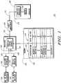
- FIG. 1is an electronic block diagram of a portable electronic device 100.
- the portable electronic device 100for example, can be a mobile cellular telephone, a mobile radio data terminal, a mobile cellular telephone having an attached data terminal, a personal computer, a personal digital assistant, or a two way messaging device.
- the term "portable electronic device”refers to any of the devices mentioned above or an equivalent.
- the portable electronic device 100includes a processor 105, a memory 120, and a vibrator 175.
- the processor 105is coupled to the memory 120, which can include a random access memory (RAM), a read-only memory (ROM), and an electrically erasable programmable read-only memory (EEPROM)(not shown).
- RAMrandom access memory
- ROMread-only memory
- EEPROMelectrically erasable programmable read-only memory
- the memory 120can be integrated within the portable electronic device 100, or alternatively can be at least partially contained within an external memory such as a subscriber identification module (SIM) card mechanically interconnected to the portable electronic device 100.
- SIMsubscriber identification module
- a SIM cardis an electronic device typically including a microprocessor unit and a memory suitable for encapsulating within a small flexible plastic card.
- the SIM cardadditionally includes some form of interface for communicating with an external device or system.
- the SIM cardcan be used to transfer a variety of information from/to the portable electronic device 100 and/or any other compatible device.
- a drive voltage memory 125is stored with the memory 120.
- the drive voltage memory 125can be stored within an internal memory, an external memory, or a combination therein.
- the drive voltage memory 125preferably stores a plurality of predetermined drive voltages 135 associated a plurality of identifications 130.
- a Battery A identificationhas a drive voltage V1 associated and stored therewith.
- an Accessory A identificationhas a drive voltage V4 associated and stored therewith.
- the processor 105includes a vibration control manager 110.
- the vibration control manager 110can be external to and electronically coupled to the processor 105.
- the vibration control manager 110can be hard coded or programmed into the portable electronic device 100 during manufacturing, can be programmed over-the-air upon customer subscription, or can be a downloadable application. It will be appreciated that other programming methods can be utilized for programming the vibration control manager 110 into the portable electronic device 100. It will be further appreciated by one of ordinary skill in the art that the vibration control manager 110 can be hardware circuitry within the portable electronic device 100 including being integrated within the processor 105.
- the vibration control manager 110operates using a plurality of rules which can be manually set by the user of the portable electronic device 100, can be preprogrammed into the portable electronic device 100, or can be programmed into the portable electronic device 100 by an administrator.
- the plurality of rulescan be changed as desired by the user and/or administrator.
- the plurality of rulesfor example, can include identifying a vibrator drive voltage associated with a detected accessory or battery identification using the data stored in the drive voltage memory 125.
- a battery interface 155is preferably coupled to the vibration control manager 110.
- the battery interface 155provides mechanical and electrical coupling of a battery 190 to the portable electronic device 100.
- the battery interface 150Upon detection of a connected battery 190, the battery interface 150 provides a battery signal 155 to the vibration control manager 110.
- the battery signal 155comprises a battery identification.
- the vibration control manager 110can retrieve the associated drive voltage for the battery identification from the drive voltage memory 125.
- the battery signal 155can include the drive voltage directly or some other associated battery information.
- the vibration control manager 110can query the connected battery 190 via the battery interface 150 to determine the battery identification and/or other battery parameters. For example, the vibration control manager 110 can identify the type of battery by reading an EPROM table which is embedded in the battery 190. Other methods such as mechanical keying or resister coding can also be used to identify the battery identification.
- An accessory interface 140is preferably coupled to the vibration control manager 110.
- the accessory interface 140provides mechanical and electrical coupling of one or more accessories to the portable electronic device 100.
- the accessory interface 140Upon detection of a connected accessory 195, the accessory interface 140 provides an accessory signal 145 to the vibration control manager 110.
- the accessory signal 145comprises an accessory identification.
- the vibration control manager 110can retrieve the associated drive voltage for the accessory identification from the drive voltage memory 125.
- the accessory signal 145can include the drive voltage directly or some other associated accessory information.
- the vibration control manager 110can query the connected accessory 195 via the accessory interface 140 to determine the accessory identification and/or other accessory parameters. For example, the vibration control manager 110 can identify the type of accessory by accessing a memory embedded in the accessory 195. Other methods such as mechanical keying or resister coding can also be used to identify the accessory identification.
- the vibration control manager 110can either determine a required drive voltage directly from the accessory 195 and/or battery 190, by querying the drive voltage memory 125, or by a predetermined algorithmic method which relates battery identification to required vibrator drive voltage.
- the vibration control manager 110is further coupled to a power management block 165. Upon detection of a new drive voltage, the vibration control manager 110 sends a command 160 to the power management block 165 including the new drive voltage to be utilized.
- the power management block 165is further coupled to the vibrator 175 which comprises a vibration generator 180 and a weight 185. It will be appreciated by those of ordinary skill in the art that the vibrator 175 can alternatively comprise any electromagnetic or piezo electric driven rotary or linear device with an offset weight to generate a vibratory sensory pulse.
- the power management block 165in response to the command 160, generates and provides a drive voltage 170 to the vibrator 175.
- the vibration control manager 110is able to drive or cause the power management block 165 to operate the vibrator 175 at the correct voltage, thereby causing a tactile sensation which has been optimized to the new product mass resulting from the change in battery mass and/or accessory mass.
- the processor 105Upon receipt and processing of a message or a call, or upon expiration of a timer or alarm, the processor 105 preferably generates a command signal to the vibrator 175 as a notification that the message has been received and stored, that a call is waiting for a response, or that a timer or alarm has expired.
- the vibrator 175thereafter responds by producing a physical vibration using the provided drive voltage 170 from the power management block 165.
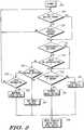
- FIG. 2is a flowchart illustrating one embodiment of the operation of the portable electronic device 100. Specifically, FIG. 2 illustrates the operation of the vibration control manager 110 in accordance with the present invention. As illustrated, the operation begins with Step 200 in which the portable electronic device 100 is in standby operation mode. Next, in Step 205, the vibration control manager 110 determines whether or not a battery change via the battery interface 150 has been detected.
- a battery changefor example, can be a removal of a battery, an attachment of a battery, or any combination therewith.
- Step 210the vibration control manager 110 determines whether or not an accessory change via the accessory interface 140 has been detected.
- An accessory changefor example, can be a removal of an accessory, an attachment of an accessory, or any combination therewith.
- the operationcycles back to Step 205 and periodically checks for a battery change.
- Step 215the vibration control manager 110 determines whether or not an identification has been received.
- the identificationfor example, can be a battery identification received via the battery interface 150 or an accessory identification received via the accessory interface 140.
- Step 220the vibration control manager 110 queries the new battery or the new accessory for the identification.
- Step 225the vibration control manager 110 determines whether the received identification is stored in the drive voltage memory 125.
- Step 225When the identification is stored in the drive voltage memory 125 in Step 225, the operation continues to Step 230 in which the associated drive voltage is retrieved from the drive voltage memory 125. When the identification is not stored in the drive voltage memory in Step 225, the operation continues to Step 235 in which the drive voltage is calculated using preprogrammed rules and/or algorithms in the vibration control manager 110.
- Step 240the vibration control manager 110 determines whether a drive voltage has been received.
- the drive voltage for a changed batterycan be received or alternatively obtained directly via the battery interface 150 from the attached battery.
- the drive voltage for a changed accessorycan be received or alternatively obtained directly via the accessory interface 140 from the attached accessory.
- Step 260the drive voltage is set to the received and/or obtained drive voltage.
- Step 245the vibration control manager 110 determines whether any other information which can be used to determine the drive voltage is available.
- the operationreturns to Step 205 and periodically checks for a battery change.
- Step 250the operation continues to Step 250 in which the vibration control manager 110 determines the drive voltage using the other information.
- Step 255the operation continues to Step 255 in which the vibrator 175 is driven using the new drive voltage as described previously herein for FIG. 1 .
- the operation of the present inventionprovides a method for automatically adjusting motor vibration strength based on the detection of mass lost or gained when a battery or other accessory device (such as a speaker or a dongle) is attached or removed. It uses identification data to automatically adjust vibration strength.
- the present inventionprovides a method and apparatus for compensating for changes in the weight and/or size of an attached battery and/or accessory within a portable electronic device. For example, when the radio vibration is optimized to the lightest battery pack or accessory, then any weight added by heavier battery packs or accessories reduces the vibration force.
- the present inventionprovides for increasing the drive voltage to the vibrator to compensate for vibration amplitude loss with only a slight decrease to the battery life. Similarly, when the radio vibration is optimized to the heaviest battery pack or accessory, then any weight loss by a lighter battery packs or accessories increases the vibration amplitude.
- the present inventionprovides for reducing the voltage to the vibrator to compensate for the lower weight with a slight increase in battery life.
Landscapes
- Engineering & Computer Science (AREA)
- Power Engineering (AREA)
- Mobile Radio Communication Systems (AREA)
- Telephone Function (AREA)
- Power Sources (AREA)
- Apparatuses For Generation Of Mechanical Vibrations (AREA)
Description
- This invention relates generally to the field of portable electronic devices capable of generating vibratory alerts.
- Many portable electronic devices utilize a tactile alert (i.e. vibratory alert) to alert the user of alarms, errors, or incoming data, messages, or calls. The vibrator, upon activation, generates vibrations which are transferred to the portable electronic device housing causing the device housing to shake, thereby alerting the user.
- Typically, a vibrator mechanism is an electromagnetic or piezo electric driven rotary or linear device with an off set weight to generate a vibratory sensory pulse. When the portable electronic device is positioned against the user's body, such as by placement in a shirt pocket or hung from a belt, the vibration alerts the user without others hearing the alert. This silent alert is particularly advantageous in meetings, in libraries, in offices where a lot of people share common space and other places where it may be inappropriate to use an audio alert.
- Some portable electronic devices today have interchangeable battery packs that allow the end user to trade up to a thicker/heavier device for more battery life (or visa versa). One drawback to this battery pack flexibility is that since the vibrator motor strength (normally proportional to vibrator motor speed) is optimized to one particular battery pack (with its own specific mass), suboptimal vibration performance is observed when thicker (and/or heavier) battery packs are installed. An example of prior art can be found in
EP1367687 . - The accompanying figures, where like reference numerals refer to identical or functionally similar elements throughout the separate views and which together with the detailed description below, are incorporated in and form part of the specification, serve to further illustrate various embodiments and to explain various principles and advantages all in accordance with the present invention.
FIG. 1 is an electronic block diagram of a portable electronic device.FIG. 2 is a flowchart illustrating one embodiment of the operation of the portable electronic device.- The present invention provides a method and apparatus within a portable electronic device for automatically adjusting vibration strength based on the detection of mass lost or gained when an accessory device (such as a battery or dongle) is attached or removed. It uses identification (ID) data to auto-adjust vibration strength.
FIG. 1 is an electronic block diagram of a portableelectronic device 100. The portableelectronic device 100, for example, can be a mobile cellular telephone, a mobile radio data terminal, a mobile cellular telephone having an attached data terminal, a personal computer, a personal digital assistant, or a two way messaging device. In the following description, the term "portable electronic device" refers to any of the devices mentioned above or an equivalent. As illustrated inFIG. 1 , the portableelectronic device 100 includes aprocessor 105, amemory 120, and avibrator 175.- To perform the necessary functions of the portable
electronic device 100, theprocessor 105 is coupled to thememory 120, which can include a random access memory (RAM), a read-only memory (ROM), and an electrically erasable programmable read-only memory (EEPROM)(not shown). It will be appreciated by those of ordinary skill in the art that thememory 120 can be integrated within the portableelectronic device 100, or alternatively can be at least partially contained within an external memory such as a subscriber identification module (SIM) card mechanically interconnected to the portableelectronic device 100. A SIM card is an electronic device typically including a microprocessor unit and a memory suitable for encapsulating within a small flexible plastic card. The SIM card additionally includes some form of interface for communicating with an external device or system. The SIM card can be used to transfer a variety of information from/to the portableelectronic device 100 and/or any other compatible device. - In accordance with the present invention, a
drive voltage memory 125 is stored with thememory 120. As described previously herein, thedrive voltage memory 125 can be stored within an internal memory, an external memory, or a combination therein. Thedrive voltage memory 125 preferably stores a plurality ofpredetermined drive voltages 135 associated a plurality ofidentifications 130. For example, as illustrated inFIG. 1 , a Battery A identification has a drive voltage V1 associated and stored therewith. Similarly, an Accessory A identification has a drive voltage V4 associated and stored therewith. - The
processor 105 includes avibration control manager 110. Alternatively, thevibration control manager 110 can be external to and electronically coupled to theprocessor 105. Thevibration control manager 110 can be hard coded or programmed into the portableelectronic device 100 during manufacturing, can be programmed over-the-air upon customer subscription, or can be a downloadable application. It will be appreciated that other programming methods can be utilized for programming thevibration control manager 110 into the portableelectronic device 100. It will be further appreciated by one of ordinary skill in the art that thevibration control manager 110 can be hardware circuitry within the portableelectronic device 100 including being integrated within theprocessor 105. - The
vibration control manager 110 operates using a plurality of rules which can be manually set by the user of the portableelectronic device 100, can be preprogrammed into the portableelectronic device 100, or can be programmed into the portableelectronic device 100 by an administrator. Preferably, the plurality of rules can be changed as desired by the user and/or administrator. The plurality of rules, for example, can include identifying a vibrator drive voltage associated with a detected accessory or battery identification using the data stored in thedrive voltage memory 125. - A
battery interface 155 is preferably coupled to thevibration control manager 110. Thebattery interface 155 provides mechanical and electrical coupling of abattery 190 to the portableelectronic device 100. Upon detection of a connectedbattery 190, thebattery interface 150 provides abattery signal 155 to thevibration control manager 110. In one embodiment, thebattery signal 155 comprises a battery identification. Upon receipt of thebattery signal 155, thevibration control manager 110 can retrieve the associated drive voltage for the battery identification from thedrive voltage memory 125. Alternatively, thebattery signal 155 can include the drive voltage directly or some other associated battery information. In an alternative embodiment, thevibration control manager 110 can query the connectedbattery 190 via thebattery interface 150 to determine the battery identification and/or other battery parameters. For example, thevibration control manager 110 can identify the type of battery by reading an EPROM table which is embedded in thebattery 190. Other methods such as mechanical keying or resister coding can also be used to identify the battery identification. - An
accessory interface 140 is preferably coupled to thevibration control manager 110. Theaccessory interface 140 provides mechanical and electrical coupling of one or more accessories to the portableelectronic device 100. Upon detection of a connectedaccessory 195, theaccessory interface 140 provides anaccessory signal 145 to thevibration control manager 110. In one embodiment, theaccessory signal 145 comprises an accessory identification. Upon receipt of theaccessory signal 145, thevibration control manager 110 can retrieve the associated drive voltage for the accessory identification from thedrive voltage memory 125. Alternatively, theaccessory signal 145 can include the drive voltage directly or some other associated accessory information. In an alternative embodiment, thevibration control manager 110 can query the connectedaccessory 195 via theaccessory interface 140 to determine the accessory identification and/or other accessory parameters. For example, thevibration control manager 110 can identify the type of accessory by accessing a memory embedded in theaccessory 195. Other methods such as mechanical keying or resister coding can also be used to identify the accessory identification. - Using the various methods described previously herein, the
vibration control manager 110 can either determine a required drive voltage directly from theaccessory 195 and/orbattery 190, by querying thedrive voltage memory 125, or by a predetermined algorithmic method which relates battery identification to required vibrator drive voltage. - The
vibration control manager 110 is further coupled to apower management block 165. Upon detection of a new drive voltage, thevibration control manager 110 sends acommand 160 to thepower management block 165 including the new drive voltage to be utilized. Thepower management block 165 is further coupled to thevibrator 175 which comprises avibration generator 180 and aweight 185. It will be appreciated by those of ordinary skill in the art that thevibrator 175 can alternatively comprise any electromagnetic or piezo electric driven rotary or linear device with an offset weight to generate a vibratory sensory pulse. Thepower management block 165, in response to thecommand 160, generates and provides adrive voltage 170 to thevibrator 175. In this manner, thevibration control manager 110 is able to drive or cause thepower management block 165 to operate thevibrator 175 at the correct voltage, thereby causing a tactile sensation which has been optimized to the new product mass resulting from the change in battery mass and/or accessory mass. - Upon receipt and processing of a message or a call, or upon expiration of a timer or alarm, the
processor 105 preferably generates a command signal to thevibrator 175 as a notification that the message has been received and stored, that a call is waiting for a response, or that a timer or alarm has expired. Thevibrator 175 thereafter responds by producing a physical vibration using the provideddrive voltage 170 from thepower management block 165. FIG. 2 is a flowchart illustrating one embodiment of the operation of the portableelectronic device 100. Specifically,FIG. 2 illustrates the operation of thevibration control manager 110 in accordance with the present invention. As illustrated, the operation begins withStep 200 in which the portableelectronic device 100 is in standby operation mode. Next, inStep 205, thevibration control manager 110 determines whether or not a battery change via thebattery interface 150 has been detected. A battery change, for example, can be a removal of a battery, an attachment of a battery, or any combination therewith. When no battery change has been detected inStep 205, the operation continues withStep 210 in which thevibration control manager 110 determines whether or not an accessory change via theaccessory interface 140 has been detected. An accessory change, for example, can be a removal of an accessory, an attachment of an accessory, or any combination therewith. When no accessory change is detected inStep 210, the operation cycles back toStep 205 and periodically checks for a battery change.- When a battery change is detected in
Step 205 or an accessory change is detected inStep 210, the operation continues withStep 215 in which thevibration control manager 110 determines whether or not an identification has been received. The identification, for example, can be a battery identification received via thebattery interface 150 or an accessory identification received via theaccessory interface 140. When no identification has been received, the operation continues to Step 220 in which thevibration control manager 110 queries the new battery or the new accessory for the identification. When the query ofStep 220 results in the new identification or the identification is received inStep 215, the operation continues to Step 225 in which thevibration control manager 110 determines whether the received identification is stored in thedrive voltage memory 125. When the identification is stored in thedrive voltage memory 125 inStep 225, the operation continues to Step 230 in which the associated drive voltage is retrieved from thedrive voltage memory 125. When the identification is not stored in the drive voltage memory inStep 225, the operation continues to Step 235 in which the drive voltage is calculated using preprogrammed rules and/or algorithms in thevibration control manager 110. - Returning to Step 220, when no identification is available via query, the operation continues to Step 240 in which the
vibration control manager 110 determines whether a drive voltage has been received. For example, the drive voltage for a changed battery can be received or alternatively obtained directly via thebattery interface 150 from the attached battery. Similarly, the drive voltage for a changed accessory can be received or alternatively obtained directly via theaccessory interface 140 from the attached accessory. When the drive voltage has been received, the operation continues to Step 260 in which the drive voltage is set to the received and/or obtained drive voltage. When no drive voltage has been received and/or obtained inStep 240, the operation continues to Step 245, in which thevibration control manager 110 determines whether any other information which can be used to determine the drive voltage is available. When no other information is available, the operation returns to Step 205 and periodically checks for a battery change. When other information is available inStep 245, the operation continues to Step 250 in which thevibration control manager 110 determines the drive voltage using the other information. - After
Steps vibrator 175 is driven using the new drive voltage as described previously herein forFIG. 1 . - The operation of the present invention, as described herein provides a method for automatically adjusting motor vibration strength based on the detection of mass lost or gained when a battery or other accessory device (such as a speaker or a dongle) is attached or removed. It uses identification data to automatically adjust vibration strength.
- The present invention provides a method and apparatus for compensating for changes in the weight and/or size of an attached battery and/or accessory within a portable electronic device. For example, when the radio vibration is optimized to the lightest battery pack or accessory, then any weight added by heavier battery packs or accessories reduces the vibration force. The present invention provides for increasing the drive voltage to the vibrator to compensate for vibration amplitude loss with only a slight decrease to the battery life. Similarly, when the radio vibration is optimized to the heaviest battery pack or accessory, then any weight loss by a lighter battery packs or accessories increases the vibration amplitude. The present invention provides for reducing the voltage to the vibrator to compensate for the lower weight with a slight increase in battery life.
- While this disclosure includes what are considered presently to be the preferred embodiments and best modes of the invention described in a manner that establishes possession thereof by the inventors and that enables those of ordinary skill in the art to make and use the invention, it will be understood and appreciated that there are many equivalents to the preferred embodiments disclosed herein and that modifications and variations may be made without departing from the scope of the invention, which are to be limited not by the preferred embodiments but by the appended claims, including any amendments made during the pendency of this application and all equivalents of those claims as issued.
- It is further understood that the use of relational terms such as first and second, top and bottom, and the like, if any, are used solely to distinguish one from another entity, item, or action without necessarily requiring or implying any actual such relationship or order between such entities, items or actions. Much of the inventive functionality and many of the inventive principles are best implemented with or in software programs or instructions. It is expected that one of ordinary skill, notwithstanding possibly significant effort and many design choices motivated by, for example, available time, current technology, and economic considerations, when guided by the concepts and principles disclosed herein will be readily capable of generating such software instructions and programs with minimal experimentation. Therefore, further discussion of such software, if any, will be limited in the interest of brevity and minimization of any risk of obscuring the principles and concepts according to the present invention.
Claims (8)
- A method of operation of a portable electronic device comprising the steps of:detecting an attached device that is associated with a drive voltage;determining an identification of the attached device, wherein the method ischaracterized by:selecting the drive voltage with which the attached device is associated using the identification of the attached device; anddriving a vibrator using the selected drive voltage associated with the identification of the attached device.
- A method of operation as recited in claim 1, wherein the detecting step comprises detecting an attached battery.
- A method of operation as recited in claim 1, wherein the detecting step comprises detecting an attached accessory.
- A method of operation as recited in claim 1, wherein the determining step comprises the step of:receiving the identification from the attached device.
- A method of operation as recited in claim 1, wherein the determining step comprises the step of:querying the attached device to obtain the identification.
- A method of operation as recited in claim 1, wherein the selecting step comprises the step of:retrieving the drive voltage from a memory in which the identification and the drive voltage are stored.
- A method of operation of a portable electronic device as recited in claim 1 wherein the selecting step comprises the step of:calculating the drive voltage from the identification.
- A portable electronic device comprising:an attached device;a vibrator;a memory that includes drive voltage values, each drive voltage value associated with a device identification; anda processor coupled between the attached device and the vibrator, the processor adapted to:detect the attached device,determine an identification for the attached device,select a drive voltage from the drive voltage values with the identification of the attached device, anddrive the vibrator using the drive voltage selected with the identification of the attached device.
Applications Claiming Priority (2)
| Application Number | Priority Date | Filing Date | Title |
|---|---|---|---|
| US10/903,541US7088256B2 (en) | 2004-07-30 | 2004-07-30 | Portable electronic device and method of operation therefore |
| PCT/US2005/026431WO2006014922A2 (en) | 2004-07-30 | 2005-07-26 | Portable electronic device and method of operation therefore |
Publications (3)
| Publication Number | Publication Date |
|---|---|
| EP1774671A2 EP1774671A2 (en) | 2007-04-18 |
| EP1774671A4 EP1774671A4 (en) | 2010-06-30 |
| EP1774671B1true EP1774671B1 (en) | 2019-02-13 |
Family
ID=35731496
Family Applications (1)
| Application Number | Title | Priority Date | Filing Date |
|---|---|---|---|
| EP05775462.4AExpired - LifetimeEP1774671B1 (en) | 2004-07-30 | 2005-07-26 | Portable electronic device and method of operation therefore |
Country Status (6)
| Country | Link |
|---|---|
| US (1) | US7088256B2 (en) |
| EP (1) | EP1774671B1 (en) |
| KR (1) | KR101068362B1 (en) |
| CN (1) | CN101002399B (en) |
| MX (1) | MX2007001158A (en) |
| WO (1) | WO2006014922A2 (en) |
Families Citing this family (6)
| Publication number | Priority date | Publication date | Assignee | Title |
|---|---|---|---|---|
| US20090259359A1 (en)* | 2008-04-09 | 2009-10-15 | David Michael Whitton | Variable intensity haptic level control based on vehicle conditions |
| US8909173B2 (en) | 2012-06-29 | 2014-12-09 | Motorola Solutions, Inc. | Method and apparatus for operating accessory interface functions over a single signal |
| US10613213B2 (en)* | 2016-05-13 | 2020-04-07 | Google Llc | Systems, methods, and devices for utilizing radar with smart devices |
| US10687184B2 (en) | 2016-05-13 | 2020-06-16 | Google Llc | Systems, methods, and devices for utilizing radar-based touch interfaces |
| US10755676B2 (en) | 2018-03-15 | 2020-08-25 | Magic Leap, Inc. | Image correction due to deformation of components of a viewing device |
| JP7330715B2 (en)* | 2018-04-03 | 2023-08-22 | キヤノン株式会社 | ELECTRONIC DEVICE, CONTROL METHOD AND PROGRAM FOR ELECTRONIC DEVICE |
Family Cites Families (10)
| Publication number | Priority date | Publication date | Assignee | Title |
|---|---|---|---|---|
| US4441098A (en)* | 1981-04-06 | 1984-04-03 | Motorola, Inc. | Multiposition switch with minimum interconnections |
| US4965532A (en)* | 1988-06-17 | 1990-10-23 | Olympus Optical Co., Ltd. | Circuit for driving ultrasonic transducer |
| US5151085A (en)* | 1989-04-28 | 1992-09-29 | Olympus Optical Co., Ltd. | Apparatus for generating ultrasonic oscillation |
| KR950013305B1 (en)* | 1992-11-10 | 1995-11-02 | 삼성전자주식회사 | The paging receiver |
| US5792138A (en)* | 1996-02-22 | 1998-08-11 | Apollo Camera, Llc | Cordless bipolar electrocautery unit with automatic power control |
| US6104512A (en)* | 1998-01-23 | 2000-08-15 | Motorola, Inc. | Method for adjusting the power level of an infrared signal |
| JP3721888B2 (en)* | 1998-12-04 | 2005-11-30 | セイコーエプソン株式会社 | Portable electronic device and method for controlling portable electronic device |
| TW592761B (en)* | 2000-05-24 | 2004-06-21 | Nintendo Co Ltd | Game system, game cartridge and game machine |
| US6785829B1 (en)* | 2000-06-30 | 2004-08-31 | Intel Corporation | Multiple operating frequencies in a processor |
| US6744698B2 (en)* | 2001-03-08 | 2004-06-01 | Seiko Epson Corporation | Battery powered electronic device and control method therefor |
- 2004
- 2004-07-30USUS10/903,541patent/US7088256B2/ennot_activeExpired - Lifetime
- 2005
- 2005-07-26MXMX2007001158Apatent/MX2007001158A/enactiveIP Right Grant
- 2005-07-26CNCN200580025282XApatent/CN101002399B/ennot_activeExpired - Fee Related
- 2005-07-26KRKR1020077002378Apatent/KR101068362B1/ennot_activeExpired - Lifetime
- 2005-07-26EPEP05775462.4Apatent/EP1774671B1/ennot_activeExpired - Lifetime
- 2005-07-26WOPCT/US2005/026431patent/WO2006014922A2/enactiveApplication Filing
Non-Patent Citations (1)
| Title |
|---|
| None* |
Also Published As
| Publication number | Publication date |
|---|---|
| WO2006014922A3 (en) | 2006-05-26 |
| KR101068362B1 (en) | 2011-09-28 |
| WO2006014922B1 (en) | 2006-07-13 |
| US20060022807A1 (en) | 2006-02-02 |
| EP1774671A2 (en) | 2007-04-18 |
| MX2007001158A (en) | 2007-04-19 |
| CN101002399A (en) | 2007-07-18 |
| WO2006014922A2 (en) | 2006-02-09 |
| EP1774671A4 (en) | 2010-06-30 |
| US7088256B2 (en) | 2006-08-08 |
| KR20070045213A (en) | 2007-05-02 |
| CN101002399B (en) | 2011-06-08 |
Similar Documents
| Publication | Publication Date | Title |
|---|---|---|
| US8077019B2 (en) | Method of associating groups of classified source addresses with vibration patterns | |
| US5649020A (en) | Electronic driver for an electromagnetic resonant transducer | |
| US6973336B2 (en) | Method and apparatus for providing a notification of received message | |
| CN1169336C (en) | System for alerting portable communication device user of incoming call | |
| US7439872B2 (en) | Method and mobile device for non-visually signaling the state of a mobile device | |
| US6782251B2 (en) | Method and apparatus for operating a lost mobile communication device | |
| US5524061A (en) | Dual mode transducer for a portable receiver | |
| CN1139281C (en) | Closable communication device and method of operation thereof | |
| US8923804B1 (en) | Notification device for cellular telephone | |
| US6226536B1 (en) | Charger capable of controlling alerting means and radio equipment consisting of the charger and a portable radio apparatus | |
| EP0838908B1 (en) | Radiotelephone proximity detector | |
| KR20010039652A (en) | Battery charging system for portable electronic devices | |
| US20010029196A1 (en) | Battery-powered mobile phone having additional functions | |
| KR20060056968A (en) | Communication device with intelligent communication management and method therefor | |
| CN1072886C (en) | Standby operation in a wireless communication device | |
| US20040214594A1 (en) | Device having smart user alert | |
| EP1774671B1 (en) | Portable electronic device and method of operation therefore | |
| WO2003003599A2 (en) | Mobile communication device emergency power management method and apparatus | |
| JP5353062B2 (en) | Electronics | |
| JP3263632B2 (en) | Communication equipment and its adjusting device | |
| KR100290130B1 (en) | Call signal notification method of wireless communication device | |
| JP2001036611A (en) | Radio communication unit | |
| KR20080068962A (en) | Alarm Control Method of Mobile Terminal | |
| KR20060069919A (en) | Battery authentication system and method of mobile communication terminal | |
| JP2004328245A (en) | Mobile phone terminal, setting change method therefor, and program therefor |
Legal Events
| Date | Code | Title | Description |
|---|---|---|---|
| PUAI | Public reference made under article 153(3) epc to a published international application that has entered the european phase | Free format text:ORIGINAL CODE: 0009012 | |
| 17P | Request for examination filed | Effective date:20070228 | |
| AK | Designated contracting states | Kind code of ref document:A2 Designated state(s):AT BE BG CH CY CZ DE DK EE ES FI FR GB GR HU IE IS IT LI LT LU LV MC NL PL PT RO SE SI SK TR | |
| RIN1 | Information on inventor provided before grant (corrected) | Inventor name:WONG, YUN, YEE Inventor name:ROLLINS, THOMAS, J. Inventor name:OPELA, PETER, S. | |
| DAX | Request for extension of the european patent (deleted) | ||
| A4 | Supplementary search report drawn up and despatched | Effective date:20100528 | |
| RIC1 | Information provided on ipc code assigned before grant | Ipc:H02J 7/00 20060101AFI20100521BHEP | |
| RAP1 | Party data changed (applicant data changed or rights of an application transferred) | Owner name:MOTOROLA MOBILITY, INC. | |
| RAP1 | Party data changed (applicant data changed or rights of an application transferred) | Owner name:MOTOROLA MOBILITY LLC | |
| 17Q | First examination report despatched | Effective date:20140527 | |
| RAP1 | Party data changed (applicant data changed or rights of an application transferred) | Owner name:GOOGLE TECHNOLOGY HOLDINGS LLC | |
| STAA | Information on the status of an ep patent application or granted ep patent | Free format text:STATUS: EXAMINATION IS IN PROGRESS | |
| GRAP | Despatch of communication of intention to grant a patent | Free format text:ORIGINAL CODE: EPIDOSNIGR1 | |
| STAA | Information on the status of an ep patent application or granted ep patent | Free format text:STATUS: GRANT OF PATENT IS INTENDED | |
| INTG | Intention to grant announced | Effective date:20180726 | |
| GRAJ | Information related to disapproval of communication of intention to grant by the applicant or resumption of examination proceedings by the epo deleted | Free format text:ORIGINAL CODE: EPIDOSDIGR1 | |
| STAA | Information on the status of an ep patent application or granted ep patent | Free format text:STATUS: EXAMINATION IS IN PROGRESS | |
| GRAP | Despatch of communication of intention to grant a patent | Free format text:ORIGINAL CODE: EPIDOSNIGR1 | |
| STAA | Information on the status of an ep patent application or granted ep patent | Free format text:STATUS: GRANT OF PATENT IS INTENDED | |
| INTC | Intention to grant announced (deleted) | ||
| INTG | Intention to grant announced | Effective date:20181024 | |
| GRAS | Grant fee paid | Free format text:ORIGINAL CODE: EPIDOSNIGR3 | |
| GRAA | (expected) grant | Free format text:ORIGINAL CODE: 0009210 | |
| STAA | Information on the status of an ep patent application or granted ep patent | Free format text:STATUS: THE PATENT HAS BEEN GRANTED | |
| AK | Designated contracting states | Kind code of ref document:B1 Designated state(s):AT BE BG CH CY CZ DE DK EE ES FI FR GB GR HU IE IS IT LI LT LU LV MC NL PL PT RO SE SI SK TR | |
| REG | Reference to a national code | Ref country code:GB Ref legal event code:FG4D | |
| REG | Reference to a national code | Ref country code:CH Ref legal event code:EP Ref country code:AT Ref legal event code:REF Ref document number:1096758 Country of ref document:AT Kind code of ref document:T Effective date:20190215 | |
| REG | Reference to a national code | Ref country code:IE Ref legal event code:FG4D | |
| REG | Reference to a national code | Ref country code:DE Ref legal event code:R096 Ref document number:602005055374 Country of ref document:DE | |
| REG | Reference to a national code | Ref country code:LT Ref legal event code:MG4D | |
| REG | Reference to a national code | Ref country code:NL Ref legal event code:MP Effective date:20190213 | |
| PG25 | Lapsed in a contracting state [announced via postgrant information from national office to epo] | Ref country code:NL Free format text:LAPSE BECAUSE OF FAILURE TO SUBMIT A TRANSLATION OF THE DESCRIPTION OR TO PAY THE FEE WITHIN THE PRESCRIBED TIME-LIMIT Effective date:20190213 Ref country code:SE Free format text:LAPSE BECAUSE OF FAILURE TO SUBMIT A TRANSLATION OF THE DESCRIPTION OR TO PAY THE FEE WITHIN THE PRESCRIBED TIME-LIMIT Effective date:20190213 Ref country code:FI Free format text:LAPSE BECAUSE OF FAILURE TO SUBMIT A TRANSLATION OF THE DESCRIPTION OR TO PAY THE FEE WITHIN THE PRESCRIBED TIME-LIMIT Effective date:20190213 Ref country code:PT Free format text:LAPSE BECAUSE OF FAILURE TO SUBMIT A TRANSLATION OF THE DESCRIPTION OR TO PAY THE FEE WITHIN THE PRESCRIBED TIME-LIMIT Effective date:20190613 Ref country code:LT Free format text:LAPSE BECAUSE OF FAILURE TO SUBMIT A TRANSLATION OF THE DESCRIPTION OR TO PAY THE FEE WITHIN THE PRESCRIBED TIME-LIMIT Effective date:20190213 | |
| PG25 | Lapsed in a contracting state [announced via postgrant information from national office to epo] | Ref country code:IS Free format text:LAPSE BECAUSE OF FAILURE TO SUBMIT A TRANSLATION OF THE DESCRIPTION OR TO PAY THE FEE WITHIN THE PRESCRIBED TIME-LIMIT Effective date:20190613 Ref country code:GR Free format text:LAPSE BECAUSE OF FAILURE TO SUBMIT A TRANSLATION OF THE DESCRIPTION OR TO PAY THE FEE WITHIN THE PRESCRIBED TIME-LIMIT Effective date:20190514 Ref country code:LV Free format text:LAPSE BECAUSE OF FAILURE TO SUBMIT A TRANSLATION OF THE DESCRIPTION OR TO PAY THE FEE WITHIN THE PRESCRIBED TIME-LIMIT Effective date:20190213 Ref country code:BG Free format text:LAPSE BECAUSE OF FAILURE TO SUBMIT A TRANSLATION OF THE DESCRIPTION OR TO PAY THE FEE WITHIN THE PRESCRIBED TIME-LIMIT Effective date:20190513 | |
| REG | Reference to a national code | Ref country code:AT Ref legal event code:MK05 Ref document number:1096758 Country of ref document:AT Kind code of ref document:T Effective date:20190213 | |
| PG25 | Lapsed in a contracting state [announced via postgrant information from national office to epo] | Ref country code:ES Free format text:LAPSE BECAUSE OF FAILURE TO SUBMIT A TRANSLATION OF THE DESCRIPTION OR TO PAY THE FEE WITHIN THE PRESCRIBED TIME-LIMIT Effective date:20190213 Ref country code:DK Free format text:LAPSE BECAUSE OF FAILURE TO SUBMIT A TRANSLATION OF THE DESCRIPTION OR TO PAY THE FEE WITHIN THE PRESCRIBED TIME-LIMIT Effective date:20190213 Ref country code:RO Free format text:LAPSE BECAUSE OF FAILURE TO SUBMIT A TRANSLATION OF THE DESCRIPTION OR TO PAY THE FEE WITHIN THE PRESCRIBED TIME-LIMIT Effective date:20190213 Ref country code:CZ Free format text:LAPSE BECAUSE OF FAILURE TO SUBMIT A TRANSLATION OF THE DESCRIPTION OR TO PAY THE FEE WITHIN THE PRESCRIBED TIME-LIMIT Effective date:20190213 Ref country code:IT Free format text:LAPSE BECAUSE OF FAILURE TO SUBMIT A TRANSLATION OF THE DESCRIPTION OR TO PAY THE FEE WITHIN THE PRESCRIBED TIME-LIMIT Effective date:20190213 Ref country code:EE Free format text:LAPSE BECAUSE OF FAILURE TO SUBMIT A TRANSLATION OF THE DESCRIPTION OR TO PAY THE FEE WITHIN THE PRESCRIBED TIME-LIMIT Effective date:20190213 Ref country code:SK Free format text:LAPSE BECAUSE OF FAILURE TO SUBMIT A TRANSLATION OF THE DESCRIPTION OR TO PAY THE FEE WITHIN THE PRESCRIBED TIME-LIMIT Effective date:20190213 | |
| REG | Reference to a national code | Ref country code:DE Ref legal event code:R097 Ref document number:602005055374 Country of ref document:DE | |
| PG25 | Lapsed in a contracting state [announced via postgrant information from national office to epo] | Ref country code:PL Free format text:LAPSE BECAUSE OF FAILURE TO SUBMIT A TRANSLATION OF THE DESCRIPTION OR TO PAY THE FEE WITHIN THE PRESCRIBED TIME-LIMIT Effective date:20190213 | |
| PLBE | No opposition filed within time limit | Free format text:ORIGINAL CODE: 0009261 | |
| STAA | Information on the status of an ep patent application or granted ep patent | Free format text:STATUS: NO OPPOSITION FILED WITHIN TIME LIMIT | |
| PG25 | Lapsed in a contracting state [announced via postgrant information from national office to epo] | Ref country code:AT Free format text:LAPSE BECAUSE OF FAILURE TO SUBMIT A TRANSLATION OF THE DESCRIPTION OR TO PAY THE FEE WITHIN THE PRESCRIBED TIME-LIMIT Effective date:20190213 | |
| 26N | No opposition filed | Effective date:20191114 | |
| PG25 | Lapsed in a contracting state [announced via postgrant information from national office to epo] | Ref country code:MC Free format text:LAPSE BECAUSE OF FAILURE TO SUBMIT A TRANSLATION OF THE DESCRIPTION OR TO PAY THE FEE WITHIN THE PRESCRIBED TIME-LIMIT Effective date:20190213 Ref country code:SI Free format text:LAPSE BECAUSE OF FAILURE TO SUBMIT A TRANSLATION OF THE DESCRIPTION OR TO PAY THE FEE WITHIN THE PRESCRIBED TIME-LIMIT Effective date:20190213 | |
| REG | Reference to a national code | Ref country code:CH Ref legal event code:PL | |
| PG25 | Lapsed in a contracting state [announced via postgrant information from national office to epo] | Ref country code:TR Free format text:LAPSE BECAUSE OF FAILURE TO SUBMIT A TRANSLATION OF THE DESCRIPTION OR TO PAY THE FEE WITHIN THE PRESCRIBED TIME-LIMIT Effective date:20190213 | |
| REG | Reference to a national code | Ref country code:BE Ref legal event code:MM Effective date:20190731 | |
| PG25 | Lapsed in a contracting state [announced via postgrant information from national office to epo] | Ref country code:LU Free format text:LAPSE BECAUSE OF NON-PAYMENT OF DUE FEES Effective date:20190726 Ref country code:BE Free format text:LAPSE BECAUSE OF NON-PAYMENT OF DUE FEES Effective date:20190731 Ref country code:CH Free format text:LAPSE BECAUSE OF NON-PAYMENT OF DUE FEES Effective date:20190731 Ref country code:LI Free format text:LAPSE BECAUSE OF NON-PAYMENT OF DUE FEES Effective date:20190731 | |
| PG25 | Lapsed in a contracting state [announced via postgrant information from national office to epo] | Ref country code:IE Free format text:LAPSE BECAUSE OF NON-PAYMENT OF DUE FEES Effective date:20190726 | |
| PGFP | Annual fee paid to national office [announced via postgrant information from national office to epo] | Ref country code:FR Payment date:20200728 Year of fee payment:16 | |
| PG25 | Lapsed in a contracting state [announced via postgrant information from national office to epo] | Ref country code:CY Free format text:LAPSE BECAUSE OF FAILURE TO SUBMIT A TRANSLATION OF THE DESCRIPTION OR TO PAY THE FEE WITHIN THE PRESCRIBED TIME-LIMIT Effective date:20190213 | |
| PG25 | Lapsed in a contracting state [announced via postgrant information from national office to epo] | Ref country code:HU Free format text:LAPSE BECAUSE OF FAILURE TO SUBMIT A TRANSLATION OF THE DESCRIPTION OR TO PAY THE FEE WITHIN THE PRESCRIBED TIME-LIMIT; INVALID AB INITIO Effective date:20050726 | |
| PG25 | Lapsed in a contracting state [announced via postgrant information from national office to epo] | Ref country code:FR Free format text:LAPSE BECAUSE OF NON-PAYMENT OF DUE FEES Effective date:20210731 | |
| P01 | Opt-out of the competence of the unified patent court (upc) registered | Effective date:20230511 | |
| PGFP | Annual fee paid to national office [announced via postgrant information from national office to epo] | Ref country code:GB Payment date:20230727 Year of fee payment:19 | |
| PGFP | Annual fee paid to national office [announced via postgrant information from national office to epo] | Ref country code:DE Payment date:20230727 Year of fee payment:19 | |
| REG | Reference to a national code | Ref country code:DE Ref legal event code:R119 Ref document number:602005055374 Country of ref document:DE | |
| GBPC | Gb: european patent ceased through non-payment of renewal fee | Effective date:20240726 | |
| PG25 | Lapsed in a contracting state [announced via postgrant information from national office to epo] | Ref country code:DE Free format text:LAPSE BECAUSE OF NON-PAYMENT OF DUE FEES Effective date:20250201 | |
| PG25 | Lapsed in a contracting state [announced via postgrant information from national office to epo] | Ref country code:GB Free format text:LAPSE BECAUSE OF NON-PAYMENT OF DUE FEES Effective date:20240726 |