EP1773804B1 - Sls for tooling applications - Google Patents
Sls for tooling applicationsDownload PDFInfo
- Publication number
- EP1773804B1 EP1773804B1EP05772019.5AEP05772019AEP1773804B1EP 1773804 B1EP1773804 B1EP 1773804B1EP 05772019 AEP05772019 AEP 05772019AEP 1773804 B1EP1773804 B1EP 1773804B1
- Authority
- EP
- European Patent Office
- Prior art keywords
- tool
- section
- feature
- sintering
- predetermining
- Prior art date
- Legal status (The legal status is an assumption and is not a legal conclusion. Google has not performed a legal analysis and makes no representation as to the accuracy of the status listed.)
- Expired - Lifetime
Links
Images

Classifications
- B—PERFORMING OPERATIONS; TRANSPORTING
- B29—WORKING OF PLASTICS; WORKING OF SUBSTANCES IN A PLASTIC STATE IN GENERAL
- B29C—SHAPING OR JOINING OF PLASTICS; SHAPING OF MATERIAL IN A PLASTIC STATE, NOT OTHERWISE PROVIDED FOR; AFTER-TREATMENT OF THE SHAPED PRODUCTS, e.g. REPAIRING
- B29C64/00—Additive manufacturing, i.e. manufacturing of three-dimensional [3D] objects by additive deposition, additive agglomeration or additive layering, e.g. by 3D printing, stereolithography or selective laser sintering
- B29C64/10—Processes of additive manufacturing
- B29C64/141—Processes of additive manufacturing using only solid materials
- B29C64/153—Processes of additive manufacturing using only solid materials using layers of powder being selectively joined, e.g. by selective laser sintering or melting
Definitions
- the present inventionrelates generally to tooling systems and processes and is more specifically related to the fabrication of tools through selective laser sintering.
- a manufacturing master model toolis a three-dimensional representation of a part or assembly.
- the master modelcontrols physical features and shapes during the manufacture or “build” of assembly tools, thereby ensuring that parts and assemblies created using the master model fit together.
- Master modelsmay be made from many different materials including: steel, aluminum, plaster, clay, and composites; and the selection of a specific material has been application dependent. Master models are usually hand-made and require skilled craftsmen to accurately capture the design intent. Once the master model exists, it may be used to duplicate tools.
- the master modelbecomes the master definition for the contours and edges of a part pattern that the master model represents.
- the engineering and tool model definitions of those featuresbecome reference only.
- Root cause analysis of issues within tool families associated with the masterhas required tool removal from production for tool fabrication coordination with the master. Tools must also be removed from production for master model coordination when repairing or replacing tool details. Further, the master must be stored and maintained for the life of the tool.
- Master modelsare costly in that they require design, modeling and surfacing, programming, machine time, hand work, secondary fabrication operations, and inspection prior to use in tool fabrication.
- Rapid prototypinggenerally refers to the manufacture of objects directly from computer-aided-design (CAD) databases in an automated fashion, rather than from conventional machining of prototype objects following engineering drawings.
- CADcomputer-aided-design
- SLSselective laser sintering process
- Conventional selective laser sintering systemsposition the laser beam by way of galvanometer-driven mirrors that deflect the laser beam.
- the deflection of the laser beamis controlled, in combination with modulation of the laser itself, for directing laser energy to those locations of the fusible powder layer corresponding to the cross-section of the object to be formed in that layer.
- the lasermay be scanned across the powder in a raster fashion or a vector fashion.
- cross-sections of objectsare formed in a powder layer by fusing powder along the outline of the cross-section in vector fashion either before or after a raster scan that fills the area within the vector-drawn outline.
- an additional layer of powderis then dispensed and the process repeated, with fused portions of later layers fusing to fused portions of previous layers (as appropriate for the object), until the object is completed.
- Selective laser sinteringhas enabled the direct manufacture of three-dimensional objects of high resolution and dimensional accuracy from a variety of materials including polystyrene, NYLON, other plastics, and composite materials, such as polymer coated metals and ceramics.
- selective laser sinteringmay be used for the direct fabrication of molds from a CAD database representation of the object in the fabricated molds.
- Selective Laser Sinteringhas, however, not been generally available for tool manufacture because of SLS part size limitations, lack if robustness of SLS objects, and inherent limitations in the SLS process.
- DE 10051893discloses components designed in a CAD system that are split into individual modules (7,8,9) which are then manufactured by first forming a base body (7a,8a,9a) which is placed in a laser sintering apparatus. A body (7b,8b,9b) is formed successively on the base body from a powder material by laser sintering, the body representing the difference between the base body and the final module. The resulting modules are assembled into a component.
- the disadvantages associated with current tool manufacturing systemshave made it apparent that a new and improved tooling system is needed.
- the new tooling systemshould reduce need for master models and should reduce time requirements and costs associated with tool manufacture.
- the new systemshould also apply SLS technology to tooling applications.
- the present inventionis directed to these ends.
- a system for manufacturing a tool within a laser sintering systemincludes a chamber enclosing a sinter material.
- the laser sintering systemgrows or sinters the tool from the sinter material in response to signals from a controller, which generates the signals as a function of a predetermined tool design.
- a heat sinkis positioned within the chamber to cool features of the tool thereby limiting warping of these features during sintering of the tool.
- a method for laser sintering a toolincludes predetermining a position for a tool feature on a tool section. The method further includes predetermining an orientation of the tool section within a part chamber as a function of minimizing warping of the tool feature during sintering. The tool section is then sintered within the part chamber.
- One advantage of the present inventionis that use of Selective Laser Sintering can significantly reduce costs and cycle time associated with the tool fabrication process.
- An additional advantageis that tool features can be "grown" as represented by the three-dimensional computer model, thus eliminating the requirement for a master model or facility detail. The subsequent maintenance or storage of the master/facility is thereby also eliminated.
- Still another advantage of the present inventionis that the model remains the master definition of the tool, therefore root cause analysis or detail replacement may be done directly from the model definition. Secondary fabrication operations are further eliminated where features are "grown" per the three-dimensional solid model definition.
- the present inventionis illustrated with respect to a sintering system particularly suited to the aerospace field.
- the present inventionis, however, applicable to various other uses that may require tooling or parts manufacture, as will be understood by one skilled in the art.
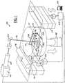
- FIGURE 1illustrates a selective laser sintering system 100 having a chamber 102 (the front doors and top of chamber 102 not shown in FIGURE 1 , for purposes of clarity).
- the chamber 102maintains the appropriate temperature and atmospheric composition (typically an inert atmosphere such as nitrogen) for the fabrication of a tool section 104.
- the system 100typically operates in response to signals from a controller 105 controlling, for example, motors 106 and 108, pistons 114 and 107, roller 118, laser 120, and mirrors 124, all of which are discussed below.
- the controller 105is typically controlled by a computer 125 or processor running; for example, a computer-aided design program (CAD) defining a cross-section of the tool section 102.
- CADcomputer-aided design program
- the system 100is further adjusted and controlled through various control features, such as the addition of heat sinks, optimal objection orientations, and feature placements, which are detailed herein.
- the chamber 102encloses a powder sinter material that is delivered therein through a powder delivery system.
- the powder delivery system in system 100includes feed piston 114, controlled by motor 106, moving upwardly and lifting a volume of powder into the chamber 102.
- Two powder feed and collection pistons 114may be provided on either side of part piston 107, for purposes of efficient and flexible powder delivery.
- Part piston 107is controlled by motor 108 for moving downwardly below the floor of chamber 102 (part cylinder or part chamber) by small amounts, for example 0.125 mm, thereby defining the thickness of each layer of powder undergoing processing.
- the roller 118is a counter-rotating roller that translates powder from feed piston 114 to target surface 115.
- Target surface 115refers to the top surface of heat-fusible powder (including portions previously sintered, if present) disposed above part piston 107; the sintered and unsintered powder disposed on part piston 107 and enclosed by the chamber 102 will be referred to herein as the part bed 117.
- Another known powder delivery systemfeeds powder from above part piston 107, in front of a delivery apparatus such as a roller or scraper.
- a laser beamis generated by the laser 120, and aimed at target surface 115 by way of a scanning system 122, generally including galvanometer-driven mirrors 124 deflecting the laser beam 126.
- the deflection of the laser beam 126is controlled, in combination with modulation of laser 120, for directing laser energy to those locations of the fusible powder layer corresponding to the cross-section of the tool section 104 formed in that layer.
- the scanning system 122may scan the laser beam across the powder in a raster-scan or vector-scan fashion.
- cross-sections of tool sections 104are also formed in a powder layer by scanning the laser beam 126 in a vector fashion along the outline of the cross-section in combination with a raster scan that "fills" the area within the vector-drawn outline.
- the tool 150includes a plurality of large sections (first 152, second 154, and third 156) or alternately one large section.
- the sections 152(alternate example of 104 in FIGURE 1 ), 154, 156 may be sintered simultaneously or consecutively.
- various featuresare molded into the large tool section or sections.
- Such featuresinclude steps and thickness variations 158, gussets 160, stiffeners 162, interfaces and coordination features for making interfaces 164, construction ball interfaces and coordination holes 170, trim of pocket and drill inserts 166, hole patterns 172, and holes 168 included in multiple details for interfacing hardware, such as detail 180.
- a first plurality of featuresincluding a combination of the aforementioned features, may be sintered into the first section 152 and a second plurality of features, including a combination of the aforementioned features, may be sintered into the second section 154.
- Individually contoured detailssuch as detail 180, which may also be considered sections of the tool for the purposes of the present invention, may be sintered separately from the main body of the tool 150, such that they may be easily replaced or replaceable or easily redesigned and incorporated in the tool 150.
- Alternate embodimentsinclude a plurality of individual contoured details, such as 180, 182, 184, 186.
- Each of the contoured detailsincludes holes, e.g. 168, such that a bolt 190 may bolt the detail 180 to a section 152, 154, or 156 of the tool 150.
- the features, such as the gusset 160 and the stiffener 162are, in one embodiment of the present invention, grown on the same side of the SLS tool 150. Growing (i.e. sintering) these features on the same side of the tool takes advantage of the sintering process because a feature grown at the beginning of a sintering operation has different properties than the same feature would when grown at the end of a sintering operation. Therefore, the first side 200 undergoing sintering includes all the tool features.
- Alternate embodiments of the present inventioninclude various tool features grown on either side of the tool 150 through various other methods developed in accordance with the present invention.
- One such methodincludes adding a heat sink 202, or a plurality of heat sinks 202, 204, 206 to various portions of the bed 117 such that different tool features may be cooled subsequent to sintering on the first section 152 or second section 154, thereby avoiding warping that is otherwise inherent in the sintering process.
- a single large heat sinkmay be placed on one side such that all features cool at the same rate and immediately following the sintering operation.
- a further aspect of the present inventionincludes separating contoured details and various tool aspects by a proximate amount such that warping between the features is limited and structural integrity of the features is maximized.
- An alternate embodiment of the present inventionincludes designing in access features or buffer features 179 in areas where warping will occur during sintering such that these features may be removed when the sintering process is concluded.
- These buffer features 179may be predetermined such that connection between them and the main body of the part facilitates detachment through a twisting off or breaking off procedure for the buffer feature 179.
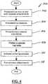
- logic flow diagram 300 of the method for operating a SLS systemis illustrated.
- Logicstarts in operation block 302 where the size of the tool needed is predetermined and attachments required to generate that size of tool are also predetermined.
- the toolis manufactured in a plurality of parts that are joined together through predetermined connectors that are sintered into the sections within the parts cylinder 102.
- the featuressuch as thickness variations 158, gussets 160, stiffeners 162, interfaces and coordination features 164, construction ball interface and coordination holes 170, trim of pockets and drill inserts 166 and holes 168 provided in details for interface hardware, such as screws, are all predetermined for the tool.
- optimal orientation of the SLS tool design within the parts cylinderis predetermined.
- this predeterminationinvolves including all features of the tool 150 on the same side of the tool, thereby limiting warping on tool features in accordance with the present invention.
- heat sinkssuch as 202, 204, or 206
- Alternate embodimentsinclude activating the heat sinks 202, 204, 206 or alternately inputting them into the parts cylinder 102 prior to sintering.
- Further alternate embodimentsinclude a single heat sink, or a heat sink activating in various regions corresponding to tool features on the tool being sintered.
- the sintering processis activated, and the controller 105 activates the pistons 114, 117, the roller 118, the laser 120, and the mirrors 124.
- the pistonsforce sinter material upwards or in a direction of the powder leveling roller 118, which rolls the sinter powder such that it is evenly distributed as a top layer on the parts cylinder 102.
- the laser 120is activated and a beam 126 is directed towards scanning gears, which may be controlled as a function of predetermined requirements made in operation block 302.
- the heat sinks 202, 204, 206are activated for cooling various sintered portions of the tool 150 as they are sintered, and as other parts of the tool are being sintered such that warping is minimized.
- heat sinksmay be included to cool various features of the second tool section as well.
- post-sintering process adjustmentsare conducted. These adjustments include removing warped portions that were deliberately warped such that tool features would not undergo typical warping associated with the sintering process. Further, post-process adjustments involve fitting together components or sections of the tool 150.
- a method for laser sintering a toolincludes predetermining a position for a first tool feature on a first section of the tool; predetermining an orientation of the first section of the tool within the part chamber as a function of minimizing warping of the first tool feature during sintering; activating a heat sink within a part chamber for limiting warping of the first tool feature; laser sintering the first section of the tool within the part chamber; predetermining a position for a second tool feature on a second section of the tool; predetermining an orientation of the second section of the tool within the part chamber as a function of minimizing warping of the second tool feature during sintering; laser sintering the second section of the tool; and coupling the second section to the first section.
Landscapes
- Physics & Mathematics (AREA)
- Optics & Photonics (AREA)
- Chemical & Material Sciences (AREA)
- Engineering & Computer Science (AREA)
- Materials Engineering (AREA)
- Manufacturing & Machinery (AREA)
- Mechanical Engineering (AREA)
- Powder Metallurgy (AREA)
Description
- The present invention relates generally to tooling systems and processes and is more specifically related to the fabrication of tools through selective laser sintering.
- Traditional fabrication methods for tools having areas of contour have included fiberglass lay-ups on numerically controlled machined master models or facility details.
- A manufacturing master model tool, or "master model", is a three-dimensional representation of a part or assembly. The master model controls physical features and shapes during the manufacture or "build" of assembly tools, thereby ensuring that parts and assemblies created using the master model fit together.
- Traditional tool fabrication methods rely on a physical master model. These master models may be made from many different materials including: steel, aluminum, plaster, clay, and composites; and the selection of a specific material has been application dependent. Master models are usually hand-made and require skilled craftsmen to accurately capture the design intent. Once the master model exists, it may be used to duplicate tools.
- The master model becomes the master definition for the contours and edges of a part pattern that the master model represents. The engineering and tool model definitions of those features become reference only.
- Root cause analysis of issues within tool families associated with the master has required tool removal from production for tool fabrication coordination with the master. Tools must also be removed from production for master model coordination when repairing or replacing tool details. Further, the master must be stored and maintained for the life of the tool.
- Master models are costly in that they require design, modeling and surfacing, programming, machine time, hand work, secondary fabrication operations, and inspection prior to use in tool fabrication.
- In summary, although used for years, physical master models have inherent inefficiencies, including: they are costly and difficult to create, use, and maintain; there is a constant risk of damage or loss of the master model; and large master models are difficult and costly to store.
- By way of further background, the field of rapid prototyping of parts has, in recent years, made significant improvements in providing high strength, high density parts for use in the design and pilot production of many useful objects. "Rapid prototyping" generally refers to the manufacture of objects directly from computer-aided-design (CAD) databases in an automated fashion, rather than from conventional machining of prototype objects following engineering drawings. As a result, time required to produce prototype parts from engineering designs has been reduced from several weeks to a matter of a few hours.
- An example of a rapid prototyping technology is the selective laser sintering process (SLS) in which objects are fabricated from a laser-fusible powder. According to this process, a thin layer of powder is dispensed and then fused, melted, or sintered, by a laser beam directed to those portions of the powder corresponding to a cross-section of the object.
- Conventional selective laser sintering systems position the laser beam by way of galvanometer-driven mirrors that deflect the laser beam. The deflection of the laser beam is controlled, in combination with modulation of the laser itself, for directing laser energy to those locations of the fusible powder layer corresponding to the cross-section of the object to be formed in that layer. The laser may be scanned across the powder in a raster fashion or a vector fashion.
- In a number of applications, cross-sections of objects are formed in a powder layer by fusing powder along the outline of the cross-section in vector fashion either before or after a raster scan that fills the area within the vector-drawn outline. After the selective fusing of powder in a given layer, an additional layer of powder is then dispensed and the process repeated, with fused portions of later layers fusing to fused portions of previous layers (as appropriate for the object), until the object is completed.
- Selective laser sintering has enabled the direct manufacture of three-dimensional objects of high resolution and dimensional accuracy from a variety of materials including polystyrene, NYLON, other plastics, and composite materials, such as polymer coated metals and ceramics. In addition, selective laser sintering may be used for the direct fabrication of molds from a CAD database representation of the object in the fabricated molds. Selective Laser Sintering has, however, not been generally available for tool manufacture because of SLS part size limitations, lack if robustness of SLS objects, and inherent limitations in the SLS process.
DE 10051893 discloses components designed in a CAD system that are split into individual modules (7,8,9) which are then manufactured by first forming a base body (7a,8a,9a) which is placed in a laser sintering apparatus. A body (7b,8b,9b) is formed successively on the base body from a powder material by laser sintering, the body representing the difference between the base body and the final module. The resulting modules are assembled into a component. - The disadvantages associated with current tool manufacturing systems have made it apparent that a new and improved tooling system is needed. The new tooling system should reduce need for master models and should reduce time requirements and costs associated with tool manufacture. The new system should also apply SLS technology to tooling applications. The present invention is directed to these ends.
- In accordance with one example, a system for manufacturing a tool within a laser sintering system includes a chamber enclosing a sinter material. The laser sintering system grows or sinters the tool from the sinter material in response to signals from a controller, which generates the signals as a function of a predetermined tool design. A heat sink is positioned within the chamber to cool features of the tool thereby limiting warping of these features during sintering of the tool.
- In an aspect of the invention there is provided a method for laser sintering a tool as claimed in claim 1.
- In accordance with another example, a method for laser sintering a tool includes predetermining a position for a tool feature on a tool section. The method further includes predetermining an orientation of the tool section within a part chamber as a function of minimizing warping of the tool feature during sintering. The tool section is then sintered within the part chamber.
- One advantage of the present invention is that use of Selective Laser Sintering can significantly reduce costs and cycle time associated with the tool fabrication process. An additional advantage is that tool features can be "grown" as represented by the three-dimensional computer model, thus eliminating the requirement for a master model or facility detail. The subsequent maintenance or storage of the master/facility is thereby also eliminated.
- Still another advantage of the present invention is that the model remains the master definition of the tool, therefore root cause analysis or detail replacement may be done directly from the model definition. Secondary fabrication operations are further eliminated where features are "grown" per the three-dimensional solid model definition.
- Additional advantages and features of the present invention will become apparent from the description that follows, and may be realized by means of the instrumentalities and combinations particularly pointed out in the appended claims, taken in conjunction with the accompanying drawings.
- In order that the invention may be well understood, there will now be described some embodiments thereof, given by way of example, reference being made to the accompanying drawings, in which:
FIGURE 1 illustrates an example sintering system:FIGURE 2 illustrates a perspective view of a tool, fabricated in the system ofFIGURE 1 ;FIGURE 3 illustrates an enlarged partial view ofFIGURE 2 ; andFIGURE 4 illustrates a logic flow diagram of a method for operating a sintering system in accordance with an embodiment of the present invention.- The present invention is illustrated with respect to a sintering system particularly suited to the aerospace field. The present invention is, however, applicable to various other uses that may require tooling or parts manufacture, as will be understood by one skilled in the art.
FIGURE 1 illustrates a selectivelaser sintering system 100 having a chamber 102 (the front doors and top ofchamber 102 not shown inFIGURE 1 , for purposes of clarity). Thechamber 102 maintains the appropriate temperature and atmospheric composition (typically an inert atmosphere such as nitrogen) for the fabrication of atool section 104. Thesystem 100 typically operates in response to signals from acontroller 105 controlling, for example,motors pistons laser 120, and mirrors 124, all of which are discussed below. Thecontroller 105 is typically controlled by acomputer 125 or processor running; for example, a computer-aided design program (CAD) defining a cross-section of thetool section 102.- The
system 100 is further adjusted and controlled through various control features, such as the addition of heat sinks, optimal objection orientations, and feature placements, which are detailed herein. - The
chamber 102 encloses a powder sinter material that is delivered therein through a powder delivery system. The powder delivery system insystem 100 includesfeed piston 114, controlled bymotor 106, moving upwardly and lifting a volume of powder into thechamber 102. Two powder feed andcollection pistons 114 may be provided on either side ofpart piston 107, for purposes of efficient and flexible powder delivery.Part piston 107 is controlled bymotor 108 for moving downwardly below the floor of chamber 102 (part cylinder or part chamber) by small amounts, for example 0.125 mm, thereby defining the thickness of each layer of powder undergoing processing. - The roller 118 is a counter-rotating roller that translates powder from
feed piston 114 to targetsurface 115.Target surface 115, for purposes of the description herein, refers to the top surface of heat-fusible powder (including portions previously sintered, if present) disposed abovepart piston 107; the sintered and unsintered powder disposed onpart piston 107 and enclosed by thechamber 102 will be referred to herein as thepart bed 117. Another known powder delivery system feeds powder from abovepart piston 107, in front of a delivery apparatus such as a roller or scraper. - In the selective
laser sintering system 100 ofFIGURE 1 , a laser beam is generated by thelaser 120, and aimed attarget surface 115 by way of ascanning system 122, generally including galvanometer-driven mirrors 124 deflecting thelaser beam 126. The deflection of thelaser beam 126 is controlled, in combination with modulation oflaser 120, for directing laser energy to those locations of the fusible powder layer corresponding to the cross-section of thetool section 104 formed in that layer. Thescanning system 122 may scan the laser beam across the powder in a raster-scan or vector-scan fashion. Alternately, cross-sections oftool sections 104 are also formed in a powder layer by scanning thelaser beam 126 in a vector fashion along the outline of the cross-section in combination with a raster scan that "fills" the area within the vector-drawn outline. - Referring to
FIGURES 1 ,2, and 3 , asample tool 150 formed through theSLS system 100 is illustrated. Thetool 150 includes a plurality of large sections (first 152, second 154, and third 156) or alternately one large section. The sections 152 (alternate example of 104 inFIGURE 1 ), 154, 156 may be sintered simultaneously or consecutively. - During the sintering process, various features are molded into the large tool section or sections. Such features include steps and
thickness variations 158,gussets 160,stiffeners 162, interfaces and coordination features for makinginterfaces 164, construction ball interfaces andcoordination holes 170, trim of pocket and drill inserts 166,hole patterns 172, and holes 168 included in multiple details for interfacing hardware, such asdetail 180. Important to note is that a first plurality of features, including a combination of the aforementioned features, may be sintered into thefirst section 152 and a second plurality of features, including a combination of the aforementioned features, may be sintered into thesecond section 154. - Individually contoured details, such as
detail 180, which may also be considered sections of the tool for the purposes of the present invention, may be sintered separately from the main body of thetool 150, such that they may be easily replaced or replaceable or easily redesigned and incorporated in thetool 150. Alternate embodiments include a plurality of individual contoured details, such as 180, 182, 184, 186. Each of the contoured details includes holes, e.g. 168, such that abolt 190 may bolt thedetail 180 to asection tool 150. - The features, such as the
gusset 160 and thestiffener 162 are, in one embodiment of the present invention, grown on the same side of theSLS tool 150. Growing (i.e. sintering) these features on the same side of the tool takes advantage of the sintering process because a feature grown at the beginning of a sintering operation has different properties than the same feature would when grown at the end of a sintering operation. Therefore, thefirst side 200 undergoing sintering includes all the tool features. - Alternate embodiments of the present invention include various tool features grown on either side of the
tool 150 through various other methods developed in accordance with the present invention. One such method includes adding aheat sink 202, or a plurality ofheat sinks bed 117 such that different tool features may be cooled subsequent to sintering on thefirst section 152 orsecond section 154, thereby avoiding warping that is otherwise inherent in the sintering process. Alternately, a single large heat sink may be placed on one side such that all features cool at the same rate and immediately following the sintering operation. - A further aspect of the present invention includes separating contoured details and various tool aspects by a proximate amount such that warping between the features is limited and structural integrity of the features is maximized.
- An alternate embodiment of the present invention includes designing in access features or buffer features 179 in areas where warping will occur during sintering such that these features may be removed when the sintering process is concluded. These buffer features 179 may be predetermined such that connection between them and the main body of the part facilitates detachment through a twisting off or breaking off procedure for the
buffer feature 179. - Referring to
FIGURE 4 , logic flow diagram 300 of the method for operating a SLS system is illustrated. Logic starts inoperation block 302 where the size of the tool needed is predetermined and attachments required to generate that size of tool are also predetermined. In other words, if the tool requires several sections due to the limitations of thepart cylinder 102, the tool is manufactured in a plurality of parts that are joined together through predetermined connectors that are sintered into the sections within theparts cylinder 102. - In
operation block 304, the features, such asthickness variations 158,gussets 160,stiffeners 162, interfaces and coordination features 164, construction ball interface andcoordination holes 170, trim of pockets and drill inserts 166 and holes 168 provided in details for interface hardware, such as screws, are all predetermined for the tool. - In
operation block 306, optimal orientation of the SLS tool design within the parts cylinder is predetermined. In one embodiment of the present invention, this predetermination involves including all features of thetool 150 on the same side of the tool, thereby limiting warping on tool features in accordance with the present invention. - In
operation block 308 heat sinks, such as 202, 204, or 206, are positioned in various parts of theparts cylinder 102 such that tool features may be cooled immediately following the sintering process and while the rest of the tool or tool components are being sintered, thereby minimizing warping of the tool features. Alternate embodiments include activating theheat sinks parts cylinder 102 prior to sintering. Further alternate embodiments include a single heat sink, or a heat sink activating in various regions corresponding to tool features on the tool being sintered. - In
operation block 310 the sintering process is activated, and thecontroller 105 activates thepistons laser 120, and the mirrors 124. The pistons force sinter material upwards or in a direction of the powder leveling roller 118, which rolls the sinter powder such that it is evenly distributed as a top layer on theparts cylinder 102. Thelaser 120 is activated and abeam 126 is directed towards scanning gears, which may be controlled as a function of predetermined requirements made inoperation block 302. During the sintering operations, theheat sinks tool 150 as they are sintered, and as other parts of the tool are being sintered such that warping is minimized. In alternate embodiments wherein a plurality of tool sections, such as a first and second tool section, are sintered collectively or successively, heat sinks may be included to cool various features of the second tool section as well. - In
operation block 312, post-sintering process adjustments are conducted. These adjustments include removing warped portions that were deliberately warped such that tool features would not undergo typical warping associated with the sintering process. Further, post-process adjustments involve fitting together components or sections of thetool 150. - In operation, a method for laser sintering a tool includes predetermining a position for a first tool feature on a first section of the tool; predetermining an orientation of the first section of the tool within the part chamber as a function of minimizing warping of the first tool feature during sintering; activating a heat sink within a part chamber for limiting warping of the first tool feature; laser sintering the first section of the tool within the part chamber; predetermining a position for a second tool feature on a second section of the tool; predetermining an orientation of the second section of the tool within the part chamber as a function of minimizing warping of the second tool feature during sintering; laser sintering the second section of the tool; and coupling the second section to the first section.
Claims (11)
- A method for laser sintering a tool comprising:predetermining a position for a first tool feature on a first section of the tool;predetermining an orientation of said first section of the tool within the part chamber (102) as a function of minimizing warping of said first tool feature during sintering;activating a heat sink (202, 204, 206) within a part chamber for limiting warping of said first tool feature;laser sintering said first section of the tool within said part chamber;predetermining a position for a second tool feature on a second section of the tool;predetermining an orientation of said second section of the tool within said part chamber as a function of minimizing warping of said second tool feature during sintering;laser sintering said second section of the tool; andcoupling said second section to said first section;the method further comprising:predetermining a location of a buffer feature (179) in a close proximity to said first tool feature, the buffer feature positioned to undergo warping during sintering such that said first tool feature does not undergo warping during sintering; andremoving said buffer feature (179) from the tool following sintering of the tool.
- The method of claim 1 further comprising predetermining positions of a plurality of tool features on said first section of the tool.
- The method of claim 2, wherein predetermining said orientation of the tool within the part chamber (102) as a function of minimizing warping said tool features further comprises orienting the tool such that all of said tool features are on a same side of the tool.
- The method of claim 1 further comprising predetermining positions of a plurality of tool features on said second section of the tool.
- The method of claim 1 further comprising activating a plurality of heat sinks (202, 204, 206) at predetermined times within said part chamber for limiting warping of a plurality of predetermined tool features on either said first section or said second section.
- The method of claim 1, wherein predetermining positions of said first tool feature further comprise predetermining a position for at least one of a step and thickness variation (158), a gusset (160), a stiffener (162), an interface and coordination feature for making interfaces (164), a construction ball interface, a coordination hole (170), a trim of pocket and drill insert (166), a hole pattern (172), or a hole for interfacing hardware (168).
- The method of claim 1 further comprising activating a second heat sink within said part chamber (102) for limiting warping of said second tool feature.
- The method of claims 1 or 7 further comprising:cooling said first tool feature during sintering of said first tool section; andcooling said second tool feature during sintering of said second tool section;
- The method of claims 1 or 8 further comprising sintering a separate contour detail (180); and coupling said contour detail to said first section after said first section has been sintered.
- The method of claim 9, wherein coupling said contour detail further comprises coupling said contour detail to said first section with a bolt.
- The method of claim 1 or 8 further comprising sintering a plurality of separate contour details (180); and coupling said plurality of contour details to both said first section and said second section after the first and second sections have been sintered.
Applications Claiming Priority (2)
| Application Number | Priority Date | Filing Date | Title |
|---|---|---|---|
| US10/710,163US20050287031A1 (en) | 2004-06-23 | 2004-06-23 | SLS For Tooling Applications |
| PCT/US2005/021779WO2006007457A2 (en) | 2004-06-23 | 2005-06-21 | Sls for tooling applications |
Publications (2)
| Publication Number | Publication Date |
|---|---|
| EP1773804A2 EP1773804A2 (en) | 2007-04-18 |
| EP1773804B1true EP1773804B1 (en) | 2016-12-07 |
Family
ID=35058185
Family Applications (1)
| Application Number | Title | Priority Date | Filing Date |
|---|---|---|---|
| EP05772019.5AExpired - LifetimeEP1773804B1 (en) | 2004-06-23 | 2005-06-21 | Sls for tooling applications |
Country Status (4)
| Country | Link |
|---|---|
| US (1) | US20050287031A1 (en) |
| EP (1) | EP1773804B1 (en) |
| ES (1) | ES2617085T3 (en) |
| WO (1) | WO2006007457A2 (en) |
Families Citing this family (22)
| Publication number | Priority date | Publication date | Assignee | Title |
|---|---|---|---|---|
| FR2857889B1 (en)* | 2003-07-23 | 2005-09-23 | Snecma Moteurs | PROCESS FOR PRODUCING PARTS BY PRECISION FORGING |
| US7799256B2 (en)* | 2008-08-05 | 2010-09-21 | Toyota Motor Engineering & Manufacturing North America, Inc. | Methods of manufacturing molds and parts |
| US20130255346A1 (en)* | 2012-03-29 | 2013-10-03 | A. Raymond Et Cie | Metal-stamping die manufactured by additive manufacturing |
| US9486878B2 (en) | 2014-06-20 | 2016-11-08 | Velo3D, Inc. | Apparatuses, systems and methods for three-dimensional printing |
| CN104259458B (en)* | 2014-09-29 | 2017-01-18 | 湖南华曙高科技有限责任公司 | Rapid prototyping device for three-dimensional object manufacture and heating device thereof |
| CN104942289A (en)* | 2015-07-14 | 2015-09-30 | 长春工业大学 | Method for performing spark plasma sintering on alloy powder particles by adopting sintering aid |
| US10065270B2 (en) | 2015-11-06 | 2018-09-04 | Velo3D, Inc. | Three-dimensional printing in real time |
| US10286603B2 (en) | 2015-12-10 | 2019-05-14 | Velo3D, Inc. | Skillful three-dimensional printing |
| US20170239719A1 (en) | 2016-02-18 | 2017-08-24 | Velo3D, Inc. | Accurate three-dimensional printing |
| EP3492244A1 (en) | 2016-06-29 | 2019-06-05 | VELO3D, Inc. | Three-dimensional printing system and method for three-dimensional printing |
| US11691343B2 (en) | 2016-06-29 | 2023-07-04 | Velo3D, Inc. | Three-dimensional printing and three-dimensional printers |
| US20180093418A1 (en) | 2016-09-30 | 2018-04-05 | Velo3D, Inc. | Three-dimensional objects and their formation |
| US10744563B2 (en) | 2016-10-17 | 2020-08-18 | The Boeing Company | 3D printing of an object from powdered material using pressure waves |
| US20180126460A1 (en) | 2016-11-07 | 2018-05-10 | Velo3D, Inc. | Gas flow in three-dimensional printing |
| US20180186082A1 (en) | 2017-01-05 | 2018-07-05 | Velo3D, Inc. | Optics in three-dimensional printing |
| US10315252B2 (en) | 2017-03-02 | 2019-06-11 | Velo3D, Inc. | Three-dimensional printing of three-dimensional objects |
| US10449696B2 (en) | 2017-03-28 | 2019-10-22 | Velo3D, Inc. | Material manipulation in three-dimensional printing |
| US10272525B1 (en) | 2017-12-27 | 2019-04-30 | Velo3D, Inc. | Three-dimensional printing systems and methods of their use |
| US10144176B1 (en) | 2018-01-15 | 2018-12-04 | Velo3D, Inc. | Three-dimensional printing systems and methods of their use |
| US11440255B2 (en)* | 2018-09-14 | 2022-09-13 | MRI. Materials Resources LLC | Additive manufacturing under generated force |
| CN113423752A (en) | 2018-12-21 | 2021-09-21 | 亨茨曼国际有限公司 | Crosslinkable thermoplastic powder for powder-based additive manufacturing |
| CA3148849A1 (en) | 2019-07-26 | 2021-02-04 | Velo3D, Inc. | Quality assurance in formation of three-dimensional objects |
Citations (1)
| Publication number | Priority date | Publication date | Assignee | Title |
|---|---|---|---|---|
| US5304329A (en)* | 1992-11-23 | 1994-04-19 | The B. F. Goodrich Company | Method of recovering recyclable unsintered powder from the part bed of a selective laser-sintering machine |
Family Cites Families (8)
| Publication number | Priority date | Publication date | Assignee | Title |
|---|---|---|---|---|
| US5155324A (en)* | 1986-10-17 | 1992-10-13 | Deckard Carl R | Method for selective laser sintering with layerwise cross-scanning |
| US5216616A (en)* | 1989-06-26 | 1993-06-01 | Masters William E | System and method for computer automated manufacture with reduced object shape distortion |
| WO1992008592A1 (en)* | 1990-11-09 | 1992-05-29 | Dtm Corporation | Controlled gas flow for selective laser sintering |
| US5155321A (en)* | 1990-11-09 | 1992-10-13 | Dtm Corporation | Radiant heating apparatus for providing uniform surface temperature useful in selective laser sintering |
| US5648450A (en)* | 1992-11-23 | 1997-07-15 | Dtm Corporation | Sinterable semi-crystalline powder and near-fully dense article formed therein |
| US5352405A (en)* | 1992-12-18 | 1994-10-04 | Dtm Corporation | Thermal control of selective laser sintering via control of the laser scan |
| WO2001028733A1 (en)* | 1999-10-19 | 2001-04-26 | Fraunhofer Gesellschaft Zur Förderung Der Angewandt En Forschung E.V. | Method for producing metallic components, especially tool inserts |
| US7195429B2 (en)* | 2003-10-20 | 2007-03-27 | The Boeing Company | Drill template with integral vacuum attach |
- 2004
- 2004-06-23USUS10/710,163patent/US20050287031A1/ennot_activeAbandoned
- 2005
- 2005-06-21ESES05772019.5Tpatent/ES2617085T3/ennot_activeExpired - Lifetime
- 2005-06-21WOPCT/US2005/021779patent/WO2006007457A2/ennot_activeApplication Discontinuation
- 2005-06-21EPEP05772019.5Apatent/EP1773804B1/ennot_activeExpired - Lifetime
Patent Citations (1)
| Publication number | Priority date | Publication date | Assignee | Title |
|---|---|---|---|---|
| US5304329A (en)* | 1992-11-23 | 1994-04-19 | The B. F. Goodrich Company | Method of recovering recyclable unsintered powder from the part bed of a selective laser-sintering machine |
Also Published As
| Publication number | Publication date |
|---|---|
| WO2006007457A3 (en) | 2006-08-31 |
| ES2617085T3 (en) | 2017-06-15 |
| WO2006007457A2 (en) | 2006-01-19 |
| US20050287031A1 (en) | 2005-12-29 |
| EP1773804A2 (en) | 2007-04-18 |
Similar Documents
| Publication | Publication Date | Title |
|---|---|---|
| EP1773804B1 (en) | Sls for tooling applications | |
| US20050278933A1 (en) | Joint Design For Large SLS Details | |
| Akula et al. | Hybrid adaptive layer manufacturing: An Intelligent art of direct metal rapid tooling process | |
| US10532513B2 (en) | Method and arrangement for producing a workpiece by using additive manufacturing techniques | |
| US5398193A (en) | Method of three-dimensional rapid prototyping through controlled layerwise deposition/extraction and apparatus therefor | |
| Manogharan et al. | AIMS–a metal additive-hybrid manufacturing system: system architecture and attributes | |
| Altan et al. | Advanced techniques for die and mold manufacturing | |
| Kai | Three-dimensional rapid prototyping technologies and key development areas | |
| Zhu et al. | Application of a hybrid process for high precision manufacture of difficult to machine prismatic parts | |
| CN106694872A (en) | Compound additional material manufacturing method applicable to parts and dies | |
| Hartmann et al. | Robot-assisted shape deposition manufacturing | |
| Kerschbaumer et al. | Hybrid manufacturing process for rapid high performance tooling combining high speed milling and laser cladding | |
| US11884025B2 (en) | Three-dimensional printer and methods for assembling parts via integration of additive and conventional manufacturing operations | |
| Kumar | Additive manufacturing solutions | |
| Karunakaran et al. | Techno-economic analysis of hybrid layered manufacturing | |
| US20050285314A1 (en) | Integral Nut Slot System In SLS Details | |
| US20050280189A1 (en) | Undercut For Bushing Retention For SLS Details | |
| Karunakaran et al. | Hybrid layered manufacturing: direct rapid metal tool-making process | |
| Yasa et al. | Repair and manufacturing of high performance tools by additive manufacturing | |
| Landers et al. | Reconfigurable manufacturing equipment | |
| Fudali et al. | Comparison of geometric precision of plastic components made by subtractive and additive methods | |
| Dimov et al. | Tool-path generation system for micro-electro discharge machining milling | |
| Ader et al. | Research on layer manufacturing techniques at Fraunhofer | |
| Junk et al. | Additive tooling for thermoforming a cowling of an UAV using binder jetting | |
| Srivastava et al. | Trends in the domain of rapid rototyping: a review |
Legal Events
| Date | Code | Title | Description |
|---|---|---|---|
| PUAI | Public reference made under article 153(3) epc to a published international application that has entered the european phase | Free format text:ORIGINAL CODE: 0009012 | |
| 17P | Request for examination filed | Effective date:20061222 | |
| AK | Designated contracting states | Kind code of ref document:A2 Designated state(s):AT BE BG CH CY CZ DE DK EE ES FI FR GB GR HU IE IS IT LI LT LU MC NL PL PT RO SE SI SK TR | |
| DAX | Request for extension of the european patent (deleted) | ||
| 17Q | First examination report despatched | Effective date:20110426 | |
| GRAP | Despatch of communication of intention to grant a patent | Free format text:ORIGINAL CODE: EPIDOSNIGR1 | |
| INTG | Intention to grant announced | Effective date:20160622 | |
| GRAS | Grant fee paid | Free format text:ORIGINAL CODE: EPIDOSNIGR3 | |
| GRAA | (expected) grant | Free format text:ORIGINAL CODE: 0009210 | |
| AK | Designated contracting states | Kind code of ref document:B1 Designated state(s):AT BE BG CH CY CZ DE DK EE ES FI FR GB GR HU IE IS IT LI LT LU MC NL PL PT RO SE SI SK TR | |
| REG | Reference to a national code | Ref country code:GB Ref legal event code:FG4D | |
| REG | Reference to a national code | Ref country code:CH Ref legal event code:EP Ref country code:AT Ref legal event code:REF Ref document number:851580 Country of ref document:AT Kind code of ref document:T Effective date:20161215 | |
| REG | Reference to a national code | Ref country code:IE Ref legal event code:FG4D | |
| REG | Reference to a national code | Ref country code:DE Ref legal event code:R096 Ref document number:602005050862 Country of ref document:DE | |
| REG | Reference to a national code | Ref country code:LT Ref legal event code:MG4D | |
| REG | Reference to a national code | Ref country code:NL Ref legal event code:MP Effective date:20161207 | |
| PG25 | Lapsed in a contracting state [announced via postgrant information from national office to epo] | Ref country code:SE Free format text:LAPSE BECAUSE OF FAILURE TO SUBMIT A TRANSLATION OF THE DESCRIPTION OR TO PAY THE FEE WITHIN THE PRESCRIBED TIME-LIMIT Effective date:20161207 Ref country code:LT Free format text:LAPSE BECAUSE OF FAILURE TO SUBMIT A TRANSLATION OF THE DESCRIPTION OR TO PAY THE FEE WITHIN THE PRESCRIBED TIME-LIMIT Effective date:20161207 Ref country code:GR Free format text:LAPSE BECAUSE OF FAILURE TO SUBMIT A TRANSLATION OF THE DESCRIPTION OR TO PAY THE FEE WITHIN THE PRESCRIBED TIME-LIMIT Effective date:20170308 | |
| REG | Reference to a national code | Ref country code:AT Ref legal event code:MK05 Ref document number:851580 Country of ref document:AT Kind code of ref document:T Effective date:20161207 | |
| PG25 | Lapsed in a contracting state [announced via postgrant information from national office to epo] | Ref country code:FI Free format text:LAPSE BECAUSE OF FAILURE TO SUBMIT A TRANSLATION OF THE DESCRIPTION OR TO PAY THE FEE WITHIN THE PRESCRIBED TIME-LIMIT Effective date:20161207 | |
| REG | Reference to a national code | Ref country code:ES Ref legal event code:FG2A Ref document number:2617085 Country of ref document:ES Kind code of ref document:T3 Effective date:20170615 | |
| REG | Reference to a national code | Ref country code:FR Ref legal event code:PLFP Year of fee payment:13 | |
| PG25 | Lapsed in a contracting state [announced via postgrant information from national office to epo] | Ref country code:NL Free format text:LAPSE BECAUSE OF FAILURE TO SUBMIT A TRANSLATION OF THE DESCRIPTION OR TO PAY THE FEE WITHIN THE PRESCRIBED TIME-LIMIT Effective date:20161207 | |
| PG25 | Lapsed in a contracting state [announced via postgrant information from national office to epo] | Ref country code:SK Free format text:LAPSE BECAUSE OF FAILURE TO SUBMIT A TRANSLATION OF THE DESCRIPTION OR TO PAY THE FEE WITHIN THE PRESCRIBED TIME-LIMIT Effective date:20161207 Ref country code:RO Free format text:LAPSE BECAUSE OF FAILURE TO SUBMIT A TRANSLATION OF THE DESCRIPTION OR TO PAY THE FEE WITHIN THE PRESCRIBED TIME-LIMIT Effective date:20161207 Ref country code:EE Free format text:LAPSE BECAUSE OF FAILURE TO SUBMIT A TRANSLATION OF THE DESCRIPTION OR TO PAY THE FEE WITHIN THE PRESCRIBED TIME-LIMIT Effective date:20161207 Ref country code:IS Free format text:LAPSE BECAUSE OF FAILURE TO SUBMIT A TRANSLATION OF THE DESCRIPTION OR TO PAY THE FEE WITHIN THE PRESCRIBED TIME-LIMIT Effective date:20170407 Ref country code:CZ Free format text:LAPSE BECAUSE OF FAILURE TO SUBMIT A TRANSLATION OF THE DESCRIPTION OR TO PAY THE FEE WITHIN THE PRESCRIBED TIME-LIMIT Effective date:20161207 | |
| PGFP | Annual fee paid to national office [announced via postgrant information from national office to epo] | Ref country code:GB Payment date:20170627 Year of fee payment:13 Ref country code:FR Payment date:20170627 Year of fee payment:13 | |
| PG25 | Lapsed in a contracting state [announced via postgrant information from national office to epo] | Ref country code:PL Free format text:LAPSE BECAUSE OF FAILURE TO SUBMIT A TRANSLATION OF THE DESCRIPTION OR TO PAY THE FEE WITHIN THE PRESCRIBED TIME-LIMIT Effective date:20161207 Ref country code:PT Free format text:LAPSE BECAUSE OF FAILURE TO SUBMIT A TRANSLATION OF THE DESCRIPTION OR TO PAY THE FEE WITHIN THE PRESCRIBED TIME-LIMIT Effective date:20170407 Ref country code:BG Free format text:LAPSE BECAUSE OF FAILURE TO SUBMIT A TRANSLATION OF THE DESCRIPTION OR TO PAY THE FEE WITHIN THE PRESCRIBED TIME-LIMIT Effective date:20170307 Ref country code:AT Free format text:LAPSE BECAUSE OF FAILURE TO SUBMIT A TRANSLATION OF THE DESCRIPTION OR TO PAY THE FEE WITHIN THE PRESCRIBED TIME-LIMIT Effective date:20161207 Ref country code:BE Free format text:LAPSE BECAUSE OF FAILURE TO SUBMIT A TRANSLATION OF THE DESCRIPTION OR TO PAY THE FEE WITHIN THE PRESCRIBED TIME-LIMIT Effective date:20161207 | |
| PGFP | Annual fee paid to national office [announced via postgrant information from national office to epo] | Ref country code:IT Payment date:20170622 Year of fee payment:13 | |
| REG | Reference to a national code | Ref country code:DE Ref legal event code:R097 Ref document number:602005050862 Country of ref document:DE | |
| PLBE | No opposition filed within time limit | Free format text:ORIGINAL CODE: 0009261 | |
| STAA | Information on the status of an ep patent application or granted ep patent | Free format text:STATUS: NO OPPOSITION FILED WITHIN TIME LIMIT | |
| PGFP | Annual fee paid to national office [announced via postgrant information from national office to epo] | Ref country code:DE Payment date:20170628 Year of fee payment:13 Ref country code:ES Payment date:20170705 Year of fee payment:13 | |
| 26N | No opposition filed | Effective date:20170908 | |
| PG25 | Lapsed in a contracting state [announced via postgrant information from national office to epo] | Ref country code:SI Free format text:LAPSE BECAUSE OF FAILURE TO SUBMIT A TRANSLATION OF THE DESCRIPTION OR TO PAY THE FEE WITHIN THE PRESCRIBED TIME-LIMIT Effective date:20161207 Ref country code:DK Free format text:LAPSE BECAUSE OF FAILURE TO SUBMIT A TRANSLATION OF THE DESCRIPTION OR TO PAY THE FEE WITHIN THE PRESCRIBED TIME-LIMIT Effective date:20161207 | |
| PG25 | Lapsed in a contracting state [announced via postgrant information from national office to epo] | Ref country code:MC Free format text:LAPSE BECAUSE OF FAILURE TO SUBMIT A TRANSLATION OF THE DESCRIPTION OR TO PAY THE FEE WITHIN THE PRESCRIBED TIME-LIMIT Effective date:20161207 | |
| REG | Reference to a national code | Ref country code:CH Ref legal event code:PL | |
| REG | Reference to a national code | Ref country code:IE Ref legal event code:MM4A | |
| PG25 | Lapsed in a contracting state [announced via postgrant information from national office to epo] | Ref country code:LU Free format text:LAPSE BECAUSE OF NON-PAYMENT OF DUE FEES Effective date:20170621 Ref country code:LI Free format text:LAPSE BECAUSE OF NON-PAYMENT OF DUE FEES Effective date:20170630 Ref country code:CH Free format text:LAPSE BECAUSE OF NON-PAYMENT OF DUE FEES Effective date:20170630 Ref country code:IE Free format text:LAPSE BECAUSE OF NON-PAYMENT OF DUE FEES Effective date:20170621 | |
| REG | Reference to a national code | Ref country code:DE Ref legal event code:R119 Ref document number:602005050862 Country of ref document:DE | |
| GBPC | Gb: european patent ceased through non-payment of renewal fee | Effective date:20180621 | |
| PG25 | Lapsed in a contracting state [announced via postgrant information from national office to epo] | Ref country code:IT Free format text:LAPSE BECAUSE OF NON-PAYMENT OF DUE FEES Effective date:20180621 Ref country code:FR Free format text:LAPSE BECAUSE OF NON-PAYMENT OF DUE FEES Effective date:20180630 Ref country code:GB Free format text:LAPSE BECAUSE OF NON-PAYMENT OF DUE FEES Effective date:20180621 Ref country code:DE Free format text:LAPSE BECAUSE OF NON-PAYMENT OF DUE FEES Effective date:20190101 | |
| PG25 | Lapsed in a contracting state [announced via postgrant information from national office to epo] | Ref country code:HU Free format text:LAPSE BECAUSE OF FAILURE TO SUBMIT A TRANSLATION OF THE DESCRIPTION OR TO PAY THE FEE WITHIN THE PRESCRIBED TIME-LIMIT; INVALID AB INITIO Effective date:20050621 | |
| REG | Reference to a national code | Ref country code:ES Ref legal event code:FD2A Effective date:20190916 | |
| PG25 | Lapsed in a contracting state [announced via postgrant information from national office to epo] | Ref country code:ES Free format text:LAPSE BECAUSE OF NON-PAYMENT OF DUE FEES Effective date:20180622 Ref country code:CY Free format text:LAPSE BECAUSE OF NON-PAYMENT OF DUE FEES Effective date:20161207 | |
| PG25 | Lapsed in a contracting state [announced via postgrant information from national office to epo] | Ref country code:TR Free format text:LAPSE BECAUSE OF FAILURE TO SUBMIT A TRANSLATION OF THE DESCRIPTION OR TO PAY THE FEE WITHIN THE PRESCRIBED TIME-LIMIT Effective date:20161207 |