EP1773507B1 - Color change for powder coating material application system - Google Patents
Color change for powder coating material application systemDownload PDFInfo
- Publication number
- EP1773507B1 EP1773507B1EP05759593AEP05759593AEP1773507B1EP 1773507 B1EP1773507 B1EP 1773507B1EP 05759593 AEP05759593 AEP 05759593AEP 05759593 AEP05759593 AEP 05759593AEP 1773507 B1EP1773507 B1EP 1773507B1
- Authority
- EP
- European Patent Office
- Prior art keywords
- pump
- purge
- inlet
- powder coating
- coating material
- Prior art date
- Legal status (The legal status is an assumption and is not a legal conclusion. Google has not performed a legal analysis and makes no representation as to the accuracy of the status listed.)
- Expired - Lifetime
Links
Images


Classifications
- B—PERFORMING OPERATIONS; TRANSPORTING
- B05—SPRAYING OR ATOMISING IN GENERAL; APPLYING FLUENT MATERIALS TO SURFACES, IN GENERAL
- B05B—SPRAYING APPARATUS; ATOMISING APPARATUS; NOZZLES
- B05B15/00—Details of spraying plant or spraying apparatus not otherwise provided for; Accessories
- B05B15/50—Arrangements for cleaning; Arrangements for preventing deposits, drying-out or blockage; Arrangements for detecting improper discharge caused by the presence of foreign matter
- B05B15/52—Arrangements for cleaning; Arrangements for preventing deposits, drying-out or blockage; Arrangements for detecting improper discharge caused by the presence of foreign matter for removal of clogging particles
- B—PERFORMING OPERATIONS; TRANSPORTING
- B05—SPRAYING OR ATOMISING IN GENERAL; APPLYING FLUENT MATERIALS TO SURFACES, IN GENERAL
- B05B—SPRAYING APPARATUS; ATOMISING APPARATUS; NOZZLES
- B05B7/00—Spraying apparatus for discharge of liquids or other fluent materials from two or more sources, e.g. of liquid and air, of powder and gas
- B05B7/14—Spraying apparatus for discharge of liquids or other fluent materials from two or more sources, e.g. of liquid and air, of powder and gas designed for spraying particulate materials
- B05B7/1404—Arrangements for supplying particulate material
- B05B7/1459—Arrangements for supplying particulate material comprising a chamber, inlet and outlet valves upstream and downstream the chamber and means for alternately sucking particulate material into and removing particulate material from the chamber through the valves
- B—PERFORMING OPERATIONS; TRANSPORTING
- B05—SPRAYING OR ATOMISING IN GENERAL; APPLYING FLUENT MATERIALS TO SURFACES, IN GENERAL
- B05B—SPRAYING APPARATUS; ATOMISING APPARATUS; NOZZLES
- B05B12/00—Arrangements for controlling delivery; Arrangements for controlling the spray area
- B05B12/14—Arrangements for controlling delivery; Arrangements for controlling the spray area for supplying a selected one of a plurality of liquids or other fluent materials or several in selected proportions to a spray apparatus, e.g. to a single spray outlet
- B05B12/149—Arrangements for controlling delivery; Arrangements for controlling the spray area for supplying a selected one of a plurality of liquids or other fluent materials or several in selected proportions to a spray apparatus, e.g. to a single spray outlet characterised by colour change manifolds or valves therefor
- B—PERFORMING OPERATIONS; TRANSPORTING
- B05—SPRAYING OR ATOMISING IN GENERAL; APPLYING FLUENT MATERIALS TO SURFACES, IN GENERAL
- B05B—SPRAYING APPARATUS; ATOMISING APPARATUS; NOZZLES
- B05B7/00—Spraying apparatus for discharge of liquids or other fluent materials from two or more sources, e.g. of liquid and air, of powder and gas
- B05B7/14—Spraying apparatus for discharge of liquids or other fluent materials from two or more sources, e.g. of liquid and air, of powder and gas designed for spraying particulate materials
- B05B7/1404—Arrangements for supplying particulate material
- B—PERFORMING OPERATIONS; TRANSPORTING
- B05—SPRAYING OR ATOMISING IN GENERAL; APPLYING FLUENT MATERIALS TO SURFACES, IN GENERAL
- B05B—SPRAYING APPARATUS; ATOMISING APPARATUS; NOZZLES
- B05B14/00—Arrangements for collecting, re-using or eliminating excess spraying material
- B05B14/40—Arrangements for collecting, re-using or eliminating excess spraying material for use in spray booths
- B05B14/48—Arrangements for collecting, re-using or eliminating excess spraying material for use in spray booths specially adapted for particulate material
Definitions
- the inventionrelates generally to material application systems, such as for example powder coating material application systems, and more particularly to apparatus and methods for improved material change operations such as for example quick color change.
- a typical powder coating material application systemincludes one or more sources or supplies of powder coating material, a pump arrangement and a spray applicator such as a spray gun.
- a spray applicatorsuch as a spray gun.
- the powder coating materialsare sprayed within a spray booth that contains powder overspray and also has an overspray recovery system to collect powder overspray and either reclaim it for further use or disposal.
- Spray gunsare typically either manual guns that are hand held during operation, or automatic guns that are mounted on a support and are triggered and controlled by an electronic control system.
- the spray gunsmay be electrostatic such as corona or tribo-charging, or non-electrostatic.
- a supply hoseis commonly used to connect a powder source such as a hopper to a pump inlet, and a feed hose is commonly used to connect a pump outlet to a spray gun inlet or multiple gun inlets.
- These hosesare typically flexible plastic hoses.
- powder coating material application systemsare designed to apply a wide variety of powder coating materials to an even wider variety of objects.
- Different powder coating materialsusually involve different colors, but may further include different types of material such as polymeric, such as for example epoxies, polyesters and hybrids of epoxies and polyesters, or metallic, for example polyester with aluminum flaks.
- the application systemIn order to change over from spraying one type or colour powder coating material to another, the application system must be thoroughly cleaned of the previous material before the next material is sprayed, in order to prevent contaminating the new spraying operation. This involves not only cleaning exterior surfaces such as the spray booth and spray guns, but also the entire powder flow path from the supply to the pump and through the outlet of all of the spray guns that were used in the previous spraying operation. These colour change or material change operations are time and labour intensive and therefore are a significant cost factor.
- US 2002/0166899 A1discloses a manifold block for controlling the flow of liquids and useful in the application of paint to automotive vehicles and in other, similar, applications is provided.
- the manifold blockhouses at least one liquid inlet supply channel, at least one liquid return channel, and an applicator channel in microvalved connection with the inlet channel and the outlet channel, which channels meet at a common intersection in adjacent proximity of the microvalve.
- EP 1270087 A1discloses a powder coating material system according to the preamble of claim 1, comprising an applicator, a first powder coating material supply and a second powder coating material supply, a pump having a pump inlet to transport powder material from a selected one of said first and second powder coating material supplies and a pump outlet to supply powder coating material to said applicator, a powder coating material changer having a first inlet connected to said first powder coating material supply, and a second inlet connected to said second powder coating material supply.
- the present inventionprovides a powder coating material system which is characterized in that said powder coating material changer has a common feed passage selectively in flow communication with each of said first and second inlets, said common feed passage has a changer outlet connected to said pump inlet of said pump, each inlet connecting to said common feed passage through a respective port formed in a wall of said common feed passage, a first valve associated with said first inlet and a second valve associated with said second inlet, each valve operable to prevent flow between its associated inlet and said common feed passage by blocking said port; in that said pump comprises a cylindrical pump chamber, said pump chamber alternately being put under negative and positive pressure; in that said pump has a supply mode wherein when said pump chamber is put under negative pressure, air and powder coating material are sucked through said pump inlet into said pump chamber from said selected one of said powder coating material supplies through said powder coating material changer common feed passage in a first direction, and when said pump chamber is put under positive pressure, air and powder coating material are pushed out of said pump chamber through said pump outlet to said applicator, and in
- the powder coating material application systemhas a material changer function that, at least in preferred embodiments, is fast and efficient, such as, for example, for a colour change operation.
- the changer functionallows for material flow in one direction and a purge flow in an opposite direction.
- the material changerhas a common feed passage connected to a plurality of material supplies, with each supply having an associated inlet passage that opens to the common passage at a port that is sealed by a valve member.
- the portis formed in the wall that defines the common feed passage.
- the valve memberseals the port with a near bore line seal.
- the valve memberis inflatable by air pressure and a portion of the valve member slightly protrudes into the common feed passage, in effect creating a "zero cavity" or near bore line seal.
- the common feed passagecan be reverse purged with all of the inlet valves closed to an outlet that may be connected to a waste receptacle or other powder collector such as the spray booth.
- the pumpproduces a soft purge function and a hard purge function
- the changermay be purged to a waste or dump outlet and also through the last inlet used during a coating operation.
- the changerin one embodiment includes control valves that form near bore line seals with a common feed passage, and a reverse purge flow feature.
- the reverse purge featuremay be realized in the form of a reverse flow purge through the common feed passage to all outlet, and optionally through the previous used inlet.
- An optional purge feature in the forward directionmay also be provided.
- the changer, or at least the material flow path within the changeris made from low impact fusion material, for example, PTFE (TEFLON TM ) or high density polyethylene.
- each control valveincludes a valve member such as a bladder that is made of elastic material, such as for example natural rubber, and expands under air pressure to seal a port that joins an inlet to a common feed passage.
- the pumpmay be a dense phase pump.
- control of powder flow through a changeris realized by the application of positive pressure to a valve function to cause a valve member to expand and close a port.
- Fig. 1is a schematic diagram of a supply for a powder coating material application system using a material changer and a pump;
- Fig. 1Ais a plan or top view of an alternative configuration for a color changer in accordance with the invention.
- Fig. 2is a detailed schematic of two gun powder coating material application system using the present invention
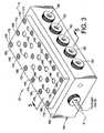
- Fig. 3is a material changer in isometric
- Fig. 4is the material changer of Fig. 3 in exploded perspective
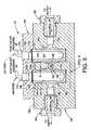
- Fig. 5is a cross-section of the changer of Fig. 3 taken along the line 5-5 in Fig. 3 showing inlet valves in an open position;
- Fig. 6is an enlarged view of the circled region in Fig. 5 but showing an inlet valve in a closed position;
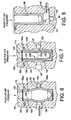
- Fig. 7is a second embodiment of an inlet valve for the changer of Fig. 3 ;
- Fig. 8is a third embodiment of an inlet valve for the changer of Fig. 3 .
- the disclosed material application systemmay be used for the application of powder coating materials such as paint, lacquers and so on.
- a supply 10 for a material application systemis illustrated, and includes a material changer function 12 and a pump function 14.
- the material changer function 12may be used for changing between one supply of material and another supply of material up to N number of supplies.
- the material changermay be used to change colors or types of material.
- Fig. 1also illustrates schematically the relational flows for material and air during a supply mode of operation and during a purge mode of operation.
- supply mode of operationis meant that material is being fed from a selected one of the N supplies to the pump and on to a user function, such as a spray gun for example or another receptacle such as a hopper.
- purge mode of operationis meant that as part of a color change or other material change operation, cleaning operation or maintenance operation, the material flow path needs to be cleaned or purged of the previous material before a newly selected material can be used.
- Fig. 1Immediately apparent from the flow arrows in Fig. 1 is an appreciation that material flows in a first direction and the purge air flows in a second direction that is opposite the first direction, as will be more fully described hereinafter.
- An optional second purge functionis available to purge the changer in the same direction as the material flow direction.
- the pump function 14may be realized for example using a pump 16 having a powder inlet 18 and a powder outlet 20.
- the powder outlet 20may be connected by an application hose such as for example a spray gun hose 22 to another application or use 24, such as for example a spray gun, hopper and so forth.
- the pump I6may be, for example, a dense phase pump or other suitable pump design. Examples of pumps suitable for use with the present invention but not intended to be exclusive, are described in the following publications and applications: United States patent application serial no. 10/501,693 filed on July 16, 2004 for PROCESS AND EQUIPMENT FOR THE CONVEYANCE OF POWDERED MATERIAL, published under publication no. US 2005/0095071 A1 on May 5, 2005 ; and pending United States patent application serial no.
- the pump 16typically will have a pump control function 26 associated with it that controls the alternating application of positive and negative pressure air 28, 30 to a pump pressure chamber 32 to suck powder under negative pressure into the pump chamber 32a through the inlet 18 and push powder under positive pressure out of the pump chamber to the pump outlet 20.
- a porous cylindrical tube 32bmay be used to form the pump chamber 32a so that positive and negative pressure can be applied alternately to the pump chamber 32a from the pressure chamber 32.
- the pump 16includes a purge function 34 that applies positive pressure air through the pump chamber, either at a lower flow, referred to herein as a soft purge, or at a higher pressure, referred to herem as a hard or system purge.
- the purge function 34may use conveyance air from the pump control 26 also, for example, to sort purge through the porous pressure chamber walls. Conveyance air is the air the is used to pump powder out of the pump chamber under positive pressure through the porous pressure chamber walls.
- the pump 16preferably provides purge air in some manner, or alternatively another source 36 (shown in phantom) provides a purge air function into the system wherein the purge air can flow towards the changer function 12, and optionally towards the application 24.
- purge air from purge function 34flows through the pump chamber 32a to the inlet 18 and outlet 20. Purge air can also flow through the porous tube 32b into the pump chamber 32a to help clean the porous tube.
- the pump control function 26may be realized, for example, in any number of ways, including the use of air valves to alternate the application of positive and negative pressure to the pump chamber 32, as well as air valves to control application of positive air pressure for the purging function.
- the control function 26may further include the use of additional valves, such as pneumatic pinch valves for example (not shown), to control the flow of powder-and purge air- to and from the pump chamber 32 via the inlet 18 and outlet 20. Any number of a wide variety of control circuits may be used to control operation of the various pneumatic and powder flow valves.
- the exemplary pump 16 described above and illustrated schematically in Fig. 1 and other drawings hereinis fully described in pending United States patent application serial no. 10/711,429 filed on September 17, 2005 for DENSE PHASE PUMP FOR DRY PARTICULATE MATERIAL, but the above description is sufficient to understand and practice the present invention with such a pump design or other pump design.
- the pump function 16provides a positive purge air function back to the changer function 12, and also a suction function at the pump inlet 18 to draw powder into the pump from the changer function 12.
- the purge flow direction for the changer function 12is opposite the material flow direction
- the purge flow direction for the application 24is in the same direction as the material flow direction.
- the material changer function 12includes a material changer device 40, functioning for example, as a color changer.
- the changer 40may include several additional functions and components as required, which may be integral to the changer 40 or associated therewith, as will be described hereinafter.
- the changer 40is preferably although not necessarily a manifold type body made of low impact fusion material such as, for example, ultra high molecular weight polyethylene, or other suitable material Alternatively the changer body 40 may be made of any suitable strength material with the powder flow paths coated with a suitable low impact fusion material.
- the changer 40includes a common feed passage 42 therein.
- This feed passage 42forms the main powder flow path through the changer and is a common flow passage meaning that any selected material from any one of N supplies flows through the common passage 42 to the pump function 14.
- the changer 40thus further includes N inlets 44 1 -44 N .
- Each inlet 44is respectively connectable to a supply of powder coating material (not shown in Fig. 1 ) such as N colors or other material characteristics.
- Inlet control valves(not shown in Fig. 1 ) are used to select which inlet and material will be used for a particular application.
- a changer control function 46is used to control operation and selection of the N inlet control valves.
- the inlet control valvesare pneumatic valves and therefore the control function 46 may be realized in one of many ways to control application of air pressure 49 via N respective air hoses 48 to the inlet valves.
- the inlet valvesare closed by application of positive pressure and opened by releasing the positive pressure.
- the material changer 40further may include a purge outlet 50.
- the purge outlet 50may be controlled by a control function 52 such as, for example, a dump valve.
- the dump valvemay be used for example to control whether purged powder flows to a waste/dump container 54 or back to the spray booth 56, for example. More than one dump valve may be used as required.
- the purge outlet dump valvemay be provided separate from the changer 40 or integrated therewith. By having the purge outlet dump valve as a separate component, the changer may be a symmetrical unit that can be daisy chained directly to another changer.
- the material changer 40operates in a purge mode or a supply mode.
- one of the inlets 44is opened (no air pressure is applied to the associated inlet valve) to allow material to flow through an inlet passage 180 ( Fig. 5 ) through a port 192 ( Fig. 5 ) into the common feed passage 42 to a changer outlet 58 ( Fig. 1 ) which is connected to the pump inlet 18 ( Fig. 1 ) via a feed hose or tube 60 ( Fig. 1 ).
- All the other (N-1) inletsare closed (by application of positive air pressure 49 to the inlet valves), although it may be useful in some applications to have two or more inlets supplying the same type of material to the changer at the same time for higher flow rates for example.
- the dump valve 52keeps the changer purge outlet 50 closed. The material thus flows in a first direction along the common passage 42 to the pump function 14 due to the suction created at the pump inlet 18.
- compressed purge airflows into the changer 40 via the outlet 58 in a direction that is opposite the flow direction of the material to the pump function.
- Purgingmay be performed in various steps and at various pressures, but two of the basic though optional steps are as follows. With the dump valve open to allow flow out the purge outlet 50, all of the inlet valves are closed so that there is a straight through path for purge air to flow from the changer outlet 58 (functioning during purge mode as a purge air inlet) to the purge outlet 50 to clean the common feed passage 42. A second option is to close the dump valve 52 which closes off the purge outlet 50.
- purge airflows into the common feed passage 42 from the changer outlet 58 and through the last used inlet to the associated material supply, thus purging the inlet powder flow path from the supply to the common feed passage 42 particularly at the port that joins the inlet passage (to be described hereinafter) to the common feed passage 42.
- Purging the inletmay be performed prior to closing the inlet valve after a spraying operation so as to reduce the chance of powder being trapped at the inlet valve. After the inlet is purged then the entire common feed passage 42 can be purged out the purge outlet 50.
- a forward purge functionmay be used in which purge air flows through the changer 40 and out one or more dump valves that may be incorporated into the changer itself.
- one or more of the material inletsare used instead as purge air inlets at one end of the changer, such as the purge outlet end near the purge outlet 50, and one or more material inlets are used instead as dump valves at an opposite end of the changer, such as for example the outlet end near the outlet chamber 58.
- the pump function 14may provide purge air forward to the application 24.
- two or more material changers 40can be daisy chained together by simply having the changer outlet of a first changer connected by a preferably short hose or tube to the purge port of a second changer.
- FIG. 2we show a more detailed schematic of a complete two gun powder coating material application system 100 using various aspects of the present invention. Common elements with the embodiment of Fig. 1 are given the same reference numerals. The basic operation of the pumps and material changers are the same as in the embodiment of Fig. 1 .
- the system 100 of Fig. 2includes two applicators 102, 104 (labeled gun 1 and gun 2 and the associated pumps and changers in the system 100 are also designated with 1 and 2) which may be realized in the form of manual or automatic spray guns, or both, and may be electrostatic or non-electrostatic as required. Although there are only two guns illustrated, the invention may be used with a larger number of guns, and one of the advantages of the present invention is the ability to supply powder and color change operations for a large number of applicators and colors. As a preliminary note, the use of the color changers for two guns allows an operator to spray with one of the guns while the other gun is being purged or changed over to the next color, thus minimizing down time for color change.
- the system 100further includes a spray booth 106 with appropriate booth controls 108 such as may be used for example to control an overhead conveyor (not shown) for transporting parts into and out of the booth 106, as well as controlling a powder overspray recovery system 110.
- the overspray recovery system 110may be of any convenient design including a cyclone recovery, filter cartridge recovery and so on.
- the recovery system 110may transfer the recovered powder to waste or back to the material supplies 112.
- a plurality of N material supplies 112are used and may represent N colors for example or other material characteristics.
- the supplies 112may be for example, simple boxes or feed hoppers to name a few well known examples.
- Each supply 112includes a first supply hose 114a that goes to a first material changer 40 1 and a second supply hose 114b that goes to a second material changer 40 2 .
- the first color changer 40 1has a changer outlet 58 that is connected to an inlet 18 of a first pump 16 1 and the second color changer 40 2 has a changer outlet 58 connected to an inlet 18 of a second pump 16 2 .
- Each changer 40may have its own changer control function 46 as previously described herein, and each pump may include its own pump control function 26 as previously described herein, although any or all of the control functions of the system 100 may be integrated into a single control system.
- the changers 40are connected to their respective pumps 16 preferably though not necessarily via short hose lengths 60, even as short as a few inches to minimize suction losses and also to minimize hose volumes needing to be purged.
- Each changer 40also has a purge outlet 50 which may share a common dump receptacle 116 for example through associated dump valves ( Fig. 1 ).
- each changer 40connects one inlet at a time to its respective common feed passage so that its associated pump 16 sucks powder from the selected supply 112, into the associated pump inlet 18, out the pump outlet 20 through a gun hose 21 to the associated spray gun 102, 104.
- Each pump 16also produces compressed purge air back to its associated changer 40 and to its associated gun 102, 104 to purge as described hereinbefore.
- the changer 40includes a main body 150 that may be made, for example, from low impact fusion material, for example UHMW polyethylene or TEFLON TM .
- the main body 150has a first surface 152 with a plurality of discrete inlet valve chambers 154 formed therein along either side of a longitudinal axis X (provided for reference only) of the changer 40.
- Each valve chamber 154receives an elastic cup-shaped valve element or member 156, such as made from natural rubber.
- the valve elements 156may extend fully down into its respective valve chamber 154 though such is not required in all cases.
- Each valve chamber 154may have a flange receiving recess or counterbore 158.
- a plurality of bolt holes 160are also provided in the first surface 152.
- the valve elements or members 156function as elastic inflatable bladders that block powder flow when inflated with air pressure and permit powder flow when air pressure is removed by relaxing back to their natural size and shape.
- Each valve element 156may include a lip or flange 162 at one end thereof that will form a pressure tight seal for the associated valve chamber 154.
- the flanges 162are appropriately sized somewhat smaller than the recesses 158 so that the flanges 162 can be squeezed and expand to form a tight seal when a compression plate 164 is bolted to the main body 150.
- Each valve element 156also has an air pressure passage 157 formed therein.
- the air pressure passages 157preferably but not necessarily do not extend all the way through the valve elements 154, however, as an alternative, they may so extend there through in which case a second flange is provided on the opposite end of the valve element (not shown) and a second compression plate (not shown) is used on the opposite side of the main body from the first surface 152 to form a pressure tight seal for the pressure chambers 154.
- Each valve element 156also has an associated porous filter disk 172 that is positioned over the air pressure passage 157.
- the diskallows pressurized air to enter the pressure passage 157 but prevents powder blow back should a valve element 154 break or leak.
- the disks 172are sandwiched between the lower surface of the compression plate 164 and the upper surface of the flange 162 (see Fig. 5 .)
- the compression plate 164includes a plurality of air fitting holes 166 and a plurality of bolt holes 168.
- the plate bolt holes 168align with the bolt holes 160 in the main body 150.
- Bolts 170are used to attach the compression plate 164 to the main body 150.
- the air fitting holes 166each retain an air fitting 174 ( Fig. 5 ) that connects to a source of pressurized air 49 such as at the changer control 46 ( Fig. 1 .)
- the air fitting holes 166coaxially align with the valve chambers 154, the disks 172 and the pressure passages 157 so that pressurized air enters the pressure passages 157 to close an inlet valve and the inlet valves are open when no pressure is applied.
- a plurality of powder inlet passages 180are formed in the main body 150 on opposite side faces of the main body.
- Each powder inlet passage 180retains a respective hose fitting 182 that is used to connect a supply hose 114 ( Fig. 2 ) from a material supply to the powder inlet passage 180.
- Each powder inlet passage 180extends through to the central common passage 42 that is formed along the axis X.
- the powder inlet passages 180are thus formed transversely to the valve chambers 154 and intersect the valve chambers (see Fig. 5 .) In this manner, the valve elements 156 are used to open and close powder flow from the inlet passages 180 to the common flow passage 42.
- the common flow passage 42has the changer outlet 58 and the purge outlet 50.
- Each outletmay have a hose fitting 184, 186 to retain the pump feed hose 60 ( Fig. 1 ) and a purge hose.
- the dump valve 52( Fig. 1 ) may be separately provided from the changer 40 (as shown in Fig. 4 ) or integrated into the main body 150.
- each inlet passage 180extends through to the valve chamber 154 then to a supply port 192 that is formed in the wall 190 that defines the common feed passage 42.
- the valve chamber 154is widened beyond the diameter of the valve member 156. This widening may be a tapering as illustrated in Fig. 5 .
- This enlarged volumeprovides room for a central portion of the bladder or valve member 156 to expand or bulge when compressed air is fed into the pressure passage 157. This controlled bulge produces a small bump or protrusion 156a that expand into the supply port 190 and closes the port.
- valve member 156and in particular the protrusion 156a, provides a near bore line seal with the wall 190 at the port 192.
- the gap G between the supply port 192 and the wall 190may be kept to a minimum so that the valve member 156 will expand partially into the common feed passage 42 without excessive stress on the valve member. Machining tolerances may be such that the gap G in practice is not actually present. By allowing for some gap G, a uniform seat is provided for the valve element 156 to seal against, however, in some cases there may be no need to include the gap G.
- each flange 162 of the valve members 156include a flat 162a. This flat allows closer spacing of the valve members near the common feed passage 42 to minimize any dead space while still permitting a substantial flange 162 to seal the valve chamber 154.
- the changer 40may be arranged so that one or more of the inlets 44 ( Fig. 1 ) is used as a purge inlet and one or more of the inlets 44 ( Fig. 1 ) is used as a dump valve so that the changer 40 may also be purged in the same direction as the direction of material flow through the common feed passage.
- two purge inletsare provided at one end of the changer, preferably but not necessarily at the purge outlet 50 end, and two purge or dump outlets are provided at the opposite end of the chamber, such as the outlet 58 end.
- the forward purgemay be used as part of the initial purge sequences to remove as much of the powder from the changer and powder flow path after a spraying operation is completed.
- This forward purge function for the changermay improve overall powder removal over and above just using the reverse purge feature.
- the purge inlets and the dump outlets that are incorporated into the changer 40may use the same inflatable bladder like valve elements 156 to open and close the associated flow passages.
- a rigid support member 200may be inserted into the valve member air passage 157.
- This optional featureis particularly but not exclusively useful for the purge valve inlets and the dump valve outlets of Fig. 1A because when the valves are open to allow pressurized purge air to flow into the common feed passage 42, the purge air flow must go around the elastic bladder valve element 156. If the flow velocity is high enough the valve element 156 might collapse.
- the support member 200is used to support the valve member 156 against external pressure such as will arise during purging.
- the support member 200is cup-shaped generally to conform to the profile of the air passage 157 in the valve member 156.
- the support member 200may simply be a piece of air tubing inserted into the air passage 157 and having a plurality of holes to pass air.
- the support membermay be made of porous material such as the same material as the disks 172 (for example sintered polyethylene), or may be perforated with a number of holes 202 so that pressurized air passes through the support member 200 to expand the valve member to close its associated supply port 192, but will prevent the valve member 156 from collapsing when purge air is applied to the purge inlet.
- Fig. 8illustrates another alternative embodiment
- the common feed passage 42is formed below the valve chamber 154.
- the lower valve chamber wallincludes the supply port 192 formed in the wall 190 that defines the common feed passage 42. Again a small gap may be provided as described hereinabove.
- the valve memberwhen compressed air is introduced into the air passage 157 of the valve member 156, the valve member expands lengthwise with again a slight bulge protruding into the common feed passage 42 to seal the supply port 190.
- the powder inlet passage 180is also formed lower and opens to the valve chamber 154 below the bottom end of the valve member 156 when the valve member is in its unexpanded condition. This arrangement provides an unobstructed flow path for powder from the inlet passage 180 to the common feed passage 42 without powder having to flow around the valve member 156.
- the combination of a color changer function and a reverse purge functionfacilitates a color change procedure that can be performed for an entire powder flow path of the entire material application system, from the supply to the outlet nozzle of the applicator such as a spray gun.
- the powder flow pathincludes the supply hoses 114, the color changer 40, the feed hose 60, the pump inlet, pump chamber 32a and pump outlet, the gun hose 21 and the spray gun 102 flow path (from inlet to the gun through the nozzle outlet or spray orifice.)
- the pump 16may be operated at full flow setting meaning that the pump is drawing in maximum air flow through the color changer to remove most of the powder in the powder flow path from the prior spraying operation.
- the air flow through the changer and pumpacts as a siphon purge and also is pushed through the spray gun thereby performing an initial purge of the powder flow path.
- the last used inlet valvemay be left open during this siphon purge, new powder does not enter the changer from the supply.
- a soft purgemay be performed with the dump valves 52 open (gun still disabled, all changer inlet valves still closed except the last used inlet valve is still open.)
- Positive air pressure 28, for example about 4,248 m 3 /h [2.5 SCFM]normally used to pump powder out of the pump chamber 32a bleeds through the porous tubes 32b and flows to both the gun 102 and the changer 40 and out the purge outlet 50 as well as the still open last used inlet.
- the gunmay be separately purged, for example at about 6,796 m 3 /h [4 SCFM].
- the soft purge back to the supply through the last used supply inlethelps remove any powder from the inlet valve and especially at the supply port 192 before the valve is closed.
- This soft purgemay be about three seconds.
- the dump valves 52may then be closed and the soft purge performed through the gun only for about one second. This could also be done by closing off the pump inlet powder flow control valves (not shown.)
- a hard purgemay be performed by using the purge air 34 that passes directly into and through the pump chamber 32a and out the pump inlet 18 to the color changer 40 and out the color changer purge outlet 50 (gun still disabled, all changer inlet valves closed.)
- This purgemay be performed for example at system pressure, for example about 586 KPa [85 psi].
- This initial hard purgemay be performed to the changer only with the gun 102 isolated by closing the pump outlet control valve (not shown.) This initial hard purge may last about four to five seconds for example.
- the hard purge, and all the purges for that mattermay optionally be performed by pulsing the air, continuous flow or a combination of pulsing and continuous. During the hard purge the purge air that bleeds through the porous tube may still be applied.
- a hard purge through the gun 102may be performed (gun still disabled.) This hard gun purge may be performed with the changer 40 isolated by closing the pump inlet 18 powder flow control valves.
- the next selected inlet valve for the next color or material to be usedis opened and the pump is set at maximum flow again to begin pumping the new powder as soon as possible out the gun, after which a normal spraying operation can be performed with the gun enabled.
- a significant aspect of the systemis the ability to optionally purge in both directions through the color changer, and also to optionally purge back through the inlet valves to the supply.
- the entire powder flow path from supply through the gun nozzlecan also be purged, including soft and hard purge operations.
- the initial soft purge through the gun and color changeris useful in some applications so that if there is a lot of powder in the flow path this powder can be gently removed before hitting the system with a hard purge.
- Using hard purge .from the outsetmay cause impact fusion, particularly in the gun nozzle for example.
- the purge operationand for that matter all the control functions with respect to operation of the changer, the pumps, the guns, the booth and the recovery system, may be implemented with programmable or other suitable electronic or pneumatic control systems as are well known to those skilled in the art for controlling the actuation and timing of various air valves and flow control valves and so on, thus allowing for a fully automated purge and color change operation.
Landscapes
- Nozzles (AREA)
- Spray Control Apparatus (AREA)
Abstract
Description
- The invention relates generally to material application systems, such as for example powder coating material application systems, and more particularly to apparatus and methods for improved material change operations such as for example quick color change.
- A typical powder coating material application system includes one or more sources or supplies of powder coating material, a pump arrangement and a spray applicator such as a spray gun. Usually the powder coating materials are sprayed within a spray booth that contains powder overspray and also has an overspray recovery system to collect powder overspray and either reclaim it for further use or disposal. Spray guns are typically either manual guns that are hand held during operation, or automatic guns that are mounted on a support and are triggered and controlled by an electronic control system. The spray guns may be electrostatic such as corona or tribo-charging, or non-electrostatic. A supply hose is commonly used to connect a powder source such as a hopper to a pump inlet, and a feed hose is commonly used to connect a pump outlet to a spray gun inlet or multiple gun inlets. These hoses are typically flexible plastic hoses.
- Many powder coating material application systems are designed to apply a wide variety of powder coating materials to an even wider variety of objects. Different powder coating materials usually involve different colors, but may further include different types of material such as polymeric, such as for example epoxies, polyesters and hybrids of epoxies and polyesters, or metallic, for example polyester with aluminum flaks. In order to change over from spraying one type or colour powder coating material to another, the application system must be thoroughly cleaned of the previous material before the next material is sprayed, in order to prevent contaminating the new spraying operation. This involves not only cleaning exterior surfaces such as the spray booth and spray guns, but also the entire powder flow path from the supply to the pump and through the outlet of all of the spray guns that were used in the previous spraying operation. These colour change or material change operations are time and labour intensive and therefore are a significant cost factor.
US 2002/0166899 A1 discloses a manifold block for controlling the flow of liquids and useful in the application of paint to automotive vehicles and in other, similar, applications is provided. The manifold block houses at least one liquid inlet supply channel, at least one liquid return channel, and an applicator channel in microvalved connection with the inlet channel and the outlet channel, which channels meet at a common intersection in adjacent proximity of the microvalve.EP 1270087 A1 discloses a powder coating material system according to the preamble ofclaim 1, comprising an applicator, a first powder coating material supply and a second powder coating material supply, a pump having a pump inlet to transport powder material from a selected one of said first and second powder coating material supplies and a pump outlet to supply powder coating material to said applicator, a powder coating material changer having a first inlet connected to said first powder coating material supply, and a second inlet connected to said second powder coating material supply.- The present invention provides a powder coating material system which is characterized in that said powder coating material changer has a common feed passage selectively in flow communication with each of said first and second inlets, said common feed passage has a changer outlet connected to said pump inlet of said pump, each inlet connecting to said common feed passage through a respective port formed in a wall of said common feed passage, a first valve associated with said first inlet and a second valve associated with said second inlet, each valve operable to prevent flow between its associated inlet and said common feed passage by blocking said port; in that said pump comprises a cylindrical pump chamber, said pump chamber alternately being put under negative and positive pressure; in that said pump has a supply mode wherein when said pump chamber is put under negative pressure, air and powder coating material are sucked through said pump inlet into said pump chamber from said selected one of said powder coating material supplies through said powder coating material changer common feed passage in a first direction, and when said pump chamber is put under positive pressure, air and powder coating material are pushed out of said pump chamber through said pump outlet to said applicator, and in that said pump also has a purge mode wherein when said pump chamber is put under positive pressure, air and powder coating material are pushed out of said pump chamber through said pump inlet to flow through said common feed passage in an opposite direction from said first direction to purge powder coating material from said common feed passage, and air and powder coating material are pushed out of said pump chamber through said pump outlet, to said applicator to purge powder coating material from said applicator.
- The powder coating material application system has a material changer function that, at least in preferred embodiments, is fast and efficient, such as, for example, for a colour change operation. The changer function allows for material flow in one direction and a purge flow in an opposite direction. The material changer has a common feed passage connected to a plurality of material supplies, with each supply having an associated inlet passage that opens to the common passage at a port that is sealed by a valve member. The port is formed in the wall that defines the common feed passage. In a particular embodiment the valve member seals the port with a near bore line seal. In a further embodiment the valve member is inflatable by air pressure and a portion of the valve member slightly protrudes into the common feed passage, in effect creating a "zero cavity" or near bore line seal. The common feed passage can be reverse purged with all of the inlet valves closed to an outlet that may be connected to a waste receptacle or other powder collector such as the spray booth.
- In one embodiment, the pump produces a soft purge function and a hard purge function, and the changer may be purged to a waste or dump outlet and also through the last inlet used during a coating operation.
- The changer in one embodiment includes control valves that form near bore line seals with a common feed passage, and a reverse purge flow feature. The reverse purge feature may be realized in the form of a reverse flow purge through the common feed passage to all outlet, and optionally through the previous used inlet. An optional purge feature in the forward direction may also be provided. In another embodiment the changer, or at least the material flow path within the changer, is made from low impact fusion material, for example, PTFE (TEFLON™) or high density polyethylene. In another embodiment each control valve includes a valve member such as a bladder that is made of elastic material, such as for example natural rubber, and expands under air pressure to seal a port that joins an inlet to a common feed passage. In one embodiment the pump may be a dense phase pump.
- There is disclosed various methods embodied in the use of such functions as the material changer and powder coating system as described above, as well as in another embodiments a method for reverse purging a material changer. In another method, control of powder flow through a changer is realized by the application of positive pressure to a valve function to cause a valve member to expand and close a port.
- These and other aspects and advantages of the present invention will be apparent to those skilled in the art from the following description of the exemplary embodiments in view of the accompanying drawings.
Fig. 1 is a schematic diagram of a supply for a powder coating material application system using a material changer and a pump;Fig. 1A is a plan or top view of an alternative configuration for a color changer in accordance with the invention;Fig. 2 is a detailed schematic of two gun powder coating material application system using the present invention;Fig. 3 is a material changer in isometric;Fig. 4 is the material changer ofFig. 3 in exploded perspective;Fig. 5 is a cross-section of the changer ofFig. 3 taken along the line 5-5 inFig. 3 showing inlet valves in an open position;Fig. 6 is an enlarged view of the circled region inFig. 5 but showing an inlet valve in a closed position;Fig. 7 is a second embodiment of an inlet valve for the changer ofFig. 3 ; andFig. 8 is a third embodiment of an inlet valve for the changer ofFig. 3 .- The disclosed material application system may be used for the application of powder coating materials such as paint, lacquers and so on.
- With reference to
Fig. 1 , asupply 10 for a material application system is illustrated, and includes amaterial changer function 12 and apump function 14. Thematerial changer function 12 may be used for changing between one supply of material and another supply of material up to N number of supplies. For example, the material changer may be used to change colors or types of material.Fig. 1 also illustrates schematically the relational flows for material and air during a supply mode of operation and during a purge mode of operation. By supply mode of operation is meant that material is being fed from a selected one of the N supplies to the pump and on to a user function, such as a spray gun for example or another receptacle such as a hopper. By purge mode of operation is meant that as part of a color change or other material change operation, cleaning operation or maintenance operation, the material flow path needs to be cleaned or purged of the previous material before a newly selected material can be used. - Immediately apparent from the flow arrows in
Fig. 1 is an appreciation that material flows in a first direction and the purge air flows in a second direction that is opposite the first direction, as will be more fully described hereinafter. An optional second purge function is available to purge the changer in the same direction as the material flow direction. - The
pump function 14 may be realized for example using apump 16 having apowder inlet 18 and apowder outlet 20. Thepowder outlet 20 may be connected by an application hose such as for example aspray gun hose 22 to another application or use 24, such as for example a spray gun, hopper and so forth. The pump I6 may be, for example, a dense phase pump or other suitable pump design. Examples of pumps suitable for use with the present invention but not intended to be exclusive, are described in the following publications and applications: United States patent application serial no.10/501,693 filed on July 16, 2004 US 2005/0095071 A1 on May 5, 2005 ; and pending United States patent application serial no.10/711,429 filed on September 17, 2005 pump 16 typically will have apump control function 26 associated with it that controls the alternating application of positive andnegative pressure air pump pressure chamber 32 to suck powder under negative pressure into the pump chamber 32a through theinlet 18 and push powder under positive pressure out of the pump chamber to thepump outlet 20. For example, a porouscylindrical tube 32b may be used to form the pump chamber 32a so that positive and negative pressure can be applied alternately to the pump chamber 32a from thepressure chamber 32. Thepump 16 includes apurge function 34 that applies positive pressure air through the pump chamber, either at a lower flow, referred to herein as a soft purge, or at a higher pressure, referred to herem as a hard or system purge. Thepurge function 34 may use conveyance air from thepump control 26 also, for example, to sort purge through the porous pressure chamber walls. Conveyance air is the air the is used to pump powder out of the pump chamber under positive pressure through the porous pressure chamber walls. Regardless of the pump design selected, however, thepump 16 preferably provides purge air in some manner, or alternatively another source 36 (shown in phantom) provides a purge air function into the system wherein the purge air can flow towards thechanger function 12, and optionally towards theapplication 24. In the exemplary embodiment, purge air frompurge function 34, such as by control of an air valve, flows through the pump chamber 32a to theinlet 18 andoutlet 20. Purge air can also flow through theporous tube 32b into the pump chamber 32a to help clean the porous tube. - The
pump control function 26 may be realized, for example, in any number of ways, including the use of air valves to alternate the application of positive and negative pressure to thepump chamber 32, as well as air valves to control application of positive air pressure for the purging function. Thecontrol function 26 may further include the use of additional valves, such as pneumatic pinch valves for example (not shown), to control the flow of powder-and purge air- to and from thepump chamber 32 via theinlet 18 andoutlet 20. Any number of a wide variety of control circuits may be used to control operation of the various pneumatic and powder flow valves. - The
exemplary pump 16 described above and illustrated schematically inFig. 1 and other drawings herein is fully described in pending United States patent application serial no.10/711,429 filed on September 17, 2005 pump function 16 provides a positive purge air function back to thechanger function 12, and also a suction function at thepump inlet 18 to draw powder into the pump from thechanger function 12. Note fromFig. 1 that in the embodiment therein the purge flow direction for thechanger function 12 is opposite the material flow direction, whereas the purge flow direction for theapplication 24 is in the same direction as the material flow direction. - The
material changer function 12 includes amaterial changer device 40, functioning for example, as a color changer. Thechanger 40 may include several additional functions and components as required, which may be integral to thechanger 40 or associated therewith, as will be described hereinafter. Thechanger 40 is preferably although not necessarily a manifold type body made of low impact fusion material such as, for example, ultra high molecular weight polyethylene, or other suitable material Alternatively thechanger body 40 may be made of any suitable strength material with the powder flow paths coated with a suitable low impact fusion material. - The
changer 40 includes acommon feed passage 42 therein. Thisfeed passage 42 forms the main powder flow path through the changer and is a common flow passage meaning that any selected material from any one of N supplies flows through thecommon passage 42 to thepump function 14. Thechanger 40 thus further includes N inlets 441-44N. Eachinlet 44 is respectively connectable to a supply of powder coating material (not shown inFig. 1 ) such as N colors or other material characteristics. Inlet control valves (not shown inFig. 1 ) are used to select which inlet and material will be used for a particular application. Achanger control function 46 is used to control operation and selection of the N inlet control valves. In the exemplary embodiments herein, the inlet control valves are pneumatic valves and therefore thecontrol function 46 may be realized in one of many ways to control application ofair pressure 49 via Nrespective air hoses 48 to the inlet valves. In the exemplary embodiment herein, the inlet valves are closed by application of positive pressure and opened by releasing the positive pressure. - The
material changer 40 further may include apurge outlet 50. Thepurge outlet 50 may be controlled by acontrol function 52 such as, for example, a dump valve. The dump valve may be used for example to control whether purged powder flows to a waste/dump container 54 or back to thespray booth 56, for example. More than one dump valve may be used as required. The purge outlet dump valve may be provided separate from thechanger 40 or integrated therewith. By having the purge outlet dump valve as a separate component, the changer may be a symmetrical unit that can be daisy chained directly to another changer. - The
material changer 40 operates in a purge mode or a supply mode. During the supply mode, one of theinlets 44 is opened (no air pressure is applied to the associated inlet valve) to allow material to flow through an inlet passage 180 (Fig. 5 ) through a port 192 (Fig. 5 ) into thecommon feed passage 42 to a changer outlet 58 (Fig. 1 ) which is connected to the pump inlet 18 (Fig. 1 ) via a feed hose or tube 60 (Fig. 1 ). All the other (N-1) inlets are closed (by application ofpositive air pressure 49 to the inlet valves), although it may be useful in some applications to have two or more inlets supplying the same type of material to the changer at the same time for higher flow rates for example. During the supply mode thedump valve 52 keeps thechanger purge outlet 50 closed. The material thus flows in a first direction along thecommon passage 42 to thepump function 14 due to the suction created at thepump inlet 18. - During a purge mode, which will be described in greater detail hereinafter in terms of an exemplary purge or color change method, compressed purge air flows into the
changer 40 via theoutlet 58 in a direction that is opposite the flow direction of the material to the pump function. Purging may be performed in various steps and at various pressures, but two of the basic though optional steps are as follows. With the dump valve open to allow flow out thepurge outlet 50, all of the inlet valves are closed so that there is a straight through path for purge air to flow from the changer outlet 58 (functioning during purge mode as a purge air inlet) to thepurge outlet 50 to clean thecommon feed passage 42. A second option is to close thedump valve 52 which closes off thepurge outlet 50. With the last used inlet valve open and all the other inlet valves closed, purge air flows into thecommon feed passage 42 from thechanger outlet 58 and through the last used inlet to the associated material supply, thus purging the inlet powder flow path from the supply to thecommon feed passage 42 particularly at the port that joins the inlet passage (to be described hereinafter) to thecommon feed passage 42. Purging the inlet may be performed prior to closing the inlet valve after a spraying operation so as to reduce the chance of powder being trapped at the inlet valve. After the inlet is purged then the entirecommon feed passage 42 can be purged out thepurge outlet 50. - In an optional purge function described hereinafter with respect to
Fig. 1A , a forward purge function may be used in which purge air flows through thechanger 40 and out one or more dump valves that may be incorporated into the changer itself. In one embodiment, one or more of the material inlets are used instead as purge air inlets at one end of the changer, such as the purge outlet end near thepurge outlet 50, and one or more material inlets are used instead as dump valves at an opposite end of the changer, such as for example the outlet end near theoutlet chamber 58. - In addition to providing back purge to the
changer 40, thepump function 14 may provide purge air forward to theapplication 24. Thus, in the exemplary embodiments herein, the entire powder flow path--from the supply hoppers, through the supply hoses and supply port to thecommon feed passage 42, through thechanger 40, through thefeed hose 60, through thepump inlet 18, the pump chamber 32a and thepump outlet 20, through theapplicator hose 22 and theapplication 24--can be purged for a complete material application system. - It is noted at this time that depending on how many different colors or material types will be used for a given pump, two or
more material changers 40 can be daisy chained together by simply having the changer outlet of a first changer connected by a preferably short hose or tube to the purge port of a second changer. - With reference to
Fig. 2 , we show a more detailed schematic of a complete two gun powder coatingmaterial application system 100 using various aspects of the present invention. Common elements with the embodiment ofFig. 1 are given the same reference numerals. The basic operation of the pumps and material changers are the same as in the embodiment ofFig. 1 . - The
system 100 ofFig. 2 includes twoapplicators 102, 104 (labeledgun 1 andgun 2 and the associated pumps and changers in thesystem 100 are also designated with 1 and 2) which may be realized in the form of manual or automatic spray guns, or both, and may be electrostatic or non-electrostatic as required. Although there are only two guns illustrated, the invention may be used with a larger number of guns, and one of the advantages of the present invention is the ability to supply powder and color change operations for a large number of applicators and colors. As a preliminary note, the use of the color changers for two guns allows an operator to spray with one of the guns while the other gun is being purged or changed over to the next color, thus minimizing down time for color change. - The
system 100 further includes aspray booth 106 with appropriate booth controls 108 such as may be used for example to control an overhead conveyor (not shown) for transporting parts into and out of thebooth 106, as well as controlling a powderoverspray recovery system 110. Theoverspray recovery system 110 may be of any convenient design including a cyclone recovery, filter cartridge recovery and so on. Therecovery system 110 may transfer the recovered powder to waste or back to the material supplies 112. - A plurality of N material supplies 112 are used and may represent N colors for example or other material characteristics. The
supplies 112 may be for example, simple boxes or feed hoppers to name a few well known examples. Eachsupply 112 includes afirst supply hose 114a that goes to afirst material changer 401 and asecond supply hose 114b that goes to asecond material changer 402. Thefirst color changer 401 has achanger outlet 58 that is connected to aninlet 18 of afirst pump 161 and thesecond color changer 402 has achanger outlet 58 connected to aninlet 18 of asecond pump 162. Eachchanger 40 may have its ownchanger control function 46 as previously described herein, and each pump may include its ownpump control function 26 as previously described herein, although any or all of the control functions of thesystem 100 may be integrated into a single control system. Thechangers 40 are connected to theirrespective pumps 16 preferably though not necessarily viashort hose lengths 60, even as short as a few inches to minimize suction losses and also to minimize hose volumes needing to be purged. Eachchanger 40 also has apurge outlet 50 which may share acommon dump receptacle 116 for example through associated dump valves (Fig. 1 ). - In an exemplary operation, the operator selects via the changer control which supply 112 will be used by each
gun changer 40 connects one inlet at a time to its respective common feed passage so that its associatedpump 16 sucks powder from the selectedsupply 112, into the associatedpump inlet 18, out thepump outlet 20 through agun hose 21 to the associatedspray gun pump 16 also produces compressed purge air back to its associatedchanger 40 and to its associatedgun - With reference to
Figs. 3 and4 , a powdercoating material changer 40 is illustrated. Thechanger 40 includes amain body 150 that may be made, for example, from low impact fusion material, for example UHMW polyethylene or TEFLON™. Themain body 150 has afirst surface 152 with a plurality of discreteinlet valve chambers 154 formed therein along either side of a longitudinal axis X (provided for reference only) of thechanger 40. Eachvalve chamber 154 receives an elastic cup-shaped valve element ormember 156, such as made from natural rubber. Thevalve elements 156 may extend fully down into itsrespective valve chamber 154 though such is not required in all cases. Eachvalve chamber 154 may have a flange receiving recess orcounterbore 158. A plurality of bolt holes 160 are also provided in thefirst surface 152. The valve elements ormembers 156 function as elastic inflatable bladders that block powder flow when inflated with air pressure and permit powder flow when air pressure is removed by relaxing back to their natural size and shape. - Each
valve element 156 may include a lip orflange 162 at one end thereof that will form a pressure tight seal for the associatedvalve chamber 154. Theflanges 162 are appropriately sized somewhat smaller than therecesses 158 so that theflanges 162 can be squeezed and expand to form a tight seal when acompression plate 164 is bolted to themain body 150. Eachvalve element 156 also has anair pressure passage 157 formed therein. Theair pressure passages 157 preferably but not necessarily do not extend all the way through thevalve elements 154, however, as an alternative, they may so extend there through in which case a second flange is provided on the opposite end of the valve element (not shown) and a second compression plate (not shown) is used on the opposite side of the main body from thefirst surface 152 to form a pressure tight seal for thepressure chambers 154. - Each
valve element 156 also has an associatedporous filter disk 172 that is positioned over theair pressure passage 157. The disk allows pressurized air to enter thepressure passage 157 but prevents powder blow back should avalve element 154 break or leak. Thedisks 172 are sandwiched between the lower surface of thecompression plate 164 and the upper surface of the flange 162 (seeFig. 5 .) - The
compression plate 164 includes a plurality of airfitting holes 166 and a plurality of bolt holes 168. The plate bolt holes 168 align with the bolt holes 160 in themain body 150.Bolts 170 are used to attach thecompression plate 164 to themain body 150. The air fitting holes 166 each retain an air fitting 174 (Fig. 5 ) that connects to a source ofpressurized air 49 such as at the changer control 46 (Fig. 1 .) - The air fitting holes 166 coaxially align with the
valve chambers 154, thedisks 172 and thepressure passages 157 so that pressurized air enters thepressure passages 157 to close an inlet valve and the inlet valves are open when no pressure is applied. - A plurality of
powder inlet passages 180 are formed in themain body 150 on opposite side faces of the main body. Eachpowder inlet passage 180 retains a respective hose fitting 182 that is used to connect a supply hose 114 (Fig. 2 ) from a material supply to thepowder inlet passage 180. Eachpowder inlet passage 180 extends through to the centralcommon passage 42 that is formed along the axis X. Thepowder inlet passages 180 are thus formed transversely to thevalve chambers 154 and intersect the valve chambers (seeFig. 5 .) In this manner, thevalve elements 156 are used to open and close powder flow from theinlet passages 180 to thecommon flow passage 42. Note that thecommon flow passage 42 has thechanger outlet 58 and thepurge outlet 50. Each outlet may have a hose fitting 184, 186 to retain the pump feed hose 60 (Fig. 1 ) and a purge hose. Note that the dump valve 52 (Fig. 1 ) may be separately provided from the changer 40 (as shown inFig. 4 ) or integrated into themain body 150. - With reference to
Figs. 5 and6 , eachinlet passage 180 extends through to thevalve chamber 154 then to asupply port 192 that is formed in thewall 190 that defines thecommon feed passage 42. In thecentral region 194 of thevalve chamber 154, thevalve chamber 154 is widened beyond the diameter of thevalve member 156. This widening may be a tapering as illustrated inFig. 5 . This enlarged volume provides room for a central portion of the bladder orvalve member 156 to expand or bulge when compressed air is fed into thepressure passage 157. This controlled bulge produces a small bump orprotrusion 156a that expand into thesupply port 190 and closes the port. The amount of protrusion or size of the bump is minimized to prevent a dead spot in thecommon feed passage 42, however, a small portion is allowed to extend into thepassage 42 to prevent any recesses or entrapment areas in the inlet passage. In this manner thevalve member 156, and in particular theprotrusion 156a, provides a near bore line seal with thewall 190 at theport 192. The gap G between thesupply port 192 and thewall 190 may be kept to a minimum so that thevalve member 156 will expand partially into thecommon feed passage 42 without excessive stress on the valve member. Machining tolerances may be such that the gap G in practice is not actually present. By allowing for some gap G, a uniform seat is provided for thevalve element 156 to seal against, however, in some cases there may be no need to include the gap G. - When air pressure is removed from the
air passage 157, theelastic valve member 156 relaxes to its natural form illustrated inFig. 5 . This opens thesupply port 192 so that powder may flow from theinlet passage 180 around thevalve member 156 and into thecommon feed passage 42 under suction produced by the pump. - From
Figs. 4 and5 it will be noted that eachflange 162 of thevalve members 156 include a flat 162a. This flat allows closer spacing of the valve members near thecommon feed passage 42 to minimize any dead space while still permitting asubstantial flange 162 to seal thevalve chamber 154. - With reference to
Fig. 1A , in an alternative or additional configuration, thechanger 40 may be arranged so that one or more of the inlets 44 (Fig. 1 ) is used as a purge inlet and one or more of the inlets 44 (Fig. 1 ) is used as a dump valve so that thechanger 40 may also be purged in the same direction as the direction of material flow through the common feed passage. In the example ofFig. 1A , two purge inlets are provided at one end of the changer, preferably but not necessarily at thepurge outlet 50 end, and two purge or dump outlets are provided at the opposite end of the chamber, such as theoutlet 58 end. In this manner, positive pressure air may be applied at the purge inlets which flows through the changer common feed passage towards theoutlet 58 end and out the dump outlets. The forward purge may be used as part of the initial purge sequences to remove as much of the powder from the changer and powder flow path after a spraying operation is completed. This forward purge function for the changer may improve overall powder removal over and above just using the reverse purge feature. The purge inlets and the dump outlets that are incorporated into thechanger 40 may use the same inflatable bladder likevalve elements 156 to open and close the associated flow passages. - With reference to
Fig. 7 , in an alternative embodiment, arigid support member 200 may be inserted into the valvemember air passage 157. This optional feature is particularly but not exclusively useful for the purge valve inlets and the dump valve outlets ofFig. 1A because when the valves are open to allow pressurized purge air to flow into thecommon feed passage 42, the purge air flow must go around the elasticbladder valve element 156. If the flow velocity is high enough thevalve element 156 might collapse. Thesupport member 200 is used to support thevalve member 156 against external pressure such as will arise during purging. In this embodiment, thesupport member 200 is cup-shaped generally to conform to the profile of theair passage 157 in thevalve member 156. Alternatively for example thesupport member 200 may simply be a piece of air tubing inserted into theair passage 157 and having a plurality of holes to pass air. The support member may be made of porous material such as the same material as the disks 172 (for example sintered polyethylene), or may be perforated with a number ofholes 202 so that pressurized air passes through thesupport member 200 to expand the valve member to close its associatedsupply port 192, but will prevent thevalve member 156 from collapsing when purge air is applied to the purge inlet. Fig. 8 illustrates another alternative embodiment In this case, thecommon feed passage 42 is formed below thevalve chamber 154. The lower valve chamber wall includes thesupply port 192 formed in thewall 190 that defines thecommon feed passage 42. Again a small gap may be provided as described hereinabove. In this embodiment, when compressed air is introduced into theair passage 157 of thevalve member 156, the valve member expands lengthwise with again a slight bulge protruding into thecommon feed passage 42 to seal thesupply port 190. Note that thepowder inlet passage 180 is also formed lower and opens to thevalve chamber 154 below the bottom end of thevalve member 156 when the valve member is in its unexpanded condition. This arrangement provides an unobstructed flow path for powder from theinlet passage 180 to thecommon feed passage 42 without powder having to flow around thevalve member 156.- The combination of a color changer function and a reverse purge function facilitates a color change procedure that can be performed for an entire powder flow path of the entire material application system, from the supply to the outlet nozzle of the applicator such as a spray gun. From a system level point of view (
Fig. 2 for example) the powder flow path includes the supply hoses 114, thecolor changer 40, thefeed hose 60, the pump inlet, pump chamber 32a and pump outlet, thegun hose 21 and thespray gun 102 flow path (from inlet to the gun through the nozzle outlet or spray orifice.) - Presume that the
system 100 has been being used to spray a first material or color through gun 1 (102). In order to change over to a second material or gun, the following exemplary material change process may be used, although the precise order of the steps, or more or fewer steps, may be adopted in particular applications as required. After the spray gun has been turned off or otherwise disabled, all of the inlet valves except the last used one of thecolor changer 401 are closed (by applying positive air pressure to their respective air passages.) The dump valve or valves 52 (Fig. 1 ) are opened (as well as the optional dump valves ofFig. 1A when that embodiment is used) and thepump 16 may be operated at full flow setting meaning that the pump is drawing in maximum air flow through the color changer to remove most of the powder in the powder flow path from the prior spraying operation. The air flow through the changer and pump acts as a siphon purge and also is pushed through the spray gun thereby performing an initial purge of the powder flow path. Although the last used inlet valve may be left open during this siphon purge, new powder does not enter the changer from the supply. - After the siphon purge is completed (for example about one second in duration) a soft purge may be performed with the
dump valves 52 open (gun still disabled, all changer inlet valves still closed except the last used inlet valve is still open.)Positive air pressure 28, for example about 4,248 m3/h [2.5 SCFM], normally used to pump powder out of the pump chamber 32a bleeds through theporous tubes 32b and flows to both thegun 102 and thechanger 40 and out thepurge outlet 50 as well as the still open last used inlet. Alternatively the gun may be separately purged, for example at about 6,796 m3/h [4 SCFM]. - The soft purge back to the supply through the last used supply inlet helps remove any powder from the inlet valve and especially at the
supply port 192 before the valve is closed. This soft purge may be about three seconds. Thedump valves 52 may then be closed and the soft purge performed through the gun only for about one second. This could also be done by closing off the pump inlet powder flow control valves (not shown.) - After the soft purge is completed, a hard purge may be performed by using the
purge air 34 that passes directly into and through the pump chamber 32a and out thepump inlet 18 to thecolor changer 40 and out the color changer purge outlet 50 (gun still disabled, all changer inlet valves closed.) This purge may be performed for example at system pressure, for example about 586 KPa [85 psi]. This initial hard purge may be performed to the changer only with thegun 102 isolated by closing the pump outlet control valve (not shown.) This initial hard purge may last about four to five seconds for example. The hard purge, and all the purges for that matter, may optionally be performed by pulsing the air, continuous flow or a combination of pulsing and continuous. During the hard purge the purge air that bleeds through the porous tube may still be applied. - After the initial hard purge through the chamber, a hard purge through the
gun 102 may be performed (gun still disabled.) This hard gun purge may be performed with thechanger 40 isolated by closing thepump inlet 18 powder flow control valves. - After the system has been purged, the next selected inlet valve for the next color or material to be used is opened and the pump is set at maximum flow again to begin pumping the new powder as soon as possible out the gun, after which a normal spraying operation can be performed with the gun enabled.
- A significant aspect of the system is the ability to optionally purge in both directions through the color changer, and also to optionally purge back through the inlet valves to the supply. The entire powder flow path from supply through the gun nozzle can also be purged, including soft and hard purge operations. The initial soft purge through the gun and color changer is useful in some applications so that if there is a lot of powder in the flow path this powder can be gently removed before hitting the system with a hard purge. Using hard purge .from the outset may cause impact fusion, particularly in the gun nozzle for example.
- The purge operation, and for that matter all the control functions with respect to operation of the changer, the pumps, the guns, the booth and the recovery system, may be implemented with programmable or other suitable electronic or pneumatic control systems as are well known to those skilled in the art for controlling the actuation and timing of various air valves and flow control valves and so on, thus allowing for a fully automated purge and color change operation.
- The invention has been described with reference to the exemplary embodiments. Modifications and alterations will occur to others upon a reading and understanding of this specification and drawings.
Claims (11)
- A powder coating material system, comprising
an applicator, (24, 102, 104), a first powder coating material supply (112) and a second powder coating material supply (112), a pump (16) having a pump inlet (18) to transport powder material from a selected one of said first and second powder coating material supplies and a pump outlet (20) to supply powder coating material to said applicator (24), a powder coating material changer (12, 40) having a first inlet (44) connected to said first powder coating material supply (112), and a second inlet (44) connected to said second powder coating material supply (112),characterized in that said powder coating material changer (12) has a common feed passage (42) selectively in flow communication with each of said first and second inlets (44), said common feed passage (42) has a changer outlet (58) connected to said pump inlet (18) of said pump (16), each inlet (44) connecting to said common feed passage (42) through a respective port (192) formed in a wall of said common feed passage (42), a first valve associated with said first inlet (44) and a second valve associated with said second inlet (44), each valve operable to prevent flow between its associated inlet (44) and said common feed passage (42) by blocking said port (192);in that said pump (16) comprises a cylindrical pump chamber (32), said pump chamber (32) alternately being put under negative and positive pressure;in that said pump (16) has a supply mode wherein when said pump chamber (32) is put under negative pressure, air and powder coating material are sucked through said pump inlet (18) into said pump chamber (32) from said selected one of said powder coating material supplies (112) through said powder coating material changer common feed passage (42) in a first direction, and when said pump chamber (32) is put under positive pressure, air and powder coating material are pushed out of said pump chamber (32) through said pump outlet (20) to said applicator (24, 102, 104), andin that said pump (16) also has a purge mode wherein when said pump chamber (32) is put under positive pressure, air and powder coating material are pushed out of said pump chamber (32) through said pump inlet (18) to flow through said common feed passage (42) in an opposite direction from said first direction to purge powder coating material from said common feed passage (42), and air and powder coating material are pushed out of said pump chamber (32) through said pump outlet (20), to said applicator (24, 102, 104) to purge powder coating material from said applicator (24, 102, 104). - The system of claim 1 wherein each valve comprises a valve member (156) that forms a near bore line seal at said port (192).
- The system of either claim 1 or claim 2 wherein each said valve is pneumatically actuated.
- The system of claim 3 wherein air pressure is provided to said valve to block said port (192).
- The system of claim 4 wherein each valve comprises an elastic valve member (156) that expands to block said port (192) in response to air pressure.
- The system of any preceding claim wherein said common feed passage (42) has a first end at said changer outlet (58) and a second end, said second end having a purge outlet (50).
- The system of claim 6 wherein said purge outlet (50) has an associated valve (52) to open and close said purge outlet (50).
- The system of claim 7 comprising a purge outlet hose having one end connected to said purge outlet and a second end connectable to a material collector.
- The system of claim 8 wherein said material collector is a spray booth.
- The system of claim 7 wherein said pump (16) applies positive air pressure to said common feed passage first end to flow through said common feed passage (42) and out said purge outlet (50) when said purge valve (52) is open.
- The system of claim 10 wherein said pump (16) applies positive air pressure to said common feed passage first end to flow through said common feed passage (42) and out a selected inlet (44) to a selected supply (112) when said purge valve (52) is closed and a selected inlet valve is open.
Applications Claiming Priority (2)
| Application Number | Priority Date | Filing Date | Title |
|---|---|---|---|
| US57722304P | 2004-06-03 | 2004-06-03 | |
| PCT/US2005/019740WO2006004601A1 (en) | 2004-06-03 | 2005-06-03 | Color change for powder coating material application system |
Publications (2)
| Publication Number | Publication Date |
|---|---|
| EP1773507A1 EP1773507A1 (en) | 2007-04-18 |
| EP1773507B1true EP1773507B1 (en) | 2012-08-15 |
Family
ID=34972335
Family Applications (1)
| Application Number | Title | Priority Date | Filing Date |
|---|---|---|---|
| EP05759593AExpired - LifetimeEP1773507B1 (en) | 2004-06-03 | 2005-06-03 | Color change for powder coating material application system |
Country Status (6)
| Country | Link |
|---|---|
| US (4) | US7712681B2 (en) |
| EP (1) | EP1773507B1 (en) |
| JP (1) | JP5058789B2 (en) |
| CN (1) | CN1960809B (en) |
| DE (1) | DE202005022026U1 (en) |
| WO (1) | WO2006004601A1 (en) |
Families Citing this family (32)
| Publication number | Priority date | Publication date | Assignee | Title |
|---|---|---|---|---|
| EP1773507B1 (en) | 2004-06-03 | 2012-08-15 | Nordson Corporation | Color change for powder coating material application system |
| DE102006022570A1 (en) | 2006-05-15 | 2007-11-29 | Dürr Systems GmbH | Coating device and associated operating method |
| DE102006024633A1 (en)* | 2006-05-26 | 2007-11-29 | Eisenmann Lacktechnik Gmbh & Co. Kg | Exchange unit for coating material |
| KR101537494B1 (en)* | 2006-05-26 | 2015-07-16 | 3디 시스템즈 인코오퍼레이티드 | Apparatus and methods for handling materials in a 3-d printer |
| WO2008070046A2 (en)* | 2006-12-05 | 2008-06-12 | Nordson Corporation | Powder coating system |
| ZA200904531B (en)* | 2006-12-07 | 2010-09-29 | Hoffmann La Roche | Phosphoinositide 3-kinase inhibitor compounds and methods of use |
| DE102007005313A1 (en)* | 2007-02-02 | 2008-08-07 | Itw Gema Ag | Coating powder conveying device |
| EP2178652A4 (en)* | 2007-08-10 | 2016-11-09 | Fanuc Robotics America Inc | Improved robotic apparatus and method for painting |
| US8567341B1 (en) | 2008-03-31 | 2013-10-29 | Gema Switzerland Gmbh | Supply changing apparatus for powder coating systems |
| DE102008053178A1 (en) | 2008-10-24 | 2010-05-12 | Dürr Systems GmbH | Coating device and associated coating method |
| US20100243252A1 (en)* | 2009-03-31 | 2010-09-30 | Rajesh Luharuka | Apparatus and Method for Oilfield Material Delivery |
| EP2361691A1 (en) | 2010-02-19 | 2011-08-31 | Ramseier Koatings Technologies AG | Switch for fluids |
| EP2425899B1 (en) | 2010-09-06 | 2013-08-21 | LacTec GmbH | Paint changer |
| US9027506B2 (en)* | 2011-05-02 | 2015-05-12 | Nordson Corporation | Dense phase powder coating system for containers |
| EP2719468B1 (en)* | 2011-06-09 | 2019-02-13 | Abb K.K. | Color selection valve device |
| EP2644281B1 (en)* | 2012-03-29 | 2019-05-08 | ABB Schweiz AG | Colour changer |
| CN102921614A (en)* | 2012-11-23 | 2013-02-13 | 浙江明泉工业涂装有限公司 | Powder feeding center of spraying equipment |
| KR101491095B1 (en) | 2012-12-28 | 2015-02-06 | 주식회사 포스코 | Disposal apparatus for stacked pulverized coal inside the gas pipe using nitrogen bag |
| US10226786B2 (en) | 2013-08-15 | 2019-03-12 | Gema Switzerland Gmbh | Powder pipe coating booth |
| TWI542413B (en)* | 2014-10-01 | 2016-07-21 | 宗經投資股份有限公司 | A rotatable spray, a multiple materials spraying apparatus using thereof and a method of spraying multiple materials |
| WO2016191388A1 (en)* | 2015-05-23 | 2016-12-01 | Lux Jason Daniel | Hydration system |
| DE102015008845A1 (en)* | 2015-07-13 | 2017-01-19 | Eisenmann Se | Changing device and coating system for coating objects |
| EP3159831B1 (en)* | 2015-10-21 | 2018-10-03 | Nxp B.V. | Dual-interface ic card |
| CN105964471A (en)* | 2016-07-28 | 2016-09-28 | 昆山市曙光照明器材有限公司 | Thickening and spraying device |
| PL3713678T3 (en)* | 2017-11-21 | 2022-05-02 | Siver S.R.L. | Apparatus for coating systems |
| US10421655B1 (en) | 2019-05-17 | 2019-09-24 | Arapaho Technologies Inc. | Portable hydration system |
| CN110743743B (en)* | 2019-09-25 | 2021-04-23 | 西安利辉自动化设备有限公司 | Rubber protective sleeve powder spraying production line |
| US12403494B2 (en) | 2020-08-26 | 2025-09-02 | Deere & Company | Work vehicle sprayer system and method with nozzle monitoring |
| US12083543B2 (en)* | 2020-08-26 | 2024-09-10 | Deere & Company | Work vehicle sprayer system and method with switching nozzle apparatus |
| US12330179B2 (en)* | 2020-08-26 | 2025-06-17 | Deere &Company | Work vehicle sprayer system and method with pinching nozzle apparatus |
| CN112275484A (en)* | 2020-11-11 | 2021-01-29 | 山东中清智能科技股份有限公司 | A pneumatic switch valve device for spraying industry |
| DE102023130241A1 (en)* | 2023-11-02 | 2025-05-08 | Gema Switzerland Gmbh | POWDER DENSITY PUMP FOR TRANSPORTING COATING POWDER |
Family Cites Families (123)
| Publication number | Priority date | Publication date | Assignee | Title |
|---|---|---|---|---|
| US2806781A (en) | 1955-01-20 | 1957-09-17 | Air Reduction | Method and apparatus for conveying finely-divided material |
| US2895768A (en) | 1957-09-09 | 1959-07-21 | Nat Food Equipment Co Inc | Pneumatic conveying system |
| US3145930A (en)* | 1961-01-05 | 1964-08-25 | Metallgesellschaft Ag | Electrostatic paint spraying apparatus for changing liquids |
| US3146950A (en) | 1961-12-22 | 1964-09-01 | William K Lancaster | Spraying apparatus |
| US3167359A (en) | 1962-05-14 | 1965-01-26 | Gen Am Transport | Apparatus for storing granular material |
| US3135467A (en) | 1962-12-03 | 1964-06-02 | Greenman Leo | Automatic all color producing paint spray unit |
| US3240225A (en) | 1963-01-17 | 1966-03-15 | Benjamin G Barrows | Selecting and purging apparatus |
| US3260285A (en)* | 1963-08-05 | 1966-07-12 | Clarence W Vogt | Apparatus and method for filling containers for pulverulent material |
| US3348774A (en) | 1965-03-18 | 1967-10-24 | Gyromat Corp | Semi-automatic color change system for paint spray installation |
| US3373762A (en) | 1965-10-15 | 1968-03-19 | Gen Motors Corp | Multiple fluid delivery system with liquid and gas purging means |
| US3672570A (en)* | 1970-09-04 | 1972-06-27 | Nordson Corp | Sequence control of color change |
| US3674207A (en) | 1970-11-06 | 1972-07-04 | Emidio J Carbonetti Jr | Automated paint spray system |
| US3667674A (en) | 1971-02-16 | 1972-06-06 | Graco Inc | Electrostatic powder coating apparatus |
| US3674205A (en)* | 1971-05-14 | 1972-07-04 | Champion Spark Plug Co | Multiple color paint spray system |
| CH539461A (en) | 1971-08-02 | 1973-07-31 | Gema Ag App Bau | Powder spray gun for spraying different colored powders from a gun powder channel |
| US3873024A (en) | 1971-08-13 | 1975-03-25 | Ransburg Corp | Apparatus for spraying a plurality of different powders |
| US3870233A (en)* | 1973-09-12 | 1975-03-11 | Nordson Corp | Color change of electrostatic spray apparatus |
| US3951572A (en) | 1974-07-08 | 1976-04-20 | Ray Jr Jess B | Apparatus for pumping cement slurry |
| US3924810A (en) | 1974-11-04 | 1975-12-09 | Ford Motor Co | Sprayable material changer apparatus |
| US3912235A (en) | 1974-12-19 | 1975-10-14 | United Technologies Corp | Multiblend powder mixing apparatus |
| JPS6036820B2 (en) | 1975-03-03 | 1985-08-22 | チヤンピオン,スパーク,プラグ,カンパニー | Method and device for changing the color of painting powder |
| FR2334427A1 (en) | 1975-12-09 | 1977-07-08 | Renault | MULTI-NOZZLE BLOCK FOR SPRAYING TOOLING SURFACES |
| JPS5325658A (en) | 1976-08-23 | 1978-03-09 | Kansai Paint Co Ltd | Process for color changing in powder coating and equipment therefor |
| US4163523A (en) | 1976-12-15 | 1979-08-07 | Vincent Raymond A | Multicolor paint dispensing system having a pressure responsive color change valve |
| JPS6057380B2 (en) | 1977-11-05 | 1985-12-14 | 日産自動車株式会社 | Color change method in powder coating |
| JPS5496545A (en) | 1978-01-17 | 1979-07-31 | Nissan Motor Co Ltd | Color change in powder coating |
| DE2821372C2 (en) | 1978-05-16 | 1986-02-27 | Andreas Von Dipl.-Rer.Pol. Bennigsen-Mackiewicz | Device for dispensing measured amounts of fine-grained bulk material |
| JPS5522355A (en) | 1978-08-08 | 1980-02-18 | Kansai Paint Co Ltd | Color-changeable coating method and apparatus |
| FR2441435A1 (en) | 1978-11-14 | 1980-06-13 | Gema Ag | PROJECTION METHOD AND DEVICE, PARTICULARLY FOR COATING OBJECTS WITH POWDER |
| US4248379A (en) | 1979-08-16 | 1981-02-03 | Nordson Corporation | Powder spray color change system |
| JPS56108622A (en) | 1980-02-01 | 1981-08-28 | Kyoei Zoki Kk | Transfer device for solid material |
| US4337282A (en)* | 1980-08-12 | 1982-06-29 | Binks Manufacturing Co. | Color change system for spray coating apparatus |
| US4345858A (en) | 1980-08-25 | 1982-08-24 | O. A. Newton & Son Company | Particulate material dispensing and weighing system and method |
| US4381898A (en) | 1981-01-21 | 1983-05-03 | Eutectic Corporation | Device for the controlled feeding of powder material |
| US4391860A (en) | 1981-01-21 | 1983-07-05 | Eutectic Corporation | Device for the controlled feeding of powder material |
| CH640157A5 (en) | 1981-04-01 | 1983-12-30 | Castolin Sa | DEVICE FOR DISPENSING POWDERED MATERIALS FOR A THERMAL SPRAYING SYSTEM. |
| USD276299S (en) | 1982-04-12 | 1984-11-13 | Reardon Patrick O | Water bed air bleeder |
| US4457258A (en) | 1983-01-04 | 1984-07-03 | Cocks Eric H | Marking apparatus for paints and inks |
| US4627465A (en) | 1984-12-10 | 1986-12-09 | Nordson Corporation | Color changer |
| US4657047A (en)* | 1984-12-10 | 1987-04-14 | Nordson Corporation | Modular color changers with improved valves and manifolds |
| US4640310A (en) | 1984-12-26 | 1987-02-03 | Nordson Corporation | Variable air-piloted air regulator system |
| JPS61216721A (en) | 1985-03-20 | 1986-09-26 | Matsui Seisakusho:Kk | Method for mixing particulate material |
| US4697962A (en) | 1985-08-02 | 1987-10-06 | Coalair Systems Limited Partnership | Control system for a continuous process venturi accelerated pneumatic pump |
| IT1185475B (en) | 1985-10-24 | 1987-11-12 | Brambati Spa | PLANT FOR THE PNEUMATIC TRANSPORT OF POWDER OR GRANULAR MATERIAL |
| US4723709A (en) | 1986-06-18 | 1988-02-09 | E. I. Du Pont De Nemours And Company | Multi-boom field sprayer |
| JPS63123549A (en) | 1986-11-13 | 1988-05-27 | Hanano Shoji Kk | Spraying apparatus |
| USD318412S (en) | 1987-03-16 | 1991-07-23 | Morrilton Plastics Products, Inc. | Grommet |
| EP0303541B1 (en)* | 1987-08-14 | 1991-10-09 | Sames S.A. | Spraying installation for a coating product, e.g. for a water soluble paint |
| JPH0195269U (en) | 1987-12-18 | 1989-06-23 | ||
| CN2044198U (en)* | 1989-02-02 | 1989-09-13 | 沈立 | Single chamber spraying colure changing device by switching air path |
| JPH064778Y2 (en) | 1989-08-25 | 1994-02-09 | 株式会社栄光堂セレモニーユニオン | Buddhist altar |
| DE3934910A1 (en) | 1989-10-20 | 1991-04-25 | Azo Gmbh & Co | PNEUMATIC SUCTION CONVEYOR FOR GRAVIMETRICALLY ALLOCATING SCHUETTGUT COMPONENTS |
| US5037247A (en) | 1989-11-29 | 1991-08-06 | Nordson Corporation | Powder pump with internal valve |
| US5078089A (en) | 1990-05-02 | 1992-01-07 | National Steel Corporation | Oil spray coating booth |
| KR930000241Y1 (en)* | 1990-05-18 | 1993-01-25 | 삼성전자 주식회사 | Paint color changer of sprayer |
| JPH04358554A (en) | 1991-02-05 | 1992-12-11 | Matsuo Sangyo Kk | Hose connection apparatus in electrostatic powder painting machine |
| FR2677900B1 (en) | 1991-06-24 | 1993-10-08 | Sames Sa | INSTALLATION FOR ELECTROSTATIC SPRAYING OF POWDER COATING PRODUCT. |
| US5273406A (en) | 1991-09-12 | 1993-12-28 | American Dengi Co., Inc. | Pressure actuated peristaltic pump |
| JPH064778A (en) | 1992-06-19 | 1994-01-14 | Sharp Corp | Pos system for oil station |
| JPH0647778A (en) | 1992-07-31 | 1994-02-22 | Fumio Matsuyama | Automatic sheet attaching device of injection molding machine |
| US5288324A (en) | 1992-12-18 | 1994-02-22 | Shaneyfelt Jack L | Multi-color powder coat paint recovery apparatus |
| USD348922S (en) | 1993-04-07 | 1994-07-19 | Kdi American Products Company | Air control valve for a spa or hot tub |
| DE4423653A1 (en) | 1993-07-16 | 1996-01-11 | Gremser Masch Franz | Sheet handling device using suction |
| US6027566A (en)* | 1994-02-24 | 2000-02-22 | Blowtherm Canada, Inc. | Paint spray booth |
| JPH07313922A (en) | 1994-05-24 | 1995-12-05 | I T M Kk | Gas transfer powder supply system for color change |
| US5622457A (en) | 1994-06-02 | 1997-04-22 | Motan, Inc. | Pneumatic material handling system |
| DE4423643A1 (en)* | 1994-07-06 | 1996-01-11 | Ind Lackieranlagen Schmidt Gmb | Spray coating device for different paint colours |
| JPH0891565A (en) | 1994-09-30 | 1996-04-09 | Sekisui Plant Syst Kk | Pneumatic transport device for granule |
| USD368299S (en) | 1994-11-29 | 1996-03-26 | Ratledge George L | Probe check valve |
| US5549755A (en) | 1994-12-08 | 1996-08-27 | Nordson Corporation | Apparatus for supplying conductive coating materials including transfer units having a combined shuttle and pumping device |
| JPH08170740A (en)* | 1994-12-19 | 1996-07-02 | Kubota Corp | Shut-off valve |
| JPH0971325A (en) | 1995-09-06 | 1997-03-18 | Kazutoshi Ogawa | Pneumatic powder material transporting device |
| US5775852A (en) | 1996-03-15 | 1998-07-07 | Pro Line Systems, Inc. | Apparatus and method for adding dry materials to liquid drilling mud system |
| DE19611533B4 (en) | 1996-03-23 | 2005-11-03 | Itw Gema Ag | Device for powder coating |
| DE19705381C2 (en) | 1997-02-12 | 1999-06-17 | Wagner Int | Device and method for electrostatic powder coating of workpieces |
| GB2325723B (en)* | 1997-05-27 | 1999-06-02 | Matthew James Harold Rawlings | Improvements in control valves |
| US6375094B1 (en) | 1997-08-29 | 2002-04-23 | Nordson Corporation | Spray gun handle and trigger mechanism |
| CA2276457C (en) | 1997-11-12 | 2003-01-28 | Abb K.K. | Automatic coating method and automatic coating system |
| US6105880A (en) | 1998-01-16 | 2000-08-22 | The Sherwin-Williams Company | Mixing block for mixing multi-component reactive material coating systems and an apparatus using same |
| US6179221B1 (en) | 1998-09-14 | 2001-01-30 | The Torro Company | Fixed spray sprinkler with flow shut off valve |
| US6223997B1 (en)* | 1998-09-17 | 2001-05-01 | Nordson Corporation | Quick color change powder coating system |
| US6705545B1 (en) | 1998-11-13 | 2004-03-16 | Steelcase Development Corporation | Quick color change powder paint system |
| US6112999A (en) | 1998-11-13 | 2000-09-05 | Steelcase Development Inc. | Powder paint system and control thereof |
| JP3263373B2 (en) | 1998-12-18 | 2002-03-04 | エービービー株式会社 | Automatic coating equipment |
| US6358237B1 (en) | 1999-01-19 | 2002-03-19 | Assistive Technology Products, Inc. | Methods and apparatus for delivering fluids to a patient |
| JP2000254558A (en) | 1999-03-12 | 2000-09-19 | Nippon Parkerizing Co Ltd | Powder paint supply device |
| USD424167S (en) | 1999-04-02 | 2000-05-02 | Ecolab, Inc. | Dispensing system bung cup |
| JP2000312848A (en) | 1999-04-28 | 2000-11-14 | Matsuo Sangyo Kk | Powder paint transport and supply equipment |
| JP2000312846A (en) | 1999-04-28 | 2000-11-14 | Matsuo Sangyo Kk | Powder paint transport and supply equipment |
| FR2797788B1 (en) | 1999-08-30 | 2001-11-23 | Sames Sa | PRODUCT CHANGE METHOD AND STATION IN A COATING PRODUCT SPRAYING SYSTEM |
| WO2003031075A1 (en) | 1999-09-16 | 2003-04-17 | Nordson Corporation | Powder spray gun with inline angle spray nozzle |
| US6977013B2 (en)* | 1999-09-17 | 2005-12-20 | Nordson Corporation | Powder coating system central controller |
| US6240225B1 (en)* | 1999-10-12 | 2001-05-29 | Lucent Technologies Inc. | Temperature compensated fiber grating and method for compensating temperature variation in fiber grating |
| DE19959473A1 (en) | 1999-12-10 | 2001-06-13 | Frederic Dietrich | Device and method for the pneumatic conveying of powdery substances and use of the device |
| FR2803776B1 (en)* | 2000-01-14 | 2002-06-07 | Sames Sa | COATING PRODUCT SPRAYING SYSTEM |
| US20030192963A1 (en) | 2000-03-20 | 2003-10-16 | Ebberts Jeffrey N. | Application apparatus for multiple solution cleaner |
| USD443811S1 (en) | 2000-05-02 | 2001-06-19 | Custom Plastics, Inc. | Flexible grommet |
| FR2812566B1 (en) | 2000-08-02 | 2003-02-21 | Sames Sa | DEVICE FOR SUPPLYING POWDER COATING PRODUCT TO A PROJECTOR AND PROJECTION INSTALLATION COMPRISING SUCH A DEVICE |
| US6783084B1 (en) | 2000-11-20 | 2004-08-31 | R. Douglas Nelson | Method and apparatus for olfactory stimulation |
| US6945483B2 (en)* | 2000-12-07 | 2005-09-20 | Fanuc Robotics North America, Inc. | Electrostatic painting apparatus with paint filling station and method for operating same |
| US6695220B2 (en) | 2001-01-11 | 2004-02-24 | Herman Miller, Inc. | Powder spray coating system |
| DE10101366A1 (en) | 2001-01-13 | 2002-08-08 | Itw Gema Ag | Spray coating powder center |
| US7172138B2 (en) | 2001-01-31 | 2007-02-06 | Nordson Corporation | Powder spray gun mount and cleaning arrangements |
| US6419425B1 (en) | 2001-02-28 | 2002-07-16 | Neu Transf'air | Granular material distributing apparatus comprising at least two transfer vessels that operate in alternation |
| US7005159B2 (en) | 2001-04-02 | 2006-02-28 | Abb Inc. | Method of operating powder paint applicator |
| US6589342B2 (en) | 2001-04-02 | 2003-07-08 | Abb Automation Inc. | Powder paint color changer |
| US6619563B2 (en)* | 2001-05-14 | 2003-09-16 | Efc Systems, Inc. | Manifold block for flow control in coating applications |
| DE10125658A1 (en) | 2001-05-25 | 2002-12-12 | Andreas Rother | Business card with holder data stored in a memory chip has an infrared interface to allow transmission of data to a corresponding electronic device with an infrared interface, such as a mobile phone or PDA |
| DE10125648A1 (en) | 2001-05-25 | 2002-11-28 | Duerr Systems Gmbh | Color changing system for powder coating facility has a remote controlled rotating selector to align color feeds with coating tube |
| DE10126548A1 (en) | 2001-05-30 | 2002-12-12 | Izt Ag, Au | Driving direction monitoring circuit for motor vehicle has road side mounted emitters with sensor connected to central processor in vehicle |
| DE10130173A1 (en)* | 2001-06-22 | 2003-01-02 | Duerr Systems Gmbh | Powder coating plant |
| US20030094509A1 (en) | 2001-11-21 | 2003-05-22 | Ralph Venuto | Spray booth |
| CA2470203A1 (en) | 2002-01-24 | 2003-07-31 | Nordson Corporation | Pneumatic pump switching apparatus |
| IL149591A (en)* | 2002-05-12 | 2009-09-22 | Moshe Ravid | Ballistic armor |
| US6682001B2 (en) | 2002-06-19 | 2004-01-27 | Illinois Tool Works Inc. | Modular color changer |
| US7150585B2 (en) | 2002-10-14 | 2006-12-19 | Nordson Corporation | Process and equipment for the conveyance of powdered material |
| JP4358554B2 (en) | 2003-05-27 | 2009-11-04 | 株式会社マンダム | Shaving tool |
| US7636837B2 (en)* | 2003-05-28 | 2009-12-22 | Fujitsu Limited | Apparatus and method for controlling instructions at time of failure of branch prediction |
| USD508199S1 (en) | 2003-10-20 | 2005-08-09 | Ss3 Storage Systems Llc | Grommet |
| US7935389B2 (en)* | 2003-11-05 | 2011-05-03 | Sony Corporation | Liquid spraying apparatus and method |
| US20050115496A1 (en)* | 2003-11-05 | 2005-06-02 | Nordson Corporation | Supply for dry particulate material |
| US20050158187A1 (en) | 2003-11-24 | 2005-07-21 | Nordson Corporation | Dense phase pump for dry particulate material |
| EP1773507B1 (en) | 2004-06-03 | 2012-08-15 | Nordson Corporation | Color change for powder coating material application system |
- 2005
- 2005-06-03EPEP05759593Apatent/EP1773507B1/ennot_activeExpired - Lifetime
- 2005-06-03DEDE202005022026Upatent/DE202005022026U1/ennot_activeExpired - Lifetime
- 2005-06-03JPJP2007515668Apatent/JP5058789B2/ennot_activeExpired - Lifetime
- 2005-06-03USUS11/144,878patent/US7712681B2/enactiveActive
- 2005-06-03CNCN2005800179468Apatent/CN1960809B/ennot_activeExpired - Lifetime
- 2005-06-03WOPCT/US2005/019740patent/WO2006004601A1/enactiveApplication Filing
- 2010
- 2010-03-26USUS12/732,695patent/US8132743B2/ennot_activeExpired - Lifetime
- 2012
- 2012-01-18USUS13/352,412patent/US9067223B2/enactiveActive
- 2015
- 2015-05-27USUS14/722,238patent/US10058884B2/ennot_activeExpired - Lifetime
Also Published As
| Publication number | Publication date |
|---|---|
| US20120114864A1 (en) | 2012-05-10 |
| JP2008501513A (en) | 2008-01-24 |
| US20100176215A1 (en) | 2010-07-15 |
| US20150273507A1 (en) | 2015-10-01 |
| CN1960809A (en) | 2007-05-09 |
| DE202005022026U1 (en) | 2012-06-21 |
| US7712681B2 (en) | 2010-05-11 |
| US20050279860A1 (en) | 2005-12-22 |
| US8132743B2 (en) | 2012-03-13 |
| CN1960809B (en) | 2010-10-13 |
| WO2006004601A1 (en) | 2006-01-12 |
| JP5058789B2 (en) | 2012-10-24 |
| US10058884B2 (en) | 2018-08-28 |
| US9067223B2 (en) | 2015-06-30 |
| EP1773507A1 (en) | 2007-04-18 |
Similar Documents
| Publication | Publication Date | Title |
|---|---|---|
| EP1773507B1 (en) | Color change for powder coating material application system | |
| US4657047A (en) | Modular color changers with improved valves and manifolds | |
| US8491227B2 (en) | Pump for powder coating materials with data structure for storing powder flow recipes | |
| JP4827740B2 (en) | Concentrated phase pump for dry particulate materials | |
| US6935366B2 (en) | Powder paint color changer | |
| JP4154239B2 (en) | Powder coating color change mechanism | |
| US20140373778A1 (en) | Particulate material applicator and pump | |
| EP2111301B1 (en) | Powder feeding device for spray coating powder | |
| US20050126476A1 (en) | Improved particulate material application system | |
| JP6929358B2 (en) | High density powder pump | |
| US20060219807A1 (en) | Color changer for powder coating system with remote activation | |
| US8978578B2 (en) | Powder delivery apparatus | |
| EP1506817B1 (en) | Canister assembly for powder delivery sytem | |
| CA2587099C (en) | Manifold for selectively connecting powder material sources | |
| JP2025067880A (en) | Solvent Push Floating Piston |
Legal Events
| Date | Code | Title | Description |
|---|---|---|---|
| PUAI | Public reference made under article 153(3) epc to a published international application that has entered the european phase | Free format text:ORIGINAL CODE: 0009012 | |
| 17P | Request for examination filed | Effective date:20061222 | |
| AK | Designated contracting states | Kind code of ref document:A1 Designated state(s):CH DE LI | |
| DAX | Request for extension of the european patent (deleted) | ||
| RBV | Designated contracting states (corrected) | Designated state(s):CH DE LI | |
| 17Q | First examination report despatched | Effective date:20090402 | |
| GRAP | Despatch of communication of intention to grant a patent | Free format text:ORIGINAL CODE: EPIDOSNIGR1 | |
| GRAS | Grant fee paid | Free format text:ORIGINAL CODE: EPIDOSNIGR3 | |
| GRAA | (expected) grant | Free format text:ORIGINAL CODE: 0009210 | |
| AK | Designated contracting states | Kind code of ref document:B1 Designated state(s):CH DE LI | |
| REG | Reference to a national code | Ref country code:CH Ref legal event code:EP | |
| REG | Reference to a national code | Ref country code:CH Ref legal event code:NV Representative=s name:ING. MARCO ZARDI C/O M. ZARDI & CO. S.A. | |
| REG | Reference to a national code | Ref country code:DE Ref legal event code:R096 Ref document number:602005035667 Country of ref document:DE Effective date:20121018 | |
| PLBE | No opposition filed within time limit | Free format text:ORIGINAL CODE: 0009261 | |
| STAA | Information on the status of an ep patent application or granted ep patent | Free format text:STATUS: NO OPPOSITION FILED WITHIN TIME LIMIT | |
| 26N | No opposition filed | Effective date:20130516 | |
| REG | Reference to a national code | Ref country code:DE Ref legal event code:R097 Ref document number:602005035667 Country of ref document:DE Effective date:20130516 | |
| P01 | Opt-out of the competence of the unified patent court (upc) registered | Effective date:20230530 | |
| PGFP | Annual fee paid to national office [announced via postgrant information from national office to epo] | Ref country code:DE Payment date:20240619 Year of fee payment:20 | |
| PGFP | Annual fee paid to national office [announced via postgrant information from national office to epo] | Ref country code:CH Payment date:20240701 Year of fee payment:20 | |
| REG | Reference to a national code | Ref country code:DE Ref legal event code:R071 Ref document number:602005035667 Country of ref document:DE | |
| REG | Reference to a national code | Ref country code:CH Ref legal event code:PL |