EP1772784B1 - Hybrid user interface with base presentation components and supplemental information components - Google Patents
Hybrid user interface with base presentation components and supplemental information componentsDownload PDFInfo
- Publication number
- EP1772784B1 EP1772784B1EP06020454.2AEP06020454AEP1772784B1EP 1772784 B1EP1772784 B1EP 1772784B1EP 06020454 AEP06020454 AEP 06020454AEP 1772784 B1EP1772784 B1EP 1772784B1
- Authority
- EP
- European Patent Office
- Prior art keywords
- user
- information
- component
- industrial control
- context
- Prior art date
- Legal status (The legal status is an assumption and is not a legal conclusion. Google has not performed a legal analysis and makes no representation as to the accuracy of the status listed.)
- Revoked
Links
- 230000000153supplemental effectEffects0.000title1
- 238000000034methodMethods0.000claimsdescription29
- 230000000694effectsEffects0.000claimsdescription12
- 230000003993interactionEffects0.000claimsdescription12
- 238000004519manufacturing processMethods0.000claimsdescription8
- 238000013507mappingMethods0.000claimsdescription6
- 230000003247decreasing effectEffects0.000claimsdescription3
- 229910000078germaneInorganic materials0.000claimsdescription2
- 238000010586diagramMethods0.000description9
- 230000008569processEffects0.000description7
- 238000012423maintenanceMethods0.000description5
- 230000007246mechanismEffects0.000description5
- 238000012545processingMethods0.000description5
- 230000008859changeEffects0.000description4
- 239000003795chemical substances by applicationSubstances0.000description3
- 238000012986modificationMethods0.000description3
- 230000004048modificationEffects0.000description3
- 230000003068static effectEffects0.000description3
- 230000004075alterationEffects0.000description2
- 238000004891communicationMethods0.000description2
- 230000001419dependent effectEffects0.000description2
- 238000001514detection methodMethods0.000description2
- 241000282412HomoSpecies0.000description1
- 230000009286beneficial effectEffects0.000description1
- 239000003086colorantSubstances0.000description1
- 238000010276constructionMethods0.000description1
- 238000013480data collectionMethods0.000description1
- 230000001815facial effectEffects0.000description1
- 238000005562fadingMethods0.000description1
- 238000009434installationMethods0.000description1
- 230000010354integrationEffects0.000description1
- 230000009191jumpingEffects0.000description1
- 230000000116mitigating effectEffects0.000description1
- 238000012544monitoring processMethods0.000description1
- 210000001525retinaAnatomy0.000description1
- 230000033764rhythmic processEffects0.000description1
- 238000010187selection methodMethods0.000description1
- 238000012549trainingMethods0.000description1
Images


Classifications
- G—PHYSICS
- G05—CONTROLLING; REGULATING
- G05B—CONTROL OR REGULATING SYSTEMS IN GENERAL; FUNCTIONAL ELEMENTS OF SUCH SYSTEMS; MONITORING OR TESTING ARRANGEMENTS FOR SUCH SYSTEMS OR ELEMENTS
- G05B19/00—Programme-control systems
- G05B19/02—Programme-control systems electric
- G05B19/04—Programme control other than numerical control, i.e. in sequence controllers or logic controllers
- G05B19/042—Programme control other than numerical control, i.e. in sequence controllers or logic controllers using digital processors
- G05B19/0423—Input/output
- G—PHYSICS
- G05—CONTROLLING; REGULATING
- G05B—CONTROL OR REGULATING SYSTEMS IN GENERAL; FUNCTIONAL ELEMENTS OF SUCH SYSTEMS; MONITORING OR TESTING ARRANGEMENTS FOR SUCH SYSTEMS OR ELEMENTS
- G05B2219/00—Program-control systems
- G05B2219/20—Pc systems
- G05B2219/23—Pc programming
- G05B2219/23163—Display enlarged, zoomed detail and small overall schematic, plan
- G—PHYSICS
- G05—CONTROLLING; REGULATING
- G05B—CONTROL OR REGULATING SYSTEMS IN GENERAL; FUNCTIONAL ELEMENTS OF SUCH SYSTEMS; MONITORING OR TESTING ARRANGEMENTS FOR SUCH SYSTEMS OR ELEMENTS
- G05B2219/00—Program-control systems
- G05B2219/20—Pc systems
- G05B2219/23—Pc programming
- G05B2219/23178—Display status of currently selected controlled devices
- G—PHYSICS
- G05—CONTROLLING; REGULATING
- G05B—CONTROL OR REGULATING SYSTEMS IN GENERAL; FUNCTIONAL ELEMENTS OF SUCH SYSTEMS; MONITORING OR TESTING ARRANGEMENTS FOR SUCH SYSTEMS OR ELEMENTS
- G05B2219/00—Program-control systems
- G05B2219/20—Pc systems
- G05B2219/24—Pc safety
- G05B2219/24102—Display status of controller
- Y—GENERAL TAGGING OF NEW TECHNOLOGICAL DEVELOPMENTS; GENERAL TAGGING OF CROSS-SECTIONAL TECHNOLOGIES SPANNING OVER SEVERAL SECTIONS OF THE IPC; TECHNICAL SUBJECTS COVERED BY FORMER USPC CROSS-REFERENCE ART COLLECTIONS [XRACs] AND DIGESTS
- Y10—TECHNICAL SUBJECTS COVERED BY FORMER USPC
- Y10S—TECHNICAL SUBJECTS COVERED BY FORMER USPC CROSS-REFERENCE ART COLLECTIONS [XRACs] AND DIGESTS
- Y10S715/00—Data processing: presentation processing of document, operator interface processing, and screen saver display processing
- Y10S715/961—Operator interface with visual structure or function dictated by intended use
- Y10S715/965—Operator interface with visual structure or function dictated by intended use for process control and configuration
Definitions
- the subject inventionrelates generally to industrial control systems, and more particularly to various automated interfaces that interact with industrial control systems based in part on detected factors such as a user's role, identity, location, and so forth.
- Industrial controllersare special-purpose computers utilized for controlling industrial processes, manufacturing equipment, and other factory automation, such as data collection or networked systems.
- a logic processorsuch as a Programmable Logic Controller (PLC) or PC-based controller.
- PLCProgrammable Logic Controller
- Programmable Logic Controllersfor instance, are programmed by systems designers to operate manufacturing processes via user-designed logic programs or user programs.
- the user programsare stored in memory and generally executed by the PLC in a sequential manner although instruction jumping, looping and interrupt routines, for example, are also common.
- Associated with the user programare a plurality of memory elements or variables that provide dynamics to PLC operations and programs. Differences in PLCs are typically dependent on the number of Input/Output (I/O) they can process, amount of memory, number and type of instructions, and speed of the PLC central processing unit (CPU).
- I/OInput/Output
- HMIhuman machine interfaces
- Traditional HMI/automation control systemsare generally limited in their ability to make users aware of situations that require their attention or of information that may be of interest to them relative to their current tasks. Where such mechanisms do exist, they tend to be either overly intrusive (e.g. , interrupting the user's current activity by "popping up" an alarm display on top of whatever they were currently looking at) or not informative enough (e.g. , indicating that something requires the user's attention but not providing information about what).
- WO 99/39276 Arelates to a method and apparatus for the creation of personalized supervisory and control data acquisition systems for the management and integration of real-time enterprise-wide applications and systems. It refers to supervisory control and data acquisition systems (SCADA) providing for personalized, distributed, portable real-time control and data acquisition environments.
- SCADAsupervisory control and data acquisition systems
- the construction of personalized SCADA applicationsoccurs within the context of the personal agent framework. Users may construct personalized SCADA applications or workflows by drag and drop operations to create personal agents from a combination of service agents and presentation cells.
- a presentation cellis a cell which provides a graphical representation of some attribute or state of a field device, and that is dynamically responsive to real-time changes in the attributes of the field device.
- GB 2 407 243 Arelates to the creation of a pictorial presentation of an installation using stylesheet and status data.
- a memory associated with a devicehas a stylesheet for creating a pictorial representation of the device, whereby a central computer can access the stylesheet as well as the status data from the device, to create the pictorial representation and to populate the pictorial representation with the status data.
- US 2003/036808 A1relates to a board work system operable by a plurality of operators assigned in turn to operate.
- the systemincludes at least one device, changeable to each one of a plurality of different modes, and a control device which controls the changeable device and receives operator ID data identifying each operator so as to recognize which one of the operators is currently assigned to operate the system.
- the corresponding device of the control deviceis preferably placed in such a mode that validates one or ones of the commands which are really required for the currently assigned operator.
- a passwordhas to be supplied to the control device to establish the special mode validating the special commands, for example in the event of a failure of the system.
- systems and methodsare provided to mitigate navigation issues with human machine interfaces (HMI) and/or pop-up problems associated with such interfaces.
- HMIhuman machine interfaces
- an HMIcan be provided to superimpose such situation-specific information upon the user's current view of the automation control system ("base presentation") in a manner that communicates the essence of information as well as its importance/priority/urgency without completely dominating the user's attention or interrupting their current interaction with the system. In this manner, problems dealing with excessive navigation or obtrusive displays can be mitigated.
- systems and methodsare provided for mitigating pre-configuration interface issues by automatically providing users with relevant, situation-specific information.
- Thisincludes automatically locating information that may be of interest/use in a user's current situation by matching attributes such as the user's identity, role, location (logical or physical), current activity, similar previous (historical) situations/activities, and so forth with other data such as device/equipment locations, device/equipment status, user/role/situation-specific reports, user-documentation, training manuals, and so forth.
- attributessuch as the user's identity, role, location (logical or physical), current activity, similar previous (historical) situations/activities, and so forth with other data such as device/equipment locations, device/equipment status, user/role/situation-specific reports, user-documentation, training manuals, and so forth.
- Fig. 1is a schematic block diagram illustrating a graphical user interface system.
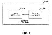
- Fig. 2is a schematic block diagram illustrating a context component for a graphical user interface system.
- Fig. 3is a diagram illustrating an example base presentation and overlay.
- Fig. 4is a diagram illustrating an alternative base presentation example and overlay.
- Fig. 5is a diagram illustrating an example system for presenting information to a user based in part on context and location.
- Fig. 6is a flow diagram illustrating an interface process for presenting information to a user in view of context and/or location.
- Fig. 7is a diagram illustrating an alternative system for presenting industrial control information to a user.
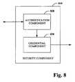
- Fig. 8is a diagram illustrating an example security component for identifying users and/or attributes.
- Fig. 9is an alternative processing system for presenting industrial control information to users.
- an industrial automation systemincludes a base presentation component to display one or more elements of an industrial control environment.
- Various display itemscan be dynamically superimposed on the base presentation component to provide industrial control information to a user.
- a location componentis provided to identify a physical or a virtual location for a user in an industrial control environment. This can include a context component to determine at least one attribute for the user in view of the physical or virtual location.
- a presentation componentthen provides information to the user based in part on the physical or virtual location and the determined attribute.
- a componentmay be, but is not limited to being, a process running on a processor, a processor, an object, an executable, a thread of execution, a program and a computer.
- an application running on a server and the servercan be components.
- One or more componentsmay reside within a process and/or thread of execution and a component may be localized on one computer and/or distributed between two or more computers, industrial controllers, and/or modules communicating therewith.
- a graphical user interface system 100is depicted for an industrial automation environment. It is contemplated that interface system 100 can form at least part of a human machine interface (HMI), but is not limited thereto. For example, the interface system 100 can be employed to facilitate viewing and interaction with data related to automation control systems, devices, and/or associated equipment (collectively referred to herein as an automation device(s)) forming part of a production environment.
- Interface system 100includes a display component 110, interaction component 120, base presentation component 130, item component 140, and context component 150.
- the display component 110can render a display to and/or receive data from a display device or component such as a monitor, television, computer, mobile device, web browser or the like.
- a display device or componentsuch as a monitor, television, computer, mobile device, web browser or the like.
- automation devices and information or data concerning automation devicescan be presented graphically in an easily comprehensible manner.
- the datacan be presented as one or more of alphanumeric characters, graphics, animations, audio and video.
- the datacan be static or updated dynamically to provide information in real-time as changes or events occur. Still further yet, one can interact with the interface 100 via the interaction component 120.
- the interaction component 120is communicatively coupled to the display component 110 and receives input concerning the displayed objects and information.
- Interaction component 120can receive input from a user, where user input can correspond to object identification, selection and/or interaction therewith.
- Various identification mechanismscan be employed. For example, user input can be based on positioning and/or clicking of a mouse, stylus, or trackball, and/or depression of keys on a keyboard or keypad with respect to displayed information.
- the display devicemay be by a touch screen device such that identification can be made based on touching a graphical object.
- Other input devicesare also contemplated including but not limited to gesture detection mechanisms (e.g. , pointing, gazing...) and voice recognition.
- inputcan correspond to entry or modification of data.
- Such inputcan affect the display and/or automation devices. For instance, a user could alter the display format, color or the like. Additionally or alternatively, a user could modify automation device parameters. By way of example and not limitation, a conveyor motor speed could be increased, decreased or halted.
- inputneed not come solely from a user, it can also be provided by automation devices. For example, warnings, alarms, and maintenance schedule information, among other things, can be provided with respect to displayed devices.
- the display component 110is also communicatively coupled to base presentation component 130 and item component 140.
- Base presentation component 130generates, receives, retrieves or otherwise obtains a graphical representation of a production environment including one or more objects representing, inter alia, devices, information pertaining to devices ( e.g. , gages, thermometers%) and the presentation itself.
- the base presentation provided by base presentation component 130can form all or part of the complete display rendered by the display component 110.
- one or more itemscan form part of the display.
- An itemis a graphical element or object that is superimposed on at least part of the base presentation or outside the boundaries of the base presentation.
- the itemcan provide information of interest and can correspond to an icon, a thumbnail, a dialog box, a tool tip, and a widget, among other things.
- the itemscan be transparent, translucent, or opaque be of various sizes, color, brightness, and so forth as well as be animated for example fading in and out.
- Icons itemscan be utilized to communicate the type of information being presented.
- Thumbnailscan be employed to present an overview of information or essential content. Thumbnails as well as other items can be a miniature but legible representation of information being presented and can be static or dynamically updating.
- Effects such as fade in and outcan be used to add or remove superimposed information without overly distracting a user's attention.
- itemscan gradually become larger/smaller, brighter/dimmer, more/less opaque or change color or position to attract more or less of a user's attention, thereby indicating increasing or decreasing importance of the information provided thereby.
- the positions of the itemscan also be used to convey one or more of locations of equipment relative to a user's current location or view, the position or index of a current task within a sequence of tasks, the ability to navigate forward or back to a previously visited presentation or view and the like.
- the usercan also execute some measure of control over the use/meaning of these various presentation techniques, for example via interface component 120.
- a usercan choose, via a variety of selection methods or mechanisms (e.g. , clicking, hovering, pointing%), to direct their attention to one or more items.
- the selected information, or item providing such informationcan become prominent within the presentation, allowing the user to view and interact with it in full detail.
- the informationmay change from static to active/dynamically updating upon selection. When the focus of the presentation changes in such a manner, different information may become more/less interesting or may no longer be of interest at all. Thus, both the base presentation and the set of one or more items providing interesting information can be updated when a user selects a new view.
- Context informationis provided by context component 150, which is communicatively coupled to display component 110.
- the context component 150can include a user component 210 and a device component 220.
- the user component 150can detect or determine context information regarding a user or users. Such information can include but is not limited to a user's identity, role, location (logical or physical), current activity, similar or previous interactions with automation devices.
- device component 220detects or determines context data pertaining to automation devices including control systems, devices and associated equipment.
- Device context datacan include but is not limited to logical/physical locations and operating status ( e.g. , on/off, healthy/faulty).
- the context component 130can provide the determined, detected or otherwise acquired context data to display component 110. Display component can then utilize such data in determining which base presentations and or items to display as well as their format and position.
- the system 100can determine and track their identity, their roles and responsibilities, their areas or regions of interest/responsibility and their activities. Similarly, the system can maintain information about devices/equipment that make up the automation control system, information such as logical/physical locations, operating status and the types of information that are of interest to different persons/roles. The system is then able to create mappings/linkages between these two sets of information and thus identify information germane to a user's current location and activities, among other things.
- Display 300includes a base presentation 310 comprising two tanks connected to a first valve and a first pump as well as a mixer, motor, a second value and a second pump.
- Base presentation 310also includes two gages associated with the motor identifying motor temperature and speed. As shown, the base presentation 310 does not occupy they entire display rather it is centered in the middle providing a border of free space.
- items 320-325are also displayed that provide related or situation specific information.
- Items 320 and 321are graphs of historical information and item 322 provides information regarding vibration analysis with respect a motor.
- Item 323indicates attention is required with respect to the associated pump and item 324 provides an indication that help information is available upon selection of the item, for instance.
- Item 325is shrunken representation of details regarding the base presentation 310.
- Items 320, 321, 322, and 325are superimposed on the display and are positioned along the periphery of the base presentation in accordance with an aspect of the invention. This positioning is beneficial at least because it does not obscure information provided by the base presentation 310.
- items 323 and 324are superimposed entirely over base presentation 310, but are small enough not to cover any objects provided thereby.
- a usercan interact with any of the display objects which may cause the display to change. For instance, if a user selects or otherwise identifies item 325 the display 400 of FIG. 4 could result. As illustrated by FIG. 4 , the interface system updates the base presentation 410 to show the selected information and automatically superimposes new, situation-specific information that is related to the updated display 400. In particular, items 410, 420 and 430 are displayed. Item 410 provides information regarding a shift production report and item 420 identifies that help is available for display upon selection, for example. Item 430 is a shrunken version of the previous base presentation 310 of Fig. 3 . The user can return to the previous base presentation 310 by selecting superimposed item 430.
- the system 500includes an information retrieval component 502 that is configured to obtain information regarding user(s) of the system 500, historical and real-time information relating to the user(s), device(s) and/or equipment(s).
- the information retrieval component 502can be further configured to make a determination or inference whether information should be presented to the user(s).
- One or more userscan physically and/or virtually ( e.g. , remotely) interact with and/or navigate through system 500.
- the information retrieval component 502obtains, receives, requests, and so forth information regarding each user 504.
- a means for identifying each user 504can be employed, such as a unique user name and/or password, for example.
- system 500can use alternative identifications means, such as biometric authentication that utilizes physical characteristic unique to individuals. It is to be appreciated that a plurality of identification schemes can be utilized with system 500 and all such alterations and modifications are intended to fall within the scope of the detailed description and appended claims.
- information retrieval component 502can determine and/or track the context of each user 504. This information can be retrieved from one or more database or other storage/retrieval means that can include a user/role context data component 510 and/or a user/role historical data component 512.
- the context of each usercan be, for example, the role, position, responsibilities, authorized programs, areas or regions of interest, activities, etc. as it relates to the particular user.
- the information retrieval component 502can further be configured to access historical data 506 from a device equipment context component 514 and/or a device/equipment historical component 516 that include data relating to device(s) and/or equipment.
- information regarding the devices and/or equipment that are included in the automation control systemcan include a plurality of information that is maintained and/or stored. Examples of maintained information include logical and/or physical locations, operating status, other types of information that are of interest to different users and/or user roles.
- an operator of the automation control systemmay have a direct area of interest than a tester and/or maintenance user because of the disparate role of each user and how/why each user interacts with system 500.
- the information retrieval component 502is further configured to update the historical data 506.
- the information retrieval component 502can also be configured to interact with real-time data 518 regarding the device(s) and/or equipment associated with system 500.
- One or more device, labeled Device 1 through Device N, and/or one or more equipment, labeled Equipment 1 through Equipment N, where N is an integercan be monitored for status information.
- real time datacan include the operating status of the device/equipment (e.g., off, on, run, ...), the current stage or process of each device/equipment ( e.g. , operating, line of code being implemented, ).
- the information retrieval component 502can make a determination whether a user 504 would be interested in information relating to a particular device/equipment and is able to create mappings and/or linkages between the two sets of information (historical 506 and real time 518) and identify or infer information that may be relevant to users' current locations and activities. For example, if there is an alarm on a device and/or piece of equipment, based on the user context, the user may be presented information relating to such alarm condition. If the user context and/or historical information indicate that the user 502 is not interested in the particular device and/or equipment, the information retrieval component 504 will not present such information to the user.
- This determinationcan be made based on the user role, context, historical, and other information obtained as well as the device/equipment context, historical, current, and other information. If a determination is made that one or more user 504 would be interested in such information, the information is presented to the one or more user interested in the data, as shown at 510.
- system 500can automatically present that operator with information about the current operational status of the devices and/or equipment located in the area in which the operator is located.
- system 500can present that user with information about the maintenance status of the devices and/or equipment located in that area at substantially the same time.
- an electrician working in the same areamight be presented with information about different devices and equipment, specifically, those related to the electrical systems in that area of the facility, at substantially the same time as the operator and maintenance engineer are presented information.
- Fig. 6illustrates a methodology 600 for presenting user(s) with information of interest. While, for purposes of simplicity of explanation, the methodology is shown and described as a series of acts, it is to be understood and appreciated that the methodology is not limited by the order of acts, as some acts may occur in different orders and/or concurrently with other acts from that shown and described herein. For example, those skilled in the art will understand and appreciate that a methodology could alternatively be represented as a series of interrelated states or events, such as in a state diagram. Moreover, not all illustrated acts may be required to implement a methodology as described herein.
- the method 600can identify the information of interest to one or more user without prompting or requesting such interest information from the user(s).
- the inferencecan be based on identity, role, location, and/or on text in a production facility by matching the user's location, context, and/or role with the location and/or status of device/equipment/system being monitored.
- the process 600begins at 602, where one or more users are identified.
- the identification of the usercan be performed utilizing a plurality of identification techniques and the disclosed aspects are not limited to any one known technique.
- user informationis retrieved, at 604, and can include contextual information and/or historical information.
- real-time data regarding the devices and/or equipmentis obtained.
- the methodcontinues, at 608, where a determination is made whether a user interest matches the device and/or equipment information obtained. For example, based on a user's context and/or historical information a determination or inference can be made that the user would be interested in information regarding device/equipment in a particular area of an industrial setting. If the determination or inference is that the user would most likely be interested in the information ("YES"), the method continues, at 608, where the information is presented to the user(s). It should be understood that more than one user can receive substantially the identical information or different information at substantially the same time. If the determination, at 608, is that the user is most likely not interested in the information ("NO"), the method 600 continue at 606 where real-time data is monitored for information that might of interest to one or more users.
- the system 700includes a presentation component 710 that produces and manages interaction with an element provided on a base display.
- the format of the element including the data to be supplied therewithcan be influenced by settings 720 and context component 730.
- connection component 740is provided to set up connections to one or more sources 750 to supply data to the element.
- the system 700can also include an update component 760.
- the update component 760can monitor one or more sources and detect changes to particular data being utilized by the presentation component 710 for an element. Hence, the update component 760 can be communicatively coupled to the presentation component 710 and connection component 740.
- the update component 760can receive, retrieve, or otherwise obtain the location and identity of data of interest from the presentation component 710 and can then monitor the particular source 750. If a change is detected, the update component 760 can inform the presentation component 710. Subsequently, the update component 760 can provide the presentation component 710 with the updated data or the presentation component can retrieve the data itself via the connection component 740. It should also be appreciated that this type of polling methodology can be executed by a source for example utilizing a serve-let, thereby eliminating the need for the update component 760 in certain instances.
- Fig. 8depicts a security component 810 that can be employed with the interfaces described herein.
- the security component 810can include an authentication component 820 and a credential component 830.
- the authentication component 820determines the identity of a user. For example, a user may be asked to furnish a user name and password. Authentication can also be accomplished by receiving a smart card to identify the user. Still further yet, the authentication component 820 can employ biometric authentication. Biometric authentication utilizes physical characteristic unique to individuals. For example, biometric authentication can include but is not limited to identifying a user via fingerprint, palm geometry, retina, facial features (e.g., 2-D, 3-D%), signature, typing pattern (e.g., speed, rhythm%), and/or voice recognition, among others.
- the authentication component 820provides the credential component 830 with the identity of the user.
- the credential component 830matches the user with particular credentials based on the individual user, group membership, or a position ( e.g. , administrator, manager%), inter alia.
- the credentialsspecify the type, class and/or category of information that a user can obtain, or alternatively is prohibited from receiving.
- Fig. 9illustrates an alternative system 900 for processing the interfaces described herein. Similar to Fig. 7 , the system 900 can include a presentation component 910. The presentation component 910 can generate and control interaction with one or more elements added to a base presentation. Settings 920 and context component 930 can be utilized to influence the format as well as the data provided by an element. Connection component 940 is communicatively coupled to the presentation component 910 and one or more sources 950 and is operable to establish a connection between the presentation component 910 and one or more data sources 950. An update component 960 monitors one or more data sources via the connection component 940 to enable detection of data changes and facilitate notification of the presentation component thereof, inter alia. The system 900 also includes a security component 970.
- the security component 970is communicatively coupled to presentation component 910 and facilitates control of data presented by elements. Accordingly, a mechanism is provided to ensure that at least some data is presented only to authorized or identified users.
- the security component 970can provide security credentials for a user to the presentation component 910.
- the presentation component 910can then present only data that is appropriate for the security level of the user, an associated group or position.
- the identity of the usercould come from outside the system 900 such as from computer or program login or the like.
- a componentcould request and receive information to enable a determination of a user's identity, for instance utilizing the security component 970.
- a graphical componentcould request a username and password.
- a usermay be asked to touch or gaze at the component to facilitate biometric identification.
- GUIGraphical User Interface
- Thiscan include substantially any type of application that sends, retrieves, processes, and/or manipulates factory input data, receives, displays, formats, and/or communicates output data, and/or facilitates operation of the enterprise.
- GUIGraphical User Interface
- the GUIcan include a display having one or more display objects (not shown) including such aspects as configurable icons, buttons, sliders, input boxes, selection options, menus, tabs and so forth having multiple configurable dimensions, shapes, colors, text, data and sounds to facilitate operations with the interfaces.
- GUIcan also include a plurality of other inputs or controls for adjusting and configuring one or more aspects. This can include receiving user commands from a mouse, keyboard, speech input, web site, remote web service and/or other device such as a camera or video input to affect or modify operations of the GUI.
- PLCcan include functionality that can be shared across multiple components, systems, and or networks.
- One or more PLCscan communicate and cooperate with various network devices across a network. This can include substantially any type of control, communications module, computer, I/O device, Human Machine Interface (HMI)) that communicate via the network which includes control, automation, and/or public networks.
- the PLCcan also communicate to and control various other devices such as Input/Output modules including Analog, Digital, Programmed/Intelligent I/O modules, other programmable controllers, communications modules, and the like.
- the network(not shown) can include public networks such as the Internet, Intranets, and automation networks such as Control and Information Protocol (CIP) networks including DeviceNet and ControlNet.
- CIPControl and Information Protocol
- Networksinclude Ethernet, DH/DH+, Remote I/O, Fieldbus, Modbus, Profibus, wireless networks, serial protocols, and so forth.
- the network devicescan include various possibilities (hardware and/or software components). These include components such as switches with virtual local area network (VLAN) capability, LANs, WANs, proxies, gateways, routers, firewalls, virtual private network (VPN) devices, servers, clients, computers, configuration tools, monitoring tools, and/or other devices.
- VLANvirtual local area network
- WANswide area network
- proxiesproxies
- gatewaysgateways
- routersfirewalls
- VPNvirtual private network
- an industrial automation systemin one aspect, includes a base presentation component to display one or more elements of an industrial control environment. Various display items can be dynamically superimposed on the base presentation component to provide industrial control information to a user.
- a location componentis provided to identify a physical or a virtual location for a user in an industrial control environment. This can include a context component to determine at least one attribute for the user in view of the physical or virtual location. A presentation component then provides information to the user based in part on the physical or virtual location and the determined attribute.
Landscapes
- Physics & Mathematics (AREA)
- General Physics & Mathematics (AREA)
- Engineering & Computer Science (AREA)
- Automation & Control Theory (AREA)
- User Interface Of Digital Computer (AREA)
- Digital Computer Display Output (AREA)
Description
- The subject invention relates generally to industrial control systems, and more particularly to various automated interfaces that interact with industrial control systems based in part on detected factors such as a user's role, identity, location, and so forth.
- Industrial controllers are special-purpose computers utilized for controlling industrial processes, manufacturing equipment, and other factory automation, such as data collection or networked systems. At the core of the industrial control system, is a logic processor such as a Programmable Logic Controller (PLC) or PC-based controller. Programmable Logic Controllers for instance, are programmed by systems designers to operate manufacturing processesvia user-designed logic programs or user programs. The user programs are stored in memory and generally executed by the PLC in a sequential manner although instruction jumping, looping and interrupt routines, for example, are also common. Associated with the user program are a plurality of memory elements or variables that provide dynamics to PLC operations and programs. Differences in PLCs are typically dependent on the number of Input/Output (I/O) they can process, amount of memory, number and type of instructions, and speed of the PLC central processing unit (CPU).
- One area that has grown in recent years is the need for humans to interact with industrial control systems in the course of business operations. This includes employment of human machine interfaces (HMI) to facilitate operations with such systems, where the HMI can be provided as a graphical user interface in one form. Traditional HMI/automation control systems are generally limited in their ability to make users aware of situations that require their attention or of information that may be of interest to them relative to their current tasks. Where such mechanisms do exist, they tend to be either overly intrusive (e.g., interrupting the user's current activity by "popping up" an alarm display on top of whatever they were currently looking at) or not informative enough (e.g., indicating that something requires the user's attention but not providing information about what). Often times, the user must navigate to another display (e.g., a "detail screen", "alarm summary" or "help screen") to determine the nature of the information or even to determine whether such information exists. As can be appreciated, navigation and dealing with pop-ups is time consuming and costly.
- In other conventional HMI/automation control systems, information that is presented to users must be preconfigured by a control system designer and must be explicitly requested the user. For example, when an alarm condition occurs and the user wants additional information to help them diagnose/resolve the issue, they must explicitly ask the system to provide it. For this to occur, several conditions should be true: (1) when the control system was designed, the designer must have thought to make that specific information available to that user/role and for that specific situation; (2) the user must know that such information exists; and (3) the user must ask the system to fetch and display that information.
WO 99/39276 A GB 2 407 243 A US 2003/036808 A1 relates to a board work system operable by a plurality of operators assigned in turn to operate. The system includes at least one device, changeable to each one of a plurality of different modes, and a control device which controls the changeable device and receives operator ID data identifying each operator so as to recognize which one of the operators is currently assigned to operate the system. It is considered preferable to limit commands acceptable by the control device depending on ability, job position and other characteristics of the currently assigned operator. Namely, the corresponding device of the control device is preferably placed in such a mode that validates one or ones of the commands which are really required for the currently assigned operator. In the conventional circuit-board work system, a password has to be supplied to the control device to establish the special mode validating the special commands, for example in the event of a failure of the system.- The following presents a simplified summary in order to provide a basis understanding of some aspects described herein. This summary is not an extensive overview nor is intended to identify key/critical element or to delineate the scope of the various aspects described herein. Its sole purpose is to present some concepts in a simplified form as a prelude to the more detailed description that is presented later.
- It is the object of the present invention to provide various interface applications to facilitate more efficient interactions with industrial automation system.
- This object is solved by the subject matter of the independent claims.
- Embodiments are given in the dependent claims.
- In one aspect, systems and methods are provided to mitigate navigation issues with human machine interfaces (HMI) and/or pop-up problems associated with such interfaces. By exploiting situation-specific data or "information of interest",e.g., based on factors such as the user's identity, role, location (logical or physical), current task, current view, and so forth, an HMI can be provided to superimpose such situation-specific information upon the user's current view of the automation control system ("base presentation") in a manner that communicates the essence of information as well as its importance/priority/urgency without completely dominating the user's attention or interrupting their current interaction with the system. In this manner, problems dealing with excessive navigation or obtrusive displays can be mitigated.
- In another aspect, systems and methods are provided for mitigating pre-configuration interface issues by automatically providing users with relevant, situation-specific information. This includes automatically locating information that may be of interest/use in a user's current situation by matching attributes such as the user's identity, role, location (logical or physical), current activity, similar previous (historical) situations/activities, and so forth with other data such as device/equipment locations, device/equipment status, user/role/situation-specific reports, user-documentation, training manuals, and so forth. Thus, the user is automatically provided a rich set of information related to their current task/situation without generally requiring that person/situation/information mappings be predefined by control system designers.
- To the accomplishment of the foregoing and related ends, certain illustrative aspects are described herein in connection with the following description and the annexed drawings. These aspects are indicative of various ways which can be practiced, all of which are intended to be covered herein. Other advantages and novel features may become apparent from the following detailed description when considered in conjunction with the drawings.
Fig. 1 is a schematic block diagram illustrating a graphical user interface system.Fig. 2 is a schematic block diagram illustrating a context component for a graphical user interface system.Fig. 3 is a diagram illustrating an example base presentation and overlay.Fig. 4 is a diagram illustrating an alternative base presentation example and overlay.Fig. 5 is a diagram illustrating an example system for presenting information to a user based in part on context and location.Fig. 6 is a flow diagram illustrating an interface process for presenting information to a user in view of context and/or location.Fig. 7 is a diagram illustrating an alternative system for presenting industrial control information to a user.Fig. 8 is a diagram illustrating an example security component for identifying users and/or attributes.Fig. 9 is an alternative processing system for presenting industrial control information to users.- Systems and methods are provided that enable various interface applications that more efficiently communicate data to users in an industrial control system. In one aspect, an industrial automation system is provided. The system includes a base presentation component to display one or more elements of an industrial control environment. Various display items can be dynamically superimposed on the base presentation component to provide industrial control information to a user. In another aspect of the industrial automation system, a location component is provided to identify a physical or a virtual location for a user in an industrial control environment. This can include a context component to determine at least one attribute for the user in view of the physical or virtual location. A presentation component then provides information to the user based in part on the physical or virtual location and the determined attribute.
- It is noted that as used in this application, terms such as "component," "display," "interface, " and the like are intended to refer to a computer-related entity, either hardware, a combination of hardware and software, software, or software in execution as applied to an automation system for industrial control. For example, a component may be, but is not limited to being, a process running on a processor, a processor, an object, an executable, a thread of execution, a program and a computer. By way of illustration, both an application running on a server and the server can be components. One or more components may reside within a process and/or thread of execution and a component may be localized on one computer and/or distributed between two or more computers, industrial controllers, and/or modules communicating therewith.
- Referring initially to
Fig. 1 , a graphicaluser interface system 100 is depicted for an industrial automation environment. It is contemplated thatinterface system 100 can form at least part of a human machine interface (HMI), but is not limited thereto. For example, theinterface system 100 can be employed to facilitate viewing and interaction with data related to automation control systems, devices, and/or associated equipment (collectively referred to herein as an automation device(s)) forming part of a production environment.Interface system 100 includes adisplay component 110,interaction component 120,base presentation component 130,item component 140, andcontext component 150. - The
display component 110 can render a display to and/or receive data from a display device or component such as a monitor, television, computer, mobile device, web browser or the like. In particular, automation devices and information or data concerning automation devices can be presented graphically in an easily comprehensible manner. The data can be presented as one or more of alphanumeric characters, graphics, animations, audio and video. Furthermore, the data can be static or updated dynamically to provide information in real-time as changes or events occur. Still further yet, one can interact with theinterface 100 via theinteraction component 120. - The
interaction component 120 is communicatively coupled to thedisplay component 110 and receives input concerning the displayed objects and information.Interaction component 120 can receive input from a user, where user input can correspond to object identification, selection and/or interaction therewith. Various identification mechanisms can be employed. For example, user input can be based on positioning and/or clicking of a mouse, stylus, or trackball, and/or depression of keys on a keyboard or keypad with respect to displayed information. Furthermore, the display device may be by a touch screen device such that identification can be made based on touching a graphical object. Other input devices are also contemplated including but not limited to gesture detection mechanisms (e.g., pointing, gazing...) and voice recognition. - In addition to object or information selection, input can correspond to entry or modification of data. Such input can affect the display and/or automation devices. For instance, a user could alter the display format, color or the like. Additionally or alternatively, a user could modify automation device parameters. By way of example and not limitation, a conveyor motor speed could be increased, decreased or halted. It should be noted that input need not come solely from a user, it can also be provided by automation devices. For example, warnings, alarms, and maintenance schedule information, among other things, can be provided with respect to displayed devices.
- The
display component 110 is also communicatively coupled tobase presentation component 130 anditem component 140.Base presentation component 130 generates, receives, retrieves or otherwise obtains a graphical representation of a production environment including one or more objects representing, inter alia, devices, information pertaining to devices (e.g., gages, thermometers...) and the presentation itself. In accordance with one aspect, the base presentation provided bybase presentation component 130 can form all or part of the complete display rendered by thedisplay component 110. In addition to the base presentation, one or more items can form part of the display. - An item is a graphical element or object that is superimposed on at least part of the base presentation or outside the boundaries of the base presentation. The item can provide information of interest and can correspond to an icon, a thumbnail, a dialog box, a tool tip, and a widget, among other things. The items can be transparent, translucent, or opaque be of various sizes, color, brightness, and so forth as well as be animated for example fading in and out. Icons items can be utilized to communicate the type of information being presented. Thumbnails can be employed to present an overview of information or essential content. Thumbnails as well as other items can be a miniature but legible representation of information being presented and can be static or dynamically updating. Effects such as fade in and out can be used to add or remove superimposed information without overly distracting a user's attention. In addition, items can gradually become larger/smaller, brighter/dimmer, more/less opaque or change color or position to attract more or less of a user's attention, thereby indicating increasing or decreasing importance of the information provided thereby. The positions of the items can also be used to convey one or more of locations of equipment relative to a user's current location or view, the position or index of a current task within a sequence of tasks, the ability to navigate forward or back to a previously visited presentation or view and the like. The user can also execute some measure of control over the use/meaning of these various presentation techniques, for example via
interface component 120. - If desired, a user can choose, via a variety of selection methods or mechanisms (e.g., clicking, hovering, pointing...), to direct their attention to one or more items. In this case the selected information, or item providing such information, can become prominent within the presentation, allowing the user to view and interact with it in full detail. In some cases, the information may change from static to active/dynamically updating upon selection. When the focus of the presentation changes in such a manner, different information may become more/less interesting or may no longer be of interest at all. Thus, both the base presentation and the set of one or more items providing interesting information can be updated when a user selects a new view.
- The items and base presentation provided for display can be affected by context. Context information is provided by
context component 150, which is communicatively coupled todisplay component 110. Turning briefly toFIG. 2 acontext component 150 is illustrated in further detail. Thecontext component 150 can include auser component 210 and adevice component 220. Theuser component 150 can detect or determine context information regarding a user or users. Such information can include but is not limited to a user's identity, role, location (logical or physical), current activity, similar or previous interactions with automation devices. Similarly,device component 220 detects or determines context data pertaining to automation devices including control systems, devices and associated equipment. Device context data can include but is not limited to logical/physical locations and operating status (e.g., on/off, healthy/faulty...). Returning toFIG. 1 , thecontext component 130 can provide the determined, detected or otherwise acquired context data to displaycomponent 110. Display component can then utilize such data in determining which base presentations and or items to display as well as their format and position. - By way of example, as a user navigates through interface system 100 (physically or virtually), the
system 100 can determine and track their identity, their roles and responsibilities, their areas or regions of interest/responsibility and their activities. Similarly, the system can maintain information about devices/equipment that make up the automation control system, information such as logical/physical locations, operating status and the types of information that are of interest to different persons/roles. The system is then able to create mappings/linkages between these two sets of information and thus identify information germane to a user's current location and activities, among other things. - Turning to
Fig. 3 , anexemplary display 300 is depicted thatdisplay component 110 ofFig. 1 may render. It should be appreciated that display 300 (as well asdisplay 400 ofFIG. 4 ) is provided solely facilitate clarity and understanding with respect to various aspects of the subject disclosure and is therefore not meant to limit the subject invention in any manner.Display 300 includes abase presentation 310 comprising two tanks connected to a first valve and a first pump as well as a mixer, motor, a second value and a second pump.Base presentation 310 also includes two gages associated with the motor identifying motor temperature and speed. As shown, thebase presentation 310 does not occupy they entire display rather it is centered in the middle providing a border of free space. In addition tobase presentation 310, various items 320-325 are also displayed that provide related or situation specific information.Items item 322 provides information regarding vibration analysis with respect a motor.Item 323 indicates attention is required with respect to the associated pump anditem 324 provides an indication that help information is available upon selection of the item, for instance.Item 325 is shrunken representation of details regarding thebase presentation 310.Items base presentation 310. By contrast,items base presentation 310, but are small enough not to cover any objects provided thereby. - A user can interact with any of the display objects which may cause the display to change. For instance, if a user selects or otherwise identifies
item 325 thedisplay 400 ofFIG. 4 could result. As illustrated byFIG. 4 , the interface system updates thebase presentation 410 to show the selected information and automatically superimposes new, situation-specific information that is related to the updateddisplay 400. In particular,items Item 410 provides information regarding a shift production report anditem 420 identifies that help is available for display upon selection, for example.Item 430 is a shrunken version of theprevious base presentation 310 ofFig. 3 . The user can return to theprevious base presentation 310 by selecting superimposeditem 430. - Referring now to
Fig. 5 , anexample system 500 is illustrated for dynamically presenting information of interest to one or more users in an industrial automation environment. Thesystem 500 includes aninformation retrieval component 502 that is configured to obtain information regarding user(s) of thesystem 500, historical and real-time information relating to the user(s), device(s) and/or equipment(s). Theinformation retrieval component 502 can be further configured to make a determination or inference whether information should be presented to the user(s). - One or more users, illustrated at 504 as
User 1 through User N, where N is an integer equal to or greater than one, can physically and/or virtually (e.g., remotely) interact with and/or navigate throughsystem 500. As the user(s) 504 contacts thesystem 500, theinformation retrieval component 502 obtains, receives, requests, and so forth information regarding eachuser 504. A means for identifying eachuser 504 can be employed, such as a unique user name and/or password, for example. In other aspects,system 500 can use alternative identifications means, such as biometric authentication that utilizes physical characteristic unique to individuals. It is to be appreciated that a plurality of identification schemes can be utilized withsystem 500 and all such alterations and modifications are intended to fall within the scope of the detailed description and appended claims. - Utilizing the user identification,
information retrieval component 502 can determine and/or track the context of eachuser 504. This information can be retrieved from one or more database or other storage/retrieval means that can include a user/rolecontext data component 510 and/or a user/rolehistorical data component 512. The context of each user can be, for example, the role, position, responsibilities, authorized programs, areas or regions of interest, activities, etc. as it relates to the particular user. - The
information retrieval component 502 can further be configured to accesshistorical data 506 from a deviceequipment context component 514 and/or a device/equipmenthistorical component 516 that include data relating to device(s) and/or equipment. For example, information regarding the devices and/or equipment that are included in the automation control system can include a plurality of information that is maintained and/or stored. Examples of maintained information include logical and/or physical locations, operating status, other types of information that are of interest to different users and/or user roles. For example, an operator of the automation control system may have a direct area of interest than a tester and/or maintenance user because of the disparate role of each user and how/why each user interacts withsystem 500. Theinformation retrieval component 502 is further configured to update thehistorical data 506. - The
information retrieval component 502 can also be configured to interact with real-time data 518 regarding the device(s) and/or equipment associated withsystem 500. One or more device, labeledDevice 1 through Device N, and/or one or more equipment, labeledEquipment 1 through Equipment N, where N is an integer can be monitored for status information. For example, real time data can include the operating status of the device/equipment (e.g., off, on, run, ...), the current stage or process of each device/equipment (e.g., operating, line of code being implemented, ...). - The
information retrieval component 502 can make a determination whether auser 504 would be interested in information relating to a particular device/equipment and is able to create mappings and/or linkages between the two sets of information (historical 506 and real time 518) and identify or infer information that may be relevant to users' current locations and activities. For example, if there is an alarm on a device and/or piece of equipment, based on the user context, the user may be presented information relating to such alarm condition. If the user context and/or historical information indicate that theuser 502 is not interested in the particular device and/or equipment, theinformation retrieval component 504 will not present such information to the user. This determination can be made based on the user role, context, historical, and other information obtained as well as the device/equipment context, historical, current, and other information. If a determination is made that one ormore user 504 would be interested in such information, the information is presented to the one or more user interested in the data, as shown at 510. - By way of example and not limitation, if an operator is working in the bottling area of a brewery,
system 500 can automatically present that operator with information about the current operational status of the devices and/or equipment located in the area in which the operator is located. Similarly, if a maintenance engineer is currently working in the same area, thesystem 500 can present that user with information about the maintenance status of the devices and/or equipment located in that area at substantially the same time. In addition or alternatively, an electrician working in the same area might be presented with information about different devices and equipment, specifically, those related to the electrical systems in that area of the facility, at substantially the same time as the operator and maintenance engineer are presented information. Fig. 6 illustrates amethodology 600 for presenting user(s) with information of interest. While, for purposes of simplicity of explanation, the methodology is shown and described as a series of acts, it is to be understood and appreciated that the methodology is not limited by the order of acts, as some acts may occur in different orders and/or concurrently with other acts from that shown and described herein. For example, those skilled in the art will understand and appreciate that a methodology could alternatively be represented as a series of interrelated states or events, such as in a state diagram. Moreover, not all illustrated acts may be required to implement a methodology as described herein.- The
method 600 can identify the information of interest to one or more user without prompting or requesting such interest information from the user(s). The inference can be based on identity, role, location, and/or on text in a production facility by matching the user's location, context, and/or role with the location and/or status of device/equipment/system being monitored. - The
process 600 begins at 602, where one or more users are identified. The identification of the user can be performed utilizing a plurality of identification techniques and the disclosed aspects are not limited to any one known technique. Based on the user identification, user information is retrieved, at 604, and can include contextual information and/or historical information. At 606, real-time data regarding the devices and/or equipment is obtained. - The method continues, at 608, where a determination is made whether a user interest matches the device and/or equipment information obtained. For example, based on a user's context and/or historical information a determination or inference can be made that the user would be interested in information regarding device/equipment in a particular area of an industrial setting. If the determination or inference is that the user would most likely be interested in the information ("YES"), the method continues, at 608, where the information is presented to the user(s). It should be understood that more than one user can receive substantially the identical information or different information at substantially the same time. If the determination, at 608, is that the user is most likely not interested in the information ("NO"), the
method 600 continue at 606 where real-time data is monitored for information that might of interest to one or more users. It is to be understood that this act can be recursive such that any number of devices/equipment can be polled for information. Moreover, it is to be appreciated that automated and/or dynamic polling of device/equipment can be employed in connection with alternate aspects. For example, the system can be configured to automatically poll and/or report device/equipment information dynamically in accordance with inferring a user interest in such information. Before proceeding, it is noted thatFigs. 6-9 and the associated discussion are provided to add alternative role-based and HMI processing environments for the above described systems and methods. - Turning to
Fig. 7 , analternative system 700 is provided for manipulating or processing user interface applications. Thesystem 700 includes apresentation component 710 that produces and manages interaction with an element provided on a base display. The format of the element including the data to be supplied therewith can be influenced bysettings 720 andcontext component 730. Additionally,connection component 740 is provided to set up connections to one ormore sources 750 to supply data to the element. Thesystem 700 can also include anupdate component 760. Theupdate component 760 can monitor one or more sources and detect changes to particular data being utilized by thepresentation component 710 for an element. Hence, theupdate component 760 can be communicatively coupled to thepresentation component 710 andconnection component 740. Theupdate component 760 can receive, retrieve, or otherwise obtain the location and identity of data of interest from thepresentation component 710 and can then monitor theparticular source 750. If a change is detected, theupdate component 760 can inform thepresentation component 710. Subsequently, theupdate component 760 can provide thepresentation component 710 with the updated data or the presentation component can retrieve the data itself via theconnection component 740. It should also be appreciated that this type of polling methodology can be executed by a source for example utilizing a serve-let, thereby eliminating the need for theupdate component 760 in certain instances. Fig. 8 depicts asecurity component 810 that can be employed with the interfaces described herein. Thesecurity component 810 can include anauthentication component 820 and acredential component 830. Theauthentication component 820 determines the identity of a user. For example, a user may be asked to furnish a user name and password. Authentication can also be accomplished by receiving a smart card to identify the user. Still further yet, theauthentication component 820 can employ biometric authentication. Biometric authentication utilizes physical characteristic unique to individuals. For example, biometric authentication can include but is not limited to identifying a user via fingerprint, palm geometry, retina, facial features (e.g., 2-D, 3-D...), signature, typing pattern (e.g., speed, rhythm...), and/or voice recognition, among others. Theauthentication component 820 provides thecredential component 830 with the identity of the user. Thecredential component 830 matches the user with particular credentials based on the individual user, group membership, or a position (e.g., administrator, manager...), inter alia. The credentials specify the type, class and/or category of information that a user can obtain, or alternatively is prohibited from receiving.Fig. 9 illustrates analternative system 900 for processing the interfaces described herein. Similar toFig. 7 , thesystem 900 can include apresentation component 910. Thepresentation component 910 can generate and control interaction with one or more elements added to a base presentation.Settings 920 andcontext component 930 can be utilized to influence the format as well as the data provided by an element.Connection component 940 is communicatively coupled to thepresentation component 910 and one ormore sources 950 and is operable to establish a connection between thepresentation component 910 and one ormore data sources 950. Anupdate component 960 monitors one or more data sources via theconnection component 940 to enable detection of data changes and facilitate notification of the presentation component thereof, inter alia. Thesystem 900 also includes asecurity component 970. Thesecurity component 970 is communicatively coupled topresentation component 910 and facilitates control of data presented by elements. Accordingly, a mechanism is provided to ensure that at least some data is presented only to authorized or identified users. By way of example, thesecurity component 970 can provide security credentials for a user to thepresentation component 910. Thepresentation component 910 can then present only data that is appropriate for the security level of the user, an associated group or position. The identity of the user could come from outside thesystem 900 such as from computer or program login or the like. Alternatively, a component could request and receive information to enable a determination of a user's identity, for instance utilizing thesecurity component 970. For example, a graphical component could request a username and password. Alternatively, a user may be asked to touch or gaze at the component to facilitate biometric identification.- It is noted that the interfaces described herein can include a Graphical User Interface (GUI) to interact with the various components for providing industrial control information to users. This can include substantially any type of application that sends, retrieves, processes, and/or manipulates factory input data, receives, displays, formats, and/or communicates output data, and/or facilitates operation of the enterprise. For example, such interfaces can also be associated with an engine, editor tool or web browser although other type applications can be utilized. The GUI can include a display having one or more display objects (not shown) including such aspects as configurable icons, buttons, sliders, input boxes, selection options, menus, tabs and so forth having multiple configurable dimensions, shapes, colors, text, data and sounds to facilitate operations with the interfaces. In addition, the GUI can also include a plurality of other inputs or controls for adjusting and configuring one or more aspects. This can include receiving user commands from a mouse, keyboard, speech input, web site, remote web service and/or other device such as a camera or video input to affect or modify operations of the GUI.
- It is also noted that the term PLC as used herein can include functionality that can be shared across multiple components, systems, and or networks. One or more PLCs can communicate and cooperate with various network devices across a network. This can include substantially any type of control, communications module, computer, I/O device, Human Machine Interface (HMI)) that communicatevia the network which includes control, automation, and/or public networks. The PLC can also communicate to and control various other devices such as Input/Output modules including Analog, Digital, Programmed/Intelligent I/O modules, other programmable controllers, communications modules, and the like. The network (not shown) can include public networks such as the Internet, Intranets, and automation networks such as Control and Information Protocol (CIP) networks including DeviceNet and ControlNet. Other networks include Ethernet, DH/DH+, Remote I/O, Fieldbus, Modbus, Profibus, wireless networks, serial protocols, and so forth. In addition, the network devices can include various possibilities (hardware and/or software components). These include components such as switches with virtual local area network (VLAN) capability, LANs, WANs, proxies, gateways, routers, firewalls, virtual private network (VPN) devices, servers, clients, computers, configuration tools, monitoring tools, and/or other devices.
- What has been described above includes various exemplary aspects. It is, of course, not possible to describe every conceivable combination of components or methodologies for purposes of describing these aspects, but one of ordinary skill in the art may recognize that many further combinations and permutations are possible. Accordingly, the aspects described herein are intended to embrace all such alterations, modifications and variations that fall within the scope of the appended claims. Furthermore, to the extent that the term "includes" is used in either the detailed description or the claims, such term is intended to be inclusive in a manner similar to the term "comprising" as "comprising" is interpreted when employed as a transitional word in a claim.
In summary systems and methods are provided that enable various interface applications that more efficiently communicate data to users in an industrial control system. In one aspect, an industrial automation system is provided. The system includes a base presentation component to display one or more elements of an industrial control environment. Various display items can be dynamically superimposed on the base presentation component to provide industrial control information to a user. In another aspect of the industrial automation system, a location component is provided to identify a physical or a virtual location for a user in an industrial control environment. This can include a context component to determine at least one attribute for the user in view of the physical or virtual location. A presentation component then provides information to the user based in part on the physical or virtual location and the determined attribute.
Claims (9)
- An industrial automation system, comprising:an information retrieval component (502) adapted to retrieve context and historical information (506) about a user of the system, to interact with real-time data (518) regarding devices associated with the system, to create mappings between the historical information and the real-time data, and to determine whether information relating to a particular device of an industrial control environment is relevant to a user's current location and activity, on the basis of the user context and historical information;at least one base presentation component (130) adapted to display a graphical representation of the industrial control environment; andone or more display items (320-325, 410-430) adapted to automatically present the relevant information relating to the particular device to the user, the one or more display items being dynamically superimposed on the graphical representation of the industrial control environment to provide industrial control information to the user.
- The system of claim 1, further comprising an interaction component (120) that receives input concerning one or more display objects and information associated to the display objects.
- The system of claim 2, further comprising at least one identification component for at least one user.
- The system of claim 1, 2 or 3 the base presentation component generates, receives, retrieves or obtains a graphical representation of a production environment including one or more objects representing devices or information pertaining to the devices.
- The system of one of claims 1 to 4, further comprising a component to adjust the data items to be viewed as larger or smaller displays, brighter or dimmer displays, opaque displays, or changing color displays to attract more or less of a user's attention, and indicating increasing or decreasing importance of displayed information.
- The system of one of claims 1 to 5, further comprising a component that adjusts positions of the data items to convey one or more of locations of equipment relative to a user's current location or view, the position or index of a current task within a sequence of tasks, or an ability to navigate forward or back to a previously visited presentation or view.
- The system of one of claims 1 to 6, further comprising a component to create mappings or linkages between at least two sets of information and identify information germane to a user's current location or activity.
- A method to generate an industrial control interface, comprising:generating one or more base presentations for a given context of an industrial control system;determining (604) current context information (506) and historical information (506) about a user;interacting with real-time data (518) regarding devices associated with the system;creating mappings between the historical information and the real-time data;determining whether information relating to a particular device of the industrial control system is relevant to a user's current location and activity, on the basis of the user's current context and historical information; andautomatically presenting (610) the relevant information relating to the particular device to the user, the relevant information being displayed as display items dynamically superimposed on the one or more base presentations for the given context of the industrial control system.
- A computer readable medium storing computer-readable instructions that, when carried out by a processor, cause the processor to perform the method of claim 8.
Applications Claiming Priority (1)
| Application Number | Priority Date | Filing Date | Title |
|---|---|---|---|
| US11/239,899US7433741B2 (en) | 2005-09-30 | 2005-09-30 | Hybrid user interface having base presentation information with variably prominent supplemental information |
Publications (3)
| Publication Number | Publication Date |
|---|---|
| EP1772784A2 EP1772784A2 (en) | 2007-04-11 |
| EP1772784A3 EP1772784A3 (en) | 2009-12-09 |
| EP1772784B1true EP1772784B1 (en) | 2013-04-24 |
Family
ID=37642379
Family Applications (1)
| Application Number | Title | Priority Date | Filing Date |
|---|---|---|---|
| EP06020454.2ARevokedEP1772784B1 (en) | 2005-09-30 | 2006-09-28 | Hybrid user interface with base presentation components and supplemental information components |
Country Status (4)
| Country | Link |
|---|---|
| US (2) | US7433741B2 (en) |
| EP (1) | EP1772784B1 (en) |
| CN (1) | CN100549879C (en) |
| SG (1) | SG131103A1 (en) |
Families Citing this family (37)
| Publication number | Priority date | Publication date | Assignee | Title |
|---|---|---|---|---|
| GB0206338D0 (en)* | 2002-03-18 | 2002-05-01 | Aes Eng Ltd | Product selection |
| US7433741B2 (en)* | 2005-09-30 | 2008-10-07 | Rockwell Automation Technologies, Inc. | Hybrid user interface having base presentation information with variably prominent supplemental information |
| US20070078535A1 (en)* | 2005-09-30 | 2007-04-05 | Rockwell Automation Technologies, Inc. | System and method for identifying particularized equipment information of interest to varied users in an industrial automation environment |
| US20090271739A1 (en)* | 2006-07-20 | 2009-10-29 | Matsushita Electric Industrial Co., Ltd. | Input control unit |
| US20080092067A1 (en)* | 2006-10-16 | 2008-04-17 | Invensys Systems, Inc. | Custom properties for automation control |
| US9760076B2 (en)* | 2007-03-14 | 2017-09-12 | Phoenix Contact Gmbh & Co. Kg | Method, control device and control system for the control of an automation system |
| US8191005B2 (en) | 2007-09-27 | 2012-05-29 | Rockwell Automation Technologies, Inc. | Dynamically generating visualizations in industrial automation environment as a function of context and state information |
| US8026933B2 (en)* | 2007-09-27 | 2011-09-27 | Rockwell Automation Technologies, Inc. | Visualization system(s) and method(s) for preserving or augmenting resolution and data associated with zooming or paning in an industrial automation environment |
| US20090228963A1 (en)* | 2007-11-26 | 2009-09-10 | Nortel Networks Limited | Context-based network security |
| JP5116514B2 (en)* | 2008-03-11 | 2013-01-09 | キヤノン株式会社 | Imaging apparatus and display control method |
| US8624921B2 (en)* | 2008-09-30 | 2014-01-07 | Rockwell Automation Technologies, Inc. | Industrial automation visualization schemes employing overlays |
| US9043003B2 (en)* | 2009-07-31 | 2015-05-26 | Fisher-Rosemount Systems, Inc. | Graphical view sidebar for a process control system |
| US9164501B2 (en)* | 2009-10-05 | 2015-10-20 | Fisher-Rosemount Systems, Inc. | Methods and apparatus to manage data uploading in a process control environment |
| WO2011079300A2 (en)* | 2009-12-23 | 2011-06-30 | Comau, Inc. | Universal human machine interface for automation installation |
| US8766794B2 (en)* | 2010-07-28 | 2014-07-01 | Fisher-Rosemount Systems, Inc. | Handheld field maintenance tool with improved locational awareness functionality |
| EP2418554A1 (en)* | 2010-08-02 | 2012-02-15 | ABB Research Ltd. | Method and computer program products for enabling supervision and control of a technical system |
| EP2685329B1 (en)* | 2012-07-11 | 2015-09-23 | ABB Research Ltd. | Presenting process data of a process control object on a mobile terminal |
| EP2746883B1 (en) | 2012-12-18 | 2016-04-27 | Siemens Aktiengesellschaft | Method and server for generating a display and control display for an operating and observation device of an industrial automation assembly |
| US9690285B2 (en)* | 2013-02-27 | 2017-06-27 | Abb Schweiz Ag | Presenting field users on process graphics |
| US9806933B2 (en) | 2013-03-13 | 2017-10-31 | Microsoft Technology Licensing, Llc | Component loading based on user interactions |
| US9424411B2 (en)* | 2013-05-23 | 2016-08-23 | Honeywell International Inc. | Athentication of device users by gaze |
| US20140359458A1 (en)* | 2013-05-31 | 2014-12-04 | Ge Intelligent Platforms, Inc. | Providing a hybrid fieldbus device management application |
| US20140358251A1 (en)* | 2013-05-31 | 2014-12-04 | Ge Intelligent Platforms, Inc. | Incorporating fdt/dtm technology into a system-level configuration application for integrated device configuration management |
| DE102013013343A1 (en)* | 2013-08-09 | 2015-02-12 | Avelon Cetex AG | Method and device for operating an automation system |
| US10348561B1 (en) | 2013-11-20 | 2019-07-09 | Rockwell Automation, Inc. | Systems and methods for automated access to relevant information in a mobile computing environment |
| KR20150118278A (en)* | 2014-04-11 | 2015-10-22 | 엘지전자 주식회사 | Remote maintenance server, total maintenance system including the remote maintenance server and method thereof |
| US10053112B2 (en)* | 2014-09-04 | 2018-08-21 | GM Global Technology Operations LLC | Systems and methods for suggesting and automating actions within a vehicle |
| AU2016257463A1 (en)* | 2015-05-04 | 2017-12-07 | ContextLogic Inc. | Systems and techniques for presenting and rating items in an online marketplace |
| US20160349931A1 (en)* | 2015-05-28 | 2016-12-01 | Rockwell Automation Technologies, Inc. | Responsive user interface for an industrial environment |
| US20160378089A1 (en)* | 2015-06-24 | 2016-12-29 | Siemens Aktiengesellschaft | Logical Position Sensor |
| US10068376B2 (en)* | 2016-01-11 | 2018-09-04 | Microsoft Technology Licensing, Llc | Updating mixed reality thumbnails |
| CN106127002A (en)* | 2016-06-21 | 2016-11-16 | 京东方科技集团股份有限公司 | Display packing and display system |
| CN107092507B (en)* | 2017-04-18 | 2020-12-18 | 杭州云永网络科技有限公司 | Application program skin changing method, device and system |
| DE112017007717T5 (en)* | 2017-08-01 | 2020-03-26 | Ford Global Technologies, Llc | ROLE-BASED DYNAMIC UPDATE FROM HMI CONTEXT |
| US11237576B2 (en)* | 2017-08-03 | 2022-02-01 | Johnson Controls Tyco IP Holdings LLP | HVAC system with data driven user interfaces for equipment commissioning and operation |
| US20190114130A1 (en)* | 2017-10-18 | 2019-04-18 | Valmet Automation Oy | Industrial process control system |
| JP2019179476A (en)* | 2018-03-30 | 2019-10-17 | オムロン株式会社 | Support apparatus, support program, and setting method |
Family Cites Families (75)
| Publication number | Priority date | Publication date | Assignee | Title |
|---|---|---|---|---|
| US4370706A (en)* | 1980-09-26 | 1983-01-25 | The Bendix Corporation | Controller for a dual servo system |
| US5206568A (en)* | 1986-03-26 | 1993-04-27 | Beckman Instruments, Inc. | Coordinated control of stepper motors |
| GB2272325B (en)* | 1989-11-02 | 1994-09-28 | Combustion Eng | Plant monitor system |
| US5119079A (en)* | 1990-09-17 | 1992-06-02 | Xerox Corporation | Touch screen user interface with expanding touch locations for a reprographic machine |
| US5446903A (en) | 1993-05-04 | 1995-08-29 | International Business Machines Corporation | Method and apparatus for controlling access to data elements in a data processing system based on status of an industrial process by mapping user's security categories and industrial process steps |
| US5675752A (en)* | 1994-09-15 | 1997-10-07 | Sony Corporation | Interactive applications generator for an interactive presentation environment |
| JPH08320987A (en) | 1995-05-26 | 1996-12-03 | Mitsubishi Electric Corp | Alarm support device |
| US6134102A (en)* | 1995-07-22 | 2000-10-17 | Kuka Roboter Gmbh | Programming device |
| US5710877A (en) | 1995-12-29 | 1998-01-20 | Xerox Corporation | User-directed interaction with an image structure map representation of an image |
| DE19613027A1 (en) | 1996-03-19 | 1997-09-25 | Siemens Ag | Handheld device for a programmable electronic control unit |
| US5838563A (en)* | 1996-04-12 | 1998-11-17 | Fisher-Rosemont Systems, Inc. | System for configuring a process control environment |
| US5845300A (en)* | 1996-06-05 | 1998-12-01 | Microsoft Corporation | Method and apparatus for suggesting completions for a partially entered data item based on previously-entered, associated data items |
| CN1168057C (en) | 1996-08-14 | 2004-09-22 | 挪拉赫梅特·挪利斯拉莫维奇·拉都包夫 | Method for tracking and displaying the position and orientation of a user in space, method for presenting a virtual environment to a user and system for implementing these methods |
| US5877961A (en)* | 1996-09-24 | 1999-03-02 | Genicom Corporation | Electronic support work station and method of operation |
| US5890175A (en)* | 1996-09-25 | 1999-03-30 | Wong; Garland | Dynamic generation and display of catalogs |
| US6138049A (en)* | 1997-08-22 | 2000-10-24 | Honeywell International Inc. | System and methods for generating and distributing alarm and event notifications |
| US6282454B1 (en)* | 1997-09-10 | 2001-08-28 | Schneider Automation Inc. | Web interface to a programmable controller |
| US20010056405A1 (en) | 1997-09-11 | 2001-12-27 | Muyres Matthew R. | Behavior tracking and user profiling system |
| US6385644B1 (en) | 1997-09-26 | 2002-05-07 | Mci Worldcom, Inc. | Multi-threaded web based user inbox for report management |
| US6067477A (en)* | 1998-01-15 | 2000-05-23 | Eutech Cybernetics Pte Ltd. | Method and apparatus for the creation of personalized supervisory and control data acquisition systems for the management and integration of real-time enterprise-wide applications and systems |
| GB9810574D0 (en)* | 1998-05-18 | 1998-07-15 | Thermo Bio Analysis Corp | Apparatus and method for monitoring and controlling laboratory information and/or instruments |
| US6618852B1 (en)* | 1998-09-14 | 2003-09-09 | Intellichem, Inc. | Object-oriented framework for chemical-process-development decision-support applications |
| US6559860B1 (en) | 1998-09-29 | 2003-05-06 | Rockwell Software Inc. | Method and apparatus for joining and manipulating graphical objects in a graphical user interface |
| US6184829B1 (en) | 1999-01-08 | 2001-02-06 | Trueposition, Inc. | Calibration for wireless location system |
| US6554707B1 (en) | 1999-09-24 | 2003-04-29 | Nokia Corporation | Interactive voice, wireless game system using predictive command input |
| JP3390806B2 (en)* | 1999-12-28 | 2003-03-31 | 株式会社テイエルブイ | Position recognition device, measurement device provided with this position recognition device, and measurement system |
| US6421571B1 (en)* | 2000-02-29 | 2002-07-16 | Bently Nevada Corporation | Industrial plant asset management system: apparatus and method |
| US6993723B1 (en) | 2000-04-17 | 2006-01-31 | Accenture Llp | Listing activities in a graphical user interface in a collaborative work tool Architecture |
| US6564213B1 (en)* | 2000-04-18 | 2003-05-13 | Amazon.Com, Inc. | Search query autocompletion |
| US7864346B2 (en) | 2000-05-16 | 2011-01-04 | Xerox Corporation | Apparatus and method for describing, planning and automatically programming complex finishing tasks |
| US20020116282A1 (en) | 2000-05-23 | 2002-08-22 | Martin Jeffrey W. | Methods and systems for correlating consumption information with distribution entities |
| TW577003B (en) | 2000-09-29 | 2004-02-21 | Manugistics Inc | System, network, storage device, and method for supply chain management, including collaboration |
| SE517816C2 (en) | 2000-10-27 | 2002-07-16 | Terraplay Systems Ab | Method and device for an application |
| US6965802B2 (en) | 2000-12-06 | 2005-11-15 | Ge Fanuc Automation North America, Inc. | Method for using portable wireless devices to monitor industrial controllers |
| US7085773B2 (en)* | 2001-01-05 | 2006-08-01 | Symyx Technologies, Inc. | Laboratory database system and methods for combinatorial materials research |
| US7043310B2 (en) | 2001-02-16 | 2006-05-09 | Siemens Aktiengesellschaft | Device and process for operation of automation components |
| US6931288B1 (en)* | 2001-04-16 | 2005-08-16 | Rockwell Automation Technologies, Inc. | User interface and system for creating function block diagrams |
| WO2003001339A2 (en) | 2001-06-22 | 2003-01-03 | Wonderware Corporation | A security architecture for a process control platform executing applications |
| US20030009711A1 (en)* | 2001-06-28 | 2003-01-09 | Kuhn Gerald M. | Alarm management system |
| WO2003007144A1 (en) | 2001-06-29 | 2003-01-23 | Abb Ab | A system and a method for user interaction |
| JP3463752B2 (en)* | 2001-07-25 | 2003-11-05 | 三菱電機株式会社 | Acoustic encoding device, acoustic decoding device, acoustic encoding method, and acoustic decoding method |
| JP2003046299A (en)* | 2001-08-02 | 2003-02-14 | Fuji Mach Mfg Co Ltd | Circuit board working system and state setting method |
| US7143149B2 (en) | 2001-09-21 | 2006-11-28 | Abb Ab | Dynamic operator functions based on operator position |
| US7171344B2 (en) | 2001-12-21 | 2007-01-30 | Caterpillar Inc | Method and system for providing end-user visualization |
| US20030134645A1 (en) | 2002-01-16 | 2003-07-17 | Stern Edith H. | Method and apparatus for providing data |
| US20030193481A1 (en) | 2002-04-12 | 2003-10-16 | Alexander Sokolsky | Touch-sensitive input overlay for graphical user interface |
| US20040203363A1 (en) | 2002-04-19 | 2004-10-14 | Carlton Stephen J. | Portable communication apparatus and method for match-making with unique user ID |
| JP4081747B2 (en)* | 2002-05-17 | 2008-04-30 | 技研株式会社 | Robot drive control method and apparatus |
| WO2003103264A1 (en)* | 2002-05-30 | 2003-12-11 | Ortega Infosystems, Inc. | Distributed object architecture for security system integration |
| US20040006593A1 (en) | 2002-06-14 | 2004-01-08 | Vogler Hartmut K. | Multidimensional approach to context-awareness |
| US7116993B2 (en) | 2002-09-27 | 2006-10-03 | Rockwell Automation Technologies, Inc. | System and method for providing location based information |
| US7298275B2 (en) | 2002-09-27 | 2007-11-20 | Rockwell Automation Technologies, Inc. | Machine associating method and apparatus |
| US20040107345A1 (en)* | 2002-10-21 | 2004-06-03 | Brandt David D. | System and methodology providing automation security protocols and intrusion detection in an industrial controller environment |
| US20040153171A1 (en) | 2002-10-21 | 2004-08-05 | Brandt David D. | System and methodology providing automation security architecture in an industrial controller environment |
| US8909926B2 (en)* | 2002-10-21 | 2014-12-09 | Rockwell Automation Technologies, Inc. | System and methodology providing automation security analysis, validation, and learning in an industrial controller environment |
| EP1420316B1 (en)* | 2002-11-18 | 2012-05-23 | Rockwell Automation Technologies, Inc. | Instant messaging for event notification and exchanging data in an industrial controller environment |
| US20050021712A1 (en) | 2003-01-24 | 2005-01-27 | Constantin Chassapis | Multi-user, multi-device remote access system |
| US7272456B2 (en) | 2003-01-24 | 2007-09-18 | Rockwell Automation Technologies, Inc. | Position based machine control in an industrial automation environment |
| US7657457B2 (en) | 2003-01-30 | 2010-02-02 | Razumov Sergey N | Graphical user interface for product ordering in retail system |
| US7634384B2 (en) | 2003-03-18 | 2009-12-15 | Fisher-Rosemount Systems, Inc. | Asset optimization reporting in a process plant |
| US7620648B2 (en) | 2003-06-20 | 2009-11-17 | International Business Machines Corporation | Universal annotation configuration and deployment |
| US20050115816A1 (en) | 2003-07-23 | 2005-06-02 | Neil Gelfond | Accepting user control |
| US7428419B2 (en) | 2003-07-29 | 2008-09-23 | General Electric Company | Method and apparatus for controlling site-specific operations |
| GB2407243A (en)* | 2003-10-14 | 2005-04-20 | Boc Group Plc | Creating a pictorial representation of an installation using stylesheet and status data |
| US7966246B2 (en) | 2003-10-23 | 2011-06-21 | Alphacet, Inc. | User interface for correlation of analysis systems |
| US6904370B1 (en) | 2003-12-30 | 2005-06-07 | Compliance Software Solutions Corp. | System, method, and computer-readable medium for collection of environmental data and generation of user report for compliance with FDA requirements |
| US7620915B2 (en) | 2004-02-13 | 2009-11-17 | Ludwig Lester F | Electronic document editing employing multiple cursors |
| CN1664827A (en) | 2004-03-06 | 2005-09-07 | 鸿富锦精密工业(深圳)有限公司 | Dynamic Quality Management System and Method |
| US8645569B2 (en) | 2004-03-12 | 2014-02-04 | Rockwell Automation Technologies, Inc. | Juxtaposition based machine addressing |
| US7272452B2 (en) | 2004-03-31 | 2007-09-18 | Siemens Vdo Automotive Corporation | Controller with configurable connections between data processing components |
| US7440809B2 (en)* | 2004-07-14 | 2008-10-21 | York International Corporation | HTML driven embedded controller |
| EP1797494A4 (en) | 2004-08-30 | 2011-02-23 | Embedded Technologies Corpporation Pty Ltd | Process control system and method |
| US20060229746A1 (en) | 2005-04-07 | 2006-10-12 | Ollis Jeffrey D | Modular controller for an environmental management system |
| US7433741B2 (en) | 2005-09-30 | 2008-10-07 | Rockwell Automation Technologies, Inc. | Hybrid user interface having base presentation information with variably prominent supplemental information |
| US7676294B2 (en) | 2007-09-27 | 2010-03-09 | Rockwell Automation Technologies, Inc. | Visualization of workflow in an industrial automation environment |
- 2005
- 2005-09-30USUS11/239,899patent/US7433741B2/enactiveActive
- 2006
- 2006-09-28EPEP06020454.2Apatent/EP1772784B1/ennot_activeRevoked
- 2006-09-29SGSG200606819-1Apatent/SG131103A1/enunknown
- 2006-09-30CNCNB2006101414141Apatent/CN100549879C/ennot_activeExpired - Fee Related
- 2008
- 2008-06-26USUS12/147,186patent/US7962229B2/enactiveActive
Also Published As
| Publication number | Publication date |
|---|---|
| US7962229B2 (en) | 2011-06-14 |
| CN1940790A (en) | 2007-04-04 |
| EP1772784A2 (en) | 2007-04-11 |
| US20080256478A1 (en) | 2008-10-16 |
| SG131103A1 (en) | 2007-04-26 |
| CN100549879C (en) | 2009-10-14 |
| US7433741B2 (en) | 2008-10-07 |
| EP1772784A3 (en) | 2009-12-09 |
| US20070078526A1 (en) | 2007-04-05 |
Similar Documents
| Publication | Publication Date | Title |
|---|---|---|
| EP1772784B1 (en) | Hybrid user interface with base presentation components and supplemental information components | |
| EP1770461A2 (en) | System and method for identifying particularized equipment information of interest to varied users in an industrial automation environment | |
| US8191005B2 (en) | Dynamically generating visualizations in industrial automation environment as a function of context and state information | |
| US8677262B2 (en) | Presentation of industrial automation data as a function of relevance to user | |
| US8290894B2 (en) | Web-based visualization mash-ups for industrial automation | |
| US8026933B2 (en) | Visualization system(s) and method(s) for preserving or augmenting resolution and data associated with zooming or paning in an industrial automation environment | |
| US20090088875A1 (en) | Visualization of workflow in an industrial automation environment | |
| US20090089682A1 (en) | Collaborative environment for sharing visualizations of industrial automation data | |
| US11774927B2 (en) | Methods and apparatus to provide a role-based user interface | |
| JP7361450B2 (en) | Method and apparatus for streaming to remote devices | |
| US10135953B2 (en) | Self-describing diagnostic data for presentation on mobile devices | |
| CN108089696B (en) | Virtual reality and augmented reality for industrial automation | |
| CN108073277B (en) | System and method for virtual reality and augmented reality for industrial automation | |
| US10444949B2 (en) | Configurable user displays in a process control system | |
| US7720552B1 (en) | Virtual knob lever arm as analog control element | |
| CN105717810B (en) | Method and apparatus for providing a role-based user interface | |
| US20090216341A1 (en) | Method and System for Providing a User Interface | |
| JP2019075107A (en) | System and method for automatically inputting display area with historized process parameter | |
| US20100082292A1 (en) | Analytical generator of key performance indicators for pivoting on metrics for comprehensive visualizations | |
| EP2574999A2 (en) | Management system using function abstraction for output generation | |
| GB2473947A (en) | Dynamic Hyperlinks for Process Control Systems | |
| WO2008104458A1 (en) | Method and system for generating a control system user interface | |
| US20070078966A1 (en) | Presentation of automation data | |
| CN112292659A (en) | Code for programming a device from a controlling computer by invoking a development tool from a semantic zoom enhancement user interface | |
| WO2014008941A1 (en) | A method of handling an alarm or an event within a process control system |
Legal Events
| Date | Code | Title | Description |
|---|---|---|---|
| PUAI | Public reference made under article 153(3) epc to a published international application that has entered the european phase | Free format text:ORIGINAL CODE: 0009012 | |
| AK | Designated contracting states | Kind code of ref document:A2 Designated state(s):AT BE BG CH CY CZ DE DK EE ES FI FR GB GR HU IE IS IT LI LT LU LV MC NL PL PT RO SE SI SK TR | |
| AX | Request for extension of the european patent | Extension state:AL BA HR MK YU | |
| PUAL | Search report despatched | Free format text:ORIGINAL CODE: 0009013 | |
| AK | Designated contracting states | Kind code of ref document:A3 Designated state(s):AT BE BG CH CY CZ DE DK EE ES FI FR GB GR HU IE IS IT LI LT LU LV MC NL PL PT RO SE SI SK TR | |
| AX | Request for extension of the european patent | Extension state:AL BA HR MK RS | |
| 17P | Request for examination filed | Effective date:20100604 | |
| 17Q | First examination report despatched | Effective date:20100701 | |
| AKX | Designation fees paid | Designated state(s):DE FR GB | |
| GRAP | Despatch of communication of intention to grant a patent | Free format text:ORIGINAL CODE: EPIDOSNIGR1 | |
| RIN1 | Information on inventor provided before grant (corrected) | Inventor name:DORGELO, ERIC G. Inventor name:VIRJI, SHAFIN A. Inventor name:BROMLEY, CLIFTON H. Inventor name:REICHARD, DOUGLAS J. Inventor name:GORDON, KEVIN G. Inventor name:SEMKOW, MARC D. | |
| GRAS | Grant fee paid | Free format text:ORIGINAL CODE: EPIDOSNIGR3 | |
| GRAA | (expected) grant | Free format text:ORIGINAL CODE: 0009210 | |
| AK | Designated contracting states | Kind code of ref document:B1 Designated state(s):DE FR GB | |
| REG | Reference to a national code | Ref country code:GB Ref legal event code:FG4D | |
| REG | Reference to a national code | Ref country code:DE Ref legal event code:R096 Ref document number:602006035821 Country of ref document:DE Effective date:20130627 | |
| PLBI | Opposition filed | Free format text:ORIGINAL CODE: 0009260 | |
| PLAX | Notice of opposition and request to file observation + time limit sent | Free format text:ORIGINAL CODE: EPIDOSNOBS2 | |
| 26 | Opposition filed | Opponent name:WAGO KONTAKTTECHNIK GMBH & CO. KG Effective date:20140124 | |
| REG | Reference to a national code | Ref country code:DE Ref legal event code:R026 Ref document number:602006035821 Country of ref document:DE Effective date:20140124 | |
| PLBB | Reply of patent proprietor to notice(s) of opposition received | Free format text:ORIGINAL CODE: EPIDOSNOBS3 | |
| REG | Reference to a national code | Ref country code:FR Ref legal event code:PLFP Year of fee payment:10 | |
| RDAF | Communication despatched that patent is revoked | Free format text:ORIGINAL CODE: EPIDOSNREV1 | |
| APAH | Appeal reference modified | Free format text:ORIGINAL CODE: EPIDOSCREFNO | |
| APBM | Appeal reference recorded | Free format text:ORIGINAL CODE: EPIDOSNREFNO | |
| APBP | Date of receipt of notice of appeal recorded | Free format text:ORIGINAL CODE: EPIDOSNNOA2O | |
| APBQ | Date of receipt of statement of grounds of appeal recorded | Free format text:ORIGINAL CODE: EPIDOSNNOA3O | |
| REG | Reference to a national code | Ref country code:FR Ref legal event code:PLFP Year of fee payment:11 | |
| REG | Reference to a national code | Ref country code:FR Ref legal event code:PLFP Year of fee payment:12 | |
| REG | Reference to a national code | Ref country code:FR Ref legal event code:PLFP Year of fee payment:13 | |
| PLAB | Opposition data, opponent's data or that of the opponent's representative modified | Free format text:ORIGINAL CODE: 0009299OPPO | |
| R26 | Opposition filed (corrected) | Opponent name:WAGO KONTAKTTECHNIK GMBH & CO. KG Effective date:20140124 | |
| PGFP | Annual fee paid to national office [announced via postgrant information from national office to epo] | Ref country code:FR Payment date:20190925 Year of fee payment:14 | |
| PGFP | Annual fee paid to national office [announced via postgrant information from national office to epo] | Ref country code:GB Payment date:20190927 Year of fee payment:14 | |
| PGFP | Annual fee paid to national office [announced via postgrant information from national office to epo] | Ref country code:DE Payment date:20190927 Year of fee payment:14 | |
| REG | Reference to a national code | Ref country code:DE Ref legal event code:R064 Ref document number:602006035821 Country of ref document:DE Ref country code:DE Ref legal event code:R103 Ref document number:602006035821 Country of ref document:DE | |
| APBU | Appeal procedure closed | Free format text:ORIGINAL CODE: EPIDOSNNOA9O | |
| RDAG | Patent revoked | Free format text:ORIGINAL CODE: 0009271 | |
| STAA | Information on the status of an ep patent application or granted ep patent | Free format text:STATUS: PATENT REVOKED | |
| 27W | Patent revoked | Effective date:20200605 | |
| GBPR | Gb: patent revoked under art. 102 of the ep convention designating the uk as contracting state | Effective date:20200605 |