EP1772728A1 - Method and system for testing electrochemical sensors - Google Patents
Method and system for testing electrochemical sensorsDownload PDFInfo
- Publication number
- EP1772728A1 EP1772728A1EP06020924AEP06020924AEP1772728A1EP 1772728 A1EP1772728 A1EP 1772728A1EP 06020924 AEP06020924 AEP 06020924AEP 06020924 AEP06020924 AEP 06020924AEP 1772728 A1EP1772728 A1EP 1772728A1
- Authority
- EP
- European Patent Office
- Prior art keywords
- electrodes
- admittance
- sensor
- electrode
- measured
- Prior art date
- Legal status (The legal status is an assumption and is not a legal conclusion. Google has not performed a legal analysis and makes no representation as to the accuracy of the status listed.)
- Granted
Links
- 238000000034methodMethods0.000titleclaimsabstractdescription39
- 238000012360testing methodMethods0.000titleclaimsdescription42
- 239000007788liquidSubstances0.000claimsabstractdescription16
- 238000005259measurementMethods0.000description19
- 206010053567CoagulopathiesDiseases0.000description14
- 230000035602clottingEffects0.000description14
- 230000015271coagulationEffects0.000description14
- 238000005345coagulationMethods0.000description14
- 125000006850spacer groupChemical group0.000description13
- 239000003153chemical reaction reagentSubstances0.000description9
- 210000004369bloodAnatomy0.000description7
- 239000008280bloodSubstances0.000description7
- 238000001514detection methodMethods0.000description7
- 238000004519manufacturing processMethods0.000description7
- 239000010408filmSubstances0.000description6
- 239000000463materialSubstances0.000description6
- 230000003071parasitic effectEffects0.000description6
- WQZGKKKJIJFFOK-GASJEMHNSA-NGlucoseNatural productsOC[C@H]1OC(O)[C@H](O)[C@@H](O)[C@@H]1OWQZGKKKJIJFFOK-GASJEMHNSA-N0.000description5
- 239000008103glucoseSubstances0.000description5
- 230000002950deficientEffects0.000description4
- 238000012552reviewMethods0.000description4
- 239000000853adhesiveSubstances0.000description3
- 230000001070adhesive effectEffects0.000description3
- 230000023555blood coagulationEffects0.000description3
- 239000000969carrierSubstances0.000description3
- 238000011156evaluationMethods0.000description3
- 102100029768Histone-lysine N-methyltransferase SETD1AHuman genes0.000description2
- 101000865038Homo sapiens Histone-lysine N-methyltransferase SETD1AProteins0.000description2
- KDLHZDBZIXYQEI-UHFFFAOYSA-NPalladiumChemical compound[Pd]KDLHZDBZIXYQEI-UHFFFAOYSA-N0.000description2
- 210000001124body fluidAnatomy0.000description2
- 239000010839body fluidSubstances0.000description2
- 239000004020conductorSubstances0.000description2
- 239000013039cover filmSubstances0.000description2
- 239000012530fluidSubstances0.000description2
- 210000002381plasmaAnatomy0.000description2
- BASFCYQUMIYNBI-UHFFFAOYSA-NplatinumChemical compound[Pt]BASFCYQUMIYNBI-UHFFFAOYSA-N0.000description2
- 210000002966serumAnatomy0.000description2
- 238000004544sputter depositionMethods0.000description2
- 238000003466weldingMethods0.000description2
- 108090000790EnzymesProteins0.000description1
- 102000004190EnzymesHuman genes0.000description1
- JVTAAEKCZFNVCJ-UHFFFAOYSA-MLactateChemical compoundCC(O)C([O-])=OJVTAAEKCZFNVCJ-UHFFFAOYSA-M0.000description1
- 230000032683agingEffects0.000description1
- 239000000956alloySubstances0.000description1
- 229910045601alloyInorganic materials0.000description1
- 239000012491analyteSubstances0.000description1
- WQZGKKKJIJFFOK-VFUOTHLCSA-Nbeta-D-glucoseChemical compoundOC[C@H]1O[C@@H](O)[C@H](O)[C@@H](O)[C@@H]1OWQZGKKKJIJFFOK-VFUOTHLCSA-N0.000description1
- 210000004027cellAnatomy0.000description1
- 238000010276constructionMethods0.000description1
- 230000007547defectEffects0.000description1
- 230000001419dependent effectEffects0.000description1
- 239000003989dielectric materialSubstances0.000description1
- 238000001035dryingMethods0.000description1
- 230000007613environmental effectEffects0.000description1
- PCHJSUWPFVWCPO-UHFFFAOYSA-NgoldChemical compound[Au]PCHJSUWPFVWCPO-UHFFFAOYSA-N0.000description1
- 239000010931goldSubstances0.000description1
- 229910052737goldInorganic materials0.000description1
- 238000005534hematocritMethods0.000description1
- 230000008595infiltrationEffects0.000description1
- 238000001764infiltrationMethods0.000description1
- 239000007924injectionSubstances0.000description1
- 238000002347injectionMethods0.000description1
- 238000001746injection mouldingMethods0.000description1
- 230000010354integrationEffects0.000description1
- 150000002500ionsChemical class0.000description1
- 238000000608laser ablationMethods0.000description1
- 230000007246mechanismEffects0.000description1
- 239000002207metaboliteSubstances0.000description1
- 239000000203mixtureSubstances0.000description1
- 238000012544monitoring processMethods0.000description1
- 229910000510noble metalInorganic materials0.000description1
- 238000010606normalizationMethods0.000description1
- 229910052763palladiumInorganic materials0.000description1
- 229910052697platinumInorganic materials0.000description1
- 210000003296salivaAnatomy0.000description1
- 238000007764slot die coatingMethods0.000description1
- 239000007787solidSubstances0.000description1
- 239000000243solutionSubstances0.000description1
- 238000003860storageMethods0.000description1
- 239000000126substanceSubstances0.000description1
- 210000004243sweatAnatomy0.000description1
- 238000010345tape castingMethods0.000description1
- 230000008646thermal stressEffects0.000description1
- 210000002700urineAnatomy0.000description1
Images


Classifications
- G—PHYSICS
- G01—MEASURING; TESTING
- G01N—INVESTIGATING OR ANALYSING MATERIALS BY DETERMINING THEIR CHEMICAL OR PHYSICAL PROPERTIES
- G01N27/00—Investigating or analysing materials by the use of electric, electrochemical, or magnetic means
- G01N27/26—Investigating or analysing materials by the use of electric, electrochemical, or magnetic means by investigating electrochemical variables; by using electrolysis or electrophoresis
- G01N27/28—Electrolytic cell components
- G01N27/30—Electrodes, e.g. test electrodes; Half-cells
- G01N27/327—Biochemical electrodes, e.g. electrical or mechanical details for in vitro measurements
- G01N27/3271—Amperometric enzyme electrodes for analytes in body fluids, e.g. glucose in blood
- G01N27/3274—Corrective measures, e.g. error detection, compensation for temperature or hematocrit, calibration
Definitions
- the inventionrelates to a method and a corresponding system for checking electrochemical sensors with at least two electrodes.
- the inventionrelates to diagnostic systems for the examination of body fluids such as whole blood, plasmas, serum, urine, etc., which use test carriers (such as test strips, cassettes, etc.) for receiving the sample to be examined.
- test carrierssuch as test strips, cassettes, etc.
- Such test carriersusually have a sample application site and one of them spatially separate measurement chamber.
- the structure of the test carriermust ensure that the transport of the sample from the sample application site to the measuring chamber is guaranteed and that the latter is sufficiently filled with sample liquid.
- capillariescan be used, as they are for.
- WO 03/095092 or WO 2004/113917are described.
- the measuring chambercontains a detection zone which has a defined geometry and a defined area. Deviations in the dimensions lead to deviations in the measurement result.
- plastic materialssuch as films or injection molded parts, which allow a cost-effective production. These plastic materials must be bonded together by adhesive, welding or injection molding during manufacturing.
- US 6,733,655proposes to check DC voltage electrochemical blood glucose sensors for manufacturing defects or insufficient coverage of the electrodes with sample to provide on a test strip two independent working electrodes which together with a shared reference electrode yield two sensors.
- the two sensor partsare measured with regard to the substance concentration in the sample (in the case of glucose sensors, therefore, the glucose content of the sample is measured twice parallel) and the two measured values are compared with one another. If both measured values are the same, it is assumed that the sensor is basically in order. If the measured values differ significantly, an error can be assumed.
- a disadvantage of this methodis that the actual measuring method is used as a control. Especially with lengthy measurements (eg in the area of coagulation diagnostics) it may take a long time to determine whether a sensor is in order or not. Errors in parts of the measurement setup that are identical for both sensor channels (eg scratches in the reference electrode or similar) are not detected because they affect both channels equally.
- U.S. 5,352,351(White et al. ) describes methods for determining the coverage of the measuring surface by sample liquid in electrochemical blood glucose sensors and for monitoring the measurement process. For this purpose, the electrodes are acted upon by corresponding sensors with discrete, but temporally different DC voltages and drawn conclusions from the measured currents.
- the object of the present inventionis to eliminate the disadvantages of the prior art.
- the inventionrelates to a method according to claim 1 and an associated measuring device according to claim 8 or measuring system according to claim 9.
- Advantageous embodiments of the inventionare the subject of the dependent claims.
- the first object of the inventionis a method for checking the electrochemically active surface of electrochemical sensors with at least two electrodes.
- the methodis advantageously used to determine deviations of the active electrode area of the sensor electrodes from predetermined values.
- a liquid measuring mediumis first supplied to the sensor for this purpose and a first admittance (admittance) between two electrodes (which are to be designated as the first pair of electrodes) is determined.
- a second admittance between two electrodes(which should be referred to as a second electrode pair) of the sensor is determined.
- the second two electrodesmay be identical to the first two electrodes, depending on the precise configuration of the method according to the invention, or one of the second electrodes may be identical to one of the first electrodes or the two pairs of electrodes may not have a common electrode.
- the first and second admittancesare finally related.
- a ratiois formed from the two admittances, d. H. one of the admittances is divided by the other and the resulting ratio is used as a measure of the subsequent valuation.
- a sample liquidfor.
- a body fluidsuch as blood, serum, plasma, saliva, sweat, etc.
- an (aqueous) environmental sample, process fluid, etc., or an (aqueous) control or calibration fluidcan be used.
- the sensorcan have any shape known per se to the person skilled in the art.
- the sensormay have an exposed electrode area to be directly contacted with the measuring medium (analogous to the product AccuChek Advantage from Roche Diagnostics) or a capillary gap / channel above the electrode area (analogous to the product AccuChek Aviva or AccuChek Comfort Curve from Roche Diagnostics).
- the sensors for flow cellswhich have a sample channel over the electrode area (analogous to, for example, the Roche Omni S product from Roche Diagnostics).
- the electrochemically active area of the electrodes of the sensoris determined by the shape of the electrodes and a dielectric (eg in the form of a cover, a spacer or a channel).
- the individual electrodes of the sensorcan be off be made identical or different materials, the material as such also - within the scope of what would be used by a person skilled in the field of electrochemical (bio) sensors - is not essential to the invention and can be chosen arbitrarily.
- the conductivityis determined by means of alternating current, i. the admittance or admittance determined.
- the admittance determined by means of high-frequency, low-voltage AC voltageis preferably used.
- the AC voltageshould preferably be in the range of a few mV, in particular at 8 mV.
- the output of the result of the checkpreferably takes place, in particular if the check delivers a result deviating from the setpoint state (desired value or setpoint range).
- the resultis displayed by means of a visually recognizable display unit (eg, lamp, LED, display, via a printer).
- a visually recognizable display uniteg, lamp, LED, display, via a printer.
- an acoustic signaleg via a buzzer or loudspeaker
- a tactile signalvibration
- at least one deviation from the desired statethat is to say an error message
- the measuring devicecontains at least one AC voltage source, contacts for connecting electrodes of a sensor, control and measuring electronics for generating the test voltages and detecting the sensor signals, at least one processor for comparing and relating the sensor signals using a program for carrying out the method according to the invention and an output unit (Display, data interface, printer connection or similar).
- the inventionrelates to a system for carrying out the method according to the invention comprising at least one electrochemical sensor with at least 2 electrodes and a measuring device according to the above-mentioned subject matter of the invention.
- the present inventiondescribes a method which enables the detection of deviations in the area of the detection zone and thus prevents the collection of erroneous measured values for the reasons described.
- the solution according to the invention of the problem described aboveis preferably based on the integration of 2 sets of electrodes into the measuring chamber of an electrochemical sensor.
- Each set of electrodesconsists of 2 electrodes.
- An electrodecan be part of both sets.
- the electrodesare designed so that a change in the geometry of the measuring chamber or the electrode geometry changes the size of the wetted by the measuring medium electrode surface and thus the height of the measured conductivity. Since the conductivity depends not only on the geometry of the electrodes, but also on the ion concentration of the measuring medium, the temperature, etc., an evaluation of the measuring chamber quality by the evaluation of the measured absolute conductivity values is difficult. However, if one measures the ratio of the conductivities measured with both sets of electrodes, normalization to the geometric parameters is possible.
- electrode set 1 and electrode set 2may be identical in the sense of this invention.
- the inventive methodalso makes it possible to reliably prevent the use of aged or damaged system components. For example, so-called “parasitic resistances” (English: parasitic contact resistance) are detected, caused by contact resistance between the test strip and plug in the meter when z. B. the contacts aged or the stripes are scratched.
- parasitic resistancesEnglish: parasitic contact resistance
- the method and the associated system according to the inventionhas the advantage that the signal is independent of an electrochemically detectable species, the mechanisms and system components for a hematocrit determination, which is also based on the Senditionsleitein with be checked and so-called "parasitic resistances" can be detected.
- FIG. 1shows a typical embodiment of the electrode structures and the structure of an electrochemical sensor (test strip), by means of which the method according to the invention can be explained.
- FIG. 1shows graphically the relationship between the relative deviation of
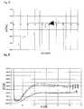
- FIG. 3shows the current / time curves (current I in amperes [A] against measurement time t in seconds [s]) for 7 blood coagulation measurements with 7 different sensors and in each case the same sample.
- FIG. 4shows the current / time curves (current I in amperes [A] against measurement time t in seconds [s]) for 3 blood coagulation measurements with 3 different sensors and the same sample in each case.
- FIG. 5shows a comparison of the so-called “failsafe admittance” (Ad2 / Ad1, y-axis) as a function of the contact resistance R (in ohms) between plug (in the measuring device) and electrode contact (on a test strip).
- FIG. 6shows the relative deviation of the clotting times ( ⁇ in%) as a function of the contact resistances R (in ohms) between plug (in the measuring device) and electrode contact (on a test strip).
- Example 1Construction of a typical electrochemical sensor
- FIG. 1shows schematically the electrode structures and the structure of an electrochemical sensor. Typical sensors of this type are also made WO 03/095092 and WO 2004/113917 known. FIG. 1 shows the structure of a typical electrochemical sensor in six subfigures (A to F).
- the electrochemical sensor 1consists of a base film 2, to which first the electrodes 3, 4, 5 are applied.
- the electrodes 3, 4, 5are printed, glued or produced by sputtering. It is also possible first to metallize the film 2 over the whole area (eg by sputtering or CVD) and then to work out the electrode structures by means of laser ablation or lithographic processes.
- the electrodes and printed conductorsmay consist of the same or different materials.
- the electrodes and tracksare made of a noble metal, such as. As gold, platinum, palladium or the like, or alloys or other inert materials.
- a reagent layer 6is applied to the electrodes 3, 4, 5 in the region in which the sample is to be recorded, for example by printing, dispensing, knife coating, slot die coating or the like, and dried.
- the reagent compositiondepends essentially on the analyte to be measured or the sample parameter to be determined and can be selected or produced accordingly by the person skilled in the art.
- a spacer (spacer) 7 made of a dielectric materialis applied to the base film 2, the electrodes 3, 4, 5 and the reagent layer 6.
- the spacer 7covers those parts of the electrodes which are not to come into contact with the sample and leaves free those parts of the electrodes which are to come into contact with the sample.
- ithas a recess 10 in the region of the reagent layer 6. This recess, together with the electrode structures in the reagent area, defines the actually active electrode area.
- the spacer 7also leaves areas of the electrodes / conductor tracks 3, 4, 5 exposed. These serve for contacting the sensor 1 in the measuring device (not shown).
- the sensor 1 shown in part Dwould in principle be suitable for carrying out measurements in liquid media.
- sample liquidcould be dropped from above onto the exposed area of the reagent layer 6.
- electrochemical sensorspreferably contain a capillary gap / capillary channel. This is produced by applying to the spacer 7 a further dielectric film (cover film 8). If the spacer is a few 100 microns or less thick so forms a capillary-active gap in the region of the recess 10. Sample can now be taken from the left side by capillary forces driven into the sensor 1. The thereby displaced air can escape through opening 9 from the gap.
- FIG. 1FThe completely assembled sensor 1 from FIG. 1E is shown in FIG. 1F in section along the line X-X '.
- An alternating voltage (8 mV, 10 kHz)is applied to the electrode set 1 from Example 1 for a period of 0.15 seconds and the conductivity is measured.
- the detected signalis referred to as admittance 1 (Ad1).
- an alternating voltage (8 mV, 10 kHz)is applied to the electrode set 2 from example 1 for a duration of 3 seconds and the conductivity is measured.
- the detected signalis referred to as admittance 2 (Ad2).
- admittance 1 and admittance 2are determined as so-called "failsafe admittance" signals.
- test strips measuring clotting times outside the 10% windowwill be detected as faulty because they produce "failsafe admittance" signals that are outside the “failsafe admittance” target range.
- the "failsafe admittance" signalsare, as described in Example 2, the quotients of two conductivity measurements (admittance 1 and admittance 2).
- the individual values of the representationare based on the above graph, are summarized in Table 1 by way of example for 5 samples.
- Table 1Comparison of admittance ratios for five exemplary test strips and the coagulation values measured with them strip Sample* Admittance A [10 -4 ] Review admittance Clotting time [s] Assessment clotting time A 1 A 2 A 2 / A 1 IS SHOULD rel.
- FIG. 3shows current / time curves as recorded in the measurement in an electrochemical coagulation sensor.
- a DC voltageis applied between two electrodes in the measuring chamber of the strip and the current is measured over time.
- test stripswere used in tests 1 to 3 and 5 to 7.
- a test stripwas used whose working electrode had too small an active area (for example, because the electrodes were contaminated with adhesive residue or because an air bubble was stuck over the electrodes in the capillary channel). Too low currents were measured for this test strip. This results in too long clotting times.
- test stripwhich had too small an active area of working electrode, was identified as defective by the parameter "Failsafe Admittance".
- Table 2Comparison of admittance ratios for 7 exemplary test strips and the coagulation values measured with them strip Admittance A [10 -4 ] Review admittance Clotting time [s] Assessment clotting time A 1 A 2 A 2 / A 1 IS SHOULD rel.
- Figure 4shows current / time curves generated as described in Example 3.
- Trial 3used a test strip whose working electrode had too large an active area, e.g. Under infiltration of a spacer, which determines the working electrode geometry, is observed with sample liquid. Too high currents were measured for this test strip. This results in too short clotting times.
- the test stripwhich had too large an active area of working electrode, is identified as defective by the Failsafe Admittance parameter.
- Table 3Comparison of admittance ratios for 3 exemplary test strips and the coagulation values measured with them strip
- Admittance A[10 -4 ]
- Review admittance Clotting time[s]
- the parameter "failsafe admittance" (Ad2 / Ad1) for various coagulation test strips of Example 2is compared with the contact resistances R (in ohms) measured between the plug (in the measuring device) and the electrode contact (on the test strip) with these test tires and the associated measuring devices ).
- Rcontact resistance
- FIG. 6shows the associated relative deviation of the coagulation times ⁇ (in%) as a function of the contact resistances R (in ohms) (analogous to FIG. 5).
- the permissible tolerance of the clotting time hereis ⁇ 10% (relative deviation) (solid horizontal lines).
- FIGS. 5 and 6Measurements associated with FIGS. 5 and 6 are shown by way of example in Table 4.
- R [ohm]Admittance A [10 -4 ] Review admittance Clotting time [s] Assessment clotting time A 1 A 2 A 2 / A 1 IS SHOULD rel.
- Example 6prove that the use of defective test strips or obsolete plugs in measuring instruments can be reliably excluded with the aid of the method according to the invention.
Landscapes
- Health & Medical Sciences (AREA)
- Chemical & Material Sciences (AREA)
- Hematology (AREA)
- Life Sciences & Earth Sciences (AREA)
- Electrochemistry (AREA)
- Chemical Kinetics & Catalysis (AREA)
- Molecular Biology (AREA)
- Physics & Mathematics (AREA)
- Analytical Chemistry (AREA)
- Biochemistry (AREA)
- General Health & Medical Sciences (AREA)
- General Physics & Mathematics (AREA)
- Immunology (AREA)
- Pathology (AREA)
- Investigating Or Analyzing Materials By The Use Of Electric Means (AREA)
Abstract
Translated fromGerman
Description
Translated fromGermanDie Erfindung betrifft ein Verfahren und ein entsprechendes System zum Überprüfen von elektrochemischen Sensoren mit zumindest zwei Elektroden.The invention relates to a method and a corresponding system for checking electrochemical sensors with at least two electrodes.
Die Erfindung betrifft insbesondere diagnostische Systeme zur Untersuchung von Körperflüssigkeiten wie Vollblut, Plasmen, Serum, Urin etc., die zur Aufnahme der zu untersuchenden Probe Testträger (wie Teststreifen, Kassetten, etc.) verwenden. Derartige Testträger haben üblicherweise eine Probenauftragsstelle und eine davon räumlich getrennte Messkammer. Der Aufbau der Testträger muss sicherstellen, dass der Transport der Probe von der Probenauftragsstelle zur Messkammer gewährleistet und letztere ausreichend mit Probenflüssigkeit gefüllt ist. Für diesen Flüssigkeitstransport können zum Beispiel Kapillaren benutzt werden, wie sie z. B. in
Die Messkammer beinhaltet in der Regel eine Detektionszone, die eine definierte Geometrie und eine definierte Fläche besitzt. Abweichungen in den Abmessungen führen zu Abweichungen im Messergebnis.As a rule, the measuring chamber contains a detection zone which has a defined geometry and a defined area. Deviations in the dimensions lead to deviations in the measurement result.
Bei der Herstellung der Testträger werden in der Regel Plastikmaterialien, wie Folien oder Spritzgussteile, verwendet, die eine kostengünstige Fertigung ermöglichen. Diese Plastikmaterialien müssen durch Klebe-, Schweiß- oder Spritzgussverfahren während der Fertigung miteinander verbunden werden.In the manufacture of the test carrier usually plastic materials, such as films or injection molded parts, are used, which allow a cost-effective production. These plastic materials must be bonded together by adhesive, welding or injection molding during manufacturing.
Dabei besteht die Gefahr, dass die Geometrie der Detektionszone in der Messkammer für einzelne Testträger von den Vorgaben abweicht. Diese Abweichungen können bei der Herstellung auftreten, zum Beispiel durch in die Messkammer bei der Fertigung austretenden Klebstoff oder von den Vorgaben abweichende Verschweiß- oder Verklebebedingungen. Es ist aber auch möglich, dass Testträger nach der Fertigung durch mechanische oder thermische Belastung verformt werden und sich dabei die Detektionsfläche in der Messkammer ändert. Außerdem ist es denkbar, dass die Elektrodenfläche selbst nicht in den vorgesehenen geometrischen Abmessungen gefertigt wurde oder durch nachträgliche Beschädigung verändert wurde.There is a risk that the geometry of the detection zone in the measuring chamber for individual test carrier deviates from the specifications. These deviations can occur during production, for example due to adhesive emerging into the measuring chamber during manufacture or welding or bonding conditions deviating from the specifications. However, it is also possible for test carriers to be deformed after production by mechanical or thermal stress and the detection surface in the measuring chamber changes as a result. In addition, it is conceivable that the electrode surface itself was not manufactured in the intended geometric dimensions or was changed by subsequent damage.
Schließlich kann durch unvollständige Befüllung mit Probenflüssigkeit, den Einschluss von Luftblasen in die Probenflüssigkeit oder undichte Messkammer die Detektionsfläche verändert werden.Finally, by incomplete filling with sample liquid, the inclusion of air bubbles in the sample liquid or leaking measuring chamber, the detection surface can be changed.
Nachteilig an diesem Verfahren ist, dass das eigentliche Messverfahren als Kontrolle herangezogen wird. Gerade bei langwierigen Messungen (z. B. im Bereich der Gerinnungsdiagnostik) vergeht so unter Umständen längere Zeit, bis feststeht, ob ein Sensor in Ordnung ist oder nicht. Fehler in Teilen des Messaufbaus, die für beide Sensorkanäle identisch sind (z. B. Kratzer in der Referenzelektrode o. ä.) werden nicht erkannt, da sie sich gleichermaßen auf beide Kanäle auswirken.A disadvantage of this method is that the actual measuring method is used as a control. Especially with lengthy measurements (eg in the area of coagulation diagnostics) it may take a long time to determine whether a sensor is in order or not. Errors in parts of the measurement setup that are identical for both sensor channels (eg scratches in the reference electrode or similar) are not detected because they affect both channels equally.
Das Verfahren gemäß
Im Stand der Technik mangelt es an Verfahren, mit deren Hilfe es möglich ist, die oben genannten Probleme zuverlässig zu erkennen und so Fehlmessungen zu vermeiden bzw. als solche zu kennzeichnen.In the prior art, there is a lack of methods by which it is possible to reliably detect the above-mentioned problems and thus to avoid faulty measurements or to identify them as such.
Aufgabe der vorliegenden Erfindung ist es, die Nachteile des Standes der Technik zu beseitigen. Insbesondere ist es die Aufgabe der vorliegenden Erfindung, ein Verfahren und ein System bereitzustellen, mit deren Hilfe fehlerhafte Elektroden bzw. Messbedingungen bei elektrochemischen Sensorsystemen zuverlässig erkannt werden können.The object of the present invention is to eliminate the disadvantages of the prior art. In particular, it is the object of the present invention to provide a method and a system by means of which faulty electrodes or measuring conditions can be reliably detected in electrochemical sensor systems.
Die Aufgabe wird durch den Gegenstand der Erfindung gelöst.The object is achieved by the subject matter of the invention.
Gegenstand der Erfindung ist ein Verfahren gemäß Anspruch 1 sowie ein dazugehöriges Messgerät gemäß Anspruch 8 bzw. Messsystem gemäß Anspruch 9. Vorteilhafte Ausgestaltungen der Erfindung sind Gegenstand der abhängigen Ansprüche.The invention relates to a method according to
Erster Gegenstand der Erfindung ist ein Verfahren zum Überprüfen der elektrochemisch aktiven Fläche von elektrochemischen Sensoren mit zumindest zwei Elektroden. Das Verfahren wird vorteilhaft dazu eingesetzt, Abweichungen der aktiven Elektrodenfläche der Sensorelektroden von vorgegebenen Werten festzustellen. Erfindungsgemäß wird hierzu zunächst dem Sensor ein flüssiges Messmedium zugeführt und ein erster Scheinleitwert (Admittanz) zwischen zwei Elektroden (die als erstes Elektrodenpaar bezeichnet werden sollen) bestimmt. Gleichzeitig oder nachfolgend wird ein zweiter Scheinleitwert zwischen zwei Elektroden (die als zweites Elektrodenpaar bezeichnet werden sollen) des Sensors bestimmt wird. Die zweiten zwei Elektroden können - je nach genauer Ausgestaltung des erfindungsgemäßen Verfahrens - identisch mit den ersten zwei Elektroden sein oder eine der zweiten Elektroden kann mit einer der ersten Elektroden identisch sein oder die zwei Elektrodenpaare haben keine gemeinsame Elektrode. Der erste und der zweite Scheinleitwert werden schließlich zueinander in Beziehung gesetzt. Vorzugsweise wird aus den beiden Scheinleitwerten ein Verhältnis gebildet, d. h. einer der Scheinleitwerte wird durch den anderen dividiert und das so erhaltene Verhältnis wird als Maß für die nachfolgende Bewertung herangezogen.The first object of the invention is a method for checking the electrochemically active surface of electrochemical sensors with at least two electrodes. The method is advantageously used to determine deviations of the active electrode area of the sensor electrodes from predetermined values. According to the invention, a liquid measuring medium is first supplied to the sensor for this purpose and a first admittance (admittance) between two electrodes (which are to be designated as the first pair of electrodes) is determined. Simultaneously or subsequently, a second admittance between two electrodes (which should be referred to as a second electrode pair) of the sensor is determined. The second two electrodes may be identical to the first two electrodes, depending on the precise configuration of the method according to the invention, or one of the second electrodes may be identical to one of the first electrodes or the two pairs of electrodes may not have a common electrode. The first and second admittances are finally related. Preferably, a ratio is formed from the two admittances, d. H. one of the admittances is divided by the other and the resulting ratio is used as a measure of the subsequent valuation.
Als flüssiges Messmedium kann eine Probenflüssigkeit, z. B. eine Körperflüssigkeit wie Blut, Serum, Plasma, Speichel, Schweiß etc., eine (wässrige) Umweltprobe, Prozessflüssigkeit, etc. oder eine (wässrige) Kontroll- bzw. Kalibrationsflüssigkeit verwendet werden.As a liquid measuring medium, a sample liquid, for. As a body fluid such as blood, serum, plasma, saliva, sweat, etc., an (aqueous) environmental sample, process fluid, etc., or an (aqueous) control or calibration fluid can be used.
Für das erfindungsgemäße Verfahren ist es prinzipiell unerheblich, welche Gestalt der zu messende Sensor hat. Der Sensor kann dabei jede beliebige, dem Fachmann an sich bekannte Gestalt aufweisen. Beispielsweise kann der Sensor einen freiliegenden, direkt mit dem Messmedium zu kontaktierenden Elektrodenbereich (analog dem Produkt AccuChek Advantage von Roche Diagnostics) oder einen Kapillarspalt/-kanal über dem Elektrodenbereich aufweisen (analog dem Produkt AccuChek Aviva oder AccuChek Comfort Curve von Roche Diagnostics). Es ist auch möglich, Sensoren für Durchflussmesszellen, die einen Probenkanal über dem Elektrodenbereich aufweisen (analog beispielsweise dem Produkt Roche Omni S von Roche Diagnostics) zu verwenden. Allen Sensoren ist jedoch gemeinsam, dass die elektrochemisch aktive Fläche der Elektroden des Sensors durch die Gestalt der Elektroden und ein Dielektrikum (z. B. in Form einer Abdeckung, eines Spacers oder eines Kanals) bestimmt wird. Die einzelnen Elektroden des Sensors können aus identischen oder unterschiedlichen Materialien gefertigt sein, wobei das Material als solches ebenfalls - im Rahmen dessen, was ein Fachmann auf dem Gebiet der elektrochemischen (Bio-)Sensoren verwenden würde - nicht erfindungswesentlich ist und beliebig gewählt werden kann.For the method according to the invention, it is fundamentally irrelevant which shape the sensor to be measured has. In this case, the sensor can have any shape known per se to the person skilled in the art. For example, the sensor may have an exposed electrode area to be directly contacted with the measuring medium (analogous to the product AccuChek Advantage from Roche Diagnostics) or a capillary gap / channel above the electrode area (analogous to the product AccuChek Aviva or AccuChek Comfort Curve from Roche Diagnostics). It is also possible to use sensors for flow cells which have a sample channel over the electrode area (analogous to, for example, the Roche Omni S product from Roche Diagnostics). However, all sensors have in common that the electrochemically active area of the electrodes of the sensor is determined by the shape of the electrodes and a dielectric (eg in the form of a cover, a spacer or a channel). The individual electrodes of the sensor can be off be made identical or different materials, the material as such also - within the scope of what would be used by a person skilled in the field of electrochemical (bio) sensors - is not essential to the invention and can be chosen arbitrarily.
Erfindungsgemäß wird zur Überprüfung der elektrochemischen Sensoren die Leitfähigkeit mittels Wechselstrom, d.h. der Scheinleitwert oder die Admittanz, ermittelt. Bevorzugt wird erfindungsgemäß die mittels hochfrequenter, niedervoltiger Wechselspannung ermittelte Admittanz verwendet. Als besonders bevorzugt hat sich eine Wechselspannungsfrequenz im Bereich einiger Kilohertz, ganz bevorzugt im Bereich von 10 kHz herausgestellt. Die Wechselspannung sollte vorzugsweise im bereich einiger mV, insbesondere bei 8 mV liegen.According to the invention, to check the electrochemical sensors, the conductivity is determined by means of alternating current, i. the admittance or admittance determined. According to the invention, the admittance determined by means of high-frequency, low-voltage AC voltage is preferably used. An AC frequency in the range of a few kilohertz, more preferably in the range of 10 kHz, has proven to be particularly preferred. The AC voltage should preferably be in the range of a few mV, in particular at 8 mV.
Vorzugsweise erfolgt beim erfindungsgemäßen Verfahren anschleißend an die Bewertung der Leitfähigkeitsmesswerte die Ausgabe des Ergebnisses der Überprüfung, insbesondere, wenn die Überprüfung ein von Sollzustand (Sollwert oder Sollbereich) abweichendes Resultat liefert. Typischerweise wird das Ergebnis mittels einer visuell erkennbaren Anzeigeeinheit (z. B. Lampe, Leuchtdiode, Display, über einen Drucker) angezeigt. Es ist jedoch auch möglich, im Falle einer Abweichung von Sollzustand ein akustisches Signal (z. B. über einen Summer oder Lautsprecher) oder ein fühlbares Signal (Vibrieren) auszugeben. Typischerweise wird hierbei zumindest eine Abweichung vom Sollzustand (d. h. eine Fehlermeldung) ausgegeben. Es ist jedoch auch möglich, ein Signal beim Erreichen des Sollzustands auszugeben. Außerdem ist es möglich, Messwerte, die mit Sensoren gemessen wurden, deren Prüfergebnisse außerhalb des Sollbereiches lagen, zu kennzeichnen, z. B. bei deren Anzeige, Ausdruck oder Speicherung. Man spricht davon, dass solche Werte entsprechend "geflagt" werden.In the method according to the invention, following the evaluation of the conductivity measured values, the output of the result of the check preferably takes place, in particular if the check delivers a result deviating from the setpoint state (desired value or setpoint range). Typically, the result is displayed by means of a visually recognizable display unit (eg, lamp, LED, display, via a printer). However, it is also possible to output an acoustic signal (eg via a buzzer or loudspeaker) or a tactile signal (vibration) in the event of a deviation from the nominal state. Typically, at least one deviation from the desired state (that is to say an error message) is output here. However, it is also possible to output a signal when the desired state is reached. In addition, it is possible to mark measured values which were measured with sensors whose test results were outside the nominal range, eg. B. in the display, expression or storage. It is said that such values are "flagged" accordingly.
Ein weiterer Gegenstand der Erfindung ist ein Messgerät, das zum Ausführen des erfindungsgemäßen Verfahrens geeignet ist. Das Messgerät enthält dabei zumindest eine Wechselspannungsquelle, Kontakte zum Anschluss von Elektroden eines Sensor, eine Steuer- und Messelektronik zum Erzeugen der Prüfspannungen und Erfassen der Sensorsignale, zumindest einen Prozessor zum Vergleichen und Inbeziehungsetzen der Sensorsignale anhand eines Programms zur Ausführung des erfindungsgemäßen Verfahrens und eine Ausgabeeinheit (Display, Datenschnittstelle, Druckeranschluss o. ä.).Another object of the invention is a measuring device which is suitable for carrying out the method according to the invention. In this case, the measuring device contains at least one AC voltage source, contacts for connecting electrodes of a sensor, control and measuring electronics for generating the test voltages and detecting the sensor signals, at least one processor for comparing and relating the sensor signals using a program for carrying out the method according to the invention and an output unit (Display, data interface, printer connection or similar).
Schließlich ist Gegenstand der Erfindung ein System zum Ausführen des erfindungsgemäßen Verfahrens enthaltend zumindest einen elektrochemischen Sensor mit mindestens 2 Elektroden sowie ein Messgerät gemäß des o. g. Gegenstands der Erfindung.Finally, the invention relates to a system for carrying out the method according to the invention comprising at least one electrochemical sensor with at least 2 electrodes and a measuring device according to the above-mentioned subject matter of the invention.
Die vorliegende Erfindung beschreibt unter anderem eine Methode, die die Feststellung von Abweichungen in der Fläche der Detektionszone ermöglicht und damit die Erhebung von fehlerhaften Messwerten aus den beschriebenen Gründen verhindert.Among other things, the present invention describes a method which enables the detection of deviations in the area of the detection zone and thus prevents the collection of erroneous measured values for the reasons described.
Die erfindungsgemäße Lösung des oben beschriebenen Problems basiert vorzugsweise auf der Integration von 2 Sets Elektroden in die Messkammer eines elektrochemischen Sensors. Jedes Set von Elektroden besteht aus 2 Elektroden. Dabei kann eine Elektrode Bestandteil von beiden Sets sein.The solution according to the invention of the problem described above is preferably based on the integration of 2 sets of electrodes into the measuring chamber of an electrochemical sensor. Each set of electrodes consists of 2 electrodes. An electrode can be part of both sets.
Zwischen den 2 Elektroden eines Sets wird, nach der Befüllung der Messkammer mit einem Messmedium, v. a. einer Probenflüssigkeit, eine Wechselspannung angelegt und die Leitfähigkeit (Scheinleitwert, Admittanz) über die Probe gemessen. Dabei wird zuerst die Leitfähigkeit zwischen einem Elektrodenpaar und danach, also zeitlich versetzt, die Leitfähigkeit zwischen dem zweiten Elektrodenpaar gemessen.Between the 2 electrodes of a set, after the filling of the measuring chamber with a measuring medium, v. a. a sample liquid, an AC voltage applied and the conductivity (admittance, admittance) measured over the sample. First, the conductivity between a pair of electrodes and then, that is offset in time, the conductivity between the second electrode pair is measured.
Die Elektroden sind so ausgelegt, dass eine Veränderung der Geometrie der Messkammer oder der Elektrodengeometrie die Größe der vom Messmedium benetzten Elektrodenfläche und damit die Höhe der gemessenen Leitfähigkeit verändert. Da die Leitfähigkeit nicht nur von der Geometrie der Elektroden, sondern auch von der Ionenkonzentration des Messmediums, der Temperatur etc. abhängt, ist eine Bewertung der Messkammergüte durch die Auswertung der gemessenen absoluten Leitfähigkeitswerte schwierig. Bildet man jedoch das Verhältnis der Leitfähigkeiten, die mit beiden Sets von Elektroden gemessen wurden, so ist eine Normierung auf die geometrischen Parameter möglich.The electrodes are designed so that a change in the geometry of the measuring chamber or the electrode geometry changes the size of the wetted by the measuring medium electrode surface and thus the height of the measured conductivity. Since the conductivity depends not only on the geometry of the electrodes, but also on the ion concentration of the measuring medium, the temperature, etc., an evaluation of the measuring chamber quality by the evaluation of the measured absolute conductivity values is difficult. However, if one measures the ratio of the conductivities measured with both sets of electrodes, normalization to the geometric parameters is possible.
Durch den Einbau einer Wartezeit zwischen den beiden Messungen kann man auch Veränderungen der benetzten Fläche detektieren. Werden die Elektrodenflächen zum Beispiel durch einen aufgeklebten Spacer begrenzt, ist bei nicht sachgerechter Verklebung eine Unterwanderung des Spacers durch Probenflüssigkeit möglich. Durch Messung der Leitfähigkeit zu unterschiedlichen Zeiten kann man diese, in der Regel langsame, Vergrößerung der benetzten Elektrodenfläche messen. In diesem Fall können Elektroden-Set 1 und Elektroden-Set 2 im Sinne dieser Erfindung identisch sein.By installing a waiting time between the two measurements, it is also possible to detect changes in the wetted area. If the electrode surfaces are delimited, for example, by a glued-on spacer, submerging of the spacer by sample liquid is possible if the bonding is not appropriate. By measuring the conductivity at different times, it is possible to measure this, generally slow, enlargement of the wetted electrode surface. In this case, electrode set 1 and electrode set 2 may be identical in the sense of this invention.
Das erfindungsgemäße Verfahren ermöglicht es zudem, zuverlässig die Verwendung gealterter oder beschädigter Systemkomponenten zu verhindern. Beispielsweise werden so genannte "parasitäre Widerstände" (engl.: parasitic contact resistance) erfasst, die durch Übergangswiderstände zwischen Teststreifen und Stecker im Messgerät entstehen, wenn z. B. die Kontakte gealtert oder die Streifen verkratzt sind.The inventive method also makes it possible to reliably prevent the use of aged or damaged system components. For example, so-called "parasitic resistances" (English: parasitic contact resistance) are detected, caused by contact resistance between the test strip and plug in the meter when z. B. the contacts aged or the stripes are scratched.
Die Erfindung wird anhand der nachfolgenden Beispiele und Figuren näher erläutert. Obwohl die Beispiele die Erfindung lediglich anhand von Gerinnungssensoren erläutern, kann das erfindungsgemäße Prinzip auf jegliche Art von elektrochemischen Sensoren, beispielsweise Enzymsensoren zur Bestimmung von Metaboliten wie Glukose oder Laktat aus Blutproben, ohne weiteres übertragen werden.The invention will be explained in more detail with reference to the following examples and figures. Although the examples illustrate the invention merely by means of coagulation sensors, the principle according to the invention can easily be transferred to any type of electrochemical sensors, for example enzyme sensors for the determination of metabolites, such as glucose or lactate, from blood samples.
Gegenüber der Messung der Gleichspannungs-Leitfähigkeit (Leitwert) hat das erfindungsgemäße Verfahren und das dazugehörige System den Vorteil, dass das Signal unabhängig von einer elektrochemisch detektierbaren Spezies ist, die Mechanismen und Systemkomponenten für eine Hämatokritbestimmung, die ebenfalls auf der Basis der Wechselspannungsleitfähigkeit beruht, mit überprüft werden und so genannte "parasitäre Widerstände" erfasst werden können.Compared to the measurement of the DC conductivity (conductivity), the method and the associated system according to the invention has the advantage that the signal is independent of an electrochemically detectable species, the mechanisms and system components for a hematocrit determination, which is also based on the Wechselspannungsleitfähigkeit with be checked and so-called "parasitic resistances" can be detected.
Figur 1 zeigt eine typische Ausführungsform der Elektrodenstrukturen und des Aufbaus eines elektrochemischen Sensors (Teststreifen), anhand dessen das erfindungsgemäße Verfahren erläutert werden kann.FIG. 1 shows a typical embodiment of the electrode structures and the structure of an electrochemical sensor (test strip), by means of which the method according to the invention can be explained.
Figur 2 zeigt grafisch den Zusammenhang zwischen der relativen Abweichung desFigure 2 shows graphically the relationship between the relative deviation of
Messergebnisses eines elektrochemischen Blutgerinnungssensors vom Sollwert (rel. Δ. in %; γ-Achse) aufgetragen gegen den Quotienten aus zwei Admittanz-Messungen (Ad2/Ad1; so genannte "Failsafe-Admittance"; x-Achse).Measurement result of an electrochemical blood coagulation sensor from the setpoint value (rel. Δ. In%, γ-axis) plotted against the quotient of two admittance measurements (Ad2 / Ad1, so-called "failsafe admittance", x-axis).
Figur 3 zeigt die Strom-/Zeitkurven (Strom I in Ampere [A] gegen Messzeit t in Sekunden [s]) für 7 Blutgerinnungsmessungen mit 7 unterschiedlichen Sensoren und jeweils der selben Probe.FIG. 3 shows the current / time curves (current I in amperes [A] against measurement time t in seconds [s]) for 7 blood coagulation measurements with 7 different sensors and in each case the same sample.
Figur 4 zeigt die Strom-/Zeitkurven (Strom I in Ampere [A] gegen Messzeit t in Sekunden [s]) für 3 Blutgerinnungsmessungen mit 3 unterschiedlichen Sensoren und jeweils der gleichen Probe.FIG. 4 shows the current / time curves (current I in amperes [A] against measurement time t in seconds [s]) for 3 blood coagulation measurements with 3 different sensors and the same sample in each case.
Figur 5 zeigt eine Gegenüberstellung der sog. "Failsafe-Admittance" (Ad2/Ad1, y-Achse) in Abhängigkeit vom Übergangswiderstand R (in Ohm) zwischen Stecker (im Messgerät) und Elektrodenkontakt (auf einem Teststreifen).FIG. 5 shows a comparison of the so-called "failsafe admittance" (Ad2 / Ad1, y-axis) as a function of the contact resistance R (in ohms) between plug (in the measuring device) and electrode contact (on a test strip).
Figur 6 zeigt die relative Abweichung der Gerinnungszeiten (Δ in %) in Abhängigkeit von den Übergangswiderständen R (in Ohm) zwischen Stecker (im Messgerät) und Elektrodenkontakt (auf einem Teststreifen).FIG. 6 shows the relative deviation of the clotting times (Δ in%) as a function of the contact resistances R (in ohms) between plug (in the measuring device) and electrode contact (on a test strip).
Die Ziffern und Abkürzungen in den Figuren bedeuten:
- 1
- Elektrochemischer Sensor
- 2
- Basisfolie
- 3
- 1. Elektrode
- 4
- 2. Elektrode
- 5
- 3. Elektrode
- 6
- Reagenzschicht
- 7
- Abstandhalter (Spacer)
- 8
- Deckelfolie
- 9
- Entlüftungsöffnung
- 10
- Aussparung
- Ad1
Admittanz 1- Ad2
Admittanz 2- Δ
- Relative Abweichung der gemessenen Gerinnungszeit vom Sollwert (in %)
- I
- Strom (in Ampere A)
- R
- Übergangswiderstand (in Ohm)
- t
- Messzeit (in Sekunden s)
- A
- Ampere
- s
- Sekunde(n)
- 1
- Electrochemical sensor
- 2
- base film
- 3
- 1st electrode
- 4
- 2nd electrode
- 5
- 3rd electrode
- 6
- reagent
- 7
- Spacer
- 8th
- cover film
- 9
- vent
- 10
- recess
- Ad1
Admittance 1- Ad2
Admittance 2- Δ
- Relative deviation of the measured clotting time from the nominal value (in%)
- I
- Current (in ampere A)
- R
- Contact resistance (in ohms)
- t
- Measuring time (in seconds s)
- A
- amp
- s
- Second (s)
Figur 1 zeigt schematisch die Elektrodenstrukturen und den Aufbau eines elektrochemischen Sensors. Typische Sensoren solcher Art sind auch aus
Der elektrochemische Sensor 1 besteht aus einer Basisfolie 2, auf die zunächst die Elektroden 3, 4, 5 aufgebracht werden. Typischerweise werden die Elektroden 3, 4, 5 gedruckt, aufgeklebt oder durch Sputtern erzeugt. Es ist auch möglich, die Folie 2 zunächst vollflächig zu metallisieren (z. B. durch Sputtern oder CVD) und anschließend die Elektrodenstrukturen mittels Laserablation oder lithographischer Verfahren herauszuarbeiten. Die Elektroden und Leiterbahnen können aus den gleichen oder unterschiedlichen Materialien bestehen.The
Typischerweise bestehen die Elektroden und Leiterbahnen aus einem Edelmetall, wie z. B. Gold, Platin, Palladium o. ä., oder Legierungen oder anderen inerten Materialien.Typically, the electrodes and tracks are made of a noble metal, such as. As gold, platinum, palladium or the like, or alloys or other inert materials.
Auf die Elektroden 3, 4, 5 wird in dem Bereich, in dem die Probe aufgenommen werden soll, eine Reagenzschicht 6 aufgebracht, beispielsweise durch Drucken, Dispensieren, Aufrakeln, Schlitzdüsenbeschichtung o. ä., und getrocknet. Die Reagenzzusammensetzung richtet sich im Wesentlichen nach dem zu messenden Analyten bzw. zu bestimmenden Probenparameter und kann vom Fachmann entsprechend ausgesucht bzw. hergestellt werden.A
Nach dem Trocknen der Reagenzschicht wird auf die Basisfolie 2, die Elektroden 3, 4, 5 und die Reagenzschicht 6 ein Abstandhalter (Spacer) 7 aufgebracht, der aus einem dielektrischen Material besteht. Der Spacer 7 bedeckt dabei diejenigen Teile der Elektroden, die nicht mit Probe in Kontakt kommen sollen, und lässt diejenigen Teile der Elektroden frei, die mit Probe in Kontakt kommen sollen. Hierfür weist er im Bereich der Reagenzschicht 6 eine Aussparung 10 auf. Diese Aussparung definiert zusammen mit den Elektrodenstrukturen im Reagenzbereich die tatsächlich aktive Elektrodenfläche.After drying the reagent layer, a spacer (spacer) 7 made of a dielectric material is applied to the
Am der Reagenzschicht 6 gegenüberliegenden Ende des Sensors 1 lässt der Spacer 7 ebenfalls Bereiche der Elektroden/Leiterbahnen 3, 4, 5 frei. Diese dienen der Kontaktierung des Sensors 1 im Messgerät (nicht gezeigt).At the end of the
Der in Teilfigur D gezeigte Sensor 1 wäre im Prinzip dazu geeignet, Messungen in flüssigen Medien durchzuführen. Beispielsweise könnte Probenflüssigkeit von oben auf den freiliegenden Bereich der Reagenzschicht 6 aufgetropft werden.The
Vorzugsweise enthalten elektrochemische Sensoren aus Gründen der Hygiene und der einfachen Probendosierung einen Kapillarspalt/Kapillarkanal. Dieser wird dadurch erzeugt, dass auf den Spacer 7 eine weitere dielektrische Folie (Deckelfolie 8) aufgebracht wird. Falls der Spacer wenige 100 µm oder weniger dick ist bildet sich so ein kapillaraktiver Spalt im Bereich der Aussparung 10. Probe kann nun von der linken Seite her durch Kapillarkräfte getrieben in den Sensor 1 aufgenommen werden. Die dabei verdrängte Luft kann über Öffnung 9 aus dem Spalt entweichen.For reasons of hygiene and simple sample dosing, electrochemical sensors preferably contain a capillary gap / capillary channel. This is produced by applying to the spacer 7 a further dielectric film (cover film 8). If the spacer is a few 100 microns or less thick so forms a capillary-active gap in the region of the
Der komplett montierte Sensor 1 aus Figur 1E ist in Figur 1F im Schnitt entlang der Linie X-X' dargestellt.The completely assembled
Die zwei Sets von Elektroden, die in den nachfolgenden Beispielen für das erfindungsgemäße Verfahren verwendet wurden, setzen sich wie folgt zusammen:
- Set1: 1.
Elektrode 3/2.Elektrode 4 - Set 2: 2.
Elektrode 4 /3.Elektrode 5
- Set1:
1st electrode 3/2.Electrode 4 - Set 2:
2nd electrode 4/3.Electrode 5
Wie bereits oben dargelegt, reicht es - je nach Anwendung - wenn 2 Elektroden in zeitlichem Abstand vermessen werden. So lässt sich mit nur 2 Elektroden erkennen, ob Probenflüssigkeit unter den Spacer 7 wandert. Andererseits ist es auch möglich, die Signale von mehr als 3 Elektroden heranzuziehen, z. B. also je Elektrodenset 2 individuelle, unterschiedliche Elektroden zu benutzen.As already stated above, it is sufficient - depending on the application - if 2 electrodes are measured at a time interval. Thus it can be detected with only 2 electrodes whether sample liquid migrates under the
An das Elektroden-Set 1 aus Beispiel 1 wird für eine Dauer von 0,15 Sekunden eine Wechselspannung (8 mV; 10 kHz) angelegt und die Leitfähigkeit gemessen. Das ermittelte Signal wird als Admittanz 1 (Ad1) bezeichnet.An alternating voltage (8 mV, 10 kHz) is applied to the electrode set 1 from Example 1 for a period of 0.15 seconds and the conductivity is measured. The detected signal is referred to as admittance 1 (Ad1).
Nach einer Wartezeit von 1 Sekunde wird an das Elektroden-Set 2 aus Beispiel 1 für eine Dauer von 3 Sekunden eine Wechselspannung (8 mV; 10 kHz) angelegt und die Leitfähigkeit gemessen. Das ermittelte Signal wird als Admittanz 2 (Ad2) bezeichnet.After a waiting time of 1 second, an alternating voltage (8 mV, 10 kHz) is applied to the electrode set 2 from example 1 for a duration of 3 seconds and the conductivity is measured. The detected signal is referred to as admittance 2 (Ad2).
Als so genannte "Failsafe-Admittance"-Signale werden die Quotienten aus Admittanz 1 und Admittanz 2 (Ad2/Ad1) bestimmt.The quotients of
In Figur 2 ist der Parameter "Failsafe-Admittance" (Ad2/Ad1) für diverse Gerinnungsteststreifen des Beispiels 2 gegen die mit diesen Teststreifen gemessene Gerinnungszeit aufgetragen.In FIG. 2, the parameter "failsafe admittance" (Ad2 / Ad1) for various coagulation test strips of example 2 is plotted against the coagulation time measured with these test strips.
Für die "Failsafe-Admittance" wurde ein "Sollbereich" definiert (senkrechte durchgezogene Linien). Alle Teststreifen, deren "Failsafe-Admittance" innerhalb des Sollbereichs liegen, zeigen Gerinnungswerte in einem sehr engen Fenster (+/- 10 %; waagerechte durchgezogene Linien) um den Chargenmittelwert.For the "failsafe admittance" a "target range" was defined (vertical solid lines). All test strips whose failsafe admittance is within the target range show coagulation values in a very narrow window (+/- 10%, horizontal solid lines) around the batch mean.
Alle Teststreifen, mit denen Gerinnungszeiten außerhalb des 10%-Fensters gemessen werden, werden als fehlerhaft erkannt, weil sie "Failsafe-Admittance"-Signale erzeugen, die außerhalb des "Failsafe-Admittance"-Sollbereichs liegen.Any test strips measuring clotting times outside the 10% window will be detected as faulty because they produce "failsafe admittance" signals that are outside the "failsafe admittance" target range.
Die "Failsafe-Admittance"-Signale sind, wie in Beispiel 2 beschrieben, die Quotienten aus zwei Leitfähigkeitsmessungen (Admittanz 1 und Admittanz 2). Die Einzelwerte die der Darstellung in obiger Graphik zugrunde liegen, sind in Tabelle 1 exemplarisch für 5 Proben zusammengestellt.
Figur 3 zeigt Strom- / Zeitkurven, wie sie bei der Messung in einem elektrochemischen Gerinnungssensor aufgenommen werden. Dafür werden zwischen zwei Elektroden in der Messkammer des Streifen eine Gleichspannung angelegt und der Strom über die Zeit gemessen.FIG. 3 shows current / time curves as recorded in the measurement in an electrochemical coagulation sensor. For this purpose, a DC voltage is applied between two electrodes in the measuring chamber of the strip and the current is measured over time.
In den Versuchen 1 bis 3 und 5 bis 7 wurden intakte Teststreifen eingesetzt. In Versuch 4 wurde ein Teststreifen verwendet, dessen Arbeitelektrode eine zu kleine aktive Fläche (beispielsweise, weil die Elektroden mit Kleberresten verunreinigt waren oder, weil eine Luftblase über den Elektroden im Kapillarkanal festsaß) besaß. Für diesen Teststreifen wurden zu niedrige Ströme gemessen. Das resultiert in zu langen Gerinnungszeiten.In
Wie Tabelle 2 zeigt, wird der Teststreifen, der eine zu kleine aktive Fläche an Arbeitselektrode aufwies, durch den Parameter "Failsafe Admittance" als fehlerhaft erkannt.
Figur 4 zeigt Strom- / Zeitkurven, die wie in Beispiel 3 beschrieben erzeugt wurden.Figure 4 shows current / time curves generated as described in Example 3.
In den Versuchen 1 und 2 wurden intakte Teststreifen eingesetzt. In Versuch 3 wurde ein Teststreifen verwendet, dessen Arbeitelektrode eine zu große aktive Fläche besaß, wie es z.B. bei Unterwanderung eines Spacers, der die Arbeitselektrodengeometrie bestimmt, mit Probenflüssigkeit zu beobachten ist. Für diesen Teststreifen wurden zu hohe Ströme gemessen. Das resultiert in zu kurzen Gerinnungszeiten.In
Wie Tabelle 3 zeigt, wird der Teststreifen, der eine zu große aktive Fläche an Arbeitselektrode aufwies, durch den Parameter "Failsafe Admittance" als fehlerhaft erkannt.
"Parasitäre Widerstände" (engl.: parasitic contact resistance), beispielsweise verursacht durch Übergangswiderstände zwischen Streifen und Stecker (Altern der Kontakte, Kratzer am Streifen), können über das erfindungsgemäße Verfahren erfasst und Fehlmessungen somit zuverlässig verhindert werden. Die Figuren 5 und 6 sowie Tabelle 4 belegen dies."Parasitic resistances" (English: parasitic contact resistance), for example, caused by contact resistances between strip and plug (aging of the contacts, scratches on the strip) can be detected by the inventive method and thus erroneous measurements can be reliably prevented. Figures 5 and 6 and Table 4 prove this.
In Figur 5 ist der Parameter "Failsafe-Admittance" (Ad2/Ad1) für diverse Gerinnungsteststreifen des Beispiels 2 gegen die mit diesen Testsreifen und den dazugehörigen Messgeräten gemessenen Übergangswiderständen R (in Ohm) zwischen Stecker (im Messgerät) und Elektrodenkontakt (auf dem Teststreifen) dargestellt. Für die "Failsafe-Admittance" wurde ein "Sollbereich" definiert (waagrechte durchgezogene Linien).In FIG. 5, the parameter "failsafe admittance" (Ad2 / Ad1) for various coagulation test strips of Example 2 is compared with the contact resistances R (in ohms) measured between the plug (in the measuring device) and the electrode contact (on the test strip) with these test tires and the associated measuring devices ). For the "failsafe admittance" a "target range" was defined (horizontal solid lines).
Figur 6 zeigt die dazugehörige relative Abweichung der Gerinnungszeiten Δ (in %) in Abhängigkeit von den Übergangswiderständen R (in Ohm) (analog Figur 5). Die zulässige Toleranz der Gerinnungszeit beträgt hier ± 10 % (relative Abweichung) (durchgezogene waagrechte Linien).FIG. 6 shows the associated relative deviation of the coagulation times Δ (in%) as a function of the contact resistances R (in ohms) (analogous to FIG. 5). The permissible tolerance of the clotting time here is ± 10% (relative deviation) (solid horizontal lines).
Zu Figur 5 und 6 gehörige Messwerte sind exemplarisch in Tabelle 4 wiedergegeben.
Die Daten von Beispiel 6 belegen, dass mit Hilfe des erfindungsgemäßen Verfahrens zuverlässig die Verwendung von schadhaften Teststreifen bzw. veralteten Steckern in Messgeräten ausgeschlossen werden kann.The data of Example 6 prove that the use of defective test strips or obsolete plugs in measuring instruments can be reliably excluded with the aid of the method according to the invention.
Claims (9)
Translated fromGermanwobei die zwei Elektroden in Schritt ii) identisch mit den zwei Elektroden in Schritt iii) sein können oder eine der Elektroden in Schritt ii) mit einer der Elektroden in Schritt iii) identisch sein kann oder keine der Elektroden in Schritt ii) mit Elektroden in Schritt iii) identisch sein kann; und
wherein the two electrodes in step ii) may be identical to the two electrodes in step iii), or one of the electrodes in step ii) may be identical to one of the electrodes in step iii) or none of the electrodes in step ii) with electrodes in step iii) can be identical; and
Priority Applications (1)
| Application Number | Priority Date | Filing Date | Title |
|---|---|---|---|
| EP06020924.4AEP1772728B1 (en) | 2005-10-05 | 2006-10-05 | Method and system for testing electrochemical sensors |
Applications Claiming Priority (2)
| Application Number | Priority Date | Filing Date | Title |
|---|---|---|---|
| EP05021853 | 2005-10-05 | ||
| EP06020924.4AEP1772728B1 (en) | 2005-10-05 | 2006-10-05 | Method and system for testing electrochemical sensors |
Publications (2)
| Publication Number | Publication Date |
|---|---|
| EP1772728A1true EP1772728A1 (en) | 2007-04-11 |
| EP1772728B1 EP1772728B1 (en) | 2014-01-15 |
Family
ID=35601858
Family Applications (1)
| Application Number | Title | Priority Date | Filing Date |
|---|---|---|---|
| EP06020924.4AActiveEP1772728B1 (en) | 2005-10-05 | 2006-10-05 | Method and system for testing electrochemical sensors |
Country Status (3)
| Country | Link |
|---|---|
| US (2) | US7429865B2 (en) |
| EP (1) | EP1772728B1 (en) |
| ES (1) | ES2446518T3 (en) |
Families Citing this family (31)
| Publication number | Priority date | Publication date | Assignee | Title |
|---|---|---|---|---|
| US8148164B2 (en) | 2003-06-20 | 2012-04-03 | Roche Diagnostics Operations, Inc. | System and method for determining the concentration of an analyte in a sample fluid |
| US7488601B2 (en)* | 2003-06-20 | 2009-02-10 | Roche Diagnostic Operations, Inc. | System and method for determining an abused sensor during analyte measurement |
| US7452457B2 (en) | 2003-06-20 | 2008-11-18 | Roche Diagnostics Operations, Inc. | System and method for analyte measurement using dose sufficiency electrodes |
| US7718439B2 (en)* | 2003-06-20 | 2010-05-18 | Roche Diagnostics Operations, Inc. | System and method for coding information on a biosensor test strip |
| US8529751B2 (en) | 2006-03-31 | 2013-09-10 | Lifescan, Inc. | Systems and methods for discriminating control solution from a physiological sample |
| US20100021940A1 (en)* | 2006-04-12 | 2010-01-28 | Astrazeneca Ab | Method for Determining the Activity of a Protease in a Sample |
| US7550979B2 (en)* | 2007-05-29 | 2009-06-23 | Georg Fischer Signet Llc | System and method for measuring conductivity of fluid |
| US8778168B2 (en)* | 2007-09-28 | 2014-07-15 | Lifescan, Inc. | Systems and methods of discriminating control solution from a physiological sample |
| US8603768B2 (en) | 2008-01-17 | 2013-12-10 | Lifescan, Inc. | System and method for measuring an analyte in a sample |
| US8097146B2 (en) | 2008-03-27 | 2012-01-17 | Sensor Electronics Corporation | Device and method for monitoring an electrochemical gas sensor |
| US8344733B2 (en)* | 2008-03-27 | 2013-01-01 | Panasonic Corporation | Sample measurement device, sample measurement system and sample measurement method |
| US8551320B2 (en)* | 2008-06-09 | 2013-10-08 | Lifescan, Inc. | System and method for measuring an analyte in a sample |
| IL209760A (en) | 2009-12-11 | 2015-05-31 | Lifescan Scotland Ltd | Fill sufficiency method and system |
| DE102012106384B4 (en)* | 2012-07-16 | 2016-05-25 | Endress + Hauser Conducta Gesellschaft für Mess- und Regeltechnik mbH + Co. KG | Method for determining at least one malfunction of a conductive conductivity sensor |
| CN105190299B (en) | 2013-03-15 | 2018-04-20 | 豪夫迈·罗氏有限公司 | The method based on descriptor of electrochemical measurement analyte and the unit and system with reference to this method |
| CA2949906C (en)* | 2013-03-15 | 2019-04-02 | F. Hoffmann-La Roche Ag | Methods of scaling data used to construct biosensor algorithms as well as devices, apparatuses and systems incorporating the same |
| CA2900885C (en) | 2013-03-15 | 2017-12-19 | F. Hoffmann-La Roche Ag | Methods of electrochemically measuring an analyte with a test sequence having a pulsed dc block as well as devices, apparatuses and systems incorporating the same |
| CN105247356B (en) | 2013-03-15 | 2017-11-07 | 豪夫迈·罗氏有限公司 | Methods of using information from recovery pulses in electrochemical analyte measurements and devices, devices and systems incorporating said methods |
| KR101743382B1 (en) | 2013-03-15 | 2017-06-02 | 에프. 호프만-라 로슈 아게 | Methods of detecting high antioxidant levels during electrochemical measurements and failsafing an analyte concentration therefrom as well as devices, apparatuses and systems incorporting the same |
| KR101732300B1 (en) | 2013-03-15 | 2017-05-02 | 에프. 호프만-라 로슈 아게 | Methods of failsafing electrochemical measurements of an analyte as well as devices, apparatuses and systems incorporating the same |
| CN103412012B (en) | 2013-03-28 | 2015-09-09 | 利多(香港)有限公司 | biological sensor |
| KR20160009619A (en) | 2013-06-10 | 2016-01-26 | 에프. 호프만-라 로슈 아게 | Method and system for detecting an analyte in a body fluid |
| US20150176049A1 (en) | 2013-12-23 | 2015-06-25 | Cilag Gmbh International | Determining usability of analytical test strip |
| EP3216076B1 (en) | 2014-11-03 | 2024-03-06 | F. Hoffmann-La Roche AG | Method of using electrochemical test elements having multiple electrode arrangements |
| US10378098B2 (en) | 2015-03-18 | 2019-08-13 | Materion Corporation | Methods for optimized production of multilayer metal/transparent conducting oxide (TCO) constructs |
| US10197522B2 (en) | 2015-03-18 | 2019-02-05 | Materion Corporation | Multilayer constructs for metabolite strips providing inert surface and mechanical advantage |
| WO2018067235A1 (en) | 2016-10-05 | 2018-04-12 | Roche Diabetes Care, Inc. | Detection reagents and electrode arrangements for multi-analyte diagnostic test elements, as well as methods of using the same |
| WO2018080637A1 (en) | 2016-10-24 | 2018-05-03 | Roche Diabetes Care, Inc. | Methods of correcting for uncompensated resistances in the conductive elements of biosensors, as well as devices and systems |
| CA3061348C (en)* | 2017-06-08 | 2023-02-14 | F. Hoffmann-La Roche Ag | Electrode break detection |
| EP3969890A4 (en)* | 2019-05-17 | 2023-06-07 | University of Ottawa | DEVICES AND METHODS FOR THE SELECTIVE DETECTION OF CANNABINOIDS |
| WO2025025107A1 (en)* | 2023-07-31 | 2025-02-06 | 深圳市理邦精密仪器股份有限公司 | Sample test card, testing assembly, and medical testing device |
Citations (11)
| Publication number | Priority date | Publication date | Assignee | Title |
|---|---|---|---|---|
| US4822456A (en)* | 1987-06-05 | 1989-04-18 | Bryan Avron I | Ion measuring apparatus and monitoring system |
| WO1993008477A1 (en)* | 1991-10-25 | 1993-04-29 | Rosemount Analytical Inc. | SELF DIAGNOSTIC pH SENSOR |
| US5352351A (en) | 1993-06-08 | 1994-10-04 | Boehringer Mannheim Corporation | Biosensing meter with fail/safe procedures to prevent erroneous indications |
| US6088608A (en)* | 1997-10-20 | 2000-07-11 | Alfred E. Mann Foundation | Electrochemical sensor and integrity tests therefor |
| WO2001075438A2 (en)* | 2000-03-31 | 2001-10-11 | Lifescan, Inc. | Electrically-conductive patterns for monitoring the filling of medical devices |
| WO2003095092A1 (en) | 2002-05-07 | 2003-11-20 | Roche Diagnostics Gmbh | Sampling device for liquid samples |
| US6733655B1 (en) | 2000-03-08 | 2004-05-11 | Oliver W. H. Davies | Measurement of substances in liquids |
| EP1443322A1 (en)* | 2001-10-12 | 2004-08-04 | ARKRAY, Inc. | Concentration measuring method and concentration measuring device |
| EP1455182A1 (en)* | 2001-11-20 | 2004-09-08 | Arkray Inc. | Fail judging method and analyzer |
| WO2004113917A2 (en) | 2003-06-20 | 2004-12-29 | Roche Diagnostics Gmbh | Method and reagent for producing narrow, homogenous reagent strips |
| WO2005078437A1 (en)* | 2004-02-06 | 2005-08-25 | Bayer Healthcare Llc | Electrochemical biosensor |
Family Cites Families (6)
| Publication number | Priority date | Publication date | Assignee | Title |
|---|---|---|---|---|
| US5223796A (en)* | 1991-05-28 | 1993-06-29 | Axiomatics Corporation | Apparatus and methods for measuring the dielectric and geometric properties of materials |
| US6790178B1 (en)* | 1999-09-24 | 2004-09-14 | Healthetech, Inc. | Physiological monitor and associated computation, display and communication unit |
| US6377655B1 (en)* | 1998-05-08 | 2002-04-23 | Nikon Corporation | Reflective mirror for soft x-ray exposure apparatus |
| US6721080B1 (en)* | 2002-09-27 | 2004-04-13 | D Morgan Tench | Optimum switching of a reversible electrochemical mirror device |
| US7253644B2 (en)* | 2004-06-01 | 2007-08-07 | Exxonmobil Research And Engineering Company | Apparatus and method for measuring electrochemical and viscoelastic properties of a liquid |
| US7601299B2 (en)* | 2004-06-18 | 2009-10-13 | Roche Diagnostics Operations, Inc. | System and method for coding information on a biosensor test strip |
- 2006
- 2006-10-04USUS11/542,701patent/US7429865B2/enactiveActive
- 2006-10-05ESES06020924.4Tpatent/ES2446518T3/enactiveActive
- 2006-10-05EPEP06020924.4Apatent/EP1772728B1/enactiveActive
- 2008
- 2008-08-07USUS12/187,451patent/US7626401B2/enactiveActive
Patent Citations (11)
| Publication number | Priority date | Publication date | Assignee | Title |
|---|---|---|---|---|
| US4822456A (en)* | 1987-06-05 | 1989-04-18 | Bryan Avron I | Ion measuring apparatus and monitoring system |
| WO1993008477A1 (en)* | 1991-10-25 | 1993-04-29 | Rosemount Analytical Inc. | SELF DIAGNOSTIC pH SENSOR |
| US5352351A (en) | 1993-06-08 | 1994-10-04 | Boehringer Mannheim Corporation | Biosensing meter with fail/safe procedures to prevent erroneous indications |
| US6088608A (en)* | 1997-10-20 | 2000-07-11 | Alfred E. Mann Foundation | Electrochemical sensor and integrity tests therefor |
| US6733655B1 (en) | 2000-03-08 | 2004-05-11 | Oliver W. H. Davies | Measurement of substances in liquids |
| WO2001075438A2 (en)* | 2000-03-31 | 2001-10-11 | Lifescan, Inc. | Electrically-conductive patterns for monitoring the filling of medical devices |
| EP1443322A1 (en)* | 2001-10-12 | 2004-08-04 | ARKRAY, Inc. | Concentration measuring method and concentration measuring device |
| EP1455182A1 (en)* | 2001-11-20 | 2004-09-08 | Arkray Inc. | Fail judging method and analyzer |
| WO2003095092A1 (en) | 2002-05-07 | 2003-11-20 | Roche Diagnostics Gmbh | Sampling device for liquid samples |
| WO2004113917A2 (en) | 2003-06-20 | 2004-12-29 | Roche Diagnostics Gmbh | Method and reagent for producing narrow, homogenous reagent strips |
| WO2005078437A1 (en)* | 2004-02-06 | 2005-08-25 | Bayer Healthcare Llc | Electrochemical biosensor |
Also Published As
| Publication number | Publication date |
|---|---|
| US20090027064A1 (en) | 2009-01-29 |
| US7626401B2 (en) | 2009-12-01 |
| ES2446518T3 (en) | 2014-03-10 |
| EP1772728B1 (en) | 2014-01-15 |
| US20070102292A1 (en) | 2007-05-10 |
| US7429865B2 (en) | 2008-09-30 |
Similar Documents
| Publication | Publication Date | Title |
|---|---|---|
| EP1772728B1 (en) | Method and system for testing electrochemical sensors | |
| DE60122517T2 (en) | ELECTRICALLY CONDUCTIVE PATTERN FOR MONITORING THE FILLING OF MEDICAL DEVICES | |
| EP1394534B1 (en) | Flow measuring cell with an apparatus for checking positioning and freedom from bubbles of a medical microsample | |
| DE60114159T2 (en) | MEASUREMENT OF SUBSTANCES IN LIQUIDS | |
| DE69434438T2 (en) | BIOS SENSOR WITH FAILSAFE OPERATING PROCEDURE TO AVOID FALSE DISPLAYS | |
| DE69434042T2 (en) | PLUG-IN STORAGE BLOCK | |
| DE3202067C2 (en) | Device for determining the hematocrit value | |
| DE60224863T2 (en) | Electrochemical sensor with a means for detecting underfilling | |
| EP2199792B1 (en) | Method for testing the quality of the thermal coupling of a measuring cell | |
| EP1977225B1 (en) | Electrochemical biosensor analysis system | |
| DE202010016517U1 (en) | System for measuring analyte concentration with interfering substance correction | |
| DE69633431T2 (en) | Fluoroelastomer seal for a sensor of blood components | |
| DE102014116777A1 (en) | Microfluidic sensor | |
| MX2008012865A (en) | System and methods for providing corrected analyte concentration measurements. | |
| DE112018005405T5 (en) | CONTROL OF pH TO DETECT ANALYTES | |
| DE2224703A1 (en) | Electrochemical measuring device | |
| DE602004009665T2 (en) | SYSTEM AND METHOD FOR MEASURING A COAGULATION TIME WITHOUT THERMOSTATIC CONTROL | |
| DE202015101592U1 (en) | Electrochemical biosensing instrument and system for analyte measurement with sample fill detection | |
| DE69304922T2 (en) | SENSOR DEVICES | |
| EP1393807A1 (en) | Testing device for examining a biological sample | |
| DE60220288T2 (en) | Determining the accuracy of a sample volume in biosensors | |
| EP3315964B1 (en) | Method of measuring hematocrit and method of testing blood | |
| DE102006014825B4 (en) | Circuit arrangement and method for the voltametric signal processing of biosensors | |
| EP1632773B1 (en) | Method of detecting a gas bubble in an aqueous liquid | |
| US9151730B2 (en) | Method for determining the electrochemical characteristic of a test strip |
Legal Events
| Date | Code | Title | Description |
|---|---|---|---|
| PUAI | Public reference made under article 153(3) epc to a published international application that has entered the european phase | Free format text:ORIGINAL CODE: 0009012 | |
| AK | Designated contracting states | Kind code of ref document:A1 Designated state(s):AT BE BG CH CY CZ DE DK EE ES FI FR GB GR HU IE IS IT LI LT LU LV MC NL PL PT RO SE SI SK TR | |
| AX | Request for extension of the european patent | Extension state:AL BA HR MK YU | |
| 17P | Request for examination filed | Effective date:20071011 | |
| 17Q | First examination report despatched | Effective date:20071112 | |
| AKX | Designation fees paid | Designated state(s):AT BE BG CH CY CZ DE DK EE ES FI FR GB GR HU IE IS IT LI LT LU LV MC NL PL PT RO SE SI SK TR | |
| GRAP | Despatch of communication of intention to grant a patent | Free format text:ORIGINAL CODE: EPIDOSNIGR1 | |
| INTG | Intention to grant announced | Effective date:20130913 | |
| GRAS | Grant fee paid | Free format text:ORIGINAL CODE: EPIDOSNIGR3 | |
| GRAA | (expected) grant | Free format text:ORIGINAL CODE: 0009210 | |
| AK | Designated contracting states | Kind code of ref document:B1 Designated state(s):AT BE BG CH CY CZ DE DK EE ES FI FR GB GR HU IE IS IT LI LT LU LV MC NL PL PT RO SE SI SK TR | |
| REG | Reference to a national code | Ref country code:GB Ref legal event code:FG4D Free format text:NOT ENGLISH Ref country code:CH Ref legal event code:EP | |
| REG | Reference to a national code | Ref country code:AT Ref legal event code:REF Ref document number:650047 Country of ref document:AT Kind code of ref document:T Effective date:20140215 | |
| REG | Reference to a national code | Ref country code:IE Ref legal event code:FG4D Free format text:LANGUAGE OF EP DOCUMENT: GERMAN | |
| REG | Reference to a national code | Ref country code:DE Ref legal event code:R096 Ref document number:502006013503 Country of ref document:DE Effective date:20140227 | |
| REG | Reference to a national code | Ref country code:ES Ref legal event code:FG2A Ref document number:2446518 Country of ref document:ES Kind code of ref document:T3 Effective date:20140310 | |
| REG | Reference to a national code | Ref country code:NL Ref legal event code:T3 | |
| REG | Reference to a national code | Ref country code:LT Ref legal event code:MG4D | |
| PG25 | Lapsed in a contracting state [announced via postgrant information from national office to epo] | Ref country code:LT Free format text:LAPSE BECAUSE OF FAILURE TO SUBMIT A TRANSLATION OF THE DESCRIPTION OR TO PAY THE FEE WITHIN THE PRESCRIBED TIME-LIMIT Effective date:20140115 Ref country code:IS Free format text:LAPSE BECAUSE OF FAILURE TO SUBMIT A TRANSLATION OF THE DESCRIPTION OR TO PAY THE FEE WITHIN THE PRESCRIBED TIME-LIMIT Effective date:20140515 | |
| PG25 | Lapsed in a contracting state [announced via postgrant information from national office to epo] | Ref country code:CY Free format text:LAPSE BECAUSE OF FAILURE TO SUBMIT A TRANSLATION OF THE DESCRIPTION OR TO PAY THE FEE WITHIN THE PRESCRIBED TIME-LIMIT Effective date:20140115 Ref country code:SE Free format text:LAPSE BECAUSE OF FAILURE TO SUBMIT A TRANSLATION OF THE DESCRIPTION OR TO PAY THE FEE WITHIN THE PRESCRIBED TIME-LIMIT Effective date:20140115 Ref country code:FI Free format text:LAPSE BECAUSE OF FAILURE TO SUBMIT A TRANSLATION OF THE DESCRIPTION OR TO PAY THE FEE WITHIN THE PRESCRIBED TIME-LIMIT Effective date:20140115 Ref country code:PT Free format text:LAPSE BECAUSE OF FAILURE TO SUBMIT A TRANSLATION OF THE DESCRIPTION OR TO PAY THE FEE WITHIN THE PRESCRIBED TIME-LIMIT Effective date:20140515 | |
| PG25 | Lapsed in a contracting state [announced via postgrant information from national office to epo] | Ref country code:LV Free format text:LAPSE BECAUSE OF FAILURE TO SUBMIT A TRANSLATION OF THE DESCRIPTION OR TO PAY THE FEE WITHIN THE PRESCRIBED TIME-LIMIT Effective date:20140115 | |
| REG | Reference to a national code | Ref country code:DE Ref legal event code:R097 Ref document number:502006013503 Country of ref document:DE | |
| PG25 | Lapsed in a contracting state [announced via postgrant information from national office to epo] | Ref country code:RO Free format text:LAPSE BECAUSE OF FAILURE TO SUBMIT A TRANSLATION OF THE DESCRIPTION OR TO PAY THE FEE WITHIN THE PRESCRIBED TIME-LIMIT Effective date:20140115 Ref country code:CZ Free format text:LAPSE BECAUSE OF FAILURE TO SUBMIT A TRANSLATION OF THE DESCRIPTION OR TO PAY THE FEE WITHIN THE PRESCRIBED TIME-LIMIT Effective date:20140115 Ref country code:DK Free format text:LAPSE BECAUSE OF FAILURE TO SUBMIT A TRANSLATION OF THE DESCRIPTION OR TO PAY THE FEE WITHIN THE PRESCRIBED TIME-LIMIT Effective date:20140115 Ref country code:EE Free format text:LAPSE BECAUSE OF FAILURE TO SUBMIT A TRANSLATION OF THE DESCRIPTION OR TO PAY THE FEE WITHIN THE PRESCRIBED TIME-LIMIT Effective date:20140115 | |
| PLBE | No opposition filed within time limit | Free format text:ORIGINAL CODE: 0009261 | |
| STAA | Information on the status of an ep patent application or granted ep patent | Free format text:STATUS: NO OPPOSITION FILED WITHIN TIME LIMIT | |
| PG25 | Lapsed in a contracting state [announced via postgrant information from national office to epo] | Ref country code:SK Free format text:LAPSE BECAUSE OF FAILURE TO SUBMIT A TRANSLATION OF THE DESCRIPTION OR TO PAY THE FEE WITHIN THE PRESCRIBED TIME-LIMIT Effective date:20140115 Ref country code:PL Free format text:LAPSE BECAUSE OF FAILURE TO SUBMIT A TRANSLATION OF THE DESCRIPTION OR TO PAY THE FEE WITHIN THE PRESCRIBED TIME-LIMIT Effective date:20140115 | |
| 26N | No opposition filed | Effective date:20141016 | |
| REG | Reference to a national code | Ref country code:DE Ref legal event code:R097 Ref document number:502006013503 Country of ref document:DE Effective date:20141016 | |
| PG25 | Lapsed in a contracting state [announced via postgrant information from national office to epo] | Ref country code:MC Free format text:LAPSE BECAUSE OF FAILURE TO SUBMIT A TRANSLATION OF THE DESCRIPTION OR TO PAY THE FEE WITHIN THE PRESCRIBED TIME-LIMIT Effective date:20140115 Ref country code:SI Free format text:LAPSE BECAUSE OF FAILURE TO SUBMIT A TRANSLATION OF THE DESCRIPTION OR TO PAY THE FEE WITHIN THE PRESCRIBED TIME-LIMIT Effective date:20140115 Ref country code:LU Free format text:LAPSE BECAUSE OF FAILURE TO SUBMIT A TRANSLATION OF THE DESCRIPTION OR TO PAY THE FEE WITHIN THE PRESCRIBED TIME-LIMIT Effective date:20141005 | |
| PG25 | Lapsed in a contracting state [announced via postgrant information from national office to epo] | Ref country code:BE Free format text:LAPSE BECAUSE OF NON-PAYMENT OF DUE FEES Effective date:20141031 | |
| REG | Reference to a national code | Ref country code:IE Ref legal event code:MM4A | |
| PG25 | Lapsed in a contracting state [announced via postgrant information from national office to epo] | Ref country code:IE Free format text:LAPSE BECAUSE OF NON-PAYMENT OF DUE FEES Effective date:20141005 | |
| PG25 | Lapsed in a contracting state [announced via postgrant information from national office to epo] | Ref country code:BG Free format text:LAPSE BECAUSE OF FAILURE TO SUBMIT A TRANSLATION OF THE DESCRIPTION OR TO PAY THE FEE WITHIN THE PRESCRIBED TIME-LIMIT Effective date:20140115 | |
| PG25 | Lapsed in a contracting state [announced via postgrant information from national office to epo] | Ref country code:GR Free format text:LAPSE BECAUSE OF FAILURE TO SUBMIT A TRANSLATION OF THE DESCRIPTION OR TO PAY THE FEE WITHIN THE PRESCRIBED TIME-LIMIT Effective date:20140416 | |
| PG25 | Lapsed in a contracting state [announced via postgrant information from national office to epo] | Ref country code:TR Free format text:LAPSE BECAUSE OF FAILURE TO SUBMIT A TRANSLATION OF THE DESCRIPTION OR TO PAY THE FEE WITHIN THE PRESCRIBED TIME-LIMIT Effective date:20140115 Ref country code:HU Free format text:LAPSE BECAUSE OF FAILURE TO SUBMIT A TRANSLATION OF THE DESCRIPTION OR TO PAY THE FEE WITHIN THE PRESCRIBED TIME-LIMIT; INVALID AB INITIO Effective date:20061005 | |
| REG | Reference to a national code | Ref country code:FR Ref legal event code:PLFP Year of fee payment:11 | |
| REG | Reference to a national code | Ref country code:FR Ref legal event code:PLFP Year of fee payment:12 | |
| PGFP | Annual fee paid to national office [announced via postgrant information from national office to epo] | Ref country code:FR Payment date:20170922 Year of fee payment:12 | |
| PGFP | Annual fee paid to national office [announced via postgrant information from national office to epo] | Ref country code:AT Payment date:20170925 Year of fee payment:12 Ref country code:CH Payment date:20171025 Year of fee payment:12 | |
| REG | Reference to a national code | Ref country code:CH Ref legal event code:PL | |
| REG | Reference to a national code | Ref country code:AT Ref legal event code:MM01 Ref document number:650047 Country of ref document:AT Kind code of ref document:T Effective date:20181005 | |
| PG25 | Lapsed in a contracting state [announced via postgrant information from national office to epo] | Ref country code:CH Free format text:LAPSE BECAUSE OF NON-PAYMENT OF DUE FEES Effective date:20181031 Ref country code:LI Free format text:LAPSE BECAUSE OF NON-PAYMENT OF DUE FEES Effective date:20181031 | |
| PG25 | Lapsed in a contracting state [announced via postgrant information from national office to epo] | Ref country code:FR Free format text:LAPSE BECAUSE OF NON-PAYMENT OF DUE FEES Effective date:20181031 Ref country code:AT Free format text:LAPSE BECAUSE OF NON-PAYMENT OF DUE FEES Effective date:20181005 | |
| PGFP | Annual fee paid to national office [announced via postgrant information from national office to epo] | Ref country code:GB Payment date:20240919 Year of fee payment:19 | |
| PGFP | Annual fee paid to national office [announced via postgrant information from national office to epo] | Ref country code:NL Payment date:20240919 Year of fee payment:19 | |
| PGFP | Annual fee paid to national office [announced via postgrant information from national office to epo] | Ref country code:IT Payment date:20240919 Year of fee payment:19 | |
| PGFP | Annual fee paid to national office [announced via postgrant information from national office to epo] | Ref country code:DE Payment date:20240919 Year of fee payment:19 | |
| PGFP | Annual fee paid to national office [announced via postgrant information from national office to epo] | Ref country code:ES Payment date:20241104 Year of fee payment:19 |