EP1772121B1 - Catheter for treating an intimal dissection after stent implantation - Google Patents
Catheter for treating an intimal dissection after stent implantationDownload PDFInfo
- Publication number
- EP1772121B1 EP1772121B1EP06255131AEP06255131AEP1772121B1EP 1772121 B1EP1772121 B1EP 1772121B1EP 06255131 AEP06255131 AEP 06255131AEP 06255131 AEP06255131 AEP 06255131AEP 1772121 B1EP1772121 B1EP 1772121B1
- Authority
- EP
- European Patent Office
- Prior art keywords
- catheter
- guidewire
- rescue
- slit
- snap
- Prior art date
- Legal status (The legal status is an assumption and is not a legal conclusion. Google has not performed a legal analysis and makes no representation as to the accuracy of the status listed.)
- Not-in-force
Links
- 206010061660Artery dissectionDiseases0.000titleclaimsabstractdescription35
- 238000002513implantationMethods0.000titledescription4
- 210000001367arteryAnatomy0.000claimsabstractdescription9
- 230000002792vascularEffects0.000abstractdescription10
- 238000000034methodMethods0.000description11
- 238000002224dissectionMethods0.000description9
- 238000002583angiographyMethods0.000description4
- 206010060965Arterial stenosisDiseases0.000description3
- 208000031481Pathologic ConstrictionDiseases0.000description3
- 239000002872contrast mediaSubstances0.000description3
- 230000035515penetrationEffects0.000description3
- 238000003780insertionMethods0.000description2
- 230000037431insertionEffects0.000description2
- 208000037804stenosisDiseases0.000description2
- 230000036262stenosisEffects0.000description2
- KKJUPNGICOCCDW-UHFFFAOYSA-N7-N,N-Dimethylamino-1,2,3,4,5-pentathiocyclooctaneChemical compoundCN(C)C1CSSSSSC1KKJUPNGICOCCDW-UHFFFAOYSA-N0.000description1
- AWYMFBJJKFTCFO-UHFFFAOYSA-NC(C1)C2C1CCC2Chemical compoundC(C1)C2C1CCC2AWYMFBJJKFTCFO-UHFFFAOYSA-N0.000description1
- IFTRQJLVEBNKJK-UHFFFAOYSA-NCCC1CCCC1Chemical compoundCCC1CCCC1IFTRQJLVEBNKJK-UHFFFAOYSA-N0.000description1
- 230000006978adaptationEffects0.000description1
- 238000002399angioplastyMethods0.000description1
- 210000004351coronary vesselAnatomy0.000description1
- 230000001419dependent effectEffects0.000description1
- 238000012986modificationMethods0.000description1
- 230000004048modificationEffects0.000description1
Images


Classifications
- A—HUMAN NECESSITIES
- A61—MEDICAL OR VETERINARY SCIENCE; HYGIENE
- A61F—FILTERS IMPLANTABLE INTO BLOOD VESSELS; PROSTHESES; DEVICES PROVIDING PATENCY TO, OR PREVENTING COLLAPSING OF, TUBULAR STRUCTURES OF THE BODY, e.g. STENTS; ORTHOPAEDIC, NURSING OR CONTRACEPTIVE DEVICES; FOMENTATION; TREATMENT OR PROTECTION OF EYES OR EARS; BANDAGES, DRESSINGS OR ABSORBENT PADS; FIRST-AID KITS
- A61F2/00—Filters implantable into blood vessels; Prostheses, i.e. artificial substitutes or replacements for parts of the body; Appliances for connecting them with the body; Devices providing patency to, or preventing collapsing of, tubular structures of the body, e.g. stents
- A61F2/95—Instruments specially adapted for placement or removal of stents or stent-grafts
- A61F2/958—Inflatable balloons for placing stents or stent-grafts
- A—HUMAN NECESSITIES
- A61—MEDICAL OR VETERINARY SCIENCE; HYGIENE
- A61F—FILTERS IMPLANTABLE INTO BLOOD VESSELS; PROSTHESES; DEVICES PROVIDING PATENCY TO, OR PREVENTING COLLAPSING OF, TUBULAR STRUCTURES OF THE BODY, e.g. STENTS; ORTHOPAEDIC, NURSING OR CONTRACEPTIVE DEVICES; FOMENTATION; TREATMENT OR PROTECTION OF EYES OR EARS; BANDAGES, DRESSINGS OR ABSORBENT PADS; FIRST-AID KITS
- A61F2/00—Filters implantable into blood vessels; Prostheses, i.e. artificial substitutes or replacements for parts of the body; Appliances for connecting them with the body; Devices providing patency to, or preventing collapsing of, tubular structures of the body, e.g. stents
- A61F2/95—Instruments specially adapted for placement or removal of stents or stent-grafts
- A61F2002/9528—Instruments specially adapted for placement or removal of stents or stent-grafts for retrieval of stents
- A—HUMAN NECESSITIES
- A61—MEDICAL OR VETERINARY SCIENCE; HYGIENE
- A61M—DEVICES FOR INTRODUCING MEDIA INTO, OR ONTO, THE BODY; DEVICES FOR TRANSDUCING BODY MEDIA OR FOR TAKING MEDIA FROM THE BODY; DEVICES FOR PRODUCING OR ENDING SLEEP OR STUPOR
- A61M25/00—Catheters; Hollow probes
- A61M25/01—Introducing, guiding, advancing, emplacing or holding catheters
- A61M2025/0183—Rapid exchange or monorail catheters
Definitions
- This inventionis in the field of catheters used to treat intimal dissections which result from the placement of a stent into an artery, such as a coronary artery.
- the guidewireis fixed to the stent delivery catheter, it will be removed with the stent delivery catheter after the stent has been delivered. Without a guidewire through that portion of the artery where an intimal dissection has occurred, it can be extremely difficult to place a second stent delivery catheter to deliver a second stent to repair such an intimal dissection.
- EP-A-1 366 731discloses a rescue catheter that is designed to be placed over a fixed wire stent delivery catheter after angiography reveals that an intimal dissection has occurred typically as an edge dissection either just proximal or just distal to the stent.
- EP-A-1 366 731There is also disclosed in EP-A-1 366 731 a method for using such a catheter to repair an intimal dissection. It should be understood that an intimal dissection that is in close proximity to the edge of an implanted stent is called an "edge dissection”.
- US patent application serial number 09/444,104(now US 6,375,660 ) describes a fixed guidewire stent delivery catheter with an extremely small outside diameter which can be used to deliver a stent through a very tight arterial stenosis.
- the balloonis deflated and the fixed guidewire stent delivery catheter would be left in place.
- Contrast mediumwould then be delivered to the site of the dilated stenosis to indicate if there is any arterial wall dissection. Such an intimal dissection would typically occur near the proximal or distal edge of the stent.
- the stent delivery catheterwould be removed from the body and the stent implantation would be considered to be successfully completed.
- the fixed guidewire stent delivery catheterwould be left in place with its balloon deflated.
- the Luer fitting at the proximal end of the stent delivery catheterwould then be cut off and a rescue in the form of a rescue catheter would be advanced over the stent delivery catheter.
- the rescue catheterwould then be advanced until its distal end extended distally beyond the site of the edge dissection.
- the fixed wire stent delivery catheterwould then be pulled out of the body through the rescue catheter and a conventional guidewire would be inserted through the rescue catheter.
- the rescue catheterwould then be removed leaving the guidewire in place.
- a conventional stent delivery catheterwould then be used to deliver a second stent to the site of the intimal dissection at the edge of the first implanted stent, thus repairing the dissection.
- a rapid exchange rescue catheterthat is delivered in a manner similar to a rapid exchange or monorail type angioplasty catheter, except the guiding device is the fixed wire stent delivery system.
- the rapid exchange rescue catheteris designed to "snap onto" the shaft of the fixed wire stent delivery system where a guidewire tube is attached to the snap on mechanism and can then be advanced over the fixed wire stent delivery system until the distal end of the guidewire tube is past the intimal dissection in the artery. A guidewire is then advanced through the guidewire tube until it is past the dissection allowing a normal stent procedure to follow.
- a rescue catheteris designed to be placed over a fixed guidewire stent delivery system if angiography indicates that an intimal dissection has occurred, the rescue catheter being designed for placement of a conventional guidewire through it so that a second stent delivery system can be advanced over the guidewire to deliver a stent to repair the intimal dissection.
- the rescue cathetertreats an intimal dissection created by the delivery of a stent from a fixed guidewire stent delivery system.
- a rapid exchange rescue catheterwhose distal section is designed to snap onto and be guided by the shaft of a fixed wire stent delivery system.
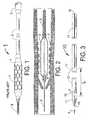
- FIG. 1is a side view of a prior art stent delivery system 1 having a fixed guidewire 6 attached to the distal end of a balloon 4 onto which a stent 5 has been mounted.
- a shaft 2which extends for most of the length of the stent delivery system 1 is attached at its distal end to the balloon 4 and at its proximal end to a Luer fitting 3.
- This type of stent delivery systemis described in detail in US patent number 6,375,660 , referred to above). If angiography indicates that there has been an intimal dissection after the stent 5 is placed into an arterial stenosis, the Luer fitting 3 is cut off from the shaft 2 so that a rescue catheter can be advanced over the stent delivery system 1.
- FIG. 2illustrates the delivered stent 5' deployed into an artery with a deflated balloon 4' attached at its distal end to the guidewire 6 and at its proximal end to the shaft 2.
- a core wire 9 attached to the fixed guidewire 6can extend to the proximal end of the stent delivery system 1.
- FIG. 3is a side view of a rescue catheter 10 having a shaft 12 that extends for most of its length, an interior lumen 18 and a distal cone 11 located at a distal portion of the catheter 10.
- the shaft 12has an elongated slit 14 whose distal end 17 is situated between 0.5 and 20 cm from the proximal end of the cone 11.
- the cone 11has a hole at its distal end and at least one slit 15 that extends to and possibly beyond the distal end of the shaft 12.
- the length of the cone 11should be less than 10 cm and optimally approximately one cm.
- the length of the cylindrical shaft 12should be at least 100 cm and optimally longer than 125 cm.
- the inside diameter of the shaft 12should be just slightly larger than the maximum outside diameter of the stent delivery system 1.
- FIG. 4is a longitudinal cross section of a distal portion of the catheter 10 showing the distal cone 11, the shaft 12, the distal opening 13, a slit 15 and the lumen 18.
- the slit 15is shown extending into the shaft 12, it is envisioned that its proximal end could remain within the cone 11 or it could extend for as much as a centimeter into the shaft 12.
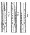
- FIGS. 5, 6 and 7illustrate how the catheter 10 would be used to place a conventional guidewire through an intimal dissection that extends beyond the edge of a stent.
- FIG. 5shows the catheter 10 inside an artery into which the stent 5' has been deployed. If there is an intimal dissection 8 extending beyond the edge of the stent 5', it can be detected by the interventional cardiologist using contrast medium. After an intimal dissection is detected, the Luer fitting 3 is cut off from the shaft 2 of the stent delivery system 1. The interventional cardiologist would then open the cone 11 and place it over the cut off proximal end of the shaft 2 of the stent delivery system 1.
- the interventional cardiologistwould then advance the catheter 10 over the shaft 2 until the proximal end of the shaft 2 could be pulled out of the slit 14. While holding the proximal end of the shaft 2 in one hand, the interventional cardiologist would, with his other hand, advance the catheter 10 over the stent delivery system 1 until the opening 13 of the cone 11 was advanced over the guidewire 6 and past beyond the intimal dissection 8. Because of its conical shape, and because the inside diameter of the end hole 13 would be approximately the same as the outside diameter of the guidewire 6, the distal end of the catheter 10 should readily pass through the dissection 8. Since it is expected that the diameter of the guidewire 6 would be 0.36 mm ( 0.014 inches), an optimal diameter for the opening 13 of the cone 11 would be approximately 0.36 mm (0.014 inches).
- the stent delivery system 1is pulled back out of the catheter 10 and out of the patient's body.
- a conventional guidewire 19is then inserted through the catheter 10 until its distal end lies distal to the intimal dissection 8. This condition is shown in FIG. 6 .
- the catheter 10is then removed from the patient's body and the guidewire 19 remains in place as shown in FIG. 7 . Because of the slit 14 in the side of the shaft 12 of the rescue catheter 10, a conventional length of approximately 135 cm could be used for the guidewire 19.
- An alternative methodwould be to use a guidewire 19 that is somewhat more than twice as long as a conventional guidewire.
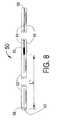
- FIG. 8shows an exemplary rescue catheter 50, known from EP-A-1 366 731 , having an open distal end 56 and central lumen 53.
- the catheter 50has a distal cylindrical section 52 of length L' and a proximal section 55 with a slit 54 that extends from the proximal end 58 of the catheter 50 to a widened opening 59 at the distal end of the slit 54 which is the proximal end of the distal section 52.
- the length L'is typically between 0.5 and 20 centimeters.
- the rescue catheter 50can be advanced over the cut off proximal end of the stent delivery system 1.
- the rescue catheter 50can either be advanced concentrically over the stent delivery system 1 in an "over-the-wire" type delivery or the rescue catheter 50 can be used in a rapid exchange method where only the distal section 52 is advanced concentrically over the stent delivery system 1.
- the shaft of the stent delivery system 1would lie inside the rescue catheter 50 only between the distal end 56 and the opening 59.
- the rescue catheter 50is advanced, more and more of the shaft of the stent delivery system 1 can be pressed inside of the proximal section 55 through the slit 54.
- the stent delivery system 1can be retracted through the lumen 53 of the rescue catheter 50.
- a guidewirecan then be advanced through the lumen 53 to provide guidance for additional recannalization devices.
- FIG. 9Aillustrates a first snap-on embodiment of the present invention rescue catheter 60 having a guidewire tube 64 of length L1 and distal end 65 with slit snap-on section 62 having length L2.
- L 1must be sufficiently long so that the distal end of the catheter 60 can reach the desired point in the human vascular system and is typically between 1 and 2 meters.
- L2is typically between 0.5 and 20 centimeters.
- FIG. 9Bshows an enlargement of the distal end 65 of the rescue catheter 60 of FIG. 9A .
- the distal end 65includes the slit snap-on section 62 with lumen 69 and slit opening 66. Also shown in FIG. 9B is the lumen 67 and tapered distal end 63 of the guidewire tube 64.
- the tapered distal end 63facilitates penetration through a vascular obstruction such as an intimal dissection.
- the rescue catheter 60does not require that the fitting at the proximal end of the stent delivery system 1 be cut off.
- the slit snap-on section 62is designed to be snapped onto the shaft 2 of the stent delivery system 1 of FIGs.
- the rescue cathetercan be advanced over the shaft 2 and beyond until the distal end 63 of the guidewire tube 64 lies beyond the vascular obstruction.
- a guidewirecan than be advanced through the lumen 67 of the guidewire tube 64 until the distal end of the guidewire lies beyond the vascular obstruction.
- the rescue catheter 60 and stent delivery system 1can then be removed from the body and the guidewire can be used to perform additional procedures such as stent delivery, to recannalize the vessel.
- FIG. 10Aillustrates a second snap-on embodiment of the present invention rescue catheter 70 having a guidewire tube 74 of length L3 with guidewire lumen 71.
- the catheter 70also has a distal end 80 with tapered slit snap-on section 82 having length L4.
- L3must be sufficiently long so that the distal end of the catheter 70 can reach the desired point in the human vascular system and is typically between 1 and 2 meters.
- the rescue catheter 70also has additional slit snap-on segments 77 and 79 where the slit snap-on segment 77 lies a distance L5 proximal to the proximal end of the slit snap-on section 82 and the slit snap-on segment 79 lies a distance L6 proximal to the proximal end of the snap-on segment 77.
- the distances L5 and L6can be as short as 1 cm or as long as a meter.
- the rescue catheter 70has two slit snap on segments 77 and 79, it is envisioned that it could have no slit snap-on segments such as the rescue catheter 60 of FIGs. 9A and 9B or it could have any number from 1 to 100 of the slit snap-on segments.
- the slit snap-on segmentsimprove the delivery of the rescue catheter 70 by keeping the guidewire tube 74 in close proximity to the shaft 2 of the stent delivery system 1 of FIGs 1 and 2 .
- the slit snap-on segments 77 and 79can be tapered similar to the distal slit snap-on section 82. While the slit snap-on segments 77 and 79 are shown in FIG. 10A as being relatively short compared to the distal slit snap-on section 82, it is envisioned that the slit snap-on segments 77 and 79 can be of equal or greater length than the distal slit snap-on section 82.
- FIG. 10Bshows an enlargement of the distal end 80 of the rescue catheter 70 of FIG. 10A .
- the distal end 80includes the tapered slit snap-on section 82 with lumen 89 and slit opening 86.
- the tapered slit snap-on section 82has a tapered distal end 84 and a tapered proximal end 88 which facilitate penetration through a vascular obstruction and improved delivery over the stent delivery system of FIGs. 1 and 2 .
- the tapered distal end 73 of the guidewire tube 74which facilitates penetration through a vascular obstruction such as an intimal dissection.
- the rescue catheter 70does not require that the fitting at the proximal end of the stent delivery system 1 be cut off.
- the tapered slit snap-on distal section 82is designed to be snapped onto the shaft 2 of the stent delivery system 1 of FIGs. 1 and 2 . This is done by pressing the shaft 2 through the slit 86 until the shaft 2 snaps into the lumen 89 of the slit snap-on section 82.
- the rescue cathetercan then be advanced over the shaft 2 and beyond until the distal end 73 of the guidewire tube 74 lies beyond the vascular obstruction.
- a guidewirecan than be advanced through the lumen 71 of the guidewire tube 74 until the distal end of the guidewire lies beyond the vascular obstruction.
- the rescue catheter 70 and stent delivery system 1can then be removed from the body and the guidewire can be used to perform additional procedures such as stent delivery, to recannalize the vessel.
- both proximal end 88 and distal end 84 of the slit snap-on section 82are tapered, it is envisioned that only one of the ends 88 and 84 or neither of the ends 88 and 84 need be tapered.
- the methodfurther comprises the following step:
- the methodfurther comprises the following steps:
Landscapes
- Health & Medical Sciences (AREA)
- Engineering & Computer Science (AREA)
- Biomedical Technology (AREA)
- Cardiology (AREA)
- Oral & Maxillofacial Surgery (AREA)
- Transplantation (AREA)
- Heart & Thoracic Surgery (AREA)
- Vascular Medicine (AREA)
- Life Sciences & Earth Sciences (AREA)
- Animal Behavior & Ethology (AREA)
- General Health & Medical Sciences (AREA)
- Public Health (AREA)
- Veterinary Medicine (AREA)
- Media Introduction/Drainage Providing Device (AREA)
- Prostheses (AREA)
Abstract
Description
- This invention is in the field of catheters used to treat intimal dissections which result from the placement of a stent into an artery, such as a coronary artery.
- In
US patent application serial number 09/444,104 , now U. S. Patent No.6,375,660 , a stent delivery catheter is described that has a fixed guidewire at its distal end. Although this system for delivering a stent into a vessel of the human body has the advantage of providing an extremely small outside diameter for easy insertion through even the narrowest of arterial stenoses, it does not provide for those few cases when an intimal dissection occurs after stent implantation. Specifically, if a separate guidewire is used during stent implantation, it can be kept in place after the stent delivery catheter is removed, thus allowing insertion of a second stent delivery system over the guidewire to repair any intimal dissection. However, if the guidewire is fixed to the stent delivery catheter, it will be removed with the stent delivery catheter after the stent has been delivered. Without a guidewire through that portion of the artery where an intimal dissection has occurred, it can be extremely difficult to place a second stent delivery catheter to deliver a second stent to repair such an intimal dissection. EP-A-1 366 731 discloses a rescue catheter that is designed to be placed over a fixed wire stent delivery catheter after angiography reveals that an intimal dissection has occurred typically as an edge dissection either just proximal or just distal to the stent.- The features known in combination from
EP-A-1 366 731 are set out in the preamble of the accompanying claim 1. - There is also disclosed in
EP-A-1 366 731 a method for using such a catheter to repair an intimal dissection. It should be understood that an intimal dissection that is in close proximity to the edge of an implanted stent is called an "edge dissection". - As previously stated,
US patent application serial number 09/444,104 (nowUS 6,375,660 ) describes a fixed guidewire stent delivery catheter with an extremely small outside diameter which can be used to deliver a stent through a very tight arterial stenosis. After the stent on the stent delivery catheter has been delivered into the arterial wall, the balloon is deflated and the fixed guidewire stent delivery catheter would be left in place. Contrast medium would then be delivered to the site of the dilated stenosis to indicate if there is any arterial wall dissection. Such an intimal dissection would typically occur near the proximal or distal edge of the stent. - In most cases there will be no edge dissection, the stent delivery catheter would be removed from the body and the stent implantation would be considered to be successfully completed.
- According to the method of
EP-A-1366731 , if however, the angiography with the contrast medium indicates that an edge dissection has occurred, then the fixed guidewire stent delivery catheter would be left in place with its balloon deflated. The Luer fitting at the proximal end of the stent delivery catheter would then be cut off and a rescue in the form of a rescue catheter would be advanced over the stent delivery catheter. The rescue catheter would then be advanced until its distal end extended distally beyond the site of the edge dissection. The fixed wire stent delivery catheter would then be pulled out of the body through the rescue catheter and a conventional guidewire would be inserted through the rescue catheter. The rescue catheter would then be removed leaving the guidewire in place. A conventional stent delivery catheter would then be used to deliver a second stent to the site of the intimal dissection at the edge of the first implanted stent, thus repairing the dissection. - According to the present invention there is provided a rapid exchange rescue catheter that is delivered in a manner similar to a rapid exchange or monorail type angioplasty catheter, except the guiding device is the fixed wire stent delivery system. To be most effective and not require cutting of the fixed wire stent delivery system, the rapid exchange rescue catheter is designed to "snap onto" the shaft of the fixed wire stent delivery system where a guidewire tube is attached to the snap on mechanism and can then be advanced over the fixed wire stent delivery system until the distal end of the guidewire tube is past the intimal dissection in the artery. A guidewire is then advanced through the guidewire tube until it is past the dissection allowing a normal stent procedure to follow.
- Documents
US 5738667 andUS 2005/0059991 describe respectively an exchange member and a guide member comprising snap-on sections to snap on delivery systems or PTCA catheters, but not at the distal end of guidewire tubes. - According to the present invention, a rescue catheter is designed to be placed over a fixed guidewire stent delivery system if angiography indicates that an intimal dissection has occurred, the rescue catheter being designed for placement of a conventional guidewire through it so that a second stent delivery system can be advanced over the guidewire to deliver a stent to repair the intimal dissection.
- The rescue catheter treats an intimal dissection created by the delivery of a stent from a fixed guidewire stent delivery system.
- Still further, there is provided a rapid exchange rescue catheter whose distal section is designed to snap onto and be guided by the shaft of a fixed wire stent delivery system.
- Thus, there is provided a rescue catheter of the type defined in the accompanying claim 1. Preferred aspects are set out in the dependent claims.
FIG. 1 is a side view of a prior art fixed guidewire stent delivery system shown with the stent mounted onto the balloon.FIG. 2 is a longitudinal cross section of the fixed guidewire stent delivery system with the stent shown delivered into an arterial stenosis, the balloon is deflated an a distal intimal dissection has occurred.FIG. 3 is a side view of the rescue catheter that is adapted to pass through an intimal dissection.FIG. 4 is a longitudinal cross section of a distal portion of the rescue catheter at section 4-4 ofFIG. 3 .FIG. 5 shows the rescue catheter placed over the fixed guidewire stent delivery system and through an intimal dissection.FIG. 6 shows the rescue catheter in place with the stent delivery system removed and a conventional guidewire placed through the rescue catheter with its distal end placed beyond the intimal dissection.FIG. 7 shows the guidewire in place and the rescue catheter removed.FIG. 8 shows an exemplary rescue catheter having an open distal end.FIGs. 9A and 9B illustrate a first snap-on embodiment of the rescue catheter of the present invention.FIGs. 10A and 10B illustrate a second snap-on embodiment of the rescue catheter of the present invention having a tapered distal snap-on section for improved slideability.FIG. 1 is a side view of a prior art stent delivery system 1 having afixed guidewire 6 attached to the distal end of aballoon 4 onto which astent 5 has been mounted. Ashaft 2 which extends for most of the length of the stent delivery system 1 is attached at its distal end to theballoon 4 and at its proximal end to aLuer fitting 3. (This type of stent delivery system is described in detail inUS patent number 6,375,660 , referred to above). If angiography indicates that there has been an intimal dissection after thestent 5 is placed into an arterial stenosis, theLuer fitting 3 is cut off from theshaft 2 so that a rescue catheter can be advanced over the stent delivery system 1.FIG. 2 illustrates the delivered stent 5' deployed into an artery with a deflated balloon 4' attached at its distal end to theguidewire 6 and at its proximal end to theshaft 2. Acore wire 9 attached to thefixed guidewire 6 can extend to the proximal end of the stent delivery system 1.FIG. 3 is a side view of arescue catheter 10 having ashaft 12 that extends for most of its length, aninterior lumen 18 and adistal cone 11 located at a distal portion of thecatheter 10. Theshaft 12 has anelongated slit 14 whosedistal end 17 is situated between 0.5 and 20 cm from the proximal end of thecone 11. Thecone 11 has a hole at its distal end and at least oneslit 15 that extends to and possibly beyond the distal end of theshaft 12. The length of thecone 11 should be less than 10 cm and optimally approximately one cm. The length of thecylindrical shaft 12 should be at least 100 cm and optimally longer than 125 cm. The inside diameter of theshaft 12 should be just slightly larger than the maximum outside diameter of the stent delivery system 1.FIG. 4 is a longitudinal cross section of a distal portion of thecatheter 10 showing thedistal cone 11, theshaft 12, the distal opening 13, aslit 15 and thelumen 18. Although theslit 15 is shown extending into theshaft 12, it is envisioned that its proximal end could remain within thecone 11 or it could extend for as much as a centimeter into theshaft 12. Furthermore, it should be understood that there could be as many as fourslits 15 around the circumference of thecone 11 or as few as one.FIGS. 5, 6 and 7 illustrate how thecatheter 10 would be used to place a conventional guidewire through an intimal dissection that extends beyond the edge of a stent.FIG. 5 shows thecatheter 10 inside an artery into which the stent 5' has been deployed. If there is an intimal dissection 8 extending beyond the edge of the stent 5', it can be detected by the interventional cardiologist using contrast medium. After an intimal dissection is detected, the Luer fitting 3 is cut off from theshaft 2 of the stent delivery system 1. The interventional cardiologist would then open thecone 11 and place it over the cut off proximal end of theshaft 2 of the stent delivery system 1. The interventional cardiologist would then advance thecatheter 10 over theshaft 2 until the proximal end of theshaft 2 could be pulled out of theslit 14. While holding the proximal end of theshaft 2 in one hand, the interventional cardiologist would, with his other hand, advance thecatheter 10 over the stent delivery system 1 until theopening 13 of thecone 11 was advanced over theguidewire 6 and past beyond the intimal dissection 8. Because of its conical shape, and because the inside diameter of theend hole 13 would be approximately the same as the outside diameter of theguidewire 6, the distal end of thecatheter 10 should readily pass through the dissection 8. Since it is expected that the diameter of theguidewire 6 would be 0.36 mm ( 0.014 inches), an optimal diameter for theopening 13 of thecone 11 would be approximately 0.36 mm (0.014 inches).- After the
catheter 10 is positioned as shown inFIG. 5 , the stent delivery system 1 is pulled back out of thecatheter 10 and out of the patient's body. Aconventional guidewire 19 is then inserted through thecatheter 10 until its distal end lies distal to the intimal dissection 8. This condition is shown inFIG. 6 . Thecatheter 10 is then removed from the patient's body and theguidewire 19 remains in place as shown inFIG. 7 . Because of theslit 14 in the side of theshaft 12 of therescue catheter 10, a conventional length of approximately 135 cm could be used for theguidewire 19. An alternative method would be to use aguidewire 19 that is somewhat more than twice as long as a conventional guidewire. FIG. 8 shows anexemplary rescue catheter 50, known fromEP-A-1 366 731 , having an opendistal end 56 andcentral lumen 53. Thecatheter 50 has a distalcylindrical section 52 of length L' and aproximal section 55 with aslit 54 that extends from theproximal end 58 of thecatheter 50 to a widenedopening 59 at the distal end of theslit 54 which is the proximal end of thedistal section 52. The length L' is typically between 0.5 and 20 centimeters.- Similar to the
rescue catheter 10 ofFIGs. 4 through 7 , therescue catheter 50 can be advanced over the cut off proximal end of the stent delivery system 1. Therescue catheter 50 can either be advanced concentrically over the stent delivery system 1 in an "over-the-wire" type delivery or therescue catheter 50 can be used in a rapid exchange method where only thedistal section 52 is advanced concentrically over the stent delivery system 1. Thus the shaft of the stent delivery system 1 would lie inside therescue catheter 50 only between thedistal end 56 and theopening 59. Ideally as therescue catheter 50 is advanced, more and more of the shaft of the stent delivery system 1 can be pressed inside of theproximal section 55 through theslit 54. Once therescue catheter 50 has been advanced distally to the desired location, the stent delivery system 1 can be retracted through thelumen 53 of therescue catheter 50. A guidewire can then be advanced through thelumen 53 to provide guidance for additional recannalization devices. FIG. 9A illustrates a first snap-on embodiment of the presentinvention rescue catheter 60 having aguidewire tube 64 of length L1 anddistal end 65 with slit snap-onsection 62 having length L2. L 1 must be sufficiently long so that the distal end of thecatheter 60 can reach the desired point in the human vascular system and is typically between 1 and 2 meters. L2 is typically between 0.5 and 20 centimeters.FIG. 9B shows an enlargement of thedistal end 65 of therescue catheter 60 ofFIG. 9A . Thedistal end 65 includes the slit snap-onsection 62 withlumen 69 and slitopening 66. Also shown inFIG. 9B is thelumen 67 and tapereddistal end 63 of theguidewire tube 64. The tapereddistal end 63 facilitates penetration through a vascular obstruction such as an intimal dissection. Unlike therescue catheters FIGs. 3 and8 , therescue catheter 60 does not require that the fitting at the proximal end of the stent delivery system 1 be cut off. The slit snap-onsection 62 is designed to be snapped onto theshaft 2 of the stent delivery system 1 ofFIGs. 1 and 2 . This is done by pressing theshaft 2 through theslit 66 until theshaft 2 snaps into thelumen 69 of the slit snap-onsection 62. The rescue catheter can be advanced over theshaft 2 and beyond until thedistal end 63 of theguidewire tube 64 lies beyond the vascular obstruction. A guidewire can than be advanced through thelumen 67 of theguidewire tube 64 until the distal end of the guidewire lies beyond the vascular obstruction. Therescue catheter 60 and stent delivery system 1 can then be removed from the body and the guidewire can be used to perform additional procedures such as stent delivery, to recannalize the vessel.FIG. 10A illustrates a second snap-on embodiment of the presentinvention rescue catheter 70 having aguidewire tube 74 of length L3 with guidewire lumen 71. Thecatheter 70 also has adistal end 80 with tapered slit snap-onsection 82 having length L4. L3 must be sufficiently long so that the distal end of thecatheter 70 can reach the desired point in the human vascular system and is typically between 1 and 2 meters.- L4 is typically between 0.5 and 20 centimeters. The
rescue catheter 70 also has additional slit snap-onsegments segment 77 lies a distance L5 proximal to the proximal end of the slit snap-onsection 82 and the slit snap-onsegment 79 lies a distance L6 proximal to the proximal end of the snap-onsegment 77. The distances L5 and L6 can be as short as 1 cm or as long as a meter. - Although the
rescue catheter 70 has two slit snap onsegments rescue catheter 60 ofFIGs. 9A and 9B or it could have any number from 1 to 100 of the slit snap-on segments. The slit snap-on segments improve the delivery of therescue catheter 70 by keeping theguidewire tube 74 in close proximity to theshaft 2 of the stent delivery system 1 ofFIGs 1 and 2 . - It is also envisioned that the slit snap-on
segments section 82. While the slit snap-onsegments FIG. 10A as being relatively short compared to the distal slit snap-onsection 82, it is envisioned that the slit snap-onsegments section 82. FIG. 10B shows an enlargement of thedistal end 80 of therescue catheter 70 ofFIG. 10A . Thedistal end 80 includes the tapered slit snap-onsection 82 withlumen 89 and slitopening 86. The tapered slit snap-onsection 82 has a tapereddistal end 84 and a taperedproximal end 88 which facilitate penetration through a vascular obstruction and improved delivery over the stent delivery system ofFIGs. 1 and 2 .- Also shown in
FIG. 10B is the tapereddistal end 73 of theguidewire tube 74 which facilitates penetration through a vascular obstruction such as an intimal dissection. Unlike therescue catheters FIGs. 3 and8 , therescue catheter 70 does not require that the fitting at the proximal end of the stent delivery system 1 be cut off. The tapered slit snap-ondistal section 82 is designed to be snapped onto theshaft 2 of the stent delivery system 1 ofFIGs. 1 and 2 . This is done by pressing theshaft 2 through theslit 86 until theshaft 2 snaps into thelumen 89 of the slit snap-onsection 82. The rescue catheter can then be advanced over theshaft 2 and beyond until thedistal end 73 of theguidewire tube 74 lies beyond the vascular obstruction. A guidewire can than be advanced through the lumen 71 of theguidewire tube 74 until the distal end of the guidewire lies beyond the vascular obstruction. Therescue catheter 70 and stent delivery system 1 can then be removed from the body and the guidewire can be used to perform additional procedures such as stent delivery, to recannalize the vessel. Although bothproximal end 88 anddistal end 84 of the slit snap-onsection 82 are tapered, it is envisioned that only one of theends ends - There is also disclosed, but not claimed, a method for repairing an intimal dissection resulting from the placement of a stent that has been delivered from a fixed guidewire stent delivery catheter, the method comprising the following steps:
- a) advancing a fixed guidewire stent delivery catheter into a stenosed artery of a human subject;
- b) inflating a balloon placed at a distal portion of the fixed guidewire stent delivery catheter so as to deliver a stent mounted onto the balloon into a stenosis of the stenosed artery;
- c) deflating the balloon;
- d) snapping a slit snap-on section of a rescue catheter having a guidewire tube, the guidewire tube having a distal end, over the shaft of the fixed guidewire stent delivery catheter;
- e) advancing the rescue catheter until the guidewire tube's distal end lies distal to the observed intimal dissection;
- f) advancing a guidewire through the guidewire tube of the rescue catheter until the guidewire extends beyond the observed intimal dissection;
- g) removing the fixed guidewire stent delivery catheter and rescue catheter from the body of the patient.
- Optionally, the method further comprises the following step:
- pressing the shaft of the fixed guidewire stent delivery catheter through the slit of at least one slit snap-on segment.
- Optionally, the method further comprises the following steps:
- a) placing a stent delivery catheter over the guidewire so that a stent at a distal portion of the stent delivery catheter is situated at the site of the intimal dissection;
- b) delivering the stent into the intimal dissection so as to repair the intimal dissection; and
- c) removing the stent delivery catheter and the guidewire from the human subject.
- Various other modifications, adaptations, and alternative designs are of course possible in light of the above teachings. Therefore, it should be understood at this time that within the scope of the appended claims, the invention may be practiced otherwise than as specifically described herein.
Claims (9)
- A rescue catheter (60; 70) adapted for placement over a fixed guidewire stent delivery catheter (1) after an intimal dissection has been detected following the placement of a stent (5') into an artery of a human body, the rescue catheter comprising:a guidewire tube (64; 74) having proximal and distal ends (63; 73), and a slit (66; 86),characterised in that the rescue catheter is a rapid exchange rescue catheter (60, 70) and the slit is in a slit snap-on section designed to snap onto the shaft of the fixed guidewire stent delivery catheter (62; 82) fixedly attached near the distal end (63; 73) of the guidewire tube (64; 74).
- The rescue catheter of claim 1 wherein the distal end (63; 73) of the guidewire tube is tapered.
- The rescue catheter of claim 1 or claim 2 wherein the slit snap-on section (82) has a tapered distal end (84).
- The rescue catheter of claim 1, 2 or 3 wherein the slit snap-on section (82) has a tapered proximal end (88).
- The rescue catheter of any of claims 1 to 4 wherein the slit snap-on section (62; 82) has a length of less than 20 centimeters.
- The rescue catheter of any of claims 1 to 5 wherein the slit snap-on section (62; 82) has a length of more than 1 centimeter.
- The rescue catheter of any of claims 1 to 6 further comprising at least one slit snap-on segment (77; 79) fixedly attached to the guidewire tube (74) at a location proximal to the slit snap-on section (82).
- The rescue catheter of claim 7 wherein the at least one slit snap-on segment (77; 79) has tapered distal end.
- The rescue catheter of claim 7 or claim 8 wherein the at least one slit snap-on segment (77; 79) has tapered proximal end.
Applications Claiming Priority (1)
| Application Number | Priority Date | Filing Date | Title |
|---|---|---|---|
| US11/243,647US20060069423A1 (en) | 1999-11-22 | 2005-10-05 | Means and method for treating an intimal dissection after stent implantation |
Publications (2)
| Publication Number | Publication Date |
|---|---|
| EP1772121A1 EP1772121A1 (en) | 2007-04-11 |
| EP1772121B1true EP1772121B1 (en) | 2010-11-24 |
Family
ID=37441571
Family Applications (1)
| Application Number | Title | Priority Date | Filing Date |
|---|---|---|---|
| EP06255131ANot-in-forceEP1772121B1 (en) | 2005-10-05 | 2006-10-04 | Catheter for treating an intimal dissection after stent implantation |
Country Status (5)
| Country | Link |
|---|---|
| US (1) | US20060069423A1 (en) |
| EP (1) | EP1772121B1 (en) |
| AT (1) | ATE489059T1 (en) |
| DE (1) | DE602006018406D1 (en) |
| ES (1) | ES2354447T3 (en) |
Families Citing this family (1)
| Publication number | Priority date | Publication date | Assignee | Title |
|---|---|---|---|---|
| WO2019234659A2 (en)* | 2018-06-08 | 2019-12-12 | Yoav Shaked | Systems, devices and methods for controlled vessel lesion dissection |
Citations (2)
| Publication number | Priority date | Publication date | Assignee | Title |
|---|---|---|---|---|
| US5738667A (en)* | 1992-03-30 | 1998-04-14 | Cordis Corporation | Rapid exchange catheter system |
| US20050059991A1 (en)* | 1999-05-20 | 2005-03-17 | Shanley John F. | Expandable medical device delivery system and method |
Family Cites Families (28)
| Publication number | Priority date | Publication date | Assignee | Title |
|---|---|---|---|---|
| US5275622A (en)* | 1983-12-09 | 1994-01-04 | Harrison Medical Technologies, Inc. | Endovascular grafting apparatus, system and method and devices for use therewith |
| US5669936A (en)* | 1983-12-09 | 1997-09-23 | Endovascular Technologies, Inc. | Endovascular grafting system and method for use therewith |
| US6083220A (en)* | 1990-03-13 | 2000-07-04 | The Regents Of The University Of California | Endovascular electrolytically detachable wire and tip for the formation of thrombus in arteries, veins, aneurysms, vascular malformations and arteriovenous fistulas |
| DK124690D0 (en)* | 1990-05-18 | 1990-05-18 | Henning Rud Andersen | FAT PROTECTION FOR IMPLEMENTATION IN THE BODY FOR REPLACEMENT OF NATURAL FLEET AND CATS FOR USE IN IMPLEMENTING A SUCH FAT PROTECTION |
| CA2079417C (en)* | 1991-10-28 | 2003-01-07 | Lilip Lau | Expandable stents and method of making same |
| US5357978A (en)* | 1993-01-12 | 1994-10-25 | Medtronic, Inc. | Rapid exchange guidewire loading attachment |
| US5891108A (en)* | 1994-09-12 | 1999-04-06 | Cordis Corporation | Drug delivery stent |
| US5681344A (en)* | 1995-02-06 | 1997-10-28 | Wilson-Cook Medical Inc. | Esophageal dilation balloon catheter containing flexible nitinol wire |
| US5766203A (en)* | 1995-07-20 | 1998-06-16 | Intelliwire, Inc. | Sheath with expandable distal extremity and balloon catheters and stents for use therewith and method |
| US5748745A (en)* | 1996-02-26 | 1998-05-05 | Bedini Electronics, Inc. | Analog vector processor and method for producing a binaural signal |
| US6071285A (en)* | 1996-03-25 | 2000-06-06 | Lashinski; Robert D. | Rapid exchange folded balloon catheter and stent delivery system |
| US6596020B2 (en)* | 1996-11-04 | 2003-07-22 | Advanced Stent Technologies, Inc. | Method of delivering a stent with a side opening |
| US5792144A (en)* | 1997-03-31 | 1998-08-11 | Cathco, Inc. | Stent delivery catheter system |
| US5891154A (en)* | 1997-05-06 | 1999-04-06 | Advanced Cardiovascular System, Inc. | Passive perfusion stent delivery system |
| US6056722A (en)* | 1997-09-18 | 2000-05-02 | Iowa-India Investments Company Limited Of Douglas | Delivery mechanism for balloons, drugs, stents and other physical/mechanical agents and methods of use |
| US6254627B1 (en)* | 1997-09-23 | 2001-07-03 | Diseno Y Desarrollo Medico S.A. De C.V. | Non-thrombogenic stent jacket |
| US6159195A (en)* | 1998-02-19 | 2000-12-12 | Percusurge, Inc. | Exchange catheter and method of use |
| US6280467B1 (en)* | 1998-02-26 | 2001-08-28 | World Medical Manufacturing Corporation | Delivery system for deployment and endovascular assembly of a multi-stage stented graft |
| US6095990A (en)* | 1998-08-31 | 2000-08-01 | Parodi; Juan Carlos | Guiding device and method for inserting and advancing catheters and guidewires into a vessel of a patient in endovascular treatments |
| US6280412B1 (en)* | 1999-06-17 | 2001-08-28 | Scimed Life Systems, Inc. | Stent securement by balloon modification |
| US7074235B1 (en)* | 1999-10-16 | 2006-07-11 | Sumit Roy | Low-profile, non-stented prosthesis for transluminal implantation |
| US6375660B1 (en)* | 1999-11-22 | 2002-04-23 | Cordis Corporation | Stent delivery system with a fixed guide wire |
| US6936065B2 (en)* | 1999-11-22 | 2005-08-30 | Cordis Corporation | Stent delivery system having a fixed guidewire |
| US6368344B1 (en)* | 1999-12-16 | 2002-04-09 | Advanced Cardiovascular Systems, Inc. | Stent deployment system with reinforced inner member |
| SE522805C2 (en)* | 2000-06-22 | 2004-03-09 | Jan Otto Solem | Stent Application System |
| US6537294B1 (en)* | 2000-10-17 | 2003-03-25 | Advanced Cardiovascular Systems, Inc. | Delivery systems for embolic filter devices |
| US7273491B2 (en)* | 2002-05-30 | 2007-09-25 | Cordis Corporation | Means and method for treating an intimal dissection after stent implantation |
| US20050101968A1 (en)* | 2003-11-12 | 2005-05-12 | Dadourian Daniel G. | Ostial locator device and methods for transluminal interventions |
- 2005
- 2005-10-05USUS11/243,647patent/US20060069423A1/ennot_activeAbandoned
- 2006
- 2006-10-04ATAT06255131Tpatent/ATE489059T1/ennot_activeIP Right Cessation
- 2006-10-04DEDE602006018406Tpatent/DE602006018406D1/enactiveActive
- 2006-10-04ESES06255131Tpatent/ES2354447T3/enactiveActive
- 2006-10-04EPEP06255131Apatent/EP1772121B1/ennot_activeNot-in-force
Patent Citations (2)
| Publication number | Priority date | Publication date | Assignee | Title |
|---|---|---|---|---|
| US5738667A (en)* | 1992-03-30 | 1998-04-14 | Cordis Corporation | Rapid exchange catheter system |
| US20050059991A1 (en)* | 1999-05-20 | 2005-03-17 | Shanley John F. | Expandable medical device delivery system and method |
Also Published As
| Publication number | Publication date |
|---|---|
| ES2354447T3 (en) | 2011-03-15 |
| US20060069423A1 (en) | 2006-03-30 |
| EP1772121A1 (en) | 2007-04-11 |
| DE602006018406D1 (en) | 2011-01-05 |
| ATE489059T1 (en) | 2010-12-15 |
Similar Documents
| Publication | Publication Date | Title |
|---|---|---|
| US6196995B1 (en) | Reinforced edge exchange catheter | |
| EP3466476B1 (en) | Guidewire fixation | |
| US6605062B1 (en) | Catheter for guidewire support or exchange | |
| EP1534181B1 (en) | Centering catheter | |
| US6254549B1 (en) | Guidewire replacement device with flexible intermediate section | |
| US5380283A (en) | Rapid exchange type dilatation catheter | |
| EP0891171B1 (en) | Rapid exchange delivery cathether system | |
| US20020055732A1 (en) | Catheter assembly and method for positioning the same at a bifurcated vessel | |
| US9089675B2 (en) | Guidewire support system and guidewire | |
| US20020055733A1 (en) | Catheter assembly and method of use | |
| EP0518205A1 (en) | Catheter system with catheter and guidewire exchange | |
| US20070293846A1 (en) | Dual Lumen Guidewire Support Catheter | |
| EP0820784A3 (en) | Balloon catheter and methods of use | |
| US7524303B1 (en) | Arterial obstruction treatment kit | |
| JP2004073870A (en) | Over-the-wire catheter with slider to grip guide wire | |
| US7875002B2 (en) | Stent delivery system and method of use | |
| EP1366731B1 (en) | A catheter for treating an intimal dissection | |
| EP2037997A2 (en) | Vascular catheter apparatus and method | |
| US20120150271A1 (en) | Buddy wire for the coronary arteries | |
| WO2006124353A2 (en) | Guidewire loader for bifurcated vessel | |
| US20040055926A1 (en) | Catheter packaging | |
| EP1772121B1 (en) | Catheter for treating an intimal dissection after stent implantation | |
| US20070213802A1 (en) | Bifurcation Stent Delivery Catheter and Method | |
| US7273486B2 (en) | Catheter with a convertible proximal catheter shaft | |
| US20080091151A1 (en) | Means and method for treating an intimal dissection after stent implantation |
Legal Events
| Date | Code | Title | Description |
|---|---|---|---|
| PUAI | Public reference made under article 153(3) epc to a published international application that has entered the european phase | Free format text:ORIGINAL CODE: 0009012 | |
| AK | Designated contracting states | Kind code of ref document:A1 Designated state(s):AT BE BG CH CY CZ DE DK EE ES FI FR GB GR HU IE IS IT LI LT LU LV MC NL PL PT RO SE SI SK TR | |
| AX | Request for extension of the european patent | Extension state:AL BA HR MK YU | |
| 17P | Request for examination filed | Effective date:20070926 | |
| 17Q | First examination report despatched | Effective date:20071025 | |
| AKX | Designation fees paid | Designated state(s):AT BE BG CH CY CZ DE DK EE ES FI FR GB GR HU IE IS IT LI LT LU LV MC NL PL PT RO SE SI SK TR | |
| GRAP | Despatch of communication of intention to grant a patent | Free format text:ORIGINAL CODE: EPIDOSNIGR1 | |
| GRAS | Grant fee paid | Free format text:ORIGINAL CODE: EPIDOSNIGR3 | |
| GRAA | (expected) grant | Free format text:ORIGINAL CODE: 0009210 | |
| AK | Designated contracting states | Kind code of ref document:B1 Designated state(s):AT BE BG CH CY CZ DE DK EE ES FI FR GB GR HU IE IS IT LI LT LU LV MC NL PL PT RO SE SI SK TR | |
| REG | Reference to a national code | Ref country code:GB Ref legal event code:FG4D | |
| REG | Reference to a national code | Ref country code:CH Ref legal event code:EP | |
| REG | Reference to a national code | Ref country code:IE Ref legal event code:FG4D | |
| REF | Corresponds to: | Ref document number:602006018406 Country of ref document:DE Date of ref document:20110105 Kind code of ref document:P | |
| REG | Reference to a national code | Ref country code:NL Ref legal event code:T3 | |
| REG | Reference to a national code | Ref country code:ES Ref legal event code:FG2A Effective date:20110303 | |
| LTIE | Lt: invalidation of european patent or patent extension | Effective date:20101124 | |
| PG25 | Lapsed in a contracting state [announced via postgrant information from national office to epo] | Ref country code:LT Free format text:LAPSE BECAUSE OF FAILURE TO SUBMIT A TRANSLATION OF THE DESCRIPTION OR TO PAY THE FEE WITHIN THE PRESCRIBED TIME-LIMIT Effective date:20101124 | |
| PG25 | Lapsed in a contracting state [announced via postgrant information from national office to epo] | Ref country code:CY Free format text:LAPSE BECAUSE OF FAILURE TO SUBMIT A TRANSLATION OF THE DESCRIPTION OR TO PAY THE FEE WITHIN THE PRESCRIBED TIME-LIMIT Effective date:20101124 Ref country code:IS Free format text:LAPSE BECAUSE OF FAILURE TO SUBMIT A TRANSLATION OF THE DESCRIPTION OR TO PAY THE FEE WITHIN THE PRESCRIBED TIME-LIMIT Effective date:20110324 Ref country code:BG Free format text:LAPSE BECAUSE OF FAILURE TO SUBMIT A TRANSLATION OF THE DESCRIPTION OR TO PAY THE FEE WITHIN THE PRESCRIBED TIME-LIMIT Effective date:20110224 Ref country code:AT Free format text:LAPSE BECAUSE OF FAILURE TO SUBMIT A TRANSLATION OF THE DESCRIPTION OR TO PAY THE FEE WITHIN THE PRESCRIBED TIME-LIMIT Effective date:20101124 Ref country code:SE Free format text:LAPSE BECAUSE OF FAILURE TO SUBMIT A TRANSLATION OF THE DESCRIPTION OR TO PAY THE FEE WITHIN THE PRESCRIBED TIME-LIMIT Effective date:20101124 Ref country code:PT Free format text:LAPSE BECAUSE OF FAILURE TO SUBMIT A TRANSLATION OF THE DESCRIPTION OR TO PAY THE FEE WITHIN THE PRESCRIBED TIME-LIMIT Effective date:20110324 Ref country code:SI Free format text:LAPSE BECAUSE OF FAILURE TO SUBMIT A TRANSLATION OF THE DESCRIPTION OR TO PAY THE FEE WITHIN THE PRESCRIBED TIME-LIMIT Effective date:20101124 Ref country code:LV Free format text:LAPSE BECAUSE OF FAILURE TO SUBMIT A TRANSLATION OF THE DESCRIPTION OR TO PAY THE FEE WITHIN THE PRESCRIBED TIME-LIMIT Effective date:20101124 Ref country code:FI Free format text:LAPSE BECAUSE OF FAILURE TO SUBMIT A TRANSLATION OF THE DESCRIPTION OR TO PAY THE FEE WITHIN THE PRESCRIBED TIME-LIMIT Effective date:20101124 | |
| PG25 | Lapsed in a contracting state [announced via postgrant information from national office to epo] | Ref country code:GR Free format text:LAPSE BECAUSE OF FAILURE TO SUBMIT A TRANSLATION OF THE DESCRIPTION OR TO PAY THE FEE WITHIN THE PRESCRIBED TIME-LIMIT Effective date:20110225 | |
| PG25 | Lapsed in a contracting state [announced via postgrant information from national office to epo] | Ref country code:CZ Free format text:LAPSE BECAUSE OF FAILURE TO SUBMIT A TRANSLATION OF THE DESCRIPTION OR TO PAY THE FEE WITHIN THE PRESCRIBED TIME-LIMIT Effective date:20101124 Ref country code:EE Free format text:LAPSE BECAUSE OF FAILURE TO SUBMIT A TRANSLATION OF THE DESCRIPTION OR TO PAY THE FEE WITHIN THE PRESCRIBED TIME-LIMIT Effective date:20101124 | |
| PG25 | Lapsed in a contracting state [announced via postgrant information from national office to epo] | Ref country code:SK Free format text:LAPSE BECAUSE OF FAILURE TO SUBMIT A TRANSLATION OF THE DESCRIPTION OR TO PAY THE FEE WITHIN THE PRESCRIBED TIME-LIMIT Effective date:20101124 Ref country code:PL Free format text:LAPSE BECAUSE OF FAILURE TO SUBMIT A TRANSLATION OF THE DESCRIPTION OR TO PAY THE FEE WITHIN THE PRESCRIBED TIME-LIMIT Effective date:20101124 Ref country code:DK Free format text:LAPSE BECAUSE OF FAILURE TO SUBMIT A TRANSLATION OF THE DESCRIPTION OR TO PAY THE FEE WITHIN THE PRESCRIBED TIME-LIMIT Effective date:20101124 Ref country code:RO Free format text:LAPSE BECAUSE OF FAILURE TO SUBMIT A TRANSLATION OF THE DESCRIPTION OR TO PAY THE FEE WITHIN THE PRESCRIBED TIME-LIMIT Effective date:20101124 | |
| PLBE | No opposition filed within time limit | Free format text:ORIGINAL CODE: 0009261 | |
| STAA | Information on the status of an ep patent application or granted ep patent | Free format text:STATUS: NO OPPOSITION FILED WITHIN TIME LIMIT | |
| 26N | No opposition filed | Effective date:20110825 | |
| REG | Reference to a national code | Ref country code:DE Ref legal event code:R097 Ref document number:602006018406 Country of ref document:DE Effective date:20110825 | |
| PG25 | Lapsed in a contracting state [announced via postgrant information from national office to epo] | Ref country code:MC Free format text:LAPSE BECAUSE OF NON-PAYMENT OF DUE FEES Effective date:20111031 | |
| REG | Reference to a national code | Ref country code:CH Ref legal event code:PL | |
| PG25 | Lapsed in a contracting state [announced via postgrant information from national office to epo] | Ref country code:CH Free format text:LAPSE BECAUSE OF NON-PAYMENT OF DUE FEES Effective date:20111031 Ref country code:LI Free format text:LAPSE BECAUSE OF NON-PAYMENT OF DUE FEES Effective date:20111031 | |
| REG | Reference to a national code | Ref country code:IE Ref legal event code:MM4A | |
| PG25 | Lapsed in a contracting state [announced via postgrant information from national office to epo] | Ref country code:IE Free format text:LAPSE BECAUSE OF NON-PAYMENT OF DUE FEES Effective date:20111004 | |
| PG25 | Lapsed in a contracting state [announced via postgrant information from national office to epo] | Ref country code:LU Free format text:LAPSE BECAUSE OF NON-PAYMENT OF DUE FEES Effective date:20111004 | |
| PG25 | Lapsed in a contracting state [announced via postgrant information from national office to epo] | Ref country code:TR Free format text:LAPSE BECAUSE OF FAILURE TO SUBMIT A TRANSLATION OF THE DESCRIPTION OR TO PAY THE FEE WITHIN THE PRESCRIBED TIME-LIMIT Effective date:20101124 | |
| PG25 | Lapsed in a contracting state [announced via postgrant information from national office to epo] | Ref country code:HU Free format text:LAPSE BECAUSE OF FAILURE TO SUBMIT A TRANSLATION OF THE DESCRIPTION OR TO PAY THE FEE WITHIN THE PRESCRIBED TIME-LIMIT Effective date:20101124 | |
| REG | Reference to a national code | Ref country code:FR Ref legal event code:PLFP Year of fee payment:11 | |
| REG | Reference to a national code | Ref country code:FR Ref legal event code:PLFP Year of fee payment:12 | |
| REG | Reference to a national code | Ref country code:GB Ref legal event code:732E Free format text:REGISTERED BETWEEN 20180614 AND 20180620 | |
| REG | Reference to a national code | Ref country code:FR Ref legal event code:PLFP Year of fee payment:13 | |
| REG | Reference to a national code | Ref country code:ES Ref legal event code:PC2A Owner name:CARDINAL HEALTH SWITZERLAND 515 GMBH Effective date:20200318 | |
| REG | Reference to a national code | Ref country code:DE Ref legal event code:R082 Ref document number:602006018406 Country of ref document:DE Representative=s name:PROCK, THOMAS, DR., GB | |
| REG | Reference to a national code | Ref country code:NL Ref legal event code:PD Owner name:CARDINAL HEALTH SWITZERLAND 515 GMBH; CH Free format text:DETAILS ASSIGNMENT: CHANGE OF OWNER(S), ASSIGNMENT; FORMER OWNER NAME: CORDIS CORPORATION Effective date:20200708 | |
| REG | Reference to a national code | Ref country code:GB Ref legal event code:732E Free format text:REGISTERED BETWEEN 20201126 AND 20201202 | |
| REG | Reference to a national code | Ref country code:DE Ref legal event code:R082 Ref document number:602006018406 Country of ref document:DE Representative=s name:PROCK, THOMAS, DR., GB Ref country code:DE Ref legal event code:R081 Ref document number:602006018406 Country of ref document:DE Owner name:CARDINAL HEALTH SWITZERLAND 515 GMBH, CH Free format text:FORMER OWNER: CORDIS CORP., MIAMI LAKES, FLA., US | |
| PGFP | Annual fee paid to national office [announced via postgrant information from national office to epo] | Ref country code:NL Payment date:20221026 Year of fee payment:17 Ref country code:FR Payment date:20221025 Year of fee payment:17 | |
| PGFP | Annual fee paid to national office [announced via postgrant information from national office to epo] | Ref country code:IT Payment date:20221020 Year of fee payment:17 Ref country code:GB Payment date:20221027 Year of fee payment:17 Ref country code:ES Payment date:20221102 Year of fee payment:17 Ref country code:DE Payment date:20221027 Year of fee payment:17 | |
| PGFP | Annual fee paid to national office [announced via postgrant information from national office to epo] | Ref country code:BE Payment date:20221027 Year of fee payment:17 | |
| REG | Reference to a national code | Ref country code:DE Ref legal event code:R119 Ref document number:602006018406 Country of ref document:DE | |
| REG | Reference to a national code | Ref country code:NL Ref legal event code:MM Effective date:20231101 | |
| REG | Reference to a national code | Ref country code:BE Ref legal event code:MM Effective date:20231031 | |
| GBPC | Gb: european patent ceased through non-payment of renewal fee | Effective date:20231004 | |
| PG25 | Lapsed in a contracting state [announced via postgrant information from national office to epo] | Ref country code:GB Free format text:LAPSE BECAUSE OF NON-PAYMENT OF DUE FEES Effective date:20231004 | |
| PG25 | Lapsed in a contracting state [announced via postgrant information from national office to epo] | Ref country code:NL Free format text:LAPSE BECAUSE OF NON-PAYMENT OF DUE FEES Effective date:20231101 | |
| PG25 | Lapsed in a contracting state [announced via postgrant information from national office to epo] | Ref country code:NL Free format text:LAPSE BECAUSE OF NON-PAYMENT OF DUE FEES Effective date:20231101 Ref country code:GB Free format text:LAPSE BECAUSE OF NON-PAYMENT OF DUE FEES Effective date:20231004 Ref country code:FR Free format text:LAPSE BECAUSE OF NON-PAYMENT OF DUE FEES Effective date:20231031 Ref country code:DE Free format text:LAPSE BECAUSE OF NON-PAYMENT OF DUE FEES Effective date:20240501 | |
| PG25 | Lapsed in a contracting state [announced via postgrant information from national office to epo] | Ref country code:BE Free format text:LAPSE BECAUSE OF NON-PAYMENT OF DUE FEES Effective date:20231031 | |
| REG | Reference to a national code | Ref country code:ES Ref legal event code:FD2A Effective date:20241127 | |
| PG25 | Lapsed in a contracting state [announced via postgrant information from national office to epo] | Ref country code:IT Free format text:LAPSE BECAUSE OF NON-PAYMENT OF DUE FEES Effective date:20231004 | |
| PG25 | Lapsed in a contracting state [announced via postgrant information from national office to epo] | Ref country code:IT Free format text:LAPSE BECAUSE OF NON-PAYMENT OF DUE FEES Effective date:20231004 | |
| PG25 | Lapsed in a contracting state [announced via postgrant information from national office to epo] | Ref country code:ES Free format text:LAPSE BECAUSE OF NON-PAYMENT OF DUE FEES Effective date:20231005 | |
| PG25 | Lapsed in a contracting state [announced via postgrant information from national office to epo] | Ref country code:ES Free format text:LAPSE BECAUSE OF NON-PAYMENT OF DUE FEES Effective date:20231005 |