EP1772107A1 - Compression bone staple and apparatus - Google Patents
Compression bone staple and apparatusDownload PDFInfo
- Publication number
- EP1772107A1 EP1772107A1EP06125312AEP06125312AEP1772107A1EP 1772107 A1EP1772107 A1EP 1772107A1EP 06125312 AEP06125312 AEP 06125312AEP 06125312 AEP06125312 AEP 06125312AEP 1772107 A1EP1772107 A1EP 1772107A1
- Authority
- EP
- European Patent Office
- Prior art keywords
- staple
- legs
- applicator
- tensioned
- bone
- Prior art date
- Legal status (The legal status is an assumption and is not a legal conclusion. Google has not performed a legal analysis and makes no representation as to the accuracy of the status listed.)
- Granted
Links
- 210000000988bone and boneAnatomy0.000titleclaimsabstractdescription57
- 230000006835compressionEffects0.000titleclaimsabstractdescription21
- 238000007906compressionMethods0.000titleclaimsabstractdescription21
- 230000007246mechanismEffects0.000claimsdescription7
- 239000012858resilient materialSubstances0.000claimsdescription2
- 230000003116impacting effectEffects0.000claims1
- 238000000034methodMethods0.000abstractdescription29
- 230000007480spreadingEffects0.000abstractdescription7
- 208000010392Bone FracturesDiseases0.000description6
- 208000014674injuryDiseases0.000description4
- 229910052751metalInorganic materials0.000description4
- 239000002184metalSubstances0.000description4
- 230000008733traumaEffects0.000description4
- 230000008901benefitEffects0.000description3
- 238000007596consolidation processMethods0.000description3
- 238000006073displacement reactionMethods0.000description3
- 238000005553drillingMethods0.000description3
- 238000002513implantationMethods0.000description3
- 239000000463materialSubstances0.000description3
- 238000002788crimpingMethods0.000description2
- 230000035876healingEffects0.000description2
- 238000009434installationMethods0.000description2
- 208000002847Surgical WoundDiseases0.000description1
- 229910001069Ti alloyInorganic materials0.000description1
- 229910045601alloyInorganic materials0.000description1
- 239000000956alloySubstances0.000description1
- 230000000295complement effectEffects0.000description1
- 230000008602contractionEffects0.000description1
- 238000013461designMethods0.000description1
- 230000002349favourable effectEffects0.000description1
- 239000007943implantSubstances0.000description1
- 238000009940knittingMethods0.000description1
- 238000012423maintenanceMethods0.000description1
- 238000005555metalworkingMethods0.000description1
- 238000012986modificationMethods0.000description1
- 230000004048modificationEffects0.000description1
- 210000002027skeletal muscleAnatomy0.000description1
- 230000000087stabilizing effectEffects0.000description1
- 239000010935stainless steelSubstances0.000description1
- 229910001220stainless steelInorganic materials0.000description1
Images


Classifications
- A—HUMAN NECESSITIES
- A61—MEDICAL OR VETERINARY SCIENCE; HYGIENE
- A61B—DIAGNOSIS; SURGERY; IDENTIFICATION
- A61B17/00—Surgical instruments, devices or methods
- A61B17/064—Surgical staples, i.e. penetrating the tissue
- A61B17/0642—Surgical staples, i.e. penetrating the tissue for bones, e.g. for osteosynthesis or connecting tendon to bone
- A—HUMAN NECESSITIES
- A61—MEDICAL OR VETERINARY SCIENCE; HYGIENE
- A61B—DIAGNOSIS; SURGERY; IDENTIFICATION
- A61B17/00—Surgical instruments, devices or methods
- A61B17/068—Surgical staplers, e.g. containing multiple staples or clamps
- A—HUMAN NECESSITIES
- A61—MEDICAL OR VETERINARY SCIENCE; HYGIENE
- A61B—DIAGNOSIS; SURGERY; IDENTIFICATION
- A61B17/00—Surgical instruments, devices or methods
- A61B17/068—Surgical staplers, e.g. containing multiple staples or clamps
- A61B17/0682—Surgical staplers, e.g. containing multiple staples or clamps for applying U-shaped staples or clamps, e.g. without a forming anvil
- A—HUMAN NECESSITIES
- A61—MEDICAL OR VETERINARY SCIENCE; HYGIENE
- A61B—DIAGNOSIS; SURGERY; IDENTIFICATION
- A61B17/00—Surgical instruments, devices or methods
- A61B17/12—Surgical instruments, devices or methods for ligaturing or otherwise compressing tubular parts of the body, e.g. blood vessels or umbilical cord
- A61B17/122—Clamps or clips, e.g. for the umbilical cord
- A61B17/1227—Spring clips
Definitions
- the present inventionrelates to devices and techniques for securing bone segments across a fracture site, and more particularly relates to a bone stapling method and apparatus for achieving compression between segments.
- fixationhas been accomplished by variety of apparatus and techniques, the more common involving the use of metallic fastening devices such as screws, connector plates (secured to the bone by screws), pins and clips. These methods invariably involve the drilling of screw holes in the bone and the use of related equipment such as drill hole templates.
- the disclosed "compression" clipis essentially a clip with opposing legs that are installed in pre-drilled holes and features a crimpable web that joins the top ends of the legs.
- a crimping toolis used to crimp the web in an effort to set up compression between the embedded legs.
- U. S. patent No. 4,852,558also requires manual installation of separate legs in pre-drilled holes, the tops of the install legs then being interconnected with a ratchet mechanism which must be operated to draw the legs together. This design appears inherently limited regarding adjustability and maintenance of constant pressure.
- U. S. patent No. 5,660,188the two legs of a clip must also be installed in pre-drilled holes.
- the cliphas a bridge of two side -by -side crimpable elements, and the jaws of a crimping tool must be used on the embedded clip to deformingly spread apart these elements, causing the legs to draw to each other.
- the foregoing techniques involving crimpable clipsall appear to be imprecise in setting up suitable compressive forces, require hole drilling and related problems, and do not lend themselves to minimizing the size of the surgical opening.
- a more particular objectis to provide quick and simple, yet effective method for fastening bone segments with compressive force between opposing bone ends.
- Another objectto provide such a method that minimizes the size of the required surgical opening and associated trauma.
- a further objectto provide a method of bone stapling that minimizes trauma to the bone tissue during implantation of the staple legs.
- Yet another objectis to provide a method for stapling that maximizes the capability of establishing a dynamic compression level that is optimal for enhanced osseous healing.
- a still further objectis to provide simple, effective bone fixation technique that is relatively easy to learn and practice.
- Another objectis to provide for compression fixation in applications where other techniques would not work or would not deliver compression.
- conventional fastening techniques for handling a "Jones" fracturei.e. one that is transverse to the longitudinal extent of the bone segment, is difficult to address using conventional fastening techniques, however the present invention is particularly suitable to provide fastening for such fractures.
- Still another objectis to provide stapling apparatus and method in which there is enhanced selection capability regarding the level of the compressive forces to be imparted.
- a bone stapling method and apparatusthat uses a generally U-shaped staple having pair of spaced apart legs with sharp free ends and proximal ends interconnected by bridge that has at least one resilient curved portion, whereby spreading apart of the parallel legs lessens the curvature of the curved portions which brings the staple to a tensioned configuration in which one leg is resiliently urged towards the other.
- the bridge portioncomprises a single bowed spring element, the curvature of which lies in a plane normal to the axes of the staple legs.
- the novel fastening methodinvolves first positioning the fractured ends of a first and a second bone segment in proximate, face-to-face relationship.
- the next stepinvolves spreading apart the staple legs by a certain amount and holding the staple in the resultant tensioned configuration.
- the extent to which the staple legs are separatedcan be varied in one preferred embodiment of the invention, the induced compressive forces between the legs being proportional to the amount of displacement of the legs as the bowed portion is moved through range of motion in which elastic behavior is exhibited.
- hereinlies one of the advantages of the present invention, i.e. the capability of selecting the optimal compressive force for an application by spreading apart the staple legs by a predetermined amount.
- the stapleis held in its tensioned configuration, it is positioned with it sharp ends forward and aligned respectively with surfaces of one bone segments and the other.
- the positioned staplewhile maintained in its tensioned configuration, is driven into the bone by percussive force, such quick application being provided by a conventional air-powered striker of a stapler according to the present invention, or by a manually stuck staple applicator according to the invention.
- the embedded staple legswill cause the opposing bone faces to be pressed into each other with a predetermined amount of force.
- apparatusinclude a staple applicator having within its housing means for supporting the staple and guiding its movement with legs pointed ends forwardly disposed, and adapted to receive the staple in its initial un-tensioned configuration engaging its legs and spreading them apart by certain amount and holding the staple in its tensioned configuration adjacent the front end of the housing, for ejection therefrom.
- a staple applicatorhaving within its housing means for supporting the staple and guiding its movement with legs pointed ends forwardly disposed, and adapted to receive the staple in its initial un-tensioned configuration engaging its legs and spreading them apart by certain amount and holding the staple in its tensioned configuration adjacent the front end of the housing, for ejection therefrom.
- One embodimentuses opposing first and second grooves for engaging the staple legs and means for adjustably moving one groove from the other.
- Another embodimentemploys grooves that diverge to spread the staple legs as a staple is advanced there-along.
- Ejection means mounted for longitudinal movement in the housinghas a front end adapted to strike the rear of the tensioned staple with percuss
- the inventionalso includes a staple applicator that is adapted for being manually driven.
- Another related bone stapling method for compressively securing adjoining bone segmentsuses a resilient metallic staple that has legs with an initial convergent configuration with respect to each other, and the legs are resiliently extendible into parallel relationship, in which configuration a predetermined amount of spring force will urge the legs towards their initial convergent orientation.
- This methodincludes holding the normally convergent staple in its legs-parallel configuration, positioning the so-tensioned staple with its sharp ends alignedrespectively with adjacent bone surfaces; and then driving and embedding the legs of the tensioned staple in the bone segments and releasing the embedded staple, whereby the bone segments are joined, and opposing surfaces of the bone segments are caused to be pressed into engagement with each other with a certain amount of compressive force.
- An applicator or tool for such a stapleincludes staple-engaging means on the front end of the applicator body.
- Opposing jawssupport the staple in a pointed-ends forward position against lateral and rearward movement, and engage inside surfaces of the convergent legs, the jaws being adapted for adjustable movement apart to cause the legs to rotate to a generally parallel orientation.
- the staplecan be aligned with the bone segments, and the rear end of the tool stuck with a percussive force to cause the staple legs to be embedded into the bone segments.
- Another applicatorhas a trigger-controlled air-powered staple-driving mechanism, and has a staple feeding mechanism including ramp means that is shaped to receive and support a staple in its initial configuration on one end of said ramp means , the configuration of the ramp means gradually changing to a shape that will hold the staple with its legs generally parallel with each other.
- the staplecan be slidably pushed along the ramp means in a lateral direction, i.e. normal to the plane in which the staple legs and bridge portion lie, to bring it to a terminal position along the ramp means, in which position the rear of the tensioned staple can be struck by the front end of a powered striker.
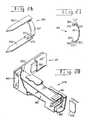
- FIGS. 1-3show that a preferred embodiment of a compression staple I according to the present invention has a pair of legs 13 with sharp front ends 15 and a bridge 17 that interconnects the rear end portions of legs 13.
- Staple 11is fabricated of a surgical grade, bio-compatible metal, such as stainless steel, titanium alloy or other suitable alloy.
- Bridge 17functions not only to hold legs 13 in approximate parallel relationship, but is selected to act as a spring by the flexingof its bow when the legs are spread apart as illustrated by the broken line image of FIGS. 2 and 3. This imparts an inward reacting force between the legs proportional to the degree of their displacement. It will be appreciated that the dimensions, gauge and curvature of bridge 17 are selected such that it can be flexed to a tensioned state that will deliver the compression requirements of the bone fixation to which staple 11 is to be applied.
- legs 13are provided with serrations or barbs 19.
- serrations or barbs 19the size of such serrations or barbs can be advantageously minimized, which minimizes trauma to the bone tissue during their implantation.
- FIG. 4shows a variant 23 of a staple according to the present invention, having legs 25. It is formed from metal rod having suitable strength and spring properties. It is also contemplated under the invention that the curvature of the bridge can take other forms than the single bow shown, and would include, among others a generally V-shape and a shape with double 90 degree bends.
- FIG. 5shows an air-powered staple applicator 29 for applying staple 11, and it includes main body 31, a conventional air piston assembly 33 within body 31, air supply line 35 and a pistol grip and triggerassembly 37 for holding the stapler and for controlling the air-powered operation of the staple head 41, to be described hereinafter.
- the staple head 41features an adjustable staple mount 43 that includes lower head 45 which is a forward extension of body 31, and upper head 47.
- a pair of parallel guide rods 51affixed to lower head 45 and extending upwardly therefrom, slidably engage twin bores 53 in the upper head 47 so as to guide the upper head in vertical motion relative to the lower head 45.
- a screw jack assemblydrives the upper head and includes thrust screw 55 that engages the threaded bore 57 in lower head 45.
- FIG. 7best illustrates the screw jack assembly and shows turn knob 59 that has a socket for receiving a tool such as an Allen wrench for rotating the knob 59.
- FIGS 6 and 7also show a longitudinally extending groove 65 on the lower head 45 and a corresponding parallel groove 63 on the movable upper head 47, these grooves being shaped to cradle the opposing sides of staple legs 13, and the knob can be operated to set the spacing between grooves to allow staple 11, in its initial un-tensioned configuration, to be mounted thereon as illustrated.
- vertically extending gradationsare provided at 67 on a forward surface of body 31, adjacent the movable rear end of upper head 45, so as to gauge the displacement of the staple legs when the invention is operated in a manner to be described below.
- staple applicator 29includes mechanism for driving a staple forwardly from the staple head 41, and includes longitudinally extending striker member 69 that is slidably mounted to grooves 71 and 73 for longitudinal movement, and the rear portion (not shown), is connected to the air piston assembly , and spring means (not shown ) will hold the striker in an initial rearward position as illustrated in FIG. 6.
- Striker member 69has front surface 75 that is adapted, as best shown in FIG 7, to impact the rear legs of the staple bridge 17 when the striker member 69 is propelled to its forward position shown by the phantom lines in FIG 6.
- a staple 11is mounted to the staple mount 43 which is operated to bring the staple to the desired tensioned configuration. Then bone segments are brought together by manual or mechanical manipulation as close as possible and aligned with each other.
- the stapler head 41can then be positioned with its legs straddling the fracture line, and sharp ends 15 adjacent the surfaces of the bone segments.
- the stapler triggercan then be operated to cause the striker to drive the legs of the tensioned staple into the bone segments.
- FIG. 9shows ends 79 and 80 that are adapted to strike respectively the upper and lower rear ends of staple legs 13, of a staple 11 supported in tensioned configuration. It is contemplated under the invention that strikers like striker 69a, with differently spaced ends 79 and 80 can be provided so that different sized staples can be accommodated.
- FIG. 10shows the forward portion 81 of another variant of a power stapler applicator according to the present invention, having a main body 82, an upper staple guide 83 and lower staple guide 85.
- Opposing forward portions 87 of the guidesare separated by a distance allowing it to hold staple 11 in tensioned configuration, and the rearward portions 89 will hold the staple in its initial configuration.
- the open-sided portions 91allow a staple to be loaded by hand unto the staple guides. When the staple is pushed forwardly by hand from portion 89 to portion 87, the divergent portions 93 will cause the spreading apart of the staple legs, and thus a tensioned staple is positioned for ejection.
- a striker member 95has upper and lower edges 97 and 99 slidably engagedin slots 101 and 103 so as to mount the striker member for longitudinal movement.
- the striker front ends 105 and 107will align with and abut the rear ends of a tensioned staple.
- FIGS. 11, 12 and 13show a variant 113 of the invention, whereby percussive force is delivered by hand using a suitable mallet.
- the body 115has a rear portion 117 designed for being struck by a mallet, and staple holder 119 at its front end.
- FIGS. 12 and 13show how the holder 119 includes lower portion 121 that has staple leg-receivinggroove 129, and an adjustable upper part 135 with groove 137.
- FIG. 12best shows how a dove-tail portion 141 of part 135 fits in a complementary slot for guiding vertical movement of part 135.
- Front surfaces 145 and 147 respectively of parts 121 and 135are adapted to abut the rear ends of a staple mounted in grooves 137 and 129.
- a screw 153 for driving the part 135has threads 157 that engage a threaded bore 159 in the movable part 135, and the knob 163 can be engaged by a suitable tool to rotate the screw 153.
- the sharp ends of a tensioned staple 11can advantageously be precisely positioned on the target spots on the bone segments, then the tool end 117 struck with a mallet to implant the staple.
- FIGS. 14 and 15there is shown in FIG. 14 another compressive staple 161 according to the invention that is fabricated of a suitable resilient metal, and features legs 163 and 165 that converge with respect to each other, and interconnect by a bridge 167.
- Staple 161can also be made of a suitable resilient non-metallic bio-absorbable material.
- FIG. 15best shows how legs 163 and 165 each converge at a pre-selected angle ⁇ , with respect to parallel positions that the legs can be resiliently urged in a manner to be described hereinafter. It should be apparent that the material properties of the selected resilient material, the degree of convergence, and the dimensions and form of the staple will be selected by those with ordinary skill in the pertinent art so as to establish a certain force by which the parallel legs are urged to their convergent positions.
- FIG. 16shows one preferred embodiment of a bone-staple applicator 171 having a main body 173 with a rear end 175 adapted for being impacted by a force delivering instrument like a mallet.
- the front end 177is designed to mount a staple 161 in its initial configuration and then move it to, and hold it in, a configuration where its legs are parallel.
- front end 177has an upper jaw 181 that can be adjustably spaced from to a lower jaw 183 using drive-screw mechanism similar to that used for the screw-driven spreadable parts 135 and 121 previously described above and shown in FIGS. 12 and 13.
- FIG. 16shows one preferred embodiment of a bone-staple applicator 171 having a main body 173 with a rear end 175 adapted for being impacted by a force delivering instrument like a mallet.
- the front end 177is designed to mount a staple 161 in its initial configuration and then move it to, and hold it in, a configuration where its legs are parallel.
- FIG. 17shows how the upper jaw 181, and lower jaw 183 are shaped to mount a staple 161, the slots 187 and 189 in the respective jaws being sized to receive the staple bridge 167.
- a recessed portion 191 in the top of the jaw 181is for supporting and stabilizing rearward portions of the upper staple leg 163, and there is a similarly recessed portion on the under-surface of the lower jaw 183 (not shown) for supporting the rearward part 196 of lower staple leg 165.
- the recessed portion 191has a shelf 193 for engaging lower surfaces of leg 163, and opposing edges 195 can hold the staple against lateral movement while the ledge 197 is adapted to abut the rear edge of the staple leg.
- FIG. 18best shows how an untensioned staple 161 is first mounted within the grasp of the opposing recessed portions of the jaws 181 and 183, and it is noted how surfaces 193 and 194 engage inner surfaces 211 and 213 of opposing legs 163 and 165. It should be appreciated how the screw mechanism 217 can be operated to move apart the opposing jaws, causing the opposing legs to be pushed into parallel relationship, as illustrated in FIG. 19. When a staple 161 is thusly mounted on the applicator tool 171, it can be used much the same as the previously described device 113, to apply a tensioned staple 161 to adjoining bone segments. Note that the jaw surfaces 193 and 194 can be appropriately sloped to ensure that the legs will be pushed into parallelism.
- FIGS. 20 and 21show another embodiment of a compression staple according to the present invention, i.e. the staple 261 which is particularly adapted for application by a powered applicator, for example an electrically powered or an air-powered staple applicator such as applicator 271 shown in FIG. 22, to be described.
- the staple 261is fabricated of a suitable resilient metal using conventional metalworking techniques.
- the staple legs 263 and 265extend from the bridge portion 267 and converge at a predetermined angle. It is noted how legs 263 and 265 are wider than the bridge portion 267.
- the inside surfaces of the staple bridge and legsare adapted to slidably engage staple-feeding ramp structure, to be described. Furthermore, FIG.
- FIG. 21best shows how this staple structure provides to one side of the bridge 267, opposing inside surfaces 270 and 274 respectively of legs 263 and 265, which can be advantageously engaged for slidable forward movement of the staple along parallel guide surfaces in the powered staple applicator 271, in a manner to be described.
- the trigger-controlled applicator 271, shown in FIG. 22, except for its forward end,is similar to the above-described applicator 29, and includes a piston assembly 275.
- FIG. 23illustrates how at the forward end of the applicator 271, there is mounted a staple feeder 273 designed to supply and position staples for engagement by the front end 279 of a striker 281 that is connected to the piston assembly 275.
- FIG. 23shows that the feeder 273 includes a housing 285 that is attached to a sidewall of the applicator and which supports a ramp member 287 that has a distal end 289 that is shaped to receive staples 261.
- the walls 291, 292 and 293are shaped so as to be slidably embraced by a number of staples 261 in their relaxed, legs-convergent configurations.
- FIG. 24also illustrates the ramp member 287 and shows how the ramp walls 291 and 292 vary from a convergent orientation at one ramp end to a generally parallel one at the opposite ramp end 294.
- FIG. 23also illustrates that within the feeder housing 285 there is a spring-powered pusher 295, connected to a suitable conventional spring (not shown) for urging the pusher 295 against the rear side edges of a staple 261 mounted on the ramp member 287.
- a spring-powered pusher 295connected to a suitable conventional spring (not shown) for urging the pusher 295 against the rear side edges of a staple 261 mounted on the ramp member 287.
- FIG. 25shows how the innermost end of the ramp member 287 has an end 299 that is spaced from a guidingsurface 301 of applicator wall 304. Surfaces 301 and the opposing upper and lower surfaces 303 and 305 form a channel as FIG. 24 shows, for receiving the striker 281.
- FIG. 25shows in broken lines a tensioned staple 261 in position for being driven by the striker 281. Note that the bridge member 267 is spaced within the above-mentioned channel, clear of the end of the ramp member 287, the staple being supported by virtue of the staple leg surfaces 270 and 274 (FIG. 21) engaging the ramp member. Thus the striker front end 279 is aligned with the rear end of staple bridge portion 267.
- applicator 271In operation of applicator 271 it is supported with its front end in close proximity to the relevant bone segments, and with the pointed ends of the staple appropriately aligned therewith. Pulling the trigger will cause the striker end 279 to impact the staple bridge and propel the staple forwardly as the staple legs are held generally parallel by sliding engagement with the generally parallel surfaces of the ramp member 287 during ejection.
- the strikerwill have a stroke sufficient to cause the legs, in their parallel configuration, to be embedded in the bone tissue.
- the strikerwill return to its initial position rearward of the ramp member. Then spring force will cause another staple to be positioned in the ejectionchannel.
- FIGS. 22 and 23show the feeder 273 connected adjacent the front end 260 of the applicator, it should be appreciated that in some cases it is desirable that the feeder 273 attaches to the applicator 271 at a location spaced a greater distance to the rear of the front 260. In such cases the ramp walls 291 and 292 in the region of wall 301 are elongated forwardly as necessary to provide guide surfaces for the staple, and the stroke of the striker 281 is increased accordingly.
- FIGS. 26 and 27illustrate yet another variant 361 of the compression staple 11 described above (FIG. 1), and has generally parallel legs 363 and 365 and resilient bridge 367.
- This configurationprovides opposing surfaces 370 and 374, best shown in FIG. 27, that are adapted to engage parallel guide surfaces when the staple 361 is propelled from a powered staple applicator 371; to be described.
- FIG. 27the tensioned configuration of staple 361 in shown in broken lines.
- FIG. 28shows a feeder 373 which is constructed similarly to the above-described feeder 273, except that the ramp member 387 is adapted to handle the staple 361.
- the ramp walls 391 and 392provide parallel surfaces for engaginginside surfaces of the staple legs and the wall 393 slidably abuts the wall 393.
- the distal end of the ramp 387receives staples 361 in their untensioned condition, and the walls 391 and 392 gradually diverge from each other such that at the other end 395 of the ramp, a staple 361 will be supported in a legs-parallel tensioned configuration.
- a spring-powered pusher 399is adapted to urge a number of nested staples 361 towards the end 395 of the ramp.
- the ramp end 395is spaced a predetermined distance from the guide surface 401 and provides surfaces that engage the opposing surfaces 370 and 374 of staple 361. Thus the rear of a tensioned staple can be struck by the striker 397 and ejected from the applicator.
Landscapes
- Health & Medical Sciences (AREA)
- Surgery (AREA)
- Life Sciences & Earth Sciences (AREA)
- General Health & Medical Sciences (AREA)
- Veterinary Medicine (AREA)
- Rheumatology (AREA)
- Engineering & Computer Science (AREA)
- Biomedical Technology (AREA)
- Heart & Thoracic Surgery (AREA)
- Medical Informatics (AREA)
- Molecular Biology (AREA)
- Animal Behavior & Ethology (AREA)
- Orthopedic Medicine & Surgery (AREA)
- Public Health (AREA)
- Nuclear Medicine, Radiotherapy & Molecular Imaging (AREA)
- Surgical Instruments (AREA)
- Orthopedics, Nursing, And Contraception (AREA)
- Dairy Products (AREA)
- Confectionery (AREA)
- Gripping Jigs, Holding Jigs, And Positioning Jigs (AREA)
- Paper (AREA)
- Load-Engaging Elements For Cranes (AREA)
- Pharmaceuticals Containing Other Organic And Inorganic Compounds (AREA)
- Materials For Medical Uses (AREA)
Abstract
Description
- The present invention relates to devices and techniques for securing bone segments across a fracture site, and more particularly relates to a bone stapling method and apparatus for achieving compression between segments.
- In treating a bone fracture it is common practice to fasten one bone segment to the other so as to stabilize and immobilize them for the duration of the bone consolidation process. Thus there is the technique of internal fixation or direct mechanical fastening of the bone segments.
- Traditionally, fixation has been accomplished by variety of apparatus and techniques, the more common involving the use of metallic fastening devices such as screws, connector plates (secured to the bone by screws), pins and clips. These methods invariably involve the drilling of screw holes in the bone and the use of related equipment such as drill hole templates.
- Conventional U-shaped clips have also been used, the clip legs being installed one each in holes in the opposing bone segments. The rigid structure of such clips, like the other fixation devices mentioned above, provide rigid immobilization of the fracture zone. Such devices also served to maintain the distance between segments, which was found however, among other things, to hinder compression induced by contractions of skeletal muscles in some cases, and prevent the establishment of compressive force between the bone segments which is favorable to bone consolidation or knitting. In this regard the concept of creating dynamic compressive force across an osteotomy or bone fracture site has become well recognized as a technique to promote primary bone healing, i.e. consolidation that is faster and of better quality.
- Thus there has evolved a number of fastening devices such as clips and the like, designed to deliver compression. Accordingly in
U.S. patent 3,939,294 there is provided a clasp or clip of spring material having a pair of spaced-apart, inwardly inclined legs connected by a Z-shaped upper portion. Sloped holes are drilled in adjoining bone segments and tools are used to manipulate and install one leg, and then the other leg is pulled toward the other hole, spreading the Z-shaped elastic portion, and then inserted in the other hole. Unfortunately this method requires the drilling of specially sloped holes, involves multiple steps and is time-consuming, and like the conventional rigid fastening techniques, requires relatively large surgical opening. Also, the manual installation of the clip using hemostats and the like is difficult, requires meticulous skill and handling. - In
U.S. patent 4,838,254 the legs of a pair of metallic clips are inserted in pairs of specially angled bores in respective opposing bone segments The exposed tops of the two installed clips then serve as fastening heads for a spring that is connected between the clips. - In
U.S. patent 4,841,960 the disclosed "compression" clip is essentially a clip with opposing legs that are installed in pre-drilled holes and features a crimpable web that joins the top ends of the legs. A crimping tool is used to crimp the web in an effort to set up compression between the embedded legs. - U. S. patent No.
4,852,558 also requires manual installation of separate legs in pre-drilled holes, the tops of the install legs then being interconnected with a ratchet mechanism which must be operated to draw the legs together. This design appears inherently limited regarding adjustability and maintenance of constant pressure. In U. S. patent No.5,660,188 the two legs of a clip must also be installed in pre-drilled holes. The clip has a bridge of two side -by -side crimpable elements, and the jaws of a crimping tool must be used on the embedded clip to deformingly spread apart these elements, causing the legs to draw to each other. The foregoing techniques involving crimpable clips all appear to be imprecise in setting up suitable compressive forces, require hole drilling and related problems, and do not lend themselves to minimizing the size of the surgical opening. - In view of the limitations of the afore-mentioned methods, stapling has been looked to as a potentially quick and effective way for fastening bone segments, and as a way to produce compression. Thus in
U.S. patents No. 5,053,038 and5,662,655 "compression" staples are applied to the bone by a powered stapler. These staples have legs shaped with beveled ends and /or have divergent legs that will be forced apart from each other during implantation, which flexes springy upper parts of the legs thereby tending to set up compression. Unfortunately there is concern for trauma to the bone due to driving of the compound-shaped legs into the bone mass, and there is little apparent precision in establishing the desired compressive forces. - In view of the foregoing it is a general object of the present invention to provide an improved method and for interosseous fastening.
- A more particular object is to provide quick and simple, yet effective method for fastening bone segments with compressive force between opposing bone ends.
- Another object to provide such a method that minimizes the size of the required surgical opening and associated trauma.
- A further object to provide a method of bone stapling that minimizes trauma to the bone tissue during implantation of the staple legs.
- Yet another object is to provide a method for stapling that maximizes the capability of establishing a dynamic compression level that is optimal for enhanced osseous healing.
- A still further object is to provide simple, effective bone fixation technique that is relatively easy to learn and practice.
- Another object is to provide for compression fixation in applications where other techniques would not work or would not deliver compression. For example, conventional fastening techniques for handling a "Jones" fracture, i.e. one that is transverse to the longitudinal extent of the bone segment, is difficult to address using conventional fastening techniques, however the present invention is particularly suitable to provide fastening for such fractures.
- Still another object is to provide stapling apparatus and method in which there is enhanced selection capability regarding the level of the compressive forces to be imparted.
- There are a number of advantages in exterior bone fixation techniques, where surgical incisions are not required and fasteners are applied through the skin; and thus it is yet another object of the invention to provide a bone stapling method that lends itself well to exterior bone fixation.
- These and other objects of the present invention are achievable by way of the present invention of a bone stapling method and apparatus that uses a generally U-shaped staple having pair of spaced apart legs with sharp free ends and proximal ends interconnected by bridge that has at least one resilient curved portion, whereby spreading apart of the parallel legs lessens the curvature of the curved portions which brings the staple to a tensioned configuration in which one leg is resiliently urged towards the other. In a preferred embodiment it is seen that the bridge portion comprises a single bowed spring element, the curvature of which lies in a plane normal to the axes of the staple legs.
- The novel fastening method involves first positioning the fractured ends of a first and a second bone segment in proximate, face-to-face relationship. The next step involves spreading apart the staple legs by a certain amount and holding the staple in the resultant tensioned configuration. The extent to which the staple legs are separated can be varied in one preferred embodiment of the invention, the induced compressive forces between the legs being proportional to the amount of displacement of the legs as the bowed portion is moved through range of motion in which elastic behavior is exhibited. In this regard it should be evident that herein lies one of the advantages of the present invention, i.e. the capability of selecting the optimal compressive force for an application by spreading apart the staple legs by a predetermined amount.
- Next, as the staple is held in its tensioned configuration, it is positioned with it sharp ends forward and aligned respectively with surfaces of one bone segments and the other. Finally the positioned staple, while maintained in its tensioned configuration, is driven into the bone by percussive force, such quick application being provided by a conventional air-powered striker of a stapler according to the present invention, or by a manually stuck staple applicator according to the invention. The embedded staple legs will cause the opposing bone faces to be pressed into each other with a predetermined amount of force.
- Such stapling method lends itself advantageously to a staple with a relatively narrow profile, wherein apparatus according to the present invention include a staple applicator having within its housing means for supporting the staple and guiding its movement with legs pointed ends forwardly disposed, and adapted to receive the staple in its initial un-tensioned configuration engaging its legs and spreading them apart by certain amount and holding the staple in its tensioned configuration adjacent the front end of the housing, for ejection therefrom. One embodiment, of several, uses opposing first and second grooves for engaging the staple legs and means for adjustably moving one groove from the other. Another embodiment employs grooves that diverge to spread the staple legs as a staple is advanced there-along. Ejection means mounted for longitudinal movement in the housing has a front end adapted to strike the rear of the tensioned staple with percussive force which is provided by air power or electrical power in preferred embodiments.
- The invention also includes a staple applicator that is adapted for being manually driven.
- Another related bone stapling method for compressively securing adjoining bone segments uses a resilient metallic staple that has legs with an initial convergent configuration with respect to each other, and the legs are resiliently extendible into parallel relationship, in which configuration a predetermined amount of spring force will urge the legs towards their initial convergent orientation. This method includes holding the normally convergent staple in its legs-parallel configuration, positioning the so-tensioned staple with its sharp ends alignedrespectively with adjacent bone surfaces; and then driving and embedding the legs of the tensioned staple in the bone segments and releasing the embedded staple, whereby the bone segments are joined, and opposing surfaces of the bone segments are caused to be pressed into engagement with each other with a certain amount of compressive force.
- An applicator or tool for such a staple includes staple-engaging means on the front end of the applicator body. Opposing jaws support the staple in a pointed-ends forward position against lateral and rearward movement, and engage inside surfaces of the convergent legs, the jaws being adapted for adjustable movement apart to cause the legs to rotate to a generally parallel orientation. Thus supported on the front end of the tool, the staple can be aligned with the bone segments, and the rear end of the tool stuck with a percussive force to cause the staple legs to be embedded into the bone segments.
- Another applicator according to the present invention has a trigger-controlled air-powered staple-driving mechanism, and has a staple feeding mechanism including ramp means that is shaped to receive and support a staple in its initial configuration on one end of said ramp means , the configuration of the ramp means gradually changing to a shape that will hold the staple with its legs generally parallel with each other. Thus the staple can be slidably pushed along the ramp means in a lateral direction, i.e. normal to the plane in which the staple legs and bridge portion lie, to bring it to a terminal position along the ramp means, in which position the rear of the tensioned staple can be struck by the front end of a powered striker.
- FIG. 1 is perspective view of a preferred embodiment of a compression staple according to the present invention;
- FIG. 2 is top plan view of the embodiment of the staple of FIG. 1;
- FIG. 3 is a rear end elevational view of the staple of FIG. 1;
- FIG. 4 is a perspective view of variant of a staple according to the present invention;
- FIG. 5 is an elevational view of staple applicator according to the present invention, with parts broken away for the sake of clarity;
- FIG. 6 is a partial, perspective enlarged view of the front end of the staple applicator of FIG 5;
- FIG. 7 is a sectional view taken long the line 7-7 of FIG. 6;
- FIG. 8 is sectional view taken long the line 8-8 of FIG. 6;
- FIG. 9 is an enlarged, partial perspective view of the front portion of a variant of a staple applicator according to the present invention;
- FIG. 10 is an enlarged, partial perspective view of the front portion of another variant of a staple applicator according to the present invention;
- FIG. 11 is a top plan view of a manually powered stapler according to the present invention;
- FIG. 12 is a partial, enlarged perspective view of the front portion of the staple applicator of FIG 11;
- FIG.13 is a sectional view taken along the line 13-13 of FIG. 12;
- FIG. 14 is a perspective view of another variant of a compressive staple according to the present invention, wherein the staple legs have a convergent orientation with respect to each other;
- FIG. 15 is a side elevational view of the staple of FIG. 14;
- FIG. 16 is a top plan view of a staple applicator according to the present invention;
- FIG. 17 is an enlarged, partial perspective view of the front end of the applicator of FIG 16;
- FIG. 18 is an enlarged partial, side elevational, partially sectional view illustrating the mounting of a staple on the front end of the staple applicator of FIG. 16;
- FIG. 19 is a view similar to FIG. 18 showing a staple supported with legs parallel;
- FIG. 20 is a perspective view of a convergent-legged staple that is adapted to be fed to a powered staple applicator;
- FIG. 21 is a rear elevational view of the staple of FIG. 20;
- FIG. 22 is a side elevational view of another powered applicator according to the invention;
- FIG. 23 is a perspective illustration showing means for feeding staples to the staple-driving means of the powered staple applicator shown in FIG. 22;
- FIG. 24 is a partial, enlarged, partial sectional side view of staple-delivering ramp member of the applicator shown in FIG. 22;
- FIG. 25 is a schematic illustration of the staple-striking region of the staple feeding means of FIG. 23;
- FIG. 26 is a perspective view of another variant of another compression staple similar to the staple of FIG. 1, and adapted for use with a staple-feeding magazine or cartridge;
- FIG. 27 is a front end elevational view of the staple of FIG. 26; and
- FIG. 28 is a partial sectional perspective view, with parts broken away for the sake of clarity, illustrating a magazine or cartridge for feeding the staple of FIG. 26 to a powered staple applicator.
- Referring now the drawings, FIGS. 1-3 show that a preferred embodiment of a compression staple I according to the present invention has a pair of
legs 13 with sharp front ends 15 and abridge 17 that interconnects the rear end portions oflegs 13.Staple 11 is fabricated of a surgical grade, bio-compatible metal, such as stainless steel, titanium alloy or other suitable alloy.Bridge 17 functions not only to holdlegs 13 in approximate parallel relationship, but is selected to act as a spring by the flexingof its bow when the legs are spread apart as illustrated by the broken line image of FIGS. 2 and 3. This imparts an inward reacting force between the legs proportional to the degree of their displacement. It will be appreciated that the dimensions, gauge and curvature ofbridge 17 are selected such that it can be flexed to a tensioned state that will deliver the compression requirements of the bone fixation to whichstaple 11 is to be applied. - It is preferred that the opposing inside surfaces of
legs 13 are provided with serrations orbarbs 19. In this regard it is noted that, inasmuch as the insides oflegs 13 will be pressed against bone mass when they are embedded in a manner to be described, the size of such serrations or barbs can be advantageously minimized, which minimizes trauma to the bone tissue during their implantation. - It will be evident that there can be several variations of compression staples according to the principles of the invention. For example, staple legs can have various cross sectional configurations, including diamond-shaped, square, triangular and rectangular. FIG. 4 shows a
variant 23 of a staple according to the present invention, havinglegs 25. It is formed from metal rod having suitable strength and spring properties. It is also contemplated under the invention that the curvature of the bridge can take other forms than the single bow shown, and would include, among others a generally V-shape and a shape with double 90 degree bends. - FIG. 5 shows an air-powered
staple applicator 29 for applyingstaple 11, and it includesmain body 31, a conventionalair piston assembly 33 withinbody 31,air supply line 35 and a pistol grip andtriggerassembly 37 for holding the stapler and for controlling the air-powered operation of thestaple head 41, to be described hereinafter. - As FIG. 6 illustrates, the
staple head 41 features anadjustable staple mount 43 that includeslower head 45 which is a forward extension ofbody 31, andupper head 47. A pair ofparallel guide rods 51, affixed tolower head 45 and extending upwardly therefrom, slidably engage twin bores 53 in theupper head 47 so as to guide the upper head in vertical motion relative to thelower head 45. A screw jack assembly drives the upper head and includes thrustscrew 55 that engages the threaded bore 57 inlower head 45. FIG. 7 best illustrates the screw jack assembly and shows turnknob 59 that has a socket for receiving a tool such as an Allen wrench for rotating theknob 59. FIGS 6 and 7 also show alongitudinally extending groove 65 on thelower head 45 and a corresponding parallel groove 63 on the movableupper head 47, these grooves being shaped to cradle the opposing sides ofstaple legs 13, and the knob can be operated to set the spacing between grooves to allowstaple 11, in its initial un-tensioned configuration, to be mounted thereon as illustrated. - In a preferred embodiment, vertically extending gradations are provided at 67 on a forward surface of
body 31, adjacent the movable rear end ofupper head 45, so as to gauge the displacement of the staple legs when the invention is operated in a manner to be described below. - As FIGS. 6 and 7 and 8 also show,
staple applicator 29 includes mechanism for driving a staple forwardly from thestaple head 41, and includes longitudinally extendingstriker member 69 that is slidably mounted togrooves Striker member 69 hasfront surface 75 that is adapted, as best shown in FIG 7, to impact the rear legs of thestaple bridge 17 when thestriker member 69 is propelled to its forward position shown by the phantom lines in FIG 6. - In the operation of
staple applicator 29 for osteosynthesis, astaple 11 is mounted to thestaple mount 43 which is operated to bring the staple to the desired tensioned configuration. Then bone segments are brought together by manual or mechanical manipulation as close as possible and aligned with each other. Thestapler head 41 can then be positioned with its legs straddling the fracture line, and sharp ends 15 adjacent the surfaces of the bone segments. The stapler trigger can then be operated to cause the striker to drive the legs of the tensioned staple into the bone segments. - There is a variant of a staple applicator accordingto the invention that is identical to the embodiment of FIGS 6 and 7 , except that it has a striker member 69a is designed to engage the rear ends of
staple legs 13 instead of the rear edge of thestaple bridge 17. Thus the sectional view of FIG. 9 shows ends 79 and 80 that are adapted to strike respectively the upper and lower rear ends ofstaple legs 13, of a staple 11 supported in tensioned configuration. It is contemplated under the invention that strikers like striker 69a, with differently spaced ends 79 and 80 can be provided so that different sized staples can be accommodated.. - FIG. 10 shows the
forward portion 81 of another variant of a power stapler applicator according to the present invention, having amain body 82, anupper staple guide 83 andlower staple guide 85. Opposing forwardportions 87 of the guides are separated by a distance allowing it to holdstaple 11 in tensioned configuration, and therearward portions 89 will hold the staple in its initial configuration. The open-sided portions 91 allow a staple to be loaded by hand unto the staple guides. When the staple is pushed forwardly by hand fromportion 89 toportion 87, thedivergent portions 93 will cause the spreading apart of the staple legs, and thus a tensioned staple is positioned for ejection. - A
striker member 95 has upper andlower edges engagedin slots - FIGS. 11, 12 and 13 show a
variant 113 of the invention, whereby percussive force is delivered by hand using a suitable mallet. Here thebody 115 has arear portion 117 designed for being struck by a mallet, andstaple holder 119 at its front end. FIGS. 12 and 13 show how theholder 119 includeslower portion 121 that has staple leg-receivinggroove 129, and an adjustableupper part 135 withgroove 137. FIG. 12 best shows how a dove-tail portion 141 ofpart 135 fits in a complementary slot for guiding vertical movement ofpart 135. Front surfaces 145 and 147 respectively ofparts grooves screw 153 for driving thepart 135 has threads 157 that engage a threaded bore 159 in themovable part 135, and theknob 163 can be engaged by a suitable tool to rotate thescrew 153. - In using
tool 113 the sharp ends of a tensionedstaple 11 can advantageously be precisely positioned on the target spots on the bone segments, then thetool end 117 struck with a mallet to implant the staple. - Referring now to FIGS. 14 and 15 there is shown in FIG. 14 another
compressive staple 161 according to the invention that is fabricated of a suitable resilient metal, and featureslegs bridge 167.Staple 161 can also be made of a suitable resilient non-metallic bio-absorbable material. - FIG. 15 best shows how
legs - FIG. 16 shows one preferred embodiment of a bone-
staple applicator 171 having amain body 173 with arear end 175 adapted for being impacted by a force delivering instrument like a mallet. Thefront end 177 is designed to mount a staple 161 in its initial configuration and then move it to, and hold it in, a configuration where its legs are parallel. Thus it is seen in FIG. 17 thatfront end 177 has anupper jaw 181 that can be adjustably spaced from to alower jaw 183 using drive-screw mechanism similar to that used for the screw-drivenspreadable parts upper jaw 181, andlower jaw 183 are shaped to mount astaple 161, theslots staple bridge 167. A recessedportion 191 in the top of thejaw 181 is for supporting and stabilizing rearward portions of the upperstaple leg 163, and there is a similarly recessed portion on the under-surface of the lower jaw 183 (not shown) for supporting therearward part 196 of lowerstaple leg 165. The recessedportion 191 has ashelf 193 for engaging lower surfaces ofleg 163, and opposingedges 195 can hold the staple against lateral movement while theledge 197 is adapted to abut the rear edge of the staple leg. - FIG. 18 best shows how an
untensioned staple 161 is first mounted within the grasp of the opposing recessed portions of thejaws inner surfaces 211 and 213 of opposinglegs staple 161 is thusly mounted on theapplicator tool 171, it can be used much the same as the previously describeddevice 113, to apply atensioned staple 161 to adjoining bone segments. Note that the jaw surfaces 193 and 194 can be appropriately sloped to ensure that the legs will be pushed into parallelism. - FIGS. 20 and 21 show another embodiment of a compression staple according to the present invention, i.e. the staple 261 which is particularly adapted for application by a powered applicator, for example an electrically powered or an air-powered staple applicator such as
applicator 271 shown in FIG. 22, to be described. Like the previously describedstaple 161, thestaple 261 is fabricated of a suitable resilient metal using conventional metalworking techniques. Thestaple legs bridge portion 267 and converge at a predetermined angle. It is noted howlegs bridge portion 267. The inside surfaces of the staple bridge and legs are adapted to slidably engage staple-feeding ramp structure, to be described. Furthermore, FIG. 21 best shows how this staple structure provides to one side of thebridge 267, opposing insidesurfaces legs staple applicator 271, in a manner to be described. - The trigger-controlled
applicator 271, shown in FIG. 22, except for its forward end, is similar to the above-describedapplicator 29, and includes apiston assembly 275. FIG. 23 illustrates how at the forward end of theapplicator 271, there is mounted astaple feeder 273 designed to supply and position staples for engagement by thefront end 279 of astriker 281 that is connected to thepiston assembly 275. - FIG. 23 shows that the
feeder 273 includes ahousing 285 that is attached to a sidewall of the applicator and which supports aramp member 287 that has adistal end 289 that is shaped to receivestaples 261. Thewalls staples 261 in their relaxed, legs-convergent configurations. FIG. 24 also illustrates theramp member 287 and shows how theramp walls opposite ramp end 294. FIG. 23 also illustrates that within thefeeder housing 285 there is a spring-poweredpusher 295, connected to a suitable conventional spring (not shown) for urging thepusher 295 against the rear side edges of a staple 261 mounted on theramp member 287. Thus it can be appreciated how astaple 261, or several side-by-side staples 261, can be slidably pushed towards theend 294 of the ramp member. - The enlarged view of FIG. 25 shows how the innermost end of the
ramp member 287 has anend 299 that is spaced from aguidingsurface 301 of applicator wall 304.Surfaces 301 and the opposing upper andlower surfaces 303 and 305 form a channel as FIG. 24 shows, for receiving thestriker 281. FIG. 25 shows in broken lines atensioned staple 261 in position for being driven by thestriker 281. Note that thebridge member 267 is spaced within the above-mentioned channel, clear of the end of theramp member 287, the staple being supported by virtue of the staple leg surfaces 270 and 274 (FIG. 21) engaging the ramp member. Thus the strikerfront end 279 is aligned with the rear end ofstaple bridge portion 267. - In operation of
applicator 271 it is supported with its front end in close proximity to the relevant bone segments, and with the pointed ends of the staple appropriately aligned therewith. Pulling the trigger will cause thestriker end 279 to impact the staple bridge and propel the staple forwardly as the staple legs are held generally parallel by sliding engagement with the generally parallel surfaces of theramp member 287 during ejection. - The striker will have a stroke sufficient to cause the legs, in their parallel configuration, to be embedded in the bone tissue. The striker will return to its initial position rearward of the ramp member. Then spring force will cause another staple to be positioned in the ejectionchannel.
- Although FIGS. 22 and 23 show the
feeder 273 connected adjacent thefront end 260 of the applicator, it should be appreciated that in some cases it is desirable that thefeeder 273 attaches to theapplicator 271 at a location spaced a greater distance to the rear of the front 260. In such cases theramp walls wall 301 are elongated forwardly as necessary to provide guide surfaces for the staple, and the stroke of thestriker 281 is increased accordingly. - FIGS. 26 and 27 illustrate yet another
variant 361 of thecompression staple 11 described above (FIG. 1), and has generallyparallel legs resilient bridge 367. This configuration provides opposingsurfaces staple 361 is propelled from a poweredstaple applicator 371; to be described. In FIG. 27 the tensioned configuration ofstaple 361 in shown in broken lines. - FIG. 28 shows a
feeder 373 which is constructed similarly to the above-describedfeeder 273, except that theramp member 387 is adapted to handle thestaple 361. Thus theramp walls wall 393 slidably abuts thewall 393. - The distal end of the
ramp 387 receivesstaples 361 in their untensioned condition, and thewalls staple 361 will be supported in a legs-parallel tensioned configuration. A spring-poweredpusher 399 is adapted to urge a number of nestedstaples 361 towards the end 395 of the ramp. - The ramp end 395 is spaced a predetermined distance from the
guide surface 401 and provides surfaces that engage the opposingsurfaces staple 361. Thus the rear of a tensioned staple can be struck by thestriker 397 and ejected from the applicator. - While particular embodiments of the invention have been described, it should be understood that the invention is not limited thereto, and includes other variants and modifications that will readily occur to those persons of ordinary skill in the art, given the benefit of this disclosure. Thus it is intended that the invention be given its full scope and breath as defined in the claims which follow.
Claims (14)
- A compression staple for fastening a first bone segment to a second bone segment, said staple comprised of a resilient material and having a generally U-shaped configuration, and comprising:a) first and second spaced-apart longitudinally extending legs with sharp free ends and proximal ends;b) a bridge portion interconnecting the proximal ends of said legs; and wherein said legs have a convergent orientation, one to the other, and said legs are adapted to be resiliently held in a parallel orientation wherein said legs are urged towards their initial convergent orientation with a predetermined force.
- A staple as defined in claim 1 wherein said legs are wider than said bridge portion.
- A staple as defined in claim 1 or 2 wherein said bridge portion lies to one side of said legs and the other sides of said legs have opposing generally flat surfaces.
- Bone staple applicator for a generally U-shaped staple having a first and a second spaced apart legs with sharp free ends and proximal ends interconnected by a bridge portion, and an initial configuration where said legs are convergently oriented, and said staple capable of a tensioned configuration in which said legs are held in parallel relationship, said staple applicator including:a) an elongate body with a front end and a rear end, and including :i) means on said body front end for supporting said staple against rearward and lateral movement with the sharp ends of its legs forwardly disposed, and adapted for engaging opposing portions of said legs and moving said legs into parallel relationship.
- A bone staple applicator as defined in claim 4 wherein said tool body has a handle portion, and said rear end is adapted for being struck a percussive blow.
- Bone staple applicator for a generally U-shaped staple having a first and a second spaced-apart legs with sharp free ends and proximal ends interconnected by a bridge portion, and wherein said legs have an initial convergent orientation one to the other, and said staple capable of a tensioned configuration in which said legs are held in parallel relationship, said parallel legs urged towards their initial convergent orientation by certain spring force; said staple applicator including:a) a longitudinally extending body with a front end and a rear end, and including:i) means on said body front end for supporting said staple in its tensioned configuration with the sharp ends of its legs forwardly disposed, and adapted for engaging opposing inside surfaces of said legs and for guiding longitudinal forward movement of said tensioned staple;ii) means for moving said staple from its initial orientation to its tensioned configuration, and for delivering said staple to said staple support means; andiii) means mounted to said body for striking the rear end of said tensioned staple with percussive force for driving said tensioned staple forwardly from said staple- supporting means.
- Applicator as defined in claim 6 wherein said striking means includes an elongate striker mounted to said body for longitudinal movement, and having a front end adapted for impacting the rearward end portion of said staple.
- Applicator as defined in claim 6 wherein said means for supporting said staple includes opposing first and second supports adapted for engaging respectively the first and second legs of said staple, and mounted for being adjustably spread apart so as to move said legs to a parallel orientation.
- Applicator as defined in claim 8 wherein said means for adjustably moving said supports comprises drive means, engaging said first and second supports.
- Applicator defined in claim 9 wherein said drive means includes drive screw mechanism.
- Applicator as defined in claim 6 wherein said means for moving said staple and delivering said staple includes elongate ramp means adapted for slidably engaging inner surfaces of said staple legs and bridge portion, and having surfaces configured so that said legs are pushed from their divergent orientation to parallel orientation by virtue of moving said staple in a direction along said ramp in a direction normal to the plane in which said legs and bridge portion lie; and means for pushing said staple along said ramp means.
- A bone staple applicator for a generally U-shaped staple having a pair of generally parallel spaced apart legs with sharp free ends and proximal ends interconnected by a bridge element that has at least one resilient arcuate portion, and said staple having a rear end portion and an initial configuration and capable of a tensioned configuration in which said legs are spread apart from each other by a certain amount whereby the curvature of said resilient arcuate portion is lessened and said spaced-apart legs urged towards each other by certain spring force; said applicator including:a) an elongate body with a front end and a rear end, and including:i) means on said body for supporting said tensioned staple with the sharp ends of its legs forwardly disposed, for guiding said staple in longitudinal movement;ii) means mounted to said body for striking the rear end of said tensioned staple with percussive force for driving said tensioned staple forwardly along said staple guiding means; andiii) ramp means having a proximal and a distal end, and adapted for being slidably embraced by inner surfaces of said staple and for guiding slidable movement of said staple therealong in a direction normal to the plane in which the legs and bridge element of said staple lie, whereby movement of said staple from the distal to the proximal end of said ramp means will urge said staple to its tensioned configuration.
- An applicator as defined in claim 12 including means for biasing a staple along said ramp means towards the proximal end of said ramp means.
- An applicator as defined in claim 12 wherein said ramp means is adapted to be removably attached to said applicator body.
Applications Claiming Priority (2)
| Application Number | Priority Date | Filing Date | Title |
|---|---|---|---|
| US09/299,285US6059787A (en) | 1999-04-26 | 1999-04-26 | Compression bone staple apparatus and method |
| EP00926301AEP1179994B1 (en) | 1999-04-26 | 2000-04-24 | Compression bone staple, apparatus and method |
Related Parent Applications (1)
| Application Number | Title | Priority Date | Filing Date |
|---|---|---|---|
| EP00926301ADivisionEP1179994B1 (en) | 1999-04-26 | 2000-04-24 | Compression bone staple, apparatus and method |
Publications (2)
| Publication Number | Publication Date |
|---|---|
| EP1772107A1true EP1772107A1 (en) | 2007-04-11 |
| EP1772107B1 EP1772107B1 (en) | 2009-12-23 |
Family
ID=23154131
Family Applications (2)
| Application Number | Title | Priority Date | Filing Date |
|---|---|---|---|
| EP00926301AExpired - LifetimeEP1179994B1 (en) | 1999-04-26 | 2000-04-24 | Compression bone staple, apparatus and method |
| EP06125312AExpired - LifetimeEP1772107B1 (en) | 1999-04-26 | 2000-04-24 | Compression bone staple and apparatus |
Family Applications Before (1)
| Application Number | Title | Priority Date | Filing Date |
|---|---|---|---|
| EP00926301AExpired - LifetimeEP1179994B1 (en) | 1999-04-26 | 2000-04-24 | Compression bone staple, apparatus and method |
Country Status (9)
| Country | Link |
|---|---|
| US (5) | US6059787A (en) |
| EP (2) | EP1179994B1 (en) |
| JP (1) | JP4256074B2 (en) |
| AT (2) | ATE347321T1 (en) |
| AU (1) | AU775585B2 (en) |
| CA (2) | CA2368248C (en) |
| DE (2) | DE60043596D1 (en) |
| ES (2) | ES2277836T3 (en) |
| WO (1) | WO2000064361A1 (en) |
Cited By (5)
| Publication number | Priority date | Publication date | Assignee | Title |
|---|---|---|---|---|
| EP3145422A4 (en)* | 2014-05-21 | 2018-01-17 | Nextremity Solutions, Inc. | Staples and staple delivery and drill guides |
| US10987101B2 (en) | 2017-12-22 | 2021-04-27 | Ortho Solutions Holdings Limited | Superelastic bone compression staple |
| US11000323B2 (en) | 2018-06-01 | 2021-05-11 | Ortho Solutions Holdings Limited | Claw foot bone plate and plate inserter system with fixed and active compression, and method for its use |
| US11000281B2 (en) | 2017-12-22 | 2021-05-11 | Ortho Solutions Holdings Limited | Bone staple inserter |
| KR102309725B1 (en)* | 2020-12-31 | 2021-10-06 | 순천향대학교 산학협력단 | Clip Applier for fracture repair |
Families Citing this family (147)
| Publication number | Priority date | Publication date | Assignee | Title |
|---|---|---|---|---|
| US6059787A (en)* | 1999-04-26 | 2000-05-09 | Allen; Drew | Compression bone staple apparatus and method |
| FR2897259B1 (en) | 2006-02-15 | 2008-05-09 | Ldr Medical Soc Par Actions Si | INTERSOMATIC TRANSFORAMINAL CAGE WITH INTERBREBAL FUSION GRAFT AND CAGE IMPLANTATION INSTRUMENT |
| FR2811540B1 (en)* | 2000-07-12 | 2003-04-25 | Spine Next Sa | IMPORTING INTERVERTEBRAL IMPLANT |
| IL138320A (en)* | 2000-09-07 | 2005-11-20 | Niti Alloys Tech Ltd | Staples for bone fixation |
| JP2002159500A (en)* | 2000-11-28 | 2002-06-04 | Koseki Ika Kk | Ligament fixing system |
| US7344539B2 (en)* | 2001-03-30 | 2008-03-18 | Depuy Acromed, Inc. | Intervertebral connection system |
| FR2827156B1 (en)* | 2001-07-13 | 2003-11-14 | Ldr Medical | VERTEBRAL CAGE DEVICE WITH MODULAR FASTENING |
| AU2002349962B2 (en)* | 2001-10-19 | 2006-04-06 | Baylor College Of Medicine | Bone compression devices and systems and methods of contouring and using same |
| US6966911B2 (en)* | 2002-01-22 | 2005-11-22 | Jorge Abel Groiso | Bone staple and methods for correcting bone deficiencies by controllably suppressing and/or inducing the growth of the epiphyseal plate |
| WO2003088846A1 (en)* | 2002-04-22 | 2003-10-30 | Tyco Healthcare Group, Lp | Tack and tack applier |
| US6908467B2 (en)* | 2002-05-14 | 2005-06-21 | The University Of Hong Kong | Supreme distracter |
| ITMI20021817A1 (en)* | 2002-08-09 | 2004-02-10 | Gianni Ponte | STERBUS STRAW STITCH. |
| US6849079B1 (en)* | 2002-12-10 | 2005-02-01 | Joseph W. Blake, III | Clip detent spring for repeating multi-clip applier |
| US7343920B2 (en)* | 2002-12-20 | 2008-03-18 | Toby E Bruce | Connective tissue repair system |
| AU2003240340A1 (en)* | 2003-06-11 | 2005-01-04 | Synthes Gmbh | Bone clamp |
| US7556647B2 (en)* | 2003-10-08 | 2009-07-07 | Arbor Surgical Technologies, Inc. | Attachment device and methods of using the same |
| US7297146B2 (en)* | 2004-01-30 | 2007-11-20 | Warsaw Orthopedic, Inc. | Orthopedic distraction implants and techniques |
| EP2113227B1 (en) | 2004-02-04 | 2015-07-29 | LDR Medical | Intervertebral disc prosthesis |
| FR2874166B1 (en)* | 2004-08-11 | 2012-03-30 | Surge Foot | SURGICAL CLIP |
| US20060180633A1 (en)* | 2005-02-17 | 2006-08-17 | Tyco Healthcare Group, Lp | Surgical staple |
| US8679154B2 (en)* | 2007-01-12 | 2014-03-25 | Ethicon Endo-Surgery, Inc. | Adjustable compression staple and method for stapling with adjustable compression |
| EP1764042A3 (en)* | 2005-09-12 | 2009-08-26 | Arthrex, Inc. | Compression staple |
| FR2891135B1 (en) | 2005-09-23 | 2008-09-12 | Ldr Medical Sarl | INTERVERTEBRAL DISC PROSTHESIS |
| US20070142838A1 (en)* | 2005-12-19 | 2007-06-21 | Christopher Jordan | Surgical suture staple and attachment device for securing a soft tissue to a bone |
| DE202006002182U1 (en)* | 2006-02-11 | 2006-04-20 | Shano, Majid, Dr. | Implant for osteosynthesis |
| US8021389B2 (en)* | 2006-05-17 | 2011-09-20 | Warsaw Orthopedic, Inc. | Surgical staple assembly |
| FR2902636B1 (en)* | 2006-06-21 | 2008-10-10 | T H T Textile Hi Tec Sa | SURGICAL COMPRESSION STAPLER PLANT ASSEMBLY |
| US8241292B2 (en) | 2006-06-30 | 2012-08-14 | Howmedica Osteonics Corp. | High tibial osteotomy system |
| CA2681186C (en)* | 2007-03-22 | 2015-07-21 | Tyco Healthcare Group Lp | Apparatus for forming variable height surgical fasteners |
| US8926618B2 (en) | 2007-04-19 | 2015-01-06 | Howmedica Osteonics Corp. | Cutting guide with internal distraction |
| US9636111B2 (en)* | 2007-05-07 | 2017-05-02 | Covidien Lp | Method of stapling tissues with a staple assembly |
| US8409258B2 (en)* | 2007-06-01 | 2013-04-02 | Polyvalor, Limited Partnership | Fusionless vertebral physeal device and method |
| FR2916956B1 (en) | 2007-06-08 | 2012-12-14 | Ldr Medical | INTERSOMATIC CAGE, INTERVERTEBRAL PROSTHESIS, ANCHORING DEVICE AND IMPLANTATION INSTRUMENTATION |
| US8348972B2 (en) | 2007-07-11 | 2013-01-08 | Covidien Lp | Surgical staple with augmented compression area |
| US20090177201A1 (en)* | 2007-11-14 | 2009-07-09 | Michael Soltz | Staple with Multiple Cross Sectional Shapes |
| US8940019B2 (en) | 2007-12-28 | 2015-01-27 | Osteomed Spine, Inc. | Bone tissue fixation device and method |
| WO2009086402A1 (en)* | 2007-12-28 | 2009-07-09 | Pronto Products, Llc | Rib bone tissue clamp |
| FR2927527A1 (en)* | 2008-02-14 | 2009-08-21 | Small Bone Innovations Interna | Handling instrument for surgical osteosynthesis agrafe, has middle stud projected perpendicular to plane in which slideway is extended, and displacement unit i.e. mounting pad, displacing agrafe in slideway |
| US8100310B2 (en)* | 2008-04-14 | 2012-01-24 | Tyco Healthcare Group Lp | Variable compression surgical fastener apparatus |
| US7926691B2 (en)* | 2008-04-14 | 2011-04-19 | Tyco Healthcare Group, L.P. | Variable compression surgical fastener cartridge |
| US20090255974A1 (en)* | 2008-04-14 | 2009-10-15 | Tyco Healthcare Group Lp | Single loop surgical fastener apparatus for applying variable compression |
| US8231040B2 (en)* | 2008-04-14 | 2012-07-31 | Tyco Healthcare Group Lp | Variable compression surgical fastener cartridge |
| US8231041B2 (en) | 2008-04-14 | 2012-07-31 | Tyco Healthcare Group Lp | Variable compression surgical fastener cartridge |
| US8028884B2 (en) | 2008-04-22 | 2011-10-04 | Tyco Healthcare Group Lp | Cartridge for applying varying amounts of tissue compression |
| US9016541B2 (en)* | 2008-05-09 | 2015-04-28 | Covidien Lp | Varying tissue compression with an anvil configuration |
| US8091756B2 (en)* | 2008-05-09 | 2012-01-10 | Tyco Healthcare Group Lp | Varying tissue compression using take-up component |
| US8464922B2 (en) | 2008-05-09 | 2013-06-18 | Covidien Lp | Variable compression surgical fastener cartridge |
| US8186556B2 (en) | 2008-05-09 | 2012-05-29 | Tyco Healthcare Group Lp | Variable compression surgical fastener apparatus |
| US8967446B2 (en)* | 2008-05-09 | 2015-03-03 | Covidien Lp | Variable compression surgical fastener cartridge |
| US20100023052A1 (en) | 2008-07-23 | 2010-01-28 | Tyco Healthcare Group Lp | Staple for use in surgical procedures |
| US8062297B2 (en)* | 2008-07-24 | 2011-11-22 | Biopro, Inc. | Bone fixation apparatus and method of manufacture |
| US8192441B2 (en) | 2008-10-03 | 2012-06-05 | Howmedica Osteonics Corp. | High tibial osteotomy instrumentation |
| US8888826B2 (en)* | 2008-11-20 | 2014-11-18 | Mbrace, Llc | Surgical device, system and method of use thereof |
| US8679123B2 (en)* | 2008-11-20 | 2014-03-25 | Mbrace, Llc | Surgical device, system and method of use thereof |
| FR2939021B1 (en)* | 2008-11-28 | 2011-09-02 | Tornier Sa | ANCILLARY FOR THE INSTALLATION OF COMPRESSION STAPLES AND COMPRESSION STAPLER INSTALLATION ASSEMBLY. |
| US20100221088A1 (en)* | 2009-01-01 | 2010-09-02 | Nitzan Chamiel | System and Method for a Flexible Pin |
| US20120035666A1 (en)* | 2009-02-21 | 2012-02-09 | Osteospring Medical, Inc. | Reduced Bone Fracture Fixation Device |
| US20100217391A1 (en)* | 2009-02-21 | 2010-08-26 | Ladd Amy L | Tensioning bone implant device |
| WO2010107549A1 (en)* | 2009-03-19 | 2010-09-23 | Core Essence Orthopaedics, Llc | Method and apparatus for delivering a shape memory article to a surgical site |
| US8636772B2 (en) | 2009-06-23 | 2014-01-28 | Osteomed Llc | Bone plates, screws, and instruments |
| EP2445428A2 (en) | 2009-06-23 | 2012-05-02 | Osteomed Spine, Inc. | Bone tissue clamp |
| JP2012531240A (en)* | 2009-06-26 | 2012-12-10 | クイックリング メディカル テクノロジーズ リミテッド | Surgical stapler and method of surgical stapling |
| BR112012003050A2 (en) | 2009-08-10 | 2019-09-24 | Osteomed Llc | bone plate assembly, bone surface attachment plate, cushion and bone plate |
| CN105326585B (en) | 2009-09-17 | 2018-12-11 | Ldr控股公司 | Intervertebral implant with extensible bone anchoring element |
| US8152041B2 (en) | 2009-10-14 | 2012-04-10 | Tyco Healthcare Group Lp | Varying tissue compression aided by elastic members |
| US8821538B2 (en)* | 2009-11-20 | 2014-09-02 | Peter Karl Johansson | Implantable tissue structure modifiers and methods for using the same |
| WO2011080535A1 (en) | 2009-12-31 | 2011-07-07 | Lrd Medical | Anchoring device, intervertebral implant and implantation instrument |
| US8998061B2 (en) | 2010-10-01 | 2015-04-07 | Covidien Lp | Surgical fastener applying apparatus |
| EP2651341B1 (en) | 2010-12-16 | 2017-01-04 | Engage Medical Holdings, LLC | Arthroplasty systems and methods |
| EP2677951A1 (en) | 2011-02-24 | 2014-01-01 | Ntplast S.R.L. | Fixing device for closing the sternum after a sternotomy and instrument for applying such device |
| JP5159918B2 (en)* | 2011-05-20 | 2013-03-13 | 浩平 窪田 | Medical implantable staples |
| US9451957B2 (en) | 2011-07-27 | 2016-09-27 | William Casey Fox | Bone staple extrusion instrument and method of use and manufacturing |
| USD675734S1 (en) | 2011-07-27 | 2013-02-05 | Biomedical Enterprises, Inc. | Staple insertion device |
| US10512459B2 (en) | 2011-07-27 | 2019-12-24 | William Casey Fox | Bone staple, instrument and method of use and manufacturing |
| HK1201138A1 (en)* | 2011-10-10 | 2015-08-28 | William Casey Fox | Shape changing bone implant for enhanced healing |
| USD676962S1 (en)* | 2011-12-16 | 2013-02-26 | Biomedical Enterprises, Inc. | Orthopedic staple tamp |
| US10064618B2 (en) | 2012-01-20 | 2018-09-04 | Zimmer, Inc. | Compression bone staple |
| US8584853B2 (en) | 2012-02-16 | 2013-11-19 | Biomedical Enterprises, Inc. | Method and apparatus for an orthopedic fixation system |
| FR2987256B1 (en) | 2012-02-24 | 2014-08-08 | Ldr Medical | ANCHORING DEVICE FOR INTERVERTEBRAL IMPLANT, INTERVERTEBRAL IMPLANT AND IMPLANTATION INSTRUMENTATION |
| US10238382B2 (en)* | 2012-03-26 | 2019-03-26 | Engage Medical Holdings, Llc | Blade anchor for foot and ankle |
| US10405903B1 (en) | 2012-05-04 | 2019-09-10 | Xtraverse, LLC | Fasteners with shape changing zigzag structures and methods using same |
| US9138274B1 (en)* | 2012-05-04 | 2015-09-22 | Xtraverse, LLC | Fasteners with shape changing bellows and methods using same |
| EP2967555B1 (en)* | 2013-03-13 | 2018-12-26 | Stryker European Holdings I, LLC | Adjustable forceps for osteosynthesis clip |
| US20140276830A1 (en)* | 2013-03-14 | 2014-09-18 | Daniel F. Cheney | Bone staples and methods of use therefor and manufacturing thereof |
| US9486212B2 (en)* | 2013-03-15 | 2016-11-08 | Orthohelix Surgical Designs, Inc. | Bone staple storage, inserter, and method for use therewith |
| US9585656B2 (en)* | 2013-06-03 | 2017-03-07 | Biomedical Enterprises, Inc. | Method and apparatus for loading and implanting a shape memory implant |
| WO2015026357A1 (en)* | 2013-08-22 | 2015-02-26 | Dallen Medical, Inc. | Compression bone staple |
| CN106102612B (en) | 2013-11-11 | 2020-07-21 | 阿特雷克斯公司 | Screw for generating and applying compression in the body |
| EP3068325B1 (en)* | 2013-11-13 | 2021-09-15 | Arthrex, Inc. | Intermedullary devices for generating and applying compression within a body |
| US10779838B1 (en) | 2013-11-13 | 2020-09-22 | Joseph W Blake, III | Instrument for serially applying clips to a surgical site |
| US9999454B2 (en) | 2013-12-05 | 2018-06-19 | A&E Advanced Closure Systems, Llc | Bone plate system and method |
| AU2014365821B2 (en) | 2013-12-20 | 2019-10-03 | Crossroads Extremity Systems, Llc | Polyaxial locking hole |
| US20150173749A1 (en)* | 2013-12-23 | 2015-06-25 | Ethicon Endo-Surgery, Inc. | Surgical staples and staple cartridges |
| FR3016793B1 (en) | 2014-01-30 | 2021-05-07 | Ldr Medical | ANCHORING DEVICE FOR SPINAL IMPLANT, SPINAL IMPLANT AND IMPLANTATION INSTRUMENTATION |
| US10499908B2 (en) | 2014-03-04 | 2019-12-10 | Maquet Cardiovascular Llc | Surgical implant and method and instrument for installing the same |
| WO2015134682A1 (en) | 2014-03-04 | 2015-09-11 | Maquet Cardiovascular Llc | Surgical implant and method and instrument for installing the same |
| US10456131B2 (en) | 2014-05-07 | 2019-10-29 | Biomedical Enterprises, Inc. | Method and apparatus for loading and implanting a shape memory implant |
| US10456130B2 (en) | 2014-05-07 | 2019-10-29 | Biomedical Enterprises, Inc. | Method and apparatus for loading and implanting a shape memory implant |
| US11202626B2 (en) | 2014-07-10 | 2021-12-21 | Crossroads Extremity Systems, Llc | Bone implant with means for multi directional force and means of insertion |
| JP2017529886A (en) | 2014-07-10 | 2017-10-12 | クロスローズ エクストリミティ システムズ リミテッド ライアビリティ カンパニー | Bone implant and means of insertion |
| EP3166505B1 (en)* | 2014-07-10 | 2019-10-09 | Crossroads Extremity Systems, LLC | Bone implant with anti-rotation |
| US10098641B1 (en) | 2014-08-21 | 2018-10-16 | Joseph W Blake, III | Jaws and cams for clip applying instruments |
| US9968363B2 (en) | 2014-10-20 | 2018-05-15 | Joseph W. Blake, III | Multi-clip applier |
| US9901338B2 (en) | 2014-11-19 | 2018-02-27 | Biomet Manufacturing, Llc | Shape memory compression staple |
| USD780311S1 (en) | 2014-11-20 | 2017-02-28 | Biomedical Enterprises, Inc. | Orthopedic implant |
| US10285689B2 (en) | 2015-01-07 | 2019-05-14 | Biomet C.V. | Orthopedic implant for bone fixation |
| WO2016123382A1 (en) | 2015-01-28 | 2016-08-04 | Mx Orthopedics, Corp. | Self-compressing screws for generating and applying compression within a body |
| US10123831B2 (en) | 2015-03-03 | 2018-11-13 | Pioneer Surgical Technology, Inc. | Bone compression device and method |
| WO2016154417A1 (en) | 2015-03-24 | 2016-09-29 | Mẍ Orthopedics, Corp. | Staples for generating and applying compression within a body |
| EP3479779B1 (en) | 2015-05-20 | 2023-02-22 | Biedermann Technologies GmbH & Co. KG | Surgical staple and instrument for holding and implanting the surgical staple |
| US10349941B2 (en)* | 2015-05-27 | 2019-07-16 | Covidien Lp | Multi-fire lead screw stapling device |
| US10383625B1 (en)* | 2015-06-30 | 2019-08-20 | Miguel Angel Pirela-Cruz | Scaphoid fixation with an anatomically designed staple |
| WO2017011589A1 (en) | 2015-07-13 | 2017-01-19 | Crossroads Extremity Systems, Llc | Bone plates with dynamic elements |
| WO2017040732A2 (en) | 2015-09-03 | 2017-03-09 | Biomedical Enterprises, Inc. | Elastic orthopedic implant and method of manufacture thereof |
| USD777329S1 (en) | 2015-10-19 | 2017-01-24 | Nextremity Solutions, Inc. | Bone staple |
| US10206679B2 (en)* | 2016-01-13 | 2019-02-19 | Covidien Lp | Curvilinear surgical staples |
| CA3014043A1 (en)* | 2016-02-08 | 2017-08-17 | Crossroads Extremity Systems, Llc | Fixation staples for use in surgical procedures |
| BR112018016222A2 (en) | 2016-02-08 | 2019-01-02 | Crossroads Extremity Systems Llc | implant insertion device |
| US10188388B2 (en)* | 2016-02-16 | 2019-01-29 | Andronica Shontay Mandell Handie | Surgical staple insertion device |
| US10561134B2 (en)* | 2016-05-24 | 2020-02-18 | Douglas Gerard Ehrmann | Hoof tap device |
| US10251645B2 (en)* | 2016-06-14 | 2019-04-09 | Covidien Lp | Surgical fastening with W-shaped surgical fasteners |
| US10390955B2 (en) | 2016-09-22 | 2019-08-27 | Engage Medical Holdings, Llc | Bone implants |
| US11864753B2 (en) | 2017-02-06 | 2024-01-09 | Crossroads Extremity Systems, Llc | Implant inserter |
| EP3579762B1 (en) | 2017-02-07 | 2024-06-26 | Crossroads Extremity Systems, LLC | Counter-torque implant |
| US11540928B2 (en) | 2017-03-03 | 2023-01-03 | Engage Uni Llc | Unicompartmental knee arthroplasty |
| US10456272B2 (en) | 2017-03-03 | 2019-10-29 | Engage Uni Llc | Unicompartmental knee arthroplasty |
| US12011154B1 (en)* | 2017-05-08 | 2024-06-18 | Oke A. Anakwenze | Surgical bone stable device and method of use |
| US11045190B1 (en)* | 2017-05-08 | 2021-06-29 | Oke Adrian Anakwenze | Surgical bone staple device and method of use |
| US20180347610A1 (en)* | 2017-06-05 | 2018-12-06 | Zebulon Zuk | Fasteners for roadbed construction |
| US11006948B2 (en)* | 2017-06-28 | 2021-05-18 | Biedermann Technologies Gmbh & Co. Kg | Surgical staple and instrument for holding and implanting the surgical staple |
| US9993246B1 (en) | 2017-07-07 | 2018-06-12 | Endure Enterprises, Pllc | Medical device bending devices and methods of use |
| US10842487B2 (en) | 2017-10-20 | 2020-11-24 | Biomedical Enterprises, Inc. | Method and apparatus for loading and implanting a shape memory implant |
| US11357497B1 (en)* | 2018-05-07 | 2022-06-14 | Oke A Anakwenze | Surgical sheath, staple, and scaffold bone anchor devices |
| US20190357951A1 (en) | 2018-05-22 | 2019-11-28 | Subluxation Safe Asset, LP | Staple and plate hard tissue fixation |
| CN112367937A (en) | 2018-06-29 | 2021-02-12 | 先锋外科技术公司 | Bone plating system |
| US20230056943A1 (en)* | 2019-12-13 | 2023-02-23 | Dinesh Vyas | Stapler apparatus and methods for use |
| US11925347B2 (en) | 2019-12-13 | 2024-03-12 | Dinesh Vyas | Stapler apparatus and methods for use |
| US12290258B2 (en) | 2019-12-13 | 2025-05-06 | Dinesh Vyas | Stapler apparatus and methods for use |
| US11523820B2 (en) | 2020-01-29 | 2022-12-13 | DePuy Synthes Products, Inc. | Shape memory implants and a method and apparatus for the loading and implanting thereof |
| US12042386B2 (en) | 2020-01-29 | 2024-07-23 | DePuy Synthes Products, Inc. | Shape memory implants and methods and apparatus for the loading and implanting thereof |
| AU2021220864B2 (en) | 2020-02-11 | 2024-03-07 | Embody, Inc. | Surgical anchoring device, deployment device, and method of use |
| US11877779B2 (en) | 2020-03-26 | 2024-01-23 | Xtant Medical Holdings, Inc. | Bone plate system |
| US11642124B2 (en) | 2020-06-16 | 2023-05-09 | Ortho Solutions Holdings Limited | Reinforced bridge superelastic bone compression staple and inserter system |
| US12059183B2 (en) | 2020-07-31 | 2024-08-13 | Crossroads Extremity Systems, Llc | Bone plates with dynamic elements and screws |
| US11690616B2 (en) | 2020-10-16 | 2023-07-04 | Arthrex, Inc. | Orthopedic staple insertion |
| USD961081S1 (en) | 2020-11-18 | 2022-08-16 | Crossroads Extremity Systems, Llc | Orthopedic implant |
| US20240293118A1 (en)* | 2023-03-02 | 2024-09-05 | Medartis Ag | Compression fastener, instruments and methods |
Citations (8)
| Publication number | Priority date | Publication date | Assignee | Title |
|---|---|---|---|---|
| DE2320020A1 (en)* | 1972-12-07 | 1974-07-04 | Josef Moessler | FASTENING HOOKS FOR ANCHORING LIGHTWEIGHT PANELS IN CONCRETE COMPONENTS |
| US4340331A (en)* | 1979-03-26 | 1982-07-20 | Savino Dominick J | Staple and anviless stapling apparatus therefor |
| US4994063A (en)* | 1987-02-10 | 1991-02-19 | Garner Eric T | Method and apparatus for interosseous bone fixation |
| DE4110123A1 (en)* | 1991-03-27 | 1992-10-01 | Augustin Dr Betz | ELASTIC CLAMP |
| US5634584A (en)* | 1992-10-09 | 1997-06-03 | Ethicon Endo-Surgery, Inc. | Surgical instrument |
| US5718706A (en)* | 1993-06-04 | 1998-02-17 | Hip Developments Pty. Ltd. | Surgical screw and washer |
| EP0826340A2 (en)* | 1996-09-03 | 1998-03-04 | Medinov-Amp | Support for surgical staple of elastic, superelastic or shape memory type |
| US5785713A (en)* | 1995-04-25 | 1998-07-28 | Jobe; Richard P. | Surgical fixation apparatus |
Family Cites Families (40)
| Publication number | Priority date | Publication date | Assignee | Title |
|---|---|---|---|---|
| US2309536A (en)* | 1943-01-26 | Staple | ||
| US709392A (en)* | 1902-05-06 | 1902-09-16 | Haydn Brown | Suture-clamp. |
| US816026A (en)* | 1905-03-09 | 1906-03-27 | Albert J Meier | Surgical clip. |
| US1422233A (en)* | 1919-04-17 | 1922-07-11 | Louis J Stern | Package for snap fasteners |
| US2231178A (en)* | 1939-08-30 | 1941-02-11 | Louis B Beckwith | Staple |
| US3624867A (en)* | 1968-09-20 | 1971-12-07 | Amp Inc | Plastic locking nut in strip form |
| US3580313A (en)* | 1969-01-07 | 1971-05-25 | Mcknight Charles A | Surgical instrument |
| US3862631A (en)* | 1973-05-16 | 1975-01-28 | Down Bros | Surgical implants |
| US3939294A (en)* | 1974-08-01 | 1976-02-17 | The Firestone Tire & Rubber Company | Adhesives and their use |
| US3939828A (en)* | 1974-09-09 | 1976-02-24 | Mohr Robert N | Method and clasp for internal osseous fixation |
| US4296751A (en)* | 1979-08-02 | 1981-10-27 | Blake Joseph W Iii | Surgical device |
| US4540110A (en)* | 1983-06-28 | 1985-09-10 | Minnesota Mining And Manufacturing Company | Bone stapler |
| US4821721A (en)* | 1985-01-14 | 1989-04-18 | Thomas J. Fogarty | Apparatus and method for applying hemostatic scalp clips |
| US4671278A (en)* | 1985-01-14 | 1987-06-09 | Thomas J. Fogarty | Scalp hemostatic clip and dispenser therefor |
| US4723540A (en)* | 1986-07-15 | 1988-02-09 | Gilmer Jr Raymond E | Apparatus and method for exerting and maintaining a force between two bone members |
| FR2602666B1 (en)* | 1986-08-18 | 1991-12-20 | Gauthier Georges | FASTENING CLIP, PARTICULARLY FOR OSTEOSYNTHESIS AND METHOD FOR MANUFACTURING SAME |
| US4796627A (en)* | 1986-08-26 | 1989-01-10 | Tucker Wilson H | Clip applicator and spreadable clips for use therein |
| US4791707A (en)* | 1986-08-26 | 1988-12-20 | Tucker Wilson H | Clip applicator, spreadable clips and method for applying the clips |
| US4841960A (en)* | 1987-02-10 | 1989-06-27 | Garner Eric T | Method and apparatus for interosseous bone fixation |
| US4852558A (en)* | 1987-07-29 | 1989-08-01 | Outerbridge Howard K G | Compressible bone staple |
| US5053038A (en)* | 1989-08-17 | 1991-10-01 | Tenstaple, Inc. | Compression bone staple |
| US5007921A (en)* | 1989-10-26 | 1991-04-16 | Brown Alan W | Surgical staple |
| US5026390A (en)* | 1989-10-26 | 1991-06-25 | Brown Alan W | Surgical staple |
| US5035692A (en)* | 1990-02-13 | 1991-07-30 | Nicholas Herbert | Hemostasis clip applicator |
| US5207692A (en)* | 1990-07-30 | 1993-05-04 | Codman & Shurtleff, Inc. | Surgical clip applier with reciprocating clip sleeve and dual ratchet mechanism |
| FR2668361A1 (en)* | 1990-10-30 | 1992-04-30 | Mai Christian | OSTEOSYNTHESIS CLIP AND PLATE WITH SELF-RETENTIVE DYNAMIC COMPRESSION. |
| JP3065363B2 (en)* | 1991-01-24 | 2000-07-17 | マニー株式会社 | Medical stapler |
| CA2060040A1 (en)* | 1991-02-08 | 1992-08-10 | Miguel A. Velez | Surgical staple and endoscopic stapler |
| AR244071A1 (en)* | 1991-09-05 | 1993-10-29 | Groiso Jorge Abel | An elastic staple for osteosynthesis and a tool for placing it. |
| US5242457A (en)* | 1992-05-08 | 1993-09-07 | Ethicon, Inc. | Surgical instrument and staples for applying purse string sutures |
| US5192288A (en)* | 1992-05-26 | 1993-03-09 | Origin Medsystems, Inc. | Surgical clip applier |
| FR2693899B1 (en)* | 1992-07-24 | 1994-09-23 | Laboureau Jacques | Osteosynthesis plate clip. |
| FR2700464B1 (en)* | 1992-11-13 | 1995-04-14 | Maurice Bertholet | Connecting piece for bone elements. |
| US5439468A (en)* | 1993-05-07 | 1995-08-08 | Ethicon Endo-Surgery | Surgical clip applier |
| CH687294A5 (en)* | 1994-04-08 | 1996-11-15 | Alice Walder Utz Dr | Setting apparatus skin clips. |
| US5947999A (en)* | 1996-12-03 | 1999-09-07 | Groiso; Jorge A. | Surgical clip and method |
| US6030410A (en)* | 1998-05-18 | 2000-02-29 | Zurbruegg; Heinz Robert | Sternal closure technique and kit for performing same |
| US6325805B1 (en)* | 1999-04-23 | 2001-12-04 | Sdgi Holdings, Inc. | Shape memory alloy staple |
| US6059787A (en)* | 1999-04-26 | 2000-05-09 | Allen; Drew | Compression bone staple apparatus and method |
| US6179840B1 (en)* | 1999-07-23 | 2001-01-30 | Ethicon, Inc. | Graft fixation device and method |
- 1999
- 1999-04-26USUS09/299,285patent/US6059787A/ennot_activeExpired - Lifetime
- 2000
- 2000-02-08USUS09/500,060patent/US6348054B1/ennot_activeExpired - Lifetime
- 2000-04-24ESES00926301Tpatent/ES2277836T3/ennot_activeExpired - Lifetime
- 2000-04-24CACA002368248Apatent/CA2368248C/ennot_activeExpired - Lifetime
- 2000-04-24WOPCT/US2000/010950patent/WO2000064361A1/enactiveIP Right Grant
- 2000-04-24JPJP2000613356Apatent/JP4256074B2/ennot_activeExpired - Fee Related
- 2000-04-24DEDE60043596Tpatent/DE60043596D1/ennot_activeExpired - Lifetime
- 2000-04-24CACA2684436Apatent/CA2684436C/ennot_activeExpired - Lifetime
- 2000-04-24DEDE60032230Tpatent/DE60032230T2/ennot_activeExpired - Lifetime
- 2000-04-24AUAU44850/00Apatent/AU775585B2/ennot_activeExpired
- 2000-04-24ATAT00926301Tpatent/ATE347321T1/enactive
- 2000-04-24ATAT06125312Tpatent/ATE452588T1/enactive
- 2000-04-24ESES06125312Tpatent/ES2338583T3/ennot_activeExpired - Lifetime
- 2000-04-24EPEP00926301Apatent/EP1179994B1/ennot_activeExpired - Lifetime
- 2000-04-24EPEP06125312Apatent/EP1772107B1/ennot_activeExpired - Lifetime
- 2001
- 2001-11-06USUS09/985,719patent/US6783531B2/ennot_activeExpired - Lifetime
- 2004
- 2004-07-20USUS10/896,360patent/US20050096660A1/ennot_activeAbandoned
- 2011
- 2011-08-12USUS13/209,326patent/US20120024937A1/ennot_activeAbandoned
Patent Citations (8)
| Publication number | Priority date | Publication date | Assignee | Title |
|---|---|---|---|---|
| DE2320020A1 (en)* | 1972-12-07 | 1974-07-04 | Josef Moessler | FASTENING HOOKS FOR ANCHORING LIGHTWEIGHT PANELS IN CONCRETE COMPONENTS |
| US4340331A (en)* | 1979-03-26 | 1982-07-20 | Savino Dominick J | Staple and anviless stapling apparatus therefor |
| US4994063A (en)* | 1987-02-10 | 1991-02-19 | Garner Eric T | Method and apparatus for interosseous bone fixation |
| DE4110123A1 (en)* | 1991-03-27 | 1992-10-01 | Augustin Dr Betz | ELASTIC CLAMP |
| US5634584A (en)* | 1992-10-09 | 1997-06-03 | Ethicon Endo-Surgery, Inc. | Surgical instrument |
| US5718706A (en)* | 1993-06-04 | 1998-02-17 | Hip Developments Pty. Ltd. | Surgical screw and washer |
| US5785713A (en)* | 1995-04-25 | 1998-07-28 | Jobe; Richard P. | Surgical fixation apparatus |
| EP0826340A2 (en)* | 1996-09-03 | 1998-03-04 | Medinov-Amp | Support for surgical staple of elastic, superelastic or shape memory type |
Cited By (6)
| Publication number | Priority date | Publication date | Assignee | Title |
|---|---|---|---|---|
| EP3145422A4 (en)* | 2014-05-21 | 2018-01-17 | Nextremity Solutions, Inc. | Staples and staple delivery and drill guides |
| US11304693B2 (en) | 2014-05-21 | 2022-04-19 | Zimmer, Inc. | Staples and staple delivery and drill guides |
| US10987101B2 (en) | 2017-12-22 | 2021-04-27 | Ortho Solutions Holdings Limited | Superelastic bone compression staple |
| US11000281B2 (en) | 2017-12-22 | 2021-05-11 | Ortho Solutions Holdings Limited | Bone staple inserter |
| US11000323B2 (en) | 2018-06-01 | 2021-05-11 | Ortho Solutions Holdings Limited | Claw foot bone plate and plate inserter system with fixed and active compression, and method for its use |
| KR102309725B1 (en)* | 2020-12-31 | 2021-10-06 | 순천향대학교 산학협력단 | Clip Applier for fracture repair |
Also Published As
| Publication number | Publication date |
|---|---|
| JP4256074B2 (en) | 2009-04-22 |
| EP1179994A4 (en) | 2004-07-07 |
| AU4485000A (en) | 2000-11-10 |
| AU775585B2 (en) | 2004-08-05 |
| DE60043596D1 (en) | 2010-02-04 |
| EP1179994B1 (en) | 2006-12-06 |
| US6783531B2 (en) | 2004-08-31 |
| US20050096660A1 (en) | 2005-05-05 |
| CA2368248C (en) | 2010-02-02 |
| CA2368248A1 (en) | 2000-11-02 |
| ES2277836T3 (en) | 2007-08-01 |
| DE60032230T2 (en) | 2007-10-11 |
| JP2002541967A (en) | 2002-12-10 |
| CA2684436A1 (en) | 2000-11-02 |
| US20020173793A1 (en) | 2002-11-21 |
| US6348054B1 (en) | 2002-02-19 |
| DE60032230D1 (en) | 2007-01-18 |
| ATE452588T1 (en) | 2010-01-15 |
| ATE347321T1 (en) | 2006-12-15 |
| ES2338583T3 (en) | 2010-05-10 |
| US6059787A (en) | 2000-05-09 |
| EP1179994A1 (en) | 2002-02-20 |
| US20120024937A1 (en) | 2012-02-02 |
| WO2000064361A1 (en) | 2000-11-02 |
| CA2684436C (en) | 2012-09-18 |
| EP1772107B1 (en) | 2009-12-23 |
Similar Documents
| Publication | Publication Date | Title |
|---|---|---|
| US6783531B2 (en) | Compression bone staple, apparatus and method | |
| JP2002541967A5 (en) | ||
| US10064618B2 (en) | Compression bone staple | |
| EP0623006B1 (en) | Surgical installation instrument | |
| EP1764042A2 (en) | Compression staple | |
| US5993476A (en) | Surgical clip and method | |
| US7635367B2 (en) | Osteosynthesis clip and insertion tool for use with bone tissue fragments | |
| US6273893B1 (en) | Absorbable rivet/pin applier for use in surgical procedures | |
| US20090062800A1 (en) | Clip-Like Implant for Osteosynthesis | |
| WO2015026357A1 (en) | Compression bone staple | |
| US12213712B2 (en) | Bone implant handling instrument for placing a bone implant in an operative position | |
| US11324539B2 (en) | Method of placing a bone implant in an operative position with respect to a bone part | |
| US20250072891A1 (en) | Systems and methods relating to surgical staples and surgical staple inserters | |
| US20250072914A1 (en) | Systems and methods relating to surgical staples and surgical staple inserters | |
| UA47154A (en) | SURGICAL APPARATUS FOR STICKING BONE TISSUE |
Legal Events
| Date | Code | Title | Description |
|---|---|---|---|
| PUAI | Public reference made under article 153(3) epc to a published international application that has entered the european phase | Free format text:ORIGINAL CODE: 0009012 | |
| 17P | Request for examination filed | Effective date:20061204 | |
| AC | Divisional application: reference to earlier application | Ref document number:1179994 Country of ref document:EP Kind code of ref document:P | |
| AK | Designated contracting states | Kind code of ref document:A1 Designated state(s):AT BE CH CY DE DK ES FI FR GB GR IE IT LI LU MC NL PT SE | |
| 17Q | First examination report despatched | Effective date:20071112 | |
| AKX | Designation fees paid | Designated state(s):AT BE CH CY DE DK ES FI FR GB GR IE IT LI LU MC NL PT SE | |
| GRAP | Despatch of communication of intention to grant a patent | Free format text:ORIGINAL CODE: EPIDOSNIGR1 | |
| GRAS | Grant fee paid | Free format text:ORIGINAL CODE: EPIDOSNIGR3 | |
| GRAA | (expected) grant | Free format text:ORIGINAL CODE: 0009210 | |
| AC | Divisional application: reference to earlier application | Ref document number:1179994 Country of ref document:EP Kind code of ref document:P | |
| AK | Designated contracting states | Kind code of ref document:B1 Designated state(s):AT BE CH CY DE DK ES FI FR GB GR IE IT LI LU MC NL PT SE | |
| REG | Reference to a national code | Ref country code:GB Ref legal event code:FG4D | |
| REG | Reference to a national code | Ref country code:CH Ref legal event code:EP | |
| REG | Reference to a national code | Ref country code:IE Ref legal event code:FG4D | |
| REF | Corresponds to: | Ref document number:60043596 Country of ref document:DE Date of ref document:20100204 Kind code of ref document:P | |
| REG | Reference to a national code | Ref country code:CH Ref legal event code:NV Representative=s name:LEMAN CONSULTING S.A. | |
| REG | Reference to a national code | Ref country code:NL Ref legal event code:T3 | |
| PG25 | Lapsed in a contracting state [announced via postgrant information from national office to epo] | Ref country code:SE Free format text:LAPSE BECAUSE OF FAILURE TO SUBMIT A TRANSLATION OF THE DESCRIPTION OR TO PAY THE FEE WITHIN THE PRESCRIBED TIME-LIMIT Effective date:20091223 Ref country code:FI Free format text:LAPSE BECAUSE OF FAILURE TO SUBMIT A TRANSLATION OF THE DESCRIPTION OR TO PAY THE FEE WITHIN THE PRESCRIBED TIME-LIMIT Effective date:20091223 | |
| REG | Reference to a national code | Ref country code:ES Ref legal event code:FG2A Ref document number:2338583 Country of ref document:ES Kind code of ref document:T3 | |
| PG25 | Lapsed in a contracting state [announced via postgrant information from national office to epo] | Ref country code:PT Free format text:LAPSE BECAUSE OF FAILURE TO SUBMIT A TRANSLATION OF THE DESCRIPTION OR TO PAY THE FEE WITHIN THE PRESCRIBED TIME-LIMIT Effective date:20100423 | |
| PG25 | Lapsed in a contracting state [announced via postgrant information from national office to epo] | Ref country code:GR Free format text:LAPSE BECAUSE OF FAILURE TO SUBMIT A TRANSLATION OF THE DESCRIPTION OR TO PAY THE FEE WITHIN THE PRESCRIBED TIME-LIMIT Effective date:20100324 Ref country code:CY Free format text:LAPSE BECAUSE OF FAILURE TO SUBMIT A TRANSLATION OF THE DESCRIPTION OR TO PAY THE FEE WITHIN THE PRESCRIBED TIME-LIMIT Effective date:20091223 | |
| PLBE | No opposition filed within time limit | Free format text:ORIGINAL CODE: 0009261 | |
| STAA | Information on the status of an ep patent application or granted ep patent | Free format text:STATUS: NO OPPOSITION FILED WITHIN TIME LIMIT | |
| PG25 | Lapsed in a contracting state [announced via postgrant information from national office to epo] | Ref country code:MC Free format text:LAPSE BECAUSE OF NON-PAYMENT OF DUE FEES Effective date:20100430 | |
| 26N | No opposition filed | Effective date:20100924 | |
| PG25 | Lapsed in a contracting state [announced via postgrant information from national office to epo] | Ref country code:DK Free format text:LAPSE BECAUSE OF FAILURE TO SUBMIT A TRANSLATION OF THE DESCRIPTION OR TO PAY THE FEE WITHIN THE PRESCRIBED TIME-LIMIT Effective date:20091223 | |
| PG25 | Lapsed in a contracting state [announced via postgrant information from national office to epo] | Ref country code:IT Free format text:LAPSE BECAUSE OF NON-PAYMENT OF DUE FEES Effective date:20100424 | |
| PGRI | Patent reinstated in contracting state [announced from national office to epo] | Ref country code:IT Effective date:20110616 | |
| PG25 | Lapsed in a contracting state [announced via postgrant information from national office to epo] | Ref country code:LU Free format text:LAPSE BECAUSE OF NON-PAYMENT OF DUE FEES Effective date:20100424 | |
| REG | Reference to a national code | Ref country code:FR Ref legal event code:PLFP Year of fee payment:17 | |
| REG | Reference to a national code | Ref country code:DE Ref legal event code:R082 Ref document number:60043596 Country of ref document:DE Representative=s name:VIERING, JENTSCHURA & PARTNER MBB PATENT- UND , DE Ref country code:DE Ref legal event code:R081 Ref document number:60043596 Country of ref document:DE Owner name:ZIMMER, INC. (N.D.GES.D. STAATES DELAWARE), WA, US Free format text:FORMER OWNER: ALLEN, DREW, SAN JOSE, CALIF., US | |
| REG | Reference to a national code | Ref country code:CH Ref legal event code:PUE Owner name:ZIMMER, INC., US Free format text:FORMER OWNER: ALLEN, DREW, US | |
| REG | Reference to a national code | Ref country code:FR Ref legal event code:PLFP Year of fee payment:18 | |
| PGFP | Annual fee paid to national office [announced via postgrant information from national office to epo] | Ref country code:BE Payment date:20170313 Year of fee payment:18 | |
| PGFP | Annual fee paid to national office [announced via postgrant information from national office to epo] | Ref country code:NL Payment date:20170412 Year of fee payment:18 Ref country code:ES Payment date:20170317 Year of fee payment:18 | |
| PGFP | Annual fee paid to national office [announced via postgrant information from national office to epo] | Ref country code:CH Payment date:20170412 Year of fee payment:18 Ref country code:DE Payment date:20170420 Year of fee payment:18 | |
| PGFP | Annual fee paid to national office [announced via postgrant information from national office to epo] | Ref country code:AT Payment date:20170327 Year of fee payment:18 Ref country code:IT Payment date:20170420 Year of fee payment:18 | |
| REG | Reference to a national code | Ref country code:FR Ref legal event code:CD Owner name:ZIMMER, INC., US Effective date:20171115 Ref country code:FR Ref legal event code:TP Owner name:ZIMMER, INC., US Effective date:20171115 | |
| REG | Reference to a national code | Ref country code:BE Ref legal event code:HC Owner name:DALLEN MEDICAL, INC.; US Free format text:DETAILS ASSIGNMENT: CHANGE OF OWNER(S), CHANGEMENT NOM PROPRIETAIRE; FORMER OWNER NAME: ALLEN MEDICAL, INC. Effective date:20171109 Ref country code:BE Ref legal event code:PD Owner name:ZIMMER, INC.; US Free format text:DETAILS ASSIGNMENT: CHANGE OF OWNER(S), AFFECTATION / CESSION; FORMER OWNER NAME: DALLEN MEDICAL, INC. Effective date:20171109 | |
| REG | Reference to a national code | Ref country code:FR Ref legal event code:PLFP Year of fee payment:19 | |
| REG | Reference to a national code | Ref country code:CH Ref legal event code:NV Representative=s name:IP PARTNERS J. WENGER, CH | |
| REG | Reference to a national code | Ref country code:AT Ref legal event code:PC Ref document number:452588 Country of ref document:AT Kind code of ref document:T Owner name:ZIMMER, INC., US Effective date:20180406 | |
| REG | Reference to a national code | Ref country code:DE Ref legal event code:R119 Ref document number:60043596 Country of ref document:DE | |
| REG | Reference to a national code | Ref country code:CH Ref legal event code:PL | |
| REG | Reference to a national code | Ref country code:NL Ref legal event code:MM Effective date:20180501 | |
| REG | Reference to a national code | Ref country code:AT Ref legal event code:MM01 Ref document number:452588 Country of ref document:AT Kind code of ref document:T Effective date:20180424 | |
| REG | Reference to a national code | Ref country code:BE Ref legal event code:MM Effective date:20180430 | |
| PG25 | Lapsed in a contracting state [announced via postgrant information from national office to epo] | Ref country code:NL Free format text:LAPSE BECAUSE OF NON-PAYMENT OF DUE FEES Effective date:20180501 Ref country code:AT Free format text:LAPSE BECAUSE OF NON-PAYMENT OF DUE FEES Effective date:20180424 Ref country code:DE Free format text:LAPSE BECAUSE OF NON-PAYMENT OF DUE FEES Effective date:20181101 | |
| PG25 | Lapsed in a contracting state [announced via postgrant information from national office to epo] | Ref country code:LI Free format text:LAPSE BECAUSE OF NON-PAYMENT OF DUE FEES Effective date:20180430 Ref country code:BE Free format text:LAPSE BECAUSE OF NON-PAYMENT OF DUE FEES Effective date:20180430 Ref country code:CH Free format text:LAPSE BECAUSE OF NON-PAYMENT OF DUE FEES Effective date:20180430 | |
| PG25 | Lapsed in a contracting state [announced via postgrant information from national office to epo] | Ref country code:IT Free format text:LAPSE BECAUSE OF NON-PAYMENT OF DUE FEES Effective date:20180424 | |
| PGFP | Annual fee paid to national office [announced via postgrant information from national office to epo] | Ref country code:GB Payment date:20190318 Year of fee payment:20 Ref country code:IE Payment date:20190320 Year of fee payment:20 | |
| PGFP | Annual fee paid to national office [announced via postgrant information from national office to epo] | Ref country code:FR Payment date:20190408 Year of fee payment:20 | |
| REG | Reference to a national code | Ref country code:ES Ref legal event code:FD2A Effective date:20190912 | |
| PG25 | Lapsed in a contracting state [announced via postgrant information from national office to epo] | Ref country code:ES Free format text:LAPSE BECAUSE OF NON-PAYMENT OF DUE FEES Effective date:20180425 | |
| REG | Reference to a national code | Ref country code:GB Ref legal event code:PE20 Expiry date:20200423 | |
| REG | Reference to a national code | Ref country code:IE Ref legal event code:MK9A | |
| PG25 | Lapsed in a contracting state [announced via postgrant information from national office to epo] | Ref country code:IE Free format text:LAPSE BECAUSE OF EXPIRATION OF PROTECTION Effective date:20200424 | |
| PG25 | Lapsed in a contracting state [announced via postgrant information from national office to epo] | Ref country code:GB Free format text:LAPSE BECAUSE OF EXPIRATION OF PROTECTION Effective date:20200423 |