EP1771678B1 - Adaptor and method for converting standard tube fitting/port to push-to-connect tube fitting/port - Google Patents
Adaptor and method for converting standard tube fitting/port to push-to-connect tube fitting/portDownload PDFInfo
- Publication number
- EP1771678B1 EP1771678B1EP05775901AEP05775901AEP1771678B1EP 1771678 B1EP1771678 B1EP 1771678B1EP 05775901 AEP05775901 AEP 05775901AEP 05775901 AEP05775901 AEP 05775901AEP 1771678 B1EP1771678 B1EP 1771678B1
- Authority
- EP
- European Patent Office
- Prior art keywords
- tube
- plug
- seal
- coupling nut
- fitting
- Prior art date
- Legal status (The legal status is an assumption and is not a legal conclusion. Google has not performed a legal analysis and makes no representation as to the accuracy of the status listed.)
- Expired - Lifetime
Links
Images


Classifications
- F—MECHANICAL ENGINEERING; LIGHTING; HEATING; WEAPONS; BLASTING
- F16—ENGINEERING ELEMENTS AND UNITS; GENERAL MEASURES FOR PRODUCING AND MAINTAINING EFFECTIVE FUNCTIONING OF MACHINES OR INSTALLATIONS; THERMAL INSULATION IN GENERAL
- F16L—PIPES; JOINTS OR FITTINGS FOR PIPES; SUPPORTS FOR PIPES, CABLES OR PROTECTIVE TUBING; MEANS FOR THERMAL INSULATION IN GENERAL
- F16L19/00—Joints in which sealing surfaces are pressed together by means of a member, e.g. a swivel nut, screwed on, or into, one of the joint parts
- F16L19/02—Pipe ends provided with collars or flanges, integral with the pipe or not, pressed together by a screwed member
- F16L19/0231—Pipe ends provided with collars or flanges, integral with the pipe or not, pressed together by a screwed member with specially adapted means for positioning the threaded member behind the collar
- F—MECHANICAL ENGINEERING; LIGHTING; HEATING; WEAPONS; BLASTING
- F16—ENGINEERING ELEMENTS AND UNITS; GENERAL MEASURES FOR PRODUCING AND MAINTAINING EFFECTIVE FUNCTIONING OF MACHINES OR INSTALLATIONS; THERMAL INSULATION IN GENERAL
- F16L—PIPES; JOINTS OR FITTINGS FOR PIPES; SUPPORTS FOR PIPES, CABLES OR PROTECTIVE TUBING; MEANS FOR THERMAL INSULATION IN GENERAL
- F16L37/00—Couplings of the quick-acting type
- F16L37/08—Couplings of the quick-acting type in which the connection between abutting or axially overlapping ends is maintained by locking members
- F16L37/084—Couplings of the quick-acting type in which the connection between abutting or axially overlapping ends is maintained by locking members combined with automatic locking
- F16L37/088—Couplings of the quick-acting type in which the connection between abutting or axially overlapping ends is maintained by locking members combined with automatic locking by means of a split elastic ring
- F16L37/0887—Couplings of the quick-acting type in which the connection between abutting or axially overlapping ends is maintained by locking members combined with automatic locking by means of a split elastic ring with an axially movable separate member for releasing the coupling
Definitions
- the inventionrelates to an adaptor converting a standard tube fitting/port to a push-to-connect tube fitting/port into which a tube can be pushed to effect a secure and sealed connection with the standard tube fitting/port by means of the adaptor.
- a connection arrangement for connection of a tube i. e. any tubular member to a tube fitting/port body showing the features of the preamble of claim 1is known from GB 2070709 A .
- a sleeve as a tube fitting/port bodyis secured by screwing to a coupling nut which has at its outer end a central opening to which the tube or tubular member can be inserted.
- the tubehas a groove spaced from the end of the tube for receiving an expandable and contractable ring which is also retained in a groove-shaped chamber arranged in the inner of the coupling nut and which thereby secures the tube against axial withdrawal out of the coupling nut once the tube is inserted.
- annular sealFor sealing of the tube against the coupling nut an annular seal is arranged in an inner peripheral groove of the coupling nut.
- a second annular sealis arranged as a sealing arrangement for sealing the tube to the sleeve which is located within an inner peripheral groove of the sleeve.
- connection arrangementthat the coupling nut as well as the fitting/port body each has to have an inner peripheral groove for receiving an annular seal manufacturing thereof is difficult and causes additional effort and cost.
- the inventionprovides an adaptor showing the features of the preamble of claim 1 which is characterized by that a separate seal carrier is arranged retaining the annular tube seal and that the sealing arrangement for sealing the tube to the standard tube fitting/port body consists of a body seal retained by the seal carrier in spaced apart relationship to the tube seal or of an axial end face sealing surface arranged on the seal carrier for sealing with an end face seal of a standard end face seal tube fitting/port body.
- the seal carrieras a separate part and to preassemble it as a part of the adaptor.
- the coupling nut, the seal carrier, the support ring and the lock ringpreferably are preassembled to form the adaptor for converting the standard tube fitting/port body to a push-to-connect tube fitting.
- Suitable meansmay be employed to hold the seal carrier, support ring and lock ring in the coupling nut when not assembled to a fitting body.
- Such meansmay be press fitting the seal carrier or a retention ring into the coupling nut, which seal carrier or retention ring may be provided with a yieldable collar, such as a rubber or plastic collar, that provides a friction fit with the interior of the coupling nut (or plug).
- the threaded end portionmay include a straight thread.
- the support ringmay be formed separately from the coupling nut and be axially inserted into and removed from the coupling nut/plug.
- the retention devicemay include a resiliently radially expandable lock ring and the support ring may form with a bottom wall of the coupling nut/plug a recess for accommodating the lock ring.
- the inventionis also applicable to the connection of hose lines and/or connection of a hose line to a tube, the push-in tube being arranged as a tube piece with limited length whereby a hose line and/or hose fitting, may be attached to the tube piece.
- the inventionalso provides push-to-connect fitting/port assemblies comprising a standard tube fitting/port body and an adaptor according to the invention.
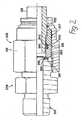
- Fig. 1shows an adaptor 145 according to the invention for converting a fitting body 110, particularly a standard 24° cone body, to a push-to-connect tube fitting assembly 108.
- the threaded fitting body 110has a threaded connecting portion 111 provided with an appropriate thread onto which a coupling nut 112 is screwed to form a chamber 113 between a bottom wall 135 of the coupling nut 112 and a conical end of the threaded fitting body 110.
- a seal part 115 and a support ring 117(which may also be referred to as a backup ring).
- the seal part 115includes a seal carrier 140 and a pair of annular seals, such as O-rings 141 and 142.
- the seal 141is retained in an annular groove 144 formed in the outer surface of a conical portion 145 of the carrier.
- the conical portion 145has the same cone angle as the interior surface 147 of the cone body 110, i.e., a 24° cone angle. Accordingly, the conical portion 145 will closely mate with the interior conical sealing surface 147 of the fitting body with the O-ring 141 sealing against the conical sealing surface 147.
- the other O-ring 142is received in an annular groove or notch 150 formed on the inner diameter surface of the seal carrier 140 for sealing to the outer diameter surface of the tube 119.
- the grooveis preferably at the outer axial end face 151 of the seal carrier, and the O-ring is axially trapped in the groove by the support ring 117 that has an inner axial end face 151 abutting the outer axial end face 151 of the seal carrier.
- the support ring 117has a bevelled surface radially inwardly of the inner axial end face 151 to form a triangular recess.
- the triangular recessis filled by a correspondingly sized anti-extrusion ring 154.
- the O-ring 141Under fluid pressure the O-ring 141 provides a seal at the interface with the conical sealing surface of the fitting body.
- the tube sealing O-ringwill push on the anti-extrusion ring forcing it to slide down the taper at the inner end of the support ring, closing any gap between the tube and the support ring. This prevents any extrusion of the O-ring between the support ring and the tube.
- the tube 119is provided with a bulge 120 that has a front expanding face or ramp 121 and a rear locking face 122. Both faces 121 and 122 may have conical shape with the slopes of the surfaces disposed opposite one another. As shown, the portion of the tube forward of the bulge may have an outer diameter smaller than the outer diameter of the tube behind the bulge, if desired.
- the support ring 117is correspondingly stepped at it inner surface, the axially outer portion corresponding in diameter to the outer diameter of the bulge and the axially inner portion corresponding in diameter to the outer diameter of tube forward of the bulge.
- the bulge 120cooperates with a resiliently expandable lock ring 123 disposed within the chamber 113 of the coupling nut 112.
- the lock ring 123is arranged between the support disk 117 and a bottom wall 135 of the coupling nut 112.
- the front expanding face 121Upon further insertion, the front expanding face 121 will cammingly cause the ring to expand radially in diameter until it can slide over the bulge. When the ring reaches the rear locking face 122, it will snap radially inwardly behind the bulge.
- the bottom wall 135 of the coupling nut 112is provided with a recess for receiving the lock ring 123.
- the recesshas a first recess step 124 forming a continuation of the chamber 113 and a second recess step 125 following the first step 124.
- the first recess step 124has such a dimension that allows the lock ring 123 to expand radially outwardly a distance sufficient to allow the lock ring to slide over the bulge when the tube is pushed through the lock ring.
- the second recess step 125is dimensioned such that it will closely surround the lock ring 123 when engaged behind the locking face 122 and thereby prevent the lock ring from expanding radially by an amount that would allow it to pass back over the bulge, i.e., the diameter of the step 125 is less than the outer diameter of the bulge.
- the lock ringwill grip behind the bulge and prevent the tube from being withdrawn when the lock ring is disposed in the recess step 125.
- Fig. 2shows another adaptor 245 according to the invention for converting a fitting body 210, particularly a Seal-Lok fitting body or other face seal fitting body that has O-ring 261 fitted in a groove 262 in the end face 263 of the fitting body, to a push-to-connect tube fitting assembly 208.
- the adaptor 245is the same as the adaptor 145 of Fig. 1 , except for a different configuration of the seal part 215.
- the seal part 215includes a seal carrier 240 of generally cylindrical shape that, like the seal carrier 140, is provided at its rear axial end with an annular groove or notch 250 formed on the inner diameter surface of the seal carrier for receiving the O-ring seal 242 that seals to the outer diameter surface of the tube 219.
- the seal carrierhowever, has a forward axial end face 265 that is perpendicular to the axis of the seal carrier and which is radially dimensioned to span substantially the full radial extent of the sealing face 262 of the fitting body 260.
- the axial end face 265serves as a sealing surface contacted by the O-ring 262 to seal the interface between the seal carrier 240 and the fitting body 260.
- Fig. 3shows yet another adaptor 345 according to the invention for converting a fitting body 360, particularly a Triple-Lok 37° flare tube fitting body or other flared tube fitting body that has a flared tube sealing surface 361 at the nose of the fitting body, to a push-to-connect tube fitting assembly 308.
- the adaptor 345is the same as the adaptor 145 of Fig. 1 , except for a different configuration of the seal part 315.
- the seal part 315includes a seal carrier 340 of generally cylindrical shape that, like the seal carrier 140, is provided at its rear axial end with an annular groove or notch 350 formed on the inner diameter surface of the seal carrier for receiving the O-ring seal 342 that seals to the outer diameter surface of the tube 319.
- the seal carrierhowever, has a forward axial end face 364 that is bevelled to match the bevel 361 at the nose of the fitting body 360.
- the bevelled end face 364has formed therein an annular groove 365 for receiving an annular seal 366 such as an O-ring as shown.
- the O-ring 366seals the interface between the seal carrier 340 and the fitting body 310.
- adaptors for converting standard port bodies to push-to-connect tube fitting assembliescan employ separate seal and support rings within a chamber of a coupling plug similar to what is described above in relation to a coupling nut.
- a seal ring 615includes a seal carrier 640 and an annular seal 642, and a support ring 617 formed separately of the coupling plug.
- the seal carrier 640also is sealed to the interior of the coupling plug by an annular seal 690, such as an O-ring retained in an annular groove formed in the outer diameter surface of the coupling plug as shown.
- the rear end of the seal ring and the forward end of the support ringmay be provided with matching tapers at 691 as shown such that when pressure is applied to the fitting assembly, the seal ring will be forced radially inwardly into tight gripping relationship when forced axially against the support ring by applied pressure. This will take up an clearance that might otherwise provide a gap for extrusion of the seal.
- the support ringmay also be provided with a taper for receiving an anti-extrusion ring 693 which functions as above described.
- Fig. 4also illustrates another form or retention device that may be used to hold the interior components of the adaptor within the coupling plug, or nut as the case may be.
- the axially inner end of the coupling plug/nutmay be swaged or otherwise bent radially inwardly to capture the axially innermost component to block its escape from the coupling nut when not assembled to a port or fitting body.
- the tubeis shown with a bulge or groove formed from or in the wall of the tube in the various exemplary embodiments described above and hereinafter claimed, the bulge can be provided by other devices, such as by a sleeve affixed to the tube.
- tubeor “tubes” encompasses not only tubes but other tubular members such as a hose or a tubular fitting, such as a short tubular piece to which a hose, tube or the like is or can be coupled.
Landscapes
- Engineering & Computer Science (AREA)
- General Engineering & Computer Science (AREA)
- Mechanical Engineering (AREA)
- Quick-Acting Or Multi-Walled Pipe Joints (AREA)
- Joints With Pressure Members (AREA)
- Communication Control (AREA)
Abstract
Description
- The invention relates to an adaptor converting a standard tube fitting/port to a push-to-connect tube fitting/port into which a tube can be pushed to effect a secure and sealed connection with the standard tube fitting/port by means of the adaptor.
- A connection arrangement for connection of a tube i. e. any tubular member to a tube fitting/port body showing the features of the preamble of claim 1 is known from
GB 2070709 A - It can be identified as an disadvantage of the known connection arrangement that the coupling nut as well as the fitting/port body each has to have an inner peripheral groove for receiving an annular seal manufacturing thereof is difficult and causes additional effort and cost.
- Within the
EP-A 1 561 988 only forming a state of art pursuant to art. 54 (3) and (4) EPC but showing the features of the preamble of claim 1 it is disclosed to arrange a separate ring in the inner of the coupling nut which ring carries on his one side an annular sealing gasket which possesses a root portion forming a seal between the tube and the axial end face of the fitting body and further a nose forming a seal between the tube and the conical surface of the tube receiving opening of the fitting body. - It is an object of the invention to improve the connection arrangement of the afore-mentioned kind with respect to the sealing of the tube to the coupling nut as well as to the fitting body and to simlify the assembly thereof.
- The invention is characterized by the features recited in the appended claims.
- In particular the invention provides an adaptor showing the features of the preamble of claim 1 which is characterized by that a separate seal carrier is arranged retaining the annular tube seal and that the sealing arrangement for sealing the tube to the standard tube fitting/port body consists of a body seal retained by the seal carrier in spaced apart relationship to the tube seal or of an axial end face sealing surface arranged on the seal carrier for sealing with an end face seal of a standard end face seal tube fitting/port body. Thus it is possible to manufacture the seal carrier as a separate part and to preassemble it as a part of the adaptor. Consequently the coupling nut, the seal carrier, the support ring and the lock ring preferably are preassembled to form the adaptor for converting the standard tube fitting/port body to a push-to-connect tube fitting. Suitable means may be employed to hold the seal carrier, support ring and lock ring in the coupling nut when not assembled to a fitting body. Such means may be press fitting the seal carrier or a retention ring into the coupling nut, which seal carrier or retention ring may be provided with a yieldable collar, such as a rubber or plastic collar, that provides a friction fit with the interior of the coupling nut (or plug).
- According to an embodiment of the invention the threaded end portion may include a straight thread.
- Further in accordance with the invention the support ring may be formed separately from the coupling nut and be axially inserted into and removed from the coupling nut/plug.
- According to another aspect of the invention the retention device may include a resiliently radially expandable lock ring and the support ring may form with a bottom wall of the coupling nut/plug a recess for accommodating the lock ring.
- The invention is also applicable to the connection of hose lines and/or connection of a hose line to a tube, the push-in tube being arranged as a tube piece with limited length whereby a hose line and/or hose fitting, may be attached to the tube piece.
- The invention also provides push-to-connect fitting/port assemblies comprising a standard tube fitting/port body and an adaptor according to the invention.
- The foregoing and other features of the invention are hereinafter described in detail in conjunction with the accompanying drawings which set forth exemplary embodiments illustrating a few of the various ways in which the principles of the invention may be employed.
- In the annexed drawings:
Fig. 1 is a cross-sectional view of an adaptor according to the invention, shown in combination with a standard tube fitting body and push-in tube;Fig. 2 is a cross-sectional view of another adaptor according to the invention, shown in combination with a standard tube fitting body and push-in tube;Fig. 3 is a cross-sectional view of another adaptor according to the invention, shown in combination with a standard tube fitting body and push-in tubeFig. 4 is a cross-sectional view of another adaptor according to the invention, shown in combination with a standard port body and push-in tube.- The invention will now be described in detail by way of various exemplary embodiments shown in the annexed figures.
Fig. 1 shows anadaptor 145 according to the invention for converting a fitting body 110, particularly a standard 24° cone body, to a push-to-connecttube fitting assembly 108. The threaded fitting body 110 has a threaded connecting portion 111 provided with an appropriate thread onto which acoupling nut 112 is screwed to form achamber 113 between abottom wall 135 of thecoupling nut 112 and a conical end of the threaded fitting body 110. Within thischamber 113 there is arranged aseal part 115 and a support ring 117 (which may also be referred to as a backup ring).- The
seal part 115 includes aseal carrier 140 and a pair of annular seals, such as O-rings 141 and 142. The seal 141 is retained in anannular groove 144 formed in the outer surface of aconical portion 145 of the carrier. Theconical portion 145 has the same cone angle as theinterior surface 147 of the cone body 110, i.e., a 24° cone angle. Accordingly, theconical portion 145 will closely mate with the interiorconical sealing surface 147 of the fitting body with the O-ring 141 sealing against theconical sealing surface 147. - The other O-ring 142 is received in an annular groove or
notch 150 formed on the inner diameter surface of theseal carrier 140 for sealing to the outer diameter surface of thetube 119. The groove is preferably at the outeraxial end face 151 of the seal carrier, and the O-ring is axially trapped in the groove by thesupport ring 117 that has an inneraxial end face 151 abutting the outeraxial end face 151 of the seal carrier. As is preferred, thesupport ring 117 has a bevelled surface radially inwardly of the inneraxial end face 151 to form a triangular recess. The triangular recess is filled by a correspondingly sized anti-extrusion ring 154. - Under fluid pressure the O-ring 141 provides a seal at the interface with the conical sealing surface of the fitting body. The tube sealing O-ring will push on the anti-extrusion ring forcing it to slide down the taper at the inner end of the support ring, closing any gap between the tube and the support ring. This prevents any extrusion of the O-ring between the support ring and the tube.
- The
tube 119 is provided with abulge 120 that has a front expanding face orramp 121 and arear locking face 122. Bothfaces support ring 117 is correspondingly stepped at it inner surface, the axially outer portion corresponding in diameter to the outer diameter of the bulge and the axially inner portion corresponding in diameter to the outer diameter of tube forward of the bulge. - The
bulge 120 cooperates with a resilientlyexpandable lock ring 123 disposed within thechamber 113 of thecoupling nut 112. Thelock ring 123 is arranged between thesupport disk 117 and abottom wall 135 of thecoupling nut 112. When the tube is inserted through a central opening in the bottom wall of the coupling nut and telescopically into the lock ring, the lock ring will freely pass over the end of the tube until it reaches thefront expanding face 121 of thebulge 120, since the ring in its normal relaxed condition has a diameter slightly greater than the outer diameter of the leading end of the tube but smaller than the outer diameter of thebulge 120. Upon further insertion, thefront expanding face 121 will cammingly cause the ring to expand radially in diameter until it can slide over the bulge. When the ring reaches therear locking face 122, it will snap radially inwardly behind the bulge. - The
bottom wall 135 of thecoupling nut 112 is provided with a recess for receiving thelock ring 123. The recess has afirst recess step 124 forming a continuation of thechamber 113 and a second recess step 125 following thefirst step 124. Thefirst recess step 124 has such a dimension that allows thelock ring 123 to expand radially outwardly a distance sufficient to allow the lock ring to slide over the bulge when the tube is pushed through the lock ring. The second recess step 125 is dimensioned such that it will closely surround thelock ring 123 when engaged behind thelocking face 122 and thereby prevent the lock ring from expanding radially by an amount that would allow it to pass back over the bulge, i.e., the diameter of the step 125 is less than the outer diameter of the bulge. Thus, the lock ring will grip behind the bulge and prevent the tube from being withdrawn when the lock ring is disposed in the recess step 125. Fig. 2 shows anotheradaptor 245 according to the invention for converting afitting body 210, particularly a Seal-Lok fitting body or other face seal fitting body that has O-ring 261 fitted in agroove 262 in theend face 263 of the fitting body, to a push-to-connecttube fitting assembly 208. Theadaptor 245 is the same as theadaptor 145 ofFig. 1 , except for a different configuration of theseal part 215. Theseal part 215 includes aseal carrier 240 of generally cylindrical shape that, like theseal carrier 140, is provided at its rear axial end with an annular groove ornotch 250 formed on the inner diameter surface of the seal carrier for receiving the O-ring seal 242 that seals to the outer diameter surface of thetube 219. The seal carrier, however, has a forwardaxial end face 265 that is perpendicular to the axis of the seal carrier and which is radially dimensioned to span substantially the full radial extent of the sealingface 262 of the fitting body 260. Theaxial end face 265 serves as a sealing surface contacted by the O-ring 262 to seal the interface between theseal carrier 240 and the fitting body 260.Fig. 3 shows yet anotheradaptor 345 according to the invention for converting a fitting body 360, particularly a Triple-Lok 37° flare tube fitting body or other flared tube fitting body that has a flaredtube sealing surface 361 at the nose of the fitting body, to a push-to-connect tubefitting assembly 308. Theadaptor 345 is the same as theadaptor 145 ofFig. 1 , except for a different configuration of theseal part 315. Theseal part 315 includes aseal carrier 340 of generally cylindrical shape that, like theseal carrier 140, is provided at its rear axial end with an annular groove or notch 350 formed on the inner diameter surface of the seal carrier for receiving the O-ring seal 342 that seals to the outer diameter surface of thetube 319. The seal carrier, however, has a forwardaxial end face 364 that is bevelled to match thebevel 361 at the nose of the fitting body 360. Thebevelled end face 364 has formed therein anannular groove 365 for receiving anannular seal 366 such as an O-ring as shown. The O-ring 366 seals the interface between theseal carrier 340 and thefitting body 310.- In addition, adaptors for converting standard port bodies to push-to-connect tube fitting assemblies can employ separate seal and support rings within a chamber of a coupling plug similar to what is described above in relation to a coupling nut. One example of this is shown in
Fig. 4 wherein aseal ring 615 includes aseal carrier 640 and anannular seal 642, and asupport ring 617 formed separately of the coupling plug. Theseal carrier 640 also is sealed to the interior of the coupling plug by anannular seal 690, such as an O-ring retained in an annular groove formed in the outer diameter surface of the coupling plug as shown. The rear end of the seal ring and the forward end of the support ring may be provided with matching tapers at 691 as shown such that when pressure is applied to the fitting assembly, the seal ring will be forced radially inwardly into tight gripping relationship when forced axially against the support ring by applied pressure. This will take up an clearance that might otherwise provide a gap for extrusion of the seal. The support ring may also be provided with a taper for receiving ananti-extrusion ring 693 which functions as above described. Fig. 4 also illustrates another form or retention device that may be used to hold the interior components of the adaptor within the coupling plug, or nut as the case may be. As shown, the axially inner end of the coupling plug/nut may be swaged or otherwise bent radially inwardly to capture the axially innermost component to block its escape from the coupling nut when not assembled to a port or fitting body.- Although the tube is shown with a bulge or groove formed from or in the wall of the tube in the various exemplary embodiments described above and hereinafter claimed, the bulge can be provided by other devices, such as by a sleeve affixed to the tube.
- Also, the reference herein to "tube" or "tubes" encompasses not only tubes but other tubular members such as a hose or a tubular fitting, such as a short tubular piece to which a hose, tube or the like is or can be coupled.
Claims (4)
- An adaptor (145, 245, 345, 645) for converting to a push-to-connect tube fitting/port a standard tube fitting/port body (110, 210, 310, 610) having a threaded portion (111) for threaded attachment of a nut/plug and a seal or sealing surface separate from the threaded portion of the standard tube fitting/port body, comprising:- a coupling nut/plug (112, 212, 312, 612) having an axially inner threaded end portion for threaded attachment to the threaded portion (111) of the fitting/port body;- an annular tube seal (142, 242, 342, 642) contained within the coupling nut/plug for sealing to an outer diameter surface of a tube (119) having a locking surface (122) spaced from the end of the tube;- a separate sealing arrangement for sealing the tube to the standard tube fitting/port body;- a radially expandable and contractible retention device (123, 222, 322, 622) retained in the coupling nut/plug, which coupling nut/plug has at an axially outer end thereof a central opening through which the tube can be inserted into the coupling nut/plug, whereby the locking surface (122) can be engaged by the retention device to prevent axial withdrawal of the tube from the coupling nut/plug once inserted;- a support ring (117, 217, 317, 617) separate from or integral with the coupling nut/plug and axially interposed between the retention device and the tube sealcharacterized in that a separate seal carrier (140, 240, 340, 640) is arranged retaining the annular tube seal (142, 242, 342, 642) and that the separate sealing arrangement for sealing the tube to the standard tube fitting/port body consists of a body seal (141, 366, 690) retained by the seal carrier (140, 340, 640) in spaced apart relationship to the tube seal or of an axial end face seal surface (265) arranged on the seal carrier (240) for sealing with an end face seal (261) of a standard end face seal tube fitting/port body (210).
- An adaptor recording to claim 1,characterized in that the threaded end portion includes a straight thread.
- An adaptor according to claim 1 or 2,characterized in that the support ring (117, 217, 317, 617) is formed separately from the coupling nut (112, 212, 312, 612), and can be axially inserted into and removed from the coupling nut/plug.
- An adaptor according to claim 3, wherein the retention device (123, 222, 322, 622) includes a resiliently radially expandable lock ring (123) and the support ring (117, 217, 317, 617) forms with a bottom wall (135) of the coupling nut/plug (100, 112, 212, 312, 612) a recess for accommodating the lock ring.
Applications Claiming Priority (2)
| Application Number | Priority Date | Filing Date | Title |
|---|---|---|---|
| DE102004035354ADE102004035354B3 (en) | 2004-07-21 | 2004-07-21 | Plug connection for metal pipes |
| PCT/US2005/026271WO2006012598A1 (en) | 2004-07-21 | 2005-07-21 | Adaptor and method for converting standard tube fitting/port to push-to-connect tube fitting/port |
Publications (2)
| Publication Number | Publication Date |
|---|---|
| EP1771678A1 EP1771678A1 (en) | 2007-04-11 |
| EP1771678B1true EP1771678B1 (en) | 2010-12-08 |
Family
ID=35058590
Family Applications (1)
| Application Number | Title | Priority Date | Filing Date |
|---|---|---|---|
| EP05775901AExpired - LifetimeEP1771678B1 (en) | 2004-07-21 | 2005-07-21 | Adaptor and method for converting standard tube fitting/port to push-to-connect tube fitting/port |
Country Status (8)
| Country | Link |
|---|---|
| US (1) | US7914050B2 (en) |
| EP (1) | EP1771678B1 (en) |
| KR (1) | KR101343900B1 (en) |
| AT (1) | ATE491110T1 (en) |
| CA (1) | CA2578446C (en) |
| DE (1) | DE602005025223D1 (en) |
| MX (1) | MX2007002145A (en) |
| WO (1) | WO2006012598A1 (en) |
Families Citing this family (40)
| Publication number | Priority date | Publication date | Assignee | Title |
|---|---|---|---|---|
| US8240719B2 (en)* | 2004-07-21 | 2012-08-14 | Parker-Hannifin Corporation | Adaptor and method for converting standard tube fitting/port to push-to-connect tube fitting/port |
| WO2007084183A1 (en)* | 2006-01-20 | 2007-07-26 | Parker-Hannifin Corporation | Adaptor and method for converting standard tube fitting/port to push-to-connect tube fitting/port |
| US7537244B2 (en) | 2006-02-23 | 2009-05-26 | Parker Hannifin Corporation | Fluid fitting assembly |
| US8480134B2 (en) | 2007-05-25 | 2013-07-09 | Quick Fitting, Inc. | Piping joint assembly system and method with sealing ring stabilizer |
| US8205915B1 (en) | 2007-05-25 | 2012-06-26 | Quick Fitting, Inc. | Piping joint assembly system and method |
| EP2158425B1 (en)* | 2007-06-18 | 2011-01-05 | Weidmann LTD. | Connecting arrangement for a pipe union |
| WO2008154951A1 (en)* | 2007-06-18 | 2008-12-24 | Weidmann Ltd. | Connecting arrangement for a pipe union |
| US20090167049A1 (en)* | 2007-12-26 | 2009-07-02 | Lariviere Ian P | Vehicle cover |
| WO2012018576A1 (en)* | 2010-07-26 | 2012-02-09 | Swagelok Company | Single axis push to connect conduit fitting |
| EP2627938B1 (en) | 2010-10-15 | 2018-09-05 | Swagelok Company | Push to connect conduit fitting with ferrule |
| US8398122B2 (en) | 2010-12-30 | 2013-03-19 | Quick Fitting, Inc. | Push connect joint assembly, system and method |
| KR101498237B1 (en)* | 2013-05-28 | 2015-03-06 | 주식회사 에어컨이엔지 | Apparatus of fixing pressure gauge for air conditioner |
| DE202013103050U1 (en)* | 2013-07-09 | 2013-09-10 | Kreyenborg Verwaltungen Und Beteiligungen Gmbh & Co. Kg | Length-adjustable adapter device for connecting a plant part of a plastics processing plant with a pipeline |
| JP6651453B2 (en) | 2013-10-24 | 2020-02-19 | スウエイジロク・カンパニー | Single acting push type connection pipe joint |
| US10359141B2 (en)* | 2014-01-14 | 2019-07-23 | The Boeing Company | Tube fitting |
| US10060563B2 (en) | 2014-01-14 | 2018-08-28 | The Boeing Company | Tube fitting |
| US11262013B2 (en) | 2014-01-14 | 2022-03-01 | The Boeing Company | Tube fitting |
| DE102014100758B4 (en)* | 2014-01-23 | 2015-07-30 | Parker Hannifin Manufacturing Germany GmbH & Co. KG | Play-free plug connection for pipe and hose lines |
| US9939095B2 (en) | 2014-01-29 | 2018-04-10 | The Boeing Company | Tube fitting |
| BR112017006628B1 (en) | 2014-09-30 | 2021-09-08 | Flexsteel Pipeline Technologies, Inc | PIPE CONNECTOR AND METHOD OF ASSEMBLY OF A PIPE CONNECTOR |
| EP3597979B1 (en) | 2015-04-23 | 2021-09-29 | Swagelok Company | Single action push to connect conduit fitting with colleting |
| US10458582B2 (en) | 2015-04-23 | 2019-10-29 | Swagelok Company | Single action push to connect conduit fitting with colleting |
| US9879810B2 (en) | 2015-09-18 | 2018-01-30 | Quick Fitting, Inc. | Push-to-connect joint assembly with protective shield device and method |
| US9562637B1 (en) | 2015-09-22 | 2017-02-07 | Quick Fitting, Inc. | Locking pipe joint assembly, device and method |
| US9857006B2 (en) | 2016-03-31 | 2018-01-02 | Quick Fitting, Inc. | Retaining ring for pipe joint devices |
| US9671049B1 (en) | 2016-07-27 | 2017-06-06 | Quick Fitting, Inc. | Hybrid push-to-connect fitting device and assembly |
| CN106838502A (en)* | 2017-03-23 | 2017-06-13 | 四川柯世达汽车制动系统集团有限公司 | Collar joint flexible sealing structure |
| US11519529B2 (en)* | 2017-05-31 | 2022-12-06 | Hanon Systems | Metal sealing threaded (tube-o) fitting |
| US10400929B2 (en) | 2017-09-27 | 2019-09-03 | Quick Fitting, Inc. | Fitting device, arrangement and method |
| KR20200085169A (en) | 2019-01-04 | 2020-07-14 | 주식회사 레인테크 | Inspecting apparatus for pipe portion and diagnostic apparatus having the same |
| CN113518879B (en) | 2019-04-01 | 2023-12-15 | 斯瓦戈洛克公司 | Push-to-connect catheter adapter assembly and apparatus |
| CN110566732A (en)* | 2019-09-23 | 2019-12-13 | 黄子颢 | Pipeline connecting piece |
| US11662045B2 (en) | 2019-10-30 | 2023-05-30 | Parker-Hannifin Corporation | Fluid connection system with a push-to-connect face seal configuration |
| CN114867961B (en)* | 2019-12-19 | 2024-07-09 | 欧梯克纽约股份有限公司 | Fluid connector including built-in retention clip |
| US10969047B1 (en) | 2020-01-29 | 2021-04-06 | Quick Fitting Holding Company, Llc | Electrical conduit fitting and assembly |
| US11035510B1 (en) | 2020-01-31 | 2021-06-15 | Quick Fitting Holding Company, Llc | Electrical conduit fitting and assembly |
| US11460137B2 (en) | 2020-03-12 | 2022-10-04 | Parker-Hannifin Corporation | Fluid connection systems |
| CN111828744B (en)* | 2020-07-16 | 2025-01-21 | 格力电器(武汉)有限公司 | Test system for connectors matching stop valves and air conditioners |
| US11105452B1 (en) | 2021-02-25 | 2021-08-31 | Quick Fitting Holding Company, Llc | Push-to-connect joint assembly and device |
| KR102749644B1 (en) | 2023-09-08 | 2025-01-03 | 이승아 | Structure for connecting pipe to hydraulic port |
Family Cites Families (128)
| Publication number | Priority date | Publication date | Assignee | Title |
|---|---|---|---|---|
| US2125677A (en)* | 1937-08-05 | 1938-08-02 | Kuchenmeister George | Beverage cooler and fitting |
| US2253018A (en)* | 1939-07-17 | 1941-08-19 | Cowles And Rudolph W Lotz | Swivel joint for conduits |
| US2805089A (en)* | 1954-12-30 | 1957-09-03 | Hansen Mfg Co | Pipe coupling with wedged spring ring detent means |
| US2914344A (en)* | 1955-04-06 | 1959-11-24 | Union Carbide Corp | Quick detachable safety connection between blowpipe body and stem |
| US2898130A (en)* | 1958-01-20 | 1959-08-04 | Hansen Mfg Co | Safety seal |
| US3120968A (en)* | 1960-04-21 | 1964-02-11 | John H Calvin | Quick disconnect coupling with ring detent |
| US3177018A (en)* | 1963-01-02 | 1965-04-06 | Aeroquip Corp | Snap ring coupling |
| US3317220A (en)* | 1963-04-15 | 1967-05-02 | Earl F Bruning | Releasable fluid coupling |
| US3398977A (en)* | 1965-02-13 | 1968-08-27 | Yoneda Rikizo | Pipe coupling |
| US3361453A (en)* | 1965-07-02 | 1968-01-02 | Brown Oil Tools | Quick coupling device |
| US3447819A (en)* | 1966-12-30 | 1969-06-03 | Adolph W Borsum | Push-pull connector having combined seal and locking ring |
| US3646964A (en)* | 1967-02-28 | 1972-03-07 | Parker Hannifin Corp | Coupling device for permitting coupling under trapped pressure |
| US3532101A (en)* | 1967-09-25 | 1970-10-06 | Srm Co | Low pressure gas coupling |
| US3540760A (en)* | 1969-03-24 | 1970-11-17 | Weatherhead Co | Quick connect coupling |
| US3592231A (en)* | 1969-10-17 | 1971-07-13 | Parker Hannifin Corp | Quick connect couplings with selective connection means |
| US3637239A (en)* | 1969-10-30 | 1972-01-25 | Johns Manville | Thrust-resistant pipe joint |
| US3666300A (en)* | 1970-03-26 | 1972-05-30 | Parker Hannifin Corp | Quick disconnect coupling |
| US3758137A (en)* | 1971-11-03 | 1973-09-11 | Parker Hannifin Corp | Quick disconnect coupling |
| US3788348A (en)* | 1971-11-03 | 1974-01-29 | Parker Hannifin Corp | Valve guide |
| US3831984A (en)* | 1971-11-08 | 1974-08-27 | Parker Hannifin Corp | Quick disconnect coupling |
| US3871691A (en)* | 1972-08-14 | 1975-03-18 | Tatsuya Takagi | Pipe joint |
| US3773360A (en) | 1972-09-01 | 1973-11-20 | W Timbers | Quick disconnect coupling |
| US3826523A (en)* | 1972-11-22 | 1974-07-30 | Parker Hannifin Corp | Quick connect tube coupling joint |
| US3847421A (en) | 1972-11-24 | 1974-11-12 | Parker Hannifin Corp | Quick connect tube coupling joint |
| US3922011A (en) | 1973-12-11 | 1975-11-25 | Tom Walters | Hose coupling |
| US3887222A (en)* | 1974-07-25 | 1975-06-03 | Hansen Mfg | Coupling with push-pull release |
| DE2650370C2 (en)* | 1975-11-12 | 1986-12-04 | Kjell Ronny Zug Ekman | Lockable line coupling |
| US4055359A (en)* | 1975-11-17 | 1977-10-25 | Ford Motor Company | Quick-connect tubular couplings |
| US4111464A (en)* | 1976-01-19 | 1978-09-05 | Sekisui Kagaku Kogyo Kabushiki Kaisha | Pipe joint locking ring and groove arrangement |
| US4077433A (en)* | 1976-05-17 | 1978-03-07 | The Bruning Company | Quick coupling device |
| US4105226A (en)* | 1976-06-01 | 1978-08-08 | Celanese Corporation | Snap-in fittings and coupling ring therefor |
| US4087120A (en)* | 1976-06-16 | 1978-05-02 | Michigan Pipe Fittings Company, Div. Of Michigan Hanger Co. Inc. | Pipe coupling with a wedging contractile ring |
| US4063760A (en)* | 1976-10-27 | 1977-12-20 | The Weatherhead Company | Quick connect coupling |
| US4186946A (en)* | 1977-05-13 | 1980-02-05 | Eaton Corporation | Rotatable hose or tube coupling |
| US4191408A (en)* | 1977-05-27 | 1980-03-04 | The Weatherhead Company | Automotive quick connect tube coupling |
| AU526361B2 (en)* | 1978-03-18 | 1983-01-06 | Girling Limited | Hydraulic pressure converters |
| US4193616A (en)* | 1978-05-18 | 1980-03-18 | Dana Corporation | Quick connect fitting |
| US4198080A (en)* | 1978-05-19 | 1980-04-15 | Baxter Travenol Laboratories, Inc. | Telescoping-type connector |
| FR2427506A1 (en) | 1978-06-02 | 1979-12-28 | Citroen Sa | ELASTIC RING FOR IMMOBILIZATION OF RIBBED OR TOOTHED PARTS |
| DE2824943C2 (en)* | 1978-06-07 | 1986-07-31 | Armaturenfabrik Hermann Voss GmbH + Co, 5272 Wipperfürth | Connection device for brake lines |
| US4216982A (en)* | 1978-12-26 | 1980-08-12 | Beatrice Foods Co. | Speed slip-on hose coupler |
| US4240466A (en) | 1979-01-15 | 1980-12-23 | Parker-Hannifin Corporation | Push-pull coupling |
| US4222411A (en)* | 1979-01-19 | 1980-09-16 | Parker-Hannifin Corporation | Lever actuated fluid coupling |
| US4294473A (en)* | 1979-03-16 | 1981-10-13 | Ekman Engineering Ag | Device at mutually lockable first and second parts |
| US4240654A (en) | 1979-09-28 | 1980-12-23 | International Harvester Company | Hose end coupling unit |
| DE3007509C2 (en) | 1980-02-28 | 1982-12-02 | Wavin B.V., 8031 Zwolle | Pipe coupling |
| US4401326A (en)* | 1981-12-16 | 1983-08-30 | Ford Motor Company | Quick-connect tubular coupling |
| GB2123105B (en)* | 1982-06-07 | 1986-05-08 | Btr Plc | Pipe coupling |
| US4485845A (en) | 1982-09-20 | 1984-12-04 | Imperial Clevite Inc. | Quick disconnect coupling |
| US4543994A (en)* | 1982-12-20 | 1985-10-01 | Parker-Hannifin Corporation | Rigid mount coupler |
| JPS59150087U (en)* | 1983-03-26 | 1984-10-06 | 千代田通商株式会社 | hose fitting |
| US4543993A (en)* | 1983-04-04 | 1985-10-01 | Calvin John H | Positive locking connector |
| US4662656A (en)* | 1983-09-09 | 1987-05-05 | Foster-Miller, Inc. | Pipeline coupling |
| DE3419999C2 (en)* | 1984-05-29 | 1987-02-12 | Karl 7298 Loßburg Hehl | Pipe fitting with contact seal |
| US4733890A (en)* | 1984-07-09 | 1988-03-29 | Stratoflex, Inc. | Formed fluid coupling apparatus |
| US4565392A (en)* | 1984-07-09 | 1986-01-21 | Stratoflex, Inc. | Quick connect coupling |
| US4848402A (en)* | 1985-04-06 | 1989-07-18 | Zahnradfabrik Friedrichshafen, Ag. | Rotary slide valve for hydraulic auxiliary power steerings |
| FR2582378B1 (en)* | 1985-05-21 | 1987-07-17 | Parker Hannifin Rak Sa | IMPROVEMENT IN VALVE COUPLERS TO FACILITATE THE RETURN OF LOCKING BALLS IN THE LOCKING POSITION |
| FR2582379B1 (en) | 1985-05-21 | 1987-12-31 | Parker Hannifin Rak Sa | IMPROVEMENT IN VALVE COUPLERS FOR ALLOWING A CONNECTION DESPITE HIGH RESIDUAL PRESSURE IN THE CIRCUIT OF USE |
| US4583711A (en)* | 1985-06-28 | 1986-04-22 | Parker-Hannifin Corporation | Rigid mount coupler with flow check stop |
| US4645245A (en)* | 1985-10-07 | 1987-02-24 | General Motors Corporation | Quick connect tube coupling |
| US4660803A (en)* | 1986-02-26 | 1987-04-28 | Suncast Corporation | Quick coupling connector for connecting flexible liquid conduits |
| US4647082A (en)* | 1986-03-17 | 1987-03-03 | Aeroquip Corporation | Releasable push-in connect fitting |
| FR2610385B1 (en)* | 1987-02-03 | 1989-07-13 | Peugeot | QUICK ASSEMBLY FITTING |
| JPH0317112Y2 (en)* | 1987-05-29 | 1991-04-11 | ||
| US4750765A (en)* | 1987-07-27 | 1988-06-14 | Stratoflex, Inc. | Quick-connect coupling |
| US5042848A (en)* | 1987-11-16 | 1991-08-27 | Fujipura Seiko Co. | Swivelable connector for tubular conduits |
| US4848802A (en)* | 1988-02-08 | 1989-07-18 | Fluoroware, Inc. | Tubing connector assembly |
| GB2217927B (en)* | 1988-03-12 | 1992-04-01 | Electronic Components Ltd | Bayonet coupling connector |
| US4906031A (en)* | 1988-07-21 | 1990-03-06 | Stratoflex, Inc. | Quick connect coupling with garter spring |
| US4872710A (en) | 1988-10-07 | 1989-10-10 | Stratoflex, Inc. | Releasable quick connect fitting |
| US5005877A (en)* | 1988-12-16 | 1991-04-09 | Parker Hannifin Corporation | Quick connect/disconnect fluid coupling |
| US5060689A (en)* | 1989-08-24 | 1991-10-29 | Ced's, Inc. | Universal check valve assembly |
| DE3931126A1 (en)* | 1989-09-18 | 1991-03-28 | Yokohama Aeroquip | PIPE COUPLING |
| DE3933591C1 (en) | 1989-10-07 | 1991-02-07 | Rasmussen Gmbh, 6457 Maintal, De | |
| GB2239503A (en) | 1989-12-29 | 1991-07-03 | Allen Ind Limited | Hose connectors |
| JP2538385B2 (en)* | 1990-03-30 | 1996-09-25 | 東海ゴム工業株式会社 | connector |
| DE4034803A1 (en) | 1990-11-02 | 1992-05-07 | Parker Ermeto Gmbh | CONNECTION SYSTEM |
| DE4038539C1 (en)* | 1990-12-03 | 1992-04-30 | Parker-Ermeto Gmbh, 4800 Bielefeld, De | |
| US5240023A (en)* | 1991-04-08 | 1993-08-31 | Gad Shelef | Safety hose coupler |
| DE69112031T2 (en) | 1991-04-09 | 1996-01-11 | Cooper Cameron Corp | Retaining ring. |
| JPH0753032Y2 (en)* | 1991-06-11 | 1995-12-06 | 日東工器株式会社 | Pipe fitting |
| EP0536434B1 (en)* | 1991-10-08 | 1994-09-28 | RECTUS-APPARATEBAU Walter Klein GmbH | Self-vented quick coupling for pressurized gas pipes, especially for compressed air pipes |
| US5280967A (en)* | 1992-03-27 | 1994-01-25 | Donald Travis | Device for indicating the proper installation of fittings |
| US5301408A (en)* | 1992-03-31 | 1994-04-12 | R & B, Inc. | Garter spring coupling release tool |
| US5226682A (en)* | 1992-07-21 | 1993-07-13 | Aeroquip Corporation | Coupling assembly |
| EP0610538A1 (en) | 1993-02-12 | 1994-08-17 | Anton Hummel Verwaltungs GmbH | Quick connection for pipes, hoses and the like |
| US5419594A (en)* | 1993-12-03 | 1995-05-30 | W. A. Thomas Co. | Quick-connect conduit coupling |
| DE9401501U1 (en) | 1994-01-29 | 1994-03-10 | Armaturenfabrik Hermann Voss GmbH + Co, 51688 Wipperfürth | Plug-in coupling for pressure line systems |
| US5385331A (en)* | 1994-03-15 | 1995-01-31 | Aeroquip Corporation | Valve assembly |
| US5472242A (en) | 1994-06-24 | 1995-12-05 | Petersen; Horst U. | End-fitting for pipe connection having proper insertion indicator |
| US5553895A (en)* | 1995-05-03 | 1996-09-10 | Aeroquip Corporation | Coupling assembly |
| US5509695A (en)* | 1995-06-01 | 1996-04-23 | Pilot Industries, Inc. | Precocked quick connect fluid coupling having a v-shaped holding ring |
| DE19520099C3 (en) | 1995-06-01 | 2002-05-29 | Walterscheid Gmbh Jean | Pipe connection and process for its manufacture |
| US5671955A (en)* | 1995-06-09 | 1997-09-30 | American Fence Corporation | Threadless pipe coupler for sprinkler pipe |
| US5611923A (en)* | 1995-07-12 | 1997-03-18 | Vickers, Inc. | Filter assembly having quick connect/disconnect sealing valve means |
| US5876071A (en)* | 1995-07-28 | 1999-03-02 | Aldridge; James H. | Quick connect/disconnect connector and method for use |
| GB2306593A (en)* | 1995-08-04 | 1997-05-07 | Smiths Industries Plc | Releasable Fluid coupling |
| US5570910A (en) | 1995-08-18 | 1996-11-05 | Aeroquip Corporation | Coupling assembly |
| US5709415A (en)* | 1995-09-11 | 1998-01-20 | Xyzyx International Corporation | Quick connect disconnect coupling |
| US5685575A (en) | 1995-11-03 | 1997-11-11 | Aeroquip Corporation | Power steering coupling assembly |
| US5709243A (en)* | 1995-11-20 | 1998-01-20 | Aeroquip Corporation | Low spill female coupling |
| US6036237A (en)* | 1996-05-09 | 2000-03-14 | Parker-Hannifin Corporation | Coupling for corrugated tubing |
| WO1997042442A1 (en)* | 1996-05-09 | 1997-11-13 | Parker-Hannifin Corporation | Coupling for corrugated tubing |
| DE19624524C2 (en)* | 1996-06-20 | 1998-07-02 | Raymond A & Cie | Detachable connector with assembly display |
| US5711553A (en)* | 1996-09-04 | 1998-01-27 | Stmc-Llc | Quick connect fluid coupling |
| US5931509A (en)* | 1996-11-19 | 1999-08-03 | Proprietary Technology, Inc. | Connection verification and secondary latch device |
| DE29803195U1 (en)* | 1998-02-24 | 1999-06-24 | Johannes Schäfer vorm. Stettiner Schraubenwerke GmbH & Co KG, 35410 Hungen | Combination of a plug connection for pipes and a release tool |
| US5893391A (en)* | 1997-07-11 | 1999-04-13 | Aeroquip Corporation | Coupling latch |
| US5975159A (en) | 1997-09-09 | 1999-11-02 | Fogg Filler Company | Container filler apparatus external disconnect valve |
| EP0905431A3 (en)* | 1997-09-30 | 1999-09-15 | Aeroquip-Vickers International GmbH | Coupling device |
| US5918913A (en)* | 1997-10-30 | 1999-07-06 | Dana Corporation | Quick-connect coupling for articulating hose lines |
| US6142858A (en)* | 1997-11-10 | 2000-11-07 | 3M Innovative Properties Company | Backup pad for abrasive articles |
| US6095910A (en)* | 1997-11-10 | 2000-08-01 | 3M Innovative Properties Company | Surface treatment article having a quick release fastener |
| DE29805720U1 (en) | 1998-03-28 | 1999-08-05 | Armaturenfabrik Hermann Voss GmbH + Co, 51688 Wipperfürth | Plug-in coupling for pressure medium systems |
| US6089250A (en)* | 1998-06-19 | 2000-07-18 | Johnson; Oriz Wickline | Inflater gauge having vandal-resistant accessory attachment means |
| US6056010A (en)* | 1998-07-23 | 2000-05-02 | Aeroquip Corporation | Anti-check low spill fluid coupling |
| EP1137893B1 (en)* | 1998-12-11 | 2002-08-14 | Eaton Fluid Power GmbH | Coupling system with blocking device |
| DE19918174A1 (en)* | 1999-04-21 | 2000-10-26 | Vickers Aeroquip Int Gmbh | Quick coupling |
| US6237631B1 (en)* | 1999-08-19 | 2001-05-29 | Parker-Hannifin Corporation | Low spill quick disconnect coupling |
| DE19958475A1 (en)* | 1999-11-30 | 2001-06-13 | Parker Hannifin Gmbh | Pipe connection and process for its manufacture |
| US6450545B1 (en)* | 2001-02-21 | 2002-09-17 | Parker Hennifin Corporation | Fluid coupling plug |
| DE10214997B4 (en) | 2002-04-05 | 2005-04-07 | Voswinkel Kg | Hydraulic connector device |
| DE20205833U1 (en)* | 2002-04-15 | 2002-07-04 | Voss Automotive GmbH, 51688 Wipperfürth | Plug-in coupling for fluidic systems |
| SE527219C2 (en) | 2003-11-18 | 2006-01-24 | Specma Hydraulic Ab | Coupling arrangement is for hydraulic connection in form of tube or rod and has male part provided with conical part and connected external ring-shaped locking track |
| FR2865789B1 (en) | 2004-02-04 | 2006-03-10 | Legris Sa | INSTANT COUPLING COUPLING |
| US7600790B2 (en)* | 2004-10-20 | 2009-10-13 | Eaton Corporation | Coupling assembly with connection indicator |
| CA2585076C (en)* | 2004-10-29 | 2009-12-29 | The Gates Corporation | Quick connect coupling |
- 2005
- 2005-07-21CACA2578446Apatent/CA2578446C/ennot_activeExpired - Lifetime
- 2005-07-21ATAT05775901Tpatent/ATE491110T1/ennot_activeIP Right Cessation
- 2005-07-21EPEP05775901Apatent/EP1771678B1/ennot_activeExpired - Lifetime
- 2005-07-21MXMX2007002145Apatent/MX2007002145A/enunknown
- 2005-07-21WOPCT/US2005/026271patent/WO2006012598A1/enactiveApplication Filing
- 2005-07-21DEDE602005025223Tpatent/DE602005025223D1/ennot_activeExpired - Lifetime
- 2005-07-21USUS11/572,472patent/US7914050B2/enactiveActive
- 2007
- 2007-02-21KRKR1020077004109Apatent/KR101343900B1/ennot_activeExpired - Lifetime
Also Published As
| Publication number | Publication date |
|---|---|
| ATE491110T1 (en) | 2010-12-15 |
| US7914050B2 (en) | 2011-03-29 |
| WO2006012598A1 (en) | 2006-02-02 |
| KR20070052282A (en) | 2007-05-21 |
| DE602005025223D1 (en) | 2011-01-20 |
| CA2578446C (en) | 2013-02-12 |
| KR101343900B1 (en) | 2013-12-20 |
| MX2007002145A (en) | 2007-09-14 |
| CA2578446A1 (en) | 2006-02-02 |
| US20080136178A1 (en) | 2008-06-12 |
| EP1771678A1 (en) | 2007-04-11 |
Similar Documents
| Publication | Publication Date | Title |
|---|---|---|
| EP1771678B1 (en) | Adaptor and method for converting standard tube fitting/port to push-to-connect tube fitting/port | |
| US8240719B2 (en) | Adaptor and method for converting standard tube fitting/port to push-to-connect tube fitting/port | |
| US4193616A (en) | Quick connect fitting | |
| EP1979663B1 (en) | Adaptor and method for converting standard tube fitting/port to push-to-connect tube fitting/port | |
| US4993755A (en) | Quick connect fitting | |
| JP2758949B2 (en) | Fitting sleeve | |
| CA1073497A (en) | Quick connect coupling | |
| US5779284A (en) | Tube coupling bodies having resilient fingers spaced from the groove wall | |
| US7338094B2 (en) | Plug-in coupling for fluidic systems | |
| US5803512A (en) | Tube quick connect to female socket | |
| JPH08501863A (en) | Joint for engaging the outer peripheral surface of resin pipe | |
| US4621842A (en) | Releasable push-to-connect tube fitting | |
| US5511830A (en) | Quick connect tube couplings | |
| EP1099895B1 (en) | Connector | |
| US4220359A (en) | Push-to-connect air brake fitting | |
| US5112087A (en) | Pipe joint | |
| US4302036A (en) | Tube coupling | |
| US20010052699A1 (en) | Moulded plastics tubular couplings | |
| US7390033B2 (en) | Screw connection device for connecting the flared ends of two pipes | |
| EP1368590B1 (en) | Pipe coupling | |
| US3971577A (en) | Union device for flexible tubing | |
| EP0957305A2 (en) | A pneumatic connector | |
| JP2003166679A (en) | Plug-in connector | |
| KR102741513B1 (en) | Quick connect | |
| GB2278658A (en) | Compression fitting |
Legal Events
| Date | Code | Title | Description |
|---|---|---|---|
| PUAI | Public reference made under article 153(3) epc to a published international application that has entered the european phase | Free format text:ORIGINAL CODE: 0009012 | |
| 17P | Request for examination filed | Effective date:20070213 | |
| AK | Designated contracting states | Kind code of ref document:A1 Designated state(s):AT BE BG CH CY CZ DE DK EE ES FI FR GB GR HU IE IS IT LI LT LU LV MC NL PL PT RO SE SI SK TR | |
| AX | Request for extension of the european patent | Extension state:HR MK YU | |
| RAX | Requested extension states of the european patent have changed | Extension state:YU Payment date:20070213 Extension state:HR Payment date:20070213 Extension state:AL Payment date:20070213 Extension state:MK Payment date:20070213 Extension state:BA Payment date:20070213 | |
| 17Q | First examination report despatched | Effective date:20080508 | |
| GRAP | Despatch of communication of intention to grant a patent | Free format text:ORIGINAL CODE: EPIDOSNIGR1 | |
| GRAS | Grant fee paid | Free format text:ORIGINAL CODE: EPIDOSNIGR3 | |
| GRAA | (expected) grant | Free format text:ORIGINAL CODE: 0009210 | |
| AK | Designated contracting states | Kind code of ref document:B1 Designated state(s):AT BE BG CH CY CZ DE DK EE ES FI FR GB GR HU IE IS IT LI LT LU LV MC NL PL PT RO SE SI SK TR | |
| AX | Request for extension of the european patent | Extension state:AL BA HR MK YU | |
| REG | Reference to a national code | Ref country code:GB Ref legal event code:FG4D | |
| REG | Reference to a national code | Ref country code:CH Ref legal event code:EP | |
| REG | Reference to a national code | Ref country code:IE Ref legal event code:FG4D | |
| REF | Corresponds to: | Ref document number:602005025223 Country of ref document:DE Date of ref document:20110120 Kind code of ref document:P | |
| REG | Reference to a national code | Ref country code:NL Ref legal event code:VDEP Effective date:20101208 | |
| PG25 | Lapsed in a contracting state [announced via postgrant information from national office to epo] | Ref country code:LT Free format text:LAPSE BECAUSE OF FAILURE TO SUBMIT A TRANSLATION OF THE DESCRIPTION OR TO PAY THE FEE WITHIN THE PRESCRIBED TIME-LIMIT Effective date:20101208 | |
| LTIE | Lt: invalidation of european patent or patent extension | Effective date:20101208 | |
| PG25 | Lapsed in a contracting state [announced via postgrant information from national office to epo] | Ref country code:BG Free format text:LAPSE BECAUSE OF FAILURE TO SUBMIT A TRANSLATION OF THE DESCRIPTION OR TO PAY THE FEE WITHIN THE PRESCRIBED TIME-LIMIT Effective date:20110308 Ref country code:SE Free format text:LAPSE BECAUSE OF FAILURE TO SUBMIT A TRANSLATION OF THE DESCRIPTION OR TO PAY THE FEE WITHIN THE PRESCRIBED TIME-LIMIT Effective date:20101208 Ref country code:AT Free format text:LAPSE BECAUSE OF FAILURE TO SUBMIT A TRANSLATION OF THE DESCRIPTION OR TO PAY THE FEE WITHIN THE PRESCRIBED TIME-LIMIT Effective date:20101208 Ref country code:CY Free format text:LAPSE BECAUSE OF FAILURE TO SUBMIT A TRANSLATION OF THE DESCRIPTION OR TO PAY THE FEE WITHIN THE PRESCRIBED TIME-LIMIT Effective date:20101208 Ref country code:FI Free format text:LAPSE BECAUSE OF FAILURE TO SUBMIT A TRANSLATION OF THE DESCRIPTION OR TO PAY THE FEE WITHIN THE PRESCRIBED TIME-LIMIT Effective date:20101208 Ref country code:SI Free format text:LAPSE BECAUSE OF FAILURE TO SUBMIT A TRANSLATION OF THE DESCRIPTION OR TO PAY THE FEE WITHIN THE PRESCRIBED TIME-LIMIT Effective date:20101208 Ref country code:NL Free format text:LAPSE BECAUSE OF FAILURE TO SUBMIT A TRANSLATION OF THE DESCRIPTION OR TO PAY THE FEE WITHIN THE PRESCRIBED TIME-LIMIT Effective date:20101208 Ref country code:LV Free format text:LAPSE BECAUSE OF FAILURE TO SUBMIT A TRANSLATION OF THE DESCRIPTION OR TO PAY THE FEE WITHIN THE PRESCRIBED TIME-LIMIT Effective date:20101208 | |
| PG25 | Lapsed in a contracting state [announced via postgrant information from national office to epo] | Ref country code:GR Free format text:LAPSE BECAUSE OF FAILURE TO SUBMIT A TRANSLATION OF THE DESCRIPTION OR TO PAY THE FEE WITHIN THE PRESCRIBED TIME-LIMIT Effective date:20110309 Ref country code:EE Free format text:LAPSE BECAUSE OF FAILURE TO SUBMIT A TRANSLATION OF THE DESCRIPTION OR TO PAY THE FEE WITHIN THE PRESCRIBED TIME-LIMIT Effective date:20101208 Ref country code:CZ Free format text:LAPSE BECAUSE OF FAILURE TO SUBMIT A TRANSLATION OF THE DESCRIPTION OR TO PAY THE FEE WITHIN THE PRESCRIBED TIME-LIMIT Effective date:20101208 Ref country code:PT Free format text:LAPSE BECAUSE OF FAILURE TO SUBMIT A TRANSLATION OF THE DESCRIPTION OR TO PAY THE FEE WITHIN THE PRESCRIBED TIME-LIMIT Effective date:20110408 Ref country code:IS Free format text:LAPSE BECAUSE OF FAILURE TO SUBMIT A TRANSLATION OF THE DESCRIPTION OR TO PAY THE FEE WITHIN THE PRESCRIBED TIME-LIMIT Effective date:20110408 Ref country code:ES Free format text:LAPSE BECAUSE OF FAILURE TO SUBMIT A TRANSLATION OF THE DESCRIPTION OR TO PAY THE FEE WITHIN THE PRESCRIBED TIME-LIMIT Effective date:20110319 Ref country code:BE Free format text:LAPSE BECAUSE OF FAILURE TO SUBMIT A TRANSLATION OF THE DESCRIPTION OR TO PAY THE FEE WITHIN THE PRESCRIBED TIME-LIMIT Effective date:20101208 | |
| PG25 | Lapsed in a contracting state [announced via postgrant information from national office to epo] | Ref country code:RO Free format text:LAPSE BECAUSE OF FAILURE TO SUBMIT A TRANSLATION OF THE DESCRIPTION OR TO PAY THE FEE WITHIN THE PRESCRIBED TIME-LIMIT Effective date:20101208 Ref country code:PL Free format text:LAPSE BECAUSE OF FAILURE TO SUBMIT A TRANSLATION OF THE DESCRIPTION OR TO PAY THE FEE WITHIN THE PRESCRIBED TIME-LIMIT Effective date:20101208 Ref country code:SK Free format text:LAPSE BECAUSE OF FAILURE TO SUBMIT A TRANSLATION OF THE DESCRIPTION OR TO PAY THE FEE WITHIN THE PRESCRIBED TIME-LIMIT Effective date:20101208 | |
| PLBE | No opposition filed within time limit | Free format text:ORIGINAL CODE: 0009261 | |
| STAA | Information on the status of an ep patent application or granted ep patent | Free format text:STATUS: NO OPPOSITION FILED WITHIN TIME LIMIT | |
| PG25 | Lapsed in a contracting state [announced via postgrant information from national office to epo] | Ref country code:DK Free format text:LAPSE BECAUSE OF FAILURE TO SUBMIT A TRANSLATION OF THE DESCRIPTION OR TO PAY THE FEE WITHIN THE PRESCRIBED TIME-LIMIT Effective date:20101208 | |
| 26N | No opposition filed | Effective date:20110909 | |
| PG25 | Lapsed in a contracting state [announced via postgrant information from national office to epo] | Ref country code:IT Free format text:LAPSE BECAUSE OF FAILURE TO SUBMIT A TRANSLATION OF THE DESCRIPTION OR TO PAY THE FEE WITHIN THE PRESCRIBED TIME-LIMIT Effective date:20101208 | |
| REG | Reference to a national code | Ref country code:DE Ref legal event code:R097 Ref document number:602005025223 Country of ref document:DE Effective date:20110909 | |
| PG25 | Lapsed in a contracting state [announced via postgrant information from national office to epo] | Ref country code:MC Free format text:LAPSE BECAUSE OF NON-PAYMENT OF DUE FEES Effective date:20110731 | |
| REG | Reference to a national code | Ref country code:CH Ref legal event code:PL | |
| REG | Reference to a national code | Ref country code:IE Ref legal event code:MM4A | |
| PG25 | Lapsed in a contracting state [announced via postgrant information from national office to epo] | Ref country code:CH Free format text:LAPSE BECAUSE OF NON-PAYMENT OF DUE FEES Effective date:20110731 Ref country code:LI Free format text:LAPSE BECAUSE OF NON-PAYMENT OF DUE FEES Effective date:20110731 | |
| PG25 | Lapsed in a contracting state [announced via postgrant information from national office to epo] | Ref country code:IE Free format text:LAPSE BECAUSE OF NON-PAYMENT OF DUE FEES Effective date:20110721 | |
| PG25 | Lapsed in a contracting state [announced via postgrant information from national office to epo] | Ref country code:LU Free format text:LAPSE BECAUSE OF NON-PAYMENT OF DUE FEES Effective date:20110721 | |
| PG25 | Lapsed in a contracting state [announced via postgrant information from national office to epo] | Ref country code:TR Free format text:LAPSE BECAUSE OF FAILURE TO SUBMIT A TRANSLATION OF THE DESCRIPTION OR TO PAY THE FEE WITHIN THE PRESCRIBED TIME-LIMIT Effective date:20101208 | |
| PG25 | Lapsed in a contracting state [announced via postgrant information from national office to epo] | Ref country code:HU Free format text:LAPSE BECAUSE OF FAILURE TO SUBMIT A TRANSLATION OF THE DESCRIPTION OR TO PAY THE FEE WITHIN THE PRESCRIBED TIME-LIMIT Effective date:20101208 | |
| REG | Reference to a national code | Ref country code:FR Ref legal event code:PLFP Year of fee payment:12 | |
| REG | Reference to a national code | Ref country code:FR Ref legal event code:PLFP Year of fee payment:13 | |
| REG | Reference to a national code | Ref country code:FR Ref legal event code:PLFP Year of fee payment:14 | |
| P01 | Opt-out of the competence of the unified patent court (upc) registered | Effective date:20230524 | |
| PGFP | Annual fee paid to national office [announced via postgrant information from national office to epo] | Ref country code:DE Payment date:20240729 Year of fee payment:20 | |
| PGFP | Annual fee paid to national office [announced via postgrant information from national office to epo] | Ref country code:GB Payment date:20240729 Year of fee payment:20 | |
| PGFP | Annual fee paid to national office [announced via postgrant information from national office to epo] | Ref country code:FR Payment date:20240725 Year of fee payment:20 | |
| REG | Reference to a national code | Ref country code:DE Ref legal event code:R071 Ref document number:602005025223 Country of ref document:DE | |
| REG | Reference to a national code | Ref country code:GB Ref legal event code:PE20 Expiry date:20250720 |