EP1771109B1 - Cyanotic infant sensor - Google Patents
Cyanotic infant sensorDownload PDFInfo
- Publication number
- EP1771109B1 EP1771109B1EP05772104.5AEP05772104AEP1771109B1EP 1771109 B1EP1771109 B1EP 1771109B1EP 05772104 AEP05772104 AEP 05772104AEP 1771109 B1EP1771109 B1EP 1771109B1
- Authority
- EP
- European Patent Office
- Prior art keywords
- detector
- light
- sensor
- cyanotic
- pulse oximetry
- Prior art date
- Legal status (The legal status is an assumption and is not a legal conclusion. Google has not performed a legal analysis and makes no representation as to the accuracy of the status listed.)
- Expired - Lifetime
Links
Images


Classifications
- A—HUMAN NECESSITIES
- A61—MEDICAL OR VETERINARY SCIENCE; HYGIENE
- A61B—DIAGNOSIS; SURGERY; IDENTIFICATION
- A61B5/00—Measuring for diagnostic purposes; Identification of persons
- A61B5/145—Measuring characteristics of blood in vivo, e.g. gas concentration or pH-value ; Measuring characteristics of body fluids or tissues, e.g. interstitial fluid or cerebral tissue
- A61B5/1455—Measuring characteristics of blood in vivo, e.g. gas concentration or pH-value ; Measuring characteristics of body fluids or tissues, e.g. interstitial fluid or cerebral tissue using optical sensors, e.g. spectral photometrical oximeters
- A61B5/14551—Measuring characteristics of blood in vivo, e.g. gas concentration or pH-value ; Measuring characteristics of body fluids or tissues, e.g. interstitial fluid or cerebral tissue using optical sensors, e.g. spectral photometrical oximeters for measuring blood gases
- A61B5/14552—Details of sensors specially adapted therefor
- A—HUMAN NECESSITIES
- A61—MEDICAL OR VETERINARY SCIENCE; HYGIENE
- A61B—DIAGNOSIS; SURGERY; IDENTIFICATION
- A61B5/00—Measuring for diagnostic purposes; Identification of persons
- A61B5/68—Arrangements of detecting, measuring or recording means, e.g. sensors, in relation to patient
- A61B5/6801—Arrangements of detecting, measuring or recording means, e.g. sensors, in relation to patient specially adapted to be attached to or worn on the body surface
- A61B5/6813—Specially adapted to be attached to a specific body part
- A61B5/6825—Hand
- A61B5/6826—Finger
- A—HUMAN NECESSITIES
- A61—MEDICAL OR VETERINARY SCIENCE; HYGIENE
- A61B—DIAGNOSIS; SURGERY; IDENTIFICATION
- A61B2503/00—Evaluating a particular growth phase or type of persons or animals
- A61B2503/04—Babies, e.g. for SIDS detection
- A61B2503/045—Newborns, e.g. premature baby monitoring
- A—HUMAN NECESSITIES
- A61—MEDICAL OR VETERINARY SCIENCE; HYGIENE
- A61B—DIAGNOSIS; SURGERY; IDENTIFICATION
- A61B5/00—Measuring for diagnostic purposes; Identification of persons
- A61B5/145—Measuring characteristics of blood in vivo, e.g. gas concentration or pH-value ; Measuring characteristics of body fluids or tissues, e.g. interstitial fluid or cerebral tissue
- A61B5/1495—Calibrating or testing of in-vivo probes
- A—HUMAN NECESSITIES
- A61—MEDICAL OR VETERINARY SCIENCE; HYGIENE
- A61B—DIAGNOSIS; SURGERY; IDENTIFICATION
- A61B5/00—Measuring for diagnostic purposes; Identification of persons
- A61B5/68—Arrangements of detecting, measuring or recording means, e.g. sensors, in relation to patient
- A61B5/6801—Arrangements of detecting, measuring or recording means, e.g. sensors, in relation to patient specially adapted to be attached to or worn on the body surface
- A61B5/683—Means for maintaining contact with the body
- A61B5/6831—Straps, bands or harnesses
Definitions
- Cyanosisis a congenital condition in which blood pumped to the body contains less than normal amounts of oxygen, resulting in a blue discoloration of the skin.
- the most common cyanotic conditionis tetralogy of Fallot, which is characterized by an abnormal opening, or ventricular septal defect, that allows blood to pass from the right ventricle to the left ventricle without going through the lungs; a narrowing, or stenosis, proximate the pulmonary valve, which partially blocks the flow of blood from the right side of the heart to the lungs; a right ventricle that is abnormally muscular; and an aorta that lies directly over the ventricular septal defect.
- Another cyanotic conditionis tricuspid atresia, characterized by a lack of a tricuspid valve and resulting in a lack of blood flow from the right atrium to the right ventricle.
- Yet another cyanotic conditionis transposition of the great arteries, i.e. the aorta originates from the right ventricle, and the pulmonary artery originates from the left ventricle. Hence, most of the blood returning to the heart from the body is pumped back out without first going to the lungs, and most of the blood returning from the lungs goes back to the lungs.
- Pulse oximetryis a useful tool for diagnosing and evaluating cyanotic conditions.
- a pulse oximeterperforms a spectral analysis of the pulsatile component of arterial blood so as to measure oxygen saturation, the relative concentration of oxygenated hemoglobin, along with pulse rate.
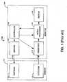
- FIG. 1illustrates a pulse oximetry system 100 having a sensor 110 and a monitor 140 .
- the sensor 110has emitters 120 and a detector 130 and is attached to a patient at a selected fleshy tissue site, such as a thumb or toe.
- the emitters 120project light through the blood vessels and capillaries of the tissue site.
- the detector 130is positioned so as to detect the emitted light as it emerges from the tissue site.
- a pulse oximetry sensoris described in U.S. Patent 6,088,607 entitled "Low Noise Optical Probe," which is assigned to Masimo Corporation, Irvine, CA.
- the monitor 140has drivers 150 , a controller 160 , a front-end 170 , a signal processor 180 , a display 190 .
- the drivers 150alternately activate the emitters 120 as determined by the controller 160 .
- the front-end 170conditions and digitizes the resulting current generated by the detector 130 , which is proportional to the intensity of the detected light.
- the signal processor 180inputs the conditioned detector signal and determines oxygen saturation, as described below, along with pulse rate.
- the display 190provides a numerical readout of a patient's oxygen saturation and pulse rate.
- a pulse oximetry monitoris described in U.S. Patent 5,482,036 entitled “Signal Processing Apparatus and Method," which is assigned to Masimo Corporation, Irvine, CA.
- Other pulse oximetry sensorsare described in US 6 256 523 , WO 97/03603 and US 5 437 275 .
- the Beer-Lambert lawprovides a simple model that describes a tissue site response to pulse oximetry measurements.
- the Beer-Lambert lawstates that the concentration c i of an absorbent in solution can be determined by the intensity of light transmitted through the solution, knowing the mean pathlength, mpl ⁇ , the intensity of the incident light, I 0. ⁇ , and the extinction coefficient, ⁇ i . ⁇ , at a particular wavelength ⁇ .
- HbO 2oxygenated hemoglobin
- Hbreduced hemoglobin
- two discrete wavelengthsare required to solve EQS. 1-2 , e.g. red (RD) and infrared (IR).
- FIG. 2shows a graph 200 depicting the relationship between RD/IR 202 and oxygen saturation (SpO 2 201 , where RD/IR denotes the ratio of the DC normalized, AC detector responses to red and infrared wavelengths, as is well-known in the art and sometimes referred to as the "ratio-of-ratios.”
- This relationshipcan be approximated from Beer-Lambert's Law, described above. However, it is most accurately determined by statistical regression of experimental measurements obtained from human volunteers and calibrated measurements of oxygen saturation.
- the resultcan be depicted as a curve 210 , with measured values of RD/IR shown on an x-axis 202 and corresponding saturation values shown on a y-axis 201 .
- this empirical relationshipcan be stored in a read-only memory (ROM) for use as a look-up table so that SpO 2 can be directly read-out from an input RD/IR measurement.
- ROMread-only memory
- an RD/IR value of 1.0 corresponding to a point 212 on the calibration curve 210indicates a resulting SpO 2 value of approximately 85%.
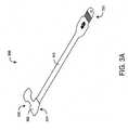
- FIGS. 3A-Billustrate one embodiment of a cyanotic infant sensor.
- the sensorhas a light absorbing surface, as described with respect to FIGS. 4-6 , below.
- the sensoralso has a detector window configured to limit the detector field of view (FOV), as described with respect to FIGS. 7-9 , below.
- FOVdetector field of view
- these featureslimit mean pathlength ratio variations that are particularly manifest in cyanotic patients.
- the sensor emitters and detectorare also matched so as to limit variations in the detector red over IR DC response, i.e. RD DC /IR DC , that are not attributed to variations in the mean pathlength ratio (EQ. 3 ).
- RD DC /IR DCvariations in the mean pathlength ratio
- cyanotic infant sensors 300are constructed so that: ⁇ RD ⁇ c 1 ; ⁇ IR ⁇ c 2 / I O , IR I O , RD ⁇ c 3 ; for i DC RD , i DC IR RD DC / IR DC ⁇ c 4 That is, sensors 300 are constructed from red LEDs and IR LEDs that are each matched as to wavelength (EQ. 4). The LEDs are further matched as to red over IR intensity for given DC drive currents (EQ. 5). In addition, the sensors 300 are constructed from detectors that are matched as to red over IR DC response (EQ. 6).
- the sensor 300has a body 310 physically connecting and providing electrical communication between a sensor head 320 and a connector 330 .
- the sensor head 320houses the emitters and detector and attaches to a patient tissue site.
- the connectormates with a patient cable so as to electrically communicate with a monitor.
- a sensor head surface 324is constructed of light absorbing material.
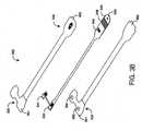
- the sensor 300has a face tape 330 , a flex circuit 340 and a base tape 360 , with the flex circuit 340 disposed between the face tape 330 and the base tape 360 .
- the flex circuit 340has a detector 342 , an emitter 344 with at least two light emitting diodes (LEDs), an information element 346 , and contacts 348 disposed on a connector tab 349 .
- LEDslight emitting diodes
- contacts 348disposed on a connector tab 349 .
- Neonatal sensors having a detector, LEDs, an information element, contacts and connector tabare described in U.S. Patent 6,256,523 entitled "Low-Noise Optical Probes," which is assigned to Masimo Corporation, Irvine, CA.
- the face tape 350 and base tape 360are constructed of Betham tape having attached polyethylene head tapes 351 , 361 .
- the base head tape 361is made of black polyethylene
- the face head tape 351is made of white polyethylene.
- a clear tape layeris disposed on the base head tape 361 tissue side over the detector window 362 .
- the base head tape 361has a detector window 362 and an emitter window 364 each allowing light to pass through the base head tape 361 .
- the base head tape 361has a 4 mil thickness and the flex circuit has a 10 mil thickness. The combined 14 mil material thickness functions to limit the detector FOV, as described with respect to FIGS. 6 and 8 , below.
- FIGS. 4-6illustrate some of the pathlength control aspects of a cyanotic infant sensor 300.
- FIG. 4depicts a fleshy tissue site 10 for sensor attachment, such as a finger or thumb 400 .
- the tissue 10has an epidermis 12 , a dermis 14 , subcutaneous and other soft tissue 16 and bone 18 .
- FIG. 5depicts a conventional pulse oximetry sensor 20 having a detector 22 , an emitter 24 and a tape 26 attached to the fleshy tissue 10 .
- Transmitted light 30 propagating from the emitter 24 to the detector 22 that results in a significant contribution to pulse oximetry measurementspasses through and is absorbed by the pulsatile blood in the dermis 14 .
- a portion of the transmitted light 30is scattered out of the epidermis 12 and reflected by the tape 26 back into the fleshy tissue 10 .
- the detector field-of-view (FOV) 40is relatively wide and, as a result, the detector responds to transmitted light 30 that has propagated, at least in part, outside of the fleshy tissue 10 .
- FOVfield-of-view
- FIG. 6depicts a cyanotic infant sensor 300 that is configured to limit variations in the mean pathlength ratio.
- the sensor 300has a light absorbing tape inner surface 324 that reduces transmitted light reflection back into the tissue site 10, as described with respect to FIGS. 3A-B , above.
- the detector 342has a limited FOV 50 so as to reduce the detection of transmitted light that has propagated outside of the tissue site 10 , as described in detail with respect to FIGS. 7-9 , below.
- FIGS. 8-9illustrate cyanotic infant sensor embodiments having a limited detector field-of-view (FOV).
- FIGS. 7A-Billustrate a conventional sensor 700 having a tape portion 760 , a detector window 762 and a detector 742 having a relatively wide FOV 701. In particular, the window thickness does little to restrict the FOV.
- FIGS. 8 A-Billustrate one embodiment of a cyanotic infant sensor 300 having a material portion 360 , a detector window 362 and a detector 342 having a restricted FOV 801 .
- the material thickness 360functions to define the FOV 801.
- the material thickness 360comprises a flex circuit thickness and a base head tape thickness, as described with respect to FIG. 3B , above.
- FIGA-Billustrate another embodiment of a cyanotic infant sensor 900 having a material portion 960 , a detector window 962 and a detector 942 having a restricted FOV 901 .
- an O-ring 980 deposed around the window 962defines the FOV 901 .
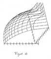
- FIG. 10depicts an exemplar calibration surface 1000 for a cyanotic infant sensor 300 ( FIGS. 3A-B ) calculated along a DC response ratio axis 1001 , a ratio-of-ratios axis 1003 and a resulting oxygen saturation axis 1005 .
- variations in the detector DC response ratio (RD dc /IR dc )are attributed to variations in the mean pathlength ratio (EQ. 3 ).
- a calibration surfaceis determined by statistical regression of experimental measurements obtained from human volunteers and calibrated measurements of oxygen saturation, as is done for a conventional calibration curve ( FIG. 2 ).
- a calculated DC response ratio 1001 in combination with a conventionally calculated ratio-of-ratios 1003is then used to derive an oxygen saturation 1005 for the calibration surface 1000 .
- a cyanotic infant sensorhas been disclosed in detail in connection with various embodiments. These embodiments are disclosed by way of examples only and are not to limit the scope of the claims that follow. One of ordinary skill in art will appreciate many variations and modifications.
Landscapes
- Health & Medical Sciences (AREA)
- Life Sciences & Earth Sciences (AREA)
- Physics & Mathematics (AREA)
- Biomedical Technology (AREA)
- Medical Informatics (AREA)
- Biophysics (AREA)
- Pathology (AREA)
- Engineering & Computer Science (AREA)
- Veterinary Medicine (AREA)
- Heart & Thoracic Surgery (AREA)
- Public Health (AREA)
- Molecular Biology (AREA)
- Surgery (AREA)
- Animal Behavior & Ethology (AREA)
- General Health & Medical Sciences (AREA)
- Optics & Photonics (AREA)
- Spectroscopy & Molecular Physics (AREA)
- Measurement Of The Respiration, Hearing Ability, Form, And Blood Characteristics Of Living Organisms (AREA)
- Investigating Or Analysing Materials By Optical Means (AREA)
Description
- Cyanosis is a congenital condition in which blood pumped to the body contains less than normal amounts of oxygen, resulting in a blue discoloration of the skin. The most common cyanotic condition is tetralogy of Fallot, which is characterized by an abnormal opening, or ventricular septal defect, that allows blood to pass from the right ventricle to the left ventricle without going through the lungs; a narrowing, or stenosis, proximate the pulmonary valve, which partially blocks the flow of blood from the right side of the heart to the lungs; a right ventricle that is abnormally muscular; and an aorta that lies directly over the ventricular septal defect. Another cyanotic condition is tricuspid atresia, characterized by a lack of a tricuspid valve and resulting in a lack of blood flow from the right atrium to the right ventricle. Yet another cyanotic condition is transposition of the great arteries, i.e. the aorta originates from the right ventricle, and the pulmonary artery originates from the left ventricle. Hence, most of the blood returning to the heart from the body is pumped back out without first going to the lungs, and most of the blood returning from the lungs goes back to the lungs.
- Pulse oximetry is a useful tool for diagnosing and evaluating cyanotic conditions. A pulse oximeter performs a spectral analysis of the pulsatile component of arterial blood so as to measure oxygen saturation, the relative concentration of oxygenated hemoglobin, along with pulse rate.
FIG.1 illustrates apulse oximetry system 100 having asensor 110 and amonitor 140. Thesensor 110 hasemitters 120 and adetector 130 and is attached to a patient at a selected fleshy tissue site, such as a thumb or toe. The emitters120 project light through the blood vessels and capillaries of the tissue site. Thedetector 130 is positioned so as to detect the emitted light as it emerges from the tissue site. A pulse oximetry sensor is described inU.S. Patent 6,088,607 entitled "Low Noise Optical Probe," which is assigned to Masimo Corporation, Irvine, CA. - Also shown in
FIG.1 , themonitor 140 hasdrivers 150, acontroller 160, a front-end 170, asignal processor 180, adisplay 190. Thedrivers 150 alternately activate theemitters 120 as determined by thecontroller 160. The front-end 170 conditions and digitizes the resulting current generated by thedetector 130, which is proportional to the intensity of the detected light. Thesignal processor 180 inputs the conditioned detector signal and determines oxygen saturation, as described below, along with pulse rate. Thedisplay 190 provides a numerical readout of a patient's oxygen saturation and pulse rate. A pulse oximetry monitor is described inU.S. Patent 5,482,036 entitled "Signal Processing Apparatus and Method," which is assigned to Masimo Corporation, Irvine, CA. Other pulse oximetry sensors are described inUS 6 256 523 ,WO 97/03603 US 5 437 275 . - The Beer-Lambert law provides a simple model that describes a tissue site response to pulse oximetry measurements. The Beer-Lambert law states that the concentrationci of an absorbent in solution can be determined by the intensity of light transmitted through the solution, knowing the mean pathlength,mplλ, the intensity of the incident light,I0.λ, and the extinction coefficient, εi.λ, at a particular wavelength λ. In generalized form, the Beer-Lambert law is expressed as:


where is the bulk absorption coefficient and represents the probability of absorption per unit length. For conventional pulse oximetry, it is assumed that there are only two significant absorbers, oxygenated hemoglobin (HbO2) and reduced hemoglobin (Hb). Thus, two discrete wavelengths are required to solve EQS.1-2, e.g. red (RD) and infrared (IR). FIG.2 shows agraph 200 depicting the relationship between RD/IR 202 and oxygen saturation (SpO 2201, where RD/IR denotes the ratio of the DC normalized, AC detector responses to red and infrared wavelengths, as is well-known in the art and sometimes referred to as the "ratio-of-ratios." This relationship can be approximated from Beer-Lambert's Law, described above. However, it is most accurately determined by statistical regression of experimental measurements obtained from human volunteers and calibrated measurements of oxygen saturation. The result can be depicted as a curve210, with measured values of RD/IR shown on anx-axis 202 and corresponding saturation values shown on a y-axis 201. In a pulse oximeter device, this empirical relationship can be stored in a read-only memory (ROM) for use as a look-up table so that SpO2 can be directly read-out from an input RD/IR measurement. For example, an RD/IR value of 1.0 corresponding to apoint 212 on the calibration curve210 indicates a resulting SpO2 value of approximately 85%.- Accurate and consistent pulse oximetry measurements on cyanotic infants have been difficult to obtain. An assumption inherent in the calibration curve210 (
FIG.2 ) is that the mean pathlength ratio for RD and IR is constant across the patient population. That is:
However, EQ. 3 may not be valid when cyanotic infants are included in that population. The reason may lie in what has been observed as abnormal tissue tone or lack of firmness associated with cyanotic defects, perhaps due to reduced tissue fiber. Such differences in tissue structure may alter the mean pathlength ratio as compared with normal infants. A cyanotic infant sensor addresses these problems by limiting variations in the RD over IR mean pathlength ratio and/or by providing a mean pathlength ratio measure so as to compensate for such variations. Alone or combined, these sensor apparatus and algorithms increase the accuracy and consistency of pulse oximetry measurements for cyanotic infants. FIG.1 is a block diagram of a prior art pulse oximetry system;FIG.2 is an exemplar graph of a conventional calibration curve;FIGS.3A-B are a perspective and an exploded perspective views, respectively, of a cyanotic infant sensor embodiment;FIGS.4-5 depict cross-sectional views of a tissue site and an attached pulse oximeter sensor, respectively;FIG.6 depicts a cross-sectional view of a tissue site and an attached cyanotic infant sensor;FIGS.7A-B are plan and cross-sectional sensor head views of a conventional pulse oximeter sensor;FIGS.8-9 are plan and cross-sectional sensor head views of cyanotic infant sensor embodiments; andFIG.10 is an exemplar graph of a calibration surface incorporating a mean pathlength ratio measure.FIGS.3A-B illustrate one embodiment of a cyanotic infant sensor. The sensor has a light absorbing surface, as described with respect toFIGS.4-6 , below. The sensor also has a detector window configured to limit the detector field of view (FOV), as described with respect toFIGS.7-9 , below. Advantageously, these features limit mean pathlength ratio variations that are particularly manifest in cyanotic patients.- The sensor emitters and detector are also matched so as to limit variations in the detector red over IR DC response, i.e. RDDC/IRDC, that are not attributed to variations in the mean pathlength ratio (EQ.3). Such matching advantageously allows for measurement and calibration of the mean pathlength ratio, as described with respect to
FIG.10 , below. In one embodiment,cyanotic infant sensors 300 are constructed so that:


That is,sensors 300 are constructed from red LEDs and IR LEDs that are each matched as to wavelength (EQ. 4). The LEDs are further matched as to red over IR intensity for given DC drive currents (EQ. 5). In addition, thesensors 300 are constructed from detectors that are matched as to red over IR DC response (EQ. 6). - As shown in
FIG.3A , thesensor 300 has abody 310 physically connecting and providing electrical communication between asensor head 320 and aconnector 330. Thesensor head 320 houses the emitters and detector and attaches to a patient tissue site. The connector mates with a patient cable so as to electrically communicate with a monitor. In one embodiment, asensor head surface 324 is constructed of light absorbing material. - As shown in
FIG.3B , thesensor 300 has aface tape 330, aflex circuit 340 and abase tape 360, with theflex circuit 340 disposed between theface tape 330 and thebase tape 360. Theflex circuit 340 has adetector 342, anemitter 344 with at least two light emitting diodes (LEDs), aninformation element 346, andcontacts 348 disposed on aconnector tab 349. Neonatal sensors having a detector, LEDs, an information element, contacts and connector tab are described inU.S. Patent 6,256,523 entitled "Low-Noise Optical Probes," which is assigned to Masimo Corporation, Irvine, CA. In one embodiment, theface tape 350 andbase tape 360 are constructed of Betham tape having attachedpolyethylene head tapes base head tape 361 is made of black polyethylene, and theface head tape 351 is made of white polyethylene. In one embodiment, a clear tape layer is disposed on thebase head tape 361 tissue side over thedetector window 362. Thebase head tape 361 has adetector window 362 and anemitter window 364 each allowing light to pass through thebase head tape 361. In one embodiment, thebase head tape 361 has a 4 mil thickness and the flex circuit has a 10 mil thickness. The combined 14 mil material thickness functions to limit the detector FOV, as described with respect toFIGS.6 and8 , below. FIGS.4-6 illustrate some of the pathlength control aspects of acyanotic infant sensor 300.FIG.4 depicts afleshy tissue site 10 for sensor attachment, such as a finger or thumb400. Thetissue 10 has anepidermis 12, adermis 14, subcutaneous and othersoft tissue 16 andbone 18.FIG.5 depicts a conventionalpulse oximetry sensor 20 having adetector 22, anemitter 24 and atape 26 attached to thefleshy tissue 10. Transmitted light30 propagating from theemitter 24 to thedetector 22 that results in a significant contribution to pulse oximetry measurements passes through and is absorbed by the pulsatile blood in thedermis 14. A portion of the transmittedlight 30 is scattered out of theepidermis 12 and reflected by thetape 26 back into thefleshy tissue 10. The detector field-of-view (FOV) 40 is relatively wide and, as a result, the detector responds to transmitted light30 that has propagated, at least in part, outside of thefleshy tissue 10.FIG.6 depicts acyanotic infant sensor 300 that is configured to limit variations in the mean pathlength ratio. In particular, thesensor 300 has a light absorbing tapeinner surface 324 that reduces transmitted light reflection back into thetissue site 10, as described with respect toFIGS.3A-B , above. Further, thedetector 342 has alimited FOV 50 so as to reduce the detection of transmitted light that has propagated outside of thetissue site 10, as described in detail with respect toFIGS.7-9 , below.FIGS.8-9 illustrate cyanotic infant sensor embodiments having a limited detector field-of-view (FOV).FIGS.7A-B illustrate aconventional sensor 700 having atape portion 760, adetector window 762 and adetector 742 having a relativelywide FOV 701. In particular, the window thickness does little to restrict the FOV.FIGS. 8A-B illustrate one embodiment of acyanotic infant sensor 300 having amaterial portion 360, adetector window 362 and adetector 342 having a restrictedFOV 801. In particular, thematerial thickness 360 functions to define theFOV 801. In one embodiment, thematerial thickness 360 comprises a flex circuit thickness and a base head tape thickness, as described with respect toFIG.3B , above.FIGS.9A-B illustrate another embodiment of acyanotic infant sensor 900 having amaterial portion 960, adetector window 962 and adetector 942 having a restrictedFOV 901. In particular, an O-ring 980 deposed around thewindow 962 defines theFOV 901.FIG.10 depicts an exemplar calibration surface1000 for a cyanotic infant sensor300 (FIGS.3A-B ) calculated along a DC response ratio axis1001, a ratio-of-ratios axis1003 and a resulting oxygen saturation axis1005. Matching the emitters and detectors, as described with respect toFIG3A , above, allows for pathlength calibration. In particular, variations in the detector DC response ratio (RDdc/IRdc) are attributed to variations in the mean pathlength ratio (EQ.3). As such, a calibration surface is determined by statistical regression of experimental measurements obtained from human volunteers and calibrated measurements of oxygen saturation, as is done for a conventional calibration curve (FIG.2 ). A calculated DC response ratio1001 in combination with a conventionally calculated ratio-of-ratios1003 is then used to derive an oxygen saturation1005 for the calibration surface1000.- A cyanotic infant sensor has been disclosed in detail in connection with various embodiments. These embodiments are disclosed by way of examples only and are not to limit the scope of the claims that follow. One of ordinary skill in art will appreciate many variations and modifications.


Claims (4)
- A pulse oximetry sensor (300) comprising:a plurality of emitters (344) configured to transmit light having a plurality of wavelengths into a fleshy medium; the transmitted light being red and infrared light;at least one detector (342) responsive to said light after absorption by constituents of pulsatile blood flowing within said medium so as to generate a plurality of intensity signals;a flexible sensor head (320) housing said emitters and said at least one detector and comprising a flexible tape material (361) configured to position the emitters and detector on said fleshy medium by substantially conforming to a shape of said fleshy medium, said head having a light absorbing surface (324) adapted to be disposed proximate said medium, said light absorbing surface configured to reduce reflection of the transmitted light off of the flexible tape back into the fleshy medium;a detector window (362) defined by said sensor head flexible tape material and by said light absorbing surface, so as to limit the field-of-view of said at least one detector.
- The pulse oximetry sensor according to claim 1 wherein said sensor head is configured to attach to a human digit with said light absorbing surface disposed around the periphery of the digit so as to at least partially absorb emitter transmitted light that is scattered out of said digit.
- The pulse oximetry sensor according to claim 2 wherein a material thickness of said sensor head proximate said detector window limits the field-of-view of said at least one detector.
- The pulse oximetry sensor according to claim 2 further comprising an O-ring (962) disposed around the periphery of said detector window so as to limit the field-of-view of said at least one detector.
Applications Claiming Priority (2)
| Application Number | Priority Date | Filing Date | Title |
|---|---|---|---|
| US58628104P | 2004-07-09 | 2004-07-09 | |
| PCT/US2005/024088WO2006017117A2 (en) | 2004-07-09 | 2005-07-07 | Cyanotic infant sensor |
Publications (2)
| Publication Number | Publication Date |
|---|---|
| EP1771109A2 EP1771109A2 (en) | 2007-04-11 |
| EP1771109B1true EP1771109B1 (en) | 2014-04-16 |
Family
ID=35124333
Family Applications (1)
| Application Number | Title | Priority Date | Filing Date |
|---|---|---|---|
| EP05772104.5AExpired - LifetimeEP1771109B1 (en) | 2004-07-09 | 2005-07-07 | Cyanotic infant sensor |
Country Status (3)
| Country | Link |
|---|---|
| EP (1) | EP1771109B1 (en) |
| JP (1) | JP2008505706A (en) |
| WO (1) | WO2006017117A2 (en) |
Families Citing this family (10)
| Publication number | Priority date | Publication date | Assignee | Title |
|---|---|---|---|---|
| US7647083B2 (en) | 2005-03-01 | 2010-01-12 | Masimo Laboratories, Inc. | Multiple wavelength sensor equalization |
| US8265723B1 (en) | 2006-10-12 | 2012-09-11 | Cercacor Laboratories, Inc. | Oximeter probe off indicator defining probe off space |
| US8374665B2 (en) | 2007-04-21 | 2013-02-12 | Cercacor Laboratories, Inc. | Tissue profile wellness monitor |
| US20100004518A1 (en) | 2008-07-03 | 2010-01-07 | Masimo Laboratories, Inc. | Heat sink for noninvasive medical sensor |
| US8515509B2 (en) | 2008-08-04 | 2013-08-20 | Cercacor Laboratories, Inc. | Multi-stream emitter for noninvasive measurement of blood constituents |
| US9839381B1 (en) | 2009-11-24 | 2017-12-12 | Cercacor Laboratories, Inc. | Physiological measurement system with automatic wavelength adjustment |
| WO2011069122A1 (en) | 2009-12-04 | 2011-06-09 | Masimo Corporation | Calibration for multi-stage physiological monitors |
| JP2019217151A (en)* | 2018-06-22 | 2019-12-26 | 京セラ株式会社 | Measuring device, measuring method and measuring program |
| WO2021146333A1 (en) | 2020-01-13 | 2021-07-22 | Masimo Corporation | Wearable device with physiological parameters monitoring |
| EP4370022A1 (en) | 2021-07-13 | 2024-05-22 | Masimo Corporation | Wearable device with physiological parameters monitoring |
Family Cites Families (6)
| Publication number | Priority date | Publication date | Assignee | Title |
|---|---|---|---|---|
| US5638818A (en)* | 1991-03-21 | 1997-06-17 | Masimo Corporation | Low noise optical probe |
| US5437275A (en)* | 1994-02-02 | 1995-08-01 | Biochem International Inc. | Pulse oximetry sensor |
| WO1997003603A1 (en)* | 1995-07-21 | 1997-02-06 | Respironics, Inc. | Method and apparatus for diode laser pulse oximetry using multifiber optical cables and disposable fiber optic probes |
| US5797841A (en)* | 1996-03-05 | 1998-08-25 | Nellcor Puritan Bennett Incorporated | Shunt barrier in pulse oximeter sensor |
| US6466809B1 (en)* | 2000-11-02 | 2002-10-15 | Datex-Ohmeda, Inc. | Oximeter sensor having laminated housing with flat patient interface surface |
| US6985764B2 (en)* | 2001-05-03 | 2006-01-10 | Masimo Corporation | Flex circuit shielded optical sensor |
- 2005
- 2005-07-07EPEP05772104.5Apatent/EP1771109B1/ennot_activeExpired - Lifetime
- 2005-07-07WOPCT/US2005/024088patent/WO2006017117A2/enactiveApplication Filing
- 2005-07-07JPJP2007520497Apatent/JP2008505706A/enactivePending
Also Published As
| Publication number | Publication date |
|---|---|
| EP1771109A2 (en) | 2007-04-11 |
| WO2006017117A2 (en) | 2006-02-16 |
| JP2008505706A (en) | 2008-02-28 |
| WO2006017117A3 (en) | 2006-06-08 |
Similar Documents
| Publication | Publication Date | Title |
|---|---|---|
| US7937128B2 (en) | Cyanotic infant sensor | |
| US6421549B1 (en) | Adaptive calibration pulsed oximetry method and device | |
| US6760609B2 (en) | Adaptive calibration pulsed oximetry method and device | |
| US7274955B2 (en) | Parameter compensated pulse oximeter | |
| EP1322216B1 (en) | A pulse oximeter and a method of its operation | |
| US7142901B2 (en) | Parameter compensated physiological monitor | |
| EP2286721B1 (en) | Physiological Parameter Confidence Measure | |
| KR100376649B1 (en) | Oxygen Saturation Meters and Sensors Optimized for Low Saturation | |
| EP0850013B1 (en) | Procedure for the determination of fractional oxygen saturation | |
| EP0613652B1 (en) | Apparatus and method for non-invasive measurement of oxygen saturation | |
| US6771994B2 (en) | Pulse oximeter probe-off detection system | |
| US20080004513A1 (en) | VCSEL Tissue Spectrometer | |
| US20120323095A1 (en) | Method for detection of aberrant tissue spectra | |
| US20080221463A1 (en) | System and method for venous pulsation detection using near infrared wavelengths | |
| US20230320634A1 (en) | System for monitoring fetal status during child birth | |
| EP1771109B1 (en) | Cyanotic infant sensor | |
| Reuss et al. | The pulse in reflectance pulse oximetry: modeling and experimental studies | |
| US20090030296A1 (en) | Predictive oximetry model and method |
Legal Events
| Date | Code | Title | Description |
|---|---|---|---|
| PUAI | Public reference made under article 153(3) epc to a published international application that has entered the european phase | Free format text:ORIGINAL CODE: 0009012 | |
| 17P | Request for examination filed | Effective date:20070119 | |
| AK | Designated contracting states | Kind code of ref document:A2 Designated state(s):AT BE BG CH CY CZ DE DK EE ES FI FR GB GR HU IE IS IT LI LT LU LV MC NL PL PT RO SE SI SK TR | |
| DAX | Request for extension of the european patent (deleted) | ||
| 17Q | First examination report despatched | Effective date:20100608 | |
| REG | Reference to a national code | Ref country code:DE Ref legal event code:R079 Ref document number:602005043308 Country of ref document:DE Free format text:PREVIOUS MAIN CLASS: A61B0005000000 Ipc:A61B0005145500 | |
| GRAP | Despatch of communication of intention to grant a patent | Free format text:ORIGINAL CODE: EPIDOSNIGR1 | |
| RIC1 | Information provided on ipc code assigned before grant | Ipc:A61B 5/1455 20060101AFI20130926BHEP Ipc:A61B 5/00 20060101ALI20130926BHEP | |
| INTG | Intention to grant announced | Effective date:20131030 | |
| GRAS | Grant fee paid | Free format text:ORIGINAL CODE: EPIDOSNIGR3 | |
| GRAA | (expected) grant | Free format text:ORIGINAL CODE: 0009210 | |
| AK | Designated contracting states | Kind code of ref document:B1 Designated state(s):AT BE BG CH CY CZ DE DK EE ES FI FR GB GR HU IE IS IT LI LT LU LV MC NL PL PT RO SE SI SK TR | |
| REG | Reference to a national code | Ref country code:GB Ref legal event code:FG4D | |
| REG | Reference to a national code | Ref country code:CH Ref legal event code:EP | |
| REG | Reference to a national code | Ref country code:AT Ref legal event code:REF Ref document number:662015 Country of ref document:AT Kind code of ref document:T Effective date:20140515 | |
| REG | Reference to a national code | Ref country code:IE Ref legal event code:FG4D | |
| REG | Reference to a national code | Ref country code:DE Ref legal event code:R096 Ref document number:602005043308 Country of ref document:DE Effective date:20140528 | |
| REG | Reference to a national code | Ref country code:AT Ref legal event code:MK05 Ref document number:662015 Country of ref document:AT Kind code of ref document:T Effective date:20140416 | |
| REG | Reference to a national code | Ref country code:NL Ref legal event code:VDEP Effective date:20140416 | |
| REG | Reference to a national code | Ref country code:LT Ref legal event code:MG4D | |
| PG25 | Lapsed in a contracting state [announced via postgrant information from national office to epo] | Ref country code:NL Free format text:LAPSE BECAUSE OF FAILURE TO SUBMIT A TRANSLATION OF THE DESCRIPTION OR TO PAY THE FEE WITHIN THE PRESCRIBED TIME-LIMIT Effective date:20140416 Ref country code:CY Free format text:LAPSE BECAUSE OF FAILURE TO SUBMIT A TRANSLATION OF THE DESCRIPTION OR TO PAY THE FEE WITHIN THE PRESCRIBED TIME-LIMIT Effective date:20140416 Ref country code:IS Free format text:LAPSE BECAUSE OF FAILURE TO SUBMIT A TRANSLATION OF THE DESCRIPTION OR TO PAY THE FEE WITHIN THE PRESCRIBED TIME-LIMIT Effective date:20140816 Ref country code:LT Free format text:LAPSE BECAUSE OF FAILURE TO SUBMIT A TRANSLATION OF THE DESCRIPTION OR TO PAY THE FEE WITHIN THE PRESCRIBED TIME-LIMIT Effective date:20140416 Ref country code:GR Free format text:LAPSE BECAUSE OF FAILURE TO SUBMIT A TRANSLATION OF THE DESCRIPTION OR TO PAY THE FEE WITHIN THE PRESCRIBED TIME-LIMIT Effective date:20140717 Ref country code:BG Free format text:LAPSE BECAUSE OF FAILURE TO SUBMIT A TRANSLATION OF THE DESCRIPTION OR TO PAY THE FEE WITHIN THE PRESCRIBED TIME-LIMIT Effective date:20140716 Ref country code:FI Free format text:LAPSE BECAUSE OF FAILURE TO SUBMIT A TRANSLATION OF THE DESCRIPTION OR TO PAY THE FEE WITHIN THE PRESCRIBED TIME-LIMIT Effective date:20140416 | |
| PG25 | Lapsed in a contracting state [announced via postgrant information from national office to epo] | Ref country code:SE Free format text:LAPSE BECAUSE OF FAILURE TO SUBMIT A TRANSLATION OF THE DESCRIPTION OR TO PAY THE FEE WITHIN THE PRESCRIBED TIME-LIMIT Effective date:20140416 Ref country code:AT Free format text:LAPSE BECAUSE OF FAILURE TO SUBMIT A TRANSLATION OF THE DESCRIPTION OR TO PAY THE FEE WITHIN THE PRESCRIBED TIME-LIMIT Effective date:20140416 Ref country code:LV Free format text:LAPSE BECAUSE OF FAILURE TO SUBMIT A TRANSLATION OF THE DESCRIPTION OR TO PAY THE FEE WITHIN THE PRESCRIBED TIME-LIMIT Effective date:20140416 Ref country code:ES Free format text:LAPSE BECAUSE OF FAILURE TO SUBMIT A TRANSLATION OF THE DESCRIPTION OR TO PAY THE FEE WITHIN THE PRESCRIBED TIME-LIMIT Effective date:20140416 Ref country code:PL Free format text:LAPSE BECAUSE OF FAILURE TO SUBMIT A TRANSLATION OF THE DESCRIPTION OR TO PAY THE FEE WITHIN THE PRESCRIBED TIME-LIMIT Effective date:20140416 | |
| PG25 | Lapsed in a contracting state [announced via postgrant information from national office to epo] | Ref country code:PT Free format text:LAPSE BECAUSE OF FAILURE TO SUBMIT A TRANSLATION OF THE DESCRIPTION OR TO PAY THE FEE WITHIN THE PRESCRIBED TIME-LIMIT Effective date:20140818 | |
| REG | Reference to a national code | Ref country code:DE Ref legal event code:R097 Ref document number:602005043308 Country of ref document:DE | |
| PG25 | Lapsed in a contracting state [announced via postgrant information from national office to epo] | Ref country code:RO Free format text:LAPSE BECAUSE OF FAILURE TO SUBMIT A TRANSLATION OF THE DESCRIPTION OR TO PAY THE FEE WITHIN THE PRESCRIBED TIME-LIMIT Effective date:20140416 Ref country code:SK Free format text:LAPSE BECAUSE OF FAILURE TO SUBMIT A TRANSLATION OF THE DESCRIPTION OR TO PAY THE FEE WITHIN THE PRESCRIBED TIME-LIMIT Effective date:20140416 Ref country code:DK Free format text:LAPSE BECAUSE OF FAILURE TO SUBMIT A TRANSLATION OF THE DESCRIPTION OR TO PAY THE FEE WITHIN THE PRESCRIBED TIME-LIMIT Effective date:20140416 Ref country code:CZ Free format text:LAPSE BECAUSE OF FAILURE TO SUBMIT A TRANSLATION OF THE DESCRIPTION OR TO PAY THE FEE WITHIN THE PRESCRIBED TIME-LIMIT Effective date:20140416 Ref country code:EE Free format text:LAPSE BECAUSE OF FAILURE TO SUBMIT A TRANSLATION OF THE DESCRIPTION OR TO PAY THE FEE WITHIN THE PRESCRIBED TIME-LIMIT Effective date:20140416 Ref country code:BE Free format text:LAPSE BECAUSE OF FAILURE TO SUBMIT A TRANSLATION OF THE DESCRIPTION OR TO PAY THE FEE WITHIN THE PRESCRIBED TIME-LIMIT Effective date:20140416 | |
| PLBE | No opposition filed within time limit | Free format text:ORIGINAL CODE: 0009261 | |
| STAA | Information on the status of an ep patent application or granted ep patent | Free format text:STATUS: NO OPPOSITION FILED WITHIN TIME LIMIT | |
| PG25 | Lapsed in a contracting state [announced via postgrant information from national office to epo] | Ref country code:LU Free format text:LAPSE BECAUSE OF FAILURE TO SUBMIT A TRANSLATION OF THE DESCRIPTION OR TO PAY THE FEE WITHIN THE PRESCRIBED TIME-LIMIT Effective date:20140707 | |
| REG | Reference to a national code | Ref country code:CH Ref legal event code:PL | |
| 26N | No opposition filed | Effective date:20150119 | |
| PG25 | Lapsed in a contracting state [announced via postgrant information from national office to epo] | Ref country code:IT Free format text:LAPSE BECAUSE OF FAILURE TO SUBMIT A TRANSLATION OF THE DESCRIPTION OR TO PAY THE FEE WITHIN THE PRESCRIBED TIME-LIMIT Effective date:20140416 | |
| REG | Reference to a national code | Ref country code:IE Ref legal event code:MM4A | |
| PG25 | Lapsed in a contracting state [announced via postgrant information from national office to epo] | Ref country code:LI Free format text:LAPSE BECAUSE OF NON-PAYMENT OF DUE FEES Effective date:20140731 Ref country code:CH Free format text:LAPSE BECAUSE OF NON-PAYMENT OF DUE FEES Effective date:20140731 | |
| REG | Reference to a national code | Ref country code:DE Ref legal event code:R097 Ref document number:602005043308 Country of ref document:DE Effective date:20150119 | |
| PG25 | Lapsed in a contracting state [announced via postgrant information from national office to epo] | Ref country code:SI Free format text:LAPSE BECAUSE OF FAILURE TO SUBMIT A TRANSLATION OF THE DESCRIPTION OR TO PAY THE FEE WITHIN THE PRESCRIBED TIME-LIMIT Effective date:20140416 | |
| PG25 | Lapsed in a contracting state [announced via postgrant information from national office to epo] | Ref country code:IE Free format text:LAPSE BECAUSE OF NON-PAYMENT OF DUE FEES Effective date:20140707 | |
| PG25 | Lapsed in a contracting state [announced via postgrant information from national office to epo] | Ref country code:MC Free format text:LAPSE BECAUSE OF FAILURE TO SUBMIT A TRANSLATION OF THE DESCRIPTION OR TO PAY THE FEE WITHIN THE PRESCRIBED TIME-LIMIT Effective date:20140416 | |
| REG | Reference to a national code | Ref country code:FR Ref legal event code:PLFP Year of fee payment:12 | |
| PG25 | Lapsed in a contracting state [announced via postgrant information from national office to epo] | Ref country code:TR Free format text:LAPSE BECAUSE OF FAILURE TO SUBMIT A TRANSLATION OF THE DESCRIPTION OR TO PAY THE FEE WITHIN THE PRESCRIBED TIME-LIMIT Effective date:20140416 Ref country code:HU Free format text:LAPSE BECAUSE OF FAILURE TO SUBMIT A TRANSLATION OF THE DESCRIPTION OR TO PAY THE FEE WITHIN THE PRESCRIBED TIME-LIMIT; INVALID AB INITIO Effective date:20050707 | |
| REG | Reference to a national code | Ref country code:FR Ref legal event code:PLFP Year of fee payment:13 | |
| REG | Reference to a national code | Ref country code:FR Ref legal event code:PLFP Year of fee payment:14 | |
| P01 | Opt-out of the competence of the unified patent court (upc) registered | Effective date:20230601 | |
| PGFP | Annual fee paid to national office [announced via postgrant information from national office to epo] | Ref country code:GB Payment date:20240516 Year of fee payment:20 | |
| PGFP | Annual fee paid to national office [announced via postgrant information from national office to epo] | Ref country code:FR Payment date:20240509 Year of fee payment:20 | |
| PGFP | Annual fee paid to national office [announced via postgrant information from national office to epo] | Ref country code:DE Payment date:20240514 Year of fee payment:20 | |
| REG | Reference to a national code | Ref country code:DE Ref legal event code:R071 Ref document number:602005043308 Country of ref document:DE | |
| REG | Reference to a national code | Ref country code:GB Ref legal event code:PE20 Expiry date:20250706 |