EP1769761B1 - Bone anchoring device - Google Patents
Bone anchoring deviceDownload PDFInfo
- Publication number
- EP1769761B1 EP1769761B1EP07001171AEP07001171AEP1769761B1EP 1769761 B1EP1769761 B1EP 1769761B1EP 07001171 AEP07001171 AEP 07001171AEP 07001171 AEP07001171 AEP 07001171AEP 1769761 B1EP1769761 B1EP 1769761B1
- Authority
- EP
- European Patent Office
- Prior art keywords
- rod
- anchoring device
- recess
- legs
- receiving portion
- Prior art date
- Legal status (The legal status is an assumption and is not a legal conclusion. Google has not performed a legal analysis and makes no representation as to the accuracy of the status listed.)
- Expired - Lifetime
Links
Images


Classifications
- A—HUMAN NECESSITIES
- A61—MEDICAL OR VETERINARY SCIENCE; HYGIENE
- A61B—DIAGNOSIS; SURGERY; IDENTIFICATION
- A61B17/00—Surgical instruments, devices or methods
- A61B17/56—Surgical instruments or methods for treatment of bones or joints; Devices specially adapted therefor
- A61B17/58—Surgical instruments or methods for treatment of bones or joints; Devices specially adapted therefor for osteosynthesis, e.g. bone plates, screws or setting implements
- A61B17/68—Internal fixation devices, including fasteners and spinal fixators, even if a part thereof projects from the skin
- A61B17/70—Spinal positioners or stabilisers, e.g. stabilisers comprising fluid filler in an implant
- A61B17/7001—Screws or hooks combined with longitudinal elements which do not contact vertebrae
- A61B17/7032—Screws or hooks with U-shaped head or back through which longitudinal rods pass
- A—HUMAN NECESSITIES
- A61—MEDICAL OR VETERINARY SCIENCE; HYGIENE
- A61B—DIAGNOSIS; SURGERY; IDENTIFICATION
- A61B17/00—Surgical instruments, devices or methods
- A61B17/56—Surgical instruments or methods for treatment of bones or joints; Devices specially adapted therefor
- A61B17/58—Surgical instruments or methods for treatment of bones or joints; Devices specially adapted therefor for osteosynthesis, e.g. bone plates, screws or setting implements
- A61B17/68—Internal fixation devices, including fasteners and spinal fixators, even if a part thereof projects from the skin
- A61B17/70—Spinal positioners or stabilisers, e.g. stabilisers comprising fluid filler in an implant
- A61B17/7001—Screws or hooks combined with longitudinal elements which do not contact vertebrae
- A61B17/7035—Screws or hooks, wherein a rod-clamping part and a bone-anchoring part can pivot relative to each other
- A61B17/7037—Screws or hooks, wherein a rod-clamping part and a bone-anchoring part can pivot relative to each other wherein pivoting is blocked when the rod is clamped
Definitions
- the inventionrelates to a bone anchoring device comprising an anchoring element which has a shank to be anchored in a bone and a head, a receiving portion to receive said head for the connection with a rod and a pressure element which exerts pressure on said head and with various closure elements cooperating with said receiving portion to secure the rod in the receiving portion.
- US 5,443,467discloses a bone screw comprising a receiver member and a screw member having a threaded portion and a head.
- a pressure diskis slidable within the receiver member and acts onto the head.
- the rodis placed on top of the pressure disk and the arrangement is locked by means of a rod locking nut and a lock nut exerting pressure onto the rod which then exerts pressure on the pressure disk, thus locking the head.
- US 6,063,090discloses a spinal fixation system with a pedicle screw and a retainer head to connect the pedicle screw with a longitudinal support.
- An insert 12is provided with exerts a pressure onto the head of the pedicle screw which is accommodated in the retainer head.
- Tension meansare provided to press onto the insert to lock the head of the pedicle screw in its polyaxial position and to fix the longitudinal support.
- the rod and the head of the bone screwmay be separately fastened.
- US 2003/0100896 A1discloses an element with a shank and a holding element connected to it for connecting to a rod, wherein the holding element has a recess having a U-shaped cross-section for receiving the rod with two open legs and an inner thread on the open legs and a locking element with an outer thread which cooperates with the inner thread of the legs.
- the holding elementis polyaxially connected with the head of a bone screw.
- a pressure diskis provided which acts on the head when pressure is exerted onto the rod by means of an inner screw.
- the headcan be locked independently from the fixation of the rod. If the two types of anchoring devices shall be used simultaneously during surgery it is necessary to have the different types of anchoring devices separately on stock or to pre-assemble the preferred anchoring device with the required pressure disk and/or the pressure element before or during surgery.
- US 2004/018647381discloses a bone anchoring device with a bone anchoring element which is polyaxially connected to a receiving portion and a pressure element to exert pressure onto the head to lock the head in its position wherein an inner screw is provided which can be screwed in the receiving portion to exert a pressure on the rod.
- the inner threadends above the rod when the rod is inserted and an undercut is provided to allow a design of the receiving portion to be smaller in its dimensions.
- US 2005/0055026 A1describes an anchoring element comprising a screw having a shank with a bone thread portion and a head, and comprising a receiving part for connecting the screw to a rod-shaped element, the screw and the receiving part being connected to one another in a polyaxial or monoaxial manner, and the shank of the screw being of tubular design and its wall having a plurality of recesses.
- the anchoring elementcomprises a closure device consisting of a nut and an inner screw for independently fixing the head and the rod.
- the closure deviceconsists only of an inner screw for simultaneously fixing the head and the rod.
- US 2002/0082602 A1describes a bone screw with a thread section and a receiving part for receiving a rod to begin connected to the bone screw.
- the connection and locking of the connection between the bone screw and the rodtakes place via an outer nut.
- US 2004/0186474 A1discloses an implant having a shaft and a holding element connected therewith for connection with a rod.
- a recess with a U-shaped cross section for accommodation of the rodis provided in the holding element and a closure element fixes the rod inserted into the U-shaped recess.
- An abutmentis provided at or in the holding element to limit tilting of the closure element about the rod at the time of final tightening of the closure element in the holding element.
- the bone anchoring element according to the inventionhas the advantage that it can be used with the choice of a closure element in two ways. If a single part closure element is selected, it is possible to simultaneously lock the head in its polyaxial position and to fix the rod. If a two part closure element is selected, it is possible to separately lock the head and to fix the rod. For both applications only one single receiving portion and pressure element is necessary. Therefore, the surgeon can use one bone anchoring device and can select during surgery which kind of closure mechanism shall be used.
- the bone anchoring deviceis compact in size, since it is not necessary to use an outer nut or ring to prevent splaying of the legs. Also, the wall thickness of the receiving portion is such that there are no thinned inner portions like thread runouts or undercuts that would weaken the structure.
- Fig. 1shows an exploded perspective view of the bone anchoring device with a single part closure element.
- Fig. 2shows a cross-sectional view of the bone anchoring device according to Fig. 1 .
- Fig. 3shows a perspective view of the bone anchoring device of Fig. 1 .
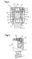
- Fig. 4shows a cross-sectional view of a bone anchoring device with a two part closure element.
- Fig. 5shows a perspective view of the bone anchoring device of Fig. 4 .
- Fig. 6shows possibilities of use of the bone anchoring device with a single part closure element and a two part closure element.
- Fig. 7ashows in a schematic way the locking mechanism of the bone anchoring device with the single part closure element.
- Fig. 7bshows in a schematic manner the locking mechanism of the two part closure mechanism.
- a first embodiment of the bone anchoring deviceincludes a bone screw 1 having a shank 2 with a bone thread and a spherical segment-shaped head 3 which has a recess 4 for engagement with a screwing-in tool.
- the bone anchoring devicefurther comprises a receiving portion 5 which is substantially cylindrical and has a first end 6 and a second end 7 opposite to the first end. The two ends are perpendicular to a longitudinal axis 8.
- a first bore 9is provided which extends from the first end 6 to a predetermined distance from the second end 7.
- an opening 10is provided the diameter of which is smaller than the diameter of the bore 9.
- the coaxial bore 9tapers towards the opening 10.
- the diameter of the coaxial bore 9is in the embodiment shown slightly larger than the largest diameter of the head 3, so that the bone screw 1 can be guided through the bore 9 with the shank 2 extending through the opening 10 and the head 3 resting against the spherically shaped section 11.
- the receiving portion 5further has a U-shaped recess 12 which starts at the first end 6 and extends in the direction of the second end 7 so that the bottom 13 of the U-shaped recess has a distance d from the second end 7.
- the width of the U-shaped recess 12 in the lateral direction perpendicular to the longitudinal axis 8is slightly larger than the diameter of a rod 14 which is to be received in the U-shaped recess.
- two free legs 15, 16are formed ending towards the first end 6.
- Adjacent to the first end 6 the receiving portioncomprises an inner thread 17 at the legs 15, 16.
- a second coaxial bore 18is provided adjacent to the first end 6 which has a diameter larger than the diameter of the first coaxial bore 9 so that a shoulder 9a is formed at the transition from the first bore 9 to the second bore 18.
- the inner diameter of the coaxial bore 18 and the inner diameter between opposing crests of the inner thread 17is substantially the same.
- the thread 17opens out into the U-shaped recess 12. Therefore,there is no thread runout and also no undercut. In an assembled state, when the rod 14 is inserted into the receiving portion 5 the inner thread 17 ends at a position at said legs 15, 16 which is above the upper surface of the rod 14.
- a pressure element 20which has a substantially cylindrical construction with a first end 21 and a second end 22 opposite to the first end.
- the outer diameteris only slightly smaller than the inner diameter of the first coaxial bore 9 to allow the pressure element to be introduced into the bore 9 of the receiving portion 5 and to be moved in an axial direction.
- the pressure element 20Adjacent to its second end which faces the head 3 in an assembled state, the pressure element 20 comprises a spherical recess 23 the radius of which corresponds to the radius of the spherical head 3.
- Adjacent to its first end 21 the pressure elementAdjacent to its first end 21 the pressure element has a U-shaped recess 24 which extends transversely to the longitudinal axis 8.
- this U-shaped recess 24is selected such that the rod 14 which is to be received in the receiving portion 5 can be inserted into the recess 24 and guided laterally therein.
- the open legs 25, 26 of the pressure element 20are formed ending towards the first end 21.
- the depth of the U-shaped recess 24 seen in the direction of the longitudinal axis 8 of the receiving portion 5is larger than the diameter of the rod 14 to be received such that the legs 25, 26 project over the rod when the rod rests on the bottom 27 of the U-shaped recess 24.
- the pressure element 20further comprises a coaxial bore 28 to allow for accessing the bone screw 1 with a screw driver.
- the pressure element 20comprises adjacent to its first end 21 a circumferential projection 29 at said legs 25, 26 the outer diameter of which is slightly smaller than the inner diameter of the second coaxial bore 18 of the receiving portion 5 in such a manner that the pressure element 20 can slide with the circumferential projection 21 in the second coaxial bore 18.
- the bone anchoring devicefurther comprises a closure element which in this embodiment is a single part closure element in form of an inner screw 30.
- the outer thread of the inner screw 30cooperates with the inner thread 17 provided at the legs 15, 16.
- the inner screw 30has a recess 31 for engagement with a screwing-in tool.
- the inner screwhas a first cylindrical projection 32 the diameter of which is just as large that the cylindrical projection 32 slides along the inner wall of the second coaxial bore 18 when the inner screw 30 is screwed-in between the legs 25, 26.
- the first cylindrical projection 32tapers into a second cylindrical projection 33 having a diameter which is larger than the diameter of the rod but smaller than the diameter of the second bore 18 and which engages in an assembled state shown in Fig. 2 with a corresponding circular recess 34 adjacent to the first end 21 of the pressure element 20.
- the free end surface of the second projection 33is flat.
- the dimensions of the pressure element 20 relative to the head 3 of the bone screw and to the receiving portion 5are such that in a state in which the bone screw is not yet locked in its final polyaxial position relative to the receiving portion 5 the bottom 27 of the U-shaped recess 24 of the pressure element 20 has a distance from the second end 7 of the receiving portion which is greater than the distance d shown in Fig. 1 so that it projects above the bottom 13 of the U-shaped recess 12 of the receiving portion 5 as shown in Fig. 3 .
- the pressure element 20is slidable in the first coaxial bore 9 and with its projection 21 in the second coaxial bore 18 in such a way that the projection 21 does not rest on the shoulder 9a.
- the dimension of the inner screw 30 in an axial directionis such that when the inner screw 30 is not yet tightened the cylindrical projection 33 does not touch the surface of the rod 14.
- the dimension of the inner screw 30is such that in the finally tightened state the inner screw 30 does not exert a pressure onto the pressure element 20, i.e. the length of the cylindrical projection 33 is such that there is a gap 35 between the surface of the first cylindrical projection 32 of the inner screw and the first end 21 of the pressure element.
- the inner thread 17 of the receiving portion and the thread of the inner screw 30is preferably a flat thread to prevent splaying of the legs.
- bone screw 1is first introduced into the receiving portion 5 with the shaft 2 guided through the opening 10 until the head 3 rests against the spherical section 11 or the edge formed by the opening 10. Then, the pressure element 20 is introduced into the receiving portion 5 such that the spherical recess 23 encompasses the upper section of the head 3 of the bone screw. In this state the bottom 27 of the U-shaped recess of the pressure element projects over the bottom 13 of the U-shaped recess of the receiver portion 5. In this state, the head of the bone screw is pivotably held in the spherical section 11 of the receiving portion similar to a ball a socket joint. Next, the bone screw is screwed into the bone.
- the receiving portion 5, the bone screw 1 and the pressure element 20can be preassembled and be provided with means (not shown) preventing that the pressure element 20 falls out of the receiving portion 5.
- the rod 14is inserted into the receiving portion such that it rests in the bottom 27 of the pressure element 20. Due to the polyaxial connection between the bone screw and the receiving portion, the receiving portion can be aligned to have the correct orientation with respect to the rod. Thereafter, the inner screw 30 is screwed-in between the legs 15, 16 until the lower surface of cylindrical projection 33 comes into contact with the upper surface of the rod 14.
- the inner wall of the second coaxial bore 18 of the receiving portion 5acts as a guiding surface for the cylindrical projection 32 of the inner screw which prevents tilting of the inner screw at the time of screwing-in the inner screw 30.
- the second coaxial bore 18 and the shoulder 9aserve for alignment of the pressure element 20 relative to the receiving portion 5.
- the circular recess 34 of the pressure element 20forms a guiding surface for the cylindrical projection 33 of the inner screw 30.
- the design of the receiving portionis compact, since no outer securing ring or nut is necessary. Since the inner thread 17 does not have a thread runout nor does the inner portion of the receiving portion 5 consist of an undercut, the legs 15, 16 are stiffer because of an enhanced thickness towards the inside of the receiving portion 5. This reduces splaying of the legs when screwing-in the inner screw. Further, the pressure element having the legs projecting over the rod can be aligned easily in the receiving portion.
- FIG. 4, 5 and 7bA second embodiment of the invention is shown in Fig. 4, 5 and 7b .
- the bone anchoring device shown in Fig. 4 and 5differs from the bone anchoring device shown in Fig. 1 to 3 and 7a by the closure element used. All other parts are identical and have the same reference signs. The description thereof will be omitted.
- the closure element which is part of the embodiment shown in Fig. 4 and 5is a two part closure element consisting of a nut 40 which can be screwed-in between the legs 15, 16 of the receiving portion 15.
- the nut 40has an outer thread cooperating with the inner thread 17 of the legs. This thread can be a flat thread to prevent splaying of the legs.
- the nut 40is further provided with an inner thread 42. On one end slits 43 are provided for bringing into engagement with a screw driver.
- the nut 40On its side facing the receiving portion 5 the nut 40 has an annular projection 44 the outer diameter of which is slightly smaller than the inner diameter of the second coaxial bore 18.
- the closure elementfurther comprises an inner screw or set screw 45 with an outer thread cooperating with the inner thread 42 of the nut 40.
- the threadcan be a metric thread.
- the inner screw 45has a recess 46 for bringing into engagement with a screwing-in tool.
- the dimension of the nut 40is such that in the fully tightened state as shown in Fig. 4 the annular projection 44 presses onto the first end 21 of the pressure element 20.
- the dimension of the inner screw 46is such that it presses on the rod in the fully tightened state.
- the screw elementis introduced into the receiving portion.
- the pressure element 20is inserted and is first held loosely in the receiving portion. Alignment of the pressure element is easy because of the coaxial first bore 9 and the coaxial second bore 18.
- the bone screwis screwed into the bone and the rod 14 is inserted into the U-shaped recess 12 of the receiving portion which is in alignment with the U-shaped recess 24 of the pressure element.
- the pressure elementis positioned such that the bottom 27 of its U-shaped recess projects over the bottom 13 of the U-shaped recess of the receiving portion 5.
- the screw element, the receiving portion and the pressure elementcan also be pre-assembled.
- the nut 40is screwed-in with the inner screw 45 loosely screwed into it, until the nut 40 abuts against the upper end of the legs 25, 26 of the pressure element and exerts a downward force on the pressure element 20, which presses onto the screw head 3 to lock the screw in its final polyaxial position in the receiving part 5.
- the rod 14is still slidable in the U-shaped recess of the pressure element 20, since the legs 25, 26 of the pressure element 20 project over the rod.
- the rod 14is prevented by the nut 40 from falling out or from tilting.
- the inner screw 45is tightened until it presses onto the rod 14 and fixes the same.
- the fixing of the roddoes take place independently of the fixing of the head as shown in Fig. 7b .
- the bone anchoring deviceis compact since an outer securing element is not needed. Further, an alignment of the pressure element is facilitated.
- a single part closure element 30 or a two part closure element 40, 45is to be used in conjunction with the same bone anchoring device.
- a single part closure element with simultaneous locking of the head and fixation of the rodis of advantage, in particular if the fixation has to take place rapidly.
- the section 11 of the receiving portion against which the head 3 restsneeds not to be spherically shaped, but can have any other shape as long as the head 3 is held by the edge of the opening 10 like a ball and socket joint.
- the nut 40may have an additional cap portion at its end facing away from the cylindrical projection 44 to eliminate any danger of splaying of the legs.
- modifications similar to that of the first embodimentare conceivable.
- the receiving portionis designed so as to allow the introduction of the head from the bottom of the receiving protion, that is from the second end.
Landscapes
- Health & Medical Sciences (AREA)
- Orthopedic Medicine & Surgery (AREA)
- Life Sciences & Earth Sciences (AREA)
- Surgery (AREA)
- Neurology (AREA)
- Heart & Thoracic Surgery (AREA)
- Engineering & Computer Science (AREA)
- Biomedical Technology (AREA)
- Nuclear Medicine, Radiotherapy & Molecular Imaging (AREA)
- Medical Informatics (AREA)
- Molecular Biology (AREA)
- Animal Behavior & Ethology (AREA)
- General Health & Medical Sciences (AREA)
- Public Health (AREA)
- Veterinary Medicine (AREA)
- Surgical Instruments (AREA)
- Prostheses (AREA)
Description
- The invention relates to a bone anchoring device comprising an anchoring element which has a shank to be anchored in a bone and a head, a receiving portion to receive said head for the connection with a rod and a pressure element which exerts pressure on said head and with various closure elements cooperating with said receiving portion to secure the rod in the receiving portion.
US 5,443,467 discloses a bone screw comprising a receiver member and a screw member having a threaded portion and a head. A pressure disk is slidable within the receiver member and acts onto the head. The rod is placed on top of the pressure disk and the arrangement is locked by means of a rod locking nut and a lock nut exerting pressure onto the rod which then exerts pressure on the pressure disk, thus locking the head.US 6,063,090 discloses a spinal fixation system with a pedicle screw and a retainer head to connect the pedicle screw with a longitudinal support. Aninsert 12 is provided with exerts a pressure onto the head of the pedicle screw which is accommodated in the retainer head. Tension means are provided to press onto the insert to lock the head of the pedicle screw in its polyaxial position and to fix the longitudinal support.- Depending on the insert and the tension means the rod and the head of the bone screw may be separately fastened.
US 2003/0100896 A1 discloses an element with a shank and a holding element connected to it for connecting to a rod, wherein the holding element has a recess having a U-shaped cross-section for receiving the rod with two open legs and an inner thread on the open legs and a locking element with an outer thread which cooperates with the inner thread of the legs. In one embodiment the holding element is polyaxially connected with the head of a bone screw. To lock the head in its polyaxial position a pressure disk is provided which acts on the head when pressure is exerted onto the rod by means of an inner screw. In another embodiment the head can be locked independently from the fixation of the rod. If the two types of anchoring devices shall be used simultaneously during surgery it is necessary to have the different types of anchoring devices separately on stock or to pre-assemble the preferred anchoring device with the required pressure disk and/or the pressure element before or during surgery.US 2004/018647381 US 2005/0055026 A1 describes an anchoring element comprising a screw having a shank with a bone thread portion and a head, and comprising a receiving part for connecting the screw to a rod-shaped element, the screw and the receiving part being connected to one another in a polyaxial or monoaxial manner, and the shank of the screw being of tubular design and its wall having a plurality of recesses. In one embodiment the anchoring element comprises a closure device consisting of a nut and an inner screw for independently fixing the head and the rod. In another embodiment the closure device consists only of an inner screw for simultaneously fixing the head and the rod.US 2002/0082602 A1 describes a bone screw with a thread section and a receiving part for receiving a rod to begin connected to the bone screw. The connection and locking of the connection between the bone screw and the rod takes place via an outer nut.DE 20 2004 009 073 U1 discloses a bone anchoring device consisting of a bone screw and a receiving part and sleeve-like pressure element. A rod is received in the receiving part and an inner screw is provided which fixes the rod and the position of the head simultaneously.US 2004/0186474 A1 discloses an implant having a shaft and a holding element connected therewith for connection with a rod. A recess with a U-shaped cross section for accommodation of the rod is provided in the holding element and a closure element fixes the rod inserted into the U-shaped recess. An abutment is provided at or in the holding element to limit tilting of the closure element about the rod at the time of final tightening of the closure element in the holding element.- It is an object of the invention to provide an improved bone anchoring device which is versatile in use and compact in size.
- The object is solved by a bone anchoring device according to claim 1. Further developments are given in the dependent claims.
- The bone anchoring element according to the invention has the advantage that it can be used with the choice of a closure element in two ways. If a single part closure element is selected, it is possible to simultaneously lock the head in its polyaxial position and to fix the rod. If a two part closure element is selected, it is possible to separately lock the head and to fix the rod. For both applications only one single receiving portion and pressure element is necessary. Therefore, the surgeon can use one bone anchoring device and can select during surgery which kind of closure mechanism shall be used.
- The bone anchoring device is compact in size, since it is not necessary to use an outer nut or ring to prevent splaying of the legs. Also, the wall thickness of the receiving portion is such that there are no thinned inner portions like thread runouts or undercuts that would weaken the structure.
- Further features and advantages of the invention will become apparent from the description of embodiments in conjunction with the accompanying drawings.
Fig. 1 shows an exploded perspective view of the bone anchoring device with a single part closure element.Fig. 2 shows a cross-sectional view of the bone anchoring device according toFig. 1 .Fig. 3 shows a perspective view of the bone anchoring device ofFig. 1 .Fig. 4 shows a cross-sectional view of a bone anchoring device with a two part closure element.Fig. 5 shows a perspective view of the bone anchoring device ofFig. 4 .Fig. 6 shows possibilities of use of the bone anchoring device with a single part closure element and a two part closure element.Fig. 7a shows in a schematic way the locking mechanism of the bone anchoring device with the single part closure element.Fig. 7b shows in a schematic manner the locking mechanism of the two part closure mechanism.- As shown in
Fig. 1 to 3 a first embodiment of the bone anchoring device includes a bone screw 1 having ashank 2 with a bone thread and a spherical segment-shaped head 3 which has arecess 4 for engagement with a screwing-in tool. The bone anchoring device further comprises a receivingportion 5 which is substantially cylindrical and has afirst end 6 and asecond end 7 opposite to the first end. The two ends are perpendicular to alongitudinal axis 8. Coaxially with the longitudinal axis 8 afirst bore 9 is provided which extends from thefirst end 6 to a predetermined distance from thesecond end 7. At thesecond end 7 anopening 10 is provided the diameter of which is smaller than the diameter of thebore 9. The coaxial bore 9 tapers towards the opening 10. In the embodiment shown it tapers in form of a sphericallyshaped section 11. The diameter of thecoaxial bore 9 is in the embodiment shown slightly larger than the largest diameter of thehead 3, so that the bone screw 1 can be guided through thebore 9 with theshank 2 extending through theopening 10 and thehead 3 resting against the sphericallyshaped section 11. - The
receiving portion 5 further has aU-shaped recess 12 which starts at thefirst end 6 and extends in the direction of thesecond end 7 so that thebottom 13 of the U-shaped recess has a distance d from thesecond end 7. The width of the U-shaped recess 12 in the lateral direction perpendicular to thelongitudinal axis 8 is slightly larger than the diameter of arod 14 which is to be received in the U-shaped recess. By means of the U-shaped recess 12 twofree legs first end 6. Adjacent to thefirst end 6 the receiving portion comprises aninner thread 17 at thelegs Fig. 2 a secondcoaxial bore 18 is provided adjacent to thefirst end 6 which has a diameter larger than the diameter of the firstcoaxial bore 9 so that ashoulder 9a is formed at the transition from thefirst bore 9 to thesecond bore 18. The inner diameter of thecoaxial bore 18 and the inner diameter between opposing crests of theinner thread 17 is substantially the same. Thethread 17 opens out into the U-shapedrecess 12. Therefore,there is no thread runout and also no undercut. In an assembled state, when therod 14 is inserted into thereceiving portion 5 theinner thread 17 ends at a position at saidlegs rod 14. - Further, a
pressure element 20 is provided which has a substantially cylindrical construction with a first end 21 and asecond end 22 opposite to the first end. The outer diameter is only slightly smaller than the inner diameter of the firstcoaxial bore 9 to allow the pressure element to be introduced into thebore 9 of thereceiving portion 5 and to be moved in an axial direction. Adjacent to its second end which faces thehead 3 in an assembled state, thepressure element 20 comprises aspherical recess 23 the radius of which corresponds to the radius of thespherical head 3. Adjacent to its first end 21 the pressure element has aU-shaped recess 24 which extends transversely to thelongitudinal axis 8. The lateral diameter of thisU-shaped recess 24 is selected such that therod 14 which is to be received in the receivingportion 5 can be inserted into therecess 24 and guided laterally therein. By means of theU-shaped recess 24 theopen legs pressure element 20 are formed ending towards the first end 21. The depth of theU-shaped recess 24 seen in the direction of thelongitudinal axis 8 of the receivingportion 5 is larger than the diameter of therod 14 to be received such that thelegs U-shaped recess 24. - The
pressure element 20 further comprises acoaxial bore 28 to allow for accessing the bone screw 1 with a screw driver. - As can be seen in particular from
Fig. 1 and 2 thepressure element 20 comprises adjacent to its first end 21 acircumferential projection 29 at saidlegs portion 5 in such a manner that thepressure element 20 can slide with the circumferential projection 21 in the secondcoaxial bore 18. - The bone anchoring device further comprises a closure element which in this embodiment is a single part closure element in form of an
inner screw 30. The outer thread of theinner screw 30 cooperates with theinner thread 17 provided at thelegs inner screw 30 has arecess 31 for engagement with a screwing-in tool. At the opposite end the inner screw has a firstcylindrical projection 32 the diameter of which is just as large that thecylindrical projection 32 slides along the inner wall of the secondcoaxial bore 18 when theinner screw 30 is screwed-in between thelegs cylindrical projection 32 tapers into a secondcylindrical projection 33 having a diameter which is larger than the diameter of the rod but smaller than the diameter of thesecond bore 18 and which engages in an assembled state shown inFig. 2 with a correspondingcircular recess 34 adjacent to the first end 21 of thepressure element 20. The free end surface of thesecond projection 33 is flat. - The dimensions of the
pressure element 20 relative to thehead 3 of the bone screw and to the receivingportion 5 are such that in a state in which the bone screw is not yet locked in its final polyaxial position relative to the receivingportion 5 the bottom 27 of theU-shaped recess 24 of thepressure element 20 has a distance from thesecond end 7 of the receiving portion which is greater than the distance d shown inFig. 1 so that it projects above the bottom 13 of theU-shaped recess 12 of the receivingportion 5 as shown inFig. 3 . In this state thepressure element 20 is slidable in the firstcoaxial bore 9 and with its projection 21 in the secondcoaxial bore 18 in such a way that the projection 21 does not rest on theshoulder 9a. The dimension of theinner screw 30 in an axial direction is such that when theinner screw 30 is not yet tightened thecylindrical projection 33 does not touch the surface of therod 14. - The dimension of the
inner screw 30 is such that in the finally tightened state theinner screw 30 does not exert a pressure onto thepressure element 20, i.e. the length of thecylindrical projection 33 is such that there is agap 35 between the surface of the firstcylindrical projection 32 of the inner screw and the first end 21 of the pressure element. Theinner thread 17 of the receiving portion and the thread of theinner screw 30 is preferably a flat thread to prevent splaying of the legs. - In use, bone screw 1 is first introduced into the receiving
portion 5 with theshaft 2 guided through theopening 10 until thehead 3 rests against thespherical section 11 or the edge formed by theopening 10. Then, thepressure element 20 is introduced into the receivingportion 5 such that thespherical recess 23 encompasses the upper section of thehead 3 of the bone screw. In this state the bottom 27 of the U-shaped recess of the pressure element projects over the bottom 13 of the U-shaped recess of thereceiver portion 5. In this state, the head of the bone screw is pivotably held in thespherical section 11 of the receiving portion similar to a ball a socket joint. Next, the bone screw is screwed into the bone. The receivingportion 5, the bone screw 1 and thepressure element 20 can be preassembled and be provided with means (not shown) preventing that thepressure element 20 falls out of the receivingportion 5. - Thereafter, the
rod 14 is inserted into the receiving portion such that it rests in the bottom 27 of thepressure element 20. Due to the polyaxial connection between the bone screw and the receiving portion, the receiving portion can be aligned to have the correct orientation with respect to the rod. Thereafter, theinner screw 30 is screwed-in between thelegs cylindrical projection 33 comes into contact with the upper surface of therod 14. The inner wall of the second coaxial bore 18 of the receivingportion 5 acts as a guiding surface for thecylindrical projection 32 of the inner screw which prevents tilting of the inner screw at the time of screwing-in theinner screw 30. - At the same time, the second
coaxial bore 18 and theshoulder 9a serve for alignment of thepressure element 20 relative to the receivingportion 5. Similarly, thecircular recess 34 of thepressure element 20 forms a guiding surface for thecylindrical projection 33 of theinner screw 30. - As shown in
Fig. 7a , at the time of final tightening of theinner screw 30 the lower surface of theinner screw 30 presses onto the rod which presses onto thepressure element 20. Because of thegap 35 between the lower side of thecylindrical projection 33 and the first end 21 of the pressure element, pressure is exerted only on the rod which itself exerts pressure on the head via thepressure element 20. Thus, head and rod are fixed simultaneously. - The design of the receiving portion is compact, since no outer securing ring or nut is necessary. Since the
inner thread 17 does not have a thread runout nor does the inner portion of the receivingportion 5 consist of an undercut, thelegs portion 5. This reduces splaying of the legs when screwing-in the inner screw. Further, the pressure element having the legs projecting over the rod can be aligned easily in the receiving portion. - A second embodiment of the invention is shown in
Fig. 4, 5 and7b . The bone anchoring device shown inFig. 4 and 5 differs from the bone anchoring device shown inFig. 1 to 3 and7a by the closure element used. All other parts are identical and have the same reference signs. The description thereof will be omitted. - The closure element which is part of the embodiment shown in
Fig. 4 and 5 is a two part closure element consisting of anut 40 which can be screwed-in between thelegs portion 15. Thenut 40 has an outer thread cooperating with theinner thread 17 of the legs. This thread can be a flat thread to prevent splaying of the legs. Thenut 40 is further provided with aninner thread 42. On one end slits 43 are provided for bringing into engagement with a screw driver. On its side facing the receivingportion 5 thenut 40 has anannular projection 44 the outer diameter of which is slightly smaller than the inner diameter of the secondcoaxial bore 18. - The closure element further comprises an inner screw or set
screw 45 with an outer thread cooperating with theinner thread 42 of thenut 40. The thread can be a metric thread. Theinner screw 45 has arecess 46 for bringing into engagement with a screwing-in tool. The dimension of thenut 40 is such that in the fully tightened state as shown inFig. 4 theannular projection 44 presses onto the first end 21 of thepressure element 20. The dimension of theinner screw 46 is such that it presses on the rod in the fully tightened state. - In use, as in the first embodiment, first the screw element is introduced into the receiving portion. Then, the
pressure element 20 is inserted and is first held loosely in the receiving portion. Alignment of the pressure element is easy because of the coaxialfirst bore 9 and the coaxialsecond bore 18. Following this, the bone screw is screwed into the bone and therod 14 is inserted into theU-shaped recess 12 of the receiving portion which is in alignment with theU-shaped recess 24 of the pressure element. At the time of placing in the rod the pressure element is positioned such that the bottom 27 of its U-shaped recess projects over the bottom 13 of the U-shaped recess of the receivingportion 5. The screw element, the receiving portion and the pressure element can also be pre-assembled. - Thereupon the
nut 40 is screwed-in with theinner screw 45 loosely screwed into it, until thenut 40 abuts against the upper end of thelegs pressure element 20, which presses onto thescrew head 3 to lock the screw in its final polyaxial position in the receivingpart 5. In this state therod 14 is still slidable in the U-shaped recess of thepressure element 20, since thelegs pressure element 20 project over the rod. In addition, therod 14 is prevented by thenut 40 from falling out or from tilting. Finally, theinner screw 45 is tightened until it presses onto therod 14 and fixes the same. The fixing of the rod does take place independently of the fixing of the head as shown inFig. 7b . - As in the first embodiment the bone anchoring device is compact since an outer securing element is not needed. Further, an alignment of the pressure element is facilitated.
- As shown in
Fig. 6 , during surgery, the surgeon can select whether a singlepart closure element 30 or a twopart closure element - Modifications of the embodiments are possible. Instead of a flat thread other thread forms can be used. This may require an additional outer securing element such as a ring or a nut cooperating with an outer thread of the legs. It is also conceivable to omit the inner thread and to use a cap with a securing pin pressing onto the rod. In this case, the pin should be shaped such that it does not press onto the first end 21 of the pressure element when it touches the rod.
- The
section 11 of the receiving portion against which thehead 3 rests needs not to be spherically shaped, but can have any other shape as long as thehead 3 is held by the edge of theopening 10 like a ball and socket joint. - Further modifications are possible. In the second embodiment the
nut 40 may have an additional cap portion at its end facing away from thecylindrical projection 44 to eliminate any danger of splaying of the legs. In addition, modifications similar to that of the first embodiment are conceivable. In a further modification, the receiving portion is designed so as to allow the introduction of the head from the bottom of the receiving protion, that is from the second end.
Claims (11)
- A bone anchoring device comprising
an anchoring element (1) comprising a shank (2) to be anchored in a bone or a vertebra and a head (3);
a receiving portion (5) comprising a first end (6) and a second end (7) opposite to the first end, a longitudinal axis (8) passing through the two ends, a bore (5) coaxial with the longitudinal axis, a first region (11) adjacent to the second end (7) for receiving said head and a recess (12) which is opened towards the first end (6) and which forms two free legs (15, 16) for receiving a rod (14);
a pressure element (20) which exerts a pressure on said head (3) to lock said head in the receiving portion (5); and
a closure element (30) cooperating with said legs (15, 16) to secure the rod in said recess (12);
wherein said pressure element (17) has a first end (21) and a second end (22) opposite to the first end (21) and a recess (24) which is open towards the first end (21) to receive the rod, the depth of the recess (24) being larger than the diameter of the rod,
wherein in a pre-assembled state the bottom (27) of the recess (24) of the pressure element (17) projects over the bottom (13) of the recess (12) of the receiving portion in a direction towards the first end (6) of the receiving portion (5), andcharacterised in that said closure element (30) comprises a central projection (32, 33) acting on said rod (14) the length of the central projection being selected such that there is a gap (35) between the pressure element (20) and the closure element (30) when the rod is fixed. - The bone anchoring device of claim 1, wherein an inner thread (17) is provided at said legs (15, 16) and said closure element is an inner screw (30) to be screwed-in between said legs (15, 16) to exert a pressure only on said rod (14).
- The bone anchoring device of one of claims 1 to 2, wherein the sum of the length of said projection (32, 33) and the diameter of the rod (14) is greater than the height of the pressure element (20) from the bottom (27) of its recess (24) to its first end (21).
- The bone anchoring device of one of claims 1 to 3, wherein an inner thread (17) is provided at said legs (15, 16), the inner thread ending above said rod (14) when the rod is inserted and wherein adjacent to the inner thread (17) a guiding surface (18) is provided for guiding the insertion of the closure element.
- The bone anchoring device of one of claims 1 to 4 wherein an inner thread (17) is provided at said legs (15, 16) and a maximum inner diameter of the receiving portion (5) is not larger than the diameter between opposing crests of said inner thread.
- The bone anchoring device of one of claims 1 to 5, wherein said recess (12) in the receiving portion (5) is substantially U-shaped.
- The bone anchoring device of one of claims 1 to 6, wherein said recess (24) of said pressure element (20) is substantially U-shaped.
- The bone anchoring device of one of claims 1 to 7 whereinan inner thread (17) is provided at said legs (15, 16) which opens out into the recess (12).
- A bone anchoring device according to one of claims 1 to 8
wherein the closure element (30) is a first closure element and wherein a second closure element (40, 45) cooperating with said legs (15, 16) to secure the rod in said recess (12) is provided, the second closure element acting on the pressure element and on the rod to fix the head and the rod independently,
wherein the first closure element and the second closure element can be used interchangeably. - The anchoring device of claim 9, wherein an inner thread (17) is provided at said legs (15, 16) and said second closure element comprises a nut (40) with an outer thread cooperating with the inner thread and an inner screw (45) to be screwed into the nut (40).
- The bone anchoring device of claim 10, wherein in the locked state the nut (40) presses on the pressure element (20) to lock said head (3) and said inner screw (45) presses on said rod (14) to fix said rod.
Priority Applications (2)
| Application Number | Priority Date | Filing Date | Title |
|---|---|---|---|
| EP07001171AEP1769761B1 (en) | 2005-07-12 | 2005-07-12 | Bone anchoring device |
| DE602005009703TDE602005009703D1 (en) | 2005-07-12 | 2005-07-12 | Bone anchoring device |
Applications Claiming Priority (2)
| Application Number | Priority Date | Filing Date | Title |
|---|---|---|---|
| EP07001171AEP1769761B1 (en) | 2005-07-12 | 2005-07-12 | Bone anchoring device |
| EP05015138AEP1743584B1 (en) | 2005-07-12 | 2005-07-12 | Bone anchoring device |
Related Parent Applications (1)
| Application Number | Title | Priority Date | Filing Date |
|---|---|---|---|
| EP05015138ADivisionEP1743584B1 (en) | 2005-07-12 | 2005-07-12 | Bone anchoring device |
Publications (2)
| Publication Number | Publication Date |
|---|---|
| EP1769761A1 EP1769761A1 (en) | 2007-04-04 |
| EP1769761B1true EP1769761B1 (en) | 2008-09-10 |
Family
ID=35355878
Family Applications (2)
| Application Number | Title | Priority Date | Filing Date |
|---|---|---|---|
| EP07001171AExpired - LifetimeEP1769761B1 (en) | 2005-07-12 | 2005-07-12 | Bone anchoring device |
| EP05015138AExpired - LifetimeEP1743584B1 (en) | 2005-07-12 | 2005-07-12 | Bone anchoring device |
Family Applications After (1)
| Application Number | Title | Priority Date | Filing Date |
|---|---|---|---|
| EP05015138AExpired - LifetimeEP1743584B1 (en) | 2005-07-12 | 2005-07-12 | Bone anchoring device |
Country Status (8)
| Country | Link |
|---|---|
| US (3) | US7955359B2 (en) |
| EP (2) | EP1769761B1 (en) |
| JP (1) | JP5090678B2 (en) |
| KR (3) | KR101406237B1 (en) |
| CN (2) | CN101966096B (en) |
| DE (2) | DE602005002477T2 (en) |
| ES (2) | ES2294601T3 (en) |
| TW (1) | TWI391121B (en) |
Families Citing this family (166)
| Publication number | Priority date | Publication date | Assignee | Title |
|---|---|---|---|---|
| US7833250B2 (en) | 2004-11-10 | 2010-11-16 | Jackson Roger P | Polyaxial bone screw with helically wound capture connection |
| US20160242816A9 (en)* | 2001-05-09 | 2016-08-25 | Roger P. Jackson | Dynamic spinal stabilization assembly with elastic bumpers and locking limited travel closure mechanisms |
| US10729469B2 (en)* | 2006-01-09 | 2020-08-04 | Roger P. Jackson | Flexible spinal stabilization assembly with spacer having off-axis core member |
| US7862587B2 (en) | 2004-02-27 | 2011-01-04 | Jackson Roger P | Dynamic stabilization assemblies, tool set and method |
| US10258382B2 (en) | 2007-01-18 | 2019-04-16 | Roger P. Jackson | Rod-cord dynamic connection assemblies with slidable bone anchor attachment members along the cord |
| US8353932B2 (en)* | 2005-09-30 | 2013-01-15 | Jackson Roger P | Polyaxial bone anchor assembly with one-piece closure, pressure insert and plastic elongate member |
| US8292926B2 (en) | 2005-09-30 | 2012-10-23 | Jackson Roger P | Dynamic stabilization connecting member with elastic core and outer sleeve |
| WO2006052796A2 (en) | 2004-11-10 | 2006-05-18 | Jackson Roger P | Helical guide and advancement flange with break-off extensions |
| US8876868B2 (en) | 2002-09-06 | 2014-11-04 | Roger P. Jackson | Helical guide and advancement flange with radially loaded lip |
| US6716214B1 (en) | 2003-06-18 | 2004-04-06 | Roger P. Jackson | Polyaxial bone screw with spline capture connection |
| US7621918B2 (en) | 2004-11-23 | 2009-11-24 | Jackson Roger P | Spinal fixation tool set and method |
| US7377923B2 (en) | 2003-05-22 | 2008-05-27 | Alphatec Spine, Inc. | Variable angle spinal screw assembly |
| US8377102B2 (en) | 2003-06-18 | 2013-02-19 | Roger P. Jackson | Polyaxial bone anchor with spline capture connection and lower pressure insert |
| US8926670B2 (en) | 2003-06-18 | 2015-01-06 | Roger P. Jackson | Polyaxial bone screw assembly |
| US8137386B2 (en) | 2003-08-28 | 2012-03-20 | Jackson Roger P | Polyaxial bone screw apparatus |
| US7776067B2 (en) | 2005-05-27 | 2010-08-17 | Jackson Roger P | Polyaxial bone screw with shank articulation pressure insert and method |
| US7766915B2 (en)* | 2004-02-27 | 2010-08-03 | Jackson Roger P | Dynamic fixation assemblies with inner core and outer coil-like member |
| US8257398B2 (en) | 2003-06-18 | 2012-09-04 | Jackson Roger P | Polyaxial bone screw with cam capture |
| US8398682B2 (en) | 2003-06-18 | 2013-03-19 | Roger P. Jackson | Polyaxial bone screw assembly |
| US7967850B2 (en) | 2003-06-18 | 2011-06-28 | Jackson Roger P | Polyaxial bone anchor with helical capture connection, insert and dual locking assembly |
| US7179261B2 (en) | 2003-12-16 | 2007-02-20 | Depuy Spine, Inc. | Percutaneous access devices and bone anchor assemblies |
| US11419642B2 (en) | 2003-12-16 | 2022-08-23 | Medos International Sarl | Percutaneous access devices and bone anchor assemblies |
| US7527638B2 (en) | 2003-12-16 | 2009-05-05 | Depuy Spine, Inc. | Methods and devices for minimally invasive spinal fixation element placement |
| US7160300B2 (en) | 2004-02-27 | 2007-01-09 | Jackson Roger P | Orthopedic implant rod reduction tool set and method |
| JP2007525274A (en) | 2004-02-27 | 2007-09-06 | ロジャー・ピー・ジャクソン | Orthopedic implant rod reduction instrument set and method |
| US11241261B2 (en) | 2005-09-30 | 2022-02-08 | Roger P Jackson | Apparatus and method for soft spinal stabilization using a tensionable cord and releasable end structure |
| US8152810B2 (en) | 2004-11-23 | 2012-04-10 | Jackson Roger P | Spinal fixation tool set and method |
| US7503924B2 (en) | 2004-04-08 | 2009-03-17 | Globus Medical, Inc. | Polyaxial screw |
| US8475495B2 (en) | 2004-04-08 | 2013-07-02 | Globus Medical | Polyaxial screw |
| US7901435B2 (en)* | 2004-05-28 | 2011-03-08 | Depuy Spine, Inc. | Anchoring systems and methods for correcting spinal deformities |
| US20060058788A1 (en)* | 2004-08-27 | 2006-03-16 | Hammer Michael A | Multi-axial connection system |
| US8951290B2 (en) | 2004-08-27 | 2015-02-10 | Blackstone Medical, Inc. | Multi-axial connection system |
| US7651502B2 (en) | 2004-09-24 | 2010-01-26 | Jackson Roger P | Spinal fixation tool set and method for rod reduction and fastener insertion |
| US8926672B2 (en) | 2004-11-10 | 2015-01-06 | Roger P. Jackson | Splay control closure for open bone anchor |
| US9168069B2 (en) | 2009-06-15 | 2015-10-27 | Roger P. Jackson | Polyaxial bone anchor with pop-on shank and winged insert with lower skirt for engaging a friction fit retainer |
| US9216041B2 (en) | 2009-06-15 | 2015-12-22 | Roger P. Jackson | Spinal connecting members with tensioned cords and rigid sleeves for engaging compression inserts |
| WO2006057837A1 (en) | 2004-11-23 | 2006-06-01 | Jackson Roger P | Spinal fixation tool attachment structure |
| US8308782B2 (en) | 2004-11-23 | 2012-11-13 | Jackson Roger P | Bone anchors with longitudinal connecting member engaging inserts and closures for fixation and optional angulation |
| US8444681B2 (en) | 2009-06-15 | 2013-05-21 | Roger P. Jackson | Polyaxial bone anchor with pop-on shank, friction fit retainer and winged insert |
| US7875065B2 (en)* | 2004-11-23 | 2011-01-25 | Jackson Roger P | Polyaxial bone screw with multi-part shank retainer and pressure insert |
| US9980753B2 (en) | 2009-06-15 | 2018-05-29 | Roger P Jackson | pivotal anchor with snap-in-place insert having rotation blocking extensions |
| US10076361B2 (en) | 2005-02-22 | 2018-09-18 | Roger P. Jackson | Polyaxial bone screw with spherical capture, compression and alignment and retention structures |
| US7901437B2 (en) | 2007-01-26 | 2011-03-08 | Jackson Roger P | Dynamic stabilization member with molded connection |
| US8105368B2 (en) | 2005-09-30 | 2012-01-31 | Jackson Roger P | Dynamic stabilization connecting member with slitted core and outer sleeve |
| US12357348B2 (en) | 2005-09-30 | 2025-07-15 | Roger P. Jackson | Method of assembling a pivotal bone anchor assembly with press-in-place insert |
| US7833252B2 (en) | 2006-01-27 | 2010-11-16 | Warsaw Orthopedic, Inc. | Pivoting joints for spinal implants including designed resistance to motion and methods of use |
| US7722652B2 (en) | 2006-01-27 | 2010-05-25 | Warsaw Orthopedic, Inc. | Pivoting joints for spinal implants including designed resistance to motion and methods of use |
| US8057519B2 (en)* | 2006-01-27 | 2011-11-15 | Warsaw Orthopedic, Inc. | Multi-axial screw assembly |
| CA2647026A1 (en) | 2006-03-22 | 2008-08-28 | Pioneer Surgical Technology, Inc. | Low top bone fixation system and method for using the same |
| US8361129B2 (en)* | 2006-04-28 | 2013-01-29 | Depuy Spine, Inc. | Large diameter bone anchor assembly |
| US8062340B2 (en) | 2006-08-16 | 2011-11-22 | Pioneer Surgical Technology, Inc. | Spinal rod anchor device and method |
| CA2670988C (en) | 2006-12-08 | 2014-03-25 | Roger P. Jackson | Tool system for dynamic spinal implants |
| US8366745B2 (en)* | 2007-05-01 | 2013-02-05 | Jackson Roger P | Dynamic stabilization assembly having pre-compressed spacers with differential displacements |
| US8475498B2 (en) | 2007-01-18 | 2013-07-02 | Roger P. Jackson | Dynamic stabilization connecting member with cord connection |
| US10792074B2 (en) | 2007-01-22 | 2020-10-06 | Roger P. Jackson | Pivotal bone anchor assemly with twist-in-place friction fit insert |
| US10383660B2 (en) | 2007-05-01 | 2019-08-20 | Roger P. Jackson | Soft stabilization assemblies with pretensioned cords |
| US8979904B2 (en) | 2007-05-01 | 2015-03-17 | Roger P Jackson | Connecting member with tensioned cord, low profile rigid sleeve and spacer with torsion control |
| US8197518B2 (en) | 2007-05-16 | 2012-06-12 | Ortho Innovations, Llc | Thread-thru polyaxial pedicle screw system |
| US7942910B2 (en) | 2007-05-16 | 2011-05-17 | Ortho Innovations, Llc | Polyaxial bone screw |
| US7947065B2 (en) | 2008-11-14 | 2011-05-24 | Ortho Innovations, Llc | Locking polyaxial ball and socket fastener |
| US7942909B2 (en) | 2009-08-13 | 2011-05-17 | Ortho Innovations, Llc | Thread-thru polyaxial pedicle screw system |
| US7951173B2 (en) | 2007-05-16 | 2011-05-31 | Ortho Innovations, Llc | Pedicle screw implant system |
| US7942911B2 (en) | 2007-05-16 | 2011-05-17 | Ortho Innovations, Llc | Polyaxial bone screw |
| PL2170192T3 (en)* | 2007-07-20 | 2011-07-29 | Synthes Gmbh | Polyaxial bone fixation element |
| US8801758B2 (en)* | 2007-08-13 | 2014-08-12 | Stryker Spine | Insertion instrument for intervertebral implants |
| US8398683B2 (en) | 2007-10-23 | 2013-03-19 | Pioneer Surgical Technology, Inc. | Rod coupling assembly and methods for bone fixation |
| US9232968B2 (en)* | 2007-12-19 | 2016-01-12 | DePuy Synthes Products, Inc. | Polymeric pedicle rods and methods of manufacturing |
| US8007522B2 (en)* | 2008-02-04 | 2011-08-30 | Depuy Spine, Inc. | Methods for correction of spinal deformities |
| US9060813B1 (en) | 2008-02-29 | 2015-06-23 | Nuvasive, Inc. | Surgical fixation system and related methods |
| US20090326583A1 (en)* | 2008-06-25 | 2009-12-31 | Missoum Moumene | Posterior Dynamic Stabilization System With Flexible Ligament |
| US20090326584A1 (en)* | 2008-06-27 | 2009-12-31 | Michael Andrew Slivka | Spinal Dynamic Stabilization Rods Having Interior Bumpers |
| AU2010260521C1 (en) | 2008-08-01 | 2013-08-01 | Roger P. Jackson | Longitudinal connecting member with sleeved tensioned cords |
| US8506601B2 (en) | 2008-10-14 | 2013-08-13 | Pioneer Surgical Technology, Inc. | Low profile dual locking fixation system and offset anchor member |
| US8075603B2 (en) | 2008-11-14 | 2011-12-13 | Ortho Innovations, Llc | Locking polyaxial ball and socket fastener |
| ES2378588T3 (en) | 2008-12-30 | 2012-04-16 | Biedermann Motech Gmbh | Receiving part for receiving a rod for coupling the rod in a bone anchoring element and bone anchoring device with such receiving part |
| US8636778B2 (en) | 2009-02-11 | 2014-01-28 | Pioneer Surgical Technology, Inc. | Wide angulation coupling members for bone fixation system |
| US8641734B2 (en)* | 2009-02-13 | 2014-02-04 | DePuy Synthes Products, LLC | Dual spring posterior dynamic stabilization device with elongation limiting elastomers |
| KR101041373B1 (en)* | 2009-04-30 | 2011-06-15 | 김민석 | Spinal fixation device including set screw with double spiral |
| US9668771B2 (en) | 2009-06-15 | 2017-06-06 | Roger P Jackson | Soft stabilization assemblies with off-set connector |
| US8998959B2 (en) | 2009-06-15 | 2015-04-07 | Roger P Jackson | Polyaxial bone anchors with pop-on shank, fully constrained friction fit retainer and lock and release insert |
| US11229457B2 (en) | 2009-06-15 | 2022-01-25 | Roger P. Jackson | Pivotal bone anchor assembly with insert tool deployment |
| CN103826560A (en) | 2009-06-15 | 2014-05-28 | 罗杰.P.杰克逊 | Polyaxial Bone Anchor with Socket Stem and Winged Inserts with Friction Fit Compression Collars |
| US8876869B1 (en) | 2009-06-19 | 2014-11-04 | Nuvasive, Inc. | Polyaxial bone screw assembly |
| USD746461S1 (en)* | 2009-06-19 | 2015-12-29 | Life Spine, Inc. | Spinal rod connector |
| US9320543B2 (en) | 2009-06-25 | 2016-04-26 | DePuy Synthes Products, Inc. | Posterior dynamic stabilization device having a mobile anchor |
| KR101047938B1 (en)* | 2009-07-03 | 2011-07-11 | 주식회사 솔고 바이오메디칼 | Pedicle screw |
| KR101047936B1 (en)* | 2009-07-03 | 2011-07-11 | 주식회사 솔고 바이오메디칼 | Pedicle screw |
| EP2286748B1 (en)* | 2009-08-20 | 2014-05-28 | Biedermann Technologies GmbH & Co. KG | Bone anchoring device |
| EP2485654B1 (en) | 2009-10-05 | 2021-05-05 | Jackson P. Roger | Polyaxial bone anchor with non-pivotable retainer and pop-on shank, some with friction fit |
| US8361123B2 (en) | 2009-10-16 | 2013-01-29 | Depuy Spine, Inc. | Bone anchor assemblies and methods of manufacturing and use thereof |
| US8663289B2 (en)* | 2009-10-29 | 2014-03-04 | Warsaw Orthopedic, Inc. | Pedicle screw head extender |
| DE112010004338B4 (en) | 2009-11-10 | 2019-06-27 | Nuvasive, Inc. | DEVICE FOR IMPLEMENTING SPINE SURGERY |
| ES2525046T3 (en)* | 2009-12-21 | 2014-12-16 | Biedermann Technologies Gmbh & Co. Kg | Bone anchoring device |
| TWI383770B (en)* | 2010-01-08 | 2013-02-01 | Orthopedic with a universal pad | |
| US8636655B1 (en) | 2010-01-19 | 2014-01-28 | Ronald Childs | Tissue retraction system and related methods |
| US9445844B2 (en)* | 2010-03-24 | 2016-09-20 | DePuy Synthes Products, Inc. | Composite material posterior dynamic stabilization spring rod |
| US12383311B2 (en) | 2010-05-14 | 2025-08-12 | Roger P. Jackson | Pivotal bone anchor assembly and method for use thereof |
| KR101120413B1 (en)* | 2010-08-13 | 2012-03-16 | (주)투앤알바이오메드 | Pedicle fixing screw capable of rugulating mounting position of a spine rod |
| WO2012030712A1 (en) | 2010-08-30 | 2012-03-08 | Zimmer Spine, Inc. | Polyaxial pedicle screw |
| AU2011299558A1 (en) | 2010-09-08 | 2013-05-02 | Roger P. Jackson | Dynamic stabilization members with elastic and inelastic sections |
| AU2011324058A1 (en) | 2010-11-02 | 2013-06-20 | Roger P. Jackson | Polyaxial bone anchor with pop-on shank and pivotable retainer |
| US9198692B1 (en) | 2011-02-10 | 2015-12-01 | Nuvasive, Inc. | Spinal fixation anchor |
| US9387013B1 (en) | 2011-03-01 | 2016-07-12 | Nuvasive, Inc. | Posterior cervical fixation system |
| JP5865479B2 (en) | 2011-03-24 | 2016-02-17 | ロジャー・ピー・ジャクソン | Multiaxial bone anchor with compound joint and pop-mounted shank |
| US9307972B2 (en) | 2011-05-10 | 2016-04-12 | Nuvasive, Inc. | Method and apparatus for performing spinal fusion surgery |
| US8888827B2 (en) | 2011-07-15 | 2014-11-18 | Globus Medical, Inc. | Orthopedic fixation devices and methods of installation thereof |
| US9993269B2 (en) | 2011-07-15 | 2018-06-12 | Globus Medical, Inc. | Orthopedic fixation devices and methods of installation thereof |
| US9358047B2 (en) | 2011-07-15 | 2016-06-07 | Globus Medical, Inc. | Orthopedic fixation devices and methods of installation thereof |
| US9186187B2 (en) | 2011-07-15 | 2015-11-17 | Globus Medical, Inc. | Orthopedic fixation devices and methods of installation thereof |
| US9198694B2 (en) | 2011-07-15 | 2015-12-01 | Globus Medical, Inc. | Orthopedic fixation devices and methods of installation thereof |
| CN102949229B (en)* | 2011-08-23 | 2015-01-28 | 常州市康辉医疗器械有限公司 | One-way automatic stretching pedicle screw and application thereof |
| EP2574297B1 (en) | 2011-09-30 | 2015-11-11 | Biedermann Technologies GmbH & Co. KG | Bone anchoring device and tool cooperating with such a bone anchoring device |
| US20130096618A1 (en)* | 2011-10-14 | 2013-04-18 | Thibault Chandanson | Bone anchor assemblies |
| KR101296678B1 (en)* | 2011-10-26 | 2013-08-16 | 서승우 | anti bleeding element and bone screw for anti bleeding having thereof |
| EP2591738A1 (en)* | 2011-11-14 | 2013-05-15 | Biedermann Technologies GmbH & Co. KG | Polyaxial bone anchoring device |
| US8911479B2 (en) | 2012-01-10 | 2014-12-16 | Roger P. Jackson | Multi-start closures for open implants |
| US9271759B2 (en) | 2012-03-09 | 2016-03-01 | Institute Of Musculoskeletal Science And Education, Ltd. | Pedicle screw assembly with locking cap |
| EP2674123B1 (en) | 2012-06-11 | 2018-03-21 | Biedermann Technologies GmbH & Co. KG | Polyaxial bone anchoring device |
| EP2687171B1 (en) | 2012-07-18 | 2015-04-22 | Biedermann Technologies GmbH & Co. KG | Polyaxial bone anchoring device |
| US9011450B2 (en) | 2012-08-08 | 2015-04-21 | DePuy Synthes Products, LLC | Surgical instrument |
| US8911478B2 (en) | 2012-11-21 | 2014-12-16 | Roger P. Jackson | Splay control closure for open bone anchor |
| CN103006308A (en)* | 2012-12-27 | 2013-04-03 | 苏州欣荣博尔特医疗器械有限公司 | Spine bolt |
| US10058354B2 (en) | 2013-01-28 | 2018-08-28 | Roger P. Jackson | Pivotal bone anchor assembly with frictional shank head seating surfaces |
| US8852239B2 (en) | 2013-02-15 | 2014-10-07 | Roger P Jackson | Sagittal angle screw with integral shank and receiver |
| US20140336709A1 (en)* | 2013-03-13 | 2014-11-13 | Baxano Surgical, Inc. | Multi-threaded pedicle screw system |
| US9259247B2 (en) | 2013-03-14 | 2016-02-16 | Medos International Sarl | Locking compression members for use with bone anchor assemblies and methods |
| US10342582B2 (en) | 2013-03-14 | 2019-07-09 | DePuy Synthes Products, Inc. | Bone anchor assemblies and methods with improved locking |
| DE102013204726B4 (en)* | 2013-03-18 | 2017-08-10 | Silony Medical International AG | osteosynthesis |
| US9453526B2 (en) | 2013-04-30 | 2016-09-27 | Degen Medical, Inc. | Bottom-loading anchor assembly |
| EP2851021B1 (en)* | 2013-09-19 | 2016-12-14 | Biedermann Technologies GmbH & Co. KG | Coupling assembly for coupling a rod to a bone anchoring element, polyaxial bone anchoring device and modular stabilization device |
| US9566092B2 (en) | 2013-10-29 | 2017-02-14 | Roger P. Jackson | Cervical bone anchor with collet retainer and outer locking sleeve |
| US9717533B2 (en) | 2013-12-12 | 2017-08-01 | Roger P. Jackson | Bone anchor closure pivot-splay control flange form guide and advancement structure |
| US9451993B2 (en) | 2014-01-09 | 2016-09-27 | Roger P. Jackson | Bi-radial pop-on cervical bone anchor |
| US9597119B2 (en) | 2014-06-04 | 2017-03-21 | Roger P. Jackson | Polyaxial bone anchor with polymer sleeve |
| US10064658B2 (en) | 2014-06-04 | 2018-09-04 | Roger P. Jackson | Polyaxial bone anchor with insert guides |
| DE102014215529A1 (en) | 2014-08-06 | 2016-02-11 | Silony Medical International AG | osteosynthesis |
| US9795370B2 (en) | 2014-08-13 | 2017-10-24 | Nuvasive, Inc. | Minimally disruptive retractor and associated methods for spinal surgery |
| US10543021B2 (en) | 2014-10-21 | 2020-01-28 | Roger P. Jackson | Pivotal bone anchor assembly having an open ring positioner for a retainer |
| DE102015109481A1 (en)* | 2015-06-15 | 2016-12-15 | Aesculap Ag | Pedicle screw with radially offset guide |
| JP6643364B2 (en) | 2015-06-25 | 2020-02-12 | インスティテュート フォー マスキュロスケレタル サイエンス アンド エジュケイション,リミテッド | Interbody fusion device and system for implantation |
| EP3158957B1 (en)* | 2015-10-21 | 2020-02-12 | Biedermann Technologies GmbH & Co. KG | Coupling device for coupling a bone anchor to a rod and bone anchoring device with such a coupling device |
| CN105213009A (en)* | 2015-10-30 | 2016-01-06 | 北京市富乐科技开发有限公司 | The two plug screw screw of Wicresoft |
| DE102016113495A1 (en)* | 2016-07-21 | 2018-01-25 | Aesculap Ag | Pedicle screw system with a locking screw with threaded section |
| EP3278750B1 (en) | 2016-08-04 | 2018-12-12 | Biedermann Technologies GmbH & Co. KG | Polyaxial bone anchoring device and system of an instrument and a polyaxial bone anchoring device |
| DE102016215694B4 (en) | 2016-08-22 | 2018-06-21 | Premiere Medical Gmbh | Polyaxial pedicle screw with locking device |
| EP3287089B1 (en) | 2016-08-24 | 2019-07-24 | Biedermann Technologies GmbH & Co. KG | Polyaxial bone anchoring device and system of an instrument and a polyaxial bone anchoring device |
| US10307265B2 (en) | 2016-10-18 | 2019-06-04 | Institute for Musculoskeletal Science and Education, Ltd. | Implant with deployable blades |
| US10405992B2 (en) | 2016-10-25 | 2019-09-10 | Institute for Musculoskeletal Science and Education, Ltd. | Spinal fusion implant |
| US10610265B1 (en) | 2017-07-31 | 2020-04-07 | K2M, Inc. | Polyaxial bone screw with increased angulation |
| EP3476340B1 (en) | 2017-10-25 | 2021-06-02 | Biedermann Technologies GmbH & Co. KG | Polyaxial bone anchoring device |
| EP3536271B1 (en) | 2018-03-06 | 2022-05-04 | Biedermann Technologies GmbH & Co. KG | Polyaxial bone anchoring device and system of an instrument and a polyaxial bone anchoring device |
| EP3695796B1 (en)* | 2019-02-13 | 2022-08-03 | Biedermann Technologies GmbH & Co. KG | Anchoring assembly for anchoring a rod to a bone or a vertebra |
| EP3730078B1 (en)* | 2019-04-26 | 2021-06-09 | Biedermann Technologies GmbH & Co. KG | Closure assembly for securing a stabilization element in a receiving part of a bone anchoring device |
| US11571244B2 (en) | 2019-05-22 | 2023-02-07 | Nuvasive, Inc. | Posterior spinal fixation screws |
| US20210169531A1 (en)* | 2019-12-09 | 2021-06-10 | Globus Medical, Inc. | Dual locking polyaxial screw head |
| USD956233S1 (en)* | 2020-04-24 | 2022-06-28 | Solco Biomedical Co., Ltd. | Cervical screw |
| WO2021263088A1 (en) | 2020-06-26 | 2021-12-30 | K2M, Inc. | Modular head assembly |
| WO2022108875A1 (en) | 2020-11-19 | 2022-05-27 | K2M, Inc. | Modular head assembly for spinal fixation |
| US11627995B2 (en) | 2020-12-21 | 2023-04-18 | Warsaw Orthopedic, Inc. | Locking-cap module and connector |
| US11627992B2 (en) | 2020-12-21 | 2023-04-18 | Warsaw Orthopedic, Inc. | Locking-cap module and connector |
| WO2022184797A1 (en) | 2021-03-05 | 2022-09-09 | Medos International Sarl | Selectively locking polyaxial screw |
| EP4111992B1 (en) | 2021-07-01 | 2024-01-31 | Biedermann Technologies GmbH & Co. KG | Bone anchoring device |
| US11464545B1 (en) | 2021-07-02 | 2022-10-11 | Indius Medical Technologies Private Limited | Anti-splay bone anchor |
| US11426213B1 (en)* | 2021-07-08 | 2022-08-30 | Bret Michael Berry | Vertebral fixation assembly |
| US11751915B2 (en) | 2021-07-09 | 2023-09-12 | Roger P. Jackson | Modular spinal fixation system with bottom-loaded universal shank heads |
| US11957391B2 (en) | 2021-11-01 | 2024-04-16 | Warsaw Orthopedic, Inc. | Bone screw having an overmold of a shank |
Family Cites Families (18)
| Publication number | Priority date | Publication date | Assignee | Title |
|---|---|---|---|---|
| JP3308271B2 (en)* | 1992-06-25 | 2002-07-29 | ジンテーズ アクチエンゲゼルシャフト,クール | Osteosynthesis fixation device |
| DE4307576C1 (en) | 1993-03-10 | 1994-04-21 | Biedermann Motech Gmbh | Bone screw esp. for spinal column correction - has U=shaped holder section for receiving straight or bent rod |
| US5474551A (en)* | 1994-11-18 | 1995-12-12 | Smith & Nephew Richards, Inc. | Universal coupler for spinal fixation |
| ES2191775T3 (en) | 1996-12-12 | 2003-09-16 | Synthes Ag | DEVICE FOR CONNECTING A LONGITUDINAL SUPPORT WITH A PEDICULAR SCREW. |
| US6248105B1 (en)* | 1997-05-17 | 2001-06-19 | Synthes (U.S.A.) | Device for connecting a longitudinal support with a pedicle screw |
| US6440137B1 (en) | 2000-04-18 | 2002-08-27 | Andres A. Horvath | Medical fastener cap system |
| DE10064571C2 (en)* | 2000-12-22 | 2003-07-10 | Juergen Harms | fixing |
| JP2004524887A (en) | 2001-01-12 | 2004-08-19 | デピュイ スパイン、インコーポレイテッド | Multi-axis screw with improved fixation |
| DE10157814B4 (en)* | 2001-11-27 | 2004-12-02 | Biedermann Motech Gmbh | Closure device for securing a rod-shaped element in a holding element connected to a shaft |
| DE10157969C1 (en)* | 2001-11-27 | 2003-02-06 | Biedermann Motech Gmbh | Element used in spinal and accident surgery comprises a shaft joined to a holding element having a U-shaped recess with two free arms having an internal thread with flanks lying at right angles to the central axis of the holding element |
| DE10164323C1 (en)* | 2001-12-28 | 2003-06-18 | Biedermann Motech Gmbh | Bone screw has holder element joined to shaft and possessing two free arms , with inner screw, slot, external nut, cavity and shoulder cooperating with attachment |
| DE10213855A1 (en)* | 2002-03-27 | 2003-10-16 | Biedermann Motech Gmbh | Bone anchoring device for stabilizing bone segments and receiving part of a bone anchoring device |
| US6740086B2 (en) | 2002-04-18 | 2004-05-25 | Spinal Innovations, Llc | Screw and rod fixation assembly and device |
| DE10246177A1 (en)* | 2002-10-02 | 2004-04-22 | Biedermann Motech Gmbh | Anchor element consists of screw with head, bone-thread section on shank and holder joining rod-shaped part to screw. with cavities in wall, and thread-free end of shank |
| DE10256095B4 (en)* | 2002-12-02 | 2004-11-18 | Biedermann Motech Gmbh | Element with a shaft and an associated holding element for connecting to a rod |
| DE10310540B3 (en) | 2003-03-11 | 2004-08-19 | Biedermann Motech Gmbh | Anchoring element for bone or spinal column surgery has threaded shaft and cylindrical reception part for coupling with rod having U-shaped seating with screw threads at ends of its arms |
| US20040186473A1 (en) | 2003-03-21 | 2004-09-23 | Cournoyer John R. | Spinal fixation devices of improved strength and rigidity |
| DE202004009073U1 (en)* | 2004-05-28 | 2004-08-12 | Aesculap Ag & Co. Kg | Bone fixing arrangement, comprising screw head DE4signed in u-shape, joined to ball-shaped top of screw |
- 2005
- 2005-07-12EPEP07001171Apatent/EP1769761B1/ennot_activeExpired - Lifetime
- 2005-07-12EPEP05015138Apatent/EP1743584B1/ennot_activeExpired - Lifetime
- 2005-07-12ESES05015138Tpatent/ES2294601T3/ennot_activeExpired - Lifetime
- 2005-07-12ESES07001171Tpatent/ES2314950T3/ennot_activeExpired - Lifetime
- 2005-07-12DEDE602005002477Tpatent/DE602005002477T2/ennot_activeExpired - Lifetime
- 2005-07-12DEDE602005009703Tpatent/DE602005009703D1/ennot_activeExpired - Lifetime
- 2006
- 2006-06-26KRKR1020060057542Apatent/KR101406237B1/enactiveActive
- 2006-07-07JPJP2006188172Apatent/JP5090678B2/enactiveActive
- 2006-07-07TWTW095124725Apatent/TWI391121B/ennot_activeIP Right Cessation
- 2006-07-10USUS11/484,180patent/US7955359B2/enactiveActive
- 2006-07-11CNCN201010294200.4Apatent/CN101966096B/enactiveActive
- 2006-07-11CNCN2006101019176Apatent/CN1931106B/enactiveActive
- 2011
- 2011-05-03USUS13/100,007patent/US8870927B2/enactiveActive
- 2011-08-26KRKR1020110085884Apatent/KR101260512B1/ennot_activeExpired - Fee Related
- 2012
- 2012-06-26KRKR1020120068779Apatent/KR20120090876A/ennot_activeCeased
- 2014
- 2014-09-30USUS14/503,040patent/US9333010B2/enactiveActive
Also Published As
| Publication number | Publication date |
|---|---|
| KR20070008391A (en) | 2007-01-17 |
| US8870927B2 (en) | 2014-10-28 |
| KR101260512B1 (en) | 2013-05-07 |
| EP1743584B1 (en) | 2007-09-12 |
| CN1931106B (en) | 2010-12-08 |
| US7955359B2 (en) | 2011-06-07 |
| EP1769761A1 (en) | 2007-04-04 |
| JP5090678B2 (en) | 2012-12-05 |
| TWI391121B (en) | 2013-04-01 |
| CN101966096B (en) | 2014-03-12 |
| ES2294601T3 (en) | 2008-04-01 |
| US9333010B2 (en) | 2016-05-10 |
| DE602005002477D1 (en) | 2007-10-25 |
| US20150080961A1 (en) | 2015-03-19 |
| CN101966096A (en) | 2011-02-09 |
| DE602005009703D1 (en) | 2008-10-23 |
| KR101406237B1 (en) | 2014-06-12 |
| ES2314950T3 (en) | 2009-03-16 |
| JP2007021206A (en) | 2007-02-01 |
| KR20110114503A (en) | 2011-10-19 |
| KR20120090876A (en) | 2012-08-17 |
| US20070055241A1 (en) | 2007-03-08 |
| TW200706156A (en) | 2007-02-16 |
| US20110208249A1 (en) | 2011-08-25 |
| CN1931106A (en) | 2007-03-21 |
| DE602005002477T2 (en) | 2008-01-17 |
| EP1743584A1 (en) | 2007-01-17 |
Similar Documents
| Publication | Publication Date | Title |
|---|---|---|
| EP1769761B1 (en) | Bone anchoring device | |
| US11931079B2 (en) | Receiving part for receiving a rod for coupling the rod to a bone anchoring element | |
| US8343191B2 (en) | Bone anchoring device | |
| EP1842503B1 (en) | Angled polyaxial bone anchoring device | |
| EP2682062B1 (en) | Polyaxial bone anchoring device | |
| EP2674123B1 (en) | Polyaxial bone anchoring device | |
| JP2010000352A (en) | Bone anchoring assembly | |
| CN102949231A (en) | Polyaxial bone anchoring device with enlarged pivot angle | |
| US9510868B2 (en) | Polyaxial bone anchoring device | |
| EP1749489B1 (en) | Bone anchoring device | |
| KR20140040781A (en) | Bone anchoring device |
Legal Events
| Date | Code | Title | Description |
|---|---|---|---|
| PUAI | Public reference made under article 153(3) epc to a published international application that has entered the european phase | Free format text:ORIGINAL CODE: 0009012 | |
| AC | Divisional application: reference to earlier application | Ref document number:1743584 Country of ref document:EP Kind code of ref document:P | |
| AK | Designated contracting states | Kind code of ref document:A1 Designated state(s):CH DE ES FR GB IT LI | |
| 17P | Request for examination filed | Effective date:20070927 | |
| AKX | Designation fees paid | Designated state(s):CH DE ES FR GB IT LI | |
| GRAP | Despatch of communication of intention to grant a patent | Free format text:ORIGINAL CODE: EPIDOSNIGR1 | |
| GRAS | Grant fee paid | Free format text:ORIGINAL CODE: EPIDOSNIGR3 | |
| GRAA | (expected) grant | Free format text:ORIGINAL CODE: 0009210 | |
| AC | Divisional application: reference to earlier application | Ref document number:1743584 Country of ref document:EP Kind code of ref document:P | |
| AK | Designated contracting states | Kind code of ref document:B1 Designated state(s):CH DE ES FR GB IT LI | |
| REG | Reference to a national code | Ref country code:GB Ref legal event code:FG4D | |
| REG | Reference to a national code | Ref country code:CH Ref legal event code:EP | |
| REF | Corresponds to: | Ref document number:602005009703 Country of ref document:DE Date of ref document:20081023 Kind code of ref document:P | |
| REG | Reference to a national code | Ref country code:CH Ref legal event code:NV Representative=s name:NOVAGRAAF INTERNATIONAL SA | |
| REG | Reference to a national code | Ref country code:ES Ref legal event code:FG2A Ref document number:2314950 Country of ref document:ES Kind code of ref document:T3 | |
| PLBE | No opposition filed within time limit | Free format text:ORIGINAL CODE: 0009261 | |
| STAA | Information on the status of an ep patent application or granted ep patent | Free format text:STATUS: NO OPPOSITION FILED WITHIN TIME LIMIT | |
| 26N | No opposition filed | Effective date:20090611 | |
| REG | Reference to a national code | Ref country code:CH Ref legal event code:PFA Owner name:BIEDERMANN MOTECH GMBH Free format text:BIEDERMANN MOTECH GMBH#BERTHA-VON-SUTTNER-STRASSE 23#78054 VS-SCHWENNINGEN (DE) -TRANSFER TO- BIEDERMANN MOTECH GMBH#BERTHA-VON-SUTTNER-STRASSE 23#78054 VS-SCHWENNINGEN (DE) | |
| REG | Reference to a national code | Ref country code:DE Ref legal event code:R082 Ref document number:602005009703 Country of ref document:DE Representative=s name:PRUEFER & PARTNER GBR, DE | |
| REG | Reference to a national code | Ref country code:DE Ref legal event code:R081 Ref document number:602005009703 Country of ref document:DE Owner name:BIEDERMANN TECHNOLOGIES GMBH & CO. KG, DE Free format text:FORMER OWNER: BIEDERMANN MOTECH GMBH, 78054 VILLINGEN-SCHWENNINGEN, DE Effective date:20121128 Ref country code:DE Ref legal event code:R082 Ref document number:602005009703 Country of ref document:DE Representative=s name:PRUEFER & PARTNER GBR, DE Effective date:20121128 Ref country code:DE Ref legal event code:R082 Ref document number:602005009703 Country of ref document:DE Representative=s name:PRUEFER & PARTNER MBB PATENTANWAELTE RECHTSANW, DE Effective date:20121128 | |
| REG | Reference to a national code | Ref country code:CH Ref legal event code:PUE Owner name:BIEDERMANN TECHNOLOGIES GMBH AND CO. KG, DE Free format text:FORMER OWNER: BIEDERMANN MOTECH GMBH AND CO. KG, DE Ref country code:CH Ref legal event code:PFA Owner name:BIEDERMANN MOTECH GMBH AND CO. KG, DE Free format text:FORMER OWNER: BIEDERMANN MOTECH GMBH, DE | |
| REG | Reference to a national code | Ref country code:CH Ref legal event code:PFA Owner name:BIEDERMANN MOTECH GMBH AND CO. KG, DE Free format text:FORMER OWNER: BIEDERMANN MOTECH GMBH, DE Ref country code:CH Ref legal event code:PUE Owner name:BIEDERMANN TECHNOLOGIES GMBH AND CO. KG, DE Free format text:FORMER OWNER: BIEDERMANN MOTECH GMBH AND CO. KG, DE Ref country code:ES Ref legal event code:PC2A Owner name:BIEDERMANN MOTECH GMBH & CO.KG. Effective date:20130205 | |
| REG | Reference to a national code | Ref country code:ES Ref legal event code:PC2A Owner name:BIEDERMANN TECHNOLOGIES GMBH & CO. KG Effective date:20130311 | |
| REG | Reference to a national code | Ref country code:GB Ref legal event code:732E Free format text:REGISTERED BETWEEN 20130307 AND 20130313 | |
| REG | Reference to a national code | Ref country code:FR Ref legal event code:TP Owner name:BIEDERMANN TECHNOLOGIES GMBH & CO.KG, DE Effective date:20130329 Ref country code:FR Ref legal event code:CD Owner name:BIEDERMANN TECHNOLOGIES GMBH & CO.KG, DE Effective date:20130329 | |
| REG | Reference to a national code | Ref country code:FR Ref legal event code:PLFP Year of fee payment:12 | |
| REG | Reference to a national code | Ref country code:FR Ref legal event code:PLFP Year of fee payment:13 | |
| REG | Reference to a national code | Ref country code:FR Ref legal event code:PLFP Year of fee payment:14 | |
| P01 | Opt-out of the competence of the unified patent court (upc) registered | Effective date:20230525 | |
| PGFP | Annual fee paid to national office [announced via postgrant information from national office to epo] | Ref country code:DE Payment date:20240725 Year of fee payment:20 | |
| PGFP | Annual fee paid to national office [announced via postgrant information from national office to epo] | Ref country code:GB Payment date:20240723 Year of fee payment:20 | |
| PGFP | Annual fee paid to national office [announced via postgrant information from national office to epo] | Ref country code:FR Payment date:20240724 Year of fee payment:20 | |
| PGFP | Annual fee paid to national office [announced via postgrant information from national office to epo] | Ref country code:ES Payment date:20240816 Year of fee payment:20 Ref country code:CH Payment date:20240801 Year of fee payment:20 | |
| PGFP | Annual fee paid to national office [announced via postgrant information from national office to epo] | Ref country code:IT Payment date:20240731 Year of fee payment:20 | |
| REG | Reference to a national code | Ref country code:DE Ref legal event code:R071 Ref document number:602005009703 Country of ref document:DE | |
| REG | Reference to a national code | Ref country code:CH Ref legal event code:PL | |
| REG | Reference to a national code | Ref country code:ES Ref legal event code:FD2A Effective date:20250728 | |
| REG | Reference to a national code | Ref country code:GB Ref legal event code:PE20 Expiry date:20250711 | |
| PG25 | Lapsed in a contracting state [announced via postgrant information from national office to epo] | Ref country code:ES Free format text:LAPSE BECAUSE OF EXPIRATION OF PROTECTION Effective date:20250713 |