EP1769749A1 - Surgical suture instrument - Google Patents
Surgical suture instrumentDownload PDFInfo
- Publication number
- EP1769749A1 EP1769749A1EP06020026AEP06020026AEP1769749A1EP 1769749 A1EP1769749 A1EP 1769749A1EP 06020026 AEP06020026 AEP 06020026AEP 06020026 AEP06020026 AEP 06020026AEP 1769749 A1EP1769749 A1EP 1769749A1
- Authority
- EP
- European Patent Office
- Prior art keywords
- suture
- suture thread
- perforation
- connection member
- anchor
- Prior art date
- Legal status (The legal status is an assumption and is not a legal conclusion. Google has not performed a legal analysis and makes no representation as to the accuracy of the status listed.)
- Granted
Links
Images


Classifications
- A—HUMAN NECESSITIES
- A61—MEDICAL OR VETERINARY SCIENCE; HYGIENE
- A61B—DIAGNOSIS; SURGERY; IDENTIFICATION
- A61B17/00—Surgical instruments, devices or methods
- A61B17/04—Surgical instruments, devices or methods for suturing wounds; Holders or packages for needles or suture materials
- A61B17/0482—Needle or suture guides
- A—HUMAN NECESSITIES
- A61—MEDICAL OR VETERINARY SCIENCE; HYGIENE
- A61B—DIAGNOSIS; SURGERY; IDENTIFICATION
- A61B17/00—Surgical instruments, devices or methods
- A61B17/04—Surgical instruments, devices or methods for suturing wounds; Holders or packages for needles or suture materials
- A61B17/0487—Suture clamps, clips or locks, e.g. for replacing suture knots; Instruments for applying or removing suture clamps, clips or locks
- A—HUMAN NECESSITIES
- A61—MEDICAL OR VETERINARY SCIENCE; HYGIENE
- A61B—DIAGNOSIS; SURGERY; IDENTIFICATION
- A61B17/00—Surgical instruments, devices or methods
- A61B17/04—Surgical instruments, devices or methods for suturing wounds; Holders or packages for needles or suture materials
- A61B17/0469—Suturing instruments for use in minimally invasive surgery, e.g. endoscopic surgery
- A—HUMAN NECESSITIES
- A61—MEDICAL OR VETERINARY SCIENCE; HYGIENE
- A61B—DIAGNOSIS; SURGERY; IDENTIFICATION
- A61B17/00—Surgical instruments, devices or methods
- A61B2017/00831—Material properties
- A61B2017/00876—Material properties magnetic
- A—HUMAN NECESSITIES
- A61—MEDICAL OR VETERINARY SCIENCE; HYGIENE
- A61B—DIAGNOSIS; SURGERY; IDENTIFICATION
- A61B17/00—Surgical instruments, devices or methods
- A61B17/04—Surgical instruments, devices or methods for suturing wounds; Holders or packages for needles or suture materials
- A61B17/0401—Suture anchors, buttons or pledgets, i.e. means for attaching sutures to bone, cartilage or soft tissue; Instruments for applying or removing suture anchors
- A61B2017/0417—T-fasteners
- A—HUMAN NECESSITIES
- A61—MEDICAL OR VETERINARY SCIENCE; HYGIENE
- A61B—DIAGNOSIS; SURGERY; IDENTIFICATION
- A61B17/00—Surgical instruments, devices or methods
- A61B17/04—Surgical instruments, devices or methods for suturing wounds; Holders or packages for needles or suture materials
- A61B17/0401—Suture anchors, buttons or pledgets, i.e. means for attaching sutures to bone, cartilage or soft tissue; Instruments for applying or removing suture anchors
- A61B2017/0446—Means for attaching and blocking the suture in the suture anchor
- A61B2017/0454—Means for attaching and blocking the suture in the suture anchor the anchor being crimped or clamped on the suture
- A—HUMAN NECESSITIES
- A61—MEDICAL OR VETERINARY SCIENCE; HYGIENE
- A61B—DIAGNOSIS; SURGERY; IDENTIFICATION
- A61B17/00—Surgical instruments, devices or methods
- A61B17/04—Surgical instruments, devices or methods for suturing wounds; Holders or packages for needles or suture materials
- A61B17/0401—Suture anchors, buttons or pledgets, i.e. means for attaching sutures to bone, cartilage or soft tissue; Instruments for applying or removing suture anchors
- A61B2017/0446—Means for attaching and blocking the suture in the suture anchor
- A61B2017/0458—Longitudinal through hole, e.g. suture blocked by a distal suture knot
- A—HUMAN NECESSITIES
- A61—MEDICAL OR VETERINARY SCIENCE; HYGIENE
- A61B—DIAGNOSIS; SURGERY; IDENTIFICATION
- A61B17/00—Surgical instruments, devices or methods
- A61B17/04—Surgical instruments, devices or methods for suturing wounds; Holders or packages for needles or suture materials
- A61B17/0469—Suturing instruments for use in minimally invasive surgery, e.g. endoscopic surgery
- A61B2017/0472—Multiple-needled, e.g. double-needled, instruments
- A—HUMAN NECESSITIES
- A61—MEDICAL OR VETERINARY SCIENCE; HYGIENE
- A61B—DIAGNOSIS; SURGERY; IDENTIFICATION
- A61B17/00—Surgical instruments, devices or methods
- A61B17/04—Surgical instruments, devices or methods for suturing wounds; Holders or packages for needles or suture materials
- A61B2017/0496—Surgical instruments, devices or methods for suturing wounds; Holders or packages for needles or suture materials for tensioning sutures
- A—HUMAN NECESSITIES
- A61—MEDICAL OR VETERINARY SCIENCE; HYGIENE
- A61B—DIAGNOSIS; SURGERY; IDENTIFICATION
- A61B17/00—Surgical instruments, devices or methods
- A61B17/04—Surgical instruments, devices or methods for suturing wounds; Holders or packages for needles or suture materials
- A61B17/06—Needles ; Sutures; Needle-suture combinations; Holders or packages for needles or suture materials
- A61B2017/06052—Needle-suture combinations in which a suture is extending inside a hollow tubular needle, e.g. over the entire length of the needle
Definitions
- This inventionrelates to a suture instrument used for suturing.
- this inventionrelates to a suture instrument used for suturing a perforation formed in a wall of a hollow organ.
- the treatmentcan be performed by incising the body of the patient by surgical operation, or by oral endoscopic treatment or transanal endoscopic treatment.
- the treatmentcan be performed by passing through a channel of the endoscope a forceps, high-frequency treatment instrument, incision instrument, suture instrument, or the like.
- tissueis removed from the abdominal cavity or incised to form a hole, and then the medical treatment is carried out by approaching the abdominal cavity from the lumen through this hole. After the end of the medical treatment, the formed hole is sutured by using a suture instrument.
- FIGs. 12 to 15 of United States Patent No. 6290674As a method for suturing a perforation formed in a hollow organ, a suturing method is disclosed in FIGs. 12 to 15 of United States Patent No. 6290674 .
- a catheter for closing the interatrial septumis used.
- an anchor supporting member containing an anchorAt the tip of the catheter, an anchor supporting member containing an anchor is provided.
- the anchor supporting memberprojects through a perforation from the inside to the outside of the tissue.
- two anchorsare respectively made to perforate the tissue from the outside to the inside thereof. After that, the anchor supporting member is drawn out from the perforation.
- a suture threadis fixed to the anchor, the suture thread penetrates the tissue from the inside to the outside thereof.
- the suture threadis drawn from the outside into the inside of the tissue through the perforation. When the suture thread is tightened up, the tissue around the perforation is pulled together, and thereby the perforation is closed.
- the present inventionrelates to a suture instrument for suturing a perforation formed in a luminal tissue, characterized by including: a suture thread for penetrating the tissue around the perforation; a first connection member provided at a first end portion of the suture thread; and a second connection member provided at a second end portion of the suture thread and connectable to the first connection member.
- the first connection membermay have at least one polarized portion
- the second connection membermay have a member which is attached to the first connection member due to a magnetic force of the first connection member.
- the first connection membermay have a hole, and the tip of the second connection member may be bent so as to be able to be inserted into the hole.
- FIG. 1an endoscope and a suture unit used in this embodiment are shown.
- An endoscope 1flexible endoscope
- the endoscope operation unit 2is connected to a control device via a universal cable 3 and equipped with various switches 4 and angle knobs 5.
- an endoscope insertion part 6that is flexible and long is extendedly formed.
- an observation device 7 for obtaining an image of the internal body, a lighting unit 8, and a tip opening of a channel 9are provided.
- an imaging device having a CCD (Charge Coupled Device) or an optical fibercan be used as the observation device 7, an imaging device having a CCD (Charge Coupled Device) or an optical fiber can be used.
- CCDCharge Coupled Device
- the lighting unit 8has an optical fiber that conducts light from a light source.
- the channel 9opens at a lateral part 2a of the endoscope operation unit 2 through the endoscope insertion part 6.
- a cap 10is provided at an opening of the lateral part 2a.
- an insertion holeis formed, and a treatment instrument such as a suture unit 11 is inserted into the channel 9 through this insertion hole.
- a flexible inner sheath 13is passed through the inside of a flexible outer sheath 12 so as to be able to freely move.
- a needle 14is fixed to the tip of the inner sheath 13.
- the needle 14has a slit 15 formed in a longitudinal direction from the tip thereof.
- a suture instrument 16is contained inside of the needle 14.
- Each of the lengths of the outer sheath 12 and the inner sheath 13is longer than that of the channel 9 of the endoscope 1.
- an operation unit 17is provided at a proximal end of the inner sheath 13.
- the operation unit 17has a handle 19 which can freely slide with respect to a main body 18 of the operation unit.
- a proximal end of a pusher 20is fixed to the handle 19, a proximal end of a pusher 20 is fixed.
- the pusher 20extends through the inside of the inner sheath 13 to the inside of the needle 14.
- a distal end portion 21 of the pusher 20is pressed against the su
- the suture instrument 16has a suture thread 25.
- the suture thread 25is folded approximately in two and a knot 31 is formed in the vicinity of its turn-around point. Moreover, the suture thread 25 is bundled at both end portions (a first end portion and a second end portion) thereof and passed through a stopper 26 that is substantially triangular.
- an anchor 27is fixed to each of the first end portion and the second end portion of the suture thread 25, to each of the first end portion and the second end portion of the suture thread 25, an anchor 27 is fixed.
- the anchor 27has a cylindrical shape and the suture thread 25 is fixed at an approximately center portion in a longitudinal direction of the anchor 27. Both end portions of two anchors 27 in their longitudinal direction are respectively polarized.
- One end portion 27A of the anchor 27becomes a south pole of a magnet, and the other end portion 27B becomes a north pole of the magnet.
- the end portion 27A of the south pole and the end portion 27B of the north poleare distinguished by using different colors so as to allow visual distinction.
- the end portions 27A and 27B and other portionsmay not be distinguished by using different colors.
- the stopper 26includes a long, thin plate member in which a hole 28 is formed at the center portion in a longitudinal direction thereof, through which the suture thread 25 is passed. Both end portions 29 in a longitudinal direction of the stopper 26 are diagonally folded back to hold the suture thread 25 therebetween. Both end portions 29 in a longitudinal direction of the stopper 26 are cut to form triangular sections 30. Both end portions 29 of the stopper 26 are diagonally folded back so that the sections 30 intersect with each other to hold the suture thread 25 therebetween. As a result, the suture thread 25 is prevented from passing through a space formed between end portions 29. When the knot 31 of the suture thread 25 is pulled in a direction away from the stopper 26, both end portions 29 of the stopper 26 are slightly opened.
- the stopper 26allows the suture thread 26 to move in the same direction.
- the suture thread 25is ready to move in a direction shown by an arrow in FIG. 4.
- the suture thread 25does not move, since both end portions 29 of the stopper 26 are closed and secure the suture thread 25.
- the suture instrument 16sequentially holds two anchors 27 in an inner hole of the needle 14.
- the suture thread 25is drawn out from the slit 15 of the needle 14.
- the stopper 26is held at a more distal end portion than the needle 14 in the outer sheath 12.
- the number of the anchors 27 and the shape of the stopper 26are not limited to the embodiment shown in the figures.
- FIGs. 5 to 12are pattern diagrams illustrating manipulation and show the stomach as an example of a hollow organ.
- the endoscope insertion part 6is inserted from the mouth (a natural opening of a living body, such as the anus, nose, or ear) of a patient 41 prepared with a mouthpiece 40.
- the tip of the endoscope insertion part 6is bent by the angle knob 5.
- a needle-like knife that is a high-frequency incision toolis passed through the channel 9 of the endoscope insertion part 6, and a perforation is formed by incising the tissue of the wall of the stomach 43.
- the endoscope insertion part 6is directed to the abdominal cavity 53 through the perforation 52 formed in the stomach 43.
- a forceps 54is passed through the channel 9, and the treatment in the abdominal cavity 53 is carried out by using the forceps 54. After finishing the treatment, the endoscope insertion part 6 is drawn back to the inside of the stomach 43.
- the suture unit 11When the perforation 52 is sutured, the suture unit 11 is passed through the channel 9 of the endoscope insertion part 6, and the needle 14 of the suture unit 11 is projected from the outer sheath 12. At this time, the stopper 26 falls to the stomach 43.
- the suture unit 11When the suture unit 11 is moved forward, the needle 14 is thrust into the tissue around the perforation 52 (inside of the stomach 43).
- the tip portion of the needle 14penetrates the tissue and projects to the abdominal cavity 53 side, the forward movement of the suture unit 11 is stopped.
- the handle 19 (see FIG 1) of the operation unit 17is manipulated to move the pusher 20 forward. As shown in FIG 7, the first anchor 27 (the first connection member) is pushed out to the abdominal cavity 53.
- the anchor 27When the needle 14 is pulled out from the tissue, the anchor 27 is placed in the abdominal cavity 53.
- the suture thread 25penetrates the tissue in the wall of the stomach 43.
- the needle 14is thrust again in the same direction (direction toward the abdominal cavity 43 from the inside of the stomach 43) at an approximately symmetrical position across the perforation 52 with respect to the position at which the needle 14 is thrust to place the first anchor 27.
- the second anchor 27(the second connection member) is pushed out. As shown in FIG. 8, the second anchor 27 (the second connection member) is placed at an approximately symmetrical position across the perforation 52 with respect to the position at which the first anchor 27 is placed.
- the two anchors 27have the end portions 27A and 27B which are polarized, one end portion 27A of the first anchor 27 and the other end portion 27B of the second anchor 27 attract each other. In the same way, one end portion 27B of the first anchor 27 and the other end portion 27A of the second anchor 27 attract each other. Accordingly, as shown in FIG. 9, the two anchors 27 attach to each other before closing the perforation 52. Since the thrust positions are near, the two anchors 27 adhere parallel to each other. By attachment of the two anchors 27, both end portions of the suture thread 25 are connected via these anchors 27.
- the forceps 60includes an outer sheath 61 having an external diameter larger than the anchor 27 and an inner sheath 62 passing through the inside of the outer sheath 61 so as to be able to freely move forward or backward.
- a supporting member 63is provided, and a pair of grip segments 64 are supported on the supporting member 63 so as to be able to freely open or close.
- the outer sheath 61is moved forward to press the tip of the outer sheath 61 against the stopper 26.
- the stopper 26is pushed into the wall of the stomach 43. Since the stopper 26 is constructed to be able to move in this direction, the stopper 26 moves toward the wall. Since the position of the pair of the grip segments 64 does not change, the stopper 26 moves relatively forward with respect to the suture thread 25. As a result, the distance between the stopper 26 and the anchor 27 decreases, and the suture thread 25 is gathered. This pulls together the tissue around the perforation 52 as shown in FIGs. 12 and 13, and the perforation 52 is sutured by the suture thread 25.
- the outer sheath 61is moved backward, and then the grip segments 64 are opened to release the suture thread 25.
- the tip of the stopper 26can move in a direction in which the tissue is tightened up by the suture thread 25, it acts to tighten up the suture thread 25 in a direction for loosening the suture thread 25.
- the suture thread 25is not loosened, even if the suture instrument 16 is placed inside of the stomach 43.
- the anchors 27approach each other, and attach to each other when suturing the perforation 52. Since anchors of a suture instrument of the prior art are completely independent and attitude or position thereof cannot be controlled, the tissue around the perforation is unevenly pulled and tends to leave a gap. According to this embodiment, since the anchors 27 attach to each other, the unevenness of the tissue is prevented and the tissue around the perforation formed in the stomach 43 can close neatly. Thus, the perforation 52 is properly closed. When the anchors 27 attach parallel to each other, the attached area is large, and thereby a high engagement strength can be achieved. Moreover, since the anchors 27 are parallel to a line of closure formed due to the close contact with the inner edges of the perforation 52, the perforation 52 can be more properly closed.
- the suture thread 25forms a closed loop via the anchors 27 that attach to each other due to a magnetic force, it is possible to bring the inside and the outside of both sides of the tissue across the perforation 52 closely. Accordingly, as in the case of surgical suturing, suturing can be properly carried out.
- the diameter of the loop of the suture thread 25can be controlled in accordance with a way of attaching the anchors 27. When the diameter of the loop is desired to be enlarged, the anchors 27 may be attached parallel to each other. When the diameter of the loop of the suture thread 25 is desired to be diminished, the anchors 27 may be closely and linearly attached to each other.
- Anchors 70 as shown in FIG. 15are connection members respectively provided at the first and the second end portions of the suture thread 25 and divided in two perpendicularly in a longitudinal direction.
- One portion 70A of the connection member divided in twobecomes a south pole and the other portion 70B becomes a north pole. Since the attached area due to a magnetic force is large, it becomes easy for the anchors to attach to each other.
- the anchors 71 as shown in FIG. 16are connection members respectively provided at the first and the second end portions of the suture thread 25 and divided in two parallel to a longitudinal direction. One portion 71 A of the connection member divided in two becomes a south pole and the other portion 71 B becomes a north pole.
- a first anchor 72is a first connection member provided at the first end portion of the suture thread 25 and produced from a magnet.
- a second anchor 73is a second connection member provided at the second end portion of the suture thread 25 and produced from a ferromagnet.
- the ferromagnetpure iron, Permalloy, or the like is used.
- the anchor 73attaches to the anchor 72 due to the magnetic force of the anchor 72, and both end portions of the suture thread 25 are connected via these anchors 72 and 73.
- the anchor 72is a magnet, the same effect as described above can be achieved.
- These anchors 27, 70, 71, 72, and 73may have a cross section of which the shape is a circle or an oval, or a cross section of which the shape is a polygon such as a tetragon.
- a suture instrument 80is equipped with a ring 81 at the first end portion of the suture thread 25.
- the ring 81is a first connection member having a hole.
- a tag 82that is a second connection member is provided at the second end portion of the suture thread 25.
- the thickness of the tag 82is of a size which allows it to be inserted into the inside of the ring 81.
- the length of the tag 82is larger than the external diameter of the ring 81.
- the ring 81 and the tag 82can be contained inside of the needle 14. For this reason, the ring 81 and the tag 82 are made from a material having flexibility and are held in the needle 14 in a folded form.
- the ring 81 and the tag 82may be produced so as to be in a size smaller than the inner diameter of the needle 14.
- the endoscope 1is directed to the stomach 43.
- the endoscope insertion part 6enters the abdominal cavity 53 through the perforation 52.
- the forceps 54 passed through the endoscope insertion part 6the treatment is carried out in the abdominal cavity 53.
- the suture unit 11is used.
- FIG. 19after the needle 14 of the suture unit 11 penetrates the tissue around the perforation 52 from the inside of the stomach 43 toward the abdominal cavity 53, the pusher 20 is moved forward, and the ring 81 is pushed out from the needle 14. When the ring 82 is pushed out, the needle 14 is drawn back to be pulled out from the tissue.
- the needle 14penetrates at an approximately symmetrical position across the perforation 52 in the same direction as for placing the ring 81, that is, from the inside of the stomach 43 toward the abdominal cavity 53.
- the pusher 20is moved further forward. From the needle 14, the tag 82 is pushed out to the abdominal cavity 53 side. When the tag 82 is pushed out, the needle 14 is pulled out from the wall.
- the forceps 54is passed through the channel 9 of the endoscope 1.
- the forceps 54is directed through the perforation 52 to the abdominal cavity 53, and grips the tag 82 in the abdominal cavity 53.
- This tag 82is inserted inside of the ring 81.
- the ring 81is engaged with the tag 82, and both end portions of the suture thread 25 are connected to each other via the ring 81 and the tag 82.
- the suture instrument 80is tightened up.
- the tightening methodis the same as in the first embodiment.
- a loop of the suture thread 25is formed to close the perforation 52.
- the loop of the suture thread 25can be properly formed by engaging the ring 81 with the tag 82, and thereby the perforation can be properly sutured.
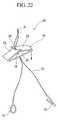
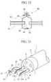
- FIG. 22A suture instrument 85 is equipped with the ring 81 at the first end portion of the suture thread 25. At the second end portion of the suture thread 25, a hook 86 is provided as a second connection member. The hook 86 is thinner than the internal diameter of the ring 81 and the tip portion thereof is folded back so as to be able to be engaged with the ring 81. As shown in FIG. 23, the ring 81 and the hook 86 of the suture instrument 85 are engaged with each other at the abdominal cavity 53 side. By the ring 81 and the hook 86, the end portions of the suture thread 25 are connected with each other to form a loop. By this suture instrument 85, the perforation 52 can be closed in the same manner as with the suture instrument 80 shown in FIG. 21.
- the form of the end portion of the suture thread 25is not limited to a magnet, ring, tag, hook, or the like.
- the end portionsmay be engaged with each other by a treatment tool such as a clip, high-frequency forceps, or the like, followed by tightening up the suture thread 25.
- the suture thread 25may be tightened up after the end portions of the suture thread 25 are adhered to each other by using an adhesive agent.
- the anchors 27 of the first embodimentmay be gripped by a treatment tool to force them to attach to each other, followed by tightening up the suture thread 25.
- the suture units 11may be passed individually through respective channels 9.
- the anchors 27 of the suture instrument 16are individually held in the needle 14 of the respective suture unit 11. The same can be applied to other types of the anchor.
- a perforation formed in a hollow organcan be sutured using a suture thread in accordance with the method including the steps of: causing plural end portions of the suture thread to puncture a tissue around the perforation in the same direction as each other; connecting the end portions of the suture thread to each other; and tightening up the suture thread after connecting the end portions of the suture thread with each other.
- anchors provided at each of the end portions of the suture threadare attached to each other, and the end portions of the suture thread are connected to each other via the anchors.
Landscapes
- Health & Medical Sciences (AREA)
- Life Sciences & Earth Sciences (AREA)
- Surgery (AREA)
- Heart & Thoracic Surgery (AREA)
- Engineering & Computer Science (AREA)
- Biomedical Technology (AREA)
- Nuclear Medicine, Radiotherapy & Molecular Imaging (AREA)
- Medical Informatics (AREA)
- Molecular Biology (AREA)
- Animal Behavior & Ethology (AREA)
- General Health & Medical Sciences (AREA)
- Public Health (AREA)
- Veterinary Medicine (AREA)
- Surgical Instruments (AREA)
- Endoscopes (AREA)
Abstract
Description
- This invention relates to a suture instrument used for suturing. For example, this invention relates to a suture instrument used for suturing a perforation formed in a wall of a hollow organ.
- Priority is claimed on
U.S. Patent Application No. 11/238,006, filed on September 28, 2005 - In the case of performing treatment in a body of a patient, the treatment can be performed by incising the body of the patient by surgical operation, or by oral endoscopic treatment or transanal endoscopic treatment. In the case of using an endoscope, the treatment can be performed by passing through a channel of the endoscope a forceps, high-frequency treatment instrument, incision instrument, suture instrument, or the like. In the case of using an endoscope inserted in the lumen from natural opening of a living body such as, for example, the mouth or anus to perform a medical treatment in the abdominal cavity, tissue is removed from the abdominal cavity or incised to form a hole, and then the medical treatment is carried out by approaching the abdominal cavity from the lumen through this hole. After the end of the medical treatment, the formed hole is sutured by using a suture instrument.
- As a method for suturing a perforation formed in a hollow organ, a suturing method is disclosed in FIGs. 12 to 15 of
United States Patent No. 6290674 . In this suturing method, a catheter for closing the interatrial septum is used. At the tip of the catheter, an anchor supporting member containing an anchor is provided. The anchor supporting member projects through a perforation from the inside to the outside of the tissue. From the anchor supporting member, two anchors are respectively made to perforate the tissue from the outside to the inside thereof. After that, the anchor supporting member is drawn out from the perforation. Since a suture thread is fixed to the anchor, the suture thread penetrates the tissue from the inside to the outside thereof. The suture thread is drawn from the outside into the inside of the tissue through the perforation. When the suture thread is tightened up, the tissue around the perforation is pulled together, and thereby the perforation is closed. - The present invention relates to a suture instrument for suturing a perforation formed in a luminal tissue, characterized by including: a suture thread for penetrating the tissue around the perforation; a first connection member provided at a first end portion of the suture thread; and a second connection member provided at a second end portion of the suture thread and connectable to the first connection member.
- The first connection member may have at least one polarized portion, and the second connection member may have a member which is attached to the first connection member due to a magnetic force of the first connection member.
- The first connection member may have a hole, and the tip of the second connection member may be bent so as to be able to be inserted into the hole.
- FIG 1 is a view showing a schematic constitution of an endoscope and a suture unit.
- FIG 2 is a cross-sectional view of a suture unit and an end portion of an endoscope.
- FIG. 3 is a perspective view of a suture unit and an end portion of an endoscope.
- FIG. 4 is a view showing a constitution of a suture instrument.
- FIG. 5 is a view showing a step of inserting an endoscope into the stomach of a patient to observe a proposed incision position from the inside of the stomach.
- FIG 6 is a view showing a step of inserting an endoscope insertion part from a perforation into the abdominal cavity to carry out treatment.
- FIG 7 is a view showing a step of thrusting a needle to extrude an anchor into an abdominal cavity side.
- FIG 8 is a view indicating the state as viewed from an abdominal cavity side, in which an anchor is placed.
- FIG. 9 is a view in which anchors are made to attach to each other.
- FIG. 10 is a view in which a suture thread of a suture instrument is gripped by a forceps.
- FIG. 11 is a view in which a suture instrument is tightened up by an outer sheath of a forceps.
- FIG 12 is a view showing a suture instrument placed inside of the body.
- FIG 13 is a view indicating the suture instrument of FIG. 12 as viewed from an abdominal cavity side.
- FIG. 14 is a view in which anchors are serially engaged.
- FIG. 15 is a view showing another embodiment of a suture instrument.
- FIG 16 is a view showing another embodiment of a suture instrument.
- FIG 17 is a view showing another embodiment of a suture instrument.
- FIG 18 is a view showing another embodiment of a suture instrument.
- FIG. 19 is a view showing a step of thrusting a needle to extrude an anchor into an abdominal cavity side.
- FIG 20 is a view showing a step of engaging anchors with each other.
- FIG 21 is a view in which anchors are engaged with each other.
- FIG. 22 is a view showing another embodiment of a suture instrument.
- FIG. 23 is a view in which anchors are engaged with each other.
- FIG. 24 is a view in which two suture units are passed through an endoscope.
- In FIG. 1, an endoscope and a suture unit used in this embodiment are shown. An endoscope 1 (flexible endoscope) has an
endoscope operation unit 2 which is operated by an operator. Theendoscope operation unit 2 is connected to a control device via auniversal cable 3 and equipped with various switches 4 andangle knobs 5. At the tip of theendoscope operation unit 2, anendoscope insertion part 6 that is flexible and long is extendedly formed. At the tip of theendoscope insertion part 6, anobservation device 7 for obtaining an image of the internal body, alighting unit 8, and a tip opening of achannel 9 are provided. As theobservation device 7, an imaging device having a CCD (Charge Coupled Device) or an optical fiber can be used. Thelighting unit 8 has an optical fiber that conducts light from a light source. Thechannel 9 opens at alateral part 2a of theendoscope operation unit 2 through theendoscope insertion part 6. At an opening of thelateral part 2a, acap 10 is provided. In thecap 10, an insertion hole is formed, and a treatment instrument such as asuture unit 11 is inserted into thechannel 9 through this insertion hole. - As shown in FIGs. 1 to 3, in the
suture unit 11, a flexibleinner sheath 13 is passed through the inside of a flexibleouter sheath 12 so as to be able to freely move. To the tip of theinner sheath 13, aneedle 14 is fixed. Theneedle 14 has aslit 15 formed in a longitudinal direction from the tip thereof. Asuture instrument 16 is contained inside of theneedle 14. Each of the lengths of theouter sheath 12 and theinner sheath 13 is longer than that of thechannel 9 of theendoscope 1. At a proximal end of theinner sheath 13, anoperation unit 17 is provided. Theoperation unit 17 has ahandle 19 which can freely slide with respect to amain body 18 of the operation unit. To thehandle 19, a proximal end of apusher 20 is fixed. Thepusher 20 extends through the inside of theinner sheath 13 to the inside of theneedle 14. Adistal end portion 21 of thepusher 20 is pressed against thesuture instrument 16. - As shown in FIG. 4, the
suture instrument 16 has asuture thread 25. Thesuture thread 25 is folded approximately in two and aknot 31 is formed in the vicinity of its turn-around point. Moreover, thesuture thread 25 is bundled at both end portions (a first end portion and a second end portion) thereof and passed through astopper 26 that is substantially triangular. To each of the first end portion and the second end portion of thesuture thread 25, ananchor 27 is fixed. Theanchor 27 has a cylindrical shape and thesuture thread 25 is fixed at an approximately center portion in a longitudinal direction of theanchor 27. Both end portions of twoanchors 27 in their longitudinal direction are respectively polarized. Oneend portion 27A of theanchor 27 becomes a south pole of a magnet, and theother end portion 27B becomes a north pole of the magnet. In Fig. 4, theend portion 27A of the south pole and theend portion 27B of the north pole are distinguished by using different colors so as to allow visual distinction. However, theend portions - The
stopper 26 includes a long, thin plate member in which ahole 28 is formed at the center portion in a longitudinal direction thereof, through which thesuture thread 25 is passed. Bothend portions 29 in a longitudinal direction of thestopper 26 are diagonally folded back to hold thesuture thread 25 therebetween. Bothend portions 29 in a longitudinal direction of thestopper 26 are cut to formtriangular sections 30. Bothend portions 29 of thestopper 26 are diagonally folded back so that thesections 30 intersect with each other to hold thesuture thread 25 therebetween. As a result, thesuture thread 25 is prevented from passing through a space formed betweenend portions 29. When theknot 31 of thesuture thread 25 is pulled in a direction away from thestopper 26, bothend portions 29 of thestopper 26 are slightly opened. Accordingly, thestopper 26 allows thesuture thread 26 to move in the same direction. On the other hand, when end portions of thesuture thread 25 at the side of theanchors 27 are pulled, thesuture thread 25 is ready to move in a direction shown by an arrow in FIG. 4. At this time, however, thesuture thread 25 does not move, since bothend portions 29 of thestopper 26 are closed and secure thesuture thread 25. - As shown in FIG. 3, the
suture instrument 16 sequentially holds twoanchors 27 in an inner hole of theneedle 14. Thesuture thread 25 is drawn out from theslit 15 of theneedle 14. As shown in FIG. 2, thestopper 26 is held at a more distal end portion than theneedle 14 in theouter sheath 12. The number of theanchors 27 and the shape of thestopper 26 are not limited to the embodiment shown in the figures. - Next, a suturing method of this embodiment will be explained mainly with reference to FIGs. 5 to 14. FIGs. 5 to 12 are pattern diagrams illustrating manipulation and show the stomach as an example of a hollow organ.
- As shown in FIG. 5, the
endoscope insertion part 6 is inserted from the mouth (a natural opening of a living body, such as the anus, nose, or ear) of a patient 41 prepared with amouthpiece 40. The tip of theendoscope insertion part 6 is bent by theangle knob 5. A needle-like knife that is a high-frequency incision tool is passed through thechannel 9 of theendoscope insertion part 6, and a perforation is formed by incising the tissue of the wall of thestomach 43. As shown in FIG. 6, theendoscope insertion part 6 is directed to theabdominal cavity 53 through theperforation 52 formed in thestomach 43. Aforceps 54 is passed through thechannel 9, and the treatment in theabdominal cavity 53 is carried out by using theforceps 54. After finishing the treatment, theendoscope insertion part 6 is drawn back to the inside of thestomach 43. - When the
perforation 52 is sutured, thesuture unit 11 is passed through thechannel 9 of theendoscope insertion part 6, and theneedle 14 of thesuture unit 11 is projected from theouter sheath 12. At this time, thestopper 26 falls to thestomach 43. When thesuture unit 11 is moved forward, theneedle 14 is thrust into the tissue around the perforation 52 (inside of the stomach 43). When the tip portion of theneedle 14 penetrates the tissue and projects to theabdominal cavity 53 side, the forward movement of thesuture unit 11 is stopped. The handle 19 (see FIG 1) of theoperation unit 17 is manipulated to move thepusher 20 forward. As shown in FIG 7, the first anchor 27 (the first connection member) is pushed out to theabdominal cavity 53. When theneedle 14 is pulled out from the tissue, theanchor 27 is placed in theabdominal cavity 53. Thesuture thread 25 penetrates the tissue in the wall of thestomach 43. Next, theneedle 14 is thrust again in the same direction (direction toward theabdominal cavity 43 from the inside of the stomach 43) at an approximately symmetrical position across theperforation 52 with respect to the position at which theneedle 14 is thrust to place thefirst anchor 27. When the tip of theneedle 14 penetrates the tissue and projects to theabdominal cavity 53 side, the second anchor 27 (the second connection member) is pushed out. As shown in FIG. 8, the second anchor 27 (the second connection member) is placed at an approximately symmetrical position across theperforation 52 with respect to the position at which thefirst anchor 27 is placed. - Since the two
anchors 27 have theend portions end portion 27A of thefirst anchor 27 and theother end portion 27B of thesecond anchor 27 attract each other. In the same way, oneend portion 27B of thefirst anchor 27 and theother end portion 27A of thesecond anchor 27 attract each other. Accordingly, as shown in FIG. 9, the twoanchors 27 attach to each other before closing theperforation 52. Since the thrust positions are near, the twoanchors 27 adhere parallel to each other. By attachment of the twoanchors 27, both end portions of thesuture thread 25 are connected via theseanchors 27. - After the
suture instrument 16 is mounted on the wall so as to cross theperforation 52, thesuture instrument 16 is tightened up. In order to tighten up thesuture instrument 16, aforceps 62 shown in FIG. 10, for example, is used. Theforceps 60 includes anouter sheath 61 having an external diameter larger than theanchor 27 and aninner sheath 62 passing through the inside of theouter sheath 61 so as to be able to freely move forward or backward. At the tip of theinner sheath 62, a supportingmember 63 is provided, and a pair ofgrip segments 64 are supported on the supportingmember 63 so as to be able to freely open or close. - After the
knot 31 of thesuture thread 25 of thesuture instrument 16 is gripped by thegrip segments 64, theouter sheath 61 is moved forward to press the tip of theouter sheath 61 against thestopper 26. As shown in FIG 11, when theouter sheath 61 is moved further forward, thestopper 26 is pushed into the wall of thestomach 43. Since thestopper 26 is constructed to be able to move in this direction, thestopper 26 moves toward the wall. Since the position of the pair of thegrip segments 64 does not change, thestopper 26 moves relatively forward with respect to thesuture thread 25. As a result, the distance between thestopper 26 and theanchor 27 decreases, and thesuture thread 25 is gathered. This pulls together the tissue around theperforation 52 as shown in FIGs. 12 and 13, and theperforation 52 is sutured by thesuture thread 25. - After the
perforation 52 is sutured by thesuture instrument 16, theouter sheath 61 is moved backward, and then thegrip segments 64 are opened to release thesuture thread 25. Although the tip of thestopper 26 can move in a direction in which the tissue is tightened up by thesuture thread 25, it acts to tighten up thesuture thread 25 in a direction for loosening thesuture thread 25. As a result, thesuture thread 25 is not loosened, even if thesuture instrument 16 is placed inside of thestomach 43. - As shown in FIG 12, when the two
anchors 27 attach parallel to each other, the tissue around theperforation 52 is collapsed, and the diameter of a loop of thesuture thread 25 decreases. On the contrary, as shown in FIG. 14, when oneend portion 27A of thefirst anchor 27 and theother end portion 27B of thesecond anchor 27 serially and attach to each other, the distance between thesuture thread 25 penetrating the tissue increases. The diameter of the loop of thesuture thread 25 formed via theanchor 27 increases. - In this embodiment, since a pair of the
anchors 27 of thesuture instrument 16 are polarized so as to pull together, theanchors 27 approach each other, and attach to each other when suturing theperforation 52. Since anchors of a suture instrument of the prior art are completely independent and attitude or position thereof cannot be controlled, the tissue around the perforation is unevenly pulled and tends to leave a gap. According to this embodiment, since theanchors 27 attach to each other, the unevenness of the tissue is prevented and the tissue around the perforation formed in thestomach 43 can close neatly. Thus, theperforation 52 is properly closed. When theanchors 27 attach parallel to each other, the attached area is large, and thereby a high engagement strength can be achieved. Moreover, since theanchors 27 are parallel to a line of closure formed due to the close contact with the inner edges of theperforation 52, theperforation 52 can be more properly closed. - Since the
suture thread 25 forms a closed loop via theanchors 27 that attach to each other due to a magnetic force, it is possible to bring the inside and the outside of both sides of the tissue across theperforation 52 closely. Accordingly, as in the case of surgical suturing, suturing can be properly carried out. The diameter of the loop of thesuture thread 25 can be controlled in accordance with a way of attaching theanchors 27. When the diameter of the loop is desired to be enlarged, theanchors 27 may be attached parallel to each other. When the diameter of the loop of thesuture thread 25 is desired to be diminished, theanchors 27 may be closely and linearly attached to each other. - Another aspect of the
anchor 27 is shown in FIGs. 15 to 17. Anchors 70 as shown in FIG. 15 are connection members respectively provided at the first and the second end portions of thesuture thread 25 and divided in two perpendicularly in a longitudinal direction. Oneportion 70A of the connection member divided in two becomes a south pole and theother portion 70B becomes a north pole. Since the attached area due to a magnetic force is large, it becomes easy for the anchors to attach to each other.- The
anchors 71 as shown in FIG. 16 are connection members respectively provided at the first and the second end portions of thesuture thread 25 and divided in two parallel to a longitudinal direction. Oneportion 71 A of the connection member divided in two becomes a south pole and theother portion 71 B becomes a north pole. - As shown in FIG. 17, a
first anchor 72 is a first connection member provided at the first end portion of thesuture thread 25 and produced from a magnet. Asecond anchor 73 is a second connection member provided at the second end portion of thesuture thread 25 and produced from a ferromagnet. As the ferromagnet, pure iron, Permalloy, or the like is used. Theanchor 73 attaches to theanchor 72 due to the magnetic force of theanchor 72, and both end portions of thesuture thread 25 are connected via theseanchors anchor 72 is a magnet, the same effect as described above can be achieved. - These
anchors - In this embodiment, the
same endoscope 1 andsuture unit 11 as in the first embodiment are used. Descriptions that overlap with the first embodiment will be omitted. - As shown in FIG 18, a
suture instrument 80 is equipped with aring 81 at the first end portion of thesuture thread 25. Thering 81 is a first connection member having a hole. At the second end portion of thesuture thread 25, atag 82 that is a second connection member is provided. The thickness of thetag 82 is of a size which allows it to be inserted into the inside of thering 81. The length of thetag 82 is larger than the external diameter of thering 81. Thering 81 and thetag 82 can be contained inside of theneedle 14. For this reason, thering 81 and thetag 82 are made from a material having flexibility and are held in theneedle 14 in a folded form. Thering 81 and thetag 82 may be produced so as to be in a size smaller than the inner diameter of theneedle 14. - A suturing method of this embodiment will be explained.
- As shown in FIG. 5, the
endoscope 1 is directed to thestomach 43. As shown in FIG. 6, theendoscope insertion part 6 enters theabdominal cavity 53 through theperforation 52. By using theforceps 54 passed through theendoscope insertion part 6, the treatment is carried out in theabdominal cavity 53. When theperforation 52 is sutured, thesuture unit 11 is used. As shown in FIG. 19, after theneedle 14 of thesuture unit 11 penetrates the tissue around theperforation 52 from the inside of thestomach 43 toward theabdominal cavity 53, thepusher 20 is moved forward, and thering 81 is pushed out from theneedle 14. When thering 82 is pushed out, theneedle 14 is drawn back to be pulled out from the tissue. Moreover, theneedle 14 penetrates at an approximately symmetrical position across theperforation 52 in the same direction as for placing thering 81, that is, from the inside of thestomach 43 toward theabdominal cavity 53. Thepusher 20 is moved further forward. From theneedle 14, thetag 82 is pushed out to theabdominal cavity 53 side. When thetag 82 is pushed out, theneedle 14 is pulled out from the wall. - As shown in FIG. 20, the
forceps 54 is passed through thechannel 9 of theendoscope 1. Theforceps 54 is directed through theperforation 52 to theabdominal cavity 53, and grips thetag 82 in theabdominal cavity 53. Thistag 82 is inserted inside of thering 81. As shown in FIG. 21, thering 81 is engaged with thetag 82, and both end portions of thesuture thread 25 are connected to each other via thering 81 and thetag 82. - After the
forceps 54 is pulled back from theperforation 52 to thestomach 43, thesuture instrument 80 is tightened up. The tightening method is the same as in the first embodiment. A loop of thesuture thread 25 is formed to close theperforation 52. - According to this embodiment, since the
ring 81 and thetag 82 are respectively provided at the end portion of thesuture thread 25, the loop of thesuture thread 25 can be properly formed by engaging thering 81 with thetag 82, and thereby the perforation can be properly sutured. - Next, another embodiment of the suture instrument is shown in FIG. 22. A
suture instrument 85 is equipped with thering 81 at the first end portion of thesuture thread 25. At the second end portion of thesuture thread 25, ahook 86 is provided as a second connection member. Thehook 86 is thinner than the internal diameter of thering 81 and the tip portion thereof is folded back so as to be able to be engaged with thering 81. As shown in FIG. 23, thering 81 and thehook 86 of thesuture instrument 85 are engaged with each other at theabdominal cavity 53 side. By thering 81 and thehook 86, the end portions of thesuture thread 25 are connected with each other to form a loop. By thissuture instrument 85, theperforation 52 can be closed in the same manner as with thesuture instrument 80 shown in FIG. 21. - Moreover, this invention can be widely applied without being limited to the above-mentioned embodiments.
- The form of the end portion of the
suture thread 25 is not limited to a magnet, ring, tag, hook, or the like. After bundling the end portions of thesuture thread 25, the end portions may be engaged with each other by a treatment tool such as a clip, high-frequency forceps, or the like, followed by tightening up thesuture thread 25. Thesuture thread 25 may be tightened up after the end portions of thesuture thread 25 are adhered to each other by using an adhesive agent. - The
anchors 27 of the first embodiment may be gripped by a treatment tool to force them to attach to each other, followed by tightening up thesuture thread 25. - As shown in FIG. 24, when the
endoscope insertion part 6 has twochannels 9, thesuture units 11 may be passed individually throughrespective channels 9. In this case, theanchors 27 of thesuture instrument 16 are individually held in theneedle 14 of therespective suture unit 11. The same can be applied to other types of the anchor. - According to the present invention, a perforation formed in a hollow organ can be sutured using a suture thread in accordance with the method including the steps of: causing plural end portions of the suture thread to puncture a tissue around the perforation in the same direction as each other; connecting the end portions of the suture thread to each other; and tightening up the suture thread after connecting the end portions of the suture thread with each other. In the step of connecting the end portions of the suture thread to each other, anchors provided at each of the end portions of the suture thread are attached to each other, and the end portions of the suture thread are connected to each other via the anchors.
Claims (3)
- A suture instrument for suturing a perforation formed in a luminal tissue,characterized by comprising:a suture thread for penetrating the tissue around the perforation;a first connection member provided at a first end portion of the suture thread; anda second connection member provided at a second end portion of the suture thread and connectable to the first connection member.
- The suture instrument according to claim 1,characterized in that the first connection member has at least one polarized portion, and the second connection member has a member which is attached to the first connection member due to a magnetic force of the first connection member.
- The suture instrument according to claim 1,characterized in that the first connection member has a hole, and the tip of the second connection member is bent so as to be able to be inserted into the hole.
Applications Claiming Priority (1)
| Application Number | Priority Date | Filing Date | Title |
|---|---|---|---|
| US11/238,006US8702753B2 (en) | 2005-09-28 | 2005-09-28 | Method for suturing perforation and suture instrument |
Publications (2)
| Publication Number | Publication Date |
|---|---|
| EP1769749A1true EP1769749A1 (en) | 2007-04-04 |
| EP1769749B1 EP1769749B1 (en) | 2009-11-04 |
Family
ID=37561341
Family Applications (1)
| Application Number | Title | Priority Date | Filing Date |
|---|---|---|---|
| EP06020026ANot-in-forceEP1769749B1 (en) | 2005-09-28 | 2006-09-25 | Surgical suture instrument |
Country Status (4)
| Country | Link |
|---|---|
| US (1) | US8702753B2 (en) |
| EP (1) | EP1769749B1 (en) |
| JP (1) | JP4790549B2 (en) |
| DE (1) | DE602006010153D1 (en) |
Cited By (13)
| Publication number | Priority date | Publication date | Assignee | Title |
|---|---|---|---|---|
| WO2009158246A1 (en)* | 2008-06-27 | 2009-12-30 | Ethicon Endo-Surgery, Inc. | Surgical suture arrangement |
| WO2011025767A1 (en)* | 2009-08-24 | 2011-03-03 | Smith & Nephew, Inc. | Magnetic suture or instrument |
| WO2011156591A3 (en)* | 2010-06-09 | 2012-02-02 | C.R. Bard, Inc. | Instruments for delivering transfascial sutures, transfascial suture assemblies, and methods of transfascial suturing |
| WO2013004264A1 (en)* | 2011-07-01 | 2013-01-10 | Ethicon Endo-Surgery, Inc. | A method and device for creating an alternative bile flow path |
| EP2260752A3 (en)* | 2006-08-28 | 2013-05-15 | Olympus Medical Systems Corporation | Ultrasonic endoscope, catheter with balloon, magnet indwelling device, and magnet set |
| WO2014055193A1 (en)* | 2012-09-07 | 2014-04-10 | Ethicon Endo-Surgery, Inc. | Magnetic compression anastomosis device |
| US9039721B2 (en) | 2011-11-07 | 2015-05-26 | C.R. Bard, Inc. | Instruments for delivering transfascial sutures and methods of transfascial suturing |
| US9078648B2 (en) | 2011-11-07 | 2015-07-14 | C.R. Bard, Inc. | Instruments for delivering transfascial sutures and methods of transfascial suturing |
| WO2016054387A1 (en)* | 2014-10-01 | 2016-04-07 | Boston Scientific Scimed, Inc. | Magnetic and/or hook and loop t-tags |
| US9826972B2 (en) | 2011-10-24 | 2017-11-28 | C.R. Bard, Inc. | Instruments for delivering transfascial sutures, transfascial suture assemblies and methods of transfascial suturing |
| US9924938B2 (en) | 2011-11-07 | 2018-03-27 | C.R. Bard, Inc. | Instruments for delivering transfascial sutures and methods of transfascial suturing |
| US10342598B2 (en) | 2012-08-15 | 2019-07-09 | Ethicon Llc | Electrosurgical system for delivering a biphasic waveform |
| WO2019231813A1 (en)* | 2018-05-29 | 2019-12-05 | Edwards Lifesciences Corporation | Pledgeted tissue anchor |
Families Citing this family (126)
| Publication number | Priority date | Publication date | Assignee | Title |
|---|---|---|---|---|
| ES2435094T3 (en) | 2000-05-19 | 2013-12-18 | C.R. Bard, Inc. | Device and method of tissue capture and suturing |
| CN1822794B (en) | 2003-05-16 | 2010-05-26 | C.R.巴德有限公司 | Single cannula, multiple needle endoscopic suturing system |
| US7749250B2 (en) | 2006-02-03 | 2010-07-06 | Biomet Sports Medicine, Llc | Soft tissue repair assembly and associated method |
| US7905904B2 (en) | 2006-02-03 | 2011-03-15 | Biomet Sports Medicine, Llc | Soft tissue repair device and associated methods |
| US8361113B2 (en) | 2006-02-03 | 2013-01-29 | Biomet Sports Medicine, Llc | Method and apparatus for coupling soft tissue to a bone |
| US8088130B2 (en) | 2006-02-03 | 2012-01-03 | Biomet Sports Medicine, Llc | Method and apparatus for coupling soft tissue to a bone |
| US8137382B2 (en) | 2004-11-05 | 2012-03-20 | Biomet Sports Medicine, Llc | Method and apparatus for coupling anatomical features |
| US8303604B2 (en) | 2004-11-05 | 2012-11-06 | Biomet Sports Medicine, Llc | Soft tissue repair device and method |
| US8118836B2 (en) | 2004-11-05 | 2012-02-21 | Biomet Sports Medicine, Llc | Method and apparatus for coupling soft tissue to a bone |
| US8128658B2 (en) | 2004-11-05 | 2012-03-06 | Biomet Sports Medicine, Llc | Method and apparatus for coupling soft tissue to bone |
| US9801708B2 (en) | 2004-11-05 | 2017-10-31 | Biomet Sports Medicine, Llc | Method and apparatus for coupling soft tissue to a bone |
| US7909851B2 (en) | 2006-02-03 | 2011-03-22 | Biomet Sports Medicine, Llc | Soft tissue repair device and associated methods |
| US9017381B2 (en) | 2007-04-10 | 2015-04-28 | Biomet Sports Medicine, Llc | Adjustable knotless loops |
| US8298262B2 (en) | 2006-02-03 | 2012-10-30 | Biomet Sports Medicine, Llc | Method for tissue fixation |
| US7658751B2 (en) | 2006-09-29 | 2010-02-09 | Biomet Sports Medicine, Llc | Method for implanting soft tissue |
| US9078644B2 (en) | 2006-09-29 | 2015-07-14 | Biomet Sports Medicine, Llc | Fracture fixation device |
| US9271713B2 (en) | 2006-02-03 | 2016-03-01 | Biomet Sports Medicine, Llc | Method and apparatus for tensioning a suture |
| US9468433B2 (en) | 2006-02-03 | 2016-10-18 | Biomet Sports Medicine, Llc | Method and apparatus for forming a self-locking adjustable loop |
| US8562645B2 (en) | 2006-09-29 | 2013-10-22 | Biomet Sports Medicine, Llc | Method and apparatus for forming a self-locking adjustable loop |
| US8597327B2 (en) | 2006-02-03 | 2013-12-03 | Biomet Manufacturing, Llc | Method and apparatus for sternal closure |
| US11259792B2 (en) | 2006-02-03 | 2022-03-01 | Biomet Sports Medicine, Llc | Method and apparatus for coupling anatomical features |
| US10517587B2 (en) | 2006-02-03 | 2019-12-31 | Biomet Sports Medicine, Llc | Method and apparatus for forming a self-locking adjustable loop |
| US8968364B2 (en) | 2006-02-03 | 2015-03-03 | Biomet Sports Medicine, Llc | Method and apparatus for fixation of an ACL graft |
| US8801783B2 (en) | 2006-09-29 | 2014-08-12 | Biomet Sports Medicine, Llc | Prosthetic ligament system for knee joint |
| US8506597B2 (en) | 2011-10-25 | 2013-08-13 | Biomet Sports Medicine, Llc | Method and apparatus for interosseous membrane reconstruction |
| US8771352B2 (en) | 2011-05-17 | 2014-07-08 | Biomet Sports Medicine, Llc | Method and apparatus for tibial fixation of an ACL graft |
| US8562647B2 (en) | 2006-09-29 | 2013-10-22 | Biomet Sports Medicine, Llc | Method and apparatus for securing soft tissue to bone |
| US9408599B2 (en) | 2006-02-03 | 2016-08-09 | Biomet Sports Medicine, Llc | Method and apparatus for coupling soft tissue to a bone |
| US9538998B2 (en) | 2006-02-03 | 2017-01-10 | Biomet Sports Medicine, Llc | Method and apparatus for fracture fixation |
| US8652171B2 (en) | 2006-02-03 | 2014-02-18 | Biomet Sports Medicine, Llc | Method and apparatus for soft tissue fixation |
| US8652172B2 (en) | 2006-02-03 | 2014-02-18 | Biomet Sports Medicine, Llc | Flexible anchors for tissue fixation |
| US9149267B2 (en) | 2006-02-03 | 2015-10-06 | Biomet Sports Medicine, Llc | Method and apparatus for coupling soft tissue to a bone |
| US11311287B2 (en) | 2006-02-03 | 2022-04-26 | Biomet Sports Medicine, Llc | Method for tissue fixation |
| US8500818B2 (en) | 2006-09-29 | 2013-08-06 | Biomet Manufacturing, Llc | Knee prosthesis assembly with ligament link |
| US11259794B2 (en) | 2006-09-29 | 2022-03-01 | Biomet Sports Medicine, Llc | Method for implanting soft tissue |
| US8672969B2 (en) | 2006-09-29 | 2014-03-18 | Biomet Sports Medicine, Llc | Fracture fixation device |
| US9918826B2 (en) | 2006-09-29 | 2018-03-20 | Biomet Sports Medicine, Llc | Scaffold for spring ligament repair |
| US7655004B2 (en) | 2007-02-15 | 2010-02-02 | Ethicon Endo-Surgery, Inc. | Electroporation ablation apparatus, system, and method |
| US7815662B2 (en) | 2007-03-08 | 2010-10-19 | Ethicon Endo-Surgery, Inc. | Surgical suture anchors and deployment device |
| US8075572B2 (en) | 2007-04-26 | 2011-12-13 | Ethicon Endo-Surgery, Inc. | Surgical suturing apparatus |
| US8100922B2 (en) | 2007-04-27 | 2012-01-24 | Ethicon Endo-Surgery, Inc. | Curved needle suturing tool |
| US8579897B2 (en) | 2007-11-21 | 2013-11-12 | Ethicon Endo-Surgery, Inc. | Bipolar forceps |
| US8568410B2 (en) | 2007-08-31 | 2013-10-29 | Ethicon Endo-Surgery, Inc. | Electrical ablation surgical instruments |
| US8262655B2 (en) | 2007-11-21 | 2012-09-11 | Ethicon Endo-Surgery, Inc. | Bipolar forceps |
| US20090112059A1 (en) | 2007-10-31 | 2009-04-30 | Nobis Rudolph H | Apparatus and methods for closing a gastrotomy |
| US8480657B2 (en) | 2007-10-31 | 2013-07-09 | Ethicon Endo-Surgery, Inc. | Detachable distal overtube section and methods for forming a sealable opening in the wall of an organ |
| EP2098172B1 (en) | 2008-03-04 | 2017-02-22 | Arthrex, Inc. | System for meniscal repair using suture implant cinch construct |
| US8262680B2 (en) | 2008-03-10 | 2012-09-11 | Ethicon Endo-Surgery, Inc. | Anastomotic device |
| US20090259232A1 (en)* | 2008-04-11 | 2009-10-15 | Junji Shiono | Suture device |
| US8771260B2 (en) | 2008-05-30 | 2014-07-08 | Ethicon Endo-Surgery, Inc. | Actuating and articulating surgical device |
| US8114072B2 (en) | 2008-05-30 | 2012-02-14 | Ethicon Endo-Surgery, Inc. | Electrical ablation device |
| US8317806B2 (en) | 2008-05-30 | 2012-11-27 | Ethicon Endo-Surgery, Inc. | Endoscopic suturing tension controlling and indication devices |
| US8070759B2 (en) | 2008-05-30 | 2011-12-06 | Ethicon Endo-Surgery, Inc. | Surgical fastening device |
| US8679003B2 (en) | 2008-05-30 | 2014-03-25 | Ethicon Endo-Surgery, Inc. | Surgical device and endoscope including same |
| US8652150B2 (en) | 2008-05-30 | 2014-02-18 | Ethicon Endo-Surgery, Inc. | Multifunction surgical device |
| US8906035B2 (en) | 2008-06-04 | 2014-12-09 | Ethicon Endo-Surgery, Inc. | Endoscopic drop off bag |
| US8403926B2 (en) | 2008-06-05 | 2013-03-26 | Ethicon Endo-Surgery, Inc. | Manually articulating devices |
| CN102088915A (en)* | 2008-06-06 | 2011-06-08 | 斯恩蒂斯有限公司 | Suture based tissue repair |
| US8888792B2 (en) | 2008-07-14 | 2014-11-18 | Ethicon Endo-Surgery, Inc. | Tissue apposition clip application devices and methods |
| US8262563B2 (en) | 2008-07-14 | 2012-09-11 | Ethicon Endo-Surgery, Inc. | Endoscopic translumenal articulatable steerable overtube |
| US8231640B2 (en) | 2008-07-31 | 2012-07-31 | Olympus Medical Systems Corp. | Suture instrument |
| US8211125B2 (en) | 2008-08-15 | 2012-07-03 | Ethicon Endo-Surgery, Inc. | Sterile appliance delivery device for endoscopic procedures |
| US12419632B2 (en) | 2008-08-22 | 2025-09-23 | Biomet Sports Medicine, Llc | Method and apparatus for coupling anatomical features |
| US12245759B2 (en) | 2008-08-22 | 2025-03-11 | Biomet Sports Medicine, Llc | Method and apparatus for coupling soft tissue to bone |
| US8529563B2 (en) | 2008-08-25 | 2013-09-10 | Ethicon Endo-Surgery, Inc. | Electrical ablation devices |
| US8241204B2 (en) | 2008-08-29 | 2012-08-14 | Ethicon Endo-Surgery, Inc. | Articulating end cap |
| US8480689B2 (en) | 2008-09-02 | 2013-07-09 | Ethicon Endo-Surgery, Inc. | Suturing device |
| US8409200B2 (en) | 2008-09-03 | 2013-04-02 | Ethicon Endo-Surgery, Inc. | Surgical grasping device |
| US8114119B2 (en) | 2008-09-09 | 2012-02-14 | Ethicon Endo-Surgery, Inc. | Surgical grasping device |
| US8337394B2 (en) | 2008-10-01 | 2012-12-25 | Ethicon Endo-Surgery, Inc. | Overtube with expandable tip |
| WO2010042402A1 (en)* | 2008-10-06 | 2010-04-15 | Wilson-Cook Medical, Inc. | Endcap for safely deploying tissue anchors |
| US8157834B2 (en) | 2008-11-25 | 2012-04-17 | Ethicon Endo-Surgery, Inc. | Rotational coupling device for surgical instrument with flexible actuators |
| US8172772B2 (en) | 2008-12-11 | 2012-05-08 | Ethicon Endo-Surgery, Inc. | Specimen retrieval device |
| US8828031B2 (en) | 2009-01-12 | 2014-09-09 | Ethicon Endo-Surgery, Inc. | Apparatus for forming an anastomosis |
| US8361066B2 (en) | 2009-01-12 | 2013-01-29 | Ethicon Endo-Surgery, Inc. | Electrical ablation devices |
| US8252057B2 (en) | 2009-01-30 | 2012-08-28 | Ethicon Endo-Surgery, Inc. | Surgical access device |
| US9226772B2 (en) | 2009-01-30 | 2016-01-05 | Ethicon Endo-Surgery, Inc. | Surgical device |
| US8037591B2 (en) | 2009-02-02 | 2011-10-18 | Ethicon Endo-Surgery, Inc. | Surgical scissors |
| US8343227B2 (en) | 2009-05-28 | 2013-01-01 | Biomet Manufacturing Corp. | Knee prosthesis assembly with ligament link |
| US12096928B2 (en) | 2009-05-29 | 2024-09-24 | Biomet Sports Medicine, Llc | Method and apparatus for coupling soft tissue to a bone |
| US20110098704A1 (en) | 2009-10-28 | 2011-04-28 | Ethicon Endo-Surgery, Inc. | Electrical ablation devices |
| US8608652B2 (en) | 2009-11-05 | 2013-12-17 | Ethicon Endo-Surgery, Inc. | Vaginal entry surgical devices, kit, system, and method |
| US8496574B2 (en) | 2009-12-17 | 2013-07-30 | Ethicon Endo-Surgery, Inc. | Selectively positionable camera for surgical guide tube assembly |
| US8353487B2 (en) | 2009-12-17 | 2013-01-15 | Ethicon Endo-Surgery, Inc. | User interface support devices for endoscopic surgical instruments |
| US8506564B2 (en) | 2009-12-18 | 2013-08-13 | Ethicon Endo-Surgery, Inc. | Surgical instrument comprising an electrode |
| US9028483B2 (en) | 2009-12-18 | 2015-05-12 | Ethicon Endo-Surgery, Inc. | Surgical instrument comprising an electrode |
| US9005198B2 (en) | 2010-01-29 | 2015-04-14 | Ethicon Endo-Surgery, Inc. | Surgical instrument comprising an electrode |
| US10092291B2 (en) | 2011-01-25 | 2018-10-09 | Ethicon Endo-Surgery, Inc. | Surgical instrument with selectively rigidizable features |
| US9233241B2 (en) | 2011-02-28 | 2016-01-12 | Ethicon Endo-Surgery, Inc. | Electrical ablation devices and methods |
| US9254169B2 (en) | 2011-02-28 | 2016-02-09 | Ethicon Endo-Surgery, Inc. | Electrical ablation devices and methods |
| US9314620B2 (en) | 2011-02-28 | 2016-04-19 | Ethicon Endo-Surgery, Inc. | Electrical ablation devices and methods |
| KR101132841B1 (en) | 2011-03-07 | 2012-04-02 | 김영재 | A suture |
| US9049987B2 (en) | 2011-03-17 | 2015-06-09 | Ethicon Endo-Surgery, Inc. | Hand held surgical device for manipulating an internal magnet assembly within a patient |
| US12329373B2 (en) | 2011-05-02 | 2025-06-17 | Biomet Sports Medicine, Llc | Method and apparatus for soft tissue fixation |
| US9357991B2 (en) | 2011-11-03 | 2016-06-07 | Biomet Sports Medicine, Llc | Method and apparatus for stitching tendons |
| US9370350B2 (en) | 2011-11-10 | 2016-06-21 | Biomet Sports Medicine, Llc | Apparatus for coupling soft tissue to a bone |
| US9381013B2 (en) | 2011-11-10 | 2016-07-05 | Biomet Sports Medicine, Llc | Method for coupling soft tissue to a bone |
| US9314241B2 (en) | 2011-11-10 | 2016-04-19 | Biomet Sports Medicine, Llc | Apparatus for coupling soft tissue to a bone |
| KR101185583B1 (en) | 2011-12-27 | 2012-09-24 | 김영재 | A suture which need not be knotted and a kit comprising the suture |
| US8986199B2 (en) | 2012-02-17 | 2015-03-24 | Ethicon Endo-Surgery, Inc. | Apparatus and methods for cleaning the lens of an endoscope |
| US9427255B2 (en) | 2012-05-14 | 2016-08-30 | Ethicon Endo-Surgery, Inc. | Apparatus for introducing a steerable camera assembly into a patient |
| US9078662B2 (en) | 2012-07-03 | 2015-07-14 | Ethicon Endo-Surgery, Inc. | Endoscopic cap electrode and method for using the same |
| US9545290B2 (en) | 2012-07-30 | 2017-01-17 | Ethicon Endo-Surgery, Inc. | Needle probe guide |
| US9572623B2 (en) | 2012-08-02 | 2017-02-21 | Ethicon Endo-Surgery, Inc. | Reusable electrode and disposable sheath |
| US10314649B2 (en) | 2012-08-02 | 2019-06-11 | Ethicon Endo-Surgery, Inc. | Flexible expandable electrode and method of intraluminal delivery of pulsed power |
| US10178990B2 (en) | 2012-12-05 | 2019-01-15 | Y. Jacobs Medical Inc. | Apparatus for inserting surgical thread, and surgical procedure kit for inserting surgical thread comprising same |
| US10010317B2 (en) | 2012-12-05 | 2018-07-03 | Young Jae Kim | Method of improving elasticity of tissue of living body |
| US10098527B2 (en) | 2013-02-27 | 2018-10-16 | Ethidcon Endo-Surgery, Inc. | System for performing a minimally invasive surgical procedure |
| US9757119B2 (en) | 2013-03-08 | 2017-09-12 | Biomet Sports Medicine, Llc | Visual aid for identifying suture limbs arthroscopically |
| US9918827B2 (en) | 2013-03-14 | 2018-03-20 | Biomet Sports Medicine, Llc | Scaffold for spring ligament repair |
| US10245021B2 (en)* | 2013-10-08 | 2019-04-02 | Applied Medical Technology, Inc | Magnetic U-stitch device |
| WO2015083864A1 (en) | 2013-12-06 | 2015-06-11 | 주식회사 와이제이콥스메디칼 | Apparatus for inserting medical tube and surgical procedure kit for inserting medical tube, having same |
| US10136886B2 (en) | 2013-12-20 | 2018-11-27 | Biomet Sports Medicine, Llc | Knotless soft tissue devices and techniques |
| US9615822B2 (en) | 2014-05-30 | 2017-04-11 | Biomet Sports Medicine, Llc | Insertion tools and method for soft anchor |
| US9700291B2 (en) | 2014-06-03 | 2017-07-11 | Biomet Sports Medicine, Llc | Capsule retractor |
| US10039543B2 (en) | 2014-08-22 | 2018-08-07 | Biomet Sports Medicine, Llc | Non-sliding soft anchor |
| US9955980B2 (en) | 2015-02-24 | 2018-05-01 | Biomet Sports Medicine, Llc | Anatomic soft tissue repair |
| US9974534B2 (en) | 2015-03-31 | 2018-05-22 | Biomet Sports Medicine, Llc | Suture anchor with soft anchor of electrospun fibers |
| WO2018087769A1 (en) | 2016-11-13 | 2018-05-17 | Anchora Medical Ltd. | Minimally-invasive tissue suturing device |
| US10675015B2 (en) | 2017-07-12 | 2020-06-09 | Ethicon, Inc. | Systems, devices and methods for delivering transfascial suture implants for securing surgical mesh to tissue |
| EP3993710A1 (en)* | 2019-07-03 | 2022-05-11 | Ergosurgical Group Corp. | Threading devices and methods of manufacture thereof |
| US11375994B2 (en)* | 2019-07-12 | 2022-07-05 | Abbot Cardiovascular Systems, Inc. | Methods, systems, and devices for positioning sutures for closing an opening in tissue |
| US11969166B2 (en)* | 2020-10-07 | 2024-04-30 | Smith & Nephew, Inc. | Hip capsule closure |
| USD977639S1 (en)* | 2020-11-20 | 2023-02-07 | Palliare Limited | Suture |
| WO2022245822A1 (en) | 2021-05-17 | 2022-11-24 | Applied Medical Technology, Inc. | Magnet-assisted suture graspers |
| CN114631861A (en)* | 2022-02-15 | 2022-06-17 | 范宁 | Pipeline anastomosis wire lifting device for surgical operation |
Citations (5)
| Publication number | Priority date | Publication date | Assignee | Title |
|---|---|---|---|---|
| US4950285A (en)* | 1989-11-27 | 1990-08-21 | Wilk Peter J | Suture device |
| CA2306528A1 (en)* | 1995-06-06 | 1996-12-12 | Raymond Thal | Knotless suture anchor assembly |
| US6290674B1 (en)* | 1999-09-20 | 2001-09-18 | Appriva Medical, Inc. | Method and apparatus for closing intracardiac septal defects |
| US20030105474A1 (en)* | 2001-12-03 | 2003-06-05 | Bonutti Peter M. | Magnetic suturing system and method |
| EP1484023A1 (en)* | 2003-06-06 | 2004-12-08 | Olympus Corporation | Anastomosing instrument |
Family Cites Families (20)
| Publication number | Priority date | Publication date | Assignee | Title |
|---|---|---|---|---|
| US3875648A (en)* | 1973-04-04 | 1975-04-08 | Dennison Mfg Co | Fastener attachment apparatus and method |
| US4006747A (en)* | 1975-04-23 | 1977-02-08 | Ethicon, Inc. | Surgical method |
| US4235238A (en)* | 1978-05-11 | 1980-11-25 | Olympus Optical Co., Ltd. | Apparatus for suturing coeliac tissues |
| US4696300A (en)* | 1985-04-11 | 1987-09-29 | Dennison Manufacturing Company | Fastener for joining materials |
| NL8901350A (en)* | 1989-05-29 | 1990-12-17 | Wouter Matthijs Muijs Van De M | CLOSURE ASSEMBLY. |
| US5021059A (en)* | 1990-05-07 | 1991-06-04 | Kensey Nash Corporation | Plug device with pulley for sealing punctures in tissue and methods of use |
| US5269809A (en)* | 1990-07-02 | 1993-12-14 | American Cyanamid Company | Locking mechanism for use with a slotted suture anchor |
| US5041129A (en)* | 1990-07-02 | 1991-08-20 | Acufex Microsurgical, Inc. | Slotted suture anchor and method of anchoring a suture |
| US5470337A (en)* | 1994-05-17 | 1995-11-28 | Moss; Gerald | Surgical fastener |
| US5593424A (en)* | 1994-08-10 | 1997-01-14 | Segmed, Inc. | Apparatus and method for reducing and stabilizing the circumference of a vascular structure |
| EP0910287B1 (en)* | 1995-06-06 | 2007-12-19 | Raymond Thal | Knotless suture anchor assembly |
| US5810848A (en)* | 1996-08-21 | 1998-09-22 | Hayhurst; John O. | Suturing system |
| US6071292A (en)* | 1997-06-28 | 2000-06-06 | Transvascular, Inc. | Transluminal methods and devices for closing, forming attachments to, and/or forming anastomotic junctions in, luminal anatomical structures |
| DE69931018T2 (en)* | 1998-12-30 | 2006-11-23 | Ethicon, Inc. | Thread belay device |
| US6635073B2 (en)* | 2000-05-03 | 2003-10-21 | Peter M. Bonutti | Method of securing body tissue |
| US6500184B1 (en)* | 2001-01-31 | 2002-12-31 | Yung C. Chan | Suturing apparatus and method of suturing |
| US7618425B2 (en) | 2002-01-30 | 2009-11-17 | Olympus Corporation | Endoscopic suturing system |
| US7530985B2 (en) | 2002-01-30 | 2009-05-12 | Olympus Corporation | Endoscopic suturing system |
| JP3930757B2 (en) | 2002-04-10 | 2007-06-13 | 有限会社 パックス オプティカ ジャパン | Organ anastomosis device |
| JP4700384B2 (en) | 2004-04-07 | 2011-06-15 | オリンパス株式会社 | Medical ligature suturing apparatus and medical ligature suturing system |
- 2005
- 2005-09-28USUS11/238,006patent/US8702753B2/enactiveActive
- 2006
- 2006-09-14JPJP2006249321Apatent/JP4790549B2/ennot_activeExpired - Fee Related
- 2006-09-25EPEP06020026Apatent/EP1769749B1/ennot_activeNot-in-force
- 2006-09-25DEDE602006010153Tpatent/DE602006010153D1/enactiveActive
Patent Citations (5)
| Publication number | Priority date | Publication date | Assignee | Title |
|---|---|---|---|---|
| US4950285A (en)* | 1989-11-27 | 1990-08-21 | Wilk Peter J | Suture device |
| CA2306528A1 (en)* | 1995-06-06 | 1996-12-12 | Raymond Thal | Knotless suture anchor assembly |
| US6290674B1 (en)* | 1999-09-20 | 2001-09-18 | Appriva Medical, Inc. | Method and apparatus for closing intracardiac septal defects |
| US20030105474A1 (en)* | 2001-12-03 | 2003-06-05 | Bonutti Peter M. | Magnetic suturing system and method |
| EP1484023A1 (en)* | 2003-06-06 | 2004-12-08 | Olympus Corporation | Anastomosing instrument |
Cited By (22)
| Publication number | Priority date | Publication date | Assignee | Title |
|---|---|---|---|---|
| EP2260752A3 (en)* | 2006-08-28 | 2013-05-15 | Olympus Medical Systems Corporation | Ultrasonic endoscope, catheter with balloon, magnet indwelling device, and magnet set |
| US8876699B2 (en) | 2006-08-28 | 2014-11-04 | Olympus Medical Systems Corp. | Fistulectomy method of forming a fistula between a first duct and a second duct |
| WO2009158246A1 (en)* | 2008-06-27 | 2009-12-30 | Ethicon Endo-Surgery, Inc. | Surgical suture arrangement |
| WO2011025767A1 (en)* | 2009-08-24 | 2011-03-03 | Smith & Nephew, Inc. | Magnetic suture or instrument |
| EP3305209A1 (en)* | 2010-06-09 | 2018-04-11 | C.R. Bard Inc. | Instruments for delivering transfascial sutures and transfascial suture assemblies. |
| US10492777B2 (en) | 2010-06-09 | 2019-12-03 | C.R. Bard, Inc. | Instruments for delivering transfascial sutures, transfascial suture assemblies, and methods of transfascial suturing |
| US8790356B2 (en) | 2010-06-09 | 2014-07-29 | C.R. Bard, Inc. | Instruments for delivering transfascial sutures, transfascial suture assemblies, and methods of transfascial suturing |
| US10335139B2 (en) | 2010-06-09 | 2019-07-02 | C.R. Bard, Inc. | Instruments for delivering transfascial sutures, transfascial suture assemblies, and methods of transfascial suturing |
| US9439643B2 (en) | 2010-06-09 | 2016-09-13 | C.R. Bard, Inc. | Instruments for delivering transfascial sutures, transfascial suture assemblies, and methods of transfascial suturing |
| WO2011156591A3 (en)* | 2010-06-09 | 2012-02-02 | C.R. Bard, Inc. | Instruments for delivering transfascial sutures, transfascial suture assemblies, and methods of transfascial suturing |
| US9393007B2 (en) | 2010-06-09 | 2016-07-19 | C.R. Bard, Inc. | Instruments for delivering transfascial sutures, transfascial assemblies, and methods of transfascial suturing |
| WO2013004264A1 (en)* | 2011-07-01 | 2013-01-10 | Ethicon Endo-Surgery, Inc. | A method and device for creating an alternative bile flow path |
| US9826972B2 (en) | 2011-10-24 | 2017-11-28 | C.R. Bard, Inc. | Instruments for delivering transfascial sutures, transfascial suture assemblies and methods of transfascial suturing |
| US9924938B2 (en) | 2011-11-07 | 2018-03-27 | C.R. Bard, Inc. | Instruments for delivering transfascial sutures and methods of transfascial suturing |
| US9078648B2 (en) | 2011-11-07 | 2015-07-14 | C.R. Bard, Inc. | Instruments for delivering transfascial sutures and methods of transfascial suturing |
| US9039721B2 (en) | 2011-11-07 | 2015-05-26 | C.R. Bard, Inc. | Instruments for delivering transfascial sutures and methods of transfascial suturing |
| US11317905B2 (en) | 2011-11-07 | 2022-05-03 | C.R. Bard, Inc. | Instruments for delivering transfascial sutures and methods of transfascial suturing |
| US10342598B2 (en) | 2012-08-15 | 2019-07-09 | Ethicon Llc | Electrosurgical system for delivering a biphasic waveform |
| CN104619269A (en)* | 2012-09-07 | 2015-05-13 | 伊西康内外科公司 | Magnetic compression anastomosis device |
| WO2014055193A1 (en)* | 2012-09-07 | 2014-04-10 | Ethicon Endo-Surgery, Inc. | Magnetic compression anastomosis device |
| WO2016054387A1 (en)* | 2014-10-01 | 2016-04-07 | Boston Scientific Scimed, Inc. | Magnetic and/or hook and loop t-tags |
| WO2019231813A1 (en)* | 2018-05-29 | 2019-12-05 | Edwards Lifesciences Corporation | Pledgeted tissue anchor |
Also Published As
| Publication number | Publication date |
|---|---|
| DE602006010153D1 (en) | 2009-12-17 |
| EP1769749B1 (en) | 2009-11-04 |
| US8702753B2 (en) | 2014-04-22 |
| JP2007090062A (en) | 2007-04-12 |
| JP4790549B2 (en) | 2011-10-12 |
| US20070073319A1 (en) | 2007-03-29 |
Similar Documents
| Publication | Publication Date | Title |
|---|---|---|
| EP1769749B1 (en) | Surgical suture instrument | |
| US8758375B2 (en) | Method for suturing perforation | |
| US8353920B2 (en) | Suture instrument | |
| EP2230987B1 (en) | Medical systems for endoscopically suturing perforations | |
| JP4480936B2 (en) | Tissue puncture system | |
| JP4584230B2 (en) | Clip device | |
| US9101345B2 (en) | Surgical guide and tissue anchor | |
| US20080228203A1 (en) | System and method for translumenal closure in natural orifice surgery | |
| EP1825803A1 (en) | Cap installable on distal end portion of endoscope | |
| CN110545736B (en) | Endovascular surgery system | |
| JP2002336262A (en) | Tissue centesis device | |
| JPWO2005053517A1 (en) | Endoscope system | |
| JP2012024607A (en) | Suture device | |
| WO2012165552A1 (en) | Suture push-in device and suture push-in system | |
| US5776152A (en) | Intracorporeal ligature device | |
| US20210386425A1 (en) | Gastrointestinal tissue approximation clip (gi tac) system | |
| WO1998040019A9 (en) | Intracorporeal ligature device | |
| US20210212687A1 (en) | Gastrointestinal tissue approximation clip (gi tac) system | |
| JP4838946B2 (en) | Suture tool | |
| JP5308734B2 (en) | Biological suture tool | |
| JP2012510869A (en) | Fixture for holding tension applied to suture during internal surgery |
Legal Events
| Date | Code | Title | Description |
|---|---|---|---|
| PUAI | Public reference made under article 153(3) epc to a published international application that has entered the european phase | Free format text:ORIGINAL CODE: 0009012 | |
| AK | Designated contracting states | Kind code of ref document:A1 Designated state(s):AT BE BG CH CY CZ DE DK EE ES FI FR GB GR HU IE IS IT LI LT LU LV MC NL PL PT RO SE SI SK TR | |
| AX | Request for extension of the european patent | Extension state:AL BA HR MK YU | |
| 17P | Request for examination filed | Effective date:20070704 | |
| 17Q | First examination report despatched | Effective date:20070808 | |
| AKX | Designation fees paid | Designated state(s):DE FR GB IE | |
| GRAP | Despatch of communication of intention to grant a patent | Free format text:ORIGINAL CODE: EPIDOSNIGR1 | |
| GRAS | Grant fee paid | Free format text:ORIGINAL CODE: EPIDOSNIGR3 | |
| GRAA | (expected) grant | Free format text:ORIGINAL CODE: 0009210 | |
| AK | Designated contracting states | Kind code of ref document:B1 Designated state(s):DE FR GB IE | |
| REG | Reference to a national code | Ref country code:GB Ref legal event code:FG4D | |
| REG | Reference to a national code | Ref country code:IE Ref legal event code:FG4D | |
| REF | Corresponds to: | Ref document number:602006010153 Country of ref document:DE Date of ref document:20091217 Kind code of ref document:P | |
| PLBE | No opposition filed within time limit | Free format text:ORIGINAL CODE: 0009261 | |
| STAA | Information on the status of an ep patent application or granted ep patent | Free format text:STATUS: NO OPPOSITION FILED WITHIN TIME LIMIT | |
| 26N | No opposition filed | Effective date:20100805 | |
| PGFP | Annual fee paid to national office [announced via postgrant information from national office to epo] | Ref country code:IE Payment date:20130910 Year of fee payment:8 | |
| PGFP | Annual fee paid to national office [announced via postgrant information from national office to epo] | Ref country code:GB Payment date:20140924 Year of fee payment:9 | |
| PGFP | Annual fee paid to national office [announced via postgrant information from national office to epo] | Ref country code:FR Payment date:20140906 Year of fee payment:9 | |
| REG | Reference to a national code | Ref country code:IE Ref legal event code:MM4A | |
| PG25 | Lapsed in a contracting state [announced via postgrant information from national office to epo] | Ref country code:IE Free format text:LAPSE BECAUSE OF NON-PAYMENT OF DUE FEES Effective date:20140925 | |
| GBPC | Gb: european patent ceased through non-payment of renewal fee | Effective date:20150925 | |
| REG | Reference to a national code | Ref country code:DE Ref legal event code:R082 Ref document number:602006010153 Country of ref document:DE Representative=s name:WUESTHOFF & WUESTHOFF, PATENTANWAELTE PARTG MB, DE Ref country code:DE Ref legal event code:R081 Ref document number:602006010153 Country of ref document:DE Owner name:OLYMPUS CORP., JP Free format text:FORMER OWNER: OLYMPUS MEDICAL SYSTEMS CORP., TOKIO/TOKYO, JP | |
| REG | Reference to a national code | Ref country code:FR Ref legal event code:ST Effective date:20160531 | |
| PG25 | Lapsed in a contracting state [announced via postgrant information from national office to epo] | Ref country code:GB Free format text:LAPSE BECAUSE OF NON-PAYMENT OF DUE FEES Effective date:20150925 | |
| PG25 | Lapsed in a contracting state [announced via postgrant information from national office to epo] | Ref country code:FR Free format text:LAPSE BECAUSE OF NON-PAYMENT OF DUE FEES Effective date:20150930 | |
| PGFP | Annual fee paid to national office [announced via postgrant information from national office to epo] | Ref country code:DE Payment date:20210920 Year of fee payment:16 | |
| REG | Reference to a national code | Ref country code:DE Ref legal event code:R119 Ref document number:602006010153 Country of ref document:DE | |
| PG25 | Lapsed in a contracting state [announced via postgrant information from national office to epo] | Ref country code:DE Free format text:LAPSE BECAUSE OF NON-PAYMENT OF DUE FEES Effective date:20230401 |